cablecraft. cablecraft... · awg is used to size wire in the usa, and mm2, ... for stranded wire...
TRANSCRIPT

CABLECRAFTcreative wiring solutions
A Comprehensive Guide To Good Crimping Practice
www.cablecraft.co.uk
CABLECRAFT-RAILcreative wiring solutions
CABLECRAFT COMPANY
Cablecraft House, Circle Business Centre, Blackburn Road, Houghton-Regis, Bedfordshire LU5 5DD.Tel: 01582 606033 • Fax: 01582 606063 • Email: [email protected] • Web: www.cablecraft.co.uk
CABLECRAFTcreative wiring solutions

This guide has been produced to help you achieve a perfectly
crimped terminal or splice every time. The following pages illustrate
the ‘Do’s’ and ‘Dont’s’ of using matched terminals and tooling from
the extensive Cablecraft-CTT product ranges, coupled with advice
on correct wire preparation and sizing.
Although many of the illustrations shown in this guide show crimping
with smaller wires and terminals, all the techniques discussed apply to
all wires of all sizes, all types of conductor, and all insulation materials.
These techniques also apply to all types of crimp terminals including
Open barrel, Closed barrel, and Copper Tube type terminals. These
techniques are not brand specific, and apply to all types of these
products from all manufacturers.
INTRO
DU
CTIO
N
2CABLECRAFT AMP
1. CORRECT SIZING & PREPARATIONOF CABLES & WIRE
CO
NTE
NTS
2. CRIMPING TERMINAL TYPES
PAGE NO.
3. CABLECRAFT-CTT & AMP TOOLING
4. CABLECRAFT-CTT TOOL CALIBRATION & REPAIR CENTRE
5. CABLECRAFT-CTT TRAINING COURSE
7. CABLECRAFT-CTT & AMP RAIL CABLEREFERENCE CHARTS
6. RAIL INDUSTRY DOCUMENTATION
4 - 9
10 - 21
22 - 31
32 - 33
34 - 35
36 - 39
40 - 50
CONTENTS
3 CABLECRAFT AMP
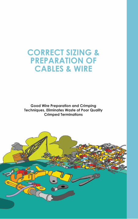
CORRECT SIZING & PREPARATION OF CABLES & WIRE
Good Wire Preparation and Crimping Techniques, Eliminates Waste of Poor Quality
Crimped Terminations
5
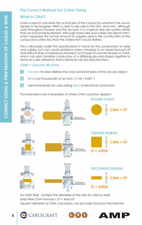
The Correct Method For Cable Sizing
Circular mil area defines the cross-sectional area of the circular object. C
Used extensively for calculating Area of electrical conductors.
M Mil is one thousandth of an inch. (1 mil = 0.001”)
A
For Solid Wire - Multiply the diameter of the wire (in mils) by itself. Solid Wire CMA Formula = D2 = Area D2
Square millimetre to CMA calculators can be easily found on the internet.
CMA = Circular Mil Area
CABLECRAFT AMP
CO
RREC
T SI
ZIN
G &
PRE
PARA
TIO
N O
F C
ABL
ES &
WIR
E
CMA is used to calculate the actual size of the conductor whether it be round, square or rectangular. AWG is used to size wire in the USA, and mm2, although used throughout Europe and the far east, it is a typical wire size system rather than an actual measurement. Although many wire and cables are sized in mm2, when measured the actual amount of copper used in the construction of the conductor is often less than the stated mm2 would define.
This is allowable under the specifications in force for the construction of wires and cables, but can cause problems when crimping to an expected pull off and millivolt drop or resistance standard. So it is best to convert all sizes to CMA, which can also combine conductors of a differing size and shape together to arrive at a size reference that a terminal can be selected from.
What is CMA?
Pictured below are 3 examples of where CMA could be applied.
DIE
CMA = D2
ROUND CABLE
D
TERMINAL
INDENT
CMA = D2
SQUARE BUSBAR
D
DIE
TERMINAL
INDENT
CMA = D2
RECTANGLE BUSBAR
DTERMINAL
INDENT
DIE
D = AREA
D = AREA
6CABLECRAFT AMP
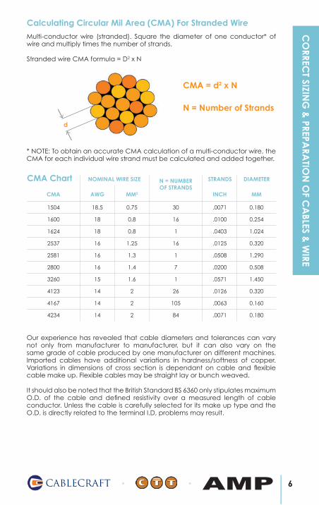
CMA AWG MM2
N = NUMBEROF STRANDS
INCH MM
1504 18.5 0.75 30 .0071 0.180
1600 18 0.8 16 .0100 0.254
1624 18 0.8 1 .0403 1.024
2537 16 1.25 16 .0125 0.320
2581 16 1.3 1 .0508 1.290
2800 16 1.4 7 .0200 0.508
3260 15 1.6 1 .0571 1.450
4123 14 2 26 .0126 0.320
4167 14 2 105 .0063 0.160
4234 14 2 84 .0071 0.180
Calculating Circular Mil Area (CMA) For Stranded Wire
Multi-conductor wire (stranded). Square the diameter of one conductor* of wire and multiply times the number of strands.
Stranded wire CMA formula = D2 x N
d
CMA = d2 x N
N = Number of Strands
* NOTE: To obtain an accurate CMA calculation of a multi-conductor wire, the CMA for each individual wire strand must be calculated and added together.
CMA Chart STRANDS DIAMETERNOMINAL WIRE SIZE
Our experience has revealed that cable diameters and tolerances can vary not only from manufacturer to manufacturer, but it can also vary on the same grade of cable produced by one manufacturer on different machines. Imported cables have additional variations in hardness/softness of copper. Variations in dimensions of cross section is dependant on cable and flexible cable make up. Flexible cables may be straight lay or bunch weaved.
It should also be noted that the British Standard BS 6360 only stipulates maximum O.D. of the cable and defined resistivity over a measured length of cable conductor. Unless the cable is carefully selected for its make up type and the O.D. is directly related to the terminal I.D, problems may result.
CO
RRECT SIZIN
G &
PREPARA
TION
OF C
ABLES &
WIRE
7 CABLECRAFT AMP
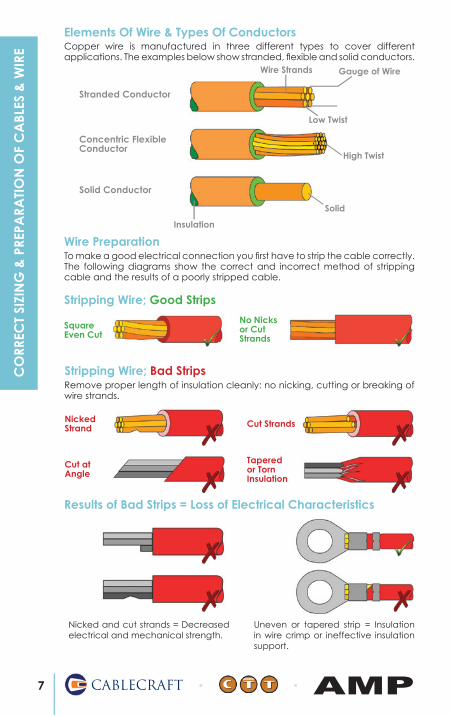
Elements Of Wire & Types Of Conductors
Wire Strands Gauge of Wire
Low Twist
High Twist
Solid
Insulation
Stranded Conductor
Concentric Flexible Conductor
Solid Conductor
Wire Preparation
Stripping Wire; Bad Strips
NickedStrand Cut Strands
Cut at Angle
Tapered or Torn Insulation
Remove proper length of insulation cleanly: no nicking, cutting or breaking of wire strands.
SquareEven Cut
No Nicks or Cut Strands
Stripping Wire; Good Strips
To make a good electrical connection you first have to strip the cable correctly. The following diagrams show the correct and incorrect method of stripping cable and the results of a poorly stripped cable.
Results of Bad Strips = Loss of Electrical Characteristics
Nicked and cut strands = Decreased electrical and mechanical strength.
Uneven or tapered strip = Insulation in wire crimp or ineffective insulation support.
Copper wire is manufactured in three different types to cover different applications. The examples below show stranded, flexible and solid conductors.
CO
RREC
T SI
ZIN
G &
PRE
PARA
TIO
N O
F C
ABL
ES &
WIR
E
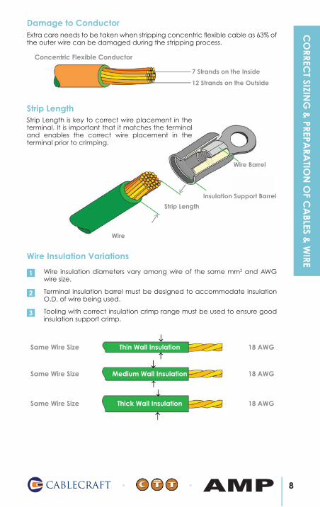
7 Strands on the Inside
12 Strands on the Outside
8CABLECRAFT AMP
Damage to ConductorExtra care needs to be taken when stripping concentric flexible cable as 63% of the outer wire can be damaged during the stripping process.
Concentric Flexible Conductor
18 AWG
18 AWG
18 AWG
Same Wire Size
Same Wire Size
Same Wire Size
Thin Wall Insulation
Medium Wall Insulation
Thick Wall Insulation
Wire Insulation Variations
Wire Barrel
Insulation Support Barrel
Wire
Strip Length
Strip LengthStrip Length is key to correct wire placement in the terminal. It is important that it matches the terminal and enables the correct wire placement in the terminal prior to crimping.
Wire insulation diameters vary among wire of the same mm2 and AWG wire size.
1
Terminal insulation barrel must be designed to accommodate insulation O.D. of wire being used.
2
Tooling with correct insulation crimp range must be used to ensure good insulation support crimp.
3
CO
RRECT SIZIN
G &
PREPARA
TION
OF C
ABLES &
WIRE
9 CABLECRAFT AMP
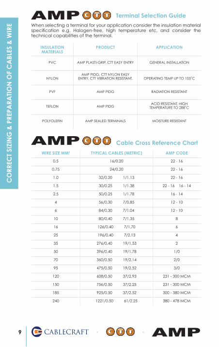
INSULATIONMATERIALS
PRODUCT APPLICATION
PVC AMP PLASTI-GRIP, CTT EASY ENTRY GENERAL INSTALLATION
NYLONAMP PIDG, CTT NYLON EASY
ENTRY, CTT VIBRATION RESISTANT. OPERATING TEMP UP TO 105˚C
PVF AMP PIDG RADIATION RESISTANT
TEFLON AMP PIDGACID RESISTANT, HIGH
TEMPERATURE TO 288˚C
POLYOLEFIN AMP SEALED TERMINALS MOISTURE RESISTANT
Terminal Selection Guide
Cable Cross Reference Chart
WIRE SIZE MM2 TYPICAL CABLES (METRIC) AMP CODE
0.5 16/0.20 22 - 16
0.75 24/0.20 22 - 16
1.0 32/0.20 1/1.13 22 - 16
1.5 30/0.25 1/1.38 22 - 16 16 - 14
2.5 50/0.25 1/1.78 16 - 14
4 56/0.30 7/0.85 12 - 10
6 84/0.30 7/1.04 12 - 10
10 80/0.40 7/1.35 8
16 126/0.40 7/1.70 6
25 196/0.40 7/2.13 4
35 276/0.40 19/1.53 2
50 396/0.40 19/1.78 1/0
70 360/0.50 19/2.14 2/0
95 475/0.50 19/2.52 3/0
120 608/0.50 37/2.93 231 - 300 MCM
150 756/0.50 37/2.25 231 - 300 MCM
185 925/0.50 37/2.52 300 - 380 MCM
240 1221/0.50 61/2.25 380 - 478 MCM
When selecting a terminal for your application consider the insulation material specification e.g. Halogen-free, high temperature etc, and consider the technical capabilities of the terminal.
AMP
AMP
CO
RREC
T SI
ZIN
G &
PRE
PARA
TIO
N O
F C
ABL
ES &
WIR
E

CRIMP TERMINAL TYPES
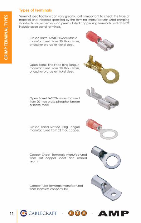
Open Barrel, End Feed Ring Tonguemanufactured from 20 thou brass, phosphor bronze or nickel steel.
Types of Terminals
Open Barrel FASTON manufactured from 20 thou brass, phosphor bronze or nickel steel.
Copper Sheet Terminals manufactured from flat copper sheet and brazed seams.
Copper Tube Terminals manufactured from seamless copper tube.
Terminal specifications can vary greatly, so it is important to check the type of material and thickness specified by the terminal manufacturer. Most crimping standards are written around pre-insulated copper ring terminals and do NOT include open barrel terminals.
Closed Barrel Slotted Ring Tongue manufactured from 32 thou copper.
Closed Barrel FASTON Receptaclemanufactured from 20 thou brass, phosphor bronze or nickel steel.
11 CABLECRAFT AMP
CRI
MP
TERM
INA
L TY
PES

Terminal Base Metals
MATERIALS USED FOR REASON
COPPER Common Terminations Conductivity
BRASS Pins, Sockets Hard Material
ALUMINIUM AI Conductor Light Weight
NICKEL NI Conductors High Temp
BRONZE Termi Point Clips High Pressure
Tin or Tin alloy coatings are cost effective and reliable alternatives to gold if used according to the following guidelines:
Tin Commandments
Tin coated contacts should be mechanically stable in the mated condition. 1
Tin coated contacts need at least 100 grams contact normal force. 2
Tin coated contacts need lubrication.3
Tin coating is not recommended for continuous service at high temperatures.4
The choice of plated, reflowed, hot air leveled, or hot tin dipped coatings does not strongly affect the electrical performance of tin or tin alloy coated contacts.
5
Electroplated tin coatings should be at least 100 microinches thick. 6
Mating tin coated contacts to gold coated contacts is not recommended.7
Sliding or wiping action contact engagement is recommended with tin coated contacts.
8
Tin coated contacts should not be used to make or break current.9
Tin coated contacts can be used under dry circuit or low level conditions. 10
12CABLECRAFT AMP
CRIM
P TERMIN
AL TY
PES
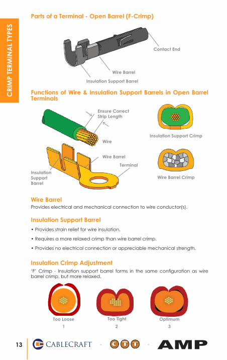
Functions of Wire & Insulation Support Barrels in Open Barrel Terminals
Wire BarrelProvides electrical and mechanical connection to wire conductor(s).
Insulation Support Barrel
• Provides strain relief for wire insulation.
• Requires a more relaxed crimp than wire barrel crimp.
• Provides no electrical connection or appreciable mechanical strength.
Wire Barrel Crimp
Insulation Support Crimp
Wire Barrel
Contact End
Insulation Support Barrel
Too Loose Too Tight Optimum
1 2 3
Insulation Crimp Adjustment‘F’ Crimp - Insulation support barrel forms in the same configuration as wire barrel crimp, but more relaxed.
Parts of a Terminal - Open Barrel (F-Crimp)
Wire Barrel
Insulation Support Barrel
Wire
Ensure Correct Strip Length
Terminal
13 CABLECRAFT AMP
CRI
MP
TERM
INA
L TY
PES

Crimp Inspection For Open Barrel Terminals
Cutoff tabs must be visible at insulation barrel and mating end of terminal.1
Wire strands must be visible at contact end of wire barrel but must not extend past area indicated.
2
Wire strands and insulation must both be visible anywhere between wire barrel and insulation barrel.
3
Bellmouth must be visible at wire end of wire barrel. 4
Wire strands must be visible between wire stop and end of wire barrel. 1
2 Bellmouth must be visible at window end of wire barrel.
3 Wire insulation must be inside insulation support sleeve.
Wire strands must be visible anywhere in this area.
Wire strands and insulation must both be visible anywhere in this area.
Barrel must be closed with no loose or trapped strands.
Bellmouth must be visible.
Cutoff tabs must be visible.
Advantages of Insulation Support Stress Point
Checking Crimp Height
Check crimp height of finished termination using crimp height comparator.
Crimp height data is found in instruction sheet (hand tools) or on data plate (applicators).
Wire Barrel
Anvil
1
2
14CABLECRAFT AMP
CRIM
P TERMIN
AL TY
PES
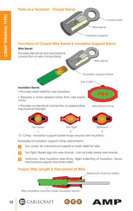
Wire Barrel:
Wire Barrel
Insulation Support
Contact End
Wire Barrel
Insulation Support Barrel
Proper Strip Length & Placement of Wire
Functions of Closed Wire Barrel & Insulation Support Barrel
Insulation Barrel:
Wire Barrel Crimp
Too Loose Too Tight Optimum
1 2 3
‘O’ Crimp - Insulation support barrel wraps around wire insulation.
Examples of insulation support crimp adjustments:
Too Loose: No mechanical support or strain relief for wire.1
Too Tight: Barrel digs into wire strands - can actually break wire strands.2
Optimum: Wire insulation held firmly. Slight indenting of insulation. Good mechanical support and strain relief.
3
Parts of a Terminal - Closed Barrel
Provides electrical and mechanical connection of wire conductor(s).
Bellmouth must be visible
Wire insulation must be inside insulation barrel.
• Provides strain relief for wire insulation.
• Requires a more relaxed crimp than wire barrel crimp.
• Provides no electrical connection or appreciable mechanical strength.
Dot Code
15 CABLECRAFT AMP
CRI
MP
TERM
INA
L TY
PES
E
C
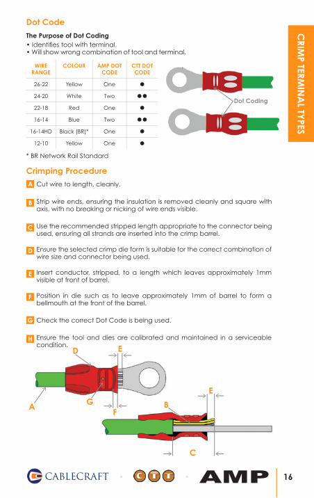
Dot Code
The Purpose of Dot Coding• Identifies tool with terminal.• Will show wrong combination of tool and terminal.
WIRE RANGE
COLOUR AMP DOT CODE
CTT DOT CODE
26-22 Yellow One
24-20 White Two
22-18 Red One
16-14 Blue Two
16-14HD Black (BR)* One
12-10 Yellow One
Dot Coding
* BR Network Rail Standard
Crimping Procedure
Cut wire to length, cleanly. A
Strip wire ends, ensuring the insulation is removed cleanly and square with axis, with no breaking or nicking of wire ends visible.
B
Use the recommended stripped length appropriate to the connector being used, ensuring all strands are inserted into the crimp barrel.
C
Ensure the selected crimp die form is suitable for the correct combination of wire size and connector being used.
D
Insert conductor, stripped, to a length which leaves approximately 1mm visible at front of barrel.
E
Position in die such as to leave approximately 1mm of barrel to form a bellmouth at the front of the barrel.
F
Check the correct Dot Code is being used.G
Ensure the tool and dies are calibrated and maintained in a serviceable condition.
H
A
D
G
E
FB
16CABLECRAFT AMP
CRIM
P TERMIN
AL TY
PES
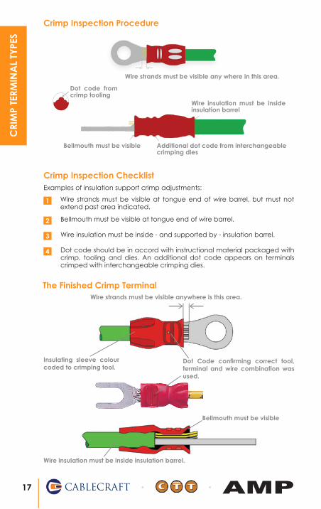
The Finished Crimp Terminal
Bellmouth must be visible
Wire insulation must be inside insulation barrel.
Dot Code confirming correct tool, terminal and wire combination was used.
Wire strands must be visible anywhere is this area.
Insulating sleeve colour coded to crimping tool.
Examples of insulation support crimp adjustments:
Wire strands must be visible at tongue end of wire barrel, but must not extend past area indicated.
1
Bellmouth must be visible at tongue end of wire barrel.2
Wire insulation must be inside - and supported by - insulation barrel.3
Dot code should be in accord with instructional material packaged with crimp, tooling and dies. An additional dot code appears on terminals crimped with interchangeable crimping dies.
4
Crimp Inspection Procedure
Wire strands must be visible any where in this area.
Bellmouth must be visible Additional dot code from interchangeable crimping dies
Wire insulation must be inside insulation barrel
Dot code from crimp tooling
Crimp Inspection Checklist
17 CABLECRAFT AMP
CRI
MP
TERM
INA
L TY
PES
Inc
rea
sing
Me
ch
an
ica
l Str
en
gth
Increasing Crimping ForceDecreasing Crimp Height
Mechanical Strength
Decreasing Crimp Height
Inc
rea
sing
Me
ch
an
ica
l St
ren
gth
& E
lec
tric
al P
erf
orm
an
ce
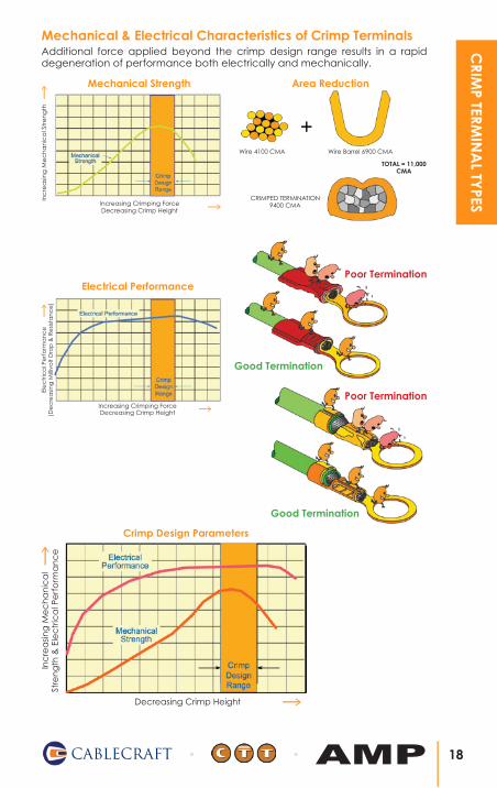
Additional force applied beyond the crimp design range results in a rapid degeneration of performance both electrically and mechanically.
Mechanical & Electrical Characteristics of Crimp TerminalsEl
ec
tric
al P
erf
orm
an
ce
(De
cre
asin
g M
illiv
olt
Dro
p &
Re
sista
nc
e)
Increasing Crimping ForceDecreasing Crimp Height
Electrical Performance
18CABLECRAFT AMP
CRIM
P TERMIN
AL TY
PES
Wire 4100 CMA Wire Barrel 6900 CMA
TOTAL = 11,000 CMA
CRIMPED TERMINATION 9400 CMA
Area Reduction
Poor Termination
Good Termination
Crimp Design Parameters
Good Termination
Poor Termination

Copper Tube Power Terminals The technique of crimping a terminal onto an electrical conductor has been used for over 60 years and is the dominant connecting technique for power cables.
The most important reasons for the success of this system are simplicity and safety. Cold compression is the optimum technique which provides both.
This system contains from the smallest conductor, 1.5mm2, to the largest 1000mm2 cross section, a tested combination of terminal size and tool geometry related to the actual size of the conductor.
Manufacturers choose to apply this combination in different ways, for example; a terminal with little material wall thickness in the barrel can be crimped with a press die designed for this situation. The same terminal crimped with another die from a different system, where the die is designed for a terminal with a thicker wall thickness (larger barrel), would result in massive under-crimping which in turn could cause overheating, due to poor electrical contact.
It is of the utmost importance to always check that the tools and terminals are tested together and are purchased from the same manufacturer.
Cablecraft-CTT can offer a fully matched system and advise on suitable terminals for all applications.
Different conductor materials are often crimped with completely different die geometry. For copper, the most common and effective method is the hexagonal crimp. This shape gives a smooth and mechanically strong crimp with little or no risk of the conductor strands being broken.
When crimping aluminium it is important to break the layers of insulating oxide as efficiently as possible, and the indent crimp is the most effective method.
The most important system component is the operator. This person must be provided with the necessary information and training to enable them to make a perfect crimp. A high quality product, tooling, clear instructions and comprehensive training course will help ensure this can be achieved every time.
Cablecraft CTT offers full in-house training to all crimping standards. For more information see page 35.
Hexagonal Crimp Double Pass ‘Collar’ Effect
Indent Type CrimpHexagonal Crimp Single Pass
19 CABLECRAFT AMP
CRI
MP
TERM
INA
L TY
PES

Copper Tube Power Terminals...Are They All The Same?
Terminals A and B are from different manufacturers which appear to be virtually identical in O.D. (outside diameter), I.D. (inside diameter) and wall thickness of the crimp barrel.
TERMINAL A TERMINAL B
They are stamp marked completely differently, terminal A marked for use with 240mm2 cable and the other marked for use with 185mm2 cable.
It is clearly critical that if crimping terminal B and using a die marked 185mm2
that it must be the one made by Manufacturer B as Manufacturer A’s 185mm2
die will be much smaller and would result in massive over crimping of terminal B, if the dies from Manufacturer A were used.
Similarly mixing the dies and tooling for Terminal A would result in massive under crimping. Never mix tooling and terminals from different manufacturers.
‘Spot the difference’ - the three terminals above are all marked as 240mm2
Barrel and palm lengths can also vary.
20CABLECRAFT AMP
CRIM
P TERMIN
AL TY
PES
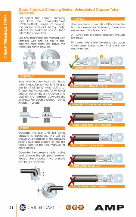
The completed crimp should look like the first two examples. Following these are examples of bad practice.
A - wire seen in correct position through site hole.
B - correct die reference embossed upon crimp area relates to terminal reference and wire size.
Insert wire into terminal - with hand tools it may be convenient to grip the terminal lightly while doing so. Check tool instructions for whether one or two crimps are required and position the terminal between die as show. For double crimps - crimp in order 1, 2, etc.
ASSEMBLY
Good Practice Crimping Guide: Uninsulated Copper Tube Terminals
Operate the tool until full crimp pressure is achieved. This will be shown by operation of the pressure relief valve and closure of the die faces. Refer to the tool manual for more details.
Operate the pressure relief valve and remove the crimped terminal. Repeat the process if two or more crimps are required.
CRIMP
LOOSE STRANDS NOT CRIMPED
CONDUCTOR DAMAGED
TWO CRIMPS OVERLAPPING
CONDUCTOR NOT FULLY INSERTED
CRIMPED TOO FAR FROM THE PALM
CRIMPED TOO NEAR THE PALM
CRIMPED CORRECTLY
A B
INSPECTFirst select the correct crimping tool from the comprehensive Cablecraft-CTT range of tooling. The range includes heavy duty, ratchet and hydraulic options. Then select the correct die:
Use only matched die marked with terminal wire size. Fit die to tool ensuring that both die have the same size crimp cavities.
21 CABLECRAFT AMP
CRI
MP
TERM
INA
L TY
PES

CABLECRAFT-CTT& AMP TOOLING
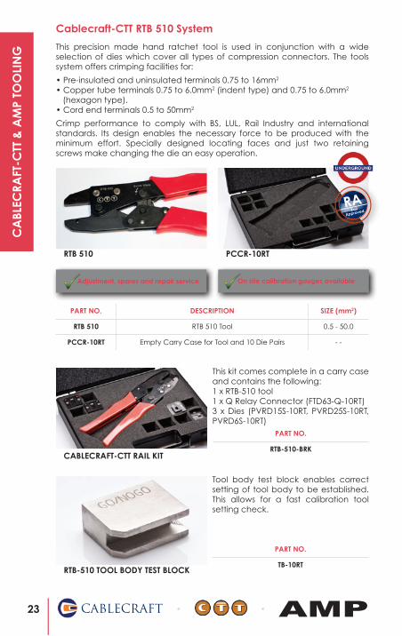
Cablecraft-CTT RTB 510 System
This precision made hand ratchet tool is used in conjunction with a wide selection of dies which cover all types of compression connectors. The tools system offers crimping facilities for:
• Pre-insulated and uninsulated terminals 0.75 to 16mm2
• Copper tube terminals 0.75 to 6.0mm2 (indent type) and 0.75 to 6.0mm2 (hexagon type). • Cord end terminals 0.5 to 50mm2
Crimp performance to comply with BS, LUL, Rail Industry and international standards. Its design enables the necessary force to be produced with the minimum effort. Specially designed locating faces and just two retaining screws make changing the die an easy operation.
RTB 510 PCCR-10RT
Adjustment, spares and repair service
PART NO. DESCRIPTION SIZE (mm2)
RTB 510 RTB 510 Tool 0.5 - 50.0
PCCR-10RT Empty Carry Case for Tool and 10 Die Pairs - -
Rail
ApprovedRA
On site calibration gauges available
CABLECRAFT-CTT RAIL KIT
This kit comes complete in a carry case and contains the following: 1 x RTB-510 tool1 x Q Relay Connector (FTD63-Q-10RT)3 x Dies (PVRD15S-10RT, PVRD25S-10RT, PVRD6S-10RT)
PART NO.
RTB-510-BRK
RTB-510 TOOL BODY TEST BLOCK
Tool body test block enables correct setting of tool body to be established. This allows for a fast calibration tool setting check.
PART NO.
TB-10RT
23 CABLECRAFT AMP
CA
BLEC
RAFT
-CTT
& A
MP
TOO
LIN
G
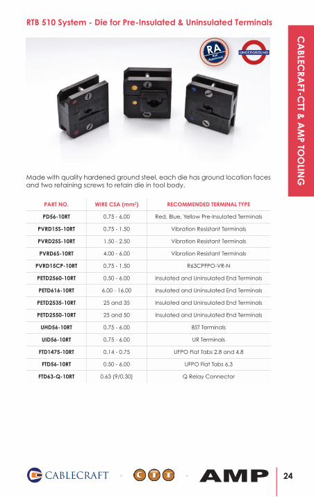
RTB 510 System - Die for Pre-Insulated & Uninsulated Terminals
PART NO. WIRE CSA (mm2) RECOMMENDED TERMINAL TYPE
PD56-10RT 0.75 - 6.00 Red, Blue, Yellow Pre-Insulated Terminals
PVRD15S-10RT 0.75 - 1.50 Vibration Resistant Terminals
PVRD25S-10RT 1.50 - 2.50 Vibration Resistant Terminals
PVRD6S-10RT 4.00 - 6.00 Vibration Resistant Terminals
PVRD15CP-10RT 0.75 - 1.50 R63CPFPO-VR-N
PETD2560-10RT 0.50 - 6.00 Insulated and Uninsulated End Terminals
PETD616-10RT 6.00 - 16.00 Insulated and Uninsulated End Terminals
PETD2535-10RT 25 and 35 Insulated and Uninsulated End Terminals
PETD2550-10RT 25 and 50 Insulated and Uninsulated End Terminals
UHD56-10RT 0.75 - 6.00 BST Terminals
UID56-10RT 0.75 - 6.00 UR Terminals
FTD1475-10RT 0.14 - 0.75 UFPO Flat Tabs 2.8 and 4.8
FTD56-10RT 0.50 - 6.00 UFPO Flat Tabs 6.3
FTD63-Q-10RT 0.63 (9/0.30) Q Relay Connector
Made with quality hardened ground steel, each die has ground location faces and two retaining screws to retain die in tool body.
Rail
ApprovedRA
24CABLECRAFT AMP
CA
BLECRA
FT-CTT &
AM
P TOO
LING
DIE PART NO. GAUGE PART NO.
PD56-10RT GPD5615-10RT
PD56-10RT GPD5625-10RT
PD56-10RT GPD566-10RT
PVRD15S-10RT GPVRD15-10RT
PVRD25S-10RT GPVRD25-10RT
PVRD65-10RT GPVRD6-10RT
PVRD15CP-10RT GPVRD15CP-10RT
GUHD5615-10RT
GUHD5625-10RT
GUHD564-10RT
GUHD566-10RT
GUID5615-10RT
GUID5625-10RT
GUID566-10RT
UID56-10RTAll 3 Required
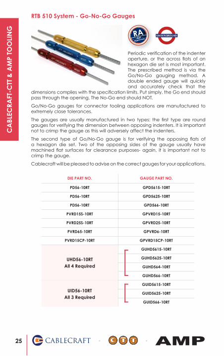
Periodic verification of the indenter aperture, or the across flats of an hexagon die set is most important. The prescribed method is via the Go/No-Go gauging method. A double ended gauge will quickly and accurately check that the
dimensions complies with the specification limits. Put simply, the Go end should pass through the opening. The No-Go end should NOT.
Go/No-Go gauges for connector tooling applications are manufactured to extremely close tolerances.
The gauges are usually manufactured in two types: the first type are round gauges for verifying the dimension between opposing indenters. It is important not to crimp the gauge as this will adversely affect the indenters.
The second type of Go/No-Go gauge is for verifying the opposing flats of a hexagon die set. Two of the opposing sides of the gauge usually have machined flat surfaces for clearance purposes- again, it is important not to crimp the gauge.
Cablecraft will be pleased to advise on the correct gauges for your applications.
RTB 510 System - Go-No-Go Gauges
Rail
ApprovedRA
UHD56-10RTAll 4 Required
25 CABLECRAFT AMP
CA
BLEC
RAFT
-CTT
& A
MP
TOO
LIN
G
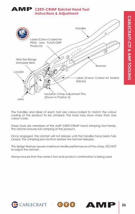
CERTI-CRIMP Ratchet Hand ToolInstructions & Adjustment
Ratchet
Label (Colour Coded for Sealed Splices)
Insulation Crimp Adjustment Pins(Shown in Position 3)
Jaws
Locator
Wire Size RangeStamped Here
Label (Colour Coded for PIDG and PLASTI-GRIP Products)
Handles
The handles and label of each tool are colour-coded to match the colour coding of the product to be crimped. The tools may show more than one colour code.
These tools are members of the AMP CERTI-CRIMP hand crimping tool family. The ratchet ensures full crimping of the product.
Always ensure that the correct tool and product combination is being used.
Once engaged, the ratchet will not release until the handles have been fully closed. The crimping jaws bottom before the ratchet releases.
This design feature assures maximum tensile performance of the crimp. DO NOT re-adjust the ratchet.
Rail
ApprovedRA
AMP
26CABLECRAFT AMP
CA
BLECRA
FT-CTT &
AM
P TOO
LING
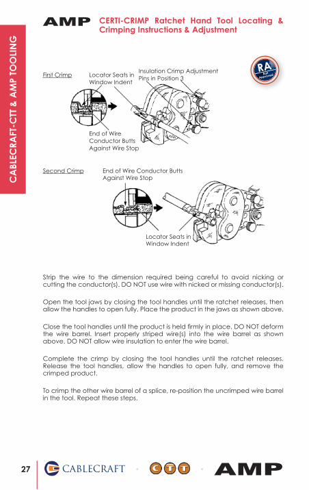
CERTI-CRIMP Ratchet Hand Tool Locating & Crimping Instructions & Adjustment
Insulation Crimp AdjustmentPins in Position 3Locator Seats in
Window Indent
End of Wire Conductor ButtsAgainst Wire Stop
End of Wire Conductor ButtsAgainst Wire Stop
Locator Seats inWindow Indent
Second Crimp
Strip the wire to the dimension required being careful to avoid nicking or cutting the conductor(s). DO NOT use wire with nicked or missing conductor(s).
Open the tool jaws by closing the tool handles until the ratchet releases, then allow the handles to open fully. Place the product in the jaws as shown above.
Close the tool handles until the product is held firmly in place. DO NOT deform the wire barrel. Insert properly striped wire(s) into the wire barrel as shown above. DO NOT allow wire insulation to enter the wire barrel.
Complete the crimp by closing the tool handles until the ratchet releases. Release the tool handles, allow the handles to open fully, and remove the crimped product.
To crimp the other wire barrel of a splice, re-position the uncrimped wire barrel in the tool. Repeat these steps.
First Crimp Rail
ApprovedRA
AMP
27 CABLECRAFT AMP
CA
BLEC
RAFT
-CTT
& A
MP
TOO
LIN
G

Double Action Hand Tool Instructions & Adjustment
Anvil Jaws Crimper Jaws
Back of Tool(Wire Side)
Crimping SectionSymbol
Insulation Crimp Adjustment (Pin in No. 3 Position)
CERTI-CRIMPRatchet
Tool Number
18 - 14
Wire RangeType of Crimp
#####
This double action hand crimping tool is designed to crimp ‘F Type’ positive lock terminals. It features two crimping jaws, each consisting of an anvil and a crimper. When closed, the jaws form two crimping chambers, each marked on the back side of the tool with the letters A and B.
The CERTI-CRIMP ratchet ensures full crimping of the terminal. Once engaged, the ratchet will not release until the tool handles have been fully closed.
Rail
ApprovedRA
AMP
28CABLECRAFT AMP
CA
BLECRA
FT-CTT &
AM
P TOO
LING

Double Action Hand Tool - Crimping Procedure
Insulation Barrel
Wire Barrel
Locator Slot
Strip Length: Wire BarrelLength Plus 0.79mm
mm2 AWGCRIMPLETTER
INSULATIONDIAMETER RANGE
0.7 - 2.0 18 - 14 A 2.4 - 3.2
2.1 - 4.0 14 - 11 B 3.6 - 4.3
WIRE SIZE
Select the appropriate terminal and wire size, making sure they are compatible. The wire size and insulation diameter must be within the specified range for the terminal. Strip the wire to the length shown below. Do not nick or cut the wire strands.
Then, proceed as follows:
1. Hold tool so that the back side is facing you.
2. Make certain that the ratchet is released by squeezing the tool handles and allowing them to open fully.
3. Looking straight into the back of appropriate crimp section, insert terminal (insulation barrel first) into the front of the crimp section. Position terminal in crimpers so the centre of the terminal wire barrel is in-line with the centre of the wire barrel crimping jaw.
4. Hold terminal in this position and squeeze tool handles together until jaws close just enough to retain terminal. Do not deform wire barrel or insulation barrel.
5. Insert a properly stripped wire through wire slot in locator and into wire barrel.
6. Hold the wire in place and squeeze the tool handles until the ratchet releases.
CAUTION: Squeezing the handles together too much will deform the wire barrel.
7. Allow the tool handles to open fully and remove the crimped terminal.
AMP
29 CABLECRAFT AMP
CA
BLEC
RAFT
-CTT
& A
MP
TOO
LIN
G
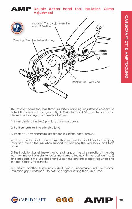
Double Action Hand Tool Insulation Crimp Adjustment
Insulation Crimp Adjustment Pin in No. 3 Position.
Crimping Chamber Letter Markings
Back of Tool (Wire Side)
This ratchet hand tool has three insulation crimping adjustment positions to adjust the wire insulation grip: 1-Tight, 2-Medium and 3-Loose. To obtain the desired insulation grip, proceed as follows:
1. Insert pins into the No.3 position, as shown above.
2. Position terminal into crimping jaws.
3. Insert an un-stripped wire just into the insulation barrel sleeve.
4. Crimp the terminal. Then remove the crimped terminal from the crimping jaws and check the insulation support by bending the wire back and forth once.
5. The insulation barrel sleeve should retain grip on the wire insulation. If the wire pulls out, move the insulation adjustment pins to the next tighter position (No. 2) and proceed. If the wire does not pull out, the pins are properly adjusted and the tool is ready for crimping.
6. Perform another test crimp. Adjust pins as necessary, until the desired insulation grip is obtained. Do not use a tighter setting than is required.
Rail
ApprovedRA
AMP
30CABLECRAFT AMP
CA
BLECRA
FT-CTT &
AM
P TOO
LING

Instructions For Setting The Insulation Crimp TightnessTo check and set the insulation support first set the pins on the insulation support crimp dies to the loosest setting (position 3) and insert and crimp an un-stripped wire. Hold the terminal in one hand and the wire in the other. Bend the wire up 90˚ and then down 90˚. The wire should remain held in the insulation support and not show any signs of pinching of the insulation. If the wire comes out during this test then the next tightest setting should be selected and the test repeated until a suitable setting is found. It may be that a terminal with a smaller insulation range may need to be selected. The wire should not be pulled laterally.
Heavy Head ToolInstructions & Adjustment
This heavy head tool is used to crimp terminals and splices onto larger wires.
Upper dies are fixed - lower dies move up and down.
Crimp Tools for Pre-Insulated Products. Illustration of:
A. Locator B. CTT Certi-Crimp™ ratchet C. Colour Coded Handle D. Insulation Crimp Adjustment
Insulated Terminals
Wire SideLocator
CTT Certi-Crimp™ Ratchet
Colour Coded Handles
Part Number
Rail
ApprovedRA
Heavy Head Tool - Locating Procedure
1. With tool handles in the open position:
A. For terminal - place in tool so tongue goes over locator. B. For splice - centre the window indent over locator.
2. Close handles until terminal or splice is held in place without deforming wire barrel.
3. Insert stripped wire until it bottoms and close handles until CTT Certi-Crimp™ ratchet releases.
4. To crimp other half of splice, remove splice from tool, rotate splice 180˚, reposition splice in tool and complete crimp 23 instructed in steps 2 and 3.
Caution: Make certain that the insulation crimping adjustment is correct before making production crimps.
Rail
ApprovedRA
AMP
AMP
31 CABLECRAFT AMP
CA
BLEC
RAFT
-CTT
& A
MP
TOO
LIN
G

CABLECRAFT-CTT TOOL CALIBRATION
& REPAIR CENTRE

CA
BLEC
RAFT
-CTT
TO
OL
CA
LIBR
ATI
ON
& R
EPA
IR C
ENTR
E All Cablecraft-CTT tools are made to the very highest specifications. To ensure their performance throughout their life they should be properly maintained, including daily spot checks for wear.
Tool Maintenance & Repair Centre
Cablecraft-CTT Tool CalibrationCablecraft-CTT offers a fast turnaround tool calibration service. It is important to have your tools calibrated on a yearly basis or every 10,000 crimps, which ever is sooner, to ensure you are getting the best crimp possible. After we have performed a number of tests on the tool to make sure it is up to the standards, we will provide you with a calibration certificate that will be matched to your tools asset number.
If any faults are found, the tool should be returned to the Cablecraft-CTT service department for immediate attention.
Pull Testing - Tensile Strength Tester
Daily Tool Checks• Remove dust, moisture and other contaminants from the tool with a clean brush or a soft, lint-free cloth. Do NOT use objects that could damage the tool.
• Lubricate with general purpose machine oil.
• Check for excessive wear on pins.
• Carefully inspect all parts including die for any wear, damage or breakage.
• Check that the ratchet mechanism is releasing only on completion of the crimp cycle and is, consequently, not too tight for normal use.
• Carry out tensile tests with the most frequently used terminal types including the largest and smallest sizes.
• If any faults are found, the tool should be returned to the Cablecraft-CTT service department for attention.
Cablecraft-CTT can offer a complete crimp pull test service. For details of current standards, please see page 48 or contact [email protected].
33 CABLECRAFT AMP

CABLECRAFT-CTT TRAINING COURSE

CA
BLEC
RAFT
-CTT
TRA
ININ
G C
OU
RSE
CERTIFICATE NO. 00140
Training of The above menTioned disciplines made by:
daTe:
daTe:signed:
has compleTed a Training course in
WIRE PREPARATION, CRIMPING, INSPECTION AND TEST,
WHICH ENABLES THEM TO CARRY OUT WORK WHICH MEETS AND EXCEEDS THE
REQUIREMENTS OF BS 5G178, 5057, 4579, BRITISH RAIL WOSS 560-4, LUL STANDARDS RSE024 & E6487A2.
This course covered The following disciplines:
CRIMPING SYSTEMS
APPRECIATION OF CRIMPING EQUIPMENT
OPERATION & MAINTENANCE OF CRIMPING TOOLS
PRACTICAL APPLICATION OF CRIMPING TOOLS
GAUGING & CALIBRATION
EvALUATION OF CRIMP JOINT STANDARDS
HEALTH & SAFETY
CABLECRAFTcreative wiring solutions
cablecraft house, circle business centre, blackburn road, houghton-regis, bedfordshire lu5 5ddTel: 01582 606 033 • fax: 01582 606 063 • email: [email protected] • web: www.cablecraft.co.uk
CABLECRAFTcreative wiring solutions
cablecrafT company
AMPTyco connecTiviTy
company
Certificate of Completion
ofname
company name
robbie cross01.01.11
chris JenarT - direcTor
01.01.11
A full product and crimp training programme is now available at Cablecraft-CTT. Below is an outline of what is covered in the course. If you are interested in more information about our training programme, please contact us or email: [email protected], where we will be happy to assist in your requirements.
Cablecraft-CTT CERT-N-CRIMP Training Course
The training course includes information on Wire Preparation, Crimping, Inspection and Test, which enables work to be carried out which meets and exceeds the requirements of BS 5G178, 5057, 4579, British Rail WOSS 560-4, LUL Standards RSE024 & E6487A2.
• Crimping Systems• Appreciation of Crimping Equipment• Operation & Maintenance of Crimping Tools• Practical Application of Crimping Tools• Gauging & Calibration• Evaluation of Crimp Joint Standards• Health & Safety
What’s Covered In The CERT-N-CRIMP Course
Certificate of Completion of CERT-N-CRIMP Training Course
35 CABLECRAFT AMP

IMAGE © TRANSPORT FOR LONDON 2005
RAIL INDUSTRYDOCUMENTATION
Components of a Quality Termination
Cablecraft-CTT Rail Log Sheet Data:Crimp Range & Insulation Diameter
286561
PAD LTR CRIMP HEIGHT WIRE SIZE
A 0.73 ± .002 (1.85 ± 0.05mm) 14
B .058 ± .002 (1.47 ± 0.05mm) 16
C NOT USED
D NOT USED
CRIMP SIZE TYPE RANGE
WIRE .110 (2.79mm) F 16 - 14
INSUL .150 (3.81mm) F .145 MAX.
CRIMPING DATA
WIRE STRIP LENGTH
.203 - .234
TERM APPL SPECNONE
FEED
.602
APPL INSTRUCTION
408 - 8040
SET UP GAGE
458637-1
LAYOUT
L1889
129
128
2 2 2 - C 1-354779-8 PIN, WIRE DISC (.3080) B 127
TERMINAL NAME, RECEPTACLE
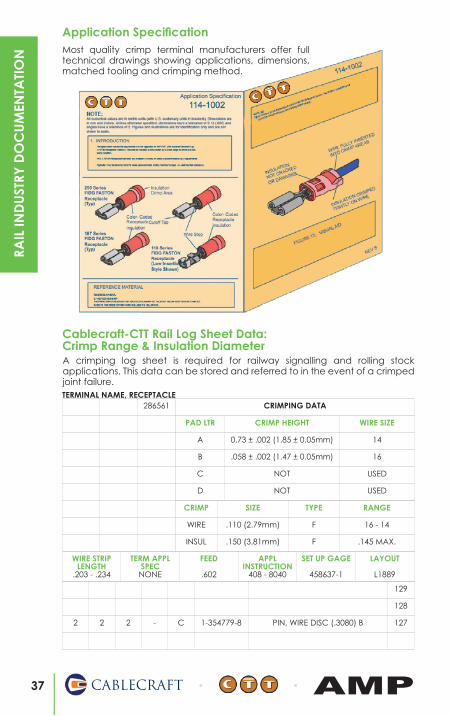
Application Specification
A crimping log sheet is required for railway signalling and rolling stock applications. This data can be stored and referred to in the event of a crimped joint failure.
Most quality crimp terminal manufacturers offer full technical drawings showing applications, dimensions, matched tooling and crimping method.
37 CABLECRAFT AMP
RAIL
IND
UST
RY D
OC
UM
ENTA
TIO
N
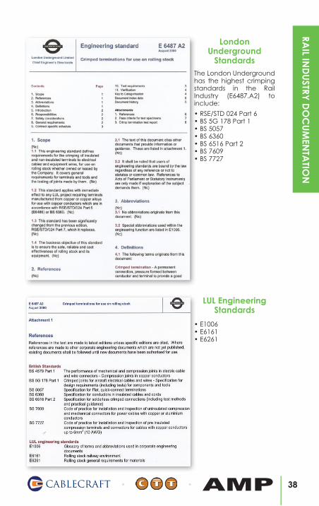
LondonUnderground
StandardsThe London Underground has the highest crimping standards in the Rail Industry (E6487.A2) to include:
• RSE/STD 024 Part 6• BS 5G 178 Part 1• BS 5057• BS 6360• BS 6516 Part 2• BS 7609• BS 7727
• E1006• E6161• E6261
LUL Engineering Standards
38CABLECRAFT AMP
RAIL IN
DU
STRY D
OC
UM
ENTA
TION
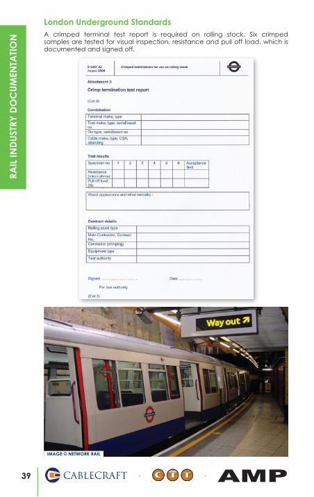
London Underground StandardsA crimped terminal test report is required on rolling stock. Six crimped samples are tested for visual inspection, resistance and pull off load, which is documented and signed off.
IMAGE © NETWORK RAIL
39 CABLECRAFT AMP
RAIL
IND
UST
RY D
OC
UM
ENTA
TIO
N

CABLECRAFT-CTT & AMPRAIL CABLE
REFERENCE CHARTS
DIE
SIZ
ING
REF
EREN
CE
STA
MPE
D O
N
TERM
INA
L A
FTER
CO
RREC
T C
RIM
PIN
G:
AM
POW
ER, S
OLI
STRA
ND
& C
TT
Term
ina
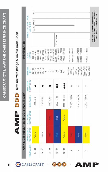
l Wire
Ra
nge
& C
olo
ur C
od
e C
hart
TERM
INA
L SI
ZEA
MP
PRO
DU
CT
CO
LOU
R C
OD
EC
TT P
ROD
UC
TC
OLO
UR
CO
DE
CM
A R
AN
GE
EMBO
SSED
CRI
MP
CO
DE
TERM
INA
L SI
ZEC
MA
RA
NG
EEM
BOSS
ED C
RIM
P C
OD
EA
MP
& C
TT
26 -
22
Yello
w20
2 -
810
24 -
20
Wh
ite32
0 -
1290
20 -
16
Re
dR
ed
509
- 32
60
16 -
14
Blu
eBl
ue
2050
- 5
180
12 -
10
Yello
wYe
llow
5180
- 1
3,10
0
8R
ed
13,1
00 -
20,
800
8
6Bl
ue
20,8
00 -
33,
100
6
4Ye
llow
33,1
00 -
52,
600
4
202
- 81
050
9 -
3260
2050
- 5
180
3260
- 8
230
5180
- 1
3100
1310
0 -
2080
020
800
- 33
100
3310
0 -
5260
052
600
- 83
700
8370
0 -
1195
0011
9500
- 1
5050
015
0500
- 1
9000
0
1900
00 -
231
000
2310
00 -
300
000
3000
00 -
380
000
3800
00 -
478
000
8500
00 -
950
000
9500
00 -
112
500
AM
P &
CTT
INSU
LATE
D (
PID
G &
PLA
STI-
GRI
P)U
NIN
SULA
TED
26 -
22
22 -
16
16 -
14
14 -
12
12 -
10
8 6 4 2 1/0
2/0
3/0
4/0
250
- 30
0M
CM
300
- 35
0M
CM
400
MC
M90
0 M
CM
1000
MC
M12
50 M
CM
1500
MC
M
AM
POW
ER
SOLI
STR
AN
DC
TT
Term
ina
l Wire
Ra
nge
& C
olo
ur C
od
e C
hart
AM
P
41 CABLECRAFT AMP
CA
BLEC
RAFT
-CTT
& A
MP
RAIL
CA
BLE
REFE
REN
CE
CH
ART
S
CA
BLECRA
FT-CTT &
AM
P RAIL C
ABLE REFEREN
CE C
HA
RTS
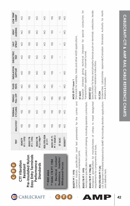
(A) R
ME
646A
(B) B
S4G
178
PT1
198
4(C
) El
ec
tric
al
Co
nta
ct
Resi
sta
nce
, In
sert
ion/
With
dra
wa
l Fo
rce
s
BS45
79 P
T 1
1970
Ge
ne
ral
ind
ust
ry
spe
cifi
ca
tion
(a
nd
te
st
pa
ram
ete
rs)
for
the
c
on
tro
l a
nd
p
erf
orm
an
ce
of c
om
pre
ssio
n jo
ints
.
BS5G
178
PT 1
199
3A
ero
spa
ce
sp
ec
ific
atio
n fo
r co
ntr
ol o
f crim
pin
g, i
nc
lud
ing
op
era
tor c
on
tro
l te
sts.
BS4G
178
PT 2
198
6 (B
)A
ero
spa
ce
sp
ec
ific
atio
n
for
ma
nu
fac
ture
rs
of
crim
ps
to
me
et
de
sign
/te
st
req
uire
me
nts
for c
om
po
ne
nts
an
d t
oo
ls.
RSE/
STD
/024
PT
7 (A
)LU
L Eq
uip
me
nt
sta
nd
ard
(re
pla
ce
d b
y E6
487
Al)
inc
lud
ing
vib
ratio
n a
pp
lica
tion
s a
nd
de
fine
d t
est
s.
TEST
MIL
LIV
OLT
THER
MA
LC
YC
LIN
GTE
NSI
LEPU
LL O
FFFL
UID
TEST
SIN
SULA
TIO
N
SUPP
ORT
DIE
LEC
TRIC
TE
STSA
LTSP
RAY
HEA
TA
GEI
NG
LOW
TEM
PC
RIM
P
BS45
79PT
1 1
970
YES
YES
NO
NO
NO
NO
NO
NO
NO
BS5G
178
PT 1
199
3YE
SYE
SYE
SYE
SYE
SYE
SYE
SYE
SYE
S
BS4G
178
PT 2
198
6(B)
YES
NO
NO
NO
NO
NO
NO
NO
NO
RSE/
STD
/024
PT 7
(A)
YES
YES
NO
NO
NO
NO
NO
NO
NO
MO
D 5
9.71
PT 1
ISSU
E 2
YES
YES
YES
YES
YES
YES
YES
YES
YES
ST 3
63C
YES
YES
YES
----
----
--YE
S
BS50
57(C
)N
ON
OYE
SN
ON
O--
NO
NO
NO
CTT
Vib
ratio
nRe
sist
ant
Pr
e-I
nsul
ate
d N
ylo
n Ea
sy E
ntry
Te
rmin
als
Perfo
rma
nce
St
and
ard
s
MO
D 5
9.71
Issu
e 1
Sta
nd
ard
s fo
r wa
rsh
ips,
ta
nks
an
d o
the
r MO
D a
pp
lica
tion
s.
ST 3
63C
Euro
pe
an
st
an
da
rd
giv
ing
te
ch
nic
al
sta
nd
ard
fo
r sp
ec
ial
co
nd
uc
tors
fo
r tr
an
spo
rta
tion
ap
plic
atio
ns
- c
ha
nn
el t
un
ne
l.
BS50
57 (
C)
Spe
cifi
ca
tion
for b
rass
an
d p
ho
sph
ur b
ron
ze p
ush
-on
te
rmin
als
- e
xtra
ctio
n, t
en
sile
a
nd
co
nta
ct
resis
tan
ce
inst
ruc
tion
s.
UL/
CSA
Un
de
rwrit
ers
La
bo
rato
ries
ap
pro
vals/
Ca
na
dia
n
Sta
nd
ard
s A
uth
orit
y fo
r N
ort
h
Am
eric
a &
Ca
na
da
.
42CABLECRAFT AMP
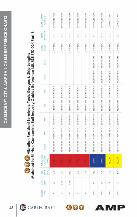
Vib
ratio
n Re
sist
ant
Te
rmin
als
, To
ols
Ga
uge
s &
Str
ip L
eng
ths
Ma
tche
d to
Fit
No
n-C
onc
ent
ric R
ail
Ind
ustr
y C
ab
les
Refe
renc
e L
UL
RSE
STD
024
Pa
rt 6
.
CA
BLE
TYPE
CSA
M
M2
INS
MA
XD
IA.
TERM
INA
LC
OLO
UR
AW
GM
3.5
M4
M5
M6
M8
M10
M12
HA
ND
TO
OL
STRI
P LE
NG
THW
IRE
CRI
MP
GA
UG
E
V0.
52.
4R
EDR
37PR
-VR
-NR
43PR
-VR
-NR
53PR
-VR
-NR
65PR
-VR
-NR
85PR
-RV
R-N
CTT
-RTB
510
5 -
6G
PVR
D15
S-10
RT
II0.
753.
1R
EDR
37PR
-VR
-NR
43PR
-VR
-NR
53PR
-VR
-NR
65PR
-VR
-NR
85PR
-RV
R-N
CTT
-RTB
510
5 -
6G
PVR
D15
S-10
RT
V0.
752.
62R
EDR
37PR
-VR
-NR
43PR
-VR
-NR
53PR
-VR
-NR
65PR
-VR
-NR
85PR
-RV
R-N
CTT
-RTB
510
5 -
6G
PVR
D15
S-10
RT
II1
3.5
RED
R37
PR-V
R-N
R43
PR-V
R-N
R53
PR-V
R-N
R65
PR-V
R-N
R85
PR-R
VR
-NC
TT-R
TB51
05
- 6
GPV
RD
15S-
10R
T
V1
2.8
RED
R37
PR-V
R-N
R43
PR-V
R-N
R53
PR-V
R-N
R65
PR-V
R-N
R85
PR-R
VR
-NC
TT-R
TB51
05
- 6
GPV
RD
15S-
10R
T
II+V
1.5
3.82
BLU
EB3
7PR
-VR
-NB4
3PR
-VR
-NB5
3PR
-VR
-NB6
3PR
-VR
-NB8
5PR
-RV
R-N
B10P
R-R
VR
-NB1
0PR
-RV
R-N
CTT
-RTB
510
5 -
6G
PVR
D25
S-10
RT
II+V
2.5
4.3
BLU
EB3
7PR
-VR
-NB4
3PR
-VR
-NB5
3PR
-VR
-NB6
3PR
-VR
-NB8
5PR
-RV
R-N
B10P
R-R
VR
-NB1
0PR
-RV
R-N
CTT
-RTB
510
5 -
6G
PVR
D25
S-10
RT
II+V
45.
12YE
LLO
WY3
7PR
-VR
-NY4
3PR
-VR
-NY5
3PR
-VR
-NY6
3PR
-VR
-NY8
5PR
-RV
R-N
Y10P
R-R
VR
-NY1
2PR
-RV
R-N
CTT
-RTB
510
6 -
7G
PVR
D6S
-10R
T
II+V
65.
7YE
LLO
WY3
7PR
-VR
-NY4
3PR
-VR
-NY5
3PR
-VR
-NY6
3PR
-VR
-NY8
5PR
-RV
R-N
Y10P
R-R
VR
-NY1
2PR
-RV
R-N
CTT
-RTB
510
6 -
7G
PVR
D6S
-10R
T
43 CABLECRAFT AMP
CA
BLEC
RAFT
-CTT
& A
MP
RAIL
CA
BLE
REFE
REN
CE
CH
ART
S
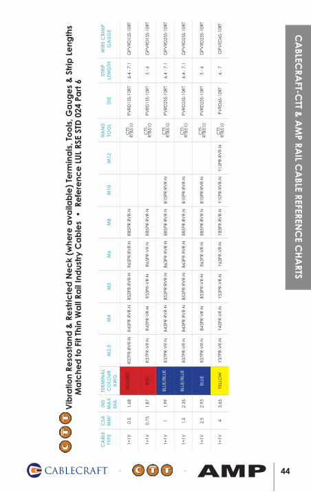
V
ibra
tion
Reso
sta
nd &
Re
stric
ted
Ne
ck
(whe
re a
vaila
ble
) Te
rmin
als
, To
ols
, Ga
uge
s &
Str
ip L
eng
ths
Ma
tche
d to
Fit
Thin
Wa
ll Ra
il In
dus
try
Ca
ble
s •
Re
fere
nce
LU
L RS
E ST
D 0
24 P
art
6
CA
BLE
TYPE
CSA
M
M2
INS
MA
XD
IA.
TERM
INA
LC
OLO
UR
AW
GM
3.5
M4
M5
M6
M8
M10
M12
HA
ND
TO
OL
DIE
STRI
P LE
NG
THW
IRE
CRI
MP
GA
UG
E
1+1V
0.5
1.68
RED
/RED
R37
PR-R
VR
-NR
43PR
-RV
R-N
R53
PR-R
VR
-NR
65PR
-RV
R-N
R85
PR-R
VR
-NC
TT-
RTB
510
PVR
D15
S-10
RT
6.4
- 7.
1G
PVR
D15
S-10
RT
1+1V
0.75
1.87
RED
R37
PR-V
R-N
R43
PR-V
R-N
R53
PR-V
R-N
R65
PR-V
R-N
R85
PR-R
VR
-NC
TT-
RTB
510
PVR
D15
S-10
RT
5 -
6G
PVR
D15
S-10
RT
1+1V
11.
99BL
UE/
BLU
EB3
7PR
-VR
-NB4
3PR
-RV
R-N
B53P
R-R
VR
-NB6
3PR
-RV
R-N
B85P
R-R
VR
-NB1
0PR
-RV
R-N
CTT
-R
TB51
0PV
RD
25S-
10R
T6.
4 -
7.1
GPV
RD
25S-
10R
T
1+1V
1.5
2.35
BLU
E/BL
UE
B37P
R-V
R-N
B43P
R-R
VR
-NB5
3PR
-RV
R-N
B63P
R-R
VR
-NB8
5PR
-RV
R-N
B10P
R-R
VR
-NC
TT-
RTB
510
PVR
D25
S-10
RT
6.4
- 7.
1G
PVR
D25
S-10
RT
1+1V
2.5
2.93
BLU
EB3
7PR
-VR
-NB4
3PR
-VR
-NB5
3PR
-VR
-NB6
3PR
-VR
-NB8
5PR
-RV
R-N
B10P
R-R
VR
-NC
TT-
RTB
510
PVR
D25
S-10
RT
5 -
6G
PVR
D25
S-10
RT
1+1V
43.
65YE
LLO
WY3
7PR
-VR
-NY4
3PR
-VR
-NY5
3PR
-VR
-NY6
3PR
-VR
-NY8
5PR
-RV
R-N
Y10P
R-R
VR
-NY1
2PR
-RV
R-N
CTT
-R
TB51
0PV
RD
6S-1
0RT
6 -
7G
PVR
D6S
-10R
T
44CABLECRAFT AMP
CA
BLECRA
FT-CTT &
AM
P RAIL C
ABLE REFEREN
CE C
HA
RTS
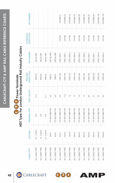
Pow
er T
erm
ina
lsH
DT
Typ
e F
or L
ond
on
Und
erg
roun
d R
ail
Ind
ustr
y C
ab
les
CA
BLE
TYPE
CSA
MM
2TE
RMIN
AL
TYPE
STRI
P LE
NG
THRA
TCH
ET
HA
ND
TO
OL
DIE
NU
MBE
RH
YD
RAU
LIC
HA
ND
TO
OL
DIE
NU
MBE
R
ALL
CA
BLE
TYPE
S0.
5 -
1.6m
m2
CTT
5 -
6R
TB-5
10U
ID 5
6-10
RT
ALL
CA
BLE
TYPE
S1.
0 -
2.6m
m2
CTT
RTB
-510
UID
56-
10R
T
ALL
CA
BLE
TYPE
S2.
7 -
6.6m
m2
CTT
6 -
7R
TB-5
10U
ID 5
6-10
RT
ALL
CA
BLE
TYPE
S4m
m2
CTT
HD
T TU
BE T
YPE
6.5
RTB
510
UH
D 5
6-10
RT
ALL
CA
BLE
TYPE
S6m
m2
CTT
HD
T TU
BE T
YPE
6.5
RTB
510
UH
D 5
6-10
RT
ALL
CA
BLE
TYPE
S6m
m2
CTT
HD
T TU
BE T
YPE
6.5
CR
T6-1
50C
RT6
-150
D-1
CH
T185
CH
T185
D-6
ALL
CA
BLE
TYPE
S10
mm
2C
TT H
DT
TUBE
TYP
E11
.5C
RT6
-150
CR
T6-1
50D
-1C
HT1
85C
HT1
85D
-10
ALL
CA
BLE
TYPE
S16
mm
2C
TT H
DT
TUBE
TYP
E13
CR
T6-1
50C
RT6
-150
D-2
CH
T185
CH
T185
D-1
6
ALL
CA
BLE
TYPE
S25
mm
2C
TT H
DT
TUBE
TYP
E13
CR
T6-1
50C
RT6
-150
D-2
CH
T185
CH
T185
D-2
5
ALL
CA
BLE
TYPE
S35
mm
2C
TT H
DT
TUBE
TYP
E15
CR
T6-1
50C
RT6
-150
D-2
CH
T185
CH
T185
D-3
5
ALL
CA
BLE
TYPE
S50
mm
2C
TT H
DT
TUBE
TYP
E17
CR
T6-1
50C
RT6
-150
D-2
CH
T185
CH
T185
D-5
0
ALL
CA
BLE
TYPE
S70
mm
2C
TT H
DT
TUBE
TYP
E20
CR
T6-1
50C
RT6
-150
D-1
CH
T185
CH
T185
0-70
ALL
CA
BLE
TYPE
S95
mm
2C
TT H
DT
TUBE
TYP
E27
CR
T6-1
50C
RT6
-150
D-1
CH
T185
CH
T185
D-9
5
ALL
CA
BLE
TYPE
S12
0mm
2C
TT H
DT
TUBE
TYP
E32
CR
T6-1
50C
RT6
-150
D-3
CH
T185
CH
T185
D-1
20
ALL
CA
BLE
TYPE
S15
0mm
2C
TT H
DT
TUBE
TYP
E32
CR
T6-1
50C
RT6
-150
D-3
CH
T185
CH
T185
D-1
50
45 CABLECRAFT AMP
CA
BLEC
RAFT
-CTT
& A
MP
RAIL
CA
BLE
REFE
REN
CE
CH
ART
S
TERM
INA
L BA
RREL
CO
LOU
RM
M2
RAN
GE
CM
AW
IRE
BARR
ELD
IAM
ETER
MIN
MA
XM
INM
AX
MIN
MA
X
YELL
OW
0.1
- 0.
420
2 -
810
2.08
PID
G
RED
/GR
EEN
0.2
- 0.
475
40.
840.
972.
79PI
DG
RES
TRIC
TED
EN
TRY
RED
/RED
0.4
- 0.
611
861.
041.
172.
79PI
DG
RES
TRIC
TED
EN
TRY
RED
/WH
ITE
0.6
- 0.
9519
001.
31.
422.
79PI
DG
RES
TRIC
TED
EN
TRY
RED
STA
ND
AR
D0.
35 -
1.5
509
- 32
601.
552.
033.
18PI
DG
RED
EX
PAN
DED
0.35
- 1
.550
9 -
3260
1.55
2.67
3.56
PID
G
OR
AN
GE
0.95
- 1
.427
501.
731.
42.
7PI
DG
BLU
E/BL
UE
0.95
- 1
.35
2426
1.47
1.6
3.3
PID
GR
ESTR
ICTE
D E
NTR
Y
BLU
E/G
REE
N1.
35 -
2.0
3831
1.85
1.98
3.3
PID
GR
ESTR
ICTE
D E
NTR
Y
BLU
E/ST
AN
DA
RD
1.0
- 2.
620
50 -
518
02.
162.
673.
81PI
DG
BLU
E EX
PAN
DED
1.0
- 2.
620
50 -
518
02.
162.
924.
32PI
DG
YELL
OW
/BLA
CK
1.0
- 2.
620
50 -
518
02.
673.
815.
854.
36.
355.
67.
62PI
DG
BLA
CK
1.0
- 2.
620
50 -
518
02.
164.
36.
35PI
DG
YELL
OW
/YEL
LOW
2.0
- 3.
060
882.
292.
415.
08PI
DG
RES
TRIC
TED
EN
TRY
YELL
OW
/BR
OW
N3.
0 -
5.0
1031
92.
93.
025.
08PI
DG
RES
TRIC
TED
EN
TRY
YELL
OW
STA
ND
AR
D2.
6 -
6.6
5180
- 1
3100
3.28
3.81
5.85
PID
G
YELL
OW
EX
PAN
DED
2.6
- 6.
651
80 -
131
003.
284.
36.
35PI
DG
YELL
OW
EX
P/EX
PAN
DED
2.6
- 66
5180
- 1
3100
3.28
5.6
7.62
PID
G
RED
6.64
- 1
0.5
1310
0 -
2080
07.
57A
MPL
IBO
ND
BLU
E10
.5 -
16.
820
800
- 33
100
9.58
AM
PLIB
ON
D
YELL
OW
16.8
- 2
6.7
3310
0 -
5260
011
.07
AM
PLIB
ON
D
RED
26.7
- 4
2.4
5260
0 -
8370
012
.82
AM
PLIB
ON
D
BLU
E42
.4 -
60.
683
700
- 11
9500
16.0
5A
MPL
IBO
ND
YELL
OW
60.6
- 7
6.3
1195
00 -
150
500
17.3
7A
MPL
IBO
ND
RED
76.3
- 9
6.3
1505
00 -
190
000
18.7
2A
MPL
IBO
ND
BLU
E96
.3 -
117
1900
00 -
231
000
20.2
3A
MPL
IBO
ND
STA
ND
ARD
EXPA
ND
EDIN
SULA
TIO
N S
UPP
ORT
RA
NG
EEX
P/EX
PAN
DED
46CABLECRAFT AMP
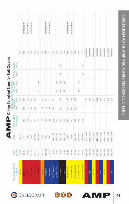
Crim
p T
erm
ina
l Siz
es
for R
ail
Ca
ble
sA
MP
CA
BLECRA
FT-CTT &
AM
P RAIL C
ABLE REFEREN
CE C
HA
RTS
CA
BLE
TYPE
AW
GIN
S M
AX
D
IA.
TERM
INA
LC
OLO
UR
AW
G
M3.
5M
4M
5M
6M
8H
AN
D T
OO
LST
RIP
LEN
GTH
PIN
SETT
ING
WIR
E C
RIM
PG
AU
GE
99M
O11
X(6
00V
)26
0.88
YELL
OW
3239
1532
3619
3240
7546
121
5 to
61
5749
18
99M
O11
X(6
00V
)24
0.98
YELL
OW
3239
1532
3619
3240
7546
121
5 to
61
5749
18
99M
O11
X(6
00V
)22
1.13
YELL
OW
3239
1532
3619
3240
7546
121
5 to
62
5749
18
99M
O11
X(6
00V
)20
1.4
RED
/RED
2
051
863-
31-
3205
51-3
2-36
153-
42-
3205
71-4
2-32
0572
-347
386/
5256
906.
4 to
7.1
157
4917
99M
O11
X(6
00V
)18
1.65
RED
/WH
ITE
20
2-31
649-
51-
3205
51-4
2-36
153-
52-
3205
71-5
2-32
0572
-447
386/
5256
906.
4 to
7.1
157
4917
99M
O11
X(6
00V
)16
1.9
BLU
E/BL
UE
16
2-32
0561
-31-
5186
4-0
5186
4-7
2-32
0563
-32-
3205
72-2
4738
7/52
5691
6.4
to 7
.11
5749
16
99M
O11
X(6
00V
)14
2.25
BLU
E/G
REE
N 1
451
864-
81-
5186
4-1
5186
4-9
2-32
0563
-42-
3205
75-3
4738
7/52
5691
6.4
to 7
.11
5749
16
99M
O11
X(6
00V
)12
2.6
YELL
OW
/YEL
LOW
12
2-36
161-
52-
3205
68-2
2-36
161-
32-
3205
69-5
2-32
0576
-259
239-
4/52
5692
9.5
to 1
0.3
157
4915
47 CABLECRAFT AMP
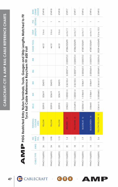
P
IDG
Re
stric
ted
Ent
ry N
ylo
n Te
rmin
als
, To
ols
, Ga
uge
s a
nd S
trip
Le
ngth
s M
atc
hed
to F
itTy
co
Ra
il C
ab
le R
efe
renc
e R
ayc
hem
99
600
Vo
ltA
MP
CA
BLEC
RAFT
-CTT
& A
MP
RAIL
CA
BLE
REFE
REN
CE
CH
ART
S
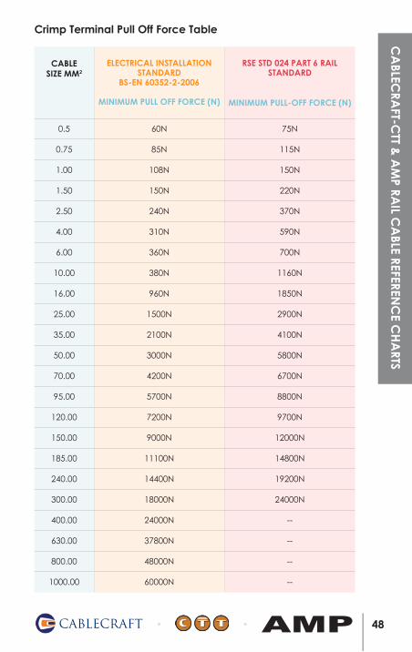
Crimp Terminal Pull Off Force Table
CABLE SIZE MM2
ELECTRICAL INSTALLATION STANDARD
BS-EN 60352-2-2006
MINIMUM PULL OFF FORCE (N)
RSE STD 024 PART 6 RAIL STANDARD
MINIMUM PULL-OFF FORCE (N)
0.5 60N 75N
0.75 85N 115N
1.00 108N 150N
1.50 150N 220N
2.50 240N 370N
4.00 310N 590N
6.00 360N 700N
10.00 380N 1160N
16.00 960N 1850N
25.00 1500N 2900N
35.00 2100N 4100N
50.00 3000N 5800N
70.00 4200N 6700N
95.00 5700N 8800N
120.00 7200N 9700N
150.00 9000N 12000N
185.00 11100N 14800N
240.00 14400N 19200N
300.00 18000N 24000N
400.00 24000N --
630.00 37800N --
800.00 48000N --
1000.00 60000N --
48CABLECRAFT AMP
CA
BLECRA
FT-CTT &
AM
P RAIL C
ABLE REFEREN
CE C
HA
RTS
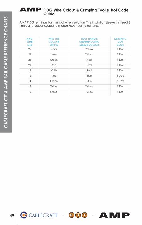
AWG WIRE SIZE
WIRE SIZE COLOUR STRIPES
TOOL HANDLE AND INSULATING SLEEVE COLOUR
CRIMPING DOT
CODE
26 Black Yellow 1 Dot
24 Blue Yellow 1 Dot
22 Green Red 1 Dot
20 Red Red 1 Dot
18 White Red 1 Dot
16 Blue Blue 2 Dots
14 Green Blue 2 Dots
12 Yellow Yellow 1 Dot
10 Brown Yellow 1 Dot
PIDG Wire Colour & Crimping Tool & Dot Code Guide
49 CABLECRAFT AMP
AMPC
ABL
ECRA
FT-C
TT &
AM
P RA
IL C
ABL
E RE
FERE
NC
E C
HA
RTS
AMP PIDG terminals for thin wall wire insulation. The insulation sleeve is striped 3 times and colour coded to match PIDG tooling handles.
50CABLECRAFT AMP
OPERATORS NAME
TOOL PART NO.
TOOL ASSET NO.
DATE PURCHASED
DATE CALIBRATED
Tool Calibration Record C
ABLEC
RAFT-C
TT & A
MP RA
IL CA
BLE REFERENC
E CH
ARTS

51 CABLECRAFT AMP
Notes

Notes
52CABLECRAFT AMP

53 CABLECRAFT AMP
Notes