cache architecture of modren multicore -...
TRANSCRIPT

Cache architecture of Modren multicore
Hao Luo

Outline
Overview
The Sun Fireplane System Interconnect
IBM POWER4 architecture
IBM BlueGene/Q overview

Overview

High Concurrency
Sun Fireplane : >64 processors
IBM POWER4 : up to 32-way SMP
IBM BGQ : 18 processor units + 4-way SMT
High throughput
Sun Fireplane : Peak system bandwidth 43 GBps
BGQ : 677.10 Tflops on Linpack as of November 2011

Sun Fireplane
“The Sun Fireplane System Interconnect”, Alan Charlesworth

Cache Coherency
Broadcast(snoopy) coherency
all address sent to all devices
low latency
Point-to-Point(directory) coherency
each address sent to the interested devices
high latency and complexity

Scalable Shared-Memory Protocol
Two-level Cache Coherency
Mid-size system (<24 processors): Snoopy
Large-size system (>24 processors): P2P

基情武侠】笑傲江湖

Separation of address and data networks
Enhance throughput and bandwidth
split-phase transactions
Addressing the challenge of limited capacity of resources

Broadcast Address Transaction
2-level bidirectional tree-structure address repeater
Outgoing request CPU0->AR2
Request transmit AR2->AR1
All devices see transaction AR0->CPU0
Root is order point and all CPU see transaction in same order at same time

Fireplane Cache State Transition

P2P coherency (MSI)
Global States
gM: global modified, valid, exclusive and dirty in this snooping coherence domain
gS: global shared, valid, clean potentially shared by other snooping coherence domain
gI: global invalid: invalid

Example of Fireplane Interconnect Operations

Within snooping coherence domain
Address request (ReadToShare)
Broadcast address
Snoop, each device examine coherency tags
Read from memory, data sent to dual CPU data switch
Transfer data, arrival

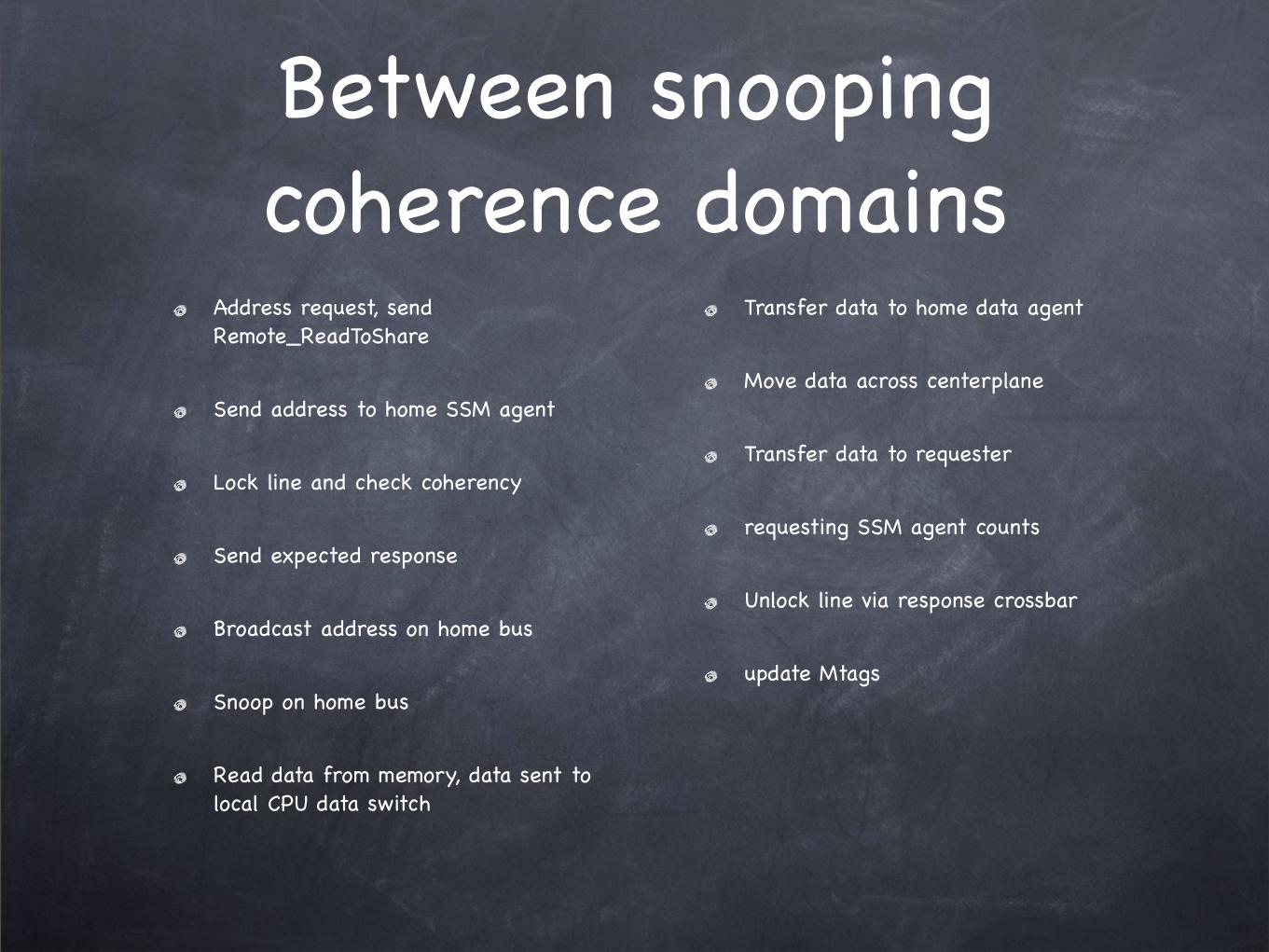
Between snooping coherence domains
Address request, send Remote_ReadToShare
Send address to home SSM agent
Lock line and check coherency
Send expected response
Broadcast address on home bus
Snoop on home bus
Read data from memory, data sent to local CPU data switch
Transfer data to home data agent
Move data across centerplane
Transfer data to requester
requesting SSM agent counts
Unlock line via response crossbar
update Mtags

When data is owned in cache
Cache-to-cache transfer
Inside snooping domain (cache send data directly)
In another snooping domain (three-way transfer to supply data)
home SSM -> owning SSM agent
owning SSM agent runs transaction on local bus, supply data directly

IBM POWER4 Architecture
“POWER4 System Microarchitecture”, J. M. Tendler, J. S. Dodson, J. S. Fields, Jr, H. Le, B. Sinharoy

Cache hierarchyL1 Cache
Low associativity
write-through, inclusive
L2 Cache
High associativity for high hit rate
L3 Cache
shared across chips, on-chip logic, off-chip memory

L1 Cache
L1 Data Cache: two 8-byte read and one 8-byte write per cycle
Two states: Valid/Invalid
L1 and L2 are inclusive
L2 and L3 have no inclusive guarantee

L2 Cache
Unified cache, shared by 2 cores
divided into 3 slices
4 coherency processors per slice
directory protocol
4 snoop processors per slice
snoop protocol

MESI protocol of L2 Cache
7 States
I, invalid: initial state
SL, shared, can be source to local requester in the module
S, shared: can not be sourced to other L2
M, modified: valid, exclusive, modified by this processor
Me, exclusive: valid, exclusive, not modified, reserved
Mu, unsolicited modified state: valid, exclusive, modified but not by this processor, reserved
T, tagged: valid data, modified wrt memory copy

L3 Cache
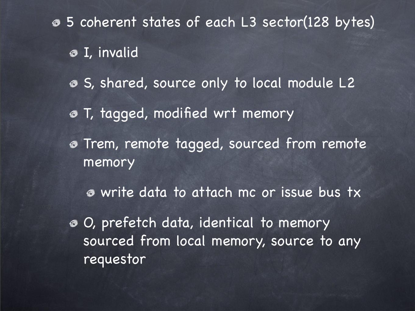
5 coherent states of each L3 sector(128 bytes)
I, invalid
S, shared, source only to local module L2
T, tagged, modified wrt memory
Trem, remote tagged, sourced from remote memory
write data to attach mc or issue bus tx
O, prefetch data, identical to memory sourced from local memory, source to any requestor

Multichip Module: 8-way SMP

L2 cache serves as “directory” to L1
directory style protocol within chip
Each chip writes to own bus, arbitrating among L2, IO controller and L3 controller.
Each chip snoops on all buses
snoop style protocol at chip level
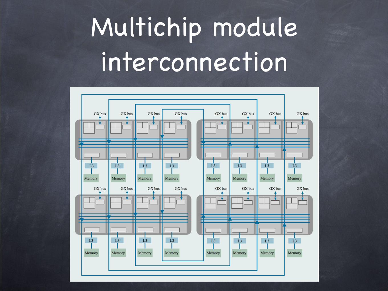
Multichip module interconnection

Ring topology
Each chip sends requests/commands and data on its own bus but snoop all buses
multichip module interconnect

Comparison

Sun Fireplane
Bidirectional tree
Snoop protocol at inner domain
Directory protocol at outer domain
Power 4
Set of rings
Directory protocol at inner domain
Snoop protocol at outer domain
IBM Blue Gene/Q
“The IBM Blue Gene/Q Compute Chip”, R. A. Haring et. al.
“IBM’s BlueGene/Q super chip grows 18th core”, http://www.theregister.co.uk/2011/08/22/ibm_bluegene_q_chip/

System-on-a-Chip design

64-bit instruction set, like Power series, different from previous BlueGene/L, BlueGene/P

In-order dispatch, execution and completion
16 Kb L1 DCache and 16 Kb L1 ICahce

Crossbar Switch
runs at half of clock frequency
peak bisection bandwidth 563GB/Sec
32MB embedded DRAM, as L2 cache
2 Memory controller, 1.33 GHz
each MC interface with 8 slices of L2 cache, bandwidth 42.7GB/Sec

17th Core
running Red Hat Enterprise Linux
offload operating system services, eliminate distracting OS noise
Interrupt handling
Async I/O
if core failure, remap core and bring 18th core online

359.5 square mm in area
1.47 billion transistors
cores all spin at 1.6 GHz
varying voltage at 0.8V
give up performance per core in trade of lower active and leakage power

Hierarchy

Compute card and optical interconnect have water block for cooling
60 - 65 degree Fahrenheit

Sequoia system obtained by Lawrence Livermore is 96 racks, 20 petaflops

Thanks