cad 360 helicopter supplement
TRANSCRIPT

香港特別行政區政府
民航處民航處民航處民航處
Civil Aviation Department
The Government of the
Hong Kong Special Administrative Region
CAD 360 – Helicopter Supplement
Guidance Document for
Helicopter AOC Holders
First Edition - January 2009


i July 2021 (Amdt 4)
RECORD OF AMENDMENTS
Amendment No Date of Issue Amended by (Signature)
First Edition January 2009 ***
Amendment 1 April 2015 ***
Amendment 2 December 2016 ***
Amendment 3 June 2018 ***
Amendment 4 July 2021 ***

Page No Date Page No Date Page No Date
ii July 2021 (Amdt 4)
CHECKLIST OF PAGES
i July 2021
ii July 2021
iii July 2021
iv July 2021
1/1 July 2021
1/2 July 2021
1/3 July 2021
1/4 July 2021
1/5 July 2021
1/6 July 2021
2/1 July 2021
2/2 July 2021
2/3 July 2021
2/4 July 2021
2/4 July 2021
2/6 July 2021
2/7 July 2021
2/8 July 2021
2/9 July 2021
2/10 July 2021
2/11 July 2021
2/12 July 2021
2/13 July 2021
2/14 July 2021
2/15 July 2021
2/16 July 2021
2/17 July 2021
2/18 July 2021
2/19 July 2021
2/20 July 2021
3/1 June 2018
3/2 June 2018
3/3 June 2018
3/4 June 2018
3/5 June 2018
3/6 June 2018
4/1 June 2018
4/2 June 2018
4/3 June 2018
4/4 June 2018
5/1 June 2018
5/2 June 2018
5/3 June 2018
5/4 July 2021
5/5 July 2021
5/6 July 2021
5/7 July 2021
5/8 July 2021
5/9 July 2021
5/10 July 2021
5/11 July 2021
5/12 July 2021
5/13 July 2021
5/14 July 2021
5/15 July 2021
5/16 July 2021
5/17 July 2021
5/18 July 2021
5/19 July 2021
5/20 July 2021
6/1 June 2018
6/2 June 2018
7/1 June 2018
7/2 June 2018
7/3 June 2018
7/4 June 2018
7/5 June 2018
7/6 June 2018
8/1 June 2018
8/2 June 2018
8/3 June 2018
8/4 June 2018
8/5 June 2018
8/6 June 2018
8/7 June 2018
8/8 June 2018
8/9 June 2018
8/10 June 2018
8/11 June 2018
8/12 June 2018
8/13 June 2018
8/14 June 2018

iii July 2021 (Amdt 4)
General Contents Chapter / Page
Foreword v
Chapter 1 – Definitions 1/1
Chapter 2 – Heliport Operating Minima 2/1
Chapter 3 – Fuel & Oil Requirements and Additional Fuel
Planning
3/1
& Management Procedures for Helicopters
Chapter 4 – Selection of Offshore Alternates – Helicopters 4/1
Chapter 5 – Performance – Helicopters 5/1
Chapter 6 – Helicopters – Public Transport Flight in VMC at
Night
6/1
Chapter 7 – Miscellaneous Provisions Affecting Helicopter
Operations
7/1
Chapter 8 – Additional Factors for Helicopter Pilot’s Training
and Periodic Test
8/1
iv July 2021 (Amdt 4)
Guidance Document for Helicopter AOC Holders
Foreword
Status
The Guidance Document for Helicopter AOC Holders is not law; failure to comply is
not an offence. The material it contains describes “best practice” means of compliance
with the Air Navigation (Hong Kong) Order 1995 (AN(HK)O) following the
provisions detailed in Annex 6 to the Convention on International Civil Aviation.
Operators will therefore have to provide cogent reasons, justified in safety terms, for
wishing to adopt an alternative means of compliance.
Aim
The aim of this document is not to duplicate information found in the CAD 360.
It is designed to provide information to helicopter AOC holders and amplification
of items that the operator may wish to include in the operations manual in addition
to the CAD 360 Air Operator’s Certificate Requirements. Some material may be used
verbatim; other information may need to be adapted to apply to the specific operation.
Finally, it offers useful information that may be of interest and relevance to the
operator.
Definitions
Where a term is used which is defined in a relevant International Civil Aviation
Organization (ICAO) Annex or Procedures for Air Navigation Services (PANS)
document, that definition will apply unless there is a different definition in the
AN(HK)O. Differences to ICAO definitions and Standard and Recommended
Practices are identified in the Aeronautical Information Publication (AIP).
Chapter 1/1 July 2021 (Amdt 4)
Chapter 1 - Definitions
When the following terms are used in the Hong Kong Civil Aviation Department
(HKCAD) for international operations with helicopters, they have the following
meanings:
Aerodrome. A defined area on land or water (including any buildings, installations
and equipment) intended to be used either wholly or in part for the arrival, departure
and surface movement of aircraft.
Alternate heliport. A heliport to which a helicopter may proceed when it becomes
either impossible or inadvisable to proceed to or to land at the heliport of intended
landing. Alternate heliports include the following:
Take-off alternate. An alternate heliport at which a helicopter can land should this
become necessary shortly after take-off and it is not possible to use the heliport of
departure
En-route alternate. A heliport at which a helicopter would be able to land after
experiencing an abnormal or emergency condition while en route.
Destination alternate. An alternate heliport to which a helicopter may proceed should
it become either impossible or inadvisable to land at the heliport of intended landing.
Note. The heliport from which a flight departs may be an en-route or a destination
alternate heliport for the flight.
Approach and landing operations using instrument approach procedures.
Categories of precision approach and landing operations:
Category I (Cat I) operation. A precision approach and landing with a decision height
not lower than 60 m (200 ft), and with either a visibility not less than 800 m or a
runway visual range not less than 550 m.
Category II (Cat II) operation. A precision instrument approach and landing with a
decision height lower than 60 m (200 ft), but not lower than 30 m (100 ft), and a
runway visual range not less than 300 m.
Category III (Cat III) operation. A precision approach and landing with a decision
height lower than 30 m (100 ft) or no decision height and a runway visual range less
than 300 m or no runway visual range limitations.
Approach and landing phase – helicopters. That part of the flight from 300 m (1000
ft) above the elevation of the FATO, if the flight is planned to exceed this height, or
from the commencement of the descent in the other cases, to a landing or to the
balked landing point.
Congested hostile environment. A hostile environment within a congested area.

Chapter 1/2 July 2021 (Amdt 4)
Crew member. A person assigned by an operator of an aircraft to be involved in the
operation of the aircraft during any portion of a flight.
Defined point after take-off (DPATO). The point, within the take-off and initial
climb phase, before which the helicopter’s ability to continue the flight safely, with
one engine inoperative, is not assured and a forced landing may be required.
Note. Defined points apply to helicopters operating in performance class 2 only.
Defined point before landing (DPBL). The point, within the approach and landing
phase, after which the helicopter’s ability to continue the flight safely, with one
engine inoperative, is not assured and a forced landing may be required.
Duty. Any task that flight or cabin crew members are required by the operator to
perform, including, for example, flight duty, administrative work, training,
positioning and standby when it is likely to induce fatigue.
Duty period. A period which starts when a flight or cabin crew member is required
by an operator to report for or to commence a duty and ends when that person is free
from all duties.
Elevated heliport. A heliport located on a raised structure on land which is at least
3m from the surrounding surface.
En-route phase. That part of the flight from the end of the take-off and initial climb
phase to the commencement of the approach and landing phase.
Fatigue. A physiological state of reduced mental or physical performance capability
resulting from sleep loss, extended wakefulness, circadian phase, and/or workload
(mental and/or physical activity) that can impair a person’s alertness and ability to
adequately perform safety-related operational duties.
Fatigue risk management system (FRMS). A data-driven means of continuously
monitoring and managing fatigue-related safety risks, based upon scientific principles
and knowledge as well as operational experience that aims to ensure relevant
personnel are performing at adequate levels of alertness.
Final approach and take-off area (FATO). A defined area over which the final phase
of the approach manoeuvre to hover or landing is completed and from which the take-
off manoeuvre is commenced. When the FATO is to be used by helicopters in
performance Class 1, the defined area includes the rejected take-off area available.
Flight duty period. A period which commences when a flight or cabin crew member
is required to report for duty that includes a flight or series of flights and which
finishes when the aircraft finally comes to rest and the engines are shut down at the
end of the last flight on which he/she is a crew member.
Flight Safety Documents System. A set of interrelated documentation established by
the operator, compiling and organizing information necessary for flight and ground

Chapter 1/3 July 2021 (Amdt 4)
operations, comprising as a minimum, the operations manual and the operator’s
control manual
Flight Simulation Device. Any one of the following three types of apparatus in which
flight conditions are simulated on the ground.
A flight simulator, which provides an accurate representation of the flight deck of a
particular aircraft type to the extent that the mechanical, electrical and electronic, etc.
aircraft systems control functions, the normal environment of flight crew members,
and the performance and flight characteristics of that type of aircraft are realistically
simulated.
A flight procedures trainer, which provides a realistic flight deck environment, and
which simulates instrument responses, simple control functions of mechanical,
electrical, electronics, etc. aircraft systems, and the performance and flight
characteristics of aircraft of a particular class.
A basic instrument flight trainer, which is equipped with appropriate instruments, and
which simulates the flight deck environment of an aircraft in flight in instrument
flight conditions.
Flight time – helicopters. The total time from the moment a helicopter moves under
its own power for the purpose of taking off until the moment it comes to rest at the
end of the flight.
Helicopter. A heavier than air aircraft supported in flight chiefly by the reactions of
the air on one or more power-driven rotors on substantially vertical axes.
Helideck. A heliport located on a floating or fixed offshore structure.
Heliport. An aerodrome of a defined area on a structure intended to be used wholly or
in part for the arrival, departure and surface movement of helicopters.
Note. Helicopters may be operated to and from areas other than a heliport.
Heliport Operating Minima. The limits of usability of a heliport for:
1. Take-off, expressed in terms of runway visual range and/or visibility and, if
necessary, cloud conditions.
2. Landing in precision and landing operations, expressed in terms of visibility
and/or runway visual range and decision altitude/height (DA/H) as appropriate to
the operations
3. Landing in approach and landing operations with vertical guidance, expressed in
terms of visibility and/or runway visual range and decision altitude/height
(DA/H) and
4. Landing in non-precision approach and landing operations, expressed in terms of
visibility and/or runway visual range, minimum descent altitude/height (MDA/H)
and, if necessary, cloud conditions.
Chapter 1/4 July 2021 (Amdt 4)
Hostile Environment. An environment in which:
1. A safe forced landing cannot be accomplished because the surface and
surrounding environment are inadequate or
2. The helicopter occupants cannot be adequately protected from the elements or
3. Search and rescue response/capability is not provided consistent with the
anticipated exposure or
4. There is an unacceptable risk of endangering persons or property on the ground.
Human factors Principles. Principles that apply to aeronautical designs, certification
training, operations and maintenance and which seek safe interface between human
and other system components by proper consideration to human performance.
Human Performance. Human capabilities and limitations which have impact on the
safety and efficiency of aeronautical operations.
Integrated survival suit. A survival suit which meets the combined requirements of
the survival suit and life jacket.
Landing Decision Point (LDP). The point used in determining landing performance
from which, a power unit failure occurring at this point, the landing may be safely
continued or a balked landing initiated.
Note. LDP applies only to helicopters operating in performance Class 1.
Low-visibility operations (LVO). Approach operations in runway visual ranges less
than 440 m and/or with decision height less than 60 m (200 ft) or take-off operations
in runway visual ranges less than 400 m.
Non-congested hostile environment. A hostile environment outside a congested area.
Non-hostile environment. An environment in which:
1. A safe landing can be accomplished because the surface and surrounding
environment are adequate.
2. The helicopter occupants can be adequately protected from the elements.
3. Search and rescue response/capability is provided consistent with anticipated
exposure, and
4. The assessed risk of endangering persons or property on the ground is acceptable.
Note. Those parts of a congested area satisfying the above requirements are
considered non-hostile.
Obstacle clearance altitude (OCA) or obstacle clearance height (OCH). The lowest
altitude or lowest height above the elevation of the relevant runway threshold or the
aerodrome elevation as applicable, used in establishing compliance with appropriate
obstacle clearance criteria.

Chapter 1/5 July 2021 (Amdt 4)
Off shore operations. Operations which routinely have a substantial proportion of the
flight conducted over sea areas to or from offshore locations. Such operations include,
but are not limited to, support of offshore oil, gas and mineral exploitation and sea-
pilot transfer.
Operation. The activity or group of activities which are subject to the same or similar
hazards and which require a set of equipment to be specified, or the achievement and
maintenance of a set of pilot competencies, to eliminate or mitigate the risk of such
hazards.
Note. Such activities could include, but would not be limited to, offshore operations or
emergency medical service.
Operations in performance class 1 or performance Group A. Operations with
performance such that, in the event of a critical power unit failure, performance is
available to enable the helicopter to safely continue the flight to an appropriate
landing area, unless the failure occurs prior to reaching the take-off decision point
(TDP) or after passing the landing decision point (LDP), in which case the helicopter
must be able to land within the rejected take-off or landing area.
Operations in performance class 2 or performance Group A (Restricted). Operations
with performance such that, in the event of a critical power unit failure, performance
is available to enable the helicopter to safely continue the flight to an appropriate
landing area , except when the failure occurs early during the take-off manoeuvre or
late in the landing manoeuvre, in which cases a forced landing may be required.
Operations in performance class 3 or performance Group B. Operations with
performance such that, in the event of a power unit failure at any time during the
flight, a forced landing may be required.
Safe forced landing. Unavoidable landing or ditching with reasonable expectancy of
no injuries to persons in the aircraft or on the surface.
Rest period. A continuous and defined period of time, subsequent to and/or prior to
duty, during which flight or cabin crew members are free of all duties.
Safety area. A defined area on a heliport surrounding the FATO which is free of
obstacles, other than those required for air navigation purposes, and intended to
reduce the risk of damage to helicopters accidentally diverging from the FATO.
Series of flights. Series of flights are consecutive flights that:
(a) begin and end within a period of 24 hours; and
(b) are conducted by the same pilot-in-command
State of the Aerodrome. The state in whose territory the aerodrome is located.
Note. State of the Aerodrome includes heliports and landing locations.
Chapter 1/6 July 2021 (Amdt 4)
Take-off and initial climb phase. That part of the flight from the start of take-off to
300 m (1,000 ft) above the elevation of the FATO, if the flight is planned to exceed
this height, or to the end of the climb in the other cases.
Take-off decision point (TDP). The point used in determining the take-off
performance from which, a power unit failure occurring at this point, either a rejected
take-off may be made or a take-off safely continued.
VTOSS. The minimum speed at which climb shall be achieved with the critical power
unit inoperative, the remaining power units operation within approved operating
limits.
Note. Terms stated under Definitions in Chapter 1, Section 1 of Part III -
International Operations Helicopters, Annex 6 to the Convention on
International Civil Aviation, are generally accepted unless there is a different
definition in the Air Navigation (Hong Kong) Order.

Chap 2/1 July 2021 (Amdt 4)
Chapter 2 - Heliport Operating Minima
Whilst the requirements of helicopters follow the same requirements of aeroplanes,
there are differences in the Heliport Operating Minima as compared with Aerodrome
Operating Minima, CAD 360, Part 1 Chapter 4, Appendix B. This Chapter is designed
to assist operators in the preparation for Heliport or landing location Operating
Minima for inclusion in the Operations Manual.
1. Heliport or Landing Location Operating Minima – General
1.1. An operator shall establish operating minima for each heliport or landing
location to be used in operations. The method of determination of such
minima shall be approved by the CAD. When establishing aerodrome
operating minima, any conditions that may be prescribed in the list of specific
approvals shall be observed. Such minima shall not be lower than any that
may be established by such heliports or landing locations by the State of the
Aerodrome, except when specifically approved by that State.
1.2. When establishing the operating minima for each heliport or landing location
which may apply to any particular operation, an operator must take into full
account of:
1.2.1. The type, performance and handling characteristics of the helicopter
and any conditions or limitations stated in the flight manual.
1.2.2. The composition of the flight crew, their competence and experience.
1.2.3. The physical characteristics of the heliport, and direction of approach.
1.2.4. The adequacy and performance of the available visual and non-visual
ground aids.
1.2.5. The equipment available on the helicopter for the purpose of
navigation, acquisition of visual references and/or control of the flight
path, as appropriate, during the take-off, the approach, the flare, the
hover, the landing, the roll out and the missed approach.
1.2.6. The obstacles in the approach, the missed approach and the climb out
areas required in the execution of contingency procedures and
necessary clearance.
1.2.6.1. The obstacle clearance altitude/height for the instrument
approach procedure.
1.2.6.2. The means to determine and report meteorological
conditions.
1.2.7 The conditions prescribed in the operations specifications.
1.2.8 Any minima that may be promulgated by the State of the Aerodrome.

Chap 2/2 July 2021 (Amdt 4)
1.3. Category II and III instrument approach and landing operations shall not be
authorized unless RVR information is provided.
1.4. For instrument approach and landing operations, heliport or landing location
operating minima below 800 m visibility should not be authorized unless RVR
information or an accurate measurement or observation of visibility is
provided.
2. Instrument Flight Procedures
2.1. Before commencing any operations that involve approach under IFR,
operators has to ensure that one or more instrument approach procedures to
serve each final approach and take-off area or heliport utilized for instrument
flight operations are approved and promulgated by the State in which the
heliport is located, or by the State which is responsible.
2.2. All helicopters operated in accordance with IFR shall comply with the
instrument approach procedures approved by the State in which the heliport is
located, or by the state which is responsible for the heliport when located
outside the territory of any state.
Note 1. Operational procedures recommended for the guidance of operations
personnel involved in instrument flight operations are described in PANS-OPS
(Doc 8186), Volume 1.
Note 2. Criteria for the construction of instrument flight procedures for the
guidance of procedure specialists are provided in PANS-OPS (Doc 8186),
Volume II. Obstacle clearance criteria and procedures used in certain States
may differ from PANS-OPS, and knowledge of these differences is important
for safety reasons.
3. Terminology
3.1. Terms used have the following meaning:
3.1.1. Circling. The visual phase of an instrument approach to bring the
aircraft into position for landing which is not suitably located for a
straight in approach.
3.1.2. The Low Visibility Take-off (LVTO). A take-off where the Runway
Visual Range (RVR) is less than 400 m.
3.1.3. Visual Approach. An approach by an IFR flight when either part or all
of an instrument approach procedure is not completed and the
approach is executed with visual reference to the terrain.
3.1.4. Cloud base. The height of the lowest observed, or forecast, cloud
element in the vicinity of an aerodrome, or heliport, or within a
specified area of operations. The height and cloud base is normally

Chap 2/3 July 2021 (Amdt 4)
measured above aerodrome elevation, but in the case of offshore
operations cloud base is measured above mean sea level.
4. Low Visibility Operations – General operating rules
4.1. An operator shall not conduct Category II or III operations unless:
4.1.1. Each helicopter concerned is certificated for operations with decision
heights below 200 ft.
4.1.2. A suitable system for recording approach and/or automatic landing
success and failure is established and maintained to monitor the overall
safety of the operations.
4.1.3. The operations are specifically approved by the HKCAD.
4.1.4. The flight crew consists of at least 2 pilots.
4.1.5. Decision height is determined by means of a radio altimeter.
4.1.6. RVR information is provided.
4.2. An operator shall not conduct low visibility take-offs unless approved by the
HKCAD.
5. Low Visibility Operations – Heliport considerations
5.1. An operator shall not use a heliport for Category II or III operations unless the
heliport is approved for such operations by the State in which the heliport is
located.
5.2. An operator shall verify that Low Visibility Procedures (LVP) have been
established, and will be enforced, at those heliports where low visibility
operations are to be conducted.
6. Low Visibility Operations – Training and Qualifications
6.1. An operator shall ensure that, prior to conducting Low Visibility Take-off,
Category II and III operations:
6.1.1. Each crew member:
6.1.1.1. Completes the training and checking requirements prescribed
in Appendix 2 to Chapter 8 including flight simulator
training in operating to the limiting values of RVR and
Decision Height appropriate to the operator’s Category II/III
approval.
6.1.1.2. Is qualified in accordance to Appendix 2 to Chapter 8.
6.1.2. The training and checking is conducted in accordance with a detailed
syllabus approved by the HKCAD and included in the Operations
Manual.
Chap 2/4 July 2021 (Amdt 4)
6.1.3. The flight crew qualification is specific to the operation and helicopter
type.
7. Low Visibility Operations – Operating Procedures (LVPs)
7.1. An operator must establish procedures and instructions to be used for Low
Visibility Take-off and Category II and III operations. These procedures must
be included in the Operations Manual and contain the duties of flight crew
members during taxying, take-off, approach, flare, the hover, landing, roll-out
and missed approach as appropriate.
7.2. The commander shall satisfy himself that:
7.2.1. The status of the visual and non-visual facilities is sufficient prior to
commencing a Low Visibility Take-off or a Category II or III
approach.
7.2.2. The appropriate LVPs are in force according to information received
from Air Traffic Services, before commencing a Low Visibility Take-
off or a Category II or III approach.
7.2.3. The flight crew members are properly qualified prior to commencing a
Low Visibility Take-off or a Category II or III approach.
8. Low Visibility Operations – Minimum equipment
8.1. An operator must include in the Operations Manual the minimum equipment
that has to be serviceable at the commencement of a Low Visibility Take-off
or a Category II or III approach in accordance to the helicopter Flight Manual.
8.2. The commander shall satisfy himself that the status of the helicopter and the
relevant airborne systems is appropriate for the specific operations to be
conducted.
9. VFR Operating Minima
9.1. An operator shall ensure that:
9.1.1. VFR flights are conducted in accordance with the Visual Flight Rules
and in accordance with the table in Appendix 3.
9.1.2. Subject to sub-paragraph 9.1.3. and 9.1.4. below, helicopters are
operated in flight visibility of not less than 1500 m during daylight and
not less than 5 km by night. Low level overwater flights out of sight of
land are only to be conducted under VFR when the cloud ceiling is
greater than 600 ft by day and 1200 ft by night.

Chap 2/5 July 2021 (Amdt 4)
9.1.3. In Class G airspace, when flying between helidecks where the over
water sector is less than 10 km, VFR flights are conducted in
accordance to Appendix 4.
9.1.4. Special VFR complies with the Zone minima in force.

Chap 2/6 July 2021 (Amdt 4)
INTENTIONALLY LEFT BLANK

Chap 2/7 July 2021 (Amdt 4)
Appendix 1 to Chapter 2 – Helicopter Operating Minima
1. Alternate Heliports
1.1. General
1.1.1. Take-off Alternate. A take-off alternate heliport shall be selected and
specified in the operational flight plan if the weather conditions at the
heliport of departure are at or below the applicable heliport operating
minima.
1.1.2. For a heliport to be selected as a take-off alternate, the available
information shall indicate that, at the estimated time of use, the
conditions will be at or above the heliport operating minima for that
operation.
1.1.3. Destination alternate heliport. For a flight to be conducted in
accordance to IFR, at least one destination alternate shall be specified
in the operational flight plan, unless:
1.1.3.1. The duration of the flight and the meteorological conditions
prevailing are such that there is reasonable certainty that, at
the estimated time of arrival at the destination heliport or
landing location, and for a reasonable period before and after
such time, the approach and landing may be made under
visual meteorological conditions; or
1.1.3.2. The heliport of intended landing is isolated and no alternate
is available. A point of no return (PNR) shall be determined.
1.1.4. For a heliport to be selected as a destination alternate, the available
information shall indicate that, at the estimated time of use, the
conditions will be at or above the heliport operating minima for that
operation.
1.1.5. For a flight departing to a destination which is forecast to be below the
heliport operating minima, two destination alternates should be
selected. The first destination alternate should be at or above the
heliport operating minima for destination and the second at or above
the heliport operating minima for alternate.
1.1.6. To ensure that an adequate margin of safety is observed in determining
whether or not an approach and landing can be safely carried out at
each alternate heliport or landing location, the operator shall specify
appropriate incremental values for height of cloud base and visibility,
acceptable to the CAD, to be added to the operator’s established
heliport or landing location operating minima.

Chap 2/8 July 2021 (Amdt 4)
Note: Guidance on the selection of these incremental values is
contained in the Flight Planning and Fuel Management
Manual (FPFMM) (Doc 9976).
2. Take-off Minima
2.1. General
2.1.1. Take-off minima established by the operator must be expressed as
visibility or RVR limits, taking into account all relevant factors for
each heliport planned to be used and the helicopter characteristics.
Where there is a specific need to see and avoid obstacles on departure
and/or a forced landing, additional conditions (e.g. ceiling) must be
specified.
2.1.2. The commander shall not commence take-off unless the weather
conditions at the heliport of departure are equal to or better than
applicable minima for landing at that heliport unless a suitable take-off
alternate heliport is available.
2.1.3. When the reported meteorological visibility is below that required to
take-off and RVR is not reported, a take-off may only be commenced
if the commander can determine that the RVR/Visibility along the
take-off FATO/runway is equal to or better than the required minima.
2.1.4. When no reported meteorological visibility or RVR is available, a
take-off may only be commenced if the commander can determine that
the RVR/Visibility along the take-off FATO/runway is equal to or
better than the required minima.
2.2. Visual reference
2.2.1. The take-off minima must be selected to ensure sufficient guidance to
control the helicopter in the event of both a discontinued take-off in
adverse circumstances and a continued take-off after failure of a
critical power-unit.
2.2.2. For night operations, ground lighting must be available to illuminate
the FATO/runway and any obstacles unless otherwise agreed by the
HKCAD.

Chap 2/9 July 2021 (Amdt 4)
2.3. Required RVR/Visibility
2.3.1. For Performance Class 1 operations, an operator must establish an
RVR and visibility respectively (RVR/VIS) as take-off minima in
accordance with the following table:
Table 1 – RVR/Visibility for take-off
Onshore heliports with IFR
departure procedure
RVR/Visibility
No lighting and no marking
(Day)
250 m or the rejected distance,
whichever is greater
No marking (Night) 800 m
Runway edge/FATO lighting and
centre line marking
200 m
Runway edge/FATO lighting,
centre line marking and RVR
information
150 m
Offshore Helideck
Two pilot operations 250 m (1)
Note 1. The commander must establish that the take-off path is free of
obstacles.
2.3.2. For Performance Class 2 operations , the commander must operate to
Take-off minima of 1000 m RVR/Vis and a cloud ceiling of 500 ft and
remain clear of cloud during the take-off manoeuvre until reaching
Performance Class 1 capabilities.
3. Non-precision approach
3.1. System minima
3.1.1. An operator must ensure that system minima for non-precision
approach procedures, which are based upon the use of ILS without
glidepath (LLZ only), VOR, NDB, SRA, and VDF are not lower than
the MDH values given in Table 2 below.
Table 2 – System minima for non-precision approach aide.
Facility Lowest MDH
ILS (no glide path – LLZ) 250 ft
SRA (terminating at ½ nm) 250 ft
SRA (terminating at 1 nm) 300 ft
SRA (terminating at 2 nm) 350 ft
VOR 300 ft
VOR/DME 250 ft
NDB 300 ft
VDH (QDM & OCH) 300 ft

Chap 2/10 July 2021 (Amdt 4)
3.1.2 Minimum Descent Height. An operator must ensure that the minimum
descent height for a non-precision approach is not lower than either:
3.1.2.1. The OCH/OCL for the category of helicopter; or
3.1.2.2. The system minimum
3.1.3. Visual Reference. A pilot may not continue an approach below
MDA/MDH unless at least one of the following visual references for
the intended FATO/runway is distinctly visible and identifiable to the
pilot:
3.1.3.1. Elements of approach light system
3.1.3.2. The threshold
3.1.3.3. The threshold markings
3.1.3.4. The threshold lights
3.1.3.5. The threshold identification lights
3.1.3.6. The visual glide slope indicator
3.1.3.7. The touchdown zone or touchdown zone markings
3.1.3.8. The touchdown zone lights
3.1.3.9. FATO/Runway edge lights
3.1.3.10. Other visual references accepted by HKCAD
3.1.4. Required RVR
3.1.4.1. For non-precision approaches by helicopters operated in
Performance Class 1, the minima given in the following Table
shall apply:
Table 3 – Onshore non-precision approach minima
Onshore Non-precision Approach Minima
(5)(6)
MDH (ft) Facilities/RVR
Full
(1)
Intermediate
(2)
Basic
(3)
Nil
(4)
250-299 ft 600 m 800 m 1 000 m 1 000 m
300-449 ft 800 m 1 000 m 1 000 m 1 000 m
450 ft and
above
1 000 m 1 000 m 1 000 m 1 000 m
Note 1. Full facilities comprise FATO/runway markings, 720 m or more
of Hi/Mi approach lights, FATO/runway edge lights, threshold lights and
FATO/runway end lights. Lights must be on.
Note 2. Intermediate facilities comprise FATO/runway markings, 420 –
719 m of HI/MI approach lights, FATO/runway edge lights, threshold
lights and FATO/runway end lights. Lights must be on.
Note 3. Basic facilities comprise FATO/runway markings, <420 m Hi/Mi
approach lights, any length of LI approach lights. FATO/runway edge
lights, threshold lights and FATO/runway end lights. Lights must be on.

Chap 2/11 July 2021 (Amdt 4)
Note 4. Nil approach lights facilities comprise FATO/runway markings.
FATO/runway edge lights, threshold lights, FATO/runway end lights or
no lights at all.
Note 5. The tables are only applicable to conventional approaches with a
nominal descent slope of not greater than 4 degrees. Greater descent
slopes will usually require that visual guide slope guidance (e.g. PAPI) is
also visible at Minimum Descent Height.
Note 6. The MDH mentioned in Table 3 refers to the initial calculation of
MDH. When selecting the associated RVR, there is no need to take
account of a rounding up to the nearest ten feet, which may be done for
operational purposes e.g. conversion to MDA.
3.1.4.2. When the missed approach point is within ½ nm of the
landing threshold, the approach minima given for full
facilities may be used regardless of the length of approach
lighting available. However FATO/runway edge lights,
threshold lights, end lights and FATO/runway markings are
still required.
3.1.4.3. Night operations. For night operations ground lighting must
be available to illuminate the FATO/runway and any
obstacles unless otherwise agreed by the HKCAD.
4. Precision Approach – Category I operations
4.1. General. A category I operations is a precision instrument approach and
landing using ILS, MLS or PAR with a decision height not lower than 200 ft
and with a runway visual range not less than 500 m.
4.2. Decision Height. An operator must ensure that the decision height to be used
for a Category I precision approach is not lower than:
4.2.1. The minimum decision height specified in the Helicopter Flight
Manual if stated;
4.2.2. The minimum height to which the precision approach aid can be used
without the required visual reference;
4.2.3. The OCH/OCL for the category of helicopter; or
4.2.4. 200 ft.
4.3. Visual Reference. A pilot may not continue the approach below the Category I
decision height, determined in accordance with sub-paragraph 3.2. above,
unless one of the following visual references for the intended runway is
distinctly visible and identifiable to the pilot:
4.3.1. Elements of approach light system
4.3.2. The threshold
4.3.3. The threshold markings
4.3.4. The threshold lights
4.3.5. The threshold identification lights
4.3.6. The visual glide slope indicator

Chap 2/12 July 2021 (Amdt 4)
4.3.7. The touchdown zone or touchdown markings
4.3.8. The touchdown zone lights
4.3.9. FATO/runway edge lights
4.4. Required RVR. For Category I operations by Performance Class 1 helicopters
the following minima shall apply:
Table 4 – Onshore Precision Approach Minima – Category I
Onshore Precision Approach Minima – Category I
(5)(6)(7)
Facilities/RVR
Full
(1)
Intermediate
(2)
Basic
(3)
Nil
(4)
200 ft 500 m 600 m 700 m 1 000 m
201-250 ft 550 m 650 m 750 m 1 000 m
251-300 ft 600 m 700 m 800 m 1 000 m
301 ft &
above
750 m 800 m 900 m 1 000 m
Note 1. Full facilities comprise FATO/runway markings, 720 m or more of Hi/Mi approach
lights, FATO/runway edge lights, threshold lights and FATO/runway end lights. Lights must
be on.
Note 2. Intermediate facilities comprise FATO/runway markings, 420 – 719 m of HI/MI
approach lights, FATO/runway edge lights, threshold lights and FATO/runway end lights.
Lights must be on.
Note 3.Basic facilities comprise FATO/runway markings, <420 m Hi/Mi approach lights, any
length of LI approach lights. FATO/runway edge lights, threshold lights and FATO/runway
end lights. Lights must be on.
Note 4. Nil approach lights facilities comprise FATO/runway markings. FATO/runway edge
lights, threshold lights, FATO/runway end lights or no lights at all.
Note 5. The Table is applicable to conventional approaches with a glide slope angle up to and
including 4 degrees.
Note 6. The DH mentioned in Table 4 refers to the initial calculation of DH. When selecting
the associated RVR, there is no need to take account of a rounding up to the nearest ten feet,
which may be done for operational purposes e.g. conversion to DA.
Note 7. The DH mentioned in Table 4 refers to the initial calculation of DH. When selecting
the associated RVR, there is no need to take account of a rounding up to the nearest ten feet,
which may be done for operational purpose (e.g. conversion to DH).
4.4.1. Night operations. For night operations ground lighting must be
available to illuminate the FATO/runway and any obstacles unless
otherwise agreed by the HKCAD.

Chap 2/13 July 2021 (Amdt 4)
5. Onshore circling
5.1. Circling is the term used to describe the visual phase of an instrument
approach, to bring an aircraft into position for landing on a FATO/runway
which is not suitably located for a straight in approach.
5.2. For circling the specified MDH shall not be less than 250 ft, and the
meteorological visibility shall not be less than 800 m.
Note. Visual manoeuvring (circling) with prescribed tracks is an accepted procedure within
the meaning of this paragraph.
6. Visual approach. An operator shall not use an RVR of less than 800 m for a
visual approach.
7. Heliport Operating Minima. For instrument approach and landing
operations, heliport operating minima below 800 m visibility should not be
authorized unless RVR information or an accurate measuring instrument or
observation of visibility is provided.
8. Airborne Radar Approach (ARA)
8.1. General
8.1.1. An operator shall not conduct ARAs unless authorized by the HKCAD.
8.1.2. ARAs are permitted to rigs or vessels under way when a multi-crew
concept is used.
8.1.3. A commander shall not undertake an ARA unless the radar can provide
course guidance to ensure obstacle clearance.
8.1.4. Before commencing the final approach the commander shall ensure
that a clear path exists on the radar screen for the final and missed
approach segments. If lateral clearance from any obstacle will be less
than 1.0 nm, the commander shall:
8.1.4.1. Approach to a nearby target structure and thereafter proceed
visually to the destination structure; or
8.1.4.2. Make the approach from another direction leading to a
circling manoeuvre.
8.1.5. The commander shall ensure that the cloud ceiling is sufficiently clear
above the helideck to permit a safe landing.

Chap 2/14 July 2021 (Amdt 4)
8.2. Minimum Descent Height(MDH). Notwithstanding the minima at sub-
paragraphs (i) and (ii) below, the MDH shall not be less than 50 ft above the
elevation of the helideck.
8.2.1. The MDH is determined from a radio altimeter. The MDH for an ARA
shall not be lower than:
8.2.1.1. 200 ft by day
8.2.1.2. 300 ft by night
8.2.2. The MDH for an approach leading to a circling manoeuvre shall not be
lower than:
8.2.2.1. 300 ft by day
8.2.2.2. 500 ft by night
8.3. Minimum Descent Altitude (MDA). An MDA may only be used if the radio
altimeter is unserviceable. The MDA shall be a minimum of MDH + 200 ft
and shall be based on a calibrated barometer at the destination or the lowest
forecast QNH for the region.
8.4. Decision range. The decision range shall not be less than 0.75 nm unless an
operator has demonstrated to the HKCAD that a lesser Decision Range can be
used at an acceptable level of safety.
8.5. Visual reference. No pilot may continue an approach beyond Decision Range
or below MDH/MDA unless he is visual with the destination.
8.6. Single pilot operations. The MDA/MDH for a single pilot ARA shall be 100 ft
higher than that calculated using sub-paragraphs 8.2. and 8.3. above.

Chap 2/15 July 2021 (Amdt 4)
Appendix 2 to Chapter 2 – Low Visibility Operations
1. General Operating Rules
1.1. General. The following procedures apply to the introduction and approval of
low visibility operations.
1.2. In–service proving. Specific approval will only be given by HKCAD for
helicopter types that have the State’s approval in the use of Category II or III
operations in the State of manufacture. In addition an operator will have to
satisfy the in-service proving requirements contained in this paragraph.
1.2.1. The system must demonstrate reliability and performance in line
operations consistent with the operational concepts. A sufficient
number of successful landings, as determined by the HKCAD, must be
accomplished in line operations, including training flights, using the
auto-land and roll-out system installed in each helicopter type.
1.2.2. The demonstration must be accomplished using a Category II or III
ILS.
1.2.3. If the operator has different variants of the same type of helicopter
utilizing the same basic flight control and display systems, or different
basic flight control and display on the same type of helicopter, the
operator shall show that the variants comply with the system
performance criteria, but the operator need not conduct a full
operational demonstration for each variant.
1.3. Continuous Monitoring
1.3.1. After obtaining the initial authorization, the operations must be
continuously monitored by the operator to detect any undesirable
trends before they become hazardous. Flight crew reports may be used
to achieve this.
1.3.2. The following information must be retained for a period of 12 months:
1.3.2.1. The total number of approaches, by helicopter type, where the
airborne Category II or III equipment was utilised to make
satisfactory, actual or practice, approaches to the applicable
Category II or III minima; and
1.3.2.2. Reports of unsatisfactory approaches and/or automatic
landings, by heliport and helicopter registration, in the
following categories:
1.3.2.2.1. Airborne equipment faults
1.3.2.2.2. Ground facility difficulties
1.3.2.2.3. Missed approaches because of ATC instructions
1.3.2.2.4. Other reasons

Chap 2/16 July 2021 (Amdt 4)
1.4. An operator must establish a procedure to monitor the performance of the
automatic landing system of each helicopter.
1.5. Transitional periods
1.5.1. Operators with no previous Category II or III experience
1.5.1.1. The operator with no previous Category II or III operational
experience may be approved for Category II or IIIA
operations, having gained a minimum experience of 6
months of Category I operations on the helicopter type.
1.5.1.2. On completing 6 months of Category II or IIIA operations
on the helicopter type the operator may be approved for
Category IIIB operations. When granting such approval, the
HKCAD may impose higher minima than the lowest
applicable for an additional period. The increase in minima
will normally only refer to RVR and/or a restriction against
operations with no decision height and must be selected such
that they will not require any change of the operational
procedures.
1.5.2. Operators with previous Category II or III experience. An operator
with previous Category II or III experience may obtain authorization
for a reduced period by application to the HKCAD.
1.6. Maintenance of Category II, Category III and LVTO equipment. Maintenance
instructions for the on-board guidance systems must be established by the
operator, in liaison with the manufacturer, and included in the operator’s
helicopter maintenance programme, which must be approved by the HKCAD.
2. Low Visibility Operations – Operating Procedures
2.1. General. Low visibility operations include:
2.1.1. Manual Take-off (with or without electronic guidance systems);
2.1.2. Auto-coupled approach to below DH with manual flare, hover, land
and roll out;
2.1.3. Auto-coupled approach followed by auto-flare, hover, land and manual
roll out; and
2.1.4. Auto coupled approach auto-flare, hover, land and auto roll-out, when
applicable RVR is less than 400 m.
2.2. Procedures and operating instructions
2.2.1. The precise nature and scope of procedures and instructions given
depend upon the airborne equipment used and the flight deck
Chap 2/17 July 2021 (Amdt 4)
procedures followed. An operator must clearly define flight crew
duties during take-off, approach, flare, hover, roll-out, and missed
approach in the Operations Manual. Particular emphasis must be
placed on flight crew responsibilities during transition from non-visual
conditions to visual conditions, and on procedures to be used in
deteriorating visibility and when failures occur. Special attention must
be paid to the distribution of flight deck duties so as to ensure that the
workload of the pilot making the decision to land or execute a missed
approach enables him to devote himself to supervision and the decision
making process.
2.2.2. An operator must specify the detailed operating procedures and
instructions in the Operations Manual. The instructions must be
compatible with the limitations and mandatory procedures contained in
the Helicopter Flight Manual and cover the following items in
particular:
2.2.2.1. Checks for the satisfactory functioning of the helicopter
equipment, both before departure and in flight.
2.2.2.2. Effect on minima caused by changes in the status of the
ground installations and airborne equipment.
2.2.2.3. Procedures for the take-off, approach, flare, hover, landing,
roll-out and missed approach.
2.2.2.4. Procedures to be followed in the event of failures, warnings
and other non-normal situations.
2.2.2.5. The minimum visual reference required.
2.2.2.6. The importance of correct seating and eye position.
2.2.2.7. Action which may be necessary arising from deterioration
of the visual reference.
2.2.2.8. Allocation of crew duties in the carrying out of the
procedures according to sub-paragraph 2.2.2.1. to 2.2.2.4.
and 2.2.2.7. above, to allow the commander to devote
himself mainly to supervision and decision making.
2.2.2.9. The requirement for all height calls below 200 ft to be used
on the radio altimeter and for one pilot to continue to
monitor the helicopter instruments until the landing is
completed.
2.2.2.10. The requirement for the Localiser Sensitive Area to be
protected.

Chap 2/18 July 2021 (Amdt 4)
2.2.2.11. The use of information relating to wind velocity, wind
shear, turbulence, runway contamination and use of multiple
RVR assessments.
2.2.2.12. Procedures to be used for practice approaches and landing
on runways at which the full Category II or III heliport
procedures are not in force.
2.2.2.13. Operating limitations resulting from airworthiness
certification.
2.2.2.14. Information on the maximum deviation allowed from the
ILS glide path and/or localizer.

Chap 2/19 July 2021 (Amdt 4)
Appendix 3 to Chapter 2
Minimum Visibilities for VFR Operations
Airspace Class A,C F G
Above 900 m (3 000 ft)
AMSL or 300 m (1 000 ft)
above terrain whichever is
the higher
At or below 900 m
(3 000 ft) above
terrain, whichever
is the higher
Distance from
cloud
1 500 m horizontally
300 m (1000 ft) vertically
Clear of cloud in
sight of surface
Flight Visibility 8 km at or above 3 050 m (10 000 ft)
5 km below 3 050 (10 000 ft) AMSL
(Note 2)
5 km (Note 2)
Note 1. When the height of the transition altitude is lower than 3050 m (10 000 ft) AMSL, FL 100
should be used in lieu of 10 000 ft.
Note 2. Helicopters may be operated in Special VFR in flight visibility down to 1 500 m by day,
provided ATC permits use of flight visibility less than 5 km, and the circumstances are such, that the
probability of encounters with other traffic is low, and the IAS is 140 kts or less.
Appendix 4 to Chapter 2
Minima for flying between helidecks located in Class F,G airspace
Day Night
Height (Note 1) Visibility Height ( Note 1) Visibility
Single Pilot 300 ft 3 km 500 ft 5 km
Two Pilots 300 ft 2 km (Note 2) 500 ft
Note 1. The cloud base shall be such as to allow flight at the specified height below and clear of cloud.
Note 2. Helicopters may be operated in flight visibility down to 1 500 m provided the destination or an
intermediate structure are continuously visible.

Chap 2/20 July 2021 (Amdt 4)
INTENTIONALLY LEFT BLANK
Chap 3/1 June 2018 (Amdt 3)
Chapter 3 - Fuel & Oil Requirements and Additional Fuel
Planning & Management Procedures for Helicopters
1. Fuel Planning and Management
1.1. Whilst the requirements for helicopters follow the same general rules as those
for aeroplanes, the ability of the helicopter to land away from aerodromes has
been taken into account.
1.2. A minimum in-flight indicated fuel state must be stated for each type of
helicopter and operation, with instructions on what actions to take when the
fuel state is reached. Particular attention must be given to specialized
activities, such as aerial crane work and winching operations. Operators are
invited to discuss fuel requirements for these types of operations with their
assigned HOI.
1.3. The majority of paragraph 8, of Chapter 4 of CAD 360 is applicable to
helicopters and must be taken into account for fuel calculations when relevant.
1.4. Where helicopters have the facility for cross feeding or balancing of fuel in
flight, instructions on the procedures to be followed should be contained in the
operations manual.
1.5. The following points are to be considered in the preparation of instructions on
minimum quantities of usable fuel and oil to be carried.
1.5.1. Flights under Instrument Flight Rules (IFR), Offshore and over Hostile
Terrain (i.e. where forced landings are not possible or which present a
consequential survival problem.); the total fuel carried must be at least
the amount to allow the helicopter:
1.5.1.1. When an alternate is required, to fly to and execute an
approach, and missed approach, at the heliport or landing
location to which the flight is planned, and thereafter;
1.5.1.2. Fly to and execute an approach at the alternate specified in
the plan; and then
1.5.1.3. Have a reserve of fuel to fly for 30 minutes at holding speed
at 450 m (1 500 ft) above the alternate under standard
temperature conditions, and approach and land; and
1.5.1.4. Have an additional amount of fuel, to provide for the
increased consumption on the occurrence of potential
contingencies specified by the operator to the satisfaction of
CAD;
Chap 3/2 June 2018 (Amdt 3)
1.5.1.5. When an alternate is not required, to fly to and execute an
approach at the heliport or landing location to which the
flight is planned, and thereafter to have:
1.5.1.5.1. A final reserve fuel to fly 30 minutes at holding
speed at 450 m (1 500 ft) above the destination
heliport or landing location under standard
temperature conditions and approach and land;
and
1.5.1.5.2. An additional amount of fuel, to provide for the
increased consumption on the occurrence of
potential contingencies.
1.5.2. Flights by day under Visual Flight Rule (VFR) over non-hostile terrain
(i.e. where a forced landing may be carried out with a high degree of
confidence that there is not likely to be a consequential survival
problem); the total fuel carried must be at least the amount to allow the
helicopter to:
1.5.2.1. Fly to the landing site to which the flight is planned;
1.5.2.2. Have final reserve fuel to fly thereafter for a period of 20
minutes at best-range speed; and
1.5.2.3. Have an additional amount of fuel to provide for the
increased consumption on the occurrence of any of the
potential contingencies specified by the operator to the
satisfaction of HKCAD.
1.5.3. The use of fuel after flight commencement for purposes other than
originally intended during pre-flight planning shall require a re-
analysis and, if applicable, adjustment of the planned operation.
1.6. Alternate landing sites must meet the landing requirements of the helicopter
with a critical power unit inoperative.
1.7. Instructions on IFR alternate fuel requirements must provide for an approach
to land at destination, a missed approach from DH/MDA, diversion to a
suitable alternate using a suitable altitude (at least the MSA). Departure from
this principle will be acceptable only in exceptional circumstances and subject
to the provision of special instructions in the operations manual on fuel
checks, calculations on Point of No Return (PNR) and weather minima at
intended destination.
1.8. For flights departing from offshore installations and vessels connected with
the exploitation of oil, gas and mineral resources to certain land aerodromes,
the instructions pertaining to Final Reserve Fuel (for aeroplanes) may be
waived, subject to the agreement of the CAD if, at the fuel planning stage, the

Chap 3/3 June 2018 (Amdt 3)
forecast and the latest information available to the commander indicates that
the cloud ceiling and visibility at destination will:
1.8.1. By day, be at least 600 ft above the surface with 4 km visibility and no
probability of temporary or intermittent deterioration.
1.8.2. By night, 1200 ft above the surface with 5 km visibility and no
probability of temporary or intermittent deterioration.
2. In Flight Fuel Management
2.1. An operator shall establish policies and procedures, approved by CAD, to
ensure that in-flight checks and fuel management are performed.
2.2. The pilot-in-command shall monitor the amount of usable fuel remaining on
board to ensure it is not less than the fuel required to proceed to a landing site
where a safe landing can be made with the planned final reserve fuel
remaining.
2.3. The pilot-in-command shall advise ATC of a minimum fuel state by declaring
MINIMUM FUEL when, having committed to land at a specific landing site,
the pilot calculates that any change to the existing clearance to that landing
site, or other air traffic delays, may result in landing with less than the planned
final reserve fuel.
Note 1. The declaration of MINIMUM FUEL informs ATC that all planned
landing site options have been reduced to a specific landing site of intended
landing, that no precautionary landing site is available, and any changes to
the existing clearance, or air traffic delays, may result in landing with less
than the planned final reserve fuel. This is not an emergency situation but an
indication that an emergency situation is possible should any additional delay
occur.
Note 2. A precautionary landing site refers to a landing site, other than the
site of intended landing, where it is expected that a safe landing can be made
prior to the consumption of the planned final reserve fuel.
2.4. The pilot-in-command shall declare a situation of fuel emergency by
broadcasting MAYDAY MAYDAY MAYDAY FUEL, when the usable fuel
estimated to be available upon landing can be made is less than the required
final reserve fuel in compliance with paragraph 1 of this Chapter.
Note 1. The planned final reserve fuel refers to the value calculated in
paragraph 1 and is the minimum amount of fuel required upon landing at any
landing site. The declaration of MAYDAY MAYDAY MAYDAY FUEL informs
ATC that all available landing options have been reduced to a specific site and
a portion of the final reserve fuel may be consumed prior to landing.
Note 2. The pilot estimates with reasonable certainty that the fuel remaining
upon landing at the nearest safe landing site will be less that the final reserve

Chap 3/4 June 2018 (Amdt 3)
fuel taking into consideration the latest information available to the pilot, the
area to be overflown (i.e. with respect to the availability of precautionary
landing areas), meteorological conditions and other reasonable contingencies.
Note 3. The words “MAYDAY FUEL” describe the nature of the distress
conditions as required in ICAO Annex 10, Volume II, 5.3.2.1.b)3.
3. Safety Measures to be Adopted During Fuelling
3.1. Passengers
3.1.1. In helicopters, pressure and gravity fuel inlets and fuel tanks are
generally very close to the cabin area. Passengers should not remain in
the helicopter whilst fueling is in progress except during ambulance
and life saving operations, or when prevailing weather conditions
would create significant disembarkation and embarkation risks. If, due
to exceptional circumstances, passengers remain on board during
fuelling operations, all main exits should be available for immediate
use, the external area adjacent to the exits kept clear and two-way
communications should be maintained by helicopter inter-
communications system or other suitable means between the ground
crew supervising the fuelling and the pilot. Fuelling with passengers
embarking and disembarking is prohibited. In case of helicopters
where only normal exit is on the same side as the fuelling point filler
caps, then ‘rotors or engine running’ fuelling with passengers on board
is not permitted.
3.2. Onshore Sites
3.2.1. Fuelling at onshore sites whilst engines/rotors are running should be
considered only to cover urgent circumstances, these may include:
3.2.1.1. Ambulance and other emergency missions where time is of
the essence.
3.2.1.2. When severe weather conditions make it inadvisable to stop
engines/rotors.
3.2.1.3. Adverse or unusual operational requirements at the aircraft
commander’s discretion, but by agreement with the fuelling
undertaker.
3.2.1.4. Special operational requirements after a risk assessment has
been carried out by the operator and approved by the
HKCAD.
3.2.2. If because of the circumstances described above, it is necessary to keep
the engines running extreme care should be exercised and the general
guidance covering the Fuelling Zone should be followed.

Chap 3/5 June 2018 (Amdt 3)
3.3. Offshore Sites
3.3.1. In the severe weather and wind conditions such as experienced on
offshore rigs/platforms it may be necessary to keep helicopter engines
running after landing on the helideck to achieve a quick turn-round and
operational reasons may also make it necessary to fuel the helicopter.
In such circumstances the Commander of the helicopter should be
responsible for the overall direction of the fuelling operation and the
operator of the rig/platform should be made aware of the possible
hazards, so that they may ensure their helicopter landing officer fully
observes the necessary safety precautions.
3.3.2. Fuelling offshore must only be carried out from installations on an
approved type. Helicopter operators should ensure good fire safety
practices at all times fuelling takes place, including the provision of
rescue and fire fighting personnel.
3.3.3. Further guidance on helicopter fuelling is included in the following
documents:
3.3.3.1. Helicopter Landing Officer’s Handbook (Offshore
Petroleum Industry Board);
3.3.3.2. ICAO Annex 6 Part III, as amended; and
3.3.3.3. ICAO Heliport Manual – Doc -9261-AN/903/2, Chapter 6.

Chap 3/6 June 2018 (Amdt 3)
INTENTIONALLY LEFT BLANK

Chap 4/1 June 2018 (Amdt 3)
Chapter 4 - Selection of Offshore Alternates – Helicopters
1. General
1.1. An operator shall establish procedures for the selection of destination and/or
alternate heliports when planning a flight. An operator shall only authorise use
of heliports that are adequate for the type(s) of helicopter and operation(s)
concerned. Offshore alternate heliports may be specified subject to the
following conditions;
1.1.1. An offshore alternate heliport shall be used only after a Point of No
Return (PNR). Prior to PNR onshore alternate heliports shall be used.
1.1.2. One engine inoperative landing capability shall be attainable at the
alternate heliport.
1.1.3. Deck availability shall be guaranteed. The dimensions, configuration
and obstacle clearance of individual helidecks or other sites shall be
assessed in order to establish operational suitability for use as an
alternate by each helicopter type proposed to be used. The operator
must establish procedures for guaranteeing the availability of the
helideck. Where there is the possibility of the helideck being out of use
due to another aircraft being scheduled to land on the helideck or for
any other circumstance, another suitable alternate must be sought.
1.1.4. Weather minima shall be established taking accuracy and reliability of
meteorological information into account.
1.1.5. The MEL shall reflect essential requirements for this type of operation.
In addition, mechanical reliability of critical control systems and
critical components shall be considered and taken into account when
determining the suitability of the alternate heliport(s).
1.1.6. An offshore alternate shall not be selected unless the operator has
published procedure in the operations manual, which has been
approved by the HKCAD.
1.2. When operating offshore, any spare payload capacity should be used to carry
additional fuel if it would facilitate the use of an onshore alternate.
Note: Offshore alternate heliports should not be used when it is possible to
carry enough fuel to have an onshore alternate. Offshore alternate
heliports should not be used in a hostile environment.

Chap 4/2 June 2018 (Amdt 3)
2. Offshore Alternate Deck Landing Environment, Performance and
Weather Considerations
2.1. The landing environment of a helideck that is proposed for use as an offshore
alternate should be pre-surveyed and, in addition to the physical
characteristics, the effect of the wind direction and strength and turbulence
established. This information (including the orientation of the helideck), which
should be available to the commander both at the planning stage of the flight
and in the flight, should be published in an appropriate form in the operations
manual, such that the suitability of the helideck for use as an offshore alternate
can be assessed. The alternate helideck should meet the criteria for size and
obstacle clearance appropriate to the performance requirements of the type of
helicopter concerned.
2.2. The use of an offshore alternate is restricted to helicopters that can achieve
one engine inoperative (OEI) in ground effect (IGE) hover at an appropriate
power rating at the offshore alternate. Where the surface of the offshore
alternate helideck, or prevailing conditions (especially wind velocity),
precludes an OEI IGE hover, OEI out of ground effect (OGE) hover
performance at an appropriate power rating should be used to compute the
landing mass. The landing mass should be calculated from graphs provided in
the relevant part of the operations manual. When arriving at this landing mass,
due account should be taken of helicopter configuration, environmental
conditions and the operation of systems which have an adverse effect on
performance. The planned landing mass of the helicopter, including crew,
passengers, baggage, cargo plus 30 minutes of Final Reserve fuel, should not
exceed the OEI ( whether IGE or OGE as appropriate) landing mass at the
time of the approach to the offshore alternate.
2.3. When the use of an offshore alternate is planned, an operator should not select
a helideck as a destination or offshore alternate unless the aerodrome forecast
indicates that during a period commencing one hour before and ending one
hour after the expected time of arrival at the destination and offshore alternate,
the weather conditions will be at or above the following planning minima:
cloud base 600 ft day/ 800 ft night and visibility 4 km day/5 km night. Where
fog is forecast, or has been observed within the last two hours within 60 nm of
the destination or alternate, offshore alternates should not be used.
3. Actions at PNR
3.1. Before passing the PNR – which should not be more than 30 minutes from the
destination – the following actions should have been completed:
3.1.1. Confirmation that navigation to the destination and offshore alternate
can be assured.
3.1.2. Radio contact with the destination and offshore alternate can be
assured.

Chap 4/3 June 2018 (Amdt 3)
3.1.3. The landing forecast at the destination and offshore alternate has been
obtained and confirmed to be above the required minima.
3.1.4. The requirements for OEI landing has been checked to ensure that they
can be met.
3.1.5. The availability of the offshore alternate should be guaranteed by the
duty holder (the rig operator in the case of fixed installations and the
owner in the case of mobiles) to the extent possible, having regard to
information on current and forecast use of the offshore alternate and on
conditions prevailing, until landing at the destination, or the offshore
alternate, has been achieved (or until offshore shuttling has been
completed).

Chap 4/4 June 2018 (Amdt 3)
INTENTIONALLY LEFT BLANK

Chap 5/1 June 2018 (Amdt 3)
Chapter 5 - Performance – Helicopters
1. Abbreviations Specific to Helicopter Operations
Abbreviations
D Maximum dimension of helicopter
DPBL Defined point before landing
DPATO Defined point after take-off
DR Distance travelled (helicopter)
FATO Final approach and take-off area
HFM Helicopter flight manual
LDP Landing decision point
LDAH Landing distance available (helicopter)
LDRH Landing distance required (helicopter)
R Rotor radius of helicopter
RTODR Rejected Take-off distance required (helicopter)
TDP Take-off decision point
TLOF Touch-down and lift-off area
TODAH Take-off distance available (helicopter)
TODRH Take-off distance required (helicopter)
VTOSS Take-off safety Speed
2. Definitions
Category A. With respect to helicopters, means a multi-engined helicopter
designed with engines and system isolation features capable of operations
using take-off and landing data scheduled under a critical engine failure
concept which assures adequate designated surface area and adequate
performance capability for continued safe flight or safe rejected take-off.
Category B. With respect to helicopters, means a single engine or multi-
engined helicopter which does not meet Category A standards. Category B
helicopters have no guaranteed capability to continue safe flight in the event
of an engine failure, and a forced landing is assumed.
Equivalent Terms: The equivalent ICAO terms used and the AN(HK)O
terms are as shown below:
ICAO AN(HK)O
Performance Class 1 Performance Group A
Performance Class 2 Performance Group A (Restricted)
Performance Class 3 Performance Group B
2.1. Only applicable to operations in performance Class 1.
Landing distance required (LDRH). The horizontal distance required to
land and come to a full stop from a point 15 m (50 ft) above the landing
surface.

Chap 5/2 June 2018 (Amdt 3)
Rejected take-off distance required (RTODR). The horizontal distance
required from the start of the take-off to the point where the helicopter
comes to a full stop following a power-unit failure and rejection of the take-
off to the take-off decision point.
Take-off distance required (TODRH). The horizontal distance required
from the start of the take-off to the point at which VTOSS, a selected height
and a positive climb gradient are achieved, following failure of the critical
power-unit being recognized at TDP, the remaining power-units operating
within approved operating limits.
Note. The selected height stated above is to be determined with reference to
either:
a) the take-off surface; or
b) a level defined by the highest obstacle in the take-off distance required.
2.2 Applicable to operations in all performance classes.
D. The maximum dimension of the helicopter
Distance DR. DR is the horizontal distance that the helicopter has travelled
from the end of the take-off distance available.
Landing distance available (LDAH). The length of the final approach and
take-off area plus any additional area declared available and suitable for
helicopters to complete the landing manoeuvre from a defined height.
R. The rotor radius of the helicopter.
Take-off distance available (TODAH). The length of the final approach and
take-off area plus the length of helicopter clearway (if provided) declared
available and suitable for helicopters to complete the take-off.
Take-off flight path. The vertical and horizontal path, with the critical
power-unit inoperative, from a specified point in the take-off to 300 m (1000
ft) above the surface.
Touchdown and lift-off area (TLOF). A load bearing area on which a
helicopter may touch down or lift off.
VTOSS. Take-off safety speed for helicopters certificated in Category A.
Vy. Best rate of climb speed.

Chap 5/3 June 2018 (Amdt 3)
3. Applicability
3.1. An operator shall ensure that helicopters:
3.1.1. Operating to and from heliports located in a congested hostile
environment;
3.1.2. Which have a maximum approved passenger seating of 15 or more; or
3.1.3. With a maximum total weight authorized of 5,700 kg or more.
are operated in Performance Class 1.
3.2. Helicopters which have a maximum approved passenger seating of less than
15 but more than 9, with a maximum total weight authorized of less than 5,700
kg are operated in Performance Class 1 or 2.
3.3. Helicopters which have a maximum approved passenger seating configuration
of 9 or less, with a maximum total weight authorized of less than 2,730 kg are
operated in Performance Class 1, 2 or 3.
4. General
4.1. An operator shall ensure that the mass of the helicopter:
4.1.1. At the start of the take-off;
or in the event of in-flight replanning
4.1.2. At the point from which the revised operational flight plan applies
is not greater than the mass at which the requirement of the Performance Class
can be complied with.
4.2. An operator shall ensure that the approved performance data contained in the
Helicopter Flight Manual is used to determine the requirements of the
performance of the helicopter, supplemented as necessary with other data
acceptable to the HKCAD.
4.3. When showing compliance with the requirements, due account shall be taken
of the following parameters:
4.3.1. Mass of the helicopter;
4.3.2. Helicopter configuration;
4.3.3. Environmental conditions in particular:
4.3.3.1. Pressure-altitude, and temperature;
4.3.3.2. Wind:

Chap 5/4 July 2021 (Amdt 4)
4.3.3.2.1. For take-off, take-off flight path and landing
requirements, accountability for wind shall be
no more than 50 % of any reported steady head
wind component of 5 knots or more;
4.3.3.2.2. Where take-off and landing with a tail wind
component is permitted in the Helicopter Flight
Manual, and in all cases for the take-off flight
path, not less than 150% of any reported tail
wind component shall be taken into account;
4.3.3.2.3. Where precise wind measuring equipment
enables accurate measurement of wind velocity
over the point of take-off and landing, alternate
wind components specific to a site may be
approved by the HKCAD;
4.3.4. Operating techniques; and
4.3.5. Operation of any system which have adverse effect on performance.
5. Operating Conditions
5.1. For helicopters operating in performance Class 2 or 3 in any flight phase
where a power unit may cause the helicopter to force land:
5.1.1. A minimum visibility should be defined by the operator, taking into
account the characteristics of the helicopter, but should not be less than
1000 m for helicopters operating in performance Class 2 and 3.
5.1.2. The operator shall verify that the surface below the intended flight path
permits the pilot to execute a safe forced landing.
5.1.3. Operations in performance Class 2 should only be conducted with a
safe forced landing capability during take-off and landing.
5.1.4. Operation in performance Class 3 should only be conducted in a non-
hostile environment.
5.2. Performance Class 3 operations are not to be performed:
5.2.1. Out of sight of the surface;
5.2.2. At night; or
5.2.3. When the cloud ceiling is less than 180 m (600 ft).
5.3. In conditions where the safe continuation of flight is not ensured in the event
of a critical engine failure, helicopter operations shall be conducted in
conditions of weather and light, and over such routes and diversions that
permit a safe forced landing to be executed.
Chap 5/5 July 2021 (Amdt 4)
5.4. Notwithstanding the provisions of 5.3, routes without a safe forced landing
may be considered based on the result of a risk assessment to be carried out.
The risk assessment shall take into consideration at least the following:
5.4.1. the type and circumstances of the operation;
5.4.2. the area/terrain over which the operation is being conducted;
5.4.3. the area/terrain over which the operation is being conducted;
5.4.4. the procedures and systems for monitoring and maintaining the
reliability of the engine(s);
5.4.5. the training and operational procedures to mitigate the consequences of
the critical engine failure; and
5.4.6. helicopter equipment.
5.5. In addition to the elements contained in 5.4, more details, or other factors, that
could be considered include but not limited to:
5.5.1. the necessity for the types of operation envisaged;
5.5.2. the importance to the public interest and its impact on the local
population;
5.5.3. alternative means of transportation that may be available to fulfil the
objective and the level of risk associated with these alternative means;
5.5.4. topography and hostility of the surface likely to be tranversed;
5.5.5. environmental factors – daylight, weather, icing, lightning, seasonal
conditions, sea state, etc.
5.5.6. distances to be covered and time to complete the operation; and
5.5.7. availability of alerting and search and rescue capabilities.
Note. Operations in performance Class 3 in IMC shall not be permitted in
Hong Kong. This is due to the limited airspace and the congested hostile
surface environment. As such the additional guidance and provisions
intended for operations of performance Class 3 in IMC as promulgated in
ICAO Annex 6 and 8 are not provided for.
6. Obstacle Accountability
6.1. For the purpose of obstacle clearance requirements, an obstacle, located
beyond the FATO, in the take-off path or the missed approach flight path,
shall be considered if its lateral distance from the nearest point on the surface
below the intended flight path is not further than:
6.1.1. For VFR operations:
6.1.1.1. half of the minimum FATO (or the equivalent term used in
the Helicopter Flight Manual (or, when no width is defined
0.75 D), plus 0.25 times D (or 3 m, whichever is greater)
plus:
6.1.1.1.1. 0.10 DR for VFR day operations
Chap 5/6 July 2021 (Amdt 4)
6.1.1.1.2. 0.15 DR for VFR night operations
6.1.2. For IFR operations:
6.1.2.1. 1.5 D (or 30 m, whichever is greater) plus:
6.1.2.1.1. 0.10 DR for IFR operations with accurate course
guidance
6.1.2.1.2. 0.15 DR for IFR operations with standard course
guidance
6.1.2.1.3. 0.30 DR for IFR operations without course
guidance
6.1.2.2. When considering the missed approach flight path, the
divergence of the obstacle accountability area only applies
after the end of the take-off distance available.
6.1.2.3. Standard course guidance includes ADF and VOR guidance.
Accurate course guidance includes ILS, MLS or other
course guidance providing an equivalent navigational
accuracy.
6.1.3. For operations with initial take-off conducted visually and converted to
IFR/IMC at a transition point, the criteria required in 6.1.1. apply up to
the transition point then the criteria required in 6.1.2. apply after the
transition point.
6.1.3.1. The transition point cannot be located before the end of
TODRH for helicopters operating in performance Class 1
and before the DPATO for helicopters operating in
performance Class 2.
6.2. For take-off using a backup (or a lateral transition) procedure; for the
purpose of obstacle clearance requirements, an obstacle, located in the
backup (or lateral transition) area, shall be considered if its lateral distance
from the nearest point on the surface below the intended flight path is not
further than:
6.2.1. Half the minimum FATO (or the equivalent term used in the Flight
Manual) width defined in the Helicopter Flight Manual (or, when no
width is defined 0.75 D) plus 0.25 times D (or 3 m, whichever is
greater) plus 0.10 for VFR day, or 0.15 for VFR night, of the distance
travelled from the back of the FATO.
6.3. Obstacles may be disregarded if they are situated beyond:
6.3.1. 7 R for day operations if it is assured that navigation accuracy can be
achieved by reference to suitable visual cues during the climb;

Chap 5/7 July 2021 (Amdt 4)
6.3.2. 10 R for night operations if it is assured that navigation accuracy can
be achieved by reference to suitable visual cues during the climb;
6.3.3. 300 m if navigational accuracy can be achieved by appropriate
navigation aids; and
6.3.4. 900 m in other cases.
7. Operating area consideration. For operations in performance Class 1, the
dimensions of the FATO should be at least equal to the dimensions specified
in the Helicopter Flight Manual.
Note. A FATO that is smaller than the dimensions specified in the Helicopter
Flight Manual may be accepted if the helicopter is capable of a hover out of
ground effect with one engine inoperative and the conditions of 8 below are
met.
8. Operations in performance Class 1
8.1. Take-off and initial climb phase. The helicopter shall be able, in the event of
the failure of the critical power-unit being recognized at or before TDP, to
discontinue the take-off and stop within the rejected take-off area available or,
in the event of the failure of the critical power-unit being recognized at or after
TDP, to continue the take-off, clearing all obstacles along the flight path by an
adequate margin until it is in a position to comply with Para 8.4.
8.2. Take-off. The take-off mass of the helicopter should not exceed the maximum
take-off mass specified in the Flight Manual for the procedure to be used and
to achieve a rate of climb of 100 ft per min at 60 m (200 ft) and 150 ft per min
at 300 m (1000 ft) above the level of the heliport with the critical engine
inoperative and the remaining power-units operating at an appropriate power
rating, taking into consideration the parameters specified in 4.3. (Figure 1).
8.2.1. The take-off mass should be such that the rejected take-off distance
required does not exceed the rejected take-off distance available.
8.2.2. Take-off distance. The take-off mass should be such that the take-off
distance required does not exceed the take-off distance available.
Note 1. As an alternative, the requirement above may be disregarded
provided that the helicopter with the critical power-unit failure
recognized at TDP can, when continuing the take-off, clear all
obstacles from the end of the take-off distance available to the end of
the take-off distance required by a vertical margin of not less than 10.7
m (35 ft) (Figure 2).
Note 2. For elevated heliports, clearance from the elevated heliport
edge is shown in Figure 3.

Chap 5/8 July 2021 (Amdt 4)
8.2.3. Backup procedures (or procedures with lateral transition). An operator
should ensure that, with the critical power-unit inoperative, all
obstacles below the backup flight path (the lateral flight path) are
cleared by an adequate margin. Only the obstacles in 6.2. should be
considered.
8.3. Take-off flight path. From the end of the take-off distance required with the
critical power-unit inoperative:
8.3.1. The take-off mass should be such that the climb path provides a
vertical clearance of not less than 10.7 m (35 ft) for VFR and 10.7 m
(35 ft) plus 0.01 DR for IFR operations above all obstacles located in
the climb path. Only obstacles specified in 6. should be considered.
8.3.2. When a change of direction of more than 15 degrees is made, obstacle
clearance requirements should be increased by 5 m (15 ft) from the
point at which the turn is initiated. The turn should not be initiated
before reaching a height of 60 m (200 ft) above the take-off surface,
unless permitted as part of an approved procedure in the Flight
Manual.
8.4. En route. The take-off mass is such that it is possible, in case of the critical
power-unit failure occurring at any point of the flight path, to continue the
flight to an appropriate landing site at which the conditions of 8.5 can be met
without flying below the appropriate minimum flight altitudes for the route to
be flown.
8.5. Approach, landing and balked landing (Figure 4 and 5). In the event of the
failure of the critical power-unit being recognized at any point during the
approach and landing phase, before LDP, the helicopter shall, at the
destination and at any alternate, after clearing all obstacles in the flight path,
be able to land and stop within the landing distance available or to perform a
balked landing and clear all obstacles in the flight path by an adequate
margin. In case of the failure occurring after the LDP, the helicopter shall be
able to land and stop within the landing distance available. The estimated
landing mass at the destination or alternate should be such that:
8.5.1. It does not exceed the maximum landing mass specified in the Flight
Manual for the procedure to be used and to achieve a rate of climb of
100 ft per min at 60 m (200 ft) and 150 ft per min at 300 m (1000 ft)
above the level of the heliport with the critical engine power-unit
inoperative and the remaining power-units operating at an appropriate
power rating, taking into account the parameters specified in 4.3.;
8.5.2. The landing distance required does not exceed the landing distance
available unless the helicopter, with the critical power unit failure
recognized at LDP can, when landing, clear all obstacles in the
approach path;

Chap 5/9 July 2021 (Amdt 4)
8.5.3. In the case of the critical power-unit failure occurring at any point after
LDP, it is possible to land and stop within the FATO; and
8.5.4. In the event of the critical power-unit failure being recognized at the
LDP or at any point before the LDP, it is possible to land and stop
within the FATO or to overshoot, meeting the conditions of 8.3.1. and
8.3.2.
Note. For elevated heliports clearance from the heliport edge is shown
in Figure 5.

Chap 5/10 July 2021 (Amdt 4)
Performance Class 1
SURFACE LEVEL HELIPORT
TAKE-OFF
(Obstacle)
*
SAFETY AREA
* Half of minimum FATO width defined in the HFM
(or when no width defined 0.75 D) + 0.25 D (or 3 m, whichever is greater)
for VFR operations
1.5 D (or 30 m, whichever is greater) for IFR operations
** 10.7 m for VFR operations
10.7 m + 0.01 DR for IFR operations
Figure 1
10.7m
>10.7 m + 0.01 DR**
7R, 10R
300m or 900m
Normal take-off
TDP
One engine inoperative
RTODR DR
Take-off distance available
Rejected take-off distance available
Take-off distance required
10, 15 or 30%
FATO
HELICOPTER
CLEARWAY
VTOSS

Chap 5/11 July 2021 (Amdt 4)
Performance Class 1
SURFACE LEVEL HELIPORT (Alternative presented in Note 1 to 8.2.2.)
TAKE-OFF
(Obstacle) (Obstacle)
*
SAFETY AREA
* Half of minimum FATO width defined in the HFM
(or when no width defined 0.75 D) + 0.25 D (or 3 m, whichever is greater)
for VFR operations
1.5 D (or 30 m, whichever is greater) for IFR operations
** 10.7 m for VFR operations
10.7 m + 0.01 DR for IFR operations
Figure 2
10, 15 or 30%
FATO
TDP
Normal take-off
>10.7 m + 0.01 DR**
One engine inoperative
RTODR
Rejected take-off distance available
Take-off distance available
>10.7 m
Take-off distance required
VTOSS
7R, 10R
300m or 900m
10.7m

Chap 5/12 July 2021 (Amdt 4)
PERFORMANCE CLASS I
ELEVATED HELIPORT/HELIDECK
*
* Half of the minimum FATO width defined in the HFM
(or when no width defined, 0.75 D) + 0.25 D (or 3 m, whichever is greater)
for VFR Operations
1.5 D (or 30 m, whichever is greater) for IFR operations
** 10.7 m + 0.01 DR for IFR operations
Figure 3
TDP
Normal take-off
One engine inoperative
4.5 m
10.7 m
VTOSS
>10.7 m + 0.01DR**
FATO
Obstacle Obstacle
DR
7R, 10R**
300 m or 900 m
FATO
SAFETY AREA
10, 15 or 30%
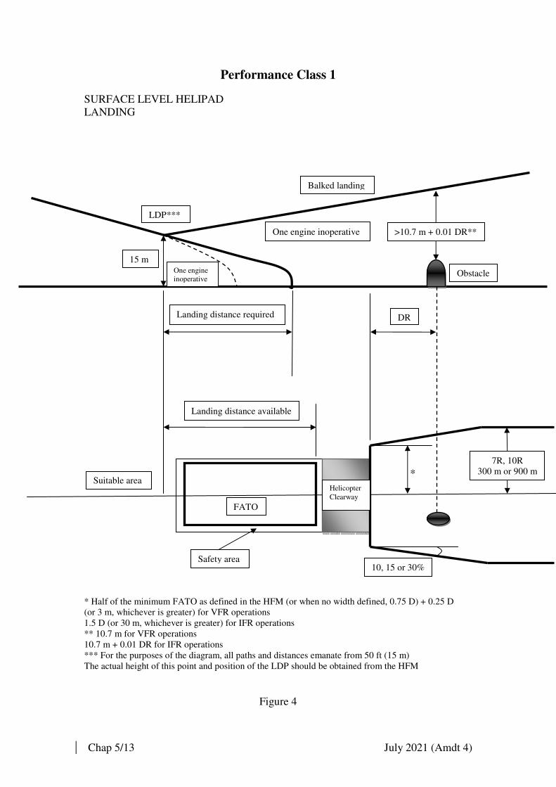
Chap 5/13 July 2021 (Amdt 4)
Performance Class 1
SURFACE LEVEL HELIPAD
LANDING
* *
* Half of the minimum FATO as defined in the HFM (or when no width defined, 0.75 D) + 0.25 D
(or 3 m, whichever is greater) for VFR operations
1.5 D (or 30 m, whichever is greater) for IFR operations
** 10.7 m for VFR operations
10.7 m + 0.01 DR for IFR operations
*** For the purposes of the diagram, all paths and distances emanate from 50 ft (15 m)
The actual height of this point and position of the LDP should be obtained from the HFM
Figure 4
LDP***
One engine
inoperative
One engine inoperative
Balked landing
>10.7 m + 0.01 DR**
15 m
Obstacle
Landing distance required DR
Landing distance available
FATO
Helicopter
Clearway
7R, 10R
300 m or 900 m Suitable area
10, 15 or 30% Safety area

Chap 5/14 July 2021 (Amdt 4)
PERFORMANCE CLASS 1
ELEVATED HELIPORT/HELIDECK
LANDING
* Half of minimum FATO width defined in the HFM (or when no width defined, 0.75 D) + 0.25 D
(or 3 m, whichever is greater) for VFR operations
1.5 D (or 30 m, whichever is greater) for IFR operations
** 10.7 m for VFR operations
10.7 m + 0.01 DR for IFR operations
*** For the purpose of the diagram, all paths and distances emanates from 50 ft (15 m)
The actual height of this point and position of the LDP should be obtained from the HFM
Figure 5
LDP**
Balked landing, all engines operating Balked landing
One engine inoperative
>10.7 m + 0.01 DR**
15 m
4.5 m
DR Landing distance required
Landing distance available
Obstacle
*
7R, 10R
300 m or 900 m
FATO
Safety area
10, 15 or 30%

Chap 5/15 July 2021 (Amdt 4)
9. Operations in performance Class 2
9.1. Take-off and climb phase. The helicopter shall be able, in the event of the
failure of the critical power-unit at any time after reaching DPATO, to
continue the take-off, clearing all the obstacles along the flight path by an
adequate margin until the helicopter is in a position to comply with 9.4. Before
the DPATO, failure of the critical power-unit may cause the helicopter to
force-land. Therefore the condition that appropriate consideration be given to
achieve a safe forced landing applies.
9.2. Take-off. (Figure 6 and 7). The mass of the helicopter at take-off should not
exceed the maximum take-off mass specified in the flight manual for the
procedures to be used and to achieve a rate of climb of 150 ft per min at 300 m
(1000 ft) above the level of the heliport with the critical power-unit
inoperative and the remaining power-units operating at an appropriate power
rating, taking into account the parameters specified in 4.3.
9.3. Take-off flight path. From DPATO or, as an alternative, no later than 60 m
(200 ft) above the take-off surface with the critical power-unit inoperative, the
conditions of 8.3.1 and 8.3.2. should be met.
9.4. En route. The requirement of 8.4. should be met.
9.5. Approach, landing and balked landing (Figure 8 and 9). In the event of the
failure of the critical power-unit before the DPBL, the helicopter shall, at the
destination or any alternate, after clearing all obstacles, in the approach path,
be either able to land and stop within the landing distance available or to
perform a balked landing and clear all obstacles in the approach path by an
adequate margin. After the DPBL, failure of the power-unit may cause the
helicopter to force-land. Therefore the condition that appropriate consideration
be given to achieve a safe forced landing applies. The estimated landing mass
at the destination or alternate should be such that:
9.5.1. It does not exceed the maximum landing mass specified in the flight
manual for a rate of climb of 150 ft per min at 300 m (1000 ft) above
the level of the heliport with the critical power-unit inoperative and the
remaining power-units operating at an appropriate power rating, taking
into account the parameters specified in 4.3.
9.5.2. It is possible, in case of a power-unit failure occurring at or before the
DPBL, either to perform a safe forced landing or to overshoot, meeting
the requirements of 8.3.1. and 8.3.2.
Only obstacles specified in 6. should be considered.

Chap 5/16 July 2021 (Amdt 4)
Performance Class 2 SURFACE LEVEL HELIPORT TAKE-OFF
*
* 0.75 D +0.25 D (or 3 m, whichever is greater) for VFR operations
1.5 D (or 30 m, whichever is greater) for IFR operations
** 10.7 m for VFR operations
10.7 m + 0.01 DR for IFR operations
*** Only the all engines-operating flight path is shown
Figure 6
All engines operating***
Defined point
after take-off
Normal take-off
>10.7 m + 0.01 DR**
One engine inoperative
Obstacle
DR
Area permitting safe forced landing
VMC required IMC possible
Take-off distance available
DPATO
FATO
Safety area
Helicopter
clearway
7R, 10R
300 m or 900 m
10, 15 or 30%

Chap 5/17 July 2021 (Amdt 4)
PERFORMANCE CLASS 2
ELEVATED HELPORT/HELIDECK
TAKE-OFF
*
* 0.75 D +0.25 D (or 3 m, whichever is greater) for VFR operations
1.5 D (or 30 m, whichever is greater) for IFR operations
** 10.7 m for VFR operations
10.7 m + 0.01 DR for IFR operations
*** Only the all engines-operating flight path is shown
Figure 7
All engine operating***
Defined point
After take-off
Normal take-off
One engine inoperative
Obstacle
DR
VMC required IMC possible
Area permitting a safe forced landing
7R, 10R
300 m or 900 m
DPATO
FATO
Safety Area
10, 15 or 30%
>10.7 m + 0.01 DR**

Chap 5/18 July 2021 (Amdt 4)
Performance Class 2
SURFACE LEVEL HELIPORT
LANDING
** *
* 0.75 D +0.25 D (or 3 m, whichever is greater) for VFR operations
1.5 D (or 30 m, whichever is greater) for IFR operations
** 10.7 m for VFR operations
10.7 m + 0.01 DR for IFR operations
Figure 8
Defined point before landing
Balked landing, all engines operating or critical engine failure prior to DPBL
One engine
inoperative
Normal landing
>10.7 m + 0.01 DR**
Obstacle
DR
Landing distance available Area permitting a
Safe forced landing
7R, 10R
300 m or 900 m
FATO
Safety area
10, 15 or 30%

Chap 5/19 July 2021 (Amdt 4)
Performance Class 2
ELEVATED HELIPORT/HELIDECK
LANDING
*
* 0.75 D +0.25 D (or 3 m, whichever is greater) for VFR operations
1.5 D (or 30 m, whichever is greater) for IFR operations
** 10.7 m for VFR operations
10.7 m + 0.01 DR for IFR operations
Figure 9
Balked landing, all engines operating or critical engine failure prior to defined point before landing
DPBL
Normal landing
>10.7 + 0.01 DR VY
Area
permitting
a safe
forced
landing
Obstacle
DR
Landing Distance
available
FATO
Safety area
7R, 10R
300 m or 900 m
10, 15 or 30%

Chap 5/20 July 2021 (Amdt 4)
10. Operations in performance Class 3
10.1. Take-off and initial climb phase. At any point of the flight path, failure of a
power-unit will cause the helicopter to force-land. Therefore the condition that
appropriate consideration be given to achieve a safe forced landing applies.
10.2. Take-off. The mass of the helicopter at take-off should not exceed the
maximum take-off mass specified in the flight manual for a hover in ground
effect with all power-units operating at take-off power, taking into account
parameters specified in 4.3. If the conditions are such that a hover in ground
effect is not likely to be established, the take-off mass should not exceed the
maximum mass specified for a hover out of ground effect with all power-units
operating at take-off power, taking into account the parameters specified in
4.3.
10.3. Initial climb. The take-off mass should be such that the climb path provides
adequate vertical clearance above all obstacles located along the climb path,
all engines operating.
10.4. En route. The take-off mass is such that it is possible to achieve the minimum
flight altitudes for the route to be flown, all engines operating. At any point of
the flight path, failure of a power-unit will cause the helicopter to force-land.
Therefore the condition that appropriate consideration be given to achieve a
safe forced landing applies.
10.5. Approach and landing. At any point of the flight path, failure of a power-unit
will cause the helicopter to force-land. Therefore the condition that
appropriate consideration be given to achieve a safe forced landing applies.
The estimated landing mass at the destination or alternate should be such that:
10.5.1.1. It does not exceed the landing mass specified in the flight manual
for a hover in ground effect with all power-units operating at take-
off power, taking into account the parameters specified in 4.3. If
conditions are such that a hover in ground is not likely to be
established, the take-off mass should not exceed the maximum
mass specified in a hover out of ground effect with all power-units
operating at take-off power, taking into account the parameters
specified in 4.3.
10.5.1.2. It is possible to perform a balked landing, all engines operating, at
the point of the flight path and clear all obstacles by an adequate
vertical interval.

Chap 6/1 June 2018 (Amdt 3)
Chapter 6 - Helicopter – Public Transport Flights in VMC at
Night
1. Minimum Weather and Associated Requirements for Public Transport
Flights in VMC at Night
1.1. In Hong Kong, an aircraft flying at night shall be flown in accordance with the
IFR unless it is within control zone on a Special VFR flight.
1.2. Commercial pilots shall not, unless their license includes an Instrument Rating
validated by a IMC Proficiency Check, fly for the purpose of Public Transport
other than in VMC, and shall not fly as pilot in command at night in VMC
unless they have a minimum of 300 hours total flight time on helicopters
which includes 100 hours as pilot-in-command and 10 hours at night as pilot
flying.
1.3. Further requirements are:
1.3.1. Composition of crew: two pilots, or single pilot for helicopters
equipped with an autopilot with at least altitude hold and heading
mode which is serviceable on take-off and having a maximum total
weight authorized of 5700 kg or less.
1.3.2. Recency: at least 3 take-offs, three circuits and three landings at night
in the preceding 90 days.
1.3.3. Training and checking requirements for single pilot night VMC
operations (which includes a night Proficiency Check, an instrument
qualification, and a night line check) are detailed in Chapter 8.
1.4. Operations manuals must specify weather minima for VMC night flights.
There are two standards of minima which are based on whether the
crew/helicopter combination:
1.4.1. Is not equipped and capable of intentionally entering IMC flight; or
1.4.2. Is equipped and capable of entering IMC and subsequently making
either an instrument approach to an airfield or regaining VMC.
1.5. For a crew/helicopter combination to be considered as IMC capable, the crew
must be qualified for flight in IFR (instrument rating with appropriate training
and checking), the AOC operations manual must include IFR operations, the
aircraft must be equipped for IFR flight, and the weather and fuel state must
be suitable for the flight or any required diversion. If any element is not valid,
the crew/helicopter combination is not considered to be IMC capable.
1.6. For night flight in VMC with visual ground reference, the aircraft altitude
must be capable of being assessed by reference to a clearly distinguishable
external horizon that may be provided either by natural lighting or artificial
lights spread deeply and widely across the track.

Chap 6/2 June 2018 (Amdt 3)
1.7. Night Weather Limits
1.7.1. Non-IMC Capable: For a non-IMC capable crew/helicopter
combination flying in VMC at night by visual ground reference, the
visibility shall not be less than 5 km and the forecast cloud base for the
route shall not be less than 1500 ft above the highest terrain within 5
nm of the route. If the weather deteriorates en-route below the
specified minima, the helicopter shall divert, return to the place of
departure.
1.7.2. IMC Capable: For an IMC capable crew/helicopter combination
flying in VMC at night by visual ground reference, the visibility shall
not be less than 5 km and the forecast cloud base for the route shall not
be less than 1200 ft above the highest terrain within 5 nm of the route.
If the weather deteriorates en-route below the specified minima, the
helicopter shall divert, return to the place of departure or continue the
flight in IMC.
1.7.3. Reduce weather limits may be acceptable in some very specific areas
of operation, such as flight over wholly within the confines of a well
illuminated urban area or well illuminated line feature and also for
some local areas, associated with the company operating base.
Therefore, operators demonstrating an equivalent level of safety may
be permitted some relaxation in the weather criteria stated, provided
the case is acceptable to the HKCAD and the appropriate instructions
are contained in the company operations manual.
Note. The weather limits of Para 1.7 applies to Public Transport
operations only, and do not apply to Law Enforcement and Emergency
Medical Services, where a risk analysis will have to be carried out
taking into consideration the special equipment used, the training of
the crew and the local environment. The weather limits determined by
the risk analysis is to be acceptable to the HKCAD.
1.7.4. If public transport flights in VMC at night are to be conducted outside
the requirements as set out in this chapter, the CAD is to be consulted
at the earliest opportunity to determine whether equivalent safety
measures can be applied that would allow the flights to be carried out
under specified conditions.

Chap 7/1 June 2018 (Amdt 3)
Chapter 7 - Miscellaneous Provisions Affecting Helicopter
Operations
1. Loading Instructions
1.1. Helicopter operators must provide loading instructions suited to the
capabilities, limitations and operation of a helicopter. In preparing these
instructions operators should remember that in many cases they will have to be
read and implemented by personnel with little or no aviation experience, such
as oil rig crews and contractors’ staff. The instructions should be clear, concise
and avoid the use of aviation jargon.
2. Radio Altimeter (Height Bug Setting Procedures)
2.1. Radio Altimeter (Radalt) and Audio Voice Alerting Devices (AVADs) for
Public Transport over water operations are mandatory and the requirements
were introduced with a warning of the proximity of the helicopter to the
surface of the sea, sufficiently early so as to alert the crew and enable them to
conduct corrective action.
2.2. It is essential that, for flights for which there is an equipment requirement for a
radio altimeter to be fitted, the operations manual contains a procedure for
setting the height bug or equivalent decision height indicator. The procedure
should recognize the prime function of selecting the height indicator is to give
the pilot early warning of possible impact with the sea and therefore when
formulating the procedure, operators should ensure that the procedure gives
their pilots “adequate” warning/reaction time. There are numerous instances of
helicopter flights being conducted over-water where the fitment of a radio
altimeter is not mandatory but where one is nonetheless installed. Operators of
these flights should consider the safety benefits of providing advice to their
crews on setting height warning bugs in such circumstances.
3. Provision of Two-Way Communications during Underslung Load
Operations
3.1. The safety and efficiency of any load carrying operation depends to a large
extent on the proficiency and team work of the ground personnel and this can
be considerably enhanced by the use of portable VHF radios. This is
particularly helpful when another crew member is not on board the helicopter
to monitor the behavior of the external load. Operators should consider the use
of two-way radio communications with the Ground Team when appropriate to
the circumstances of the task, and should include a section in their operations
manual detailing the procedures for the use of this two-way communication.

Chap 7/2 June 2018 (Amdt 3)
4. The Wearing of Protective Helmets by Crew Members Engaged in
Underslung Load Operations
4.1. Operators are recommended to implement procedures requiring all crew
members to wear protective flying helmets when conducting underslung load
operations.
5. Special Protective Equipment: Power Line Inspections
5.1. Some AOC holders exercise the privileges of Exemptions against Schedule
14, Rules of the air Regulations, Rule 5(1)(e), on a regular and medium basis,
for the purpose of inspecting, repairing and maintaining overhead transmission
lines. The exemptions are subject to conditions designed to afford protection
to vessels and vehicles unconnected with the task in hand and to persons and
property on the surface. The standard Exemption does not directly address the
risk to the helicopter and its occupants since it is assumed that the flight will
not take place within the avoid section of the appropriate height/velocity
graph.
5.2. It must be stressed that when non-company personnel are carried, these flights
are classified as Public Transport, and as such, passengers are to be afforded
proper protection. This means that planned flights in the avoid section of the
height/velocity avoid area must be avoided. If prolonged penetration of the
height /velocity avoid area are unavoidable as, for example, in live-line work,
a twin-engined helicopter with the appropriate performance should be
employed for the task. Where it is considered suitable to use a Group B
helicopter it will often be the case that the terrain, onto which a forced landing
may have to be carried out, will be unsuitable in terms of slope, for instance,
to ensure full public transport protection standards to the passengers. In
recognition of this unusual risk it is necessary for operators to afford the
aircraft occupants added compensatory protection by requiring:
5.2.1. Aircraft engaged on the task to be equipped with full restraint harness
for each occupant;
5.2.2. Each occupant to wear a protective helmet; and
5.2.3. Each occupant to wear flame proof overalls and clothing (and suitable
footwear).
6. Additionally AOC holders should brief all personnel engaged on the task of
any additional hazards associated with this type of flight, the material for such
briefing to be included in the operations manuals. Initial grant and renewal of
Exemptions will be conditional on meeting these requirements.

Chap 7/3 June 2018 (Amdt 3)
6. Loss of Tail Rotor Effectiveness
6.1. A critical low speed aerodynamic flight condition that results in an
uncommanded rapid yaw rate that does not subside and which results in the
loss of a helicopter if it remains unchecked is described as Loss of Tail Rotor
Effectiveness (LTE). LTE results from a control margin deficiency and not a
maintenance malfunction. LTE is an aerodynamic condition that can affect all
single rotor helicopters that utilize a conventional tail rotor.
6.2. Whilst the design of the main and tail rotor blades and tail boom assembly can
affect the characteristics and susceptibility of a helicopter to LTE, it will not
nullify the phenomenon entirely. Tail Rotor capability is a factor and a
helicopter type that is prone to reaching full pedal when, for example,
hovering out of wind Inside Ground Effect (IGE) is more likely to suffer LTE
due to high power (high, but in limits, gearbox torque or engine power) than a
helicopter with good pedal margins in the same situation. Pilots should be
aware of the characteristics of the helicopter they fly and be particularly aware
of the amount of tail rotor pedal typically required for different flight
conditions. LTE can occur on helicopters with either anti-clockwise or
clockwise rotating main blades, but the direction of the relative wind that
makes them susceptible to LTE will differ. Thus an American design will be
susceptible with the relative wind from the left front arcs, and the French
designs will be susceptible with relative winds from the front right arcs.
6.3. LTE is a condition that occurs when the flow of air through a conventional tail
rotor, is altered in some way, by altering either the angle or the speed which
the air passes through the rotating blades of the tail rotor system. An effective
tail rotor relies on a stable and relatively undisturbed airflow in order to
provide a steady and constant anti-torque reaction. The pitch, and inevitably
the angle of attack of the individual blades, will determine the thrust output of
the tail rotor. A change to any of these criteria, will inevitably alter the amount
of thrust generated. When a pilot, makes a yaw pedal input he will effect a
thrust reaction from the tail rotor. Altering the thrust delivered from the same
yaw input will create an in-balance. Taking this in-balance to the extreme will
result in the loss of effective control in the yawing plane and LTE will occur.
The alteration of the tail rotor thrust can be effected by numerous external
influences. The main influence and hence the main contributing factors of
LTE are:
6.3.1. Airflow and downdraft generated by the main rotor blades interfering
with the airflow entering the tail rotor assembly;
6.3.2. Main rotor vortices developed in the main rotor tips entering the tail
rotor; and
6.3.3. Turbulence and other natural phenomena affecting the airflow
surrounding the tail rotor.

Chap 7/4 June 2018 (Amdt 3)
6.4. Wind tunnel tests have shown that the aerodynamic turbulence induced with
all three of the above phenomena are both complex and interrelated; however,
three conditions appear to be contributory factors of LTE:
6.4.1. A high power setting, hence large main rotor pitch angle, induces
considerable main rotor blade downwash and hence more turbulence
than when the helicopter is in a low power setting;
6.4.2. A slow forward speed, typically at speeds where translational lift is in
the process of change, where airflow around the tail rotor will vary in
direction and speed; and
6.4.3. The airflow relative to the helicopter, the worst case being when the
relative wind is within + or – 15 degrees of the 10 or 2 o’clock position
(American/French types respectively) when the generated vortices can
be blown directly into the tail rotor.
6.5. Certain flight activities are more at high risk to LTE than others and can find
themselves in low and slow situations over the geographical areas where the
exact wind speed and direction are hard to determine; power-line and pipeline
patrol sectors, low speed aerial filming, and in Police and Air Ambulance
service environments.
6.6. The exact parameters described below will vary from type to type depending
on rotor orientation (clockwise or anti), the size of the machine and the
geometric and aerodynamic relationship between the main and tail rotors.
However there are certain flight phases where LTE is more likely to occur
regardless of the type. The following is a general ‘how to avoid LTE’ list and
whenever possible, avoid combinations of:
6.6.1. Low and slow flight outside of ground effect;
6.6.2. Winds from + or – 15 degrees or the 10 o’clock (American) or
2 o’clock (French) position;
6.6.3. Tailwinds that may alter the onset of translational lift hence induce
high power demands;
6.6.4. Low speed downwind turns;
6.6.5. Large changes of power at low airspeeds; and
6.6.6. Low speed flight in the proximity of physical obstructions that may
alter a smooth airflow.
6.7. Pilots should be aware that if they enter a flight regime where combinations of
the above occurred, then they are entering a potential LTE situation. In this
case they should realize the possibility of experiencing LTE, recognize their
onset and be prepared to react quickly before it builds up.
6.8. The exact actions to be taken, having encountered the phenomenon, will vary
according to the circumstances, but gaining forward airspeed will remove the
problem. Awareness of LTE to assist in early detection of it, followed by firm
corrective action to counter the effect, will always pay dividends. Early
identification followed by the immediate application of corrective action by
Chap 7/5 June 2018 (Amdt 3)
getting the nose forward to regain airspeed is the key to a safe recovery –
hence the need for the pilot to ensure that he has the height and space available
to recover.
6.9. Vortex ring state can also occur on the tail rotor if the tail rotor thrust is
opposed by a sufficiently strong airflow. In helicopters with counter-clockwise
rotating main rotors, tail rotor thrust is produced by air being drawn from the
right and accelerated to the left. Thus, if an airflow is present from left to right
onto the tail rotor, vortex ring state can develop. Such an opposite airflow may
occur when the aircraft is subject to a high rate hover turn to the right, wind
from the left, or sideways flight to the left. The problem shows up when the
rate of turn suddenly increases. If the pilot uses full left anti-torque pedal to
stop the turn it may place substantial stresses on the drive system because the
angles of attack on the tail rotor blades rapidly becomes exceedingly large.
This together with the reduction of the induced flow due to the opposing
airflow from the turn to the right will result in an extremely large angle of
attack, that may approach the stalling angle of attack.
6.10. There was a case where a counter-clockwise rotating main rotors helicopter,
hovering downwind, in ground effect, made a rapid yaw turn to the right.
When the pilot applied full left pedal to stop the turn when he was into wind,
the rate of turn to the right increased. The pilot could not arrest the rate of turn,
in fact the full application of left pedal accelerated the turn to the right.
According to the helicopter’s Pilot’s Handbook, this indicates a Loss of Tail
Rotor Thrust and the action to be taken is to roll off the throttle to remove the
helicopter’s anti-torque effect and cushion the landing by the application of
collective. To prevent this occurring, all hover manoeuvres should be carried
out at a slow controlled pace.
7. One-Engine-Inoperative Ferry Flights – Helicopters
7.1. General
7.1.1. A one-engine-inoperative ferry flight in a multi-engined helicopter
should only be considered under the most exceptional circumstances.
The same general criteria and limitations that apply to aeroplane one-
engine-inoperative ferry flights should be followed where appropriate.
(see Appendix D, Chapter 4 of CAD 360)
7.1.2. A one-engine-inoperative ferry flight is not permitted unless the
limitations, performance and operational procedures are specified in
the helicopter’s Flight Manual and the instructions pertaining to such a
flight are included in the company’s Operational Manual.
8. Turning of Helicopter Rotor under Power
8.1. A helicopter rotor shall not be turned under power without a qualified pilot at
the controls.

Chap 7/6 June 2018 (Amdt 3)
9. Offshore Operations
9.1. Helicopters operating in Performance Class 1 or 2 shall be equipped with:
9.1.1. One life jacket, for each person. The life jacket shall be worn
constantly unless the occupant is wearing an integrated survival suit
that includes the functionality of the life jacket.
9.1.2. A survival suit, for each person. The survival suit should be worn by
all occupants when the sea temperature is less than 10 degrees
centigrade or when the estimated rescue time exceeds the calculated
survival time. When the elevation and strength of the sun results in a
high temperature hazard on the flight deck, consideration should be
given to alleviating the flight crew from this recommendation.

Chap 8/1 June 2018 (Amdt 3)
Chapter 8 - Additional Factors for Helicopter Pilots’ Training and
Periodic Test
1. Introduction
1.1. The periodic test for helicopter pilots should be based, as far as it is
practicable to do so for aeroplane pilots in Chapter 5 of CAD 360.
1.2. Commanders and co-pilots should normally be checked in their respective
seats.
1.3. Commanders whose duties also require them to carry out the duties of the co-
pilot, or commanders required to conduct training or examining duties, shall
complete their proficiency checks respectively from left and right hand seats,
on alternate proficiency checks.
2. Line Checks
2.1. Operator’s, training staff should recognize the wide variety of roles in which
pilots may be engaged and the content of the line check should reflect this. In
any event the duration of the line check should not be less than 40 minutes.
2.2. Conduct of the line check must closely follow the requirements of CAD 360,
Part 1, Chapter 5, paragraph 9.5. For pilots who are required to operate at
night or under IMC the check must include an appropriate section and
certification. The airways section of the instrument rating renewal may be
counted as satisfying the IMC requirement.
3. Proficiency Checks
3.1. The proficiency check provides an opportunity for the practice of emergency
drills and procedures which rarely arise in normal operations, and can
generally be regarded as continuation training. The statutory Schedule 9
requirements, however, is that pilots shall be tested. And their continued
competence must be verified and certified. It includes renewal of the Aircraft
Rating (i.e. > boxed items = of form DCA 528) and, where applicable,
Instrument Rating. Some manoeuvres can only be conducted in VMC whilst
others must be carried out in simulated IMC (either by use of approved blind-
flying screens or a simulator approved for this purpose). Those pilots
conducting only VMC operations normally need only carry out a VMC
section. Those required to carry out both VMC and IMC operations will
require both VMC check and an IMC check. It is therefore acceptable to treat
these sections as separate checks each having the same validity as prescribed
at CAD 360, Part One, Appendix A to Chapter 5.
3.2. Those items of the VMC check which are appropriate at night operations and
those which should only be attempted in daylight should be checked at least
annually. Therefore the VMC check should be conducted alternately by day
and night.

Chap 8/2 June 2018 (Amdt 3)
3.3. The content of the VMC proficiency check must include the following items
where applicable to the type of helicopter:
3.3.1. Engine failure before and after the decision point for each take-off
profile and each landing profile that is in use by the operator and is
published in the Operations Manual;
3.3.2. Flight and engine control systems malfunctions for which accepted
procedures are included in the Rotorcraft Flight Manual;
3.3.3. Auto-rotation to a designated area with powered recovery to forward or
hovering flight; and
3.3.4. Pilot incapacitation.
3.4. The content of the IMC proficiency check must include the following items
where applicable to the type of helicopter:
3.4.1. Precision instrument approach to minima with, in the case of multi-
engined helicopters, a simulated failure of one engine;
3.4.2. Non-precision approach to minima;
3.4.3. Where appropriate to the helicopter type, approach with flight control
system/flight director system malfunction, flight instrument and
navigation equipment failures;
3.4.4. At least one instrument approach should be flown with a degradation
of the flight control system/auto-pilot; and
3.4.5. Recovery from unusual attitudes and techniques for auto-rotation in
IMC.
3.5. Emergencies such as tail rotor failure, double engine failure, and icing
problems which it would be impossible or only possible with acceptable risk
factor to practise in flight, should be covered in a simulator or by discussion
on the ground.
4. Conduct of Specialist Task Checks
4.1. Contract work will often require specialist techniques, and operators should
ensure that role checks can be conducted to cover particular circumstances.
Examples of these are:
4.1.1. Manoeuvres in confined areas or over rough or uneven ground
4.1.2. Over water operations, including winching
4.1.3. Underslung loads
4.1.4. Power line “stringing”
Chap 8/3 June 2018 (Amdt 3)
5. Instrument Approach Proficiency
To satisfy the requirements for Commander’s and co-pilot’s instrument
approach proficiency, at least one instrument approach must be flown in IMC
(actual or simulated). This approach must be carried to a position from which
a successful landing could have been made and this will normally form part of
the proficiency check.
6. Instrument Rating (Helicopters)
The helicopter Instrument rating is valid only in respect of the helicopter type
on which the test was conducted with the exception of the airways section
which need only be conducted on one type in the case of a multi-type rated
pilot.
7. Proficiency Checks – Pilots to Operate at Night in VMC
7.1. Two Pilot Operation. For helicopters that are operated by two pilots, each
holding a valid Instrument Rating (IR) and IMC Proficiency Check, there are
no specific requirements for Proficiency Checks to be carried out at night.
However, companies must examine their night operating procedures, and if
night performance profiles, e.g. helipad and deck operations, require
procedures or techniques that are unique to the night environment, then
appropriate training and alternating day/night Proficiency Checks must be
incorporated into the recurrent training and checking programme. For pilots
without a valid Instrument Rating and VMC Proficiency Check an Instrument
Night Qualification (INQ) previously referred to as Night Qualification Check
(NQC) and night Proficiency Check requirement are the same as detailed in
paragraphs 7.2. and 7.3. for single pilot operation.
7.2. Single-Pilot Operation. To operate single pilot night in VMC, the pilot must
hold either a valid IR and IMC Proficiency Check or an INQ. Pilots who do
not hold an IR and IMC Proficiency Check are required to demonstrate their
competence while executing specified manoeuvres and procedures in flight in
simulated instrument flight conditions, prior to commencing night operations
in VMC, and thereafter at six monthly intervals. The training and checking
syllabus for the INQ is detailed in Appendix 1 to this Chapter. The INQ must
not be confused with, and in addition to, the requirement for a Proficiency
Check to be carried out at night, detailed in paragraph 7.3. below.
7.3. Prior to commencing night operations in VMC, Pilots shall carry out a
Proficiency Check at night. Thereafter, each alternate Proficiency Check shall
be conducted at night. A Proficiency Check conducted at night shall qualify a
pilot for both day and night operations.

Chap 8/4 June 2018 (Amdt 3)
8. Operations to Oil and Gas Installations and Vessels at Night
8.1. Operators who intend to work in the offshore environment to oil and gas
installations shall ensure that all pilots are initially qualified in night deck
landings and thereafter remain recent.
8.2. An initial night deck landing qualification will qualify a pilot to land on and
depart from an installation at night. The qualification shall be valid for 12
months and may be revalidated by operating to a deck at night within the 12
month period. A pilot whose night deck recency has expired may operate to a
deck at night provided he is in date for day deck landings and is accompanied
by a suitably qualified Line Training Captain.

Chap 8/5 June 2018 (Amdt 3)
Appendix 1 to Chapter 8
Training and Checking Required for a Public Transport Helicopter
Night Qualification for Flight Crew who do not hold an IR or IMC
Proficiency Check
1. Introduction
1.1. The training and checking requirements and skill levels necessary of a
helicopter Instrument Night Qualification (INQ) are listed below. The INQ is
only required by flight crew whose license does not include an instrument
rating which has been validated by an Instrument Proficiency Check and who
carries out Public Transport or Commercial Air Transport at night in VMC.
1.2. The pilot conducting the training and/or checking (the Training Captain) shall
be a Type Rating Examiner for the aircraft type to be used. The pilot under test
shall pass all section of the INQ. Failure in more than one section will require
the pilot to take the entire check again. A pilot failing only one section shall
take the failed section again. Further training may be required following any
failed INQ. Failure to achieve a pass in all sections of the check in two
attempts shall require further training as determined by the examiner.
1.3. The INQ is type-specific, and shall be carried out in the helicopter type in
flight.
2. Conduct of Check
2.1. The check is intended to simulate a practical flight and should be carried out in
Day VFR under simulated instrument flight conditions. The route to be flown
shall be chosen by the Training Captain. An essential element is the ability of
the pilot to plan and conduct the flight from routine briefing material. The
pilot shall undertake the flight planning and shall ensure that all equipment
and documentation for the execution of the flight are on board. The duration of
the flight shall be at least 30 minutes.
2.2. The pilot shall normally be required to fly the helicopter from a position where
pilot-in-command functions can be performed and to carry out the check as if
there is no other crew-member. The Training Captain shall take no part in the
operation of the helicopter, except when intervention is necessary in the
interests of safety or to avoid unacceptable delay to other traffic. The pilot
shall indicate to the Training Captain the checks and duties carried out,
including the identification of radio facilities. Checks shall be completed in
accordance with the authorized checklist for the helicopter on which the check
is being taken. Power settings and speeds should be agreed with the Training
Captain before the start of the check and should normally conform to those
given in the operations or flight manual of the helicopter concerned.

Chap 8/6 June 2018 (Amdt 3)
3. Flight Check Tolerances
3.1. The pilot shall demonstrate the ability to:
3.1.1. Operate the helicopter within its limitations;
3.1.2. Complete all manoeuvres with smoothness and accuracy;
3.1.3. Exercise good judgement and airmanship;
3.1.4. Apply aeronautical knowledge; and
3.1.5. Maintain control of the helicopter at all times in such a manner that the
successful outcome of a procedure is never in doubt.
3.2. The following limits are for general guidance. The Training Captain shall
make allowance for turbulent conditions and the handling qualities and
performance of the helicopter used.
Height: +/- 150 ft
Heading: +/- 10 degrees
Speed: +/- 10 knots
4. Contents of INQ
Section 1
Pre-Departure
(a) Aircraft performance calculation, mass and balance
(b) Pre-flight inspection
(c) Knowledge of OM weather minima requirements
(d) Pre-take-off instrument serviceability checks
Section 2
General Handling
(coupled autopilot modes may not be used in this section)
Control of the helicopter by reference solely to instruments, including:
(a) Transition to instrument flight during climb out;
(b) Climbing and descending turns with sustained Rate 1 bank angle;
(c) Speed changes in level flight maintaining a constant heading and altitude;
(d) Rate 1 turns to specific headings maintaining a constant altitude;
(e) Autorotation and recovery to level flight;
Chap 8/7 June 2018 (Amdt 3)
(f) Limited panel (main Attitude Indicator failure); and
(g) Recovery from unusual attitudes, to include: Low IAS and High rate of
descent; High IAS; High bank angles.
Section 3
Emergency Homing and Let Down Procedure
(coupled autopilot mode, if fitted, may be used for this section)
Control of the helicopter by reference solely to instruments, including:
(a) Setting and checking of navigational aids, identification of facilities if
applicable;
(b) Homing to a nominated point, as briefed by the Training Captain, using
pilot interpreted aids or simulated ground instructions;
(c) Level flight, control of heading, altitude and airspeed, power setting;
(d) Altimeter settings;
(e) ATC liaison and compliance, (simulated if appropriate) RTF procedures;
and
(f) Instrument let down to an airfield as briefed by the Training Captain (can
be by use of pilot interpreted aids or ground instructions which may be
simulated).

Chap 8/8 June 2018 (Amdt 3)
INTENTIONALLY LEFT BLANK

Chap 8/9 June 2018 (Amdt 3)
Appendix 2 to Chapter 8
Low Visibility Operations – Training and Qualifications
1. General. An operator must ensure that the flight crew member training
programmes for Low Visibility Operations include structured courses of
ground, flight simulator and/or flight training. The operator may abbreviate the
course content as prescribed in sub-paragraph 1.2. and 1.3. below provided the
content of the abbreviated course is acceptable to the HKCAD.
1.1. Flight crew members with no Category II or III experience must complete the
full training programme prescribed in sub-paragraph 2., 3., and 4. below.
1.2. Flight crew members with Category II and III experience may undertake an
abbreviated ground training course.
1.3. Flight crew members with Category II or III experience with the operator may
undertake an abbreviated ground, flight simulator and/or flight training course.
The abbreviated course is to include at least the requirements of sub-
paragraphs 4.1., 4.2.1., or 4.2.2., as appropriate and 4.3.1.
2. Ground Training. An operator must ensure that the initial ground training
course for Low Visibility Operations covers at least:
2.1. The characteristics and limitations of the ILS and/or MLS
2.2. The characteristics of the visual aids
2.3. The characteristics of fog
2.4. The operational capabilities and limitations of the particular airborne system
2.5. The effects of precipitation, ice accretion, low level wind shear and turbulence
2.6. The effects of specific helicopter malfunctions
2.7. The use and limitations of RVR assessment systems
2.8. The principles of obstacle clearance requirements
2.9. Recognition and action to be taken in the event of failure of ground equipment
2.10. The procedures and precautions to be followed with regard to surface
movement during operations when the RVR is 400 m or less and any
additional procedures required for take-off in condition below 150 m
2.11. The significance of Decision Heights based upon radio altimeters and the
effect of terrain profile in the approach area on radio altimeter readings and on
the automatic approach/landing systems
2.12. The importance and significance of Alert Height if applicable and the action in
the event of any failure above and below the alert height
2.13. The qualification requirements for pilots to obtain and retain approval to
conduct Low Visibility Take-offs and Category II and III operations
2.14. The importance of correct seating and eye position

Chap 8/10 June 2018 (Amdt 3)
3. Flight simulator training and/or flight training
3.1. An operator must ensure that flight simulator and/or flight training for Low
Visibility Operations includes:
3.1.1. Checks of satisfactory functioning of equipment, both on the ground
and in flight.
3.1.2. Effect of minima caused by changes in the status of ground
installations.
3.1.3. Monitoring of automatic flight control systems and auto-land status
annunciators with emphasis on the action to be taken in the event of
failures of such systems.
3.1.4. Action to be taken in the event of failures such as engines, electrical
systems, hydraulics or flight control system.
3.1.5. The effect of known unserviceability and use of minimum equipment
lists.
3.1.6. Operating limitations resulting from airworthiness certification.
3.1.7. Guidance on the visual cues required at decision height together with
information on maximum deviation allowed from glidepath or
localizer.
3.1.8. The importance and significance of Alert Height if applicable and the
action in the event of any failure above and below the Alert Height.
3.2. An operator must ensure that each flight crew-member is trained to carry out
his duties and instructed on the coordination required with other crew
members. Maximum use should be made of suitably equipped flight
simulators for this purpose.
3.3. Training must be divided into phases covering normal operations with no
helicopter or equipment failures but including all weather conditions which
may be encountered and detailed scenarios of helicopter and equipment failure
which could affect Category II or III operations. If the helicopter system
involves the use of hybrid or other special systems (such as head up displays
or enhanced vision equipment) then flight crew-members must practice the use
of these systems during the flight simulator phase of training.
3.4. Incapacitation procedures appropriate to Low Visibility Take-offs and
Category II or III operations shall be practiced.
3.5. For helicopters with no type specific flight simulator, operators must ensure
that the flight training phase specific to the visual scenarios of Category II
operations is conducted in a flight simulator approved for the purpose by the

Chap 8/11 June 2018 (Amdt 3)
HKCAD. Such training must include a minimum of 4 approaches. The
training that is type specific shall be practiced in the helicopter.
3.6. Category II and III training shall include at least the following exercise:
3.6.1. Approach using the appropriate flight guidance, autopilots and control
systems installed in the helicopter, to the appropriate decision height
and to include transition to visual flight and landing;
3.6.2. Approach with all engines operating using the appropriate flight
guidance systems, autopilots and control systems installed in the
helicopter down to the appropriate decision height followed by missed
approach, all without external visual reference;
3.6.3. Where appropriate, approaches using automatic flight systems to
provide automatic flare, hover, landing and roll-out; and
3.6.4. Normal operations of the applicable system both with and without
acquisition of visual cues at decision height.
3.7. Subsequent phases of training must include at least:
3.7.1. Approaches with engine failure at various stages of the approach;
3.7.2. Approaches with critical equipment failure (e.g. electrical systems,
autoflight systems, ground and /or airborne ILS/MLS systems and
status monitor);
3.7.3. Approaches where failure of autoflight equipment at low level require
either:
3.7.3.1. Reversion to manual flight to control flare, hover, landing
and roll out or missed approach; or
3.7.3.2. Reversion to manual flight on a degraded automatic mode
to control missed approaches from, at or below decision
height including those which may result in a touchdown on
the runway;
3.7.4. Failure of the systems which will result in excessive localizer and/or
glide-slope deviation, both above and below decision height, in the
minimum visual conditions authorized for the operation. In addition a
continuation to a manual landing must be practiced if a head-up
display forms the only flare mode; and
3.7.5. Failures and procedures specific to helicopter type or variant.
3.8. The training programme must provide practice in handling faults which
require a reversion to higher minima.

Chap 8/12 June 2018 (Amdt 3)
3.9. The training programme must include, the handling of the helicopter when,
during a fail passive Category III approach, the fault causes the autopilot to
disconnect at or below decision height when the last reported RVR is 300 m or
less.
3.10. When take-offs are conducted in RVRs of 400 m or below, training must be
established to cover systems failure and engine failures resulting in continued
as well as rejected take-offs.
4. Conversion training Requirements to conduct Low Visibility Take-off
and Category II and III operations. An operator shall ensure that each flight
crew member completes the following Low Visibility Procedure training if
converting to a new type or variant of helicopter in which Low Visibility
Take-off and Category II and III Operations will be conducted. The flight
crew member experience requirements to undertake an abbreviated course are
prescribed in sub-paragraphs 1.2 and 1.3. above.
4.1. Ground Training. The appropriate requirement prescribes in sub-paragraph 2.
above, taking into account the flight crew member’s Category II and III
training and experience.
4.2. Simulator Training and/or Flight Training
4.2.1. A minimum of 8 approaches and/or landings in a flight simulator
approved for the purpose.
4.2.2. When no type specific flight simulator is available, a minimum of 3
approaches including at least one go-around is required on the
helicopter.
4.2.3. Appropriate additional training if any special equipment is required
such as head-up displays or enhanced vision equipment.
4.3. Flight Crew Qualification. The flight crew qualification requirements are
specific to the operator and the type of helicopter operated.
4.3.1. The operator must ensure that each flight crew member completes a
check before conducting Category II or III operations.
4.3.2. The check provided in sub-paragraph 4.3.1. above may be replaced by
successful completion of the flight simulator and/or flight training
prescribed in sub-paragraph 4.2. above
4.4. Line Flying under Supervision. An operator must ensure that each flight crew
member undergoes the following under supervision:
4.4.1. For Category II when a manual landing is required, a minimum of 3
landings from autopilot disconnect.

Chap 8/13 June 2018 (Amdt 3)
4.4.2. For Category III, a minimum of 3 autolands except that only 1
autoland is required when the training required in sub-paragraph 4.2.
above has been carried out in a full flight simulator usable for zero
flight time training.
5. Type and command experience. The following additional requirements are
applicable to commanders who are new to the helicopter type:
5.1. 50 hours or 20 sectors as pilot-in-command on the type before performing any
Category II or III operations.
5.2. 100 hours or 40 sectors as pilot-in-command on the type. 100 m must be
added to the applicable Category II or III RVR minima unless he has been
previously qualified for Category II or III operations with another operator.
5.3. The HKCAD may authorize a reduction in the above command experience
requirement for flight crew members who have Category II or III command
experience.
6. Low Visibility Take-off with RVR less than 150 m
6.1. An operator must ensure that prior to authorization to conduct take-offs in
RVRs below 150 m the following training is carried out:
6.1.1. Normal take-off in minimum authorized RVR conditions;
6.1.2. Take-off in minimum authorized RVR conditions with an engine
failure at or after TDP; and
6.1.3. Take-off in minimum authorized RVR conditions with an engine
failure before the TDP.
6.2. An operator must ensure that the training required by sub-paragraph 6.1.
above is carried out in an approved flight simulator. This training must include
the use of any special procedures and equipment. Where no approved
simulator exists, the HKCAD may approve such training in a helicopter
without the requirement for minimum RVR conditions.
6.3. An operator must ensure that a flight crew member has completed a check
before conducting low visibility take-offs in RVRs of less than 150 m if
applicable. The check may only be replaced by successful completion of the
flight simulator and/or flight training prescribed in sub-paragraph 6.1. on
initial conversion to a helicopter type.
7. Recurrent Training and Checking – Low Visibility Operations
7.1. An operator must ensure that, in conjunction with the normal recurrent
training and operator proficiency checks, a pilot’s knowledge and ability to
perform the tasks associated with the particular category of operation,
including LVTO, for which he is authorized is checked. The required number
Chap 8/14 June 2018 (Amdt 3)
of approaches to be conducted during such recurrent training is to be a
minimum of two, one of which is to be a missed approach and at least one low
visibility take-off to the lowest applicable minima. The period of validity for
this check is 6 months including the remainder of the month of issue.
7.2. For Category III operations an operator must use a flight simulator approved
for Category III training.
7.3. An operator must ensure that, for Category III operations on helicopter with a
fail passive flight control system, a missed approach is completed at least once
every 18 months as a result of an autopilot failure at or below decision height
when the last reported RVR is 300 m or less.
7.4. The HKCAD may authorize recurrent training for Category II operations in a
helicopter type where no approved flight simulator is available.
8. LVTO and Category II and III Recency Requirements
8.1. An operator must ensure that, in order for pilots to maintain a Category II and
III qualification, they have conducted a minimum of 3 approaches and
landings using approved Category II/III procedures during the previous 6
months period, at least one of which must be conducted in the helicopter.
8.2. Recency for LVTO is maintained by retaining the Category II or III
qualification prescribes in sub-paragraph 8.1. above.
8.3. An operator may not substitute this recency requirement for recurrent training.
*******