cad wor x plant users guide
DESCRIPTION
tutorialTRANSCRIPT

CADWorx Plant User's Guide
Version 2015 (15.0)
August 2014
DICAS-PE-200007D
Copyright Copyright © 2003-2014 Intergraph® Corporation. All Rights Reserved. Intergraph is part of Hexagon.
Including software, file formats, and audiovisual displays; may be used pursuant to applicable software license agreement; contains confidential and proprietary information of Intergraph and/or third parties which is protected by copyright law, trade secret law, and international treaty, and may not be provided or otherwise made available without proper authorization from Intergraph Corporation.
U.S. Government Restricted Rights Legend Use, duplication, or disclosure by the government is subject to restrictions as set forth below. For civilian agencies: This was developed at private expense and is "restricted computer software" submitted with restricted rights in accordance with subparagraphs (a) through (d) of the Commercial Computer Software - Restricted Rights clause at 52.227-19 of the Federal Acquisition Regulations ("FAR") and its successors, and is unpublished and all rights are reserved under the copyright laws of the United States. For units of the Department of Defense ("DoD"): This is "commercial computer software" as defined at DFARS 252.227-7014 and the rights of the Government are as specified at DFARS 227.7202-3.
Unpublished - rights reserved under the copyright laws of the United States.
Intergraph Corporation 300 Intergraph Way Huntsville, AL 35813
Documentation Documentation shall mean, whether in electronic or printed form, User's Guides, Installation Guides, Reference Guides, Administrator's Guides, Customization Guides, Programmer's Guides, Configuration Guides and Help Guides delivered with a particular software product.
Other Documentation Other Documentation shall mean, whether in electronic or printed form and delivered with software or on Intergraph Smart Support, SharePoint, or box.net, any documentation related to work processes, workflows, and best practices that is provided by Intergraph as guidance for using a software product.
Terms of Use a. Use of a software product and Documentation is subject to the End User License Agreement ("EULA") delivered with the
software product unless the Licensee has a valid signed license for this software product with Intergraph Corporation. If the Licensee has a valid signed license for this software product with Intergraph Corporation, the valid signed license shall take precedence and govern the use of this software product and Documentation. Subject to the terms contained within the applicable license agreement, Intergraph Corporation gives Licensee permission to print a reasonable number of copies of the Documentation as defined in the applicable license agreement and delivered with the software product for Licensee's internal, non-commercial use. The Documentation may not be printed for resale or redistribution.
b. For use of Documentation or Other Documentation where end user does not receive a EULA or does not have a valid license agreement with Intergraph, Intergraph grants the Licensee a non-exclusive license to use the Documentation or Other Documentation for Licensee’s internal non-commercial use. Intergraph Corporation gives Licensee permission to print a reasonable number of copies of Other Documentation for Licensee’s internal, non-commercial. The Other Documentation may not be printed for resale or redistribution. This license contained in this subsection b) may be terminated at any time and for any reason by Intergraph Corporation by giving written notice to Licensee.
Disclaimer of Warranties Except for any express warranties as may be stated in the EULA or separate license or separate terms and conditions, Intergraph Corporation disclaims any and all express or implied warranties including, but not limited to the implied warranties of merchantability and fitness for a particular purpose and nothing stated in, or implied by, this document or its contents shall be considered or deemed a modification or amendment of such disclaimer. Intergraph believes the information in this publication is accurate as of its publication date.
The information and the software discussed in this document are subject to change without notice and are subject to applicable technical product descriptions. Intergraph Corporation is not responsible for any error that may appear in this document.
The software, Documentation and Other Documentation discussed in this document are furnished under a license and may be used or copied only in accordance with the terms of this license. THE USER OF THE SOFTWARE IS EXPECTED TO MAKE THE FINAL EVALUATION AS TO THE USEFULNESS OF THE SOFTWARE IN HIS OWN ENVIRONMENT.
Intergraph is not responsible for the accuracy of delivered data including, but not limited to, catalog, reference and symbol data. Users should verify for themselves that the data is accurate and suitable for their project work.
2 CADWorx Plant User's Guide

Limitation of Damages IN NO EVENT WILL INTERGRAPH CORPORATION BE LIABLE FOR ANY DIRECT, INDIRECT, CONSEQUENTIAL INCIDENTAL, SPECIAL, OR PUNITIVE DAMAGES, INCLUDING BUT NOT LIMITED TO, LOSS OF USE OR PRODUCTION, LOSS OF REVENUE OR PROFIT, LOSS OF DATA, OR CLAIMS OF THIRD PARTIES, EVEN IF INTERGRAPH CORPORATION HAS BEEN ADVISED OF THE POSSIBILITY OF SUCH DAMAGES.
UNDER NO CIRCUMSTANCES SHALL INTERGRAPH CORPORATION’S LIABILITY EXCEED THE AMOUNT THAT INTERGRAPH CORPORATION HAS BEEN PAID BY LICENSEE UNDER THIS AGREEMENT AT THE TIME THE CLAIM IS MADE. EXCEPT WHERE PROHIBITED BY APPLICABLE LAW, NO CLAIM, REGARDLESS OF FORM, ARISING OUT OF OR IN CONNECTION WITH THE SUBJECT MATTER OF THIS DOCUMENT MAY BE BROUGHT BY LICENSEE MORE THAN TWO (2) YEARS AFTER THE EVENT GIVING RISE TO THE CAUSE OF ACTION HAS OCCURRED.
IF UNDER THE LAW RULED APPLICABLE ANY PART OF THIS SECTION IS INVALID, THEN INTERGRAPH LIMITS ITS LIABILITY TO THE MAXIMUM EXTENT ALLOWED BY SAID LAW.
Export Controls Intergraph Corporation’s software products and any third-party Software Products obtained from Intergraph Corporation, its subsidiaries, or distributors (including any Documentation, Other Documentation or technical data related to these products) are subject to the export control laws and regulations of the United States. Diversion contrary to U.S. law is prohibited. These Software Products, and the direct product thereof, must not be exported or re-exported, directly or indirectly (including via remote access) under the following circumstances:
a. To Cuba, Iran, North Korea, Sudan, or Syria, or any national of these countries. b. To any person or entity listed on any U.S. government denial list, including but not limited to, the U.S. Department of Commerce
Denied Persons, Entities, and Unverified Lists, http://www.bis.doc.gov/complianceandenforcement/liststocheck.htm, the U.S. Department of Treasury Specially Designated Nationals List, http://www.treas.gov/offices/enforcement/ofac/, and the U.S. Department of State Debarred List, http://www.pmddtc.state.gov/compliance/debar.html.
c. To any entity when Licensee knows, or has reason to know, the end use of the Software Product is related to the design, development, production, or use of missiles, chemical, biological, or nuclear weapons, or other un-safeguarded or sensitive nuclear uses.
d. To any entity when Licensee knows, or has reason to know, that an illegal reshipment will take place.
Any questions regarding export or re-export of these Software Products should be addressed to Intergraph Corporation’s Export Compliance Department, Huntsville, Alabama 35894, USA.
Trademarks Intergraph, the Intergraph logo, CADWorx, and CAESAR II are trademarks or registered trademarks of Intergraph Corporation or its subsidiaries in the United States, and other countries. Microsoft, and Windows are registered trademarks of Microsoft Corporation. Oracle, JD Edwards, PeopleSoft, and Retek are registered trademarks of Oracle Corporation, and/or its affiliates. AutoCAD, ObjectARX, and RealDWG are trademarks of Autodesk. HOOPS is a trademark of Tech Soft 3D, L.L.C. Other brands, and product names are trademarks of their respective owners.
CADWorx Design Review contains Autodesk® RealDWG by Autodesk, Inc., copyright © Autodesk, Inc. All rights reserved. Autodesk, Inc., 111 McInnis Parkway, San Rafael, California 94903 ("Autodesk") is a third-party beneficiary to this Agreement to the extent that the Software Product contains RealDWG, and to the extent that the provisions herein relate to Licensee’s use of the Software Product containing RealDWG. Such provisions are made expressly for the benefit of Autodesk, and are enforceable by Autodesk in addition to Intergraph.
CADWorx Plant User's Guide 3

4 CADWorx Plant User's Guide

Contents Preface ........................................................................................................................................................ 17
Conventions .......................................................................................................................................... 17 Technical Support ................................................................................................................................. 18 What's New in Plant .............................................................................................................................. 21
Obsolete Commands ...................................................................................................................... 22 Online Help ........................................................................................................................................... 23
Setup ........................................................................................................................................................... 25
Startup Defaults .................................................................................................................................... 25 Support Directory .................................................................................................................................. 25 MVSetup ............................................................................................................................................... 25
Setup Size/Spec Panel .............................................................................................................................. 27
Setup ..................................................................................................................................................... 28 Configuration Settings .................................................................................................................... 31 Set Specification and Size .............................................................................................................. 46 Configuration Layers ...................................................................................................................... 47 Piping Rules ................................................................................................................................... 49 Convert Legacy Drawing ................................................................................................................ 55
Specification and Size ........................................................................................................................... 59 Optional Items ....................................................................................................................................... 59
Optional Component Dialog Box .................................................................................................... 59 Size ....................................................................................................................................................... 60 Spec ...................................................................................................................................................... 60 Size-Spec .............................................................................................................................................. 61 All .......................................................................................................................................................... 61 Editor ..................................................................................................................................................... 61 Change Size .......................................................................................................................................... 61
Change the size automatically ....................................................................................................... 62 Change the size manually .............................................................................................................. 63 Change the size of a reducer and the pipes automatically ............................................................ 63 Change the size of a reducer and the pipes manually ................................................................... 64 Change the size of a model with branch connections automatically .............................................. 64 Change tee sizes automatically ...................................................................................................... 65 Change tee sizes manually ............................................................................................................ 66
Change Specification ............................................................................................................................ 68 Change the specification automatically .......................................................................................... 68 Change the specification manually ................................................................................................. 69 Change the specification of a model with branches automatically ................................................. 70
Local Edit .............................................................................................................................................. 70 Modify a component ....................................................................................................................... 72 ISOGEN Data Dialog Box .............................................................................................................. 73 Component Custom Data Dialog Box ............................................................................................ 78
Global Edit ............................................................................................................................................. 79 Modify multiple components ........................................................................................................... 80 Custom Data Dialog Box ................................................................................................................ 80
CADWorx Plant User's Guide 5
Contents
Mode Convert ........................................................................................................................................ 81 Convert a component to a different mode ...................................................................................... 82 3D Solids ........................................................................................................................................ 82 Convert Isometric ........................................................................................................................... 82 2D Double Line ............................................................................................................................... 82 2D Single Line ................................................................................................................................ 82 Convert Existing ............................................................................................................................. 83 Convert to 3D enhanced................................................................................................................. 83 Convert from project data ............................................................................................................... 83 Convert Intersected Piping ............................................................................................................. 84 CWexplode ..................................................................................................................................... 84
Socket Weld .......................................................................................................................................... 84 Threaded ............................................................................................................................................... 84 Settings ................................................................................................................................................. 85 XREF Edit ............................................................................................................................................. 85
Palettes Panel ............................................................................................................................................ 87
Spec View Palette ................................................................................................................................. 88 Spec View Tab (CADWorx Spec View Palette) ............................................................................. 88 Settings Tab (CADWorx Spec View Palette).................................................................................. 90 Custom Data Tab (CADWorx Spec View Palette) ......................................................................... 91
Line View Palette .................................................................................................................................. 91 Line Isolate Tab (CADWorx Line View Palette) ............................................................................. 92 Find Tab (CADWorx Line View Palette) ......................................................................................... 93 Line View Isolation Properties Manager ......................................................................................... 93
Support Modeler Palette ....................................................................................................................... 94 Insert a pipe support ....................................................................................................................... 96 Insert an elbow support .................................................................................................................. 96 Insert a tee support ......................................................................................................................... 97 Insert multiple pipe supports .......................................................................................................... 97 Edit Pipe Support Features ............................................................................................................ 98
Insulation View Palette ........................................................................................................................ 100 Settings Tab (CADWorx Insulation View Palette) ........................................................................ 101 Apply Tab (CADWorx Insulation View Palette) ............................................................................ 102
Discontinuity View Palette ................................................................................................................... 104 Pipe Support Report ........................................................................................................................... 106 P&ID View Palette ............................................................................................................................... 107
Matched Tab (CADWorx P&ID View Palette)............................................................................... 107 Unmatched Tab (CADWorx P&ID View Palette) .......................................................................... 110 Insert a drawing into the project ................................................................................................... 110
Clash View Palette .............................................................................................................................. 111 Options Dialog Box ....................................................................................................................... 112 Layers Dialog Box ........................................................................................................................ 113
Assembly View Palette ....................................................................................................................... 113 Create an assembly ...................................................................................................................... 114 Edit an assembly .......................................................................................................................... 114 Delete an assembly from the Assembly Manager ........................................................................ 115 Insert an assembly into the drawing ............................................................................................. 115 Edit an assembly path .................................................................................................................. 115
6 CADWorx Plant User's Guide

Contents ISOGEN Panel .......................................................................................................................................... 117
ISOGEN Out ....................................................................................................................................... 118 Extract ISOGEN files .................................................................................................................... 120 Enable the Repeatability return report .......................................................................................... 120 Setup short description column for material list with text wrapping ............................................. 121 Enable curved piping in Plant isometrics...................................................................................... 122
ISOGEN Batch .................................................................................................................................... 123 Extract batch ISOGEN files .......................................................................................................... 123
ISOGEN Supplemental ....................................................................................................................... 123 Stop Sign ............................................................................................................................................. 124 ISOGEN Start Point ............................................................................................................................ 125 Offset Tap ........................................................................................................................................... 125
Place an offset tap ........................................................................................................................ 128 PCF Out .............................................................................................................................................. 128
Extract piping component files ..................................................................................................... 129 PCF In ................................................................................................................................................. 129 Tap ...................................................................................................................................................... 129
Place a tap .................................................................................................................................... 130 ISOGEN Project Manager / I-Configure .............................................................................................. 130 ISOGEN Information ........................................................................................................................... 130
Material List Definition .................................................................................................................. 130 SKEY Information ......................................................................................................................... 131 End Type Information ................................................................................................................... 140
OrthoGen Panel ....................................................................................................................................... 143
OrthoGen Launch ............................................................................................................................... 143 OrthoGen Out ...................................................................................................................................... 143
LNum Panel .............................................................................................................................................. 145
Setup ................................................................................................................................................... 146 Line Numbering System Dialog Box ............................................................................................. 146
Set ....................................................................................................................................................... 147 Set line numbers based on a P&ID project .................................................................................. 148 Set line numbers based on the current drawing ........................................................................... 148 Set line numbers based on a component ..................................................................................... 148
Count ................................................................................................................................................... 148 Set the line count value ................................................................................................................ 149
Increment ............................................................................................................................................ 149 Decrement ........................................................................................................................................... 149 Assign ................................................................................................................................................. 149
Assign line numbers ..................................................................................................................... 150 Annotate .............................................................................................................................................. 150
Label components with line numbers ........................................................................................... 150 Line ..................................................................................................................................................... 151
Set the current line number to that of a component ..................................................................... 151 Line Isolate .......................................................................................................................................... 151
Pipe BOM / DB Panel ............................................................................................................................... 153
Bill of Material Setup ........................................................................................................................... 154 Add or remove properties from BOM ........................................................................................... 155 Change the column order ............................................................................................................. 156 Change text alignment in columns ............................................................................................... 156
CADWorx Plant User's Guide 7

Contents
Change the BOM sorting and accumulation ................................................................................ 156 BOM Sort Order / Accumulation Dialog Box ................................................................................ 157
Cut Pipe Bill of Material ....................................................................................................................... 157 Cut BOM using Automatic placement .......................................................................................... 158 Cut BOM using Manual placement ............................................................................................... 159
Total Pipe Bill of Material .................................................................................................................... 159 Total BOM using Automatic placement ........................................................................................ 160 Total BOM using Manual placement ............................................................................................ 160
Single Pipe Bill of Material .................................................................................................................. 160 Single BOM using Automatic placement ...................................................................................... 161 Single BOM using Manual placement .......................................................................................... 162
Export Pipe Bill of Material .................................................................................................................. 162 Import Pipe Bill of Material .................................................................................................................. 163 Delete Bill of Material .......................................................................................................................... 163 Tag Toggle Bill of Material .................................................................................................................. 163 Tag Location ....................................................................................................................................... 163 Insert Tag ............................................................................................................................................ 164 Setup Live Database ........................................................................................................................... 164
Enter User Name and Password Dialog Box ............................................................................... 165 Export Pipe .......................................................................................................................................... 165
Select Item Dialog Box ................................................................................................................. 166 Import Pipe .......................................................................................................................................... 168 Audit Pipe Database ........................................................................................................................... 168 Synchronize Pipe Database ................................................................................................................ 169 C.G. Generator.................................................................................................................................... 171
Misc Panel ................................................................................................................................................ 173
Auto Connect ...................................................................................................................................... 174 Group On/Off ....................................................................................................................................... 175 Weld Size ............................................................................................................................................ 175
Specify the weld dot size for a single line pipe ............................................................................. 175 Join Pipe ............................................................................................................................................. 175
Join by Run ................................................................................................................................... 176 Join by Segment ........................................................................................................................... 176
User Shapes ....................................................................................................................................... 176 Create a user shape file ............................................................................................................... 180 Edit an existing user shape .......................................................................................................... 181 Create a user shape from points .................................................................................................. 186 Create a user shape from a polyline ............................................................................................ 188 Create a user shape from a block ................................................................................................ 189 Create a 3D user shape ............................................................................................................... 191 Create a 2D user shape ............................................................................................................... 193 Create a 2D single line user shape .............................................................................................. 194 Add a user shape to a specification ............................................................................................. 196 Place a symmetrical user shape in the drawing ........................................................................... 197 Place a nonsymmetrical user shape in the drawing ..................................................................... 197
Top Works Add ................................................................................................................................... 197 Top Works Change ............................................................................................................................. 198 System Out ......................................................................................................................................... 198
Generate a CAESAR II input file .................................................................................................. 198 Break Pipe ........................................................................................................................................... 200
Break by Length ........................................................................................................................... 200 Break by Number .......................................................................................................................... 200
8 CADWorx Plant User's Guide

Contents
Nozzle Generic Attach ........................................................................................................................ 200 Place a nozzle generic attachment .............................................................................................. 201 Route from a generic nozzle ........................................................................................................ 202 Change position and direction of generic nozzle ......................................................................... 202
Generic Attach .................................................................................................................................... 202 Place a generic attachment in the drawing .................................................................................. 204 Specify the Bill of Material Mark Point and the Center of Gravity Location .................................. 205
System In ............................................................................................................................................ 206 Read a CAESAR II input file ......................................................................................................... 207
Change Elevation ................................................................................................................................ 207 Change elevation by entering the elevation value ....................................................................... 207 Change elevation by Pick ............................................................................................................. 208 Change elevation by BOP ............................................................................................................ 208 Change elevation by TOP ............................................................................................................ 208
Dim Adjustment ................................................................................................................................... 208 Adjust a dimension to match a pipe ............................................................................................. 209 Adjust a pipe length to match a dimension .................................................................................. 209
Elbow Centerline ................................................................................................................................. 209 ISO Flag .............................................................................................................................................. 210 Re-associate the Components ............................................................................................................ 210 System Visibility .................................................................................................................................. 210
2D Panel.................................................................................................................................................... 211
2D Representation .............................................................................................................................. 211 Create a 2D representation .......................................................................................................... 212
2D Representation Hidden .................................................................................................................. 212 Create a 2D representation with hidden lines .............................................................................. 212
Box ...................................................................................................................................................... 212 Edit ...................................................................................................................................................... 213 Zoom Lock .......................................................................................................................................... 214
Turn on the zoom lock .................................................................................................................. 214 Turn off the zoom lock .................................................................................................................. 214
Zoom Factors ...................................................................................................................................... 214 Bolt ............................................................................................................................................................ 215
Auto Gasket ........................................................................................................................................ 215 Place a gasket automatically ........................................................................................................ 216 Place a gasket manually............................................................................................................... 216
Automatic ............................................................................................................................................ 216 Place stud bolts automatically ...................................................................................................... 216 Place stud bolts manually ............................................................................................................. 217
Auto Weld ............................................................................................................................................ 217 Place weld gaps automatically ..................................................................................................... 217 Place weld gaps manually ............................................................................................................ 218
Weld Total ........................................................................................................................................... 218 Count weld gaps automatically ..................................................................................................... 219
Standard .............................................................................................................................................. 219 Place standard stud bolts ............................................................................................................. 219
Non Standard ...................................................................................................................................... 219 Place nonstandard stud bolts ....................................................................................................... 220
CADWorx Plant User's Guide 9

Contents RT Panel ................................................................................................................................................... 221
Auto Route .......................................................................................................................................... 221 Start a new route .......................................................................................................................... 223 Continue Routing .......................................................................................................................... 223 Route skewed pipe ....................................................................................................................... 224 Moveline ....................................................................................................................................... 225
Router ................................................................................................................................................. 225 Router commands ............................................................................................................................... 226
Buttweld LR .................................................................................................................................. 227 Buttweld SR .................................................................................................................................. 227 Threaded ...................................................................................................................................... 228 Socket Weld ................................................................................................................................. 228
Dimension Panel ...................................................................................................................................... 229
Automatic ............................................................................................................................................ 230 Place automatic dimensions ......................................................................................................... 230
Horizontal ............................................................................................................................................ 230 Place horizontal dimensions ......................................................................................................... 230
Vertical ................................................................................................................................................ 231 Place vertical dimensions ............................................................................................................. 231
Set ....................................................................................................................................................... 231 Set the Elevation .......................................................................................................................... 231
Rotated ................................................................................................................................................ 232 Place rotated dimensions ............................................................................................................. 232
Horizontal with Tail .............................................................................................................................. 232 Place horizontal tailed dimensions ............................................................................................... 232
Vertical with Tail .................................................................................................................................. 233 Place vertical tailed dimensions ................................................................................................... 233
Change ................................................................................................................................................ 233 Change the Elevation ................................................................................................................... 233
Component .......................................................................................................................................... 234 Place component annotation ........................................................................................................ 234
Elevation ............................................................................................................................................. 234 Place component elevation annotation ........................................................................................ 235
Coordinates ......................................................................................................................................... 235 Place coordinates ......................................................................................................................... 235
Tick Mark ............................................................................................................................................. 236 Place tick marks ........................................................................................................................... 236
ISO Text .............................................................................................................................................. 236 Height .................................................................................................................................................. 236
Graphics / Pipe Ends ............................................................................................................................... 237
System Prompts .................................................................................................................................. 239 Section ................................................................................................................................................ 240
Place a section graphic ................................................................................................................ 241 Detail ................................................................................................................................................... 242
Place a detail graphic ................................................................................................................... 242 Plan ..................................................................................................................................................... 243
Place a plan graphic ..................................................................................................................... 243 Instrument ........................................................................................................................................... 244
Place an instrument graphic ......................................................................................................... 244
10 CADWorx Plant User's Guide
Contents
Elevation ............................................................................................................................................. 245 Place an elevation graphic ........................................................................................................... 245
Arrow ................................................................................................................................................... 246 Place an arrow head graphic ........................................................................................................ 246
Weld .................................................................................................................................................... 247 Place a weld symbol graphic ........................................................................................................ 248
ISO ...................................................................................................................................................... 248 Place an isometric symbol graphic ............................................................................................... 250
Dots ..................................................................................................................................................... 250 Place a weld dot graphic .............................................................................................................. 251
Misc ..................................................................................................................................................... 251 Place a miscellaneous graphic ..................................................................................................... 252
Flange O.D. ......................................................................................................................................... 253 Insert a flange O.D. ...................................................................................................................... 253
Plain End ............................................................................................................................................. 253 Insert a plain end .......................................................................................................................... 253
Hidden End ......................................................................................................................................... 253 Insert a hidden end ....................................................................................................................... 254
Pipe End .............................................................................................................................................. 254 Insert a pipe end ........................................................................................................................... 254
Layers Panel ............................................................................................................................................ 255
Change Layer...................................................................................................................................... 256 Change the layer associated with an object ................................................................................. 256
Set Layer ............................................................................................................................................. 256 Set the active layer ....................................................................................................................... 256
Delete Layer ........................................................................................................................................ 256 Delete a layer ............................................................................................................................... 257
Layer Off ............................................................................................................................................. 257 Turn off a layer ............................................................................................................................. 257
Layer On ............................................................................................................................................. 257 Redisplay a layer turned off by the Layer Off command .............................................................. 257
Match Layer ........................................................................................................................................ 257 Match an object's layer ................................................................................................................. 257
Isolate Layer ........................................................................................................................................ 258 Display only the layer associated with an object .......................................................................... 258
Un-Isolate Layer .................................................................................................................................. 258 Turn on all layers .......................................................................................................................... 258
Previous .............................................................................................................................................. 258 Restraints Panel ...................................................................................................................................... 259
Reinforcing Pad................................................................................................................................... 260 Insert a reinforcement pad ........................................................................................................... 260
Reinforcing Saddle .............................................................................................................................. 260 Insert a reinforcement saddle ....................................................................................................... 261
Translational ........................................................................................................................................ 261 Place a translational restraint ....................................................................................................... 261
Anchor ................................................................................................................................................. 262 Place an anchor ............................................................................................................................ 262
Spring Hanger ..................................................................................................................................... 262 Place a spring hanger................................................................................................................... 262
Rotational ............................................................................................................................................ 263 Place a rotational restraint ............................................................................................................ 263
CADWorx Plant User's Guide 11

Contents
Snubber ............................................................................................................................................... 263 Place a snubber ............................................................................................................................ 263
Guide ................................................................................................................................................... 264 Place a guide ................................................................................................................................ 264
UCS Panel................................................................................................................................................. 265
Point and Shoot UCS .......................................................................................................................... 265 Flat ...................................................................................................................................................... 267 UCS Next ............................................................................................................................................ 268 Compass ............................................................................................................................................. 268 North ................................................................................................................................................... 268 South ................................................................................................................................................... 269 West .................................................................................................................................................... 269 East ..................................................................................................................................................... 270 UCS Object ......................................................................................................................................... 270
Steel Shapes Panel .................................................................................................................................. 271
Shapes ................................................................................................................................................ 271 Wide Flange Shapes .................................................................................................................... 274 Channel Shapes ........................................................................................................................... 275 Angle Shapes ............................................................................................................................... 276 Tee Shapes .................................................................................................................................. 277 Pipe Shapes ................................................................................................................................. 278 Tube Shapes ................................................................................................................................ 279 Flat Bar Shapes ............................................................................................................................ 280 Round Bar Shapes ....................................................................................................................... 281 Channel Shape with Lip................................................................................................................ 282 Angle Shape with Lip .................................................................................................................... 283 Z Shapes ...................................................................................................................................... 284 Angle Double Shape..................................................................................................................... 285
Steel Draw Panel ...................................................................................................................................... 287
Plate .................................................................................................................................................... 288 Place plate by points .................................................................................................................... 289 Place plate by closed polyline ...................................................................................................... 289 Place plate by curves ................................................................................................................... 290
Base Plate ........................................................................................................................................... 290 Place a base plate ........................................................................................................................ 292 Place a base plate with holes ....................................................................................................... 292
Steel Bolts ........................................................................................................................................... 292 Set Size by Component ...................................................................................................................... 295 Steel - Generic Attachment ................................................................................................................. 295 User Shape ......................................................................................................................................... 296 Loft ...................................................................................................................................................... 299 Single Line Steel ................................................................................................................................. 300 Steel - Frame Creation ........................................................................................................................ 306
Create a new frame configuration ................................................................................................ 307 Edit a frame configuration ............................................................................................................ 308 Place a frame in the drawing ........................................................................................................ 308
Frame Annotation................................................................................................................................ 308 Ladder ................................................................................................................................................. 309
Place a ladder interactively .......................................................................................................... 311 Place a ladder using key-ins ........................................................................................................ 311
12 CADWorx Plant User's Guide
Contents
Place a ladder with a cage ........................................................................................................... 311 Handrail ............................................................................................................................................... 312
Place hand rail by points .............................................................................................................. 313 Place hand rail by polyline ............................................................................................................ 313
Stair ..................................................................................................................................................... 313 Steel Edit Panel ........................................................................................................................................ 317
Steel - Cope ........................................................................................................................................ 318 Miter .................................................................................................................................................... 318 Cut ....................................................................................................................................................... 319
Cut members by line ..................................................................................................................... 319 Cut members by three-point plane ............................................................................................... 319
Union ................................................................................................................................................... 320 Edit ...................................................................................................................................................... 320 Global Edit ........................................................................................................................................... 325 Global Edit All ...................................................................................................................................... 325 Annotate Component .......................................................................................................................... 328 Convert Solid ....................................................................................................................................... 328 Layer Change...................................................................................................................................... 328 Select Control ...................................................................................................................................... 329 Auto Cope ........................................................................................................................................... 329
Steel BOM / DB Panel .............................................................................................................................. 331
Steel BOM Setup ................................................................................................................................ 332 Add or remove properties from BOM ........................................................................................... 333 Change the column order ............................................................................................................. 333 Change text alignment in columns ............................................................................................... 333 Change the BOM sorting and accumulation ................................................................................ 333 Steel BOM Sort Order / Accumulation Dialog Box ....................................................................... 334
Cut Steel Bill of Material ...................................................................................................................... 334 Cut BOM using Automatic placement .......................................................................................... 335 Cut BOM using Manual placement ............................................................................................... 336
Total Steel Bill of Material ................................................................................................................... 336 Total BOM using Automatic placement ........................................................................................ 337 Total BOM using Manual placement ............................................................................................ 337
Single Steel Bill of Material ................................................................................................................. 338 Single BOM using Automatic placement ...................................................................................... 339 Single BOM using Manual placement .......................................................................................... 339
Export Steel Bill of Material ................................................................................................................. 339 Setup Live Database Steel ................................................................................................................. 340 Export Steel ......................................................................................................................................... 341 Import Steel ......................................................................................................................................... 342 Audit Steel Database .......................................................................................................................... 342 Synchronize Steel Database ............................................................................................................... 343 Export Steel Model .............................................................................................................................. 343 Import Steel Model .............................................................................................................................. 344
HVAC Draw / BOM / DB Panel ................................................................................................................ 345
HVAC .................................................................................................................................................. 346 Add an HVAC shape to the drawing ............................................................................................. 348 Modify an HVAC shape ................................................................................................................ 348
HVAC Shapes Catalog ....................................................................................................................... 348
CADWorx Plant User's Guide 13

Contents
Place an HVAC shape from the catalog ....................................................................................... 351 Modify an HVAC shape from the catalog ..................................................................................... 351
User Shape ......................................................................................................................................... 351 Place a user-defined HVAC shape ............................................................................................... 354 Modify a user-defined HVAC shape ............................................................................................. 354
Generic Attach .................................................................................................................................... 354 Place a generic attachment in the drawing .................................................................................. 355
Edit ...................................................................................................................................................... 356 GC Edit ................................................................................................................................................ 356
Edit HVAC components globally .................................................................................................. 357 HVAC BOM Setup............................................................................................................................... 357
Add or remove properties from BOM ........................................................................................... 358 Change the column order ............................................................................................................. 359 Change text alignment in columns ............................................................................................... 359 Change the BOM sorting and accumulation ................................................................................ 359
Cut HVAC Bill of Material .................................................................................................................... 360 Cut BOM using Automatic placement .......................................................................................... 361 Cut BOM using Manual placement ............................................................................................... 361
Total HVAC Bill of Material ................................................................................................................. 361 Total BOM using Automatic placement ........................................................................................ 362 Total BOM using Manual placement ............................................................................................ 362
Single HVAC Bill of Material ............................................................................................................... 363 Single BOM using Automatic placement ...................................................................................... 364 Single BOM using Manual placement .......................................................................................... 364
Data Remove ...................................................................................................................................... 364 Remove CADWorx data from components .................................................................................. 364
Layer Change...................................................................................................................................... 364 Change the layers associated with HVAC components ............................................................... 365
DB Generate ....................................................................................................................................... 365 Export CADWorx HVAC data ....................................................................................................... 366
DB In ................................................................................................................................................... 366 Import CADWorx HVAC data ....................................................................................................... 366
Audit HVAC Database ........................................................................................................................ 366 Audit the HVAC database ............................................................................................................ 367
Synchronize HVAC Database ............................................................................................................. 367 Synchronize the HVAC database ................................................................................................. 367
Toolbars.................................................................................................................................................... 369
Accessing and Docking the Toolbars.................................................................................................. 369 Aliases and Command Names ........................................................................................................... 370 Connecting to components ................................................................................................................. 370 Compass ............................................................................................................................................. 370 Plane versus Isometrics view modes .................................................................................................. 370 3D Modeling versus 2D Modeling ....................................................................................................... 370 Buttweld .............................................................................................................................................. 371
Modeling in 3D .............................................................................................................................. 375 Modeling in 2D .............................................................................................................................. 390
Flanges ............................................................................................................................................... 402 Weld Neck Flange ........................................................................................................................ 403 Slip-on Flange .............................................................................................................................. 404 Blind Flange .................................................................................................................................. 406 Socket Type Flange ...................................................................................................................... 406 Threaded Flange .......................................................................................................................... 408
14 CADWorx Plant User's Guide
Contents
Lap Joint Flange ........................................................................................................................... 409 Stub End ....................................................................................................................................... 409 Long Weld Neck ........................................................................................................................... 410 Reducing Slip-on Flange .............................................................................................................. 410 Reducing Threaded Flange .......................................................................................................... 412 Reducing Weld Neck Flange ........................................................................................................ 413
Flgd/BW Valves................................................................................................................................... 415 Modeling in 3D .............................................................................................................................. 417 Modeling in 2D .............................................................................................................................. 425
Lined ................................................................................................................................................... 428 Modeling in 3D .............................................................................................................................. 431 Modeling in 2D .............................................................................................................................. 433
Fiberglass ............................................................................................................................................ 434 Modeling in 3D .............................................................................................................................. 437 Modeling in 2D .............................................................................................................................. 445
Sanitary ............................................................................................................................................... 452 Modeling in 3D .............................................................................................................................. 459 Modeling in 2D .............................................................................................................................. 474
Victaulic ............................................................................................................................................... 486 Threaded/Socket ................................................................................................................................. 491
Modeling in 3D .............................................................................................................................. 496 Modeling in 2D .............................................................................................................................. 511
Thrd/SW Valves .................................................................................................................................. 524 Modeling in 3D .............................................................................................................................. 526 Modeling in 2D .............................................................................................................................. 535
Gaskets, Etc. ....................................................................................................................................... 538 Gasket .......................................................................................................................................... 538 Weld Gap ...................................................................................................................................... 539
Pipe Ends ............................................................................................................................................ 540 Restraints ............................................................................................................................................ 540 Misc ..................................................................................................................................................... 541
Modeling in 3D .............................................................................................................................. 543 Modeling in 2D .............................................................................................................................. 546
Operators ............................................................................................................................................ 548 Line Numbers ...................................................................................................................................... 548 UCS ..................................................................................................................................................... 549 Steel .................................................................................................................................................... 549 Settings ............................................................................................................................................... 551 Palettes ............................................................................................................................................... 553
Specification and Data Files ................................................................................................................... 555
Editing Component Data Files ............................................................................................................ 555 AutoCAD Workflows Used With Plant ................................................................................................... 557
Modifying a User Profile ...................................................................................................................... 557 Creating a Base Profile ....................................................................................................................... 558 Running CADWorx Equipment or PV Fabricator with CADWorx Plant .............................................. 558 Special Monitored Commands Used With a Live Database ............................................................... 560
Update History ......................................................................................................................................... 561
Index ......................................................................................................................................................... 565
CADWorx Plant User's Guide 15

Contents
16 CADWorx Plant User's Guide

This document provides command reference information and workflows for CADWorx Plant.
We welcome comments or suggestions about this documentation. You can send us an email at: [email protected].
Documentation updates for supported software versions are available from https://smartsupport.intergraph.com (https://smartsupport.intergraph.com).
Intergraph® gives you permission to print as many copies of this document as needed for non-commercial use at your company. You cannot print this document for resale or redistribution outside your company.
Conventions Before reviewing this guide, it is important to understand the terms and conventions used in the documentation.
Use the information below to identify the convention and the type of information.
Convention Type of Information
[Product Folder] The CADWorx installation folder on your computer, for example, C:\CADWorx. Substitute your installation folder anywhere this notation is used.
[AutoCAD Folder] The AutoCAD installation folder on your computer, for example, C:\AutoCAD 2000i. Substitute your installation folder anywhere this notation is used.
[CD-DRIVE] The CD-ROM drive on your computer. Substitute your CD-ROM drive letter anywhere this notation is used.
Command Line Items that need to be typed in or appear at the AutoCAD command line.
User Responses User responses to command prompts.
Commands CADWorx and AutoCAD commands.
Options Command line options.
CAPITALS AutoCAD system variables or keywords.
Key + Key Key combinations for which you must press and hold down one key and then press another, for example, CTRL+P or ALT+F4.
Preface
CADWorx Plant User's Guide 17

Preface
Technical Support For the latest information on CADWorx Plant, visit Intergraph CADWorx and Analysis Solutions (http://www.coade.com/).
For current on-line support information, including knowledge base, technical tips, and downloads, visit Intergraph Smart Support (https://smartsupport.intergraph.com).
You can contact Intergraph CAS Technical Support or Sales:
ICAS Dealer Support (http://www.coade.com/Support/Dealers.shtml) or ICAS General Support (http://support.intergraph.com/Default.asp)
Technical Support E-mail: [email protected]
Phone: 1-800-766-7701 (CADWorx Direct), 280-890-4566 (General)
Fax: 281-890-3301
Sales E-mail: [email protected]
In order to provide technical support, Intergraph CAS needs to know what version of CADWorx, AutoCAD, and Windows you are using. To determine this information, follow the steps outlined for the product you are using:
CADWorx Product Steps
Plant, P&ID, fieldPipe, or Steel Run the CADWORXABOUT command. A dialog box opens and displays the version information.
Close the dialog box to send the required information to the AutoCAD command line.
Copy the information from the command line, and email it to Intergraph CAS.
Equipment or PV Fabricator Run the EQUIPABOUT command. A dialog box opens and displays the version information.
Close the dialog box to send the required information to the AutoCAD command line.
Copy the information from the command line, and email it to Intergraph CAS.
Internet Publisher Version information is displayed at the AutoCAD command line when you start the software.
Datasheets Click Help > About to display a dialog box that contains the required information.
In addition to the information above, the table below lists the additional files that are usually required to assist Intergraph CAS in resolving your technical issues:
18 CADWorx Plant User's Guide
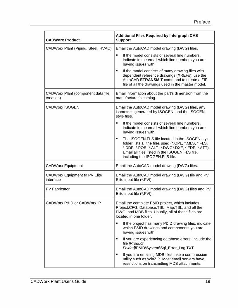
Preface CADWorx Product
Additional Files Required by Intergraph CAS Support
CADWorx Plant (Piping, Steel, HVAC) Email the AutoCAD model drawing (DWG) files.
If the model consists of several line numbers, indicate in the email which line numbers you are having issues with.
If the model consists of many drawing files with dependent reference drawings (XREFs), use the AutoCAD ETRANSMIT command to create a ZIP file of all the drawings used in the master model.
CADWorx Plant (component data file creation)
Email information about the part's dimension from the manufacturer's catalog.
CADWorx ISOGEN Email the AutoCAD model drawing (DWG) files, any isometrics generated by ISOGEN, and the ISOGEN style files.
If the model consists of several line numbers, indicate in the email which line numbers you are having issues with.
The ISOGEN.FLS file located in the ISOGEN style folder lists all the files used (*.OPL, *.MLS, *.FLS, *.DDF, *.POS, *.ALT, *.DWG*.DXF, *.FDF, *.ATT). Email all files listed in the ISOGEN.FLS file, including the ISOGEN.FLS file.
CADWorx Equipment Email the AutoCAD model drawing (DWG) files.
CADWorx Equipment to PV Elite interface
Email the AutoCAD model drawing (DWG) file and PV Elite input file (*.PVI).
PV Fabricator Email the AutoCAD model drawing (DWG) files and PV Elite input file (*.PVI).
CADWorx P&ID or CADWorx IP Email the complete P&ID project, which includes Project.CFG, Database.TBL, Map.TBL, and all the DWG, and MDB files. Usually, all of these files are located in one folder.
If the project has many P&ID drawing files, indicate which P&ID drawings and components you are having issues with.
If you are experiencing database errors, include the file [Product Folder]\P&ID\System\Sql_Error_Log.TXT.
If you are emailing MDB files, use a compression utility such as WinZIP. Most email servers have restrictions on transmitting MDB attachments.
CADWorx Plant User's Guide 19

Preface CADWorx Steel Email the AutoCAD model drawing (DWG) files.
If the model consists of many components, indicate in the model which components or location you are having issues with.
CADWorx Datasheets Email the datasheets MDB file and any datasheet file generated (XLS).
If emailing MDB / XLS files, use a compression utility such as WinZIP. Most email servers have restrictions on transmitting MDB / XLS attachments.
CADWorx Plant to CAESAR II interface
Email the AutoCAD model drawing (DWG) file and CAESAR II input file (*._A, *.C2).
Run the CADWorx GETALLSPECDATAFILES command to copy all specifications and data files used in the model into sub-folders under where the model drawing file is located.
Zip the contents of these folders and email the ZIP file to Intergraph CAS Support.
If the model consists of several line numbers, indicate in the email which line numbers you are having issues with.
CADWorx Design Review or CADWorx Design Create
Email the AutoCAD model drawing (DWG) files.
If the model consists of several line numbers, indicate in the email which line numbers you are having issues with.
If the model consists of many drawing files with dependent reference drawings (XREFs), use the AutoCAD ETRANSMIT command to create a ZIP file of all drawings used in the master model.
CADWorx Design Viewer Email the AutoCAD model drawing (DWG) files and the *.CDR file.
If you are attaching large or multiple files to your eCustomer log, use a compression utility
such as WinZIP.
If you cannot attach your drawing files, then try to duplicate the issue in a new drawing with as few components as possible. If the issue can be duplicated in a new drawing, attach the duplicate drawing to Intergraph CAS.
For hardware lock issues, first verify that you have an Intergraph CAS hardware lock. CADWorx Plant Professional, CADWorx P&ID, CADWorx P&ID Professional, CADWorx Plant Ductile Iron, and CADWorx Plant Sanitary use the Intergraph CAS hardware lock for licensing. CADWorx Steel, CADWorx Steel Professional Plus do not use the Intergraph CAS hardware lock for licensing. For more information about hardware locks, see CADWorx Hardware Lock Identification in the CADWorx Installation Guide.
20 CADWorx Plant User's Guide
Preface
What's New in Plant Version 2015 (15.0)
This user's guide has the following changes for this release.
Items added and updated with CADWorx Plant Professional 2015
Software Enhancements You can now turn updates on or off for Layer/color in the Apply Change Data Rule. For
more information, see Apply Change Data Rule Dialog Box (on page 54).
You can now create threaded needle valves with male threaded by female threaded ends.
You can now route mitered elbows using the Miter Elbow Buttweld elbow type or from the component List. Component List is explained in Auto Route (on page 221). For more information, see Auto Route (on page 221) and Continue Routing (on page 223).
You can now insert a cross and a tee with reducers. The software bases the size of the component on the connected branch of the other component. For more information, see New and Edit Component Pane in the CADWorx Spec Editor Users Guide.
You can now create skewed piping. You must set a maximum angle for the skew with the Apply Skew Pipe Maximum Angle rule if you do not want the default 15º degree value. For more information, see Auto Route (on page 221), Route skewed pipe (on page 224), and Apply Skew Pipe Maximum Angle (on page 55).
You can now use the ISOGEN Configuration Panel in I-Configure.
When setting up a user defined material list in the ISOGEN Configuration panel you can now use the attribute name -80 to display the short description column with text wrapping when running ISOGEN Out . For more information, see Setup short description column for material list with text wrapping (on page 121).
You can now generate isometric drawings for curved piping by setting the Threshold in ISOGEN Configuration to greater than 0. Generate these drawings by creating an adjustable bend, setting the ISOGEN Data dialog box SKEY to PB** (** designates a valid ISOGEN end type), and then running ISOGEN Out or ISOGEN Batch . For more information, see ISOGEN Out (on page 118), ISOGEN Batch (on page 123), Adjustable Bend (on page 384), and Enable curved piping in Plant isometrics (on page 122).
You can now turn visibility of TAPs on or off in the system layer with the SYSVIS command. For more information, see System Visibility (on page 210).
The software now allows descriptions of end types for swages. For more information on the new end types included, see PipeDescriptionCat (on page 41).
You have more options when you use the CHANGESIZE command to change the size of a tee. For more information, see Change Size (on page 61), Change tee sizes automatically (on page 65), and Change tee sizes manually (on page 66).
You can now type a value in Default Value of the Custom Data tab in the CADWorx Spec View palette to override the custom data from the Specification Editor. If you set up custom data with the List option, you can select an item from the Default Value to apply it as an override. For more information, see Spec View Palette (on page 88) and Custom Data Tab (CADWorx Spec View Palette (on page 91).
CADWorx Plant User's Guide 21
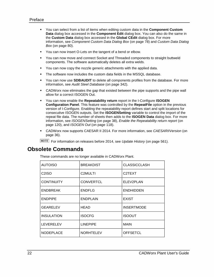
Preface You can select from a list of items when editing custom data in the Component Custom
Data dialog box accessed in the Component Edit dialog box. You can also do the same in the Custom Data dialog box accessed in the Global CEdit dialog box. For more information, see Component Custom Data Dialog Box (on page 78) and Custom Data Dialog Box (on page 80).
You can now insert O-Lets on the tangent of a bend or elbow.
You can now move and connect Socket and Threaded components to straight buttweld components. The software automatically deletes all extra welds.
You can now copy the nozzle generic attachments with the applied data.
The software now includes the custom data fields in the MSSQL database.
You can now use SDBAUDIT to delete all components profiles from the database. For more information, see Audit Steel Database (on page 342).
CADWorx now eliminates the gap that existed between the pipe supports and the pipe wall allow for a correct ISOGEN Out.
You can now enable the Repeatability return report in the I-Configure ISOGEN Configuration Panel. This feature was controlled by the RepeatFile option in the previous version of I-Configure. Enabling the repeatability report defines start and split locations for consecutive ISOGEN outputs. Set the ISOGENSetting variable to control the import of the repeat file data. The number of sheets then adds to the ISOGEN Data dialog box. For more information, see ISOGENSetting (on page 38), Enable the Repeatability return report (on page 120), and ISOGEN Out (on page 118).
CADWorx now supports CAESAR II 2014. For more information, see CAESARIIVersion (on page 36).
For information on releases before 2014, see Update History (on page 561).
Obsolete Commands These commands are no longer available in CADWorx Plant.
AUTOISO BREAKDIST CLASSICCLASH
C2ISO C2MULTI C2TEXT
CONTINUITY CONVERTCL ELEV2PLAN
ENDBREAK ENDFLG ENDHIDDEN
ENDPIPE ENDPLAIN EXIST
GEARELEV HEAD INSERTMODE
INSULATION ISOCFG ISOOUT
LEVERELEV LINEPIPE MAIN
NODEPLACE NORHTELEV OFFSETCL
22 CADWorx Plant User's Guide

Preface OPERPLAN OSYELEV PIPEIN
PIPEOUT PUMP RECT
RED ROLLEDFLG ROLLEDPLAIN
SETANGLE SOUTHELEV SPEC
SPECCHG TANK VESSEL
VESSELOD WESTELEV 3DFOLLOW
Online Help To access the CADWorx Plant Help, type MANUAL on the command line, and then press ENTER. This help file includes the Plant book, the Spec Editor book, and the CADWorx Plant Tutorial.
CADWorx Plant User's Guide 23

Preface
24 CADWorx Plant User's Guide

S E C T I O N 1
Before you begin using CADWorx Plant, you need to set options and some basic configuration tasks.
Your project administrator needs to review and update the catalog (.cat) and project (.prj) file in the Spec Editor before modeling begins.
In This Section Startup Defaults ............................................................................. 25 Support Directory ........................................................................... 25 MVSetup ........................................................................................ 25
Startup Defaults When starting CADWorx Plant for the first time, you are prompted for the system of measurement to use in the drawing. This dialog box only displays the first time you start CADWorx. After that, the configuration file name and location is stored in the registry. The following options are available:
Imperial Measurements - Imperial Pipe Sizes - Restores the [Product Folder]\Plant\System\Imperial.cfg file.
Metric Measurements - Imperial Pipe Sizes - Restores the [Product Folder]\Plant\System\Metric.cfg file.
Metric Measurements - Metric Pipe Sizes - Restores the [Product Folder]\Plant\System\Metric.cfg file.
Support Directory Drawings in the [Product Folder]\Plant\Support folder should not be opened with CADWorx Plant. If a drawing is started in this folder, an error displays indicating that the software should not be run from this location. This stops CADWorx from initializing or preparing the support drawings. Directly open AutoCAD to modify these drawings.
To create a base profile, see Creating a Base Profile (on page 558).
MVSetup Plant menu: Utility > MVSetup
Plant uses the MVSETUP.LSP file supplied by AutoCAD. The software also supplies a simplified version of the MVSETUP.DFS file in the [Product Folder]\Plant\Support folder. If this file is deleted, the software recreates it.
The MVSETUP.DFS file can be modified to include additional title blocks. Plant uses these title blocks with the Setup (on page 28) function. The MVSetup routine has options that allow you to add and delete title blocks. Plant supplies its own title blocks for your convenience. Plant title blocks have attributes attached for ease of labeling.
Setup
CADWorx Plant User's Guide 25

Setup
26 CADWorx Plant User's Guide
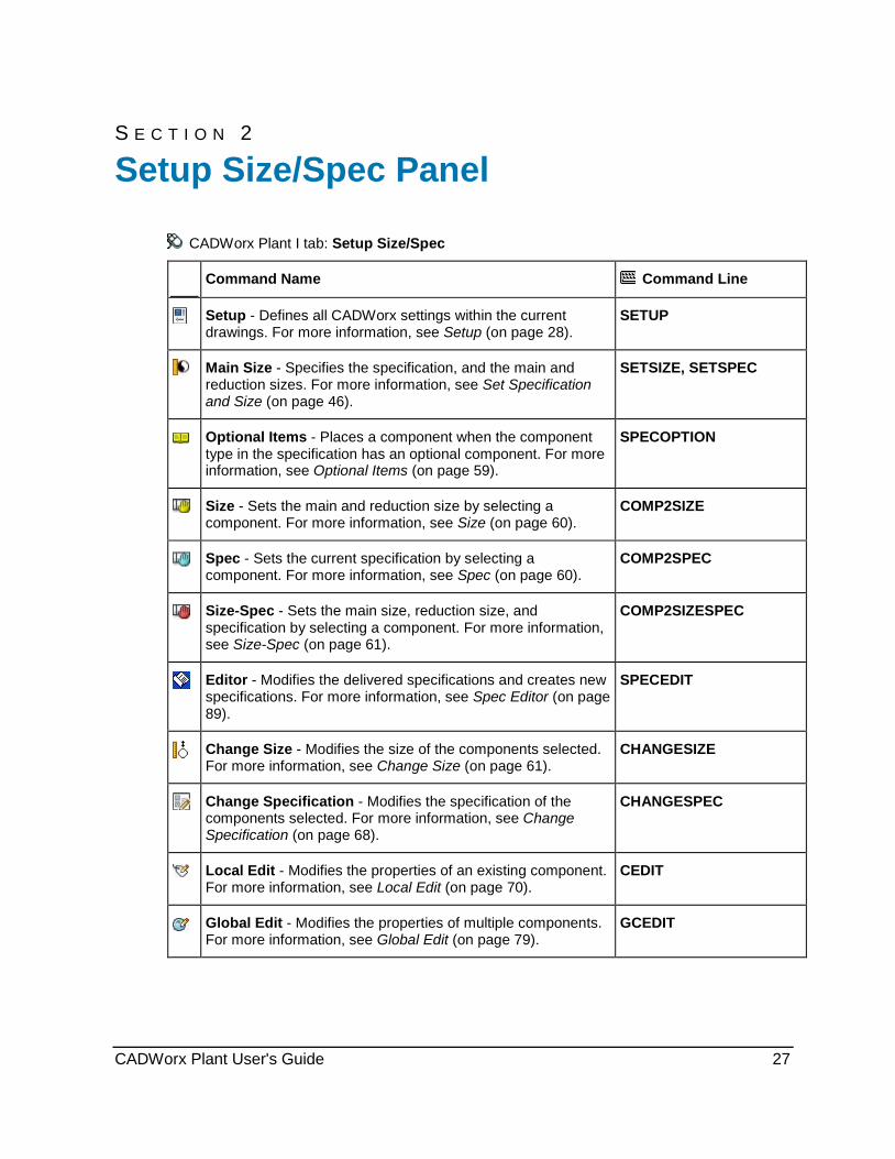
S E C T I O N 2
CADWorx Plant I tab: Setup Size/Spec
Command Name Command Line
Setup - Defines all CADWorx settings within the current drawings. For more information, see Setup (on page 28).
SETUP
Main Size - Specifies the specification, and the main and reduction sizes. For more information, see Set Specification and Size (on page 46).
SETSIZE, SETSPEC
Optional Items - Places a component when the component type in the specification has an optional component. For more information, see Optional Items (on page 59).
SPECOPTION
Size - Sets the main and reduction size by selecting a component. For more information, see Size (on page 60).
COMP2SIZE
Spec - Sets the current specification by selecting a component. For more information, see Spec (on page 60).
COMP2SPEC
Size-Spec - Sets the main size, reduction size, and specification by selecting a component. For more information, see Size-Spec (on page 61).
COMP2SIZESPEC
Editor - Modifies the delivered specifications and creates new specifications. For more information, see Spec Editor (on page 89).
SPECEDIT
Change Size - Modifies the size of the components selected. For more information, see Change Size (on page 61).
CHANGESIZE
Change Specification - Modifies the specification of the components selected. For more information, see Change Specification (on page 68).
CHANGESPEC
Local Edit - Modifies the properties of an existing component. For more information, see Local Edit (on page 70).
CEDIT
Global Edit - Modifies the properties of multiple components. For more information, see Global Edit (on page 79).
GCEDIT
Setup Size/Spec Panel
CADWorx Plant User's Guide 27

Setup Size/Spec Panel
3D Solids - Converts selected components to 3D solid mode. For more information, see Mode Convert (on page 81) and 3D Solids (on page 82).
CONVERTSOLID
Convert Isometric - Converts selected components to isometric mode. For more information, see Mode Convert (on page 81) and Convert Isometric (on page 82).
CONVERTISO
2D Double Line - Converts selected components to 2D double line mode. For more information, see Mode Convert (on page 81) and 2D Double Line (on page 82).
CONVERTDOUBLE
2D Single Line - Converts selected components to 2D single line mode. For more information, see Mode Convert (on page 81) and 2D Single Line (on page 82).
CONVERTSINGLE
Socket Weld - Sets the socket welded fitting mode for hub-based components. For more information, see Socket Weld (on page 84).
—
Threaded - Sets the threaded fitting mode for hub-based components. For more information, see Threaded (on page 84).
—
Settings - Displays the current drawing settings. For more information, see Settings (on page 85).
CURRENT
Xref Edit - Views sizes or information within the component XREF. For more information, see Xref Edit (on page 85).
XCEDIT
Spec Change Toggle - Turns the TAG value update on or off. SPECCHGTOGGLE
Setup CADWorx Plant I tab: Setup Size/Spec > Setup
Setting toolbar: Setup
Plant menu: Setup
Command line: SETUP
Defines all CADWorx settings within the current drawing. This command displays the CADWorx Plant Setup dialog box.
28 CADWorx Plant User's Guide
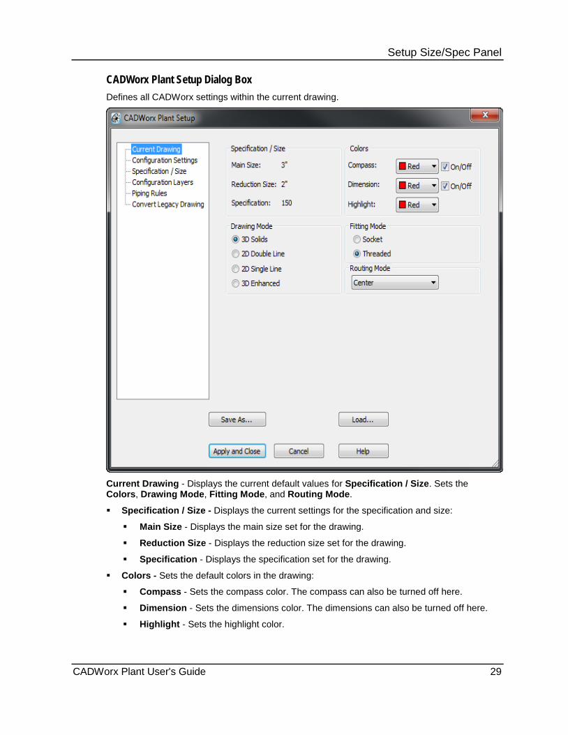
Setup Size/Spec Panel CADWorx Plant Setup Dialog Box Defines all CADWorx settings within the current drawing.
Current Drawing - Displays the current default values for Specification / Size. Sets the Colors, Drawing Mode, Fitting Mode, and Routing Mode.
Specification / Size - Displays the current settings for the specification and size:
Main Size - Displays the main size set for the drawing.
Reduction Size - Displays the reduction size set for the drawing.
Specification - Displays the specification set for the drawing.
Colors - Sets the default colors in the drawing:
Compass - Sets the compass color. The compass can also be turned off here.
Dimension - Sets the dimensions color. The dimensions can also be turned off here.
Highlight - Sets the highlight color.
CADWorx Plant User's Guide 29
Setup Size/Spec Panel Drawing Mode - Sets the default drawing mode:
3D Solids - Draws components in 3D mode.
2D Double Line - Draws components in 2D with double lines mode.
2D Single Line - Draws components in 2D with a single line mode.
3D Enhanced - Draws components in 3D enhanced mode. Bolts, gaskets, and welds display in their real world appearance in this mode.
You can convert the drawing to another mode. For more information, see Mode Convert (on page 81).
Fitting Mode - Specifies the fitting mode for hub-based components. Select one of the following: Socket - Dimensions and engagement properties are based on the socket welded
section of the specification. Threaded - Dimensions and engagement properties are based on the threaded section
of the specification.
Routing Mode - Specifies the mode for routing pipe in the drawing.
Center - Specifies the component is routed using the center line to draw the component.
BOP - Specifies the component is routed using the bottom of pipe to draw the component.
TOP - Specifies the component is routed using the top of pipe to draw the component.
Left - Specifies the component is routed using the left of the pipe to draw the component.
Right - Specifies the component is routed using the right of the pipe to draw the component.
Configuration Settings - Sets the values for the configuration. For more information, see Startup Variables (on page 31).
Specification / Size - Sets the specification and sizes of the drawing. Specification must be set before sizes can be set. For more information, see Set Specification and Size (on page 46).
Configuration Layers - Specifies drawing layers and the default names, line types, and colors of the layers. Default layers are provided. You can add and delete layers. For more information, see Configuration Layers (on page 47).
Piping Rules - Sets the piping rules in the drawing. For more information, see Piping Rules (on page 49).
Convert Legacy Drawing - Enables you to convert a legacy drawing to 2013 components. For more information, see Convert Legacy Drawing (on page 55).
Save As - Saves the current configuration.
Load - Loads a saved configuration.
Apply and Close - Accepts the settings and closes the dialog box. Settings are immediately applied to the current drawing.
Cancel - Cancels the operation.
Help - Displays the CADWorx Plant Users Guide help file.
30 CADWorx Plant User's Guide

Setup Size/Spec Panel
Configuration Settings Specifies values for the selected configuration setting.
The default drawing template, Imperial.dwt (Metric.dwt for metric) is also stored in the
registry. Each time the software is started, the default template is used.
The drawing parameters are setup during installation for imperial or metric in the setup profile. If you want to change the configuration setting to the drawing parameters, use the SystemMeasure (on page 45) variable to change the drawing settings.
Configuration Settings - Displays variables to change. Change variable values in the text box list. For more information, see Startup Variables (on page 31).
If the configuration settings permission is set to read-only, only the Cancel button is available.
Startup Variables Provides default drawing and component values. You can modify the variables in the configuration setting as needed. For more information, see Configuration Settings (on page 31). The most recent configuration settings are stored in the registry and are used the next time you start Plant.
Topics Drawing Prototype ......................................................................... 32 AlphaSizeControl ........................................................................... 32 AuditDataOnStartup....................................................................... 33 AutoDimensionBox ........................................................................ 33 BomBoltControl .............................................................................. 34 BomScheduleDirection .................................................................. 34 BomScheduleSpacing ................................................................... 34 BomTagGridFactor ........................................................................ 34 BomTagOptimize ........................................................................... 35 BomTagRadiusFactor .................................................................... 35 BomTagSpacingFactor .................................................................. 35 BoltRoundControl .......................................................................... 35 CADWorxMaterial .......................................................................... 35 CAESARIIMaterial ......................................................................... 36 CAESARIIMemory ......................................................................... 36 CAESARIITolerance ...................................................................... 36 CAESARIIVersion .......................................................................... 36 DataBaseCodesISOGEN .............................................................. 36 DimensionsExcludedSlope ............................................................ 37 DimensionsExistingISOGEN ......................................................... 37 ElbowCenterLine ........................................................................... 37 FittingWidth .................................................................................... 37 HVACLibraryDirectory ................................................................... 37 ISOGENDefaultStyle ..................................................................... 38 ISOGENSetting .............................................................................. 38 ISOGENContinuationGraphicsCount ............................................ 38 LanguageFile ................................................................................. 38 LayerByLineNumber ...................................................................... 39
CADWorx Plant User's Guide 31

Setup Size/Spec Panel LineNumberSystem ....................................................................... 41 LineViewIsolationSettingsFile ........................................................ 41 PipeDescriptionCat ........................................................................ 41 PipeSupportSetting ........................................................................ 42 SaveLastProfileUsed ..................................................................... 42 SingleLineWidth ............................................................................. 42 SpecificationDirectory .................................................................... 42 SpecificationDefaultProject ............................................................ 43 SpecSizeOverride .......................................................................... 43 SteelCopeBoltDistance .................................................................. 43 SteelCopeWeldDistance ................................................................ 43 SteelLibraryDirectory ..................................................................... 43 SteelNeutralAxis ............................................................................ 43 SteelPartNumberFile ..................................................................... 44 SteelRoundControl ........................................................................ 44 SteelRoundUnit .............................................................................. 44 SteelToolTipSetting ....................................................................... 44 SyncOnStartUp .............................................................................. 44 SystemMeasure ............................................................................. 45 TemplateDatabaseFile................................................................... 45 ToolTipSetting ................................................................................ 45 TopWorksSetting ........................................................................... 45 UseObjectsFromXrefs ................................................................... 46 WeldDotSize .................................................................................. 46 WeldGapToDB ............................................................................... 46 Drawing Prototype Default value: English/Inch Allowed values: English/Inch, Metric/Inch, and Metric/Metric Enables you to select a drawing environment type: English/Inch - Uses the Imperial dimensions with Imperial pipe sizes. Metric/Inch - Uses the Metric dimensions with Imperial pipe sizes. Metric/Metric - Uses the Metric dimensions with Metric pipe sizes. AlphaSizeControl Default value: 0 Allowed values: 0, 1, 2, 3, 4, 5, 6, 7, 8, 9, or 10
Controls the number of decimal places used in Alpha Size. Setting this variable to zero places no decimals in Alpha Size. Setting the variable to a value from 1 to 9 places 1 to 9 decimal places in Alpha Size. Setting this variable to 10 suppresses trailing zeros in Alpha Size.
Example with a value of 0: For Imperial pipe size: 4 1/2" would be 4 1/2" or 6" would be 6" For Metric pipe size: 50 would be 50 or 60.3 would be 60 Example with a value of 3: For Imperial pipe size: 4 1/2" would be 4.500" or 6" would be 6.000" For Metric pipe size: 50 would be 50.000 or 60.3 would be 60.300 Example with a value of 10: For Imperial pipe size: 4 1/2" would be 4.5" or 6" would be 6" For Metric pipe size: 50 would be 50 or 60.3 would be 60.3
If you want decimals to display in Alpha Size in Imperial or Metric, the recommended setting is 10.
32 CADWorx Plant User's Guide
Setup Size/Spec Panel AuditDataOnStartup Default value: 0 Allowed values: 0, 1
Controls when CADWorx checks components for removed XDATA when opening a drawing.
0 - Checking for removed XDATA is turned off.
1 - Checking for removed XDATA is turned on.
See Also Show Removed XDATA (on page 33)
Restore XDATA (on page 33)
Show Removed XDATA
Command line: CWSHOWNOXD
Highlights components where XDATA has been removed.
1. Type CWSHOWNOXD on the command line, and then press ENTER.
2. Type S on the command line or E to select the entire drawing, and then press ENTER.
3. Select the component that you want to change, and then press ENTER.
Step 3 does not apply if you selected the Entire Drawing option in step 2.
The components with XDATA removed highlight in the drawing.
Restore XDATA
Command line: CWADDXD
Restores removed XDATA from a selected specification to a CADWorx component.
1. Type CWADDXD on the command line, and then press ENTER.
2. Select the component that you want to change, and then press ENTER.
3. Type S on the command line or E to select the entire drawing, and then press ENTER.
4. Select the component that you want to change, and then press ENTER.
Step 3 does not apply if you selected the Entire Drawing option in step 2.
The XDATA is added to the component(s).
To restore the xdata of a component, you must use the original specification from that component.
AutoDimensionBox Default value: No Allowed values: No, Yes
Controls boxes around rolling offset automatic dimensions when using Automatic . When set to Yes, a box is drawn for the rolling offset. For more information, see Automatic (on page 230).
CADWorx Plant User's Guide 33
Setup Size/Spec Panel BomBoltControl Default value: 0 Allowed values: 0, 1, 2, or 3
Specifies bolt placement in the Plant ISOGEN bill of material schedules.
0 - Places the quantity for a set in the pre-CADWorx 2002 format, such as: QUANTITY = 4, ALPHA_SIZE = 3/4", LONG_DESC = (8) Studs with nuts
1 - Places the quantity for total bolts, and strips the set number from the long description, such as: QUANTITY = 32, ALPHA_SIZE = 3/4", LONG_DESC = Studs with nuts
2 - Places the quantity for a set, the alpha size based on the flange size, and appends the bolt diameter to the long description, such as: QUANTITY = 4, ALPHA_SIZE = 12", LONG_DESC = (8) 3/4" Studs with nuts.
3 - Places the quantity for total bolts, strips the set number from the long description, places the alpha size based on the flange size, and appends the bolt diameter to the long description, such as: QUANTITY = 32, ALPHA_SIZE = 12", LONG_DESC = 3/4" Studs with nuts
When this option is set to 1 or 3, the long description of the bolt must contain the number of bolts in the set enclosed by parenthesis. The software uses the value in parenthesis as the new quantity. The number is then automatically removed from the long description when displayed in the material list.
BomScheduleDirection Default value: Down Allowed values: Down or Up Specifies the direction of the bill of materials schedule. Up - Places the bill of materials schedule in the upward direction, with the column headings
at the bottom. Down - Places the bill of materials schedule in the downward direction, with the column
headings at the top. BomScheduleSpacing Default value: 0.25 Allowed values: Positive real
Controls the spacing on the bill of material schedule. BomTagGridFactor Default value: 1.0 Allowed values: Positive real
Controls the bill of material tag grid density on the drawing.
When BomTagOptimize (on page 35) is set to 2, set this variable to 0.5, 1.0, 2.0, or 3.0.
34 CADWorx Plant User's Guide
Setup Size/Spec Panel BomTagOptimize Default value: 2 Allowed values: 0, 1, or 2
Specifies the tagging algorithm used for the bill of material.
0 - The tagging algorithm is off.
1 - The algorithm is on, but does not stack any tags.
2 - The algorithm is on. Flange, bolt, and gasket tags are stacked.
BomTagRadiusFactor Default value: 1.25 Allowed values: Positive real
Controls the radius of tag bubbles. Bubbles are sized using this factor multiplied by the AutoCAD setvar TEXTSIZE.
BomTagSpacingFactor Default value: 1.25 Allowed values: Positive real
Controls how far bill of materials bubbles are spaced from the model or components within the drawing.
BoltRoundControl Default value: 0 Allowed values: 0, 1, 2, or 3
Specifies the rounding for bolt length calculations.
0 - No rounding is performed.
1 - Rounds the value up to the nearest multiple of the value specified in Catalog.
2 - Rounds the value down to the nearest multiple of the value specified in Catalog.
3 - Rounds the value up or down to the nearest multiple of the value specified in Catalog.
CADWorxMaterial Default value: No Allowed values: No or Yes
Controls CADWorx material generation when using System In . For more information, see System In (on page 206).
No - The software bases component descriptions in CADWorx on the material types in CAESAR II. The CADWorx component name is combined with the CAESAR II material type.
Yes - The software bases component descriptions in CADWorx on the specifications. Material types from CAESAR II are ignored.
The component name is defined in the [Product Folder]\Plant\System\Prgm.tbl file.
CADWorx Plant User's Guide 35
Setup Size/Spec Panel CAESARIIMaterial Default value: 0 Allowed values: 0, 1, or 2
Controls CAESAR II material generation when using System Out . For more information, see System Out (on page 198).
0 - Provides extended material database material types in CAESAR II based on the pipe material defined in Spec Editor . This does not apply if the component was originally created in CAESAR II.
1 - Provides basic material types in CAESAR II (1-17) corresponding to the component material long description in the specification.
2 - Provides extended material database material types in CAESAR II based on the actual component material long description in the specification.
When using CAESAR II version 3.23, only option 1 can be used.
CAESARIIMemory Default value: 12.0 Allowed values: Positive real
Specifies the amount of computer RAM used when importing a large CAESAR II input model. This variable is not required, but is helpful if the import is failing. The value is multiplied by megabytes.
CAESARIITolerance Default value: 0.001 Allowed values: Positive real
Specifies the tolerance for items that are not transferring correctly to CAESAR II. For example, hangers placed on a skewed line sometimes fail and require a larger tolerance factor.
CAESARIIVersion Default value: 2014 Allowed values: 2011, 2013, or 2014
Specifies the format of the CAESAR II (.c2) input file created by CADWorx. The value should match the version of CAESAR II that you are using.
DataBaseCodesISOGEN Default value: No Allowed values: No or Yes
Specifies how CADWorx ISOGEN uses the DataBaseCodes system.
No - The DataBaseCodes system is not used. CADWorx Plant creates generic item code combinations for each run of ISOGEN, starting at 1 for each run. Components with identical long annotation and specification file names are given the same item-code combination.
Yes - ISOGEN uses the DataBaseCodes system.
If this option is set to Yes and a valid DataBaseCodes system is not established, bill of material generation within ISOGEN is not correct.
36 CADWorx Plant User's Guide

Setup Size/Spec Panel DimensionsExcludedSlope Default value: 10.0 Allowed values: Positive real
Specifies the minimum percentage slope (rise/run) for automatic dimensioning of the vertical leg of sloped pipe when using Automatic . If the pipe slope is under the specified value, then the vertical leg dimension and the associated hatched graphics for the rise are not placed. The horizontal dimension is still placed.
For more information, see Automatic (on page 230).
DimensionsExistingISOGEN Default value: 0 Allowed values: 0, 1, or 2
Controls ISOGEN isometric representation of existing components.
0 - Existing components are exported with dotted lines and are dimensioned.
1 - Existing components are exported with dotted lines and are not dimensioned.
2 - Existing components are exported with solid lines and are dimensioned.
Individual ISOGEN dimension settings override this setting. For more information, see ISOGEN Data Dialog Box (on page 73).
ElbowCenterLine Default value: 0 Allowed values: 0 (off) or 1 (on)
Controls square elbow centerlines on elbow-type components. When set to 1, an additional square centerline is drawn without drawing square elbow graphics. These lines appear in 2D double line and Isometric modes only.
You can also control this variable by setting the Elbow Centerline in CADWorx Plant menu: Utilities > Drawing Control > Elbow Centerline.
FittingWidth Default value: 1.0 Allowed values: Positive real
Specifies the appearance of all flanged, socket welded, and threaded fittings. When set to 1.0, the software draws fitting hubs or flange ODs at 100% of the width specified in their data file. This variable is useful at a value of 0.7 when drawing socket weld and threaded type hub fittings where the hubs overlap.
HVACLibraryDirectory Default value: [Product Folder]\Plant\HVAC Allowed values: Valid directory name
Defines the location of the data files folder used for HVAC components.
CADWorx Plant User's Guide 37
Setup Size/Spec Panel ISOGENDefaultStyle Default value: <none> Allowed values: Full path to an Isogen.fls file
Specifies the ISOGEN style used by ISOGEN Out and ISOGEN Batch .
For more information, see ISOGEN Out (on page 118) and ISOGEN Batch (on page 123).
When this variable is defined, ISOGEN Out does not display the Select ISOGEN Style dialog box.
ISOGENSetting Default value: 0 Allowed values: 0, 1, 2, or 3
Controls import of ISOGEN repeat file data when running ISOGEN Out (on page 118) or ISOGEN Batch (on page 123).
ISOGEN Repeat File has to be configured in the ISOGEN Project for the repeat file import to be active.
0 - Turns off all settings.
1 - Imports Mark/Sheet data from the repeat file.
2 - Imports Spool data from the repeat file.
3 - Imports Mark/Sheet/Spool data from the repeat file.
ISOGENContinuationGraphicsCount Default value: 0 Allowed values: 0, 1, 2, or 3
Displays continuation graphics based on the following selections:
0 - Display no continuation graphics when running ISOGEN.
1 - Display one continuation graphic when running ISOGEN.
2 - Display two continuation graphics when running ISOGEN.
3 - Displays three continuation graphics when running ISOGEN.
LanguageFile Default value: English.dic Allowed values: A valid and properly formatted language file
Specifies the language of all Plant dialog boxes and prompts. The specified file must be present in the [Product Folder]\Plant\Support folder for proper operation of Plant.
You must set the LanguageFile to the regional language when using a language-specific specification. For example, if you have Chinese characters in your specification, set the LanguageFile to Chinese_Simplified.dic. If you do not, System Out (on page 198) and System In (on page 206) do not function correctly.
38 CADWorx Plant User's Guide
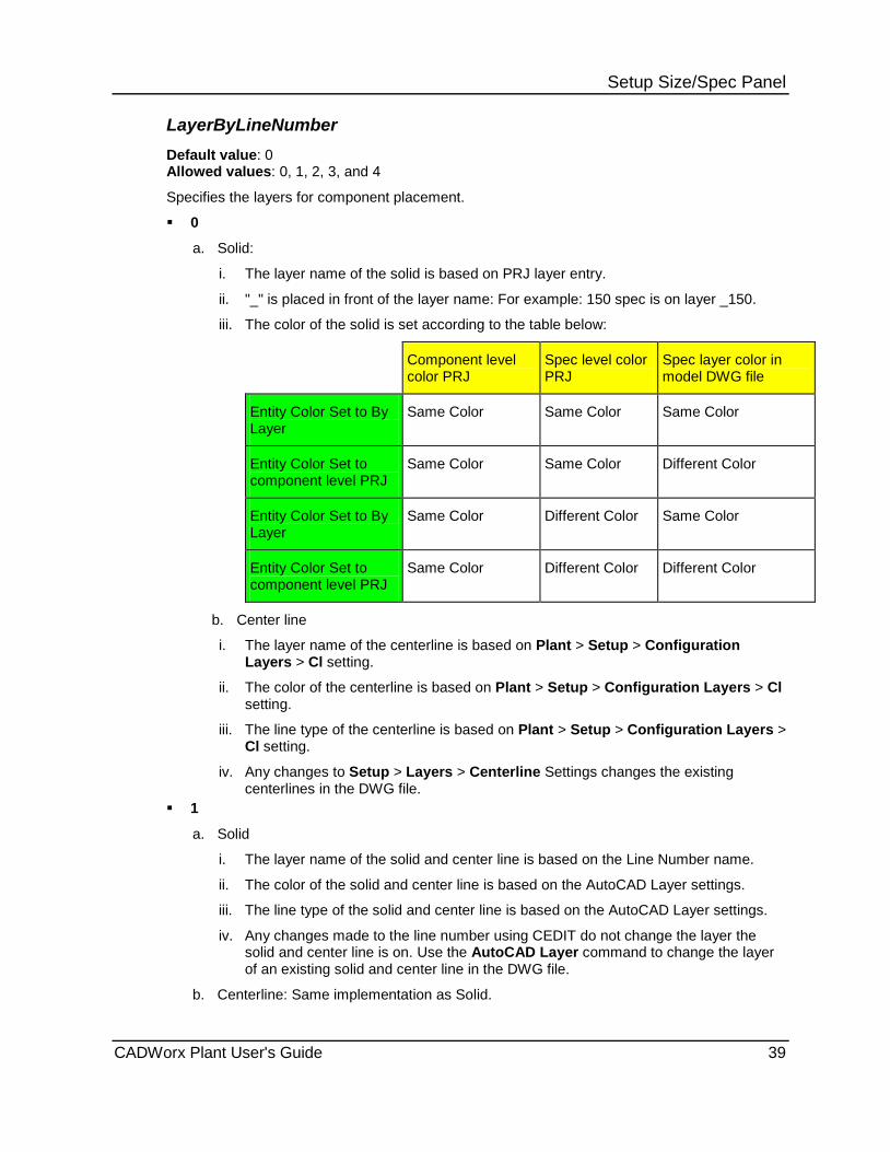
Setup Size/Spec Panel LayerByLineNumber Default value: 0 Allowed values: 0, 1, 2, 3, and 4
Specifies the layers for component placement.
0
a. Solid:
i. The layer name of the solid is based on PRJ layer entry.
ii. "_" is placed in front of the layer name: For example: 150 spec is on layer _150.
iii. The color of the solid is set according to the table below:
Component level color PRJ
Spec level color PRJ
Spec layer color in model DWG file
Entity Color Set to By Layer
Same Color Same Color Same Color
Entity Color Set to component level PRJ
Same Color Same Color Different Color
Entity Color Set to By Layer
Same Color Different Color Same Color
Entity Color Set to component level PRJ
Same Color Different Color Different Color
b. Center line
i. The layer name of the centerline is based on Plant > Setup > Configuration Layers > Cl setting.
ii. The color of the centerline is based on Plant > Setup > Configuration Layers > Cl setting.
iii. The line type of the centerline is based on Plant > Setup > Configuration Layers > Cl setting.
iv. Any changes to Setup > Layers > Centerline Settings changes the existing centerlines in the DWG file.
1
a. Solid
i. The layer name of the solid and center line is based on the Line Number name.
ii. The color of the solid and center line is based on the AutoCAD Layer settings.
iii. The line type of the solid and center line is based on the AutoCAD Layer settings.
iv. Any changes made to the line number using CEDIT do not change the layer the solid and center line is on. Use the AutoCAD Layer command to change the layer of an existing solid and center line in the DWG file.
b. Centerline: Same implementation as Solid.
CADWorx Plant User's Guide 39

Setup Size/Spec Panel 2
a. Solid:
i. The layer name of the solid is based on the Line Number name. ii. The color of the solid is based on the AutoCAD Layer settings. iii. The line type of the solid is based on the AutoCAD Layer settings. iv. Any changes made to the line number using CEDIT do not change the layer the
solid is on. Use the AutoCAD Layer command to change the layer of an existing solid in the DWG file.
b. Centerline: i. The layer name of the centerline is based on Plant > Setup > Configuration
Layers > Cl setting. ii. The color of the centerline is based on Plant > Setup > Configuration Layers > Cl
setting. iii. The line type of the centerline is based on Plant > Setup > Configuration Layers >
Cl setting. iv. Any changes made to the line number using CEDIT do not change the layer the
solid is on. Use the AutoCAD Layer command to change the layer of an existing centerline in the DWG File.
3
a. Solid
i. The layer name of the solid and center line is based on the Line Number name. ii. The color of the solid and center line has the same implementation for solid color as
LayerByLineNumber = 0 setting shown in the table above. iii. The line type of the solid and center line is based on the AutoCAD Layer settings. iv. Any changes made to the line number using CEDIT do not change the layer the
solid and center line is on. Use the AutoCAD Layer command to change the layer of an existing solid and center line in the DWG file.
b. Centerline: Same implementation as the Solid. 4
a. Solid: i. The layer name for solid is based on the Line Number name. ii. The color of the solid has the same implementation for solid color as
LayerByLineNumber = 0 setting shown in table above. iii. The line type of the solid is based on the AutoCAD Layer settings. iv. Any changes made to the line number using CEDIT do not change the layer the
solid is on. Use the AutoCAD Layer command to change the layer of an existing solid in the DWG file.
b. Centerline: i. The layer name of the centerline is based on Plant > Setup > Configuration
Layers > Cl setting. ii. The color of the centerline is based on Plant > Setup > Configuration Layers > Cl
setting. iii. The line type of the centerline is based on Plant > Setup > Configuration Layers >
Cl setting. iv. Any changes made to the line number using CEDIT do not change the layer the
solid is on. Use the AutoCAD Layer command to change the layer of an existing centerline in the DWG file.
40 CADWorx Plant User's Guide

Setup Size/Spec Panel LineNumberSystem Default value: 1 Allowed values: 0 (off), 1 (on), or 2 (static)
Specifies the line number system.
0 - Line numbers are manually entered.
1 - Size, spec, and count number are used for the line number
2 - Count number is used for the line number.
LineViewIsolationSettingsFile Default value: [Product Folder]\Plant\[user-defined folder] Allowed values: Valid file path (*.lvi)
Provides the location of the Isolation Settings File.
Sets the filter settings default file. When using the Line View Isolation Properties Manager, the Isolation Setting File uses the file associated with the LineViewIsolationSettingsFile variable and opens it as the default file. For more information on the Line View Isolation Properties Manager, see Line View Isolation Properties Manager (on page 93).
PipeDescriptionCat Default value: 0 Allowed values: 0 through 6
Specifies the addition of end types to the long description, DataBaseCodes, and end prep for:
For end prep to show, you must have the end prep schema set in the description formats. For more information, see Description Format Dialog Boxes, and Long, Short, Tag, and Part Number Dialog Boxes in the CADWorx Spec Editor Users Guide.
Small-bore threaded or socket-welded pipe when using Thrd/SW Pipe . For more information, see Thrd/SW Pipe (on page 496).
Nipple components when using Nipple . For more information, see Nipple (on page 497).
Small-bore pipe that is broken by an inserted component when using Router . For more information, see Router (on page 225).
Swage components when using the Swage reducer from CADWorx Spec View palette.
The following end descriptions are provided:
BBE - Bevel Both Ends BOE-TOE - Bevel One End - Threaded One End BOE-POE - Bevel One End - Plain One End PBE - Plain Both Ends POE-TOE - Plain One End, Threaded One End TBE - Threaded Both Ends BLE-TSE - Bevel Large End - Threaded Small End BLE-PSE - Bevel Large End - Plain Small End TLE-BSE - Threaded Large End - Bevel Small End TLE-PSE - Threaded Large End - Plain Small End
CADWorx Plant User's Guide 41

Setup Size/Spec Panel 0 - End types are not added to any components.
1 - End types are added to long descriptions, DataBaseCodes, and part number for pipes, nipples, and swages.
2 - End types are added to long descriptions for pipes, nipples, and swages.
3 - End types are added to long descriptions and DataBaseCodes for pipe only.
4 - End types are added to long descriptions for pipe only.
5 - End types are added to long descriptions and DataBaseCodes for nipples and swages.
6 - End types are added to long descriptions for nipples and swages.
This setting works in conjunction with Apply Pipe End Prep Rule. Both must be set to display, (Automatic for Apply Pipe End Prep Rule and 1 through 6 for PipeDescriptionCat) or the PipeDescriptionCat does not display on the Long annotation of the Component Edit dialog box. For more information, see Apply Pipe End Prep Rule (on page 52).
PipeSupportSetting Default value: 1 Allowed values: 0, 1, or 2
Specifies the layer for pipe support component placement.
0 - The pipe support is placed on a layer set from the CADWorx layer settings.
1 - The pipe support is placed on the same layer as the connecting pipe or elbow component.
2 - The pipe support is placed on a new layer. The layer name is derived by appending the component layer name and the pipe support layer name. For example, if the pipe solid is on layer _150, and the pipe support layer name is SUPT, then the pipe support is on new layer _150SUPT.
SaveLastProfileUsed Default value: No Allowed values: No or Yes
Specifies whether CADWorx saves the last profile used on exit.
When a drawing file is double-clicked in Windows Explorer, or if AutoCAD is started using an icon without specifying any profile, AutoCAD always loads the last profile used. No - Prevents CADWorx from saving the last profile used. Yes - Allows CADWorx to save the last profile used. SingleLineWidth Default value: 0.02 Allowed values: Positive real
Specifies the default width for a single line pipe.
SpecificationDirectory Default value: [Product Folder]\Plant\Spec Allowed values: Valid folder Provides the location of the specifications folder.
This folder can be set as read-only.
42 CADWorx Plant User's Guide

Setup Size/Spec Panel SpecificationDefaultProject Default value: Valid PRJ file Allowed values: Valid PRJ file
Specifies the spec default project file.
Project files store specification information for all components in CADWorx. Setting a project file here enables it to be the default project used for all modeling. This file can be opened using the Specification Editor. When modeling, the information is accessed using this file to create the components. For more information, see Spec Editor (on page 89).
SpecSizeOverride Default value: Yes Allowed values: No or Yes
Controls the ability to override component specification and size. If override is turned off, you are not able to draw out of spec or out of size. Yes - Overrides the specification and size limits. No - Limits drawing to values within specification and size limits. SteelCopeBoltDistance Default value: 0.5 (Imperial) 15 (Metric) Allowed values: Positive real Specifies the distance used when two steel beams are coped using the bolted method of Cope
. For more information, see Steel - Cope (on page 318). SteelCopeWeldDistance Default value: 0.0 Allowed values: Positive real Specifies the distance used when two steel beams are coped using the welded method of Cope
. For more information, see Steel - Cope (on page 318). SteelLibraryDirectory Default value: [Product Folder]\Plant\Steel_I ([Product Folder]\Plant\Steel_M for metric) Allowed values: Valid folder name
Locates the data file used for drawing Steel. The data files can be located anywhere on the computer, local network, or wide area network.
This folder can be set as read-only.
SteelNeutralAxis Default value: 0 Allowed values: 0, 1, 2, or 3
Specifies the location of centerlines for steel channels and angles.
0 - The centerline is drawn at the X--column value specified in the channel or angle data files.
1 - The centerline is drawn at the midpoint of the flange. 2 - The centerline is drawn on the inside of the flange. Use this value if channels and angles
are coped with other members. 3 - The centerline is drawn on the outside of the flange. Use this value if channels and
angles are mitered with other members.
CADWorx Plant User's Guide 43
Setup Size/Spec Panel SteelPartNumberFile Default value: SamplePartNumbers.dat Allowed values: Valid and properly formatted part number file
Specifies the file containing part numbers that can be automatically entered for a steel member component. When a steel member is drawn, the software searches the data file for a matching member type and member name. If found, the software then retrieves the part number and saves it with the member component.
SteelRoundControl Default value: 0 Allowed values: 0, 1, 2, or 3
Specifies the rounding of values read from the steel data files.
0 - No rounding is performed.
1 - Rounds the value up to the nearest multiple of the value specified in SteelRoundUnit (on page 44).
2 - Rounds the value down to the nearest multiple of the value specified in SteelRoundUnit (on page 44).
3 - Rounds the value up or down to the nearest multiple of the value specified in SteelRoundUnit (on page 44).
SteelRoundUnit Default value: 0.125 Allowed values: Positive real
Specifies the rounding multiple of values read from the steel data files. This variable is used with SteelRoundControl (on page 44).
SteelToolTipSetting Default value: 4235 Allowed values: Positive integer
Specifies the data displayed in a tooltip when the mouse hovers over a steel component. Click the ellipsis in the value box next to SteelToolTipSetting to open the Tool Tip Data Selection dialog box. Select the needed data to display, and click OK. The correct integer is then displayed for those settings.
SyncOnStartUp Default value: Turn Off Synchronize Allowed values: Synchronize With Prompt, Synchronize Without Prompt, Synchronize With Changes Review
Controls the synchronize option on opening a drawing with an external database:
Turn Off Synchronize - Turns off the synchronize option when a drawing is loaded into AutoCAD.
Synchronize With Prompt - Asks if the software should synchronize the drawing with the external database.
44 CADWorx Plant User's Guide

Setup Size/Spec Panel Synchronize Without Prompt - Synchronizes the drawing with the external database without prompting.
Synchronize With Changes Review - Enables you to review the changes made to the database and accept or reject the changes as needed.
When you click Synchronize , values Turn Off Synchronize and Synchronize With Prompt provide a prompt. Synchronize Without Prompt synchronizes without any prompts. Synchronize With Changes Review displays the Synchronize Component dialog box where you can decide which information you want to update to your drawing from the database.
SystemMeasure Default value: English/Inch Allowed values: English/Inch, Metric/Inch, and Metric/Metric
Specifies the unit system: English/Inch - Uses the imperial system with nominal inch input. Metric/Inch - Uses the metric system with nominal inch input. Metric/Metric - Uses the metric system with metric input. TemplateDatabaseFile Default value: Pipe.mdb Allowed values: Valid Microsoft Access database file name Specifies the database file that is used with a bill of material.
ToolTipSetting Default value: 8405 Allowed values: Positive integer
Specifies the data displayed in a tooltip when the mouse hovers over a component. Click the ellipsis next to ToolTipSetting in Configuration Settings to open the Tool Tip Data Selection dialog box. Select the needed data to display, and click OK. The correct integer is then displayed for those settings.
TopWorksSetting Default value: 1 Allowed values: 0 through 4
Specifies the layers for top works component placement.
0 - Top works are not added to the valve even if a top works file is set in the specification file.
1 - Top works are added to the valve. The top works solid is combined with the valve solid to create one solid.
2 - Top works are added to the valve. The top works solid is grouped with the valve solid and center line. The top works solid is placed on the same layer as the valve solid.
3 - Top works are added to the valve. The top works solid is grouped with the valve solid and center line. The top works solid is placed on a layer set from the CADWorx layer settings.
4 - Top works are added to the valve. The top works solid is grouped with the valve solid and center line. The top works solid id placed on a layer set from the CADWorx layer settings. The layer name is derived by appending the valve layer name and the top works layer name. For example, when the valve is on layer _150, and the top works layer name is TOP, the top works solid is on layer _150TOP.
CADWorx Plant User's Guide 45
Setup Size/Spec Panel UseObjectsFromXrefs Default value: Yes Allowed values: No or Yes
Allows objects from Xrefs (external references) to be used during the selection process.
No - Objects from Xrefs are not used.
Yes - Objects from Xrefs are used for the current command.
WeldDotSize Default value: 1.0 Allowed values: Positive real
Specifies the default weld dot size on single-line, butt-welded piping components.
WeldGapToDB Default value: Yes Allowed values: No or Yes Sets automatic weld gaps to database on or off. Yes - Weld gaps are shown in the Bill of Material schedule. No - Weld gaps are not shown in the Bill of Material schedule.
Set Specification and Size CADWorx Plant I tab: Setup Size/Spec > Setup > Specification / Size CADWorx Plant I tab: Setup Size/Spec > Main Size Setting toolbar: Main Size Setting toolbar: Specification Command line: SETSIZE, SETSPEC
Displays the Set Specification and Size dialog box in which you specify a drawing specification file, a main size, and a reduction size.
Browse - Enables you to open the project specification needed for your drawing. Reload File - Reloads the project (.prj) selected for any changes made in the Specification Editor. Alternatively, type RELOADPROJECTFILE on the command line, and press ENTER. M - Sets the selected row as the main size. R - Sets the selected row as the reduction size. OK - Accepts the selected main and reduction sizes, and closes the dialog box. Cancel - Cancels the operation.
CADWorx Plant specifications are delivered to the [Product Folder]\Plant\Spec folder. The
projects and catalogs are broken down into folders by their units of measure. CADWorx P&ID also provides specifications delivered to the [Product Folder]\P&ID\Spec folder. If Plant and P&ID are used together, you should select specifications from a single folder. For more information, see SpecificationDirectory (on page 42).
The list of available sizes is controlled by [Product Folder]\Plant\System\SetSize.Tbl (English/inches), SetSizeA.tbl (Metric/inches), and SetSizeM.tbl (Metric/mm).
46 CADWorx Plant User's Guide

Setup Size/Spec Panel Set Specification & Size Dialog Box 1. Click Setup > Specification / Size. Alternatively, click Main Size or type SETSPEC
or SETSIZE, and press ENTER.
The Set Specification & Size dialog box displays.
2. Click Browse.
The Open window displays.
3. Navigate to the proper specification, and click Open.
The Specification list populates.
4. Select a specification from the list. This must be done before sizes can be selected.
The Main / Reduction size populates.
5. Select a main size and a reduction size from the list. They can be selected in any order.
6. Click OK.
The specification and main and reduction sizes are set.
Configuration Layers Specifies drawing layers and the default names, line types, and colors of the layers. Default layers are provided. You can add and delete layers.
The default layers are mandatory for use with Plant and cannot be deleted. See the tables
below.
Layer changes made in this dialog box affect the current drawing session similar to the AutoCAD LAYER command.
The commands in this dialog box are inactive if the configuration settings permission is set to read-only.
Layer Name - Specifies the layer name. The layer name can be anything that is allowed by AutoCAD. Wild card characters and spaces are not allowed. Click Update to change the name.
New - Adds a new layer with a default name. New layers are created when the drawing is initialized with Plant. Access this option by right-clicking in the layer name column.
Delete - Removes the selected layer from the list. You cannot delete default layers. Access this option by right-clicking in the layer name column.
Linetype - Specifies the line type for the selected layer. Select a value in the Select Linetype dialog box.
Line types are defined in the [Product Folder]\Plant\Support\Cfm.lin and [AutoCAD Product Folder]\UserDataCache\Support\acad.lin files.
Color - Displays the Select Color dialog box for selecting the color of the layer.
CADWorx Plant User's Guide 47
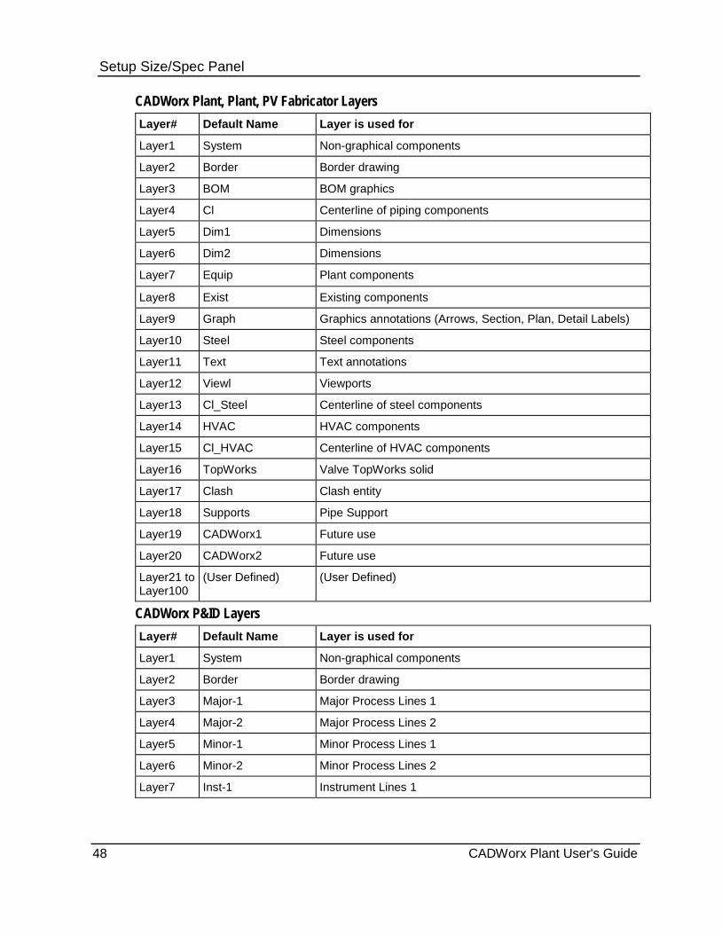
Setup Size/Spec Panel CADWorx Plant, Plant, PV Fabricator Layers Layer# Default Name Layer is used for
Layer1 System Non-graphical components
Layer2 Border Border drawing
Layer3 BOM BOM graphics
Layer4 Cl Centerline of piping components
Layer5 Dim1 Dimensions
Layer6 Dim2 Dimensions
Layer7 Equip Plant components
Layer8 Exist Existing components
Layer9 Graph Graphics annotations (Arrows, Section, Plan, Detail Labels)
Layer10 Steel Steel components
Layer11 Text Text annotations
Layer12 Viewl Viewports
Layer13 Cl_Steel Centerline of steel components
Layer14 HVAC HVAC components
Layer15 Cl_HVAC Centerline of HVAC components
Layer16 TopWorks Valve TopWorks solid
Layer17 Clash Clash entity
Layer18 Supports Pipe Support
Layer19 CADWorx1 Future use
Layer20 CADWorx2 Future use
Layer21 to Layer100
(User Defined) (User Defined)
CADWorx P&ID Layers Layer# Default Name Layer is used for
Layer1 System Non-graphical components
Layer2 Border Border drawing
Layer3 Major-1 Major Process Lines 1
Layer4 Major-2 Major Process Lines 2
Layer5 Minor-1 Minor Process Lines 1
Layer6 Minor-2 Minor Process Lines 2
Layer7 Inst-1 Instrument Lines 1
48 CADWorx Plant User's Guide
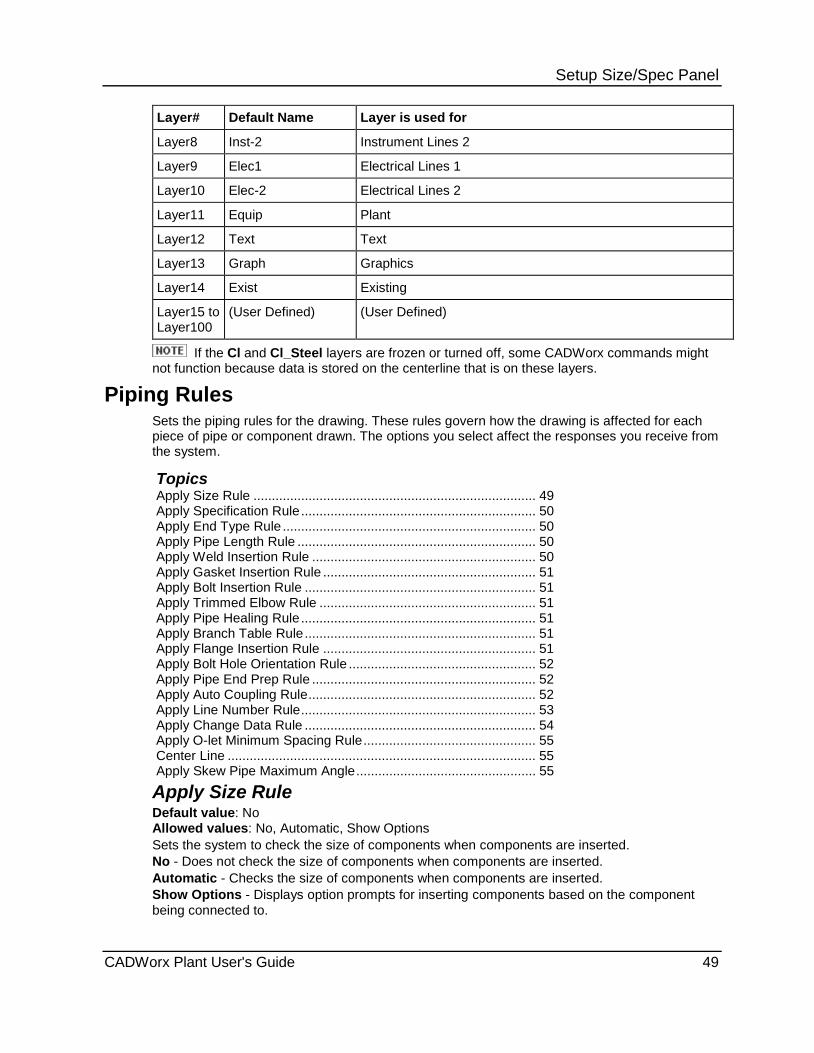
Setup Size/Spec Panel Layer# Default Name Layer is used for
Layer8 Inst-2 Instrument Lines 2
Layer9 Elec1 Electrical Lines 1
Layer10 Elec-2 Electrical Lines 2
Layer11 Equip Plant
Layer12 Text Text
Layer13 Graph Graphics
Layer14 Exist Existing
Layer15 to Layer100
(User Defined) (User Defined)
If the Cl and Cl_Steel layers are frozen or turned off, some CADWorx commands might not function because data is stored on the centerline that is on these layers.
Piping Rules Sets the piping rules for the drawing. These rules govern how the drawing is affected for each piece of pipe or component drawn. The options you select affect the responses you receive from the system.
Topics Apply Size Rule ............................................................................. 49 Apply Specification Rule ................................................................ 50 Apply End Type Rule ..................................................................... 50 Apply Pipe Length Rule ................................................................. 50 Apply Weld Insertion Rule ............................................................. 50 Apply Gasket Insertion Rule .......................................................... 51 Apply Bolt Insertion Rule ............................................................... 51 Apply Trimmed Elbow Rule ........................................................... 51 Apply Pipe Healing Rule ................................................................ 51 Apply Branch Table Rule ............................................................... 51 Apply Flange Insertion Rule .......................................................... 51 Apply Bolt Hole Orientation Rule ................................................... 52 Apply Pipe End Prep Rule ............................................................. 52 Apply Auto Coupling Rule .............................................................. 52 Apply Line Number Rule ................................................................ 53 Apply Change Data Rule ............................................................... 54 Apply O-let Minimum Spacing Rule ............................................... 55 Center Line .................................................................................... 55 Apply Skew Pipe Maximum Angle ................................................. 55
Apply Size Rule Default value: No Allowed values: No, Automatic, Show Options Sets the system to check the size of components when components are inserted. No - Does not check the size of components when components are inserted. Automatic - Checks the size of components when components are inserted. Show Options - Displays option prompts for inserting components based on the component being connected to.
CADWorx Plant User's Guide 49

Setup Size/Spec Panel Apply Specification Rule Default value: No Allowed values: No, Automatic, Show Options
Sets the system to check the specification of components when components are inserted.
No - Does not check the specification of components when components are inserted.
Automatic - Checks the specification of components when components are inserted.
Show Options - Displays option prompts for inserting components based on the component being connected to.
Apply End Type Rule Default value: No Allowed values: No, Automatic, Show Options
Sets the system to check the connection end type between two components based on the Matching End Types Table.
No - Does not check the connection of components when components are inserted.
Automatic - Checks the connection of components when components are inserted.
Show Options - Displays option prompts for inserting components based on the other components connection.
Apply Pipe Length Rule Default value: No Allowed values: No, Automatic, Show Options
Sets the system to check the pipe length when pipe is inserted.
No - Does not check the pipe length of components when components are inserted.
Automatic - Checks the pipe length of components when components are inserted.
Show Options - Displays option prompts for inserting components based on the component being connected to.
Apply Weld Insertion Rule Default value: No Allowed values: No, Automatic - Buttweld Only, Automatic - Socket Weld Only, Automatic - Buttweld and Socket Weld
Specifies auto insert of weld gap to components.
No - Does not insert weld gaps.
Automatic - Buttweld Only - Inserts weld gaps on buttweld connections only.
Automatic - Socket Weld Only - Inserts weld gaps on socket weld connections only.
Automatic - Buttweld and Socket Weld - Inserts weld gaps on buttweld and socket weld connections.
50 CADWorx Plant User's Guide

Setup Size/Spec Panel Apply Gasket Insertion Rule Default value: No Allowed values: No or Automatic
Inserts a gasket to a component automatically when needed.
No - Does not insert gaskets automatically to valves or flanges.
Automatic - Inserts gaskets automatically to valves or flanges.
Apply Bolt Insertion Rule Default value: No Allowed values: No or Automatic Inserts bolts to flanges automatically. No - Does not insert bolts automatically to valves or flanges. Automatic - Inserts bolts automatically to valves or flanges.
Apply Trimmed Elbow Rule Default value: No Allowed values: No or Automatic Places trimmed buttweld elbows in the drawing when using ROUTE. No - Does not allow for trimmed buttweld elbows. Automatic - Router allows for trimmed buttweld elbows.
Apply Pipe Healing Rule Default value: No Allowed values: No or Automatic Heals buttweld pipe when in-line components are erased. No - Does not heal buttweld pipe for in-line components when erased. Automatic - Heals buttweld pipe for in-line components when erased.
Apply Branch Table Rule Default value: No Allowed values: No or Automatic Sets the system to check the branch table when branch components are inserted. No - Does not check the branch table. Automatic - Checks the branch table when branch components are inserted.
Apply Flange Insertion Rule Default value: No Allowed values: No, Automatic - Use Spec Setting, Automatic - Flange Socket Weld, Automatic - Flange Threaded, Automatic - Long Weld Neck, Automatic - Flange Weld Neck, Automatic - Flange Slip On, Show Options Controls the rule of automatically inserting a flange. Sets the system for automatic type and insertion of flanges. No - Does not allow for automatic insertion of a flange. Automatic - Inserts selected flange type automatically. Show Options - Displays option prompts for inserting components based on the component being connected to.
CADWorx Plant User's Guide 51

Setup Size/Spec Panel Apply Bolt Hole Orientation Rule Default value: Automatic - 2 Holes Allowed values: Automatic - 1 Hole, Automatic - 2 Holes, Show Options - Specify Input Angle
Specifies the bolt hole orientation of a flange.
Apply Pipe End Prep Rule Default value: No Allowed values: No, Automatic, Show Options
Sets the end preparation of connections in conjunction with PipeDescriptionCat. The description displays in the Long annotation of the Component Edit dialog box.
No - Does not set the end prep of components when components are inserted.
Automatic - Sets the pipe end prep of components when components are inserted.
Show Options - Displays option prompts to set or not set the pipe end prep.
The PipeDescriptionCat must be set to 1 through 6 and the Apply Pipe End Prep Rule
must be set to Automatic for the pipe end preparation descriptions to appear.
If the PipeDescriptionCat is set to 0 and the Apply Pipe End Prep Rule is set to Automatic the pipe end preparation description is not set and does not display.
If the PipeDescriptionCat is set to 1 through 6 and the Apply Pipe End Prep Rule is set to No the pipe end preparation description is not set and does not display.
If the PipeDescriptionCat is set to 1 through 6 and the Apply Pipe End Prep Rule is set to Show Options you are only prompted to set the pipe end preparation when inserting single pipe using the PIPW1 command. Selecting No does not set the pipe end preparation and does not display a description. This is the case even with the PipeDescriptionCat set to 1 through 6. Selecting Yes displays the description unless the PipeDescriptionCat is set to 0.
For more information, see PipeDescriptionCat (on page 41).
Apply Auto Coupling Rule Default value: No Allowed values: No, Automatic - Pipe Breaks Only, Automatic - All Connections, Show Options
Sets the system to insert a coupling when routing components.
No - Does not add a coupling when routing components.
Automatic - Pipe Breaks Only - Adds a coupling when routing components with socket weld or threaded piping, when the pipe breaks at the maximum length. You must set the Apply Pipe Length Rule to Automatic or Show Options or couplings are not added.
Automatic - All Connections - Adds a coupling at all connections while routing.
Show Options - Displays option prompts, when routing, to inset a coupling. This happens when using socket weld or threaded piping or when the pipe breaks at the maximum length. You must set the Apply Pipe Length Rule to Automatic or Show Options or couplings are not added.
52 CADWorx Plant User's Guide

Setup Size/Spec Panel Apply Line Number Rule Default value: Always Inherit Allowed values: Always Inherit, Show Options
Sets the system to check the line number of in-line components when a component is inserted based on the setting in line number Setup and according to the table below.
Always Inherit - Automatically inherits the line number of in-line components when a component is inserted.
Show Options - Displays option prompts for inheriting the line number on in-line components when components are inserted.
Line Number System Setup Apply Line Number Rule Setting Effect
System Off Always Inherit No Line Number Rule is applied
Show Options No Line Number Rule is applied
System On (Dynamic Size/Spec)
Always Inherit Inherit all header/parent line number parameters except the dynamic one such as Size and Spec
Show Options Show 3 different options:
1. Exact copy of parent line number.
2. Dynamic parent line number (the same parent line number except for the size and spec).
3. Current line number setup as listed in the Line Number setup.
System On (Static Size /Spec)
Always Inherit Inherit exact copy of header/parent line number
Show Options Show 2 options:
1. Exact copy of header/parent line number.
2. Current line number as shown in the Line Number setup.
For more information about Line Number System setup, see Line Numbering System Dialog Box (on page 146).
CADWorx Plant User's Guide 53

Setup Size/Spec Panel Apply Change Data Rule Default value: Custom Data Allowed values: Checked items in the Apply Change Data Rule dialog box display here
Sets the system for items that do not update when using Change Size, Change Spec, or converting from project data.
See Also Apply Change Data Rule Dialog Box (on page 54)
Apply Change Data Rule Dialog Box Enables you to select the items that do not update when using CHANGESPEC, CHANGESIZE, or CONVERTFROMPRJDATA.
Alpha size - Turns the alpha size update on or off. The software updates the Alpha size in the Alpha size box in the Component Edit dialog box.
Short Description - Turns the short description update on or off. The software updates the Short Description in the Short annotation box in the Component Edit dialog box.
Long description - Turns the long description update on or off. The software updates the Long description in the Long annotation box in the Component Edit dialog box.
Tag - Turns the tag update on or off. The software updates the Tag in the Tag box in the Component Edit dialog box.
Database Codes - Turns the database codes update on or off. The software updates the Database Codes in the Code box in the Component Edit dialog box.
Custom Data - Turns the custom data update on or off. The software updates the Custom Data in the Component Custom Data dialog box. Click Custom Data in the Component Edit dialog box to display the Component Custom Data dialog box. You can create Custom Data in the Specification Editor with the Custom Data options.
Line Number - Turns the line number update on or off. The software updates the Line Number in the Line Number box in the Component Edit dialog box.
Layer/color - Turns the layer and color update on or off. When Layer/color is on, the software updates the layer and color to the component. If Layer/color is off, the component in the model does not change its layer or its color when you convert from the project data. Use the LayerByLineNumber (on page 39) Configuration Setting to specify the layers for component updates during Change Size or Change Spec.
Layer/color always updates when you use Change Size or Change Spec.
Select / deselect all - Checks or clears all check boxes in the Apply Change Data Rule dialog box. This is useful when you want to update everything or nothing.
Change the Data Rule update 1. Select the Apply Change Data Rule ellipsis.
2. Select the items that you do not want updated. If you want to update all items, clear all check boxes.
3. Click OK.
54 CADWorx Plant User's Guide

Setup Size/Spec Panel Apply O-let Minimum Spacing Rule Default value: 0.2500 Allowed values: spacing values
Enables you to control the overlap distance between o-lets and weld gaps.
Center Line Default value: On Allowed values: On, Off
Indicates whether the centerline of the components displays.
Apply Skew Pipe Maximum Angle Default value: 15.0000 Allowed values: angle values 1 to 179
Enables you to control the maximum angle allowed when routing skewed piping. To route skewed piping, see Auto Route (on page 221) and Route skewed pipe (on page 224).
Convert Legacy Drawing Default value: Off Allowed values: Off, Automatic, Show Options
Enables you to convert legacy drawing components to smart components.
Convert Mode - Sets the software to recognize whether the drawing is a legacy drawing and convert it. There are three options:
Off - Indicates the software does not convert the legacy drawing when it is opened.
Automatic - Specifies that the software automatically converts the drawing to smart components when you open the drawing.
Show Options - Indicates that the software prompts you to convert the drawing to smart components when you open the drawing.
Use new spec data - Specifies whether CADWorx data is pulled from the project file or the legacy components when a conversion is completed.
Yes - Indicates the software pulls data from the project file during the conversion.
No - Indicates the software pulls data from the legacy component during conversion.
Refresh all open palettes to update contents after running the CONVERTCADWORXLEGACYDWGS command. See Also CADWorx Legacy Drawing - Match Specifications dialog box (on page 56)
CADWorx Plant User's Guide 55
Setup Size/Spec Panel CADWorx Legacy Drawing - Match Specifications Dialog Box CADWorx Plant I tab: Setup Size/Spec > Setup > Convert Legacy Drawing and then set Convert Mode to Show Options
Command line: CONVERTCADWORXLEGACYDWGS
Converts the components of a legacy drawing to smart components.
Available specifications in project - Specifies if there are any available specifications in the selected project for conversion.
Legacy specification used in model - Specifies the specifications that the software uses in the legacy model.
Match - Matches the selected specification in Available specifications in project to the specification listed in Legacy specification used in model.
Auto Match - Automatically matches the specification used in the legacy model without selecting a specification from the Available specifications in project box.
Backup current drawing - Creates a backup of the legacy drawing in the folder where the legacy drawing resides.
Use new spec data - Specifies whether CADWorx data is pulled from the project file or the legacy components when a conversion is completed. When Use new spec data is selected, data is pulled from the selected specification in Current Project.
Current Project - Specifies the current project from which the software converts the legacy drawings.
Browse - Enables you to select a current project. OK - Accepts the settings and converts the model. Cancel - Cancels the legacy conversion. Help - Accesses the online help file. Convert Legacy using Automatic option Set Convert Mode to Automatic.
The software converts the drawing into smart components when a legacy drawing is opened.
Convert Legacy using Show Options option 1. Set Convert Mode to Show Options. For more information, see Convert Legacy Drawing
(on page 55). The CADWorx Legacy Drawing - Match Specifications dialog box displays.
2. Click Browse. The Open dialog box displays.
3. Select a PRJ file, and click Open. The specifications display in the Available specifications in project box.
4. Select a specification used in the model in the Legacy specification used in model box.
5. Select a specification in the Available specifications in project box, and click Match.
Clicking Auto Match automatically selects the matching specification for the drawing based on the specification used in the legacy drawing. If you want to use a different specification for the drawing, such as 300, you must click Match instead of Auto Match.
56 CADWorx Plant User's Guide
Setup Size/Spec Panel 6. Select Backup current drawing to create a backup the drawing. This is the default option.
OR
Clear Backup current drawing so that a backup of the drawing is not created.
7. Select Use new spec data to use the spec data from the current project. This is the default option.
OR
Clear Use new spec data to use the spec data from the legacy drawing.
8. Click OK.
The software converts the drawing into a 2013 components.
Convert Legacy using the CONVERTCADWORXLEGACYDWGS command 1. Type CONVERTCADWORXLEGACYDWGS on the command line, and press ENTER.
The CADWorx Legacy Drawing - Match Specifications dialog box displays.
2. Click Browse.
The Open dialog box displays.
3. Select a .prj file, and click Open.
The specifications display in the Available specifications in project box.
4. Select a specification used in the model in the Legacy specification used in model box.
5. Select a specification in the Available specifications in project box, and click Match.
Clicking Auto Match indicates that the software automatically selects the matching specification for the drawing based on the specification used in the legacy drawing. If you want to use a different specification for the drawing, such as 300, you must click Match instead of Auto Match.
6. Select Backup current drawing to create a backup the drawing. This is the default option.
OR
Clear Backup current drawing so that a backup of the drawing is not created.
7. Select Use new spec data to use the spec data from the current project. This is the default option.
OR
Clear Use new spec data to use the spec data from the legacy drawing.
8. Click OK.
The software converts the drawing into smart components.
If you notice that a component does not convert to a smart component then the component
may not be listed in the specification that you have chosen.
The software alerts you with a message if you do not have any legacy data in the drawing.
You must convert an inch drawing to an inch specification and a metric drawing to a metric specification.
CADWorx Plant User's Guide 57
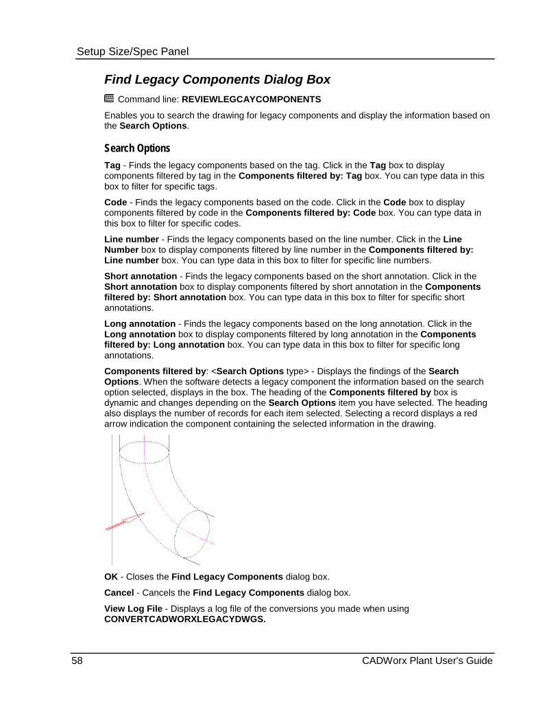
Setup Size/Spec Panel Find Legacy Components Dialog Box
Command line: REVIEWLEGCAYCOMPONENTS
Enables you to search the drawing for legacy components and display the information based on the Search Options.
Search Options Tag - Finds the legacy components based on the tag. Click in the Tag box to display components filtered by tag in the Components filtered by: Tag box. You can type data in this box to filter for specific tags.
Code - Finds the legacy components based on the code. Click in the Code box to display components filtered by code in the Components filtered by: Code box. You can type data in this box to filter for specific codes.
Line number - Finds the legacy components based on the line number. Click in the Line Number box to display components filtered by line number in the Components filtered by: Line number box. You can type data in this box to filter for specific line numbers.
Short annotation - Finds the legacy components based on the short annotation. Click in the Short annotation box to display components filtered by short annotation in the Components filtered by: Short annotation box. You can type data in this box to filter for specific short annotations.
Long annotation - Finds the legacy components based on the long annotation. Click in the Long annotation box to display components filtered by long annotation in the Components filtered by: Long annotation box. You can type data in this box to filter for specific long annotations.
Components filtered by: <Search Options type> - Displays the findings of the Search Options. When the software detects a legacy component the information based on the search option selected, displays in the box. The heading of the Components filtered by box is dynamic and changes depending on the Search Options item you have selected. The heading also displays the number of records for each item selected. Selecting a record displays a red arrow indication the component containing the selected information in the drawing.
OK - Closes the Find Legacy Components dialog box.
Cancel - Cancels the Find Legacy Components dialog box.
View Log File - Displays a log file of the conversions you made when using CONVERTCADWORXLEGACYDWGS.
58 CADWorx Plant User's Guide
Setup Size/Spec Panel
Specification and Size Sets the specification and size using the Set Specification and Size dialog box. For more information, see Set Specification and Size (on page 46).
Optional Items CADWorx Plant I tab: Setup Size/Spec > Optional Items
Setting toolbar: Specification Option Toggle
Plant menu: Accessory > Specifications > Optional Items
Command line: SPECOPTION
Places a component on the drawing when the component type in the specification has an optional component (such as when a 300 lb. orifice flange is in the 150 lb. specification).
Click the command to toggle between two methods:
1. The command line message is:
All components will be dialoged...
When a component type is selected, all components of that component type appear in the Optional component dialog box. For more information, see Optional Component Dialog Box (on page 59).
2. The command line message is:
Specification dialog turned off...
When a component type is selected, the default component is selected for placement on the drawing. The Optional component dialog box does not appear unless the component size is out of the specification range or the component is not allowed by the specification. You can then select a component in the range. For more information, see Optional Component Dialog Box (on page 59).
Optional Component Dialog Box Specifies components for placement. Status, start size, end size, tag, long description, and short description are displayed for each component.
OK - Places the selected component on the drawing.
Default - Changes the selected component to the default component.
Using SpecSizeOverride When the SpecSizeOverride (on page 43) variable is off, sizes are restricted to the specification range. If the selected size is not within the range, OK and Default are not available.
If SpecSizeOverride is on, the dialog box appears if the component size is not in the range. You can then select the needed component even when it is out of range.
CADWorx Plant User's Guide 59

Setup Size/Spec Panel The following table summarizes the dialog box behavior.
Component in specification?
Size in specification?
Dialog box appears?
SpecSizeOverride variable status
Dialog box behavior
Yes Yes No Off = 0 Normal operation.
Yes No No Off = 0 Error message.
Yes No No On = 1 Error message, but you can override.
Yes Yes Yes Off = 0 Dialog box shows all components including optional components, but does not allow override.
Yes No Yes Off = 0 Dialog box shows all components but OK is not available for components not in size range.
Yes No Yes On = 1 Dialog box shows all components and allows override.
No n/a No Off = 0 Error message.
You can use the Spec Editor to change components to optional components. For more information, see Spec Editor (on page 89).
Size CADWorx Plant I tab: Setup Size/Spec > Size
Setting toolbar: Size
Plant menu: Utility > Set Component > Size
Command line: COMP2SIZE
Specifies the main and reduction size by selecting a component with the needed sizes. Reduction size is not set if it has not been set on the selected component. You can optionally reverse the main and reduction sizes.
Spec CADWorx Plant I tab: Setup Size/Spec > Spec
Setting toolbar: Spec
Plant menu: Utility > Set Component > Spec
Command line: COMP2SPEC
Specifies the current specification by selecting a component using the needed specification.
60 CADWorx Plant User's Guide
Setup Size/Spec Panel
Size-Spec CADWorx Plant I tab: Setup Size/Spec > Size-Spec
Setting toolbar: Size-Spec
Plant menu: Utility > Set Component > Size-Spec
Command line: COMP2SIZESPEC
Specifies the main size, reduction size, and specification by selecting a component with the needed values. Reduction size is not set if it has not been set on the selected component. You can optionally reverse the main and reduction sizes.
All Setting toolbar: All
Plant menu: Utility > Set Component > All
Command line: COMP2ALL
Specifies the main size, reduction size, specification, and line number by selecting a component with the needed values.
This option requires that you set the LineNumberSystem (on page 41) variable to 2. This is the same as having the System On (Static Size/Spec) option in the Line Numbering System dialog box selected. For more information, see Line Numbering System Dialog Box (on page 146).
Editor Creates, views, and modifies specifications. For more information, see Spec Editor (on page 89).
Change Size CADWorx Plant I tab: Setup Size/Spec > Change Size
Command Line: CHANGESIZE
Changes the size of the selected components based on available sizes. Sizes are based on the specification project you choose when initially setting up the drawing. This command has two main functions Automatic or Manual.
Automatic - Automatically changes the entire component to the chosen size.
The Change Size command only changes the size of the line until it reaches a reducer. The software provides two options to replace a reducer to match the size change. The pipeline on the other side of the reducer maintains its size. The only way to change the size of the pipeline on both sides of a reducer is to select the reducer itself.
Manual - Changes only the selected components to the chosen size.
When using the manual option, the software forces you to select reducers for adjacent components that are not the same size. The manual option does not stop size changes at any point based on another component. However, unless the line on the other side of a reducer is selected it is not changed.
CADWorx Plant User's Guide 61

Setup Size/Spec Panel Large - Changes the large side of the component and anything attached to that side. This is only an option when using Automatic.
Small - Changes the small side of the component and anything attached to that side. This is only an option when using Automatic.
Both - Changes both sides of the component and anything attached to those sides. This is only an option when using Automatic.
Change current component - Changes the component to match the size change. add Reducing component - Displays a list of reducing components. add Reducer at branch - Adds a reducer to a branch component. This option is available when changing the size of a branch component. BOP - Places the changed size piping at the bottom of pipe. TOP - Places the changed size piping at the top of pipe. Current - Places the changed size piping at the current location. caNcel - Does not change the size and cancels out.
When you change size of a pipe attached to a pipe support, the pipe support also changes size to coincide with the piping.
What do you want to do? Change the size automatically (on page 62) Change the size manually (on page 63) Change the size of a reducer and the pipes automatically (on page 63) Change the size of a reducer and the pipes manually (on page 64) Change the size of a model with branch connections automatically (on page 64) Change tee sizes automatically (on page 65) Change tee sizes manually (on page 66)
Change the size automatically 1. Click Change Size . Alternatively, type CHANGESIZE on the command line, and press
ENTER.
2. Press ENTER for automatic.
3. Select a component.
4. Select a size from the list that displays.
If a size is not available in the catalog for a component, the process stops, forcing you to start over.
5. Select a component to keep its position, or press ENTER to finish.
If prompted select, the BOP, TOP, or Current after selecting the piping to keep the position.
The software continues to prompt you for selection of a component until you press ENTER to finish.
The entire drawing changes its size.
62 CADWorx Plant User's Guide
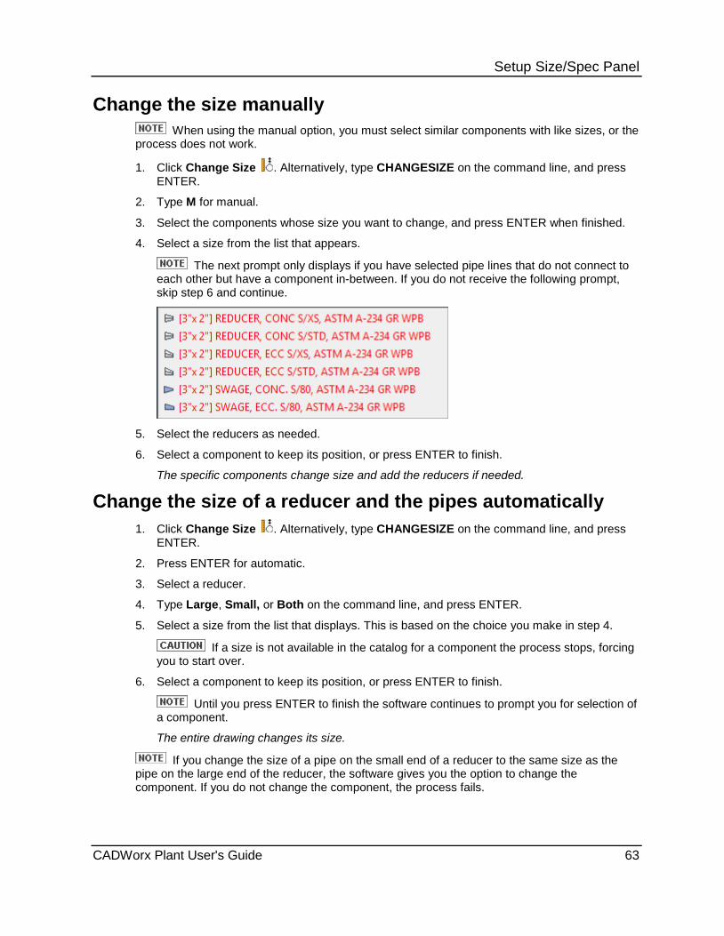
Setup Size/Spec Panel
Change the size manually When using the manual option, you must select similar components with like sizes, or the
process does not work.
1. Click Change Size . Alternatively, type CHANGESIZE on the command line, and press ENTER.
2. Type M for manual.
3. Select the components whose size you want to change, and press ENTER when finished.
4. Select a size from the list that appears.
The next prompt only displays if you have selected pipe lines that do not connect to each other but have a component in-between. If you do not receive the following prompt, skip step 6 and continue.
5. Select the reducers as needed.
6. Select a component to keep its position, or press ENTER to finish.
The specific components change size and add the reducers if needed.
Change the size of a reducer and the pipes automatically 1. Click Change Size . Alternatively, type CHANGESIZE on the command line, and press
ENTER.
2. Press ENTER for automatic.
3. Select a reducer.
4. Type Large, Small, or Both on the command line, and press ENTER.
5. Select a size from the list that displays. This is based on the choice you make in step 4.
If a size is not available in the catalog for a component the process stops, forcing you to start over.
6. Select a component to keep its position, or press ENTER to finish.
Until you press ENTER to finish the software continues to prompt you for selection of a component.
The entire drawing changes its size.
If you change the size of a pipe on the small end of a reducer to the same size as the pipe on the large end of the reducer, the software gives you the option to change the component. If you do not change the component, the process fails.
CADWorx Plant User's Guide 63
Setup Size/Spec Panel
Change the size of a reducer and the pipes manually Use this option when you want to change the size of more than one reducer and the pipe
lines to multiple sizes.
1. Click Change Size . Alternatively, type CHANGESIZE on the command line, and press ENTER.
2. Type M for manual.
3. Select one or more reducers and press ENTER.
If you select more than one you might not be prompted for the sides of the reducer. This depends on the location of the chosen reducers.
4. If applicable, type Large, Small, or Both on the command line, and then press ENTER.
5. Select a size from the list. This list continues to show up for as many components as you selected.
If a size is not available in the catalog for a component the process stops, forcing you to start over.
6. Select a component to keep its position, or press ENTER to finish.
Until you press ENTER to finish the software continues to prompt you for selection of a component.
The selected components change size.
If you change the size of a pipe on the small end of a reducer to the same size as the pipe on the large end of the reducer, the software gives you the option to change the component. If you do not change the component, the process fails.
Change the size of a model with branch connections automatically
1. Click Change Size . Alternatively, type CHANGESIZE on the command line, and press ENTER.
2. Press ENTER for automatic. 3. Select a component. 4. Select a size from the list that displays.
If a size is not available in the catalog for a component, the process stops, forcing you to start over.
5. Select all the branches in the model. If you do not select all the branches the software prompts you to change the
component. If you select No, the process fails. You may also be prompted if the size does not exist.
6. Select a component, or press ENTER to finish. 7. If prompted to fix the pipe by BOP, TOP, or Current, type an option, and press ENTER. 8. Select a component to keep its position, or press ENTER to finish.
Until you press ENTER to finish the software continues to prompt you for selection of a component.
The selected system changes size.
64 CADWorx Plant User's Guide
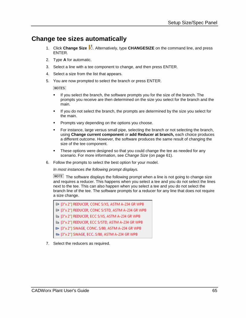
Setup Size/Spec Panel
Change tee sizes automatically 1. Click Change Size . Alternatively, type CHANGESIZE on the command line, and press
ENTER.
2. Type A for automatic.
3. Select a line with a tee component to change, and then press ENTER.
4. Select a size from the list that appears.
5. You are now prompted to select the branch or press ENTER.
If you select the branch, the software prompts you for the size of the branch. The
prompts you receive are then determined on the size you select for the branch and the main.
If you do not select the branch, the prompts are determined by the size you select for the main.
Prompts vary depending on the options you choose.
For instance, large versus small pipe, selecting the branch or not selecting the branch, using Change current component or add Reducer at branch, each choice produces a different outcome. However, the software produces the same result of changing the size of the tee component.
These options were designed so that you could change the tee as needed for any scenario. For more information, see Change Size (on page 61).
6. Follow the prompts to select the best option for your model.
In most instances the following prompt displays.
The software displays the following prompt when a line is not going to change size and requires a reducer. This happens when you select a tee and you do not select the lines next to the tee. This can also happen when you select a tee and you do not select the branch line of the tee. The software prompts for a reducer for any line that does not require a size change.
7. Select the reducers as required.
CADWorx Plant User's Guide 65
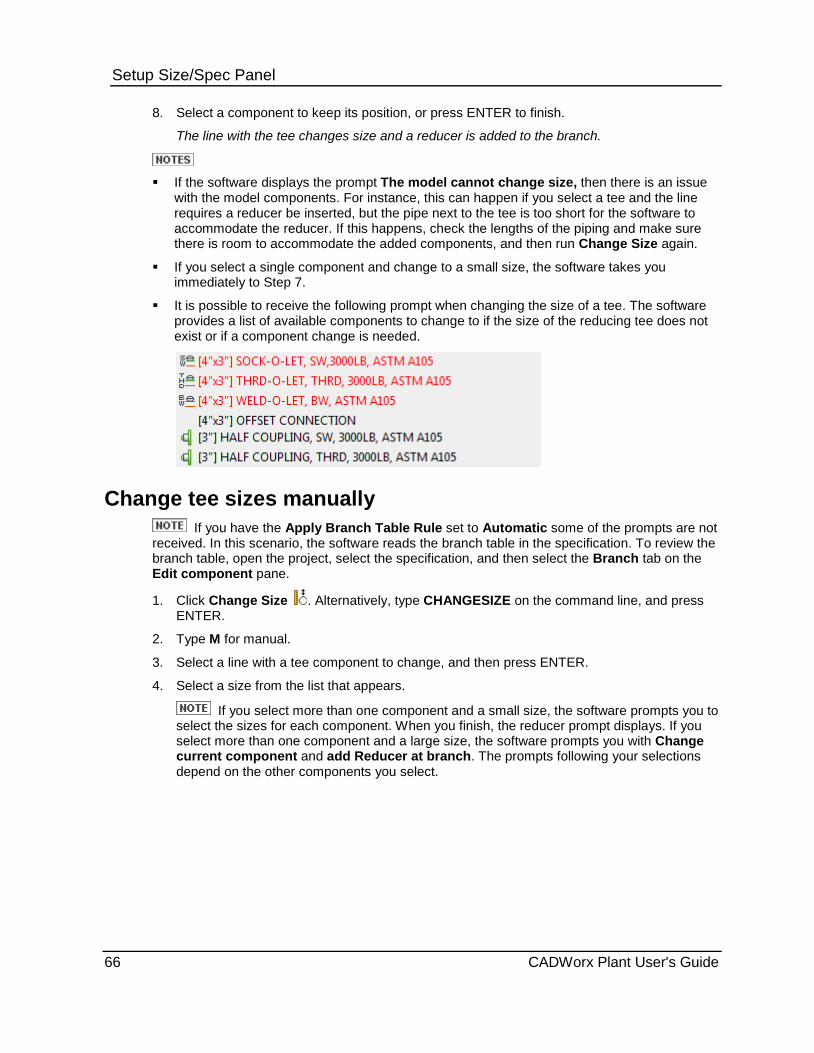
Setup Size/Spec Panel 8. Select a component to keep its position, or press ENTER to finish.
The line with the tee changes size and a reducer is added to the branch.
If the software displays the prompt The model cannot change size, then there is an issue
with the model components. For instance, this can happen if you select a tee and the line requires a reducer be inserted, but the pipe next to the tee is too short for the software to accommodate the reducer. If this happens, check the lengths of the piping and make sure there is room to accommodate the added components, and then run Change Size again.
If you select a single component and change to a small size, the software takes you immediately to Step 7.
It is possible to receive the following prompt when changing the size of a tee. The software provides a list of available components to change to if the size of the reducing tee does not exist or if a component change is needed.
Change tee sizes manually If you have the Apply Branch Table Rule set to Automatic some of the prompts are not
received. In this scenario, the software reads the branch table in the specification. To review the branch table, open the project, select the specification, and then select the Branch tab on the Edit component pane.
1. Click Change Size . Alternatively, type CHANGESIZE on the command line, and press ENTER.
2. Type M for manual.
3. Select a line with a tee component to change, and then press ENTER.
4. Select a size from the list that appears.
If you select more than one component and a small size, the software prompts you to select the sizes for each component. When you finish, the reducer prompt displays. If you select more than one component and a large size, the software prompts you with Change current component and add Reducer at branch. The prompts following your selections depend on the other components you select.
66 CADWorx Plant User's Guide

Setup Size/Spec Panel 5. Follow the prompts to select the best option for your model.
In most instances the following prompt displays.
The software displays the following prompt when a line is not going to change size and requires a reducer. This happens, when you select a tee and you do not select the lines next to the tee. This can also happen, when you select a tee and you do not select the branch line of the tee. The software prompts for a reducer for any line that does not require a size change.
6. Select the reducers as required.
7. Select a component to keep its position, or press ENTER to finish.
The tee changes size.
If the software displays the prompt The model cannot change size, then there is an issue
with the model components. For instance, this can happen if you select a tee and the line requires a reducer to be inserted. However, the pipe next to the tee is too short for the software to accommodate the reducer. If this happens, check the lengths of the piping and make sure there is room to accommodate the added components, and then run Change Size again.
If you select a single tee and change to a small size, the software takes you immediately to step 6.
It is possible to receive the following prompt when changing the size of a tee. The software provides a list of available components if the size of the reducing tee does not exist or if a component change is needed.
CADWorx Plant User's Guide 67

Setup Size/Spec Panel
Change Specification CADWorx Plant I tab: Setup Size/Spec > Change Spec
Command Line: CHANGESPEC
Changes the specification of the selected components. The software determines the change specification based on the size and type of the selected component. The Change Spec command has two modes either Automatic or Manual.
Automatic - Changes all the components on the selected line to the chosen specification automatically, depending on the following conditions.
The Automatic option only changes the specification assigned to the system until it reaches another specification.
If there is only one matching default component in the chosen specification, the software chooses the default component.
If there are multiple default components matching the component in the chosen specification, the software provides a list of all the default components.
If there is only one optional component matching the component in the chosen specification and no matching default components, the software selects the optional component.
If there are multiple matching optional components in the chosen specification and no matching default components, the software displays a list of optional components for you to choose. When the list displays, the component highlights in the drawing.
If there are default and optional components of the same type, you must use the Manual option to select an optional component.
Manual - Changes only the selected components to the chosen specification. If there is only one matching component in the chosen specification, the software selects the default. If there is only one optional component in the chosen specification and no default component, the software selects the optional component. If there is more than one matching component in the chosen specification, the software provides you a list of the components. The software changes any component you select to the component information you select from the list. When the list displays, the component highlights in the drawing.
What do you want to do? Change the specification automatically (on page 68)
Change the specification manually (on page 69)
Change the specification of a model with branches automatically (on page 70)
Change the specification automatically 1. Click Change Spec . Alternatively, type CHANGESPEC on the command line, and press
ENTER.
2. Press ENTER for automatic.
3. Select a pipeline.
68 CADWorx Plant User's Guide
Setup Size/Spec Panel 4. Select a specification.
The software selects the default component if there is only one default component.
OR
The software selects the optional component if there is no default and only one optional.
OR
A list of components displays.
This list only displays when there are multiple components matching the component in the chosen specification. Automatic option only displays the default components if there are matching default components found, even if matching optional components exist. The default component takes higher priority. The only time the software displays an optional component (or list of components) is when there are no matching default components found in the chosen specification. If the software selects the only available default component, skip to step 6.
5. Select the component you need.
6. Select a component to keep its position, or press ENTER to finish.
The software continues to prompt you for selection of a component until you press ENTER to finish.
The software changes the specification for the selection.
Change the specification manually 1. Click Change Spec . Alternatively, type CHANGESPEC on the command line, and press
ENTER.
2. Type M for manual.
3. Select the components whose specification you want to change, and press ENTER when finished.
4. Select a specification.
The software selects the default component if there is only one matching default component and no matching optional components.
When you use the Manual option, you can select a single component or more than one component. If you select more than one component, it is possible to get both responses in step 4. One component could only have one default, but another component could have a multitude of matching components. OR A list of components displays.
This list only displays when there are multiple matching components. For instance, if you have five of the same type of pipe but with different schedules, the software displays all the matching pipes to choose from. If this list does not display, skip to step 6.
5. Select the component you need. 6. Select a component to keep its position, or press ENTER to finish.
The software continues to prompt you for selection of a component until you press ENTER to finish.
The specification to the selected components is changed.
CADWorx Plant User's Guide 69

Setup Size/Spec Panel
Change the specification of a model with branches automatically
1. Click Change Spec . Alternatively, type CHANGESPEC on the command line, and press ENTER.
2. Press ENTER for automatic.
3. Select a pipeline.
4. Select a specification.
The software selects the default component if there is only one default component.
OR
The software selects the optional component if there is no default and only one optional. OR A list of components displays.
This list only displays when there are multiple components matching the component in the chosen specification. Automatic option only displays the default components if there are matching default components found, even if matching optional components exist. The default component takes higher priority. The only time the software displays an optional component (or list of components) is when there are no matching default components found in the chosen specification. If the software selects the only available default component, skip to step 6.
5. Select the component you need.
6. Select the branches.
If you do not select the branches in step 6 the specification changes only for the tee or cross components. It does not change for the branch piping.
7. Select a component to keep its position, or press ENTER to finish.
The software continues to prompt you for selection of a component until you press ENTER to finish.
The specification assignment for the selected system is changed. If there is a reducer in the system, the new specification assignment only applies up to and including the reducer, not the pipeline on the other side of the reducer.
Local Edit CADWorx Plant I tab: Setup Size/Spec > Local Edit
Setting toolbar: Component Edit
Plant menu: Utility > Component Edit > Local Edit
Command line: CEDIT
Modifies the properties of an existing component on the drawing. This command displays the Component Edit dialog box.
70 CADWorx Plant User's Guide

Setup Size/Spec Panel Component Edit Dialog Box Specifies properties for a component.
Alpha size - Specifies a size-only description of the component.
Short annotation - Specifies a short description of the component.
Long annotation - Specifies a long description of the component.
Line number - Specifies the line number of the component.
Tag - Specifies a tag for the component.
Code - Specifies a code for the component.
Weight - Specifies the weight per unit of a pipe component.
Sort sequence - Specifies the sort sequence of the component in the bill of material.
Length - Specifies a length for the component.
Component type - Displays the type of the component.
Specification - Displays the specification used by the component.
If Setup is used to create an external database, Synchronize can be used to change the specification in the database. For more information, see Setup Live Database (on page 164) and Synchronize Pipe Database (on page 169).
If using a live database the Alpha Size, Short annotation, Long annotation, Line number, Tag, Code, Weight, Sort sequence, and any Custom Data are updated when you click Synchronize . If you make a change in the database and the SyncOnStartUp (on page 44) is set to Synchronize With Changes Review, then the Synchronize Component dialog box displays and enables you to review the changes to the database and reject or accept the changes. For more information, see Synchronize Pipe Database (on page 169).
Coordinates
World - Calculates pipe length based on the pipe component centerline. This option only affects pipe, nipple, flanged pipe, and tubing components. It does not affect fixed-size components such as elbows or flanges. If a pipe component is stretched, trimmed, or broken, the positions of the components are automatically updated along with the pipe length.
Iso - Specifies the value of Length as the pipe length. The length does not change the drawing graphics, but appears in the bill of material. For more information, see ISO Flag (on page 210).
Miscellaneous
Existing - Specifies that the component is not included in the bill of material. The component symbol is also moved to the Exist layer. In ISOGEN isometric drawings, the component is shown as dotted and dimensioned.
Insulation or CAESAR II - Specifies that this component either has CAESAR II pipe stress analysis information or insulation attached.
BOM Item Type
Fabrication - Specifies a fabrication type of bill of material item.
Erection - Specifies an erection type of bill of material item.
CADWorx Plant User's Guide 71

Setup Size/Spec Panel Offshore - Specifies an offshore type of bill of material item.
Misc - Specifies a miscellaneous type of bill of material item.
The selected item type appears on the bill of materials when the FLAG column is added
using Pipe BOM / DB > Setup . For ISOGEN, you must also sort by the FLAG column to group by type. For more information, see Bill of Material Setup (on page 154) and BOM Sort Order / Accumulation Dialog Box (on page 157).
If Misc is selected when using ISOGEN, then ISOGEN treats the weld gap as a field-fit weld. Use ISOGEN Option Switch 22 to increase the cut piece add-on allowances for field-fit welds.
OK - Saves modifications and closes the dialog box.
Cancel - Cancels the operation without saving modifications, and closes the dialog box.
ISOGEN - Specifies data for the component in an ISOGEN drawing. Opens the ISOGEN Data dialog box.
ISOGEN Data Dialog Box (on page 73)
Custom Data - Specifies custom data created in the Specification Editor and enables you to edit the value. This data can be isolated in the Line View palette.
For more information on creating custom data, see New Field Dialog Box in the CADWorx Spec Editor Users Guide.
Click the link for more information on the Component Custom Data Dialog Box (on page 78).
Remove - Removes CADWorx database attributes from a component, converting it to generic AutoCAD geometry.
Many commands in CADWorx use xdata in the components and do not function if the data is removed.
You can double-click a component to open the Component Edit dialog box.
Modify a component 1. Click Local Edit .
2. In the drawing, select a component.
The Component Edit dialog box appears.
3. Modify properties as needed.
4. Click OK.
72 CADWorx Plant User's Guide

Setup Size/Spec Panel
ISOGEN Data Dialog Box Specifies ISOGEN properties for a component.
Symbol Information
Identifier - Specifies the identifier used by ISOGEN for the component. For more information, see SKEY Information.
Overwrite - Overwrites the default value of ISOGEN Identifier used by CADWorx and uses the value specified in Identifier.
SKEY - Specifies the SKEY used by ISOGEN for the component. For more information, see SKEY Information.
Overwrite - Overwrites the default value of ISOGEN SKEY used by CADWorx and uses the value specified in SKEY.
Message - Specifies the message displayed with the component on the isometric drawing.
Type - Specifies the type of graphic enclosing the message.
CADWorx Plant User's Guide 73

Setup Size/Spec Panel
Message Types
Type Graphic
None No text or graphic
Unboxed Text only
Square
Pointed
Round
Circle
Triangle
Diamond
Double Circle
Ellipse
Text - Specifies the message text.
Spindle / Flat / Support Direction - Specifies a valve spindle direction, an eccentric reducer flat direction, or support direction.
Direction - Specifies the direction. Select North, South, East, West, Up, or Down.
Text - Specifies a text message with details on the direction.
ISOGEN option switch 80 (dimension to valve centers) is only available if the valve has a spindle direction set.
Flow Arrow - Specifies how flow arrows are displayed for valves.
As drawn - Displays the flow arrow in the direction that the pipe was drawn.
Opposite - Displays the flow arrow in the opposite direction.
View - Displays a preview of the flow arrow on the drawing.
ISOGEN option switch 17 controls the display of flow arrows.
Miter Pipe Export Options - Specifies how miter pipe is exported to ISOGEN.
74 CADWorx Plant User's Guide
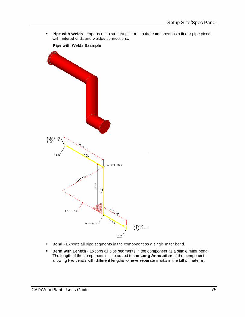
Setup Size/Spec Panel Pipe with Welds - Exports each straight pipe run in the component as a linear pipe piece
with mitered ends and welded connections.
Pipe with Welds Example
Bend - Exports all pipe segments in the component as a single miter bend.
Bend with Length - Exports all pipe segments in the component as a single miter bend. The length of the component is also added to the Long Annotation of the component, allowing two bends with different lengths to have separate marks in the bill of material.
CADWorx Plant User's Guide 75

Setup Size/Spec Panel
Bend with Length Example
Other
Spool - Specifies the spool identification. This value overrides the default spool value created by ISOGEN. Type the required alpha or numeric character.
Sketch - Specifies a .dwg detailed sketch to display with the isometric drawing. For more information on detailed sketches, see the Information Notes.pdf and Detailed Sketches.pdf files in the [Product Folder]\Plant\Isogen\Isogen_Utils folder.
Dim Status - Specifies the dimensioning of individual components. Select Default, Dimensioned, Dotted Dimensioned, or Dotted Undimensioned.
Sheet # - Specifies the sheet number of an ISOGEN drawing. Type the required alpha or numeric character.
Mark - Specifies the mark number for a component. Type the required alpha or numeric character.
76 CADWorx Plant User's Guide

Setup Size/Spec Panel End Connections and Conditions - Specifies a set of conditions for up to four ends (End 1, End 2, End 3, and End 4).
Connection Type - Specifies the type of connection on the end
Connection Types
Connection Types Description Default Condition
Default
BS Ball and Socket Male
BW Butt Weld Unspecified
CL Clamped Male
CP Compression Female
FA Flared Male
FL Flanged Unspecified
GF Gland Female
GL Glued Female
LC Liner (Clamped) Male
LR Liner (Reducing ) Male
LN Liner (Nut) Male
MP Male Part Hygienic Male
PF Push Fit Female
PL Plain End Male
SC Screwed Female
SW Socket Weld Female
View - Displays a red arrow at the selected end on the drawing.
Male, Female, Unspecified, or None - Specifies the end condition of the selected condition type. These options are only available when the end condition of the connection type can be changed. For example, SC, SW, CP, GL, and PF allow either male or female end conditions. Unspecified is used for welded and flanged end conditions.
CADWorx Plant User's Guide 77
Setup Size/Spec Panel Reference Dimensions - Specifies dimension to use as reference for the component.
On - Turns on reference dimensions.
Primary - Defines reference dimensions relative to the primary axes of the model.
Skewed - Defines reference dimension relative to the defined reference points.
Pick points - Allows you to select reference points in the drawing.
View - Displays the reference points in the drawing.
Message - Specifies text for the reference dimensions.
SKEY - Specifies the SKEY used by ISOGEN for the reference dimensions. For more information, see SKEY Information.
Start Point - Displays X, Y, and Z coordinates for the start point. You can only edit Start Point when editing user shapes.
Reference Point 1 - Displays X, Y, and Z coordinates for the first reference point.
Reference Point 2 - Displays X, Y, and Z coordinates for the second reference point.
Component Custom Data Dialog Box Specifies the Custom Data available in the current specification for the selected component.
The custom data information comes from any user-defined field created using the Custom Data option in the Specification Editor for that component. For more information on creating custom data, see New Field Dialog Box in the CADWorx Spec Editor User Guide.
Field Title - Specifies the title of the field that you entered when creating the custom data in the Specification Editor.
Field Description - Specifies the description you entered when creating the custom data in the Specification Editor.
Field Value - Specifies the value you entered in the custom data in the Specification Editor. You can edit this box for the four types of data: Integer, Real, Text, and List. These types must be set up when the custom data is created.
1. Click Local Edit .
2. Select a component. Alternatively, double-click a component with custom data.
This can also be opened using Generic Attach (on page 202).
The Component Edit dialog box displays.
3. Click Custom Data.
The Component Custom Data dialog box displays.
4. Double-click in the Field Value box.
5. Change the value. If the Field Value contains a list, you can only select an item from that list.
The field is updated on the Component Custom Data dialog box.
6. Click OK.
78 CADWorx Plant User's Guide
Setup Size/Spec Panel
Global Edit CADWorx Plant I tab: Setup Size/Spec > Global Edit
Setting toolbar: Global Component Edit
Plant menu: Utility > Component Edit > Global Edit
Command line: GCEDIT
Modifies the properties of multiple components. This command displays the Global CEdit dialog box.
Global CEdit Dialog Box Specifies properties for multiple components.
Each property initially shows no value. Any value modified for a property is changed for all selected components. Properties that are not modified are not changed in the selected components.
Alpha size - Specifies a size-only description of the component.
Short annotation - Specifies a short description of the component.
Long annotation - Specifies a long description of the component.
Line number - Specifies the line number of the component.
Tag - Specifies a tag for the component.
Code - Specifies a code for the component.
Weight - Specifies the weight per unit of a pipe component.
Sort sequence - Specifies the sort sequence of the component in the bill of material.
Coordinates
World - Calculates pipe length based on the pipe component centerline. This option only affects pipe, nipple, flanged pipe, and tubing components. It does not affect fixed-size components such as elbows or flanges. If a pipe component is stretched, trimmed, or broken, the positions of the components are automatically updated along with the pipe length.
Iso - Specifies the value of Length as the pipe length. The length does not change the drawing graphics, but appears in the bill of material. For more information, see ISO Flag (on page 210).
Miscellaneous
Existing - Specifies that the component is not included in the bill of material. The component symbol is also moved to the Exist layer. In ISOGEN isometric drawings, the component is shown as dotted and dimensioned.
Insulation or CAESAR II - Specifies that this component either has CAESAR II pipe stress analysis information or insulation attached.
BOM Item Type
Fabrication - Specifies a fabrication type of bill of material item.
Erection - Specifies an erection type of bill of material item.
Offshore - Specifies an offshore type of bill of material item.
CADWorx Plant User's Guide 79
Setup Size/Spec Panel Misc - Specifies a miscellaneous type of bill of material item. OK - Saves modifications and closes the dialog box. Cancel - Cancels the operation without saving modifications, and closes the dialog box. Custom Data - Specifies custom data created in the Specification Editor and enables you to edit the value. This data can be isolated in the Line View palette. For more information on creating custom data, see New Field Dialog Box in the CADWorx
Spec Editor Users Guide. Click the link for more information on the Custom Data Dialog Box (on page 80). Remove - Removes CADWorx database attributes from the selected components, converting them to generic AutoCAD geometry.
Modify multiple components 1. Click Global Edit . 2. In the drawing, select two or more components.
The Global CEdit dialog box appears. 3. Define properties as needed. 4. Click OK.
The command line prompt indicates the number of updated components.
Custom Data Dialog Box Specifies the Custom Data available in the current specification for the selected components. The custom data information comes from any user-defined field created using the Custom Data option in the Specification Editor for that component. For more information on creating custom data, see New Field Dialog Box in the CADWorx Spec Editor User Guide. Show All Fields - Shows all fields created for custom data. Show Common Fields - Shows only the fields that the selected components have in common. Field Title - Specifies the title of the field that you entered when creating the custom data in the Specification Editor. Field Description - Specifies the description you entered when creating the custom data in the Specification Editor. Field Value - Specifies the value you entered in the custom data in the Specification Editor. You can edit this box for the four types of data: Integer, Real, Text, and List. These types must be set up when the custom data is created. 1. Click Global Edit . 2. Select a group of components.
The Global CEdit dialog box displays. 3. Click Custom Data.
The Custom Data dialog box displays. 4. Double-click in the Field Value box. 5. Change the value. If the Field Value contains a list, you can only select an item from that
list. The field is updated on the Custom Data dialog box.
6. Click OK. The custom data is updated for all components that were selected in the first step.
80 CADWorx Plant User's Guide

Setup Size/Spec Panel
Mode Convert Mode convert commands change a piping component from one mode to another mode. The existing component is deleted and replaced with a component in the new mode.
Many possibilities exist, such as: 2D double line to 3D solids 3D solids to 2D double line 2D single line to 2D double line 2D double line, flat to 2D double line, north Converting to different planes Rebuilding an existing component in the same mode or plane
The specification layer name determines the layer to delete and replace. This layer name is prepended with an underscore, such as _150. Objects on other layers (without an underscore in their names) are not changed.
You can convert from one plane to another by changing planes and converting the component mode.
Example The following tee was drawn once, copied to three other locations, then converted to different planes.
Topics Convert a component to a different mode ..................................... 82 3D Solids ....................................................................................... 82 Convert Isometric ........................................................................... 82 2D Double Line .............................................................................. 82 2D Single Line ............................................................................... 82 Convert Existing ............................................................................. 83 Convert to 3D enhanced ................................................................ 83 Convert from project data .............................................................. 83 Convert Intersected Piping ............................................................ 84 CWexplode .................................................................................... 84
CADWorx Plant User's Guide 81
Setup Size/Spec Panel
Convert a component to a different mode 1. Select 3D Solids , Convert Isometric , 2D Double Line , or 2D Single Line .
2. Select the piping components to convert.
3. Press ENTER.
3D Solids CADWorx Plant I tab: Setup Size/Spec > 3D Solids
Setting toolbar: Solids
Plant menu: Accessory > Mode Convert > 3D Solids
Command line: CONVERTSOLID
Converts selected components to 3D solid mode.
Convert Isometric CADWorx Plant I tab: Setup Size/Spec > Convert Isometric
Setting toolbar: Isometric
Plant menu: Accessory > Mode Convert > Isometric
Command line: CONVERTISO
Converts selected components to isometric mode.
2D Double Line CADWorx Plant I tab: Setup Size/Spec > 2D Double Line
Setting toolbar: Double Line
Plant menu: Accessory > Mode Convert > 2D Double Line
Command line: CONVERTDOUBLE
Converts selected components to 2D double line mode.
2D Single Line CADWorx Plant I tab: Setup Size/Spec > 2D Single Line
Setting toolbar: Single Line
Plant menu: Accessory > Mode Convert > 2D Single Line
Command line: CONVERTSINGLE
Converts selected components to 2D single line mode.
82 CADWorx Plant User's Guide
Setup Size/Spec Panel
Convert Existing Command line: CONVERTEXISTING
Stops external data (xdata) from appearing in the bill of material or removes xdata from the components. After xdata is prevented or removed, the component is moved to the EXIST layer.
You can also execute this command in Global Edit or Local Edit . For more information, see Global Edit (on page 79) and Local Edit (on page 70).
If you use the CONVERTEXISTING command and you select Yes, you cannot change the components back. To change components in the existing layer, back and forth, you must select No when using this command.
1. Type CONVERTEXISTING on the command line, and then press ENTER.
2. Select Yes to remove all data from the components.
OR
Select No to not remove all data.
You can also do this in the Global Edit or Local Edit dialog boxes.
3. To convert all objects on the drawings, select All objects.
OR
To convert a specific component, select Components only.
4. Press ENTER to finish.
The components selected are converted.
Convert to 3D enhanced Command line: CONVERTENHANCED
Converts the selected components to 3D enhanced mode.
1. Type CONVERTENHANCED on the command line, and the press ENTER.
2. Select the components you want to convert to 3D enhanced mode, and then press ENTER.
The components convert to 3D enhanced.
Convert from project data Command line: CONVERTFROMPRJDATA
Converts the selected components to the project data changes made to the specification in the Spec Editor.
1. Type CONVERTFROMPRJDATA on the command line, and then press ENTER.
2. Select the objects you want to convert from previous data to the new project data, and then press ENTER.
The project data of the selected components is updated.
CADWorx Plant User's Guide 83

Setup Size/Spec Panel
Convert Intersected Piping Command line: CONVERTINTERSECTEDPIPINGS
Converts the intersected piping components based on your selection from the offered list. This usually happens automatically when crossing components. However, if this does not happen, use this command to convert the intersected piping.
1. Type CONVERTINTERSECTEDPIPINGS on the command line, and the press ENTER.
2. Select the intersecting components, and then press ENTER.
A list of available components displays.
3. Select a component from the list, and then select the specific component from the expanded list.
The component changes to connect the piping.
CWexplode Command line: CWEXPLODE
Changes the CADWorx component to an AutoCAD 3D solid with xdata included.
1. Type CWEXPLODE on the command line, and then press ENTER.
2. Type S on the command line or E to select the entire drawing, and then press ENTER.
3. Select the component you want to change, and then press ENTER.
Step 3 does not apply if you selected the Entire Drawing option.
The components are converted to AutoCAD 3D solids with xdata included.
Socket Weld CADWorx Plant I tab: Setup Size/Spec > Socket Weld
Setting toolbar: Socket Weld
Specifies the socket welded fitting mode for hub-based components. Dimensions and engagement properties are based on the socket welded section of the specification.
You can also define the fitting mode in the CADWorx Plant Setup dialog box. For more information, see Setup (on page 28).
Threaded CADWorx Plant I tab: Setup Size/Spec > Threaded
Setting toolbar: Threaded
Specifies the threaded fitting mode for hub-based components. Dimensions and engagement properties are based on the threaded section of the specification.
You can also define the fitting mode in the CADWorx Plant Setup dialog box. For more information, see Setup (on page 28).
84 CADWorx Plant User's Guide

Setup Size/Spec Panel
Settings CADWorx Plant I tab: Setup Size/Spec > Settings
Setting toolbar: Current Settings
Plant menu: Utility > Settings
Command line: CURRENT
Displays the current drawing settings, such as main and reduction sizes, text and dimension sizes, line and drawing modes, and specifications. This command displays the Current Settings dialog box.
Most of these settings are changed using Setup . For more information, see Setup (on page 28).
XREF Edit Plant menu: Utility > Component Edit > Xref Edit
Command line: XCEDIT
Settings toolbar: Xref Edit
Views sizes or information within the component Xref. This command works in a similar fashion to the CADWorx CEDIT functionality. For more information, see Local Edit (on page 70). This function uses the same dialog box as Local Edit, but it does not allow you to modify any of the values. If a modification to a component is required from within an Xref, use the AutoCAD REFEDIT command to open that part of the Xref. Then use the Local Edit command to make any modifications necessary. After the required modification is completed, close the Xref with the REFCLOSE command.
CADWorx Plant User's Guide 85

Setup Size/Spec Panel
86 CADWorx Plant User's Guide

S E C T I O N 3
CADWorx Plant I tab: Palette
Command Name Command Line
Spec View - Filters the available components based on the size and specification settings. For more information, see Spec View Palette (on page 88).
SPECVIEW
Line View - Isolates components based on their line number or their specification. For more information, see Line View Palette (on page 91).
LINEVIEW
Pipe Support Modeler - Inserts pipe and elbow support components. For more information, see Support Modeler Palette (on page 94).
PIPESUPPORTVIEW
Insulation View - Creates a data file in which you can add, modify, and remove insulation configurations that can be applied to CADWorx components. For more information, see Insulation View Palette (on page 100).
INSULATIONVIEW
Discontinuity View - Checks for different types of modeling issues. For more information, see Discontinuity View Palette (on page 104).
DISCONTINUITYVIEW
Pipe Support Modeler Report - Generates a report of all pipe supports found in the selection or in the entire model. For more information, see Pipe Support Report (on page 106).
PIPESUPPORTREPORT
P&ID View - Links data between the Plant and P&ID table in a project database. For more information, see P&ID View Palette (on page 107).
PIDVIEW
Clash View - Runs interactive clash detection on AutoCAD 3D solids in the current drawing as well as any attached XREF drawings. For more information, see Clash View Palette (on page 111).
CLASHVIEW
Assembly View - Creates an assembly for use in a drawing. For more information, see Assembly View Palette (on page 113).
ASSEMBLYVIEW
Palettes Panel
CADWorx Plant User's Guide 87

Palettes Panel
Spec View Palette CADWorx Plant I tab: Palettes > Spec View Palettes toolbar: Spec View Plant menu: Palettes > Spec View Command line: SPECVIEW
Filters the available components based on the size and specification settings. SpecView also provides a quick way to change the line number settings. Plant components are typically drawn using toolbars, or by typing the command name at the AutoCAD command prompt. The CADWorx Spec View palette provides an alternate method of inserting CADWorx components. Spec View Tab (CADWorx Spec View Palette) (on page 88) Settings Tab (CADWorx Spec View Palette) (on page 90) Custom Data Tab (CADWorx Spec View Palette) (on page 91)
Spec View Tab (CADWorx Spec View Palette) Sets up the filter for the available components.
Main - Specifies the main size of the component.
Reduction - Specifies the reduction size of the component.
Specification - Specifies the specification associated with the component. The list is based on the SpecificationDirectory (on page 42) in the current configuration settings.
Set Spec and Size - Displays the Set Specification & Size dialog box. For more information, see Set Specification and Size (on page 46).
Start Spec Editor - Displays the Spec Editor software. For more information, see Spec Editor (on page 89) or the CADWorx Spec Editor User's Guide book.
Line Numbering Setup - Displays the Line Numbering System dialog box. For more information, see Line Numbering System Dialog Box (on page 146).
Line Number Drop Down Setup - Displays the Line Numbering System Dropdown Setup dialog box. For more information, see Line Numbering System Dropdown Setup Dialog Box (on page 90).
Set size, spec, and line number by component - Sets the main size, reduction size, current specification, and line number to match a component that you select. For more information, see All (on page 61).
Reload *.prj File - Refreshes the changes made to the open .prj file in the Specification Editor.
Help - Displays the help file. Main - Specifies the selected main size. This can be changed. Reduction - Specifies the selected reduction size. This can be changed. Specification - Specifies the selected specification. This can be changed. Line Numbering System - Specifies the line numbering format. This can be changed using Line Numbering Setup . Components List - Lists the components that can be inserted into the drawing based on the Specification, Main, and Reduction.
If you draw a valve with multiple ratings in CADWorx Plant and then attach a flange, the software prompts you when the flange and the valve rating do not match. You can select Yes to override and insert the flange. Optionally, select No, and then insert a flange with a matching rating.
88 CADWorx Plant User's Guide
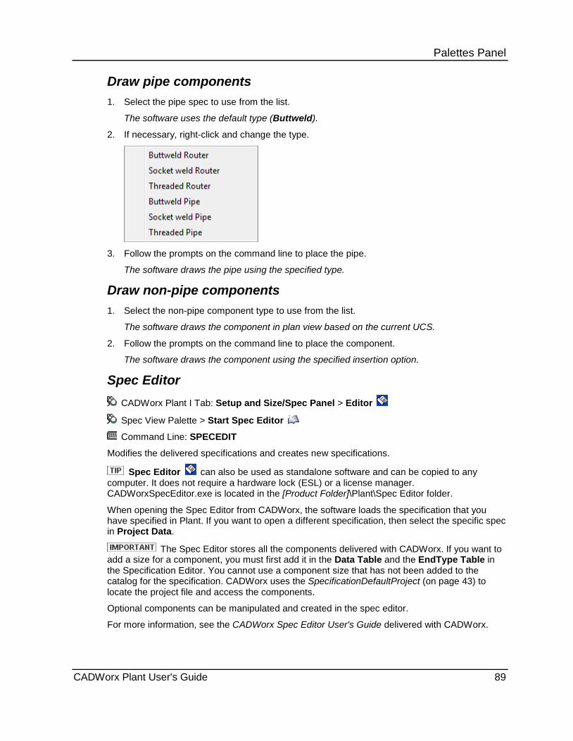
Palettes Panel Draw pipe components 1. Select the pipe spec to use from the list.
The software uses the default type (Buttweld).
2. If necessary, right-click and change the type.
3. Follow the prompts on the command line to place the pipe.
The software draws the pipe using the specified type.
Draw non-pipe components 1. Select the non-pipe component type to use from the list.
The software draws the component in plan view based on the current UCS.
2. Follow the prompts on the command line to place the component.
The software draws the component using the specified insertion option.
Spec Editor CADWorx Plant I Tab: Setup and Size/Spec Panel > Editor
Spec View Palette > Start Spec Editor
Command Line: SPECEDIT
Modifies the delivered specifications and creates new specifications.
Spec Editor can also be used as standalone software and can be copied to any computer. It does not require a hardware lock (ESL) or a license manager. CADWorxSpecEditor.exe is located in the [Product Folder]\Plant\Spec Editor folder.
When opening the Spec Editor from CADWorx, the software loads the specification that you have specified in Plant. If you want to open a different specification, then select the specific spec in Project Data.
The Spec Editor stores all the components delivered with CADWorx. If you want to add a size for a component, you must first add it in the Data Table and the EndType Table in the Specification Editor. You cannot use a component size that has not been added to the catalog for the specification. CADWorx uses the SpecificationDefaultProject (on page 43) to locate the project file and access the components.
Optional components can be manipulated and created in the spec editor.
For more information, see the CADWorx Spec Editor User's Guide delivered with CADWorx.
CADWorx Plant User's Guide 89
Palettes Panel Line Numbering System Dropdown Setup Dialog Box Controls parameters for adding items to the line numbering list that appears with the line numbering system. These values are stored in the DropDownList.TXT file. This file is located in the same folder as the current configuration settings.
Available Categories - Lists the categories for which you can assign dropdown items. Select an item from the list to make it the active category.
Dropdown Values - Lists the assigned dropdown items for the active category.
Add - Adds an item to the Dropdown Values list.
Remove - Removes the selected item from the Dropdown Values list.
Remove All - Removes all of the items from the Dropdown Values list.
Settings Tab (CADWorx Spec View Palette) Controls parameters for customizing the appearance of the CADWorx Spec View palette.
View Options
Show optional components - Displays optional components in the CADWorx Spec View palette. If you select this option, always use the CADWorx Spec View palette to draw components. If you start the component placement from outside of the CADWorx Spec View palette, such as with a command line, SPACE to run last command, or a toolbar, CADWorx uses the default component based on the current size setting. This may not be the same component that was selected in the CADWorx Spec View palette.
Show all components - Displays all components listed in the specification file regardless of the current size set. If you select this option, always use the CADWorx Spec View palette to draw components. If you start the component placement from outside of the CADWorx Spec View palette, such as with a command line, SPACE to run last command, or a toolbar, CADWorx uses the default component based on the current size setting. This may not be the same component that was selected in the CADWorx Spec View palette.
Show socket weld - Displays socket-welded components in the CADWorx Spec View palette.
Show threaded - Displays threaded components in the CADWorx Spec View palette.
Show tag - Displays tags in the CADWorx Spec View palette.
Show long description - Displays long descriptions in the CADWorx Spec View palette.
Show short description - Displays short descriptions in the CADWorx Spec View palette.
Tree Options
View 1 (No tree or categories) - Lists components in numerical order based on the Sort Sequence set for the component in the specification file.
View 2 (One level tree with more categories) - Creates a category for each type of component. For example, butt-welded and socket-welded tees are listed in separate categories.
View 3 (One level tree with less categories) - Creates fewer categories than View 2. For example, all tees are listed in a single category.
View 4 (Two level tree with Spec Editor style view) - Displays a two-level tree that is arranged in the same sequence as the Spec Editor application.
90 CADWorx Plant User's Guide
Palettes Panel Color Options
Main Size component - Specifies the color associated with main size components. Main Size optional component - Specifies the color associated with main size optional components. Reducing Size component - Specifies the color associated with reducing size components. Reducing Size optional component - Specifies the color associated with reducing size optional components. Level 1 category - Specifies the color associated with level 1 category components. Level 2 category - Specifies the color associated with level 2 category components.
Custom Data Tab (CADWorx Spec View Palette) Enables you to overwrite the default value of the custom data in the CADWorx Spec View palette without having to change or update the custom data in the Specification Editor. Field Title - Displays the field title of the custom data. You specify this title when you create custom data in the Specification Editor. You cannot edit this value. You must change this value in the Specification Editor. Description - Displays the description of the custom data. You specify this description when you create custom data in the Specification Editor. You cannot edit this value. You must change this value in the Specification Editor. Default Value - Specifies a new value for the custom data in the drawing. The value you enter here displays in the custom data for your component. You can only change the Default Value in the Custom Data tab here. The change you make does not update the Specification Editor with any new value. Any change to this value overwrites the default value from the Specification Editor. The overwrite you make only applies to this drawing. If you open a new drawing and use the same custom data, the default value of your component pulls the original default value from the Specification Editor. When you draw a component after entering a new Default Value, the new value displays for those components. When using the List option, the Default Value displays the following: *VARIES*. You cannot type in a new value if the Type of custom data is set to List. In that case, you must select and existing item from the list.
Line View Palette CADWorx Plant I tab: Palettes > Line View
Palettes toolbar: Line View
Plant menu: Palettes > Line View
Plant menu: Utility > Line Isolate Palette
Command line: LINEVIEW
The Line View palette isolates components based on their line number, specification, or custom data. It also lets you locate components based on their description information.
Line View does not process any entities on locked layers.
Line Isolate Tab (CADWorx Line View Palette) (on page 92) Find Tab (CADWorx Line View Palette) (on page 93) Line View Isolation Properties Manager (on page 93)
CADWorx Plant User's Guide 91
Palettes Panel
Line Isolate Tab (CADWorx Line View Palette) Controls parameters for isolating components based on their line number, specification, or custom data. You can isolate an entire line number, isolate one line number and include surrounding buildings or equipment, or isolate based on any custom data you have created.
If components have been hidden using the Line Isolate tab, those components are not
listed in the Find tab.
For isolation of multiple field selections in the list of the Line View palette, the following logic is being applied:
OR within the same column.
AND within the same row.
AND between different columns.
Refresh List - Refreshes the line number list in the palette. Use this option if new line numbers do not appear in the list.
Show All Components - Makes all objects in the drawing visible.
Select Line Number by Component - Select a component in the drawing. The software uses the line number of this component to isolate the model.
Isolate Based on Selection - Isolates the selected items in the list.
Invert Isolation - Isolates the reverse of the selected item in the list.
Set Layer Options - Displays the Line View Layer Selection dialog box so that you can include or exclude certain layers when Isolate Type is set to Layer Isolate. For more information, see Layers Dialog Box (on page 113). By default, all layers are visible for line isolate.
Filter Settings Manager - Displays the Line View Isolation Properties Manager which enables you to manage isolations in the drawing. For more information, see Line View Isolation Properties Manager (on page 93).
Help - Displays on-line help.
Right-clicking the line number list displays the Isolate Selected Items, Invert Isolate Selected Items, Show All Components, Set Layer Options, Refresh List, Sort Ascending, and Sort Descending options.
Isolate Type
Full - Displays the selected CADWorx components, and hides all non-CADWorx components such as buildings, equipment, and dimensions.
Partial - Displays the selected CADWorx components and all non-CADWorx components.
Layer - Displays the selected CADWorx components and hides all non-CADWorx components based on the layer setup.
Filter - Enter a wildcard filter to limit the items available in the list. The filter is case sensitive. For wildcard character details, see Select Item Dialog Box (on page 166).
92 CADWorx Plant User's Guide

Palettes Panel
Find Tab (CADWorx Line View Palette) Controls parameters for locating components based on their description information.
Click the edit boxes to refresh the list of components. Type in the boxes to dynamically filter the list of available components.
If components are hidden using the Line Isolate tab, those components are not listed in the Find tab.
Tag - Type tag text to refine the search. If you select an item from the list, the associated text displays.
Code - Type code text to refine the search. If you select an item from the list, the associated text displays.
Line number - Type line number text to refine the search. If you select an item from the list, the associated text displays.
Short annotation - Type short annotation text to refine the search. If you select an item from the list, the associated text displays.
Long annotation -- Type long annotation text to refine the search. If you select an item from the list, the associated text displays.
Id Count - Type ID count text to refine the search. If you select an item from the list, the associated text displays.
Right-Click Menu
Zoom - Zooms the current model space view to the component. Double clicking in the list of components also zooms to the component. Zoom does not work with XREFs that have been inserted into the base drawing with a rotation.
CEdit - Displays the appropriate Component Edit dialog box. CEdit on an XREF component does not allow any changes to the component descriptions.
Refresh - Refreshes the list in the dialog box. Use this option if new components do not appear in the list.
Line View Isolation Properties Manager Enables you to manage isolations in a drawing.
Isolation Setting File - Specifies the selected isolation file. Isolation setting files are created using New, and then saved using Save As.
You can set a default isolation setting file by selecting a created file through the LineViewIsolationSettingsFile variable.
Load - Enables you to load an isolation setting file.
Selected Items - Specifies the items from the Live View palette and enables you to select them individually for isolation. These selections can be saved.
Isolation Setting List - Specifies the name of the isolation setting you created using New.
New - Enables you to create a new Isolation Setting to manage an isolation group.
Click New, type a name in the New Name dialog box, and then click OK.
Delete - Enables you to delete an Isolation Setting.
CADWorx Plant User's Guide 93
Palettes Panel Rename - Enables you to rename an Isolation Setting.
Select a List Name, click Rename.
The Rename dialog box displays.
Type a new name, and then click OK.
OK - Enables you to isolate a selected item from Selected Items.
Select an item, and then click OK.
Save - Saves the new Isolation Setting you created for the management of this isolation.
Save As - Enables you to save an isolation setting file.
Select / deselect all - Enables you to select or clear all items in Selected Items.
Support Modeler Palette CADWorx Plant I tab: Palettes > Pipe Support Modeler
Palettes toolbar: Pipe Support Modeler
Plant menu: Palettes > Pipe Support Modeler
Command line: PIPESUPPORTVIEW
Inserts pipe and elbow support components.
You must have both the Pipe Support Assembly in a project and the PipeSupport category in a catalog for the pipe supports to be inserted. For more information, see Pipe Support Assembly and PipeSupport in the CADWorx Spec Editor User's Guide.
Start Spec Editor - Displays the Spec Editor software. For more information, see Spec Editor (on page 89) or the CADWorx Spec Editor User's Guide.
Replace Pipe Support - Enables you to replace a pipe support. For more options and information on replacing the pipe support, see Edit Pipe Support Features (on page 98).
Regenerate Pipe Support - Regenerates the pipe support from the updated data when a change is made to the data of a pipe support already contained in the drawing. For more information, see Edit Pipe Support Features (on page 98).
View Settings - Displays the View Settings dialog box.
Reload *.prj File - Refreshes the changes made to the open .prj file in the Specification Editor.
Help - Displays the help file.
Main Size - Specifies the main size for the pipe support components.
Assembly - Specifies the assembly file associated with the project.
The directory location for the project containing the pipe support data is listed below Main Size and Assembly. The components for the pipe supports are listed and can be selected from the box below the directory.
94 CADWorx Plant User's Guide
Palettes Panel Insert Options Multiple - Inserts multiple supports onto the pipe. You specify the start point, end point, and spacing between the supports. This option is only available for pipe supports.
Detect Steel - Detects CADWorx Steel components to set the correct size for the beam clamp if the beam clamp is used as the last component in the pipe support assembly.
Repeat Insert - Repeats the insert command for pipe type supports.
Type INSERTSUPPORT on the command line to insert the last selected pipe support or the start procedure of the last selected component.
Right-click menu for INSERTSUPPORT poinT distance - Enables you to specify a point on the pipe or component to move the selected component.
Component distance - Displays the distance from the selected component to the selected piping or component. The distance measured to a specifically selected component can be changed by using Point.
Point - Enables you to change the distance from the selected component to another component on the same linear pipe.
Pipe end point distance - Displays the distance measurement from the selected component to the end of the pipe. Repeating the command changes the direction of the measurement to the opposite end of the piping, where it connects to the next component.
View Settings Dialog Box View 1 - Sets the software to display each pipe support.
View 2 - Sets the software to display the pipe supports based on type.
Pipe Support Color - Specifies the color of the piping support. To change the color, click the color to open the Color dialog box, select a color, and then click OK.
Tee Support Color - Specifies the color of the tee support. To change the color, click the color to open the Color dialog box, select a color, and then click OK.
Elbow Support Color - Specifies the color of the elbow support. To change the color, click the color to open the Color dialog box, select a color, and then click OK.
Pipe Support Data Dialog Box Enables you to enter the length of certain parts and select a different size of a specific component on a pipe support when available.
Nominal Size - Specifies the nominal size for the pipe support. This size is based off the Main Size selection when a specification is selected.
Name - Specifies the name of the pipe support.
Length - Specifies the length of the pipe support. This can be changed.
Data Table - Specifies the values from the data table selected for that pipe support. Click the ellipsis to select a different size for the part from the list. This ellipsis is only available for certain parts. The list contains information pertaining to the specific pipe support part, such as Nominal Size, Pipe OD, Thickness, Length, Width, and Weight.
CADWorx Plant User's Guide 95
Palettes Panel
Insert a pipe support 1. Set a specification. For more information, see Set Specification & Size Dialog Box (on page
47).
The pipe support list populates with the pipe support information from the specification.
2. If needed, change the size of a pipe support using Main Size.
3. Select an Assembly, or use the default.
4. Select a pipe support from the list.
5. Select the pipe from the model.
6. Select the location on the pipe to insert the support.
OR
The Pipe Support Data dialog box displays. This dialog box only displays when optional items are available.
Specify the data for the pipe support, and then click OK.
7. Specify an insertion point and rotation around the pipe.
The software places the pipe support in the model.
Insert an elbow support When inserting an elbow support, the following options are available for a new start point:
A - Places the support at the A point in the drawing. A could be either the Top of Pipe or the Bottom of Pipe. B - Places the support at the B point in the drawing. B could be either the Top of Pipe or the Bottom of Pipe. Corner (C) - Places the support at the corner of the elbow. miDpoint (D) - Places the support at the midpoint of the elbow. E - Places the support at the E point in the drawing. E could be either the Top of Pipe or the Bottom of Pipe. F - Places the support at the F point in the drawing. F could be either the Top of Pipe or the Bottom of Pipe. 1. Set a specification. For more information, see Set Specification & Size Dialog Box (on page
47). The pipe support list populates with the pipe support information from the specification.
2. If needed, change the size of a pipe support using Main Size. 3. Select an Assembly or use the default. 4. Select an elbow support from the list. 5. Select the elbow from the model. 6. Specify the end point, the rotation around the pipe, and the length of the support.
OR The Pipe Support Data dialog box displays. This dialog box only displays when optional items are available. Specify the data for the pipe support, and then click OK.
7. Specify an insertion point and rotation around the pipe. The software places the pipe support in the model.
96 CADWorx Plant User's Guide
Palettes Panel
Insert a tee support 1. Set a specification. For more information, see Set Specification & Size Dialog Box (on page
47).
The pipe support list populates with the pipe support information from the specification.
2. If needed, change the size of a pipe support using Main Size.
3. Select an Assembly, or use the default.
The assembly must contain a tee support. To add a new tee support, see Add Support Component in the CADWorx Spec Editors User's Guide.
4. Select a tee support from the list.
5. Select the tee in the model.
The tee support displays.
6. Orient the support as need.
OR
The Pipe Support Data dialog box displays. This dialog box only displays when additional input is required.
7. Specify the length for the pipe support, change Data Table selection if needed, and then click OK.
The software places the pipe support in the model.
Insert multiple pipe supports 1. Set a specification. For more information, see Set Specification & Size Dialog Box (on page
47).
The pipe support list populates with the pipe support information from the specification.
2. If needed, change the size of a pipe support using Main Size.
3. Select an Assembly or use the default.
4. Under Insert Options, select the Multiple check box.
5. Select a pipe support from the list.
6. Specify a start point on the pipe.
7. Specify an end point on the pipe.
OR
The Pipe Support Data dialog box displays. This dialog box only displays when optional items are available.
Specify the data, and then click OK.
8. Specify the distance between each pipe support by entering the value on the command line, and then press ENTER.
9. Specify a rotation around the pipe and the length of the pipe support.
The software places the pipe supports in the model.
CADWorx Plant User's Guide 97
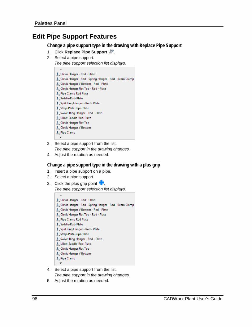
Palettes Panel
Edit Pipe Support Features Change a pipe support type in the drawing with Replace Pipe Support 1. Click Replace Pipe Support . 2. Select a pipe support.
The pipe support selection list displays.
3. Select a pipe support from the list.
The pipe support in the drawing changes. 4. Adjust the rotation as needed.
Change a pipe support type in the drawing with a plus grip 1. Insert a pipe support on a pipe. 2. Select a pipe support. 3. Click the plus grip point .
The pipe support selection list displays.
4. Select a pipe support from the list.
The pipe support in the drawing changes. 5. Adjust the rotation as needed.
98 CADWorx Plant User's Guide
Palettes Panel Regenerate a pipe support in the drawing 1. Click Regenerate Pipe Support .
2. Select the pipe support, and then press ENTER.
The pipe support in the drawing updates.
Move a pipe with a pipe support attached. 1. Select the pipe you want to adjust.
The grip points display.
2. Select a grip point .
3. Move the piping as needed.
The pipe support adjusts with the movement of the piping.
The grip point at the end of the pipe support enables you to rotate and change the length
of the rod of the pipe support.
The grip point at the top of the pipe support where it connects to the piping, enables you to move the pipe support along the pipe. The pipe support cannot move around corners, such as elbows or tees.
Change the size of a pipe inside a pipe support 1. Insert a pipe support on a pipe.
2. Click Change Size . Alternatively, type CHANGESIZE on the command line, and press ENTER.
3. Press ENTER for automatic.
4. Select a component.
5. Select a size from the list that displays.
If a size is not available in the catalog for a component, the process stops, forcing you to start over.
6. Select a component to keep its position, or press ENTER to finish.
If prompted select, the BOP, TOP, or Current after selecting the piping to keep the position.
The software continues to prompt you for selection of a component until you press ENTER to finish.
The entire drawing changes its size.
CADWorx Plant User's Guide 99
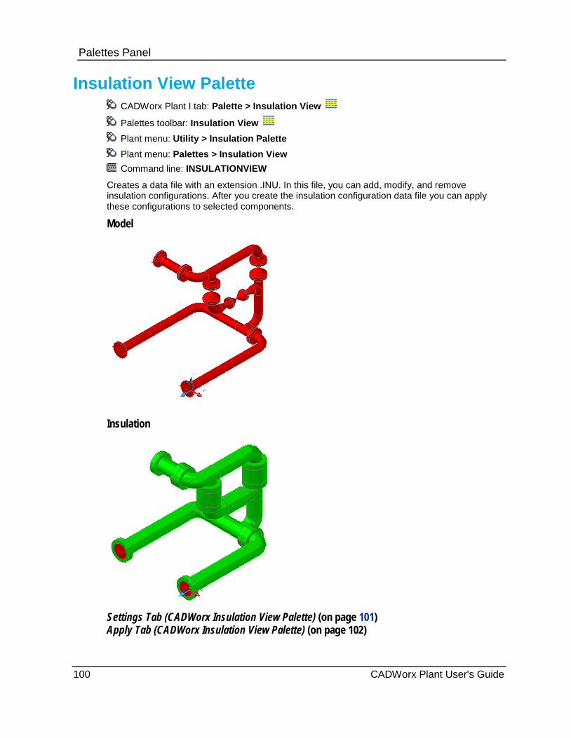
Palettes Panel
Insulation View Palette CADWorx Plant I tab: Palette > Insulation View
Palettes toolbar: Insulation View
Plant menu: Utility > Insulation Palette
Plant menu: Palettes > Insulation View Command line: INSULATIONVIEW
Creates a data file with an extension .INU. In this file, you can add, modify, and remove insulation configurations. After you create the insulation configuration data file you can apply these configurations to selected components.
Model
Insulation
Settings Tab (CADWorx Insulation View Palette) (on page 101) Apply Tab (CADWorx Insulation View Palette) (on page 102)
100 CADWorx Plant User's Guide

Palettes Panel
Settings Tab (CADWorx Insulation View Palette) Controls parameters for creating a data file with an .INU extension. In this file, you can add, modify and remove insulation configurations that can be applied to CADWorx components.
Save - Saves the data in the Configuration Setup grid to the configuration file.
Save As - Displays the Save As Insulation Data dialog box to save the current data in the Configuration Setup grid to a new file.
Open - Displays the Open Insulation Data dialog box to load an insulation data file. The data contained in that file is displayed in the Configuration Setup grid and listed individually in the drop down categories. Configuration Setup Add to drawing - Saves the selected grid rows to the current AutoCAD drawing. If similar data already exists in the current drawing, it is not overwritten. All configurations that have been added, appear in the Apply tab of the palette. Options - Displays the Insulation Options dialog box. For more information, see Insulation Options Dialog Box below. Configuration Setup - Grid - Displays the content of the insulation data file in grid form. Thickness - Specifies the actual insulation thickness value. Type a numeric value greater than zero. You can also select an existing value. This parameter is required to create an insulation configuration. In Imperial units (Imperial pipe size / Imperial dimensions), type a value in inches. In mixed metric units (Imperial pipe size / metric dimensions), type a value in inches or
millimeters based on the setting from the Insulation Options dialog box. If you type inch values, the software automatically converts to millimeters when the insulation solid is created in the model. If you type a millimeter value, no conversion is done.
In metric units (metric pipe size / metric dimensions), type a value in millimeters. Density - Specifies the insulation density value. Type numeric values greater than zero. You can also select an existing value. The density is used to calculate the insulation weight by multiplying it with the insulation volume. This parameter is required to create an insulation configuration. In Imperial units (Imperial pipe size / Imperial dimensions), this value has units of lb / in3. In mixed metric (Imperial pipe size / metric dimensions) the value has units of g / cm3. In metric (metric pipe size / metric dimensions), the value has units of g / cm3. Mastic - Specifies the mastic description. This is an optional value. Heat Tracing - Specifies the heat tracing description. This is an optional value. Insulation - Specifies the insulation description. This is an optional value. Jacketing - Specifies the jacketing description. This is an optional value. User - Specifies the user description. This is an optional value. Add - Adds the current values from the boxes to the grid. If similar data exists, the value is not added to the grid. Modify - Modifies the currently selected row in the grid using the values currently shown in the boxes. Each box corresponds to a column in the grid. Remove - Deletes the currently selected row in the grid.
Add, Modify, and Remove only change the data currently displayed in the grid. The data in the insulation file is not updated until you click Save or Save As.
CADWorx Plant User's Guide 101

Palettes Panel Insulation Options Dialog Box Controls parameters for insulation options.
Insulation
Append "_I" to layer name - Adds the characters _I to the layer name to create the insulation layer name. For example, if the solid is on layer 1"-150-CWS, the insulation solid is on 1"-150-CWL_l. The insulation solid is grouped with the component solid and center line.
New Layer Name - Indicates that the software creates a new layer.
Name - Specifies the layer name for the insulation solids.
Color - Displays the standard AutoCAD color selection dialog box. Select the default layer color for the insulation.
Graphics
Show Graphics for Gasket - Indicates whether gasket insulation graphics display. This works only for enhanced mode.
Show Graphics for Weld gap - Indicates whether weld gap insulation graphics display. This works only for enhanced mode.
Show Graphics for User Shapes - Indicates whether user shape insulation graphics display.
Metric/Inch Units system
Millimeter - Indicates that you can enter thicknesses in millimeters in mixed metric units (Imperial pipe size / metric dimensions) situations.
Inch - Indicates that you can enter thicknesses in inches in mixed metric units (Imperial pipe size / metric dimensions) situations.
Apply Tab (CADWorx Insulation View Palette) Controls parameters for applying configurations to CADWorx components.
For most CADWorx components, insulation is approximated with the use of single or multiple AutoCAD cylindrical components.
Available Configuration - Displays the currently saved insulation configurations in the current AutoCAD drawing.
Remove - Removes the highlighted row in the grid from the current drawing.
Select Mode
Select on screen - Indicates that you will select components in the drawing window.
Line number - Indicates that you will select components by line numbers.
Insulation Mode
Data/Graphics - Adds both the insulation graphic and data.
Data Only - Adds only the insulation data and no graphics.
Insulation
Add - Adds the insulation currently selected in the Available Configuration grid to components in the drawings. You are prompted to select CADWorx components. If any of the selected components are already insulated, this action is skipped.
102 CADWorx Plant User's Guide
Palettes Panel Modify - Modifies existing insulation graphics and data.
Remove - Removes existing insulations graphics and data.
Refresh - Generates the graphics from the insulation data stored in the component's centerline. Use this option if insulation graphics were deleted or lost.
Graphics
Add - Adds insulation graphics to components that have had their graphics removed. The data previously stored in the components is used to generate the graphics.
Remove - Removes the graphics from the selected components. The insulation data remains. These components do not show the insulation solid even if you later click Refresh.
Visibility
Isolate - Isolates insulation graphics by either selecting components on screen or by selecting line numbers from the list.
Hide/Show - Hides or shows the insulation graphics by selecting components on screen or by selecting line numbers from the list.
Show All - Shows all objects that have been previously hidden in the current drawing.
Report - Creates a complete report, in HTML format, about all of the insulation components in the model. The report is itemized by the different types of insulation data and calculates the total weight, volume, and length.
Filter - Filters the list of line numbers using wild cards. For example, type *25-1B* to limit the line number list to line numbers with 25-1B as part of the name. The text filter occurs regardless of where the text is in the line number name.
Edit - Displays the Insulation Global Edit <number> Objects dialog box so that you can edit the insulation data for all components having the selected insulation configuration.
Right-Click Menu
In Line Number selection mode, a right-click menu is available with additional options. The right-click menu changes what displays in the edit box.
Select All / Clear All - Selects or clears all line numbers in the list.
List Insulated Line Numbers - Lists only insulated line numbers.
List Un-Insulated Line Numbers - Lists only uninsulated line numbers.
List Data Only Line Numbers - Lists line numbers that have insulation data but no insulation graphics.
List Un-Insulated Components - Lists only uninsulated components.
List All - Refreshes the list.
Modify - Replaces the selected insulation data with the highlighted insulation in the Available Configuration grid. This change applies to all components in the selected line number.
Remove - Removes the insulation from all components in the selected line number.
CADWorx Plant User's Guide 103
Palettes Panel Insulation Global Edit <number> Objects Dialog Box Controls parameters for editing the insulation data on multiple objects. This dialog box applies the settings to all of the selected objects.
Thickness - Displays the insulation thickness value. You cannot edit this value.
Density - Specifies the insulation density value. Type numeric values greater than zero. You can also select an existing value. The density is used to calculate the insulation weight by multiplying it with the insulation volume. This parameter is required to create an insulation configuration.
In Imperial units (Imperial pipe size / Imperial dimensions), this value has units of lb / in3.
In mixed metric (Imperial pipe size / metric dimensions) the value has units of g / cm3.
In metric (metric pipe size / metric dimensions), the value has units of g / cm3.
Mastic - Specifies the mastic description. This is an optional value.
Heat Tracing - Specifies the heat tracing description. This is an optional value.
Insulation - Specifies the insulation description. This is an optional value.
Jacketing - Specifies the jacketing description. This is an optional value.
User - Specifies the user description. This is an optional value.
Discontinuity View Palette CADWorx Plant I tab: Palette > Discontinuity View
Palettes toolbar: Discontinuity View
Plant menu: Palettes > Discontinuity View
Command line: DISCONTINUITYVIEW
Checks for different types of modeling issues, such as disconnected, un-connected, overlapped, and not on line.
Refresh - Refreshes the data in the grid.
Show All Types - Displays all issues in the grid.
Show Disconnected Only - Displays only disconnected and un-connected issues in the grid.
Show Not On Line Only - Displays only not-on-line issues in the grid.
Show Overlap Only - Displays only overlap issues in the grid.
Tolerance Settings - Displays the tolerance settings.
Color Settings - Displays the color and Auto Refresh settings.
Remove Selected Overlaps - Deletes the selected overlaps from the model .DWG file.
Export to File - Exports all data from the palette to a Microsoft Excel (*.CSV) file
Help - Displays the help file.
104 CADWorx Plant User's Guide
Palettes Panel Tolerance Min - Specifies the minimum connection tolerance. Two components that are separated by a distance greater than the minimum tolerance, but less than the maximum tolerance are considered disconnected.
Tolerance Max - Specifies the maximum connection tolerance. Two components that are separated by a distance greater than the maximum tolerance are considered un-connected.
Color Arrow - Specifies the color for arrows.
Color Text - Specifies the color for text.
Auto Refresh - Indicates whether the software automatically updates the grid when you open the drawing.
# - Displays a number from the palette that coincides with the highlighted number in the drawing. The arrow and text color setting is used for the graphics drawn in the model.
Line Number - Displays the line number of the component.
Type - Displays the discontinuity type for the component.
Disconnected - Displays components that are not connected within the minimum tolerance.
Un-connected - Displays components that are not connected with in the maximum tolerance.
Overlap - Displays components that are duplicated at the same location. The number in parenthesis (n) is the number of overlapping components at this location.
Not on line - Displays components that are not connected to the pipe centerline (typically OLET type components).
Gap - Displays the distance between the two components. This value is 0.0 for overlapping components.
Long Description - Displays the long description of the component.
Category - Displays the category of the component.
Component Type - Displays the command named used to draw the component.
(X,Y,Z) - Displays the global X-, Y-, Z-coordinates of the component center point.
Pressing CTRL or SHIFT while left-clicking lets you select multiple items from the list.
Left-click to zoom in to the location of the issue.
CADWorx Plant User's Guide 105
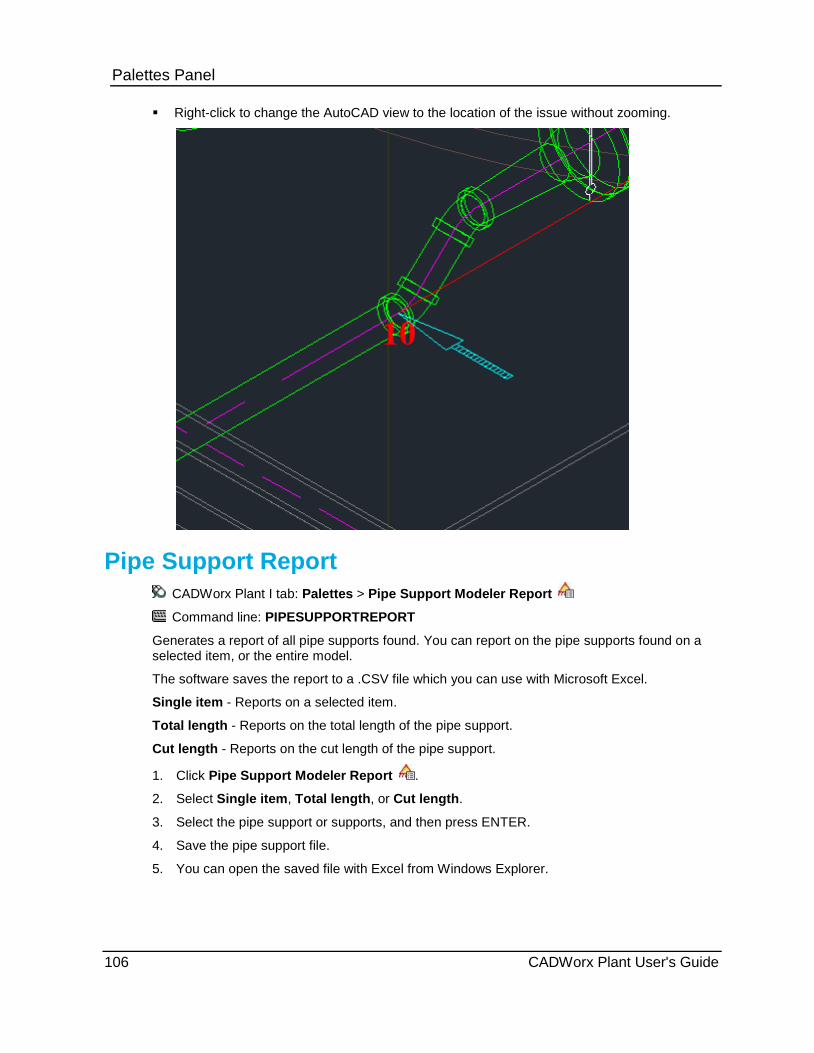
Palettes Panel Right-click to change the AutoCAD view to the location of the issue without zooming.
Pipe Support Report CADWorx Plant I tab: Palettes > Pipe Support Modeler Report
Command line: PIPESUPPORTREPORT
Generates a report of all pipe supports found. You can report on the pipe supports found on a selected item, or the entire model.
The software saves the report to a .CSV file which you can use with Microsoft Excel.
Single item - Reports on a selected item.
Total length - Reports on the total length of the pipe support.
Cut length - Reports on the cut length of the pipe support.
1. Click Pipe Support Modeler Report .
2. Select Single item, Total length, or Cut length.
3. Select the pipe support or supports, and then press ENTER.
4. Save the pipe support file.
5. You can open the saved file with Excel from Windows Explorer.
106 CADWorx Plant User's Guide

Palettes Panel
P&ID View Palette CADWorx Plant I tab: Palette > PID View
Palettes toolbar: P&ID View
Plant menu: Palettes > P&ID View
Command line: PIDVIEW
Links data between the Plant and P&ID table in a project database.
You must set up the following items to use this palette:
1. Create a CADWorx P&ID project that uses the P&ID live database system.
2. Create a CADWorx Plant project that uses the Plant live database system.
3. With Microsoft Access, you must write database tables used by Plant and P&ID to the same Access file. With SQL Server and Oracle, you must write database tables used by Plant and P&ID to the same database.
4. Create associations between in-line components and the main process line in the P&ID drawings with the Combine Process command. For more information, see Combine Process in the CADWorx P&ID User's Guide.
Matched Tab (CADWorx P&ID View Palette) (on page 107)
Unmatched Tab (CADWorx P&ID View Palette) (on page 110)
Matched Tab (CADWorx P&ID View Palette) Controls parameters for linking matched data between the Plant and P&ID table in a project database.
Select Configuration File
The current configuration file (Project.CFG) displays.
Browse - Select a different Project.CFG file
Options - Displays available options.
Available Line Numbers - Displays line numbers that are in both the P&ID database and the Plant database.
Select - Specifies a component in the current Plant model drawing. The software sets the line number of this component to the current line number for P&ID View.
Component Type - Displays the component tables from the P&ID database.
Link - Links or unlinks P&ID and Plant components.
Help - Displays on-line help.
P&ID Data
P&ID ID_Count - Lists the P&ID ID_COUNT from the P&ID database.
Line Number - Lists the line number for the P&ID component.
Tag - Lists the tag for the P&ID component.
CADWorx Plant User's Guide 107

Palettes Panel Size - Lists the size for the P&ID component.
Spec- Lists the spec for the P&ID component.
Drawing - Lists the drawing for the P&ID component.
Right-Click Menu
Insert in model - Reads the size, spec, and component type from the P&ID database and inserts the component into the Plant model.
View P&ID drawing - Displays a preview of the P&ID drawing.
To zoom inside the viewer, use the two arrow buttons on the left side of the dialog box. Zooming inside the viewer can also be done by holding down the left mouse button while rotating the mouse scroll wheel. The viewer dialog box closes when you switch between drawings in the same session of AutoCAD. The dialog box must be started with every new AutoCAD session.
Left-click an item to update the P&ID drawing viewer dialog box if it is active.
Double-click an item to run the Insert in model command.
Refresh - Refreshes the P&ID Data and Plant Data lists.
Options - Displays the Options dialog box so that you can set the colors of the items displayed in the P&ID and Plant data.
Plant Data
P&ID ID_Count - Displays the ID_COUNT of the P&ID component if a link between the P&ID component and the Plant component is made. The Plant database (PIPE table) saves the P&ID ID_COUNT in the RESERVE_10 column.
Line Number - Displays the line number of the plant component.
Tag - Displays the tag of the plant component.
Size - Displays the size of the plant component.
108 CADWorx Plant User's Guide
Palettes Panel Spec - Displays the spec associated with the plant component.
Drawing - Displays the drawing associated with the plant component.
Description - Displays the description of the plant component.
Right-Click Menu
CEdit - Displays the appropriate Component Edit dialog box.
Zoom - Zooms and highlight the component in the model.
List data from all drawings - Lists plant data from all drawings that have the line number.
List data from current drawing - Lists plant data from the open drawing.
Refresh - Refreshes the P&ID Data and Plant Data lists.
Options Dialog Box Controls parameters for setting the colors of the items displayed in the P&ID Data and Plant Data lists on the P&ID View palette.
Color Options
Unlinked components - Specifies the color for unlinked components.
Linked components - Specifies the color for linked components.
Highlight - Specifies the highlight color.
Auto load last Project.cfg file - Indicates whether the last-used configuration file is automatically loaded.
What do you want to do? Link components (on page 109)
Unlink components (on page 109)
Link components 1. Select the check box next to an item in the P&ID Data list and an item in the Plant Data list.
2. Click Link.
The P&ID ID_Count value in the Plant Data list updates.
Vales, reducers, and nozzles can be linked. Instrument components cannot be linked.
Unlink components 1. Select two linked components.
Link changes to Unlink.
2. Click Unlink.
The software removes the link between the two components.
CADWorx Plant User's Guide 109
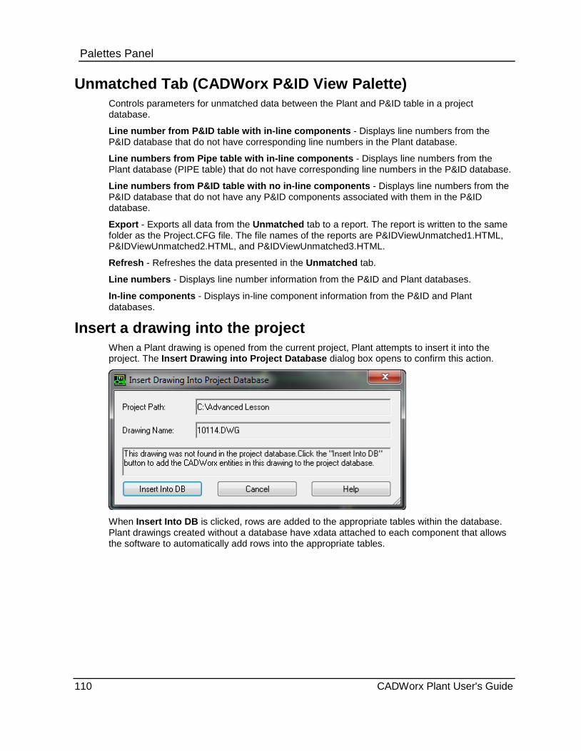
Palettes Panel
Unmatched Tab (CADWorx P&ID View Palette) Controls parameters for unmatched data between the Plant and P&ID table in a project database.
Line number from P&ID table with in-line components - Displays line numbers from the P&ID database that do not have corresponding line numbers in the Plant database.
Line numbers from Pipe table with in-line components - Displays line numbers from the Plant database (PIPE table) that do not have corresponding line numbers in the P&ID database.
Line numbers from P&ID table with no in-line components - Displays line numbers from the P&ID database that do not have any P&ID components associated with them in the P&ID database.
Export - Exports all data from the Unmatched tab to a report. The report is written to the same folder as the Project.CFG file. The file names of the reports are P&IDViewUnmatched1.HTML, P&IDViewUnmatched2.HTML, and P&IDViewUnmatched3.HTML.
Refresh - Refreshes the data presented in the Unmatched tab.
Line numbers - Displays line number information from the P&ID and Plant databases.
In-line components - Displays in-line component information from the P&ID and Plant databases.
Insert a drawing into the project When a Plant drawing is opened from the current project, Plant attempts to insert it into the project. The Insert Drawing into Project Database dialog box opens to confirm this action.
When Insert Into DB is clicked, rows are added to the appropriate tables within the database. Plant drawings created without a database have xdata attached to each component that allows the software to automatically add rows into the appropriate tables.
110 CADWorx Plant User's Guide
Palettes Panel
Clash View Palette CADWorx Plant I tab: Palette > Clash View
Palettes toolbar: Clash View
Plant menu: Palettes > Clash View
Plant menu: Utility > Clash
Command line: CLASH or CLASHVIEW
Runs interactive clash detection on AutoCAD 3D solids in the current drawing and any attached XREF drawings.
Settings
Clash On - Turns the clash system on.
Clash Off - Turns the clash system off.
Show Clashes - Displays clash entities that exist in the model.
Options - Displays the Options dialog box. For more information, see Options Dialog Box (on page 112).
Layers - Displays the Layers dialog box. For more information, see Layers Dialog Box (on page 113).
Refresh - Updates the clash list.
Export - Writes the clash list to a text file. The file is exported to the same folder as the model drawing file. The name of the file is the drawing name with _Clash.TXT appended.
Display by Status
New - Displays new clashes in the list.
Active - Displays active clashes in the list.
Resolved - Displays resolved clashes in the list.
Approved - Displays approved clashes in the list.
All - Displays all clashes in the list.
Clash List
# - Displays the number assigned to each clash.
Component 1 - Displays the CADWorx data for the first component.
Component 2 - Displays the CADWorx data for the second component.
Status - Displays the clash status.
Type - Indicates whether the clash was from a CADWorx Insulation View-created component.
You can set the color of the grid items using the Options dialog box. For more information,
see Options Dialog Box (on page 112).
Left-clicking an item in the list generates the clash entity in the model and zooms to the clash.
CADWorx Plant User's Guide 111

Palettes Panel Right-Click Menu
Clash Status New - Changes the status of a clash to New. Clash Status Active - Changes the status of a clash to Active. Clash Status Resolved - Changes the status of a clash to Resolved. Clash Status Approved - Changes the status of a clash to Approved. Clash Zoom To - Zooms to the clash point. Clash Viewer - Displays a dialog box with the two clashing components. Clash Isolate Selected - Isolates the selected clash. Clash Isolate All - Creates clash entities for all clashes, and isolates them. To remove all clash entities from the model, run the command CLASHDELETEALLOBJECTS. Clash Show All - Shows all components in the drawing.
Options Dialog Box Controls parameters for setting options on clash objects.
Start up - Indicates whether clash detection runs on drawing start up. On - Clash detection is always on for every drawing. Off - Clash detection is off for every drawing.
Display Prompt - The software prompt you every time a drawing opens.
On clash detection - Indicates what happens when a clash is detected.
Do Not Report - The software does not notify you if a clash is detected. Show Tray Notification - The software notifies you through the tray bubble notification that
a clash has occurred. Show Palette - The software displays the Clash View palette every time a clash is
detected.
Ignore connected steel - Indicates whether the clash detection system checks for connecting steel members. If this option is selected, steel members that are touching each other are ignored.
Detect clashes within blocks - Indicates whether the software detects clashes inside blocks. If this option is selected, the system detects clashes within any blocks in the current drawing.
Synchronize clashes from XREFs - Indicates whether the software checks for clash data inside external reference drawings and updates the master drawing data for that clash. Only New clashes in the master drawing which are from an XREF drawing have the status updated to match the status that is saved in the XREF drawing.
Synchronize layers from XREFs - Indicates whether the system checks for clash layer data inside externally reference drawings and updates the master drawing clash layer data to match. If a layer in an XREF is excluded from clash detection, the XREF layer is also excluded in the master drawing.
Ignore insulation clashes - The system ignores all clashes generated from components created with the CADWorx Insulation View palette.
Connectivity tolerance - Specifies the tolerance for checking component connectivity. If two components are connected, a clash is not reported, even if the actual solids intersect.
Clash zoom factor - Specifies the zoom factor used during clash.
Color Options - Specifies the color of the clash entity and the color of the list.
112 CADWorx Plant User's Guide
Palettes Panel
Layers Dialog Box Controls parameters for including or excluding certain layers from clash detection. By default, all layers are considered for clash detection. XREF layers are also displayed.
Layers - Displays the available layers. Select the check box next to the layer name to include that layer in clash detection.
Select all - Selects all of the layers in the list.
Clear all - Clears the selection of all of the layers in the list.
Assembly View Palette CADWorx Plant I tab: Palette > Assembly View
Palettes toolbar: Assembly View
Plant menu: Palettes > Assembly View
Command Line: ASSEMBLYVIEW
Creates assemblies for placement in a model. The Assembly Manager has four options: create, edit, delete, and insert.
Command Name Command Line
Create Assembly - Creates a new assembly. For more information, see Create an assembly (on page 114).
MAKEASSEMBLY
Edit Assembly Selected - Edits the selected assembly. For more information, see Edit an assembly (on page 114).
Delete Assembly Selected - Deletes the selected assembly. For more information, see Delete an assembly from the Assembly Manager (on page 115).
Insert Assembly Selected - Inserts the selected assembly into the model. For more information, see Insert an assembly into the drawing (on page 115).
INSERTASSEMBLY
Help - Opens the help file.
Edit Assembly Paths - Edits the path folder location of the assembly. For more information, see Edit an assembly path (on page 115).
ASSEMBLYEDITPATHS
Project File - Specifies the project file selected for the assembly.
Global File - Specifies the global assembly file associated with the assembly. Click Browse to change the global assembly file.
CADWorx Plant User's Guide 113

Palettes Panel Right- Click Menu Insert Assembly - Inserts an assembly.
View Assembly - Opens the Assembly Viewer and displays the assembly. The assembly can be zoomed and rotated for a 360-degree view.
a. Wireframe - Displays the model in wireframe view.
b. Hidden - Displays the model in hidden view.
c. Shaded - Displays the model with shaded view.
Modify Assembly - Enables you to edit an assembly.
New - Creates a new assembly.
Rename - Renames an assembly.
Delete - Deletes an assembly.
Copy - Copies an assembly.
Paste - Pastes an assembly.
Reload Global File - Reloads the global assembly file.
Edit File Paths - Edits the path folder location of the assembly.
You can close the Assembly Manager at anytime by typing ASSEMBLYCLOSE on the command line.
Create an assembly 1. Click Assembly View . Alternatively, type ASSEMBLYVIEW on the command line, and
press ENTER.
2. Click Create Assembly .
3. Select all the components necessary for the assembly, and press ENTER
4. Pick a point where you want to connect.
5. Type a name on the command line, and press ENTER.
The assembly appears in the Assembly Manager.
Edit an assembly 1. Click Assembly View . Alternatively, type ASSEMBLYVIEW on the command line, and
press ENTER.
2. Click Edit Assembly Selected .
3. Make the changes to the drawing as needed.
4. Click Close Assembly Editor.
5. Click Yes to save the changes.
To close the Assembly Editor without saving any changes, click No.
The change is saved.
114 CADWorx Plant User's Guide
Palettes Panel
Delete an assembly from the Assembly Manager 1. Click Assembly View . Alternatively, type ASSEMBLYVIEW on the command line, and
press ENTER.
2. Select an assembly for deletion.
3. Click Delete Assembly Selected .
4. Click OK to delete.
If you do not want to delete the object, click Cancel.
The assembly disappears from the Assembly Manager.
Insert an assembly into the drawing 1. Click Assembly View . Alternatively, type ASSEMBLYVIEW on the command line, and
press ENTER.
2. Select an assembly from the Assemblies box.
3. Click Insert Assembly Selected .
4. Select a component to connect to.
5. Select a direction.
The assembly appears in the drawing.
If an assembly is built with a reducer and then attached to a component of a larger size you are prompted to change the size of the reducer. The assembly usually takes on the size and the specification of the component to which it is attached.
Edit an assembly path 1. Click Assembly View . Alternatively, type ASSEMBLYVIEW on the command line, and
then press ENTER.
2. Type ASSEMBLYEDITPATHS on the command line, and then press ENTER.
3. Select Project and then the name of the assembly from the popup.
OR
Select Global Assembly and then the name of the assembly from the popup.
4. Enter the subdirectory for the user shape path, and then press ENTER.
OR
Type B on the command line for the user shape path, press ENTER to open the Browse for Folder window, select the new folder location, click OK, and then press ENTER.
5. Enter the subdirectory for the Topworks path, and then press ENTER.
OR
Type B on the command line for the Topworks path, press ENTER to open the Browse for Folder window, select the new folder location, click OK, and then press ENTER.
The assembly paths are updated.
CADWorx Plant User's Guide 115

Palettes Panel
116 CADWorx Plant User's Guide
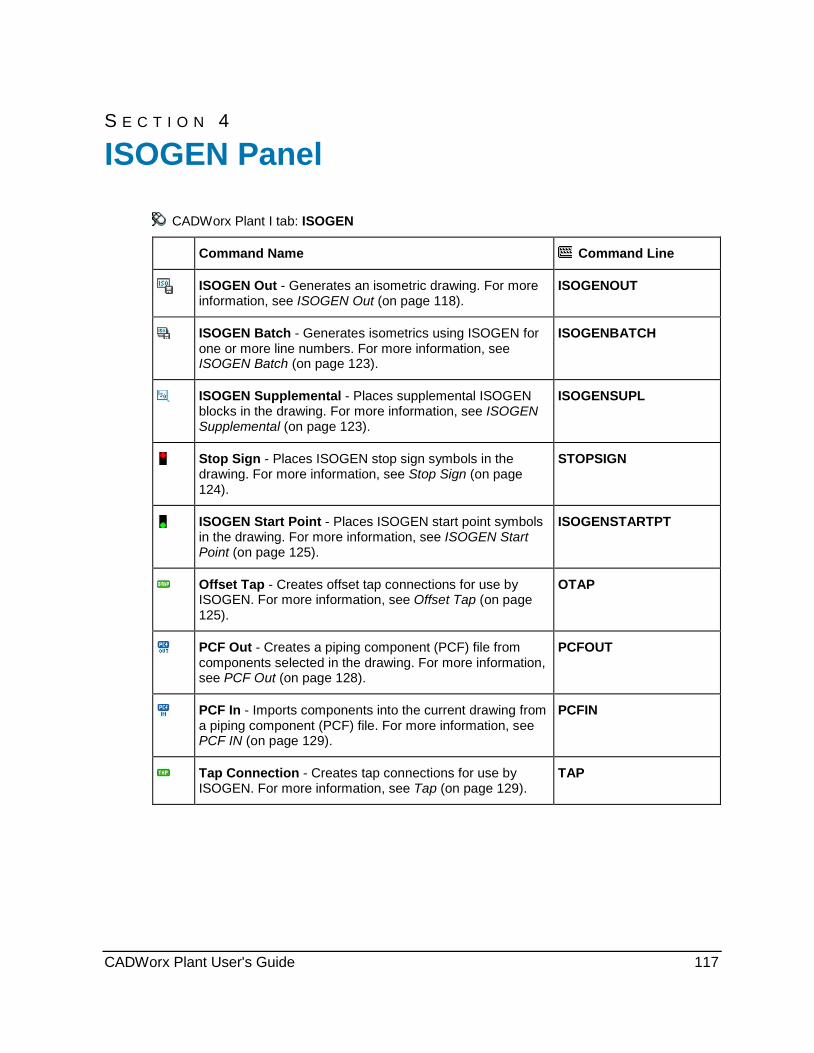
S E C T I O N 4
CADWorx Plant I tab: ISOGEN
Command Name Command Line
ISOGEN Out - Generates an isometric drawing. For more information, see ISOGEN Out (on page 118).
ISOGENOUT
ISOGEN Batch - Generates isometrics using ISOGEN for one or more line numbers. For more information, see ISOGEN Batch (on page 123).
ISOGENBATCH
ISOGEN Supplemental - Places supplemental ISOGEN blocks in the drawing. For more information, see ISOGEN Supplemental (on page 123).
ISOGENSUPL
Stop Sign - Places ISOGEN stop sign symbols in the drawing. For more information, see Stop Sign (on page 124).
STOPSIGN
ISOGEN Start Point - Places ISOGEN start point symbols in the drawing. For more information, see ISOGEN Start Point (on page 125).
ISOGENSTARTPT
Offset Tap - Creates offset tap connections for use by ISOGEN. For more information, see Offset Tap (on page 125).
OTAP
PCF Out - Creates a piping component (PCF) file from components selected in the drawing. For more information, see PCF Out (on page 128).
PCFOUT
PCF In - Imports components into the current drawing from a piping component (PCF) file. For more information, see PCF IN (on page 129).
PCFIN
Tap Connection - Creates tap connections for use by ISOGEN. For more information, see Tap (on page 129).
TAP
ISOGEN Panel
CADWorx Plant User's Guide 117

ISOGEN Panel
ISOGEN Out CADWorx Plant I tab: ISOGEN > ISOGEN Out Plant menu: Accessory > ISOGEN > ISOGEN Out Command line: ISOGENOUT
Generates an isometric drawing. The components you select to use with this command must be generated with an authorized ISOGEN hardware lock, or this function cannot process them. The selection process has different options that allow you to perform more detailed selections.
You can resubmit ISOGEN drawings after you make changes to your CADWorx drawing.
The software displays the drawings in their previous isometric layout with the added components. You must define the Repeatability return report in I-Configure for resubmitted drawings to display. To set the ISOGEN repeatability feature, see Enable the Repeatability return report (on page 120). If you delete an ISOGEN start or stop point, the software permanently
removes the points. This can affect the repeatability output. Use ISOGENRESET to remove the sheet and part numbers, and all Start/Stop signs from
component iso information. ISOGEN drawings can be created for curved piping by using ISOGEN Out on an
Adjustable Bend (on page 384). Before you run ISOGEN Out , make sure to set the SKEY in the ISOGEN Data Dialog Box (on page 73) to PB** (** designates a valid ISOGEN end type). Select the Overwrite check box to enter the new SKEY. To setup curved piping in isometrics, see Enable curved piping in Plant isometrics (on page 122).
Select ISOGEN Style Dialog Box Controls parameters for selecting ISOGEN projects, styles, and names of the automatically-generated isometrics. See ISOGEN Project Manager / I-Configure (on page 130) for more in information on creating and managing these projects and styles. Directory - Specifies the directory of the ISOGEN project. Project - Specifies the active project. The list contains all of the available projects. See ISOGEN Project Manager / I-Configure (on page 130) for information on creating these projects. Style - Specifies the active style. The list contains all of the available styles in the project. File Name - Specifies the name of the file. This allows you to name an isometric file if none of the components selected contain a line number. If the selected components contain line number information, the line number from the last component selected is used as the isometric file name. Path - Displays the Isometric folder that is used by the ISOGEN style. Select - Displays the Select Isogen Style Directory dialog box so that you can select an ISOGEN Style (ISOGEN.FLS) file. Use this command to select an ISOGEN style that is in a shared network folder. For more information, see ISOGEN Out (on page 118). Settings - Displays the ISOGEN Settings dialog box so that you can transpose the system by an X, Y, and Z offset distance. For more information, see ISOGEN Out (on page 118).
Use ISOGENRESET to remove the sheet and part numbers and all Start/Stop signs from component iso information.
The DXF edit box enables you to name a portion of the output file. The name appends a series of numbers. ISOGEN might break up the selected components into multiple sheets which would require this numbering sequence.
118 CADWorx Plant User's Guide

ISOGEN Panel Enable the RepeatFile for I-Configure 2012 1. Open I-Configure, select an isometric drawing style, and then select the Detail tab. 2. Expand Supplementary in the list, and then select RepeatFile. 3. In the Property panel, set Enabled value to True. Select ISOGEN Style Directory Dialog Box Controls parameters for selecting an ISOGEN style directory file. Look in - Specifies the folder in which the file resides. File name - Specifies the style directory file name. Files of type - Specifies the file type (extension). ISOGEN Settings Dialog Box Controls parameters for transposing the system by X, Y, and Z offsets. The whole system can be rotated by any angle. This allows any user-defined north arrow direction.
X - Specifies the X-direction offset. Y - Specifies the Y-direction offset. Z - Specifies the Z-direction offset. Angle - Specifies the north arrow direction: 90 = World positive Y-axis as north direction. This is the default value. 180 = World positive X-axis as north direction. 270 = World negative Y-axis as north direction. 0 = World negative X-axis as north direction. ISOGEN Project Data Setup Dialog Box Controls parameters for setting position text (POS) that can be displayed on the isometric drawing file. Review the [Product Folder]\Plant\Isogen\Isogen_Utils\POS_Help.pdf file to locate the POS number associated with each item. These values are stored with the configuration file and are used when an isometric is exported. For I-Configure projects, this is the only option for setting these values. For Project Manager projects, these values can be set from the Project Manager > Project Default dialog boxes or with this dialog box.
After typing a value, click the Use check box to store the value in the configuration file. To delete a value from the configuration file, clear the Use box. The values that have the Use box selected display at the top of the dialog box the next time it displays. ISOGEN Results Dialog Box Controls parameters for reviewing the results of the ISOGEN extraction. The dialog box displays the success or failure of the extraction in a text box. Open Plot Files - Opens all the generated ISOs in the current session of AutoCAD. The AutoCAD SDI setting must be set to 0 for the option to be available. View Message File - Opens Notepad to display a message file that provides information that could be used when an error was produced. The text file that displays is an .MES file. For more information, read the ISOGEN documentation.
What do you want to do? Extract ISOGEN files (on page 120) Enable the Repeatability return report (on page 120) Setup short description column for material list with text wrapping (on page 121) Enable curved piping in Plant isometrics (on page 122)
CADWorx Plant User's Guide 119
ISOGEN Panel
Extract ISOGEN files 1. Click ISOGEN Out . Alternatively, type ISOGENOUT on the command line, and press
ENTER.
The Select ISOGEN Style dialog box displays.
2. Set up the parameters to meet your requirements.
3. Click OK on the Select ISOGEN Style dialog box.
Enter an option [Line number/Select component] <Select component>.
4. Select Line Number to select components using line numbers.
Enter an option [List/Select component] <Select component>.
5. Choose List to select the line number from a list. For more information, see Select Item Dialog Box (on page 166).
or
Choose Select component to select the components by crossing, window, or any other preferred method. You can select components that are from an XREF if the UseObjectsFromXrefs (on page 46) is set to 1.
Processed 164 component(s) to file.
The components must have been generated with a valid ISOGEN authorized hardware lock. If not, a message similar to the following displays:
Could NOT process 17 component(s) due to permissions failure... Only components drawn with the ISOGEN interface are allowed... No components were written to file... The ISOGEN Results dialog box displays.
Enable the Repeatability return report 1. Click Start > All Programs > CADWorx > ISOGEN > I-Configure > I-Configure.
I-Configure opens.
2. In the Project View panel, select the appropriate isometric directory and project.
3. Under the active project, select the appropriate isometric drawing style.
4. Click Edit in the Properties panel.
The ISOGEN Configuration Home screen displays.
5. Click Reports in the Drawing Manager pane.
The Configuration view opens and displays the Reports panel.
6. Expand Report Types.
7. Double-click Repeatability return to open the data grid.
The Reports panel displays the Repeatability return options.
8. Expand File Formatting.
The File Formatting properties display.
120 CADWorx Plant User's Guide
ISOGEN Panel 9. Select Revised ASCII from the Content list.
10. Use the Part Numbers, Split Points, Start Point, and Weld Numbers check boxes control the information that displays in the drawing.
11. Set Spool Identifier to Numeric or Alphabetic.
12. In the Report Location box, type the name and full path location of the report file. Alternatively, click the Report Location browse button and navigate to the appropriate file.
13. Click to update the active style file with the new property settings.
14. Select Home in the menu to return to the Home screen.
15. Close ISOGEN Configuration.
16. Verify the Reports displays in the Properties panel, and that Value is set to REPEATABILITY-RETURN.
17. Click Export Style on the I-Configure horizontal toolbar.
For more information on Reports, see Report Definition Panel in the ISOGEN Configuration User's Guide.
Setup short description column for material list with text wrapping
1. Click Start > All Programs > CADWorx > ISOGEN > I-Configure > I-Configure.
I-Configure opens.
2. In the Project View panel, select the appropriate isometric directory and project.
3. Under the active project, select the appropriate isometric drawing style.
4. Click Edit in the Properties panel.
The ISOGEN Configuration Home screen displays.
5. Click Drawing Material List in the Materials pane.
The Configuration view opens and displays the Drawing Material List panel.
6. Expand User Defined Columns.
7. Click Show to open the data grid.
The User Defined Columns properties list displays.
8. Verify that there is a -80 value in the Attribute column. If there is none, select -80 from the Attribute list.
9. Verify the offset value. If you created a new -80 attribute, then you must also add an offset value.
10. Verify the Maximum Characters value. If you created a new -80 attribute, then you must also add a Maximum Characters value.
11. Click to update the active style file with the new property settings.
CADWorx Plant User's Guide 121
ISOGEN Panel
12. Select Home in the menu to return to the Home screen.
13. Click Drawing File in the Drawing Manager pane.
The Configuration view opens and displays the Drawing File panel.
14. Expand Template File.
15. Verify that Format is set to Smart DWG (DWG).
16. Type the full path location and file name of the template file that contains the correct material list information in the Path box. Alternatively, click the browse button and navigate to the appropriate file.
The template file displays in the Path box.
17. Click to update the active style file with the new property settings.
18. Close ISOGEN Configuration.
19. Click Export Style on the I-Configure horizontal toolbar.
Your material list now displays with the short description and the lines do not overlap, but are text wrapped.
Enable curved piping in Plant isometrics 1. Click Start > All Programs > CADWorx > ISOGEN > I-Configure > I-Configure.
I-Configure opens.
2. In the Project View panel, select the appropriate isometric directory and project.
3. Under the active project, select the appropriate isometric drawing style.
4. Click Edit in the Properties panel.
The ISOGEN Configuration Home screen displays.
5. Click Piping Components and Features in the Dimensions pane.
The Configuration view opens and displays the Piping Components and Features panel.
6. Expand Curved Pipe.
7. Type a value greater than zero in the Threshold box.
The bend radius (inches) is divided by the nominal size (pipe diameter in inches). If the result is lower than the Threshold setting, normal bends are drawn. If the result is greater than the Threshold setting curves are drawn.
8. Click outside the Threshold box to set the new value.
9. Click to update the active style file with the new property settings.
10. Close ISOGEN Configuration.
11. Click Export Style on the I-Configure horizontal toolbar.
To use this feature you need to draw an adjustable bend using the BENT command. You also need to update the SKEY of the new bend to PB** (** designates a valid ISOGEN end type) in the ISOGEN Data Dialog Box (on page 73). For more information, see Adjustable Bend (on page 384).
122 CADWorx Plant User's Guide
ISOGEN Panel
ISOGEN Batch CADWorx Plant I tab: ISOGEN > ISOGEN Batch
Plant menu: Accessory > ISOGEN > ISOGEN Batch
Command line: ISOGENBATCH
Generates isometrics using ISOGEN for one or more line numbers. The command uses the default settings from the ISOGEN Project Manager. For more information, see ISOGEN Project Manager / I-Configure (on page 130).
ISOGEN drawings can be created for curved piping by using ISOGEN Batch on an Adjustable Bend (on page 384) with SKEY in the ISOGEN Data Dialog Box (on page 73) set to PB** (** designates a valid ISOGEN end type). You need to check the Overwrite check box to enter the new SKEY. To setup curved piping in isometrics, see Enable curved piping in Plant isometrics (on page 122).
ISOGENBATCH also exports line number continuation information to ISOGEN.
Extract batch ISOGEN files 1. Click ISOGEN Batch . Alternatively, type ISOGENBATCH on the command line, and
press ENTER.
The software displays the Select Item dialog box which lists all the line numbers available in the model.
2. Select one or more from the available line numbers. For more information, see Select Item Dialog Box (on page 166).
CADWorx sends each line number to ISOGEN for processing. ISOGEN might break up the selected line numbers into multiple sheets.
ISOGENBATCH log file written to: C:\Drawings\Model_ISOGEN.log
The components must be generated with a valid ISOGEN authorized hardware lock. If not, a message similar to the following displays.
Could NOT process 17 component(s) due to permissions failure... Only components drawn with the ISOGEN interface are allowed... No components were written to file... As each line is processed, any errors encountered are displayed on the screen, and a log file is created. The ISOGEN Results dialog box displays. For more information, see ISOGEN Out (on page 118).
ISOGEN Supplemental CADWorx Plant I tab: ISOGEN > ISOGEN Supplemental
Plant menu: Accessory > ISOGEN > ISOGEN Supplemental
Command line: ISOGENSUPL
Places supplemental ISOGEN blocks in the drawing. There are several types of block available for export to ISOGEN:
CADWorx Plant User's Guide 123
ISOGEN Panel ISOGEN_Arrow
ISOGEN_Wall
ISOGEN_Floor
ISOGEN_Instrument
ISOGEN_BreakIn
Arrow, wall, and floor blocks must be inserted along the center line of a pipe component.
Instrument blocks must have the instrument line connected to the end of an olet component, TAP component, or a weld gap component.
Break in (Tie in) points must be connected to the end point of a component.
To add other blocks to this menu, see Introduction. The block name must contain ISOGEN_Arrow, ISOGEN_Instrument, ISOGEN_Wall, ISOGEN_Floor, or ISOGEN_BreakIn for export to ISOGEN. For example, to add another instrument type, you could name the block ISOGEN_Instrument_4, and add it to the menu.
If you are placing a flow arrow on a sloped line, align the UCS to the slope before inserting the arrow.
ISOGEN Supplemental Dialog Box Controls parameters for placing supplemental ISOGEN blocks in the drawing.
The folder containing the ISOGEN supplemental blocks displays at the top of the dialog box.
List - Displays the available ISOGEN supplemental blocks.
Preview - Displays a preview of the selected block.
Stop Sign CADWorx Plant I tab: Stop Sign
Misc toolbar: Stop Sign
Command line: STOPSIGN
Places stop sign symbols in the drawing. This symbol is used for designating the starting and ending locations for automatically-generated isometric output. For more information, see ISOGEN Out (on page 118). Stop signs must be at a weld or connection point on the piping system. You place these designators on the drawing and then export them to the database. This could occur manually with Export Pipe (on page 165) or automatically with Setup Live Database (on page 164).
If stop signs are present when using the Database option of the ISOOUT command, you are asked if stop signs should be used in generating the ISOs.
Use Stop Signs [Yes/No] <Yes>:
If you select Yes, continuity is checked and the ISOs are broken at each stop sign. If there are no line numbers or stop signs present in the database, the following prompt displays.
Database does not have any line number or stop signs...
When exporting with the Select ISOGEN Style dialog box isometric generator (ISOGEN Out (on page 118) or ISOGEN Batch (on page 123)), stop signs are used, if selected.
124 CADWorx Plant User's Guide
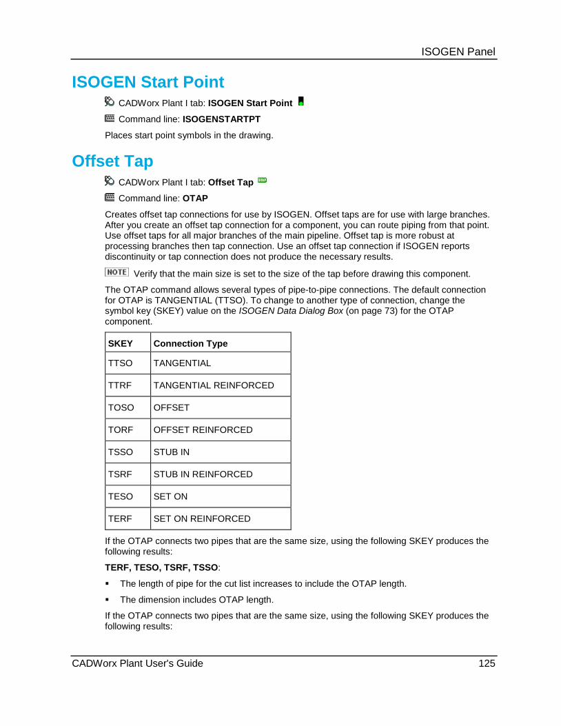
ISOGEN Panel
ISOGEN Start Point CADWorx Plant I tab: ISOGEN Start Point
Command line: ISOGENSTARTPT
Places start point symbols in the drawing.
Offset Tap CADWorx Plant I tab: Offset Tap
Command line: OTAP
Creates offset tap connections for use by ISOGEN. Offset taps are for use with large branches. After you create an offset tap connection for a component, you can route piping from that point. Use offset taps for all major branches of the main pipeline. Offset tap is more robust at processing branches then tap connection. Use an offset tap connection if ISOGEN reports discontinuity or tap connection does not produce the necessary results.
Verify that the main size is set to the size of the tap before drawing this component.
The OTAP command allows several types of pipe-to-pipe connections. The default connection for OTAP is TANGENTIAL (TTSO). To change to another type of connection, change the symbol key (SKEY) value on the ISOGEN Data Dialog Box (on page 73) for the OTAP component.
SKEY Connection Type
TTSO TANGENTIAL
TTRF TANGENTIAL REINFORCED
TOSO OFFSET
TORF OFFSET REINFORCED
TSSO STUB IN
TSRF STUB IN REINFORCED
TESO SET ON
TERF SET ON REINFORCED
If the OTAP connects two pipes that are the same size, using the following SKEY produces the following results:
TERF, TESO, TSRF, TSSO:
The length of pipe for the cut list increases to include the OTAP length.
The dimension includes OTAP length.
If the OTAP connects two pipes that are the same size, using the following SKEY produces the following results:
CADWorx Plant User's Guide 125
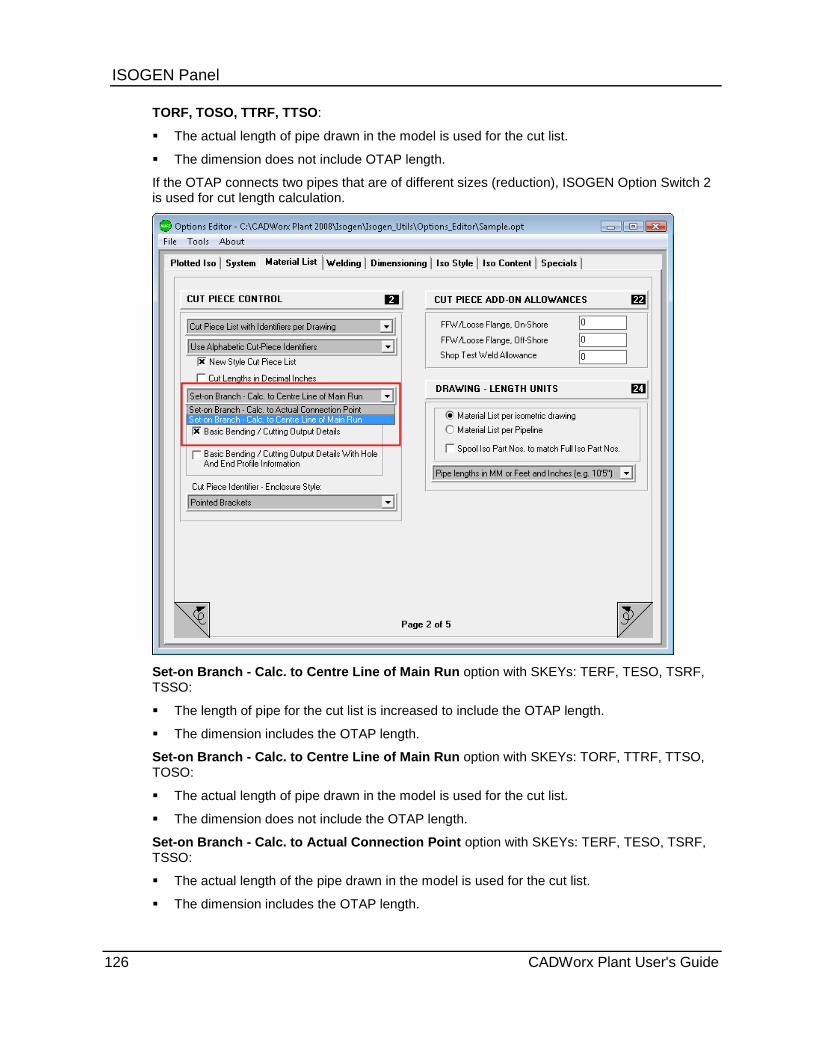
ISOGEN Panel TORF, TOSO, TTRF, TTSO:
The actual length of pipe drawn in the model is used for the cut list.
The dimension does not include OTAP length.
If the OTAP connects two pipes that are of different sizes (reduction), ISOGEN Option Switch 2 is used for cut length calculation.
Set-on Branch - Calc. to Centre Line of Main Run option with SKEYs: TERF, TESO, TSRF, TSSO:
The length of pipe for the cut list is increased to include the OTAP length.
The dimension includes the OTAP length.
Set-on Branch - Calc. to Centre Line of Main Run option with SKEYs: TORF, TTRF, TTSO, TOSO:
The actual length of pipe drawn in the model is used for the cut list.
The dimension does not include the OTAP length.
Set-on Branch - Calc. to Actual Connection Point option with SKEYs: TERF, TESO, TSRF, TSSO:
The actual length of the pipe drawn in the model is used for the cut list.
The dimension includes the OTAP length.
126 CADWorx Plant User's Guide

ISOGEN Panel Set-on Branch - Calc. to Actual Connection Point option with SKEYs: TORF, TTRF, TTSO:
The length of the pipe for the cut list is adjusted based on the diameter of the main and reduction pipe sizes.
The dimension does not include the OTAP length.
Set-on Branch - Calc. to Actual Connection Point setting with SKEYs: TOSO:
The actual length of the pipe drawn in the model is used for the cut list.
The dimension does not include the OTAP length.
Option switch 77 Generate PAD Item Code and Show Symbol on Iso option shows a reinforcement pad on OTAP connections with SKEYs: TTRF, TORF, TERF. A CADWorx reinforcement pad does not have to be drawn in the model for these three SKEYs.
For all other SKEYs, a CADWorx reinforcement pad must be drawn in the model for it to appear in the ISO drawing.
CADWorx Plant User's Guide 127

ISOGEN Panel ISOGEN option switch 77 No Extra Welds added at Reinforcement Pads, One Extra Weld added at Reinforcement Pads, and Two Extra Welds added at Reinforcement Pads settings control weld numbering at the reinforcement pads. Extra welds are only shown for the following SKEYs: TTRF, TORF, TERF.
Place an offset tap 1. Click Offset Tap . Alternatively, type OTAP on the command line, and press ENTER. 2. Select a point for the tap. This point is normally the inner most endpoint of the tapping
component. 3. Select a point on the center line of the component that is being taped.
The software places the offset tap.
PCF Out CADWorx Plant I tab: ISOGEN > PCF Out
Plant menu: Accessory > ISOGEN > PCF Out
Command line: PCFOUT
Creates a piping component (PCF) file from components selected in the drawing.
This command displays the standard file selection dialog box and prompts for a file name.
128 CADWorx Plant User's Guide
ISOGEN Panel
Extract piping component files 1. Click PCF Out . Alternatively, type PCFOUT on the command line, and press ENTER.
The Create dialog box displays.
2. Type the name of the PCF file in the File name box, and click Save.
Enter an option [Line number/Select component] <Select component>.
3. Select Line Number to select components using line numbers.
Enter an option [List/Select component] <Select component>.
4. Choose List to select the line number from a list. For more information, see Select Item Dialog Box (on page 166).
or
Choose Select component to select the components by crossing, window, or any other preferred method. You can select components that are from an XREF if the UseObjectsFromXrefs (on page 46) is set to 1.
The software processes the components.
PCF In CADWorx Plant I tab: ISOGEN > PCF In
Plant menu: Accessory > ISOGEN > PCF In
Command line: PCFIN
Imports components into the current drawing from a piping component (PCF) file. The PCF file is usually produced from some other plant design system. This command requires that proper CADWorx specification and data files exist. If the PCF file uses a specification that does not match the CADWorx specification exactly, the model created by PCF In does not function as expected.
The function displays a standard file selection dialog box. There is an intervention level. For more information, see System In (on page 206).
Tap CADWorx Plant I tab: Tap
Command line: TAP
Creates tap connections for use by ISOGEN. The tap connections are used for small branches. After creating a tap connection for a component, piping can be routed from that point. The CADWorx ISOGEN interface automatically processes numerous types of taps without needing a tap connection. Only use a tap connection if ISOGEN reports a discontinuity.
Verify that the main size is set to the size of the tap before drawing this component.
CADWorx Plant User's Guide 129

ISOGEN Panel
Place a tap 1. Click Tap . Alternatively, type TAP on the command line, and press ENTER.
2. Select a point for the tap. This point is normally the inner most endpoint of the tapping component.
3. Select a point on the center line of the component that is being taped.
The software places the tap.
ISOGEN Project Manager / I-Configure Generates isometrics. All of the software included with ISOGEN is supplied with an Adobe Acrobat Portable Document Format (PDF) file. This PDF file can be printed or viewed from the computer. The PDFs can be accessed from the program group that is created during installation. We suggest reading the PDF manual prior to contacting for technical support.
ISOGEN is installed in a subfolder of CADWorx. There is not an option to install it anywhere else. The program group created during installation provides shortcuts to all the software within these folders. It also provides shortcuts for all the documentation.
The information supplied in the CADWorx help file is for general use only.
The Isogen_Utils folder contains all the editors that are used to control the format of the automatically generated isometrics. These utilities include the options editor, symbols editor, and others. These applications are required to control the appearance of the ISOGEN isometric. All of the applications have shortcuts in the program group.
There are two applications available for creating and maintaining ISOGEN Styles: Project Manager and I-Configure.
Project Manager and I-Configure are both installed with CADWorx ISOGEN and are located in the [Product Folder]\Plant\ISOGEN folder.
CADWorx can use ISOGEN styles created by Project Manager or I-Configure.
ISOGEN Information The following topics provide general ISOGEN information.
Material List Definition The Material List Definition (MLD) file allows you to customize the ISOGEN material list. The following table shows how CADWorx data is exported to an ISOGEN material list for use with the MLD file.
CADWorx data (as listed in component edit dialog box)
ISOGEN MLD
Alpha size Not exported ('N.S.' in the MLD is based on the size stored within the component data.)
Short annotation 'COMPONENT-ATTRIBUTE2'
Short annotation -80
130 CADWorx Plant User's Guide

ISOGEN Panel Long annotation 'DESCRIPTION'
Line Number Not available as an MLD item.
Tag 'COMPONENT-ATTRIBUTE3'
Code 'ITEM-CODE'
(If DataBaseCodesISOGEN (on page 36) = Yes in current configuration settings)
Code 'COMPONENT-ATTRIBUTE4'
(If DataBaseCodesISOGEN (on page 36) = No in current configuration settings)
Weight 'WEIGHT'
Sort sequence Not exported
Length 'QTY'
Specification 'COMPONENT-ATTRIBUTE1'
SKEY Information The following ISOGEN SKEYs can be used by CADWorx when creating an isometric.
ISOGEN SKEY definitions and symbol shapes are available in the ISOGEN Symbol Key (SKEY) Definitions Reference Guide. You can access this document with the Help > Printable Guides command in I-Configure.
PRGM # CADWorx Name ISOGEN Identifier SKEY
1 PIPE PIPE (Blank)
2 ELBOW 90 LR BUTTWELD ELBOW ELBW
3 ELBOW 90 SR BUTTWELD ELBOW ELBW
4 ELBOW 90 REDUCING BUTTWELD ELBOW-REDUCING ERBW
5 ELBOW 45 BUTTWELD ELBOW ELBW
6 BEND 180 LR RETURN BUTTWELD ELBOW EUBW
7 BEND 180 SR RETURN BUTTWELD ELBOW EUBW
8 TEE STRAIGHT BUTTWELD TEE TEBW
9 TEE REDUCING BUTTWELD TEE TEBW
CADWorx Plant User's Guide 131

ISOGEN Panel PRGM # CADWorx Name ISOGEN Identifier SKEY
10 REDUCER CONCENTRIC BUTTWELD REDUCER-CONCENTRIC RCBW
11 REDUCER ECCENTRIC BUTTWELD REDUCER-ECCENTRIC REBW
12 CAP BUTTWELD CAP KABW
13 STRAIGHT CROSS BUTTWELD CROSS CRBW
14 REDUCING CROSS BUTTWELD CROSS CRBW
15 LATERAL BUTTWELD TEE TSBW
16 STUB END BUTTWELD LAPJOINT-STUBEND FLSE
17 LONG WELD NECK FLANGE / NOZZLE FLWN / NZFS
18 FLANGE WELD NECK FLANGE FLWN
19 FLANGE SLIP ON FLANGE FLSJ
20 FLANGE BLIND FLANGE-BLIND FLBL
21 FLANGE LAP JOINT FLANGE FLLB
22 FLANGE SOCKET WELD FLANGE FLSW
23 FLANGE THREADED FLANGE FLSC
24 BOLT BOLT (Blank)
25 GASKET GASKET (Blank)
26 NIPPLE COUPLING NRSC
27 CONCENTRIC SWAGE REDUCER-CONCENTRIC CSPL
28 ECCENTRIC SWAGE REDUCER-ECCENTRIC ESPL
29 90 LR ELBOW SOCKET WELD ELBOW ELSW
30 90 STREET ELBOW SOCKET WELD ELBOW ELSW
31 90 REDUCING ELBOW SOCKET WELD ELBOW-REDUCING ERSW
32 45 ELBOW SOCKET WELD ELBOW ELSW
132 CADWorx Plant User's Guide
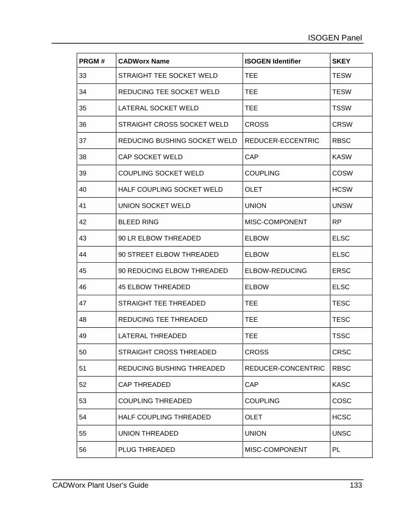
ISOGEN Panel PRGM # CADWorx Name ISOGEN Identifier SKEY
33 STRAIGHT TEE SOCKET WELD TEE TESW
34 REDUCING TEE SOCKET WELD TEE TESW
35 LATERAL SOCKET WELD TEE TSSW
36 STRAIGHT CROSS SOCKET WELD CROSS CRSW
37 REDUCING BUSHING SOCKET WELD REDUCER-ECCENTRIC RBSC
38 CAP SOCKET WELD CAP KASW
39 COUPLING SOCKET WELD COUPLING COSW
40 HALF COUPLING SOCKET WELD OLET HCSW
41 UNION SOCKET WELD UNION UNSW
42 BLEED RING MISC-COMPONENT RP
43 90 LR ELBOW THREADED ELBOW ELSC
44 90 STREET ELBOW THREADED ELBOW ELSC
45 90 REDUCING ELBOW THREADED ELBOW-REDUCING ERSC
46 45 ELBOW THREADED ELBOW ELSC
47 STRAIGHT TEE THREADED TEE TESC
48 REDUCING TEE THREADED TEE TESC
49 LATERAL THREADED TEE TSSC
50 STRAIGHT CROSS THREADED CROSS CRSC
51 REDUCING BUSHING THREADED REDUCER-CONCENTRIC RBSC
52 CAP THREADED CAP KASC
53 COUPLING THREADED COUPLING COSC
54 HALF COUPLING THREADED OLET HCSC
55 UNION THREADED UNION UNSC
56 PLUG THREADED MISC-COMPONENT PL
CADWorx Plant User's Guide 133

ISOGEN Panel PRGM # CADWorx Name ISOGEN Identifier SKEY
57 SOCKET WELD ELL-O-LET ELBOLET CESW
58 THREADED ELL-O-LET ELBOLET CESC
59 WELD ELL-O-LET ELBOLET CEBW
60 SOCK-O-LET OLET SKSW
61 THREAD-O-LET OLET THSC
62 WELD-O-LET OLET WTBW
63 BALL VALVE FLANGED or BUTTWELD VALVE VBFL or VBBW
64 BALL VALVE SOCKET WELD VALVE VBSW
65 BALL VALVE THREADED VALVE VBSC
66 BUTTERFLY VALVE FLANGED or BUTTWELD
VALVE VYFL or VYBW
67 CHECK VALVE FLANGED or BUTTWELD
VALVE CKFL or CKBW
68 CHECK VALVE SOCKET WELD VALVE CKSW
69 CHECK VALVE THREADED VALVE CKSC
70 GATE VALVE FLANGED or BUTTWELD VALVE VTFL or VTBW
71 GATE VALVE SOCKET WELD VALVE VTSW
72 GATE VALVE THREADED VALVE VTSC
73 GLOBE VALVE FLANGED or BUTTWELD
VALVE VGFL or VGBW
74 GLOBE VALVE SOCKET WELD VALVE VGSW
75 GLOBE VALVE THREADED VALVE VGSC
76 PLUG VALVE FLANGED or BUTTWELD VALVE VPFL or VPBW
77 PLUG VALVE SOCKET WELD VALVE VPSW
134 CADWorx Plant User's Guide

ISOGEN Panel PRGM # CADWorx Name ISOGEN Identifier SKEY
78 PLUG VALVE THREADED VALVE VPSC
79 RELIEF VALVE FLANGED or BUTTWELD
VALVE-ANGLE ARFL or ARBW
80 RELIEF VALVE SOCKET WELD VALVE-ANGLE ARSW
81 RELIEF VALVE THREADED VALVE-ANGLE ARSC
82 NEEDLE VALVE SOCKET WELD VALVE VNSW
83 NEEDLE VALVE THREADED VALVE VNSC
84 3-WAY VALVE FLANGED or BUTTWELD
VALVE-3WAY V3FL or V3BW
85 3-WAY VALVE SOCKET WELD VALVE-3WAY V3SW
86 3-WAY VALVE THREADED VALVE-3WAY V3SC
87 4-WAY FLANGED or BUTTWELD VALVE-4WAY V4FL or V4BW
88 4-WAY SOCKET WELD VALVE-4WAY V4SW
89 4-WAY VALVE THREADED VALVE-4WAY V4SC
90 CONTROL VALVE FLANGED or BUTTWELD
INSTRUMENT CVFL
91 CONTROL VALVE SOCKET WELD INSTRUMENT CVSW
92 CONTROL VALVE THREADED INSTRUMENT CVSC
93 STRAINER FLANGED or BUTTWELD FILTER FIFL
94 STRAINER SOCKET WELD FILTER FISW
95 STRAINER THREADED FILTER FISC
96 ANGLE VALVE FLANGED or BUTTWELD
VALVE-ANGLE AVFL or AVBW
97 ANGLE VALVE SOCKET WELD VALVE-ANGLE AVSW
98 ANGLE VALVE THREADED VALVE-ANGLE AVSC
CADWorx Plant User's Guide 135
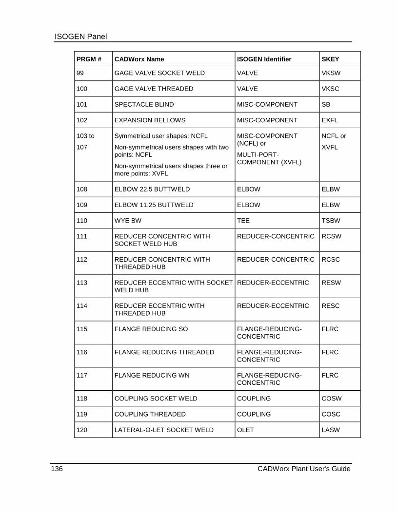
ISOGEN Panel PRGM # CADWorx Name ISOGEN Identifier SKEY
99 GAGE VALVE SOCKET WELD VALVE VKSW
100 GAGE VALVE THREADED VALVE VKSC
101 SPECTACLE BLIND MISC-COMPONENT SB
102 EXPANSION BELLOWS MISC-COMPONENT EXFL
103 to
107
Symmetrical user shapes: NCFL
Non-symmetrical users shapes with two points: NCFL
Non-symmetrical users shapes three or more points: XVFL
MISC-COMPONENT (NCFL) or
MULTI-PORT-COMPONENT (XVFL)
NCFL or
XVFL
108 ELBOW 22.5 BUTTWELD ELBOW ELBW
109 ELBOW 11.25 BUTTWELD ELBOW ELBW
110 WYE BW TEE TSBW
111 REDUCER CONCENTRIC WITH SOCKET WELD HUB
REDUCER-CONCENTRIC RCSW
112 REDUCER CONCENTRIC WITH THREADED HUB
REDUCER-CONCENTRIC RCSC
113 REDUCER ECCENTRIC WITH SOCKET WELD HUB
REDUCER-ECCENTRIC RESW
114 REDUCER ECCENTRIC WITH THREADED HUB
REDUCER-ECCENTRIC RESC
115 FLANGE REDUCING SO FLANGE-REDUCING-CONCENTRIC
FLRC
116 FLANGE REDUCING THREADED FLANGE-REDUCING-CONCENTRIC
FLRC
117 FLANGE REDUCING WN FLANGE-REDUCING-CONCENTRIC
FLRC
118 COUPLING SOCKET WELD COUPLING COSW
119 COUPLING THREADED COUPLING COSC
120 LATERAL-O-LET SOCKET WELD OLET LASW
136 CADWorx Plant User's Guide
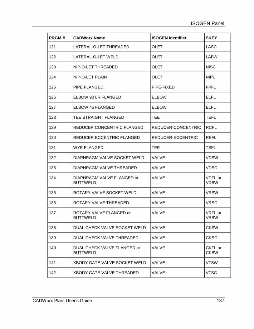
ISOGEN Panel PRGM # CADWorx Name ISOGEN Identifier SKEY
121 LATERAL-O-LET THREADED OLET LASC
122 LATERAL-O-LET WELD OLET LABW
123 NIP-O-LET THREADED OLET NISC
124 NIP-O-LET PLAIN OLET NIPL
125 PIPE FLANGED PIPE-FIXED FPFL
126 ELBOW 90 LR FLANGED ELBOW ELFL
127 ELBOW 45 FLANGED ELBOW ELFL
128 TEE STRAIGHT FLANGED TEE TEFL
129 REDUCER CONCENTRIC FLANGED REDUCER-CONCENTRIC RCFL
130 REDUCER ECCENTRIC FLANGED REDUCER-ECCENTRIC REFL
131 WYE FLANGED TEE TSFL
132 DIAPHRAGM VALVE SOCKET WELD VALVE VDSW
133 DIAPHRAGM VALVE THREADED VALVE VDSC
134 DIAPHRAGM VALVE FLANGED or BUTTWELD
VALVE VDFL or VDBW
135 ROTARY VALVE SOCKET WELD VALVE VRSW
136 ROTARY VALVE THREADED VALVE VRSC
137 ROTARY VALVE FLANGED or BUTTWELD
VALVE VRFL or VRBW
138 DUAL CHECK VALVE SOCKET WELD VALVE CKSW
139 DUAL CHECK VALVE THREADED VALVE CKSC
140 DUAL CHECK VALVE FLANGED or BUTTWELD
VALVE CKFL or CKBW
141 XBODY GATE VALVE SOCKET WELD VALVE VTSW
142 XBODY GATE VALVE THREADED VALVE VTSC
CADWorx Plant User's Guide 137
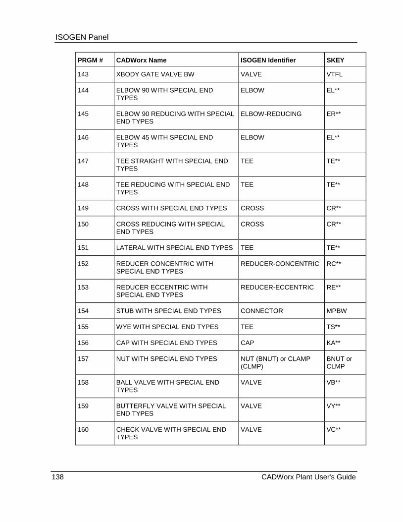
ISOGEN Panel PRGM # CADWorx Name ISOGEN Identifier SKEY
143 XBODY GATE VALVE BW VALVE VTFL
144 ELBOW 90 WITH SPECIAL END TYPES
ELBOW EL**
145 ELBOW 90 REDUCING WITH SPECIAL END TYPES
ELBOW-REDUCING ER**
146 ELBOW 45 WITH SPECIAL END TYPES
ELBOW EL**
147 TEE STRAIGHT WITH SPECIAL END TYPES
TEE TE**
148 TEE REDUCING WITH SPECIAL END TYPES
TEE TE**
149 CROSS WITH SPECIAL END TYPES CROSS CR**
150 CROSS REDUCING WITH SPECIAL END TYPES
CROSS CR**
151 LATERAL WITH SPECIAL END TYPES TEE TE**
152 REDUCER CONCENTRIC WITH SPECIAL END TYPES
REDUCER-CONCENTRIC RC**
153 REDUCER ECCENTRIC WITH SPECIAL END TYPES
REDUCER-ECCENTRIC RE**
154 STUB WITH SPECIAL END TYPES CONNECTOR MPBW
155 WYE WITH SPECIAL END TYPES TEE TS**
156 CAP WITH SPECIAL END TYPES CAP KA**
157 NUT WITH SPECIAL END TYPES NUT (BNUT) or CLAMP (CLMP)
BNUT or CLMP
158 BALL VALVE WITH SPECIAL END TYPES
VALVE VB**
159 BUTTERFLY VALVE WITH SPECIAL END TYPES
VALVE VY**
160 CHECK VALVE WITH SPECIAL END TYPES
VALVE VC**
138 CADWorx Plant User's Guide

ISOGEN Panel PRGM # CADWorx Name ISOGEN Identifier SKEY
161 GATE VALVE WITH SPECIAL END TYPES
VALVE VT**
162 GLOBE VALVE WITH SPECIAL END TYPES
VALVE VG**
163 PLUG VALVE WITH SPECIAL END TYPES
VALVE VP**
164 3-WAY VALVE WITH SPECIAL END TYPES
VALVE-3WAY V3**
165 ANGLE VALVE WITH SPECIAL END TYPES
VALVE-ANGLE AV**
166 MULTIPORT 1 VALVE WITH SPECIAL END TYPES
VALVE, VALVE-ANGLE, VALVE-3WAY
ZG**, 2Z**, 3Z**
167 MULTIPORT 2 VALVE WITH SPECIAL END TYPES
VALVE-MULTIWAY MZ**
168 MULTIPORT 3 VALVE WITH SPECIAL END TYPES
VALVE-MULTIWAY MZ**
169 ELBOW 22.5 WITH SPECIAL END TYPES
BEND BE**
170 ELBOW 11.25 WITH SPECIAL END TYPES
BEND BE**
171 LATERAL REDUCING WITH SPECIAL END TYPES
TEE TE**
172 U-BEND WITH SPECIAL END TYPES Not exported Not exported
173 WELD GAP WELD WW
174 to 197 (Future Components)
198 GENERIC INSERT Not exported Not exported
199 WELD GAP WELD WW
200 BEND PIPE ELBOW, BEND ELBW, BUBW, PBBW,
CADWorx Plant User's Guide 139

ISOGEN Panel PRGM # CADWorx Name ISOGEN Identifier SKEY
201 MITER PIPE GAP (Blank)
202 ROLLED PIPE MISC-COMPONENT FXBW
203 RESTRAINTS SUPPORT SKID
204 PAD or SADDLE REINFORCEMENT-PAD (Blank)
205 RIGID ELEMENT GAP (Blank)
206 SKIPPED ELEMENT GAP (Blank)
207 SPECIAL RIGID GAP (Blank)
208 TUBING PIPE or BEND (PB) (Blank) or PB
209 STOP SIGN ISO-SPLIT-POINT (Blank)
210 TAP CONNECTION TAP-CONNECTION (Blank)
211 OFFSET TAP CONNECTION TEE-SET-ON TTSO
212 ISOGEN START POINT START-CO-ORDS (Blank)
End Type Information CADWorx special end type components are written to the PCF based on the end type used in the data file.
CADWorx End Type ISOGEN End Type
0 PL
1 BW
2 FL
3 LN
4 LN
5 MP
6 MP
7 MP
140 CADWorx Plant User's Guide

ISOGEN Panel 8 MP
9 CL
10 CL
11 CL
12 CL
13 CL
14 SW
15 SC
CADWorx Plant User's Guide 141

ISOGEN Panel
142 CADWorx Plant User's Guide
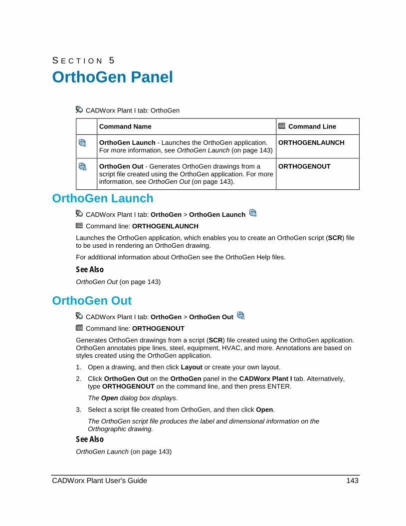
S E C T I O N 5
CADWorx Plant I tab: OrthoGen
Command Name Command Line
OrthoGen Launch - Launches the OrthoGen application. For more information, see OrthoGen Launch (on page 143)
ORTHOGENLAUNCH
OrthoGen Out - Generates OrthoGen drawings from a script file created using the OrthoGen application. For more information, see OrthoGen Out (on page 143).
ORTHOGENOUT
OrthoGen Launch CADWorx Plant I tab: OrthoGen > OrthoGen Launch
Command line: ORTHOGENLAUNCH
Launches the OrthoGen application, which enables you to create an OrthoGen script (SCR) file to be used in rendering an OrthoGen drawing.
For additional information about OrthoGen see the OrthoGen Help files.
See Also OrthoGen Out (on page 143)
OrthoGen Out CADWorx Plant I tab: OrthoGen > OrthoGen Out
Command line: ORTHOGENOUT
Generates OrthoGen drawings from a script (SCR) file created using the OrthoGen application. OrthoGen annotates pipe lines, steel, equipment, HVAC, and more. Annotations are based on styles created using the OrthoGen application.
1. Open a drawing, and then click Layout or create your own layout.
2. Click OrthoGen Out on the OrthoGen panel in the CADWorx Plant I tab. Alternatively, type ORTHOGENOUT on the command line, and then press ENTER.
The Open dialog box displays.
3. Select a script file created from OrthoGen, and then click Open.
The OrthoGen script file produces the label and dimensional information on the Orthographic drawing.
See Also OrthoGen Launch (on page 143)
OrthoGen Panel
CADWorx Plant User's Guide 143
OrthoGen Panel
144 CADWorx Plant User's Guide
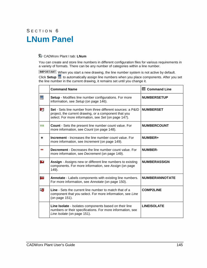
S E C T I O N 6
CADWorx Plant I tab: LNum
You can create and store line numbers in different configuration files for various requirements in a variety of formats. There can be any number of categories within a line number.
When you start a new drawing, the line number system is not active by default. Click Setup to automatically assign line numbers when you place components. After you set the line number in the current drawing, it remains set until you change it.
Command Name Command Line
Setup - Modifies line number configurations. For more information, see Setup (on page 146).
NUMBERSETUP
Set - Sets line number from three different sources: a P&ID project, the current drawing, or a component that you select. For more information, see Set (on page 147).
NUMBERSET
Count - Sets the present line number count value. For more information, see Count (on page 148).
NUMBERCOUNT
Increment - Increases the line number count value. For more information, see Increment (on page 149).
NUMBER+
Decrement - Decreases the line number count value. For more information, see Decrement (on page 149).
NUMBER-
Assign - Assigns new or different line numbers to existing components. For more information, see Assign (on page 149).
NUMBERASSIGN
Annotate - Labels components with existing line numbers. For more information, see Annotate (on page 150).
NUMBERANNOTATE
Line - Sets the current line number to match that of a component that you select. For more information, see Line (on page 151).
COMP2LINE
Line Isolate - Isolates components based on their line numbers or their specifications. For more information, see Line Isolate (on page 151).
LINEISOLATE
LNum Panel
CADWorx Plant User's Guide 145
LNum Panel
Setup CADWorx Plant I tab: LNum > Setup
Line Number toolbar: Setup
Plant menu: Accessory > Line Numbers > Setup
Command line: NUMBERSETUP
Modifies any line number configuration. You can turn the line numbering system on or off. If the system is on, it can operate in a static or dynamic mode.
In the dynamic mode, CADWorx adjusts the line number according to the size or specification. In the static mode, you must manually change the size and specification. Static is useful when all components and sizes of a particular piping run are required to have the same line number (such as, the 3/4” vent on an 8” process line needs a line number of 8”-150-2001-N). Static line numbering is also useful when selecting runs of piping for other functions with CADWorx. For more information, see LineNumberSystem (on page 41).
This system also works with a CADWorx P&ID setup configuration file. You can change the configuration file location in SETUP to use the same project configuration as any P&ID project. For more information, see Setup (on page 28). Click Add in the Category group in this dialog box to select additional fields located in the process lines table of a typical P&ID project database. When using a P&ID project, changes made to a line number configuration within CADWorx reflect within the P&ID project.
If the system is not using a CADWorx P&ID setup configuration file, the additional fields are obtained from the DATABASE.TBL file located in the [Product Folder]\Plant\System folder. You must manually edit this file for any modifications required of the existing fields within the default line number system.
Line Numbering System Dialog Box Controls parameters for line numbering systems. The name of the current configuration file displays at the top of the dialog box. You can also use a P&ID project configuration file.
Category - Specifies the active process line item. The list contains the process line items from the Database.TBL file in the [Product Folder]\Plant\System folder. You can add these items to any line number system. After you select an item, click Add to place it in the Category list. Highlight the item in the right list box, and then click Delete to remove it from the line number system. You can also type in a value, and then click Add.
Add - Adds the item from the Category box to the Category list.
Delete - Removes the selected item from the Category list.
Separator - Specifies a separator character. Type an alphanumeric value (including special characters such as -, ~, #, or SPACE). Click Add to place it in the Category list. Highlight the item in the Category list, and then click Delete to remove it from the line number system.
Add - Adds the separator character to the Category list.
Delete - Removes the separator character from the Category list.
Default Value - Adds any default value to any category included in the Category list. The size and specification are disabled if the system is set to the dynamic mode.
System Off - Indicates that line numbers are not placed in the drawing.
146 CADWorx Plant User's Guide
LNum Panel System On (Dynamic Size/Spec) - Indicates that each component placed in the drawing receives a line number. When this option is cleared, the line number is not placed on the component.
System On (Static Size/Spec) - Indicates that the line number system uses the value in the Default value box, including the size and specification. This allows you to type anything for the size and specification.
Preview - Displays the line number based on the selected categories. The line number added to components looks similar to the Preview value.
Move Up - Moves the selected item higher in the Category list. The new order also displays in the Preview box.
Move Down - Moves the selected item lower in the Category list. The new order also displays in the Preview box.
Set CADWorx Plant I tab: LNum > Set
Line Number toolbar: Set
Plant menu: Accessory > Line Numbers > Set
Command line: NUMBERSET
Sets the line number from one of three sources: a P&ID project, the current drawing, or a selected component.
P&ID - Requires a valid CADWorx P&ID project using an Access database. If the configuration file is the same as an existing P&ID project, this option automatically supplies all the line numbers within that project from the process lines table. The line numbers supplied are of the same format as the project. If the configuration file is not the same, a standard file dialog box displays requesting the location of the database to use.
Current Drawing - Sets the line numbers based on the current drawing. This option searches the entire drawing and displays all the line numbers in the Select Item dialog box. This option requires that the LineNumberSystem (on page 41) variable is set to 2. This is the same as selecting the System On (Static Size/Spec) option in the Line Numbering System dialog box. For more information, see Line Numbering System Dialog Box (on page 146).
Component - Sets the line numbers based on a component that you select from the current drawing. This option searches the entire drawing and displays all the line numbers in the Select Item dialog box. This option requires that the LineNumberSystem (on page 41) variable is set to 2. This is the same as selecting the System On (Static Size/Spec) option in the Line Numbering System dialog box. For more information, see Line Numbering System Dialog Box (on page 146).
Select Item Dialog Box (on page 166)
What do you want to do? Set line numbers based on a P&ID project (on page 148)
Set line numbers based on the current drawing (on page 148)
Set line numbers based on a component (on page 148)
CADWorx Plant User's Guide 147
LNum Panel
Set line numbers based on a P&ID project 1. Click Set . Alternatively, type NUMBERSET on the command line and press ENTER.
2. Type P on the command line and press ENTER, or select Process drawings from the popup menu.
The Select Database File dialog box displays.
3. Select the P&ID Access database file.
4. Click Open on the Select Database File dialog box.
The software sets the line numbers.
Set line numbers based on the current drawing 1. Click Set . Alternatively, type NUMBERSET on the command line and press ENTER.
2. Type D on the command line and press ENTER, or select current Drawing from the popup menu.
The Select Item dialog box displays.
3. If needed, use the Filter box to limit the items that display.
4. Select the item to use from the list.
5. Click OK.
The software sets the line numbers.
Set line numbers based on a component 1. Click Set . Alternatively, type NUMBERSET on the command line, and press ENTER.
2. Type C on the command line and press ENTER, or select Component from the popup menu.
3. Select the component in the drawing.
The software sets the line numbers.
Count CADWorx Plant I tab: LNum > Count
Line Number toolbar: Count
Plant menu: Accessory > Line Numbers > Count
Command line: NUMBERCOUNT
Sets the present line number count value.
This option requires that you set the LineNumberSystem (on page 41) variable to 1. This is the same as selecting the System On (Dynamic Size/Spec) option in the Line Numbering System dialog box. For more information, see Line Numbering System Dialog Box (on page 146).
148 CADWorx Plant User's Guide

LNum Panel
Set the line count value 1. Click Count . Alternatively, type NUMBERCOUNT on the command line, and press
ENTER.
2. Type the line count value on the command line, and press ENTER.
The software sets the line count number.
Increment CADWorx Plant I tab: LNum > Increment
Line Number toolbar: Increment
Plant menu: Accessory > Line Numbers > Increment
Command line: NUMBER+
Increases the line number count value. For example, if the current line count value is 0001, then this increments it to 0002.
Decrement CADWorx Plant I tab: LNum > Decrement
Line Number toolbar: Decrement
Plant menu: Accessory > Line Numbers > Decrement
Command line: NUMBER-
Decreases the line number count value. For example, if the current line count value is 0002, this decrements it to 0001.
Assign CADWorx Plant I tab: LNum > Assign
Line Number toolbar: Assign
Plant menu: Accessory > Line Numbers > Assign
Command line: NUMBERASSIGN
Assigns new or different line numbers to existing components. In the static mode, the line number is replaced exactly as it is previewed in the Setup dialog box. This means that a 3/4” line can be assigned an 8”-150-2001-N line number. When in dynamic mode, the line number is automatically adjusted and the 3/4” line receives a line number of 3/4”-150-2001-N. This is based on the present size and specification listed within the component's data.
When selecting a component with a line number already attached, a message appears. Select Yes to assign the component the new line number. You can make your selection by window, fence, or by individually selecting a component. During the process, a rubberband cursor appears indicating which component is being assigned the new line number.
CADWorx Plant User's Guide 149
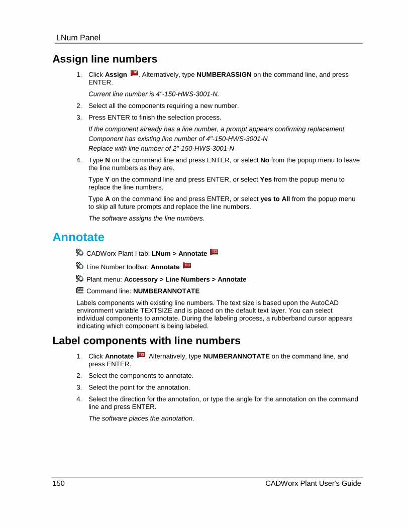
LNum Panel
Assign line numbers 1. Click Assign . Alternatively, type NUMBERASSIGN on the command line, and press
ENTER.
Current line number is 4"-150-HWS-3001-N.
2. Select all the components requiring a new number.
3. Press ENTER to finish the selection process.
If the component already has a line number, a prompt appears confirming replacement. Component has existing line number of 4"-150-HWS-3001-N Replace with line number of 2"-150-HWS-3001-N
4. Type N on the command line and press ENTER, or select No from the popup menu to leave the line numbers as they are.
Type Y on the command line and press ENTER, or select Yes from the popup menu to replace the line numbers.
Type A on the command line and press ENTER, or select yes to All from the popup menu to skip all future prompts and replace the line numbers.
The software assigns the line numbers.
Annotate CADWorx Plant I tab: LNum > Annotate
Line Number toolbar: Annotate
Plant menu: Accessory > Line Numbers > Annotate
Command line: NUMBERANNOTATE
Labels components with existing line numbers. The text size is based upon the AutoCAD environment variable TEXTSIZE and is placed on the default text layer. You can select individual components to annotate. During the labeling process, a rubberband cursor appears indicating which component is being labeled.
Label components with line numbers 1. Click Annotate . Alternatively, type NUMBERANNOTATE on the command line, and
press ENTER.
2. Select the components to annotate.
3. Select the point for the annotation.
4. Select the direction for the annotation, or type the angle for the annotation on the command line and press ENTER.
The software places the annotation.
150 CADWorx Plant User's Guide
LNum Panel
Line CADWorx Plant I tab: LNum > Line
Setting toolbar: Line
Plant menu: Utility > Set Component > Line
Command line: COMP2LINE
Sets the current line number by selecting a component with the required line number. Any components created after running this command use the new line number.
This option requires that you set the LineNumberSystem (on page 41) variable to 2. This is the same as selecting the System On (Static Size/Spec) option in the Line Numbering System dialog box. For more information, see Line Numbering System Dialog Box (on page 146).
Set the current line number to that of a component 1. Click Line . Alternatively, type COMP2LINE on the command line, and press ENTER.
2. Select a component in the drawing.
CADWorx displays the line number.
Line Isolate Plant menu: Utility > Line Isolate
Command line: LINEISOLATE
Isolates components based on their line numbers or their specifications. You can use this command to isolate an entire line number or to isolate one line number and include surrounding buildings or equipment. It can also turn off any isolation of components or surrounding equipment and building.
Isolate - Isolates only components with particular specifications or line numbers. This option hides all objects including non-CADWorx objects in the drawing. To make them visible again, run this command again and select the Show all option.
Partial isolate - Works similar to the Isolate option, except that it leaves the surrounding graphics (building, equipment, dimensions, and so on) visible. This option has the same additional options as Isolate.
Show all - Turns off any isolation and makes all objects in the drawing visible.
Spec - Lists all specs used in the model. You can select one or more specifications to isolate.
Line number - Lists all line numbers used in the drawing. You can select one or more line numbers to isolate.
List - Displays a dialog box listing either the specifications or line numbers within the drawing. You can select one or more items using the standard Windows selection methods.
Select component - Select a component in the drawing.
CADWorx Plant User's Guide 151

LNum Panel
152 CADWorx Plant User's Guide
S E C T I O N 7
CADWorx Plant I tab > Steel BOM DB Panel
Command Description Command line
BOM Setup - Customizes the Bill of Material schedule to any style or layout that you need. For more information, see Bill of Material Setup (on page 154).
BOMSETUP
Cut BOM - Generates a Bill of Material schedule listing each piece of pipe with a length and a tag. For more information, see Cut Pipe Bill of Material (on page 157).
BOMCUT
Total BOM - Generates a Bill of Material schedule with one tag for a total length of pipe in each size. For more information, see Total Pipe Bill of Material (on page 159).
BOMTOTAL
Single BOM - Generates a Bill of Material schedule with each selected object on a line by itself. For more information, see Single Pipe Bill of Material (on page 160).
BOMSINGLE
Export BOM - Exports the steel Bill of Material schedule to an external file format that you specify. For more information, see Export Pipe Bill of Material (on page 162).
BOMEXPORT
Import BOM - Imports a database into a Bill a Material schedule. For more information, see Import Pipe Bill of Material (on page 163).
BOMIMPORT
Delete BOM - Deletes all entities designated for Bill of Material. For more information, see Delete Bill of Material (on page 163).
BOMDELETE
Tag Toggle - Turns on and off the placement of tags. For more information, see Tag Toggle Bill of Material (on page 163).
TAGTOGGLE
Tag Location - Moves a tag. For more information, see Tag Location (on page 163).
TAGRELOCATE
Insert Tag - Places a tag on the drawing without having to run a Bill of Material. For more information, see Insert Tag (on page 164).
TAGINSERT
Setup Live Database - Links the drawing to an external database. For more information, see Setup Live Database (on page 164).
LIVEDB
Pipe BOM / DB Panel
CADWorx Plant User's Guide 153

Pipe BOM / DB Panel
Export Pipe - Exports CADWorx component information to a Microsoft Access or Microsoft Excel file. For more information, see Export Pipe (on page 165).
DBFGEN
Import Pipe - Imports and draws CADWorx components from a Microsoft Access or Microsoft Excel file. For more information, see Import Pipe (on page 168).
DBFIN
Audit Pipe Database - Maintains the database for each component in the drawing that has data attached. For more information, see Audit Pipe Database (on page 168).
DBAUDIT
Synchronize - Checks all components in the drawing and updates them according to the current value in the database. For more information, see Synchronize Pipe Database (on page 169).
SYNC
C.G. Generator - Calculates the center of gravity for selected pipe members. For more information, see C.G. Generator (on page 171).
CG
Bill of Material Setup CADWorx Plant I tab: Pipe BOM / DB > Setup Pipe BOM / DB toolbar: Setup Plant menu: Bill of Material > Setup Command line: BOMSETUP
Customizes the Bill of Material schedule to any style or layout that you need. Using this dialog box, you can specify column widths, provide the schedule direction (up or down), provide user specified headings for columns, allow alignment of columns, and the selection of over 30 different entries into the schedule. You can arrange the columns in any order.
Bill of material lengths are based on DIMLFAC, DIMDEC, and DIMLUNIT.
Use the Tag Toggle Bill of Material (on page 163) command to turn the tags on and off in the schedule.
Bill of Material Setup Dialog Box Defines or edits the Bill of Material (BOM) schedule template. The template is stored in the configuration file listed at the top of the dialog.
Database Columns Available - Lists all the information that you can include in the BOM. These columns can be added to any schedule template in any order using Add.
There are six special columns: USER1, USER2, USER3, USER4, USER5, UNIT. These columns are blank in the BOM. You can manually enter data after the BOM is generated.
Custom Data created in the Specification Editor can be added to any schedule template in any order using Add. Find the custom data field name in the Database Columns Available to add it to BOM Columns Selected.
PT4_X, PT4_Y and PT4 _Z are the world coordinate system location of the approximate center point of the component.
154 CADWorx Plant User's Guide

Pipe BOM / DB Panel BOM Columns Selected - Shows all the columns that have been selected and their order of appearance in the schedule from left (top of list box) to right (bottom of list box). Use Sort Order to set the order by which these columns are sorted.
Add and Remove - Moves selected columns between the Database Columns Available and BOM Columns Selected lists. You can also move a column to the other list by double-clicking the column name in the list.
Alignment - Specifies the text alignment for the selected column.
Grow Direction - Specifies whether the schedule should start at the top and work its way down or start at the bottom and work its way up.
Move Up and Move Down - Defines the column order in the BOM. Select a column in the BOM Columns Selected list, and then click Move Up to place the column further left in the BOM. Click Move Down to place the selected column further right in the BOM.
Move Up and Move Down do not set the sort order of the BOM, only the placement of the columns. Use Sort Order to define the sort order.
Column title - Specifies the text heading for the selected column.
Column width - Specifies the width for the selected column.
Sort Order - Controls the sort order and accumulation of pipe components in the BOM. For more information, see BOM Sort Order / Accumulation Dialog Box (on page 157).
What do you want to do? Add or remove properties from BOM (on page 155)
Change the column order (on page 156)
Change text alignment in columns (on page 156)
Change the BOM sorting and accumulation (on page 156)
Add or remove properties from BOM 1. On the Pipe BOM / DB panel, click Setup .
You can also type BOMSETUP in the command line.
The Bill of Material Setup dialog box displays.
2. To add a property to the BOM, double-click the property in the Database Columns Available list.
Use the Column title and Column width boxes to define the column heading text and the column width respectively.
3. To remove a property from the BOM, double-click the property in the BOM Columns Selected list.
4. Click OK.
CADWorx Plant User's Guide 155
Pipe BOM / DB Panel
Change the column order 1. On the Pipe BOM / DB panel, click Setup .
You can also type BOMSETUP in the command line.
The Bill of Material Setup dialog box displays.
2. Select the column to move in the BOM Columns Selected list.
3. Use Move Up and Move Down to change the column order. The column order in the list top to bottom is the column order in the BOM from left to right.
4. Click OK.
Change text alignment in columns 1. On the Pipe BOM / DB panel, click Setup .
You can also type BOMSETUP in the command line.
The Bill of Material Setup dialog box displays.
2. Select the column to edit in the BOM Columns Selected list.
3. Select Left, Center, or Right to control the vertical text justification in the selected column.
4. Select Downward or Upward to control the horizontal alignment of the text in the selected column.
5. Click OK.
Change the BOM sorting and accumulation 1. On the Pipe BOM / DB panel, click Setup .
You can also type BOMSETUP in the command line.
The Bill of Material Setup dialog box displays.
2. Click Sort Order.
The BOM Sort Order / Accumulation Control Setup dialog box displays.
3. Move the columns that you want to sort with to the BOM Columns Selected list.
4. Use Move Up and Move Down to specify which columns are sorted first in the BOM.
5. Select a column and use the Ascending and Descending options to control how information in that column is sorted. Ascending means sorting from small numbers to larger numbers (1 to 100) and from A to Z. Descending is large number to smaller (100 to 1) and Z to A.
6. Click OK on the BOM Sort Order dialog box.
7. Click OK on the Bill of Material Setup dialog box.
156 CADWorx Plant User's Guide

Pipe BOM / DB Panel
BOM Sort Order / Accumulation Dialog Box Controls the sort order of the BOM. Columns that you place in the BOM Columns Selected list are used to sort the BOM starting with the top column, then the second column, and so forth. Use Move Up and Move Down to change the order in which the BOM is sorted.
This dialog box also controls the accumulation of piping components. If two valves have different TAG values and you do not want these to accumulate, then you need to add TAG to the BOM Columns Selected list.
Database Columns Available - Lists all the information on a steel member that you can use to sort the BOM. These columns can be used to sort using Add.
BOM Columns Selected - Shows all the columns that have been selected for sorting and their sort order from top to bottom.
Add and Remove - Moves selected columns between the BOM Columns Available and BOM Columns Selected lists. You can also move a column to the other list by double-clicking on the column name in the list.
Column Sort - Controls additional sorting on each selected column.
Ascending - Sorts from small numbers to larger numbers (1 to 100) and from A to Z.
Descending - Sorts from large numbers to small numbers (100 to 1) and from Z to A.
If you want the BOM to sort from large size piping to small size piping, use Descending for MAIN_NOM and RED_NOM.
Move Up and Move Down - Defines the sort order in the BOM. Select a column in the BOM Columns Selected list, and then click Move Up to sort that column before other columns. Click Move Down to sort the column after columns higher in the list.
When you add the line number (LINE_NUM) to BOM Columns Selected, the bill of material export options (BOMCUT, BOMTOTAL, and BOMEXPORT) calculates the components by the line number rather than the total number of the selected components.
Cut Pipe Bill of Material CADWorx Plant I tab: Pipe BOM / DB > Cut
Pipe BOM / DB toolbar: Cut
Plant menu: Bill of Material > Run > Cut
Command line: BOMCUT
Generates a Bill of Material schedule listing each piece of pipe with a length and a tag. Identical items are accumulated in the quantity column.
Bill of material lengths are based on DIMLFAC, DIMDEC, and DIMLUNIT.
Counter - Select this option to start the tag counter at any positive nonzero integer. When set, the command resumes requesting that you pick Manual placement or Automatic placement of tags.
Manual placement - Select to insert tags manually. You are prompted for the tag location. The software adds a rubber band line attached to the component extending to the specified tag location. You must continue specifying locations until the last component’s tag has been placed.
CADWorx Plant User's Guide 157
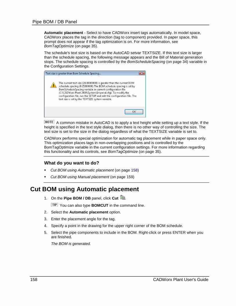
Pipe BOM / DB Panel Automatic placement - Select to have CADWorx insert tags automatically. In model space, CADWorx places the tag in the direction (tag to component) provided. In paper space, this prompt does not appear if the tag optimization is on. For more information, see BomTagOptimize (on page 35).
The schedule's text size is based on the AutoCAD setvar TEXTSIZE. If this text size is larger than the schedule spacing, the following message appears and the Bill of Material generation stops. The schedule spacing is controlled by the BomScheduleSpacing (on page 34) variable in the Configuration Settings.
A common mistake in AutoCAD is to apply a text height while setting up a text style. If the
height is specified in the text style dialog, then there is no other way of controlling the size. The text size is set to the size in the dialog regardless of what the TEXTSIZE variable is set to.
CADWorx performs special optimization for automatic tag placement while in paper space only. This optimization places tags in non-overlapping positions and is controlled by the BomTagOptimize variable in the current configuration settings. For more information regarding this functionality and its controls, see BomTagOptimize (on page 35).
What do you want to do? Cut BOM using Automatic placement (on page 158)
Cut BOM using Manual placement (on page 159)
Cut BOM using Automatic placement 1. On the Pipe BOM / DB panel, click Cut .
You can also type BOMCUT in the command line.
2. Select the Automatic placement option.
3. Enter the placement angle for the tag.
4. Specify a point in the drawing for the upper right corner of the BOM schedule.
5. Select the pipe components to include in the BOM. Right-click or press ENTER when you are finished.
The BOM is generated.
158 CADWorx Plant User's Guide
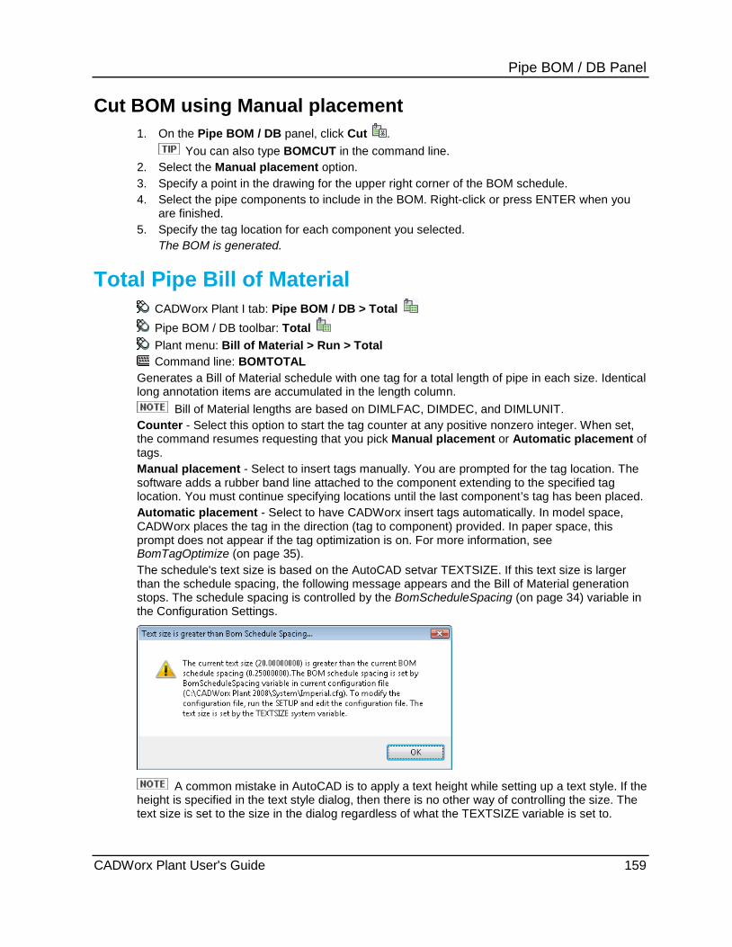
Pipe BOM / DB Panel
Cut BOM using Manual placement 1. On the Pipe BOM / DB panel, click Cut .
You can also type BOMCUT in the command line. 2. Select the Manual placement option. 3. Specify a point in the drawing for the upper right corner of the BOM schedule. 4. Select the pipe components to include in the BOM. Right-click or press ENTER when you
are finished. 5. Specify the tag location for each component you selected.
The BOM is generated.
Total Pipe Bill of Material CADWorx Plant I tab: Pipe BOM / DB > Total Pipe BOM / DB toolbar: Total Plant menu: Bill of Material > Run > Total Command line: BOMTOTAL
Generates a Bill of Material schedule with one tag for a total length of pipe in each size. Identical long annotation items are accumulated in the length column.
Bill of Material lengths are based on DIMLFAC, DIMDEC, and DIMLUNIT. Counter - Select this option to start the tag counter at any positive nonzero integer. When set, the command resumes requesting that you pick Manual placement or Automatic placement of tags. Manual placement - Select to insert tags manually. You are prompted for the tag location. The software adds a rubber band line attached to the component extending to the specified tag location. You must continue specifying locations until the last component’s tag has been placed. Automatic placement - Select to have CADWorx insert tags automatically. In model space, CADWorx places the tag in the direction (tag to component) provided. In paper space, this prompt does not appear if the tag optimization is on. For more information, see BomTagOptimize (on page 35). The schedule's text size is based on the AutoCAD setvar TEXTSIZE. If this text size is larger than the schedule spacing, the following message appears and the Bill of Material generation stops. The schedule spacing is controlled by the BomScheduleSpacing (on page 34) variable in the Configuration Settings.
A common mistake in AutoCAD is to apply a text height while setting up a text style. If the
height is specified in the text style dialog, then there is no other way of controlling the size. The text size is set to the size in the dialog regardless of what the TEXTSIZE variable is set to.
CADWorx Plant User's Guide 159

Pipe BOM / DB Panel CADWorx performs special optimization for automatic tag placement while in paper space only. This optimization places tags in non-overlapping positions and is controlled by the BomTagOptimize variable in the current configuration settings. For more information regarding this functionality and its controls, see BomTagOptimize (on page 35).
What do you want to do? Total BOM using Automatic placement (on page 160)
Total BOM using Manual placement (on page 160)
Total BOM using Automatic placement 1. On the Pipe BOM / DB panel, click Total .
You can also type BOMTOTAL in the command line.
2. Select the Automatic placement option.
3. Enter the placement angle for the tag.
4. Specify a point in the drawing for the upper right corner of the BOM schedule.
5. Select the pipe components to include in the BOM. Right-click or press ENTER when you are finished.
The BOM is generated.
Total BOM using Manual placement 1. On the Pipe BOM / DB panel, click Total .
You can also type BOMTOTAL in the command line.
2. Select the Manual placement option.
3. Specify a point in the drawing for the upper right corner of the BOM schedule.
4. Select the pipe components to include in the BOM. Right-click or press ENTER when you are finished.
5. Specify the tag location for each component you selected.
The BOM is generated.
Single Pipe Bill of Material CADWorx Plant I tab: Pipe BOM / DB > Single
Pipe BOM / DB toolbar: Single
Plant menu: Bill of Material > Run > Single
Command line: BOMSINGLE
Generates a Bill of Material schedule with each selected object having its own line in the schedule.
Bill of material lengths are based on DIMLFAC, DIMDEC, and DIMLUNIT.
160 CADWorx Plant User's Guide
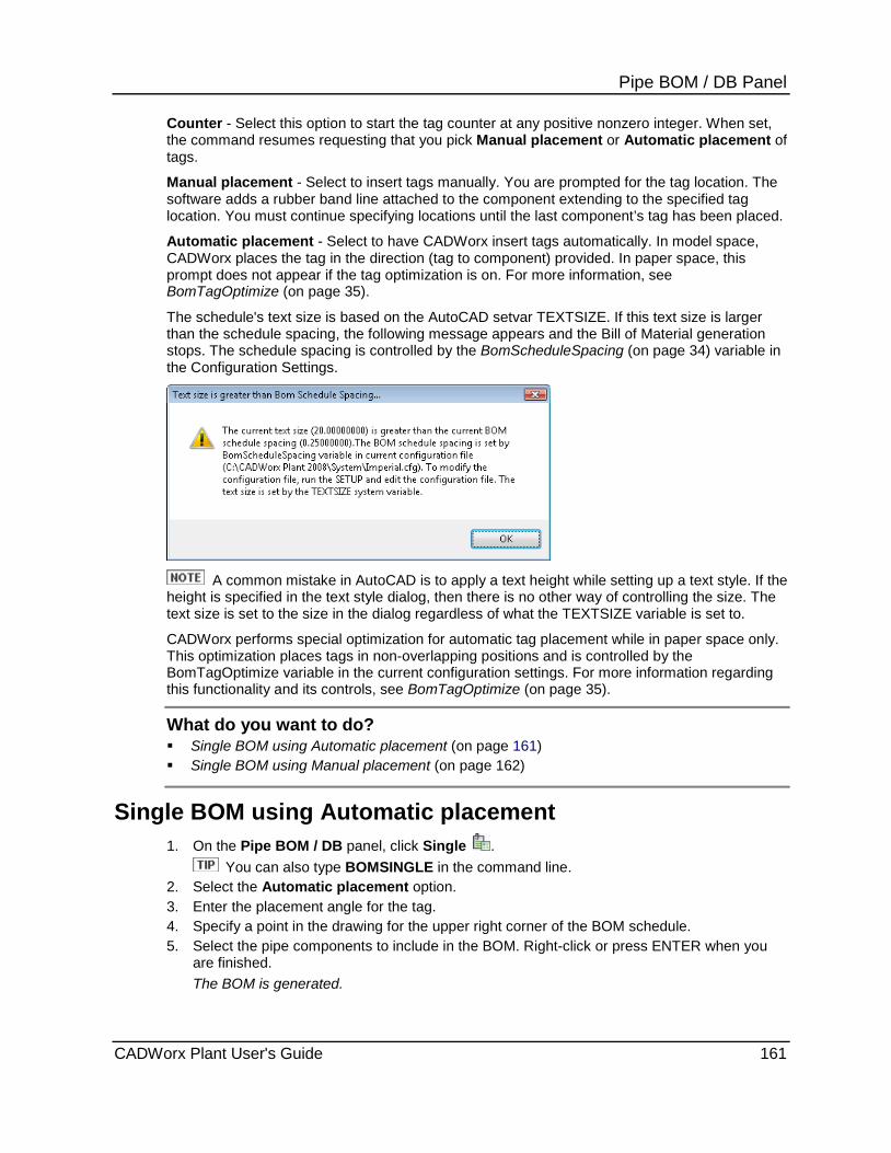
Pipe BOM / DB Panel Counter - Select this option to start the tag counter at any positive nonzero integer. When set, the command resumes requesting that you pick Manual placement or Automatic placement of tags.
Manual placement - Select to insert tags manually. You are prompted for the tag location. The software adds a rubber band line attached to the component extending to the specified tag location. You must continue specifying locations until the last component’s tag has been placed.
Automatic placement - Select to have CADWorx insert tags automatically. In model space, CADWorx places the tag in the direction (tag to component) provided. In paper space, this prompt does not appear if the tag optimization is on. For more information, see BomTagOptimize (on page 35).
The schedule's text size is based on the AutoCAD setvar TEXTSIZE. If this text size is larger than the schedule spacing, the following message appears and the Bill of Material generation stops. The schedule spacing is controlled by the BomScheduleSpacing (on page 34) variable in the Configuration Settings.
A common mistake in AutoCAD is to apply a text height while setting up a text style. If the
height is specified in the text style dialog, then there is no other way of controlling the size. The text size is set to the size in the dialog regardless of what the TEXTSIZE variable is set to.
CADWorx performs special optimization for automatic tag placement while in paper space only. This optimization places tags in non-overlapping positions and is controlled by the BomTagOptimize variable in the current configuration settings. For more information regarding this functionality and its controls, see BomTagOptimize (on page 35).
What do you want to do? Single BOM using Automatic placement (on page 161) Single BOM using Manual placement (on page 162)
Single BOM using Automatic placement 1. On the Pipe BOM / DB panel, click Single .
You can also type BOMSINGLE in the command line. 2. Select the Automatic placement option. 3. Enter the placement angle for the tag. 4. Specify a point in the drawing for the upper right corner of the BOM schedule. 5. Select the pipe components to include in the BOM. Right-click or press ENTER when you
are finished. The BOM is generated.
CADWorx Plant User's Guide 161
Pipe BOM / DB Panel
Single BOM using Manual placement 1. On the Pipe BOM / DB panel, click Single .
You can also type BOMSINGLE in the command line.
2. Select the Manual placement option.
3. Specify a point in the drawing for the upper right corner of the BOM schedule.
4. Select the pipe components to include in the BOM. Right-click or press ENTER when you are finished.
5. Specify the tag location for each component you selected.
The BOM is generated.
Export Pipe Bill of Material CADWorx Plant I tab: Pipe BOM / DB > Export
Pipe BOM / DB toolbar: Export
Plant menu: Bill of Material > Export
Command line: BOMEXPORT
Exports the steel Bill of Material schedule to an external file format that you specify. The schedule for the Bill of Material is defined using Bill of Material Setup (on page 154). CADWorx can export the Bill of Material schedules to:
Access file (*.mdb) Excel file (*.xls) Text file (*.txt) HTML file (*.htm)
When exporting data to Microsoft Excel, numeric data is exported as text and is preceded by a single quote. This single quote prevents you from totaling the column in Excel. To correct this in Excel, select the column and then select Data > Text To Columns. Step through the wizard selecting the Delimited option and Tab as the Delimiter check box. This changes the data from text to numbers. In Imperial/Inch settings, length is exported in feet and inches, which cannot be totaled in Excel. To export length in decimal format, change the current AutoCAD Dimension Style settings Primary Units format to decimal.
An additional command called BOMEXTERNAL is available to export a project database to a file based on the columns chosen in the BOMSETUP.
1. On the Pipe BOM / DB panel, click Export .
You can also type BOMEXPORT in the command line.
2. Specify if you want a Cut, Total, or Single BOM.
3. Select the objects to include in the BOM. Right-click or press ENTER when you are finished.
4. In the Save as type box, select the file format that you want.
5. Type the file name, and specify the folder location.
6. Click Save.
162 CADWorx Plant User's Guide

Pipe BOM / DB Panel
Import Pipe Bill of Material Plant menu: Bill of Material > Import
Command line: BOMIMPORT
Imports a database into a Bill of Material schedule on the present drawing. The schedule is generated using the BOMSETUP parameters, see Bill of Material Setup (on page 154). You can import only Access files (*.mdb) formats created with the DBFGEN command. For more information, see Export Pipe (on page 165).
This command cannot be used to import data from the files generated with the BOMEXPORT command because BOMEXPORT exports only partial field information. BOMIMPORT command expects all the fields to be present.
1. Select Plant > Bill of Material > Import. You can also type BOMIMPORT in the command line.
2. Specify if you want a Cut length, Total length, or Single item BOM. 3. Select to use the current database or to select another database. The current database
displays in the command line area. 4. Select the upper right corner location of the Bill of Material in the drawing.
Delete Bill of Material Plant menu: Bill of Material > Delete Command line: BOMDELETE
Deletes all entities that are on the layer designated for Bill of Materials in the current configuration settings. This option cannot be used for deleting partial tags or for deleting the schedule only. 1. Select Plant > Bill of Material > Delete.
You can also type BOMDELETE in the command line.
Tag Toggle Bill of Material Plant menu: Bill of Material > Tag > Toggle Command line: TAGTOGGLE
Toggle Bill of Material tags in the schedule on and off. 1. Select Plant > Bill of Material > Tag > Toggle.
You can also type TAGTOGGLE in the command line.
Tag Location Plant menu: Utilities > Nozzle Schedule > Tag > Location
Command line: TAGRELOCATE (EQUIPTAGRELOCATE in CADWorx Equipment)
Relocates a tag. This command is useful when tags are placed on top of each other. Optionally, this command deletes the connector line from the item mark to the component. This is useful when multiple items are required for one location, such as gaskets and bolts associated with a flange.
Tags and the associated leader lines are grouped. This makes them easier to manipulate. You can use the AutoCAD Group command to un-group the items and manually rearrange them.
CADWorx Plant User's Guide 163

Pipe BOM / DB Panel
Insert Tag Plant menu: Utilities > Nozzle Schedule > Tag > Insert
Command line: TAGINSERT (EQUIPTAGINSERT in CADWorx Equipment)
Places tags on the drawing without having to run the main Bill of Material generator. The tag is scaled according to the present text size.
Setup Live Database CADWorx Plant I tab: Pipe BOM / DB > Setup
Pipe BOM / DB toolbar: Setup
Plant menu: Accessory > Database > Setup
Command line: LIVEDB
CADWorx supports a fully functional live external database. Use this command to define the database settings that are saved to the configuration file listed. When a drawing is opened and a configuration file is located in the same folder, the drawing initializes according to that configuration file using a live database or not.
When a component is deleted from the drawing and there is a live database active, that
component is marked for deletion in the database. When the drawing is closed, if the drawing is not saved the item is not deleted from the database. If the drawing is saved, then the item is deleted from the database.
When a component or a group of components are copied from a drawing to a new drawing that uses the same live database, the copied components are duplicated in the live database with the new drawing name.
When a component or a group of components are cut from a drawing and placed in another drawing that uses the same live database, the components duplicate in the live database with the new drawing name. When the old drawing is saved and closed any duplicate items from the first drawing are deleted from the live database because they are no longer on the first drawing.
All changes to live database settings take effect in the next drawing session.
On/Off - Turns the live database system on and off. When on, all components drawn are updated instantaneously to the database. Changes can be made in the drawing or in the database. When off, all CADWorx component information is stored only within the drawing.
Database Type - Select the type of database to use as the live database. Depending on the type chosen, the path to the database or schema is displayed.
Access Path - Defines the Microsoft Access database information. Click Create Table to create the PIPE table in the database when creating a new database. Click Select File to specify an existing database.
SQL Server Database Name and Schema - Defines the Microsoft SQL Server database information. You must have already created the ODBC schemas (refer to the installation guide for help). Type the database name in the Database box. Type the ODBC schema name in the Schema box, either Plant_SQL_SERVER or Steel_SQL_SERVER.
164 CADWorx Plant User's Guide

Pipe BOM / DB Panel Oracle Schema - Defines the Oracle database information. Type the ODBC schema name in the Schema box.
Startup Dialog Options - Sets the database option on CADWorx startup.
No dialog (new drawings are in Live DB) - Select to place new drawings automatically in the database. Selecting this option requires that a new drawing be named and saved immediately on creation. Drawings that use a live database must be in the same folder with the appropriate configuration file.
No dialog (new drawings are not in Live DB) - Select to not add new drawings to the database. You can add drawings to the live database later using this command.
Show dialog - Select to display a dialog box on which you can choose to use a database or not.
Existing components in drawings can be added to the database by using DBFGEN for Pipe or SDBFGEN for Steel. For more information, see Export Pipe (on page 165).
Enter User Name and Password Dialog Box Enables you to access the system by entering a user name and password when required.
User Name - Specifies your user name for the system.
Password - Type the password, if your system requires a password.
Database : Schema - Displays the database name and schema from the Enter Value dialog box. For Oracle, only the schema displays from the Enter Schema dialog box.
Export Pipe CADWorx Plant I tab: Pipe BOM / DB > Export
Pipe BOM / DB toolbar: Export
Plant menu: Accessory > Database > Export
Command line: DBFGEN
Exports CADWorx component information to a Microsoft Access or Microsoft Excel file.
When using live database, this command updates the appropriate database setup for the drawing.
Database Type - Select Access to write to a Microsoft Access file, or select Excel to write to a Microsoft Excel file.
Browse - Click to define the file name and folder location. The disabled boxes at the bottom of the dialog display the file name and folder in use.
Append/Sync - Synchronizes the drawing and the database file by removing entries from the database that no longer exist in the drawing and updating components in the database according to the drawing. You can use this command once a day or five times an hour to maintain the database according to the drawing. Many users can append to the same database file at the same time.
New - Creates a new database file based on the chosen folder and database type.
CADWorx Plant User's Guide 165

Pipe BOM / DB Panel 1. On the Pipe BOM / DB panel, click Export .
You can also type DBFGEN in the command line.
Enter an option [Line number/Select component] <Select component>.
2. Select Line Number to select components using line numbers.
Enter an option [List/Select component] <Select component>.
3. Choose List to select the line number from a list. For more information, see Select Item Dialog Box (on page 166).
or
Choose Select component to select the needed components by crossing, window, or any other preferred method.
4. Select the components to write to the database file. Right-click or press ENTER when you are finished.
The Select Database Type dialog box displays.
5. Select Access or Excel to define the file type.
6. Click Browse, and define the folder and file name.
7. Select New if you are creating a new file.
or
Select Append/Sync if you want to synchronize an existing file.
8. Click OK.
If live database is being used, the prompt Continue to update live database? [Yes/No] <Yes>: displays.
9. Click Yes to update the database.
or
Click No to stop updating the live database.
Select Item Dialog Box Lists all the line number or specifications in the drawing (or database). You can select multiple items using the CTRL or SHIFT keys.
Filter - Enter a wildcard filter to limit the items available in the list. The filter is case sensitive.
Wildcards
Character Used to
# (pound) Matches any single numeric digit
@ (at) Matches any single alphabetic character
. (period) Matches any single non-alphanumeric character
166 CADWorx Plant User's Guide

Pipe BOM / DB Panel * (asterisk) Matches any character sequence, including an empty one, and it can
be used anywhere in the search pattern: beginning, middle, or end
? (question mark) Matches any single character
~ (tilde) If it is the first character in the pattern, it matches anything except the pattern
[...] Matches any one of the characters enclosed
[~...] Matches any single character not enclosed
- (hyphen) Used inside brackets to specify a range for a single character
, (comma) Separates two patterns
` (reverse quote) Escapes special characters (reads next character literally)
In the example below, lines with 2C or A1 display for selection.
CADWorx Plant User's Guide 167
Pipe BOM / DB Panel
Import Pipe CADWorx Plant I tab: Pipe BOM / DB > Import
Pipe BOM / DB toolbar: Import
Plant menu: Accessory > Database > Import
Command line: DBFIN
Imports and draws CADWorx components from a Microsoft Access or Microsoft Excel file. This command is not available when you are using a live database.
You can select one or more drawings to import. CADWorx then draws the imported components in single line mode. These can be converted to any other modes using the Mode Convert (on page 81) tools available.
1. On the Pipe BOM / DB panel, click Import .
You can also type DBFIN in the command line. The Select Database File dialog box displays.
2. Browse to and select the file to import. 3. Click Open.
The Select Item dialog box displays. 4. Select the drawings in the file to import into the active drawing. 5. Click OK.
Audit Pipe Database CADWorx Plant I tab: Pipe BOM / DB > Audit
Pipe BOM / DB toolbar: Audit
Plant menu: Accessory > Database > Audit
Command line: DBAUDIT
Maintains the database for each component in the drawing that has data attached. Use this command whenever the drawing or the database has any problems. If a problem is found in the drawing, for example a component in the database is not present in the drawing, you have the option to delete this component in the database or to simply ignore it.
1. On the Pipe BOM / DB panel, click Audit .
You can also type DBAUDIT in the command line.
The Select Database File dialog box displays.
2. Browse to and select the file to audit against the drawing.
3. Click Open.
The message Checking objects in this drawing with rows in the database displays.
4. If no problems are found, the message Audit completed displays.
5. If a problem is found, you are prompted to delete the row from the database. Select Yes to delete the row. Select No to ignore the row.
168 CADWorx Plant User's Guide
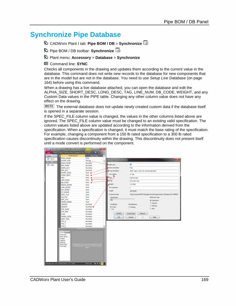
Pipe BOM / DB Panel
Synchronize Pipe Database CADWorx Plant I tab: Pipe BOM / DB > Synchronize
Pipe BOM / DB toolbar: Synchronize
Plant menu: Accessory > Database > Synchronize Command line: SYNC
Checks all components in the drawing and updates them according to the current value in the database. This command does not write new records to the database for new components that are in the model but are not in the database. You need to use Setup Live Database (on page 164) before using this command. When a drawing has a live database attached, you can open the database and edit the ALPHA_SIZE, SHORT_DESC, LONG_DESC, TAG, LINE_NUM, DB_CODE, WEIGHT, and any Custom Data values in the PIPE table. Changing any other column value does not have any effect on the drawing.
The external database does not update newly created custom data if the database itself is opened in a separate session. If the SPEC_FILE column value is changed, the values in the other columns listed above are ignored. The SPEC_FILE column value must be changed to an existing valid specification. The column values listed above are updated according to the information derived from the specification. When a specification is changed, it must match the base rating of the specification. For example, changing a component from a 150 lb rated specification to a 300 lb rated specification causes discontinuity within the drawing. This discontinuity does not present itself until a mode convert is performed on the component.
CADWorx Plant User's Guide 169
Pipe BOM / DB Panel After data is changed and you run Synchronize , the data is updated. The Synchronize command now works in conjunction with the SyncOnStartUp (on page 44) variable in Configuration Settings (on page 31). Setting the SyncOnStartUp variable to Synchronize With Changes Review displays the Synchronize Component dialog box that enables you to review the changes made to a database and decide which ones to accept or reject. These changes also include the custom data fields created in the Specification Editor.
Synchronize Component Dialog Box Enables you to review the changes made in a live database and accept or reject the changes. The Field Name includes information from the Component Edit dialog box including the custom data. For more information, see Local Edit (on page 70).
Field Name - Specifies the database information name, as they pertain to the database and the corresponding information in the Component Edit dialog box fields. When SyncOnStartUp (on page 44) is set to Synchronize With Changes Review while using a live database, the editable boxes in the Component Edit dialog box display for review in this window. You can then update the changes in the Synchronize Component dialog box, by clicking Accept Changes.
Database Values - Specifies the changed information value for the Field Name when a change was made. If no change was made, the Database Values keep the same value as the Component Values indicating no change takes place when the changes are accepted.
Component Values - Specifies the original database information values for the Field Name.
Field Name, Database Values, and Component Values display in red when a change has been made to the database.
select / deselect all - Enables you to select or clear all changes made to the database.
Accept Changes - Accepts the selected changes made to the database and updates the Component Edit dialog box.
Reject Changes - Rejects the changes to the database and returns them to their original value.
Each component changed displays the Synchronize Component dialog box separately. You must except or reject each change individually.
1. On the Pipe BOM / DB panel, click Synchronize .
You can also type SYNC in the command line.
2. Click Yes to confirm that you want to synchronize the drawing with the database.
OR
The Synchronize Component dialog box displays.
Review the information, and accept or reject the changes.
If you reject the changes, the changes you made in the database file are reset to the previous information.
170 CADWorx Plant User's Guide
Pipe BOM / DB Panel
C.G. Generator CADWorx Plant I tab: Pipe BOM / DB > C.G. Generator
Plant menu: Accessory > C.G. Generator
Command line: TCG
Calculates center of gravity for all components drawn in X,Y planes (2D plans) or in X,Y,Z planes (3D Model). You can use a generic attach (from Plant > Toolbars > Misc) which provides the center of gravity location and weight. For more information on specifying a center of gravity location for a generic attach, see Generic Attach (on page 202) or Steel - Generic Attachment (on page 295).
Selection can be done by crossing, window, or selecting individual component.
Total Center of Gravity Calculation Dialog Box Calculates the total center of gravity for all components.
Selected Components Select - Enables you to select items to calculate the total center of gravity for that item.
Piping - Enables piping to be calculated for the total center of gravity. Reports the selected component counters in the corresponding box.
Piping Insulation - Enables piping insulation to be calculated for the total center of gravity. Reports the selected component counters in the corresponding box.
Steel - Enables steel to be calculated for the total center of gravity. Reports the selected component counters in the corresponding box.
HVAC - Enables HVAC to be calculated for the total center of gravity. Reports the selected component counters in the corresponding box.
Equipment - Enables equipment to be calculated for the total center of gravity. Reports the selected component counters in the corresponding box.
You must have a material set for the equipment, and then run EQUIPCG before you can get a center of gravity calculation for equipment in CADWorx Plant.
Report Options Title - Specifies a title for the report that prints when CG is calculated.
Path - Specifies the location of the report file. Click the Path ellipsis to change the location and save the file.
Print report to command line - Prints the total center of gravity report to the command line.
View Report - Indicates that the software opens the report after the center of gravity calculates.
Insert drawing marker - Inserts a drawing marker for the total center of gravity.
1. Click C.G. Generator on the Pipe BOM / DB panel in the CADWorx Plant I tab. Alternatively, type TCG on the command line and then press ENTER.
The Total CG Calculation dialog box displays.
2. Select the type of components to calculate center of gravity.
CADWorx Plant User's Guide 171

Pipe BOM / DB Panel 3. Enter a title for the report in the Title box.
4. Select whether you want the report to print on the command line, view the report, or whether you want to insert a marker.
5. Click Select.
Before you can get a center of gravity calculation for equipment in CADWorx Plant, you
must have a material set for the equipment, and then you must run EQUIPCG.
When selecting equipment to calculate the center of gravity, you have the following choices:
Select all.
Zoom to the small white cross and select it.
6. Select the components, and then press ENTER.
The center of gravity calculates and the Total CG Calculation dialog box redisplays with the selected component counters in the corresponding boxes.
7. Click OK.
A center of gravity reference point and a report display.
172 CADWorx Plant User's Guide

S E C T I O N 8
CADWorx Plant I tab: Misc
Command Name Command Line
Auto Connect - Turns automatic connection on or off. For more information, see Auto Connect (on page 174).
CONNECTOG
Group On/Off - Turns on or off the grouping of the centerline of the component with the accompanying graphics. For more information, see Group On/Off (on page 175).
GROUPTOG
Weld Size - Sets the default size of the weld dots that accompany single line components. For more information, see Weld Size (on page 175).
WELDSIZE
Join Pipe - Changes segmented piping to non-segmented piping. For more information, see Join Pipe (on page 175).
JOINPIPE
Create - Creates symmetrical or non-symmetrical user shape components. For more information, see User Shapes (on page 176).
USERCREATE
Top Works Add - Adds top works to a valve already drawn in the model. For more information, see Top Works Add (on page 197)
TOPWORKSADD
Top Works Change - Changes the orientation of or deletes top works already associated with a valve. For more information, see Top Works Change (on page 198).
TOPWORKSCHANGE
System Out - Creates a CAESAR II input file. For more information, see System Out (on page 198).
C2OUT
Break Pipe - Changes non-segmented piping to segmented piping. For more information, see Break Pipe (on page 200).
BREAKPIPE
Nozzle Generic Attach - Attaches nozzle information to any generic AutoCAD object in the drawing. For more information, see Nozzle Generic Attach (on page 200).
ENGENERIC
Generic Attach - Attaches information to any generic AutoCAD object in the drawing. For more information, see Generic Attach (on page 202).
GENERIC
System In - Reads a CAESAR II input file. For more information, see System In (on page 206).
C2IN
Change Elevation - Changes the elevation of a selected pipe in the drawing. For more information, see Change Elevation (on page 207).
CHANGEELEVATION
Misc Panel
CADWorx Plant User's Guide 173

Misc Panel Elbow Centerline - Turns on or off elbow centerlines for
use with isometrics. For more information, see Elbow Centerline (on page 209).
ELBOWCL
ISO Flag - Sets a flag in the component indicating that the present stored length should be used regardless of what type of length modifications are made to the pipe component. For more information, see ISO Flag (on page 210).
ISOFLAG
Dim Adjustment - Adjusts a dimension when the pipe segments of a particular run have been adjusted or modified with the ISO flag command. For more information, see Dim Adjustment (on page 208).
DIMADJUST
Re-associate the Components - Enables you to re-associate disconnected components. For more information, see Re-associate the Components (on page 210).
REASSOCIATEMODEL
System Visibility - Turns on or off visibility of components usually located on the system layer. For more information, see System Visibility (on page 210).
SYSVIS
Auto Connect CADWorx Plant I tab: Misc > Auto Connect
Plant menu: Utility > Drawing Control > Auto Connect
Settings toolbar:
Command line: CONNECTTOG
Turns automatic connection on or off. Auto connection provides minimum prompts and makes certain assumptions.
The last component placed in the drawing provides the starting point for the next component. The direction of the last component indicates the direction of the new component.
If you select a component which requires a second direction, such as an elbow, or tee, there are additional prompts requesting the direction.
Typical elbow - Prompts you for a direction.
Pipe with an arbitrary length - Prompts you for an end point.
Elbow pointing up or down - Prompts you for a direction.
This is useful for placing components down a line. It can dramatically decrease the time required to place components in assemblies, such as control valve bypass loops.
If you have run any type of mode conversion, the last point is not available. The software prompts you to pick the starting point.
Auto Connect does not work in conjunction with Router (on page 225).
174 CADWorx Plant User's Guide

Misc Panel
Group On/Off CADWorx Plant I tab: Misc > Group On/Off
Plant menu: Utility > Drawing Control > Group On/Off
Settings toolbar:
Command line: GROUPTOG
Turns on or off the grouping of the centerline of the component with the accompanying graphics. This is useful for selecting any piece of the component rather than only the centerline. By default, grouping is turned on.
Weld Size CADWorx Plant I tab: Misc > Weld Size
Plant menu: Utility > Drawing Control > Weld Size
Command line: WELDSIZE
Specifies the default size of the weld dots that accompany single line components. This command also allows for the change of weld dots already placed in the drawing.
Specify the weld dot size for a single line pipe 1. Click Weld Size . Alternatively, type WELDSIZE on the command line, and press
ENTER.
2. Type the new weld size on the command line, and press ENTER.
The software changes the weld dot size.
Join Pipe CADWorx Plant I tab: Misc > Join Pipe
Command line: JOINPIPE
Changes segmented piping to non-segmented piping.
Run - Joins the entire run of pipe.
Segment - Joins the selected segments of pipe.
What do you want to do? Join by Run (on page 176)
Join by Segment (on page 176)
CADWorx Plant User's Guide 175

Misc Panel
Join by Run 1. Click Join Pipe on the Misc panel in the CADWorx Plant I tab.
2. Type R on the command line, and then press ENTER.
3. Select the pipe to join.
The software joins all segments along the selected piping.
The JOINPIPE command for the Run option does not work around elbows. To join the piping on the other side of the elbow select it during step 3.
Join by Segment 1. Click Join Pipe on the Misc panel in the CADWorx Plant I tab.
2. Type S on the command line, and then press ENTER.
3. Select the segments to join.
The software joins the selected segments.
User Shapes CADWorx Plant I tab: Misc > Create Misc toolbar: Create Command line: USERCREATE
Creates symmetrical or nonsymmetrical user shape components. Symmetrical shapes require you to draw an outline that can be used to create the user component. Non-symmetrical shapes require a block or an object completely drawn in 2D and 3D that represents the complete component. A symmetrical object can be converted from 2D to 3D Mode, or vice versa, using the mode convert (on page 81) commands. It does not allow double-line to single-line conversion in 2D mode. Non-symmetrical shapes can only convert between isometric and solids (Convert Isometric (on page 82) or 3D Solids (on page 82)). 1. Create the component. 2. Modify the specification. 3. Click Create , or type USERCREATE on the command line and press ENTER.
The Define User Shape dialog box displays. Each dialog box option is explained below.
User shape components can also be tagged as optional components in the specification. This allows for an infinite number of additional components.
For symmetrically shaped components, draw a 2D polyline indicating the outline of the shape. The symmetrical shape is limited to straight lines between vertices in the polyline. In other words, there cannot be a fillet radius on any corner of the polyline. If fillets exist, the routine draws them with chamfered corners. Draw only half of the shape on one side of the centerline. We recommend preparing an outline before trying to draw the polyline. For example, draw the component using standard AutoCAD methods or CADWorx components, and then draw a polyline around the contour.
For symmetrical shapes, the polyline may overlap as shown in the example below for 2D solids (drawn to each indicated point, PT1, PT2, and so on). For use with 3D solids, the polyline cannot overlap (there cannot be a PT4 or PT7). If the polyline overlaps, an ACIS error occurs indicating the object cannot be revolved.
176 CADWorx Plant User's Guide

Misc Panel For non-symmetrically shaped components, you must first create a 2D and 3D representation. This representation needs to show all the required details of the component. The 3D representation is used when in the 3D drawing mode. It can be used for orthographic and model-type representation. The 2D representation is used when in the 2D isometric drawing mode.
After the polyline or components are complete, click Create . This creates a data file in the required folder with the required file name. For non-symmetrically shaped components, it also creates two drawing files: one 2D and one 3D. The drawing names have appended in square brackets, the size and drawing mode (for example, [4.0-3D]). The file name must be unique. User Shapes are stored in Product Folder]\Plant\Spec. You can change were User Shapes are stored under Folder Setting in the Define User Shape dialog box.
Make sure to set a default size and specification first. Create must be run multiple times for creating components with different sizes.
Component Setup Name - Specifies the name of the user shape. There is a 20 character limit. Number - Specifies the number of the user shape. Select a number in the range of 1 to 5. Specification - Sets the specification for the user shape. Assign to Spec - Assigns the user shape to other specifications. Save to Catalog - Saves the user shape to the catalog. Folder Settings Folder - Defines the save location for the user shape. Browse - Enables you to search the computer folders for a specific location. Define Size and Geometry Type - Sets the type selection for the user shape.
Block - Specifies a block to form the shape. If the component is created on layer 0, it inherits the specification color when inserted. This option requires a fully developed component drawn to the correct size with AutoCAD or CADWorx. The software removes any attached extended entity data. This option is used with non-symmetrical components.
Select Polyline - Specifies a polyline to form the shape. The software automatically extracts all the points from the selected polyline. You must first select the reference and end points. This option is used with symmetrical components.
Pick Point - Specifies each point required to form the shape. You must first select the reference and end points (PT1 and PT37 in the following figure). This option is used with symmetrical components. Press ENTER to end the sequence.
CADWorx Plant User's Guide 177

Misc Panel Main Size - Sets the main size of the user shape.
Reduction Size - Sets the reduction size of the user shape.
Select 3D Solid - Creates 3D user shapes.
Select 2D Double Line - Creates 2D double line user shapes.
Select 2D Single Line - Creates 2d single line user shapes.
Define Connections - Defines the end type connection for the user shape. You can select Buttweld, Socket, Threaded, or Flanges. The user shape must have been previously selected with either Select 3D Solid, Select 2D Double Line, or Select 2D Single Line.
If the component is less than 1/16" long (2 mm when in metric mode), the associated xdata is in an inserted block named XATB. It is located on the default layer named SYSTEM instead of the CL layer so that it does not plot or display while this layer is turned off.
If the component is non-symmetrical, there is an inserted block named NATB located at the start point. This block, like the XATB block, contains all the associated xdata and acts as any other component.
When a 2D representation of a non-symmetrical component is not present (that is, only the 3D representation option is used) and the component is converted to the 3D mode, the NATB remains. This block can be converted to 2D but does not have any graphics in the 3D mode. The NATB and XATB blocks can be moved and controlled just as any other CADWorx component.
Spec Properties BOM Type - Sets the bill of material type for the user shape.
Color - Sets the color of the user shape.
Layer - Sets the layer for the user shape. This setting defaults to the layer named as the specification in the Define User Shape dialog box.
Material - Sets the material type of the user shape.
Density - Sets the density of the user shape.
Weight - Sets the weight of the user shape
Length - Sets the length of the user shape.
Sort Sequence - Sets the sort sequence of the user shape.
Optional Component - Sets the user shape as an optional component.
With the use of optional components, a specification file can have an unlimited number of user shapes.
Description Long - Describes the component in long format.
Short - Describes the component in short format.
Tag - Tags the user shape with the entered information.
Notes - Sets other information about the user shape.
178 CADWorx Plant User's Guide
Misc Panel Isogen Symbol Information Identifier - Identifies the isogenic information for the component. SKEY - Sets the SKEY for the user shape.
Rating Component Class - Sets the specification class for the user shape. Temperature Rating - Sets the highest temperature allowed for the user shape. Pressure Rating - Sets the highest pounds per square inch allowed for the component.
Define User Shape Dialog Box buttons OK - Creates the user shape. Cancel - Cancels creation of the user shape. Help - Displays the online help file.
When placing non-symmetrical user shapes Up - Rolls the component by 90 degrees. This option turns the component up if the non-symmetrical component has a branch-like extrusion. Down - Rolls the component by –90 degrees. This option turns the component down if the non-symmetrical component has a branch-like extrusion. Roll - Allows the non-symmetrical user shape to be rolled at any angle. When the component has been flipped with one of the mirror options, the angle may need to be negative. If the rolled angle input is incorrect, retype the angle as a negative to correct it. When the component has been turned up or down with one of the options above, rolling is from that location. mirrorX - Mirrors the non-symmetrical user shape along the X-axis. After a shape has been mirrored, it has an effect on all the options above. Run this option again to place the component back in its original position. mirrorY - Mirrors the nonsymmetrical user shape along the Y-axis. After a shape has been mirrored, it has an effect on all the options above. Run this option again to place the component back in its original position. mirrorZ - Mirrors the nonsymmetrical user shape along the Z-axis. After a shape has been mirrored, it has an effect on all the options above. Run this option again to place the component back in its original position. <Pick rotation> - Rotates the nonsymmetrical user shape by the angle you specify. This option causes the command to exit, and the options above become unavailable. This should be the last option chosen.
What do you want to do? Create a user shape file (on page 180) Edit an existing user shape (on page 181) Create a user shape from points (on page 186) Create a user shape from a polyline (on page 188) Create a user shape from a block (on page 189) Create a 3D user shape (on page 191) Create a 2D user shape (on page 193) Create a 2D single line user shape (on page 194) Add a user shape to a specification (on page 196) Place a symmetrical user shape in the drawing (on page 197) Place a nonsymmetrical user shape in the drawing (on page 197)
CADWorx Plant User's Guide 179
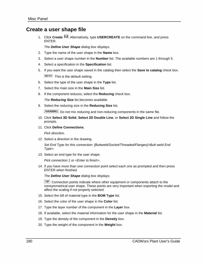
Misc Panel
Create a user shape file 1. Click Create . Alternatively, type USERCREATE on the command line, and press
ENTER.
The Define User Shape dialog box displays.
2. Type the name of the user shape in the Name box.
3. Select a user shape number in the Number list. The available numbers are 1 through 5.
4. Select a specification in the Specification list.
5. If you want the user shape saved in the catalog then select the Save to catalog check box.
This is the default setting.
6. Select the type of the user shape in the Type list.
7. Select the main size in the Main Size list.
8. If the component reduces, select the Reducing check box.
The Reducing Size list becomes available.
9. Select the reducing size in the Reducing Size list.
Do not mix reducing and non-reducing components in the same file.
10. Click Select 3D Solid, Select 2D Double Line, or Select 2D Single Line and follow the prompts.
11. Click Define Connections.
Pick direction.
12. Select a direction in the drawing.
Set End Type for this connection: [Buttweld/Socket/Threaded/Flanges]<Butt weld End Type>.
13. Select an end type for the user shape.
Pick connection 1 or <Enter to finish>.
14. If you have more than one connection point select each one as prompted and then press ENTER when finished.
The Define User Shape dialog box displays.
Connection points indicate where other equipment or components attach to the nonsymmetrical user shape. These points are very important when exporting the model and affect the scaling if not properly selected.
15. Select the bill of material type in the BOM Type list.
16. Select the color of the user shape in the Color list.
17. Type the layer number of the component in the Layer box.
18. If available, select the material information for the user shape in the Material list.
19. Type the density of the component in the Density box.
20. Type the weight of the component in the Weight box.
180 CADWorx Plant User's Guide

Misc Panel 21. Type the length of the component in the Length box.
22. Type the sort sequence for the user shape in the Sort Sequence box.
23. Select Optional Component to make this component an optional component.
24. Type the long description in the Long box. The long description is used within the data file.
25. Type the short description in the Short box.
26. Type the tag information in the Tag box.
27. Type notes in the Notes box, if needed.
The software may automatically define the next five options. If so, you can change or use the information as needed.
28. Type the ISOGEN identifier in the Identifier box.
29. Select an SKEY in the SKEY list.
30. Type the component class in the Component Class box.
31. Type the temperature rating in the Temperature Rating box.
32. Type the pressure rating in the Pressure Rating box.
33. Click OK.
The software creates the user shape.
The user shape is now available on the Misc (on page 541) toolbar. For more information on placing the user shape, see Place a symmetrical user shape in the drawing (on page 197) or Place a nonsymmetrical user shape in the drawing (on page 197).
Edit an existing user shape 1. Click Create . Alternatively, type USERCREATE on the command line, and press
ENTER.
2. Select the name of the user shape, you want to modify, in the Name box.
The software auto-populates the boxes with the information you used when you initially created the shape.
3. Change any other data as needed.
4. When finished making changes to the file, click OK.
The software updates the user shape.
The user shape is now available on the Misc (on page 541) toolbar. For more information on placing the user shape, see Place a symmetrical user shape in the drawing (on page 197) or Place a nonsymmetrical user shape in the drawing (on page 197).
Edit by redefining connection points Command line: EDITUSERSHAPE
Enables you to redefine connection points on user shapes.
When you import legacy user shape data, the software may not map the connection points. Use EDITUSERSHAPE to define the user shape connection points.
CADWorx Plant User's Guide 181

Misc Panel 1. Type EDITUSERSHAPE on the command line, and then press ENTER.
2. Select the user shape to edit.
3. Select connection points for each point you want to change, and then select an end type.
4. Changing the connections points and end types, and then press ENTER to finish.
The connection points update in the drawing and the catalog, with routing points added to the user shape.
ISOGEN Export Options Select connection points based on the images below, where one is the first pick, two is the second pick, and so on.
PCF Identification Valid SKEY Connection Points
Connection Points Order
NUT BNUT 1
CAP KA** 2
MISC-COMPONENT-
RETURN
BR** 2
182 CADWorx Plant User's Guide
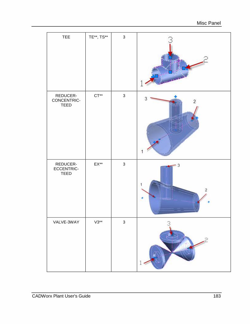
Misc Panel
TEE TE**, TS** 3
REDUCER- CONCENTRIC-
TEED
CT** 3
REDUCER- ECCENTRIC-
TEED
EX** 3
VALVE-3WAY V3** 3
CADWorx Plant User's Guide 183

Misc Panel
VALVE-4WAY V4** 4
MISC-COMPONENT-
ANGLE
BA** 3
CROSS CR** 4
184 CADWorx Plant User's Guide

Misc Panel
MISC-COMPONENT-
OFFSET*^
BO** 4
VALVE-MULTIWAY-
***
MD** 7
VALVE-MULTIWAY-
***
MD** 9
*^For MISC-COMPONENT-OFFSET, point 1 and point 2 are required. Point 3 and Point 4 are optional.
CADWorx Plant User's Guide 185
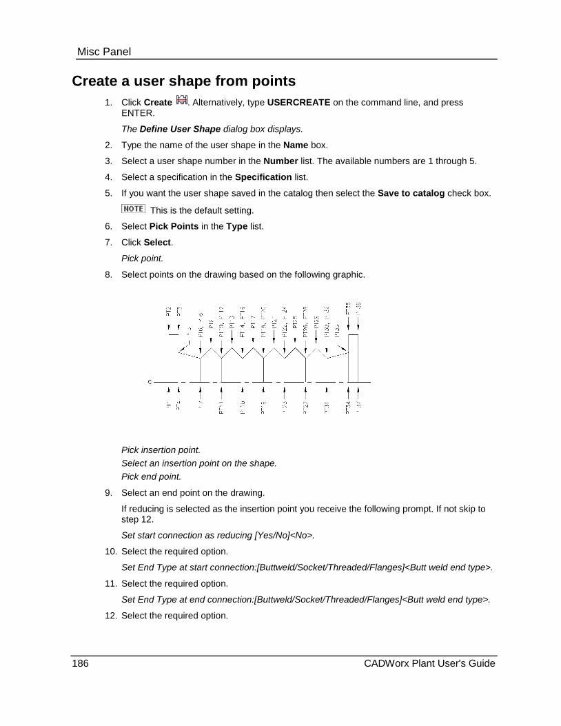
Misc Panel
Create a user shape from points 1. Click Create . Alternatively, type USERCREATE on the command line, and press
ENTER.
The Define User Shape dialog box displays.
2. Type the name of the user shape in the Name box.
3. Select a user shape number in the Number list. The available numbers are 1 through 5.
4. Select a specification in the Specification list.
5. If you want the user shape saved in the catalog then select the Save to catalog check box.
This is the default setting.
6. Select Pick Points in the Type list.
7. Click Select.
Pick point.
8. Select points on the drawing based on the following graphic.
Pick insertion point. Select an insertion point on the shape. Pick end point.
9. Select an end point on the drawing.
If reducing is selected as the insertion point you receive the following prompt. If not skip to step 12.
Set start connection as reducing [Yes/No]<No>.
10. Select the required option.
Set End Type at start connection:[Buttweld/Socket/Threaded/Flanges]<Butt weld end type>.
11. Select the required option.
Set End Type at end connection:[Buttweld/Socket/Threaded/Flanges]<Butt weld end type>.
12. Select the required option.
186 CADWorx Plant User's Guide

Misc Panel
The Define User Shape dialog box displays.
13. Select the main size in the Main Size list.
14. If the component reduces, select the Reducing check box.
The Reducing Size list becomes available.
15. Select the reducing size in the Reducing Size list.
Do not mix reducing and non-reducing components in the same file.
16. Select the bill of material type in the BOM Type list. For more information, see User Shapes (on page 176).
17. Select the color of the user shape in the Color list.
18. Type the layer number of the component in the Layer box.
19. If available, select the material information for the user shape in the Material list.
20. Type the density of the component in the Density box.
21. Type the weight of the component in the Weight box.
22. Type the length of the component in the Length box.
23. Type the sort sequence for the user shape in the Sort Sequence box.
24. Select Optional Component if you want this to be an optional component.
25. Type the long description in the Long box. The long description is used within the data file.
26. Type the short description in the Short box.
27. Type the tag information in the Tag box.
28. Type notes in the Notes box, if needed.
The software may automatically define the next five options. If so, you can change or use the information as needed.
29. Type the ISOGEN identifier in the Identifier box.
30. Select an SKEY in the SKEY list.
31. Type the component class in the Component Class box.
32. Type the temperature rating in the Temperature Rating box.
33. Type the pressure rating in the Pressure Rating box.
34. Click OK.
The software creates the user shape.
The user shape is now available on the Misc (on page 541) toolbar. For more information on placing the user shape, see Place a symmetrical user shape in the drawing (on page 197) or Place a nonsymmetrical user shape in the drawing (on page 197).
CADWorx Plant User's Guide 187
Misc Panel
Create a user shape from a polyline 1. Click Create . Alternatively, type USERCREATE on the command line, and press
ENTER.
The Define User Shape dialog box displays.
2. Type the name of the user shape in the Name box.
3. Select a user shape number in the Number list. The available numbers are 1 through 5.
4. Select a specification in the Specification list.
5. If you want the user shape saved in the catalog then select the Save to catalog check box.
This is the default setting.
6. Select Polyline in the Type list.
7. Click Select.
Select polyline.
8. Select the polyline that defines the shape.
The Selection dialog box displays.
9. Select the required option.
Pick insertion point.
10. Select the insertion point on the model.
Pick end point.
11. Select the end point on the model.
The prompt below only displays if you have a reducing component in the user shape.
Set start connection as reducing [Yes/No]<No>.
12. Select the required option.
Set End Type at start connection:[Buttweld/Socket/Threaded/Flanges]<Butt weld End Type>.
13. Select the required option.
Set EndType at end connection:[Buttweld/Socket/Threaded/Flanges]<Butt weld End Type>. The Define User Shape dialog box displays.
14. Select the main size in the Main Size list.
15. If the component reduces, select the Reducing check box.
The Reducing Size list becomes available.
16. Select the reducing size in the Reducing Size list.
Do not mix reducing and non-reducing components in the same file.
17. Select the bill of material type in the BOM Type list.
18. Select the color of the user shape in the Color list.
19. Type the layer number of the component in the Layer box.
188 CADWorx Plant User's Guide

Misc Panel 20. If available, select the material information for the user shape in the Material list.
21. Type the density of the component in the Density box.
22. Type the weight of the component in the Weight box.
23. Type the length of the component in the Length box.
24. Type the sort sequence for the user shape in the Sort Sequence box.
25. Select Optional Component if you want this to be an optional component.
26. Type the long description in the Long box. The long description is used within the data file.
27. Type the short description in the Short box.
28. Type the tag information in the Tag box.
29. Type notes in the Notes box, if needed.
The software may automatically define the next five options. If so, you can change or use the information as needed.
30. Type the ISOGEN identifier in the Identifier box.
31. Select an SKEY in the SKEY list.
32. Type the component class in the Component Class box.
33. Type the temperature rating in the Temperature Rating box.
34. Type the pressure rating in the Pressure Rating box.
35. Click OK.
The software creates the user shape.
The user shape is now available on the Misc (on page 541) toolbar. For more information on placing the user shape, see Place a symmetrical user shape in the drawing (on page 197) or Place a nonsymmetrical user shape in the drawing (on page 197).
Create a user shape from a block 1. Click Create . Alternatively, type USERCREATE on the command line, and press
ENTER.
The Define User Shape dialog box displays.
2. Type the name of the user shape in the Name box.
3. Select a user shape number in the Number list. The available numbers are 1 through 5.
4. Select a specification in the Specification list.
5. If you want the user shape saved in the catalog then select the Save to catalog check box.
This is the default setting.
6. Select Block from the Type list.
7. Select the main size in the Main Size list.
8. If the component reduces, select the Reducing check box.
The Reducing Size list becomes available.
CADWorx Plant User's Guide 189

Misc Panel 9. Select the reducing size in the Reducing Size list.
Do not mix reducing and non-reducing components in the same file.
10. Click Select 3D Solid, Select 2D Double Line, or Select 2D Single Line and follow the prompts.
11. Click Define Connections.
Pick direction.
12. Select a direction in the drawing.
Set End Type for this connection: [Buttweld/Socket/Threaded/Flanges]<Butt weld End Type>.
13. Select an end type for the connection.
Pick connection 1 or <Enter to finish>.
14. Select a connection point on the drawing.
Pick direction.
15. Select a direction in the drawing.
Set End Type for this connection: [Buttweld/Socket/Threaded/Flanges]<Butt weld End Type>.
16. Select an end type for the connection.
Pick connection 2 or <Enter to finish>.
17. Press ENTER to finish.
The Define User Shape dialog box displays.
Connection points indicate where other equipment or components attach to the nonsymmetrical user shape. These points are very important when exporting the model and affect the scaling if not properly selected.
18. Select the bill of material type in the BOM Type list.
19. Select the color of the user shape in the Color list.
20. Type the layer number of the component in the Layer box.
21. If available, select the material information for the user shape in the Material list.
22. Type the density of the component in the Density box.
23. Type the weight of the component in the Weight box.
24. Type the length of the component in the Length box.
25. Type the sort sequence for the user shape in the Sort Sequence box.
26. Select Optional Component if you want this to be an optional component.
27. Type the long description in the Long box. The long description is used within the data file.
28. Type the short description in the Short box.
29. Type the tag information in the Tag box.
190 CADWorx Plant User's Guide
Misc Panel 30. Type notes in the Notes box, if needed.
The software may automatically define the next five options. If so, you can change or use the information as needed.
31. Type the ISOGEN identifier in the Identifier box.
32. Select an SKEY in the SKEY list.
33. Type the component class in the Component Class box.
34. Type the temperature rating in the Temperature Rating box.
35. Type the pressure rating in the Pressure Rating box.
36. Click OK.
The software creates the user shape.
The user shape is now available on the Misc (on page 541) toolbar. For more information on placing the user shape, see Place a symmetrical user shape in the drawing (on page 197) or Place a nonsymmetrical user shape in the drawing (on page 197).
Create a 3D user shape 1. Click Create . Alternatively, type USERCREATE on the command line, and press
ENTER.
The Define User Shape dialog box displays.
2. Type the name of the user shape in the Name box.
3. Select a user shape number in the Number list. The available numbers are 1 through 5.
4. Select a specification in the Specification list.
5. If you want the user shape saved in the catalog then select the Save to catalog check box.
This is the default setting.
6. Select the type of the user shape in the Type list.
7. Select the main size in the Main Size list.
8. If the component reduces, click the Reducing check box.
The Reducing Size list becomes available.
9. Select the reducing size in the Reducing Size list.
Do not mix reducing and non-reducing components in the same file.
10. Click Select 3D Solid.
Select 3D solid representation.
11. Click a point in the upper left of the drawing, drag the mouse, and then click in the lower right of the drawing to select the entire user shape to create. Press ENTER to finish selection.
Pick insert point.
12. Select an insertion point on the component.
CADWorx Plant User's Guide 191
Misc Panel 13. Click Define Connections.
Pick direction.
14. Select a direction in the drawing.
Set End Type for this connection: [Buttweld/Socket/Threaded/Flanges]<Butt weld End Type>.
15. Select an end type for the user shape.
Pick connection 1 or <Enter to finish>.
16. If you have more than one connection point select each one as prompted, and then press ENTER when finished.
The Define User Shape dialog box displays.
Connection points indicate where other equipment or components attach to the nonsymmetrical user shape. These points are very important when exporting the model and affect the scaling if not properly selected.
17. Select the bill of material type in the BOM Type list.
18. Select the color of the user shape in the Color list.
19. Type the layer number of the component in the Layer box.
20. If available, select the material information for the user shape in the Material list.
21. Type the density of the component in the Density box.
22. Type the weight of the component in the Weight box.
23. Type the length of the component in the Length box.
24. Type the sort sequence for the user shape in the Sort Sequence box. 25. Select Optional Component if you want this to be an optional component. 26. Type the long description in the Long box. The long description is used within the data file. 27. Type the short description in the Short box. 28. Type the tag information in the Tag box. 29. Type notes in the Notes box, if needed.
The software may automatically define the next five options. If so, you can change or use the information as needed.
30. Type the ISOGEN identifier in the Identifier box. 31. Select an SKEY in the SKEY list. 32. Type the component class in the Component Class box. 33. Type the temperature rating in the Temperature Rating box. 34. Type the pressure rating in the Pressure Rating box. 35. Click OK.
The software creates the user shape.
The user shape is now available on the Misc (on page 541) toolbar. For more information on placing the user shape, see Place a symmetrical user shape in the drawing (on page 197) or Place a nonsymmetrical user shape in the drawing (on page 197).
192 CADWorx Plant User's Guide
Misc Panel
Create a 2D user shape 1. Click Create . Alternatively, type USERCREATE on the command line, and press
ENTER.
The Define User Shape dialog box displays.
2. Type the name of the user shape in the Name box.
3. Select a user shape number in the Number list. The available numbers are 1 through 5.
4. Select a specification in the Specification list.
5. If you want the user shape saved in the catalog then select the Save to catalog check box.
This is the default setting.
6. Select the type of the user shape in the Type list.
7. Select the main size in the Main Size list.
8. If the component reduces, select the Reducing check box.
The Reducing Size list becomes available.
9. Select the reducing size in the Reducing Size list.
Do not mix reducing and non-reducing components in the same file.
10. Click Select 2D Double Line.
Select 2D double line representation.
11. Click a point in the upper left of the drawing, drag the mouse, and then click in the lower right of the drawing to select the entire user shape to create. Press ENTER to finish selection.
Pick insert point.
12. Select an insertion point on the component.
13. Click Define Connections.
Pick direction.
14. Select a direction in the drawing.
Set End Type for this connection: [Buttweld/Socket/Threaded/Flanges]<Butt weld End Type>.
15. Select an end type for the user shape.
Pick connection 1 or <Enter to finish>.
16. If you have more than one connection point, select each one as prompted, and then press ENTER when finished.
The Define User Shape dialog box displays.
Connection points indicate where other equipment or components attach to the nonsymmetrical user shape. These points are very important when exporting the model and affect the scaling if not properly selected.
17. Select the bill of material type in the BOM Type list.
CADWorx Plant User's Guide 193
Misc Panel 18. Select the color of the user shape in the Color list.
19. Type the layer number of the component in the Layer box.
20. If available, select the material information for the user shape in the Material list.
21. Type the density of the component in the Density box.
22. Type the weight of the component in the Weight box.
23. Type the length of the component in the Length box.
24. Type the sort sequence for the user shape in the Sort Sequence box.
25. Select Optional Component if you want this to be an optional component.
26. Type the long description in the Long box. The long description is used within the data file.
27. Type the short description in the Short box.
28. Type the tag information in the Tag box.
29. Type notes in the Notes box, if needed.
The software may automatically define the next five options. If so, you can change or use the information as needed.
30. Type the ISOGEN identifier in the Identifier box.
31. Select an SKEY in the SKEY list.
32. Type the component class in the Component Class box.
33. Type the temperature rating in the Temperature Rating box.
34. Type the pressure rating in the Pressure Rating box.
35. Click OK.
The software creates the user shape.
The user shape is now available on the Misc (on page 541) toolbar. For more information on placing the user shape, see Place a symmetrical user shape in the drawing (on page 197) or Place a nonsymmetrical user shape in the drawing (on page 197).
Create a 2D single line user shape 1. Click Create . Alternatively, type USERCREATE on the command line, and press
ENTER.
The Define User Shape dialog box displays.
2. Type the name of the user shape in the Name box.
3. Select a user shape number in the Number list. The available numbers are 1 through 5.
4. Select a specification in the Specification list.
5. If you want the user shape saved in the catalog then select the Save to catalog check box.
This is the default setting.
6. Select the type of the user shape in the Type list.
7. Select the main size in the Main Size list.
194 CADWorx Plant User's Guide

Misc Panel 8. If the component reduces, select the Reducing check box.
The Reducing Size list becomes available.
9. Select the reducing size in the Reducing Size list.
Do not mix reducing and non-reducing components in the same file.
10. Click Select 2D Single Line.
Select 2D single line representation.
11. Click a point in the upper left of the drawing, drag the mouse, and then click in the lower right of the drawing to select the entire user shape to create. Press ENTER to finish selection.
Pick insert point.
12. Select an insertion point on the component.
13. Click Define Connections.
Pick direction.
14. Select a direction in the drawing.
Set End Type for this connection: [Buttweld/Socket/Threaded/Flanges]<Butt weld End Type>.
15. Select an end type for the user shape.
Pick connection 1 or <Enter to finish>.
16. If you have more than one connection point, select each one as prompted, and then press ENTER when finished.
The Define User Shape dialog box displays.
Connection points indicate where other equipment or components attach to the nonsymmetrical user shape. These points are very important when exporting the model and affect the scaling if not properly selected.
17. Select the bill of material type in the BOM Type list.
18. Select the color of the user shape in the Color list.
19. Type the layer number of the component in the Layer box.
20. If available, select the material information for the user shape in the Material list.
21. Type the density of the component in the Density box.
22. Type the weight of the component in the Weight box.
23. Type the length of the component in the Length box.
24. Type the sort sequence for the user shape in the Sort Sequence box.
25. Select Optional Component if you want this to be an optional component.
26. Type the long description in the Long box. The long description is used within the data file.
27. Type the short description in the Short box.
28. Type the tag information in the Tag box.
CADWorx Plant User's Guide 195

Misc Panel 29. Type notes in the Notes box, if needed.
The software may automatically define the next five options. If so, you can change or use the information as needed.
30. Type the ISOGEN identifier in the Identifier box. 31. Select an SKEY in the SKEY list. 32. Type the component class in the Component Class box. 33. Type the temperature rating in the Temperature Rating box. 34. Type the pressure rating in the Pressure Rating box. 35. Click OK.
The software creates the user shape. The user shape is now available on the Misc (on page 541) toolbar. For more
information on placing the user shape, see Place a symmetrical user shape in the drawing (on page 197) or Place a nonsymmetrical user shape in the drawing (on page 197).
Add a user shape to a specification Adds a user shape to the specification.
If Spec Editor is already displayed skip to step 2. 1. Click Start Spec Editor on the spec view palette. Alternatively, click Spec Editor on the
desktop. The Specification Editor software opens.
2. Click File > Open. The Open File dialog box displays.
3. Select a catalog, and then click Open. The Catalog Data window displays.
4. Click the (+) sign on the Data Tables folder. The Data Tables list displays.
5. Right-click User Shapes, and select Add Data Table . The New Usershape Table displays.
6. Type the name of the table in the Name box. 7. Select a user type in the Type list. 8. Select a size table in the Size Table list.
You can select and clear multiple sizes by clicking the Size Table ellipsis. 9. Select the Reducing Component check box if you want this to be a reducing component. 10. Type the user shape folder name in the Usershape Folder box. 11. Type the part number in the Part Number box. 12. Type the description of the user shape in the Description box. 13. Click OK.
The user shape file appears under the User Shape category in the Data Tables folder, and also to the right of Catalog Data, in the Main Table List View.
14. Click File > Save to save the changes to the catalog.
You can now enter information for the specifics of the user shape that you have added to this specification catalog. For more information, see Add a new data table in CADWorx Spec Editor User's Guide.
196 CADWorx Plant User's Guide

Misc Panel
Place a symmetrical user shape in the drawing 1. Click and hold Create on the Misc toolbar.
A list of numbered buttons displays.
2. Click the numbered button associated with the shape to place.
3. Select a point in the drawing.
4. Select a direction in the drawing, or type Up or Down.
The software places the shape in the drawing.
Place a nonsymmetrical user shape in the drawing 1. Click and hold Create on the Misc toolbar.
A list of numbered buttons displays.
2. Click the numbered button associated with the shape to place.
3. Select the start point for the shape in the drawing.
4. Select the rotation option that meets your requirements.
The software places the shape in the drawing.
Top Works Add CADWorx Plant I tab: Misc > Top Works Add
Operators toolbar: Top Works Add
Command line: TOPWORKSADD
Adds top works to a valve already drawn in the model.
CADWorx Plant User's Guide 197

Misc Panel
Top Works Change CADWorx Plant I tab: Misc > Top Works Change
Operators toolbar: Top Works Change
Command line: TOPWORKSCHANGE
Changes the orientation of or deletes top works already associated with a valve.
System Out CADWorx Plant I tab: MISC > System Out
Plant menu: Accessory > CAESAR II > System Out
Command line: C2OUT
Creates a CAESAR II input file. This input file can then be used in CAESAR II without any modification. Components selected in the drawing convert to the appropriate elements for the stress model. For example, a tee connected to pipe in all directions is represented with one node at the intersection instead of four (three at the ends and one at the intersection). This provides the stress analyst a model that is ready for use. All pertinent information is transferred (weights, wall thickness, and so on).
The selection process in the drawing environment is available in two ways. The first requires selecting the components with the standard selection processes in AutoCAD. This can include selection by crossing, window or any other preferred method. The second selection process allows the selection by line number or selecting a component with an existing line number. The database option is not available with this command.
You must set the LanguageFile to the regional language when using a language-specific specification. For example, if you have Chinese characters in your specification, set the LanguageFile to Chinese_Simplified.dic. If you do not, System Out (on page 198) and System In (on page 206) do not function correctly. For more information, see LanguageFile (on page 38).
Generate a CAESAR II input file 1. Click System Out . Alternatively, type C2OUT on the command line, and press ENTER.
The CAESAR II Output File dialog box displays. 2. Specify the location and file name for the file, and click Save.
Enter an option [Database/Line number/Select component] <Select component>. 3. Select Line Number to select components using line numbers.
Enter an option [List/Select component] <Select component>. 4. Choose List to select the line number from a list. For more information, see Select Item
Dialog Box (on page 166). or Choose Select component to select the needed components by crossing, window, or any other preferred method. Provide start locations [Yes/No] <No>
5. Select Yes to provide a start and direction, or select No to process all of the components. 6. Press ENTER to finish the selection.
198 CADWorx Plant User's Guide

Misc Panel Example 1. Select the starting point at node 10.
2. Select anywhere along the centerline toward node 90 for a direction.
3. Select the intersection at 30, and then select a direction toward 50.
4. Select a point at 40 and then select a direction toward 50.
5. Select the intersection at 50 and then select a direction toward 70.
6. You could let CAESAR II automatically node the rest of the model, or you could finish by manually selecting the next point at 30 and then selecting a direction toward 90.
7. Select a point at 50 and then select a direction toward 110.
8. Select a point at 40 and then select a direction toward 150.
Make sure Ortho is off, and use OSnap NEArest to pick along centerlines for directions.
CADWorx Plant User's Guide 199
Misc Panel
Break Pipe CADWorx Plant I tab: Misc > Break Pipe
Command line: BREAKPIPE
Changes non-segmented piping to segmented piping.
Length - Specifies breaking the segments by length of the segments.
Number - Specifies breaking the segments by the number of segments.
What do you want to do? Break by Length (on page 200)
Break by Number (on page 200)
Break by Length 1. Click Break Pipe on the Misc panel in the CADWorx Plant I tab.
2. Type L on the command line, and then press ENTER.
3. Type the length on the command line, and then press ENTER.
4. Select the pipe to break.
The piping breaks into segments based on the value entered for Length.
Break by Number 1. Click Break Pipe on the Misc panel in the CADWorx Plant I tab.
2. Type N on the command line, and then press ENTER.
3. Type the number of segments on the command line, and then press ENTER.
4. Select the pipe to break.
The piping breaks into segments based on the value entered for Number.
Nozzle Generic Attach CADWorx Plant I tab: Misc > Nozzle Generic Attach
Command line: ENGENERIC
Draws a generic nozzle object in the drawing. You can use the information later in bill of material extraction, labeling, and so forth. A project, a specification, and a Main size must be set before you can draw a generic nozzle.
Description - Specifies the description of the nozzle generic attachment.
Equipment Name - Specifies the name of the equipment nozzle generic attachment that you are creating or editing.
Size - Specifies the nominal size of the generic nozzle. You can edit the size with the list.
200 CADWorx Plant User's Guide

Misc Panel Flange Rating - Specifies the flange rating for the nozzle generic attachment that you are creating or editing.
Flange Thickness - Specifies the flange thickness for the nozzle generic attachment that you are creating or editing.
Flange Type - Specifies the flange type for the nozzle generic attachment that you are creating or editing.
Layer - Specifies the layer for the generic nozzle.
Color - Specifies the color for the generic nozzle. You can use the Select Color option from the list to open the AutoCAD Color Index, and select any color.
Points List - Enables you to select the face end and buttweld end points for the nozzle generic attachment.
Face end - Specifies the face end point with a red arrow on the nozzle generic attachment.
Buttweld end - Specifies the buttweld end point with a green arrow on the nozzle generic attachment.
Specify On-Screen - Enables you to specify the face end and buttweld end points on the nozzle generic attachment on screen by the X, Y, and Z. These coordinates can also be entered manually. Specifying the end and middle points sets those points for the routing point for the next nozzle.
Remove – Removes the existing xdata from the generic nozzle. Alternatively, you can use ENGENERICREMOVE to remove data from any generic nozzle.
What do you want to do? Place a nozzle generic attachment (on page 201)
Route from a generic nozzle (on page 202)
Change position and direction of generic nozzle (on page 202)
Place a nozzle generic attachment 1. Click Nozzle Generic Attach . Alternatively, type ENGENERIC on the command line,
and press ENTER.
2. Select the nozzle flange face point in the drawing.
3. Select the nozzle buttweld end point in the drawing.
The Nozzle Generic Attach (Edit) dialog box displays.
4. Type a description in the Description box.
5. Type an equipment name in the Equipment Name box.
6. Select a size from the Size list if needed. Main size must be set before you can draw a generic nozzle.
7. To change the flange rating, select a rating from the Flange Rating list. A project and specification must be set before you can draw a generic nozzle.
8. Type the thickness of the flange in the Flange Thickness box. This must be higher than zero.
CADWorx Plant User's Guide 201

Misc Panel 9. Select a Flange Type from the list.
10. Select a layer from the Layer list, or leave the default.
11. Select a color from the Color list, or leave the default.
12. Click OK.
A red arrow indicates the end point. The start and end points can be re-specified after the
nozzle generic attachment is drawn.
To edit the generic nozzle, double-click it in the drawing.
Route from a generic nozzle 1. Select the generic nozzle in the drawing.
A plus grip displays.
2. Click the plus grip point .
3. Route pipe as needed in any direction, or select an option.
Change position and direction of generic nozzle 1. Select the generic nozzle in the drawing.
A grip point displays.
2. Select one of the two grip points to define the nozzle direction or position.
Generic Attach CADWorx Plant I tab: Misc > Generic Attach
Misc toolbar: Generic Attach
Command line: GENERIC
Attaches information to any generic AutoCAD object in the drawing. You can use the information later in bill of material extraction, labeling, and so forth. After manually constructing a component, use this routine to attach xdata information.
Generic Attach Dialog Box Specifies the details for the generic attach.
Alpha size - Specifies a size-only description of the component.
Short annotation - Specifies a short description of the component.
Long annotation - Specifies a long description of the component.
Line number - Specifies the line number of the component.
Tag - Specifies a tag for the component.
Code - Specifies a code for the component.
Weight - Specifies the weight per unit of a pipe component.
202 CADWorx Plant User's Guide
Misc Panel Sort sequence - Specifies the sort sequence of the component in the bill of material.
Length - Specifies a length for the component.
Component type - Displays the type of the component.
Specification - Displays the specification used by the component.
Coordinates
World - Calculates pipe length based on the pipe component centerline. This option only affects pipe, nipple, flanged pipe, and tubing components. It does not affect fixed-size components such as elbows or flanges. If a pipe component is stretched, trimmed, or broken, the positions of the components are automatically updated along with the pipe length.
Iso - Specifies the value of Length as the pipe length. The length does not change the drawing graphics, but appears in the bill of material. For more information, see ISO Flag (on page 210).
Miscellaneous
Existing - Specifies that the component is not included in the bill of material. The component symbol is also moved to the Exist layer. In ISOGEN isometric drawings, the component is shown as dotted and dimensioned.
Insulation or CAESAR II - Specifies that this component either has CAESAR II pipe stress analysis information or insulation attached.
BOM Item Type
Fabrication - Specifies a fabrication type of bill of material item.
Erection - Specifies an erection type of bill of material item.
Offshore - Specifies an offshore type of bill of material item.
Misc - Specifies a miscellaneous type of bill of material item.
The selected item type appears on the bill of materials when the FLAG column is added
using Pipe BOM / DB > Setup . For ISOGEN, you must also sort by the FLAG column to group by type. For more information, see Bill of Material Setup (on page 154) and BOM Sort Order / Accumulation Dialog Box (on page 157).
If Misc is selected when using ISOGEN, then ISOGEN treats the weld gap as a field-fit weld. Use ISOGEN Option Switch 22 to increase the cut piece add-on allowances for field-fit welds.
ISOGEN - Specifies data for the component in an ISOGEN drawing. Opens the ISOGEN Data dialog box.
ISOGEN Data Dialog Box (on page 73)
Custom Data - Specifies custom data created in the Specification Editor and enables you to edit the value. This data can be isolated in the Line View palette.
For more information on creating custom data, see New Field Dialog Box in the CADWorx Spec Editor Users Guide.
Click the link for more information on the Component Custom Data Dialog Box (on page 78).
CADWorx Plant User's Guide 203

Misc Panel Remove - Removes CADWorx database attributes from a component, converting it to generic AutoCAD geometry.
Many commands in CADWorx use xdata in the components and do not function if the data is removed.
BOM/CG Point - Displays the Get BOM/CG Location dialog box, which enables you to specify the bill of material location and the center of gravity location.
Attach - Saves modifications and closes the dialog box.
Cancel - Cancels the operation without saving modifications, and closes the dialog box.
Get BOM/CG Location Dialog Box BOM Mark Point - Shows the drawing coordinate location at which the information was attached.
Specify On-screen - Click the location in the model view to specify the bill of material mark point.
View - Displays the BOM Mark Point.
X - Specifies the X-location for the bill of material mark point. This value defaults to zero.
Y - Specifies the Y-location for the bill of material mark point. This value defaults to zero.
Z - Specifies the Z-location for the bill of material mark point. This value defaults to zero.
CG Location - Shows the center of gravity location at which the information was attached.
Specify On-screen - Click the location in the model view to specify the generic attach center of gravity point.
View - Displays the CG Location.
X - Specifies the X-location for the generic attach center of gravity location. This value defaults to zero.
Y - Specifies the Y-location for the generic attach center of gravity location. This value defaults to zero.
Z - Specifies the Z-location for the generic attach center of gravity location. This value defaults to zero.
You cannot attach information to a CADWorx object or component.
To pinpoint the center of gravity locations use the Osnap commands. For example, to place information on a beam and have it correctly reflect the center of gravity, draw a centerline and pick MIDpoint, NEArest to the end of the centerline, or the exact location.
Place a generic attachment in the drawing 1. Click Generic Attach . Alternatively, type GENERIC on the command line, and press
ENTER.
The Generic Attach dialog box displays.
2. Alpha Size auto-populates with the main size already selected when you set up the drawing. Type the alpha size in the Alpha size box, if you need to change it.
3. Type an abbreviated description, such as PUMP 2X1X8, in the Short annotation box.
204 CADWorx Plant User's Guide
Misc Panel 4. Type a complete description, such as PUMP, INGERSOLL-RAND, MODEL HOC, 2X1X8, in
the Long annotation box.
5. Type a line number in the Line number box, if you want to assign a line number to the component.
6. Type the tag in the Tag box.
7. Type the code in the Code box, if you want to assign a code to the component.
8. Type the weight of the component in the Weight box.
9. Type the sort sequence number for the bill of material schedule location in the Sort sequence box.
10. Type the length of the component in the Length box.
11. Change the Coordinates if available and needed.
12. Select Existing in the Miscellaneous column, if needed.
13. Change the BOM Item Type, if needed.
14. Click Attach.
15. Select the object to attach the information.
The software attaches the information to the object, and a red arrow displays indicating the BOM Mark Point.
16. Press ENTER.
Specify the Bill of Material Mark Point and the Center of Gravity Location
1. Double-click the entity.
The Component Edit dialog box displays.
2. Click BOM/CG Point.
3. Click Specify On-screen under BOM Mark Point.
4. Select a point on the object to specify the mark point.
A red arrow displays indicating the point.
5. Click Specify On-screen under CG Location.
6. Select a point on the object to specify the mark point.
A green arrow displays indicating the location.
7. Click OK.
CADWorx Plant User's Guide 205
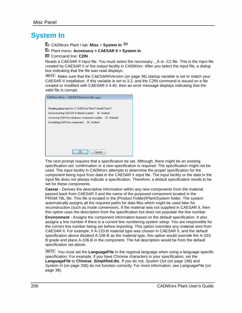
Misc Panel
System In CADWorx Plant I tab: Misc > System In Plant menu: Accessory > CAESAR II > System In Command line: C2IN
Reads a CAESAR II input file. You must select the necessary ._A or .C2 file. This is the input file created by CAESAR II or the output facility in CADWorx. After you select the input file, a dialog box indicating that the file was read displays.
Make sure that the CAESARIIVersion (on page 36) startup variable is set to match your CAESAR II installation. If this variable is set to 3.2, and the C2IN command is issued on a file created or modified with CAESAR II 4.40, then an error message displays indicating that the valid file is corrupt.
The next prompt requires that a specification be set. Although, there might be an existing specification set, confirmation or a new specification is required. The specification might not be used. The input facility in CADWorx attempts to determine the proper specification for the component being input from data in the CAESAR II input file. The input facility or the data in the input file does not always indicate a specification. Therefore, a default specification needs to be set for these components. Caesar - Derives the descriptive information within any new components from the material passed back from CAESAR II and the name of the purposed component located in the PRGM.TBL file. This file is located in the [Product Folder]\Plant\System folder. The system automatically assigns all the required paths for data files which might be used later for reconstruction (such as mode conversion). If the material was not supplied in CAESAR II, then this option uses the description from the specification but does not populate the line number. Environment - Assigns the component information based on the default specification. It also assigns a line number if there is a current line numbering system setup. You are responsible for the correct line number being set before importing. This option overrides any material sent from CAESAR II. For example, if A-133-B material type was chosen in CAESAR II, and the default specification above dictated A-106-B as the material type, this option would override the A-333-B grade and place A-106-B in the component. The full description would be from the default specification set above.
You must set the LanguageFile to the regional language when using a language-specific specification. For example, if you have Chinese characters in your specification, set the LanguageFile to Chinese_Simplified.dic. If you do not, System Out (on page 198) and System In (on page 206) do not function correctly. For more information, see LanguageFile (on page 38).
206 CADWorx Plant User's Guide

Misc Panel
Read a CAESAR II input file 1. Click System In . Alternatively, type C2IN on the command line, and press ENTER.
The CAESAR II Input File dialog box displays.
2. Select the file to read, and click Open.
3. Set the default specification, or press ENTER to use the current specification.
The software reads the CAESAR II input file.
4. Select the option that meets your requirements.
The software writes the CAESAR II components in the drawing.
Change Elevation CADWorx Plant I tab: Misc > Change Elevation
Command line: CHANGEELEVATION
Changes the elevation of a selected pipe in the drawing.
Pick - Enables you to select the location for the change in the elevation.
BOP - Changes the elevation location to the bottom of pipe after specifying the elevation change.
TOP - Changes the elevation location to the top of pipe after specifying the elevation change.
Current - Keeps the center of the pipe as the current location after specifying the elevation change.
BOP - Enables you to change the elevation to the bottom of pipe.
TOP - Enables you to change the elevation to the top of pipe.
What do you want to do? Change elevation by entering the elevation value (on page 207)
Change elevation by Pick (on page 208)
Change elevation by BOP (on page 208)
Change elevation by TOP (on page 208)
Change elevation by entering the elevation value 1. Click Change Elevation on the Misc panel in the CADWorx Plant I tab.
2. Select the pipe requiring an elevation change.
3. Type the elevation value on the command line, and then press ENTER.
4. Select the location option (BOP, TOP, Current) to specify where to locate the changed piping.
The piping elevation changes and places at the new location.
CADWorx Plant User's Guide 207

Misc Panel
Change elevation by Pick 1. Click Change Elevation on the Misc panel in the CADWorx Plant I tab.
2. Select the pipe requiring an elevation change.
3. Type P on the command line, and then press ENTER.
4. Select a point in the drawing to move the piping elevation.
The length of pipe must exist in the specification or you get a response that the piping length does not exist.
5. Select the location option (BOP, TOP, Current) to specify where to locate the changed piping.
The piping elevation changes and places at the new location.
Change elevation by BOP 1. Click Change Elevation on the Misc panel in the CADWorx Plant I tab.
2. Select the pipe requiring an elevation change.
3. Type B on the command line, and then press ENTER.
The piping elevation changes to the bottom of the pipe.
Change elevation by TOP 1. Click Change Elevation on the Misc panel in the CADWorx Plant I tab.
2. Select the pipe requiring an elevation change.
3. Type T on the command line, and then press ENTER.
The piping elevation changes to the top of the pipe.
Dim Adjustment Pipe menu: Utility Dim Adjustment
Command line: DIMADJUST
Adjusts a dimension when the pipe segments of a particular run have been adjusted or modified with the ISO flag command. For more information, see ISO Flag (on page 210). This command works with the associate dimensioning setvar DIMASSOC on. The command also adjusts the pipe’s stored xdata length. This is performed by using the dimension to adjust the pipe’s xdata. You can adjust the pipe with Dimension option, or adjust the dimension with Pipe option. Both options of this command read and write fractional characters used with the dimension routines.
Options Dimension - Adjusts the pipe to match an existing dimension. Select the dimension, then select the pipe’s centerline.
Pipe - Adjusts the dimension to match the stored length in the pipe’s xdata.
208 CADWorx Plant User's Guide
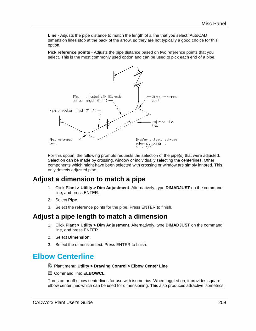
Misc Panel Line - Adjusts the pipe distance to match the length of a line that you select. AutoCAD dimension lines stop at the back of the arrow, so they are not typically a good choice for this option.
Pick reference points - Adjusts the pipe distance based on two reference points that you select. This is the most commonly used option and can be used to pick each end of a pipe.
For this option, the following prompts requests the selection of the pipe(s) that were adjusted. Selection can be made by crossing, window or individually selecting the centerlines. Other components which might have been selected with crossing or window are simply ignored. This only detects adjusted pipe.
Adjust a dimension to match a pipe 1. Click Plant > Utility > Dim Adjustment. Alternatively, type DIMADJUST on the command
line, and press ENTER.
2. Select Pipe.
3. Select the reference points for the pipe. Press ENTER to finish.
Adjust a pipe length to match a dimension 1. Click Plant > Utility > Dim Adjustment. Alternatively, type DIMADJUST on the command
line, and press ENTER.
2. Select Dimension.
3. Select the dimension text. Press ENTER to finish.
Elbow Centerline Plant menu: Utility > Drawing Control > Elbow Center Line
Command line: ELBOWCL
Turns on or off elbow centerlines for use with isometrics. When toggled on, it provides square elbow centerlines which can be used for dimensioning. This also produces attractive isometrics.
CADWorx Plant User's Guide 209
Misc Panel
ISO Flag Plant menu: Utility > ISO Flag
Command line: ISOFLAG
Sets a flag in the component indicating that the present stored length should be used regardless of what type of length modifications are made to the pipe component. This command only affects pipes and nipples. This is useful when adjusting a pipe which is to be used in an isometric. For example, if you use this command before stretching a pipe which was 120'-0" long to 5'-0" long, the Bill of Material generator reflects a 120'-0" long piece of pipe.
The component’s xdata is flagged when using the CEDIT dialog box.
Re-associate the Components CADWorx fieldPipe - CloudWorx Interface Palette: Re-associate the Components Command line: REASSOCIATEMODEL
If you have not purchased fieldPipe, you can only enter the command on the command line. Enables you to re-associate disconnected components. Entire drawing - Re-associates the entire drawing. Select components - Re-associates only the selected components.
Re-associate the Entire drawing 1. Click Re-associate the Components on the on the CADWorx fieldPipe - CloudWorx
Interface palette. Alternatively, type REASSOCIATEMODEL on the command line, and then press ENTER.
2. Select Entire drawing.
The entire drawing is re-associated. Re-associate the Select components 1. Click Re-associate the Components on the on the CADWorx fieldPipe - CloudWorx
Interface palette. Alternatively, type REASSOCIATEMODEL on the command line, and then press ENTER.
2. Select Select components. 3. Select the components you want to re-associate.
The components in the drawing are re-associated.
System Visibility Command line: SYSVIS
Turns on or off visibility of components usually located on the system layer. The command affects the components listed below.
Weld gaps Pads / Saddles Bolts Gaskets TAPs
210 CADWorx Plant User's Guide

S E C T I O N 9
CADWorx Plant I tab: 2D
Command Name Command Line
2D Representation - Creates a 2D representation. For more information, see 2D Representation (on page 211).
2DREP
2D Representation Hidden - Creates a 2D representation with hidden lines. For more information, see 2D Representation Hidden (on page 212).
2DREPH
Box - Creates views based on a picked box. For more information, see Box (on page 212).
VIEWBOX
Edit - Edits a views box. For more information, see Edit (on page 213).
VIEWEDIT
Zoom Lock - Allows zooming in paper space only. For more information, see Zoom Lock (on page 214).
ZOOMLOCK
Zoom Factors - Zooms an Mview to a specified scale. For more information, see Zoom Factors (on page 214).
ZOOMF
2D Representation CADWorx Plant I tab: 2D > 2D Representation
Plant Menu: Accessory > 2D Representation
Command line: 2DREP EQUIP2DREP
Creates a two-dimension representation from a three-dimensional model. This command removes hidden lines and retains layer and color information. It can work in model or paper space. In model space, the 2D representation is created as a block.
An alternate command, 2DREPH (EQUIP2DREPH in CADWorx Equipment), is also available. This command exports the hidden lines from solids to the 2D representation. All other features of this command are similar to the 2DREP command.
Solids - Generates 2D representations of native AutoCAD 3D solids.
Centerlines - Copies selected CADWorx Piping and Steel center lines to the 2D representation.
Lines - Copies selected AutoCAD 3dPolyline, Arc, Circle, Ellipse, Leader, Line, Polyline, Spline and Helix to the 2D representation. This includes CADWorx Piping and Steel center lines.
This command only processes native AutoCAD solid and line entities that are typically created by CADWorx. This command does not process any custom solid or line entities that are created by other add-on AutoCAD applications.
What do you want to do? Create a 2D representation (on page 212) Create a 2D representation with hidden lines (on page 212)
2D Panel
CADWorx Plant User's Guide 211

2D Panel
Create a 2D representation 1. Type 2DREPEQUIP2DREP.
2. Select the objects to include in the 2D representation.
3. Select the filter option that meets your needs.
If you are in paper space, the software asks if you want the viewports to be turned off.
4. Type Yes to turn off the viewports, or type No to leave the viewports on.
This option is useful when there are changes made to the model and the 2D representation needs to be updated. You can turn on the viewport again using the AutoCAD Properties dialog box, and then run the command again.
2D Representation Hidden CADWorx Plant I tab: 2D > 2D Representation Hidden
Plant Menu: Accessory > 2D Representation
Command line: 2DREPH
Creates a 2D representation with hidden lines. This command exports the hidden lines from solids to the 2D representation. All other features of this command are similar to the 2DREP command. For more information, see 2D Representation (on page 211).
Create a 2D representation with hidden lines 1. Type 2DREPHEQUIP2DREPH.
2. Select the objects to include in the 2D representation.
3. Select the filter option that meets your needs. For more information, see 2D Representation (on page 211).
If you are in paper space, the software asks if you want the viewports to be turned off.
4. Type Yes to turn off the viewports, or type No to leave the viewports on.
This option is useful when there are changes made to the model and the 2D representation needs to be updated. You can turn on the viewport again using the AutoCAD Properties dialog box, and then run the command again.
Box CADWorx Plant I tab: 2D > Box
Command line: VIEWBOX
Displays the View Creation dialog box. This dialog box creates clipped views by defining a 3D box. This command is useful in creating layout drawings in paper space.
View Creation Dialog Box
View set name - Specifies the overall set name for the views. Each view created is named based on this name.
212 CADWorx Plant User's Guide

2D Panel First corner point Specify On-screen - Select a point in the model as the first corner point of the view box. Selecting a point in the model automatically fills in values for the X, Y, and Z boxes.
X - Specifies the X-axis value for the view box.
Y - Specifies the Y-axis value for the view box.
Z - Specifies the Z-axis value for the view box. The Z-axis value must be different for the first and second corner points.
Second corner point Specify On-screen - Select a point in the model as the second corner point of the view box. Selecting a point in the model automatically fills in values for the X, Y, and Z boxes.
X - Specifies the X-axis value for the view box.
Y - Specifies the Y-axis value for the view box.
Z - Specifies the Z-axis value for the view box. The Z-axis value must be different for the first and second corner points.
Views View Type - Indicates the orientation of the view.
Name - Specifies the view name. The default name is a combination of the View set name value and the View Type. After you create the view set, the views display in the AutoCAD View dialog box.
Available - Indicates whether the view is included in the set. Select the checkbox to include the view. Clear the checkbox to exclude the view.
Select All - Selects all of the check boxes in the Available column.
Delete All - Deletes all of the AutoCAD views that were previously created with this view set, and close the dialog box.
Set Current - Sets the AutoCAD window to the selected view.
Isolate Box - Hides all AutoCAD entities outside the view box. Entities that cross the boundaries of the view box are not hidden.
Show All - Shows all of the entities in the drawing.
Edit CADWorx Plant I tab: 2D > Edit
Command line: VIEWEDIT
Edits the box created with the VIEWBOX command. Double-clicking an existing view box runs this command. For more information, see Box (on page 212).
CADWorx Plant User's Guide 213
2D Panel
Zoom Lock CADWorx Plant I tab: 2D > Zoom Lock
Plant menu: Utility > Zoom Lock
Settings toolbar:
Command line: ZOOMLOCK
Locks the AutoCAD ZOOM command to allow zooming in paper space only. This means that while you are in paper space with the MSPACE command activated (the cursors are in the Mview), you can zoom without resizing the model space viewport. Instead, this command intercepts the ZOOM command and changes to paper space before zooming. When you are finished zooming, the command returns the cursor and environment back to the Mview.
This command simplifies working on CADWorx isometrics.
What do you want to do? Turn on the zoom lock (on page 214)
Turn off the zoom lock (on page 214)
Turn on the zoom lock Type ZOOMLOCK.
Paperspace zoom lock toggled on.
Turn off the zoom lock Type ZOOMLOCK.
Paperspace zoom lock toggled off.
Zoom Factors Plant menu: Utility > Zoom Factors
Command line: ZOOMF
Zooms an Mview to a specified scale. This command zooms to a perfect scale for your current Mview. If you use this command from model space (tilemode 1), it displays a warning that tilemode has to be set to 0 (paper space). After selecting the scale from one of the menus, a prompt displays requesting the center of the view.
214 CADWorx Plant User's Guide

S E C T I O N 1 0
CADWorx Plant I tab: Bolt
Command Name Command Line
Auto Gasket - Place gaskets automatically after the last flange face drawn. For more information, see Auto Gasket (on page 215).
AUTOGASKET
Automatic - Sizes and places stud bolts automatically at each gasket. For more information, see Automatic (on page 216).
AUTOBOLT
Auto Weld - Places weld gaps automatically after the last butt weld drawn. For more information, see Auto Weld (on page 217).
AUTOWELD
Weld Total - For more information, see Weld Total (on page 218).
WELDTOTAL
Standard - Places standard stud bolts at the selected location. For more information, see Standard (on page 219).
STDBOLT
Non Standard - Places nonstandard stud bolts at the selected location. For more information, see Non Standard (on page 219).
NONSTDBOLT
Auto Gasket CADWorx Plant I tab: Bolt > Auto Gasket
Plant Menu: Utility > Drawing Control > Auto Gasket
Command line: AUTOGASKET
Places a gasket on flange sets, and valves.
Automatic - Places a gasket into the drawing automatically.
Manual - Places a gasket into the drawing manually.
This option can also be set with a piping rule. For more information, see Piping Rules (on page 49).
Bolt
CADWorx Plant User's Guide 215

Bolt
Place a gasket automatically 1. Click Auto Gasket . Alternatively, type AUTOGASKET on the command line, and then
press ENTER.
2. Press ENTER for Automatic.
3. Select the flange set or flange and valve set.
4. Select the branches to add gaskets, or press ENTER to finish.
5. Select a component to keep the position, or press ENTER to finish.
The gasket is placed.
Place a gasket manually 1. Click Auto Gasket . Alternatively, type AUTOGASKET on the command line, and then
press ENTER.
2. Type M on the command line, and press ENTER.
3. Select the flange set or flange and valve set.
4. Select the branches to add gaskets, or press ENTER to finish.
5. Select a component to keep the position, or press ENTER to finish.
The gasket is placed.
Automatic CADWorx Plant I tab: Bolt > Automatic
Command line: AUTOBOLT
Assigns stud bolt sets with similar sizes and specifications to all gaskets within the current selection set. Gaskets of different sizes and specifications are automatically handled.
Automatic - Places a bolt into the drawing automatically.
Manual - Places a bolt into the drawing manually.
When the Bolt Insertion rule is turned on and you place a flange in the drawing it does not have a bolt until you place a flange or a valve on the other side. Only then is the bolt automatically inserted into the drawing when necessary.
This option can also be set with a piping rule. For more information, see Piping Rules (on page 49) and Apply Bolt Insertion Rule (on page 51).
Place stud bolts automatically 1. Click Automatic . Alternatively, type AUTOBOLT on the command line, and then press
ENTER.
2. Press ENTER for Automatic.
3. Select a flange set or flange and valve set.
4. Select the branches to add gaskets, or press ENTER to finish.
The bolt is placed.
216 CADWorx Plant User's Guide

Bolt
Place stud bolts manually 1. Click Automatic . Alternatively, type AUTOBOLT on the command line, and then press
ENTER.
2. Type M on the command line, and press ENTER.
3. Select a flange set or flange and valve set.
The bolt is placed.
Auto Weld CADWorx Plant I tab: Bolt > Auto Weld
Plant Menu: Utility > Drawing Control > Auto Weld
Command line: AUTOWELD
Places weld gaps on every end of any butt weld and socket weld component or only on every end of any butt weld when the component is selected. Three different scenarios can occur when the weld gaps are placed:
1. When a weld gap is automatically placed on the end of a butt weld or socket weld component, do one of the following to place the next component:
Press ENTER to place the component at the weld gap.
Pick the end point of the weld gap symbol.
2. When a component, such as a tee, is inserted into a pipe, and the weld gaps are placed at each end of the tee, the weld gaps automatically break and cut back the pipe on both sides of the tee. If one exists, the branch connection pipe is also broken.
3. When a component is placed against another component that cannot be cut back, a weld gap must already exist. For example, if you are placing a flange against an elbow, the elbow must have an existing weld gap. If not, the software places the flange against the elbow without any gap. In this scenario, it is your responsibility to place a weld gap before placing the flange.
Automatic - Places a weld gap into the drawing automatically.
Manual - Places a weld gap into the drawing manually.
This option can also be set with a piping rule. For more information, see Piping Rules (on
page 49) and Apply Weld Insertion Rule (on page 50).
Setting BOM Item Type to Misc causes ISOGEN to process weld gaps as field fit welds. For more information about the options on the Component Edit dialog box, see Local Edit (on page 70). Use ISOGEN Option Switch 22 to increase cut piece add-on allowances for field fit welds.
Place weld gaps automatically 1. Click Auto Weld . Alternatively, type AUTOWELD on the command line, and then press
ENTER.
2. Press ENTER for Automatic.
CADWorx Plant User's Guide 217

Bolt 3. Select the piping components where you want welds placed, and press ENTER when
finished.
4. Select branches to add welds, or press ENTER to finish.
5. Select a component to keep its position, or press ENTER to finish.
The software displays the number of welds added.
Place weld gaps manually 1. Click Auto Weld . Alternatively, type AUTOWELD on the command line, and then press
ENTER.
2. Type M on the command line, and press ENTER.
3. Select the piping components where you want welds placed, and press ENTER when finished.
4. Select a component to keep its position, or press ENTER to finish.
The software displays the number of welds added.
Weld Total CADWorx Plant I tab: Bolt > Weld Total
Command line: WELDTOTAL
Counts weld gaps on a drawing for estimating purposes.
An example of the typical output is shown below. You can copy this information and paste it
into a text file or to a Microsoft Excel workbook.
Qty. Spec. Nominal Actual Thk. Linear Lg.
5 A0 2.000 2.375 0.154 37.310
4 A0 3.000 3.500 0.216 43.980
14 A1 10.000 10.750 0.365 472.810
1 A1 14.000 14.000 0.375 43.980
150 A1 2.000 2.375 0.154 1119.190
The ability to export the drawing to a database using the DBFGEN or LIVEDB command can also help manage weld gaps.
Setting BOM Item Type to Misc causes ISOGEN to process weld gaps as field fit welds. For more information about the options on the Component Edit dialog box, see Local Edit (on page 70). Use ISOGEN Option Switch 22 to increase cut piece add-on allowances for field fit welds.
What do you want to do? Count weld gaps automatically (on page 219)
218 CADWorx Plant User's Guide

Bolt
Count weld gaps automatically 1. Click Weld Total . Alternatively, type WELDTOTAL on the command line, and then
press ENTER.
2. Select the objects you want to have automatically counted, and then press ENTER.
The software displays a prompt showing the total number of welds in the drawing.
Standard CADWorx Plant I tab: Bolt > Standard
Gaskets, Etc. toolbar: Standard
Command line: PLACEBOLT Inserts stud bolt sets into the drawing environment for Bill of Materials extraction. You can insert a stud bolt set anywhere in the drawing. However, stud bolt sets must be attached to a flange set or flange valve set to be placed on the model. Size and specification must be set accordingly. If the bolt Weight equals 0.0 in the Stud Bolts data table, the software calculates the weight using the Density value from the Material Table and the AutoCAD solid volume of the whole set of bolts. If the bolt Weight is greater than 0.0 for flange-to-flange components, then the software assigns the weight to the bolt set without performing any other calculations. However, when there is a component between the flanges, such as a bleed ring, the software uses the Density and solid volume calculation.
This option is set when the bolt piping rule is set. For more information, see Piping Rules (on page 49) and Apply Bolt Insertion Rule (on page 51). If you need to change the bolt set by the bolt piping rule, delete the bolt placed and place a bolt using this option.
Place standard stud bolts 1. Click Standard . Alternatively, type PLACEBOLT on the command line, and then press
ENTER.
2. Select a point in the drawing.
The bolts display in the drawing.
Non Standard CADWorx Plant I tab: Bolt > Non Standard
Gaskets, Etc. toolbar: Non Standard
Command line: NONSTDBOLT
Inserts a stud bolt set anywhere. However, nonstandard bolt sets must be attached to a flange set or flange valve set to be placed on the model. You can also insert special bolts. Size and specification must be set accordingly.
This option is set when the bolt piping rule is set. For more information, see Piping Rules (on page 49) and Apply Bolt Insertion Rule (on page 51). If you need to change the bolt set by the bolt piping rule, delete the bolt placed and place a bolt using this option.
CADWorx Plant User's Guide 219

Bolt
Place nonstandard stud bolts 1. Click Non Standard . Alternatively, type NONSTDBOLT on the command line and then
press ENTER.
2. Type the required text. For example, you can type NON STD STUD BOLTS.
3. Type the required description. For example, you can type STUD BOLTS W/ DOUBLE NUTS & WASHERS.
4. Type the stud diameter. You must enter the value as a real number, such as 5/8".
5. Type the length. You must enter a real number, such as 7.25 or 7-1/4".
6. Type the required stud value.
7. Type the required weight.
8. Type a string, a real number, or press ENTER to accept the default.
9. Type the value, or press ENTER to accept the default.
10. Select a point in the drawing.
11. Use the compass to pick a direction in the drawing, and click to finish.
The bolt is placed in the drawing.
220 CADWorx Plant User's Guide

S E C T I O N 1 1
CADWorx Plant I tab: RT
Command Name Command Line
Auto Route - Provides the ability to draw components continuously without selecting them from the toolbar or palette. For more information, see Auto Route (on page 221).
AUTOROUTE, ROUTE
Router - Provides routing lines with various options such as slope and elevation changes. For more information, see Router (on page 225).
ROUTER
Buttweld LR - Attaches elbows and piping to a selected routing line. For more information, see Buttweld LR (on page 227).
ROUTEBWLR
Buttweld SR - Attaches elbows and piping to a selected routing line. For more information, see Buttweld SR (on page 227).
ROUTEBWSE
Threaded - Attaches elbows and piping to a selected routing line. For more information, see Threaded (on page 228).
ROUTETRHD
Socket Weld - Attaches elbows and piping to a selected routing line. For more information, see Socket Weld (on page 228).
ROUTESW
Auto Route CADWorx Plant I tab: RT > Auto Route
Command Line: AUTOROUTE, ROUTE You can also use the PIPW command to start routing pipe.
Starts the ROUTE in the X-Y plane as needed. This command can be used to route pipe from one component to another without accessing the pipe, or elbow commands. The command is best used to start a new route of pipe, but it also works to continue routing a previous section of pipe. However, the most useful way to continue routing pipe is to use the + sign on the ends and middle of the pipe. For more information on continuing routing, see Continue Routing (on page 223). last point - Starts the pipe at the last point of the previously-created component.
component List - Displays a list of available components to place in the drawing. All components available display in the list based on the main size you have set.
RT Panel
CADWorx Plant User's Guide 221

RT Panel Slope - Starts the pipe in a slope direction.
Meter - Places the slope rise or drop in the degrees entered based on meters. Foot - Places the slope rise or drop in the degrees entered based on feet. Rise - Places the slope rise or drop based on the degrees entered.
sKew - Places the pipe at a skewed angle and allows you to continue piping. To finish or end the running of skewed piping, you must press ENTER. sKew works in conjunction with the Apply Skew Pipe Maximum Angle rule. CADWorx does not allow the piping to be placed at a greater angle then set in the piping rule. For more information on the rule, see Apply Skew Pipe Maximum Angle (on page 55).
component List - Displays a list of available components to place in the drawing at the skewed point.
Plane - Starts the component in the XYZ plane plotting based on the UCS. Type P on the command line, and then press ENTER to reorient the compass direction.
Undo - Takes you back to the previous step in your process. Elevation - Starts the pipe perpendicular to the plane for routing. Plane - Starts the component in the XYZ plane plotting based on the UCS. Type P on the command line and press ENTER to reorient the compass direction. Reference - Starts the line at a distance based on the reference point chosen. Fitting mode - Starts the pipe as Buttweld, Socket Weld, Threaded, Flanged, or Special Endtype fitting mode, depending on your selection. elBow type - Enables you to select the elbow types based on the fitting mode you have selected. For instance, with Buttweld the list would be Long Radius Buttweld, Short Radius Buttweld, or Miter Elbow Buttweld. However, for Socket Weld the list would be Elbow Socket Weld and Miter Elbow Socket Weld. You can change the fitting mode of the router in the CADWorx Spec View palette. For more information, see Draw pipe components (on page 89). Undo - Undoes the last piece of routed pipe. Connect - Connects to a component or other piece of pipe.
Components - Displays all possible connecting directions to the component or pipe using an image of piping.
Lines - Displays specific lines in a box form for connecting to the component or pipe. Toggle length - Toggles the dimension of the pipe from the start point. Alignment - Starts the pipe at a chosen alignment.
Center - Center of pipe BOP - Bottom of pipe TOP - Top of pipe Left - Left of pipe Right - Right of pipe
TOP - Places the pipe along the top of the pipe, as defined along the Z-axis. BOP - Places the pipe along the bottom of the pipe, as defined along the Z-axis.
What do you want to do? Start a new route (on page 223) Continue Routing (on page 223) Route skewed pipe (on page 224) Moveline (on page 225)
222 CADWorx Plant User's Guide
RT Panel
Start a new route 1. Click Auto Route . Alternatively, type AUTOROUTE, or ROUTE on the command line,
and press ENTER. 2. Select a start point. 3. Select an end point, or select one of the options in the list.
CADWorx lets you continue routing pipe as needed, using the component List and other options to allow you to route to components as needed.
4. When finished routing pipe, press ENTER. The new pipe is inserted in the drawing.
Continue Routing This procedure does not require a command to start. However, the ROUTE command used to start new piping, can also be used to continue routing pipe.
The options below display when selecting the middle grip point on a pipe to insert a component in an already routed piece of piping. If you select the grip point at the end of a piping run the run just continues as a normal pipe with the options listed in Auto Route (on page 221).
List - Displays a list of available components to place in the drawing.
poinT distance - Enables you to specify a point on the pipe or component to move the selected component.
Component distance - Displays the distance from the selected component to the selected piping or component. The distance measured to a specifically selected component can be changed by using Point.
Point - Enables you to change the distance from the selected component to another component on the same linear pipe.
Pipe end point distance - Displays the distance measurement from the selected component to the end of the pipe. Repeating the command changes the direction of the measurement to the opposite end of the piping, where it connects to the next component. insertion Justification - Changes the justification of a selected component from the end of the piping. Justification for the component is left, right, or center. Use the Pipe end point distance option by typing P on the command line, which enables you to change the justification from either end of the piping. Change connection - Enables you to change the direction of a component. This option is only available on certain components when using the List or component List option.
Turning on Auto Connect (on page 174) allows you to continue routing from your last point
without having to click the grip point or without pressing ENTER. Turn off Auto Connect to start from a different point, or to start a new point in the drawing.
You can move components by typing MOVECOMPONENT on the command line. The above options, as well as the TAB key, are available with the MOVECOMPONENT command. You can move more than one component at a time with MOVECOMPONENT. You can also move components around to the other side of an elbow. TAB key - Allows components to jump over other components in the piping after they
have been selected using the MOVECOMPONENT command.
Piping can be moved and lengthened by using the MOVELINE command. For more information, see Moveline (on page 225).
CADWorx Plant User's Guide 223

RT Panel Route from a grip point 1. In a model, click on the component you want to route from.
2. Click the plus grip point .
3. Continue to route pipe as needed in any direction, or select an option.
As you click, the pipe stops at that point, and allows you to go in any other direction. Do not
click on the screen unless you want the pipe to stop.
You can change a tee to a cross by selecting the plus grip point on the main at the opposite side of the branch.
You can add a pipe branch or nipple to a reducer with the plus grip point on the side.
Route mitered elbows 1. Click Auto Route . Alternatively, click the plus grip point to continue routing.
2. Right-click, and then select elBow type.
The elbow type list displays.
3. Select Miter Elbow Buttweld. This selection is determined by the router type. Right-click Pipe in the CADWorx Spec View palette to change the router type. For more information, see Draw pipe components (on page 89).
4. Route the piping.
The software routes mitered elbows.
If you stop routing and then start routing again on the same line, the software continues to route mitered elbows. However, if you stop routing and start a new route from a different location, the software resets the elbow type. If you want to only route one mitered elbow, then you can use the component List and place an elbow from Elbows > Mitered Elbow.
Route skewed pipe 1. Click Setup .
The CADWorx Plant Setup dialog box displays.
2. Select Piping Rules.
3. Select Apply Skew Pipe Maximum Angle.
4. Type an angle in the text box.
You can type a value of 1 to 179 for the angle. For more information, see Apply Skew Pipe Maximum Angle (on page 55).
5. Click Auto Route . Alternatively, type AUTOROUTE, or ROUTE on the command line, and then press ENTER.
6. Select a start point.
The routing options display on the command line.
224 CADWorx Plant User's Guide
RT Panel 7. To skew a pipe, type K or SKEW on the command line, and then press ENTER.
The skewed piping options display on the command line. For more information, see Auto Route (on page 221).
Turn off the AutoCAD ORTHO Mode in order for the piping to move in a 360 degree direction.
8. Click the end point of the pipe to place the skewed piping.
The software inserts the skewed pipe in the drawing.
You cannot skew pipe larger than the angle set in the Apply Skew Pipe Maximum Angle rule. If you do, the following message displays: The skew pipe does not allow an angle bigger than the maximum value of 15.0000°...
Moveline Enables you to move, lengthen, or change the elevation of the piping in the plane.
Elevation - Enables you to move the elevation of the piping.
Pick - Select the elevation point in the drawing to place the piping.
BOP - Places the piping in the elevation based on the Bottom of Pipe.
TOP - Places the piping in the elevation based on the Top of Pipe.
1. Select the piping.
The grip points display.
2. Select a grip point .
3. Move the piping as needed.
To move the piping in the elevation, type E on the command line and then follow the prompts. The prompt options are listed above.
If an item is unable to move, a message displays on the command line.
Router CADWorx Plant I tab: RT > Router
Plant Menu: Accessory > Auto Route > Router
Command line: ROUTER
Draws a 3D polyline for the previous welded, threaded, and socket automatic routing routines.
If you are using known 3D points, the UCS must be at the world position: Type UCS on the
command line, and press ENTER.
Unlike a normal 3D polyline, the elevation must be controlled with the Elevation option of the Router command or the UCS position.
CADWorx Plant User's Guide 225

RT Panel Slope - Specifies the known slope or drop per foot to the next point in degrees (positive or negative). Alternatively, use one of the options listed below to define the slope. This option does not take effect until the next point is selected. For example, select the Slope option and then select the next point of the 3D polyline for a change to the new position.
Meter - Defines the rise or drop in millimeters per meter.
Foot - Defines the rise or drop in inches per foot.
Drop - Defines the drop to the next point as a real number, such as 1'-8
Rise - Defines the rise to the next point as a real number, such as 2'-9.
Continuous - Turns constant sloping on or off.
Position - Starts the 3D polyline at an elevated position. This option does not take effect until the next point is selected. For example, select the Position option and then select the next point of the 3D polyline for a change to the new position.
Nominal - Determine the present size used by the BOP or TOP option.
Size - Determines the present size used by the BOP or TOP option.
BOP - Draws the 3D polyline one-half the present set size upward.
TOP - Draws the 3D polyline one-half the present set size downward.
Centerline - Default when starting this routine. You can change to the bottom of pipe BOP option, then change back with this option.
Reference - Starts the line at a given distance from a reference point. After you provide this reference point, you must provide relative/polar coordinates with an @ location.
Elevation - Changes the elevation in conjunction with the present UCS coordinate system. The elevation change can be expressed using a positive or a negative number.
World - Specifies the elevation in the world coordinate system.
Pick - Establishes the working elevation based on a point selected in the drawing. You can use object snap, if necessary.
Undo - Removes the last 3D polyline segment, and prompts you to enter the next point.
Specify next point - Selects the next point along the 3D polyline segment. Press ENTER to end the selection.
Router commands The CADWorx Plant auto route commands listed below provide a quick and effective way of drawing pipe. You can draw long radius, short radius, threaded, or socket weld pipe.
Buttweld LR (on page 227)
Buttweld SR (on page 227)
Threaded (on page 228)
Socket Weld (on page 228)
All commands have the same options.
226 CADWorx Plant User's Guide

RT Panel
Buttweld LR CADWorx Plant I tab: RT > Buttweld LR
Plant Menu: Accessory > Auto Route > Buttweld LR
Command line: ROUTEBWLR
Draws a long radius pipe.
Elbows only - Draws only elbows on a particular pipe run.
Pick points - Draws pipe and elbows on a particular pipe run. The software first prompts you to select a starting point. Afterwards, you select a location point for each elbow you want to place, followed by an ending location. Press ENTER to finish the command. Pipe and elbows are drawn along each construction point.
An elbow is not placed at the starting and ending locations.
The Elbows only and Pick points options allow you to select location points only, not polylines.
Select polyline - Builds pipe and elbows based on polyline selection. This option also provides rolling offsets.
For information on 3D polyline construction, see Router (on page 225).
Buttweld SR CADWorx Plant I tab: RT > Buttweld SR
Plant Menu: Accessory > Auto Route > Buttweld SR
Command line: ROUTEBWSR
Draws a short radius pipe.
Elbows only - Draws only elbows on a particular pipe run.
Pick points - Draws pipe and elbows on a particular pipe run. The software first prompts you to select a starting point. Afterwards, you select a location point for each elbow you want to place, followed by an ending location. Press ENTER to finish the command. Pipe and elbows are drawn along each construction point.
An elbow is not placed at the starting and ending locations.
The Elbows only and Pick points options allow you to select location points only, not polylines.
Select polyline - Builds pipe and elbows based on polyline selection. This option also provides rolling offsets.
For information on 3D polyline construction, see Router (on page 225).
CADWorx Plant User's Guide 227

RT Panel
Threaded CADWorx Plant I tab: RT > Threaded
Plant Menu: Accessory > Auto Route > Threaded
Command line: ROUTETHRD
Draws threaded pipe.
Elbows only - Draws only elbows on a particular pipe run.
Pick points - Draws pipe and elbows on a particular pipe run. The software first prompts you to select a starting point. Afterwards, you select a location point for each elbow you want to place, followed by an ending location. Press ENTER to finish the command. Pipe and elbows are drawn along each construction point.
An elbow is not placed at the starting and ending locations.
The Elbows only and Pick points options allow you to select location points only, not polylines.
Select polyline - Builds pipe and elbows based on polyline selection. This option also provides rolling offsets.
For information on 3D polyline construction, see Router (on page 225).
Socket Weld CADWorx Plant I tab: RT > Socket Weld
Plant Menu: Accessory > Auto Route > Socket Weld
Command line: ROUTESW
Draws socket weld pipe.
Elbows only - Draws only elbows on a particular pipe run.
Pick points - Draws pipe and elbows on a particular pipe run. The software first prompts you to select a starting point. Afterwards, you select a location point for each elbow you want to place, followed by an ending location. Press ENTER to finish the command. Pipe and elbows are drawn along each construction point.
An elbow is not placed at the starting and ending locations.
The Elbows only and Pick points options allow you to select location points only, not polylines.
Select polyline - Builds pipe and elbows based on polyline selection. This option also provides rolling offsets.
For information on 3D polyline construction, see Router (on page 225).
228 CADWorx Plant User's Guide

S E C T I O N 1 2
CADWorx Plant II tab: Dimensions
Command Name Command Line
Automatic - Automatically creates dimensions for a set of components that you select. For more information, see Automatic (on page 230).
AUTODIM
Horizontal - Places horizontal dimensions. For more information, see Horizontal (on page 230).
DIMH
Vertical - Places vertical dimensions. For more information, see Vertical (on page 231).
DIMV
Set - Sets the elevation. For more information, see Set (on page 231).
ELEV
Rotated - Places rotated dimensions. For more information, see Rotated (on page 232).
DIMR
Horizontal with Tail - Places tailed horizontal dimensions on objects from a user-selected reference point. For more information, see Horizontal with Tail (on page 232).
DIMTAILH
Vertical with Tail - Places tailed vertical dimensions on objects from a user-selected reference point. For more information, see Vertical with Tail (on page 233).
DIMTAILV
Change - Changes the elevation. For more information, see Change (on page 233).
CHANGEELEV
Component - Places component annotation. For more information, see Component (on page 234).
ANOTCOMP
Elevation - Places component elevation annotation. For more information, see Elevation (on page 234).
ANOTELEV
Coordinates - Places coordinates in either a user coordinate system or a world coordinate system. For more information, see Coordinates (on page 235).
DIMCOORD
Tick Mark - Shows which side of the dimension extension line the gasket is on. For more information, see Tick Mark (on page 236).
TICK
ISO Text - Creates 0, 30, and 330 oblique angled text in paper space when working with isometrics. For more information, see ISO Text (on page 236).
Height - Changes the height of selected text by matching it with other text. For more information, see Height (on page 236).
TEXTHEIGHT
Dimension Panel
CADWorx Plant User's Guide 229
Dimension Panel
Automatic CADWorx Plant II tab: Dimensions > Automatic Plant menu: Dimension > Automatic Command line: AUTODIM
Automatically creates dimensions for a set of components that you select. Options to set the offset distance and whether to include flanges are also provided. Options Flange - Dimensions flange faces. You specify whether flange dimensioning is turned On or Off. Offset - Specifies the distance from the dimension line to the component. Selection - Starts the dimensioning process.
Place automatic dimensions 1. Click Automatic . Alternatively, type AUTODIM on the command line, and press ENTER.
2. Type S on the command line, and press ENTER to select objects to dimension.
3. Select the objects to dimension. Press ENTER when you are finished.
4. Select the centroid for the dimensions. For example, if you selected two pieces of parallel pipe with elbows attached to each end to dimension, and then selected a point between the two pieces of pipe, the software would place the dimension lines to the outside.
The software displays the dimensions.
If you try to place automatic dimensions on two pieces of parallel pipe with no elbows, an error code displays. Combined components must have at least one turn.
Horizontal CADWorx Plant II tab: Dimensions > Horizontal
Plant menu: Dimension > Multiple > Horizontal
Command line: DIMH
Places horizontal dimensions. You are prompted for the points to dimension. To end the sequence, you must type D for dimension line.
Place horizontal dimensions 1. Click Horizontal . Alternatively, type DIMH on the command line, and press ENTER. 2. Select the origin location for the first extension line. 3. Select the origin location for the second extension line.
The software continues to prompt you for extension lines. 4. Type D on the command line, and press ENTER to end the sequence. 5. Select a location for the dimension line. 6. Press ENTER, or type a new value for the dimension.
The software displays the dimension.
230 CADWorx Plant User's Guide

Dimension Panel
Vertical CADWorx Plant II tab: Dimensions > Vertical
Plant menu: Dimension > Multiple > Vertical
Command line: DIMV
Places vertical dimensions. You are prompted for the points to dimension. To end the sequence, you must type D for dimension line.
Place vertical dimensions 1. Click Vertical . Alternatively, type DIMV on the command line, and press ENTER.
2. Select the origin location for the first extension line.
3. Select the origin location for the second extension line.
The software continues to prompt you for extension lines.
4. Type D on the command line, and press ENTER to end the sequence.
5. Select a location for the dimension line.
6. Press ENTER, or type a new value for the dimension.
The software displays the dimension.
Set CADWorx Plant II tab: Dimensions > Set
Pipe menu: Utility > Elevation > Set
Command line: ELEV
Places piping at a preset elevation. This is the standard AutoCAD Elev command. When using this option, remember to place the elevation back to 0'-0" for the proper elevation placement of all future components. Use this command with caution. An alternative is to use the Flat (on page 267) command built into CADWorx (VIEWFLAT).
Refer to the AutoCAD documentation for complete details regarding this command (ELEV).
Set the Elevation 1. Click the CADWorx Plant II tab, and then click Set on the Dimensions panel.
Alternatively, type ELEV on the command line, and press ENTER.
2. Select a point in the drawing to specify a new elevation.
3. Select a second point in the drawing.
4. Enter a thickness value.
Piping is now at the new elevation.
Remember to set it back to 0'-0" when you are finished with the new elevation.
CADWorx Plant User's Guide 231

Dimension Panel
Rotated CADWorx Plant II tab: Dimensions > Rotated
Plant menu: Dimension > Multiple > Rotated
Command line: DIMR
Places rotated dimensions. You are prompted for the angle of rotation and the points to dimension. To end the sequence, you must type D for dimension line.
Place rotated dimensions 1. Click Rotated . Alternatively, type DIMR on the command line, and press ENTER.
2. Type the dimension angle, or select two points to indicate the angle.
3. Select the origin location for the first extension line.
4. Select the origin location for the second extension line.
The software continues to prompt you for extension lines.
5. Type D on the command line, and press ENTER to end the sequence.
6. Select a location for the dimension line.
7. Press ENTER, or type a new value for the dimension.
The software displays the dimension.
Horizontal with Tail CADWorx Plant II tab: Dimensions > Horizontal with Tail
Plant menu: Dimension > Tailed > Horizontal
Command line: DIMTAILH
Places tailed horizontal dimensions on objects from a user-selected reference point. To end this sequence, press ENTER or SPACE.
Place horizontal tailed dimensions 1. Click Horizontal with Tail . Alternatively, type DIMTAILH on the command line, and
press ENTER.
2. Select the reference point for the dimension.
3. Select the origin point, or press ENTER to end.
4. Select the location for the dimension.
5. Press ENTER to end the sequence.
When you run this command a second time, you have the option to either reselect the reference point or use the previous reference point.
232 CADWorx Plant User's Guide
Dimension Panel
Vertical with Tail CADWorx Plant II tab: Dimensions > Vertical with Tail
Plant menu: Dimension > Tailed > Vert
Command line: DIMTAILV
Places tailed vertical dimensions on objects from a user-selected reference point. To end this sequence, press ENTER or SPACE.
Place vertical tailed dimensions 1. Click Vertical with Tail . Alternatively, type DIMTAILV on the command line, and press
ENTER.
2. Select the reference point for the dimension.
3. Select the origin point, or press ENTER to end.
4. Select the location for the dimension.
5. Press ENTER to end the sequence.
When you run this command a second time, you have the option to either reselect the reference point or use the previous reference point.
Change CADWorx Plant II: Dimensions > Change
Command line: CHANGELEV
Moves all selected entities (blocks, lines, polylines and so on) to a new elevation in reference with the world coordinate system. You can also change a component elevation to 1/2 its actual outside diameter.
Arbitrary - Places the component anywhere in the drawing.
BOP Correction - Aligns the pipe bottom with the center of the connected piece.
Change the Elevation 1. Click the CADWorx Plant II tab, and then click Change on the Dimensions panel.
Alternatively, type CHANGEELEV on the command line, and press ENTER.
2. Press ENTER to select the default.
3. Select a point in the drawing, or enter a numerical value.
4. Select a point in the drawing.
5. Select the needed objects for elevation, and press ENTER.
6. Select a point in the drawing.
The component appears at the new elevation.
CADWorx Plant User's Guide 233

Dimension Panel
Component CADWorx Plant II tab: Dimensions > Component
Plant menu: Text > Annotate > Component
Command line: ANOTCOMP
Places component annotation.
Options Tag - Annotates the component with its tag.
Long - Annotate the component with its long description and appends the size to the front.
Short - Annotates the component with its short description and appends the size to the front.
Justify - Allows five different justifications according to the AutoCAD standards. For more information please refer to the AutoCAD documentation.
Leader - Adds a leader to the text.
Start point - Specifies the starting point for the text.
Place component annotation 1. Click Component . Alternatively, type ANOTCOMP on the command line, and press
ENTER.
2. Select the annotation type.
3. Select the component to annotate.
4. Select the start point, or set up the leader line and justification.
5. Type the rotation angle, or select two points to specify the angle.
The software displays the annotation.
Elevation CADWorx Plant II tab: Dimensions > Elevation
Plant menu: Text > Annotate > Elevation
Command line: ANOTELEV
Places component elevation annotation.
Options BOP - Labels the bottom of the pipe elevation.
TOP - Labels the top of the pipe elevation.
Centerline - Labels the centerline elevation.
Justify - Allows five different justifications according to the AutoCAD standards. For more information please refer to the AutoCAD documentation.
Leader - Adds a leader to the text.
Start point - Specifies the starting point for the text.
234 CADWorx Plant User's Guide

Dimension Panel
Place component elevation annotation 1. Click Elevation . Alternatively, type ANOTELEV on the command line, and press
ENTER.
2. Select the component to annotate elevation.
3. Specify the elevation option to use.
The software displays a rubber band to the selected component.
4. Select the start point, or set up the leader line and justification.
5. Type the rotation angle, or select two points to specify the angle.
The software displays the annotation.
Coordinates CADWorx Plant II tab: Dimensions > Coordinates
Plant menu: Dimension > Coordinates
Command line: DIMCOORD
Places coordinates in either a user coordinate system or a world coordinate system. You can place the text at the coordinate with or without a leader.
TEXTSIZE is controlled by DIMSCALE and DIMTXT.
Options Leader - Places a leader.
Other point - Places the dimension text in an alternate location without a leader.
Same point - Places the dimension text at the same location which is picked without a leader.
Centerline - Places the dimension text either with a north or east designation. This option labels a vertical dimension as east and a horizontal dimension as north.
The following AutoCAD setvars affect the dimensioning routines: DIMALT, DIMALTD, DIMALTF, DIMASZ, DIMBLK, DIMEXE, DIMEXO, DIMLFAC, DIMTXT, DIMZIN, DIMSCALE, LUNITS, LUPREC, and UNITMODE.
Place coordinates 1. Click Coordinates . Alternatively, type DIMCOORD on the command line, and press
ENTER.
2. If necessary, press ENTER, or type Y on the command line and press ENTER, to change to the world coordinate system.
3. Select an extension line point.
4. Select an option.
5. Follow the prompts to place the coordinates.
The coordinates display.
CADWorx Plant User's Guide 235

Dimension Panel
Tick Mark CADWorx Plant II tab: Dimensions > Tick Mark
Gaskets, Etc. toolbar: Tick Mark
Command line: TICK
Shows which side of the dimension extension line the gasket is on.
This command is dependent upon the DIMSCALE being set properly. For example; if the gasket thickness was set to 1/8" and the scale of the drawing was set to full, the distance from the extension line to the tick mark would be 1/8". If the scale of the drawing was set to 3/4"=1'-0", the distance from the tick mark to the extension line would be 3/8". This insures that the tick mark is visible on a plotted drawing.
The initial prompt allows you to set the thickness, but does not appear again during the single drawing session. Changing the thickness is allowed in the next prompt.
Place tick marks 1. Click Tick Mark . Alternatively, type TICK on the command line, and press ENTER.
2. Type the thickness, or press ENTER to accept the default.
3. Type C on the command line, and press ENTER if you need to change the thickness.
4. Type a value for the thickness.
5. Select the point. 6. Select a direction parallel with the extension line. 7. Select the gasket side. 8. Select the extension line. 9. Select a direction parallel with the extension line. 10. Select the gasket side.
The software displays the tick mark.
ISO Text Plant menu: Text > ISO Text
Creates 0, 30, and 330 oblique angled text in paper space when working with isometrics. These commands are similar to the AutoCAD DTEXT command.
Height Plant menu: Text > Height
Command line: TEXTHEIGHT
Changes the height of selected text by matching it with other text. This is useful when you are zoomed to an unknown factor in paper space.
Options Entire drawing - Chooses all text on the drawing. Layer - Specifies a layer for selection. CADWorx’s default text layer is TEXT. Selection - Matches the height of text that you select.
236 CADWorx Plant User's Guide
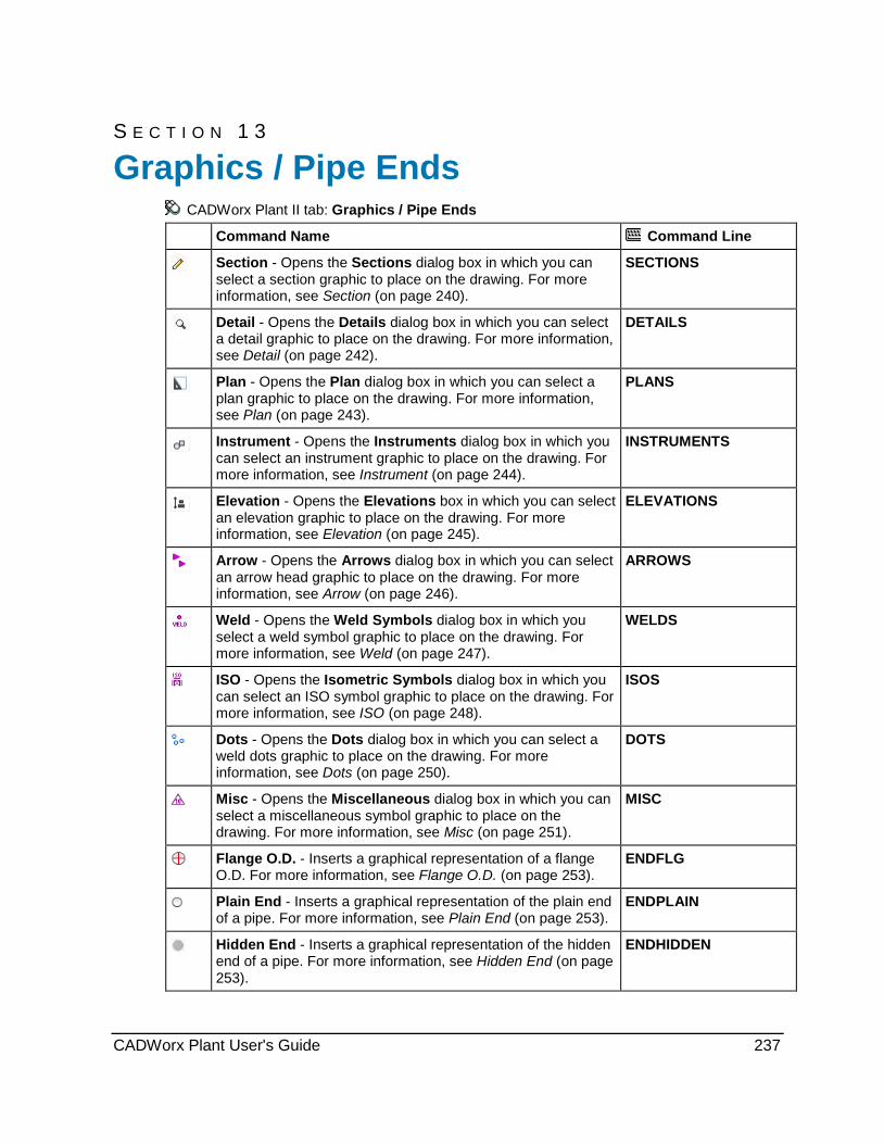
S E C T I O N 1 3
CADWorx Plant II tab: Graphics / Pipe Ends
Command Name Command Line
Section - Opens the Sections dialog box in which you can select a section graphic to place on the drawing. For more information, see Section (on page 240).
SECTIONS
Detail - Opens the Details dialog box in which you can select a detail graphic to place on the drawing. For more information, see Detail (on page 242).
DETAILS
Plan - Opens the Plan dialog box in which you can select a plan graphic to place on the drawing. For more information, see Plan (on page 243).
PLANS
Instrument - Opens the Instruments dialog box in which you can select an instrument graphic to place on the drawing. For more information, see Instrument (on page 244).
INSTRUMENTS
Elevation - Opens the Elevations box in which you can select an elevation graphic to place on the drawing. For more information, see Elevation (on page 245).
ELEVATIONS
Arrow - Opens the Arrows dialog box in which you can select an arrow head graphic to place on the drawing. For more information, see Arrow (on page 246).
ARROWS
Weld - Opens the Weld Symbols dialog box in which you select a weld symbol graphic to place on the drawing. For more information, see Weld (on page 247).
WELDS
ISO - Opens the Isometric Symbols dialog box in which you can select an ISO symbol graphic to place on the drawing. For more information, see ISO (on page 248).
ISOS
Dots - Opens the Dots dialog box in which you can select a weld dots graphic to place on the drawing. For more information, see Dots (on page 250).
DOTS
Misc - Opens the Miscellaneous dialog box in which you can select a miscellaneous symbol graphic to place on the drawing. For more information, see Misc (on page 251).
MISC
Flange O.D. - Inserts a graphical representation of a flange O.D. For more information, see Flange O.D. (on page 253).
ENDFLG
Plain End - Inserts a graphical representation of the plain end of a pipe. For more information, see Plain End (on page 253).
ENDPLAIN
Hidden End - Inserts a graphical representation of the hidden end of a pipe. For more information, see Hidden End (on page 253).
ENDHIDDEN
Graphics / Pipe Ends
CADWorx Plant User's Guide 237
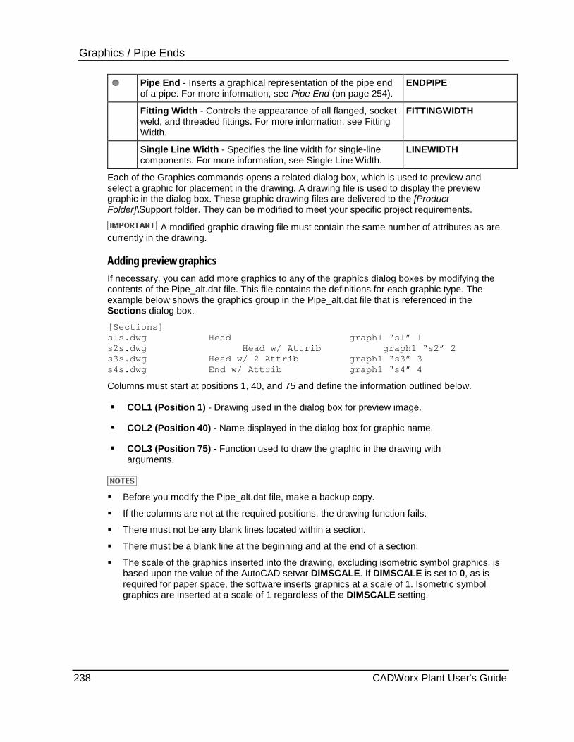
Graphics / Pipe Ends
Pipe End - Inserts a graphical representation of the pipe end of a pipe. For more information, see Pipe End (on page 254).
ENDPIPE
Fitting Width - Controls the appearance of all flanged, socket weld, and threaded fittings. For more information, see Fitting Width.
FITTINGWIDTH
Single Line Width - Specifies the line width for single-line components. For more information, see Single Line Width.
LINEWIDTH
Each of the Graphics commands opens a related dialog box, which is used to preview and select a graphic for placement in the drawing. A drawing file is used to display the preview graphic in the dialog box. These graphic drawing files are delivered to the [Product Folder]\Support folder. They can be modified to meet your specific project requirements.
A modified graphic drawing file must contain the same number of attributes as are currently in the drawing.
Adding preview graphics If necessary, you can add more graphics to any of the graphics dialog boxes by modifying the contents of the Pipe_alt.dat file. This file contains the definitions for each graphic type. The example below shows the graphics group in the Pipe_alt.dat file that is referenced in the Sections dialog box.
[Sections] s1s.dwg Head graph1 “s1” 1 s2s.dwg Head w/ Attrib graph1 “s2” 2 s3s.dwg Head w/ 2 Attrib graph1 “s3” 3 s4s.dwg End w/ Attrib graph1 “s4” 4
Columns must start at positions 1, 40, and 75 and define the information outlined below.
COL1 (Position 1) - Drawing used in the dialog box for preview image.
COL2 (Position 40) - Name displayed in the dialog box for graphic name.
COL3 (Position 75) - Function used to draw the graphic in the drawing with arguments.
Before you modify the Pipe_alt.dat file, make a backup copy.
If the columns are not at the required positions, the drawing function fails.
There must not be any blank lines located within a section.
There must be a blank line at the beginning and at the end of a section.
The scale of the graphics inserted into the drawing, excluding isometric symbol graphics, is based upon the value of the AutoCAD setvar DIMSCALE. If DIMSCALE is set to 0, as is required for paper space, the software inserts graphics at a scale of 1. Isometric symbol graphics are inserted at a scale of 1 regardless of the DIMSCALE setting.
238 CADWorx Plant User's Guide

Graphics / Pipe Ends
System Prompts The system prompts required to draw the graphic types delivered with the software are outlined in the table below.
Function System Response
Prompt 1 Pick left justified insertion point: pick a point in the drawing Rotation angle: pick a direction or enter angle Enter scale: type a string on the command line, and press ENTER
Prompt 2 Pick left justified insertion point: pick point in the drawing Rotation angle: pick direction or enter angle Enter mark: type a string on the command line, and press ENTER Enter scale: type a string on the command line, and press ENTER
Prompt 3 Pick left justified insertion point: pick a point in the drawing Rotation angle: pick a direction in the drawing or enter angle Enter mark: type a string on the command line, and press ENTER (ex: A) Enter drawing: type a string on the command line, and press ENTER (ex: 106) Enter scale: type a string on the command line, and press ENTER (ex: 3/8"=1'-0")
Prompt 4 Pick insertion point: pick a point in the drawing Section direction: pick a direction in the drawing Projection direction: pick a direction in the drawing Enter mark: type a string on the command line, and press ENTER (ex: A)
Prompt 5 Pick insertion point: pick a point in the drawing Section direction: pick a direction in the drawing Projection direction: pick a direction in the drawing Enter mark: type a string on the command line, and press ENTER (ex: A) Enter drawing: type a string on the command line, and press ENTER ( ex: 106)
Prompt 6 Pick insertion point: pick a point in the drawing Section direction: pick a direction in the drawing Projection or other direction: pick a direction in the drawing
Prompt 7 Pick object to mark: pick an object in the drawing Pick mark location: pick point in the drawing Enter mark: type a string on the command line, and press ENTER (ex: A)
Prompt 8 Pick object to mark: pick an object in the drawing Pick mark location: pick a point in the drawing Enter mark: type a string on the command line, and press ENTER (ex: A) Enter drawing: type a string on the command line, and press ENTER (ex: 106)
Prompt 9 Pick left end point: pick a point in the drawing Pick right end point: pick a point in the drawing Enter title: type a string on the command line, and press ENTER (ex: ELEVATION NORTH) Enter scale: enter a string (ex: 3/8"=1'-0")
Prompt 10 Pick instrument to label: pick a point in the drawing Pick mark location: pick a point in the drawing Enter first level label: type a string on the command line, and press ENTER (ex: SDV) Enter second level label: type a string on the command line, and press ENTER (ex: 1)
CADWorx Plant User's Guide 239

Graphics / Pipe Ends Function System Response
Prompt 11 Pick instrument to label: pick a point in the drawing Pick mark location: pick a point in the drawing Enter first level label: type a string on the command line, and press ENTER (ex: PI) Enter second level label: type a string on the command line, and press ENTER (ex: 106) Enter third level label: type a string on the command line, and press ENTER (ex: B)
Prompt 12 Pick center insertion point: pick a point in the drawing Rotation angle: pick a direction or enter angle
Prompt 13 Pick center insertion point: pick a point in the drawing
Prompt 14 Pick center insertion point: pick a point in the drawing Pick direction: pick a direction
Prompt 15 Pick insertion point: pick a point in the drawing (not center insertion, outside edge) Pick direction: pick a direction in the drawing Enter mark: type a string on the command line, and press ENTER (ex: 101)Weld
Prompt 16 Pick leader start point: pick a point in the drawing Pick intermediate point: pick a point in the drawing Pick direction for tail: pick a direction in the drawing
Prompt 17 Pick insertion point: pick a point in the drawing Pick rotation: pick a direction in the drawing
Prompt 18 Pick insertion point: pick a point in the drawing
Prompt 19 Pick insertion point on line: pick a point in the drawing Pick rotation: pick a direction in the drawing
Prompt 20 Pick location: pick a point in the drawing Pick rotation or [Up/Down/Roll/mirrorX/mirrorY/mirrorZ]: select an option or pick the rotation
Section CADWorx Plant II tab: Section
Pipe menu: Graphics > Section
Command line: SECTIONS
Opens the Sections dialog box, which allows you to select a section graphic for placement in the drawing.
Sections Dialog Box Displays the sections graphics that are currently defined in the software.
Preview - Displays a graphical representation of the selected graphic.
Each section graphic is based on an AutoCAD drawing file. Graphics drawing files are delivered to [Product Folder]\Support. You can modify any graphical representation to fit your specific project requirements. You can also create additional graphics, and add them to the dialog box. For more information, see Graphics / Pipe Ends (on page 237).
240 CADWorx Plant User's Guide

Graphics / Pipe Ends The table below lists the section graphics that display in the Sections dialog box by default. The table also includes the name of the AutoCAD drawing that defines the graphical representation, as well as the name of the function used for placement. Each function carries with it a specific set of prompts that you must follow to place the specific graphic in the drawing. For more information, see System Prompts (on page 239).
Sections Graphic Name AutoCAD Drawing Name Function Name
Head S1S.dwg Prompt 1
Head w/ Attrib S2S.dwg Prompt 2
Head w/ 2Attrib S3S.dwg Prompt 3
End w/ Attrib S4S.dwg Prompt 4
End w 2Attrib S5S.dwg Prompt 5
End S6S.dwg Prompt 6
Middle S7S.dwg Prompt 6
Place a section graphic 1. Click Section . Alternatively, type SECTIONS on the command line and then press
ENTER.
The Sections dialog box appears.
2. Select the required graphic in the list.
The Preview box shows a graphical representation of the selected graphic.
3. Click OK to close the dialog box, and return to the drawing.
4. Follow the system prompts to define the placement of the selected graphic in the current drawing.
The system prompts vary depending on the graphic you have selected.
CADWorx Plant User's Guide 241
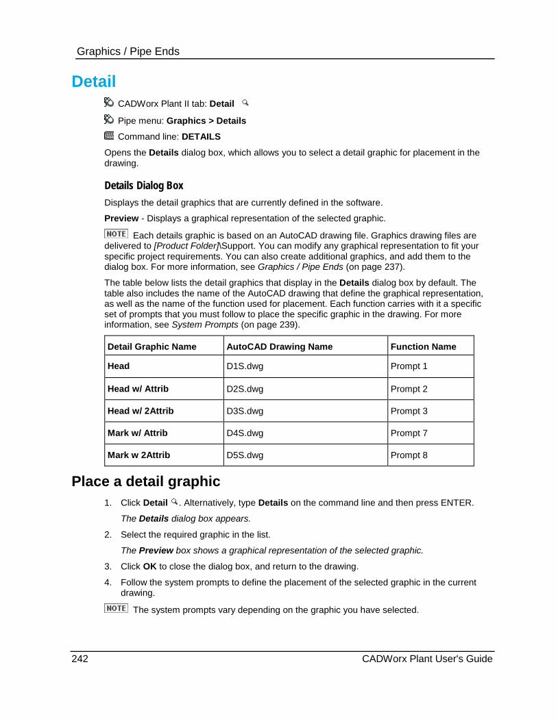
Graphics / Pipe Ends
Detail CADWorx Plant II tab: Detail
Pipe menu: Graphics > Details
Command line: DETAILS
Opens the Details dialog box, which allows you to select a detail graphic for placement in the drawing.
Details Dialog Box Displays the detail graphics that are currently defined in the software.
Preview - Displays a graphical representation of the selected graphic.
Each details graphic is based on an AutoCAD drawing file. Graphics drawing files are delivered to [Product Folder]\Support. You can modify any graphical representation to fit your specific project requirements. You can also create additional graphics, and add them to the dialog box. For more information, see Graphics / Pipe Ends (on page 237).
The table below lists the detail graphics that display in the Details dialog box by default. The table also includes the name of the AutoCAD drawing that define the graphical representation, as well as the name of the function used for placement. Each function carries with it a specific set of prompts that you must follow to place the specific graphic in the drawing. For more information, see System Prompts (on page 239).
Detail Graphic Name AutoCAD Drawing Name Function Name
Head D1S.dwg Prompt 1
Head w/ Attrib D2S.dwg Prompt 2
Head w/ 2Attrib D3S.dwg Prompt 3
Mark w/ Attrib D4S.dwg Prompt 7
Mark w 2Attrib D5S.dwg Prompt 8
Place a detail graphic 1. Click Detail . Alternatively, type Details on the command line and then press ENTER.
The Details dialog box appears.
2. Select the required graphic in the list.
The Preview box shows a graphical representation of the selected graphic.
3. Click OK to close the dialog box, and return to the drawing.
4. Follow the system prompts to define the placement of the selected graphic in the current drawing.
The system prompts vary depending on the graphic you have selected.
242 CADWorx Plant User's Guide
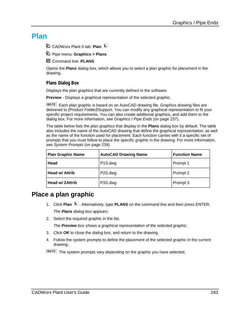
Graphics / Pipe Ends
Plan CADWorx Plant II tab: Plan
Pipe menu: Graphics > Plans
Command line: PLANS
Opens the Plans dialog box, which allows you to select a plan graphic for placement in the drawing.
Plans Dialog Box Displays the plan graphics that are currently defined in the software.
Preview - Displays a graphical representation of the selected graphic.
Each plan graphic is based on an AutoCAD drawing file. Graphics drawing files are delivered to [Product Folder]\Support. You can modify any graphical representation to fit your specific project requirements. You can also create additional graphics, and add them to the dialog box. For more information, see Graphics / Pipe Ends (on page 237).
The table below lists the plan graphics that display in the Plans dialog box by default. The table also includes the name of the AutoCAD drawing that define the graphical representation, as well as the name of the function used for placement. Each function carries with it a specific set of prompts that you must follow to place the specific graphic in the drawing. For more information, see System Prompts (on page 239).
Plan Graphic Name AutoCAD Drawing Name Function Name
Head P1S.dwg Prompt 1
Head w/ Attrib P2S.dwg Prompt 2
Head w/ 2Attrib P3S.dwg Prompt 3
Place a plan graphic 1. Click Plan . Alternatively, type PLANS on the command line and then press ENTER.
The Plans dialog box appears.
2. Select the required graphic in the list.
The Preview box shows a graphical representation of the selected graphic.
3. Click OK to close the dialog box, and return to the drawing.
4. Follow the system prompts to define the placement of the selected graphic in the current drawing.
The system prompts vary depending on the graphic you have selected.
CADWorx Plant User's Guide 243
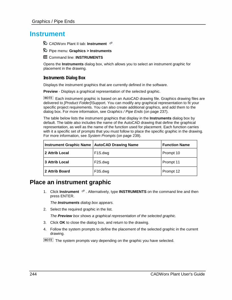
Graphics / Pipe Ends
Instrument CADWorx Plant II tab: Instrument
Pipe menu: Graphics > Instruments
Command line: INSTRUMENTS
Opens the Instruments dialog box, which allows you to select an instrument graphic for placement in the drawing.
Instruments Dialog Box Displays the instrument graphics that are currently defined in the software.
Preview - Displays a graphical representation of the selected graphic.
Each instrument graphic is based on an AutoCAD drawing file. Graphics drawing files are delivered to [Product Folder]\Support. You can modify any graphical representation to fit your specific project requirements. You can also create additional graphics, and add them to the dialog box. For more information, see Graphics / Pipe Ends (on page 237).
The table below lists the instrument graphics that display in the Instruments dialog box by default. The table also includes the name of the AutoCAD drawing that define the graphical representation, as well as the name of the function used for placement. Each function carries with it a specific set of prompts that you must follow to place the specific graphic in the drawing. For more information, see System Prompts (on page 239).
Instrument Graphic Name AutoCAD Drawing Name Function Name
2 Attrib Local F1S.dwg Prompt 10
3 Attrib Local F2S.dwg Prompt 11
2 Attrib Board F3S.dwg Prompt 12
Place an instrument graphic 1. Click Instrument . Alternatively, type INSTRUMENTS on the command line and then
press ENTER.
The Instruments dialog box appears.
2. Select the required graphic in the list.
The Preview box shows a graphical representation of the selected graphic.
3. Click OK to close the dialog box, and return to the drawing.
4. Follow the system prompts to define the placement of the selected graphic in the current drawing.
The system prompts vary depending on the graphic you have selected.
244 CADWorx Plant User's Guide
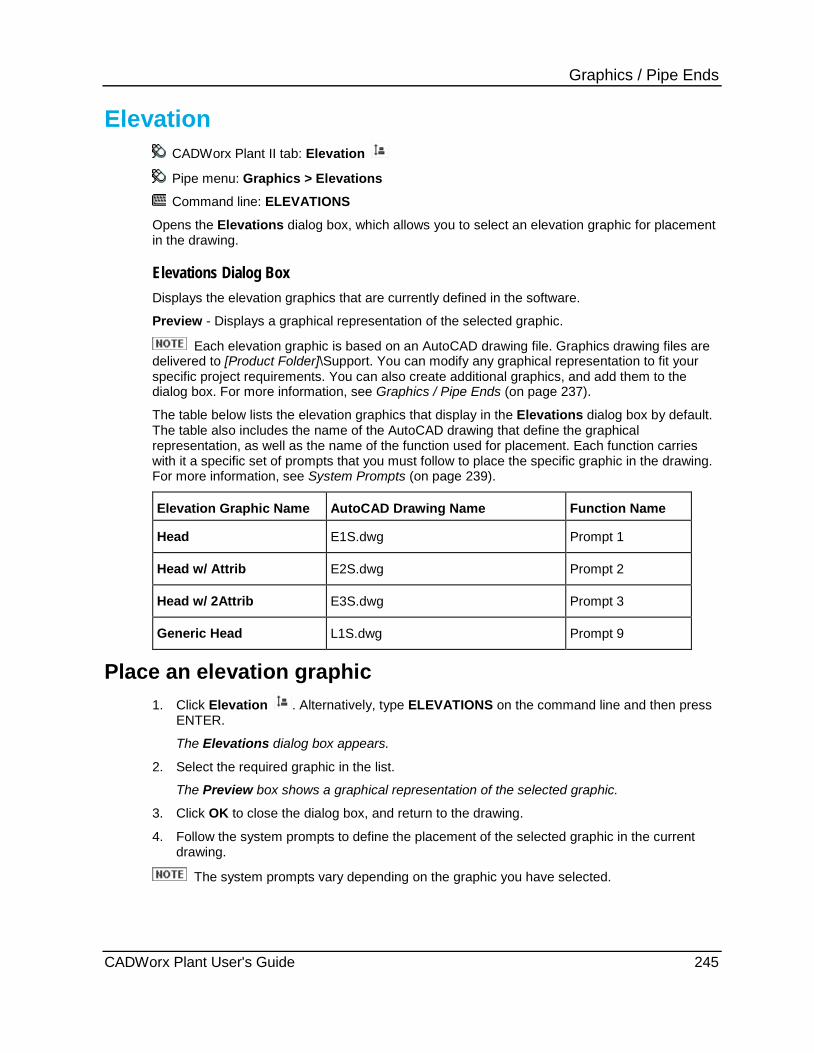
Graphics / Pipe Ends
Elevation CADWorx Plant II tab: Elevation
Pipe menu: Graphics > Elevations
Command line: ELEVATIONS
Opens the Elevations dialog box, which allows you to select an elevation graphic for placement in the drawing.
Elevations Dialog Box Displays the elevation graphics that are currently defined in the software.
Preview - Displays a graphical representation of the selected graphic.
Each elevation graphic is based on an AutoCAD drawing file. Graphics drawing files are delivered to [Product Folder]\Support. You can modify any graphical representation to fit your specific project requirements. You can also create additional graphics, and add them to the dialog box. For more information, see Graphics / Pipe Ends (on page 237).
The table below lists the elevation graphics that display in the Elevations dialog box by default. The table also includes the name of the AutoCAD drawing that define the graphical representation, as well as the name of the function used for placement. Each function carries with it a specific set of prompts that you must follow to place the specific graphic in the drawing. For more information, see System Prompts (on page 239).
Elevation Graphic Name AutoCAD Drawing Name Function Name
Head E1S.dwg Prompt 1
Head w/ Attrib E2S.dwg Prompt 2
Head w/ 2Attrib E3S.dwg Prompt 3
Generic Head L1S.dwg Prompt 9
Place an elevation graphic 1. Click Elevation . Alternatively, type ELEVATIONS on the command line and then press
ENTER.
The Elevations dialog box appears.
2. Select the required graphic in the list.
The Preview box shows a graphical representation of the selected graphic.
3. Click OK to close the dialog box, and return to the drawing.
4. Follow the system prompts to define the placement of the selected graphic in the current drawing.
The system prompts vary depending on the graphic you have selected.
CADWorx Plant User's Guide 245

Graphics / Pipe Ends
Arrow CADWorx Plant II tab: Arrow Pipe menu: Graphics > Arrows Command line: ARROWS
Opens the Arrows dialog box, which allows you to select an arrow head graphic for placement in the drawing.
Arrows Dialog Box Displays the arrow head graphics that are currently defined in the software. Preview - Displays a graphical representation of the selected graphic.
Each arrow head graphic is based on an AutoCAD drawing file. Graphics drawing files are delivered to [Product Folder]\Support. You can modify any graphical representation to fit your specific project requirements. You can also create additional graphics, and add them to the dialog box. For more information, see Graphics / Pipe Ends (on page 237). The table below lists the arrow head graphics that display in the Arrows dialog box by default. The table also includes the name of the AutoCAD drawing that defines the graphical representation, as well as the name of the function used for placement. Each function carries with it a specific set of prompts that you must follow to place the specific graphic in the drawing. For more information, see System Prompts (on page 239).
Arrow Graphic Name AutoCAD Drawing Name Function Name
North N1S.dwg Prompt 14
Prevailing N2S.dwg Prompt 12
Model Iso North N3S.dwg Prompt 12
Paper Iso North N4S.dwg Prompt 14
Small A1S.dwg Prompt 12
Medium A2S.dwg Prompt 12
Large A3S.dwg Prompt 12
Place an arrow head graphic 1. Click Arrow . Alternatively, type ARROWS on the command line and then press ENTER.
The Arrows dialog box appears. 2. Select the required graphic in the list.
The Preview box shows a graphical representation of the selected graphic. 3. Click OK to close the dialog box, and return to the drawing. 4. Follow the system prompts to define the placement of the selected graphic in the current
drawing. The system prompts vary depending on the graphic you have selected.
246 CADWorx Plant User's Guide

Graphics / Pipe Ends
Weld CADWorx Plant II tab: Weld
Pipe menu: Graphics > Weld
Command line: WELDS
Opens the Weld Symbols dialog box, which allows you to select a weld symbol graphic for placement in the drawing.
Weld Symbols Dialog Box Displays the weld symbol graphics that are currently defined in the software.
Preview - Displays a graphical representation of the selected graphic.
Each weld symbol graphic is based on an AutoCAD drawing file. Graphics drawing files are delivered to [Product Folder]\Support. You can modify any graphical representation to fit your specific project requirements. You can also create additional graphics, and add them to the dialog box. For more information, see Graphics / Pipe Ends (on page 237).
The table below lists the weld symbol graphics that display in the Weld Symbols dialog box by default. The table also includes the name of the AutoCAD drawing that defines the graphical representation, as well as the name of the function used for placement. Each function carries with it a specific set of prompts that you must follow to place the specific graphic in the drawing. For more information, see System Prompts (on page 239).
Weld Symbol Graphic Name AutoCAD Drawing Name Function Name
Leader W1X.dwg Prompt 16
Fillet W2X.dwg Prompt 17
Weld Around W3X.dwg Prompt 18
Field Weld W4X.dwg Prompt 17
Back W5X.dwg Prompt 17
Square W6X.dwg Prompt 17
V Groove W7X.dwg Prompt 17
Bevel W8X.dwg Prompt 17
U Groove W9X.dwg Prompt 17
J Groove W10X.dwg Prompt 17
V Flare W11X.dwg Prompt 17
Flare Bevel W12X.dwg Prompt 17
CADWorx Plant User's Guide 247
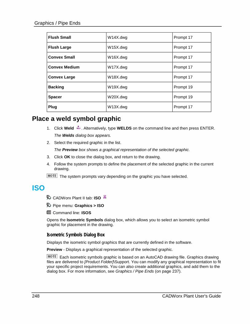
Graphics / Pipe Ends Flush Small W14X.dwg Prompt 17
Flush Large W15X.dwg Prompt 17
Convex Small W16X.dwg Prompt 17
Convex Medium W17X.dwg Prompt 17
Convex Large W18X.dwg Prompt 17
Backing W19X.dwg Prompt 19
Spacer W20X.dwg Prompt 19
Plug W13X.dwg Prompt 17
Place a weld symbol graphic 1. Click Weld . Alternatively, type WELDS on the command line and then press ENTER.
The Welds dialog box appears.
2. Select the required graphic in the list.
The Preview box shows a graphical representation of the selected graphic.
3. Click OK to close the dialog box, and return to the drawing.
4. Follow the system prompts to define the placement of the selected graphic in the current drawing.
The system prompts vary depending on the graphic you have selected.
ISO CADWorx Plant II tab: ISO
Pipe menu: Graphics > ISO
Command line: ISOS
Opens the Isometric Symbols dialog box, which allows you to select an isometric symbol graphic for placement in the drawing.
Isometric Symbols Dialog Box Displays the isometric symbol graphics that are currently defined in the software.
Preview - Displays a graphical representation of the selected graphic.
Each isometric symbols graphic is based on an AutoCAD drawing file. Graphics drawing files are delivered to [Product Folder]\Support. You can modify any graphical representation to fit your specific project requirements. You can also create additional graphics, and add them to the dialog box. For more information, see Graphics / Pipe Ends (on page 237).
248 CADWorx Plant User's Guide
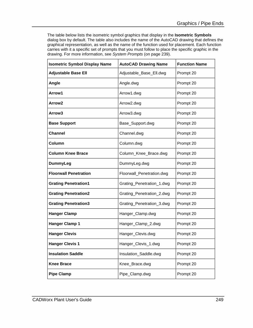
Graphics / Pipe Ends The table below lists the isometric symbol graphics that display in the Isometric Symbols dialog box by default. The table also includes the name of the AutoCAD drawing that defines the graphical representation, as well as the name of the function used for placement. Each function carries with it a specific set of prompts that you must follow to place the specific graphic in the drawing. For more information, see System Prompts (on page 239).
Isometric Symbol Display Name AutoCAD Drawing Name Function Name
Adjustable Base Ell Adjustable_Base_Ell.dwg Prompt 20
Angle Angle.dwg Prompt 20
Arrow1 Arrow1.dwg Prompt 20
Arrow2 Arrow2.dwg Prompt 20
Arrow3 Arrow3.dwg Prompt 20
Base Support Base_Support.dwg Prompt 20
Channel Channel.dwg Prompt 20
Column Column.dwg Prompt 20
Column Knee Brace Column_Knee_Brace.dwg Prompt 20
DummyLeg DummyLeg.dwg Prompt 20
Floorwall Penetration Floorwall_Penetration.dwg Prompt 20
Grating Penetration1 Grating_Penetration_1.dwg Prompt 20
Grating Penetration2 Grating_Penetration_2.dwg Prompt 20
Grating Penetration3 Grating_Penetration_3.dwg Prompt 20
Hanger Clamp Hanger_Clamp.dwg Prompt 20
Hanger Clamp 1 Hanger_Clamp_2.dwg Prompt 20
Hanger Clevis Hanger_Clevis.dwg Prompt 20
Hanger Clevis 1 Hanger_Clevis_1.dwg Prompt 20
Insulation Saddle Insulation_Saddle.dwg Prompt 20
Knee Brace Knee_Brace.dwg Prompt 20
Pipe Clamp Pipe_Clamp.dwg Prompt 20
CADWorx Plant User's Guide 249

Graphics / Pipe Ends Pipe Shoe Extrude Pipe_Shoe_Extrude.dwg Prompt 20
Pipe Shoe Faced Pipe_Shoe_Faced.dwg Prompt 20
Spring Hanger Clamp Spring_Hanger_Clamp.dwg Prompt 20
T Support T_Support.dwg Prompt 20
Ubolt Ubolt.dwg Prompt 20
Ubolt 1 Ubolt_2.dwg Prompt 20
Wide Flange Beam WFlange_Beam.dwg Prompt 20
Place an isometric symbol graphic 1. Click ISO . Alternatively, type ISOS on the command line and then press ENTER.
The Isometric Symbol dialog box appears.
2. Select the required graphic in the list.
The Preview box shows a graphical representation of the selected graphic.
3. Click OK to close the dialog box, and return to the drawing.
4. Follow the system prompts to define the placement of the selected graphic in the current drawing.
The system prompts vary depending on the graphic you have selected.
Dots CADWorx Plant II tab: Dots
Pipe menu: Graphics > Dots
Command line: DOTS
Opens the Dots dialog box, which allows you to select a weld dot graphic for placement in the drawing.
Dots Dialog Box Displays the weld dot graphics that are currently defined in the software.
Preview - Displays a graphical representation of the selected graphic.
Each weld dot graphic is based on an AutoCAD drawing file. Graphics drawing files are delivered to [Product Folder]\Support. You can modify any graphical representation to fit your specific project requirements. You can also create additional graphics, and add them to the dialog box. For more information, see Graphics / Pipe Ends (on page 237).
250 CADWorx Plant User's Guide
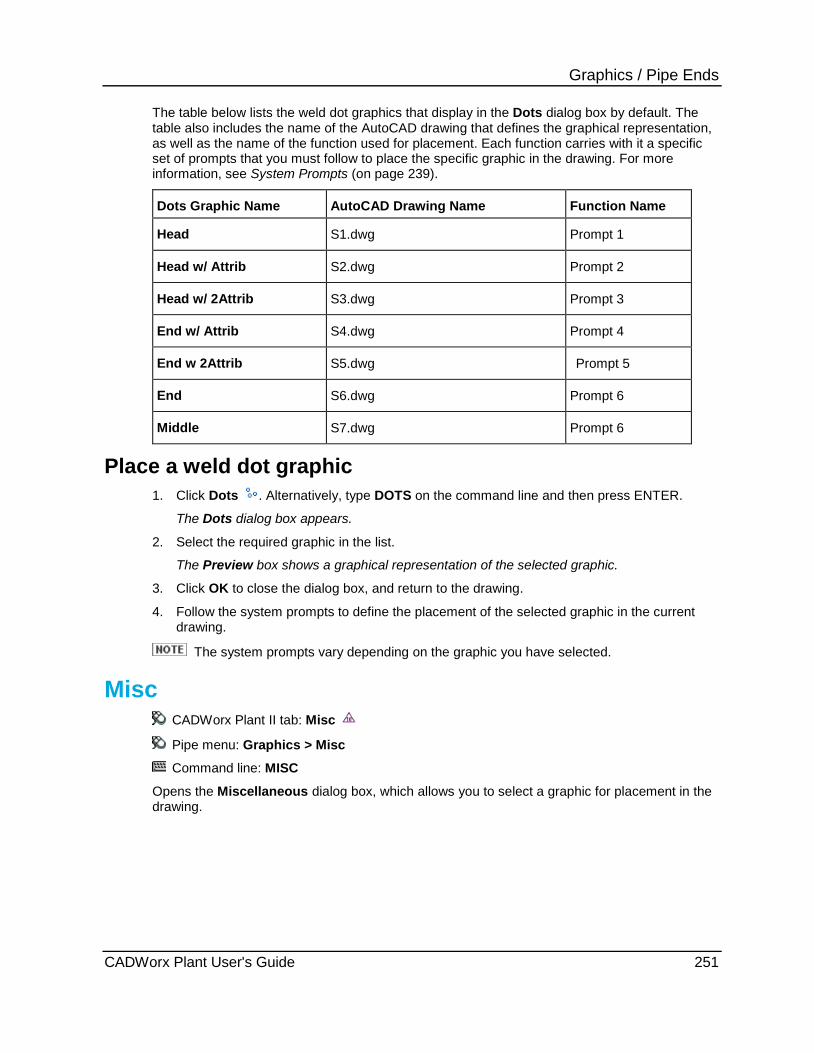
Graphics / Pipe Ends The table below lists the weld dot graphics that display in the Dots dialog box by default. The table also includes the name of the AutoCAD drawing that defines the graphical representation, as well as the name of the function used for placement. Each function carries with it a specific set of prompts that you must follow to place the specific graphic in the drawing. For more information, see System Prompts (on page 239).
Dots Graphic Name AutoCAD Drawing Name Function Name
Head S1.dwg Prompt 1
Head w/ Attrib S2.dwg Prompt 2
Head w/ 2Attrib S3.dwg Prompt 3
End w/ Attrib S4.dwg Prompt 4
End w 2Attrib S5.dwg Prompt 5
End S6.dwg Prompt 6
Middle S7.dwg Prompt 6
Place a weld dot graphic 1. Click Dots . Alternatively, type DOTS on the command line and then press ENTER.
The Dots dialog box appears.
2. Select the required graphic in the list.
The Preview box shows a graphical representation of the selected graphic.
3. Click OK to close the dialog box, and return to the drawing.
4. Follow the system prompts to define the placement of the selected graphic in the current drawing.
The system prompts vary depending on the graphic you have selected.
Misc CADWorx Plant II tab: Misc
Pipe menu: Graphics > Misc
Command line: MISC
Opens the Miscellaneous dialog box, which allows you to select a graphic for placement in the drawing.
CADWorx Plant User's Guide 251
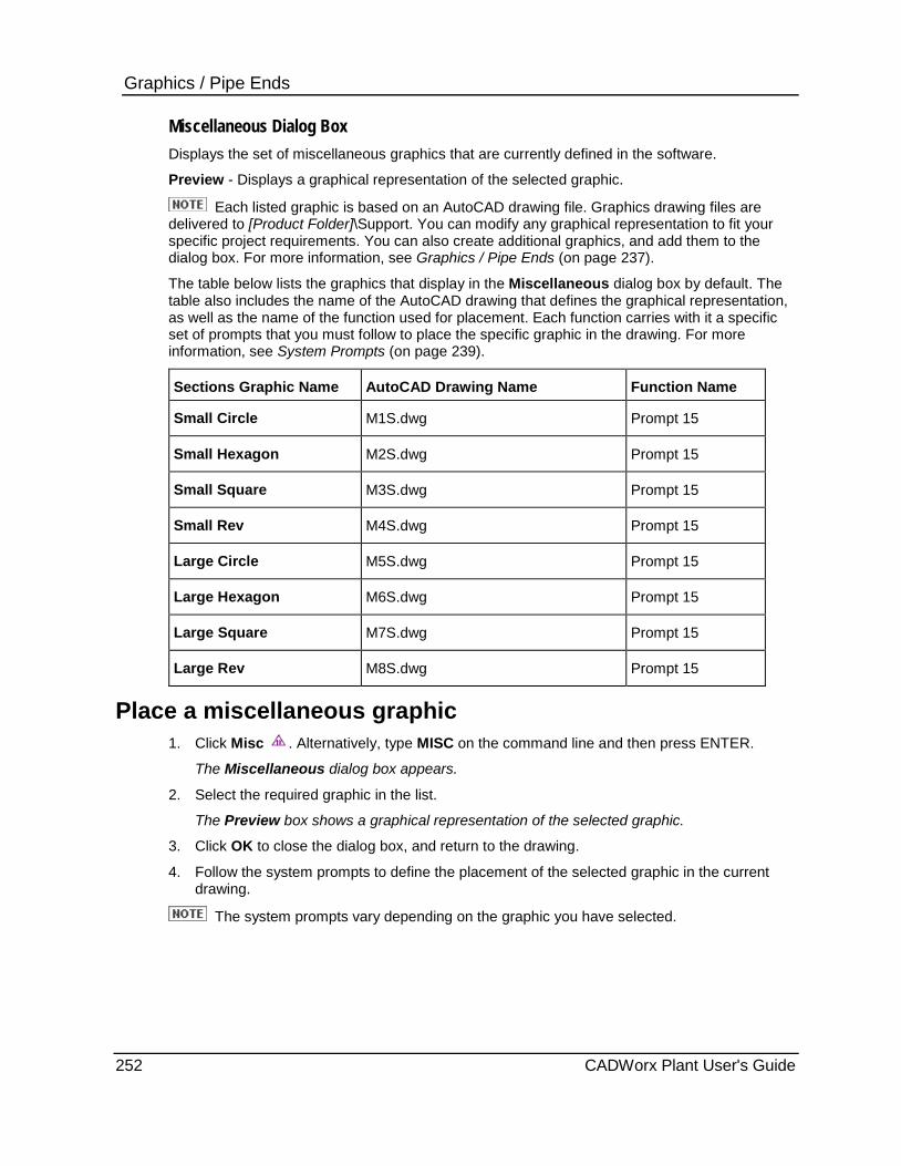
Graphics / Pipe Ends Miscellaneous Dialog Box Displays the set of miscellaneous graphics that are currently defined in the software.
Preview - Displays a graphical representation of the selected graphic.
Each listed graphic is based on an AutoCAD drawing file. Graphics drawing files are delivered to [Product Folder]\Support. You can modify any graphical representation to fit your specific project requirements. You can also create additional graphics, and add them to the dialog box. For more information, see Graphics / Pipe Ends (on page 237).
The table below lists the graphics that display in the Miscellaneous dialog box by default. The table also includes the name of the AutoCAD drawing that defines the graphical representation, as well as the name of the function used for placement. Each function carries with it a specific set of prompts that you must follow to place the specific graphic in the drawing. For more information, see System Prompts (on page 239).
Sections Graphic Name AutoCAD Drawing Name Function Name
Small Circle M1S.dwg Prompt 15
Small Hexagon M2S.dwg Prompt 15
Small Square M3S.dwg Prompt 15
Small Rev M4S.dwg Prompt 15
Large Circle M5S.dwg Prompt 15
Large Hexagon M6S.dwg Prompt 15
Large Square M7S.dwg Prompt 15
Large Rev M8S.dwg Prompt 15
Place a miscellaneous graphic 1. Click Misc . Alternatively, type MISC on the command line and then press ENTER.
The Miscellaneous dialog box appears.
2. Select the required graphic in the list.
The Preview box shows a graphical representation of the selected graphic.
3. Click OK to close the dialog box, and return to the drawing.
4. Follow the system prompts to define the placement of the selected graphic in the current drawing.
The system prompts vary depending on the graphic you have selected.
252 CADWorx Plant User's Guide
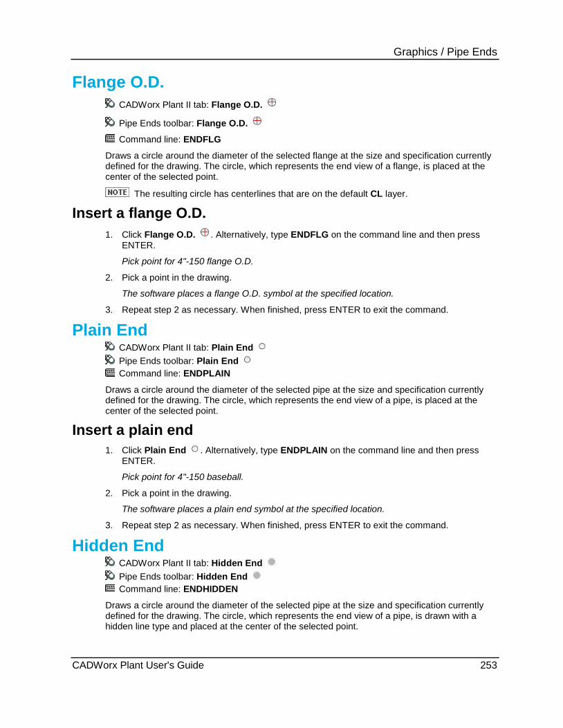
Graphics / Pipe Ends
Flange O.D. CADWorx Plant II tab: Flange O.D.
Pipe Ends toolbar: Flange O.D.
Command line: ENDFLG
Draws a circle around the diameter of the selected flange at the size and specification currently defined for the drawing. The circle, which represents the end view of a flange, is placed at the center of the selected point.
The resulting circle has centerlines that are on the default CL layer.
Insert a flange O.D. 1. Click Flange O.D. . Alternatively, type ENDFLG on the command line and then press
ENTER.
Pick point for 4"-150 flange O.D.
2. Pick a point in the drawing.
The software places a flange O.D. symbol at the specified location.
3. Repeat step 2 as necessary. When finished, press ENTER to exit the command.
Plain End CADWorx Plant II tab: Plain End Pipe Ends toolbar: Plain End Command line: ENDPLAIN
Draws a circle around the diameter of the selected pipe at the size and specification currently defined for the drawing. The circle, which represents the end view of a pipe, is placed at the center of the selected point.
Insert a plain end 1. Click Plain End . Alternatively, type ENDPLAIN on the command line and then press
ENTER.
Pick point for 4"-150 baseball.
2. Pick a point in the drawing.
The software places a plain end symbol at the specified location.
3. Repeat step 2 as necessary. When finished, press ENTER to exit the command.
Hidden End CADWorx Plant II tab: Hidden End Pipe Ends toolbar: Hidden End Command line: ENDHIDDEN
Draws a circle around the diameter of the selected pipe at the size and specification currently defined for the drawing. The circle, which represents the end view of a pipe, is drawn with a hidden line type and placed at the center of the selected point.
CADWorx Plant User's Guide 253

Graphics / Pipe Ends
Insert a hidden end 1. Click Hidden End . Alternatively, type ENDHIDDEN on the command line and then press
ENTER.
Pick point for 4"-150 baseball.
2. Pick a point in the drawing.
The software places a hidden end symbol at the specified location.
3. Repeat step 2 as necessary. When finished, press ENTER to exit the command.
Pipe End CADWorx Plant II tab: Pipe End
Pipe Ends toolbar: Pipe End
Command line: ENDPIPE
Places a baseball at the center of the selected point. The size and the layer of the baseball are determined by the current defined specification.
Insert a pipe end 1. Click Pipe End . Alternatively, type ENDPIPE on the command line and then press
ENTER.
Pick point for 4"-150 baseball.
2. Pick a point in the drawing.
The software places a pipe end symbol at the specified location.
3. Repeat step 2 as necessary. When finished, press ENTER to exit the command.
254 CADWorx Plant User's Guide
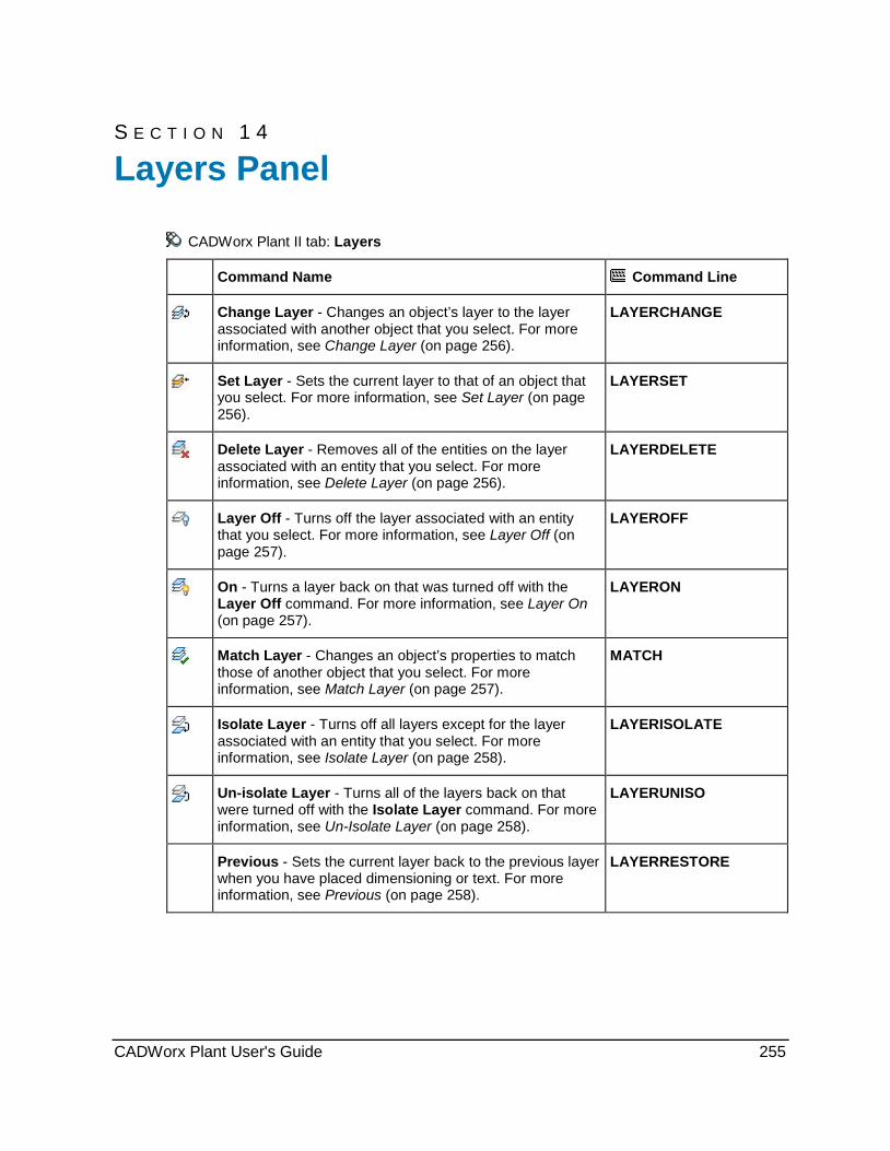
S E C T I O N 1 4
CADWorx Plant II tab: Layers
Command Name Command Line
Change Layer - Changes an object’s layer to the layer associated with another object that you select. For more information, see Change Layer (on page 256).
LAYERCHANGE
Set Layer - Sets the current layer to that of an object that you select. For more information, see Set Layer (on page 256).
LAYERSET
Delete Layer - Removes all of the entities on the layer associated with an entity that you select. For more information, see Delete Layer (on page 256).
LAYERDELETE
Layer Off - Turns off the layer associated with an entity that you select. For more information, see Layer Off (on page 257).
LAYEROFF
On - Turns a layer back on that was turned off with the Layer Off command. For more information, see Layer On (on page 257).
LAYERON
Match Layer - Changes an object’s properties to match those of another object that you select. For more information, see Match Layer (on page 257).
MATCH
Isolate Layer - Turns off all layers except for the layer associated with an entity that you select. For more information, see Isolate Layer (on page 258).
LAYERISOLATE
Un-isolate Layer - Turns all of the layers back on that were turned off with the Isolate Layer command. For more information, see Un-Isolate Layer (on page 258).
LAYERUNISO
Previous - Sets the current layer back to the previous layer when you have placed dimensioning or text. For more information, see Previous (on page 258).
LAYERRESTORE
Layers Panel
CADWorx Plant User's Guide 255
Layers Panel
Change Layer CADWorx Plant II tab: Layers > Change Layer
Plant menu: Utility > Layer Control > Change
Command line: LAYERCHANGE
Changes an object’s layer to the layer associated with another object that you select. You can select the objects to change individually or with a fence.
Change the layer associated with an object 1. Click Change Layer .
2. Select the objects whose layer you want to change.
3. Select additional object to change layers, or press ENTER to end the selection process.
4. Select an object on the layer to which you want to move the objects.
The software moves the selected object to the new layer.
Set Layer CADWorx Plant II tab: Layers > Set Layer
Plant menu: Utility > Layer Control > Set
Command line: LAYERSET
Sets the current layer to that of an object that you select. You must select an individual object.
Set the active layer 1. Click Set Layer .
2. Select the objects whose layer you want to be the active layer.
The software sets the active layer to that of the selected object.
Delete Layer CADWorx Plant II tab: Layers > Delete Layer
Plant menu: Utility > Layer Control > Delete
Command line: LAYERDELETE
Removes all of the entities on the layer associated with an entity that you select. For example, you can delete all the entities, such as lines, text, and so on, on layer 0. You must select an individual entity.
If you select the VIEWL layer, the software displays a warning message. Deleting the VIEWL layer deletes a block named CPM which the software inserts when beginning a new drawing. This block contains information (sizes, specification, and so on) that are used when opening an existing drawing. If you delete this layer, this information is not available for the next drawing session. You can re-enter this information.
256 CADWorx Plant User's Guide
Layers Panel
Delete a layer 1. Click Delete Layer .
2. Select the object whose layer you want to delete.
The software deletes the layer associated with the selected object.
Layer Off CADWorx Plant II tab: Layers > Layer Off
Plant menu: Utility > Layer Control > Off
Command line: LAYEROFF
Turns off the layer associated with an entity that you select. You must select an Individual entity.
Turn off a layer 1. Click Layer Off .
2. Select the object whose layer you want to turn off.
The software turns off the display of the layer associated with the selected object.
Layer On CADWorx Plant II tab: Layers > Layer On Plant menu: Utility > Layer Control > On Command line: LAYERON
Turns a layer back on that was turned off with the Layer Off command. For more information, see Layer Off (on page 257). No selection is required.
Redisplay a layer turned off by the Layer Off command Click Layer On .
The software redisplays the layer.
Match Layer CADWorx Plant II tab: Layers > Match Layer
Plant menu: Utility > Layer Control > Match
Command line: MATCH
Changes an object’s layer to match that of another object that you select.
Match an object's layer 1. Click Match Layer .
2. Select the objects whose layer you want to change. Press ENTER to end the selection.
3. Select an object on the layer that you want to match.
The software changes the layer of the objects.
CADWorx Plant User's Guide 257

Layers Panel
Isolate Layer CADWorx Plant II tab: Layers > Isolate Layer
Plant menu: Utility > Layer Control > Isolate
Command line: LAYERISOLATE
Turns off all layers except for the layer associated with an entity that you select.
Display only the layer associated with an object 1. Click Isolate Layer .
2. Select an object on the layer to isolate.
The software turns off all layers except for the layer associated with the selected object..
Un-Isolate Layer CADWorx Plant II tab: Layers > Un-Isolate Layer
Plant menu: Utility > Layer Control > Un-Isolate
Command line: LAYERUNISO
Turns all of the layers on. No selection is required.
Turn on all layers Click Un-Isolate Layer .
The software turns on display for all layers.
Previous Plant menu: Utility > Layer Control > Previous
Command line: LAYERRESTORE
Sets the current layer back to the previous layer when you have placed dimensioning or text. This command is only available after these two items are placed. This command does not restore a previous layer that has been changed with the Layer or Ddlmodes commands.
258 CADWorx Plant User's Guide
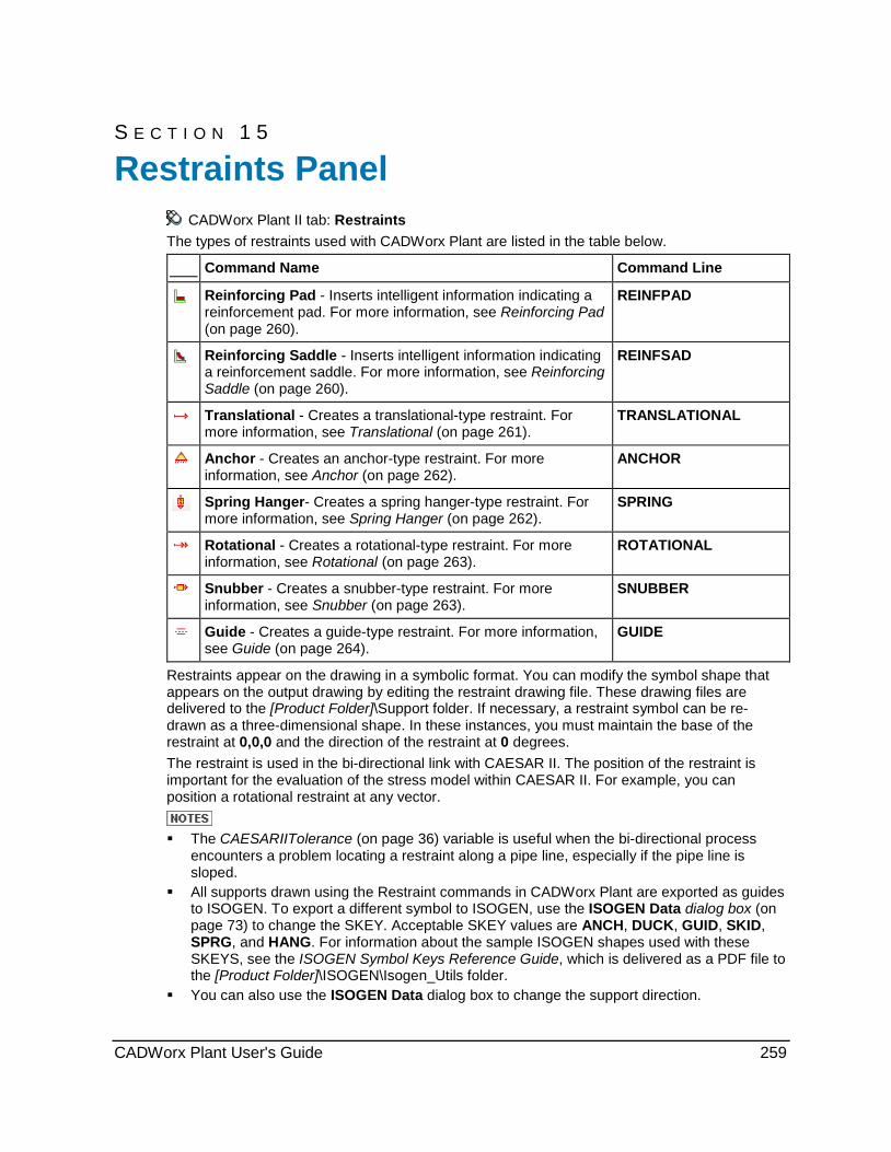
S E C T I O N 1 5
CADWorx Plant II tab: Restraints The types of restraints used with CADWorx Plant are listed in the table below.
Command Name Command Line
Reinforcing Pad - Inserts intelligent information indicating a reinforcement pad. For more information, see Reinforcing Pad (on page 260).
REINFPAD
Reinforcing Saddle - Inserts intelligent information indicating a reinforcement saddle. For more information, see Reinforcing Saddle (on page 260).
REINFSAD
Translational - Creates a translational-type restraint. For more information, see Translational (on page 261).
TRANSLATIONAL
Anchor - Creates an anchor-type restraint. For more information, see Anchor (on page 262).
ANCHOR
Spring Hanger- Creates a spring hanger-type restraint. For more information, see Spring Hanger (on page 262).
SPRING
Rotational - Creates a rotational-type restraint. For more information, see Rotational (on page 263).
ROTATIONAL
Snubber - Creates a snubber-type restraint. For more information, see Snubber (on page 263).
SNUBBER
Guide - Creates a guide-type restraint. For more information, see Guide (on page 264).
GUIDE
Restraints appear on the drawing in a symbolic format. You can modify the symbol shape that appears on the output drawing by editing the restraint drawing file. These drawing files are delivered to the [Product Folder]\Support folder. If necessary, a restraint symbol can be re-drawn as a three-dimensional shape. In these instances, you must maintain the base of the restraint at 0,0,0 and the direction of the restraint at 0 degrees. The restraint is used in the bi-directional link with CAESAR II. The position of the restraint is important for the evaluation of the stress model within CAESAR II. For example, you can position a rotational restraint at any vector.
The CAESARIITolerance (on page 36) variable is useful when the bi-directional process
encounters a problem locating a restraint along a pipe line, especially if the pipe line is sloped.
All supports drawn using the Restraint commands in CADWorx Plant are exported as guides to ISOGEN. To export a different symbol to ISOGEN, use the ISOGEN Data dialog box (on page 73) to change the SKEY. Acceptable SKEY values are ANCH, DUCK, GUID, SKID, SPRG, and HANG. For information about the sample ISOGEN shapes used with these SKEYS, see the ISOGEN Symbol Keys Reference Guide, which is delivered as a PDF file to the [Product Folder]\ISOGEN\Isogen_Utils folder.
You can also use the ISOGEN Data dialog box to change the support direction.
Restraints Panel
CADWorx Plant User's Guide 259
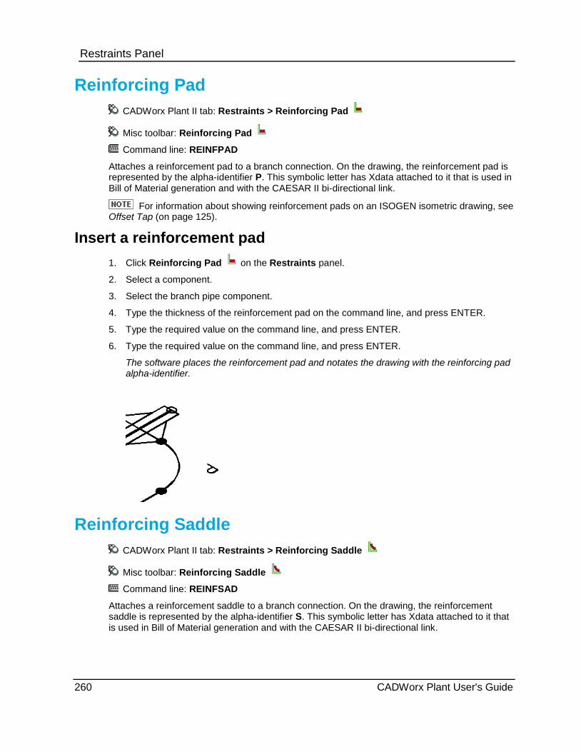
Restraints Panel
Reinforcing Pad CADWorx Plant II tab: Restraints > Reinforcing Pad
Misc toolbar: Reinforcing Pad
Command line: REINFPAD
Attaches a reinforcement pad to a branch connection. On the drawing, the reinforcement pad is represented by the alpha-identifier P. This symbolic letter has Xdata attached to it that is used in Bill of Material generation and with the CAESAR II bi-directional link.
For information about showing reinforcement pads on an ISOGEN isometric drawing, see Offset Tap (on page 125).
Insert a reinforcement pad 1. Click Reinforcing Pad on the Restraints panel.
2. Select a component.
3. Select the branch pipe component.
4. Type the thickness of the reinforcement pad on the command line, and press ENTER.
5. Type the required value on the command line, and press ENTER.
6. Type the required value on the command line, and press ENTER.
The software places the reinforcement pad and notates the drawing with the reinforcing pad alpha-identifier.
Reinforcing Saddle CADWorx Plant II tab: Restraints > Reinforcing Saddle
Misc toolbar: Reinforcing Saddle
Command line: REINFSAD
Attaches a reinforcement saddle to a branch connection. On the drawing, the reinforcement saddle is represented by the alpha-identifier S. This symbolic letter has Xdata attached to it that is used in Bill of Material generation and with the CAESAR II bi-directional link.
260 CADWorx Plant User's Guide

Restraints Panel
Insert a reinforcement saddle 1. Click Reinforcing Saddle on the Restraints panel.
2. Select a component.
3. Select the branch run of the component.
4. Type the thickness of the reinforcement saddle on the command line, and press ENTER.
5. Type the required value on the command line, and press ENTER.
6. Type the required value on the command line, and press ENTER.
The software places the reinforcement saddle and notates the drawing with the reinforcing saddle alpha-identifier.
Translational CADWorx Plant II tab: Restraints > Translational
Restraints toolbar: Translational
Command line: TRANSLATIONAL
Creates a translational-type restraint.
This type of restraint appears on the drawing in a symbolic format.
Place a translational restraint 1. Click Translational on the Restraints panel.
2. Click where you want the transitional placed.
3. Select a direction in the drawing.
4. Type a numerical value on the command line, and press ENTER.
The transitional is placed in the drawing.
CADWorx Plant User's Guide 261
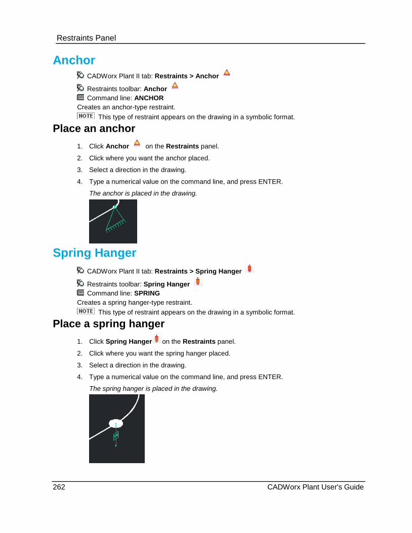
Restraints Panel
Anchor CADWorx Plant II tab: Restraints > Anchor
Restraints toolbar: Anchor Command line: ANCHOR
Creates an anchor-type restraint. This type of restraint appears on the drawing in a symbolic format.
Place an anchor 1. Click Anchor on the Restraints panel.
2. Click where you want the anchor placed.
3. Select a direction in the drawing.
4. Type a numerical value on the command line, and press ENTER.
The anchor is placed in the drawing.
Spring Hanger CADWorx Plant II tab: Restraints > Spring Hanger
Restraints toolbar: Spring Hanger Command line: SPRING
Creates a spring hanger-type restraint. This type of restraint appears on the drawing in a symbolic format.
Place a spring hanger 1. Click Spring Hanger on the Restraints panel.
2. Click where you want the spring hanger placed.
3. Select a direction in the drawing.
4. Type a numerical value on the command line, and press ENTER.
The spring hanger is placed in the drawing.
262 CADWorx Plant User's Guide

Restraints Panel
Rotational CADWorx Plant II tab: Restraints > Rotational
Restraints toolbar: Rotational Command line: ROTATIONAL
Creates a rotational-type restraint. This type of restraint appears on the drawing in a symbolic format.
Place a rotational restraint 1. Click Rotational on the Restraints panel. 2. Click where you want the restraint placed. 3. Select a direction in the drawing. 4. Type a numerical value on the command line, and press ENTER.
The restraint is placed in the drawing.
Snubber CADWorx Plant II tab: Restraints > Snubber Restraints toolbar: Snubber Command line: SNUBBER
Creates a snubber-type restraint. This type of restraint appears on the drawing in a symbolic format.
Place a snubber 1. Click Snubber on the Restraints panel. 2. Click where you want the snubber placed. 3. Select a direction in the drawing. 4. Type a numerical value on the command line, and press ENTER.
The snubber is placed in the drawing.
CADWorx Plant User's Guide 263
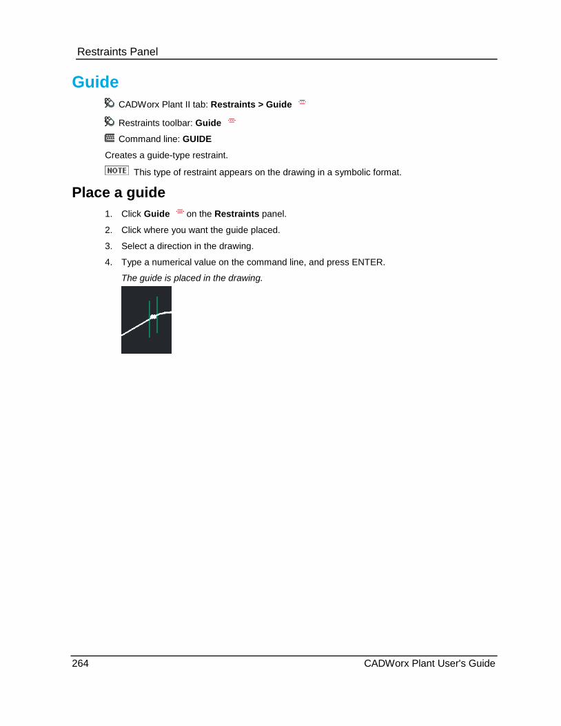
Restraints Panel
Guide CADWorx Plant II tab: Restraints > Guide
Restraints toolbar: Guide
Command line: GUIDE
Creates a guide-type restraint.
This type of restraint appears on the drawing in a symbolic format.
Place a guide 1. Click Guide on the Restraints panel.
2. Click where you want the guide placed.
3. Select a direction in the drawing.
4. Type a numerical value on the command line, and press ENTER.
The guide is placed in the drawing.
264 CADWorx Plant User's Guide

S E C T I O N 1 6
CADWorx Plant II tab: UCS
Command Name Command Line
Flat - Places the current user coordinate system in the flat position. For more information, see Flat (on page 267).
VIEWFLAT
Next - Places the current user coordinate system in the next position. For more information, see UCS Next (on page 268).
UCSNEXT
Compass - Displays a compass-type symbol that indicates the Point and Shoot orientation. For more information, see Compass (on page 268).
COMPASS
North - Places the current user coordinate system in the north position. For more information, see North (on page 268).
VIEWNORTH
South - Places the current user coordinate system in the south position. For more information, see South (on page 269).
VIEWSOUTH
East - Places the current user coordinate system in the east position. For more information, see East (on page 270).
VIEWEAST
West - Places the current user coordinate system in the west position. For more information, see West (on page 269).
VIEWWEST
UCS Object - Orients the current user coordinate system according to an object that you select. For more information, see UCS Object (on page 270).
UCS
Point and Shoot UCS AutoCAD allows you to manipulate the X, Y, Z coordinate system UCS (user coordinate system). You must be familiar with the Point and Shoot system of manipulating the UCS.
The UCSICON option needs to be On (visible) and set to Origin. This lets you see exactly where the icon is at all times. Although it isn’t necessary, it is highly recommended that it be somewhere on the centerline of the components you are drawing. This keeps everything in the same plane. If you must turn into another plane, use the UCS NEXT command, or choose the appropriate plane (North, South, East, West, or Flat) and place the icon on the centerline of the new plane.
UCS Panel
CADWorx Plant User's Guide 265

UCS Panel If you cannot see the rubber band effect, or if it doesn’t appear correctly, you are out of plane. Pay attention to the icon as it shows where you are. If the broken pencil icon appears, and there are strange lines on the screen instead of pipe and components, your current plane is perpendicular to the viewpoint. Use the Undo command, or change the viewpoint.
When dimensioning or annotating an isometric or 3D model, place the UCS icon on a node or a centerline on the run you are working on. The text has the same orientation as the icon.
Xtext - Rotates the UCS 180 degrees along the X-axis. When you view a model from the bottom side using a view point with a negative angle from the X-Y plane, text and dimension placement is upside down and backwards. This option rotates the X-axis of the UCS to remedy this. Text and dimensions are then placed in the proper orientation for viewing and plotting. If you change from a negative to positive angle from the X-Y view point, you must replace the text for the proper orientation.
Ztext - Rotates the UCS 180 degrees along the Z-axis. When viewing a model from the back side using a view point with a 0 to 180 degree angle in the X-Y plane from the X axis, text and dimension placement is upside down and backwards. This option rotates the Z-axis of the UCS to remedy this. Text and dimensions are then placed in the proper orientation for viewing and plotting. If you change to a rear view position (180 - 360 degree angle in the X-Y plane from the X-axis), you must replace the text for the proper orientation.
Elevation - Sets the elevation to the present UCS. This command does not set the depth in a North, South, East, or West plane. Setting an elevation of 10' (when the present elevation is 0') raises the UCS to 10' regardless of the position.
Rotate - Rotates the present UCS around the X-, Y-, and Z-axes. For example, rotating the UCS to 45 degrees after inserting a 45 degree elbow allows you to place other components in line with the 45 degree elbow.
COordinate - Specifies an exact X, Y, Z-coordinate in relation to the WCS (world coordinate system).
CLip - Clips the view at the present plane set by the UCS. This plane can be established with the Point and Shoot UCS options or any three-point UCS position. The plane can be skewed at any angle.
On - Turns on view clipping with clipping distances as set by the Back and Front options.
Off - Turns off view clipping.
Back - Sets the distance to the back of the clipping area. This value must be a negative number. If this value is positive, it can clip past the front clipping area and leave nothing in the view.
Front - Sets the distance to the front of the clipping area. This value must be a positive number. If this value is negative, it can clip past the back clipping area and leave nothing in the view.
The CLip option is also available as the command VIEWCLIP.
Pick point - Moves the 0,0,0 user base to a point you select. Press Enter to keep the UCS at the same origin but switch to a new plane. For example, press Enter to change from the north plate to a west plane.
266 CADWorx Plant User's Guide
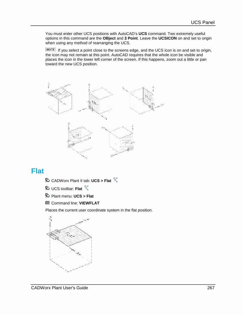
UCS Panel You must enter other UCS positions with AutoCAD’s UCS command. Two extremely useful options in this command are the OBject and 3 Point. Leave the UCSICON on and set to origin when using any method of rearranging the UCS.
If you select a point close to the screens edge, and the UCS icon is on and set to origin, the icon may not remain at this point. AutoCAD requires that the whole icon be visible and places the icon in the lower left corner of the screen. If this happens, zoom out a little or pan toward the new UCS position.
Flat CADWorx Plant II tab: UCS > Flat
UCS toolbar: Flat
Plant menu: UCS > Flat
Command line: VIEWFLAT
Places the current user coordinate system in the flat position.
CADWorx Plant User's Guide 267

UCS Panel
UCS Next UCS toolbar: Next
Plant menu: UCS > UCS Next
Command line: UCSNEXT
Toggles through each of the Point and Shoot UCS positions.
Compass UCS toolbar: Compass
UCS toolbar: Compass
Command line: COMPASS
Displays a compass-type symbol that indicates the Point and Shoot orientation. The symbol displays at the point you select.
As the display's orientation changes, the symbol changes accordingly.
The aliases VF, VN, VS, VE, and VW are also available.
North CADWorx Plant II tab: UCS > North
UCS toolbar: North
Plant menu: UCS > North
Command line: VIEWNORTH
Places the current user coordinate system in the north position.
268 CADWorx Plant User's Guide

UCS Panel
South CADWorx Plant II tab: UCS > South
UCS toolbar: South
Plant menu: UCS > South
Command line: VIEWSOUTH
Places the current user coordinate system in the south position.
West CADWorx Plant II tab: UCS > West
UCS toolbar: West
Plant menu: UCS > West
Command line: VIEWWEST
Places the current user coordinate system in the west position.
CADWorx Plant User's Guide 269

UCS Panel
East CADWorx Plant II tab: UCS > East
UCS toolbar: East
Plant menu: UCS > East
Command line: VIEWEAST
Places the current user coordinate system in the east position.
UCS Object UCS toolbar: UCS Object
Plant menu: UCS > UCS Object
Command line: UCS
Orients the UCS according to an object that you select. Please refer to the AutoCAD documentation on the UCS (User Coordinate System) for more detail.
This command is useful for rearranging dimensions in the model space (MSPACE) of a CADWorx isometric model. Run this command, and then select the dimension. The software places the UCS according to the position of the dimension allowing it to be stretched and moved.
270 CADWorx Plant User's Guide

S E C T I O N 1 7
CADWorx Steel / HVAC > Steel Shapes
Shape Name Command Line
Wide Flange WSHAPE
Channel CSHAPE
Angle LSHAPE
Tee TSHAPE
Pipe PSHAPE
Tube TSSHAPE
Flat Bar FBSHAPE
Round Bar RBSHAPE
Channel with Lip CLIPSHAPE
Angle with Lip LLIPSHAPE
Z ZSHAPE
Double Angle 2LSHAPE
Shapes CADWorx Steel / HVAC tab > Steel Shapes panel
Plant > Steel > Shapes
Command line: STEEL
Draws many different steel shapes in the drawing. When placing steel shapes, you can:
attach steel shapes to lines or you can specify the end points. place members into the current UCS. define the location of the centerline and the angle about the centerline. place steel on arcs. copy, stretch, or edit the size with the edit function.
Steel Shapes Panel
CADWorx Plant User's Guide 271
Steel Shapes Panel Draw Steel Dialog Box Select Type - Select the shape to place. The drop down lists each folder defined by the SteelLibraryDirectory (on page 43) startup variable. In each folder is a Type.ini file specifying the member type in that folder (W, T, TS, and so forth).
Select Data File - Select the data file that contains the component to place. All the data files located in the folder defined by the SteelLibraryDirectory (on page 43) startup variable display for selection. You can have a mix of metric and imperial data files in the same folder. CADWorx automatically converts the selected data file to the proper drawing units.
Select Member - Specifies the member to use. The delivered data files have members in alphabetical order. You can edit the data files to have the members in any order.
Rotation Angle - Select the component rotation about the centerline. You can select 0, 90, 180, 270, or type the needed rotation angle. Do not use AutoCAD commands (ROTATE, MIRROR, 3DROTATE) to change the rotation angle of the shape. The rotation angle of the shape can only be set from the Draw Steel dialog box.
Pick Insertion Location - Click to select the insertion point. The red box indicates the active location.
Centerline location - Select the top, center, or bottom location of the centerline relative to the component shape. The centerline location can only be along the three locations on the Y-axis of the component.
Use UCS - Select to use the current UCS as the XY plane. For example, if the UCS is located in the same plane as a slope roof, components are easily added at this angle if you select this option. Select two points within the plane to determine the rotation automatically.
Existing - Edits the existing status of the plate.
Short Annotation - Defines the short annotation name for the component. The default value is the text in the MEMBER column of the data file up to the first "X" character.
Long Annotation - Defines the long annotation name for the component. The default value is the text in the MEMBER column of the data file.
Description - Defines the component description. The default value is the "DESCRIPTION=" value in the data file header.
Part Number - Specifies the part number for the component. You can enter the part number yourself or use the part number automatically assigned by the SteelPartNumberFile (on page 44) startup variable.
Material - Specifies the material for the component. The default value is the "MATERIAL=" value in the data file header.
Pick Points - Click to define the component by two points on the screen.
Select Lines - Click to select lines in the drawing to place the component. The length and position of the line define the component.
Properties - Activates the Properties dialog box that you can use to edit the shape properties before placement. For more information, see Properties Dialog Box.
User Input - Activates the User Input dialog box that you can use to create a custom-dimensioned shape. Select a shape that is close to the size you need before clicking User Input. For more information, see User Input Dialog Box.
272 CADWorx Plant User's Guide

Steel Shapes Panel Properties Dialog Box Displays the available properties of the selected member.
The reference data file path and file name is shown at the top.
Weight - Displays the weight of the component. Select Manual Update to enter the weight yourself.
Length - Displays the length of the component. Select Manual Update to enter the length yourself. The component length is calculated based on the shape of the solid, not the length of the centerline. For example, if one end of the component is cut 45 degrees, the full length would be to the very end of the 45 degree cut, not the centerline length.
The top grid displays the required properties to place the shape. Do not add to or edit the order of these properties in the data file or the component does not place correctly in the drawing.
The bottom grid displays the optional properties. You can add or remove properties in the data file as needed. For example, you might want to add a column in the data file for the gage distance.
User Input Dialog Box Defines custom dimensioned components.
Dimensions - Displays the dimensions that you can define. Refer to the figure for a key of which dimension is which.
Rotation Angle - Select the component rotation about the centerline or base point. You can select 0, 90, 180, 270, or type the needed rotation angle.
Short Annotation - Defines the short annotation name for the component.
Long Annotation - Defines the long annotation name for the component. The thickness, length, and width dimensions are appended to the long annotation as the component is drawn and placed.
Description - Defines the component description.
Density - Defines the material density for the component.
Use the SteelLibraryDirectory (on page 43) startup variable to define the data files location associated with the steel software. The delivered libraries are Steel_I and Steel_M. Steel_I contains imperial unit data files using inches while Steel_M contains metric data files. At the top of each data file is an entry that defines the type of data file: metric or imperial. The software reads this entry in the data file and determines if the units need to be converted. For example, when SystemMeasure (on page 45) is set to 2 (metric system with nominal inch input) and you want to use an imperial data file from Steel_I, the system automatically converts the data file values from inches into millimeters. Select the data file to use using the SteelLibraryDirectory variable.
Steel channel and angle shapes cannot be modified using the AutoCAD MIRROR command. Use Flip Flange in the dialog to mirror channel and angle shapes.
CADWorx Plant User's Guide 273

Steel Shapes Panel When editing shape data files, remember these rules:
Columns have to be separated by two or more spaces.
First column has to be called "MEMBER". The member name cannot have two consecutive spaces.
Required columns have to in the exact order listed for each type of steel shape to generate the AutoCAD solid.
All columns after the required columns are optional. These optional columns display in the Properties dialog box for reference. The Ix (Inertia about X-axis), Iy (Inertia about Y-axis), and J (torsion) columns might be used by the SEXPORT command when export to CAESAR II Steel (*.str) files.
The cross sectional area (AREA) and fillet radius (R) columns are required in the data file but are not used by the software to generate the AutoCAD solid shape. These values are not stored with the component.
For imperial sizes:
Weight (WGT) column is in pounds per foot (lbs/ft)
Area (AREA) column is in square inches (in2)
All other required columns are in inches (in)
For metric sizes:
Weight (WGT) column is in kilograms per meter (kg/m)
Area (AREA) column is in square centimeters (cm2)
All other required columns are in millimeters (mm)
Wide Flange Shapes Data file sample (TYPE=W)
274 CADWorx Plant User's Guide
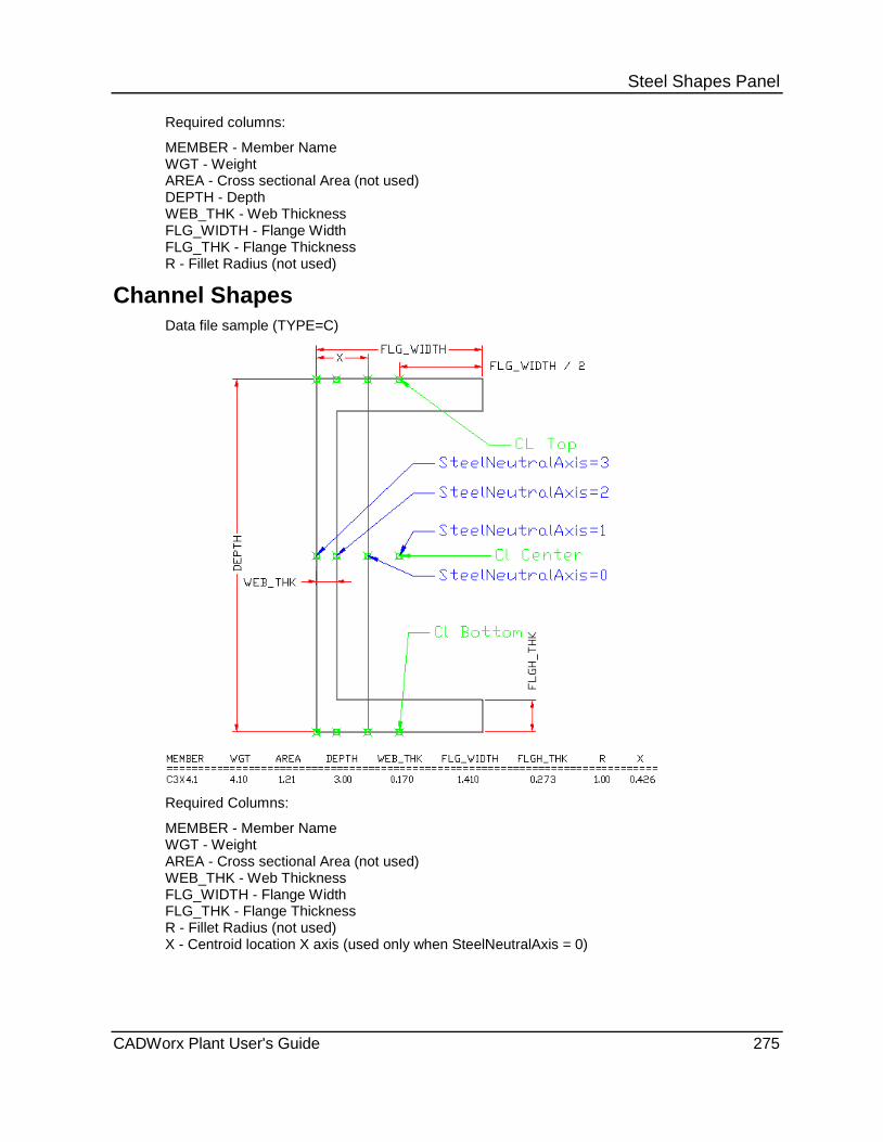
Steel Shapes Panel Required columns:
MEMBER - Member Name WGT - Weight AREA - Cross sectional Area (not used) DEPTH - Depth WEB_THK - Web Thickness FLG_WIDTH - Flange Width FLG_THK - Flange Thickness R - Fillet Radius (not used)
Channel Shapes Data file sample (TYPE=C)
Required Columns:
MEMBER - Member Name WGT - Weight AREA - Cross sectional Area (not used) WEB_THK - Web Thickness FLG_WIDTH - Flange Width FLG_THK - Flange Thickness R - Fillet Radius (not used) X - Centroid location X axis (used only when SteelNeutralAxis = 0)
CADWorx Plant User's Guide 275
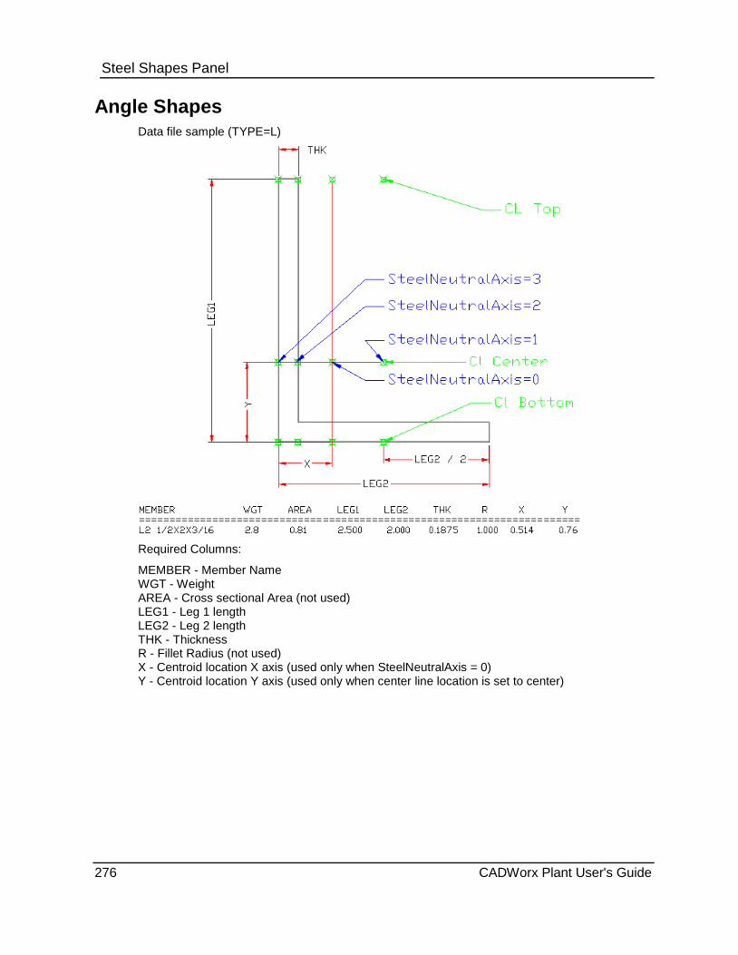
Steel Shapes Panel
Angle Shapes Data file sample (TYPE=L)
Required Columns:
MEMBER - Member Name WGT - Weight AREA - Cross sectional Area (not used) LEG1 - Leg 1 length LEG2 - Leg 2 length THK - Thickness R - Fillet Radius (not used) X - Centroid location X axis (used only when SteelNeutralAxis = 0) Y - Centroid location Y axis (used only when center line location is set to center)
276 CADWorx Plant User's Guide

Steel Shapes Panel
Tee Shapes Data file sample (TYPE=WT)
Required Columns:
MEMBER - Member Name WGT - Weight AREA - Cross sectional Area (not used) DEPTH - Depth STEM_THK - Stem Thickness FLG_WIDTH - Flange Width FLG_THK - Flange Thickness R - Fillet Radius (not used) Y - Centroid location Y axis (used only when center line location is set to center)
CADWorx Plant User's Guide 277
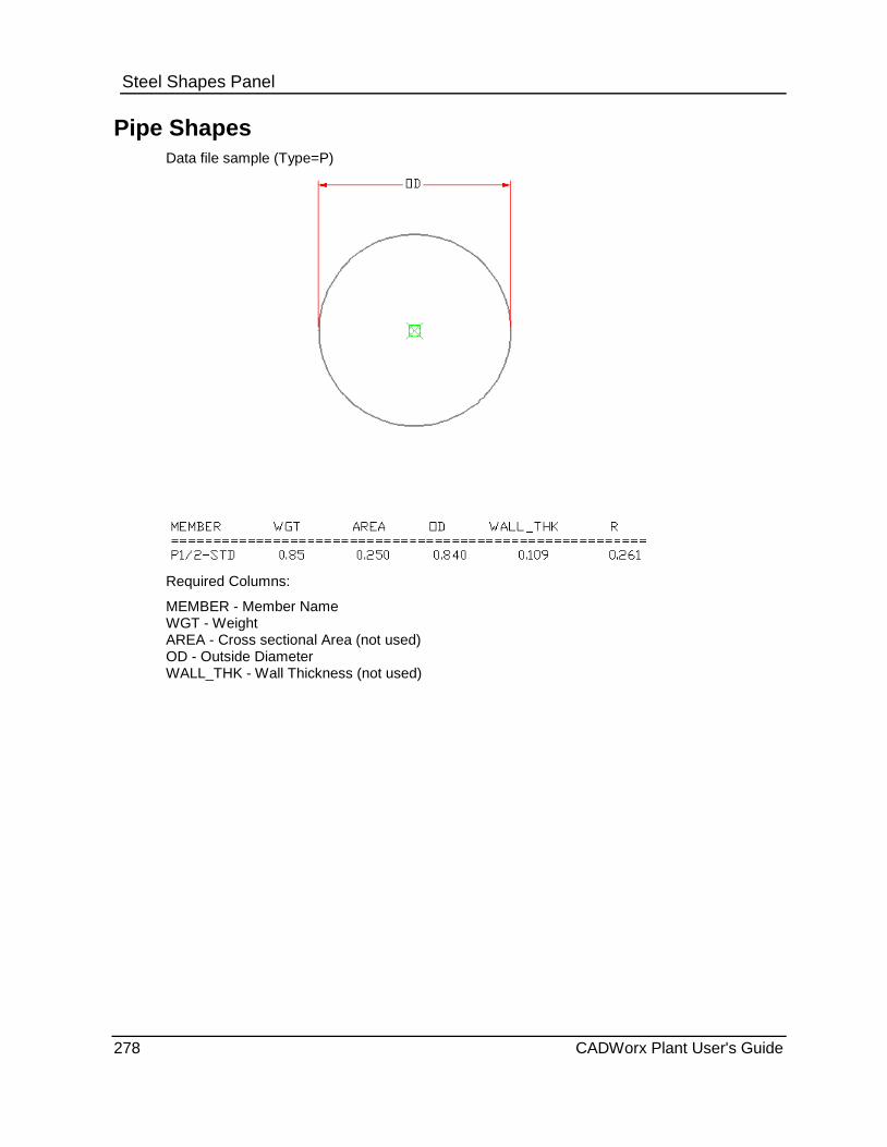
Steel Shapes Panel
Pipe Shapes Data file sample (Type=P)
Required Columns:
MEMBER - Member Name WGT - Weight AREA - Cross sectional Area (not used) OD - Outside Diameter WALL_THK - Wall Thickness (not used)
278 CADWorx Plant User's Guide

Steel Shapes Panel
Tube Shapes Data file sample (Type=TS)
Required Columns:
MEMBER - Member Name WGT - Weight AREA - Cross sectional Area (not used) SIDE1 - Side 1 length SIDE2 - Side 2 length THK - Thickness R - Fillet Radius (not used)
CADWorx Plant User's Guide 279

Steel Shapes Panel
Flat Bar Shapes Data file sample (TYPE=FB)
Required Columns:
MEMBER - Member Name WGT - Weight AREA - Cross sectional Area (not used) WIDTH - Width THK - Thickness
280 CADWorx Plant User's Guide
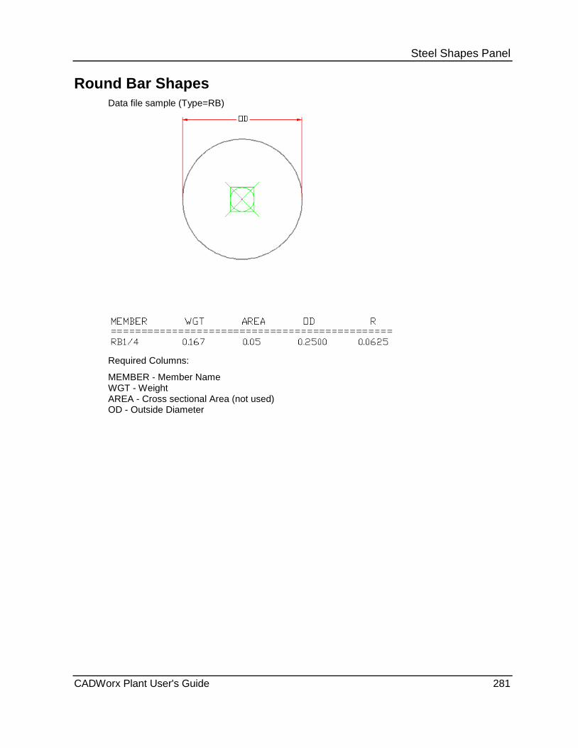
Steel Shapes Panel
Round Bar Shapes Data file sample (Type=RB)
Required Columns:
MEMBER - Member Name WGT - Weight AREA - Cross sectional Area (not used) OD - Outside Diameter
CADWorx Plant User's Guide 281

Steel Shapes Panel
Channel Shape with Lip Data file sample (TYPE=C_LIP):
Required Columns:
MEMBER - Member Name WGT - Weight AREA - Cross sectional Area (not used) DEPTH - Web Thickness THK - Thickness FLG_WIDTH - Flange Width LIP - Lip Length X - Centroid location X axis (used only when SteelNeutralAxis = 0)
282 CADWorx Plant User's Guide

Steel Shapes Panel
Angle Shape with Lip Data file sample (TYPE=L_LIP):
Required Columns:
MEMBER - Member Name WGT - Weight AREA - Cross sectional Area (not used) LEG1 - Leg 1 length THK - Thickness LEG2 - Leg 2 length LIP - Lip Length X - Centroid location X axis (used only when SteelNeutralAxis = 0) Y - Centroid location Y axis (used only when center line location is set to center)
CADWorx Plant User's Guide 283

Steel Shapes Panel
Z Shapes Data file sample (TYPE=Z):
Columns:
MEMBER - Member Name WEIGHT - Weight AREA - Cross sectional Area (not used) HEIGHT - Height THK - Thickness LEG1 - Leg 1 length LIP1 - Lip 1 length (optional) LEG2 - Leg 2 length (optional) LIP2 - Lip 2 length (optional) THK_LEG1 - Leg 1 thickness (optional) THK_LEG2 - Lip 1 thickness (optional) THK_LIP1 - Leg 2 thickness (optional) THK_LIP2 - Lip 2 thickness (optional)
284 CADWorx Plant User's Guide
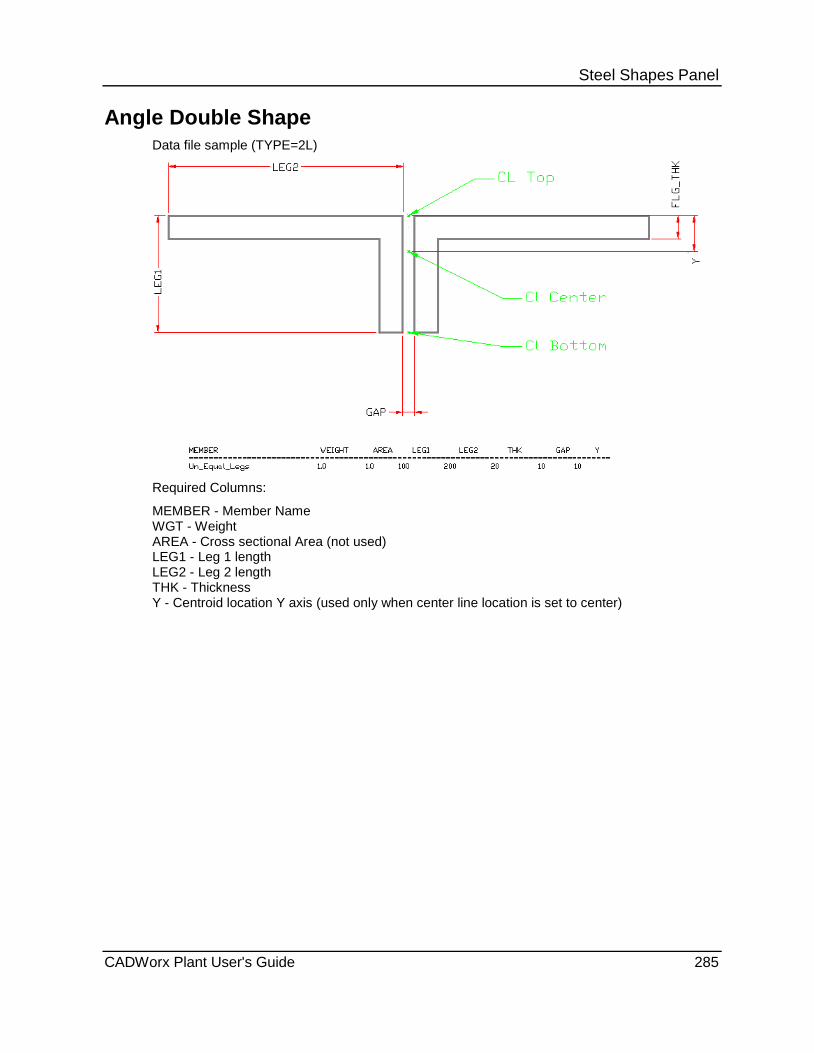
Steel Shapes Panel
Angle Double Shape Data file sample (TYPE=2L)
Required Columns:
MEMBER - Member Name WGT - Weight AREA - Cross sectional Area (not used) LEG1 - Leg 1 length LEG2 - Leg 2 length THK - Thickness Y - Centroid location Y axis (used only when center line location is set to center)
CADWorx Plant User's Guide 285

Steel Shapes Panel
286 CADWorx Plant User's Guide
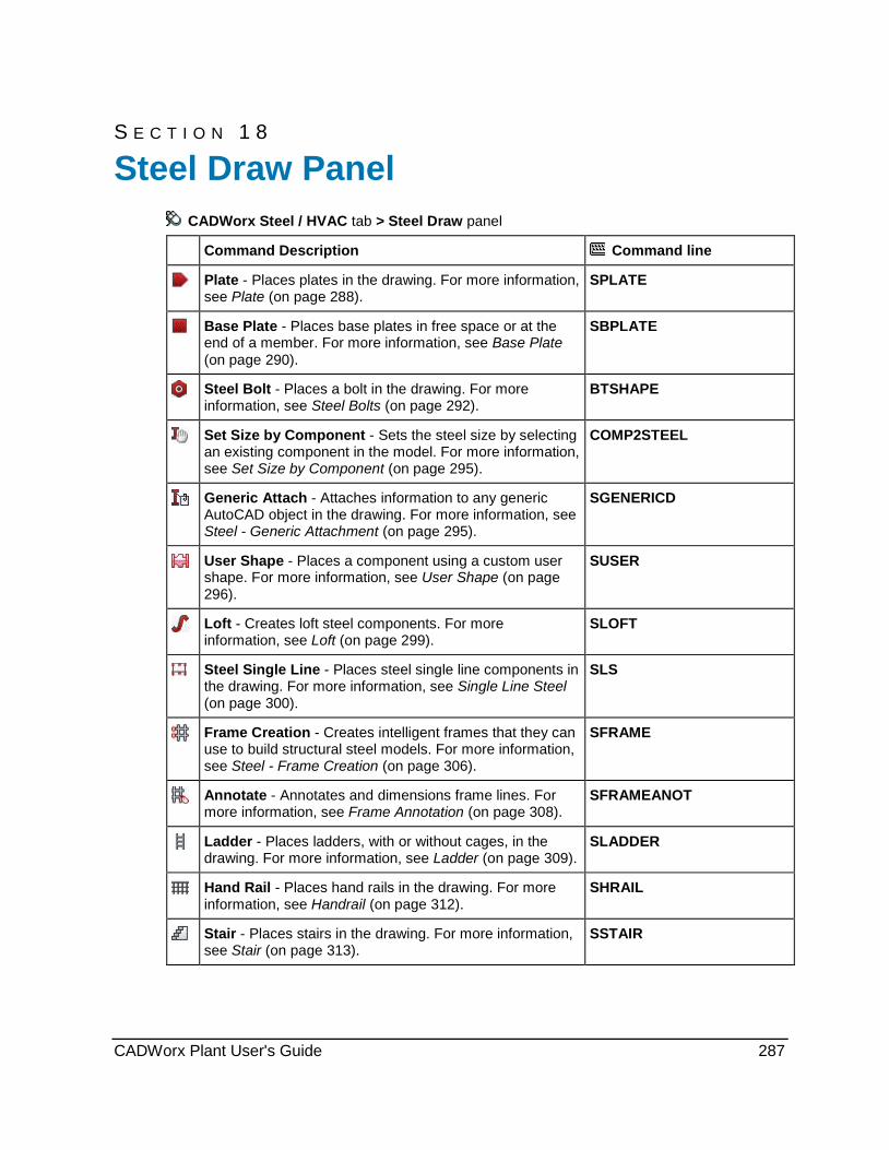
S E C T I O N 1 8
CADWorx Steel / HVAC tab > Steel Draw panel
Command Description Command line
Plate - Places plates in the drawing. For more information, see Plate (on page 288).
SPLATE
Base Plate - Places base plates in free space or at the end of a member. For more information, see Base Plate (on page 290).
SBPLATE
Steel Bolt - Places a bolt in the drawing. For more information, see Steel Bolts (on page 292).
BTSHAPE
Set Size by Component - Sets the steel size by selecting an existing component in the model. For more information, see Set Size by Component (on page 295).
COMP2STEEL
Generic Attach - Attaches information to any generic AutoCAD object in the drawing. For more information, see Steel - Generic Attachment (on page 295).
SGENERICD
User Shape - Places a component using a custom user shape. For more information, see User Shape (on page 296).
SUSER
Loft - Creates loft steel components. For more information, see Loft (on page 299).
SLOFT
Steel Single Line - Places steel single line components in the drawing. For more information, see Single Line Steel (on page 300).
SLS
Frame Creation - Creates intelligent frames that they can use to build structural steel models. For more information, see Steel - Frame Creation (on page 306).
SFRAME
Annotate - Annotates and dimensions frame lines. For more information, see Frame Annotation (on page 308).
SFRAMEANOT
Ladder - Places ladders, with or without cages, in the drawing. For more information, see Ladder (on page 309).
SLADDER
Hand Rail - Places hand rails in the drawing. For more information, see Handrail (on page 312).
SHRAIL
Stair - Places stairs in the drawing. For more information, see Stair (on page 313).
SSTAIR
Steel Draw Panel
CADWorx Plant User's Guide 287
Steel Draw Panel
Plate CADWorx Steel / HVAC tab: Steel Draw > Plate
Steel toolbar: Plate
Plant menu: Steel > Plate
Command line: SPLATE
Creates plates in the model using existing shapes or by specifying a minimum of three plate corners. You define the extrusion direction after selecting the shape or defining the corners.
Use the SteelLibraryDirectory (on page 43) startup variable to define plate data files location. The delivered libraries are Steel_I and Steel_M. Steel_I contains imperial unit data files using inches while Steel_M contains metric data files. At the top of each data file is an entry that defines the type of data file: metric or imperial. The software reads this entry in the data file and determines if the units need to be converted. For example, when SystemMeasure (on page 45) is set to 2 (metric system with nominal inch input) and you want to use an imperial data file from Steel_I, the system automatically converts the data file values from inches into millimeters. Select the data file to use using the SteelLibraryDirectory variable.
Draw Plate Dialog Box Select Data File - Select the data file that contains the component to place. All the data files located in the folder defined by the SteelLibraryDirectory (on page 43) startup variable display for selection. You can have a mix of metric and imperial data files in the same folder. CADWorx automatically converts the selected data file to the proper drawing units.
Select Member - Specifies the member to use. The delivered data files have members in alphabetical order. You can edit the data files to have the members in any order.
Existing - Edits the existing status of the plate.
Short Annotation - Defines the short annotation name for the plate. The default value is the text in the MEMBER column of the data file up to the first "X" character.
Long Annotation - Defines the long annotation name for the plate. The default value is the text in the MEMBER column of the data file.
Description - Defines the plate description. The default value is the "DESCRIPTION=" value in the data file header.
Part Member - Specifies the part number for the plate. You can enter the part number yourself or use the part number automatically assigned by the SteelPartNumberFile (on page 44) startup variable.
Material - Specifies the material for the plate. The default value is the "MATERIAL=" value in the data file header.
Length - Displays the length of the plate computed by finding a bounding box around the plate aligned along an alignment axis. The alignment axis through the plate is the axis formed by the long segment of the polyline used to create the plate.
Width - Displays the width of the plate computed by finding a bounding box around the plate aligned along an alignment axis. The alignment axis through the plate is the axis formed by the long segment of the polyline used to create the plate.
Weight - Displays the weight of the plate. Select Manual Update to enter the value yourself.
288 CADWorx Plant User's Guide

Steel Draw Panel Manual Update - Select this option to manually specify the plate weight in the Weight box. Clear this option to have the software compute the plate weight using the shape and the weight defined in the data file.
Insert Location - Select the centerline location for the plate. This option is only available when editing an existing plate in the model.
Pick Points - Click to define the plates by its corners.
Select Lines - Click to define the plate using an existing closed polyline shape.
Select Curves - Click to define the plate using an existing closed curved shape.
What do you want to do? Place plate by points (on page 289)
Place plate by closed polyline (on page 289)
Place plate by curves (on page 290)
Place plate by points 1. On the Steel Draw panel, click Plate .
You can also type SPLATE in the command line.
The Draw Plate dialog box displays.
2. In the Select Data File box, select Structural Plate.
3. Select the plate to place in the Select Member list.
4. Edit the Details boxes as needed.
5. Click Pick points.
6. Define the first corner location of the plate.
7. Continue to define the corners of the plate. When you are finished, right-click and then select Enter on the menu.
8. Select Positive or Negative from the context menu. You can also press ENTER for positive Z direction or press N for negative.
Place plate by closed polyline 1. On the Steel Draw panel, click Plate .
You can also type SPLATE in the command line. The Draw Plate dialog box displays.
2. In the Select Data File box, select Structural Plate. 3. Select the plate to place in the Select Member list. 4. Edit the Details boxes as needed. 5. Click Select line(s). 6. Select an existing closed polyline shape in the model. 7. Right-click and, then select Positive or Negative from the context menu.
You can also press ENTER for positive Z direction or press N for negative.
CADWorx Plant User's Guide 289

Steel Draw Panel
Place plate by curves 1. On the Steel Draw panel, click Plate .
You can also type SPLATE in the command line.
The Draw Plate dialog box displays.
2. In the Select Data File box, select Structural Plate.
3. Select the plate to place in the Select Member list.
4. Edit the Details boxes as needed.
5. Click Select curve(s).
6. Select the existing curves in the model.
7. Right-click.
8. Enter the width distance for the plate.
9. Click in the model to indicate which direction to apply the width.
10. Select Bottom, Center, or Top for the insertion location.
Base Plate CADWorx Steel / HVAC tab: Steel Draw > Base Plate
Steel toolbar: Base Plate
Plant menu: Steel > Base Plate
Command line: SBPLATE
Places base plates in open space or attached to the end of a steel member. CADWorx automatically copes the steel member with the base plate.
Base Plate Dialog Box Select Data File - Select the data file that contains the component to place. All the data files located in the folder defined by the SteelLibraryDirectory (on page 43) startup variable display for selection. You can have a mix of metric and imperial data files in the same folder. CADWorx automatically converts the selected data file to the proper drawing units.
Select Member - Specifies the member to use. The delivered data files have members in alphabetical order. You can edit the data files to have the members in any order.
Details Existing - Edits the existing status of the plate.
Short annotation - Defines the short annotation name for the plate. The default value is the text in the MEMBER column of the data file up to the first "X" character.
Long annotation - Defines the long annotation name for the plate. The default value is the text in the MEMBER column of the data file.
Description - Defines the plate description. The default value is the "DESCRIPTION=" value in the data file header.
290 CADWorx Plant User's Guide
Steel Draw Panel Part number - Specifies the part number for the plate. You can enter the part number yourself or use the part number automatically assigned by the SteelPartNumberFile (on page 44) startup variable.
Material - Specifies the material for the plate. The default value is the "MATERIAL=" value in the data file header.
Weight - Displays the weight of the plate. The software automatically subtracts the material weight removed by any holes from the plate weight. Select Manual Update to enter the value yourself.
Manual Update - Select this option to manually specify the plate weight in the Weight box. Clear this option to have the software compute the plate weight using the shape and the weight defined in the data file.
Plate Dimensions Length - Displays the length of the plate computed by finding a bounding box around the plate aligned along an alignment axis. The alignment axis through the plate is the axis formed by the long segment of the polyline used to create the plate. Width - Displays the width of the plate computed by finding a bounding box around the plate aligned along an alignment axis. The alignment axis through the plate is the axis formed by the long segment of the polyline used to create the plate. Rotation - Specifies the rotation angle for the plate placement. X offset - Specifies the X-axis offset from the plate centroid. Y offset - Specifies the Y-axis offset from the plate centroid.
Hole Dimensions On/Off - Select this option to place holes in the base plate. Clear this option to place a plate without holes. Row count - Enter the number of hole rows. Row spacing - Enter the distance between the hole rows measured from the center of the holes. Column count - Enter the number of hole columns. Column spacing - Enter the distance between the hole columns measured from the center of the holes. Diameter - Enter the diameter of the hole. Rotation - Enter the angle at which to rotate the hole rows and columns within the base plate. Slotted length - Enter a distance to create an elongated hole. This distance is measured from the hole center. X offset - Specifies the X-axis offset for the holes. Holes places at zero offset are at the base plate center. Y offset - Specifies the Y-axis offset for the holes. Holes places at zero offset are at the base plate center. Pick Point - Click to place the base plate.
What do you want to do? Place a base plate (on page 292)
Place a base plate with holes (on page 292)
CADWorx Plant User's Guide 291

Steel Draw Panel
Place a base plate 1. On the Steel Draw panel, click Base Plate .
You can also type SBPLATE in the command line.
The Steel Base Plates dialog box displays.
2. In the Select Data File box, select Structural Plate.
3. Select the plate to place in the Select Member list.
4. Edit the Details boxes as needed.
5. Edit the Plate dimensions boxes as needed.
6. Clear the On/Off option to place the base plate without holes.
7. Click Pick point.
The prompt Specify center base point displays.
8. Define the location for the base plate center.
9. Continue to define the locations for addition base plates as needed.
Place a base plate with holes 1. On the Steel Draw panel, click Base Plate .
You can also type SBPLATE in the command line.
The Steel Base Plates dialog box displays.
2. In the Select Data File box, select Structural Plate.
3. Select the plate to place in the Select Member list.
4. Edit the Details boxes as needed.
5. Edit the Plate dimensions boxes as needed.
6. Select the On/Off option to place the base plate with holes.
7. Enter the values for the hole dimensions and locations.
8. Click Pick point.
The prompt Specify center base point displays.
9. Define the location for the base plate center.
10. Continue to define the locations for addition base plates as needed.
Steel Bolts CADWorx Steel / HVAC tab: Steel Draw > Steel Bolts
Command line: BTSHAPE
Draws bolts in the drawing. You can place bolt shapes on lines, or you can specify the end points.
292 CADWorx Plant User's Guide
Steel Draw Panel Draw Steel Dialog Box Select Type - Select the shape to place. The drop down lists each folder defined by the SteelLibraryDirectory (on page 43) startup variable. In each folder is a Type.ini file specifying the member type in that folder (W, T, TS, and so forth).
Select Data File - Select the data file that contains the component to place. All the data files located in the folder defined by the SteelLibraryDirectory (on page 43) startup variable display for selection. You can have a mix of metric and imperial data files in the same folder. CADWorx automatically converts the selected data file to the proper drawing units.
Select Member - Specifies the member to use. The delivered data files have members in alphabetical order. You can edit the data files to have the members in any order.
Rotation Angle - Select the component rotation about the centerline. You can select 0, 90, 180, 270, or type the needed rotation angle. Do not use AutoCAD commands (ROTATE, MIRROR, 3DROTATE) to change the rotation angle of the shape. The rotation angle of the shape can only be set from the Draw Steel dialog box.
Pick Insertion Location - Click to select the insertion point. The red box indicates the active location.
Centerline location - Select the top, center, or bottom location of the centerline relative to the component shape. The centerline location can only be along the three locations on the Y-axis of the component.
Use UCS - Select to use the current UCS as the XY plane. For example, if the UCS is located in the same plane as a slope roof, components are easily added at this angle if you select this option. Select two points within the plane to determine the rotation automatically.
Existing - Edits the existing status of the plate.
Short Annotation - Defines the short annotation name for the component. The default value is the text in the MEMBER column of the data file up to the first "X" character.
Long Annotation - Defines the long annotation name for the component. The default value is the text in the MEMBER column of the data file.
Description - Defines the component description. The default value is the "DESCRIPTION=" value in the data file header.
Part Number - Specifies the part number for the component. You can enter the part number yourself or use the part number automatically assigned by the SteelPartNumberFile (on page 44) startup variable.
Material - Specifies the material for the component. The default value is the "MATERIAL=" value in the data file header.
Pick Points - Click to define the component by two points on the screen.
Select Lines - Click to select lines in the drawing to place the component. The length and position of the line define the component.
Properties - Activates the Properties dialog box that you can use to edit the shape properties before placement. For more information, see Properties Dialog Box.
User Input - Activates the User Input dialog box that you can use to create a custom-dimensioned shape. Select a shape that is close to the size you need before clicking User Input. For more information, see User Input Dialog Box.
CADWorx Plant User's Guide 293

Steel Draw Panel Properties Dialog Box Displays the available properties of the selected member.
The reference data file path and file name is shown at the top.
Weight - Displays the weight of the component. Select Manual Update to enter the weight yourself.
Length - Displays the length of the component. Select Manual Update to enter the length yourself. The component length is calculated based on the shape of the solid, not the length of the centerline. For example, if one end of the component is cut 45 degrees, the full length would be to the very end of the 45 degree cut, not the centerline length.
The top grid displays the required properties to place the shape. Do not add to or edit the order of these properties in the data file or the component does not place correctly in the drawing.
The bottom grid displays the optional properties. You can add or remove properties in the data file as needed. For example, you might want to add a column in the data file for the gage distance.
User Input Dialog Box Defines custom dimensioned components.
Dimensions - Displays the dimensions that you can define. Refer to the figure for a key of which dimension is which.
Rotation Angle - Select the component rotation about the centerline or base point. You can select 0, 90, 180, 270, or type the needed rotation angle.
Short Annotation - Defines the short annotation name for the component.
Long Annotation - Defines the long annotation name for the component. The thickness, length, and width dimensions are appended to the long annotation as the component is drawn and placed.
Description - Defines the component description.
Density - Defines the material density for the component.
Use the SteelLibraryDirectory (on page 43) startup variable to define the data files location associated with the steel software. The delivered libraries are Steel_I and Steel_M. Steel_I contains imperial unit data files using inches while Steel_M contains metric data files. At the top of each data file is an entry that defines the type of data file: metric or imperial. The software reads this entry in the data file and determines if the units need to be converted. For example, when SystemMeasure (on page 45) is set to 2 (metric system with nominal inch input) and you want to use an imperial data file from Steel_I, the system automatically converts the data file values from inches into millimeters. Select the data file to use using the SteelLibraryDirectory variable.
294 CADWorx Plant User's Guide

Steel Draw Panel
Set Size by Component CADWorx Steel / HVAC tab: Steel Draw > Set Size by Component
Steel toolbar: Set Size by Component
Plant menu: Steel > Utility > Size by Component
Command line: COMP2STEEL
Sets the steel size by selecting an existing component in the model.
1. On the Steel Draw panel, click Set Size by Component .
2. Select an existing component in the model that has the size that you want to use.
Steel - Generic Attachment CADWorx Steel / HVAC tab: Steel Draw > Generic Attach
Command line: SGENERICD
Attaches information to any generic AutoCAD object in the drawing. You can use the information later in bill of material extraction, labeling, and so forth. After manually constructing a component, use this routine to attach xdata information.
You cannot attach information to a CADWorx object or component.
To pinpoint the center of gravity locations use the Osnap commands. For example, to place information on a beam and have it reflect the CG correctly, draw a centerline and pick MIDpoint or NEArest to the end of the centerline or the exact known location.
Generic Attach (Create/Edit) Dialog Box Controls parameters for attaching information to generic AutoCAD objects.
Long Annotation - Specifies the long annotation for the component, such as W6X25.
Description - Specifies the description for the component, such as Wide Flange.
Short Annotation - Specifies the short annotation for the component, such as W6.
Part number - Specifies the part number for the component, such as 12345.
Material - Specifies the material for the component, such as ASTM A-36.
Length - Specifies the length of the component. Any real number is valid.
Weight - Specifies the weight of the component. Any real number is valid.
BOM Mark Point - Shows the drawing coordinate location at which the information was attached.
Specify On-screen - Click the location in the model view to specify the bill of material mark point.
X - Specifies the X-location for the bill of material mark point. This value defaults to zero.
Y - Specifies the Y-location for the bill of material mark point. This value defaults to zero.
Z - Specifies the Z-location for the bill of material mark point. This value defaults to zero.
CADWorx Plant User's Guide 295

Steel Draw Panel CG Location - Shows the center of gravity location at which the information was attached.
Specify On-screen - Click the location in the model view to specify the generic attach center of gravity point.
X - Specifies the X-location for the generic attach center of gravity location. This value defaults to zero.
Y - Specifies the Y-location for the generic attach center of gravity location. This value defaults to zero.
Z - Specifies the Z-location for the generic attach center of gravity location. This value defaults to zero.
1. On the Steel Draw panel, click Generic Attach .
You can also type SGENERICD in the command line.
The Generic Attach (Create) dialog box displays.
2. Enter the information to attach in the appropriate boxes.
3. Click Attach.
4. Select the non CADWorx object to attach the information.
5. Press ENTER to finish.
After the information is attached you can use the Specify On-screen options for BOM Mark Point and COG Location to indicate those points on the object. These options help to determine the Center of Gravity.
Specify the Bill of Material Mark Point and the Center of Gravity Location 1. Double-click the entity.
The Generic Attach (Edit) dialog box displays.
2. Click Specify On-screen under BOM Mark Point.
3. Select a point on the object to specify the mark point.
A red arrow displays indicating the point.
4. Click Specify On-screen under CG Location.
5. Select a point on the object to specify the mark point.
A green arrow displays indicating the location.
6. Click OK.
User Shape CADWorx Steel / HVAC tab: Steel Draw > User Shape Plant menu: Steel > User Shape Command line: SUSER
Places a component using a custom user shape. You select the component to draw based on the user shape DWG file that you previously created. The extrusion direction and distance is based on points picked or line selected in the drawing. You can edit Roll angle along with the standard annotations.
296 CADWorx Plant User's Guide

Steel Draw Panel User Shapes Dialog Box Controls parameters for placing user-defined shapes in the drawing.
Short Annotation - Specifies the short annotation for the shape. The default value comes from the drawing file that contains the user shape.
Long Annotation - Specifies the long annotation description for the shape. The default value comes from the drawing file that contains the user shape.
Description - Specifies the description for the shape. The default value comes from the drawing file that contains the user shape.
Part Number - Specifies the part number for the shape. The default value comes from the drawing file that contains the user shape.
Material - Specifies the material for the shape. The default value comes from the drawing file that contains the user shape.
Length - Specifies the length of the shape.
Weight - Specifies the weight of the shape.
Roll Angle - Specifies the roll angle about the placement line for the shape. Do not use AutoCAD commands (ROTATE, MIRROR, 3DROTATE) to change the roll angle of the shape. The roll angle of the shape can only be set from the User Shapes dialog box.
Pick points - Places the shape between two points that you identify in the drawing.
Select line - Places the square straight or oval straight shape along an existing polyline in the drawing. This option is disabled for all other shapes.
For user shapes to work, an ASCII file named Type.ini must be in the same folder as the user shape drawing files. The Type.ini must have TYPE=USER as the first line in the file. The folder ..\CADWorx (version)\Steel_I\User Shape is used to store the user shape drawing files.
The figure below shows the parameters stored in a user created DWG file that can be used to create a roof purlin user shape.
CADWorx Plant User's Guide 297

Steel Draw Panel After selecting the user shape from the dialog, you pick points or select a line to define the extrusion length. See the figure below.
1. On the Steel Draw panel, click User Shape .
You can also type SUSER in the command line.
The User Shapes dialog box displays.
2. In the Select Member box, select the user shape to use.
3. Enter values in the Details boxes as needed.
4. Click Pick points to place the component by defining the two end locations.
-or-
Click Select line to select an existing line in the drawing on which to place the component.
298 CADWorx Plant User's Guide
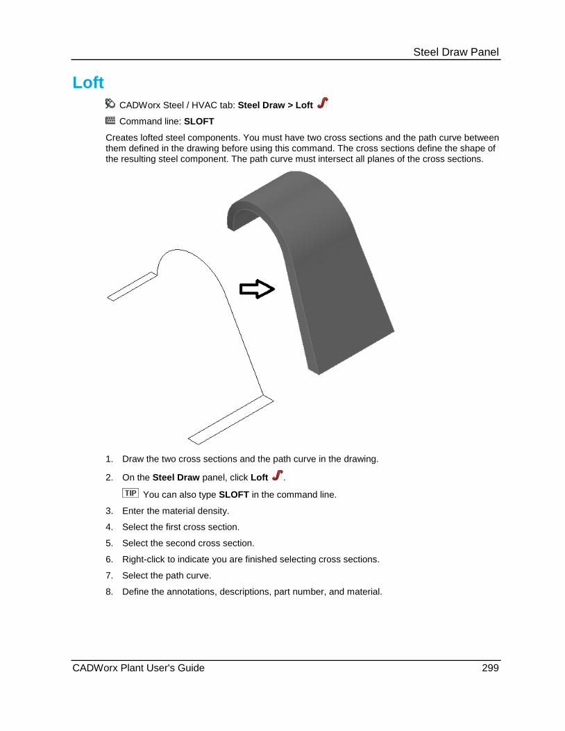
Steel Draw Panel
Loft CADWorx Steel / HVAC tab: Steel Draw > Loft
Command line: SLOFT
Creates lofted steel components. You must have two cross sections and the path curve between them defined in the drawing before using this command. The cross sections define the shape of the resulting steel component. The path curve must intersect all planes of the cross sections.
1. Draw the two cross sections and the path curve in the drawing.
2. On the Steel Draw panel, click Loft .
You can also type SLOFT in the command line.
3. Enter the material density.
4. Select the first cross section.
5. Select the second cross section.
6. Right-click to indicate you are finished selecting cross sections.
7. Select the path curve.
8. Define the annotations, descriptions, part number, and material.
CADWorx Plant User's Guide 299

Steel Draw Panel
Single Line Steel CADWorx Steel / HVAC tab: Steel Draw > Single Line Steel Command line: SLS
Using the Steel Single Line program 1. Generate the 3D model of the steel in Model Space. 2. Create viewports in the Layouts. 3. Configure the object settings on the General tab. (see below). 4. Generate the viewports. 5. Apply new settings to objects. 6. Configure the dimension settings on the Dimension tab (see below). 7. Dimension the viewport.
This feature is only part of CADWorx Steel Professional Plus or CADWorx Plant Professional. Using the Steel Drawing Manager The palette can be resized, docked and hidden like any AutoCAD palette. The command SLSSHOWPALETTE shows the palette if it is hidden. The column line between the field labels and the settings can be moved left or right to resize the columns.
General Tab
300 CADWorx Plant User's Guide

Steel Draw Panel Tools
Save Settings to File - Save your set of settings to an external file for use in another drawing
Load Settings From File - Load a saved set of settings from a file into the drawing. Any existing named settings are lost when a new set is loaded from the file.
Add Setting - Add a name to a set of settings you want to reuse.
Delete Setting - Delete a named setting from the list.
Match Settings - Apply settings from one object to other objects.
Turn off Vertical symbols - Used to turn off vertically places symbols representing Z-Axis objects.
Generate - Generate the steel member drawing objects in a viewport.
Set to Object - Apply new settings to a viewport or individual steel components already drawn.
Update - Updates the existing objects to match changes made to the model
Reset Settings - Resets individual member objects back to the viewport settings and link them back to the view port.
Archive drawings - Detaches all intelligence from the drawing objects. Underlying models can be removed.
Turn of Vertical Symbols - Used to turn on vertically places symbols representing Z-Axis objects previously turned off.
Settings List Box - Choose the named settings.
Line Settings
CADWorx Plant User's Guide 301

Steel Draw Panel Layer - AutoCAD Layer for New Steel. Color - AutoCAD object color for New Steel. Linetype - Loaded AutoCAD linetype for New Steel. Weight - AutoCAD line weight for New Steel. Layer Exist - AutoCAD Layer for Existing Steel. Color Exist - AutoCAD object color for Existing Steel. Weight Exist - AutoCAD line weight for Existing Steel. Gap Style - Used to set either Manual gap distance or automatic gap distance. Automatic uses the steel member end gap type to gap the lines set by the Gap Distance
setting. Manual applies the Gap Distance to all ends regardless of gap type. Gap Distance - This is a paper space distance for the coping gaps.
Tag Settings
Layer - AutoCAD Layers. Color - AutoCAD object colors. Text Style - Loaded text styles. Text Height - Paper space text height. Offset - Set an offset above the line / symbol for the tag to be placed. Justification - AutoCAD text justifications. Style - Short or Long descriptions. Display - Display of the tag, on or off.
Symbol Settings
302 CADWorx Plant User's Guide
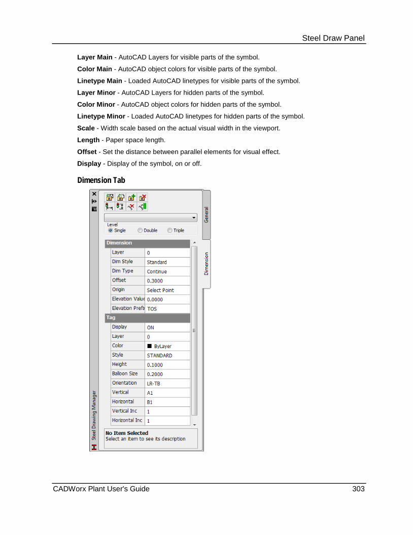
Steel Draw Panel Layer Main - AutoCAD Layers for visible parts of the symbol.
Color Main - AutoCAD object colors for visible parts of the symbol.
Linetype Main - Loaded AutoCAD linetypes for visible parts of the symbol.
Layer Minor - AutoCAD Layers for hidden parts of the symbol.
Color Minor - AutoCAD object colors for hidden parts of the symbol.
Linetype Minor - Loaded AutoCAD linetypes for hidden parts of the symbol.
Scale - Width scale based on the actual visual width in the viewport.
Length - Paper space length.
Offset - Set the distance between parallel elements for visual effect.
Display - Display of the symbol, on or off.
Dimension Tab
CADWorx Plant User's Guide 303

Steel Draw Panel Tools
Save Settings to File - Save your set of settings to an external file for use in another drawing.
Load Settings from File - Load a saved set of settings from a file into the drawing. Any existing named settings are lost when a new set is loaded from the file.
Add Named Style - Add a name to a set of settings you want to reuse.
Delete Named Style - Delete a named setting from the list.
Generate Plan Dimension - Generate the plan style dimensions of a selected viewport.
Generate Elevated Dimension - Generate the elevation style dimensions of a selected viewport.
Clear Dimensions - Remove all dimensions of a selected viewport.
Update Dimensions - Update existing dimensions of a selected viewport.
Settings List Box - Used to choose the named settings.
Dimension Level - Select how many dimension levels to use.
Dimension Settings
Layer - AutoCAD Layers
Dim Style - AutoCAD Dimension Styles.
Dim Type - Select the dimension type.
Baseline Type
Continue Type
Ordinate Type
304 CADWorx Plant User's Guide

Steel Draw Panel Offset - The distance from the edge of the viewport to place the first level dimensions. Elevation Value - The relative elevation of the selected origin point.
Elevation Prefix - Prefix for the elevation dimensions.
Tag Settings
Display - To display the column tags on the plan dimensions. Layer - AutoCAD Layer of the column tags and text. Color - AutoCAD color of the column tags and text. Style - Text style for the column tags and text. Height - Text height for the column tag text. Balloon Size - Diameter of the column tags. Orientation - The order of the automatic numbering of the column tags. LR-BT left to right, bottom to top LR-TB left to right, top to bottom RL-BT right to left, bottom to top RL-TB right to left, top to bottom Vertical - Vertical column tag numbering start and style. Letter (A) Letter + Number (A1) Number (1) Number + Letter (1A) Horizontal - Horizontal column tag numbering start and style. Letter (A) Letter + Number (A1) Number (1) Number + Letter (1A) Vertical Inc - The increment value of the tag number. Increments the second value of a combination tag Value = 1 then "A" to "B" or "A1" to "A2" Horizontal Inc - The increment value of the tag number. Increments the second value of a combination tag Value = 1 then "A" to "B" or "A1" to "A2"
CADWorx Plant User's Guide 305
Steel Draw Panel
Steel - Frame Creation CADWorx Steel / HVAC tab: Steel Draw > Frame Creation
Steel toolbar: Frame Creation
Plant menu: Steel > Frame > Creation
Command line: SFRAME
Create intelligent frames that you can use to build structural steel models.
Frame Creation Dialog Box Name - Specifies the name for the current frame. The frame name is required only when you create more than one frame in the same drawing. If you do not specify a name and you save the frame configuration, the software uses the file name as the frame name.
Specify On-screen - Select this option to specify the frame insertion point with your mouse. Clear this option to use the coordinate location specified in the X, Y, and Z boxes as the frame insertion location.
Repeat Rows/Columns - Select this option to repeat the same rows and columns as the first plan for all subsequent plans. This option provides a quick way to create large frames without repeatedly entering the same information. The setting of this option is saved with the frame configuration.
Create Clipped Views - Select this option to create clipped views for each plan, row, and column. These views can then be accessed using the View command in AutoCAD. The views are clipped in the front and back making them excellent to use in annotation layouts. You need to select the Update Layer option in the View command dialog for the view to be set correctly. The setting of this option is saved with the frame configuration.
Rotation Angle - Enter the rotation angle for the entire frame. The rotation is about the specified insertion point. The rotation angle is saved with the frame configuration.
Draw Sloped Vertical Lines - Select this option to make the vertical lines sloped according to each plans X and Y offsets. This option is useful when creating platform frames and requires that each plan have the same number of rows and columns. The setting of this option is saved with the frame configuration.
Plan - Defines the plans for the current frame. Specify the distance from one plan to the next in the Distance column for each plan. You can also specify X and Y offset values from the insertion point before the row and column lines for this plan are created.
CADWorx automatically creates labels for each plan based on the distance specified. The elevation label default setting is defined in [Product Folder]\System\FrameSetup.tbl with the PLAN_LABEL_START setting. Clear the Auto label option to define the label text yourself. The label is saved with the frame after it is drawn and is available for the Frame Annotation command. For more information, see Frame Annotation (on page 308).
Click Add to add a new plan to the current frame. Click Remove to delete the selected plans from the current frame. If Repeat Rows/Columns is not selected, Remove deletes all rows and columns associated with the plan that is being removed.
Row - Defines the rows for the current frame. You can specify the distance from one row to the next in the Distance column for each row. If Repeat Rows/Columns is selected, the rows are for the currently selected plan.
306 CADWorx Plant User's Guide
Steel Draw Panel CADWorx automatically creates labels for each row. The row label default setting is defined in [Product Folder]\System\FrameSetup.tbl. The [ROW] section contains the characters used in making the label. If there are more rows and available characters, the labels are concatenated. For example, A, B, C......X, Y, Z, AA, AB, AC and so on. Clear the Auto label option to define the label text yourself. This label is saved with the frame after it is drawn and is available for the Frame Annotation command. For more information, see Frame Annotation (on page 308).
Columns - Defines the columns for the current frame. You can specify the distance from one column to the next in the Distance column for each column. If Repeat Rows/Columns is selected, the columns are for the currently selected plan.
CADWorx automatically creates labels for each column. The column label default settings is defined in [Product Folder]\System\FrameSetup.tbl. The [COLUMN] section contains the characters used in making the label. If there are more columns than available characters, the labels are concatenated. For example, A, B, C......X, Y, Z, AA, AB, AC and so on. Clear the Auto label option to define the label text yourself. This label is saved with the frame after it is drawn and is available for the Frame Annotation command. For more information, see Frame Annotation (on page 308).
New - Click to create a new frame. You are prompted to save any changes to the current frame.
Save - Click to save the current frame to a file. You are prompted to enter a name and specify the location to save the frame configuration.
Save As - Click to save the current frame under a different file name.
OK - Click to draw the frame in the current drawing. You are prompted to save any changes to the current frame.
What do you want to do? Create a new frame configuration (on page 307)
Edit a frame configuration (on page 308)
Place a frame in the drawing (on page 308)
Create a new frame configuration 1. On the Steel Draw panel, click Frame Creation .
You can also type SFRAME in the command line.
The Frame Creation dialog box displays.
2. Define the insertion point for the frame.
3. Define the plans, rows, and columns using Add and Remove.
4. Click Save As.
5. Enter the frame name, and specify of folder location.
6. Click Save.
CADWorx Plant User's Guide 307
Steel Draw Panel
Edit a frame configuration 1. On the Steel Draw panel, click Frame Creation .
You can also type SFRAME in the command line. The Frame Creation dialog box displays.
2. Click Browse, and then open the frame to edit. 3. Edit the frame options and insertion point as needed. 4. Edit the plans, rows, and columns using Add and Remove. 5. Click Save.
Click Save As to save the frame to a different file.
Place a frame in the drawing 1. On the Steel Draw panel, click Frame Creation .
You can also type SFRAME in the command line. The Frame Creation dialog box displays.
2. Click Browse, and then open the frame to place. 3. Edit the frame options and insertion point as needed. 4. Edit the plans, rows, and columns using Add and Remove as needed. 5. Click OK.
You are prompted to save any edits that you have made to the frame.
Frame Annotation CADWorx Steel / HVAC tab: Steel Draw > Frame Annotation
Plant menu: Steel > Frame > Annotation
Command line: SFRAMEANOT
Annotates and dimensions frame lines. This command can also create the dimensions in call outs in paper space.
Dimensions only - Draws only the dimension for the selected frame line. You are prompted to pick the dimension side. The distance the dimensions are offset from the frame line is controlled by the AutoCAD setvar DIMDLI. This option respects the current DIMSCALE setting.
Call outs only - Creates the call out and places the label of the selected frame line in a block with attribute. The M5 block located in the [Product Directory]\Support folder is used for the call out. You are prompted to pick the call out location.
Both - This option creates both dimensions and call outs.
1. On the Steel Draw panel, click Frame Annotation .
You can also type SFRAMEANOT in the command line.
2. Select the frame line in the drawing.
3. Select Dimensions only, Call outs only, or Both.
4. Select the side of the frame line to place the annotation.
5. Pick the location of the annotation.
308 CADWorx Plant User's Guide
Steel Draw Panel
Ladder CADWorx Steel / HVAC tab: Steel Draw > Ladder
Steel toolbar: Ladder
Plant menu: Steel > Ladder
Command line: SLADDER
Creates ladders by specifying the start and end points of the ladder and rotation angle of the ladder. Click Browse to load a predefined ladder into the dialog box. Use Save As to save a ladder configuration for use later.
Position Tab Start point / End point - Defines the location of the ladder.
Specify On-screen - Select this option to specify the start and end ladder locations interactively in the model. Clear this option to define the locations using the X, Y, and Z coordinate boxes.
Rotation angle - Defines the rotation angle for the entire ladder. Select Specify On-screen to define the rotation interactively in the drawing. Clear the option to use the rotation value specified in the Angle box.
Dimension Tab Sloped ladder - Select to allow the ladder to be sloped. The slope is determined by the difference between the X or Y start and end locations in the Position Tab.
Rail width - Enter the inside distance from rail to rail.
Above platform - Enter the distance the ladder rails (offset extension of rail) are to extend above the top rung.
Rail top exit width - Enter the inside to inside distance of the ladder opening above the platform.
Rung spacing - Enter the center to center distance of the ladder rungs.
Offset (+/-) - Enter the distance the ladder is offset from the platform.
Cage Tab Cage ladder - Select to place a cage on the ladder if the height of the ladder is over the minimum distance.
Curved - Select to connect the hoop bars to the ladder using a curved connection.
Max. hoop spacing - Enter the distance from center to center of the intermediate hoops.
Cage bar spacing - Enter the distance from the center to center of the vertical bars on the cage.
Bottom hoop clearance - Enter the distance from the base elevation or grade to the bottom hoop.
Distance to middle - Enter the distance from the ladder rungs to the center of the cage.
Small hoop radius - Enter the radius of the hoop bar at the ladder rail location. This box is available only when Curved is selected.
CADWorx Plant User's Guide 309
Steel Draw Panel Connection distance - Enter the distance of the hoop bar at the ladder rail location. This box is available only when Curved is not selected.
Top hoop radius - Enter the radius of the top hoop from the center of the cage.
Intermediate hoop radius - Enter the radius of the intermediate hoop from the center of the cage.
Bottom hoop radius - Enter the radius of the bottom hoop from the center of the cage.
Top hoop opening - Defines the direction of the hoop opening. If you select Open Left or Open Right, you need to define the side outlet width and extension distances.
Side outlet width - Enter the width of the cage side opening.
Side outlet extension - Enter the length of the side outlet extension.
Sizes Tab The bars, rungs, hoops, and cage bars rows allows the selection of different components to be used with the ladder.
Type - Select the member type.
Data file - Select the data file to use. The data files that display are controlled by the SteelLibraryDirectory (on page 43) variable in the configuration settings.
Size - Select the member section size from the data file selected.
Details - Click the three-dots button to activate the Details dialog box. Using the Details dialog box, you can define annotations, offsets, rotations, and mirror the section.
Short annotation - Enter a description for the short annotation of the member. This annotation is used in bill of material reports.
Long annotation - Enter a description for the long annotation of the member. This annotation is used in bill of material reports.
X offset - Specify the member offset along the X-axis.
Remember that the base point is not always located at the centroid of the member.
Y offset - Specify the member offset along the Y-axis.
Rotation angle - Enter a rotation value in degrees for the member.
Mirror - Select to mirror the member about its base point.
What do you want to do? Place a ladder interactively (on page 311)
Place a ladder using key-ins (on page 311)
Place a ladder with a cage (on page 311)
310 CADWorx Plant User's Guide
Steel Draw Panel
Place a ladder interactively 1. On the Steel Draw panel, click Ladder .
You can also type SLADDER in the command line. The Ladder dialog box displays.
2. Optionally, click Browse, and then open the ladder configuration to place. 3. Select the Position tab. 4. Select the Specify On-screen option for the start and end points. 5. If needed, edit the ladder properties on the Dimension, Cage, and Size tabs. 6. Click OK. 7. If you edited properties, click Yes to save your changes for reuse. Click No to place the
ladder as defined but not to save the ladder properties for reuse. 8. Define the location of the ladder bottom. 9. Define the location of the ladder top.
Place a ladder using key-ins 1. On the Steel Draw panel, click Ladder .
You can also type SLADDER in the command line. The Ladder dialog box displays.
2. Optionally, click Browse, and then open the ladder configuration to place. 3. Select the Position tab. 4. Clear the Specify On-screen option for the start and end points. 5. Enter the ladder start and end points using the X, Y, and Z boxes. The bottom of the ladder
is defined on the left. The top of the ladder is defined on the right. 6. If needed, edit the ladder properties on the Dimension, Cage, and Size tabs. 7. Click OK. 8. If you edited properties, click Yes to save your changes for reuse. Click No to place the
ladder as defined but not to save the ladder properties for reuse. The ladder is placed in the drawing.
Place a ladder with a cage 1. On the Steel Draw panel, click Ladder .
You can also type SLADDER in the command line.
The Ladder dialog box displays.
2. Optionally, click Browse, and then open the ladder configuration to place.
3. Select the Cage tab.
4. Select the Caged ladder option.
5. If needed, edit the ladder properties on the Position, Dimension, and Size tabs.
6. Click OK.
7. If you edited properties, click Yes to save your changes for reuse. Click No to place the ladder as defined but not to save the ladder properties for reuse.
The ladder is placed in the drawing.
CADWorx Plant User's Guide 311

Steel Draw Panel
Handrail CADWorx Steel / HVAC tab: Steel Draw > Hand Rail
Steel toolbar: Hand Rail
Plant menu: Steel > Hand Rail
Command line: SHRAIL
Creates handrails in the drawing using specified corner points of the handrail or a polyline or 3D polyline that defines the path of the handrail. You are prompted to specify the offset direction after the points have been picked, or the polyline has been selected.
Dimensions Tab Post below platform (+/-) - Enter the distance to place the hand rail above or below the platform to which it is attached to. Platform offset dist (+/-) - Enter the distance to offset the hand rail. The hand rail can be offset away from or over the platform. Start/end offset - Enter the distance from the end of the hand rail to place the post or stanchion. This distance applies to both ends of the hand rail. Max post spacing - Enter the maximum distance between the post or stanchions. Spacing distance - Enter the vertical spacing between the rails. Use Add and Remove to change the number of rails. Sizes Tab The top rail, intermediate rail, bottom rail, and post can have different components for the hand rail. Type - Select the member type. Data file - Select the data file to use. The data files that display are controlled by the SteelLibraryDirectory (on page 43) variable in the configuration file. Size - Select the member section size from the data file selected. Details - Click the three-dots button to activate the Details dialog box. Using the Details dialog box, you can define annotations, offsets, rotations, and mirror the section. Short annotation - Enter a description for the short annotation of the member. This annotation is used in bill of material reports. Long annotation - Enter a description for the long annotation of the member. This annotation is used in bill of material reports. X offset - Specify the member offset along the X-axis.
Remember that the base point is not always located at the centroid of the member. Y offset - Specify the member offset along the Y-axis. Rotation angle - Enter a rotation value in degrees for the member. Mirror - Select to mirror the member about its base point.
What do you want to do? Place hand rail by points (on page 313)
Place hand rail by polyline (on page 313)
312 CADWorx Plant User's Guide
Steel Draw Panel
Place hand rail by points 1. On the Steel Draw panel, click Hand Rail .
You can also type SHRAIL in the command line.
The Hand Rail dialog box displays.
2. Optionally, click Browse, and then open a different hand rail configuration to place.
3. Edit the hand rail properties on the Dimension and Sizes tabs.
4. Click Pick points.
5. If you edited properties, click Yes to save your changes for reuse. Click No to place the hand rail as defined but not to save the hand rail properties for reuse.
6. Specify the starting location for the hand rail.
7. Continue placing vertex points for the hand rail path.
8. Right-click, and then select Enter.
9. Identify the path side that is away from the platform.
Place hand rail by polyline 1. Place a polyline or 3D polyline in the drawing that defines the hand rail path.
2. On the Steel Draw panel, click Hand Rail .
You can also type SHRAIL in the command line.
The Hand Rail dialog box displays.
3. Optionally, click Browse, and then open a different hand rail configuration to place.
4. Edit the hand rail properties on the Dimension and Sizes tabs.
5. Click Select line.
6. If you edited properties, click Yes to save your changes for reuse. Click No to place the hand rail as defined but not to save the hand rail properties for reuse.
7. Select the polyline in the drawing.
8. Identify the path side that is away from the platform.
Stair CADWorx Steel / HVAC tab: Steel Draw > Stair
Steel toolbar: Stair
Plant menu: Steel > Stair
Command line: SSTAIR
Creates stairs in the drawing by specifying the top point of the stair and then a base elevation.
CADWorx Plant User's Guide 313

Steel Draw Panel Position Tab Top point - Enter the X, Y, and Z coordinates for the top of the stairs. You can click Specified On-screen to select a point in the drawing.
Base elevation - Enter the elevation at the bottom of stringer. You can click Specified On-screen to select a point in the drawing.
Rotation angle - Enter the rotation in degrees. You can click Specified On-screen to define the rotation in the drawing.
Dimension Tab
Tread Boxes are disabled until the top point and bottom elevation are entered in the Position Tab. The software then calculates initial values based on the top point and bottom elevation.
Changes made to Recalculates
(A) Total rise (C) Rise
(B) Riser count (C) Rise, (E) Run
(C) Rise (A) Total rise
(D) First rise (C) Rise
(E) Run (F) Total run
(F) Total run (E) Run
(A) Total rise - Enter the distance between the bottom elevation and the top point.
(B) Riser count - Enter the number of risers (steps or treads) in the stair.
(C) Rise - Enter the distance between from the top of one riser to the top of the next riser.
(D) First rise - Enter the distance from the bottom elevation to the top of the first riser.
(E) Run - Enter the depth of the riser (if you were standing in front of the stair).
(F) Total Run - Enter the total length (measured horizontally) of the stair.
Stringer Width - Enter the inside distance between the two stringers.
(H) Top extend - Enter the distance between the stringer end and the riser.
(J) Top clear - Enter the distance between the top of the stringer and the top point defined for stair.
(K) Base extend - Enter the distance between the stringer end and the edge of the first riser.
(M) Base clear - Enter the distance between the bottom of the stringer and the bottom elevation point.
314 CADWorx Plant User's Guide
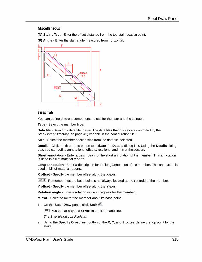
Steel Draw Panel Miscellaneous (N) Stair offset - Enter the offset distance from the top stair location point.
(P) Angle - Enter the stair angle measured from horizontal.
Sizes Tab You can define different components to use for the riser and the stringer.
Type - Select the member type.
Data file - Select the data file to use. The data files that display are controlled by the SteelLibraryDirectory (on page 43) variable in the configuration file.
Size - Select the member section size from the data file selected.
Details - Click the three-dots button to activate the Details dialog box. Using the Details dialog box, you can define annotations, offsets, rotations, and mirror the section.
Short annotation - Enter a description for the short annotation of the member. This annotation is used in bill of material reports.
Long annotation - Enter a description for the long annotation of the member. This annotation is used in bill of material reports.
X offset - Specify the member offset along the X-axis.
Remember that the base point is not always located at the centroid of the member.
Y offset - Specify the member offset along the Y-axis.
Rotation angle - Enter a rotation value in degrees for the member.
Mirror - Select to mirror the member about its base point.
1. On the Steel Draw panel, click Stair .
You can also type SSTAIR in the command line.
The Stair dialog box displays.
2. Using the Specify On-screen button or the X, Y, and Z boxes, define the top point for the stairs.
CADWorx Plant User's Guide 315

Steel Draw Panel 3. Using the Specify On-screen button or the Z box, define the base elevation for the stairs.
4. Using the Specify On-screen button or the Angle box, define the rotation for the stairs.
5. Select the Dimension tab.
6. Review and edit the tread and stringer properties as needed. Refer to Dimension Tab if needed.
7. Select the Sizes tab.
8. Define the components sizes for the treads and the stringers.
9. Click OK.
316 CADWorx Plant User's Guide

S E C T I O N 1 9
CADWorx Steel / HVAC > Steel Edit
Command Description Command line
Cope - Cuts a member back to other members. For more information, see Steel - Cope (on page 318).
SCOPE
Miter - Cuts two coplanar members back to one another. For more information, see Miter (on page 318).
SMITER
Cut - Cuts members by a plane that you define. For more information, see Cut (on page 319).
SCUT
Union - Joins two members. For more information, see Union (on page 320).
SUNION
Local Edit - Edits a selected member. For more information, see Edit (on page 320).
SCEDIT
Global Edit - Edits the annotation, description, part number, and material of multiple components. For more information, see Global Edit (on page 325).
SGCEDIT
Global Edit All - Edits multiple components of the same member shape. For more information, see Global Edit All (on page 325).
SGCEDITALL
Annotate Component - Places the long or short annotation of the component in the drawing. For more information, see Annotate Component (on page 328).
SCOMPANOT
Convert Solid - Converts components to solids. For more information, see Convert Solid (on page 328).
SCONVERTSOLID
Layer Change - Moves steel solid or center lines to a new layer. For more information, see Layer Change (on page 328).
SLAYERCHANGE / SSETEXIST / SREMOVEEXIST
Selection Control - Toggles the display of grips on and off. For more information, see Select Control (on page 329).
SELECTCONTROL
Auto Cope - Turns on or off the automatic coping of members. For more information, see Auto Cope (on page 329).
SAUTOCOPE
Steel Edit Panel
CADWorx Plant User's Guide 317

Steel Edit Panel
Steel - Cope CADWorx Steel / HVAC tab: Steel Edit > Cope
Steel toolbar: Cope
Plant menu: Steel > Cope
Command line: SCOPE
Copes steel members to other steel members. You can place bolted coping or welded coping. Bolted coping is controlled by SteelCopeBoltDistance (on page 43) and provides a gap between the coped member and the boundary member. Welded cope is controlled by SteelCopeWeldDistance (on page 43) and provides a gap between the coped member and the boundary member. You can:
Cope a single member to another single member that provides the cope boundary.
Cope many members to many other members.
A member that crosses another member is cut into two separate members.
1. On the Steel Edit panel, click Cope .
You can also type SCOPE in the command line.
2. Select the members to cope. Press ENTER or right-click when you are finished.
3. Select the members to cope against. Press ENTER or right-click when you are finished.
4. Select bolted or welded cope.
Bolt - Copes the members with the offset specified in the SteelCopeBoltDistance startup variable.
Weld - Copes the members with the offset specified in the SteelCopeWeldDistance startup variable.
Miter CADWorx Steel / HVAC tab: Steel Edit > Miter
Steel toolbar: Miter
Plant menu: Steel > Miter
Command line: SMITER
Miters two structural pieces to fit each other. The two structural pieces must be in the same plane and have connected member ends. You miter multiple member pairs in each command pass.
1. On the Steel Edit panel, click Miter .
You can also type SMITER in the command line.
2. Select the members to miter.
3. Press ENTER or right-click when you are finished.
The software miters the selected members.
318 CADWorx Plant User's Guide

Steel Edit Panel
Cut CADWorx Steel / HVAC tab: Steel Edit > Cut
Steel toolbar: Cut
Plant menu: Steel > Cut
Command line: SCUT
Cuts steel members along a plane that you define by an existing line or by points placed in the drawing. The software updates the lengths, weight, and other affected properties of the cut members. You cannot cut plate members with this command.
Line - Defines the plane using the two end points of the line and its extrusion direction (the Z-axis of the plane the line was drawn in).
Points - Defines the plane using three points you pick in the drawing.
What do you want to do? Cut members by line (on page 319)
Cut members by three-point plane (on page 319)
Cut members by line 1. On the Steel Edit panel, click Cut .
You can also type SCUT in the command line.
2. Select Line.
3. Select the line to use to define the plane.
4. Select the members to cut.
5. Right-click or press ENTER to cut the members.
Cut members by three-point plane 1. On the Steel Edit panel, click Cut .
You can also type SCUT in the command line.
2. Select Points.
3. Pick three points in the drawing to define the cutting plane.
4. Select the members to cut.
5. Right-click or press ENTER to cut the members.
CADWorx Plant User's Guide 319

Steel Edit Panel
Union CADWorx Steel / HVAC tab: Steel Edit > Union
Steel toolbar: Union
Plant menu: Steel > Union
Command line: SUNION
Joins two or more steel members into one member. The members must have the same properties for:
Member size (W10x30 for example)
Insertion location
Centerline location
Rotation angle
Data file
Short annotation
Long annotation
Description
Material
Part number
In addition, the two center lines must meet each other but not intersect or overlap.
Curved members cannot be joined with straight members.
1. On the Steel Edit panel, click Union .
You can also type SUNION in the command line.
2. Select the first member to join.
3. Select the second member to join.
4. Continue to select members. When you are finished, right-click or press ENTER to join the members.
Edit CADWorx Steel / HVAC tab: Steel Edit > Edit
Steel toolbar: Edit
Plant menu: Steel > Component Edit > Local Edit
Command line: SCEDIT
Edits the properties of steel shapes and plates in the drawing. You can start this command from the command line, the command icon, or by double-clicking the object you want to edit.
320 CADWorx Plant User's Guide

Steel Edit Panel Draw Steel Dialog Box Select Type - Select the shape to place. The drop down lists each folder defined by the SteelLibraryDirectory (on page 43) startup variable. In each folder is a Type.ini file specifying the member type in that folder (W, T, TS, and so forth).
Select Data File - Select the data file that contains the component to place. All the data files located in the folder defined by the SteelLibraryDirectory (on page 43) startup variable display for selection. You can have a mix of metric and imperial data files in the same folder. CADWorx automatically converts the selected data file to the proper drawing units.
Select Member - Specifies the member to use. The delivered data files have members in alphabetical order. You can edit the data files to have the members in any order.
Rotation Angle - Select the component rotation about the centerline. You can select 0, 90, 180, 270, or type the needed rotation angle. Do not use AutoCAD commands (ROTATE, MIRROR, 3DROTATE) to change the rotation angle of the shape. The rotation angle of the shape can only be set from the Draw Steel dialog box.
Pick Insertion Location - Click to select the insertion point. The red box indicates the active location.
Centerline location - Select the top, center, or bottom location of the centerline relative to the component shape. The centerline location can only be along the three locations on the Y-axis of the component.
Use UCS - Select to use the current UCS as the XY plane. For example, if the UCS is located in the same plane as a slope roof, components are easily added at this angle if you select this option. Select two points within the plane to determine the rotation automatically.
Existing - Edits the existing status of the plate.
Short Annotation - Defines the short annotation name for the component. The default value is the text in the MEMBER column of the data file up to the first "X" character.
Long Annotation - Defines the long annotation name for the component. The default value is the text in the MEMBER column of the data file.
Description - Defines the component description. The default value is the "DESCRIPTION=" value in the data file header.
Part Number - Specifies the part number for the component. You can enter the part number yourself or use the part number automatically assigned by the SteelPartNumberFile (on page 44) startup variable.
Material - Specifies the material for the component. The default value is the "MATERIAL=" value in the data file header.
Pick Points - Click to define the component by two points on the screen.
Select Lines - Click to select lines in the drawing to place the component. The length and position of the line define the component.
Properties - Activates the Properties dialog box that you can use to edit the shape properties before placement. For more information, see Properties Dialog Box.
User Input - Activates the User Input dialog box that you can use to create a custom-dimensioned shape. Select a shape that is close to the size you need before clicking User Input. For more information, see User Input Dialog Box.
CADWorx Plant User's Guide 321

Steel Edit Panel Properties Dialog Box Displays the available properties of the selected member.
The reference data file path and file name is shown at the top.
Weight - Displays the weight of the component. Select Manual Update to enter the weight yourself.
Length - Displays the length of the component. Select Manual Update to enter the length yourself. The component length is calculated based on the shape of the solid, not the length of the centerline. For example, if one end of the component is cut 45 degrees, the full length would be to the very end of the 45 degree cut, not the centerline length.
The top grid displays the required properties to place the shape. Do not add to or edit the order of these properties in the data file or the component does not place correctly in the drawing.
The bottom grid displays the optional properties. You can add or remove properties in the data file as needed. For example, you might want to add a column in the data file for the gage distance.
User Input Dialog Box Defines custom dimensioned components.
Dimensions - Displays the dimensions that you can define. Refer to the figure for a key of which dimension is which.
Rotation Angle - Select the component rotation about the centerline or base point. You can select 0, 90, 180, 270, or type the needed rotation angle.
Short Annotation - Defines the short annotation name for the component.
Long Annotation - Defines the long annotation name for the component. The thickness, length, and width dimensions are appended to the long annotation as the component is drawn and placed.
Description - Defines the component description.
Density - Defines the material density for the component.
Draw Plate Dialog Box Select Data File - Select the data file that contains the component to place. All the data files located in the folder defined by the SteelLibraryDirectory (on page 43) startup variable display for selection. You can have a mix of metric and imperial data files in the same folder. CADWorx automatically converts the selected data file to the proper drawing units.
Select Member - Specifies the member to use. The delivered data files have members in alphabetical order. You can edit the data files to have the members in any order.
Existing - Edits the existing status of the plate.
Short Annotation - Defines the short annotation name for the plate. The default value is the text in the MEMBER column of the data file up to the first "X" character.
Long Annotation - Defines the long annotation name for the plate. The default value is the text in the MEMBER column of the data file.
Description - Defines the plate description. The default value is the "DESCRIPTION=" value in the data file header.
322 CADWorx Plant User's Guide
Steel Edit Panel Part Member - Specifies the part number for the plate. You can enter the part number yourself or use the part number automatically assigned by the SteelPartNumberFile (on page 44) startup variable.
Material - Specifies the material for the plate. The default value is the "MATERIAL=" value in the data file header.
Length - Displays the length of the plate computed by finding a bounding box around the plate aligned along an alignment axis. The alignment axis through the plate is the axis formed by the long segment of the polyline used to create the plate.
Width - Displays the width of the plate computed by finding a bounding box around the plate aligned along an alignment axis. The alignment axis through the plate is the axis formed by the long segment of the polyline used to create the plate.
Weight - Displays the weight of the plate. Select Manual Update to enter the value yourself.
Manual Update - Select this option to manually specify the plate weight in the Weight box. Clear this option to have the software compute the plate weight using the shape and the weight defined in the data file.
Insert Location - Select the centerline location for the plate. This option is only available when editing an existing plate in the model.
Pick Points - Click to define the plates by its corners.
Select Lines - Click to define the plate using an existing closed polyline shape.
Select Curves - Click to define the plate using an existing closed curved shape.
Base Plate Dialog Box Select Data File - Select the data file that contains the component to place. All the data files located in the folder defined by the SteelLibraryDirectory (on page 43) startup variable display for selection. You can have a mix of metric and imperial data files in the same folder. CADWorx automatically converts the selected data file to the proper drawing units.
Select Member - Specifies the member to use. The delivered data files have members in alphabetical order. You can edit the data files to have the members in any order.
Details Existing - Edits the existing status of the plate.
Short annotation - Defines the short annotation name for the plate. The default value is the text in the MEMBER column of the data file up to the first "X" character.
Long annotation - Defines the long annotation name for the plate. The default value is the text in the MEMBER column of the data file.
Description - Defines the plate description. The default value is the "DESCRIPTION=" value in the data file header.
Part number - Specifies the part number for the plate. You can enter the part number yourself or use the part number automatically assigned by the SteelPartNumberFile (on page 44) startup variable.
Material - Specifies the material for the plate. The default value is the "MATERIAL=" value in the data file header.
CADWorx Plant User's Guide 323

Steel Edit Panel Weight - Displays the weight of the plate. The software automatically subtracts the material weight removed by any holes from the plate weight. Select Manual Update to enter the value yourself.
Manual Update - Select this option to manually specify the plate weight in the Weight box. Clear this option to have the software compute the plate weight using the shape and the weight defined in the data file.
Plate Dimensions Length - Displays the length of the plate computed by finding a bounding box around the plate aligned along an alignment axis. The alignment axis through the plate is the axis formed by the long segment of the polyline used to create the plate.
Width - Displays the width of the plate computed by finding a bounding box around the plate aligned along an alignment axis. The alignment axis through the plate is the axis formed by the long segment of the polyline used to create the plate.
Rotation - Specifies the rotation angle for the plate placement.
X offset - Specifies the X-axis offset from the plate centroid.
Y offset - Specifies the Y-axis offset from the plate centroid.
Hole Dimensions On/Off - Select this option to place holes in the base plate. Clear this option to place a plate without holes.
Row count - Enter the number of hole rows.
Row spacing - Enter the distance between the hole rows measured from the center of the holes.
Column count - Enter the number of hole columns.
Column spacing - Enter the distance between the hole columns measured from the center of the holes.
Diameter - Enter the diameter of the hole.
Rotation - Enter the angle at which to rotate the hole rows and columns within the base plate.
Slotted length - Enter a distance to create an elongated hole. This distance is measured from the hole center.
X offset - Specifies the X-axis offset for the holes. Holes places at zero offset are at the base plate center.
Y offset - Specifies the Y-axis offset for the holes. Holes places at zero offset are at the base plate center.
Pick Point - Click to place the base plate.
324 CADWorx Plant User's Guide

Steel Edit Panel
Global Edit CADWorx Steel / HVAC tab: Steel Edit > Global Edit
Plant menu: Steel > Component Edit > Global Edit
Command line: SGCEDIT
Edits short annotation, long annotation, description, part number, and material for multiple components at one time. Changes to any or all of the edit boxes are made to each selected component. Leave the edit boxes blank for those properties you do not want to edit.
Steel Global Edit Dialog Box Short Annotation - Defines the short annotation name. Generally, this is the member name up to the first "X" character (for example, W10 is the short annotation name for W10X30).
Long Annotation - Defines the long annotation name (for example, W10X30).
Description - Defines the component description.
Part Member - Specifies the part number for the component.
Material - Specifies the material for the component.
1. On the Steel Edit panel, click Global Edit .
You can also type SGCEDIT in the command line.
2. Select the members to edit. Press ENTER or right-click when you are finished.
The Steel Global Edit dialog box displays.
3. Edit the appropriate property boxes. Leave blank the properties that you do not want to change.
4. Click OK.
Global Edit All CADWorx Steel / HVAC tab: Steel Edit > Global Edit All
Plant menu: Steel > Component Edit > Global Edit All
Command line: SGCEDITALL
Edits multiple components of the same member shape. After selecting multiple components or maybe your entire drawing, you can filter the component to edit by member shape.
Draw Steel Dialog Box Select Type - Select the shape to place. The drop down lists each folder defined by the SteelLibraryDirectory (on page 43) startup variable. In each folder is a Type.ini file specifying the member type in that folder (W, T, TS, and so forth).
Select Data File - Select the data file that contains the component to place. All the data files located in the folder defined by the SteelLibraryDirectory (on page 43) startup variable display for selection. You can have a mix of metric and imperial data files in the same folder. CADWorx automatically converts the selected data file to the proper drawing units.
CADWorx Plant User's Guide 325

Steel Edit Panel Select Member - Specifies the member to use. The delivered data files have members in alphabetical order. You can edit the data files to have the members in any order.
Rotation Angle - Select the component rotation about the centerline. You can select 0, 90, 180, 270, or type the needed rotation angle. Do not use AutoCAD commands (ROTATE, MIRROR, 3DROTATE) to change the rotation angle of the shape. The rotation angle of the shape can only be set from the Draw Steel dialog box.
Pick Insertion Location - Click to select the insertion point. The red box indicates the active location.
Centerline location - Select the top, center, or bottom location of the centerline relative to the component shape. The centerline location can only be along the three locations on the Y-axis of the component.
Use UCS - Select to use the current UCS as the XY plane. For example, if the UCS is located in the same plane as a slope roof, components are easily added at this angle if you select this option. Select two points within the plane to determine the rotation automatically.
Existing - Edits the existing status of the plate.
Short Annotation - Defines the short annotation name for the component. The default value is the text in the MEMBER column of the data file up to the first "X" character.
Long Annotation - Defines the long annotation name for the component. The default value is the text in the MEMBER column of the data file.
Description - Defines the component description. The default value is the "DESCRIPTION=" value in the data file header.
Part Number - Specifies the part number for the component. You can enter the part number yourself or use the part number automatically assigned by the SteelPartNumberFile (on page 44) startup variable.
Material - Specifies the material for the component. The default value is the "MATERIAL=" value in the data file header.
Pick Points - Click to define the component by two points on the screen.
Select Lines - Click to select lines in the drawing to place the component. The length and position of the line define the component.
Properties - Activates the Properties dialog box that you can use to edit the shape properties before placement. For more information, see Properties Dialog Box.
User Input - Activates the User Input dialog box that you can use to create a custom-dimensioned shape. Select a shape that is close to the size you need before clicking User Input. For more information, see User Input Dialog Box.
Properties Dialog Box Displays the available properties of the selected member.
The reference data file path and file name is shown at the top.
Weight - Displays the weight of the component. Select Manual Update to enter the weight yourself.
326 CADWorx Plant User's Guide

Steel Edit Panel Length - Displays the length of the component. Select Manual Update to enter the length yourself. The component length is calculated based on the shape of the solid, not the length of the centerline. For example, if one end of the component is cut 45 degrees, the full length would be to the very end of the 45 degree cut, not the centerline length.
The top grid displays the required properties to place the shape. Do not add to or edit the order of these properties in the data file or the component does not place correctly in the drawing.
The bottom grid displays the optional properties. You can add or remove properties in the data file as needed. For example, you might want to add a column in the data file for the gage distance.
1. On the Steel Edit panel, click Global Edit All .
You can also type SGCEDITALL in the command line.
2. Select the members to edit. Press ENTER or right-click when you are finished.
The Steel Global Edit dialog box displays.
3. Select the member shapes you want to edit. You can select more than one group to edit,
although you edit the groups one at a time.
4. Click OK.
The Component Edit dialog box displays.
5. Edit the member properties as needed. See Draw Steel Dialog Box for more information about this dialog.
6. Click OK.
The software displays the number of components that were updated.
7. If you selected more than one group, the Component Edit dialog box displays the next group.
8. Edit the member properties as needed.
9. Click OK.
CADWorx Plant User's Guide 327
Steel Edit Panel
Annotate Component CADWorx Steel / HVAC tab: Steel Edit > Annotate Component
Command line: SCOMPANOT
Places the short or long annotations of selected steel members in the drawing.
1. On the Steel Edit panel, click Annotate Component .
You can also type SCOMPANOT in the command line.
2. Select the component to annotate. Type Auto to have the software automatically determine the annotation rotation and location. Press ENTER or right-click when you are finished.
3. Select Long to place the defined long annotation.
or
Select Short to place the defined short annotation.
4. Define the annotation starting location.
5. Define the annotation rotation.
Convert Solid CADWorx Steel / HVAC tab: Steel Edit > Convert Solid
Command line: SCONVERTSOLID
Creates the solid representation of component. When you have deleted the solid representation and have been modeling using only centerlines, this command is used to re-create the solid cross-section representation of the component.
1. On the Steel Edit panel, click Convert Solid .
You can also type SCONVERTSOLID in the command line.
2. Select the components to convert. Press ENTER or right-click when you are finished.
The software creates the solids.
Layer Change CADWorx Steel / HVAC tab: Steel Edit > Layer Change
Command line: SLAYERCHANGE / SSETEXIST / SREMOVEEXIST
Edits the existing flag for steel members and changes layers for steel solid and centerline graphics.
The software automatically moves steel plates and base plates centerlines to whichever layer is chosen for the corresponding solid.
1. On the Steel Edit panel, click Layer Change .
You can also type SLAYERCHANGE in the command line.
328 CADWorx Plant User's Guide

Steel Edit Panel 2. Select All to select all components in the drawing.
-or- Select Select to manually select steel members. Press ENTER or right-click when you are finished.
3. Select Yes to change the solid layer of the selected components.
4. Select the new layer, and then click OK.
5. Select Yes to change the centerline layer of the selected components.
6. Select the new layer, and then click OK.
Select Control CADWorx Steel / HVAC tab: Steel Edit > Select Control
Command line: SELECTCONTROL
Toggles whether grip points are displayed on solids. To change the length of pipe or steel, you can grip stretch the pipe or steel centerline. However, it may be difficult to select the center line endpoint grip for steel shapes when solid grip points are on. Turning off the solid grip points with this toggle makes it easier to grip stretch components.
Auto Cope CADWorx Steel / HVAC tab: Steel Edit > Auto Cope
Steel toolbar: Auto Cope
Plant menu: Steel > Auto Cope
Command line: SAUTOCOPE
Toggles the automatic coping of members on or off. When two members are coped and this feature is on, the software automatically reapplies the cope when one of the members changes. Select this command again to turn off the automatic coping feature.
CADWorx Plant User's Guide 329

Steel Edit Panel
330 CADWorx Plant User's Guide
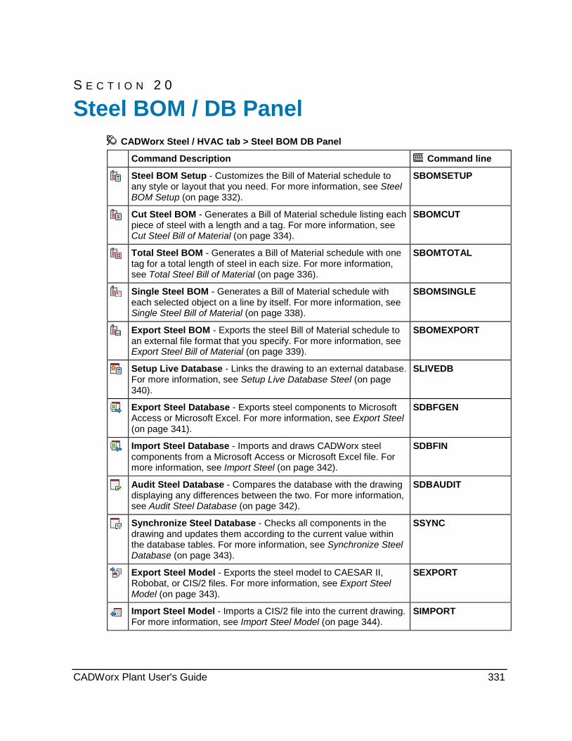
S E C T I O N 2 0
CADWorx Steel / HVAC tab > Steel BOM DB Panel
Command Description Command line
Steel BOM Setup - Customizes the Bill of Material schedule to any style or layout that you need. For more information, see Steel BOM Setup (on page 332).
SBOMSETUP
Cut Steel BOM - Generates a Bill of Material schedule listing each piece of steel with a length and a tag. For more information, see Cut Steel Bill of Material (on page 334).
SBOMCUT
Total Steel BOM - Generates a Bill of Material schedule with one tag for a total length of steel in each size. For more information, see Total Steel Bill of Material (on page 336).
SBOMTOTAL
Single Steel BOM - Generates a Bill of Material schedule with each selected object on a line by itself. For more information, see Single Steel Bill of Material (on page 338).
SBOMSINGLE
Export Steel BOM - Exports the steel Bill of Material schedule to an external file format that you specify. For more information, see Export Steel Bill of Material (on page 339).
SBOMEXPORT
Setup Live Database - Links the drawing to an external database. For more information, see Setup Live Database Steel (on page 340).
SLIVEDB
Export Steel Database - Exports steel components to Microsoft Access or Microsoft Excel. For more information, see Export Steel (on page 341).
SDBFGEN
Import Steel Database - Imports and draws CADWorx steel components from a Microsoft Access or Microsoft Excel file. For more information, see Import Steel (on page 342).
SDBFIN
Audit Steel Database - Compares the database with the drawing displaying any differences between the two. For more information, see Audit Steel Database (on page 342).
SDBAUDIT
Synchronize Steel Database - Checks all components in the drawing and updates them according to the current value within the database tables. For more information, see Synchronize Steel Database (on page 343).
SSYNC
Export Steel Model - Exports the steel model to CAESAR II, Robobat, or CIS/2 files. For more information, see Export Steel Model (on page 343).
SEXPORT
Import Steel Model - Imports a CIS/2 file into the current drawing. For more information, see Import Steel Model (on page 344).
SIMPORT
Steel BOM / DB Panel
CADWorx Plant User's Guide 331
Steel BOM / DB Panel
Steel BOM Setup CADWorx Steel / HVAC tab: Steel BOM / DB > Setup
Plant menu: Steel > Bill of Material > Setup
Command line: SBOMSETUP
Customizes the Bill of Material schedule to any style or layout that you need. Using this dialog box, you can specify column widths, provide the schedule direction (up or down), provide user specified headings for columns, allow alignment of columns, and the selection of different entries into the schedule. You can arrange the columns in any order.
Bill of Material lengths are based on DIMLFAC, DIMDEC, and DIMLUNIT.
Steel Bill of Material Setup Dialog Box Defines or edits the Bill of Material (BOM) schedule template. The template is stored in the configuration file listed at the top of the dialog.
BOM Columns Available - Lists all the information on a steel member that you can include in the BOM. These columns can be added to any schedule template in any order using Add.
BOM Columns Selected - Shows all the columns that have been selected and their order of appearance in the schedule from left (top of list box) to right (bottom of list box). Use Sort Order to set the order by which these columns are sorted.
Add and Remove - Moves selected columns between the BOM Columns Available and BOM Columns Selected lists. You can also move a column to the other list by double-clicking on the column name in the list.
Alignment - Specifies the text alignment for the selected column.
Grow Direction - Specifies whether the schedule should start at the top and work its way down or start at the bottom and work its way up.
Move Up and Move Down - Defines the column order in the BOM. Select a column in the BOM Columns Selected list, and then click Move Up to place the column further left in the BOM. Click Move Down to place the selected column further right in the BOM.
Move Up and Move Down do not set the sort order of the BOM, only the placement of the columns. Use Sort Order to define the sort order.
Column title - Specifies the text heading for the selected column.
Column width - Specifies the width for the selected column.
Sort Order - Controls the sort order and accumulation of steel components in the BOM. For more information, see Steel BOM Sort Order / Accumulation Dialog Box (on page 334).
What do you want to do? Add or remove properties from BOM (on page 333)
Change the column order (on page 333)
Change text alignment in columns (on page 333)
Change the BOM sorting and accumulation (on page 333)
332 CADWorx Plant User's Guide
Steel BOM / DB Panel
Add or remove properties from BOM 1. On the Steel BOM / DB panel, click Setup .
You can also type SBOMSETUP in the command line.
The Steel Bill of Material Setup dialog box displays.
2. To add a property to the BOM, double-click the property in the BOM Columns Available list.
Use the Column title and Column width boxes to define the column heading text and the column width respectively.
3. To remove a property from the BOM, double-click the property in the BOM Columns Selected list.
4. Click OK.
Change the column order 1. On the Steel BOM / DB panel, click Setup .
You can also type SBOMSETUP in the command line.
The Steel Bill of Material Setup dialog box displays.
2. Select the column to move in the BOM Columns Selected list.
3. Use Move Up and Move Down to change the column order. The column order in the list top to bottom is the column order in the BOM from left to right.
4. Click OK.
Change text alignment in columns 1. On the Steel BOM / DB panel, click Setup .
You can also type SBOMSETUP in the command line.
The Steel Bill of Material Setup dialog box displays.
2. Select the column to edit in the BOM Columns Selected list.
3. Select Left, Center, or Right to control the vertical text justification in the selected column.
4. Select Downward or Upward to control the horizontal alignment of the text in the selected column.
5. Click OK.
Change the BOM sorting and accumulation 1. On the Steel BOM / DB panel, click Setup .
You can also type SBOMSETUP in the command line.
The Steel Bill of Material Setup dialog box displays.
2. Click Sort Order.
The Steel BOM Sort Order / Accumulation Control Setup dialog box displays.
CADWorx Plant User's Guide 333

Steel BOM / DB Panel 3. Move the columns that you want to sort with to the BOM Columns Selected list.
4. Use Move Up and Move Down to specify which columns are sorted first in the BOM.
5. Select a column and use the Ascending and Descending options to control how information in that column is sorted. Ascending means sorting from small numbers to larger numbers (1 to 100) and from A to Z. Descending is large number to smaller (100 to 1) and Z to A.
6. Click OK on the Steel BOM Sort Order dialog box.
7. Click OK on the Steel Bill of Material Setup dialog box.
Steel BOM Sort Order / Accumulation Dialog Box Controls the sort order of the BOM. Columns that you place in the BOM Columns Selected list are used to sort the BOM starting with the top column, then the second column, and so forth. Use Move Up and Move Down to change the order in which the BOM is sorted.
This dialog box also controls the accumulation of steel components. For example, if two members have different Short Annotation values and you do not want these to accumulate, Short Annotation would have to be added to the BOM Columns Selected list.
BOM Columns Available - Lists all the information on a steel member that you can use to sort the BOM. These columns can be used to sort using Add. BOM Columns Selected - Shows all the columns that have been selected for sorting and their sort order from top to bottom. Add and Remove - Moves selected columns between the BOM Columns Available and BOM Columns Selected lists. You can also move a column to the other list by double-clicking on the column name in the list. Column Sort - Controls additional sorting on each selected column. Ascending means sorting from small numbers to larger numbers (1 to 100) and from A to Z. Move Up and Move Down - Defines the sort order in the BOM. Select a column in the BOM Columns Selected list, and then click Move Up to sort that column before other columns. Click Move Down to sort the column after columns higher in the list.
Cut Steel Bill of Material CADWorx Steel / HVAC tab: Steel BOM / DB > Cut
Plant menu: Steel > Bill of Material > Run > Cut
Command line: SBOMCUT
Generates a Bill of Material schedule listing each piece of steel with a length and a tag. Identical items are accumulated in the quantity column. For example, if you select two W14X74 components that are both 120 feet long, the BOM looks like this:
BILL OF MATERIALS
MARK QTY LONG ANNOTATION LENGTH WEIGHT
1 2 W14X74 120.00 1480.00
TOTAL WEIGHT: 1480.00
334 CADWorx Plant User's Guide

Steel BOM / DB Panel The steel component could have been converted with the Existing option.
Bill of material lengths are based on DIMLFAC, DIMDEC, and DIMLUNIT. Counter - Select this option to start the tag counter at any positive nonzero integer. When set, the command resumes requesting that you pick Manual placement or Automatic placement of tags. Manual placement - Select to insert tags manually. You are prompted for the tag location. The software adds a rubber band line attached to the component extending to the specified tag location. You must continue specifying locations until the last component’s tag has been placed. Automatic placement - Select to have CADWorx insert tags automatically. In model space, CADWorx places the tag in the direction (tag to component) provided. In paper space, this prompt does not appear if the tag optimization is on. For more information, see BomTagOptimize (on page 35). The schedule's text size is based on the AutoCAD setvar TEXTSIZE. If this text size is larger than the schedule spacing, the following message appears and the Bill of Material generation stops. The schedule spacing is controlled by the BomScheduleSpacing (on page 34) variable in the Configuration Settings.
A common mistake in AutoCAD is to apply a text height while setting up a text style. If the
height is specified in the text style dialog, then there is no other way of controlling the size. The text size is set to the size in the dialog regardless of what the TEXTSIZE variable is set to. CADWorx performs special optimization for automatic tag placement while in paper space only. This optimization places tags in non-overlapping positions and is controlled by the BomTagOptimize variable in the current configuration settings. For more information regarding this functionality and its controls, see BomTagOptimize (on page 35).
What do you want to do? Cut BOM using Automatic placement (on page 335)
Cut BOM using Manual placement (on page 336)
Cut BOM using Automatic placement 1. On the Steel BOM / DB panel, click Cut .
You can also type SBOMCUT in the command line. 2. Select the Automatic placement option. 3. Enter the placement angle for the tag. 4. Specify a point in the drawing for the upper right corner of the BOM schedule. 5. Select the steel components to include in the BOM. Right-click or press ENTER when you
are finished. The BOM is generated.
CADWorx Plant User's Guide 335
Steel BOM / DB Panel
Cut BOM using Manual placement 1. On the Steel BOM / DB panel, click Cut .
You can also type SBOMCUT in the command line.
2. Select the Manual placement option.
3. Specify a point in the drawing for the upper right corner of the BOM schedule.
4. Select the steel components to include in the BOM. Right-click or press ENTER when you are finished.
5. Specify the tag location for each component you selected.
The BOM is generated.
Total Steel Bill of Material CADWorx Steel / HVAC tab: Steel BOM / DB > Total
Plant menu: Steel > Bill of Material > Run > Total
Command line: SBOMTOTAL
Generates a Bill of Material schedule with one tag for a total length of steel in each size. Identical long annotation items are accumulated in the length column. For example, if you select two W14X74 components that are both 120 feet long, the BOM looks like this:
BILL OF MATERIALS
MARK QTY LONG ANNOTATION LENGTH WEIGHT
1 1 W14X74 240.00 1480.00
TOTAL WEIGHT: 1480.00
The component could have been converted with the Existing option.
Bill of material lengths are based on DIMLFAC, DIMDEC, and DIMLUNIT.
Counter - Select this option to start the tag counter at any positive nonzero integer. When set, the command resumes requesting that you pick Manual placement or Automatic placement of tags.
Manual placement - Select to insert tags manually. You are prompted for the tag location. The software adds a rubber band line attached to the component extending to the specified tag location. You must continue specifying locations until the last component’s tag has been placed.
Automatic placement - Select to have CADWorx insert tags automatically. In model space, CADWorx places the tag in the direction (tag to component) provided. In paper space, this prompt does not appear if the tag optimization is on. For more information, see BomTagOptimize (on page 35).
336 CADWorx Plant User's Guide

Steel BOM / DB Panel The schedule's text size is based on the AutoCAD setvar TEXTSIZE. If this text size is larger than the schedule spacing, the following message appears and the Bill of Material generation stops. The schedule spacing is controlled by the BomScheduleSpacing (on page 34) variable in the Configuration Settings.
A common mistake in AutoCAD is to apply a text height while setting up a text style. If the
height is specified in the text style dialog, then there is no other way of controlling the size. The text size is set to the size in the dialog regardless of what the TEXTSIZE variable is set to.
CADWorx performs special optimization for automatic tag placement while in paper space only. This optimization places tags in non-overlapping positions and is controlled by the BomTagOptimize variable in the current configuration settings. For more information regarding this functionality and its controls, see BomTagOptimize (on page 35).
What do you want to do? Total BOM using Automatic placement (on page 337) Total BOM using Manual placement (on page 337)
Total BOM using Automatic placement 1. On the Steel BOM / DB panel, click Total .
You can also type SBOMTOTAL in the command line. 2. Select the Automatic placement option. 3. Enter the placement angle for the tag. 4. Specify a point in the drawing for the upper right corner of the BOM schedule. 5. Select the steel components to include in the BOM. Right-click or press ENTER when you
are finished. The BOM is generated.
Total BOM using Manual placement 1. On the Steel BOM / DB panel, click Total .
You can also type SBOMTOTAL in the command line. 2. Select the Manual placement option. 3. Specify a point in the drawing for the upper right corner of the BOM schedule. 4. Select the steel components to include in the BOM. Right-click or press ENTER when you
are finished. 5. Specify the tag location for each component you selected.
The BOM is generated.
CADWorx Plant User's Guide 337
Steel BOM / DB Panel
Single Steel Bill of Material CADWorx Steel / HVAC tab: Steel BOM / DB > Single Plant menu: Steel > Bill of Material > Run > Single Command line: SBOMSINGLE
Generates a Bill of Material schedule with each selected object having its own line in the schedule. For example, if you select two W14X74 components that are both 120 feet long, the BOM looks like this: BILL OF MATERIALS MARK QTY LONG ANNOTATION LENGTH WEIGHT 1 1 W14X74 120.00 740.00 2 1 W14X74 120.00 740.00 TOTAL WEIGHT: 1480.00
The component could have been converted with the Existing option. Bill of material lengths are based on DIMLFAC, DIMDEC, and DIMLUNIT.
Counter - Select this option to start the tag counter at any positive nonzero integer. When set, the command resumes requesting that you pick Manual placement or Automatic placement of tags. Manual placement - Select to insert tags manually. You are prompted for the tag location. The software adds a rubber band line attached to the component extending to the specified tag location. You must continue specifying locations until the last component’s tag has been placed. Automatic placement - Select to have CADWorx insert tags automatically. In model space, CADWorx places the tag in the direction (tag to component) provided. In paper space, this prompt does not appear if the tag optimization is on. For more information, see BomTagOptimize (on page 35). The schedule's text size is based on the AutoCAD setvar TEXTSIZE. If this text size is larger than the schedule spacing, the following message appears and the Bill of Material generation stops. The schedule spacing is controlled by the BomScheduleSpacing (on page 34) variable in the Configuration Settings.
A common mistake in AutoCAD is to apply a text height while setting up a text style. If the
height is specified in the text style dialog, then there is no other way of controlling the size. The text size is set to the size in the dialog regardless of what the TEXTSIZE variable is set to. CADWorx performs special optimization for automatic tag placement while in paper space only. This optimization places tags in non-overlapping positions and is controlled by the BomTagOptimize variable in the current configuration settings. For more information regarding this functionality and its controls, see BomTagOptimize (on page 35).
What do you want to do? Single BOM using Automatic placement (on page 339) Single BOM using Manual placement (on page 339)
338 CADWorx Plant User's Guide

Steel BOM / DB Panel
Single BOM using Automatic placement 1. On the Steel BOM / DB panel, click Single .
You can also type SBOMSINGLE in the command line.
2. Select the Automatic placement option.
3. Enter the placement angle for the tag.
4. Specify a point in the drawing for the upper right corner of the BOM schedule.
5. Select the steel components to include in the BOM. Right-click or press ENTER when you are finished.
The BOM is generated.
Single BOM using Manual placement 1. On the Steel BOM / DB panel, click Single .
You can also type SBOMSINGLE in the command line.
2. Select the Manual placement option.
3. Specify a point in the drawing for the upper right corner of the BOM schedule.
4. Select the steel components to include in the BOM. Right-click or press ENTER when you are finished.
5. Specify the tag location for each component you selected.
The BOM is generated.
Export Steel Bill of Material CADWorx Steel / HVAC tab: Steel BOM / DB > Export
Plant menu: Steel > Bill of Material > Export
Command line: SBOMEXPORT
Exports the steel Bill of Material schedule to an external file format that you specify. The schedule for the Bill of Material is defined using Steel BOM Setup (on page 332). CADWorx can export the Bill of Material schedules to:
Access file (*.mdb)
Excel file (*.xls)
Text file (*.txt)
HTML file (*.htm)
When exporting data to Microsoft Excel, numeric data is exported as text and is preceded by a single quote. This single quote prevents you from totaling the column in Excel. To correct this in Excel, select the column and then select Data > Text To Columns. Step through the wizard selecting the Delimited option and Tab as the Delimiter check box. This changes the data from text to numbers. In Imperial/Inch settings, length is exported in feet and inches, which cannot be totaled in Excel. To export length in decimal format, change the current AutoCAD Dimension Style settings Primary Units format to decimal.
CADWorx Plant User's Guide 339
Steel BOM / DB Panel 1. On the Steel BOM / DB panel, click Export .
You can also type SBOMEXPORT in the command line.
2. Specify if you want a Cut, Total, or Single BOM.
3. Select the objects to include in the BOM. Right-click or press ENTER when you are finished.
4. In the Save as type box, select the file format that you want.
5. Type the file name, and specify the folder location.
6. Click Save.
Setup Live Database Steel CADWorx Steel / HVAC tab: Steel BOM / DB > Setup
Plant menu: Steel > Database > Setup
Command line: SLIVEDB
CADWorx supports a fully functional live external database. Use this command to define the database settings that are saved to the configuration file listed. When a drawing is opened and a configuration file is located in the same folder, the drawing initializes according to that configuration file using a live database or not.
When a component is deleted from the drawing and there is a live database active, that
component is marked for deletion in the database. When the drawing is closed, if the drawing is not saved the item is not deleted from the database. If the drawing is saved, then the item is deleted from the database.
When a component or a group of components are copied from a drawing to a new drawing that uses the same live database, the copied components are duplicated in the live database with the new drawing name.
When a component or a group of components are cut from a drawing and placed in another drawing that uses the same live database, the components duplicate in the live database with the new drawing name. When the old drawing is saved and closed any duplicate items from the first drawing are deleted from the live database because they are no longer on the first drawing.
All changes to live database settings take effect in the next drawing session.
On/Off - Turns the live database system on and off. When on, all components drawn are updated instantaneously to the database. Changes can be made in the drawing or in the database. When off, all CADWorx component information is stored only within the drawing.
Database Type - Select the type of database to use as the live database. Depending on the type chosen, the path to the database or schema is displayed.
Access Path - Defines the Microsoft Access database information. Click Create Table to create the PIPE table in the database when creating a new database. Click Select File to specify an existing database.
340 CADWorx Plant User's Guide
Steel BOM / DB Panel SQL Server Database Name and Schema - Defines the Microsoft SQL Server database information. You must have already created the ODBC schemas (refer to the installation guide for help). Type the database name in the Database box. Type the ODBC schema name in the Schema box, either Plant_SQL_SERVER or Steel_SQL_SERVER. Oracle Schema - Defines the Oracle database information. Type the ODBC schema name in the Schema box. Startup Dialog Options - Sets the database option on CADWorx startup. No dialog (new drawings are in Live DB) - Select to place new drawings automatically in
the database. Selecting this option requires that a new drawing be named and saved immediately on creation. Drawings that use a live database must be in the same folder with the appropriate configuration file.
No dialog (new drawings are not in Live DB) - Select to not add new drawings to the database. You can add drawings to the live database later using this command.
Show dialog - Select to display a dialog box on which you can choose to use a database or not.
Existing components in drawings can be added to the database by using DBFGEN for Pipe or SDBFGEN for Steel. For more information, see Export Pipe (on page 165).
Export Steel CADWorx Steel / HVAC tab: Steel BOM / DB > Export
Plant menu: Steel > Database > Export
Command line: SDBFGEN
Exports CADWorx steel information to a Microsoft Access or Microsoft Excel file.
Database Type - Select Access to write to a Microsoft Access file, or select Excel to write to a Microsoft Excel file.
Browse - Click to define the file name and folder location. The disabled boxes at the bottom of the dialog display the file name and folder in use.
Append/Sync - Synchronizes the drawing and the database file by removing entries from the database that no longer exist in the drawing and updating components in the database according to the drawing. You can use this command once a day or five times an hour to maintain the database according to the drawing. Many users can append to the same database file at the same time.
New - Creates a new database file based on the chosen folder and database type.
1. On the Steel BOM / DB panel, click Export . You can also type SDBFGEN in the command line.
2. Select the steel components to write to the database file. Right-click or press ENTER when you are finished. The Select Database Type dialog box displays.
3. Select Access or Excel to define the file type. 4. Click Browse, and define the folder and file name. 5. Select New if you are creating a new file.
or Select Append/Sync if you want to synchronize an existing file.
6. Click OK.
CADWorx Plant User's Guide 341

Steel BOM / DB Panel
Import Steel CADWorx Steel / HVAC tab: Steel BOM / DB > Import
Plant menu: Steel > Database > Import
Command line: SDBFIN
Imports and draws CADWorx steel components from a Microsoft Access or Microsoft Excel file. This command is not available when you are using a live database.
Use the Export Steel (on page 341) command to create the Microsoft Access or Microsoft Excel file to import.
1. On the Steel BOM / DB panel, click Import .
You can also type SDBFIN in the command line.
The Select Database File dialog box displays.
2. Browse to and select the file to import.
3. Click Open.
The Select Drawings for Import dialog box displays.
4. Select the drawings in the file to import into the active drawing.
5. Click OK.
Audit Steel Database CADWorx Steel / HVAC tab: Steel BOM / DB > Audit
Plant menu: Steel > Database > Audit
Command line: SDBAUDIT
Maintains the database for each component in the drawing that has data attached. Use this command whenever the drawing or the database has any problems. If a problem is found in the drawing, for example a component in the database is not present in the drawing, you have the option to delete this component in the database or to simply ignore it.
1. On the Steel BOM / DB panel, click Audit . You can also type SDBAUDIT in the command line.
The Select Database File dialog box displays. 2. Browse to and select the file to audit against the drawing. 3. Click Open.
The message Checking objects in this drawing with rows in the database displays. 4. If no problems are found, the message Audit completed displays. 5. If a problem is found, you are prompted to delete the row from the database. Select Yes to
delete the row. Select No to ignore the row. The software prompts you to Apply to all.
6. Click Yes to apply to all. OR Click No to ignore.
342 CADWorx Plant User's Guide

Steel BOM / DB Panel
Synchronize Steel Database CADWorx Steel / HVAC tab: Steel BOM / DB > Synchronize
Plant menu: Steel > Database > Synchronize
Command line: SSYNC
Checks all components in the drawing and updates them according to the current value in the database. This command does not write new records to the database for new components that are in the model but are not in the database. You need to use Setup Live Database Steel (on page 340) before using this command.
When a drawing has a live database attached, you can open the database and edit the SHORT_ANNOTATION, LONG_ANNOTATION, DESCRIPTION, PART_NUMBER, and MATERIAL fields in the STEEL table. Changing any other column value does not have any effect on the drawing.
1. On the Steel BOM / DB panel, click Synchronize .
You can also type SSYNC in the command line.
2. Click Yes to confirm that you want to synchronize the drawing with the database.
Export Steel Model CADWorx Steel / HVAC tab: Steel BOM / DB > Export
Plant menu: Steel > Utility > Export
Command line: SEXPORT
Exports selected CADWorx steel components to one of three data format: CIS/2, CAESAR II, or Robobat. The export to CIS/2 requires installing the "ST-Runtime" in [Product Folder]\System\struntime.msi.
1. On the Steel BOM / DB panel, click Export .
You can also type SEXPORT in the command line.
2. Select the steel components to export. Right-click or press ENTER when you are finished.
The Select Export Output File Type dialog box displays.
3. Select the file type to save in the Save as type box.
4. Specify the folder and file name, and then click Save.
If you selected CAESAR II, a prompt displays.
5. Enter the starting node number for the CAESAR II file.
6. Enter the node increment value.
CADWorx Plant User's Guide 343

Steel BOM / DB Panel
Import Steel Model CADWorx Steel / HVAC tab: Steel BOM / DB > Import
Plant menu: Steel > Utility > Import
Command line: SIMPORT
Imports a CIS/2 data file and creates CADWorx steel components. The import requires that the CADWorx steel parametric data file be available for the components that are being imported from the CIS/2 file. This command requires installing the "ST-Runtime" from [Product Folder]\System\struntime.msi.
1. On the Steel BOM / DB panel, click Import .
You can also type SIMPORT in the command line.
2. Select the file to import.
3. Click Open.
344 CADWorx Plant User's Guide

S E C T I O N 2 1
CADWorx Steel / HVAC tab > HVAC Draw / BOM / DB Panel
Command Description Command line
HVAC Shapes - Places HVAC and cable tray shapes in the drawing. For more information, see HVAC (on page 346).
HVAC
HVAC Shapes Catalog - Places HVAC shapes and cable tray shapes that are defined in a data file library. For more information, see HVAC Shapes Catalog (on page 348).
HVACC
User Shape - Places a component using a custom user shape. For more information, see User Shape (on page 351).
HUSER
Generic Attach - Attaches information to any generic AutoCAD object in the drawing. For more information, see Generic Attach (on page 354)
HGENERIC
Edit - Edits HVAC or cable tray shapes. For more information, see Edit (on page 356).
HCEDIT
GC Edit - Edits global HVAC component data. For more information, see GC Edit (on page 356).
HGCEDIT
HVAC BOM Setup - Customizes the Bill of Material schedule to any style or layout that you need. For more information, see HVAC BOM Setup (on page 357).
HBOMSETUP
Cut HVAC BOM - Generates a Bill of Material schedule listing each piece of HVAC with a length and a tag. For more information, see Cut HVAC Bill of Material (on page 360).
HBOMCUT
Total HVAC BOM - Generates a Bill of Material schedule with one tag for a total length of HVAC in each size. For more information, see Total HVAC Bill of Material (on page 361).
HBOMTOTAL
Single HVAC BOM - Generates a Bill of Material schedule with each selected object on a line by itself. For more information, see Single HVAC Bill of Material (on page 363).
HBOMSINGLE
Data Remove - Removes CADWorx data from components. For more information, see Data Remove (on page 364).
HDATAREMOVE
HVAC Draw / BOM / DB Panel
CADWorx Plant User's Guide 345

HVAC Draw / BOM / DB Panel
Layer Change - Changes the solid and centerline layers associated with components. For more information, see Layer Change (on page 364).
HLAYERCHANGE
DB Generate - Exports CADWorx HVAC information to a Microsoft Access or Microsoft Excel file. For more information, see DB Generate (on page 365).
HDBFGEN
DB In - Imports and draws CADWorx HVAC components from a Microsoft Access or Microsoft Excel file. For more information, see DB In (on page 366).
HDBFIN
Audit HVAC Database - Maintains the database for each component in the drawing that has data attached. For more information, see Audit HVAC Database (on page 366).
HDBAUDIT
Synchronize HVAC Database - Checks all components in the drawing and updates them according to the current value in the database. For more information, see Synchronize HVAC Database (on page 367).
HSYNC
HVAC CADWorx Steel / HVAC tab: HVAC Draw / BOM / DB > HVAC Shapes
Plant menu: HVAC > Shapes
Command line: HVAC
Places HVAC and cable tray shapes in the drawing. Double-click an existing HVAC shape to modify the parameters.
Draw HVAC/Cable Tray Shape Dialog Box Controls parameters for placing HVAC and cable tray shapes in the drawing.
Select Shape - Lists the available shapes. Select a shape from the list to place it in the drawing. The Dimensions values update to match the selected shape.
Dimensions - Displays a dimensioned preview of the selected shape. Type dimension values for the drawing in the A through K boxes. All dimensions are in the current units set. Dimension boxes that are not required are disabled.
Options
Thickness - Specifies the thickness of the shape wall. This value is required when the Inside dimensions box is selected or the shape is Hollow or Open top.
Inside Dimensions - Indicates that the software draws the shape with the Thickness value added to all the necessary dimensions in the A through K boxes. If this option is cleared, the dimensions of the shape do not include the Thickness value.
Solid - Indicates that the software draws the shape as a solid. This is the default setting.
Hollow - Indicates that the software draws the shape as hollow.
346 CADWorx Plant User's Guide

HVAC Draw / BOM / DB Panel Open top - Indicates that the software draws the shape with the top open. You cannot use this option with oval shapes.
Open bottom - Indicates that the software draws the shape with the bottom open. You cannot use this option with oval shapes.
Creating a large number of HVAC shapes with the Hollow or Open top options in a single drawing can significantly increase the drawing size.
Details
Long annotation - Specifies the long annotation description for the shape.
Part number - Specifies the part number for the shape.
Tag - Specifies the tag description for the shape.
Weight - Specifies the weight of the shape.
There is no automatic method for creating long annotation, part number, tag, or weight.
Pick points - Places the shape between two points that you identify in the drawing.
Select lines - Places the square straight or oval straight shape along an existing polyline in the drawing. This option is disabled for all other shapes.
Component Edit Dialog Box Controls parameters for modifying HVAC and cable tray shapes in the drawing.
Select Shape - Lists the available shapes. Select a shape from the list to place it in the drawing. The Dimensions values update to match the selected shape.
Dimensions - Displays a dimensioned preview of the selected shape. Type dimension values for the drawing in the A through K boxes. All dimensions are in the current units set. Dimension boxes that are not required are disabled.
Options
Thickness - Specifies the thickness of the shape wall. This value is required when the Inside dimensions box is selected or the shape is Hollow or Open top.
Inside Dimensions - Indicates that the software draws the shape with the Thickness value added to all the necessary dimensions in the A through K boxes. If this option is cleared, the dimensions of the shape do not include the Thickness value.
Solid - Indicates that the software draws the shape as a solid. This is the default setting.
Hollow - Indicates that the software draws the shape as hollow.
Open top - Indicates that the software draws the shape with the top open. You cannot use this option with oval shapes.
Open bottom - Indicates that the software draws the shape with the bottom open. You cannot use this option with oval shapes.
Creating a large number of HVAC shapes with the Hollow or Open top options in a single drawing can significantly increase the drawing size.
Details
Long annotation - Specifies the long annotation description for the shape.
Part number - Specifies the part number for the shape.
CADWorx Plant User's Guide 347
HVAC Draw / BOM / DB Panel Tag - Specifies the tag description for the shape.
Weight - Specifies the weight of the shape.
There is no automatic method for creating long annotation, part number, tag, or weight.
Select lines - Places the square straight or oval straight shape along an existing polyline in the drawing. This option is disabled for all other shapes.
What do you want to do? Add an HVAC shape to the drawing (on page 348)
Modify an HVAC shape (on page 348)
Add an HVAC shape to the drawing 1. Click HVAC Shapes . Alternatively, type HVAC on the command line, and press ENTER.
The Draw HVAC/Cable Tray Shape dialog box displays.
2. Select the shape to place from the Select Shape list.
The preview and dimensions for that shape display in the Dimensions boxes.
3. Set up the shape parameters to meet your requirements.
4. Click Pick points.
5. Select the first point for the shape.
6. Select the end point for the shape.
The software places the shape in the drawing.
Modify an HVAC shape 1. Double-click an HVAC shape in the drawing.
The Component Edit dialog box displays the parameters associated with the shape.
2. Change the parameters to meet your requirements. For more information, see HVAC (on page 346).
3. Click Apply.
The software changes the parameters of the shape.
HVAC Shapes Catalog CADWorx Steel / HVAC tab: HVAC Draw / BOM / DB > HVAC Shapes Catalog
Command line: HVACC
Places HVAC shapes and cable tray shapes that are defined in a data file library. Double-click an existing HVAC shape to modify the parameters.
348 CADWorx Plant User's Guide
HVAC Draw / BOM / DB Panel Draw HVAC/Cable Tray Shape Dialog Box Select Data File - Specifies the data file that contains the components to place. The list contains all the data files located in the folder defined by the HVACLibraryDirectory (on page 37) startup variable. You can have a mix of metric and imperial data files in the same folder. CADWorx automatically converts the selected data file to the proper drawing units.
Select Type - Specifies the shape to place. The list contains the folders defined by the HVACLibraryDirectory (on page 37) startup variable. In each folder is a Type.INI file specifying the shape type in that folder (Square Straight, Oval Straight, and so forth).
Select Member - Specifies the member to use. The delivered data files have members in alphabetical order. You can edit the data files to have the members in any order.
Dimensions - Displays a dimensioned preview of the selected shape. Type dimension values for the drawing in the A through K boxes. All dimensions are in the current units set. Dimension boxes that are not required are disabled.
Thickness - Specifies the thickness of the shape wall. This value is required when the Inside dimensions box is selected or the shape is Hollow or Open top.
Inside Dimensions - Indicates that the software draws the shape with the Thickness value added to all the necessary dimensions in the A through K boxes. If this option is cleared, the dimensions of the shape do not include the Thickness value.
Solid - Indicates that the software draws the shape as a solid. This is the default setting.
Hollow - Indicates that the software draws the shape as hollow.
Open top - Indicates that the software draws the shape with the top open. You cannot use this option with oval shapes.
Open bottom - Indicates that the software draws the shape with the bottom open. You cannot use this option with oval shapes.
Creating a large number of HVAC shapes with the Hollow or Open top options in a single drawing can significantly increase the drawing size.
Long annotation - Specifies the long annotation description for the shape.
Part number - Specifies the part number for the shape.
Part Name - Specifies the part name for the shape.
Tag - Specifies the tag description for the shape.
Material - Specifies the material for the component. The default value is the MATERIAL= value in the data file header.
Weight - Specifies the weight of the shape.
There is no automatic method for creating long annotation, part number, tag, or weight.
Length - Specifies the length of the shape. Area - Specifies the area of the shape. Manual - Indicates that the software uses the manual override value rather than the value from the catalog. Pick points - Places the shape between two points that you identify in the drawing. Select lines - Places the square straight or oval straight shape along an existing polyline in the drawing. This option is disabled for all other shapes.
CADWorx Plant User's Guide 349

HVAC Draw / BOM / DB Panel Component Edit Dialog Box (Catalog) Select Data File - Specifies the data file that contains the components to place. The list contains all the data files located in the folder defined by the HVACLibraryDirectory (on page 37) startup variable. You can have a mix of metric and imperial data files in the same folder. CADWorx automatically converts the selected data file to the proper drawing units. Select Type - Specifies the shape to place. The list contains the folders defined by the HVACLibraryDirectory (on page 37) startup variable. In each folder is a Type.INI file specifying the shape type in that folder (Square Straight, Oval Straight, and so forth). Select Member - Specifies the member to use. The delivered data files have members in alphabetical order. You can edit the data files to have the members in any order. Dimensions - Displays a dimensioned preview of the selected shape. Type dimension values for the drawing in the A through K boxes. All dimensions are in the current units set. Dimension boxes that are not required are disabled. Options Thickness - Specifies the thickness of the shape wall. This value is required when the Inside dimensions box is selected or the shape is Hollow or Open top. Inside Dimensions - Indicates that the software draws the shape with the Thickness value added to all the necessary dimensions in the A through K boxes. If this option is cleared, the dimensions of the shape do not include the Thickness value. Solid - Indicates that the software draws the shape as a solid. This is the default setting. Hollow - Indicates that the software draws the shape as hollow. Open top - Indicates that the software draws the shape with the top open. You cannot use this option with oval shapes. Open bottom - Indicates that the software draws the shape with the bottom open. You cannot use this option with oval shapes.
Creating a large number of HVAC shapes with the Hollow or Open top options in a single drawing can significantly increase the drawing size. Details Long annotation - Specifies the long annotation description for the shape. Part number - Specifies the part number for the shape. Part Name - Specifies the part name for the shape. Tag - Specifies the tag description for the shape. Material - Specifies the material for the component. The default value is the MATERIAL= value in the data file header. Weight - Specifies the weight of the shape.
There is no automatic method for creating long annotation, part number, tag, or weight. Length - Specifies the length of the shape. Area - Specifies the area of the shape. Manual - Indicates that the software uses the manual override value rather than the value from the catalog. Pick points - Places the shape between two points that you identify in the drawing. Select lines - Places the square straight or oval straight shape along an existing polyline in the drawing. This option is disabled for all other shapes.
What do you want to do? Place an HVAC shape from the catalog (on page 351) Modify an HVAC shape from the catalog (on page 351)
350 CADWorx Plant User's Guide
HVAC Draw / BOM / DB Panel
Place an HVAC shape from the catalog 1. Click HVAC Shapes Catalog . Alternatively, type HVACC on the command line, and
press ENTER.
The Draw HVAC/Cable Tray Shape dialog box displays.
2. Select the data file to use from the Select Data file list.
The software populates the Select Type list with the available types.
3. Select the type of shape to use from the Select Type list.
The software populates the Select Member list with the available members.
4. Select the member to use from the Select Member list.
The preview and dimensions for that shape display in the Dimensions boxes.
5. Set up the shape parameters to meet your requirements. For more information, see HVAC Shapes Catalog (on page 348).
6. Click Pick points.
7. Select the first point for the shape.
8. Select the end point for the shape.
The software places the shape in the drawing.
Modify an HVAC shape from the catalog 1. Double-click an HVAC shape in the drawing.
The Component Edit dialog box displays the parameters associated with the shape.
2. Change the parameters to meet your requirements. For more information, see HVAC Shapes Catalog (on page 348).
3. Click Apply.
The software changes the parameters of the shape.
User Shape CADWorx Steel / HVAC tab: HVAC Draw / BOM / DB > User Shape
Command line: HUSER
Places a component using a custom user-defined shape. You select the component to draw based on an existing user-shape DWG file. The extrusion direction and distance is based on points picked or a line selected in the drawing. You can edit the roll angle along with the standard annotations.
For user shapes to work, an ASCII file named Type.INI must be in the same folder as the user shape drawing files. The Type.INI file must have TYPE=USER as the first line in the file. The folder (...\CADWorx\Plant\\HVAC\) contains the user shape drawing files.
CADWorx Plant User's Guide 351
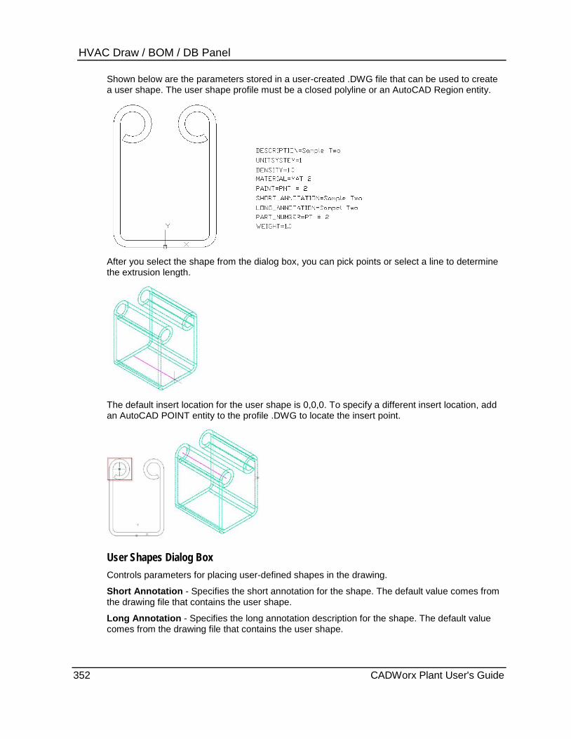
HVAC Draw / BOM / DB Panel Shown below are the parameters stored in a user-created .DWG file that can be used to create a user shape. The user shape profile must be a closed polyline or an AutoCAD Region entity.
After you select the shape from the dialog box, you can pick points or select a line to determine the extrusion length.
The default insert location for the user shape is 0,0,0. To specify a different insert location, add an AutoCAD POINT entity to the profile .DWG to locate the insert point.
User Shapes Dialog Box Controls parameters for placing user-defined shapes in the drawing.
Short Annotation - Specifies the short annotation for the shape. The default value comes from the drawing file that contains the user shape.
Long Annotation - Specifies the long annotation description for the shape. The default value comes from the drawing file that contains the user shape.
352 CADWorx Plant User's Guide
HVAC Draw / BOM / DB Panel Description - Specifies the description for the shape. The default value comes from the drawing file that contains the user shape.
Part Number - Specifies the part number for the shape. The default value comes from the drawing file that contains the user shape.
Material - Specifies the material for the shape. The default value comes from the drawing file that contains the user shape.
Length - Specifies the length of the shape.
Weight - Specifies the weight of the shape.
Roll Angle - Specifies the roll angle about the placement line for the shape. Do not use AutoCAD commands (ROTATE, MIRROR, 3DROTATE) to change the roll angle of the shape. The roll angle of the shape can only be set from the User Shapes dialog box.
Pick points - Places the shape between two points that you identify in the drawing.
Select line - Places the square straight or oval straight shape along an existing polyline in the drawing. This option is disabled for all other shapes.
Component Edit Dialog Box Controls parameters for modifying user-defined shapes in the drawing.
Short Annotation - Specifies the short annotation for the shape. The default value comes from the drawing file that contains the user shape.
Long Annotation - Specifies the long annotation description for the shape. The default value comes from the drawing file that contains the user shape.
Description - Specifies the description for the shape. The default value comes from the drawing file that contains the user shape.
Part Number - Specifies the part number for the shape. The default value comes from the drawing file that contains the user shape.
Material - Specifies the material for the shape. The default value comes from the drawing file that contains the user shape.
Length - Specifies the length of the shape.
Weight - Specifies the weight of the shape.
Roll Angle - Specifies the roll angle about the placement line for the shape.
Manual Update - Indicates that the software uses the manual override value rather than the value from the drawing.
Pick points - Places the shape between two points that you identify in the drawing.
Select line - Places the square straight or oval straight shape along an existing polyline in the drawing. This option is disabled for all other shapes.
What do you want to do? Place a user-defined HVAC shape (on page 354)
Modify a user-defined HVAC shape (on page 354)
CADWorx Plant User's Guide 353

HVAC Draw / BOM / DB Panel
Place a user-defined HVAC shape 1. Click User Shape . Alternatively, type HUSER on the command line, and press ENTER.
The HVAC User Shapes dialog box displays.
2. Select the folder that contains the Type.INI data file to use from the Select Directory list.
The software populates the Select Member list with the available shapes.
3. Select the shape to use from the Select Member list.
The preview and details for that shape display in the Details boxes.
4. Set up the shape parameters to meet your requirements. For more information, see User Shape (on page 351).
5. Click Pick points.
6. Select the first point for the shape.
7. Select the end point for the shape.
The software places the shape in the drawing.
Modify a user-defined HVAC shape 1. Double-click an HVAC shape in the drawing.
The Component Edit dialog box displays the parameters associated with the shape.
2. Change the parameters to meet your requirements. For more information, see User Shape (on page 351).
3. Click Apply.
The software changes the parameters of the shape.
Generic Attach CADWorx Steel / HVAC tab: HVAC Draw / BOM / DB > Generic Attach
Command line: HGENERIC
Attaches information to any generic AutoCAD object in the drawing. You can use the information later in bill of material extraction, labeling, and so forth. After manually constructing a component, use this routine to attach xdata information.
You cannot attach information to a CADWorx object or component.
To pinpoint the center of gravity locations use the Osnap commands. For example, to place information on a beam and have it correctly reflect the center of gravity, draw a centerline and pick MIDpoint, NEArest to the end of the centerline, or the exact location.
354 CADWorx Plant User's Guide
HVAC Draw / BOM / DB Panel Generic Attach (Create/Edit) Dialog Box Controls parameters for attaching information to generic AutoCAD objects.
Long Annotation - Specifies the long annotation for the component, such as W6X25.
Description - Specifies the description for the component, such as Wide Flange.
Short Annotation - Specifies the short annotation for the component, such as W6.
Part number - Specifies the part number for the component, such as 12345.
Material - Specifies the material for the component, such as ASTM A-36.
Length - Specifies the length of the component. Any real number is valid.
Weight - Specifies the weight of the component. Any real number is valid.
BOM Mark Point - Shows the drawing coordinate location at which the information was attached.
Specify On-screen - Click the location in the model view to specify the bill of material mark point.
X - Specifies the X-location for the bill of material mark point. This value defaults to zero.
Y - Specifies the Y-location for the bill of material mark point. This value defaults to zero.
Z - Specifies the Z-location for the bill of material mark point. This value defaults to zero.
CG Location - Shows the center of gravity location at which the information was attached.
Specify On-screen - Click the location in the model view to specify the generic attach center of gravity point.
X - Specifies the X-location for the generic attach center of gravity location. This value defaults to zero.
Y - Specifies the Y-location for the generic attach center of gravity location. This value defaults to zero.
Z - Specifies the Z-location for the generic attach center of gravity location. This value defaults to zero.
What do you want to do? Place a generic attachment in the drawing (on page 355)
Modify a generic attachment
Place a generic attachment in the drawing 1. Click Generic Attach . Alternatively, type HGENERIC on the command line, and press
ENTER.
The Generic Attach (Create) dialog box displays.
2. Set up the attachment parameters to meet your requirements. For more information, see Generic Attach (on page 354).
3. Click Attach.
4. Select the non CADWorx object to which to attach the information.
CADWorx Plant User's Guide 355

HVAC Draw / BOM / DB Panel Specify the Bill of Material Mark Point and the Center of Gravity Location 1. Double-click the entity.
The Generic Attach (Edit) dialog box displays. 2. Click Specify On-screen under BOM Mark Point. 3. Select a point on the object to specify the mark point.
A red arrow displays indicating the point. 4. Click Specify On-screen under CG Location. 5. Select a point on the object to specify the mark point.
A green arrow displays indicating the location. 6. Click OK.
Edit CADWorx Steel / HVAC tab: HVAC Draw / BOM / DB > Edit
Command line: HCEDIT
Edits HVAC or cable tray shapes. This command displays the same dialog box that was used to place the shape. You cannot change the object shape using this command. For more information, see HVAC (on page 346).
GC Edit CADWorx Steel / HVAC tab: HVAC Draw / BOM / DB > GC Edit
Command line: HGCEDIT
Edits global HVAC component data.
HVAC Global CEdit Dialog Box Controls parameters for editing global HVAC component data.
Thickness - Specifies the thickness of the shape wall. This value is required when the Inside dimensions box is selected or the shape is Hollow or Open top. Alter solid - Specifies whether the way the components are drawn can be changed. Solid - Indicates that the software draws the shape as a solid. This is the default setting. Hollow - Indicates that the software draws the shape as hollow.
Open top - Indicates that the software draws the shape with the top open. You cannot use this option with oval shapes.
Open Bottom - Indicates that the software draws the shape with the bottom open. You cannot use this option with oval shapes.
Creating a large number of HVAC shapes with the Hollow or Open top options in a single drawing can significantly increase the drawing size.
Long annotation - Specifies the long annotation description for the shape.
Part number - Specifies the part number for the shape.
Tag - Specifies the tag description for the shape.
Weight - Specifies the weight of the shape.
There is no automatic method for creating long annotation, part number, tag, or weight.
356 CADWorx Plant User's Guide

HVAC Draw / BOM / DB Panel
Edit HVAC components globally 1. Click GCEdit . Alternatively, type HGCEDIT on the command line, and press ENTER.
2. Select the objects to edit, and press ENTER.
The HVAC Global CEdit dialog box displays.
3. Set up the parameters to meet your requirements. For more information, see GC Edit (on page 356).
4. Click OK.
The software applies the parameters to the selected components.
HVAC BOM Setup CADWorx Steel / HVAC tab: HVAC Draw / BOM / DB > Setup
Plant menu: HVAC > Bill of Material > Setup
Command line: HBOMSETUP
Customizes the Bill of Material schedule to any style or layout that you need. Using this dialog box, you can specify column widths, provide the schedule direction (up or down), provide user-specified headings for columns, allow alignment of columns, and the selection of different entries into the schedule. You can arrange the columns in any order.
Table Setup Tab Defines or edits the Bill of Material (BOM) schedule template. The template is stored in the configuration file listed at the top of the dialog.
BOM Columns Available - Lists all the information on a HVAC component that you can include in the BOM. These columns can be added to any schedule template in any order using Add.
BOM Columns Selected - Shows all the columns that have been selected and their order of appearance in the schedule from left (top of list box) to right (bottom of list box). Use Sort Order to set the order by which these columns are sorted.
Add and Remove - Moves selected columns between the BOM Columns Available and BOM Columns Selected lists.
Alignment - Specifies the text alignment for the selected column.
Grow Direction - Specifies whether the schedule should start at the top and work its way down or start at the bottom and work its way up.
Move Up and Move Down - Defines the column order in the BOM. Select a column in the BOM Columns Selected list, and then click Move Up to place the column further left in the BOM. Click Move Down to place the selected column further right in the BOM.
Move Up and Move Down do not set the sort order of the BOM, only the placement of the columns. Use Sort Order Setup tab to define the sort order.
Column title - Specifies the text heading for the selected column.
Column width - Specifies the width for the selected column.
CADWorx Plant User's Guide 357
HVAC Draw / BOM / DB Panel Sort Order Setup Tab Defines or edits the Bill of Material (BOM) schedule template. The template is stored in the configuration file listed at the top of the dialog.
BOM Columns Available - Lists all the information on a HVAC component that you can include in the BOM. These columns can be added to any schedule template in any order using Add.
BOM Columns Selected - Shows all the columns that have been selected and their order of appearance in the schedule from left (top of list box) to right (bottom of list box). Use Sort Order to set the order by which these columns are sorted.
Add and Remove - Moves selected columns between the BOM Columns Available and BOM Columns Selected lists.
Alignment - Specifies the text alignment for the selected column.
Grow Direction - Specifies whether the schedule should start at the top and work its way down or start at the bottom and work its way up.
Move Up and Move Down - Defines the column order in the BOM. Select a column in the BOM Columns Selected list, and then click Move Up to place the column further left in the BOM. Click Move Down to place the selected column further right in the BOM.
Move Up and Move Down do not set the sort order of the BOM, only the placement of the columns. Use Sort Order Setup tab to define the sort order.
Column title - Specifies the text heading for the selected column.
Column width - Specifies the width for the selected column.
What do you want to do? Add or remove properties from BOM (on page 358)
Change the column order (on page 359)
Change text alignment in columns (on page 359)
Change the BOM sorting and accumulation (on page 359)
Add or remove properties from BOM 1. On the HVAC Draw / BOM / DB panel, click Setup . Alternatively, type HBOMSETUP in
the command line, and press ENTER.
The HVAC Bill of Material Setup dialog box displays.
2. To add a property to the BOM, select the property in the BOM Columns Available list, and then click Add.
Use the Column title and Column width boxes to define the column heading text and the column width respectively.
3. To remove a property from the BOM, select the property in the BOM Columns Selected list, and then click Remove.
4. Click OK.
358 CADWorx Plant User's Guide

HVAC Draw / BOM / DB Panel
Change the column order 1. On the HVAC Draw / BOM / DB panel, click Setup . Alternatively, type HBOMSETUP in
the command line, and press ENTER.
The HVAC Bill of Material Setup dialog box displays.
2. Select the column to move in the BOM Columns Selected list.
3. Use Move Up and Move Down to change the column order. The column order in the list top to bottom is the column order in the BOM from left to right.
4. Click OK.
Change text alignment in columns 1. On the HVAC Draw / BOM / DB panel, click Setup . Alternatively, type HBOMSETUP in
the command line, and press ENTER.
The HVAC Bill of Material Setup dialog box displays.
2. Select the column to edit in the BOM Columns Selected list.
3. Select Left, Center, or Right to control the vertical text justification in the selected column.
4. Select Downward or Upward to control the horizontal alignment of the text in the selected column.
5. Click OK.
Change the BOM sorting and accumulation 1. On the HVAC Draw / BOM / DB panel, click Setup . Alternatively, type HBOMSETUP in
the command line, and press ENTER.
The HVAC Bill of Material Setup dialog box displays.
2. Select the Sort Order Setup tab.
3. Move the columns that you want to sort with to the BOM Columns Selected list.
4. Use Move Up and Move Down to specify which columns are sorted first in the BOM.
5. Select a column and use the Ascending and Descending options to control how information in that column is sorted. Ascending means sorting from small numbers to larger numbers (1 to 100) and from A to Z. Descending is large number to smaller (100 to 1) and Z to A.
6. Click OK.
CADWorx Plant User's Guide 359

HVAC Draw / BOM / DB Panel
Cut HVAC Bill of Material CADWorx Steel / HVAC tab: HVAC Draw / BOM / DB > Cut
Plant menu: HVAC > Bill of Material > Run > Cut
Command line: HBOMCUT
Generates a Bill of Material schedule listing each HVAC component with a length and a tag.
Counter - Select this option to start the tag counter at any positive nonzero integer. When set, the command resumes requesting that you pick Manual placement or Automatic placement of tags.
Manual placement - Select to insert tags manually. You are prompted for the tag location. The software adds a rubber band line attached to the component extending to the specified tag location. You must continue specifying locations until the last component’s tag has been placed.
Automatic placement - Select to have CADWorx insert tags automatically. In model space, CADWorx places the tag in the direction (tag to component) provided. In paper space, this prompt does not appear if the tag optimization is on. For more information, see BomTagOptimize (on page 35).
The schedule's text size is based on the AutoCAD setvar TEXTSIZE. If this text size is larger than the schedule spacing, the following message appears and the Bill of Material generation stops. The schedule spacing is controlled by the BomScheduleSpacing (on page 34) variable in the Configuration Settings.
A common mistake in AutoCAD is to apply a text height while setting up a text style. If the
height is specified in the text style dialog, then there is no other way of controlling the size. The text size is set to the size in the dialog regardless of what the TEXTSIZE variable is set to.
CADWorx performs special optimization for automatic tag placement while in paper space only. This optimization places tags in non-overlapping positions and is controlled by the BomTagOptimize variable in the current configuration settings. For more information regarding this functionality and its controls, see BomTagOptimize (on page 35).
What do you want to do? Cut BOM using Automatic placement (on page 361)
Cut BOM using Manual placement (on page 361)
360 CADWorx Plant User's Guide

HVAC Draw / BOM / DB Panel
Cut BOM using Automatic placement 1. On the HVAC Draw / BOM / DB panel, click Cut . Alternatively, type HBOMCUT in the
command line, and press ENTER.
2. Select the Automatic placement option.
3. Type the placement angle for the tag, and press ENTER.
4. Specify a point in the drawing for the upper right corner of the BOM schedule.
5. Select the HVAC components to include in the BOM. Right-click or press ENTER when you are finished.
The BOM is generated.
Cut BOM using Manual placement 1. On the HVAC Draw / BOM / DB panel, click Cut . Alternatively, type HBOMCUT in the
command line, and press ENTER.
2. Select the Manual placement option.
3. Specify a point in the drawing for the upper right corner of the BOM schedule.
4. Select the HVAC components to include in the BOM. Right-click or press ENTER when you are finished.
5. Specify the tag location for each component you selected.
The BOM is generated.
Total HVAC Bill of Material CADWorx Steel / HVAC tab: HVAC Draw / BOM / DB > Total
Plant menu: HVAC > Bill of Material > Run > Total
Command line: HBOMTOTAL
Generates a Bill of Material schedule with one tag for a total length of HVAC components in each size. Identical long annotation items are accumulated in the length column.
Counter - Select this option to start the tag counter at any positive nonzero integer. When set, the command resumes requesting that you pick Manual placement or Automatic placement of tags.
Manual placement - Select to insert tags manually. You are prompted for the tag location. The software adds a rubber band line attached to the component extending to the specified tag location. You must continue specifying locations until the last component’s tag has been placed.
Automatic placement - Select to have CADWorx insert tags automatically. In model space, CADWorx places the tag in the direction (tag to component) provided. In paper space, this prompt does not appear if the tag optimization is on. For more information, see BomTagOptimize (on page 35).
CADWorx Plant User's Guide 361
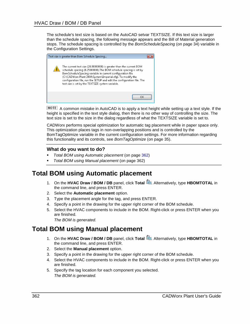
HVAC Draw / BOM / DB Panel The schedule's text size is based on the AutoCAD setvar TEXTSIZE. If this text size is larger than the schedule spacing, the following message appears and the Bill of Material generation stops. The schedule spacing is controlled by the BomScheduleSpacing (on page 34) variable in the Configuration Settings.
A common mistake in AutoCAD is to apply a text height while setting up a text style. If the
height is specified in the text style dialog, then there is no other way of controlling the size. The text size is set to the size in the dialog regardless of what the TEXTSIZE variable is set to.
CADWorx performs special optimization for automatic tag placement while in paper space only. This optimization places tags in non-overlapping positions and is controlled by the BomTagOptimize variable in the current configuration settings. For more information regarding this functionality and its controls, see BomTagOptimize (on page 35).
What do you want to do? Total BOM using Automatic placement (on page 362) Total BOM using Manual placement (on page 362)
Total BOM using Automatic placement 1. On the HVAC Draw / BOM / DB panel, click Total . Alternatively, type HBOMTOTAL in
the command line, and press ENTER. 2. Select the Automatic placement option. 3. Type the placement angle for the tag, and press ENTER. 4. Specify a point in the drawing for the upper right corner of the BOM schedule. 5. Select the HVAC components to include in the BOM. Right-click or press ENTER when you
are finished. The BOM is generated.
Total BOM using Manual placement 1. On the HVAC Draw / BOM / DB panel, click Total . Alternatively, type HBOMTOTAL in
the command line, and press ENTER. 2. Select the Manual placement option. 3. Specify a point in the drawing for the upper right corner of the BOM schedule. 4. Select the HVAC components to include in the BOM. Right-click or press ENTER when you
are finished. 5. Specify the tag location for each component you selected.
The BOM is generated.
362 CADWorx Plant User's Guide
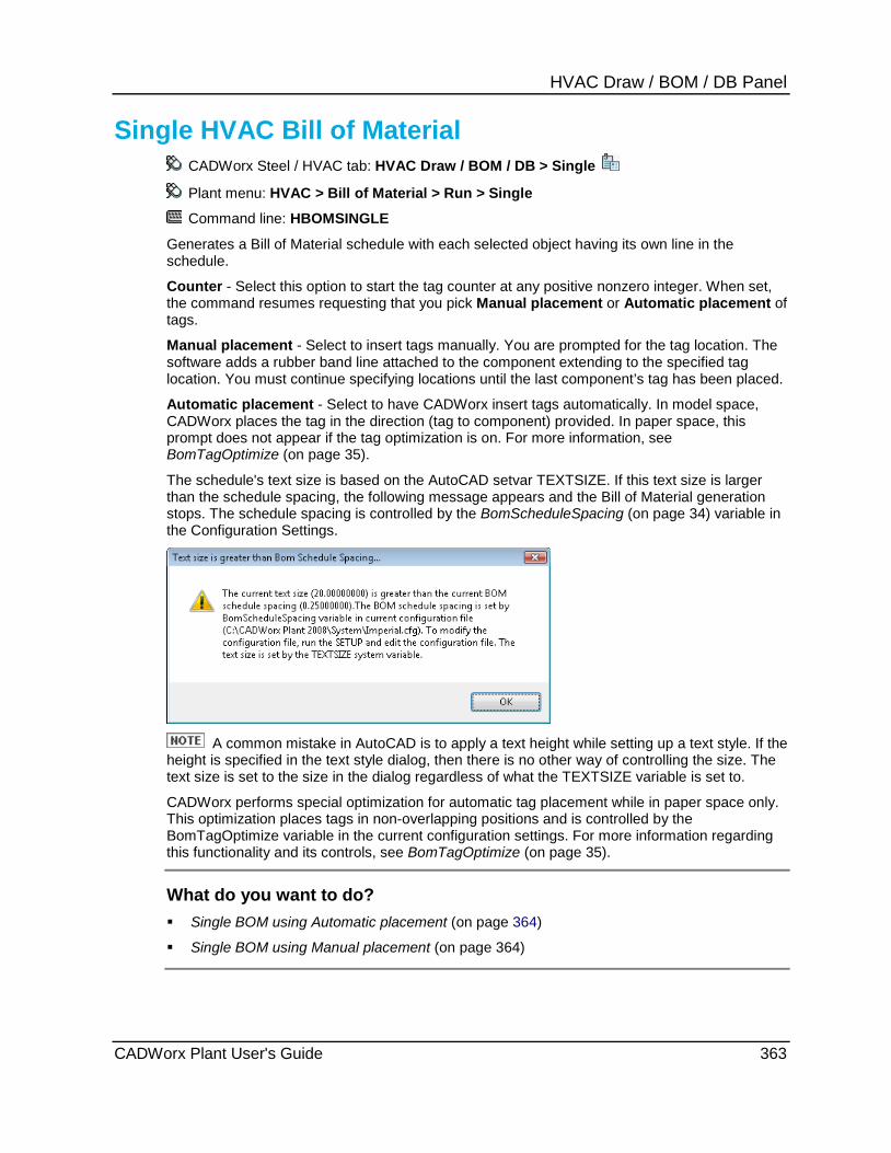
HVAC Draw / BOM / DB Panel
Single HVAC Bill of Material CADWorx Steel / HVAC tab: HVAC Draw / BOM / DB > Single
Plant menu: HVAC > Bill of Material > Run > Single
Command line: HBOMSINGLE
Generates a Bill of Material schedule with each selected object having its own line in the schedule.
Counter - Select this option to start the tag counter at any positive nonzero integer. When set, the command resumes requesting that you pick Manual placement or Automatic placement of tags.
Manual placement - Select to insert tags manually. You are prompted for the tag location. The software adds a rubber band line attached to the component extending to the specified tag location. You must continue specifying locations until the last component’s tag has been placed.
Automatic placement - Select to have CADWorx insert tags automatically. In model space, CADWorx places the tag in the direction (tag to component) provided. In paper space, this prompt does not appear if the tag optimization is on. For more information, see BomTagOptimize (on page 35).
The schedule's text size is based on the AutoCAD setvar TEXTSIZE. If this text size is larger than the schedule spacing, the following message appears and the Bill of Material generation stops. The schedule spacing is controlled by the BomScheduleSpacing (on page 34) variable in the Configuration Settings.
A common mistake in AutoCAD is to apply a text height while setting up a text style. If the
height is specified in the text style dialog, then there is no other way of controlling the size. The text size is set to the size in the dialog regardless of what the TEXTSIZE variable is set to.
CADWorx performs special optimization for automatic tag placement while in paper space only. This optimization places tags in non-overlapping positions and is controlled by the BomTagOptimize variable in the current configuration settings. For more information regarding this functionality and its controls, see BomTagOptimize (on page 35).
What do you want to do? Single BOM using Automatic placement (on page 364)
Single BOM using Manual placement (on page 364)
CADWorx Plant User's Guide 363
HVAC Draw / BOM / DB Panel
Single BOM using Automatic placement 1. On the HVAC Draw / BOM / DB panel, click Single . Alternatively, type HBOMSINGLE
in the command line, and press ENTER.
2. Select the Automatic placement option.
3. Type the placement angle for the tag, and press ENTER.
4. Specify a point in the drawing for the upper right corner of the BOM schedule.
5. Select the HVAC components to include in the BOM. Right-click or press ENTER when you are finished.
The BOM is generated.
Single BOM using Manual placement 1. On the HVAC Draw / BOM / DB panel, click Single . Alternatively, type HBOMSINGLE
in the command line, and press ENTER.
2. Select the Manual placement option.
3. Specify a point in the drawing for the upper right corner of the BOM schedule.
4. Select the HVAC components to include in the BOM. Right-click or press ENTER when you are finished.
5. Specify the tag location for each component you selected.
The BOM is generated.
Data Remove CADWorx Steel / HVAC tab: HVAC Draw / BOM / DB > Data Remove
Command line: HCDATAREMOVE
Removes CADWorx data from components.
Remove CADWorx data from components 1. On the HVAC Draw / BOM / DB panel, click Data Remove . Alternatively, type
HDATAREMOVE in the command line, and press ENTER.
2. Select the objects from which to remove the CADWorx data, and press ENTER.
A dialog box displays asking if you are sure that you want to remove the data.
3. Click Yes.
The software removes the CADWorx data from the selected components.
Layer Change CADWorx Steel / HVAC tab: HVAC Draw / BOM / DB > Layer Change
Command line: HLAYERCHANGE
Changes the solid and centerline layers associated with components.
364 CADWorx Plant User's Guide
HVAC Draw / BOM / DB Panel
Change the layers associated with HVAC components 1. On the HVAC Draw / BOM / DB panel, click Layer Change . Alternatively, type
HLAYERCHANGE in the command line, and press ENTER.
2. Select the objects to change, and press ENTER.
3. If you want to change the solid layer, type Y in the command line, or select Yes from the popup menu.
The Please select Layer dialog box displays.
4. Select the layer with which to associate the solid part of the component, and click OK.
5. If you want to change the centerline layer, type Y in the command line, or select Yes from the popup menu.
The Please select Layer dialog box displays.
6. Select the layer with which to associate the centerline of the component, and click OK.
The software changes the layers.
DB Generate CADWorx Steel / HVAC tab: HVAC Draw / BOM / DB > DB Generate
Command line: HDBFGEN
Exports CADWorx HVAC information to a Microsoft Access or Microsoft Excel file.
Select Database Type Dialog Box Controls parameters for exporting CADWorx HVAC component information.
Database Type - Select Access to write to a Microsoft Access file, or select Excel to write to a Microsoft Excel file.
Browse - Click to define the file name and folder location. The disabled boxes at the bottom of the dialog display the file name and directory in use.
Append/Sync - Synchronizes the drawing and the database file by removing entries from the database that no longer exist in the drawing and updating components in the database according to the drawing. You can use this command once a day or five times an hour to maintain the database according to the drawing. Many users can append to the same database file at the same time.
New - Creates a new database file based on the chosen folder and database type.
Directory - Displays the location of the database file.
Access File - Displays the name of the database file.
Excel File - Displays the name of the database file.
CADWorx Plant User's Guide 365

HVAC Draw / BOM / DB Panel
Export CADWorx HVAC data 1. On the HVAC Draw / BOM / DB panel, click DB Generate . Alternatively, type
HDBFGEN in the command line, and press ENTER.
2. Select the HVAC components to write to the database file. Right-click or press ENTER when you are finished.
The Select Database Type dialog box displays.
3. Select Access or Excel to define the file type.
4. Click Browse, and define the folder and file name.
5. Select New if you are creating a new file.
or
Select Append/Sync if you want to synchronize an existing file.
6. Click OK.
DB In CADWorx Steel / HVAC tab: HVAC Draw / BOM / DB > DB In
Command line: HDBFIN
Imports and draws CADWorx HVAC components from a Microsoft Access or Microsoft Excel file. This command is not available when you are using a live database.
Use the DB Generate (on page 365) command to create the Microsoft Access or Microsoft Excel file to import.
Import CADWorx HVAC data 1. On the HVAC Draw / BOM / DB panel, click DB In . Alternatively, type HDBFIN in the
command line, and press ENTER.
The Select Database File dialog box displays.
2. Select the file to import.
3. Click Open.
The records dialog box displays.
4. Select the drawings in the file to import into the active drawing.
5. Click OK.
Audit HVAC Database CADWorx Steel / HVAC tab: HVAC Draw / BOM / DB > Audit
Command line: HDBAUDIT
Maintains the database for each component in the drawing that has data attached. Use this command whenever the drawing or the database has any problems. If a problem is found in the drawing, for example a component in the database is not present in the drawing, you have the option to delete this component in the database or to ignore it.
366 CADWorx Plant User's Guide
HVAC Draw / BOM / DB Panel
Audit the HVAC database 1. On the HVAC Draw / BOM / DB panel, click Audit . Alternatively, type HDBAUDIT in the
command line, and press ENTER.
The Select Database File dialog box displays.
2. Select the file to audit against the drawing.
3. Click Open.
Checking objects in this drawing with rows in the database.
4. If no problems are found, the message Audit completed displays.
5. If a problem is found, you are prompted to delete the row from the database. Select Yes to delete the row. Select No to ignore the row.
Synchronize HVAC Database CADWorx Steel / HVAC tab: HVAC Draw / BOM / DB > Synchronize
Command line: HSYNC
Checks all components in the drawing and updates them according to the current value in the database. This command does not write new records to the database for new components that are in the model but are not in the database.
When a drawing has a live database attached, you can open the database and edit the SHORT_ANNOTATION, LONG_ANNOTATION, DESCRIPTION, PART_NUMBER, and MATERIAL fields in the HVAC table. Changing any other column value does not have any effect on the drawing.
Synchronize the HVAC database 1. On the HVAC Draw / BOM / DB panel, click Synchronize . Alternatively, type HSYNC in
the command line, and press ENTER.
2. Click Yes to confirm that you want to synchronize the drawing with the database.
CADWorx Plant User's Guide 367

HVAC Draw / BOM / DB Panel
368 CADWorx Plant User's Guide

S E C T I O N 2 2
In This Section Accessing and Docking the Toolbars ............................................ 369 Aliases and Command Names ...................................................... 370 Connecting to components ............................................................ 370 Compass ........................................................................................ 370 Plane versus Isometrics view modes ............................................ 370 3D Modeling versus 2D Modeling .................................................. 370 Buttweld ......................................................................................... 371 Flanges .......................................................................................... 402 Flgd/BW Valves ............................................................................. 415 Lined .............................................................................................. 428 Fiberglass ...................................................................................... 434 Sanitary .......................................................................................... 452 Victaulic ......................................................................................... 486 Threaded/Socket ........................................................................... 491 Thrd/SW Valves ............................................................................. 524 Gaskets, Etc. ................................................................................. 538 Pipe Ends ...................................................................................... 540 Restraints ....................................................................................... 540 Misc................................................................................................ 541 Operators ....................................................................................... 548 Line Numbers ................................................................................ 548 UCS ............................................................................................... 549 Steel ............................................................................................... 549 Settings .......................................................................................... 551 Palettes .......................................................................................... 553
Accessing and Docking the Toolbars Toolbars duplicate commands available on the CADWorx Plant I and CADWorx Plant II tabs. You may find it useful to open toolbars containing frequently-used commands when screen space for the tab is limited.
To open a Plant toolbar, click Plant > Toolbars, and select the needed toolbar. You can also open an alternate set of toolbars from View tab > Windows panel > Toolbars > PIPEALT, PIPEFLY, or PIPERIB.
To dock a toolbar, drag it to any edge of the window. Press CTRL to drag a toolbar without docking it. You can then drag a toolbar off of the window space.
The AutoCAD Toolbar command opens the Customize User Interface dialog box. You can choose any needed toolbars for AutoCAD or CADWorx Plant.
Toolbars
CADWorx Plant User's Guide 369
Toolbars
Aliases and Command Names Ribbon, toolbar, and menu commands have a command name that you can type in the command line.
A command alias is an abbreviation that you type at the command line instead of typing the entire command name. Command aliases created for Plant are delivered in the [Product Folder]\Plant\Support\Flow_alt.pgp file.
You can change alias names but should avoid conflicts with aliases already defined in the .pgp file for AutoCAD.
Connecting to components In connecting to components, Piping Rules effect the behavior of prompts when set to No or Show Options. If selecting a component from a palette or toolbar, the selected component prompts you if unable to derive information from the surrounding components due to the piping rules. When the rules are set to Automatic, the process is simplified for connecting components to appropriate valued objects. For instance, when inserting a flange to a pipe, if both have the same size and specification you are not prompted and the flange inserts automatically. For more information, see Apply Flange Insertion Rule (on page 51) or all other Piping Rules (on page 49). Prompts depend on the settings you have chosen for the piping rules. Also, you may be prompted in certain situations based on the components of the model. Most of the components are built to work as smart objects. They connect using the previous information of the last point of a component. If you change sizes while working with a component, you are prompted accordingly. In addition, you may not receive prompts based on the actions of connection to components. Prompts depend on the actions you take, and some prompts appear only when not connecting to a previous component.
Compass Enables 360 degree navigation for placement of components. You can turn the compass on and off in Setup (on page 28). You are also provided with the option to change the color. When the compass is turned on the screen displays a circle around the components when they are pulled into the drawing space.
Plane versus Isometrics view modes When plotting components using Plane views, some prompts appear differently when working in 3D Solids then when plotting components in Isometric views. This is based on the directional limitations of those views. The prompts do not differ when you are working in 2D Double Line or 2D Single Line. All commands in the following sections are based off the isometrics view for all modes of modeling.
3D Modeling versus 2D Modeling The CADWorx option for working in 3D modeling and 2D modeling is set up in the CADWorx Plant Setup dialog box. All commands on the toolbars work in both modes, however some commands are ideally designed for working in 3D mode versus working in 2D mode. The commands are grouped according to which commands are better suited for either 3D modeling or 2D modeling. You can use the commands as needed, but in 3D modeling some of the commands better suited for 2D have the same response as those better suited for 3D. For more information, see Setup (on page 28) and CADWorx Plant Setup Dialog Box.
370 CADWorx Plant User's Guide
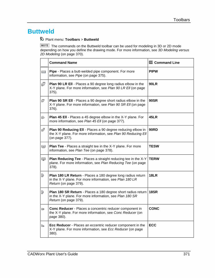
Toolbars
Buttweld Plant menu: Toolbars > Buttweld
The commands on the Buttweld toolbar can be used for modeling in 3D or 2D mode depending on how you define the drawing mode. For more information, see 3D Modeling versus 2D Modeling (on page 370).
Command Name Command Line
Pipe - Places a butt-welded pipe component. For more information, see Pipe (on page 375).
PIPW
Plan 90 LR Ell - Places a 90 degree long radius elbow in the X-Y plane. For more information, see Plan 90 LR Ell (on page 375).
90LR
Plan 90 SR Ell - Places a 90 degree short radius elbow in the X-Y plane. For more information, see Plan 90 SR Ell (on page 376).
90SR
Plan 45 Ell - Places a 45 degree elbow in the X-Y plane. For more information, see Plan 45 Ell (on page 377).
45LR
Plan 90 Reducing Ell - Places a 90 degree reducing elbow in the X-Y plane. For more information, see Plan 90 Reducing Ell (on page 377).
90RD
Plan Tee - Places a straight tee in the X-Y plane. For more information, see Plan Tee (on page 378).
TESW
Plan Reducing Tee - Places a straight reducing tee in the X-Y plane. For more information, see Plan Reducing Tee (on page 378).
TERW
Plan 180 LR Return - Places a 180 degree long radius return in the X-Y plane. For more information, see Plan 180 LR Return (on page 379).
18LR
Plan 180 SR Return - Places a 180 degree short radius return in the X-Y plane. For more information, see Plan 180 SR Return (on page 379).
18SR
Conc Reducer - Places a concentric reducer component in the X-Y plane. For more information, see Conc Reducer (on page 380).
CONC
Ecc Reducer - Places an eccentric reducer component in the X-Y plane. For more information, see Ecc Reducer (on page 380).
ECC
CADWorx Plant User's Guide 371

Toolbars
Command Name Command Line
Cap - Places a pipe cap in the X-Y plane. For more information, see Cap (on page 381).
CAPW
Plan Cross - Places a four-way straight cross in the X-Y plane. For more information, see Plan Cross (on page 381).
CRSW
Plan Reducing Cross - Places a four-way reducing cross in the X-Y plane. For more information, see Plan Reducing Cross (on page 382).
CRRW
Plan Lateral - Places a 45 degree lateral tee in the X-Y plane. For more information, see Plan Lateral (on page 382).
LATW
Miters - Places a mitered pipe component in the X-Y plane. For more information, see Miters (on page 383).
MPIP
Rolled Pipe - Places a free-form pipe component, such as a hose or flexible connection. For more information, see Rolled Pipe (on page 383).
SPIP
Adjustable Bend - Places an adjustable pipe bend. For more information, see Adjustable Bend (on page 384).
BENT
90 LR Ell - Places a 90 degree long radius elbow with the end rolled at a 45 degree angle from the X-Y plane. For more information, see 90 LR Ell (on page 386).
R90LR
90 SR Ell - Places a 90 degree short radius elbow with the end rolled at a 45 degree angle from the X-Y plane. For more information, see 90 SR Ell (on page 387).
R90SR
45 LR Ell - Places a 45 degree elbow with the end rolled at a 45 degree angle from the X-Y plane. For more information, see 45 LR Ell (on page 387).
R45LR
Tee - Places a tee with the branch rolled at a 45 degree angle from the X-Y plane. For more information, see Tee (on page 388).
RTESW
Plan 11.25 Ell - Places an 11.25 degree elbow in the X-Y plane. For more information, see Plan 11.25 Ell (on page 388).
11LR
Plan 22.5 Ell - Places a 22.5 degree elbow in the X-Y plane. For more information, see Plan 22.5 Ell (on page 389).
22LR
Plan Wye - Places a wye in the X-Y plane. For more information, see Plan Wye (on page 389).
YB
372 CADWorx Plant User's Guide

Toolbars The commands in the table below are designed for modeling in 2D.
Command Name Command Line
Side 90 LR Ell - Places a 90 degree long radius elbow normal to the X-Y plane. For more information, see Side 90 LR Ell (on page 390).
H90LR
Side 90 SR Ell - Places a 90 degree short radius elbow normal to the X-Y plane. For more information, see Side 90 SR Ell (on page 391).
H90SR
Side 45 Ell - Places a 45 degree elbow normal to the X-Y plane when the previous or next run is horizontal to the X-Y plane. For more information, see Side 45 Ell (on page 391).
H45LR
Vert 45 Ell - Places a 45 degree elbow normal to the X-Y plane when the previous or next run is vertical to the X-Y plane. For more information, see Vert 45 Ell (on page 392).
V45LR
Side 90 Reducing Ell - Places a 90 degree reducing elbow normal to the X-Y plane. For more information, see Side 90 Reducing Ell (on page 392).
H90RD
Side Tee - Places a straight tee with the branch normal to the X-Y plane. For more information, see Side Tee (on page 393).
HTESW
Vert Tee - Places a straight tee with the main normal to the X-Y plane. For more information, see Vert Tee (on page 393).
VTESW
Side Reducing Tee - Places a straight reducing tee with the branch normal to the X-Y plane. For more information, see Side Reducing Tee (on page 394).
HTERW
Vert Reducing Tee - Places a straight reducing tee with the main normal to the X-Y plane. For more information, see Vert Reducing Tee (on page 394).
VTERW
Side 180 LR Return - Places a 180 degree long radius return normal to the X-Y plane with the return ends on the X-Y plane. For more information, see Side 180 LR Return (on page 395).
H18LR
Vert 180 LR Return - Places a 180 degree long radius return normal to the X-Y plane with the return ends also normal to the X-Y plane. For more information, see Vert 180 LR Return (on page 395).
V18LR
Side 180 SR Return - Places a 180 degree short radius return normal to the X-Y plane with the return ends on the X-Y plane. For more information, see Side 180 SR Return (on page 396).
H18SR
CADWorx Plant User's Guide 373
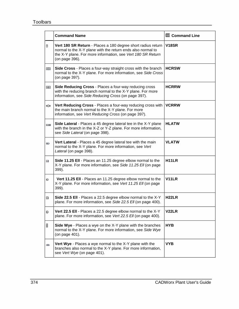
Toolbars
Command Name Command Line
Vert 180 SR Return - Places a 180 degree short radius return normal to the X-Y plane with the return ends also normal to the X-Y plane. For more information, see Vert 180 SR Return (on page 396).
V18SR
Side Cross - Places a four-way straight cross with the branch normal to the X-Y plane. For more information, see Side Cross (on page 397).
HCRSW
Side Reducing Cross - Places a four-way reducing cross with the reducing branch normal to the X-Y plane. For more information, see Side Reducing Cross (on page 397).
HCRRW
Vert Reducing Cross - Places a four-way reducing cross with the main branch normal to the X-Y plane. For more information, see Vert Reducing Cross (on page 397).
VCRRW
Side Lateral - Places a 45 degree lateral tee in the X-Y plane with the branch in the X-Z or Y-Z plane. For more information, see Side Lateral (on page 398).
HLATW
Vert Lateral - Places a 45 degree lateral tee with the main normal to the X-Y plane. For more information, see Vert Lateral (on page 398).
VLATW
Side 11.25 Ell - Places an 11.25 degree elbow normal to the X-Y plane. For more information, see Side 11.25 Ell (on page 399).
H11LR
Vert 11.25 Ell - Places an 11.25 degree elbow normal to the X-Y plane. For more information, see Vert 11.25 Ell (on page 399).
V11LR
Side 22.5 Ell - Places a 22.5 degree elbow normal to the X-Y plane. For more information, see Side 22.5 Ell (on page 400).
H22LR
Vert 22.5 Ell - Places a 22.5 degree elbow normal to the X-Y plane. For more information, see Vert 22.5 Ell (on page 400).
V22LR
Side Wye - Places a wye on the X-Y plane with the branches normal to the X-Y plane. For more information, see Side Wye (on page 401).
HYB
Vert Wye - Places a wye normal to the X-Y plane with the branches also normal to the X-Y plane. For more information, see Vert Wye (on page 401).
VYB
374 CADWorx Plant User's Guide

Toolbars
Modeling in 3D These commands are useful for 3D modeling. All of the following commands are available in 3D and 2D modeling.
Pipe Buttweld toolbar: Pipe
Sanitary toolbar: Sanitary Tubing
Victaulic toolbar: Victaulic Pipe
Command line: PIPW
You can also now use PIPW1 for buttweld piping, PIPF1 for socket weld or threaded piping, and PIPFL1 for flanged piping, to draw singular pipe. PIPW starts the pipe router.
Places a pipe component in the X-Y plane.
last point - Starts the pipe at the last point of the previously-created component.
Center - Places the pipe along the center of the pipe, as defined along the Z-axis.
TOP - Places the pipe along the top of the pipe, as defined along the Z-axis.
BOP - Places the pipe along the bottom of the pipe, as defined along the Z-axis.
Right - Places the pipe along the right side of the pipe, as defined along the Z-axis
Left - Places the pipe along the left side of the pipe, as defined along the Z-axis
Place a pipe 1. Click a pipe component command.
2. Click to select a starting point, or type coordinates in the command line and press ENTER.
3. Click to select an ending point, or type coordinates in the command line and press ENTER.
The pipe component is drawn.
Plan 90 LR Ell Buttweld toolbar: Plan 90 LR Ell
Victaulic toolbar: Plan 90 LR Ell
Command line: 90LR
Places a 90 degree long radius elbow in the X-Y plane.
last point - Starts the component at the last point of the previously-created component.
Start - Places the component anywhere in the drawing at any chosen start point.
Corner - Places the component at the corner of two pipes.
otherEnd - Places the start point of the component on the other end.
CADWorx Plant User's Guide 375
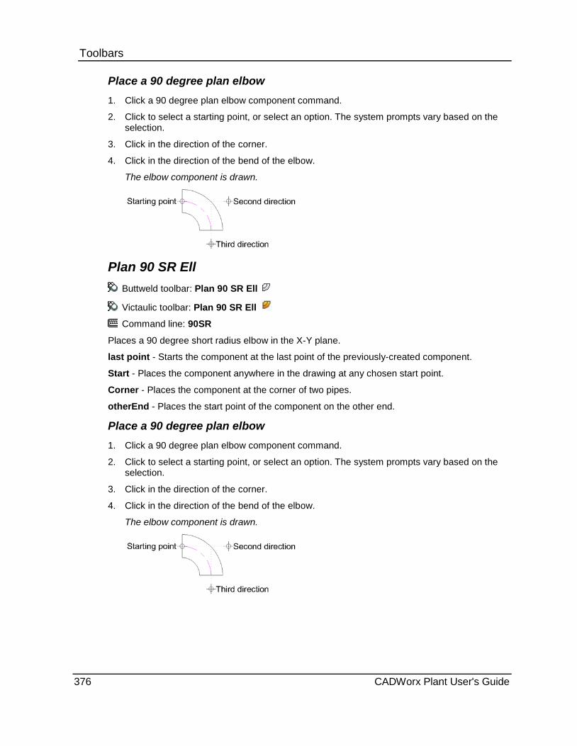
Toolbars Place a 90 degree plan elbow 1. Click a 90 degree plan elbow component command.
2. Click to select a starting point, or select an option. The system prompts vary based on the selection.
3. Click in the direction of the corner.
4. Click in the direction of the bend of the elbow.
The elbow component is drawn.
Plan 90 SR Ell Buttweld toolbar: Plan 90 SR Ell
Victaulic toolbar: Plan 90 SR Ell
Command line: 90SR
Places a 90 degree short radius elbow in the X-Y plane.
last point - Starts the component at the last point of the previously-created component.
Start - Places the component anywhere in the drawing at any chosen start point.
Corner - Places the component at the corner of two pipes.
otherEnd - Places the start point of the component on the other end.
Place a 90 degree plan elbow 1. Click a 90 degree plan elbow component command.
2. Click to select a starting point, or select an option. The system prompts vary based on the selection.
3. Click in the direction of the corner.
4. Click in the direction of the bend of the elbow.
The elbow component is drawn.
376 CADWorx Plant User's Guide

Toolbars Plan 45 Ell
Buttweld toolbar: Plan 45 Ell Victaulic toolbar: Plan 45 Ell Command line: 45LR
Places a 45 degree elbow in the X-Y plane. last point - Starts the component at the last point of the previously-created component. Start - Places the component anywhere in the drawing at any chosen start point. Corner - Places the component at the corner of two pipes. otherEnd - Places the start point of the component on the other end. Place a plan elbow 1. Click a plan elbow command. 2. Pick a starting point, such as at the end of a pipe. 3. Click in the direction of the corner. 4. Click in the direction of the bend of the elbow.
The elbow component is drawn.
Plan 90 Reducing Ell Buttweld toolbar: Plan 90 Reducing Ell Victaulic toolbar: Plan 90 Reducing Ell Command line: 90RD
Places a 90 degree reducing elbow in the X-Y plane. last point - Starts the component at the last point of the previously-created component. Corner - Places the component at the corner of two pipes. otherEnd - Places the start point of the component on the other end. For this component, this option switches to the reducing side.
Place a 90 degree reducing plan elbow 1. Click a 90 degree reducing plan elbow component command. 2. To optionally place the reducing end first, right-click and select otherEnd. 3. Pick a starting point, such as at the end of a pipe. 4. Click in the direction of the corner. 5. Click in the direction of the bend of the elbow.
The elbow component is drawn.
CADWorx Plant User's Guide 377

Toolbars Plan Tee
Buttweld toolbar: Plan Tee
Victaulic toolbar: Plan Tee
Command line: TESW
Places a straight tee in the X-Y plane.
last point - Starts the component at the last point of the previously-created component.
Branch - Places the branch of the tee at the start point.
Middle - Places the tee at the centerline intersection of the branch and main of the tee.
Place a plan tee 1. Click a plan tee command. 2. Click to select a starting point, such as at the end of a pipe. 3. Click in the direction of the main of the tee. 4. Click in the direction of the branch of the tee.
The tee component is drawn.
Plan Reducing Tee Buttweld toolbar: Plan Reducing Tee Victaulic toolbar: Plan Reducing Tee Command line: TERW
Places a straight reducing tee in the X-Y plane. last point - Starts the component at the last point of the previously-created component. Branch - Places the branch of the tee at the start point. Middle - Places the tee at the centerline intersection of the branch and main of the tee.
Place a plan tee 1. Click a plan tee command. 2. Click to select a starting point, such as at the end of a pipe. 3. Click in the direction of the main of the tee. 4. Click in the direction of the branch of the tee.
The tee component is drawn.
378 CADWorx Plant User's Guide

Toolbars Plan 180 LR Return
Buttweld toolbar: Plan 180 LR Return
Command line: 18LR
Places a 180 degree long radius return in the X-Y plane. last point - Starts the component at the last point of the previously-created component. Start - Places the component anywhere in the drawing at any chosen start point. Corner - Places the component at the corner of two pipes. otherEnd - Places the start point of the component on the other end. Place a 180 degree plan return 1. Click a 180 degree plan return component command. 2. Click to select a starting point, such as at the end of a pipe. 3. Click in the direction of the bend of the return. 4. Click in the direction of the end of the return.
The return component is drawn.
Plan 180 SR Return Buttweld toolbar: Plan 180 SR Return
Command line: 18SR
Places a 180 degree short radius return in the X-Y plane. last point - Starts the component at the last point of the previously-created component. Start - Places the component anywhere in the drawing at any chosen start point. Corner - Places the component at the corner of two pipes. otherEnd - Places the start point of the component on the other end.
Place a 180 degree plan return 1. Click a 180 degree plan return component command. 2. Click to select a starting point, such as at the end of a pipe. 3. Click in the direction of the bend of the return. 4. Click in the direction of the end of the return.
The return component is drawn.
CADWorx Plant User's Guide 379
Toolbars Conc Reducer
Buttweld toolbar: Conc Reducer
Victaulic toolbar: Conc Reducer
Command line: CONC
Places a concentric reducer component in the X-Y plane.
last point - Starts the component at the last point of the previously-created component.
Large end - Places the non-reducing end at the start point.
Small end - Places the reducing end at the start point.
If you are connecting to another component where the large end is the same size as the last component, press ENTER to attach to the last component drawn.
Place a concentric reducer 1. Click a concentric reducer component command.
2. Pick a starting point for the large end, such as at the end of a pipe.
3. Click in the direction of the small end of the reducer.
The reducer component is drawn.
Ecc Reducer Buttweld toolbar: Ecc Reducer
Victaulic toolbar: Ecc Reducer
Command line: ECC
Places an eccentric reducer component in the X-Y plane.
last point - Starts the component at the last point of the previously-created component.
Large end - Places the non-reducing end at the start point.
Small end - Places the reducing end at the start point.
Up - Places the flat side of the reducer in the positive Z direction.
Down - Places the flat side of the reducer in the negative Z direction.
Place an eccentric reducer 1. Click an eccentric reducer component command. 2. Pick a starting point for the large end, such as at the end of a pipe.
or Select Small end, and press ENTER.
3. Click in the direction of the other end of the reducer. 4. To place the flat side in the X-Y plane, click in the direction of the flat side.
or To place the flat side in the Z direction, select Up or Down. The reducer component is drawn.
380 CADWorx Plant User's Guide

Toolbars Cap
Buttweld toolbar: Cap
Victaulic toolbar: Cap
Command line: CAPW
Places a pipe cap in the X-Y plane.
last point - Starts the component at the last point of the previously-created component.
Cap end - Places the top of the cap at the start point.
Place a cap 1. Click a cap component command.
2. Click to select a starting point, such as the end of a pipe.
3. Click to select the direction of the top of the cap.
The cap component is drawn.
Plan Cross Buttweld toolbar: Plan Cross
Victaulic toolbar: Plan Cross
Command line: CRSW
Places a four-way straight cross in the X-Y plane.
last point - Starts the component at the last point of the previously-created component.
Middle - Places the cross at the centerline intersection of the cross.
Branch - Places the branch of the cross at the start point.
Place a plan cross 1. Click a four-way straight cross command.
2. Click to select a starting point, such as at the end of a pipe.
3. Click in the direction of the cross.
The cross component is drawn.
CADWorx Plant User's Guide 381

Toolbars Plan Reducing Cross
Buttweld toolbar: Plan Reducing Cross
Victaulic toolbar: Plan Reducing Cross
Command line: CRRW
Places a four-way reducing cross in the X-Y plane.
last point - Starts the component at the last point of the previously-created component.
Branch - Places the reducing branch of cross tee at the start point.
Middle - Places the tee at the centerline intersection of the cross.
Place a plan reducing cross 1. Click a four-way plan reducing cross command.
2. Click to select a starting point, such as at the end of a pipe.
3. Click in the direction of the cross.
The cross component is drawn.
Plan Lateral Buttweld toolbar: Plan Lateral Victaulic toolbar: Plan Lateral Command line: LATW
Places a 45 degree lateral in the X-Y plane. last point - Starts the component at the last point of the previously-created component. Middle - Places the lateral at the centerline intersection of the branch and main. Branch - Places the branch of the lateral at the start point. otherEnd - Places the start point of the component on the other end.
Place a plan lateral 1. Click a plan lateral command. 2. Click to select a starting point, such as at the end of a pipe. 3. Click in the direction of the main of the lateral. 4. Click in the direction of the branch of the lateral.
The lateral component is drawn.
382 CADWorx Plant User's Guide

Toolbars Miters
Buttweld toolbar: Miters
Command line: MPIP
Places a mitered pipe component in the X-Y plane. The pipe is placed on a 2D polyline created with Polyline . A miter is placed on the pipe at each vertex of the polyline. For more information, see PLINE in AutoCAD Help.
This command can also be used to create pipe with bends. For more information, see CHAMFER in AutoCAD Help.
Mitered pipe cannot be placed on a 3D polyline created with 3D Polyline . For more information, see 3DPOLY in AutoCAD Help.
Place a mitered pipe 1. On the Draw panel of the Home tab, click Polyline .
2. Draw the needed polyline.
3. Click Miters .
4. Select the polyline.
The mitered pipe component is drawn.
Rolled Pipe Buttweld toolbar: Rolled Pipe
Command line: SPIP
Places a free-form pipe component, such as a hose or flexible connection. The pipe is placed on a 2D polyline created with Polyline and edited with the Fit or Spline options of Edit Polyline . For more information, see PLINE and PEDIT in AutoCAD Help.
CADWorx Plant User's Guide 383

Toolbars Fit Example
Spline Example
Rolled pipe cannot be placed on a 3D polyline created with 3D Polyline . For more
information, see 3DPOLY in AutoCAD Help.
Place a rolled pipe 1. On the Draw panel of the Home tab, click Polyline .
2. Draw the needed polyline.
3. On the Modify panel, click Edit Polyline .
4. Select the polyline.
5. Select Fit or Spline.
6. Click Rolled Pipe .
7. Select the polyline.
The pipe component is drawn.
Adjustable Bend Buttweld toolbar: Adjustable Bend
Command line: BENT
Places a pipe bend based on the selected method: Enter radius, Trimmed elbow, or Select arc.
384 CADWorx Plant User's Guide
Toolbars Enter radius - Places a pipe bend by typing a radius, and then selecting the bend center, start, and end points in a counterclockwise direction. This is the most common type of adjustable bend.
Degree - Defines the total angle of the bend from the start point. For example, if the start point is at 91°, and the value for Degree is 180°, the end point is at 271° and the total angle of the bend is 180°.
Angle - Defines the angle of the bend as the value minus the angle defined by the start point from the positive X-axis. For example, if the start point is at 91°, and the value for Angle is 180°, the end point is at 180° and the angle of the bend is 79°.
Tangent length - Defines straight lengths of pipe at each end of the bend. This is frequently required for machine bending. You can type a value of 0.
Trimmed elbow - Places an elbow by selecting the center of the bend arc, the start point, and the end point.
Short radius - Defines a short radius elbow according to the current specification.
Long radius - Defines a long radius elbow according to the current specification.
Select arc - Places a pipe bend on an arc created with an arc command. For more information, see Draw Arcs in AutoCAD Help.
Tangent length - Defines straight lengths of pipe at each end of the bend. This is frequently required for machine bending. You can type a value of 0.
Place an adjustable bend
Enter Radius 1. Click Adjustable Bend on the Buttweld toolbar in the Miters drop-down. Alternatively,
type BENT on the command line, and then press ENTER.
2. Type a radius on the command line, and then press ENTER.
3. Select a center point.
4. Select a first direction.
5. Select a second direction.
6. Type a Tangent length on the command line, and then press ENTER.
The adjustable bend displays in the drawing.
Select Arc 1. Draw an AutoCAD arc.
2. Click Adjustable Bend on the Buttweld toolbar in the Miters drop-down. Alternatively, type BENT on the command line, and then press ENTER.
3. Click Select Arc.
4. Select the arc in the drawing.
5. Type a Tangent length on the command line, and then press ENTER.
The adjustable bend displays in the drawing.
CADWorx Plant User's Guide 385

Toolbars Trimmed Elbow 1. Click Adjustable Bend on the Buttweld toolbar in the Miters drop-down. Alternatively,
type BENT on the command line, and then press ENTER.
2. Select Trimmed Elbow.
3. Select a corner point.
4. Select a first direction.
5. Select a second direction.
6. Select Long radius or Short radius.
The adjustable bend displays in the drawing.
90 LR Ell Buttweld toolbar: 90 LR Ell
Command line: R90LR
Places a 90 degree long radius elbow with the end rolled at a 45 degree angle from the X-Y plane.
last point - Starts the component at the last point of the previously-created component.
Start - Places the component anywhere in the drawing at any chosen start point.
Corner - Places the component at the corner of two pipes.
otherEnd - Places the start point of the component on the other end.
Up - Rotates the end of the elbow 45 degrees in the positive Z direction.
Down - Rotates the end of the elbow 45 degrees in the negative Z direction.
This command is only available for welded fittings.
The elbow centerline is out-of-plane. You must use an AutoCAD UCS command to obtain the proper plane before modifying the elbow. For more information, see UCS in AutoCAD Help.
Place a 90 degree rolled elbow 1. Click a 90 degree rolled elbow component command.
2. Click to select a starting point, such as at the end of a pipe.
3. Click in the direction of the corner.
4. Click in the direction of the bend of the elbow.
The elbow component is drawn.
386 CADWorx Plant User's Guide

Toolbars 90 SR Ell
Buttweld toolbar: 90 SR Ell
Command line: R90SR
Places a 90 degree short radius elbow with the end rolled at a 45 degree angle from the X-Y plane.
last point - Starts the component at the last point of the previously-created component.
Start - Places the component anywhere in the drawing at any chosen start point.
Corner - Places the component at the corner of two pipes.
otherEnd - Places the start point of the component on the other end.
Up - Rotates the end of the elbow 45 degrees in the positive Z direction.
Down - Rotates the end of the elbow 45 degrees in the negative Z direction.
This command is only available for welded fittings.
The elbow centerline is out-of-plane. You must use an AutoCAD UCS command to obtain the proper plane before modifying the elbow. For more information, see UCS in AutoCAD Help.
Place a 90 degree rolled elbow 1. Click a 90 degree rolled elbow component command. 2. Click to select a starting point, such as at the end of a pipe. 3. Click in the direction of the corner. 4. Click in the direction of the bend of the elbow.
The elbow component is drawn.
45 LR Ell Buttweld toolbar: 45 LR Ell
Command line: R45LR
Places a 45 degree elbow with the end rolled at a 45 degree angle from the X-Y plane. This command is only available for welded fittings.
last point - Starts the component at the last point of the previously-created component. Start - Places the component anywhere in the drawing at any chosen start point. Corner - Places the component at the corner of two pipes. otherEnd - Places the start point of the component on the other end. Up - Rotates the end of the elbow 45 degrees in the positive Z direction. Down - Rotates the end of the elbow 45 degrees in the negative Z direction.
This command is only available for welded fittings.
The elbow centerline is out-of-plane. You must use an AutoCAD UCS command to obtain the proper plane before modifying the elbow. For more information, see UCS in AutoCAD Help.
CADWorx Plant User's Guide 387

Toolbars Place a 45 degree rolled elbow 1. Click 45 LR Ell .
2. Click to select a starting point, such as at the end of a pipe.
3. Click in the direction of the corner.
4. Click in the direction of the bend of the elbow.
The elbow component is drawn.
Tee Buttweld toolbar: Tee
Command line: RTESW
Places a tee with the branch rolled at a 45 degree angle from the X-Y plane.
Middle - Places the tee at the centerline intersection of the branch and main of the tee.
Up - Rotates the branch of the tee 45 degrees in the positive Z direction.
Down - Rotates the branch of the tee 45 degrees in the negative Z direction.
This command is only available for welded fittings.
Place a rolled tee 1. Click a rolled tee command.
2. Click to select a starting point, such as at the end of a pipe.
3. Click in the direction of the main of the tee.
4. Click in the direction of the branch of the tee.
5. Select Up or Down.
The tee component is drawn.
Plan 11.25 Ell Buttweld toolbar: Plan 11.25 Ell
Victaulic toolbar: Plan 11.25 Ell
Command line: 11LR
Places an 11.25 degree elbow in the X-Y plane.
last point - Starts the component at the last point of the previously-created component.
Corner - Places the component at the corner of two pipes.
otherEnd - Places the start point of the component on the other end.
388 CADWorx Plant User's Guide

Toolbars Place a plan elbow 1. Click a plan elbow command.
2. Pick a starting point, such as at the end of a pipe.
3. Click in the direction of the corner.
4. Click in the direction of the bend of the elbow.
The elbow component is drawn.
Plan 22.5 Ell Buttweld toolbar: Plan 22.5 Ell
Victaulic toolbar: Plan 22.5 Ell
Command line: 22LR
Places a 22.5 degree elbow in the X-Y plane.
last point - Starts the component at the last point of the previously-created component.
Corner - Places the component at the corner of two pipes.
Place a plan elbow 1. Click a plan elbow command.
2. Pick a starting point, such as at the end of a pipe.
3. Click in the direction of the corner.
4. Click in the direction of the bend of the elbow.
The elbow component is drawn.
Plan Wye Buttweld toolbar: Plan Wye
Victaulic toolbar: Plan Wye
Command line: YB
Places a wye in the X-Y plane.
CADWorx Plant User's Guide 389
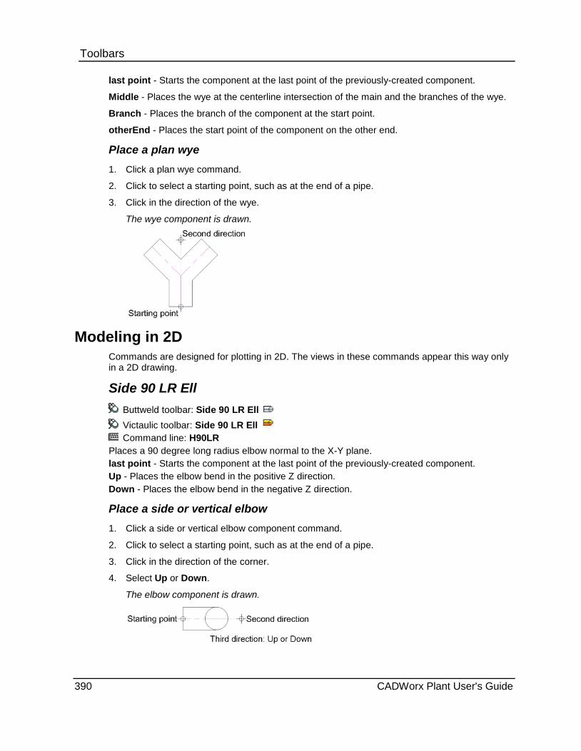
Toolbars last point - Starts the component at the last point of the previously-created component.
Middle - Places the wye at the centerline intersection of the main and the branches of the wye.
Branch - Places the branch of the component at the start point.
otherEnd - Places the start point of the component on the other end.
Place a plan wye 1. Click a plan wye command.
2. Click to select a starting point, such as at the end of a pipe.
3. Click in the direction of the wye.
The wye component is drawn.
Modeling in 2D Commands are designed for plotting in 2D. The views in these commands appear this way only in a 2D drawing.
Side 90 LR Ell Buttweld toolbar: Side 90 LR Ell Victaulic toolbar: Side 90 LR Ell Command line: H90LR
Places a 90 degree long radius elbow normal to the X-Y plane. last point - Starts the component at the last point of the previously-created component. Up - Places the elbow bend in the positive Z direction. Down - Places the elbow bend in the negative Z direction.
Place a side or vertical elbow 1. Click a side or vertical elbow component command.
2. Click to select a starting point, such as at the end of a pipe.
3. Click in the direction of the corner.
4. Select Up or Down.
The elbow component is drawn.
390 CADWorx Plant User's Guide

Toolbars Side 90 SR Ell
Buttweld toolbar: Side 90 SR Ell
Victaulic toolbar: Side 90 SR Ell
Command line: H90SR
Places a 90 degree short radius elbow normal to the X-Y plane.
last point - Starts the component at the last point of the previously-created component.
Up - Places the elbow bend in the positive Z direction.
Down - Places the elbow bend in the negative Z direction.
Place a side or vertical elbow 1. Click a side or vertical elbow component command.
2. Click to select a starting point, such as at the end of a pipe.
3. Click in the direction of the corner.
4. Select Up or Down.
The elbow component is drawn.
Side 45 Ell Buttweld toolbar: Side 45 Ell Victaulic toolbar: Side 45 Ell Command line: H45LR
Places a 45 degree elbow normal to the X-Y plane. Use this command when the previous or next run is horizontal to the X-Y plane. last point - Starts the component at the last point of the previously-created component. Up - Places the elbow bend in the positive Z direction. Down - Places the elbow bend in the negative Z direction.
Place a side or vertical elbow 1. Click a side or vertical elbow component command.
2. Click to select a starting point, such as at the end of a pipe.
3. Click in the direction of the corner.
4. Select Up or Down.
The elbow component is drawn.
CADWorx Plant User's Guide 391
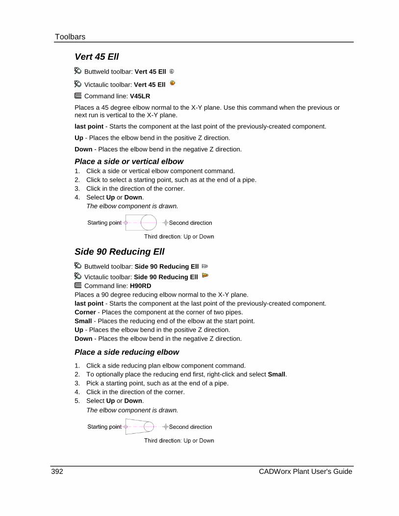
Toolbars Vert 45 Ell
Buttweld toolbar: Vert 45 Ell
Victaulic toolbar: Vert 45 Ell
Command line: V45LR
Places a 45 degree elbow normal to the X-Y plane. Use this command when the previous or next run is vertical to the X-Y plane.
last point - Starts the component at the last point of the previously-created component.
Up - Places the elbow bend in the positive Z direction.
Down - Places the elbow bend in the negative Z direction.
Place a side or vertical elbow 1. Click a side or vertical elbow component command. 2. Click to select a starting point, such as at the end of a pipe. 3. Click in the direction of the corner. 4. Select Up or Down.
The elbow component is drawn.
Side 90 Reducing Ell Buttweld toolbar: Side 90 Reducing Ell Victaulic toolbar: Side 90 Reducing Ell Command line: H90RD
Places a 90 degree reducing elbow normal to the X-Y plane. last point - Starts the component at the last point of the previously-created component. Corner - Places the component at the corner of two pipes. Small - Places the reducing end of the elbow at the start point. Up - Places the elbow bend in the positive Z direction. Down - Places the elbow bend in the negative Z direction.
Place a side reducing elbow 1. Click a side reducing plan elbow component command. 2. To optionally place the reducing end first, right-click and select Small. 3. Pick a starting point, such as at the end of a pipe. 4. Click in the direction of the corner. 5. Select Up or Down.
The elbow component is drawn.
392 CADWorx Plant User's Guide

Toolbars Side Tee
Buttweld toolbar: Side Tee
Victaulic toolbar: Side Tee
Command line: HTESW
Places a straight tee with the branch normal to the X-Y plane.
last point - Starts the component at the last point of the previously-created component.
Middle - Places the tee at the centerline intersection of the branch and main of the tee.
Up - Places the branch of the tee in the positive Z direction.
Down - Places the branch of the tee in the negative Z direction.
Place a side tee 1. Click a side tee component command.
2. Click to select a starting point, such as at the end of a pipe.
3. Click in the direction of the main of the tee.
4. Select Up or Down.
The tee component is drawn.
Vert Tee Buttweld toolbar: Vert Tee
Victaulic toolbar: Vert Tee
Command line: VTESW
Places a straight tee with the main normal to the X-Y plane. The center of the tee is placed at the start point by default.
last point - Starts the component at the last point of the previously-created component.
Branch - Places the branch of the tee at the start point.
Place a vertical tee 1. Click a vertical tee component command.
2. Click to select a starting point, such as at the end of a pipe.
3. Click in the direction of the branch of the tee.
The tee component is drawn.
CADWorx Plant User's Guide 393

Toolbars Side Reducing Tee
Buttweld toolbar: Side Reducing Tee
Victaulic toolbar: Side Reducing Tee
Command line: HTERW
Places a straight reducing tee with the branch normal to the X-Y plane.
last point - Starts the component at the last point of the previously-created component.
Middle - Places the tee at the centerline intersection of the branch and main of the tee.
Up - Places the branch of the tee in the positive Z direction.
Down - Places the branch of the tee in the negative Z direction.
Place a side tee 1. Click a side tee component command.
2. Click to select a starting point, such as at the end of a pipe.
3. Click in the direction of the main of the tee.
4. Select Up or Down.
The tee component is drawn.
Vert Reducing Tee Buttweld toolbar: Vert Reducing Tee
Victaulic toolbar: Vert Reducing Tee
Command line: VTERW
Places a straight reducing tee with the main normal to the X-Y plane. The center of the tee is placed at the start point by default.
last point - Starts the component at the last point of the previously-created component.
Branch - Places the branch of the tee at the start point.
Place a vertical tee 1. Click a vertical tee component command.
2. Click to select a starting point, such as at the end of a pipe.
3. Click in the direction of the branch of the tee.
The tee component is drawn.
394 CADWorx Plant User's Guide

Toolbars Side 180 LR Return
Buttweld toolbar: Side 180 LR Return
Command line: H18LR
Places a 180 degree long radius return normal to the X-Y plane with the return ends on the X-Y plane. This command is typically used with pipe that is normal to the X-Y plane.
last point - Starts the component at the last point of the previously-created component.
Middle - Places the return at the center point of the arc of the return.
Up - Places the return bend in the positive Z direction.
Down - Places the return bend in the negative Z direction.
Place a 180 degree side return 1. Click a 180 degree side return component command. 2. Click to select a starting point, such as at the end of a pipe. 3. Click in the direction of the bend of the return. 4. Select Up or Down.
The return component is drawn.
Vert 180 LR Return Buttweld toolbar: Vert 180 LR Return
Command line: V18LR Places a 180 degree long radius return normal to the X-Y plane with the return ends also normal to the X-Y plane. This command is typically used with pipe that is on the X-Y plane. last point - Starts the component at the last point of the previously-created component. Middle - Places the return at the center point of the arc of the return. Up - Places the return direction in the positive Z direction. Down - Places the return direction in the negative Z direction.
Place a 180 degree vertical return 1. Click a 180 degree vertical return component command. 2. Click to select a starting point, such as at the end of a pipe. 3. Click in the direction of the bend of the return. 4. Select Up or Down.
The return component is drawn.
CADWorx Plant User's Guide 395
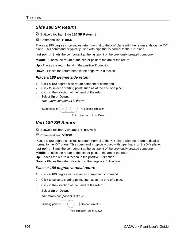
Toolbars Side 180 SR Return
Buttweld toolbar: Side 180 SR Return
Command line: H18SR
Places a 180 degree short radius return normal to the X-Y plane with the return ends on the X-Y plane. This command is typically used with pipe that is normal to the X-Y plane.
last point - Starts the component at the last point of the previously-created component.
Middle - Places the return at the center point of the arc of the return.
Up - Places the return bend in the positive Z direction.
Down - Places the return bend in the negative Z direction.
Place a 180 degree side return 1. Click a 180 degree side return component command. 2. Click to select a starting point, such as at the end of a pipe. 3. Click in the direction of the bend of the return. 4. Select Up or Down.
The return component is drawn.
Vert 180 SR Return Buttweld toolbar: Vert 180 SR Return
Command line: V18SR
Places a 180 degree short radius return normal to the X-Y plane with the return ends also normal to the X-Y plane. This command is typically used with pipe that is on the X-Y plane. last point - Starts the component at the last point of the previously-created component. Middle - Places the return at the center point of the arc of the return. Up - Places the return direction in the positive Z direction. Down - Places the return direction in the negative Z direction.
Place a 180 degree vertical return 1. Click a 180 degree vertical return component command.
2. Click to select a starting point, such as at the end of a pipe.
3. Click in the direction of the bend of the return.
4. Select Up or Down.
The return component is drawn.
396 CADWorx Plant User's Guide

Toolbars Side Cross
Buttweld toolbar: Side Cross
Victaulic toolbar: Side Cross
Command line: HCRSW
Places a four-way straight cross with the branch normal to the X-Y plane.
last point - Starts the component at the last point of the previously-created component.
Middle - Places the cross at the centerline intersection of the cross.
Place a side cross 1. Click a four-way straight side cross command.
2. Click to select a starting point, such as at the end of a pipe.
3. Click in the direction of the cross.
The cross component is drawn.
Side Reducing Cross Buttweld toolbar: Side Reducing Cross
Victaulic toolbar: Side Reducing Cross
Command line: HCRRW
Places a four-way reducing cross with the reducing branch normal to the X-Y plane.
last point - Starts the component at the last point of the previously-created component.
Middle - Places the cross at the centerline intersection of the cross.
Place a side reducing cross 1. Click a four-way side reducing cross command.
2. Click to select a starting point, such as at the end of a pipe.
3. Click in the direction of the cross.
The cross component is drawn.
Vert Reducing Cross Buttweld toolbar: Vert Reducing Cross
Victaulic toolbar: Vert Reducing Cross
Command line: VCRRW
Places a four-way reducing cross with the main normal to the X-Y plane. The center of the cross is placed at the start point by default.
last point - Starts the component at the last point of the previously-created component.
Branch - Places the reducing branch of the cross tee at the start point.
CADWorx Plant User's Guide 397

Toolbars Place a vertical reducing cross 1. Click a four-way vertical reducing cross command.
2. Click to select a starting point, such as at the end of a pipe.
3. Click in the direction of the cross.
The cross component is drawn.
Side Lateral Buttweld toolbar: Side Lateral
Victaulic toolbar: Side Lateral
Command line: HLATW
Places a 45 degree lateral in the X-Y plane with the branch in the X-Z or Y-Z plane.
last point - Starts the component at the last point of the previously-created component.
Middle - Places the lateral at the centerline intersection of the branch and main.
Up - Places the branch of the lateral in the positive Z direction.
Down - Places the branch of the lateral in the negative Z direction.
Place a side lateral 1. Click a side lateral component command. 2. Click to select a starting point, such as at the end of a pipe. 3. Click in the direction of the main of the lateral. 4. Select Up or Down.
The lateral component is drawn.
Vert Lateral Buttweld toolbar: Vert Lateral Victaulic toolbar: Vert Lateral Command line: VLATW
Places a 45 degree lateral with the main normal to the X-Y plane. The center of the lateral is placed at the start point by default. last point - Starts the component at the last point of the previously-created component. Up - Places the branch of the lateral in the positive Z direction. Down - Places the branch of the lateral in the negative Z direction.
Place a vertical lateral 1. Click a vertical lateral component command.
2. Click to select a starting point, such as at the end of a pipe.
3. Click in the direction of the branch of the lateral.
4. Select Up or Down.
The lateral component is drawn.
398 CADWorx Plant User's Guide

Toolbars Side 11.25 Ell
Buttweld toolbar: Side 11.25 Ell
Victaulic toolbar: Side 11.25 Ell
Command line: H11LR
Places an 11.25 degree elbow normal to the X-Y plane. Use this command when the previous or next run is horizontal to the X-Y plane.
last point - Starts the component at the last point of the previously-created component.
Up - Places the elbow bend in the positive Z direction.
Down - Places the elbow bend in the negative Z direction.
Place a side or vertical elbow 1. Click a side or vertical elbow component command. 2. Click to select a starting point, such as at the end of a pipe. 3. Click in the direction of the corner. 4. Select Up or Down.
The elbow component is drawn.
Vert 11.25 Ell Buttweld toolbar: Vert 11.25 Ell
Victaulic toolbar: Vert 11.25 Ell
Command line: V11LR
Places an 11.25 degree elbow normal to the X-Y plane. Use this command when the previous or next run is vertical to the X-Y plane.
last point - Starts the component at the last point of the previously-created component.
Up - Places the elbow bend in the positive Z direction.
Down - Places the elbow bend in the negative Z direction.
Place a side or vertical elbow 1. Click a side or vertical elbow component command. 2. Click to select a starting point, such as at the end of a pipe. 3. Click in the direction of the corner. 4. Select Up or Down.
The elbow component is drawn.
CADWorx Plant User's Guide 399

Toolbars Side 22.5 Ell
Buttweld toolbar: Side 22.5 Ell
Victaulic toolbar: Side 22.5 Ell
Command line: H22LR
Places a 22.5 degree elbow normal to the X-Y plane. Use this command when the previous or next run is horizontal to the X-Y plane.
last point - Starts the component at the last point of the previously-created component.
Up - Places the elbow bend in the positive Z direction.
Down - Places the elbow bend in the negative Z direction.
Place a side or vertical elbow 1. Click a side or vertical elbow component command.
2. Click to select a starting point, such as at the end of a pipe.
3. Click in the direction of the corner.
4. Select Up or Down.
The elbow component is drawn.
Vert 22.5 Ell Buttweld toolbar: Vert 22.5 Ell
Victaulic toolbar: Vert 22.5 Ell
Command line: V22LR
Places a 22.5 degree elbow normal to the X-Y plane. Use this command when the previous or next run is vertical to the X-Y plane. last point - Starts the component at the last point of the previously-created component. Up - Places the elbow bend in the positive Z direction. Down - Places the elbow bend in the negative Z direction.
Place a side or vertical elbow 1. Click a side or vertical elbow component command. 2. Click to select a starting point, such as at the end of a pipe. 3. Click in the direction of the corner. 4. Select Up or Down.
The elbow component is drawn.
400 CADWorx Plant User's Guide
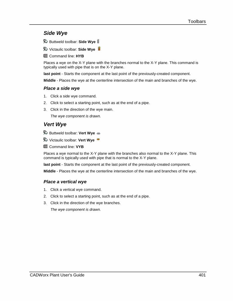
Toolbars Side Wye
Buttweld toolbar: Side Wye
Victaulic toolbar: Side Wye
Command line: HYB
Places a wye on the X-Y plane with the branches normal to the X-Y plane. This command is typically used with pipe that is on the X-Y plane.
last point - Starts the component at the last point of the previously-created component.
Middle - Places the wye at the centerline intersection of the main and branches of the wye.
Place a side wye 1. Click a side wye command.
2. Click to select a starting point, such as at the end of a pipe.
3. Click in the direction of the wye main.
The wye component is drawn.
Vert Wye Buttweld toolbar: Vert Wye
Victaulic toolbar: Vert Wye
Command line: VYB
Places a wye normal to the X-Y plane with the branches also normal to the X-Y plane. This command is typically used with pipe that is normal to the X-Y plane.
last point - Starts the component at the last point of the previously-created component.
Middle - Places the wye at the centerline intersection of the main and branches of the wye.
Place a vertical wye 1. Click a vertical wye command.
2. Click to select a starting point, such as at the end of a pipe.
3. Click in the direction of the wye branches.
The wye component is drawn.
CADWorx Plant User's Guide 401
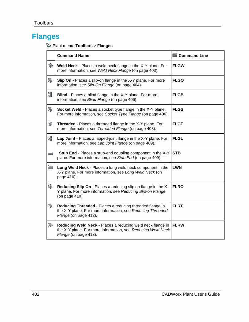
Toolbars
Flanges Plant menu: Toolbars > Flanges
Command Name Command Line
Weld Neck - Places a weld neck flange in the X-Y plane. For more information, see Weld Neck Flange (on page 403).
FLGW
Slip On - Places a slip-on flange in the X-Y plane. For more information, see Slip-On Flange (on page 404).
FLGO
Blind - Places a blind flange in the X-Y plane. For more information, see Blind Flange (on page 406).
FLGB
Socket Weld - Places a socket type flange in the X-Y plane. For more information, see Socket Type Flange (on page 406).
FLGS
Threaded - Places a threaded flange in the X-Y plane. For more information, see Threaded Flange (on page 408).
FLGT
Lap Joint - Places a lapped-joint flange in the X-Y plane. For more information, see Lap Joint Flange (on page 409).
FLGL
Stub End - Places a stub-end coupling component in the X-Y plane. For more information, see Stub End (on page 409).
STB
Long Weld Neck - Places a long weld neck component in the X-Y plane. For more information, see Long Weld Neck (on page 410).
LWN
Reducing Slip On - Places a reducing slip on flange in the X-Y plane. For more information, see Reducing Slip-on Flange (on page 410).
FLRO
Reducing Threaded - Places a reducing threaded flange in the X-Y plane. For more information, see Reducing Threaded Flange (on page 412).
FLRT
Reducing Weld Neck - Places a reducing weld neck flange in the X-Y plane. For more information, see Reducing Weld Neck Flange (on page 413).
FLRW
402 CADWorx Plant User's Guide
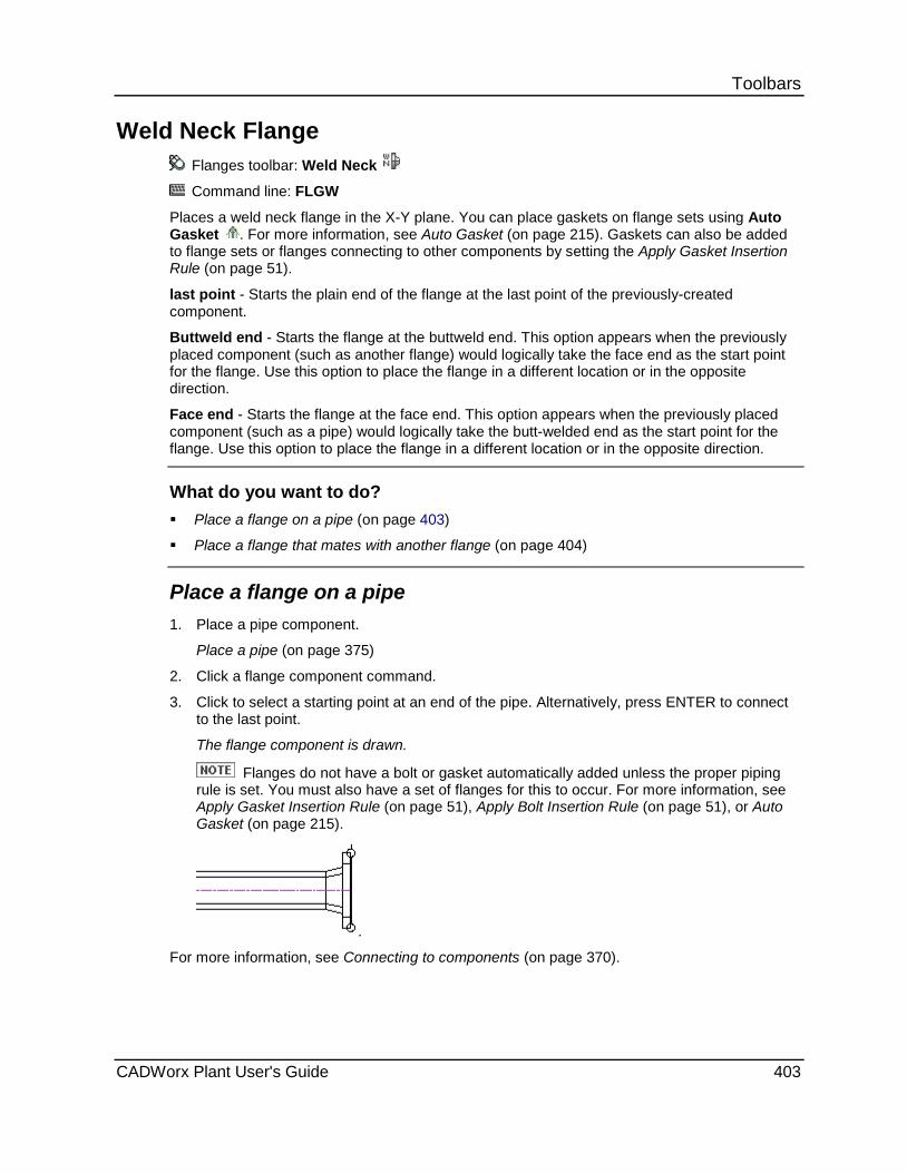
Toolbars
Weld Neck Flange Flanges toolbar: Weld Neck
Command line: FLGW
Places a weld neck flange in the X-Y plane. You can place gaskets on flange sets using Auto Gasket . For more information, see Auto Gasket (on page 215). Gaskets can also be added to flange sets or flanges connecting to other components by setting the Apply Gasket Insertion Rule (on page 51).
last point - Starts the plain end of the flange at the last point of the previously-created component.
Buttweld end - Starts the flange at the buttweld end. This option appears when the previously placed component (such as another flange) would logically take the face end as the start point for the flange. Use this option to place the flange in a different location or in the opposite direction.
Face end - Starts the flange at the face end. This option appears when the previously placed component (such as a pipe) would logically take the butt-welded end as the start point for the flange. Use this option to place the flange in a different location or in the opposite direction.
What do you want to do? Place a flange on a pipe (on page 403)
Place a flange that mates with another flange (on page 404)
Place a flange on a pipe 1. Place a pipe component.
Place a pipe (on page 375)
2. Click a flange component command.
3. Click to select a starting point at an end of the pipe. Alternatively, press ENTER to connect to the last point.
The flange component is drawn.
Flanges do not have a bolt or gasket automatically added unless the proper piping rule is set. You must also have a set of flanges for this to occur. For more information, see Apply Gasket Insertion Rule (on page 51), Apply Bolt Insertion Rule (on page 51), or Auto Gasket (on page 215).
.
For more information, see Connecting to components (on page 370).
CADWorx Plant User's Guide 403
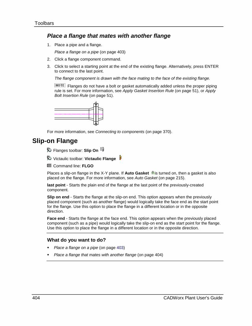
Toolbars Place a flange that mates with another flange 1. Place a pipe and a flange.
Place a flange on a pipe (on page 403)
2. Click a flange component command.
3. Click to select a starting point at the end of the existing flange. Alternatively, press ENTER to connect to the last point.
The flange component is drawn with the face mating to the face of the existing flange.
Flanges do not have a bolt or gasket automatically added unless the proper piping rule is set. For more information, see Apply Gasket Insertion Rule (on page 51), or Apply Bolt Insertion Rule (on page 51).
For more information, see Connecting to components (on page 370).
Slip-on Flange Flanges toolbar: Slip On
Victaulic toolbar: Victaulic Flange
Command line: FLGO
Places a slip-on flange in the X-Y plane. If Auto Gasket is turned on, then a gasket is also placed on the flange. For more information, see Auto Gasket (on page 215).
last point - Starts the plain end of the flange at the last point of the previously-created component.
Slip on end - Starts the flange at the slip-on end. This option appears when the previously placed component (such as another flange) would logically take the face end as the start point for the flange. Use this option to place the flange in a different location or in the opposite direction.
Face end - Starts the flange at the face end. This option appears when the previously placed component (such as a pipe) would logically take the slip-on end as the start point for the flange. Use this option to place the flange in a different location or in the opposite direction.
What do you want to do? Place a flange on a pipe (on page 403)
Place a flange that mates with another flange (on page 404)
404 CADWorx Plant User's Guide

Toolbars Place a flange on a pipe 1. Place a pipe component.
Place a pipe (on page 375)
2. Click a flange component command.
3. Click to select a starting point at an end of the pipe. Alternatively, press ENTER to connect to the last point.
The flange component is drawn.
Flanges do not have a bolt or gasket automatically added unless the proper piping rule is set. You must also have a set of flanges for this to occur. For more information, see Apply Gasket Insertion Rule (on page 51), Apply Bolt Insertion Rule (on page 51), or Auto Gasket (on page 215).
.
For more information, see Connecting to components (on page 370).
Place a flange that mates with another flange 1. Place a pipe and a flange.
Place a flange on a pipe (on page 403)
2. Click a flange component command.
3. Click to select a starting point at the end of the existing flange. Alternatively, press ENTER to connect to the last point.
The flange component is drawn with the face mating to the face of the existing flange.
Flanges do not have a bolt or gasket automatically added unless the proper piping rule is set. For more information, see Apply Gasket Insertion Rule (on page 51), or Apply Bolt Insertion Rule (on page 51).
For more information, see Connecting to components (on page 370).
CADWorx Plant User's Guide 405

Toolbars
Blind Flange Flanges toolbar: Blind
Fiberglass toolbar: FRP Blind Flange
Lined toolbar: Lined Blind Flange
Command line: FLGB
Places a blind flange in the X-Y plane.
last point - Starts the component at the last point of the previously-created component.
Place a flange 1. Click a flange component command.
2. Click to select a starting point. This must be another flange component; otherwise, the system prompts you to add another flange. If prompted, select a flange from the list, and skip step 3.
If you selected a Stub End or a Long Weld Neck the system prompts you to define the length. Type the length as needed, and skip step 3.
3. Click to select the direction of the flange.
The flange component is drawn.
Some of the system prompts you may receive are based on the settings you have defined in the piping rules for Apply Flange Insertion Rule (on page 51) and Default Flange Insertion Type.
Socket Type Flange Flanges toolbar: Socket Weld
Fiberglass toolbar: FRP Flange
Command line: FLGS
Places a socket type flange in the X-Y plane. You can place gaskets on flange sets using Auto Gasket . For more information, see Auto Gasket (on page 215). Gaskets can also be added to flange sets or flanges connecting to other components by setting the Apply Gasket Insertion Rule (on page 51).
last point - Starts the component at the last point of the previously-created component.
Socket end - Starts the flange at the Socket end.
Face end - Starts the flange at the face end.
What do you want to do? Place a flange on a pipe (on page 403)
Place a flange that mates with another flange (on page 404)
406 CADWorx Plant User's Guide

Toolbars Place a flange on a pipe 1. Place a pipe component.
Place a pipe (on page 375)
2. Click a flange component command.
3. Click to select a starting point at an end of the pipe. Alternatively, press ENTER to connect to the last point.
The flange component is drawn.
Flanges do not have a bolt or gasket automatically added unless the proper piping rule is set. You must also have a set of flanges for this to occur. For more information, see Apply Gasket Insertion Rule (on page 51), Apply Bolt Insertion Rule (on page 51), or Auto Gasket (on page 215).
.
For more information, see Connecting to components (on page 370).
Place a flange that mates with another flange 1. Place a pipe and a flange.
Place a flange on a pipe (on page 403)
2. Click a flange component command.
3. Click to select a starting point at the end of the existing flange. Alternatively, press ENTER to connect to the last point.
The flange component is drawn with the face mating to the face of the existing flange.
Flanges do not have a bolt or gasket automatically added unless the proper piping rule is set. For more information, see Apply Gasket Insertion Rule (on page 51), or Apply Bolt Insertion Rule (on page 51).
For more information, see Connecting to components (on page 370).
CADWorx Plant User's Guide 407

Toolbars
Threaded Flange Flanges toolbar: Threaded
Command line: FLGT
Places a threaded flange in the X-Y plane. You can place gaskets on flange sets using Auto Gasket . For more information, see Auto Gasket (on page 215). Gaskets can also be added to flange sets or flanges connecting to other components by setting the Apply Gasket Insertion Rule (on page 51).
last point - Starts the component at the last point of the previously-created component.
Thread end - Starts the flange at the threaded end.
Face end - Starts the flange at the face end.
What do you want to do? Place a flange on a pipe (on page 403)
Place a flange that mates with another flange (on page 404)
Place a flange on a pipe 1. Place a pipe component.
Place a pipe (on page 375)
2. Click a flange component command.
3. Click to select a starting point at an end of the pipe. Alternatively, press ENTER to connect to the last point.
The flange component is drawn.
Flanges do not have a bolt or gasket automatically added unless the proper piping rule is set. You must also have a set of flanges for this to occur. For more information, see Apply Gasket Insertion Rule (on page 51), Apply Bolt Insertion Rule (on page 51), or Auto Gasket (on page 215).
.
For more information, see Connecting to components (on page 370).
Place a flange that mates with another flange 1. Place a pipe and a flange.
Place a flange on a pipe (on page 403)
2. Click a flange component command.
408 CADWorx Plant User's Guide

Toolbars 3. Click to select a starting point at the end of the existing flange. Alternatively, press ENTER
to connect to the last point.
The flange component is drawn with the face mating to the face of the existing flange.
Flanges do not have a bolt or gasket automatically added unless the proper piping rule is set. For more information, see Apply Gasket Insertion Rule (on page 51), or Apply Bolt Insertion Rule (on page 51).
For more information, see Connecting to components (on page 370).
Lap Joint Flange Flanges toolbar: Lap Joint Command line: FLGL
Places a lapped-joint flange in the X-Y plane. last point - Starts the component at the last point of the previously-created component.
Place a flange 1. Click a flange component command.
2. Click to select a starting point. This must be another flange component; otherwise, the system prompts you to add another flange. If prompted, select a flange from the list, and skip step 3.
If you selected a Stub End or a Long Weld Neck the system prompts you to define the length. Type the length as needed, and skip step 3.
3. Click to select the direction of the flange.
The flange component is drawn.
Some of the system prompts you may receive are based on the settings you have defined in the piping rules for Apply Flange Insertion Rule (on page 51) and Default Flange Insertion Type.
Stub End Flanges toolbar: Stub End
Command line: STB
Places a stub-end coupling component in the X-Y plane. You can place gaskets on flange sets using Auto Gasket . For more information, see Auto Gasket (on page 215). Gaskets can also be added to flange sets or flanges connecting to other components by setting the Apply Gasket Insertion Rule (on page 51).
Length - Defines the length of the stub-end. If no length is defined, the default value from the current specification is used.
Plan end - Starts the stub at the plain end.
Face end - Starts the stub at the face end.
CADWorx Plant User's Guide 409

Toolbars Place a stub or weld neck 1. Click a stub or weld neck component command. 2. If needed, select Length and type a length for the component. 3. Pick a starting point, such as at the end of a pipe. Alternatively, press ENTER to connect to
the last point. The component is drawn.
Long Weld Neck Flanges toolbar: Long Weld Neck
Command line: LWN
Places a long weld neck component in the X-Y plane. Length - Defines the length of the stub-end. If no length is defined, the default value from the current specification is used. Plan end - Starts the stub at the plain end. Face end - Starts the stub at the face end.
Place a stub or weld neck 1. Click a stub or weld neck component command. 2. If needed, select Length and type a length for the component. 3. Pick a starting point, such as at the end of a pipe. Alternatively, press ENTER to connect to
the last point. The component is drawn.
Reducing Slip-on Flange Flanges toolbar: Reducing Slip On Lined toolbar: Lined Reducing Flange Command line: FLRO
Places a reducing slip-on flange in the X-Y plane. You can place gaskets on flange sets using Auto Gasket . For more information, see Auto Gasket (on page 215). Gaskets can also be added to flange sets or flanges connecting to other components by setting the Apply Gasket Insertion Rule (on page 51). last point - Starts the plain end of the flange at the last point of the previously-created component. Reducing end - Starts the flange at the reducing end. This option appears when the previously placed component (such as another flange) would logically take the face end as the start point for the flange. Use this option to place the flange in a different location or in the opposite direction. Face end - Starts the flange at the face end. This option appears when the previously placed component (such as a pipe) would logically take the reducing end as the start point for the flange. Use this option to place the flange in a different location or in the opposite direction.
What do you want to do? Place a flange on a pipe (on page 403) Place a flange that mates with another flange (on page 404)
410 CADWorx Plant User's Guide
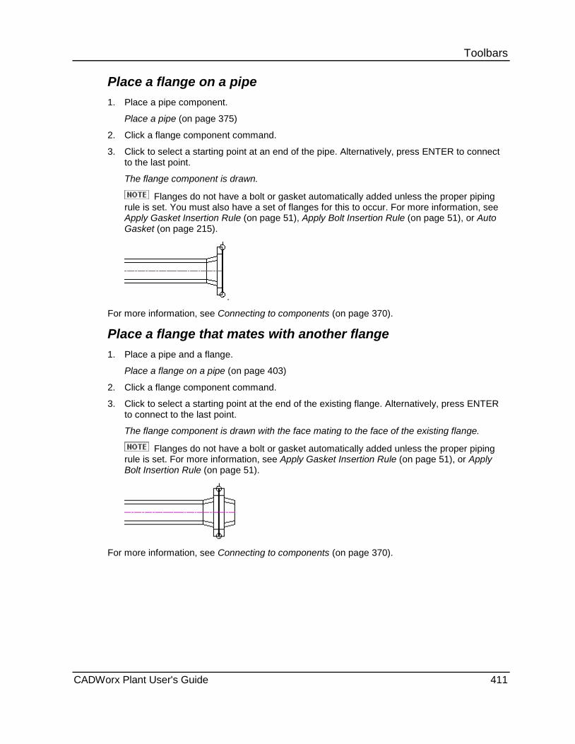
Toolbars Place a flange on a pipe 1. Place a pipe component.
Place a pipe (on page 375)
2. Click a flange component command.
3. Click to select a starting point at an end of the pipe. Alternatively, press ENTER to connect to the last point.
The flange component is drawn.
Flanges do not have a bolt or gasket automatically added unless the proper piping rule is set. You must also have a set of flanges for this to occur. For more information, see Apply Gasket Insertion Rule (on page 51), Apply Bolt Insertion Rule (on page 51), or Auto Gasket (on page 215).
.
For more information, see Connecting to components (on page 370).
Place a flange that mates with another flange 1. Place a pipe and a flange.
Place a flange on a pipe (on page 403)
2. Click a flange component command.
3. Click to select a starting point at the end of the existing flange. Alternatively, press ENTER to connect to the last point.
The flange component is drawn with the face mating to the face of the existing flange.
Flanges do not have a bolt or gasket automatically added unless the proper piping rule is set. For more information, see Apply Gasket Insertion Rule (on page 51), or Apply Bolt Insertion Rule (on page 51).
For more information, see Connecting to components (on page 370).
CADWorx Plant User's Guide 411

Toolbars
Reducing Threaded Flange Flanges toolbar: Reducing Threaded
Command line: FLRT
Places a reducing threaded flange in the X-Y plane. You can place gaskets on flange sets using Auto Gasket . For more information, see Auto Gasket (on page 215). Gaskets can also be added to flange sets or flanges connecting to other components by setting the Apply Gasket Insertion Rule (on page 51).
last point - Starts the plain end of the flange at the last point of the previously-created component.
Reducing end - Starts the flange at the reducing end. This option appears when the previously placed component (such as another flange) would logically take the face end as the start point for the flange. Use this option to place the flange in a different location or in the opposite direction.
Face end - Starts the flange at the face end. This option appears when the previously placed component (such as a pipe) would logically take the reducing end as the start point for the flange. Use this option to place the flange in a different location or in the opposite direction.
What do you want to do? Place a flange on a pipe (on page 403)
Place a flange that mates with another flange (on page 404)
Place a flange on a pipe 1. Place a pipe component.
Place a pipe (on page 375)
2. Click a flange component command.
3. Click to select a starting point at an end of the pipe. Alternatively, press ENTER to connect to the last point.
The flange component is drawn.
Flanges do not have a bolt or gasket automatically added unless the proper piping rule is set. You must also have a set of flanges for this to occur. For more information, see Apply Gasket Insertion Rule (on page 51), Apply Bolt Insertion Rule (on page 51), or Auto Gasket (on page 215).
.
For more information, see Connecting to components (on page 370).
412 CADWorx Plant User's Guide

Toolbars Place a flange that mates with another flange 1. Place a pipe and a flange.
Place a flange on a pipe (on page 403)
2. Click a flange component command.
3. Click to select a starting point at the end of the existing flange. Alternatively, press ENTER to connect to the last point.
The flange component is drawn with the face mating to the face of the existing flange.
Flanges do not have a bolt or gasket automatically added unless the proper piping rule is set. For more information, see Apply Gasket Insertion Rule (on page 51), or Apply Bolt Insertion Rule (on page 51).
For more information, see Connecting to components (on page 370).
Reducing Weld Neck Flange Flanges toolbar: Reducing Weld Neck
Command line: FLRW
Places a reducing weld neck flange in the X-Y plane. You can place gaskets on flange sets using Auto Gasket . For more information, see Auto Gasket (on page 215). Gaskets can also be added to flange sets or flanges connecting to other components by setting the Apply Gasket Insertion Rule (on page 51).
last point - Starts the plain end of the flange at the last point of the previously-created component.
Reducing end - Starts the flange at the reducing end. This option appears when the previously placed component (such as another flange) would logically take the face end as the start point for the flange. Use this option to place the flange in a different location or in the opposite direction.
Face end - Starts the flange at the face end. This option appears when the previously placed component (such as a pipe) would logically take the reducing end as the start point for the flange. Use this option to place the flange in a different location or in the opposite direction.
What do you want to do? Place a flange on a pipe (on page 403)
Place a flange that mates with another flange (on page 404)
CADWorx Plant User's Guide 413
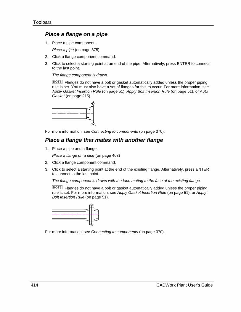
Toolbars Place a flange on a pipe 1. Place a pipe component.
Place a pipe (on page 375)
2. Click a flange component command.
3. Click to select a starting point at an end of the pipe. Alternatively, press ENTER to connect to the last point.
The flange component is drawn.
Flanges do not have a bolt or gasket automatically added unless the proper piping rule is set. You must also have a set of flanges for this to occur. For more information, see Apply Gasket Insertion Rule (on page 51), Apply Bolt Insertion Rule (on page 51), or Auto Gasket (on page 215).
.
For more information, see Connecting to components (on page 370).
Place a flange that mates with another flange 1. Place a pipe and a flange.
Place a flange on a pipe (on page 403)
2. Click a flange component command.
3. Click to select a starting point at the end of the existing flange. Alternatively, press ENTER to connect to the last point.
The flange component is drawn with the face mating to the face of the existing flange.
Flanges do not have a bolt or gasket automatically added unless the proper piping rule is set. For more information, see Apply Gasket Insertion Rule (on page 51), or Apply Bolt Insertion Rule (on page 51).
For more information, see Connecting to components (on page 370).
414 CADWorx Plant User's Guide
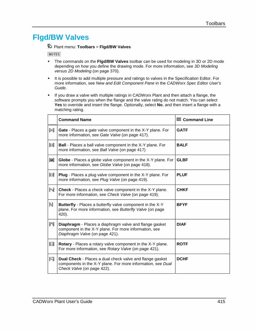
Toolbars
Flgd/BW Valves Plant menu: Toolbars > Flgd/BW Valves
The commands on the Flgd/BW Valves toolbar can be used for modeling in 3D or 2D mode
depending on how you define the drawing mode. For more information, see 3D Modeling versus 2D Modeling (on page 370).
It is possible to add multiple pressure and ratings to valves in the Specification Editor. For more information, see New and Edit Component Pane in the CADWorx Spec Editor User's Guide.
If you draw a valve with multiple ratings in CADWorx Plant and then attach a flange, the software prompts you when the flange and the valve rating do not match. You can select Yes to override and insert the flange. Optionally, select No, and then insert a flange with a matching rating.
Command Name Command Line
Gate - Places a gate valve component in the X-Y plane. For more information, see Gate Valve (on page 417).
GATF
Ball - Places a ball valve component in the X-Y plane. For more information, see Ball Valve (on page 417)
BALF
Globe - Places a globe valve component in the X-Y plane. For more information, see Globe Valve (on page 418).
GLBF
Plug - Places a plug valve component in the X-Y plane. For more information, see Plug Valve (on page 419).
PLUF
Check - Places a check valve component in the X-Y plane. For more information, see Check Valve (on page 419).
CHKF
Butterfly - Places a butterfly valve component in the X-Y plane. For more information, see Butterfly Valve (on page 420).
BFYF
Diaphragm - Places a diaphragm valve and flange gasket component in the X-Y plane. For more information, see Diaphragm Valve (on page 421).
DIAF
Rotary - Places a rotary valve component in the X-Y plane. For more information, see Rotary Valve (on page 421).
ROTF
Dual Check - Places a dual check valve and flange gasket components in the X-Y plane. For more information, see Dual Check Valve (on page 422).
DCHF
CADWorx Plant User's Guide 415
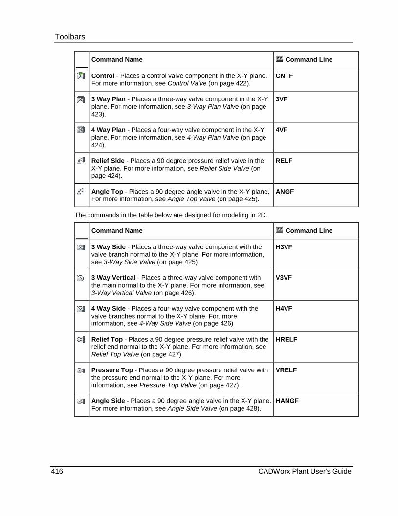
Toolbars
Command Name Command Line
Control - Places a control valve component in the X-Y plane. For more information, see Control Valve (on page 422).
CNTF
3 Way Plan - Places a three-way valve component in the X-Y plane. For more information, see 3-Way Plan Valve (on page 423).
3VF
4 Way Plan - Places a four-way valve component in the X-Y plane. For more information, see 4-Way Plan Valve (on page 424).
4VF
Relief Side - Places a 90 degree pressure relief valve in the X-Y plane. For more information, see Relief Side Valve (on page 424).
RELF
Angle Top - Places a 90 degree angle valve in the X-Y plane. For more information, see Angle Top Valve (on page 425).
ANGF
The commands in the table below are designed for modeling in 2D.
Command Name Command Line
3 Way Side - Places a three-way valve component with the valve branch normal to the X-Y plane. For more information, see 3-Way Side Valve (on page 425)
H3VF
3 Way Vertical - Places a three-way valve component with the main normal to the X-Y plane. For more information, see 3-Way Vertical Valve (on page 426).
V3VF
4 Way Side - Places a four-way valve component with the valve branches normal to the X-Y plane. For. more information, see 4-Way Side Valve (on page 426)
H4VF
Relief Top - Places a 90 degree pressure relief valve with the relief end normal to the X-Y plane. For more information, see Relief Top Valve (on page 427)
HRELF
Pressure Top - Places a 90 degree pressure relief valve with the pressure end normal to the X-Y plane. For more information, see Pressure Top Valve (on page 427).
VRELF
Angle Side - Places a 90 degree angle valve in the X-Y plane. For more information, see Angle Side Valve (on page 428).
HANGF
416 CADWorx Plant User's Guide

Toolbars
Modeling in 3D These commands are useful for 3D modeling. All of the following commands are available in 3D and 2D modeling.
Gate Valve Flanged Valves toolbar: Gate
Command line: GATF
Places a gate valve component in the X-Y plane. You can place gaskets on flange sets using Auto Gasket . For more information, see Auto Gasket (on page 215). Gaskets can also be added to flange sets or flanges connecting to other components by setting the Apply Gasket Insertion Rule (on page 51).
last point - Starts the plain end of the valve at the last point of the previously-created component.
Middle - Places the valve at its center.
Place a valve 1. Click a valve component command.
2. Click to select a starting point, such as at the end of a pipe or a flange.
Alternatively, press ENTER to connect to the last point. This works only when connecting to a flange, otherwise follow the prompts provided by the software.
The valve component is drawn.
For more information, see Connecting to components (on page 370).
Ball Valve Flanged Valves toolbar: Ball
Victaulic toolbar: Victaulic Ball Valve
Command line: BALF
Places a ball valve component in the X-Y plane. You can place gaskets on flange sets using Auto Gasket . For more information, see Auto Gasket (on page 215). Gaskets can also be added to flange sets or flanges connecting to other components by setting the Apply Gasket Insertion Rule (on page 51).
last point - Starts the plain end of the valve at the last point of the previously-created component.
Middle - Places the valve at its center.
CADWorx Plant User's Guide 417
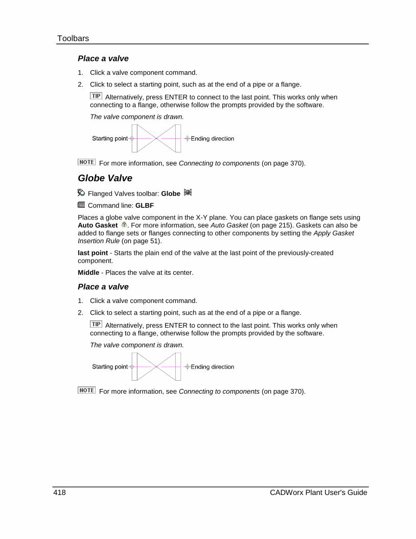
Toolbars Place a valve 1. Click a valve component command.
2. Click to select a starting point, such as at the end of a pipe or a flange.
Alternatively, press ENTER to connect to the last point. This works only when connecting to a flange, otherwise follow the prompts provided by the software.
The valve component is drawn.
For more information, see Connecting to components (on page 370).
Globe Valve Flanged Valves toolbar: Globe
Command line: GLBF
Places a globe valve component in the X-Y plane. You can place gaskets on flange sets using Auto Gasket . For more information, see Auto Gasket (on page 215). Gaskets can also be added to flange sets or flanges connecting to other components by setting the Apply Gasket Insertion Rule (on page 51).
last point - Starts the plain end of the valve at the last point of the previously-created component.
Middle - Places the valve at its center.
Place a valve 1. Click a valve component command.
2. Click to select a starting point, such as at the end of a pipe or a flange.
Alternatively, press ENTER to connect to the last point. This works only when connecting to a flange, otherwise follow the prompts provided by the software.
The valve component is drawn.
For more information, see Connecting to components (on page 370).
418 CADWorx Plant User's Guide
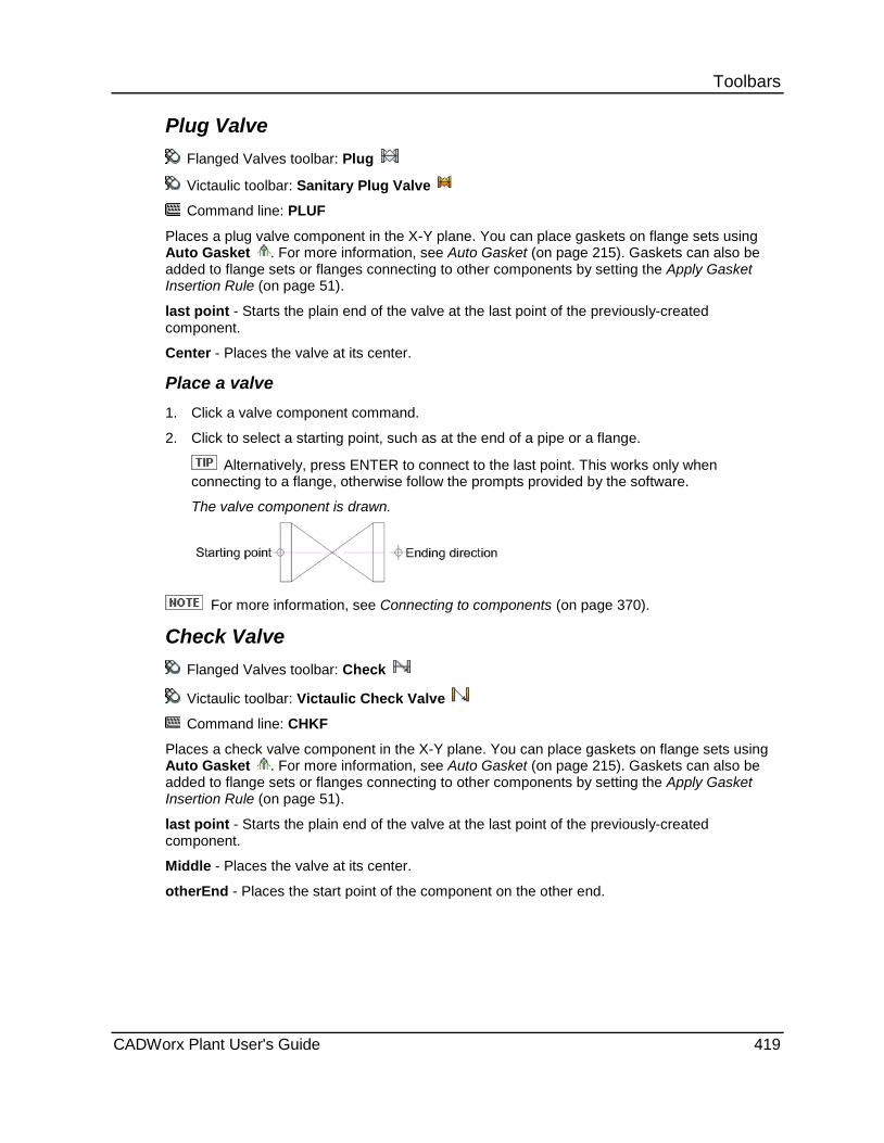
Toolbars Plug Valve
Flanged Valves toolbar: Plug
Victaulic toolbar: Sanitary Plug Valve
Command line: PLUF
Places a plug valve component in the X-Y plane. You can place gaskets on flange sets using Auto Gasket . For more information, see Auto Gasket (on page 215). Gaskets can also be added to flange sets or flanges connecting to other components by setting the Apply Gasket Insertion Rule (on page 51).
last point - Starts the plain end of the valve at the last point of the previously-created component.
Center - Places the valve at its center.
Place a valve 1. Click a valve component command.
2. Click to select a starting point, such as at the end of a pipe or a flange.
Alternatively, press ENTER to connect to the last point. This works only when connecting to a flange, otherwise follow the prompts provided by the software.
The valve component is drawn.
For more information, see Connecting to components (on page 370).
Check Valve Flanged Valves toolbar: Check
Victaulic toolbar: Victaulic Check Valve
Command line: CHKF
Places a check valve component in the X-Y plane. You can place gaskets on flange sets using Auto Gasket . For more information, see Auto Gasket (on page 215). Gaskets can also be added to flange sets or flanges connecting to other components by setting the Apply Gasket Insertion Rule (on page 51).
last point - Starts the plain end of the valve at the last point of the previously-created component.
Middle - Places the valve at its center.
otherEnd - Places the start point of the component on the other end.
CADWorx Plant User's Guide 419
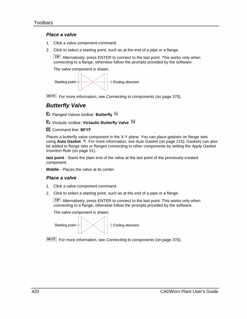
Toolbars Place a valve 1. Click a valve component command.
2. Click to select a starting point, such as at the end of a pipe or a flange.
Alternatively, press ENTER to connect to the last point. This works only when connecting to a flange, otherwise follow the prompts provided by the software.
The valve component is drawn.
For more information, see Connecting to components (on page 370).
Butterfly Valve Flanged Valves toolbar: Butterfly
Victaulic toolbar: Victaulic Butterfly Valve
Command line: BFYF
Places a butterfly valve component in the X-Y plane. You can place gaskets on flange sets using Auto Gasket . For more information, see Auto Gasket (on page 215). Gaskets can also be added to flange sets or flanges connecting to other components by setting the Apply Gasket Insertion Rule (on page 51).
last point - Starts the plain end of the valve at the last point of the previously-created component.
Middle - Places the valve at its center.
Place a valve 1. Click a valve component command.
2. Click to select a starting point, such as at the end of a pipe or a flange.
Alternatively, press ENTER to connect to the last point. This works only when connecting to a flange, otherwise follow the prompts provided by the software.
The valve component is drawn.
For more information, see Connecting to components (on page 370).
420 CADWorx Plant User's Guide
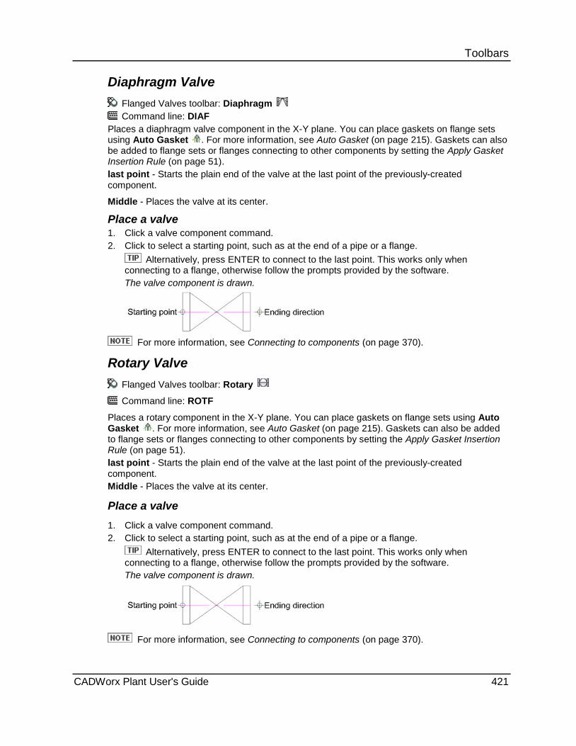
Toolbars Diaphragm Valve
Flanged Valves toolbar: Diaphragm Command line: DIAF
Places a diaphragm valve component in the X-Y plane. You can place gaskets on flange sets using Auto Gasket . For more information, see Auto Gasket (on page 215). Gaskets can also be added to flange sets or flanges connecting to other components by setting the Apply Gasket Insertion Rule (on page 51). last point - Starts the plain end of the valve at the last point of the previously-created component.
Middle - Places the valve at its center.
Place a valve 1. Click a valve component command. 2. Click to select a starting point, such as at the end of a pipe or a flange.
Alternatively, press ENTER to connect to the last point. This works only when connecting to a flange, otherwise follow the prompts provided by the software. The valve component is drawn.
For more information, see Connecting to components (on page 370).
Rotary Valve Flanged Valves toolbar: Rotary
Command line: ROTF
Places a rotary component in the X-Y plane. You can place gaskets on flange sets using Auto Gasket . For more information, see Auto Gasket (on page 215). Gaskets can also be added to flange sets or flanges connecting to other components by setting the Apply Gasket Insertion Rule (on page 51). last point - Starts the plain end of the valve at the last point of the previously-created component. Middle - Places the valve at its center.
Place a valve 1. Click a valve component command. 2. Click to select a starting point, such as at the end of a pipe or a flange.
Alternatively, press ENTER to connect to the last point. This works only when connecting to a flange, otherwise follow the prompts provided by the software. The valve component is drawn.
For more information, see Connecting to components (on page 370).
CADWorx Plant User's Guide 421

Toolbars Dual Check Valve
Flanged Valves toolbar: Dual Check
Command line: DCHF
Places a dual check valve component in the X-Y plane. You can place gaskets on flange sets using Auto Gasket . For more information, see Auto Gasket (on page 215). Gaskets can also be added to flange sets or flanges connecting to other components by setting the Apply Gasket Insertion Rule (on page 51).
last point - Starts the plain end of the valve at the last point of the previously-created component.
Middle - Places the valve at its center.
otherEnd - Places the start point of the component on the other end.
Place a valve 1. Click a valve component command.
2. Click to select a starting point, such as at the end of a pipe or a flange.
Alternatively, press ENTER to connect to the last point. This works only when connecting to a flange, otherwise follow the prompts provided by the software.
The valve component is drawn.
For more information, see Connecting to components (on page 370).
Control Valve Flanged Valves toolbar: Control
Command line: CNTF
Places a control valve component in the X-Y plane. You can place gaskets on flange sets using Auto Gasket . For more information, see Auto Gasket (on page 215). Gaskets can also be added to flange sets or flanges connecting to other components by setting the Apply Gasket Insertion Rule (on page 51).
last point - Starts the plain end of the valve at the last point of the previously-created component.
Length - Specifies the length of the valve.
Center - Places the valve at its center.
422 CADWorx Plant User's Guide
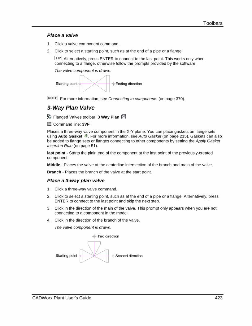
Toolbars Place a valve 1. Click a valve component command.
2. Click to select a starting point, such as at the end of a pipe or a flange.
Alternatively, press ENTER to connect to the last point. This works only when connecting to a flange, otherwise follow the prompts provided by the software.
The valve component is drawn.
For more information, see Connecting to components (on page 370).
3-Way Plan Valve Flanged Valves toolbar: 3 Way Plan
Command line: 3VF
Places a three-way valve component in the X-Y plane. You can place gaskets on flange sets using Auto Gasket . For more information, see Auto Gasket (on page 215). Gaskets can also be added to flange sets or flanges connecting to other components by setting the Apply Gasket Insertion Rule (on page 51).
last point - Starts the plain end of the component at the last point of the previously-created component.
Middle - Places the valve at the centerline intersection of the branch and main of the valve.
Branch - Places the branch of the valve at the start point.
Place a 3-way plan valve 1. Click a three-way valve command.
2. Click to select a starting point, such as at the end of a pipe or a flange. Alternatively, press ENTER to connect to the last point and skip the next step.
3. Click in the direction of the main of the valve. This prompt only appears when you are not connecting to a component in the model.
4. Click in the direction of the branch of the valve.
The valve component is drawn.
CADWorx Plant User's Guide 423
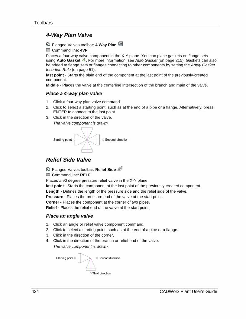
Toolbars 4-Way Plan Valve
Flanged Valves toolbar: 4 Way Plan Command line: 4VF
Places a four-way valve component in the X-Y plane. You can place gaskets on flange sets using Auto Gasket . For more information, see Auto Gasket (on page 215). Gaskets can also be added to flange sets or flanges connecting to other components by setting the Apply Gasket Insertion Rule (on page 51). last point - Starts the plain end of the component at the last point of the previously-created component. Middle - Places the valve at the centerline intersection of the branch and main of the valve.
Place a 4-way plan valve 1. Click a four-way plan valve command. 2. Click to select a starting point, such as at the end of a pipe or a flange. Alternatively, press
ENTER to connect to the last point. 3. Click in the direction of the valve.
The valve component is drawn.
Relief Side Valve Flanged Valves toolbar: Relief Side Command line: RELF
Places a 90 degree pressure relief valve in the X-Y plane. last point - Starts the component at the last point of the previously-created component. Length - Defines the length of the pressure side and the relief side of the valve. Pressure - Places the pressure end of the valve at the start point. Corner - Places the component at the corner of two pipes. Relief - Places the relief end of the valve at the start point.
Place an angle valve 1. Click an angle or relief valve component command. 2. Click to select a starting point, such as at the end of a pipe or a flange. 3. Click in the direction of the corner. 4. Click in the direction of the branch or relief end of the valve.
The valve component is drawn.
424 CADWorx Plant User's Guide
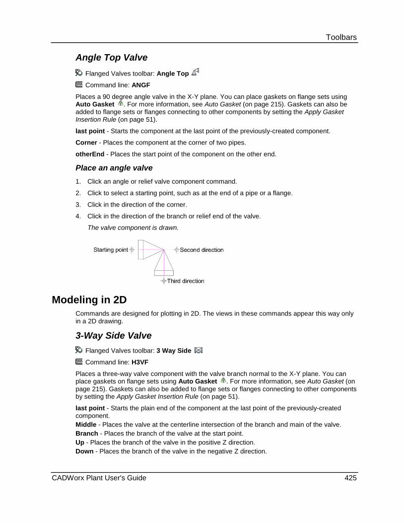
Toolbars Angle Top Valve
Flanged Valves toolbar: Angle Top
Command line: ANGF
Places a 90 degree angle valve in the X-Y plane. You can place gaskets on flange sets using Auto Gasket . For more information, see Auto Gasket (on page 215). Gaskets can also be added to flange sets or flanges connecting to other components by setting the Apply Gasket Insertion Rule (on page 51).
last point - Starts the component at the last point of the previously-created component.
Corner - Places the component at the corner of two pipes.
otherEnd - Places the start point of the component on the other end.
Place an angle valve 1. Click an angle or relief valve component command.
2. Click to select a starting point, such as at the end of a pipe or a flange.
3. Click in the direction of the corner.
4. Click in the direction of the branch or relief end of the valve.
The valve component is drawn.
Modeling in 2D Commands are designed for plotting in 2D. The views in these commands appear this way only in a 2D drawing.
3-Way Side Valve Flanged Valves toolbar: 3 Way Side
Command line: H3VF
Places a three-way valve component with the valve branch normal to the X-Y plane. You can place gaskets on flange sets using Auto Gasket . For more information, see Auto Gasket (on page 215). Gaskets can also be added to flange sets or flanges connecting to other components by setting the Apply Gasket Insertion Rule (on page 51).
last point - Starts the plain end of the component at the last point of the previously-created component. Middle - Places the valve at the centerline intersection of the branch and main of the valve. Branch - Places the branch of the valve at the start point. Up - Places the branch of the valve in the positive Z direction. Down - Places the branch of the valve in the negative Z direction.
CADWorx Plant User's Guide 425
Toolbars Place a 3-way side valve 1. Click a three-way side valve component command.
2. Click to select a starting point, such as at the end of a pipe or a flange.
3. Click in the direction of the main of the valve.
4. Select Up or Down.
The valve component is drawn.
3-Way Vertical Valve Flanged Valves toolbar: 3 Way Vertical
Command line: V3VF
Places a three-way valve component with the main normal to the X-Y plane. You can place gaskets on flange sets using Auto Gasket . For more information, see Auto Gasket (on page 215). Gaskets can also be added to flange sets or flanges connecting to other components by setting the Apply Gasket Insertion Rule (on page 51).
last point - Starts the plain end of the component at the last point of the previously-created component.
Middle - Places the valve at the centerline intersection of the branch and main of the valve.
Place a 3-way vertical valve 1. Click a three-way vertical valve component command.
2. Click to select a starting point, such as at the end of a pipe or a flange.
3. Click in the direction of the branch of the valve.
The valve component is drawn.
4-Way Side Valve Flanged Valves toolbar: 4 Way Side
Command line: H4VF
Places a four-way valve component with the valve branches normal to the X-Y plane. You can place gaskets on flange sets using Auto Gasket . For more information, see Auto Gasket (on page 215). Gaskets can also be added to flange sets or flanges connecting to other components by setting the Apply Gasket Insertion Rule (on page 51).
last point - Starts the plain end of the component at the last point of the previously-created component.
Middle - Places the valve at the centerline intersection of the branch and main of the valve.
Place a 4-way side valve 1. Click a four-way side valve command.
2. Click to select a starting point, such as at the end of a pipe or a flange.
3. Click in the direction of the valve.
The valve component is drawn.
426 CADWorx Plant User's Guide
Toolbars Relief Top Valve
Flanged Valves toolbar: Relief Top
Command line: HRELF
Places a 90 degree pressure relief valve with the relief end normal to the X-Y plane.
last point - Starts the component at the last point of the previously-created component.
Length - Defines the length of the pressure side and the relief side of the valve.
Relief - Places the relief end at the start point.
Corner - Places the component at the corner of two pipes.
Up - Places the branch of the valve in the positive Z direction.
Down - Places the branch of the valve in the negative Z direction.
Place an angle side valve 1. Click an angle or relief side valve component command.
2. Click to select a starting point, such as at the end of a pipe.
3. Click in the direction of the main of the valve.
4. Select Up or Down.
The valve component is drawn.
Pressure Top Valve Flanged Valves toolbar: Pressure Top
Command line: VRELF
Places a 90 degree pressure relief valve with the pressure end normal to the X-Y plane.
last point - Starts the component at the last point of the previously-created component.
Length - Defines the length of the pressure side and the relief side of the valve.
Pressure - Places the pressure end of the valve at the start point.
Corner - Places the component at the corner of two pipes.
Up - Places the branch of the valve in the positive Z direction.
Down - Places the branch of the valve in the negative Z direction.
Place an angle side valve 1. Click an angle or relief side valve component command.
2. Click to select a starting point, such as at the end of a pipe.
3. Click in the direction of the main of the valve.
4. Select Up or Down.
The valve component is drawn.
CADWorx Plant User's Guide 427

Toolbars Angle Side Valve
Flanged Valves toolbar: Angle Side
Command line: HANGF
Places a 90 degree angle valve in the X-Y plane. You can place gaskets on flange sets using Auto Gasket . For more information, see Auto Gasket (on page 215). Gaskets can also be added to flange sets or flanges connecting to other components by setting the Apply Gasket Insertion Rule (on page 51).
last point - Starts the component at the last point of the previously-created component.
Corner - Places the component at the corner of two pipes.
Up - Places the branch of the valve in the positive Z direction.
Down - Places the branch of the valve in the negative Z direction.
Place an angle side valve 1. Click an angle or relief side valve component command.
2. Click to select a starting point, such as at the end of a pipe.
3. Click in the direction of the main of the valve.
4. Select Up or Down.
The valve component is drawn.
Lined Plant menu: Toolbars > Lined
The commands on the Lined toolbar can be used for modeling in 3D or 2D mode depending on how you define the drawing mode. For more information, see 3D Modeling versus 2D Modeling (on page 370).
Command Name Command Line
Lined Pipe - Places a flanged and lined pipe component in the X-Y plane. For more information, see Lined Pipe (on page 431).
PIPFL
Lined 90 Ell Plan - Places a 90 degree flanged and lined elbow in the X-Y plane. For more information, see Flanged 90 Degree Elbow Plan (on page 442).
90FL
Lined 45 Ell Plan - Places a 45 degree flanged and lined elbow in the X-Y plane. For more information, see Flanged 45 Degree Elbow Plan (on page 443).
45FL
Lined Tee Plan - Places a flanged and lined tee in the X-Y plane. For more information, see Flanged Tee Plan (on page 444).
TEFL
Lined Reducing Tee Plan - Places a flanged and lined reducing tee in the X-Y plane. For more information, see Reducing Tee Plan (on page 461).
TERE
428 CADWorx Plant User's Guide

Toolbars Command Name Command Line
Lined Concentric - Places a flanged and lined concentric reducer component in the X-Y plane. For more information, see Flanged Concentric Reducer (on page 444).
CNFL
Lined Eccentric - Places a flanged and lined eccentric reducer component in the X-Y plane. For more information, see Lined Eccentric Reducer (on page 431).
ECFL
Lined Wye Plan - Places a flanged and lined wye in the X-Y plane. For more information, see Lined Wye Plan (on page 432).
YFL
Lined Cross Plan - Places a four-way flanged and lined cross in the X-Y plane. For more information, see Cross Plan (on page 462).
CRSE
Lined Reducing Cross Plan - Places a four-way flanged and lined reducing cross in the X-Y plane. For more information, see Cross Reducing Plan (on page 462).
CRRE
Lined Lateral Plan - Places a 45 degree flanged and lined lateral in the X-Y plane. For more information, see Lateral Plan (on page 463).
LATE
Lined Spacer - Places a lined spacer in the X-Y plane. For more information, see Bleed Ring or Spacer (on page 544).
BLD
Lined Reducing Flange - Places a lined reducing flange in the X-Y plane. For more information, see Reducing Slip-on Flange (on page 410).
FLRO
Lined Blind Flange - Places a lined blind flange in the X-Y plane. For more information, see Blind Flange (on page 406).
FLGB
The commands in the table below are designed for modeling in 2D.
Command Name Command Line
Lined 90 Ell Side - Places a 90 degree flanged and lined elbow normal to the X-Y plane. For more information, see Flanged 90 Degree Elbow Side (on page 449).
H90FL
Lined 45 Ell Side - Places a 45 degree flanged and lined elbow normal to the X-Y plane. For more information, see Flanged 45 Degree Elbow Side (on page 450).
H45FL
Lined 45 Ell Vert - Places a 45 degree flanged and lined elbow normal to the X-Y plane. For more information, see Flanged 45 Degree Elbow Vert (on page 450).
V45FL
Lined Tee Side - Places a flanged and lined tee with the branch normal to the X-Y plane. For more information, see Flanged Tee Side (on page 451).
HTEFL
CADWorx Plant User's Guide 429
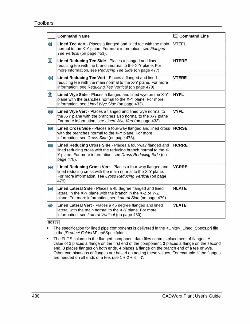
Toolbars Command Name Command Line
Lined Tee Vert - Places a flanged and lined tee with the main normal to the X-Y plane. For more information, see Flanged Tee Vertical (on page 451).
VTEFL
Lined Reducing Tee Side - Places a flanged and lined reducing tee with the branch normal to the X-Y plane. For more information, see Reducing Tee Side (on page 477)
HTERE
Lined Reducing Tee Vert - Places a flanged and lined reducing tee with the main normal to the X-Y plane. For more information, see Reducing Tee Vertical (on page 478).
VTERE
Lined Wye Side - Places a flanged and lined wye on the X-Y plane with the branches normal to the X-Y plane. For more information, see Lined Wye Side (on page 433).
HYFL
Lined Wye Vert - Places a flanged and lined wye normal to the X-Y plane with the branches also normal to the X-Y plane For more information, see Lined Wye Vert (on page 433).
VYFL
Lined Cross Side - Places a four-way flanged and lined cross with the branches normal to the X-Y plane. For more information, see Cross Side (on page 478).
HCRSE
Lined Reducing Cross Side - Places a four-way flanged and lined reducing cross with the reducing branch normal to the X-Y plane. For more information, see Cross Reducing Side (on page 478).
HCRRE
Lined Reducing Cross Vert - Places a four-way flanged and lined reducing cross with the main normal to the X-Y plane. For more information, see Cross Reducing Vertical (on page 479).
VCRRE
Lined Lateral Side - Places a 45 degree flanged and lined lateral in the X-Y plane with the branch in the X-Z or Y-Z plane. For more information, see Lateral Side (on page 479).
HLATE
Lined Lateral Vert - Places a 45 degree flanged and lined lateral with the main normal to the X-Y plane. For more information, see Lateral Vertical (on page 480).
VLATE
The specification for lined pipe components is delivered in the <Units>_Lined_Specs.prj file
in the [Product Folder]\Plant\Spec folder. The FLGS column in the flanged component data files controls placement of flanges. A
value of 1 places a flange on the first end of the component. 2 places a flange on the second end. 3 places flanges on both ends. 4 places a flange on the branch end of a tee or wye. Other combinations of flanges are based on adding these values. For example, if the flanges are needed on all ends of a tee, use 1 + 2 + 4 = 7.
430 CADWorx Plant User's Guide
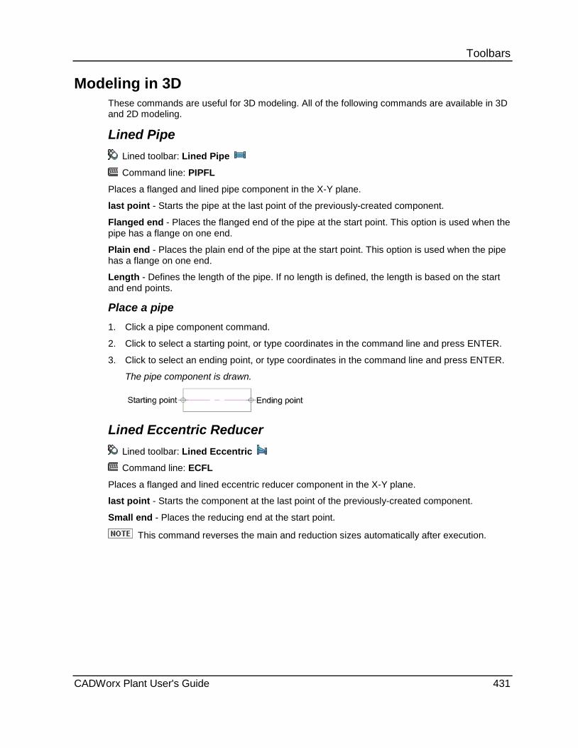
Toolbars
Modeling in 3D These commands are useful for 3D modeling. All of the following commands are available in 3D and 2D modeling.
Lined Pipe Lined toolbar: Lined Pipe
Command line: PIPFL
Places a flanged and lined pipe component in the X-Y plane.
last point - Starts the pipe at the last point of the previously-created component.
Flanged end - Places the flanged end of the pipe at the start point. This option is used when the pipe has a flange on one end.
Plain end - Places the plain end of the pipe at the start point. This option is used when the pipe has a flange on one end.
Length - Defines the length of the pipe. If no length is defined, the length is based on the start and end points.
Place a pipe 1. Click a pipe component command.
2. Click to select a starting point, or type coordinates in the command line and press ENTER.
3. Click to select an ending point, or type coordinates in the command line and press ENTER.
The pipe component is drawn.
Lined Eccentric Reducer Lined toolbar: Lined Eccentric
Command line: ECFL
Places a flanged and lined eccentric reducer component in the X-Y plane.
last point - Starts the component at the last point of the previously-created component.
Small end - Places the reducing end at the start point.
This command reverses the main and reduction sizes automatically after execution.
CADWorx Plant User's Guide 431

Toolbars Place an eccentric reducer 1. Click an eccentric reducer component command.
2. Pick a starting point for the large end, such as at the end of a pipe.
or
Select Small end, and press ENTER.
3. Click in the direction of the other end of the reducer.
4. To place the flat side in the X-Y plane, click in the direction of the flat side.
or
To place the flat side in the Z direction, select Up or Down.
The reducer component is drawn.
Lined Wye Plan Lined toolbar: Lined Wye Plan
Command line: YFL
Places a flanged and lined wye in the X-Y plane.
last point - Starts the component at the last point of the previously-created component.
Middle - Places the wye at the centerline intersection of the main and the branches of the wye.
Branch - Places the branch of the wye at the start point.
otherEnd - Places the component at the other end of the start point.
Place a plan wye 1. Click a plan wye command.
2. Click to select a starting point, such as at the end of a pipe.
3. Click in the direction of the wye.
The wye component is drawn.
432 CADWorx Plant User's Guide
Toolbars
Modeling in 2D Commands are designed for plotting in 2D. The views in these commands appear this way only in a 2D drawing.
Lined Wye Side Lined toolbar: Lined Wye Side
Command line: HYFL
Places a flanged and lined wye on the X-Y plane with the branches normal to the X-Y plane. This command is typically used with pipe that is on the X-Y plane.
last point - Starts the component at the last point of the previously-created component.
Middle - Places the wye at the centerline intersection of the main and branches of the wye.
Place a side wye 1. Click a side wye command.
2. Click to select a starting point, such as at the end of a pipe.
3. Click in the direction of the wye main.
The wye component is drawn.
Lined Wye Vert Lined toolbar: Lined Wye Vert
Command line: VYFL
Places a flanged and lined wye normal to the X-Y plane with the branches also normal to the X-Y plane. This command is typically used with pipe that is normal to the X-Y plane.
last point - Starts the component at the last point of the previously-created component.
Middle - Places the wye at the centerline intersection of the main and branches of the wye.
Place a vertical wye 1. Click a vertical wye command.
2. Click to select a starting point, such as at the end of a pipe.
3. Click in the direction of the wye branches.
The wye component is drawn.
CADWorx Plant User's Guide 433

Toolbars
Fiberglass Plant menu: Toolbars > Fiberglass
The commands on the Fiberglass toolbar can be used for modeling in 3D or 2D mode depending on how you define the drawing mode. For more information, see 3D Modeling versus 2D Modeling (on page 370).
Command Name Command Line
Pipe - Places a fiberglass pipe component. For more information, see Fiberglass Pipe (on page 437).
PIPF
FRP Bell 90 Ell Plan - Places a 90 degree threaded/socket elbow in the X-Y plane. For more information, see Plan Threaded/Socket 90 Degree Elbow (on page 437).
90S
FRP Bell 45 Ell Plan - Places a 45 degree threaded/socket elbow in the X-Y plane. For more information, see Threaded/Socket 45 Degree Elbow Plan (on page 438).
45S
FRP Bell Tee Plan - Places a straight threaded/socket tee in the X-Y plane. For more information, see Threaded/Socket Straight Tee Plan (on page 439).
TESS
FRP Bell Conc w/Hub - Places a threaded/socket concentric reducer component in the X-Y plane. For more information, see Threaded/Socket Concentric Reducer (on page 439).
SWGCS
FRP Bell Ecc w/Hub - Places an eccentric threaded/socket reducer component in the X-Y plane. For more information, see Threaded/Socket Eccentric Reducer (on page 440).
SWGES
FRP Bell Cross Plan - Places a four-way threaded/socket straight cross in the X-Y plane. For more information, see Threaded/Socket Straight Cross Plan (on page 440).
CRSS
FRP Bell Lateral Plan - Places a 45 degree threaded/socket lateral in the X-Y plane. For more information, see Threaded/Socket Lateral Plan (on page 441).
LATS
FRP Bell Full Clpg Plan - Places a coupling in the X-Y plane. For more information, see Coupling (on page 441).
CPS
FRP Cap - Places a threaded/socket pipe cap in the X-Y plane. For more information, see Threaded/Socket Cap (on page 441).
CAPS
434 CADWorx Plant User's Guide
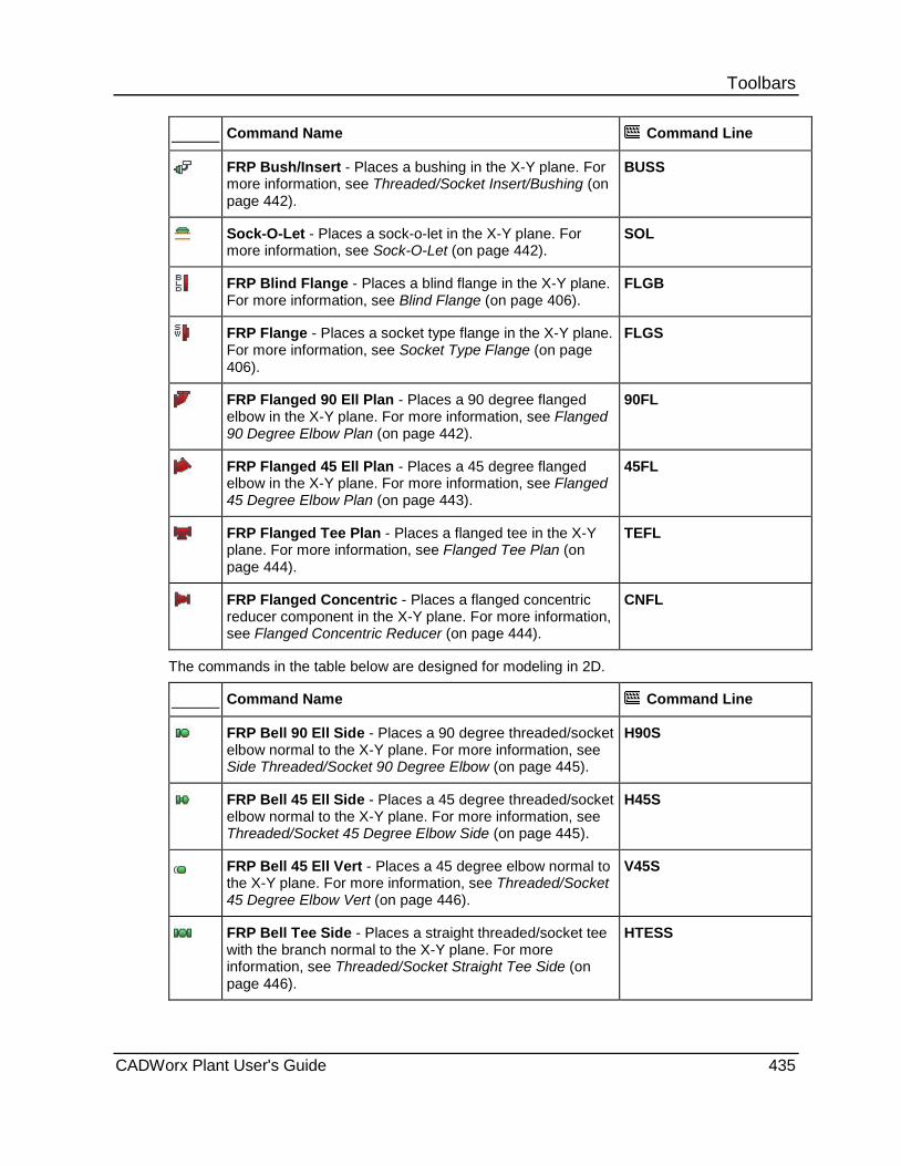
Toolbars Command Name Command Line
FRP Bush/Insert - Places a bushing in the X-Y plane. For more information, see Threaded/Socket Insert/Bushing (on page 442).
BUSS
Sock-O-Let - Places a sock-o-let in the X-Y plane. For more information, see Sock-O-Let (on page 442).
SOL
FRP Blind Flange - Places a blind flange in the X-Y plane. For more information, see Blind Flange (on page 406).
FLGB
FRP Flange - Places a socket type flange in the X-Y plane. For more information, see Socket Type Flange (on page 406).
FLGS
FRP Flanged 90 Ell Plan - Places a 90 degree flanged elbow in the X-Y plane. For more information, see Flanged 90 Degree Elbow Plan (on page 442).
90FL
FRP Flanged 45 Ell Plan - Places a 45 degree flanged elbow in the X-Y plane. For more information, see Flanged 45 Degree Elbow Plan (on page 443).
45FL
FRP Flanged Tee Plan - Places a flanged tee in the X-Y plane. For more information, see Flanged Tee Plan (on page 444).
TEFL
FRP Flanged Concentric - Places a flanged concentric reducer component in the X-Y plane. For more information, see Flanged Concentric Reducer (on page 444).
CNFL
The commands in the table below are designed for modeling in 2D.
Command Name Command Line
FRP Bell 90 Ell Side - Places a 90 degree threaded/socket elbow normal to the X-Y plane. For more information, see Side Threaded/Socket 90 Degree Elbow (on page 445).
H90S
FRP Bell 45 Ell Side - Places a 45 degree threaded/socket elbow normal to the X-Y plane. For more information, see Threaded/Socket 45 Degree Elbow Side (on page 445).
H45S
FRP Bell 45 Ell Vert - Places a 45 degree elbow normal to the X-Y plane. For more information, see Threaded/Socket 45 Degree Elbow Vert (on page 446).
V45S
FRP Bell Tee Side - Places a straight threaded/socket tee with the branch normal to the X-Y plane. For more information, see Threaded/Socket Straight Tee Side (on page 446).
HTESS
CADWorx Plant User's Guide 435
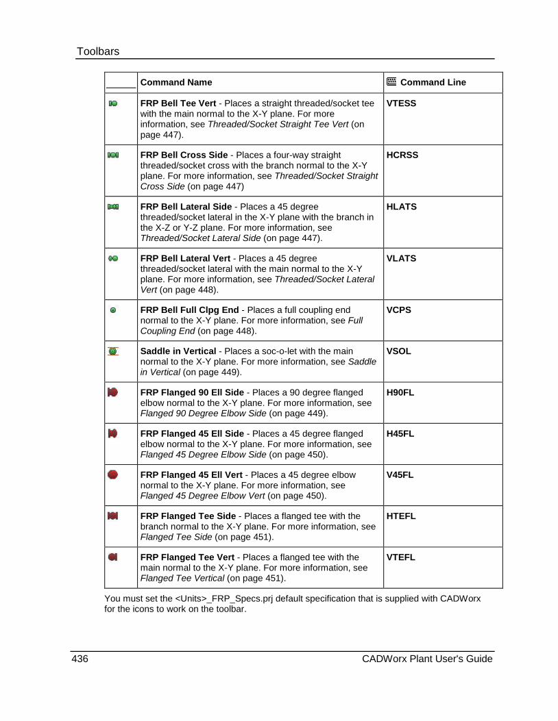
Toolbars Command Name Command Line
FRP Bell Tee Vert - Places a straight threaded/socket tee with the main normal to the X-Y plane. For more information, see Threaded/Socket Straight Tee Vert (on page 447).
VTESS
FRP Bell Cross Side - Places a four-way straight threaded/socket cross with the branch normal to the X-Y plane. For more information, see Threaded/Socket Straight Cross Side (on page 447)
HCRSS
FRP Bell Lateral Side - Places a 45 degree threaded/socket lateral in the X-Y plane with the branch in the X-Z or Y-Z plane. For more information, see Threaded/Socket Lateral Side (on page 447).
HLATS
FRP Bell Lateral Vert - Places a 45 degree threaded/socket lateral with the main normal to the X-Y plane. For more information, see Threaded/Socket Lateral Vert (on page 448).
VLATS
FRP Bell Full Clpg End - Places a full coupling end normal to the X-Y plane. For more information, see Full Coupling End (on page 448).
VCPS
Saddle in Vertical - Places a soc-o-let with the main normal to the X-Y plane. For more information, see Saddle in Vertical (on page 449).
VSOL
FRP Flanged 90 Ell Side - Places a 90 degree flanged elbow normal to the X-Y plane. For more information, see Flanged 90 Degree Elbow Side (on page 449).
H90FL
FRP Flanged 45 Ell Side - Places a 45 degree flanged elbow normal to the X-Y plane. For more information, see Flanged 45 Degree Elbow Side (on page 450).
H45FL
FRP Flanged 45 Ell Vert - Places a 45 degree elbow normal to the X-Y plane. For more information, see Flanged 45 Degree Elbow Vert (on page 450).
V45FL
FRP Flanged Tee Side - Places a flanged tee with the branch normal to the X-Y plane. For more information, see Flanged Tee Side (on page 451).
HTEFL
FRP Flanged Tee Vert - Places a flanged tee with the main normal to the X-Y plane. For more information, see Flanged Tee Vertical (on page 451).
VTEFL
You must set the <Units>_FRP_Specs.prj default specification that is supplied with CADWorx for the icons to work on the toolbar.
436 CADWorx Plant User's Guide
Toolbars
Modeling in 3D These commands are useful for 3D modeling. All of the following commands are available in 3D and 2D modeling.
Fiberglass Pipe Fiberglass toolbar: Pipe Command line: PIPF
Places a pipe component in the X-Y plane. Ends - Specifies the end options for the starting and ending of the pipe. Threaded Bevel Plain last point - Starts the pipe at the last point of the previously-created component. Center - Places the pipe along the center of the pipe, as defined along the Z-axis. TOP - Places the pipe along the top of the pipe, as defined along the Z-axis. BOP - Places the pipe along the bottom of the pipe, as defined along the Z-axis. Right - Places the pipe along the right side of the pipe, as defined along the Z-axis. Left - Places the pipe along the left side of the pipe, as defined along the Z-axis.
Place a fiberglass pipe 1. Click a pipe component command. 2. Click to select a starting point, or type the required coordinates in the command line, and
press ENTER. 3. Click to select an ending point, or type the required coordinates in the command line, and
press ENTER. 4. If prompted for an end type, type the required end type on the command line, and press
ENTER. The pipe component is drawn.
Plan Threaded/Socket 90 Degree Elbow Fiberglass toolbar: FRP Bell 90 Ell Plan
Command line: 90S
Places a 90 degree threaded/socket elbow in the X-Y plane.
last point - Starts the component at the last point of the previously-created component.
Start - Places the start point of the component at the default.
Corner - Places the component at the corner of two pipes.
otherEnd - Places the start point of the component on the other end.
CADWorx Plant User's Guide 437
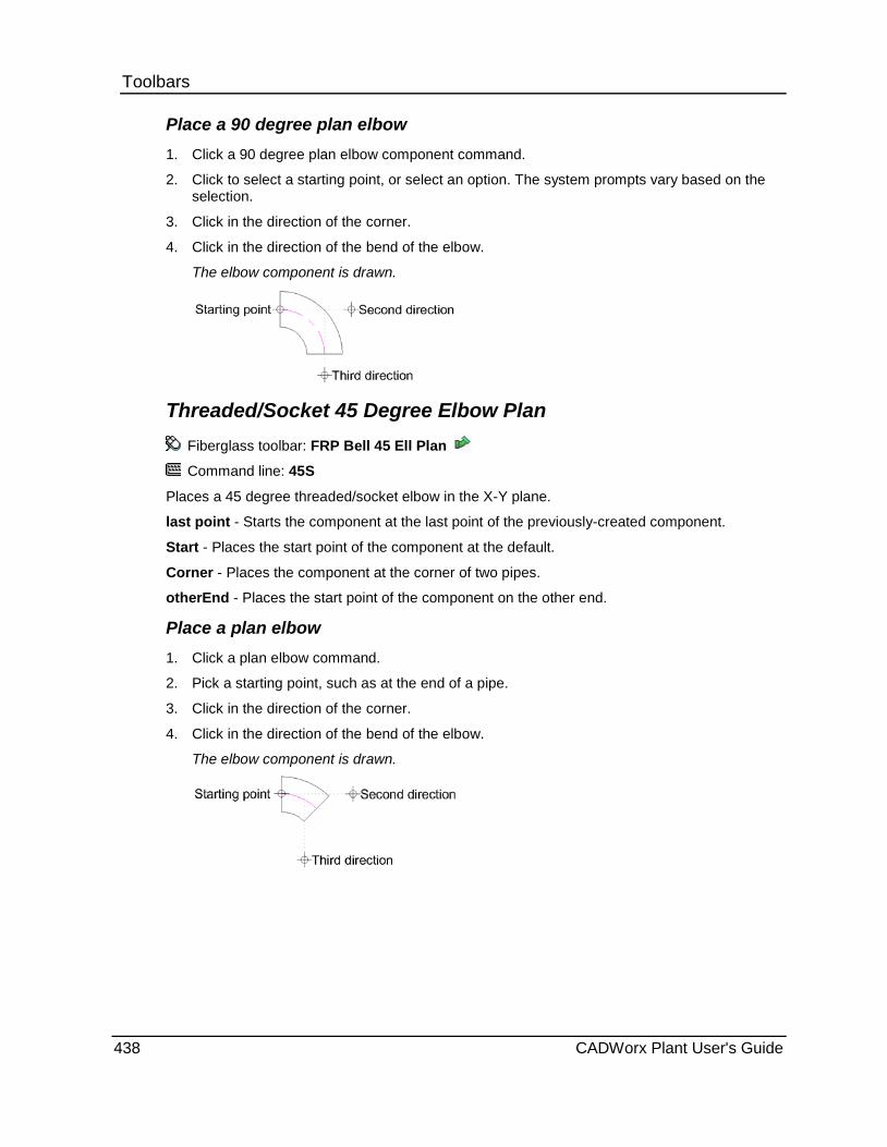
Toolbars Place a 90 degree plan elbow 1. Click a 90 degree plan elbow component command.
2. Click to select a starting point, or select an option. The system prompts vary based on the selection.
3. Click in the direction of the corner.
4. Click in the direction of the bend of the elbow.
The elbow component is drawn.
Threaded/Socket 45 Degree Elbow Plan Fiberglass toolbar: FRP Bell 45 Ell Plan
Command line: 45S
Places a 45 degree threaded/socket elbow in the X-Y plane.
last point - Starts the component at the last point of the previously-created component.
Start - Places the start point of the component at the default.
Corner - Places the component at the corner of two pipes.
otherEnd - Places the start point of the component on the other end.
Place a plan elbow 1. Click a plan elbow command.
2. Pick a starting point, such as at the end of a pipe.
3. Click in the direction of the corner.
4. Click in the direction of the bend of the elbow.
The elbow component is drawn.
438 CADWorx Plant User's Guide
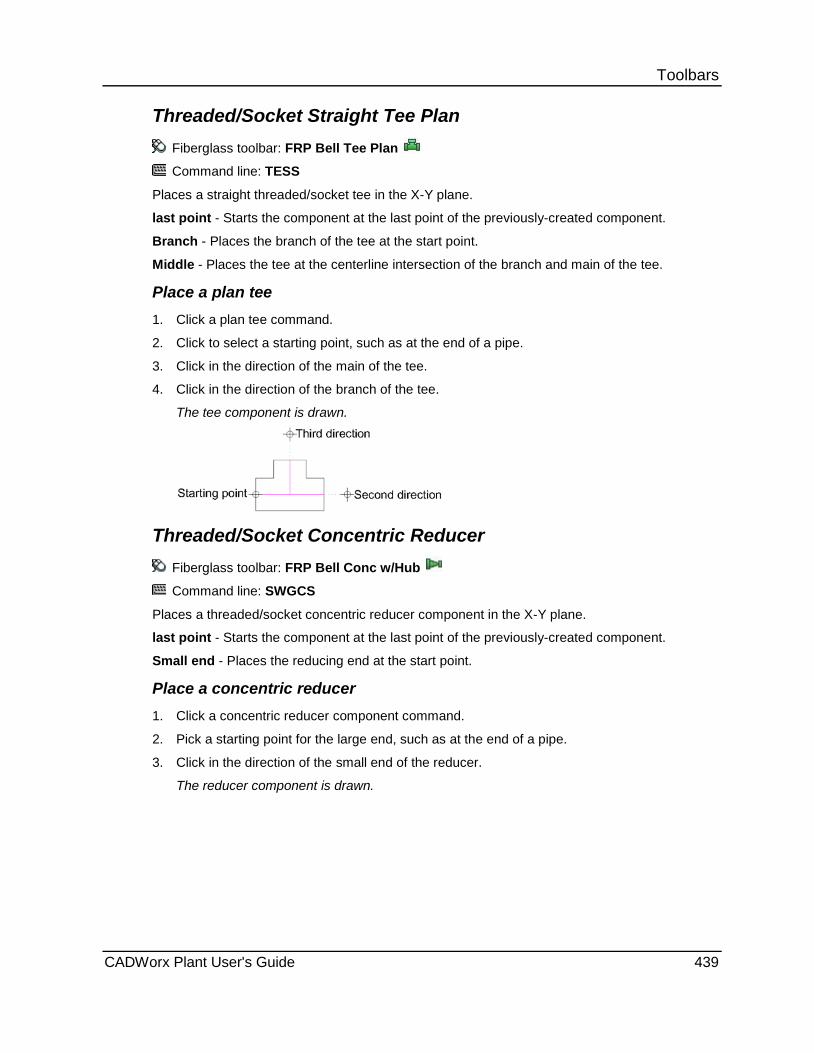
Toolbars Threaded/Socket Straight Tee Plan
Fiberglass toolbar: FRP Bell Tee Plan
Command line: TESS
Places a straight threaded/socket tee in the X-Y plane.
last point - Starts the component at the last point of the previously-created component.
Branch - Places the branch of the tee at the start point.
Middle - Places the tee at the centerline intersection of the branch and main of the tee.
Place a plan tee 1. Click a plan tee command.
2. Click to select a starting point, such as at the end of a pipe.
3. Click in the direction of the main of the tee.
4. Click in the direction of the branch of the tee.
The tee component is drawn.
Threaded/Socket Concentric Reducer Fiberglass toolbar: FRP Bell Conc w/Hub
Command line: SWGCS
Places a threaded/socket concentric reducer component in the X-Y plane.
last point - Starts the component at the last point of the previously-created component.
Small end - Places the reducing end at the start point.
Place a concentric reducer 1. Click a concentric reducer component command.
2. Pick a starting point for the large end, such as at the end of a pipe.
3. Click in the direction of the small end of the reducer.
The reducer component is drawn.
CADWorx Plant User's Guide 439

Toolbars Threaded/Socket Eccentric Reducer
Fiberglass toolbar: FRP Bell Ecc w/Hub
Command line: SWGES
Places an eccentric threaded/socket reducer component in the X-Y plane.
last point - Starts the component at the last point of the previously-created component.
Small end - Places the reducing end at the start point.
Up - Places the flat side of the reducer in the positive Z direction.
Down - Places the flat side of the reducer in the negative Z direction.
Place an eccentric reducer 1. Click an eccentric reducer component command. 2. Pick a starting point for the large end, such as at the end of a pipe.
or Select Small end, and press ENTER.
3. Click in the direction of the other end of the reducer. 4. To place the flat side in the X-Y plane, click in the direction of the flat side.
or To place the flat side in the Z direction, select Up or Down. The reducer component is drawn.
Threaded/Socket Straight Cross Plan Fiberglass toolbar: FRP Bell Cross Plan
Command line: CRSS
Places a four-way threaded/socket straight cross in the X-Y plane.
last point - Starts the component at the last point of the previously-created component.
Middle - Places the cross at the centerline intersection of the cross.
Branch - Places the branch of the cross at the start point.
Place a plan cross 1. Click a four-way straight cross command.
2. Click to select a starting point, such as at the end of a pipe.
3. Click in the direction of the cross.
The cross component is drawn.
440 CADWorx Plant User's Guide

Toolbars Threaded/Socket Lateral Plan
Fiberglass toolbar: FRP Bell Lateral Plan
Command line: LATS
Places a 45 degree threaded/socket lateral in the X-Y plane.
last point - Starts the component at the last point of the previously-created component.
Start - Places the start point of the component at the default.
Middle - Places the lateral at the centerline intersection of the branch and main.
otherEnd - Places the start point of the component on the other end.
Branch - Places the branch of the cross at the start point.
Place a plan lateral 1. Click a plan lateral command. 2. Click to select a starting point, such as at the end of a pipe. 3. Click in the direction of the main of the lateral. 4. Click in the direction of the branch of the lateral.
The lateral component is drawn.
Coupling
Fiberglass toolbar: FRP Bell Full Clpg Plan Victaulic toolbar: Victaulic Coupling Command line: CPS
Places a coupling in the X-Y plane.
Place a coupling 1. Click a coupling command. 2. Click to select a starting point, such as at the end of a pipe. 3. Click in the direction of the coupling.
The coupling component is drawn.
Threaded/Socket Cap Fiberglass toolbar: FRP Cap
Command line: CAPS
Places a threaded/socket pipe cap in the X-Y plane.
last point - Starts the component at the last point of the previously-created component.
Cap end - Places the top of the cap at the start point.
CADWorx Plant User's Guide 441
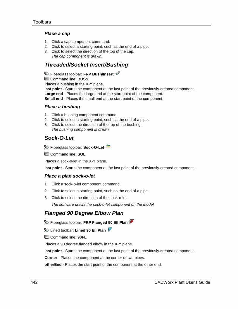
Toolbars Place a cap 1. Click a cap component command. 2. Click to select a starting point, such as the end of a pipe. 3. Click to select the direction of the top of the cap.
The cap component is drawn.
Threaded/Socket Insert/Bushing Fiberglass toolbar: FRP Bush/Insert Command line: BUSS
Places a bushing in the X-Y plane. last point - Starts the component at the last point of the previously-created component. Large end - Places the large end at the start point of the component. Small end - Places the small end at the start point of the component.
Place a bushing 1. Click a bushing component command. 2. Click to select a starting point, such as the end of a pipe. 3. Click to select the direction of the top of the bushing.
The bushing component is drawn.
Sock-O-Let Fiberglass toolbar: Sock-O-Let
Command line: SOL
Places a sock-o-let in the X-Y plane.
last point - Starts the component at the last point of the previously-created component.
Place a plan sock-o-let 1. Click a sock-o-let component command.
2. Click to select a starting point, such as the end of a pipe.
3. Click to select the direction of the sock-o-let.
The software draws the sock-o-let component on the model.
Flanged 90 Degree Elbow Plan Fiberglass toolbar: FRP Flanged 90 Ell Plan
Lined toolbar: Lined 90 Ell Plan
Command line: 90FL
Places a 90 degree flanged elbow in the X-Y plane.
last point - Starts the component at the last point of the previously-created component.
Corner - Places the component at the corner of two pipes.
otherEnd - Places the start point of the component at the other end.
442 CADWorx Plant User's Guide
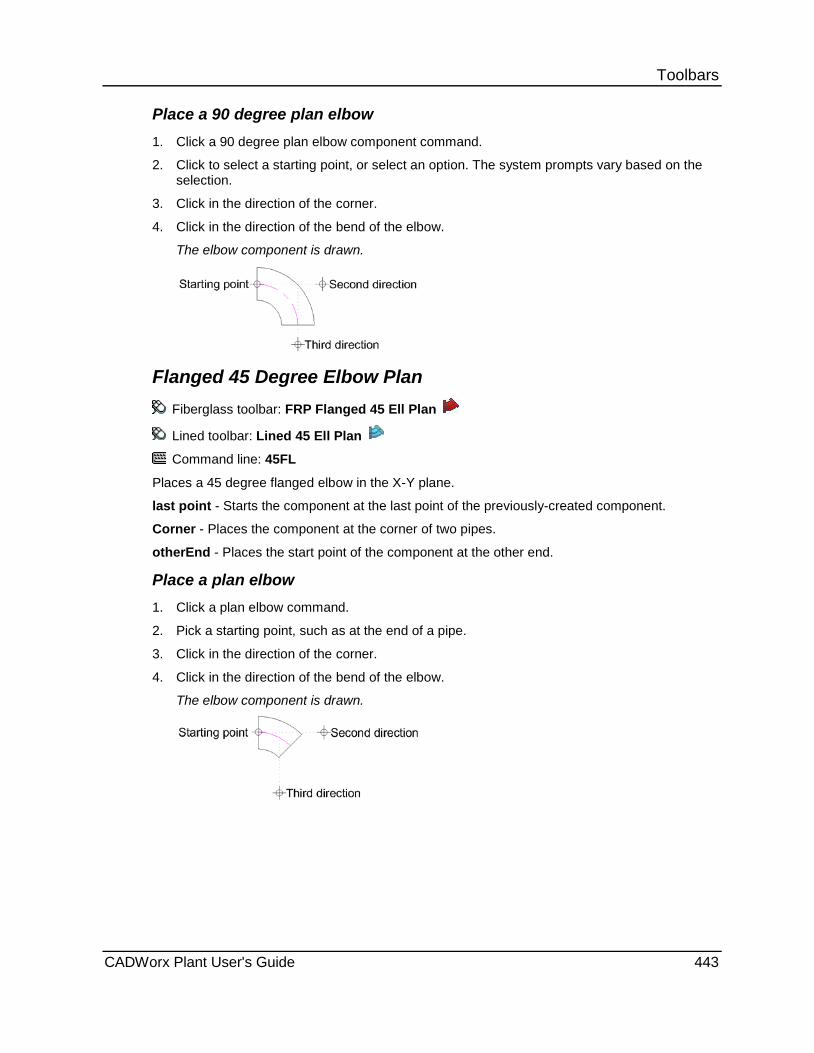
Toolbars Place a 90 degree plan elbow 1. Click a 90 degree plan elbow component command.
2. Click to select a starting point, or select an option. The system prompts vary based on the selection.
3. Click in the direction of the corner.
4. Click in the direction of the bend of the elbow.
The elbow component is drawn.
Flanged 45 Degree Elbow Plan Fiberglass toolbar: FRP Flanged 45 Ell Plan
Lined toolbar: Lined 45 Ell Plan
Command line: 45FL
Places a 45 degree flanged elbow in the X-Y plane.
last point - Starts the component at the last point of the previously-created component.
Corner - Places the component at the corner of two pipes.
otherEnd - Places the start point of the component at the other end.
Place a plan elbow 1. Click a plan elbow command.
2. Pick a starting point, such as at the end of a pipe.
3. Click in the direction of the corner.
4. Click in the direction of the bend of the elbow.
The elbow component is drawn.
CADWorx Plant User's Guide 443

Toolbars Flanged Tee Plan
Fiberglass toolbar: FRP Flanged Tee Plan
Victaulic toolbar: Plan Strainer
Lined toolbar: Lined Tee Plan
Command line: TEFL
Places a flanged tee or strainer in the X-Y plane.
last point - Starts the component at the last point of the previously-created component.
Middle - Places the component at the centerline intersection of the main and the branches of the component.
Branch - places the start point at the branch of the component.
Place a plan flanged tee 1. Click a plan flanged tee command.
2. Click to select a starting point, such as at the end of a pipe.
3. Click in the direction of the main of the tee.
4. Click in the direction of the branch of the tee.
The component is drawn.
Flanged Concentric Reducer
Fiberglass toolbar: FRP Flanged Concentric
Lined toolbar: Lined Concentric
Command line: CNFL
Places a flanged concentric reducer component in the X-Y plane.
last point - Starts the component at the last point of the previously-created component.
Small end - Places the reducing end at the start point.
Large end - Places the non-reducing end at the start point.
This command reverses the main and reduction sizes automatically after execution.
Place a concentric reducer 1. Click a concentric reducer component command.
2. Pick a starting point for the large end, such as at the end of a pipe.
3. Click in the direction of the small end of the reducer.
The reducer component is drawn.
444 CADWorx Plant User's Guide

Toolbars
Modeling in 2D Commands are designed for plotting in 2D. The views in these commands appear this way only in a 2D drawing.
Side Threaded/Socket 90 Degree Elbow Fiberglass toolbar: FRP Bell 90 Ell Side Command line: H90S
Places a 90 degree threaded/socket elbow normal to the X-Y plane. last point - Starts the component at the last point of the previously-created component. Up - Places the elbow bend in the positive Z direction. Down - Places the elbow bend in the negative Z direction.
Place a side or vertical elbow 1. Click a side or vertical elbow component command. 2. Click to select a starting point, such as at the end of a pipe. 3. Click in the direction of the corner. 4. Select Up or Down.
The elbow component is drawn.
Threaded/Socket 45 Degree Elbow Side Fiberglass toolbar: FRP Bell 45 Ell Side
Command line: H45S
Places a 45 degree threaded/socket elbow normal to the X-Y plane. Use this command when the previous or next run is horizontal to the X-Y plane.
last point - Starts the component at the last point of the previously-created component.
Up - Places the elbow bend in the positive Z direction.
Down - Places the elbow bend in the negative Z direction.
Place a side or vertical elbow 1. Click a side or vertical elbow component command.
2. Click to select a starting point, such as at the end of a pipe.
3. Click in the direction of the corner.
4. Select Up or Down.
The elbow component is drawn.
CADWorx Plant User's Guide 445
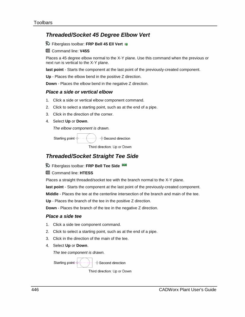
Toolbars Threaded/Socket 45 Degree Elbow Vert
Fiberglass toolbar: FRP Bell 45 Ell Vert
Command line: V45S
Places a 45 degree elbow normal to the X-Y plane. Use this command when the previous or next run is vertical to the X-Y plane.
last point - Starts the component at the last point of the previously-created component.
Up - Places the elbow bend in the positive Z direction.
Down - Places the elbow bend in the negative Z direction.
Place a side or vertical elbow 1. Click a side or vertical elbow component command.
2. Click to select a starting point, such as at the end of a pipe.
3. Click in the direction of the corner.
4. Select Up or Down.
The elbow component is drawn.
Threaded/Socket Straight Tee Side Fiberglass toolbar: FRP Bell Tee Side
Command line: HTESS
Places a straight threaded/socket tee with the branch normal to the X-Y plane.
last point - Starts the component at the last point of the previously-created component.
Middle - Places the tee at the centerline intersection of the branch and main of the tee.
Up - Places the branch of the tee in the positive Z direction.
Down - Places the branch of the tee in the negative Z direction.
Place a side tee 1. Click a side tee component command.
2. Click to select a starting point, such as at the end of a pipe.
3. Click in the direction of the main of the tee.
4. Select Up or Down.
The tee component is drawn.
446 CADWorx Plant User's Guide
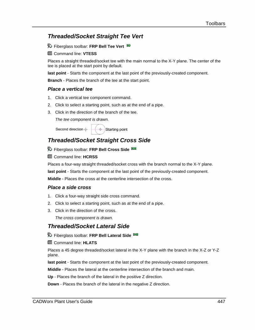
Toolbars Threaded/Socket Straight Tee Vert
Fiberglass toolbar: FRP Bell Tee Vert
Command line: VTESS
Places a straight threaded/socket tee with the main normal to the X-Y plane. The center of the tee is placed at the start point by default.
last point - Starts the component at the last point of the previously-created component.
Branch - Places the branch of the tee at the start point.
Place a vertical tee 1. Click a vertical tee component command.
2. Click to select a starting point, such as at the end of a pipe.
3. Click in the direction of the branch of the tee.
The tee component is drawn.
Threaded/Socket Straight Cross Side
Fiberglass toolbar: FRP Bell Cross Side
Command line: HCRSS
Places a four-way straight threaded/socket cross with the branch normal to the X-Y plane.
last point - Starts the component at the last point of the previously-created component.
Middle - Places the cross at the centerline intersection of the cross.
Place a side cross 1. Click a four-way straight side cross command.
2. Click to select a starting point, such as at the end of a pipe.
3. Click in the direction of the cross.
The cross component is drawn.
Threaded/Socket Lateral Side Fiberglass toolbar: FRP Bell Lateral Side
Command line: HLATS
Places a 45 degree threaded/socket lateral in the X-Y plane with the branch in the X-Z or Y-Z plane.
last point - Starts the component at the last point of the previously-created component.
Middle - Places the lateral at the centerline intersection of the branch and main.
Up - Places the branch of the lateral in the positive Z direction.
Down - Places the branch of the lateral in the negative Z direction.
CADWorx Plant User's Guide 447
Toolbars Place a side lateral 1. Click a side lateral component command.
2. Click to select a starting point, such as at the end of a pipe.
3. Click in the direction of the main of the lateral.
4. Select Up or Down.
The lateral component is drawn.
Threaded/Socket Lateral Vert Fiberglass toolbar: FRP Bell Lateral Vert
Command line: VLATS
Places a 45 degree threaded/socket lateral with the main normal to the X-Y plane. The center of the lateral is placed at the start point by default.
last point - Starts the component at the last point of the previously-created component.
Up - Places the branch of the lateral in the positive Z direction.
Down - Places the branch of the lateral in the negative Z direction.
Place a vertical lateral 1. Click a vertical lateral component command.
2. Click to select a starting point, such as at the end of a pipe.
3. Click in the direction of the branch of the lateral.
4. Select Up or Down.
The lateral component is drawn.
Full Coupling End Fiberglass toolbar: FRP Bell Full Clpg End
Command line: VCPS
Places a full coupling end normal to the X-Y plane.
last point - Starts the component at the last point of the previously-created component.
Up - Places the coupling in the positive Z direction.
Down - Places the coupling in the negative Z direction.
Place a coupling end 1. Click a coupling end component command.
2. Click to select a starting point, such as the end of a pipe.
3. Click to select the direction of the top of the coupling.
The coupling component is drawn.
448 CADWorx Plant User's Guide

Toolbars Saddle in Vertical
Fiberglass toolbar: Saddle in Vertical
Command line: VSOL
Places a soc-o-let with the main normal to the X-Y plane. The center of the lateral is placed at the start point by default.
last point - Starts the component at the last point of the previously-created component.
Up - Places the top of the soc-o-let in the positive Z direction.
Down - Places the top of the soc-o-let in the negative Z direction.
Place a vertical soc-o-let 1. Click a vertical soc-o-let component command.
2. Click to select a starting point, such as at the end of a pipe.
3. Click in the direction of the branch of the lateral.
4. Select Up or Down.
The soc-o-let component is drawn.
Flanged 90 Degree Elbow Side Fiberglass toolbar: FRP Flanged 90 Ell Side
Lined toolbar: Lined 90 Ell Side
Command line: H90FL
Places a 90 degree flanged elbow normal to the X-Y plane.
last point - Starts the component at the last point of the previously-created component.
Up - Places the elbow bend in the positive Z direction.
Down - Places the elbow bend in the negative Z direction.
Place a side or vertical elbow 1. Click a side or vertical elbow component command.
2. Click to select a starting point, such as at the end of a pipe.
3. Click in the direction of the corner.
4. Select Up or Down.
The elbow component is drawn.
CADWorx Plant User's Guide 449

Toolbars Flanged 45 Degree Elbow Side
Fiberglass toolbar: FRP Flanged 45 Ell Side
Lined toolbar: Lined 45 Ell Side
Command line: H45FL
Places a 45 degree flanged elbow normal to the X-Y plane. Use this command when the previous or next run is horizontal to the X-Y plane.
last point - Starts the component at the last point of the previously-created component.
Up - Places the elbow bend in the positive Z direction.
Down - Places the elbow bend in the negative Z direction.
Place a side or vertical elbow 1. Click a side or vertical elbow component command.
2. Click to select a starting point, such as at the end of a pipe.
3. Click in the direction of the corner.
4. Select Up or Down.
The elbow component is drawn.
Flanged 45 Degree Elbow Vert
Fiberglass toolbar: FRP Flanged 45 Ell Vert Lined toolbar: Lined 45 Ell Vert Command line: V45FL
Places a 45 degree flanged elbow normal to the X-Y plane. Use this command when the previous or next run is vertical to the X-Y plane. last point - Starts the component at the last point of the previously-created component. Up - Places the elbow bend in the positive Z direction. Down - Places the elbow bend in the negative Z direction.
Place a side or vertical elbow 1. Click a side or vertical elbow component command.
2. Click to select a starting point, such as at the end of a pipe.
3. Click in the direction of the corner.
4. Select Up or Down.
The elbow component is drawn.
450 CADWorx Plant User's Guide

Toolbars Flanged Tee Side
Fiberglass toolbar: FRP Flanged Tee Side
Victaulic toolbar: Side Strainer
Lined toolbar: Lined Tee Side
Command line: HTEFL
Places a flanged tee or strainer with the branch normal to the X-Y plane.
last point - Starts the component at the last point of the previously-created component.
Middle - Places the strainer at the centerline intersection of the branch and main of the tee.
Up - Places the branch of the tee in the positive Z direction.
Down - Places the branch of the tee in the negative Z direction.
Place a side flanged tee 1. Click a side flanged tee component command. 2. Click to select a starting point, such as at the end of a pipe. 3. Click in the direction of the main of the tee. 4. Select Up or Down.
The component is drawn.
Flanged Tee Vertical Fiberglass toolbar: FRP Flanged Tee Vert Victaulic toolbar: Vert Strainer Lined toolbar: Lined Tee Vert Command line: VTEFL
Places a flanged tee or strainer with the main normal to the X-Y plane. The center of the strainer is placed at the start point by default. last point - Starts the component at the last point of the previously-created component. Branch - Places the branch of the tee at the start point.
Place a vertical strainer 1. Click a vertical flanged tee component command.
2. Click to select a starting point, such as at the end of a pipe.
3. Click in the direction of the branch of the tee.
The component is drawn.
CADWorx Plant User's Guide 451

Toolbars
Sanitary Plant menu: Toolbars > Sanitary
The commands on the Sanitary toolbar can be used for modeling in 3D or 2D mode depending on how you define the drawing mode. For more information, see 3D Modeling versus 2D Modeling (on page 370).
Command Name Command Line
Sanitary Tubing - Places a butt-welded sanitary tubing component. For more information, see Pipe (on page 375).
PIPW
Sanitary 90 Ell Plan - Places a 90 degree elbow in the X-Y plane. For more information, see Sanitary 90 Ell Plan (on page 459).
90EN
Sanitary 90 Reducing Ell Plan - Places a 90 degree reducing elbow in the X-Y plane. For more information, see Sanitary 90 Reducing Ell Plan (on page 460).
90RE
Sanitary 45 Ell Plan - Places a 45 degree sanitary elbow in the X-Y plane. For more information, see Sanitary 45 Ell Plan (on page 460).
45EN
Sanitary Tee Plan - Places a straight sanitary tee in the X-Y plane. For more information, see Sanitary Tee Plan (on page 461).
TESE
Sanitary Reducing Tee Plan - Places a sanitary reducing tee in the X-Y plane. For more information, see Reducing Tee Plan (on page 461).
TERE
Sanitary Cross Plan - Places a four-way sanitary cross in the X-Y plane. For more information, see Cross Plan (on page 462).
CRSE
Sanitary Cross Reducing Plan - Places a four-way sanitary reducing cross in the X-Y plane. For more information, see Cross Reducing Plan (on page 462).
CRRE
Sanitary Lateral Plan - Places a 45 degree sanitary lateral in the X-Y plane. For more information, see Lateral Plan (on page 463).
LATE
Sanitary Lateral Reducing Plan - Places a 45 degree sanitary reducing lateral in the X-Y plane. For more information, see Sanitary Lateral Reducing Plan (on page 463).
LARE
Sanitary 22.5 Ell Plan - Places a 22.5 degree sanitary elbow in the X-Y plane. For more information, see Sanitary 22.5 Ell Plan (on page 464).
22EN
452 CADWorx Plant User's Guide

Toolbars Command Name Command Line
Sanitary 11.25 Ell Plan - Places an 11.25 degree sanitary elbow in the X-Y plane. For more information, see Sanitary 11.25 Ell Plan (on page 465).
11EN
Sanitary U-Bend Plan - Places a 180 degree u-bend in the X-Y plane. For more information, see Sanitary U-Bend Plan (on page 465).
UBEN
Sanitary Concentric - Places a sanitary concentric reducer component in the X-Y plane. For more information, see Sanitary Concentric (on page 466).
CONCE
Sanitary Eccentric - Places a sanitary eccentric reducer component in the X-Y plane. For more information, see Sanitary Eccentric (on page 466).
ECCE
Sanitary Stub - Places a sanitary stub coupling component in the X-Y plane. For more information, see Sanitary Stub (on page 467).
STUE
Sanitary Wye Plan - Places a sanitary wye in the X-Y plane. For more information, see Sanitary Wye Plan (on page 467).
YE
Sanitary Cap - Places a sanitary pipe cap in the X-Y plane. For more information, see Sanitary Cap (on page 468).
CAPE
Sanitary Nut/Coupling - Places a sanitary nut/coupling in the X-Y plane. For more information, see Sanitary Nut/Coupling (on page 468).
NUTE
Sanitary Gate Valve - Places a sanitary gate valve component in the X-Y plane. For more information, see Sanitary Gate Valve (on page 469).
GATE
Sanitary Ball Valve - Places a sanitary ball valve component in the X-Y plane. For more information, see Sanitary Ball Valve (on page 469).
BALE
Sanitary Globe Valve - Places a sanitary globe valve component in the X-Y plane. For more information, see Sanitary Globe Valve (on page 470).
GLBE
Sanitary Plug Valve - Places a sanitary plug valve component in the X-Y plane. For more information, see Sanitary Plug Valve (on page 470).
PLUE
Sanitary Check Valve - Places a sanitary check valve component in the X-Y plane. For more information, see Sanitary Check Valve (on page 471).
CHKE
Sanitary Butterfly Valve - Places a sanitary butterfly valve component in the X-Y plane. For more information, see Sanitary Butterfly Valve (on page 471).
BFYE
CADWorx Plant User's Guide 453
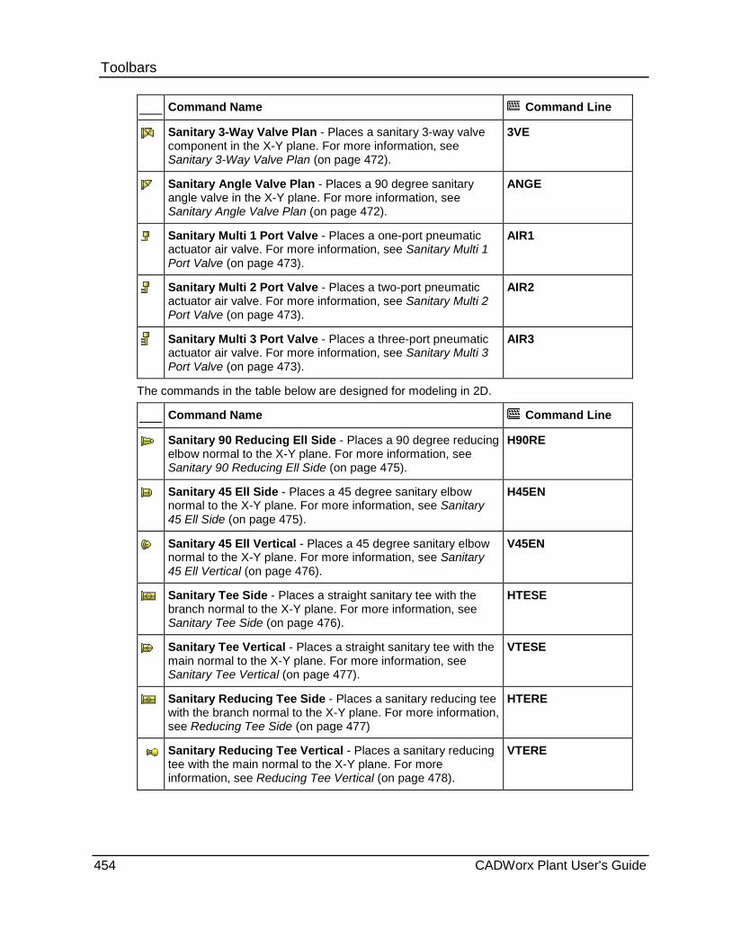
Toolbars Command Name Command Line
Sanitary 3-Way Valve Plan - Places a sanitary 3-way valve component in the X-Y plane. For more information, see Sanitary 3-Way Valve Plan (on page 472).
3VE
Sanitary Angle Valve Plan - Places a 90 degree sanitary angle valve in the X-Y plane. For more information, see Sanitary Angle Valve Plan (on page 472).
ANGE
Sanitary Multi 1 Port Valve - Places a one-port pneumatic actuator air valve. For more information, see Sanitary Multi 1 Port Valve (on page 473).
AIR1
Sanitary Multi 2 Port Valve - Places a two-port pneumatic actuator air valve. For more information, see Sanitary Multi 2 Port Valve (on page 473).
AIR2
Sanitary Multi 3 Port Valve - Places a three-port pneumatic actuator air valve. For more information, see Sanitary Multi 3 Port Valve (on page 473).
AIR3
The commands in the table below are designed for modeling in 2D.
Command Name Command Line
Sanitary 90 Reducing Ell Side - Places a 90 degree reducing elbow normal to the X-Y plane. For more information, see Sanitary 90 Reducing Ell Side (on page 475).
H90RE
Sanitary 45 Ell Side - Places a 45 degree sanitary elbow normal to the X-Y plane. For more information, see Sanitary 45 Ell Side (on page 475).
H45EN
Sanitary 45 Ell Vertical - Places a 45 degree sanitary elbow normal to the X-Y plane. For more information, see Sanitary 45 Ell Vertical (on page 476).
V45EN
Sanitary Tee Side - Places a straight sanitary tee with the branch normal to the X-Y plane. For more information, see Sanitary Tee Side (on page 476).
HTESE
Sanitary Tee Vertical - Places a straight sanitary tee with the main normal to the X-Y plane. For more information, see Sanitary Tee Vertical (on page 477).
VTESE
Sanitary Reducing Tee Side - Places a sanitary reducing tee with the branch normal to the X-Y plane. For more information, see Reducing Tee Side (on page 477)
HTERE
Sanitary Reducing Tee Vertical - Places a sanitary reducing tee with the main normal to the X-Y plane. For more information, see Reducing Tee Vertical (on page 478).
VTERE
454 CADWorx Plant User's Guide

Toolbars Command Name Command Line
Sanitary Cross Side - Places a four-way sanitary cross with the branches normal to the X-Y plane. For more information, see Cross Side (on page 478).
HCRSE
Sanitary Reducing Cross Side - Places a four-way sanitary reducing cross with the reducing branch normal to the X-Y plane. For more information, see Cross Reducing Side (on page 478).
HCRRE
Sanitary Cross Reducing Vertical - Places a four-way sanitary reducing cross with the main normal to the X-Y plane. For more information, see Cross Reducing Vertical (on page 479).
VCRRE
Sanitary Lateral Side - Places a 45 degree sanitary lateral in the X-Y plane with the branch in the X-Z or Y-Z plane. For more information, see Lateral Side (on page 479).
HLATE
Sanitary Lateral Vertical - Places a 45 degree sanitary lateral with the main normal to the X-Y plane. For more information, see Lateral Vertical (on page 480).
VLATE
Sanitary Lateral Reducing Side - Places a 45 degree sanitary reducing lateral in the X-Y plane with the branch in the X-Z or Y-Z plane. For more information, see Sanitary Lateral Reducing Side (on page 480).
HLARE
Sanitary Lateral Reducing Vertical -Places a 45 degree sanitary reducing lateral with the main normal to the X-Y plane. For more information, see Sanitary Lateral Reducing Vertical (on page 481).
VLARE
Sanitary 22.5 Ell Side - Places a 22.5 degree sanitary elbow normal to the X-Y plane when the previous or next run is horizontal to the X-Y plane. For more information, see Sanitary 22.5 Ell Side (on page 481).
H22EN
Sanitary 22.5 Ell Vertical - Places a 22.5 degree elbow normal to the X-Y plane when the previous or next run is vertical to the X-Y plane. For more information, see Sanitary 22.5 Ell Vertical (on page 482).
V22EN
Sanitary 11.25 Ell Side - Places an 11.25 degree sanitary elbow normal to the X-Y plane when the previous or next run is horizontal to the X-Y plane. For more information, see Sanitary 11.25 Ell Side (on page 482).
H11EN
Sanitary 11.25 Ell Vertical - Places an 11.25 degree elbow normal to the X-Y plane when the previous or next run is vertical to the X-Y plane. For more information, see Sanitary 11.25 Ell Vertical (on page 483).
V11EN
CADWorx Plant User's Guide 455
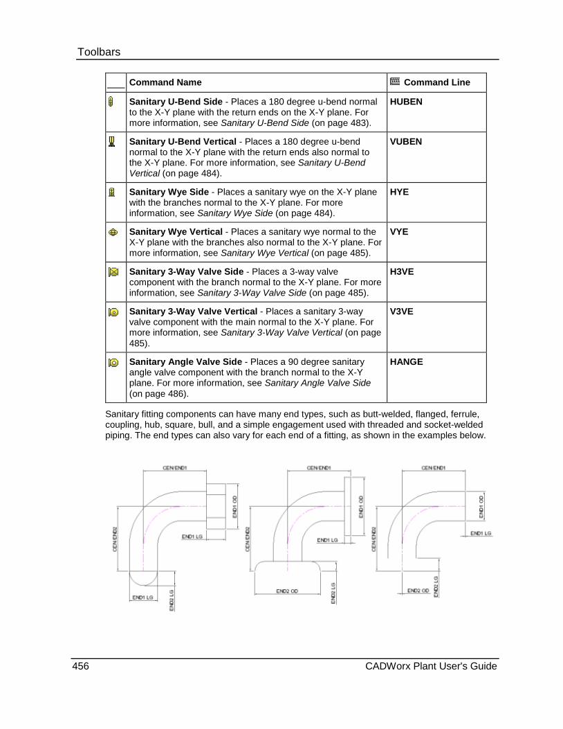
Toolbars Command Name Command Line
Sanitary U-Bend Side - Places a 180 degree u-bend normal to the X-Y plane with the return ends on the X-Y plane. For more information, see Sanitary U-Bend Side (on page 483).
HUBEN
Sanitary U-Bend Vertical - Places a 180 degree u-bend normal to the X-Y plane with the return ends also normal to the X-Y plane. For more information, see Sanitary U-Bend Vertical (on page 484).
VUBEN
Sanitary Wye Side - Places a sanitary wye on the X-Y plane with the branches normal to the X-Y plane. For more information, see Sanitary Wye Side (on page 484).
HYE
Sanitary Wye Vertical - Places a sanitary wye normal to the X-Y plane with the branches also normal to the X-Y plane. For more information, see Sanitary Wye Vertical (on page 485).
VYE
Sanitary 3-Way Valve Side - Places a 3-way valve component with the branch normal to the X-Y plane. For more information, see Sanitary 3-Way Valve Side (on page 485).
H3VE
Sanitary 3-Way Valve Vertical - Places a sanitary 3-way valve component with the main normal to the X-Y plane. For more information, see Sanitary 3-Way Valve Vertical (on page 485).
V3VE
Sanitary Angle Valve Side - Places a 90 degree sanitary angle valve component with the branch normal to the X-Y plane. For more information, see Sanitary Angle Valve Side (on page 486).
HANGE
Sanitary fitting components can have many end types, such as butt-welded, flanged, ferrule, coupling, hub, square, bull, and a simple engagement used with threaded and socket-welded piping. The end types can also vary for each end of a fitting, as shown in the examples below.
456 CADWorx Plant User's Guide
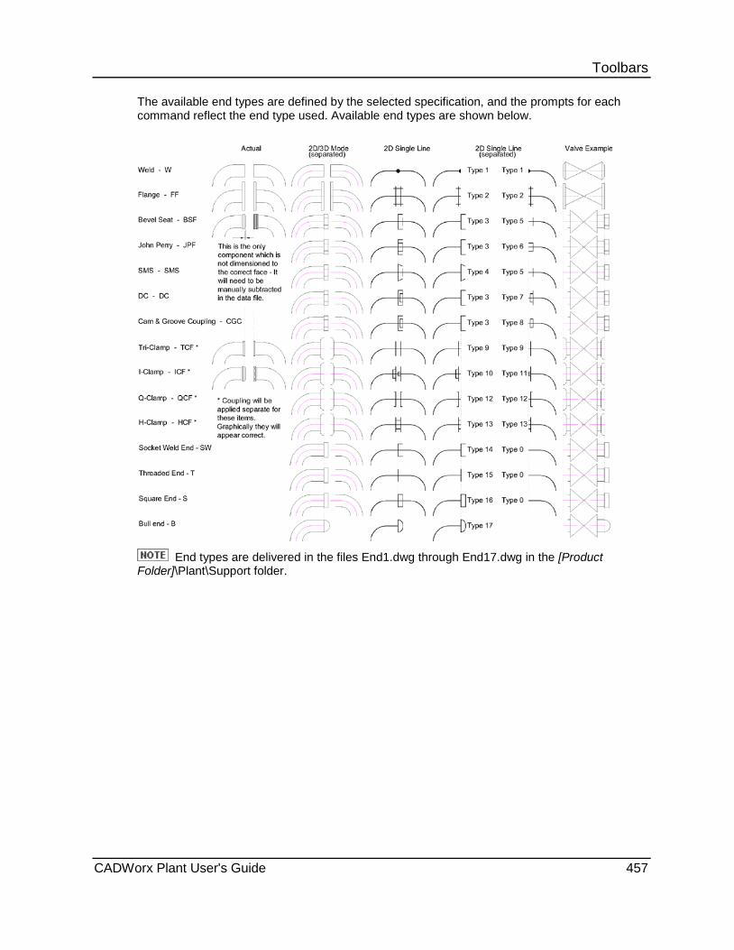
Toolbars The available end types are defined by the selected specification, and the prompts for each command reflect the end type used. Available end types are shown below.
End types are delivered in the files End1.dwg through End17.dwg in the [Product
Folder]\Plant\Support folder.
CADWorx Plant User's Guide 457
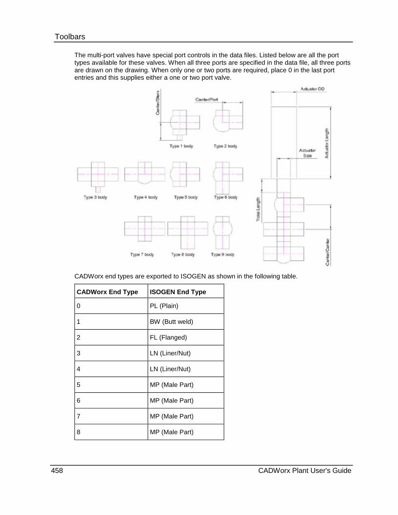
Toolbars The multi-port valves have special port controls in the data files. Listed below are all the port types available for these valves. When all three ports are specified in the data file, all three ports are drawn on the drawing. When only one or two ports are required, place 0 in the last port entries and this supplies either a one or two port valve.
CADWorx end types are exported to ISOGEN as shown in the following table.
CADWorx End Type ISOGEN End Type
0 PL (Plain)
1 BW (Butt weld)
2 FL (Flanged)
3 LN (Liner/Nut)
4 LN (Liner/Nut)
5 MP (Male Part)
6 MP (Male Part)
7 MP (Male Part)
8 MP (Male Part)
458 CADWorx Plant User's Guide

Toolbars 9 CL (Clamped)
10 CL (Clamped)
11 CL (Clamped)
12 CL (Clamped)
13 CL (Clamped)
14 SW (Socket Weld)
15 SC (Screwed)
Modeling in 3D These commands are useful for 3D modeling. All of the following commands are available in 3D and 2D modeling.
Sanitary 90 Ell Plan Sanitary toolbar: Sanitary 90 Ell Plan
Command line: 90EN
Places a 90 degree sanitary elbow in the X-Y plane.
last point - Starts the component at the last point of the previously-created component.
Corner - Places the component at the corner of two pipes.
otherEnd - Places the other end of the elbow at the start point.
The end type is defined by the current specification.
Place a 90 degree plan elbow 1. Click a 90 degree plan elbow component command.
2. Click to select a starting point, or select an option. The system prompts vary based on the selection.
3. Click in the direction of the corner.
4. Click in the direction of the bend of the elbow.
The elbow component is drawn.
CADWorx Plant User's Guide 459
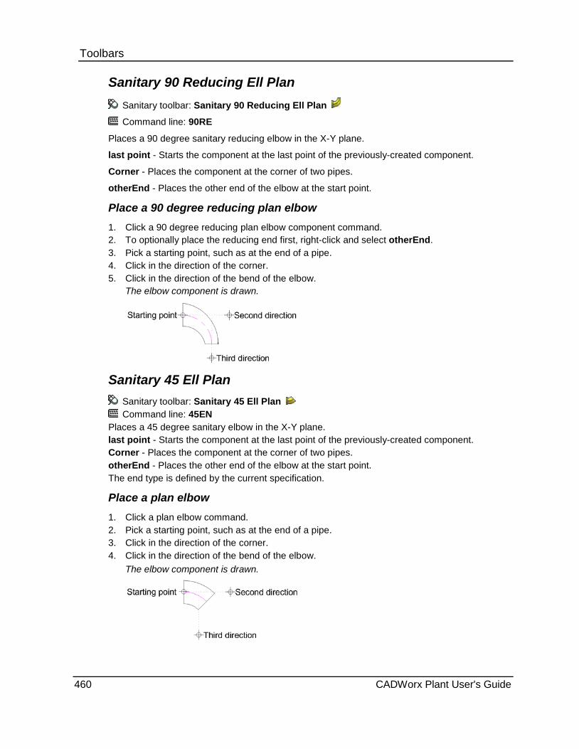
Toolbars Sanitary 90 Reducing Ell Plan
Sanitary toolbar: Sanitary 90 Reducing Ell Plan
Command line: 90RE
Places a 90 degree sanitary reducing elbow in the X-Y plane.
last point - Starts the component at the last point of the previously-created component.
Corner - Places the component at the corner of two pipes.
otherEnd - Places the other end of the elbow at the start point.
Place a 90 degree reducing plan elbow 1. Click a 90 degree reducing plan elbow component command. 2. To optionally place the reducing end first, right-click and select otherEnd. 3. Pick a starting point, such as at the end of a pipe. 4. Click in the direction of the corner. 5. Click in the direction of the bend of the elbow.
The elbow component is drawn.
Sanitary 45 Ell Plan Sanitary toolbar: Sanitary 45 Ell Plan Command line: 45EN
Places a 45 degree sanitary elbow in the X-Y plane. last point - Starts the component at the last point of the previously-created component. Corner - Places the component at the corner of two pipes. otherEnd - Places the other end of the elbow at the start point. The end type is defined by the current specification.
Place a plan elbow 1. Click a plan elbow command. 2. Pick a starting point, such as at the end of a pipe. 3. Click in the direction of the corner. 4. Click in the direction of the bend of the elbow.
The elbow component is drawn.
460 CADWorx Plant User's Guide

Toolbars Sanitary Tee Plan
Sanitary toolbar: Sanitary Tee Plan
Command line: TESE Places a straight sanitary tee in the X-Y plane. last point - Starts the component at the last point of the previously-created component. Middle - Places the tee at the centerline intersection of the branch and main of the tee. otherEnd - Places the other end of the tee at the start point. Branch - Places the branch of the tee at the start point. The end type is defined by the current specification. Place a plan tee 1. Click a plan tee command. 2. Click to select a starting point, such as at the end of a pipe. 3. Click in the direction of the main of the tee. 4. Click in the direction of the branch of the tee.
The tee component is drawn.
Reducing Tee Plan Sanitary toolbar: Sanitary Reducing Tee Plan Lined toolbar: Lined Reducing Tee Plan Command line: TERE
Places a reducing tee in the X-Y plane. last point - Starts the component at the last point of the previously-created component. Middle - Places the tee at the centerline intersection of the branch and main of the tee. otherEnd - Places the other end of the tee at the start point. Branch - Places the branch of the tee at the start point. The end type is defined by the current specification.
Place a plan tee 1. Click a plan tee command. 2. Click to select a starting point, such as at the end of a pipe. 3. Click in the direction of the main of the tee. 4. Click in the direction of the branch of the tee.
The tee component is drawn.
CADWorx Plant User's Guide 461

Toolbars Cross Plan
Sanitary toolbar: Sanitary Cross Plan
Lined toolbar: Lined Cross Plan
Command line: CRSE
Places a four-way straight cross in the X-Y plane.
last point - Starts the component at the last point of the previously-created component.
Center - Places the cross at the centerline intersection of the cross.
otherEnd - Places the other end of the cross at the start point.
Branch1 - Places the first branch of the cross at the start point.
Branch2 - Places the second branch of the cross at the start point.
The end type is defined by the current specification.
Place a plan cross 1. Click a four-way straight cross command.
2. Click to select a starting point, such as at the end of a pipe.
3. Click in the direction of the cross.
The cross component is drawn.
Cross Reducing Plan Sanitary toolbar: Sanitary Cross Reducing Plan
Lined toolbar: Lined Reducing Cross Plan
Command line: CRRE
Places a four-way reducing cross in the X-Y plane.
last point - Starts the component at the last point of the previously-created component.
Middle - Places the cross at the centerline intersection of the cross.
otherEnd - Places the other end of the cross at the start point.
Branch - Places the branch of the cross at the start point.
The end type is defined by the current specification.
462 CADWorx Plant User's Guide

Toolbars Place a sanitary plan reducing cross
1. Click Sanitary Cross Reducing Plan .
2. Click to select a starting point, such as at the end of a pipe.
3. Click in the direction of the cross.
4. Click in the direction of the branch end.
The cross component is drawn.
Lateral Plan Sanitary toolbar: Sanitary Lateral Plan
Lined toolbar: Lined Lateral Plan
Command line: LATE
Places a 45 degree lateral in the X-Y plane. last point - Starts the component at the last point of the previously-created component. Middle - Places the lateral at the centerline intersection of the branch and main. otherEnd - Places the other end of the lateral at the start point. Branch - Places the branch end of the lateral at the start point. The end type is defined by the current specification.
Place a plan lateral 1. Click a plan lateral command.
2. Click to select a starting point, such as at the end of a pipe.
3. Click in the direction of the main of the lateral.
4. Click in the direction of the branch of the lateral.
The lateral component is drawn.
Sanitary Lateral Reducing Plan Sanitary toolbar: Sanitary Lateral Reducing Plan
Command line: LARE
Places a 45 degree sanitary reducing lateral in the X-Y plane.
last point - Starts the component at the last point of the previously-created component.
Middle - Places the lateral at the centerline intersection of the branch and main.
otherEnd - Places the other end of the lateral at the start point. The end type is defined by the current specification.
Branch - Places the branch end of the lateral at the start point.
CADWorx Plant User's Guide 463
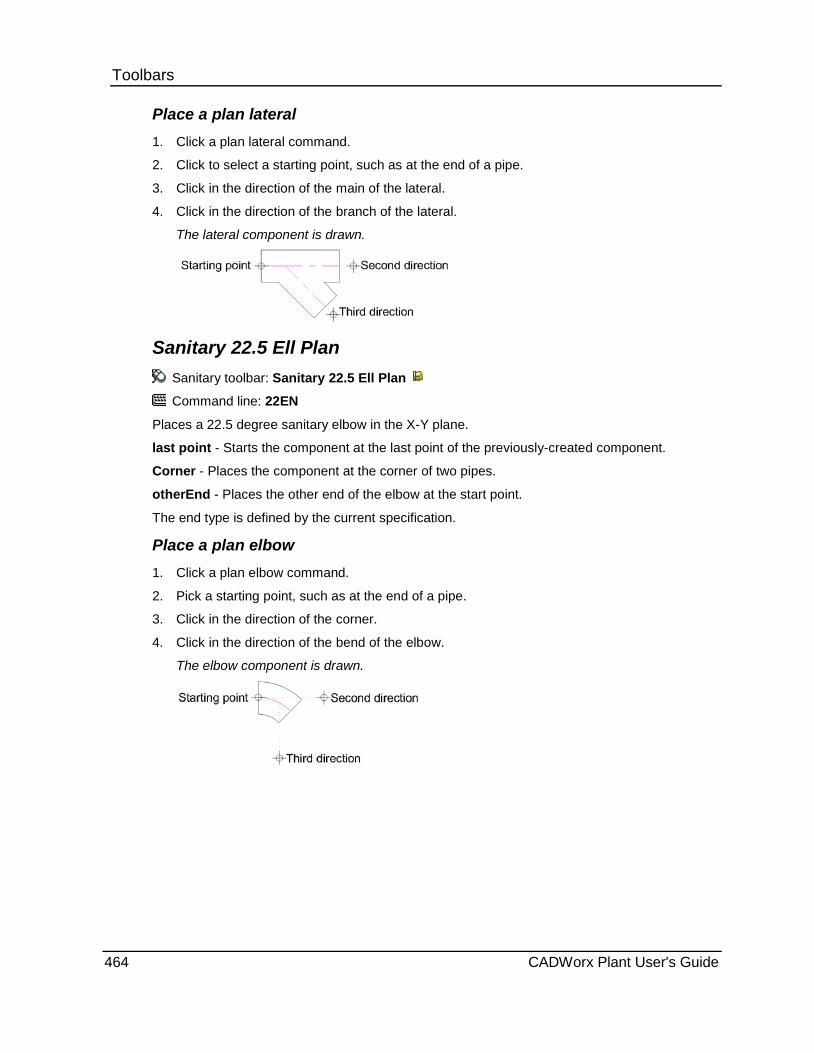
Toolbars Place a plan lateral 1. Click a plan lateral command.
2. Click to select a starting point, such as at the end of a pipe.
3. Click in the direction of the main of the lateral.
4. Click in the direction of the branch of the lateral.
The lateral component is drawn.
Sanitary 22.5 Ell Plan Sanitary toolbar: Sanitary 22.5 Ell Plan
Command line: 22EN
Places a 22.5 degree sanitary elbow in the X-Y plane.
last point - Starts the component at the last point of the previously-created component.
Corner - Places the component at the corner of two pipes.
otherEnd - Places the other end of the elbow at the start point.
The end type is defined by the current specification.
Place a plan elbow 1. Click a plan elbow command.
2. Pick a starting point, such as at the end of a pipe.
3. Click in the direction of the corner.
4. Click in the direction of the bend of the elbow.
The elbow component is drawn.
464 CADWorx Plant User's Guide
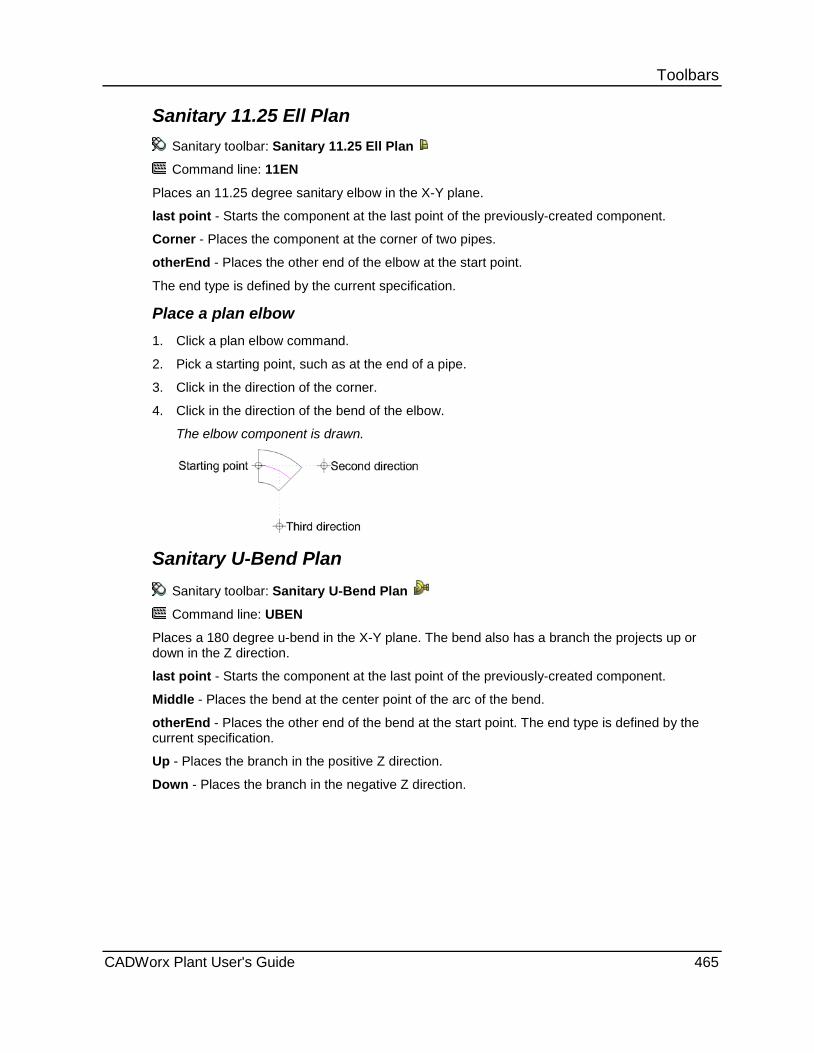
Toolbars Sanitary 11.25 Ell Plan
Sanitary toolbar: Sanitary 11.25 Ell Plan
Command line: 11EN
Places an 11.25 degree sanitary elbow in the X-Y plane.
last point - Starts the component at the last point of the previously-created component.
Corner - Places the component at the corner of two pipes.
otherEnd - Places the other end of the elbow at the start point.
The end type is defined by the current specification.
Place a plan elbow 1. Click a plan elbow command.
2. Pick a starting point, such as at the end of a pipe.
3. Click in the direction of the corner.
4. Click in the direction of the bend of the elbow.
The elbow component is drawn.
Sanitary U-Bend Plan Sanitary toolbar: Sanitary U-Bend Plan
Command line: UBEN
Places a 180 degree u-bend in the X-Y plane. The bend also has a branch the projects up or down in the Z direction.
last point - Starts the component at the last point of the previously-created component.
Middle - Places the bend at the center point of the arc of the bend.
otherEnd - Places the other end of the bend at the start point. The end type is defined by the current specification.
Up - Places the branch in the positive Z direction.
Down - Places the branch in the negative Z direction.
CADWorx Plant User's Guide 465
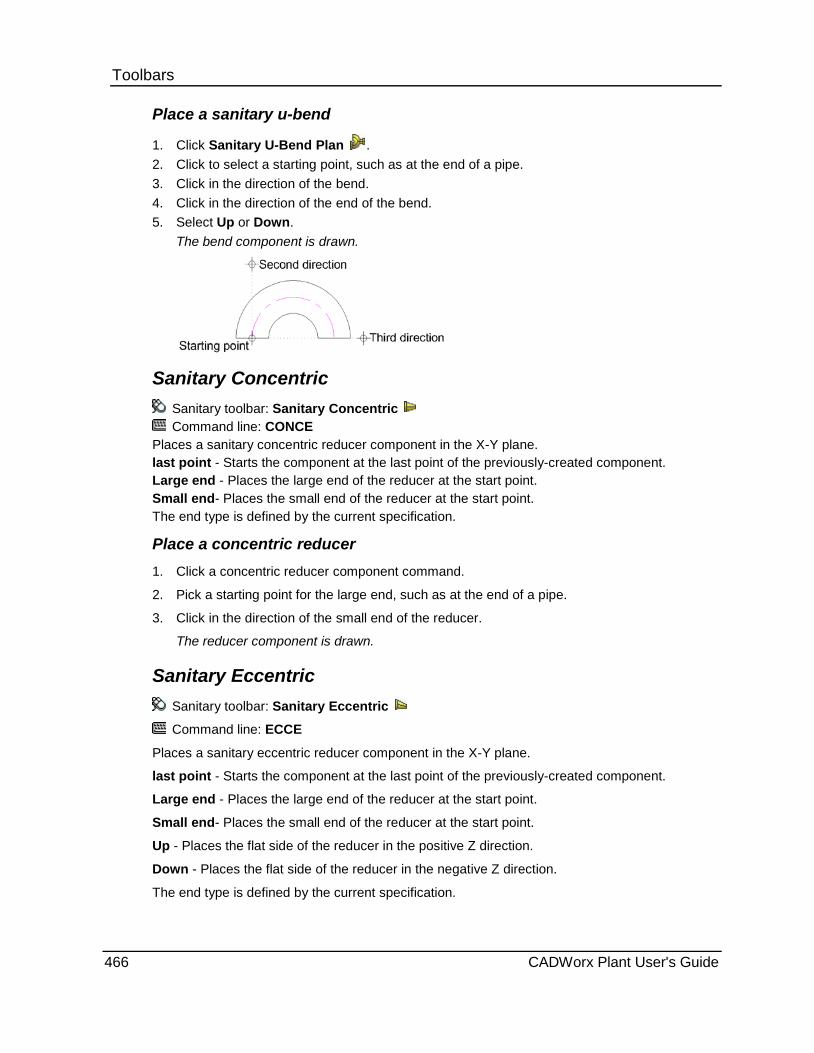
Toolbars Place a sanitary u-bend
1. Click Sanitary U-Bend Plan . 2. Click to select a starting point, such as at the end of a pipe. 3. Click in the direction of the bend. 4. Click in the direction of the end of the bend. 5. Select Up or Down.
The bend component is drawn.
Sanitary Concentric Sanitary toolbar: Sanitary Concentric Command line: CONCE
Places a sanitary concentric reducer component in the X-Y plane. last point - Starts the component at the last point of the previously-created component. Large end - Places the large end of the reducer at the start point. Small end- Places the small end of the reducer at the start point. The end type is defined by the current specification.
Place a concentric reducer 1. Click a concentric reducer component command.
2. Pick a starting point for the large end, such as at the end of a pipe.
3. Click in the direction of the small end of the reducer.
The reducer component is drawn.
Sanitary Eccentric Sanitary toolbar: Sanitary Eccentric
Command line: ECCE
Places a sanitary eccentric reducer component in the X-Y plane.
last point - Starts the component at the last point of the previously-created component.
Large end - Places the large end of the reducer at the start point.
Small end- Places the small end of the reducer at the start point.
Up - Places the flat side of the reducer in the positive Z direction.
Down - Places the flat side of the reducer in the negative Z direction.
The end type is defined by the current specification.
466 CADWorx Plant User's Guide
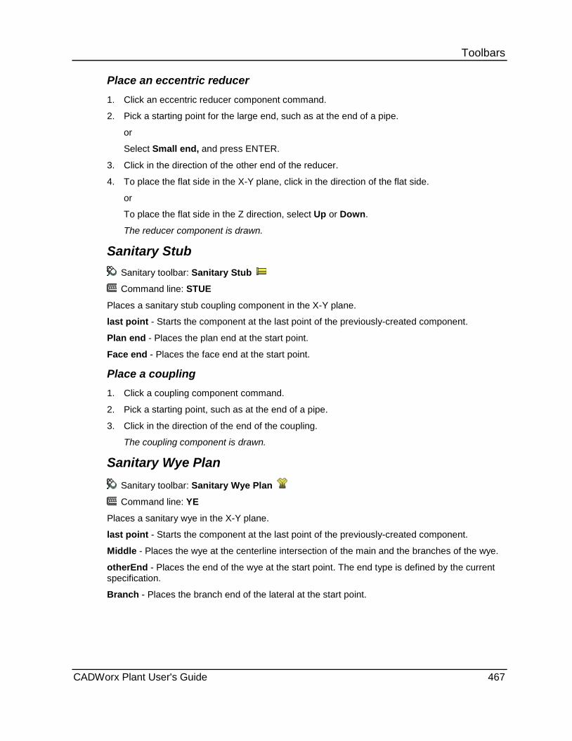
Toolbars Place an eccentric reducer 1. Click an eccentric reducer component command.
2. Pick a starting point for the large end, such as at the end of a pipe.
or
Select Small end, and press ENTER.
3. Click in the direction of the other end of the reducer.
4. To place the flat side in the X-Y plane, click in the direction of the flat side.
or
To place the flat side in the Z direction, select Up or Down.
The reducer component is drawn.
Sanitary Stub Sanitary toolbar: Sanitary Stub
Command line: STUE
Places a sanitary stub coupling component in the X-Y plane.
last point - Starts the component at the last point of the previously-created component.
Plan end - Places the plan end at the start point.
Face end - Places the face end at the start point.
Place a coupling 1. Click a coupling component command.
2. Pick a starting point, such as at the end of a pipe.
3. Click in the direction of the end of the coupling.
The coupling component is drawn.
Sanitary Wye Plan Sanitary toolbar: Sanitary Wye Plan
Command line: YE
Places a sanitary wye in the X-Y plane.
last point - Starts the component at the last point of the previously-created component.
Middle - Places the wye at the centerline intersection of the main and the branches of the wye.
otherEnd - Places the end of the wye at the start point. The end type is defined by the current specification.
Branch - Places the branch end of the lateral at the start point.
CADWorx Plant User's Guide 467
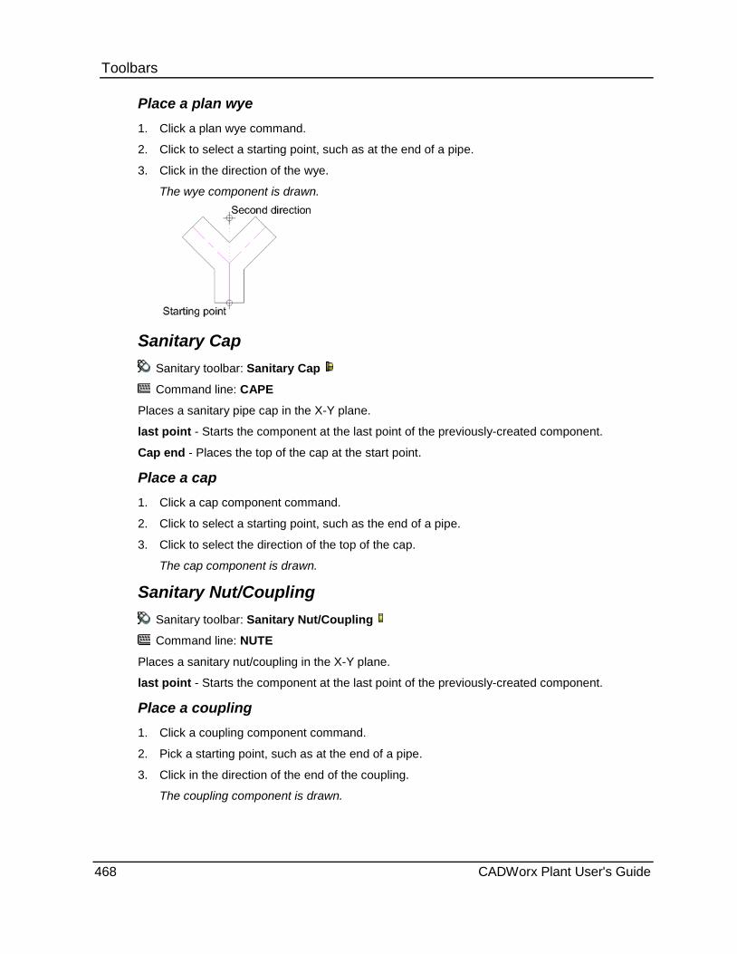
Toolbars Place a plan wye 1. Click a plan wye command.
2. Click to select a starting point, such as at the end of a pipe.
3. Click in the direction of the wye.
The wye component is drawn.
Sanitary Cap Sanitary toolbar: Sanitary Cap
Command line: CAPE
Places a sanitary pipe cap in the X-Y plane.
last point - Starts the component at the last point of the previously-created component.
Cap end - Places the top of the cap at the start point.
Place a cap 1. Click a cap component command.
2. Click to select a starting point, such as the end of a pipe.
3. Click to select the direction of the top of the cap.
The cap component is drawn.
Sanitary Nut/Coupling Sanitary toolbar: Sanitary Nut/Coupling
Command line: NUTE
Places a sanitary nut/coupling in the X-Y plane.
last point - Starts the component at the last point of the previously-created component.
Place a coupling 1. Click a coupling component command.
2. Pick a starting point, such as at the end of a pipe.
3. Click in the direction of the end of the coupling.
The coupling component is drawn.
468 CADWorx Plant User's Guide
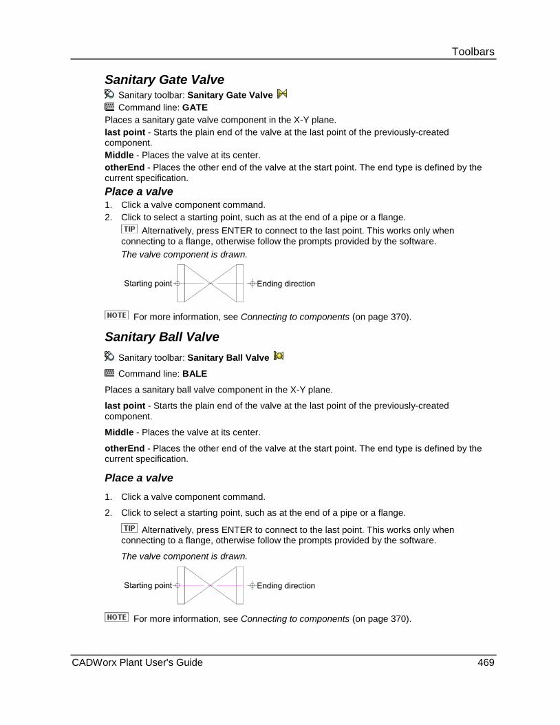
Toolbars Sanitary Gate Valve
Sanitary toolbar: Sanitary Gate Valve Command line: GATE
Places a sanitary gate valve component in the X-Y plane. last point - Starts the plain end of the valve at the last point of the previously-created component. Middle - Places the valve at its center. otherEnd - Places the other end of the valve at the start point. The end type is defined by the current specification. Place a valve 1. Click a valve component command. 2. Click to select a starting point, such as at the end of a pipe or a flange.
Alternatively, press ENTER to connect to the last point. This works only when connecting to a flange, otherwise follow the prompts provided by the software. The valve component is drawn.
For more information, see Connecting to components (on page 370).
Sanitary Ball Valve Sanitary toolbar: Sanitary Ball Valve
Command line: BALE
Places a sanitary ball valve component in the X-Y plane.
last point - Starts the plain end of the valve at the last point of the previously-created component.
Middle - Places the valve at its center.
otherEnd - Places the other end of the valve at the start point. The end type is defined by the current specification.
Place a valve 1. Click a valve component command.
2. Click to select a starting point, such as at the end of a pipe or a flange.
Alternatively, press ENTER to connect to the last point. This works only when connecting to a flange, otherwise follow the prompts provided by the software.
The valve component is drawn.
For more information, see Connecting to components (on page 370).
CADWorx Plant User's Guide 469

Toolbars Sanitary Globe Valve
Sanitary toolbar: Sanitary Globe Valve
Command line: GLBE
Places a sanitary globe valve component in the X-Y plane. last point - Starts the plain end of the valve at the last point of the previously-created component. Middle - Places the valve at its center. otherEnd - Places the other end of the valve at the start point. The end type is defined by the current specification.
Place a valve 1. Click a valve component command.
2. Click to select a starting point, such as at the end of a pipe or a flange.
Alternatively, press ENTER to connect to the last point. This works only when connecting to a flange, otherwise follow the prompts provided by the software.
The valve component is drawn.
For more information, see Connecting to components (on page 370).
Sanitary Plug Valve Sanitary toolbar: Sanitary Plug Valve Command line: PLUE
Places a sanitary plug valve component in the X-Y plane. last point - Starts the plain end of the valve at the last point of the previously-created component. Middle - Places the valve at its center. otherEnd - Places the other end of the valve at the start point. The end type is defined by the current specification.
Place a valve 1. Click a valve component command.
2. Click to select a starting point, such as at the end of a pipe or a flange.
Alternatively, press ENTER to connect to the last point. This works only when connecting to a flange, otherwise follow the prompts provided by the software.
The valve component is drawn.
For more information, see Connecting to components (on page 370).
470 CADWorx Plant User's Guide
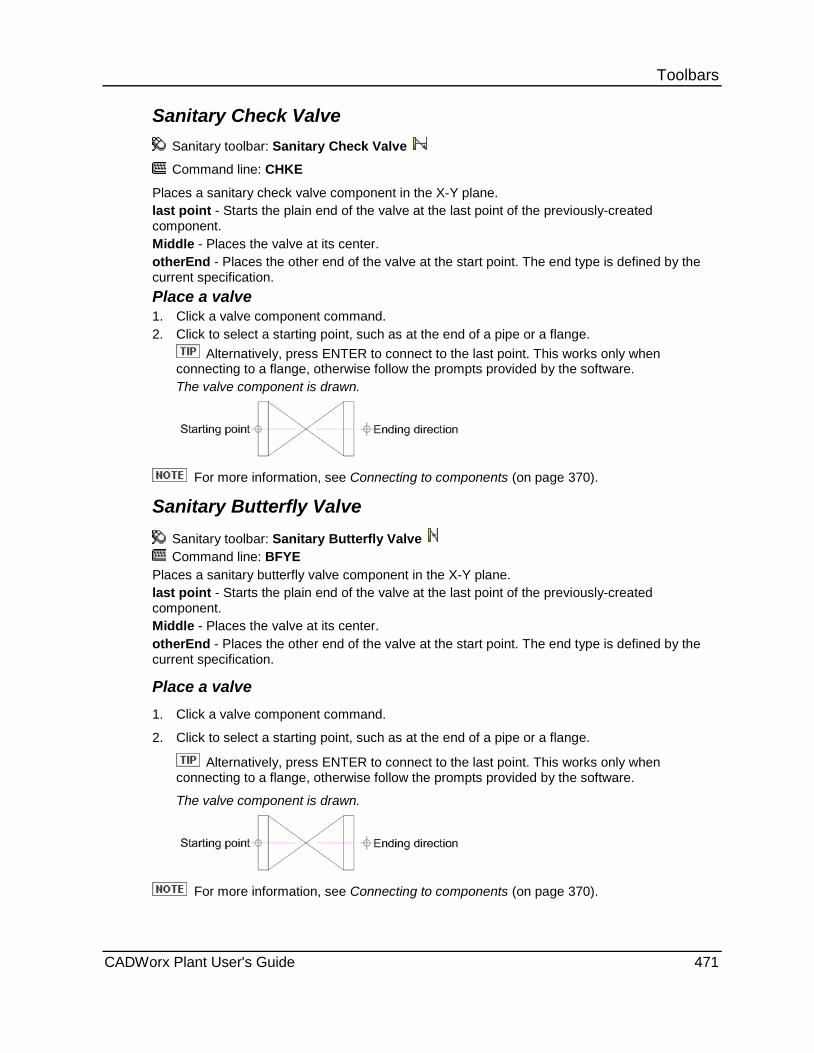
Toolbars Sanitary Check Valve
Sanitary toolbar: Sanitary Check Valve
Command line: CHKE
Places a sanitary check valve component in the X-Y plane. last point - Starts the plain end of the valve at the last point of the previously-created component. Middle - Places the valve at its center. otherEnd - Places the other end of the valve at the start point. The end type is defined by the current specification. Place a valve 1. Click a valve component command. 2. Click to select a starting point, such as at the end of a pipe or a flange.
Alternatively, press ENTER to connect to the last point. This works only when connecting to a flange, otherwise follow the prompts provided by the software. The valve component is drawn.
For more information, see Connecting to components (on page 370).
Sanitary Butterfly Valve Sanitary toolbar: Sanitary Butterfly Valve Command line: BFYE
Places a sanitary butterfly valve component in the X-Y plane. last point - Starts the plain end of the valve at the last point of the previously-created component. Middle - Places the valve at its center. otherEnd - Places the other end of the valve at the start point. The end type is defined by the current specification.
Place a valve 1. Click a valve component command.
2. Click to select a starting point, such as at the end of a pipe or a flange.
Alternatively, press ENTER to connect to the last point. This works only when connecting to a flange, otherwise follow the prompts provided by the software.
The valve component is drawn.
For more information, see Connecting to components (on page 370).
CADWorx Plant User's Guide 471
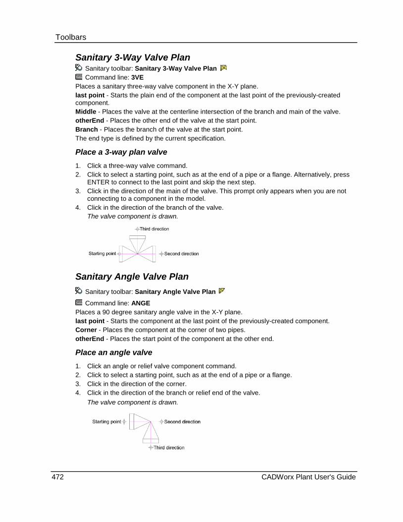
Toolbars Sanitary 3-Way Valve Plan
Sanitary toolbar: Sanitary 3-Way Valve Plan Command line: 3VE
Places a sanitary three-way valve component in the X-Y plane. last point - Starts the plain end of the component at the last point of the previously-created component. Middle - Places the valve at the centerline intersection of the branch and main of the valve. otherEnd - Places the other end of the valve at the start point. Branch - Places the branch of the valve at the start point. The end type is defined by the current specification.
Place a 3-way plan valve 1. Click a three-way valve command. 2. Click to select a starting point, such as at the end of a pipe or a flange. Alternatively, press
ENTER to connect to the last point and skip the next step. 3. Click in the direction of the main of the valve. This prompt only appears when you are not
connecting to a component in the model. 4. Click in the direction of the branch of the valve.
The valve component is drawn.
Sanitary Angle Valve Plan Sanitary toolbar: Sanitary Angle Valve Plan
Command line: ANGE Places a 90 degree sanitary angle valve in the X-Y plane. last point - Starts the component at the last point of the previously-created component. Corner - Places the component at the corner of two pipes. otherEnd - Places the start point of the component at the other end.
Place an angle valve 1. Click an angle or relief valve component command. 2. Click to select a starting point, such as at the end of a pipe or a flange. 3. Click in the direction of the corner. 4. Click in the direction of the branch or relief end of the valve.
The valve component is drawn.
472 CADWorx Plant User's Guide

Toolbars Sanitary Multi 1 Port Valve
Sanitary toolbar: Sanitary Multi 1 Port Valve
Command line: AIR1
Places a one-port pneumatic actuator air valve with the actuator in or normal to the X-Y plane.
last point - Starts the component at the last point of the previously-created component.
Up - Places the valve actuator in the positive Z direction.
Place a multi-port valve 1. Click a multi-port valve component command.
2. Click to select a starting point, such as at the end of a pipe.
3. To place the valve actuator in the X-Y plane, click in the direction of the actuator.
or
To place the valve actuator normal to the X-Y plane, select Up.
4. Type a value to rotate the valve about the actuator body axis.
The valve component is drawn.
Sanitary Multi 2 Port Valve Sanitary toolbar: Sanitary Multi 2 Port Valve
Command line: AIR2
Places a two-port pneumatic actuator air valve with the actuator in or normal to the X-Y plane.
last point - Starts the component at the last point of the previously-created component.
Up - Places the valve actuator in the positive Z direction.
Place a multi-port valve 1. Click a multi-port valve component command. 2. Click to select a starting point, such as at the end of a pipe. 3. To place the valve actuator in the X-Y plane, click in the direction of the actuator.
or To place the valve actuator normal to the X-Y plane, select Up.
4. Type a value to rotate the valve about the actuator body axis. The valve component is drawn.
Sanitary Multi 3 Port Valve Sanitary toolbar: Sanitary Multi 3 Port Valve
Command line: AIR3
Places a three-port pneumatic actuator air valve with the actuator in or normal to the X-Y plane.
last point - Starts the component at the last point of the previously-created component.
Up - Places the valve actuator in the positive Z direction.
CADWorx Plant User's Guide 473

Toolbars Place a multi-port valve 1. Click a multi-port valve component command.
2. Click to select a starting point, such as at the end of a pipe.
3. To place the valve actuator in the X-Y plane, click in the direction of the actuator.
or
To place the valve actuator normal to the X-Y plane, select Up.
4. Type a value to rotate the valve about the actuator body axis.
The valve component is drawn.
Modeling in 2D Commands are designed for plotting in 2D. The views in these commands appear this way only in a 2D drawing.
Sanitary 90 Ell Side Sanitary toolbar: Sanitary 90 Ell Side
Command line: H90EN
Places a 90 degree sanitary elbow normal to the X-Y plane.
last point - Starts the component at the last point of the previously-created component.
Corner - Places the component at the corner of two pipes.
Plan end - Places the plan end of the elbow at the start point.
Up - Places the elbow bend in the positive Z direction.
Down - Places the elbow bend in the negative Z direction.
Place a side or vertical elbow 1. Click a side or vertical elbow component command.
2. Click to select a starting point, such as at the end of a pipe.
3. Click in the direction of the corner.
4. Select Up or Down.
The elbow component is drawn.
474 CADWorx Plant User's Guide

Toolbars Sanitary 90 Reducing Ell Side
Sanitary toolbar: Sanitary 90 Reducing Ell Side
Command line: H90RE
Places a 90 degree sanitary reducing elbow normal to the X-Y plane.
last point - Starts the component at the last point of the previously-created component.
Corner - Places the component at the corner of two pipes.
ENgagement end - Places the reducing end of the elbow at the start point.
Up - Places the elbow bend in the positive Z direction.
Down - Places the elbow bend in the negative Z direction.
Place a side reducing elbow 1. Click a side reducing plan elbow component command. 2. To optionally place the reducing end first, right-click and select Small. 3. Pick a starting point, such as at the end of a pipe. 4. Click in the direction of the corner. 5. Select Up or Down.
The elbow component is drawn.
Sanitary 45 Ell Side Sanitary toolbar: Sanitary 45 Ell Side
Command line: H45EN Places a 45 degree sanitary elbow normal to the X-Y plane. last point - Starts the component at the last point of the previously-created component. Corner - Places the component at the corner of two pipes. FErrule end - Places the ferrule end of the elbow at the start point. Up - Places the elbow bend in the positive Z direction. Down - Places the elbow bend in the negative Z direction.
Place a side or vertical elbow 1. Click a side or vertical elbow component command. 2. Click to select a starting point, such as at the end of a pipe. 3. Click in the direction of the corner. 4. Select Up or Down.
The elbow component is drawn.
CADWorx Plant User's Guide 475
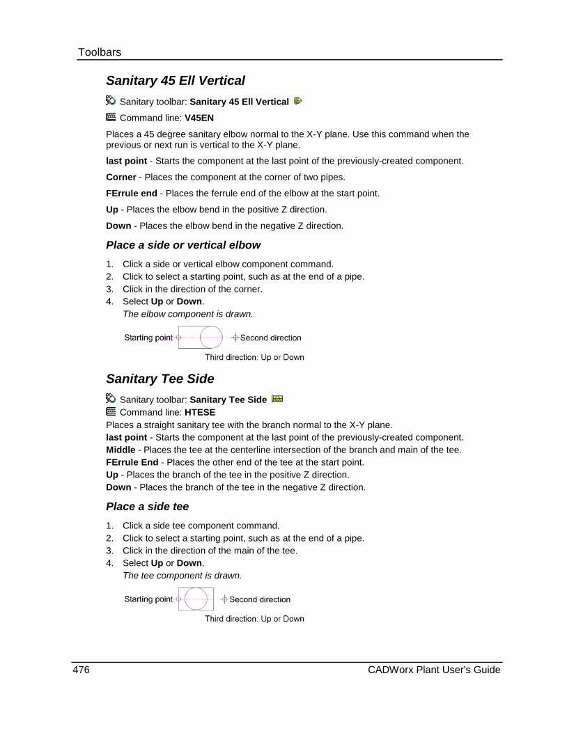
Toolbars Sanitary 45 Ell Vertical
Sanitary toolbar: Sanitary 45 Ell Vertical
Command line: V45EN
Places a 45 degree sanitary elbow normal to the X-Y plane. Use this command when the previous or next run is vertical to the X-Y plane.
last point - Starts the component at the last point of the previously-created component.
Corner - Places the component at the corner of two pipes.
FErrule end - Places the ferrule end of the elbow at the start point.
Up - Places the elbow bend in the positive Z direction.
Down - Places the elbow bend in the negative Z direction.
Place a side or vertical elbow 1. Click a side or vertical elbow component command. 2. Click to select a starting point, such as at the end of a pipe. 3. Click in the direction of the corner. 4. Select Up or Down.
The elbow component is drawn.
Sanitary Tee Side Sanitary toolbar: Sanitary Tee Side Command line: HTESE
Places a straight sanitary tee with the branch normal to the X-Y plane. last point - Starts the component at the last point of the previously-created component. Middle - Places the tee at the centerline intersection of the branch and main of the tee. FErrule End - Places the other end of the tee at the start point. Up - Places the branch of the tee in the positive Z direction. Down - Places the branch of the tee in the negative Z direction.
Place a side tee 1. Click a side tee component command. 2. Click to select a starting point, such as at the end of a pipe. 3. Click in the direction of the main of the tee. 4. Select Up or Down.
The tee component is drawn.
476 CADWorx Plant User's Guide
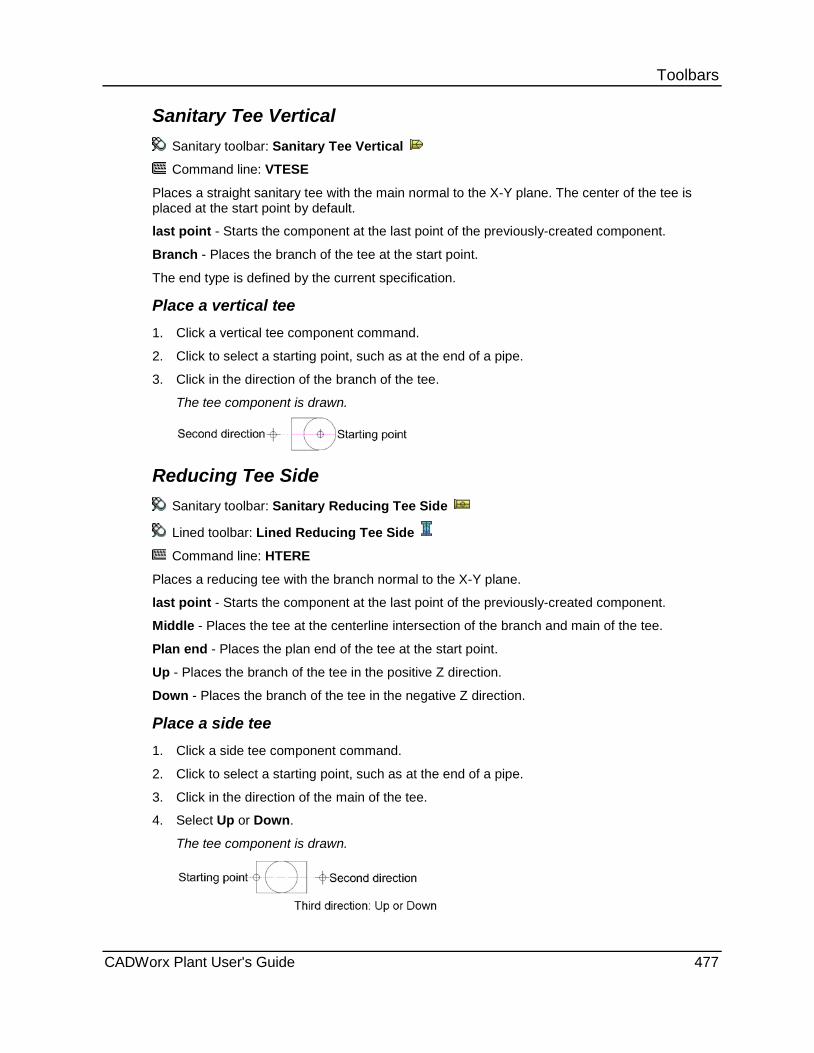
Toolbars Sanitary Tee Vertical
Sanitary toolbar: Sanitary Tee Vertical
Command line: VTESE
Places a straight sanitary tee with the main normal to the X-Y plane. The center of the tee is placed at the start point by default.
last point - Starts the component at the last point of the previously-created component.
Branch - Places the branch of the tee at the start point.
The end type is defined by the current specification.
Place a vertical tee 1. Click a vertical tee component command.
2. Click to select a starting point, such as at the end of a pipe.
3. Click in the direction of the branch of the tee.
The tee component is drawn.
Reducing Tee Side Sanitary toolbar: Sanitary Reducing Tee Side
Lined toolbar: Lined Reducing Tee Side
Command line: HTERE
Places a reducing tee with the branch normal to the X-Y plane.
last point - Starts the component at the last point of the previously-created component.
Middle - Places the tee at the centerline intersection of the branch and main of the tee.
Plan end - Places the plan end of the tee at the start point.
Up - Places the branch of the tee in the positive Z direction.
Down - Places the branch of the tee in the negative Z direction.
Place a side tee 1. Click a side tee component command.
2. Click to select a starting point, such as at the end of a pipe.
3. Click in the direction of the main of the tee.
4. Select Up or Down.
The tee component is drawn.
CADWorx Plant User's Guide 477
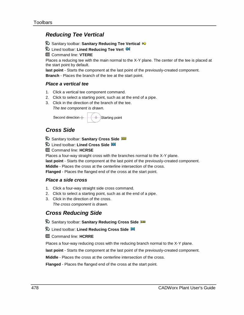
Toolbars Reducing Tee Vertical
Sanitary toolbar: Sanitary Reducing Tee Vertical Lined toolbar: Lined Reducing Tee Vert Command line: VTERE
Places a reducing tee with the main normal to the X-Y plane. The center of the tee is placed at the start point by default. last point - Starts the component at the last point of the previously-created component. Branch - Places the branch of the tee at the start point.
Place a vertical tee 1. Click a vertical tee component command. 2. Click to select a starting point, such as at the end of a pipe. 3. Click in the direction of the branch of the tee.
The tee component is drawn.
Cross Side Sanitary toolbar: Sanitary Cross Side Lined toolbar: Lined Cross Side Command line: HCRSE
Places a four-way straight cross with the branches normal to the X-Y plane. last point - Starts the component at the last point of the previously-created component. Middle - Places the cross at the centerline intersection of the cross. Flanged - Places the flanged end of the cross at the start point.
Place a side cross 1. Click a four-way straight side cross command. 2. Click to select a starting point, such as at the end of a pipe. 3. Click in the direction of the cross.
The cross component is drawn.
Cross Reducing Side Sanitary toolbar: Sanitary Reducing Cross Side
Lined toolbar: Lined Reducing Cross Side
Command line: HCRRE
Places a four-way reducing cross with the reducing branch normal to the X-Y plane.
last point - Starts the component at the last point of the previously-created component.
Middle - Places the cross at the centerline intersection of the cross.
Flanged - Places the flanged end of the cross at the start point.
478 CADWorx Plant User's Guide
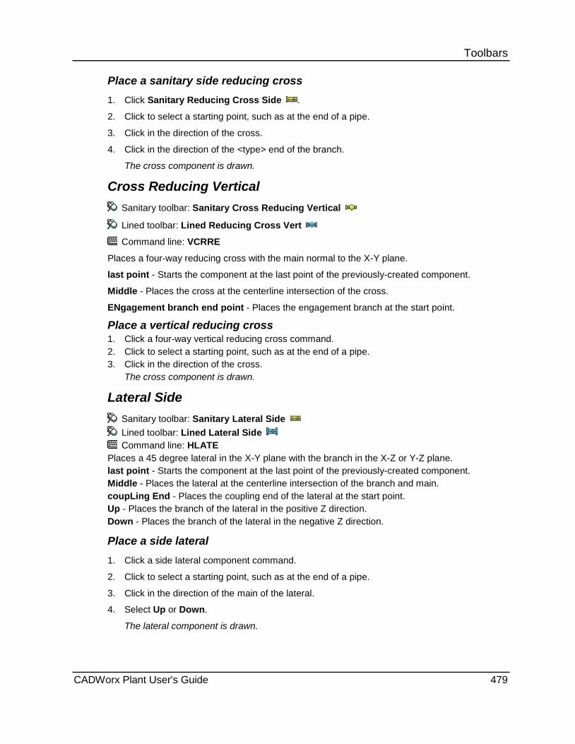
Toolbars Place a sanitary side reducing cross 1. Click Sanitary Reducing Cross Side .
2. Click to select a starting point, such as at the end of a pipe.
3. Click in the direction of the cross.
4. Click in the direction of the <type> end of the branch.
The cross component is drawn.
Cross Reducing Vertical Sanitary toolbar: Sanitary Cross Reducing Vertical
Lined toolbar: Lined Reducing Cross Vert
Command line: VCRRE
Places a four-way reducing cross with the main normal to the X-Y plane.
last point - Starts the component at the last point of the previously-created component.
Middle - Places the cross at the centerline intersection of the cross.
ENgagement branch end point - Places the engagement branch at the start point.
Place a vertical reducing cross 1. Click a four-way vertical reducing cross command. 2. Click to select a starting point, such as at the end of a pipe. 3. Click in the direction of the cross.
The cross component is drawn.
Lateral Side Sanitary toolbar: Sanitary Lateral Side Lined toolbar: Lined Lateral Side Command line: HLATE
Places a 45 degree lateral in the X-Y plane with the branch in the X-Z or Y-Z plane. last point - Starts the component at the last point of the previously-created component. Middle - Places the lateral at the centerline intersection of the branch and main. coupLing End - Places the coupling end of the lateral at the start point. Up - Places the branch of the lateral in the positive Z direction. Down - Places the branch of the lateral in the negative Z direction.
Place a side lateral 1. Click a side lateral component command.
2. Click to select a starting point, such as at the end of a pipe.
3. Click in the direction of the main of the lateral.
4. Select Up or Down.
The lateral component is drawn.
CADWorx Plant User's Guide 479
Toolbars Lateral Vertical
Sanitary toolbar: Sanitary Lateral Vertical
Lined toolbar: Lined Lateral Vert
Command line: VLATE
Places a 45 degree lateral with the main normal to the X-Y plane. The center of the lateral is placed at the start point by default.
last point - Starts the component at the last point of the previously-created component.
Up - Places the branch of the lateral in the positive Z direction.
Down - Places the branch of the lateral in the negative Z direction.
Place a vertical lateral 1. Click a vertical lateral component command.
2. Click to select a starting point, such as at the end of a pipe.
3. Click in the direction of the branch of the lateral.
4. Select Up or Down.
The lateral component is drawn.
Sanitary Lateral Reducing Side Sanitary toolbar: Sanitary Lateral Reducing Side
Command line: HLARE
Places a 45 degree sanitary reducing lateral in the X-Y plane with the branch in the X-Z or Y-Z plane.
last point - Starts the component at the last point of the previously-created component.
Middle - Places the lateral at the centerline intersection of the branch and main.
coupLing end - Places the other end of the lateral at the start point.
Up - Places the branch of the lateral in the positive Z direction.
Down - Places the branch of the lateral in the negative Z direction.
Place a side lateral 1. Click a side lateral component command.
2. Click to select a starting point, such as at the end of a pipe.
3. Click in the direction of the main of the lateral.
4. Select Up or Down.
The lateral component is drawn.
480 CADWorx Plant User's Guide
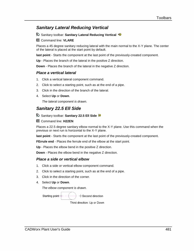
Toolbars Sanitary Lateral Reducing Vertical
Sanitary toolbar: Sanitary Lateral Reducing Vertical
Command line: VLARE
Places a 45 degree sanitary reducing lateral with the main normal to the X-Y plane. The center of the lateral is placed at the start point by default.
last point - Starts the component at the last point of the previously-created component.
Up - Places the branch of the lateral in the positive Z direction.
Down - Places the branch of the lateral in the negative Z direction.
Place a vertical lateral 1. Click a vertical lateral component command.
2. Click to select a starting point, such as at the end of a pipe.
3. Click in the direction of the branch of the lateral.
4. Select Up or Down.
The lateral component is drawn.
Sanitary 22.5 Ell Side Sanitary toolbar: Sanitary 22.5 Ell Side
Command line: H22EN
Places a 22.5 degree sanitary elbow normal to the X-Y plane. Use this command when the previous or next run is horizontal to the X-Y plane.
last point - Starts the component at the last point of the previously-created component.
FErrule end - Places the ferrule end of the elbow at the start point.
Up - Places the elbow bend in the positive Z direction.
Down - Places the elbow bend in the negative Z direction.
Place a side or vertical elbow 1. Click a side or vertical elbow component command.
2. Click to select a starting point, such as at the end of a pipe.
3. Click in the direction of the corner.
4. Select Up or Down.
The elbow component is drawn.
CADWorx Plant User's Guide 481
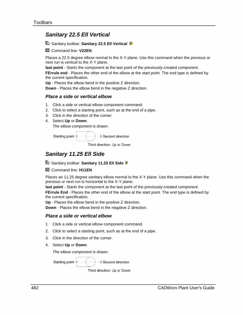
Toolbars Sanitary 22.5 Ell Vertical
Sanitary toolbar: Sanitary 22.5 Ell Vertical
Command line: V22EN
Places a 22.5 degree elbow normal to the X-Y plane. Use this command when the previous or next run is vertical to the X-Y plane. last point - Starts the component at the last point of the previously-created component. FErrule end - Places the other end of the elbow at the start point. The end type is defined by the current specification. Up - Places the elbow bend in the positive Z direction. Down - Places the elbow bend in the negative Z direction.
Place a side or vertical elbow 1. Click a side or vertical elbow component command. 2. Click to select a starting point, such as at the end of a pipe. 3. Click in the direction of the corner. 4. Select Up or Down.
The elbow component is drawn.
Sanitary 11.25 Ell Side Sanitary toolbar: Sanitary 11.25 Ell Side
Command line: H11EN
Places an 11.25 degree sanitary elbow normal to the X-Y plane. Use this command when the previous or next run is horizontal to the X-Y plane. last point - Starts the component at the last point of the previously-created component. FErrule End - Places the other end of the elbow at the start point. The end type is defined by the current specification. Up - Places the elbow bend in the positive Z direction. Down - Places the elbow bend in the negative Z direction.
Place a side or vertical elbow 1. Click a side or vertical elbow component command.
2. Click to select a starting point, such as at the end of a pipe.
3. Click in the direction of the corner.
4. Select Up or Down.
The elbow component is drawn.
482 CADWorx Plant User's Guide

Toolbars Sanitary 11.25 Ell Vertical
Sanitary toolbar: Sanitary 11.25 Ell Vertical
Command line: V11EN
Places an 11.25 degree elbow normal to the X-Y plane. Use this command when the previous or next run is vertical to the X-Y plane.
last point - Starts the component at the last point of the previously-created component.
FErrule end - Places the other end of the elbow at the start point. The end type is defined by the current specification.
Up - Places the elbow bend in the positive Z direction.
Down - Places the elbow bend in the negative Z direction.
Place a side or vertical elbow 1. Click a side or vertical elbow component command.
2. Click to select a starting point, such as at the end of a pipe.
3. Click in the direction of the corner.
4. Select Up or Down.
The elbow component is drawn.
Sanitary U-Bend Side Sanitary toolbar: Sanitary U-Bend Side
Command line: HUBEN
Places a 180 degree u-bend normal to the X-Y plane with the return ends on the X-Y plane. This command is typically used with pipe that is normal to the X-Y plane. last point - Starts the component at the last point of the previously-created component. Center - Places the bend at the center point of the arc of the bend. <Type> End - Places the other end of the bend at the start point. The end type is defined by the current specification. Up - Places the branch in the positive Z direction. Down - Places the branch in the negative Z direction.
Place a sanitary side or vertical u-bend
1. Click Sanitary U-Bend Side or Sanitary U-Bend Vertical . 2. Click to select a starting point, such as at the end of a pipe. 3. Click in the direction of the end of the bend. 4. Select Up or Down. 5. Click in the direction of the branch.
The bend component is drawn.
CADWorx Plant User's Guide 483

Toolbars Sanitary U-Bend Vertical
Sanitary toolbar: Sanitary U-Bend Vertical
Command line: VUBEN
Places a 180 degree u-bend normal to the X-Y plane with the return ends also normal to the X-Y plane. This command is typically used with pipe that is on the X-Y plane.
last point - Starts the component at the last point of the previously-created component.
Center - Places the bend at the center point of the arc of the bend.
<Type> End - Places the other end of the bend at the start point. The end type is defined by the current specification.
Up - Places the branch in the positive Z direction.
Down - Places the branch in the negative Z direction.
Place a sanitary side or vertical u-bend
1. Click Sanitary U-Bend Side or Sanitary U-Bend Vertical .
2. Click to select a starting point, such as at the end of a pipe.
3. Click in the direction of the end of the bend.
4. Select Up or Down.
5. Click in the direction of the branch.
The bend component is drawn.
Sanitary Wye Side Sanitary toolbar: Sanitary Wye Side
Command line: HYE
Places a sanitary wye on the X-Y plane with the branches normal to the X-Y plane. This command is typically used with pipe that is on the X-Y plane.
last point - Starts the component at the last point of the previously-created component.
Middle - Places the wye at the centerline intersection of the main and branches of the wye.
Place a side wye 1. Click a side wye command.
2. Click to select a starting point, such as at the end of a pipe.
3. Click in the direction of the wye main.
The wye component is drawn.
484 CADWorx Plant User's Guide

Toolbars Sanitary Wye Vertical
Sanitary toolbar: Sanitary Wye Vertical
Command line: VYE
Places a sanitary wye normal to the X-Y plane with the branches also normal to the X-Y plane. This command is typically used with pipe that is normal to the X-Y plane.
last point - Starts the component at the last point of the previously-created component.
Middle - Places the wye at the centerline intersection of the main and branches of the wye.
Place a vertical wye 1. Click a vertical wye command.
2. Click to select a starting point, such as at the end of a pipe.
3. Click in the direction of the wye branches.
The wye component is drawn.
Sanitary 3-Way Valve Side Sanitary toolbar: Sanitary 3-Way Valve Side
Command line: H3VE
Places a three-way valve component with the branch normal to the X-Y plane.
last point - Starts the plain end of the component at the last point of the previously-created component.
Middle - Places the valve at the centerline intersection of the branch and main of the valve.
ENgagement end - Places the engagement end of the valve at the start point.
Up - Places the branch of the valve in the positive Z direction.
Down - Places the branch of the valve in the negative Z direction.
Place a 3-way side valve 1. Click a three-way side valve component command.
2. Click to select a starting point, such as at the end of a pipe or a flange.
3. Click in the direction of the main of the valve.
4. Select Up or Down.
The valve component is drawn.
Sanitary 3-Way Valve Vertical Sanitary toolbar: Sanitary 3-Way Valve Vertical
Command line: V3VE
Places a sanitary three-way valve component with the main normal to the X-Y plane. The center of the valve is placed at the start point by default.
last point - Starts the component at the last point of the previously-created component.
FErrule branch end point - Places the ferrule end of the valve at the start point.
CADWorx Plant User's Guide 485
Toolbars Place a 3-way vertical valve 1. Click a three-way vertical valve component command.
2. Click to select a starting point, such as at the end of a pipe or a flange.
3. Click in the direction of the branch of the valve.
The valve component is drawn.
Sanitary Angle Valve Side Sanitary toolbar: Sanitary Angle Valve Side
Command line: HANGE
Places a 90 degree sanitary angle valve component with the branch normal to the X-Y plane.
last point - Starts the component at the last point of the previously-created component.
Corner - Places the component at the corner of two pipes.
ENgagement end - Places the engagement end of the valve at the start point.
Up - Places the branch of the valve in the positive Z direction.
Down - Places the branch of the valve in the negative Z direction.
Place an angle side valve 1. Click an angle or relief side valve component command.
2. Click to select a starting point, such as at the end of a pipe.
3. Click in the direction of the main of the valve.
4. Select Up or Down.
The valve component is drawn.
Victaulic Plant menu: Toolbars > Victaulic
The commands on the Victaulic toolbar can be used for modeling in 3D or 2D mode depending on how you define the drawing mode. For more information, see 3D Modeling versus 2D Modeling (on page 370).
Command Name Command Line
Pipe - Places a victaulic pipe component. For more information, see Pipe (on page 375).
PIPW
Plan 90 LR Ell - Places a 90 degree long radius elbow in the X-Y plane. For more information, see Plan 90 LR Ell (on page 375).
90LR
486 CADWorx Plant User's Guide

Toolbars
Command Name Command Line
Plan 90 SR Ell - Places a 90 degree short radius elbow in the X-Y plane. For more information, see Plan 90 SR Ell (on page 376).
90SR
Plan 45 Ell - Places a 45 degree elbow in the X-Y plane. For more information, see Plan 45 Ell (on page 377).
45LR
Plan 90 Reducing Ell - Places a 90 degree reducing elbow in the X-Y plane. For more information, see Plan 90 Reducing Ell (on page 377).
90RD
Side 90 Reducing Ell - Places a 90 degree reducing elbow normal to the X-Y plane. For more information, see Side 90 Reducing Ell (on page 392).
H90RD
Plan 11.25 Ell - Places an 11.25 degree elbow in the X-Y plane. For more information, see Plan 11.25 Ell (on page 388).
11LR
Plan 22.5 Ell - Places a 22.5 degree elbow in the X-Y plane. For more information, see Plan 22.5 Ell (on page 389).
22LR
Plan Tee - Places a straight tee in the X-Y plane. For more information, see Plan Tee (on page 378).
TESW
Plan Reducing Tee - Places a straight reducing tee in the X-Y plane. For more information, see Plan Reducing Tee (on page 378).
TERW
Plan Cross - Places a four-way straight cross in the X-Y plane. For more information, see Plan Cross (on page 381).
CRSW
Plan Reducing Cross - Places a four-way reducing cross in the X-Y plane. For more information, see Plan Reducing Cross (on page 382).
CCRW
Plan Wye - Places a wye in the X-Y plane. For more information, see Plan Wye (on page 389).
YB
Plan Lateral - Places a 45 degree lateral in the X-Y plane. For more information, see Plan Lateral (on page 382).
LATW
Plan Strainer - Places a strainer in the X-Y plane. For more information, see Flanged Tee Plan (on page 444).
TEFL
CADWorx Plant User's Guide 487

Toolbars
Command Name Command Line
Conc Reducer - Places a concentric reducer component in the X-Y plane. For more information, see Conc Reducer (on page 380)
CONC
Ecc Reducer - Places an eccentric reducer component in the X-Y plane. For more information, see Ecc Reducer (on page 380).
ECC
Victaulic Cap - Places a pipe cap in the X-Y plane. For more information, see Cap (on page 381).
CAPW
Victaulic Coupling - Places a coupling in the X-Y plane. For more information, see Coupling (on page 441).
CPS
Victaulic Flange - Places a flange in the X-Y plane. For more information, see Slip-On Flange (on page 404).
FLGO
Victaulic Butterfly Valve - Places a butterfly valve component in the X-Y plane. For more information, see Butterfly Valve (on page 420).
BFYF
Victaulic Check Valve - Places a check valve component in the X-Y plane. For more information, see Check Valve (on page 419).
CHKF
Victaulic Ball Valve - Places a ball valve component in the X-Y plane. For more information, see Ball Valve (on page 417).
BALF
Victaulic Plug Valve - Places a plug valve component in the X-Y plane. For more information, see Plug Valve (on page 419).
PLUF
The commands in the table below are designed for modeling in 2D.
Command Name Command Line
Side 90 LR Ell - Places a 90 degree long radius elbow normal to the X-Y plane. For more information, see Side 90 LR Ell (on page 390).
H90LR
Side 90 SR Ell - Places a 90 degree short radius elbow normal to the X-Y plane. For more information, see Side 90 SR Ell (on page 391)
H90SR
488 CADWorx Plant User's Guide

Toolbars
Command Name Command Line
Side 45 Ell - Places a 45 degree elbow normal to the X-Y plane. For more information, see Plan 45 Ell (on page 377).
H45LR
Vert 45 Ell - Places a 45 degree elbow normal to the X-Y plane. For more information, see Vert 45 Ell (on page 392).
V45LR
Side 11.25 Ell - Places an 11.25 degree elbow normal to the X-Y plane. For more information, see Side 11.25 Ell (on page 399).
H11LR
Vert 11.25 Ell - Places an 11.25 degree elbow normal to the X-Y plane. For more information, see Vert 11.25 Ell (on page 399).
V11LR
Side 22.5 Ell - Places a 22.5 degree elbow normal to the X-Y plane. For more information, see Side 22.5 Ell (on page 400).
H22LR
Vert 22.5 Ell - Places a 22.5 degree elbow normal to the X-Y plane. For more information, see Vert 22.5 Ell (on page 400).
V22LR
Side Tee - Places a straight tee with the branch normal to the X-Y plane. For more information, see Side Tee (on page 393).
HTESW
Vert Tee - Places a straight tee with the main normal to the X-Y plane. For more information, see Vert Tee (on page 393).
VTESW
Side Reducing Tee - Places a straight reducing tee with the branch normal to the X-Y plane. For more information, see Side Reducing Tee (on page 394).
HTERW
Vert Reducing Tee - Places a straight reducing tee with the main normal to the X-Y plane. For more information, see Vert Reducing Tee (on page 394).
VTERW
Side Cross - Places a four-way straight cross with the branch normal to the X-Y plane. For more information, see Side Cross (on page 397).
HCRSW
Side Reducing Cross - Places a four-way reducing cross with the reducing branch normal to the X-Y plane. For more information, see Side Reducing Cross (on page 397).
HCCRW
CADWorx Plant User's Guide 489
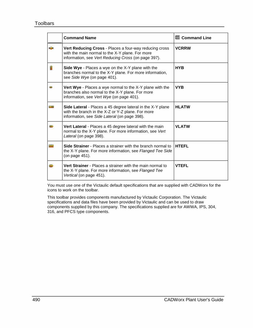
Toolbars
Command Name Command Line
Vert Reducing Cross - Places a four-way reducing cross with the main normal to the X-Y plane. For more information, see Vert Reducing Cross (on page 397).
VCRRW
Side Wye - Places a wye on the X-Y plane with the branches normal to the X-Y plane. For more information, see Side Wye (on page 401).
HYB
Vert Wye - Places a wye normal to the X-Y plane with the branches also normal to the X-Y plane. For more information, see Vert Wye (on page 401).
VYB
Side Lateral - Places a 45 degree lateral in the X-Y plane with the branch in the X-Z or Y-Z plane. For more information, see Side Lateral (on page 398).
HLATW
Vert Lateral - Places a 45 degree lateral with the main normal to the X-Y plane. For more information, see Vert Lateral (on page 398).
VLATW
Side Strainer - Places a strainer with the branch normal to the X-Y plane. For more information, see Flanged Tee Side (on page 451).
HTEFL
Vert Strainer - Places a strainer with the main normal to the X-Y plane. For more information, see Flanged Tee Vertical (on page 451).
VTEFL
You must use one of the Victaulic default specifications that are supplied with CADWorx for the icons to work on the toolbar.
This toolbar provides components manufactured by Victaulic Corporation. The Victaulic specifications and data files have been provided by Victaulic and can be used to draw components supplied by this company. The specifications supplied are for AWWA, IPS, 304, 316, and PFCS type components.
490 CADWorx Plant User's Guide

Toolbars
Threaded/Socket Plant menu: Toolbars > Thrd/SW Fittings
The Command Line column in the table below shows the command for the socket weld component and the equivalent threaded component. Use the Threaded and Socket Weld commands on the Setup Size/Spec Panel (on page 27) to switch between these two modes.
The commands on the Thrd/SW Fittings toolbar can be used for modeling in 3D or 2D mode depending on how you define the drawing mode. For more information, see 3D Modeling versus 2D Modeling (on page 370).
Command Name Command Line
Thrd/SW Pipe - Places a threaded/socket pipe component. For more information, see Thrd/SW Pipe (on page 496).
PIPF
Nipple - Places a pipe nipple in the X-Y plane. For more information, see Nipple (on page 497).
NIP
Tube - Attaches tubing to any 2D or 3D polyline. For more information, see Tube (on page 498).
TUBE
Thrd/SW 90 Ell Plan - Places a 90 degree threaded/socket elbow in the X-Y plane. For more information, see Thrd/SW 90 Ell Plan (on page 499).
90S/90T
Thrd/SW 90 Street Ell Plan - Places a 90 degree threaded/socket street elbow in the X-Y plane. For more information, see Thrd/SW 90 Street Ell Plan (on page 499).
90SS/90ST
Thrd/SW 45 Ell Plan - Places a 45 degree threaded/socket elbow in the X-Y plane. For more information, see Thrd/SW 45 Ell Plan (on page 500).
45S/45T
Thrd/SW 90 Red Ell Plan - Places a 90 degree threaded/socket reducing elbow in the X-Y plane. For more information, see Thrd/SW 90 Red Ell Plan (on page 501).
90RS/90RT
Thrd/SW Tee Plan - Places a threaded/socket straight tee in the X-Y plane. For more information, see Thrd/SW Tee Plan (on page 501).
TESS/TEST
Thrd/SW Tee Red Plan - Places a straight threaded/socket reducing tee in the X-Y plane. For more information, see Thrd/SW Tee Red Plan (on page 502).
TERS/TERT
Thrd/SW Conc Swage - Places a concentric reducer swage in the X-Y plane. For more information, see Thrd/SW Conc Swage (on page 502).
SWGC
CADWorx Plant User's Guide 491
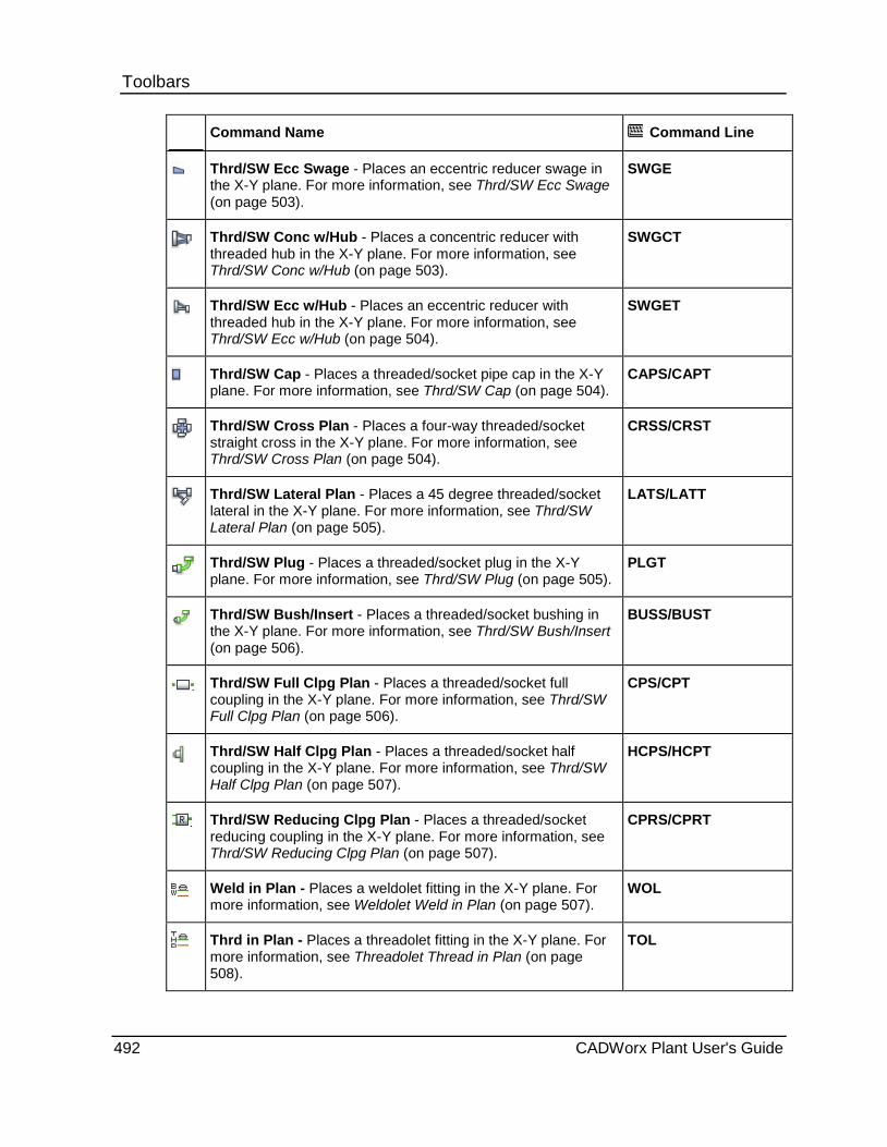
Toolbars
Command Name Command Line
Thrd/SW Ecc Swage - Places an eccentric reducer swage in the X-Y plane. For more information, see Thrd/SW Ecc Swage (on page 503).
SWGE
Thrd/SW Conc w/Hub - Places a concentric reducer with threaded hub in the X-Y plane. For more information, see Thrd/SW Conc w/Hub (on page 503).
SWGCT
Thrd/SW Ecc w/Hub - Places an eccentric reducer with threaded hub in the X-Y plane. For more information, see Thrd/SW Ecc w/Hub (on page 504).
SWGET
Thrd/SW Cap - Places a threaded/socket pipe cap in the X-Y plane. For more information, see Thrd/SW Cap (on page 504).
CAPS/CAPT
Thrd/SW Cross Plan - Places a four-way threaded/socket straight cross in the X-Y plane. For more information, see Thrd/SW Cross Plan (on page 504).
CRSS/CRST
Thrd/SW Lateral Plan - Places a 45 degree threaded/socket lateral in the X-Y plane. For more information, see Thrd/SW Lateral Plan (on page 505).
LATS/LATT
Thrd/SW Plug - Places a threaded/socket plug in the X-Y plane. For more information, see Thrd/SW Plug (on page 505).
PLGT
Thrd/SW Bush/Insert - Places a threaded/socket bushing in the X-Y plane. For more information, see Thrd/SW Bush/Insert (on page 506).
BUSS/BUST
Thrd/SW Full Clpg Plan - Places a threaded/socket full coupling in the X-Y plane. For more information, see Thrd/SW Full Clpg Plan (on page 506).
CPS/CPT
Thrd/SW Half Clpg Plan - Places a threaded/socket half coupling in the X-Y plane. For more information, see Thrd/SW Half Clpg Plan (on page 507).
HCPS/HCPT
Thrd/SW Reducing Clpg Plan - Places a threaded/socket reducing coupling in the X-Y plane. For more information, see Thrd/SW Reducing Clpg Plan (on page 507).
CPRS/CPRT
Weld in Plan - Places a weldolet fitting in the X-Y plane. For more information, see Weldolet Weld in Plan (on page 507).
WOL
Thrd in Plan - Places a threadolet fitting in the X-Y plane. For more information, see Threadolet Thread in Plan (on page 508).
TOL
492 CADWorx Plant User's Guide

Toolbars
Command Name Command Line
SW in Plan - Places a sockolet fitting in the X-Y plane. For more information, see Sockolet Socket Weld in Plan (on page 508).
SOL
EOL-Weld in Plan - Places an elbowlet fitting in the X-Y plane on a plan elbow. For more information, see Elbowlet Weld in Plan (on page 508).
EOLW
EOL-Thrd in Plan - Places an elbowlet fitting in the X-Y plane on a plan elbow. For more information, see Elbowlet Thread in Plan (on page 509).
EOLT
EOL-SW in Plan - Places an elbowlet fitting in the X-Y plane on a plan elbow. For more information, see Elbowlet Socket Weld in Plan (on page 509).
EOLS
LOL-Weld in Plan - Places a lateral 45 degree fitting in the X-Y plane. For more information, see Latrolet Weld in Plan (on page 509).
LOLW
LOL-Thrd in Plan - Places a lateral 45 degree fitting in the X-Y plane. For more information, see Latrolet Thread in Plan (on page 510).
LOLT
LOL- SW in Plan - Places a lateral 45 degree fitting in the X-Y plane. For more information, see Latrolet Socket Weld in Plan (on page 510).
LOLS
Weld in Plan - Places a nipolet fitting in the X-Y plane. The branch end of the fitting is plain. For more information, see Nipolet Weld in Plan (on page 510).
NOLP
Thrd in Plan - Places a nipolet fitting in the X-Y plane. The branch end of the fitting is threaded. For more information, see Nipolet Thread in Plan (on page 511).
NOLT
Thrd/SW Union - Places a threaded/socket union in the X-Y plane. For more information, see Thrd/SW Union (on page 511).
UNS/UNT
The commands in the table below are designed for modeling in 2D.
Command Name Command Line
Thrd/SW 90 Ell Side - Places a 90 degree threaded/socket elbow normal to the X-Y plane. For more information, see Thrd/SW 90 Ell Side (on page 511).
H90S/H90T
CADWorx Plant User's Guide 493
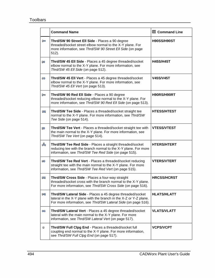
Toolbars
Command Name Command Line
Thrd/SW 90 Street Ell Side - Places a 90 degree threaded/socket street elbow normal to the X-Y plane. For more information, see Thrd/SW 90 Street Ell Side (on page 512).
H90SS/H90ST
Thrd/SW 45 Ell Side - Places a 45 degree threaded/socket elbow normal to the X-Y plane. For more information, see Thrd/SW 45 Ell Side (on page 512).
H45S/H45T
Thrd/SW 45 Ell Vert - Places a 45 degree threaded/socket elbow normal to the X-Y plane. For more information, see Thrd/SW 45 Ell Vert (on page 513).
V45S/V45T
Thrd/SW 90 Red Ell Side - Places a 90 degree threaded/socket reducing elbow normal to the X-Y plane. For more information, see Thrd/SW 90 Red Ell Side (on page 513).
H90RS/H90RT
Thrd/SW Tee Side - Places a threaded/socket straight tee normal to the X-Y plane. For more information, see Thrd/SW Tee Side (on page 514).
HTESS/HTEST
Thrd/SW Tee Vert - Places a threaded/socket straight tee with the main normal to the X-Y plane. For more information, see Thrd/SW Tee Vert (on page 514).
VTESS/VTEST
Thrd/SW Tee Red Side - Places a straight threaded/socket reducing tee with the branch normal to the X-Y plane. For more information, see Thrd/SW Tee Red Side (on page 515).
HTERS/HTERT
Thrd/SW Tee Red Vert - Places a threaded/socket reducing straight tee with the main normal to the X-Y plane. For more information, see Thrd/SW Tee Red Vert (on page 515).
VTERS/VTERT
Thrd/SW Cross Side - Places a four-way straight threaded/socket cross with the branch normal to the X-Y plane. For more information, see Thrd/SW Cross Side (on page 516).
HRCSS/HCRST
Thrd/SW Lateral Side - Places a 45 degree threaded/socket lateral in the X-Y plane with the branch in the X-Z or Y-Z plane. For more information, see Thrd/SW Lateral Side (on page 516).
HLATS/HLATT
Thrd/SW Lateral Vert - Places a 45 degree threaded/socket lateral with the main normal to the X-Y plane. For more information, see Thrd/SW Lateral Vert (on page 517).
VLATS/VLATT
Thrd/SW Full Clpg End - Places a threaded/socket full coupling end normal to the X-Y plane. For more information, see Thrd/SW Full Clpg End (on page 517).
VCPS/VCPT
494 CADWorx Plant User's Guide

Toolbars
Command Name Command Line
Thrd/SW Half Clpg End - Places a threaded/socket half coupling component end normal to the X-Y plane. For more information, see Thrd/SW Half Clpg End (on page 517).
VHCPS/VHCPT
Thrd/SW Reducing Clpg End - Places a threaded/socket reducing coupling end normal to the X-Y plane. For more information, see Thrd/SW Reducing Clpg End (on page 518).
VCPRS/VCPRT
Weld in Vertical - Places a weldolet fitting normal to the X-Y plane. For more information, see Weldolet Weld in Vertical (on page 518).
VWOL
Thrd in Vertical - Places a threadolet fitting normal to the X-Y plane. For more information, see Threadolet Thread in Vertical (on page 519).
VTOL
SW in Vertical - Places a sockolet fitting normal to the X-Y plane. For more information, see Sockolet Socket Weld in Vertical (on page 519).
VSO:
EOL-Weld in Side - Places an elbowlet fitting with in the X-Y plane on a side elbow. For more information, see Elbowlet Weld in Side (on page 519).
HEOLW
EOL-Weld in Vert - Places an elbowlet fitting normal to the X-Y plane on a side elbow. For more information, see Elbowlet Weld in Vertical (on page 520).
VEOLW
EOL-Thrd in Side - Places an elbowlet fitting with in the X-Y plane on a side elbow. For more information, see Elbowlet Thread in Side (on page 520).
HEOLT
EOL-Thrd in Vert - Places an elbowlet fitting normal to the X-Y plane on a side elbow. For more information, see Elbowlet Thread in Vertical (on page 521).
VEOLT
EOL-SW in Side - Places an elbowlet fitting with in the X-Y plane on a side elbow. For more information, see Elbowlet Socket Weld in Side (on page 521).
HEOLS
EOL-SW in Vert - Places an elbowlet fitting normal to the X-Y plane on a side elbow. For more information, see Elbowlet Socket Weld in Vertical (on page 521).
VEOLS
LOL-Weld in Side - Places a lateral fitting 45 degrees out of the X-Y plane. For more information, see Latrolet Weld in Side (on page 522).
HLOLW
CADWorx Plant User's Guide 495
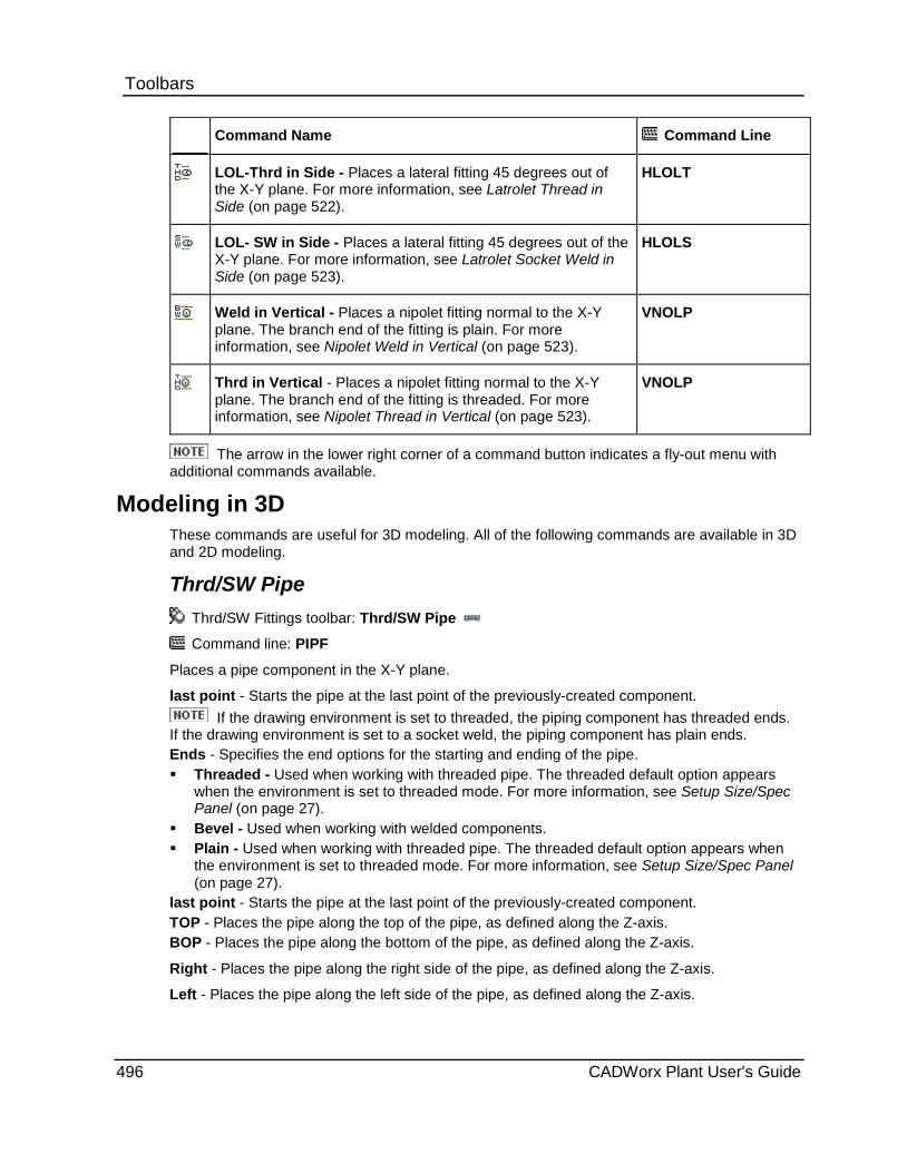
Toolbars
Command Name Command Line
LOL-Thrd in Side - Places a lateral fitting 45 degrees out of the X-Y plane. For more information, see Latrolet Thread in Side (on page 522).
HLOLT
LOL- SW in Side - Places a lateral fitting 45 degrees out of the X-Y plane. For more information, see Latrolet Socket Weld in Side (on page 523).
HLOLS
Weld in Vertical - Places a nipolet fitting normal to the X-Y plane. The branch end of the fitting is plain. For more information, see Nipolet Weld in Vertical (on page 523).
VNOLP
Thrd in Vertical - Places a nipolet fitting normal to the X-Y plane. The branch end of the fitting is threaded. For more information, see Nipolet Thread in Vertical (on page 523).
VNOLP
The arrow in the lower right corner of a command button indicates a fly-out menu with additional commands available.
Modeling in 3D These commands are useful for 3D modeling. All of the following commands are available in 3D and 2D modeling.
Thrd/SW Pipe Thrd/SW Fittings toolbar: Thrd/SW Pipe
Command line: PIPF
Places a pipe component in the X-Y plane.
last point - Starts the pipe at the last point of the previously-created component. If the drawing environment is set to threaded, the piping component has threaded ends.
If the drawing environment is set to a socket weld, the piping component has plain ends. Ends - Specifies the end options for the starting and ending of the pipe. Threaded - Used when working with threaded pipe. The threaded default option appears
when the environment is set to threaded mode. For more information, see Setup Size/Spec Panel (on page 27).
Bevel - Used when working with welded components. Plain - Used when working with threaded pipe. The threaded default option appears when
the environment is set to threaded mode. For more information, see Setup Size/Spec Panel (on page 27).
last point - Starts the pipe at the last point of the previously-created component. TOP - Places the pipe along the top of the pipe, as defined along the Z-axis. BOP - Places the pipe along the bottom of the pipe, as defined along the Z-axis.
Right - Places the pipe along the right side of the pipe, as defined along the Z-axis.
Left - Places the pipe along the left side of the pipe, as defined along the Z-axis.
496 CADWorx Plant User's Guide

Toolbars Place a threaded/socket pipe 1. Click a pipe component command.
2. Click to select a starting point, or type coordinates in the command line and press ENTER.
3. Click to select an ending point, or type coordinates in the command line and press ENTER.
4. If you receive a prompt for end types, type the option on the command line and press ENTER.
The pipe component is drawn.
Nipple Thrd/SW Fittings toolbar: Nipple
Command line: NIP
Places a pipe nipple in the X-Y plane.
last point - Starts the pipe at the last point of the previously-created component.
Length - Defines the length of the fitting component.
Close - Reads the close distance as specified in the data file.
Ends - Specifies the end options for the starting and ending of the pipe.
Threaded - Used when working with threaded pipe. The threaded default option appears when the environment is set to threaded mode. For more information, see Setup Size/Spec Panel (on page 27).
Bevel - Used when working with welded components.
Plain - Used when working with threaded pipe. The threaded default option appears when the environment is set to threaded mode. For more information, see Setup Size/Spec Panel (on page 27).
Place a nipple 1. Click Nipple . Alternatively, type NIP on the command line and then press ENTER.
2. Click to select a starting point.
3. Click to select an ending point.
4. Specify the end option for the start of the component.
5. Specify the end option for the end of the component.
The end options default depends on which options you have set.
The pipe nipple is drawn.
CADWorx Plant User's Guide 497

Toolbars Tube
Thrd/SW Fittings toolbar: Tube
Command line: TUBE
Attaches tubing to any 2D or 3D polyline. Different radii can be placed at each vertex of the polyline, or you can define a common radius for all corners.
Use the Router command on the RT Panel (on page 221) for useful 3D polyline routing capabilities.
Tubing uses the pipe component entry within the CADWorx Plant specifications. Pipe and tubing can be used concurrently. Tubing can occupy a range of 1/8” – 1/2”, whereas regular pipe can occupy 3/4” and above. Tubing can be set up as an optional component, or the specification can be set up to only handle tubing.
After tubing is placed in the drawing, other components can be inserted into it. Like normal piping, tubing also automatically breaks. Even after a component is inserted, the tubing remains as one piece. When edited with CEDIT, the tubing attached to a single polyline also acts as one piece.
Grouping is controlled by the PICKSTYLE environmental variable, which must be turned on for the tubing to act as one piece. Alternatively, you can use the CADWorx GROUPTOG command to turn the AutoCAD grouping control on or off. For more information, see Group On/Off (on page 175).
Enter corner radius - Defines the radius to be used at each vertex.
Manual - Places individual radii at each corner of the selected polyline. The software pauses at each vertex so that the radius can be defined. A rubber-banded line back to the actual vertex is shown in the drawing.
Tubing is exported to a live database, and appears in the CADWorx Bill of Material as one piece.
Tubing is exported to the CADWorx ISOGEN isometric generator and appears in the ISOGEN material list.
Tubing is not exported to CAESAR II.
Tubing can be stretched only at the end point of the tube run by using the square grip point. You can also use the plus grip points to route pipe from the tubing.
Place tubing
1. Click Tube . Alternatively, type TUBE on the command line and then press ENTER.
2. Type the required radius.
3. Select the 2D or 3D polyline.
The tubing is attached.
498 CADWorx Plant User's Guide
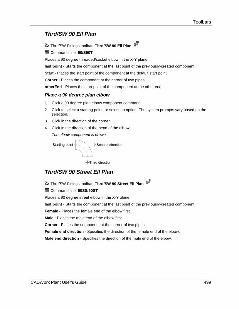
Toolbars Thrd/SW 90 Ell Plan
Thrd/SW Fittings toolbar: Thrd/SW 90 Ell Plan
Command line: 90/S90T
Places a 90 degree threaded/socket elbow in the X-Y plane.
last point - Starts the component at the last point of the previously-created component.
Start - Places the start point of the component at the default start point.
Corner - Places the component at the corner of two pipes.
otherEnd - Places the start point of the component at the other end.
Place a 90 degree plan elbow 1. Click a 90 degree plan elbow component command.
2. Click to select a starting point, or select an option. The system prompts vary based on the selection.
3. Click in the direction of the corner.
4. Click in the direction of the bend of the elbow.
The elbow component is drawn.
Thrd/SW 90 Street Ell Plan
Thrd/SW Fittings toolbar: Thrd/SW 90 Street Ell Plan
Command line: 90SS/90ST
Places a 90 degree street elbow in the X-Y plane.
last point - Starts the component at the last point of the previously-created component.
Female - Places the female end of the elbow first.
Male - Places the male end of the elbow first.
Corner - Places the component at the corner of two pipes.
Female end direction - Specifies the direction of the female end of the elbow.
Male end direction - Specifies the direction of the male end of the elbow.
CADWorx Plant User's Guide 499

Toolbars Place a 90 degree street plan elbow
1. Click Thrd/SW 90 Street Ell Plan . Alternatively, type 90SS on the command line and then press ENTER.
If the drawing environment is set to threaded mode, type 90ST on the command line.
2. To optionally place the male end first, right-click and select Male.
3. Pick a starting point, such as the end of a pipe.
4. Click in the direction of the corner.
5. Click in the direction of the male end of the elbow.
If the male end is placed first, the system prompts you for placement of the female end.
The elbow component is drawn.
Thrd/SW 45 Ell Plan
Thrd/SW Fittings toolbar: Thrd/SW 45 Ell Plan Command line: 45S/45T
Places a 45 degree threaded/socket elbow in the X-Y plane. last point - Starts the component at the last point of the previously-created component. Start - Places the start point of the component at the default start point. Corner - Places the component at the corner of two pipes. otherEnd - Places the start point of the component at the other end.
Place a plan elbow 1. Click a plan elbow command.
2. Pick a starting point, such as at the end of a pipe.
3. Click in the direction of the corner.
4. Click in the direction of the bend of the elbow.
The elbow component is drawn.
500 CADWorx Plant User's Guide
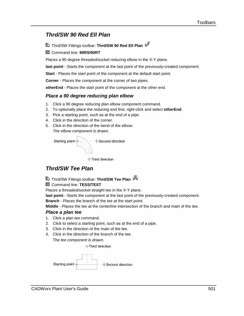
Toolbars Thrd/SW 90 Red Ell Plan
Thrd/SW Fittings toolbar: Thrd/SW 90 Red Ell Plan
Command line: 90RS/90RT
Places a 90 degree threaded/socket reducing elbow in the X-Y plane.
last point - Starts the component at the last point of the previously-created component.
Start - Places the start point of the component at the default start point.
Corner - Places the component at the corner of two pipes.
otherEnd - Places the start point of the component at the other end.
Place a 90 degree reducing plan elbow 1. Click a 90 degree reducing plan elbow component command. 2. To optionally place the reducing end first, right-click and select otherEnd. 3. Pick a starting point, such as at the end of a pipe. 4. Click in the direction of the corner. 5. Click in the direction of the bend of the elbow.
The elbow component is drawn.
Thrd/SW Tee Plan
Thrd/SW Fittings toolbar: Thrd/SW Tee Plan Command line: TESS/TEST
Places a threaded/socket straight tee in the X-Y plane. last point - Starts the component at the last point of the previously-created component. Branch - Places the branch of the tee at the start point. Middle - Places the tee at the centerline intersection of the branch and main of the tee. Place a plan tee 1. Click a plan tee command. 2. Click to select a starting point, such as at the end of a pipe. 3. Click in the direction of the main of the tee. 4. Click in the direction of the branch of the tee.
The tee component is drawn.
CADWorx Plant User's Guide 501

Toolbars Thrd/SW Tee Red Plan
Thrd/SW Fittings toolbar: Thrd/SW Tee Red Plan
Command line: TESS/TERT
Places a threaded/socket straight reducing tee in the X-Y plane. last point - Starts the component at the last point of the previously-created component. Branch - Places the branch of the tee at the start point. Middle - Places the tee at the centerline intersection of the branch and main of the tee.
Place a plan tee 1. Click a plan tee command. 2. Click to select a starting point, such as at the end of a pipe. 3. Click in the direction of the main of the tee. 4. Click in the direction of the branch of the tee.
The tee component is drawn.
Thrd/SW Conc Swage Thrd/SW Fittings toolbar: Thrd/SW Conc Swage
Command line: SWGC
Places a concentric reducer swage in the X-Y plane.
last point - Starts the component at the last point of the previously-created component. Large end - Places the non-reducing end at the start point Small end - Places the reducing end at the start point. Large end type - Specifies the end type connection at the large end of the swage. Small end type - Specifies the end type connection at the small end of the swage.
This command reverses the main and reduction sizes automatically after execution.
Place a concentric reducer swage
1. Click Thrd/SW Conc Swage . Alternatively, type SWGC on the command line and then press ENTER.
2. Pick a starting point for the large end, such as at the end of a pipe.
3. Click in the direction of the small end of the reducer.
4. Specify the end type connection at the large end of the reducer.
Type the required alpha description.
5. Specify the end type connection at the small end of the reducer.
The reducer component is drawn.
502 CADWorx Plant User's Guide

Toolbars Thrd/SW Ecc Swage
Thrd/SW Fittings toolbar: Thrd/SW Ecc Swage
Command line: SWGE
Places an eccentric reducer swage in the X-Y plane.
last point - Starts the component at the last point of the previously-created component.
Large end - Places the non-reducing end at the start point.
Small end - Places the reducing end at the start point.
Large end type - Specifies the end type connection at the large end of the swage.
Small end type - Specifies the end type connection at the small end of the swage.
Up - Places the flat side of the reducer in the positive Z direction.
Down - Places the flat side of the reducer in the negative Z direction.
This command reverses the main and reduction sizes automatically after execution.
Place an eccentric reducer swage
1. Click Thrd/SW Ecc Swage . Alternatively, type SWGE on the command line and then press ENTER.
2. Pick a starting point for the large end, such as at the end of a pipe. 3. Click in the direction of the small end of reducer. 4. To place the flat side in the X-Y plane, click in the direction of the flat side.
or To place the flat side in the Z direction, select Up or Down.
5. Specify the end type connection at the large end of the reducer. Type the required alpha description.
6. Specify the end type connection at the small end of the reducer. The reducer component is drawn.
Thrd/SW Conc w/Hub Thrd/SW Fittings toolbar: Thrd/SW Conc w/Hub
Command line: SWGCT
Places a concentric reducer with threaded hub in the X-Y plane.
last point - Starts the component at the last point of the previously-created component.
Small end - Places the reducing end at the start point.
Place a concentric reducer 1. Click a concentric reducer component command.
2. Pick a starting point for the large end, such as at the end of a pipe.
3. Click in the direction of the small end of the reducer.
The reducer component is drawn.
CADWorx Plant User's Guide 503
Toolbars Thrd/SW Ecc w/Hub
Thrd/SW Fittings toolbar: Thrd/SW Ecc w/Hub
Command line: SWGET
Places an eccentric reducer with threaded hub in the X-Y plane.
last point - Starts the component at the last point of the previously-created component.
Small end - Places the reducing end at the start point.
Up - Places the flat side of the reducer in the positive Z direction.
Down - Places the flat side of the reducer in the negative Z direction.
Place an eccentric reducer 1. Click an eccentric reducer component command. 2. Pick a starting point for the large end, such as at the end of a pipe.
or Select Small end, and press ENTER.
3. Click in the direction of the other end of the reducer. 4. To place the flat side in the X-Y plane, click in the direction of the flat side.
or To place the flat side in the Z direction, select Up or Down. The reducer component is drawn.
Thrd/SW Cap Thrd/SW Fittings toolbar: Thrd/SW Cap Command line: CAPS/CAPT
Places a threaded/socket pipe cap in the X-Y plane. last point - Starts the component at the last point of the previously-created component. Cap end - Places the top of the cap at the start point. Place a cap 1. Click a cap component command.
2. Click to select a starting point, such as the end of a pipe.
3. Click to select the direction of the top of the cap.
The cap component is drawn.
Thrd/SW Cross Plan
Thrd/SW Fittings toolbar: Thrd/SW Cross Plan
Command line: CRSS/CRST
Places a four-way threaded/socket straight cross in the X-Y plane.
last point - Starts the component at the last point of the previously-created component.
Middle - Places the cross at the centerline intersection of the cross.
Branch - Places the branch of the cross at the start point.
504 CADWorx Plant User's Guide

Toolbars Place a plan cross 1. Click a four-way straight cross command. 2. Click to select a starting point, such as at the end of a pipe. 3. Click in the direction of the cross.
The cross component is drawn.
Thrd/SW Lateral Plan
Thrd/SW Fittings toolbar: Thrd/SW Lateral Plan
Command line: LATS/LATT
Places a 45 degree threaded/socket lateral in the X-Y plane. last point - Starts the component at the last point of the previously-created component. Start - Places the start point of the component at the default start point. Middle - Places the lateral at the centerline intersection of the branch and main. otherEnd - Places the start point of the component at the other end. Branch - Places the branch of the cross at the start point.
Place a plan lateral 1. Click a plan lateral command.
2. Click to select a starting point, such as at the end of a pipe.
3. Click in the direction of the main of the lateral.
4. Click in the direction of the branch of the lateral.
The lateral component is drawn.
Thrd/SW Plug
Thrd/SW Fittings toolbar: Thrd/SW Plug
Command line: PLGT
Places a plug in the X-Y plane.
last point - Starts the component at the last point of the previously-created component.
Cap end - Places the cap end of the component at the start point.
CADWorx Plant User's Guide 505

Toolbars Place a plug 1. Click a plug component command.
2. Click to select a starting point, such as the end of a pipe.
3. Click to select the end point.
The plug component is drawn.
Thrd/SW Bush/Insert
Thrd/SW Fittings toolbar: Thrd/SW Bush/Insert
Command line: BUSS/BUST
Places a bushing in the X-Y plane.
last point - Starts the component at the last point of the previously-created component.
Large end - Places the non-reducing end at the start point.
Small end - Places the reducing end at the start point.
Place a bushing 1. Click a bushing component command.
2. Click to select a starting point, such as the end of a pipe.
3. Click to select the direction of the top of the bushing.
The bushing component is drawn.
Thrd/SW Full Clpg Plan Thrd/SW Fittings toolbar: Thrd/SW Full Clpg Plan
Command line: CPS/CPT
Places a coupling in the X-Y plane.
last point - Starts the component at the last point of the previously-created component.
Start - Places the start point of the component at the default start point.
Middle - Places the component at the centerline.
otherEnd - Places the start point of the component at the other end.
Place a coupling 1. Click a coupling command.
2. Click to select a starting point, such as at the end of a pipe.
3. Click in the direction of the coupling.
The coupling component is drawn.
506 CADWorx Plant User's Guide

Toolbars Thrd/SW Half Clpg Plan
Thrd/SW Fittings toolbar: Thrd/SW Half Clpg Plan
Command line: HCPS/HCPT
Places a half coupling in the X-Y plane.
last point - Starts the component at the last point of the previously-created component.
Plan end - Places the start point at the plan end.
Place a coupling 1. Click a coupling command.
2. Click to select a starting point, such as at the end of a pipe.
3. Click in the direction of the coupling.
The coupling component is drawn.
Thrd/SW Reducing Clpg Plan Thrd/SW Fittings toolbar: Thrd/SW Reducing Clpg Plan Command line: CPRS/CPRT
Places a reducing coupling in the X-Y plane. last point - Starts the component at the last point of the previously-created component. Large - Places the large end at the start point. Middle - Places the start point of the component at the centerline. Small - Places the small end at the start point.
Place a coupling 1. Click a coupling component command. 2. Pick a starting point, such as at the end of a pipe. 3. Click in the direction of the end of the coupling.
The coupling component is drawn.
Weldolet Weld in Plan Thrd/SW Fittings toolbar: Weld in Plan
Command line: WOL
Places a weldolet fitting in the X-Y plane. The branch end of the fitting is butt welded.
last point - Starts the component at the last point of the previously-created component.
Place a plan fitting 1. Click a plan fitting component command.
2. Pick a starting point, such as at the end of a pipe.
3. Click in the direction of the branch end of the fitting.
The fitting component is drawn.
CADWorx Plant User's Guide 507

Toolbars Threadolet Thread in Plan
Thrd/SW Fittings toolbar: Thrd in Plan
Command line: TOL
Places a threadolet fitting in the X-Y plane. The branch end of the fitting is threaded.
last point - Starts the component at the last point of the previously-created component.
Place a plan fitting 1. Click a plan fitting component command.
2. Pick a starting point, such as at the end of a pipe.
3. Click in the direction of the branch end of the fitting.
The fitting component is drawn.
Sockolet Socket Weld in Plan Thrd/SW Fittings toolbar: SW in Plan
Command line: SOL
Places a sockolet fitting in the X-Y plane. The branch end of the fitting is socket welded.
last point - Starts the component at the last point of the previously-created component.
Place a plan fitting 1. Click a plan fitting component command.
2. Pick a starting point, such as at the end of a pipe.
3. Click in the direction of the branch end of the fitting.
The fitting component is drawn.
Elbowlet Weld in Plan Thrd/SW Fittings toolbar: EOL-Weld in Plan
Command line: EOLW
Places an elbowlet fitting in the X-Y plane on a plan elbow. The end of the fitting is butt welded.
last point - Starts the component at the last point of the previously-created component.
Place a plan elbowlet fitting 1. Click a plan elbowlet command.
2. Click to select a starting point, such as at the end of a pipe.
3. Click in the direction of the branch end of the fitting.
4. Click in the direction of the butt weld end of the fitting.
The fitting component is drawn.
508 CADWorx Plant User's Guide
Toolbars Elbowlet Thread in Plan
Thrd/SW Fittings toolbar: EOL-Thrd in Plan
Command line: EOLT
Places an elbowlet fitting in the X-Y plane on a plan elbow. The end of the fitting is threaded.
last point - Starts the component at the last point of the previously-created component.
Place a plan elbowlet fitting 1. Click a plan elbowlet command.
2. Click to select a starting point, such as at the end of a pipe.
3. Click in the direction of the branch end of the fitting.
4. Click in the direction of the butt weld end of the fitting.
The fitting component is drawn.
Elbowlet Socket Weld in Plan Thrd/SW Fittings toolbar: EOL-SW in Plan
Command line: EOLS
Places an elbowlet fitting in the X-Y plane on a plan elbow. The end of the fitting is socket welded.
last point - Starts the component at the last point of the previously-created component.
Place a plan elbowlet fitting 1. Click a plan elbowlet command. 2. Click to select a starting point, such as at the end of a pipe. 3. Click in the direction of the branch end of the fitting. 4. Click in the direction of the butt weld end of the fitting.
The fitting component is drawn.
Latrolet Weld in Plan Thrd/SW Fittings toolbar: LOL-Weld in Plan
Command line: LOLW
Places a lateral 45 degree fitting in the X-Y plane. The branch end of the fitting is butt welded.
last point - Starts the component at the last point of the previously-created component.
Place a plan latrolet fitting 1. Click a plan latrolet command.
2. Click to select a starting point, such as at the end of a pipe.
3. Click in the direction of the main end of the fitting.
4. Click in the direction of the branch end of the fitting.
The fitting component is drawn.
CADWorx Plant User's Guide 509

Toolbars Latrolet Thread in Plan
Thrd/SW Fittings toolbar: LOL-Thrd in Plan
Command line: LOLT
Places a lateral 45 degree fitting in the X-Y plane. The branch end of the fitting is threaded.
last point - Starts the component at the last point of the previously-created component.
Place a plan latrolet fitting 1. Click a plan latrolet command.
2. Click to select a starting point, such as at the end of a pipe.
3. Click in the direction of the main end of the fitting.
4. Click in the direction of the branch end of the fitting.
The fitting component is drawn.
Latrolet Socket Weld in Plan Thrd/SW Fittings toolbar: LOL-SW in Plan
Command line: LOLS
Places a lateral 45 degree fitting in the X-Y plane. The branch end of the fitting is socket welded.
last point - Starts the component at the last point of the previously-created component.
Place a plan latrolet fitting 1. Click a plan latrolet command.
2. Click to select a starting point, such as at the end of a pipe.
3. Click in the direction of the main end of the fitting.
4. Click in the direction of the branch end of the fitting.
The fitting component is drawn.
Nipolet Weld in Plan Thrd/SW Fittings toolbar: Weld in Plan
Command line: NOLP
Places a nipolet fitting in the X-Y plane. The branch end of the fitting is butt welded.
last point - Starts the component at the last point of the previously-created component.
Place a plan fitting 1. Click a plan fitting component command.
2. Pick a starting point, such as at the end of a pipe.
3. Click in the direction of the branch end of the fitting.
The fitting component is drawn.
510 CADWorx Plant User's Guide

Toolbars Nipolet Thread in Plan
Thrd/SW Fittings toolbar: Thrd in Plan
Command line: NOLT
Places a nipolet fitting in the X-Y plane. The branch end of the fitting is threaded.
last point - Starts the component at the last point of the previously-created component.
Place a plan fitting 1. Click a plan fitting component command.
2. Pick a starting point, such as at the end of a pipe.
3. Click in the direction of the branch end of the fitting.
The fitting component is drawn.
Thrd/SW Union Thrd/SW Fittings toolbar: Thrd/SW Union
Command line: UNT
Places a threaded/socket union in the X-Y plane.
last point - Starts the component at the last point of the previously-created component.
Middle - Places the component at the centerline intersection of the union.
Place a plan fitting 1. Click a plan fitting component command.
2. Pick a starting point, such as at the end of a pipe.
3. Click in the direction of the branch end of the fitting.
The fitting component is drawn.
Modeling in 2D Commands are designed for plotting in 2D. The views in these commands appear this way only in a 2D drawing.
Thrd/SW 90 Ell Side Thrd/SW Fittings toolbar: Thrd/SW 90 Ell Side
Command line: H90S/H90T
Places a 90 degree threaded/socket elbow normal to the X-Y plane.
last point - Starts the component at the last point of the previously-created component.
Corner - Places the start point at the corner of the elbow.
Up - Places the elbow bend in the positive Z direction.
Down - Places the elbow bend in the negative Z direction.
CADWorx Plant User's Guide 511
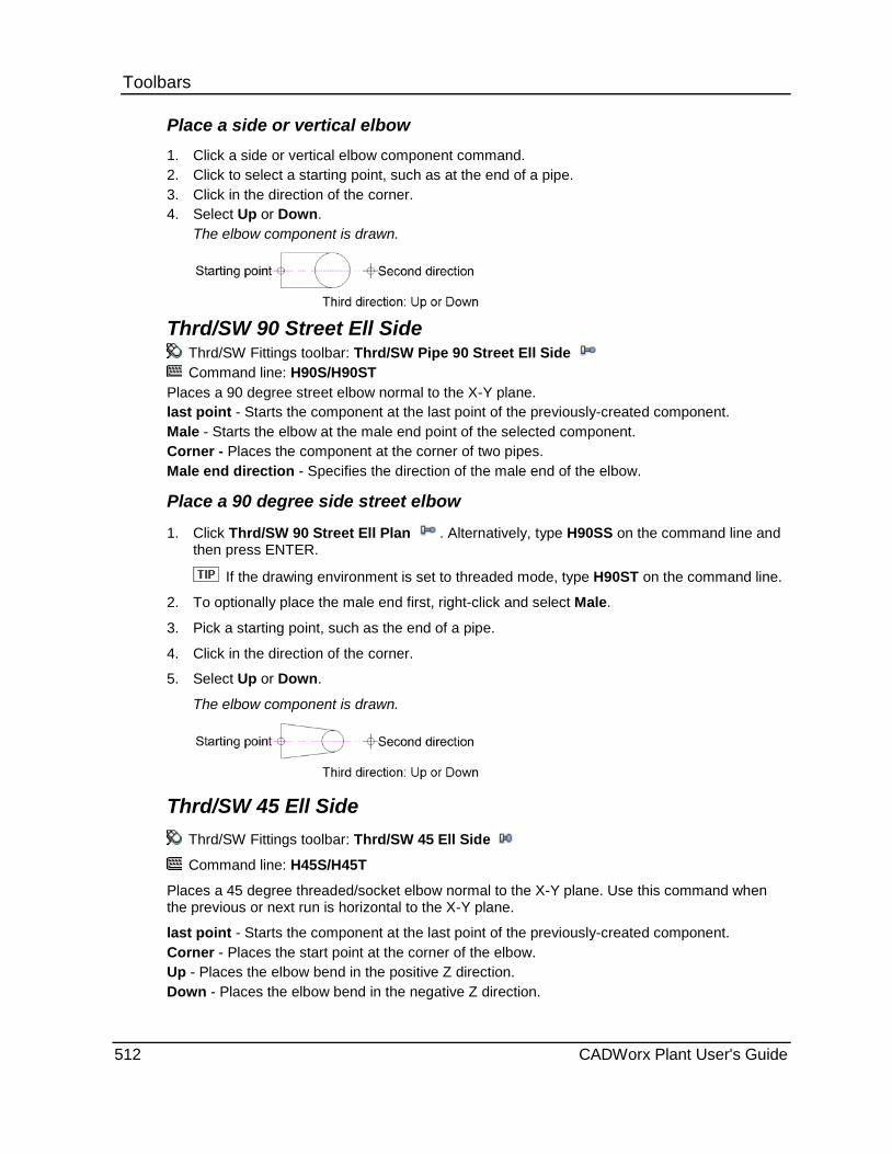
Toolbars Place a side or vertical elbow 1. Click a side or vertical elbow component command. 2. Click to select a starting point, such as at the end of a pipe. 3. Click in the direction of the corner. 4. Select Up or Down.
The elbow component is drawn.
Thrd/SW 90 Street Ell Side
Thrd/SW Fittings toolbar: Thrd/SW Pipe 90 Street Ell Side Command line: H90S/H90ST
Places a 90 degree street elbow normal to the X-Y plane. last point - Starts the component at the last point of the previously-created component. Male - Starts the elbow at the male end point of the selected component. Corner - Places the component at the corner of two pipes. Male end direction - Specifies the direction of the male end of the elbow.
Place a 90 degree side street elbow
1. Click Thrd/SW 90 Street Ell Plan . Alternatively, type H90SS on the command line and then press ENTER.
If the drawing environment is set to threaded mode, type H90ST on the command line.
2. To optionally place the male end first, right-click and select Male.
3. Pick a starting point, such as the end of a pipe.
4. Click in the direction of the corner.
5. Select Up or Down.
The elbow component is drawn.
Thrd/SW 45 Ell Side Thrd/SW Fittings toolbar: Thrd/SW 45 Ell Side
Command line: H45S/H45T
Places a 45 degree threaded/socket elbow normal to the X-Y plane. Use this command when the previous or next run is horizontal to the X-Y plane.
last point - Starts the component at the last point of the previously-created component. Corner - Places the start point at the corner of the elbow. Up - Places the elbow bend in the positive Z direction. Down - Places the elbow bend in the negative Z direction.
512 CADWorx Plant User's Guide

Toolbars Place a side or vertical elbow 1. Click a side or vertical elbow component command.
2. Click to select a starting point, such as at the end of a pipe.
3. Click in the direction of the corner.
4. Select Up or Down.
The elbow component is drawn.
Thrd/SW 45 Ell Vert Thrd/SW Fittings toolbar: Thrd/SW 45 Ell Vert
Command line: V45S/V45T
Places a 45 degree elbow normal to the X-Y plane. Use this command when the previous or next run is vertical to the X-Y plane.
last point - Starts the component at the last point of the previously-created component.
Corner - Places the start point at the corner of the elbow.
Up - Places the elbow bend in the positive Z direction.
Down - Places the elbow bend in the negative Z direction. Place a side or vertical elbow 1. Click a side or vertical elbow component command. 2. Click to select a starting point, such as at the end of a pipe. 3. Click in the direction of the corner. 4. Select Up or Down.
The elbow component is drawn.
Thrd/SW 90 Red Ell Side Thrd/SW Fittings toolbar: Thrd/SW 90 Red Ell Side
Command line: H90RS/H90RT
Places a 90 degree threaded/socket reducing elbow normal to the X-Y plane.
last point - Starts the component at the last point of the previously-created component.
Corner - Places the component at the corner of two pipes.
Small - Places the reducing end of the elbow at the start point.
Up - Places the elbow bend in the positive Z direction.
Down - Places the elbow bend in the negative Z direction.
CADWorx Plant User's Guide 513
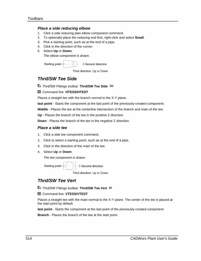
Toolbars Place a side reducing elbow 1. Click a side reducing plan elbow component command. 2. To optionally place the reducing end first, right-click and select Small. 3. Pick a starting point, such as at the end of a pipe. 4. Click in the direction of the corner. 5. Select Up or Down.
The elbow component is drawn.
Thrd/SW Tee Side Thrd/SW Fittings toolbar: Thrd/SW Tee Side
Command line: HTESS/HTEST
Places a straight tee with the branch normal to the X-Y plane.
last point - Starts the component at the last point of the previously-created component.
Middle - Places the tee at the centerline intersection of the branch and main of the tee.
Up - Places the branch of the tee in the positive Z direction.
Down - Places the branch of the tee in the negative Z direction.
Place a side tee 1. Click a side tee component command.
2. Click to select a starting point, such as at the end of a pipe.
3. Click in the direction of the main of the tee.
4. Select Up or Down.
The tee component is drawn.
Thrd/SW Tee Vert Thrd/SW Fittings toolbar: Thrd/SW Tee Vert
Command line: VTESS/VTEST
Places a straight tee with the main normal to the X-Y plane. The center of the tee is placed at the start point by default.
last point - Starts the component at the last point of the previously-created component.
Branch - Places the branch of the tee at the start point.
514 CADWorx Plant User's Guide

Toolbars Place a vertical tee 1. Click a vertical tee component command.
2. Click to select a starting point, such as at the end of a pipe.
3. Click in the direction of the branch of the tee.
The tee component is drawn.
Thrd/SW Tee Red Side Thrd/SW Fittings toolbar: Thrd/SW Tee Red Side
Command line: HTERS/HTERT
Places a threaded/socket straight reducing tee with the branch normal to the X-Y plane.
last point - Starts the component at the last point of the previously-created component.
Middle - Places the tee at the centerline intersection of the branch and main of the tee.
Up - Places the branch of the tee in the positive Z direction.
Down - Places the branch of the tee in the negative Z direction.
Place a side tee 1. Click a side tee component command.
2. Click to select a starting point, such as at the end of a pipe.
3. Click in the direction of the main of the tee.
4. Select Up or Down.
The tee component is drawn.
Thrd/SW Tee Red Vert Thrd/SW Fittings toolbar: Thrd/SW Tee Red Vert
Command line: VTERS/VTERT
Places a straight reducing tee with the main normal to the X-Y plane. The center of the tee is placed at the start point by default.
last point - Starts the component at the last point of the previously-created component.
Branch - Places the branch of the tee at the start point.
CADWorx Plant User's Guide 515
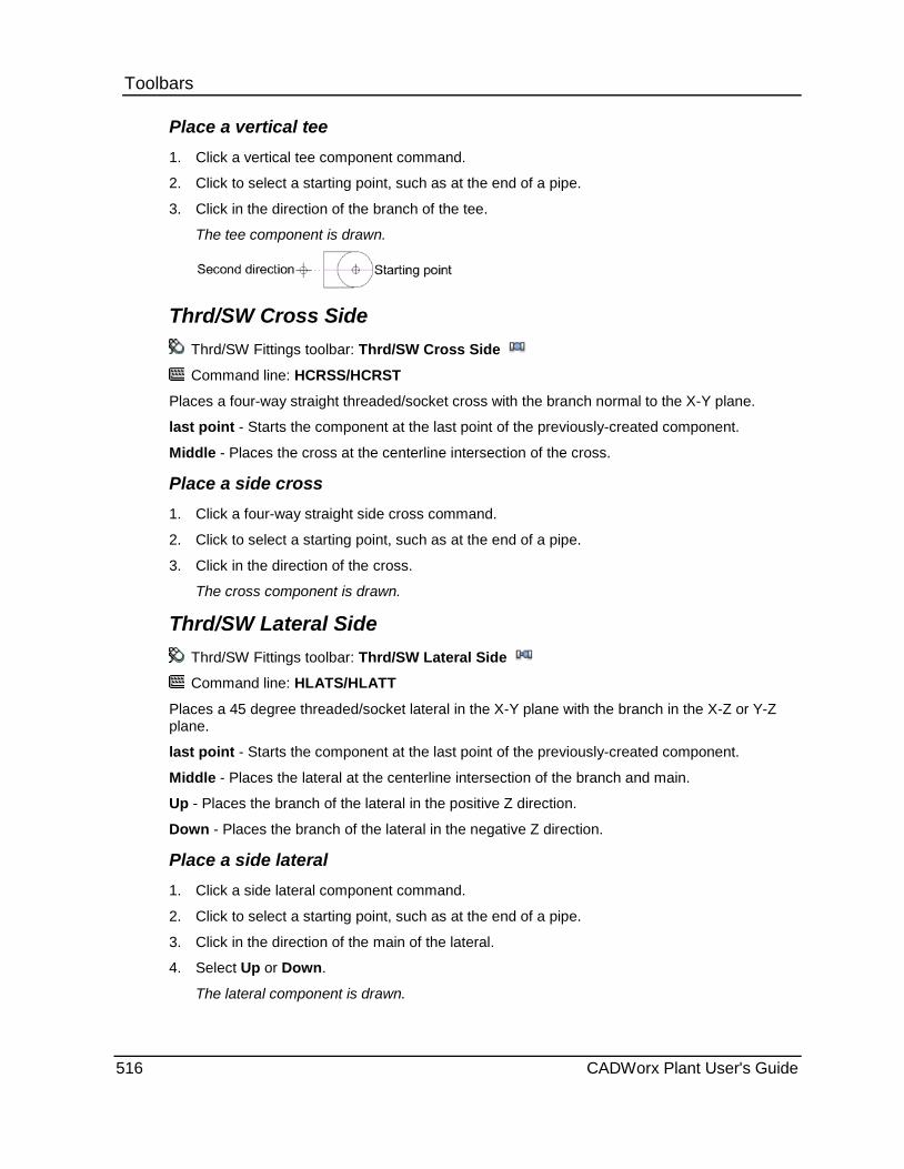
Toolbars Place a vertical tee 1. Click a vertical tee component command.
2. Click to select a starting point, such as at the end of a pipe.
3. Click in the direction of the branch of the tee.
The tee component is drawn.
Thrd/SW Cross Side Thrd/SW Fittings toolbar: Thrd/SW Cross Side
Command line: HCRSS/HCRST
Places a four-way straight threaded/socket cross with the branch normal to the X-Y plane.
last point - Starts the component at the last point of the previously-created component.
Middle - Places the cross at the centerline intersection of the cross.
Place a side cross 1. Click a four-way straight side cross command.
2. Click to select a starting point, such as at the end of a pipe.
3. Click in the direction of the cross.
The cross component is drawn.
Thrd/SW Lateral Side Thrd/SW Fittings toolbar: Thrd/SW Lateral Side
Command line: HLATS/HLATT
Places a 45 degree threaded/socket lateral in the X-Y plane with the branch in the X-Z or Y-Z plane.
last point - Starts the component at the last point of the previously-created component.
Middle - Places the lateral at the centerline intersection of the branch and main.
Up - Places the branch of the lateral in the positive Z direction.
Down - Places the branch of the lateral in the negative Z direction.
Place a side lateral 1. Click a side lateral component command.
2. Click to select a starting point, such as at the end of a pipe.
3. Click in the direction of the main of the lateral.
4. Select Up or Down.
The lateral component is drawn.
516 CADWorx Plant User's Guide

Toolbars Thrd/SW Lateral Vert
Thrd/SW Fittings toolbar: Thrd/SW Lateral Vert
Command line: VLATS/VLATT
Places a 45 degree threaded/socket lateral with the main normal to the X-Y plane. The center of the lateral is placed at the start point by default.
last point - Starts the component at the last point of the previously-created component.
Up - Places the branch of the lateral in the positive Z direction.
Down - Places the branch of the lateral in the negative Z direction.
Place a vertical lateral 1. Click a vertical lateral component command.
2. Click to select a starting point, such as at the end of a pipe.
3. Click in the direction of the branch of the lateral.
4. Select Up or Down.
The lateral component is drawn.
Thrd/SW Full Clpg End Thrd/SW Fittings toolbar: Thrd/SW Full Clpg End
Command line: VCPS/VCPT
Places a full coupling end normal to the X-Y plane.
last point - Starts the component at the last point of the previously-created component.
Up - Places the coupling in the positive Z direction.
Down - Places the coupling in the negative Z direction.
Place a coupling end 1. Click a coupling end component command.
2. Click to select a starting point, such as the end of a pipe.
3. Click to select the direction of the top of the coupling.
The coupling component is drawn.
Thrd/SW Half Clpg End Thrd/SW Fittings toolbar: Thrd/SW Half Clpg End
Command line: VHCPS/VHCPT
Places a half coupling end normal to the X-Y plane.
last point - Starts the component at the last point of the previously-created component.
Up - Places the coupling in the positive Z direction.
Down - Places the coupling in the negative Z direction.
CADWorx Plant User's Guide 517
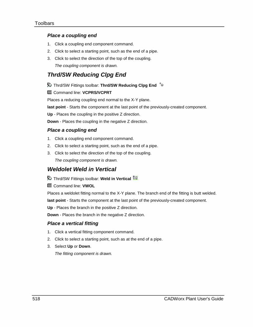
Toolbars Place a coupling end 1. Click a coupling end component command.
2. Click to select a starting point, such as the end of a pipe.
3. Click to select the direction of the top of the coupling.
The coupling component is drawn.
Thrd/SW Reducing Clpg End
Thrd/SW Fittings toolbar: Thrd/SW Reducing Clpg End
Command line: VCPRS/VCPRT
Places a reducing coupling end normal to the X-Y plane.
last point - Starts the component at the last point of the previously-created component.
Up - Places the coupling in the positive Z direction.
Down - Places the coupling in the negative Z direction.
Place a coupling end 1. Click a coupling end component command.
2. Click to select a starting point, such as the end of a pipe.
3. Click to select the direction of the top of the coupling.
The coupling component is drawn.
Weldolet Weld in Vertical Thrd/SW Fittings toolbar: Weld in Vertical
Command line: VWOL
Places a weldolet fitting normal to the X-Y plane. The branch end of the fitting is butt welded.
last point - Starts the component at the last point of the previously-created component.
Up - Places the branch in the positive Z direction.
Down - Places the branch in the negative Z direction.
Place a vertical fitting 1. Click a vertical fitting component command.
2. Click to select a starting point, such as at the end of a pipe.
3. Select Up or Down.
The fitting component is drawn.
518 CADWorx Plant User's Guide

Toolbars Threadolet Thread in Vertical
Thrd/SW Fittings toolbar: Thrd in Vertical
Command line: VTOL
Places a threadolet fitting normal to the X-Y plane. The branch end of the fitting is threaded.
last point - Starts the component at the last point of the previously-created component.
Up - Places the branch in the positive Z direction.
Down - Places the branch in the negative Z direction.
Place a vertical fitting 1. Click a vertical fitting component command.
2. Click to select a starting point, such as at the end of a pipe.
3. Select Up or Down.
The fitting component is drawn.
Sockolet Socket Weld in Vertical Thrd/SW Fittings toolbar: SW in Vertical
Command line: VSOL
Places a sockolet fitting normal to the X-Y plane. The branch end of the fitting is socket welded.
last point - Starts the component at the last point of the previously-created component.
Up - Places the branch in the positive Z direction.
Down - Places the branch in the negative Z direction.
Place a vertical fitting 1. Click a vertical fitting component command.
2. Click to select a starting point, such as at the end of a pipe.
3. Select Up or Down.
The fitting component is drawn.
Elbowlet Weld in Side Thrd/SW Fittings toolbar: EOL-Weld in Side
Command line: HEOLW
Places an elbowlet fitting with in the X-Y plane on a side elbow. The branch end of the fitting is butt welded.
last point - Starts the component at the last point of the previously-created component.
Up - Places the branch in the positive Z direction.
Down - Places the branch in the negative Z direction.
CADWorx Plant User's Guide 519

Toolbars Place a side elbowlet fitting 1. Click a side elbowlet component command.
2. Click to select a starting point, such as at the end of a pipe.
3. Click in the direction of the branch end of the fitting.
4. Select Up or Down.
The fitting component is drawn.
Elbowlet Weld in Vertical Thrd/SW Fittings toolbar: EOL-Weld in Vert
Command line: VEOLW
Places an elbowlet fitting normal to the X-Y plane on a side elbow. The branch end of the fitting is butt welded.
last point - Starts the component at the last point of the previously-created component.
Place a vertical elbowlet fitting 1. Click a plan fitting component command.
2. Pick a starting point, such as at the end of a pipe.
3. Click in the direction of the buttweld end of the fitting.
The fitting component is drawn.
Elbowlet Thread in Side Thrd/SW Fittings toolbar: EOL-Thrd in Side
Command line: HEOLT
Places an elbowlet fitting with in the X-Y plane on a side elbow. The branch end of the fitting is threaded.
last point - Starts the component at the last point of the previously-created component.
Up - Places the branch in the positive Z direction.
Down - Places the branch in the negative Z direction.
Place a side elbowlet fitting 1. Click a side elbowlet component command.
2. Click to select a starting point, such as at the end of a pipe.
3. Click in the direction of the branch end of the fitting.
4. Select Up or Down.
The fitting component is drawn.
520 CADWorx Plant User's Guide

Toolbars Elbowlet Thread in Vertical
Thrd/SW Fittings toolbar: EOL-Thrd in Vert
Command line: VEOLT
Places an elbowlet fitting normal to the X-Y plane on a side elbow. The branch end of the fitting is threaded.
last point - Starts the component at the last point of the previously-created component.
Place a vertical elbowlet fitting 1. Click a plan fitting component command.
2. Pick a starting point, such as at the end of a pipe.
3. Click in the direction of the buttweld end of the fitting.
The fitting component is drawn.
Elbowlet Socket Weld in Side Thrd/SW Fittings toolbar: EOL-SW in Side
Command line: HEOLS
Places an elbowlet fitting with in the X-Y plane on a side elbow. The branch end of the fitting is socket welded.
last point - Starts the component at the last point of the previously-created component.
Up - Places the branch in the positive Z direction.
Down - Places the branch in the negative Z direction.
Place a side elbowlet fitting 1. Click a side elbowlet component command.
2. Click to select a starting point, such as at the end of a pipe.
3. Click in the direction of the branch end of the fitting.
4. Select Up or Down.
The fitting component is drawn.
Elbowlet Socket Weld in Vertical Thrd/SW Fittings toolbar: EOL-SW in Vert
Command line: VEOLS
Places an elbowlet fitting normal to the X-Y plane on a side elbow. The branch end of the fitting is socket welded.
last point - Starts the component at the last point of the previously-created component.
CADWorx Plant User's Guide 521
Toolbars Place a vertical elbowlet fitting 1. Click a plan fitting component command.
2. Pick a starting point, such as at the end of a pipe.
3. Click in the direction of the buttweld end of the fitting.
The fitting component is drawn.
Latrolet Weld in Side Thrd/SW Fittings toolbar: LOL-Weld in Side Command line: HLOLW
Places a lateral fitting 45 degrees out of the X-Y plane. The branch end of the fitting is butt welded.
last point - Starts the component at the last point of the previously-created component.
Up - Places the branch in the positive Z direction.
Down - Places the branch in the negative Z direction.
Place a side latrolet fitting 1. Click a side latrolet component command.
2. Click to select a starting point, such as at the end of a pipe.
3. Click in the direction of the branch end of the fitting.
4. Select Up or Down.
The fitting component is drawn.
Latrolet Thread in Side Thrd/SW Fittings toolbar: LOL-Thrd in Side
Command line: HLOLT
Places a lateral fitting 45 degrees out of the X-Y plane. The branch end of the fitting is threaded.
last point - Starts the component at the last point of the previously-created component.
Up - Places the branch in the positive Z direction.
Down - Places the branch in the negative Z direction.
Place a side latrolet fitting 1. Click a side latrolet component command.
2. Click to select a starting point, such as at the end of a pipe.
3. Click in the direction of the branch end of the fitting.
4. Select Up or Down.
The fitting component is drawn.
522 CADWorx Plant User's Guide

Toolbars Latrolet Socket Weld in Side
Thrd/SW Fittings toolbar: LOL-SW in Side
Command line: HLOLS
Places a lateral fitting 45 degrees out of the X-Y plane. The branch end of the fitting is socket welded.
last point - Starts the component at the last point of the previously-created component.
Up - Places the branch in the positive Z direction.
Down - Places the branch in the negative Z direction.
Place a side latrolet fitting 1. Click a side latrolet component command.
2. Click to select a starting point, such as at the end of a pipe.
3. Click in the direction of the branch end of the fitting.
4. Select Up or Down.
The fitting component is drawn.
Nipolet Weld in Vertical Thrd/SW Fittings toolbar: Weld in Vertical
Command line: VNOLP
Places a nipolet fitting normal to the X-Y plane. The branch end of the fitting is butt welded.
last point - Starts the component at the last point of the previously-created component.
Up - Places the branch in the positive Z direction.
Down - Places the branch in the negative Z direction.
Place a vertical fitting 1. Click a vertical fitting component command.
2. Click to select a starting point, such as at the end of a pipe.
3. Select Up or Down.
The fitting component is drawn.
Nipolet Thread in Vertical Thrd/SW Fittings toolbar: Thrd in Vertical
Command line: VNOLP
Places a nipolet fitting normal to the X-Y plane. The branch end of the fitting is threaded.
last point - Starts the component at the last point of the previously-created component.
Up - Places the branch in the positive Z direction.
Down - Places the branch in the negative Z direction.
CADWorx Plant User's Guide 523
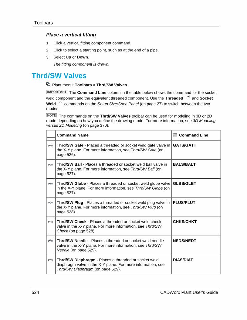
Toolbars Place a vertical fitting 1. Click a vertical fitting component command.
2. Click to select a starting point, such as at the end of a pipe.
3. Select Up or Down.
The fitting component is drawn.
Thrd/SW Valves Plant menu: Toolbars > Thrd/SW Valves
The Command Line column in the table below shows the command for the socket weld component and the equivalent threaded component. Use the Threaded and Socket Weld commands on the Setup Size/Spec Panel (on page 27) to switch between the two modes.
The commands on the Thrd/SW Valves toolbar can be used for modeling in 3D or 2D mode depending on how you define the drawing mode. For more information, see 3D Modeling versus 2D Modeling (on page 370).
Command Name Command Line
Thrd/SW Gate - Places a threaded or socket weld gate valve in the X-Y plane. For more information, see Thrd/SW Gate (on page 526).
GATS/GATT
Thrd/SW Ball - Places a threaded or socket weld ball valve in the X-Y plane. For more information, see Thrd/SW Ball (on page 527).
BALS/BALT
Thrd/SW Globe - Places a threaded or socket weld globe valve in the X-Y plane. For more information, see Thrd/SW Globe (on page 527).
GLBS/GLBT
Thrd/SW Plug - Places a threaded or socket weld plug valve in the X-Y plane. For more information, see Thrd/SW Plug (on page 528).
PLUS/PLUT
Thrd/SW Check - Places a threaded or socket weld check valve in the X-Y plane. For more information, see Thrd/SW Check (on page 528).
CHKS/CHKT
Thrd/SW Needle - Places a threaded or socket weld needle valve in the X-Y plane. For more information, see Thrd/SW Needle (on page 529).
NEDS/NEDT
Thrd/SW Diaphragm - Places a threaded or socket weld diaphragm valve in the X-Y plane. For more information, see Thrd/SW Diaphragm (on page 529).
DIAS/DIAT
524 CADWorx Plant User's Guide
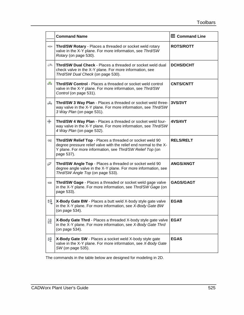
Toolbars Command Name Command Line
Thrd/SW Rotary - Places a threaded or socket weld rotary valve in the X-Y plane. For more information, see Thrd/SW Rotary (on page 530).
ROTS/ROTT
Thrd/SW Dual Check - Places a threaded or socket weld dual check valve in the X-Y plane. For more information, see Thrd/SW Dual Check (on page 530).
DCHS/DCHT
Thrd/SW Control - Places a threaded or socket weld control valve in the X-Y plane. For more information, see Thrd/SW Control (on page 531).
CNTS/CNTT
Thrd/SW 3 Way Plan - Places a threaded or socket weld three-way valve in the X-Y plane. For more information, see Thrd/SW 3 Way Plan (on page 531).
3VS/3VT
Thrd/SW 4 Way Plan - Places a threaded or socket weld four-way valve in the X-Y plane. For more information, see Thrd/SW 4 Way Plan (on page 532).
4VS/4VT
Thrd/SW Relief Top - Places a threaded or socket weld 90 degree pressure relief valve with the relief end normal to the X-Y plane. For more information, see Thrd/SW Relief Top (on page 537).
RELS/RELT
Thrd/SW Angle Top - Places a threaded or socket weld 90 degree angle valve in the X-Y plane. For more information, see Thrd/SW Angle Top (on page 533).
ANGS/ANGT
Thrd/SW Gage - Places a threaded or socket weld gage valve in the X-Y plane. For more information, see Thrd/SW Gage (on page 533).
GAGS/GAGT
X-Body Gate BW - Places a butt weld X-body style gate valve in the X-Y plane. For more information, see X-Body Gate BW (on page 534).
EGAB
X-Body Gate Thrd - Places a threaded X-body style gate valve in the X-Y plane. For more information, see X-Body Gate Thrd (on page 534).
EGAT
X-Body Gate SW - Places a socket weld X-body style gate valve in the X-Y plane. For more information, see X-Body Gate SW (on page 535).
EGAS
The commands in the table below are designed for modeling in 2D.
CADWorx Plant User's Guide 525

Toolbars Command Name Command Line
Thrd/SW 3 Way Side - Places a threaded or socket weld three-way valve with the valve branch normal to the X-Y plane. For more information, see Thrd/SW 3 Way Side (on page 535).
H3VS/H3VT
Thrd/SW 3 Way Vertical - Places a threaded or socket weld three-way valve with the main normal to the X-Y plane. For more information, see Thrd/SW 3 Way Vertical (on page 536).
V3VS/V3VT
Thrd/SW 4 Way Side - Places a threaded or socket weld four-way valve with the valve branches normal to the X-Y plane. For more information, see Thrd/SW 4 Way Side (on page 536).
H4VS/H4VT
Thrd/SW Relief Side - Places a threaded or socket weld 90 degree relief valve in the X-Y plane. For more information, see Thrd/SW Relief Side (on page 532).
HRELS/HRELT
Thrd/SW Pressure Top - Places a threaded or socket weld 90 degree pressure relief valve with the pressure end normal to the X-Y plane. For more information, see Thrd/SW Pressure Top.
VRELS/VRELT
Thrd/SW Angle Side - Places a threaded or socket weld angle valve in the X-Y plane. For more information, see Thrd/SW Angle Side (on page 537).
HANGS/HANGT
The arrow in the lower right corner of a command button indicates a fly-out menu with additional commands available.
Modeling in 3D These commands are useful for 3D modeling. All of the following commands are available in 3D and 2D modeling.
Thrd/SW Gate Thrd/SW Valves toolbar: Thrd/SW Gate Command line: GATS/GATT
Places a threaded or socket weld gate valve in the X-Y plane. last point - Starts the plain end of the valve at the last point of the previously-created component. Middle - Places the valve at its center.
526 CADWorx Plant User's Guide
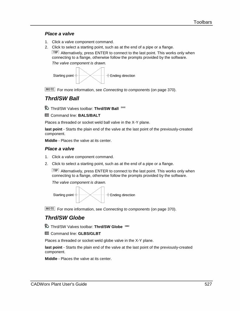
Toolbars Place a valve 1. Click a valve component command. 2. Click to select a starting point, such as at the end of a pipe or a flange.
Alternatively, press ENTER to connect to the last point. This works only when connecting to a flange, otherwise follow the prompts provided by the software. The valve component is drawn.
For more information, see Connecting to components (on page 370).
Thrd/SW Ball
Thrd/SW Valves toolbar: Thrd/SW Ball
Command line: BALS/BALT
Places a threaded or socket weld ball valve in the X-Y plane.
last point - Starts the plain end of the valve at the last point of the previously-created component.
Middle - Places the valve at its center.
Place a valve 1. Click a valve component command.
2. Click to select a starting point, such as at the end of a pipe or a flange.
Alternatively, press ENTER to connect to the last point. This works only when connecting to a flange, otherwise follow the prompts provided by the software.
The valve component is drawn.
For more information, see Connecting to components (on page 370).
Thrd/SW Globe Thrd/SW Valves toolbar: Thrd/SW Globe
Command line: GLBS/GLBT
Places a threaded or socket weld globe valve in the X-Y plane.
last point - Starts the plain end of the valve at the last point of the previously-created component.
Middle - Places the valve at its center.
CADWorx Plant User's Guide 527
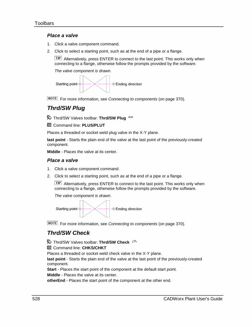
Toolbars Place a valve 1. Click a valve component command.
2. Click to select a starting point, such as at the end of a pipe or a flange.
Alternatively, press ENTER to connect to the last point. This works only when connecting to a flange, otherwise follow the prompts provided by the software.
The valve component is drawn.
For more information, see Connecting to components (on page 370).
Thrd/SW Plug Thrd/SW Valves toolbar: Thrd/SW Plug
Command line: PLUS/PLUT
Places a threaded or socket weld plug valve in the X-Y plane.
last point - Starts the plain end of the valve at the last point of the previously-created component.
Middle - Places the valve at its center.
Place a valve 1. Click a valve component command.
2. Click to select a starting point, such as at the end of a pipe or a flange.
Alternatively, press ENTER to connect to the last point. This works only when connecting to a flange, otherwise follow the prompts provided by the software.
The valve component is drawn.
For more information, see Connecting to components (on page 370).
Thrd/SW Check Thrd/SW Valves toolbar: Thrd/SW Check Command line: CHKS/CHKT
Places a threaded or socket weld check valve in the X-Y plane. last point - Starts the plain end of the valve at the last point of the previously-created component. Start - Places the start point of the component at the default start point. Middle - Places the valve at its center. otherEnd - Places the start point of the component at the other end.
528 CADWorx Plant User's Guide

Toolbars Place a valve 1. Click a valve component command.
2. Click to select a starting point, such as at the end of a pipe or a flange.
Alternatively, press ENTER to connect to the last point. This works only when connecting to a flange, otherwise follow the prompts provided by the software.
The valve component is drawn.
For more information, see Connecting to components (on page 370).
Thrd/SW Needle Thrd/SW Valves toolbar: Thrd/SW Needle
Command line: NEDS/NEDT
Places a threaded or socket weld needle valve in the X-Y plane.
last point - Starts the plain end of the valve at the last point of the previously-created component.
Middle - Places the valve at its center.
Place a valve 1. Click a valve component command.
2. Click to select a starting point, such as at the end of a pipe or a flange.
Alternatively, press ENTER to connect to the last point. This works only when connecting to a flange, otherwise follow the prompts provided by the software.
The valve component is drawn.
For more information, see Connecting to components (on page 370).
Thrd/SW Diaphragm Thrd/SW Valves toolbar: Thrd/SW Diaphragm
Command line: DIAS/DIAT
Places a threaded or socket weld diaphragm valve in the X-Y plane.
last point - Starts the plain end of the valve at the last point of the previously-created component.
Middle - Places the valve at its center.
CADWorx Plant User's Guide 529

Toolbars Place a valve 1. Click a valve component command.
2. Click to select a starting point, such as at the end of a pipe or a flange.
Alternatively, press ENTER to connect to the last point. This works only when connecting to a flange, otherwise follow the prompts provided by the software.
The valve component is drawn.
For more information, see Connecting to components (on page 370).
Thrd/SW Rotary Thrd/SW Valves toolbar: Thrd/SW Rotary
Command line: ROTS/ROTT
Places a threaded or socket weld rotary valve in the X-Y plane.
last point - Starts the plain end of the valve at the last point of the previously-created component.
Middle - Places the valve at its center.
Place a valve 1. Click a valve component command.
2. Click to select a starting point, such as at the end of a pipe or a flange.
Alternatively, press ENTER to connect to the last point. This works only when connecting to a flange, otherwise follow the prompts provided by the software.
The valve component is drawn.
For more information, see Connecting to components (on page 370).
Thrd/SW Dual Check Thrd/SW Valves toolbar: Thrd/SW Dual Check Command line: DCHS/DCHT
Places a threaded or socket weld dual check valve in the X-Y plane. last point - Starts the plain end of the valve at the last point of the previously-created component. Start - Places the start point of the component at the default start point. Middle - Places the valve at its center. otherEnd - Places the start point of the component at the other end.
530 CADWorx Plant User's Guide
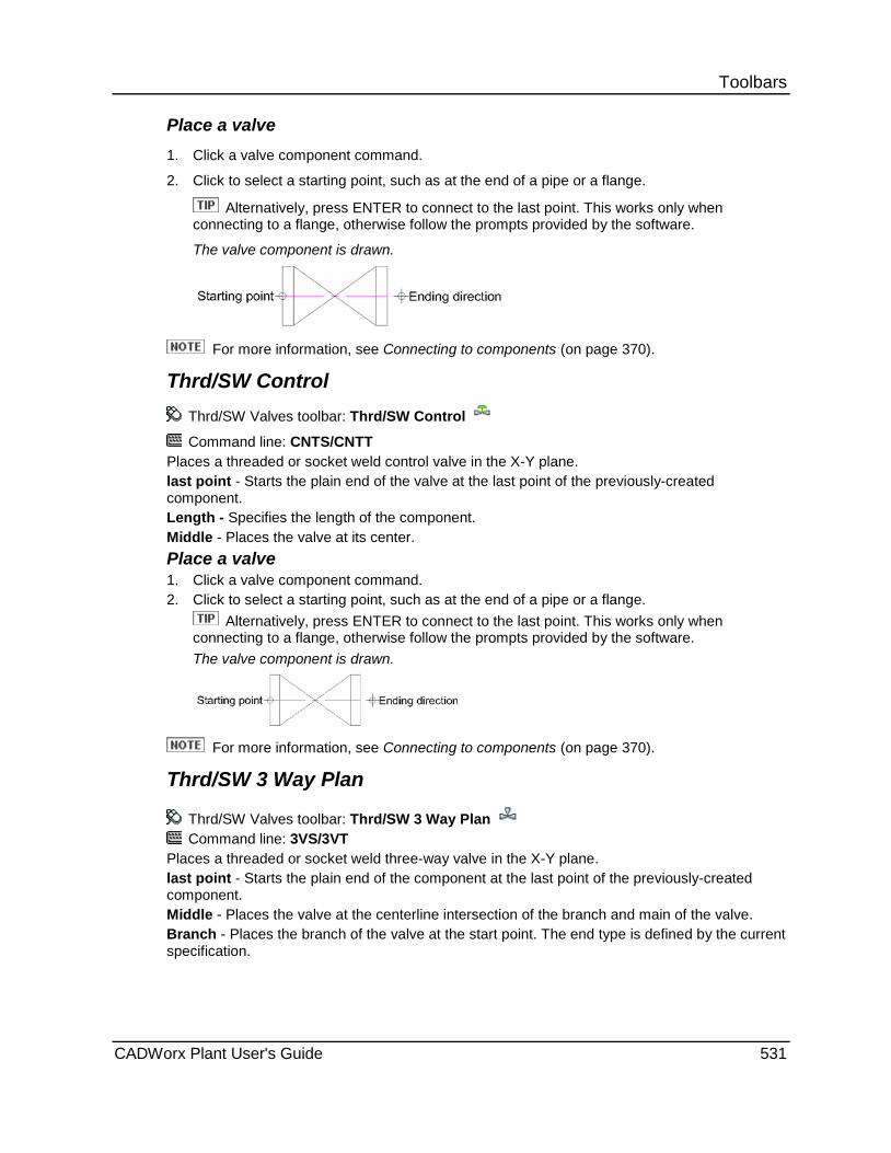
Toolbars Place a valve 1. Click a valve component command.
2. Click to select a starting point, such as at the end of a pipe or a flange.
Alternatively, press ENTER to connect to the last point. This works only when connecting to a flange, otherwise follow the prompts provided by the software.
The valve component is drawn.
For more information, see Connecting to components (on page 370).
Thrd/SW Control Thrd/SW Valves toolbar: Thrd/SW Control
Command line: CNTS/CNTT Places a threaded or socket weld control valve in the X-Y plane. last point - Starts the plain end of the valve at the last point of the previously-created component. Length - Specifies the length of the component. Middle - Places the valve at its center. Place a valve 1. Click a valve component command. 2. Click to select a starting point, such as at the end of a pipe or a flange.
Alternatively, press ENTER to connect to the last point. This works only when connecting to a flange, otherwise follow the prompts provided by the software. The valve component is drawn.
For more information, see Connecting to components (on page 370).
Thrd/SW 3 Way Plan
Thrd/SW Valves toolbar: Thrd/SW 3 Way Plan Command line: 3VS/3VT
Places a threaded or socket weld three-way valve in the X-Y plane. last point - Starts the plain end of the component at the last point of the previously-created component. Middle - Places the valve at the centerline intersection of the branch and main of the valve. Branch - Places the branch of the valve at the start point. The end type is defined by the current specification.
CADWorx Plant User's Guide 531

Toolbars Place a 3-way plan valve 1. Click a three-way valve command.
2. Click to select a starting point, such as at the end of a pipe or a flange. Alternatively, press ENTER to connect to the last point and skip the next step.
3. Click in the direction of the main of the valve. This prompt only appears when you are not connecting to a component in the model.
4. Click in the direction of the branch of the valve. The valve component is drawn.
Thrd/SW 4 Way Plan
Thrd/SW Valves toolbar: Thrd/SW 4 Way Plan Command line: 4VS/4VT
Places a threaded or socket weld four-way valve in the X-Y plane. last point - Starts the plain end of the component at the last point of the previously-created component. Middle - Places the valve at the centerline intersection of the branch and main of the valve. Place a 4-way plan valve 1. Click a four-way plan valve command. 2. Click to select a starting point, such as at the end of a pipe or a flange. Alternatively, press
ENTER to connect to the last point. 3. Click in the direction of the valve.
The valve component is drawn.
Thrd/SW Relief Side
Thrd/SW Valves toolbar: Thrd/SW Relief Side
Command line: RELS/RELT Places a threaded or socket weld 90 degree relief valve in the X-Y plane. last point - Starts the component at the last point of the previously-created component. Length - Defines the length of the pressure side and the relief side of the valve. Corner - Places the component at the corner of two pipes. Relief - Places the relief end of the valve at the start point. Pressure - Places the pressure end of the valve at the start point.
532 CADWorx Plant User's Guide
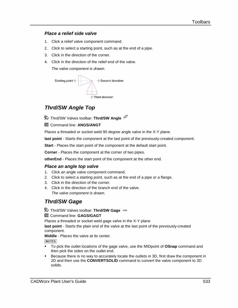
Toolbars Place a relief side valve 1. Click a relief valve component command.
2. Click to select a starting point, such as at the end of a pipe.
3. Click in the direction of the corner.
4. Click in the direction of the relief end of the valve.
The valve component is drawn.
Thrd/SW Angle Top
Thrd/SW Valves toolbar: Thrd/SW Angle
Command line: ANGS/ANGT
Places a threaded or socket weld 90 degree angle valve in the X-Y plane.
last point - Starts the component at the last point of the previously-created component.
Start - Places the start point of the component at the default start point.
Corner - Places the component at the corner of two pipes.
otherEnd - Places the start point of the component at the other end.
Place an angle top valve 1. Click an angle valve component command. 2. Click to select a starting point, such as at the end of a pipe or a flange. 3. Click in the direction of the corner. 4. Click in the direction of the branch end of the valve.
The valve component is drawn.
Thrd/SW Gage Thrd/SW Valves toolbar: Thrd/SW Gage Command line: GAGS/GAGT
Places a threaded or socket weld gage valve in the X-Y plane last point - Starts the plain end of the valve at the last point of the previously-created component. Middle - Places the valve at its center.
To pick the outlet locations of the gage valve, use the MIDpoint of OSnap command and
then pick the sides on the outlet end. Because there is no way to accurately locate the outlets in 3D, first draw the component in
2D and then use the CONVERTSOLID command to convert the valve component to 3D solids.
CADWorx Plant User's Guide 533
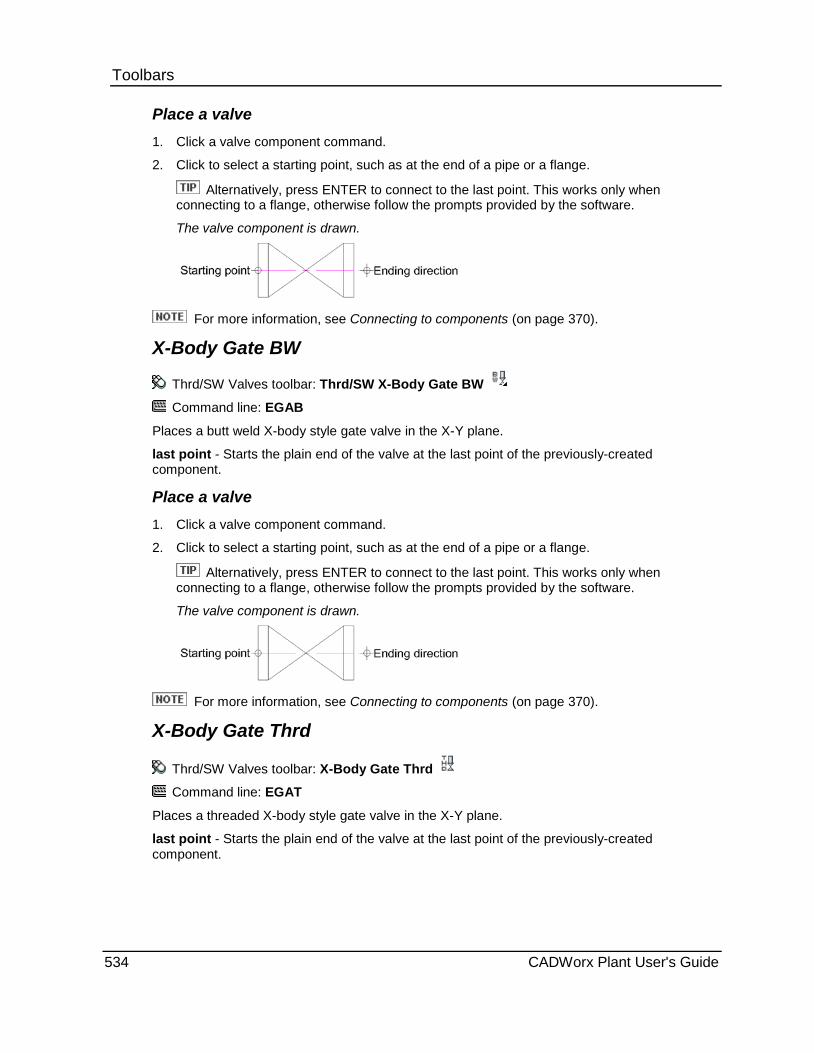
Toolbars Place a valve 1. Click a valve component command.
2. Click to select a starting point, such as at the end of a pipe or a flange.
Alternatively, press ENTER to connect to the last point. This works only when connecting to a flange, otherwise follow the prompts provided by the software.
The valve component is drawn.
For more information, see Connecting to components (on page 370).
X-Body Gate BW
Thrd/SW Valves toolbar: Thrd/SW X-Body Gate BW
Command line: EGAB
Places a butt weld X-body style gate valve in the X-Y plane.
last point - Starts the plain end of the valve at the last point of the previously-created component.
Place a valve 1. Click a valve component command.
2. Click to select a starting point, such as at the end of a pipe or a flange.
Alternatively, press ENTER to connect to the last point. This works only when connecting to a flange, otherwise follow the prompts provided by the software.
The valve component is drawn.
For more information, see Connecting to components (on page 370).
X-Body Gate Thrd
Thrd/SW Valves toolbar: X-Body Gate Thrd
Command line: EGAT
Places a threaded X-body style gate valve in the X-Y plane.
last point - Starts the plain end of the valve at the last point of the previously-created component.
534 CADWorx Plant User's Guide

Toolbars Place a valve 1. Click a valve component command. 2. Click to select a starting point, such as at the end of a pipe or a flange.
Alternatively, press ENTER to connect to the last point. This works only when connecting to a flange, otherwise follow the prompts provided by the software. The valve component is drawn.
For more information, see Connecting to components (on page 370).
X-Body Gate SW
Thrd/SW Valves toolbar: Thrd/SW X-Body Gate SW
Command line: EGAS
Places a socket weld X-body style gate valve in the X-Y plane.
last point - Starts the plain end of the valve at the last point of the previously-created component.
Place a valve 1. Click a valve component command. 2. Click to select a starting point, such as at the end of a pipe or a flange.
Alternatively, press ENTER to connect to the last point. This works only when connecting to a flange, otherwise follow the prompts provided by the software. The valve component is drawn.
For more information, see Connecting to components (on page 370).
Modeling in 2D Commands are designed for plotting in 2D. The views in these commands appear this way only in a 2D drawing.
Thrd/SW 3 Way Side Thrd/SW Valves toolbar: Thrd/SW 3 Way Side Command line: H3VS/H3VT
Places a threaded or socket weld three-way valve with the valve branch normal to the X-Y plane.
last point - Starts the plain end of the component at the last point of the previously-created component.
Middle - Places the valve at the centerline intersection of the branch and main of the valve.
CADWorx Plant User's Guide 535
Toolbars Place a 3-way side valve 1. Click a three-way side valve component command.
2. Click to select a starting point, such as at the end of a pipe or a flange.
3. Click in the direction of the main of the valve.
4. Select Up or Down.
The valve component is drawn.
Thrd/SW 3 Way Vertical Thrd/SW Valves toolbar: Thrd/SW 3 Way Vertical
Command line: V3VS/V3VT
Places a threaded or socket weld three-way valve with the main normal to the X-Y plane.
last point - Starts the plain end of the component at the last point of the previously-created component.
Middle - Places the valve at the centerline intersection of the branch and main of the valve.
Place a 3-way vertical valve 1. Click a three-way vertical valve component command.
2. Click to select a starting point, such as at the end of a pipe or a flange.
3. Click in the direction of the branch of the valve.
The valve component is drawn.
Thrd/SW 4 Way Side Thrd/SW Valves toolbar: Thrd/SW 4 Way Side Command line: H4VS/H4VT
Places a threaded or socket weld four-way valve with the valve branches normal to the X-Y plane. last point - Starts the plain end of the component at the last point of the previously-created component. Middle - Places the valve at the centerline intersection of the branch and main of the valve.
Place a 4-way side valve 1. Click a four-way side valve command. 2. Click to select a starting point, such as at the end of a pipe or a flange. 3. Click in the direction of the valve.
The valve component is drawn.
536 CADWorx Plant User's Guide
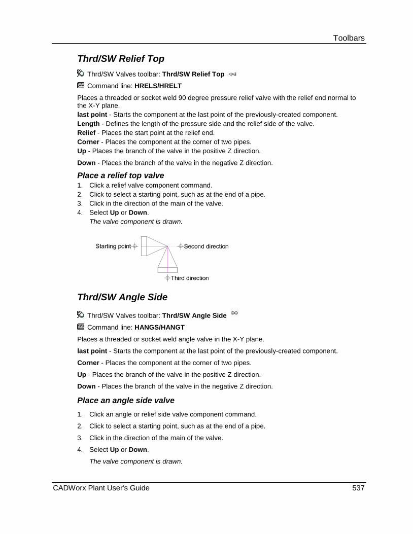
Toolbars Thrd/SW Relief Top
Thrd/SW Valves toolbar: Thrd/SW Relief Top
Command line: HRELS/HRELT
Places a threaded or socket weld 90 degree pressure relief valve with the relief end normal to the X-Y plane. last point - Starts the component at the last point of the previously-created component. Length - Defines the length of the pressure side and the relief side of the valve. Relief - Places the start point at the relief end. Corner - Places the component at the corner of two pipes. Up - Places the branch of the valve in the positive Z direction.
Down - Places the branch of the valve in the negative Z direction.
Place a relief top valve 1. Click a relief valve component command. 2. Click to select a starting point, such as at the end of a pipe. 3. Click in the direction of the main of the valve. 4. Select Up or Down.
The valve component is drawn.
Thrd/SW Angle Side
Thrd/SW Valves toolbar: Thrd/SW Angle Side
Command line: HANGS/HANGT
Places a threaded or socket weld angle valve in the X-Y plane.
last point - Starts the component at the last point of the previously-created component.
Corner - Places the component at the corner of two pipes.
Up - Places the branch of the valve in the positive Z direction.
Down - Places the branch of the valve in the negative Z direction.
Place an angle side valve 1. Click an angle or relief side valve component command.
2. Click to select a starting point, such as at the end of a pipe.
3. Click in the direction of the main of the valve.
4. Select Up or Down.
The valve component is drawn.
CADWorx Plant User's Guide 537

Toolbars
Gaskets, Etc. Plant menu: Toolbars > Gaskets, Etc.
Command Name Command Line
Tick Mark - Creates a dimension tick mark. For more information, see Tick Mark (on page 236).
TICK
Standard - Places standard stud bolts at the selected location. For more information, see Standard (on page 219).
STDBOLT
Non Standard - Places non standard stud bolts at the selected location. For more information, see Non Standard (on page 219).
NONSTDBOLT
Automatic - Sizes and places stud bolts automatically at each gasket. For more information, see Automatic (on page 216).
AUTOBOLT
Gasket - Places a gasket. For more information, see Gasket (on page 538).
GAS
Weld Gap - Creates weld gaps For more information, see Weld Gap (on page 539).
WELD
The arrow in the lower right corner of a command button indicates a fly-out menu with additional commands available.
Gasket Gaskets, Etc. toolbar: Gasket
Command line: GAS
Places a gasket. The gasket is composed of two different entities. First is an inserted block that is located at the insert point. Another inserted block is placed on the other side of the gasket. The GASR contains Xdata information for Bill of Materials extraction. GASL is a plain insert without information. When you use mode conversion to convert components to another mode in a Z-plane position, the GASL insert is destroyed. When you convert the single GASR insert in the proper X and Y planes, both sides of the gasket are created again. The shape of the gasket allows for other uses, as explained below. The half circle on the outer portion of both inserts allow for easy picking for dimensioning. For example, when dimensioning, select Osnap, CENter of, and pick the center of circle which is the exact corner of the face of flange). You should find that it is relatively easy to select the center of the circle from a zoomed out view. For placing a flange face against the gasket, you can select Osnap, ENDpoint of, and select the side of the gasket to place the flange perfectly in position. This provides a method of placing the flange when the last point option is no longer available. This routine is also used for ring type joints. The data files for rings have an extra column indicating the ring number. The gasket routine senses this additional column and adds this ring number to the bill of materials description. The distance between the faces of adjoining flanges (under compression) are used in this file instead of the actual depth of the ring.
538 CADWorx Plant User's Guide

Toolbars Insert a gasket
1. Click Gasket .
2. Click to select a starting point, such as the end of a pipe. Alternatively, press ENTER to select the last point of the previously-placed component.
3. Click in the required direction.
The software inserts a gasket at the selected location.
The same procedure can be used to place ring type joints. The data files for rings have an extra column, which indicates the ring number. The gasket routine senses this additional column, and adds this ring number to the Bill of Materials description. The distance between the faces of adjoining flanges (under compression) is used in this file instead of the actual depth of the ring.
You can set the software to automatically add Gaskets when needed by changing the Apply Gasket Insertion Rule (on page 51) in Piping Rules under Setup .
Weld Gap Gaskets, Etc. toolbar: Weld Gap
Command line: WELD
Creates weld gaps for detailed pipe fabrication. Weld gaps are controlled by the currently defined specification and are placed according to size and/or schedule.
last point - Places the weld gap at the last point of the previously-created component.
Each specification has data files that provide different thicknesses.
Define a weld gap
1. Click Weld Gap .
2. Click to select a starting point, such as the end of a pipe. Alternatively, press ENTER to select the last point of the previously-placed component.
3. Click in the required direction.
The software creates a weld gap.
Use Osnap > Insert and select any portion of the weld gap symbol to start a new pipe or component from the weld gap
You can set the software to automatically add Gaskets when needed by changing the Apply Weld Insertion Rule (on page 50) in Piping Rules under Setup .
CADWorx Plant User's Guide 539
Toolbars
Pipe Ends Plant menu: Toolbars > Pipe Ends
Command Name Command Line
Flange O.D. - Inserts a graphical representation of a flange O.D. For more information, see Flange O.D. (on page 253)
ENDFLG
Plain End - Inserts a graphical representation of the plain end of a pipe. For more information, see Plain End (on page 253).
ENDPLAIN
Hidden End - Inserts a graphical representation of the hidden end of a pipe. For more information, see Hidden End (on page 253).
ENDHIDDEN
Pipe End - Inserts a graphical representation of the pipe end of a pipe. For more information, see Pipe End (on page 254).
ENDPIPE
Restraints Plant menu: > Toolbars > Restraints
The types of restraints used with CADWorx Plant are listed in the table below.
Command Name Command Line
Translational - Creates a translational-type restraint. For more information, see Translational (on page 261).
TRANSLATIONAL
Anchor - Creates an anchor-type restraint. For more information, see Anchor (on page 262).
ANCHOR
Spring Hanger - Creates a spring hanger-type restraint. For more information, see Spring Hanger (on page 262).
SPRING
Rotational - Creates a rotational-type restraint. For more information, see Rotational (on page 263).
ROTATIONAL
Snubber - Creates a Snubber-type restraint. For more information, see Snubber (on page 263).
SNUBBER
Guide - Creates a Guide-type restraint. For more information, see Guide (on page 264).
GUIDE
The restraint is used in the bi-directional link with CAESAR II. The position of the restraint is important for the evaluation of the stress model within CAESAR II. For example, you can position a rotational restraint at any vector.
540 CADWorx Plant User's Guide

Toolbars Restraints appear on the drawing in a symbolic format. You can modify the symbol shape that appears on the output drawing by editing the restraint drawing file. These drawing files are delivered to the [Product Folder]\Support folder. If necessary, a restraint symbol can be re-drawn as a three-dimensional shape. In these instances, you must maintain the base of the restraint at 0,0,0 and the direction of the restraint at 0 degrees.
The CAESARIITolerance (on page 36) variable is useful when the bi-directional process
encounters a problem locating a restraint along a pipe line, especially if the pipe line is sloped.
All supports drawn using the Restraint commands in CADWorx Plant are exported as guides to ISOGEN. To export a different symbol to ISOGEN, use the ISOGEN Data dialog box (on page 73) to change the SKEY. Acceptable SKEY values are ANCH, DUCK, GUID, SKID, SPRG, and HANG. For information about the sample ISOGEN shapes used with these SKEYS, see the ISOGEN Symbol Keys Reference Guide, which is delivered as a PDF file to the [Product Folder]\ISOGEN\Isogen_Utils folder.
You can also use the ISOGEN Data dialog box to change the support direction.
Misc Plant menu: Toolbars > Misc
Use the Threaded and Socket Weld commands on the Setup Size/Spec Panel (on page 27) to switch between these two modes for SW/Thrd Plan and SW/Thrd Side.
The commands on the Misc toolbar can be used for modeling in 3D or 2D mode depending on how you define the drawing mode. For more information, see 3D Modeling versus 2D Modeling (on page 370).
Command Name Command Line
Flanged Plan - Places a flanged pipe component in the X-Y plane. For more information, see Flanged Plan (on page 543).
STRF
SW/Thrd Plan - Places a socket weld/ threaded strainer component in the X-Y plane. For more information, see SW/Thrd Plan (on page 544).
STRT
Create - Creates symmetrical or nonsymmetrical user shape components. For more information, see User Shapes (on page 176).
USERCREATE
User Shape 1 - Places user created shape 1 in the X-Y plane. For more information, see User Shapes (on page 176).
USE1
User Shape 2 - Places user created shape 2 in the X-Y plane. For more information, see User Shapes (on page 176).
USE2
User Shape 3 - Places user created shape 3 in the X-Y plane. For more information, see User Shapes (on page 176).
USE3
User Shape 4 - Places user created shape 4 in the X-Y plane. For more information, see User Shapes (on page 176).
USE4
CADWorx Plant User's Guide 541
Toolbars Command Name Command Line
User Shape 5 - Places user created shape 5 in the X-Y plane. For more information, see User Shapes (on page 176).
USE5
Bleed Ring - Places a bleed ring in the drawing in the X-Y plane. For more information, see Bleed Ring or Spacer (on page 544).
BLD
Spec Bld Side - Places a blind spectacle in the drawing normal to the X-Y plane. For more information, see Spectacle Blind Side (on page 545).
SPCT
Reinforcing Pad - Inserts information indicating a reinforcement pad. For more information, see Reinforcing Pad (on page 260).
REINFPAD
Reinforcing Saddle - Inserts information indicating a reinforcement saddle. For more information, see Reinforcing Saddle (on page 260).
REINFSAD
Expansion Joint - Places an expansion joint in the drawing in the X-Y plane. For more information, see Expansion Joint (on page 545).
EXPF
Rigid Element - Places a CAESAR II element in the drawing. For more information, see Rigid Element (on page 546).
ELEMENT
Generic Attach - Attaches information to any generic AutoCAD object in the drawing. For more information, see Generic Attach (on page 202).
GENERIC
Stop Sign - Places ISOGEN stop sign symbols in the drawing. For more information, see Stop Sign (on page 124).
STOPSIGN
The commands in the table below are designed for modeling in 2D.
Command Name Command Line
Flanged Side - Places a flanged pipe component normal to the X-Y plane. For more information, see Flanged Side (on page 546).
HSTRF
SW/Thrd Side - Places a socket weld/ threaded strainer component normal to the X-Y plane. For more information, see SW/Thrd Side (on page 547).
HSTRT
Spec Bld Vert - Places a blind spectacle with the main normal to the X-Y plane. For more information, see Spectacle Blind Vertical (on page 547).
VSPCT
The arrow in the lower right corner of the button indicates a flyout for more options.
542 CADWorx Plant User's Guide
Toolbars
Modeling in 3D These commands are useful for 3D modeling. All of the following commands are available in 3D and 2D modeling.
Flanged Plan Misc toolbar: Flanged Plan
Command line: STRF
Places a flanged pipe component in the X-Y plane.
last point - Starts the component at the last point of the previously-created component.
Length - Specifies the length of the component.
Length of basket side - Specifies the length of the basket side of the component.
otherEnd - Places the start point of the component at the other end.
Main end - Specifies the direction of the second point.
Branch end - Specifies the direction of the branch end of the pipe.
Place a plan flange pipe
1. Click Flanged Plan . Alternatively, type STRF, and press ENTER.
2. Type L for length, or press ENTER to connect to the last point. If you are entering the length, follow the prompts back to this step for the last point.
3. Select a main end direction.
4. Select branch direction.
The flanged plan pipe is placed.
Auto Routing from the strainer lateral 1. Select the strainer in the drawing.
2. Click the grip point to autoroute from the lateral.
The piping component list displays.
3. Select Pipe or Nipple.
The sizes list for the pipes or nipples displays.
4. Select the size.
The pipe or nipple displays in the drawing with a Tap Connection automatically added.
CADWorx Plant User's Guide 543

Toolbars SW/Thrd Plan
Misc toolbar: SW/Thrd Plan
Command line: STRT
Places a socket weld/threaded strainer component in the X-Y plane.
last point - Starts the component at the last point of the previously-created component.
Length - Specifies the length of the component.
Length of basket side - Specifies the length of the basket side of the component.
otherEnd - Place the start point of the component at the other end.
Main end - Specifies the direction of the second point.
Branch end - Specifies the direction of the branch end of the pipe.
Place a side socket weld threaded pipe
1. Click SW/Thrd Plan . Alternatively, type STRT, and press ENTER.
2. Type L for length, or press ENTER to connect to the last point. If you are entering the length, follow the prompts back to this step for the last point.
3. Select a main end direction.
4. Select branch direction.
The plan socket weld/threaded pipe is placed.
Bleed Ring or Spacer Misc toolbar: Bleed Ring
Lined toolbar: Lined Spacer
Command line: BLD
Places a bleed ring or spacer in the X-Y plane.
last point - Starts the component at the last point of the previously-created component.
Length - Specifies the length of the bleed ring.
Place a bleed ring
1. Click Bleed Ring . Alternatively, type BLD, and press ENTER.
2. Type L for length, or press ENTER to connect to the last point. If you are entering the length, follow the prompts back to this step for the last point.
3. Select a direction in the drawing.
The bleed ring is placed.
544 CADWorx Plant User's Guide

Toolbars Spectacle Blind Side
Misc toolbar: Spec Bld Side
Command line: SPCT
Places a blind spectacle normal to the X-Y plane.
last point - Starts the component at the last point of the previously-created component.
Open - Places the start point at the open end.
Close - Places the start point at the closed end.
Thickness - Specifies the thickness of the blind spectacle.
Place a side blind spectacle
1. Click Spec Bld Side . Alternatively, type SPCT, and press ENTER.
2. Type T for thickness, or press ENTER to connect to the last point. If you are entering the thickness, follow the prompts back to this step for the last point.
3. Select a direction in the drawing.
4. Select a direction in the drawing.
The side blind spectacle is placed.
Reinforcing Saddle Miscellaneous toolbar: Reinforcing Saddle
Command line: REINFSAD
Attaches a reinforcement saddle to a branch connection. On the drawing, the reinforcement saddle is represented by the alpha-identifier S. This symbolic letter has Xdata attached to it that is used in Bill of Material generation and with the CAESAR II bi-directional link.
For more information, see Insert a reinforcement saddle (on page 261).
Expansion Joint Misc toolbar: Expansion Joint
Command line: EXPF
Places an expansion joint in the X-Y plane.
last point - Starts the component at the last point of the previously-created component.
Length - Specifies the length of the expansion joint.
Place an expansion joint 1. Click Expansion Joint . Alternatively, type EXPF, and press ENTER. 2. Type L for length, or press ENTER to connect to the last point. If you are entering the
length, follow the prompts back to this step for the last point. 3. Select a direction in the drawing.
The expansion joint is placed.
CADWorx Plant User's Guide 545
Toolbars Rigid Element
Misc toolbar: Rigid Element
Command line: ELEMENT
Places a CAESAR II element in the drawing.
Used with CAESAR II (pipe stress analysis software) when a rigid component is required. This is convenient when using a rigid from the base of a pump to the pump discharge piping, or placing a rigid as a structural member that might be supporting the pipe.
When using the CAESAR II bi-directional link or importing a stress input file, rigids can be automatically placed. These rigids are used by the bi-directional link and should not be modified in any manner. They can be moved with a piping system, but they need to remain in their relative location. They are often used when the length of a CAESAR II component does not match the components contained within CADWorx.
These elements are represented with a polyline that has pointed ends. Specify where rigid elements display from the LayerByLineNumber (on page 39) configuration setting.
Place a rigid element 1. Click Rigid Element . Alternatively, type ELEMENT, and press ENTER. 2. Select a start point. 3. Select a second point.
The rigid element is placed.
Modeling in 2D Commands are designed for plotting in 2D. The views in these commands appear this way only in a 2D drawing.
Flanged Side Misc toolbar: Flanged Side Command line: HSTRF
Places a pipe component normal to the X-Y plane. last point - Starts the component at the last point of the previously-created component. Length - Specifies the length of the component. Length of basket side - Specifies the length of the basket side of the component. otherEnd - Places the start point of the component at the other end. Up - Places the branch in the positive Z direction. Down - Places the branch direction in the negative the Z direction.
Place a side flange pipe 1. Click Flanged Side . Alternatively, type HSTRF, and press ENTER.
2. Type L for length, or press ENTER to connect to the last point. If you are entering the length, follow the prompts back to this step for the last point.
3. Select a direction in the drawing.
4. Select Up or Down.
The side flanged pipe is placed.
546 CADWorx Plant User's Guide
Toolbars SW/Thrd Side
Misc toolbar: SW/Thrd Side
Command line: HSTRT
Places a socket weld/threaded strainer component normal to the X-Y plane.
last point - Starts the component at the last point of the previously-created component.
Length - Specifies the length of the component.
Length of basket side - Specifies the length of the basket side of the component.
otherEnd - Places the start point of the component at the other end.
Up - Places the branch in the positive Z direction.
Down - Places the branch in the negative Z direction.
Place a side socket weld/threaded pipe 1. Click SW/Thrd Side . Alternatively, type HSTRT, and press ENTER.
2. Type L for length, or press ENTER to connect to the last point. If you are entering the length, follow the prompts back to this step for the last point.
3. Select a direction in the drawing.
4. Select Up or Down.
The socket weld threaded pipe is placed.
Spectacle Blind Vertical Misc toolbar: Spec Bld Vert
Command line: VSPCT
Places a vertical blind spectacle side in the X-Y plane.
Open - Places the start point at the open end.
Close - Places the start point at the closed end.
Thickness - Specifies the thickness of the blind spectacle.
Place a vertical blind spectacle 1. Click Spec Bld Vert . Alternatively, type VSPCT, and press ENTER.
2. Type T for thickness, or press ENTER to connect to the last point. If you are entering the thickness, follow the prompts back to this step for the start point.
3. Select a point in the drawing.
4. Select Up or Down.
The blind spectacle is drawn.
CADWorx Plant User's Guide 547
Toolbars
Operators Plant menu: Toolbars > Operators
Command Name Command Line
Top Works Add - Adds top works to a valve already drawn in the model. For more information, see Top Works Add (on page 197).
TOPWORKSADD
Top Works Change - Changes the orientation of or deletes top works already associated with a valve. For more information, see Top Works Change (on page 198).
TOPWORKSCHANGE
Line Numbers Plant menu: Toolbars > Line Numbers
Command Name Command Line
Line Number Setup - Modifies any line number configuration. For more information, see Setup (on page 146).
NUMBERSETUP
Line Number Assign - Assigns new or different line numbers to existing components. For more information, see Assign (on page 149).
NUMBERASSIGN
Line Number Annotate - Labels components with existing line numbers. For more information, see Annotate (on page 150).
NUMBERANNOTATE
Line Number By - Sets the line number from one of three sources: a P&ID project, the current drawing, or a selected component. For more information, see Set (on page 147).
NUMBERSET
Line Number Count - Sets the present line number count value. For more information, see Count (on page 148).
NUMBERCOUNT
Line Number Increment - Increases the line number count value. For more information, see Increment (on page 149).
NUMBER+
Line Number Decrement - Decreases the line number count value. For more information, see Decrement (on page 149).
NUMBER-
548 CADWorx Plant User's Guide

Toolbars
UCS Plant menu: Toolbars > UCS
Command Name Command Line
Flat - Places the current user coordinate system in the flat position. For more information, see Flat (on page 267).
VIEWFLAT
North - Places the current user coordinate system in the north position. For more information, see North (on page 268).
VIEWNORTH
South - Places the current user coordinate system in the south position. For more information, see South (on page 269).
VIEWSOUTH
East - Places the current user coordinate system in the east position. For more information, see East (on page 270).
VIEWEAST
West - Places the current user coordinate system in the west position. For more information, see West (on page 269).
VIEWWEST
Next - Toggles through each of the Point and Shoot UCS positions. For more information, see UCS Next (on page 268).
UCSNEXT
UCS Object - Orients the UCS according to an object you select. For more information, see UCS Object (on page 270).
UCS
Compass - Displays a compass-type symbol that indicates the Point and Shoot orientation. For more information, see Compass (on page 268).
COMPASS
Steel Plant menu: Toolbars > Steel
Command Name Command Line
Wide Flange - Places a wide flange shape. For more information, see Wide Flange Shapes (on page 274).
WSHAPE
Channel - Places a channel shape. For more information, see Channel Shapes (on page 275).
CSHAPE
Angle - Places an angle shape. For more information, see Angle Shapes (on page 276).
LSHAPE
Double Angle - Places a double angle shape. For more information, see Angle Double Shape (on page 285).
2LSHAPE
CADWorx Plant User's Guide 549
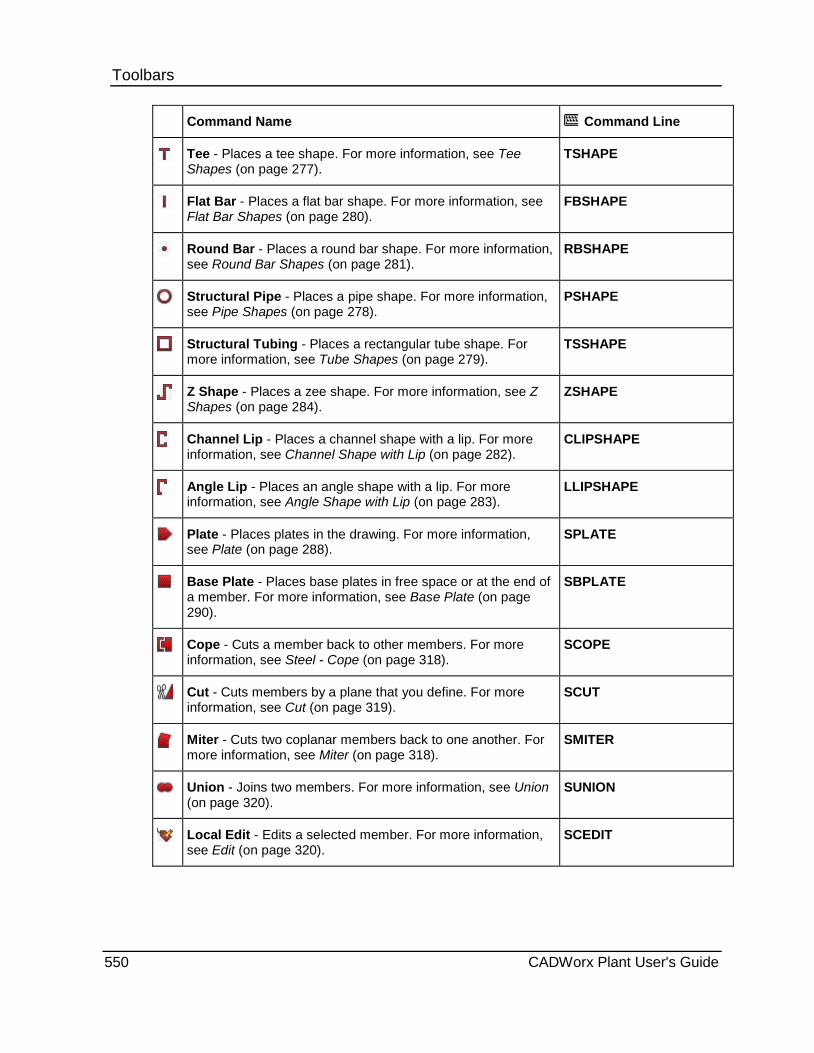
Toolbars Command Name Command Line
Tee - Places a tee shape. For more information, see Tee Shapes (on page 277).
TSHAPE
Flat Bar - Places a flat bar shape. For more information, see Flat Bar Shapes (on page 280).
FBSHAPE
Round Bar - Places a round bar shape. For more information, see Round Bar Shapes (on page 281).
RBSHAPE
Structural Pipe - Places a pipe shape. For more information, see Pipe Shapes (on page 278).
PSHAPE
Structural Tubing - Places a rectangular tube shape. For more information, see Tube Shapes (on page 279).
TSSHAPE
Z Shape - Places a zee shape. For more information, see Z Shapes (on page 284).
ZSHAPE
Channel Lip - Places a channel shape with a lip. For more information, see Channel Shape with Lip (on page 282).
CLIPSHAPE
Angle Lip - Places an angle shape with a lip. For more information, see Angle Shape with Lip (on page 283).
LLIPSHAPE
Plate - Places plates in the drawing. For more information, see Plate (on page 288).
SPLATE
Base Plate - Places base plates in free space or at the end of a member. For more information, see Base Plate (on page 290).
SBPLATE
Cope - Cuts a member back to other members. For more information, see Steel - Cope (on page 318).
SCOPE
Cut - Cuts members by a plane that you define. For more information, see Cut (on page 319).
SCUT
Miter - Cuts two coplanar members back to one another. For more information, see Miter (on page 318).
SMITER
Union - Joins two members. For more information, see Union (on page 320).
SUNION
Local Edit - Edits a selected member. For more information, see Edit (on page 320).
SCEDIT
550 CADWorx Plant User's Guide
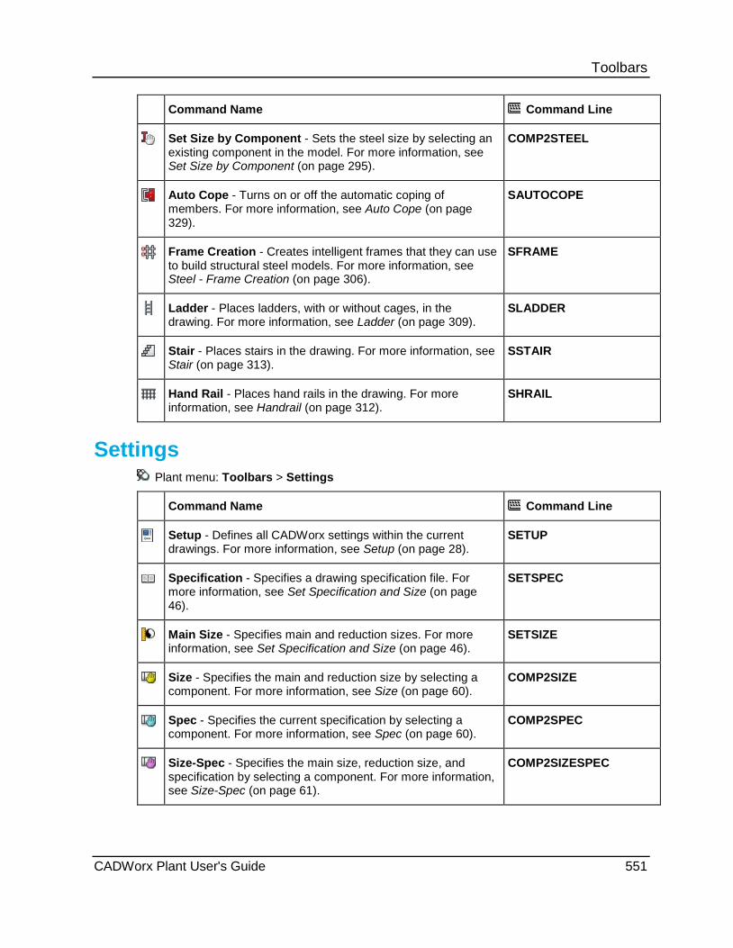
Toolbars Command Name Command Line
Set Size by Component - Sets the steel size by selecting an existing component in the model. For more information, see Set Size by Component (on page 295).
COMP2STEEL
Auto Cope - Turns on or off the automatic coping of members. For more information, see Auto Cope (on page 329).
SAUTOCOPE
Frame Creation - Creates intelligent frames that they can use to build structural steel models. For more information, see Steel - Frame Creation (on page 306).
SFRAME
Ladder - Places ladders, with or without cages, in the drawing. For more information, see Ladder (on page 309).
SLADDER
Stair - Places stairs in the drawing. For more information, see Stair (on page 313).
SSTAIR
Hand Rail - Places hand rails in the drawing. For more information, see Handrail (on page 312).
SHRAIL
Settings Plant menu: Toolbars > Settings
Command Name Command Line
Setup - Defines all CADWorx settings within the current drawings. For more information, see Setup (on page 28).
SETUP
Specification - Specifies a drawing specification file. For more information, see Set Specification and Size (on page 46).
SETSPEC
Main Size - Specifies main and reduction sizes. For more information, see Set Specification and Size (on page 46).
SETSIZE
Size - Specifies the main and reduction size by selecting a component. For more information, see Size (on page 60).
COMP2SIZE
Spec - Specifies the current specification by selecting a component. For more information, see Spec (on page 60).
COMP2SPEC
Size-Spec - Specifies the main size, reduction size, and specification by selecting a component. For more information, see Size-Spec (on page 61).
COMP2SIZESPEC
CADWorx Plant User's Guide 551
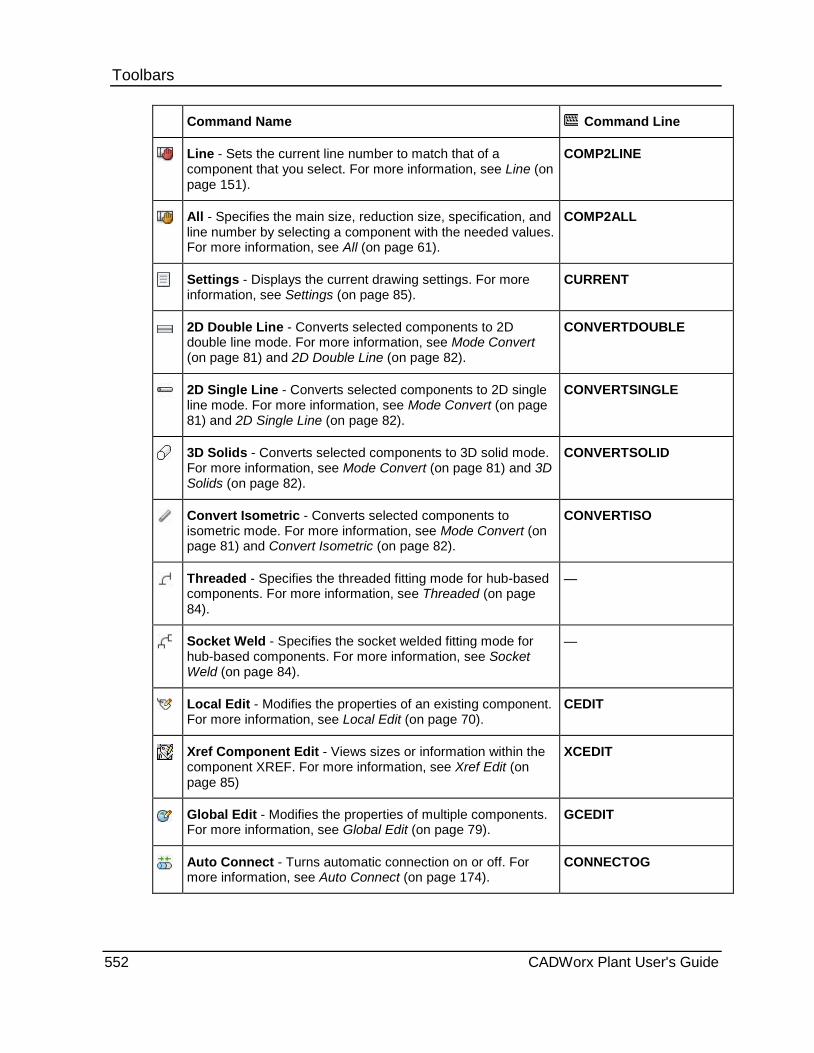
Toolbars Command Name Command Line
Line - Sets the current line number to match that of a component that you select. For more information, see Line (on page 151).
COMP2LINE
All - Specifies the main size, reduction size, specification, and line number by selecting a component with the needed values. For more information, see All (on page 61).
COMP2ALL
Settings - Displays the current drawing settings. For more information, see Settings (on page 85).
CURRENT
2D Double Line - Converts selected components to 2D double line mode. For more information, see Mode Convert (on page 81) and 2D Double Line (on page 82).
CONVERTDOUBLE
2D Single Line - Converts selected components to 2D single line mode. For more information, see Mode Convert (on page 81) and 2D Single Line (on page 82).
CONVERTSINGLE
3D Solids - Converts selected components to 3D solid mode. For more information, see Mode Convert (on page 81) and 3D Solids (on page 82).
CONVERTSOLID
Convert Isometric - Converts selected components to isometric mode. For more information, see Mode Convert (on page 81) and Convert Isometric (on page 82).
CONVERTISO
Threaded - Specifies the threaded fitting mode for hub-based components. For more information, see Threaded (on page 84).
—
Socket Weld - Specifies the socket welded fitting mode for hub-based components. For more information, see Socket Weld (on page 84).
—
Local Edit - Modifies the properties of an existing component. For more information, see Local Edit (on page 70).
CEDIT
Xref Component Edit - Views sizes or information within the component XREF. For more information, see Xref Edit (on page 85)
XCEDIT
Global Edit - Modifies the properties of multiple components. For more information, see Global Edit (on page 79).
GCEDIT
Auto Connect - Turns automatic connection on or off. For more information, see Auto Connect (on page 174).
CONNECTOG
552 CADWorx Plant User's Guide

Toolbars Command Name Command Line
Zoom Lock - Allows zooming in paper space only. For more information, see Zoom Lock (on page 214).
ZOOMLOCK
Optional Items - Places a component when the component type in the specification has an optional component. For more information, see Optional Items (on page 59).
SPECOPTION
Group On/Off - Turns on or off the grouping of the centerline of the component with the accompanying graphics. For more information, see Group On/Off (on page 175).
GROUPTOG
Selection Control - Toggles the display of grips on and off. For more information, Select Control (on page 329).
SELECTCONTROL
Defines all CADWorx settings within the current drawings
Palettes Plant menu: Toolbars > Misc
Command Name Command Line
Spec View - Filters the available components based on the size and specification settings. For more information, see Spec View Palette (on page 88).
SPECVIEW
Line View -Isolates components based on their line number or their specification. For more information, see Line View Palette (on page 91).
LINEVIEW
Insulation View - Creates a data file in which you can add, modify and remove insulation configurations that can be applied to CADWorx components. For more information, see Insulation View Palette (on page 100).
INSULATIONVIEW
Clash View - Runs interactive clash detection on AutoCAD 3D solids in the current drawing as well as any attached XREF drawings. For more information, see Clash View Palette (on page 111).
CLASHVIEW
Pipe Support Modeler Report - Generates a report of all pipe supports found in the selection or in the entire model. For more information, see Pipe Support Report (on page 106).
PIPESUPPORTREPORT
Discontinuity View - Checks for different types of modeling issues. For more information, see Discontinuity View Palette (on page 104).
DISCONTINUITYVIEW
P&ID View - Links data between the Plant and P&ID table in a project database. For more information, see P&ID View Palette (on page 107).
PIDVIEW
CADWorx Plant User's Guide 553

Toolbars
554 CADWorx Plant User's Guide

A P P E N D I X A
CADWorx Plant specification files (.prj) are delivered in the [Product Folder]\Plant\Spec folder.
You can relocate these files to other local or network folders:
Change the location of the Spec folder by modifying the SpecificationDirectory (on page 42) variable stored in the current configuration settings.
Editing Component Data Files CADWorx Plant uses a component data text file to determine the correct dimensions of components. When you select a component, the software checks the current specification, retrieves data from the correct data file, and draws the component.
Use the Spec Editor to create new data files for components and the needed component sizes. The data file structure that is required for each component is provided in the DataFile.tbl file in the [Product Folder]\Plant\System folder. This file is used to generate template data. For more information, see the Spec Editor documentation delivered with CADWorx.
Specification and Data Files
CADWorx Plant User's Guide 555
Specification and Data Files
556 CADWorx Plant User's Guide

A P P E N D I X B
In This Appendix Modifying a User Profile ................................................................ 557 Creating a Base Profile .................................................................. 558 Running CADWorx Equipment or PV Fabricator with CADWorx Plant 558 Special Monitored Commands Used With a Live Database ......... 560
Modifying a User Profile You can run CADWorx Plant from any network or local folder by manually creating or modifying a user profile and modifying the search paths in the profile.
CADWorx runs within AutoCAD by using the AutoCAD user profile command line switch, /P. A user profile shortcut is created when Plant is installed. For example, if AutoCAD is installed in the C:\Program Files\Autodesk\AutoCAD folder, a shortcut is created for CADWorx Plant. The value of Target on the Shortcut tab of the Properties dialog box for the shortcut is:
"C:\Program Files\Autodesk\AutoCAD\acad.exe" /P "Profile Name"
Manually create a profile by modifying the support file search paths and the template file location.
1. In Plant, click Tools > Options.
The Options dialog box appears.
2. On the Files tab, expand Support File Search Path in the Search paths, file names, and file locations list.
The [Product Folder]\Plant\Support folder is listed first, as shown in the example below.
The acad.rx file is in the support folder. AutoCAD uses acad.rx to load the Plant menus, toolbars, and panels.
3. Select the folder name and type the new folder path.
4. Manually create the new support folder and copy the acad.rx file to this folder.
5. On the Files tab, expand Template Settings > Drawing Template File Location.
AutoCAD Workflows Used With Plant
CADWorx Plant User's Guide 557
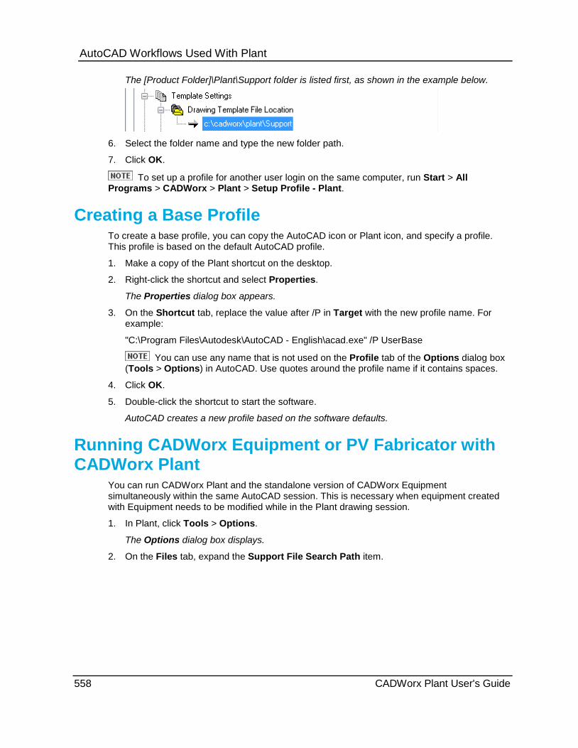
AutoCAD Workflows Used With Plant
The [Product Folder]\Plant\Support folder is listed first, as shown in the example below.
6. Select the folder name and type the new folder path.
7. Click OK.
To set up a profile for another user login on the same computer, run Start > All Programs > CADWorx > Plant > Setup Profile - Plant.
Creating a Base Profile To create a base profile, you can copy the AutoCAD icon or Plant icon, and specify a profile. This profile is based on the default AutoCAD profile.
1. Make a copy of the Plant shortcut on the desktop.
2. Right-click the shortcut and select Properties.
The Properties dialog box appears.
3. On the Shortcut tab, replace the value after /P in Target with the new profile name. For example:
"C:\Program Files\Autodesk\AutoCAD - English\acad.exe" /P UserBase
You can use any name that is not used on the Profile tab of the Options dialog box (Tools > Options) in AutoCAD. Use quotes around the profile name if it contains spaces.
4. Click OK.
5. Double-click the shortcut to start the software.
AutoCAD creates a new profile based on the software defaults.
Running CADWorx Equipment or PV Fabricator with CADWorx Plant
You can run CADWorx Plant and the standalone version of CADWorx Equipment simultaneously within the same AutoCAD session. This is necessary when equipment created with Equipment needs to be modified while in the Plant drawing session.
1. In Plant, click Tools > Options.
The Options dialog box displays.
2. On the Files tab, expand the Support File Search Path item.
558 CADWorx Plant User's Guide
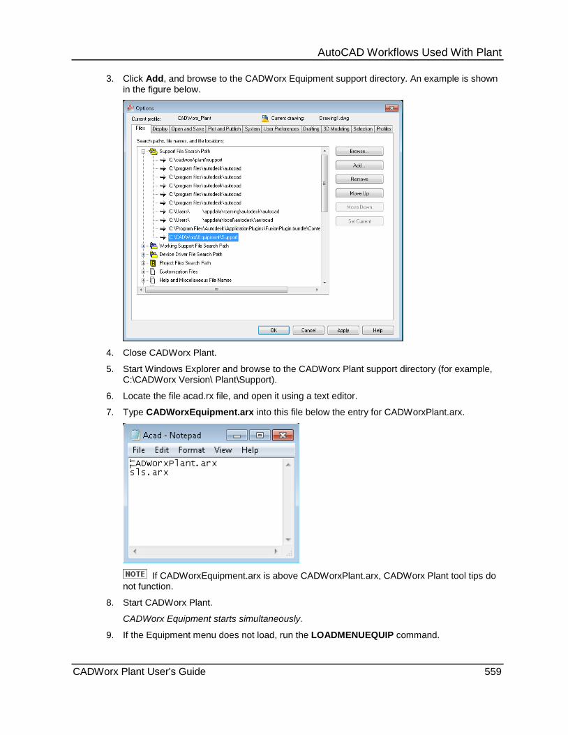
AutoCAD Workflows Used With Plant 3. Click Add, and browse to the CADWorx Equipment support directory. An example is shown
in the figure below.
4. Close CADWorx Plant.
5. Start Windows Explorer and browse to the CADWorx Plant support directory (for example, C:\CADWorx Version\ Plant\Support).
6. Locate the file acad.rx file, and open it using a text editor.
7. Type CADWorxEquipment.arx into this file below the entry for CADWorxPlant.arx.
If CADWorxEquipment.arx is above CADWorxPlant.arx, CADWorx Plant tool tips do
not function.
8. Start CADWorx Plant.
CADWorx Equipment starts simultaneously.
9. If the Equipment menu does not load, run the LOADMENUEQUIP command.
CADWorx Plant User's Guide 559
AutoCAD Workflows Used With Plant
Special Monitored Commands Used With a Live Database
This following AutoCAD commands are monitored by CADWorx for live external database synchronization. When any of the commands are used, CADWorx automatically updates a live external database.
Erase and Undo Commands These commands remove and restore graphic entities and mark rows in the database. If a CADWorx component is deleted from the drawing, the row from the database is deleted when the drawing file is closed.
ERASE U UNDO REDO MREDO OOPS BLOCK -WBLOCK EXPLODE CUTCLIP GROUP
Copy Commands These commands add new graphic entities to the model.
COPY BREAK ARRAY GRIP_COPY GRIP_MIRROR EXPLODE MIRROR PASTECLIP PASTEORIG DROPGEOM
Move Commands These commands move the graphic entities in the model.
MOVE GRIP_STRETCH STRETCH DROPGEOM
560 CADWorx Plant User's Guide

A P P E N D I X C
Items added and updated with CADWorx Plant Professional 2014 SP1
Software Enhancements You can view ISOGEN continuation graphics by setting the
ISOGENContinuationGraphicsCount variable. For more information, see ISOGENContinuationGraphicsCount (on page 38).
Updated the Nozzle Generic Attach command to improve the overall application of the option. For more information, see Nozzle Generic Attach (on page 200).
You can now use alpha characters in the spool, mark, and sheet number in the ISOGEN Data dialog box. For more information, see ISOGEN Data Dialog Box (on page 73).
You can now turn off updates for Custom Data, and Line Number in the Apply Change Data Rule. For more information, see Apply Change Data Rule Dialog Box (on page 54).
SP1 Improvements Improved the Change Specification command to provide you a list of components in the
case of multiple matching components. For more information, see Change Specification (on page 68).
Items added and updated with CADWorx Plant Professional 2014
Software Enhancements Updated the Pipe Support Palette to reflect the new Specification Editor Pipe Support
changes and the use of dynamic pipe supports. This option also enables new pipe supports on tees. For more information, see Support Modeler Palette (on page 94).
Tees can now be converted to crosses after routing by using the grip point on the main of the tee.
Reducers can now have branches routed from the side with the added grip point.
Multiple components can now move simultaneously by using the MOVECOMPONENT command. For more information, see Continue Routing (on page 223).
Tubing can now be stretched only by using the square grip point at the end point of the tube run. Also pipe can be routed from an existing tube. For more information, see Tube (on page 498).
Center of Gravity has now been updated. All center of gravity calculations can be completed within a single dialog box. For more information, see C.G. Generator (on page 171).
Generic Attach has been updated to include the BOM Mark Point and the CG Location, enabling you to select a point for the Center of Gravity. For more information, see Generic Attach (on page 202) and Steel - Generic Attachment (on page 295).
Update History
CADWorx Plant User's Guide 561
Update History OrthoGen capability has been added to CADWorx. For more information, see OrthoGen
Panel (on page 143).
Gaskets, Bolts, and Welds have been enhanced for appearance. They now appear as they would in a real world environment when in enhanced mode.
There have been ISOGEN identifiers added to the ISOGEN Export Options for user shapes. For more information, see ISOGEN Export Options (on page 182).
You can now set a minimum spacing rule for the O-Lets. For more information, see Apply O-let Minimum Spacing Rule (on page 55).
You can now have custom data that is attached to components appear in the data. You can also isolate components based on this custom data. A Custom Data button has been added to the Component Edit dialog box and the Global CEdit dialog box. For more information, see Local Edit (on page 70), Global Edit (on page 79), Component Custom Data Dialog Box (on page 78) and Custom Data Dialog Box (on page 80).
You can now review changes you have made to a database when you synchronize by setting the SyncOnStartUp variable to Synchronize with Changes Review. For more information, see SyncOnStartUp (on page 44) and Synchronize Pipe Database (on page 169).
You can now set the Routing Mode in the CADWorx Plant Setup. For more information, Setup (on page 28).
You can now isolate the reverse of the selected items in the CADWorx Line View palette. You can also manage your isolation in the Line View Isolation Properties Manager added to the CADWorx Line View palette. You can set the file created in the Line View Isolation Properties Manager to a default by setting it in the LineViewIsolationSettingsFile variable. This also allows you to isolate based on custom data. For more information, see Line View Palette (on page 91), Line Isolate Tab (CADWorx Line View Palette) (on page 92), Line View Isolation Properties Manager (on page 93), and LineViewIsolationSettingsFile (on page 41).
You can now break pipes into segments and change segmented pipe to non-segmented pipe. For more information, see Join Pipe (on page 175) and Break Pipe (on page 200).
You can now change the elevation of placed piping in the drawing. For more information, see Change Elevation (on page 207).
You can now generic attach for nozzles using the ENGENERIC command. For more information, see Nozzle Generic Attach (on page 200).
You can now enable the RepeatFile in ISOGEN which enables start and split locations for consecutive ISOGEN outputs. Set the ISOGENSetting variable to control the import of the repeat file data. The number of sheets is then added to the ISOGEN Data dialog box. For more information, see ISOGENSetting (on page 38) and ISOGEN Out (on page 118).
Intersecting piping components can now be converted. Options are presented to you when a piping component crosses another component. If you selected None from the list, you can use the CONVERTINTERSECTEDPIPINGS command to convert the intersecting piping. For more information, see Convert Intersected Piping (on page 84).
562 CADWorx Plant User's Guide
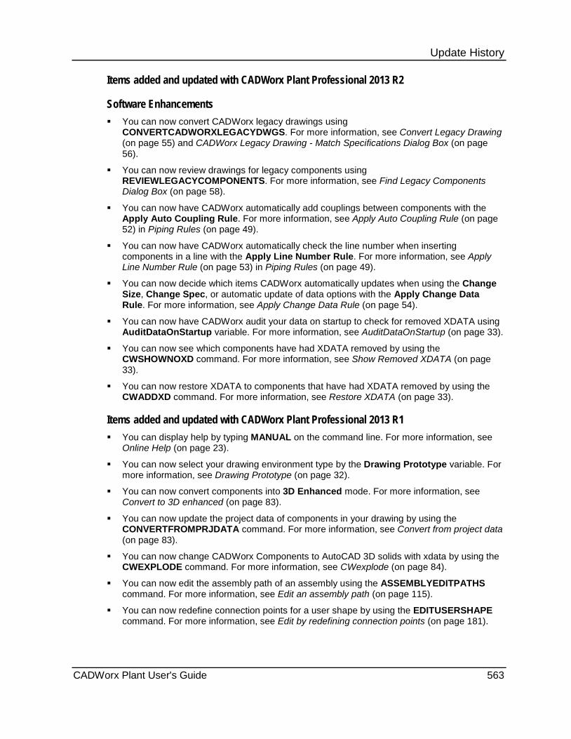
Update History Items added and updated with CADWorx Plant Professional 2013 R2
Software Enhancements You can now convert CADWorx legacy drawings using
CONVERTCADWORXLEGACYDWGS. For more information, see Convert Legacy Drawing (on page 55) and CADWorx Legacy Drawing - Match Specifications Dialog Box (on page 56).
You can now review drawings for legacy components using REVIEWLEGACYCOMPONENTS. For more information, see Find Legacy Components Dialog Box (on page 58).
You can now have CADWorx automatically add couplings between components with the Apply Auto Coupling Rule. For more information, see Apply Auto Coupling Rule (on page 52) in Piping Rules (on page 49).
You can now have CADWorx automatically check the line number when inserting components in a line with the Apply Line Number Rule. For more information, see Apply Line Number Rule (on page 53) in Piping Rules (on page 49).
You can now decide which items CADWorx automatically updates when using the Change Size, Change Spec, or automatic update of data options with the Apply Change Data Rule. For more information, see Apply Change Data Rule (on page 54).
You can now have CADWorx audit your data on startup to check for removed XDATA using AuditDataOnStartup variable. For more information, see AuditDataOnStartup (on page 33).
You can now see which components have had XDATA removed by using the CWSHOWNOXD command. For more information, see Show Removed XDATA (on page 33).
You can now restore XDATA to components that have had XDATA removed by using the CWADDXD command. For more information, see Restore XDATA (on page 33).
Items added and updated with CADWorx Plant Professional 2013 R1 You can display help by typing MANUAL on the command line. For more information, see
Online Help (on page 23).
You can now select your drawing environment type by the Drawing Prototype variable. For more information, see Drawing Prototype (on page 32).
You can now convert components into 3D Enhanced mode. For more information, see Convert to 3D enhanced (on page 83).
You can now update the project data of components in your drawing by using the CONVERTFROMPRJDATA command. For more information, see Convert from project data (on page 83).
You can now change CADWorx Components to AutoCAD 3D solids with xdata by using the CWEXPLODE command. For more information, see CWexplode (on page 84).
You can now edit the assembly path of an assembly using the ASSEMBLYEDITPATHS command. For more information, see Edit an assembly path (on page 115).
You can now redefine connection points for a user shape by using the EDITUSERSHAPE command. For more information, see Edit by redefining connection points (on page 181).
CADWorx Plant User's Guide 563
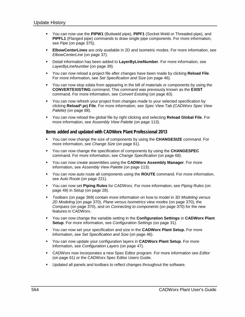
Update History You can now use the PIPW1 (Buttweld pipe), PIPF1 (Socket Weld or Threaded pipe), and
PIPFL1 (Flanged pipe) commands to draw single pipe components. For more information, see Pipe (on page 375).
ElbowCenterLines are only available in 2D and Isometric modes. For more information, see ElbowCenterLine (on page 37).
Detail information has been added to LayerByLineNumber. For more information, see LayerByLineNumber (on page 39).
You can now reload a project file after changes have been made by clicking Reload File. For more information, see Set Specification and Size (on page 46).
You can now stop xdata from appearing in the bill of materials or components by using the CONVERTEXISTING command. This command was previously known as the EXIST command. For more information, see Convert Existing (on page 83).
You can now refresh your project from changes made to your selected specification by clicking Reload*.prj File. For more information, see Spec View Tab (CADWorx Spec View Palette) (on page 88).
You can now reload the global file by right clicking and selecting Reload Global File. For more information, see Assembly View Palette (on page 113).
Items added and updated with CADWorx Plant Professional 2013 You can now change the size of components by using the CHANGESIZE command. For
more information, see Change Size (on page 61).
You can now change the specification of components by using the CHANGESPEC command. For more information, see Change Specification (on page 68).
You can now create assemblies using the CADWorx Assembly Manager. For more information, see Assembly View Palette (on page 113).
You can now auto route all components using the ROUTE command. For more information, see Auto Route (on page 221).
You can now set Piping Rules for CADWorx. For more information, see Piping Rules (on page 49) in Setup (on page 28).
Toolbars (on page 369) contain more information on how to model in 3D Modeling versus 2D Modeling (on page 370), Plane versus Isometrics view modes (on page 370), the Compass (on page 370), and on Connecting to components (on page 370) for the new features in CADWorx.
You can now change the variable setting in the Configuration Settings in CADWorx Plant Setup. For more information, see Configuration Settings (on page 31).
You can now set your specification and size in the CADWorx Plant Setup. For more information, see Set Specification and Size (on page 46).
You can now update your configuration layers in CADWorx Plant Setup. For more information, see Configuration Layers (on page 47).
CADWorx now incorporates a new Spec Editor program. For more information see Editor (on page 61) or the CADWorx Spec Editor Users Guide.
Updated all panels and toolbars to reflect changes throughout the software.
564 CADWorx Plant User's Guide
2 2D Double Line • 82 2D Panel • 211 2D Representation • 211 2D Representation Hidden • 212 2D Single Line • 82
3 3D Modeling versus 2D Modeling • 370 3D Solids • 82 3-Way Plan Valve • 423 3-Way Side Valve • 425 3-Way Vertical Valve • 426
4 45 LR Ell • 387 4-Way Plan Valve • 424 4-Way Side Valve • 426
9 90 LR Ell • 386 90 SR Ell • 387
A Accessing and Docking the Toolbars • 369 Add a user shape to a specification • 196 Add an HVAC shape to the drawing • 348 Add or remove properties from BOM • 155,
333, 358 Adjust a dimension to match a pipe • 209 Adjust a pipe length to match a dimension •
209 Adjustable Bend • 384 Aliases and Command Names • 370 All • 61 AlphaSizeControl • 32 Anchor • 262 Angle Double Shape • 285 Angle Shape with Lip • 283 Angle Shapes • 276 Angle Side Valve • 428 Angle Top Valve • 425 Annotate • 150 Annotate Component • 328 Apply Auto Coupling Rule • 52
Apply Bolt Hole Orientation Rule • 52 Apply Bolt Insertion Rule • 51 Apply Branch Table Rule • 51 Apply Change Data Rule • 54 Apply Change Data Rule Dialog Box • 54 Apply End Type Rule • 50 Apply Flange Insertion Rule • 51 Apply Gasket Insertion Rule • 51 Apply Line Number Rule • 53 Apply O-let Minimum Spacing Rule • 55 Apply Pipe End Prep Rule • 52 Apply Pipe Healing Rule • 51 Apply Pipe Length Rule • 50 Apply Size Rule • 49 Apply Skew Pipe Maximum Angle • 55 Apply Specification Rule • 50 Apply Tab (CADWorx Insulation View
Palette) • 102 Apply Trimmed Elbow Rule • 51 Apply Weld Insertion Rule • 50 Arrow • 246 Assembly View Palette • 113 Assign • 149 Assign line numbers • 150 Audit HVAC Database • 366 Audit Pipe Database • 168 Audit Steel Database • 342 Audit the HVAC database • 367 AuditDataOnStartup • 33 Auto Connect • 174 Auto Cope • 329 Auto Gasket • 215 Auto Route • 221 Auto Routing from the strainer lateral • 543 Auto Weld • 217 AutoCAD Workflows Used With Plant • 557 AutoDimensionBox • 33 Automatic • 216, 230
B Ball Valve • 417 Base Plate • 290 Bill of Material Setup • 154 Bleed Ring or Spacer • 544 Blind Flange • 406 Bolt • 215 BoltRoundControl • 35
Index
CADWorx Plant User's Guide 565

Index BOM Sort Order / Accumulation Dialog Box
• 157 BomBoltControl • 34 BomScheduleDirection • 34 BomScheduleSpacing • 34 BomTagGridFactor • 34 BomTagOptimize • 35 BomTagRadiusFactor • 35 BomTagSpacingFactor • 35 Box • 212 Break by Length • 200 Break by Number • 200 Break Pipe • 200 Butterfly Valve • 420 Buttweld • 371 Buttweld LR • 227 Buttweld SR • 227 Buttweld Valves • 415
C C.G. Generator • 171 CADWorx Legacy Drawing - Match
Specifications Dialog Box • 56 CADWorxMaterial • 35 CAESARIIMaterial • 36 CAESARIIMemory • 36 CAESARIITolerance • 36 CAESARIIVersion • 36 Cap • 381 Center Line • 55 Change • 233 Change Elevation • 207 Change elevation by BOP • 208 Change elevation by entering the elevation
value • 207 Change elevation by Pick • 208 Change elevation by TOP • 208 Change Layer • 256 Change position and direction of generic
nozzle • 202 Change Size • 61 Change Specification • 68 Change tee sizes automatically • 65 Change tee sizes manually • 66 Change text alignment in columns • 156,
333, 359 Change the BOM sorting and accumulation
• 156, 333, 359 Change the column order • 156, 333, 359 Change the Elevation • 233 Change the layer associated with an object
• 256
Change the layers associated with HVAC components • 365
Change the size automatically • 62 Change the size manually • 63 Change the size of a model with branch
connections automatically • 64 Change the size of a reducer and the pipes
automatically • 63 Change the size of a reducer and the pipes
manually • 64 Change the specification automatically • 68 Change the specification manually • 69 Change the specification of a model with
branches automatically • 70 Channel Shape with Lip • 282 Channel Shapes • 275 Check Valve • 419 Clash View Palette • 111 Compass • 268, 370 Component • 234 Component Custom Data Dialog Box • 78 Conc Reducer • 380 Configuration Layers • 47 Configuration Settings • 31 Connecting to components • 370 Continue Routing • 223 Control Valve • 422 Conventions • 17 Convert a component to a different mode •
82 Convert Existing • 83 Convert from project data • 83 Convert Intersected Piping • 84 Convert Isometric • 82 Convert Legacy Drawing • 55 Convert Solid • 328 Convert to 3D enhanced • 83 Coordinates • 235 Count • 148 Count weld gaps automatically • 219 Coupling • 441 Create a 2D representation • 212 Create a 2D representation with hidden
lines • 212 Create a 2D single line user shape • 194 Create a 2D user shape • 193 Create a 3D user shape • 191 Create a new frame configuration • 307 Create a user shape file • 180 Create a user shape from a block • 189 Create a user shape from a polyline • 188 Create a user shape from points • 186 Create an assembly • 114
566 CADWorx Plant User's Guide

Index Creating a Base Profile • 558 Cross Plan • 462 Cross Reducing Plan • 462 Cross Reducing Side • 478 Cross Reducing Vertical • 479 Cross Side • 478 Custom Data Dialog Box • 80 Custom Data Tab (CADWorx Spec View
Palette) • 91 Cut • 319 Cut BOM using Automatic placement • 158,
335, 361 Cut BOM using Manual placement • 159,
336, 361 Cut HVAC Bill of Material • 360 Cut members by line • 319 Cut members by three-point plane • 319 Cut Pipe Bill of Material • 157 Cut Steel Bill of Material • 334 CWexplode • 84
D Data Remove • 364 DataBaseCodesISOGEN • 36 DB Generate • 365 DB In • 366 Decrement • 149 Define a weld gap • 539 Delete a layer • 257 Delete an assembly from the Assembly
Manager • 115 Delete Bill of Material • 163 Delete Layer • 256 Detail • 242 Diaphragm Valve • 421 Dim Adjustment • 208 Dimension Panel • 229 DimensionsExcludedSlope • 37 DimensionsExistingISOGEN • 37 Discontinuity View Palette • 104 Display only the layer associated with an
object • 258 Dots • 250 Draw non-pipe components • 89 Draw pipe components • 89 Drawing Prototype • 32 Dual Check Valve • 422
E East • 270 Ecc Reducer • 380
Edit • 213, 320, 356 Edit a frame configuration • 308 Edit an assembly • 114 Edit an assembly path • 115 Edit an existing user shape • 181 Edit by redefining connection points • 181 Edit HVAC components globally • 357 Edit Pipe Support Features • 98 Editing Component Data Files • 555 Editor • 61 Elbow Centerline • 209 ElbowCenterLine • 37 Elbowlet Socket Weld in Plan • 509 Elbowlet Socket Weld in Side • 521 Elbowlet Socket Weld in Vertical • 521 Elbowlet Thread in Plan • 509 Elbowlet Thread in Side • 520 Elbowlet Thread in Vertical • 521 Elbowlet Weld in Plan • 508 Elbowlet Weld in Side • 519 Elbowlet Weld in Vertical • 520 Elevation • 234, 245 Enable curved piping in Plant isometrics •
122 Enable the Repeatability return report • 120 End Type Information • 140 Enter User Name and Password Dialog Box
• 165 Expansion Joint • 545 Export CADWorx HVAC data • 366 Export Pipe • 165 Export Pipe Bill of Material • 162 Export Steel • 341 Export Steel Bill of Material • 339 Export Steel Model • 343 Extract batch ISOGEN files • 123 Extract ISOGEN files • 120 Extract piping component files • 129
F Fiberglass • 434 Fiberglass Pipe • 437 Find Legacy Components Dialog Box • 58 Find Tab (CADWorx Line View Palette) • 93 FittingWidth • 37 Flange O.D. • 253 Flanged 45 Degree Elbow Plan • 443 Flanged 45 Degree Elbow Side • 450 Flanged 45 Degree Elbow Vert • 450 Flanged 90 Degree Elbow Plan • 442 Flanged 90 Degree Elbow Side • 449 Flanged Concentric Reducer • 444
CADWorx Plant User's Guide 567

Index Flanged Plan • 543 Flanged Side • 546 Flanged Tee Plan • 444 Flanged Tee Side • 451 Flanged Tee Vertical • 451 Flanges • 402 Flat • 267 Flat Bar Shapes • 280 Flgd/BW Valves • 415 Frame Annotation • 308 Full Coupling End • 448
G Gasket • 538 Gaskets, Etc. • 538 Gate Valve • 417 GC Edit • 356 Generate a CAESAR II input file • 198 Generic Attach • 202, 354 Global Edit • 79, 325 Global Edit All • 325 Globe Valve • 418 Graphics / Pipe Ends • 237 Group On/Off • 175 Guide • 264
H Handrail • 312 Height • 236 Hidden End • 253 Horizontal • 230 Horizontal with Tail • 232 HVAC • 346 HVAC BOM Setup • 357 HVAC Draw / BOM / DB Panel • 345 HVAC Shapes Catalog • 348 HVACLibraryDirectory • 37
I Import CADWorx HVAC data • 366 Import Pipe • 168 Import Pipe Bill of Material • 163 Import Steel • 342 Import Steel Model • 344 Increment • 149 Insert a drawing into the project • 110 Insert a flange O.D. • 253 Insert a gasket • 539 Insert a hidden end • 254 Insert a pipe end • 254 Insert a pipe support • 96
Insert a plain end • 253 Insert a reinforcement pad • 260 Insert a reinforcement saddle • 261 Insert a tee support • 97 Insert an assembly into the drawing • 115 Insert an elbow support • 96 Insert multiple pipe supports • 97 Insert Tag • 164 Instrument • 244 Insulation View Palette • 100 ISO • 248 ISO Flag • 210 ISO Text • 236 ISOGEN Batch • 123 ISOGEN Data Dialog Box • 73 ISOGEN Export Options • 182 ISOGEN Information • 130 ISOGEN Out • 118 ISOGEN Panel • 117 ISOGEN Project Manager / I-Configure •
130 ISOGEN Start Point • 125 ISOGEN Supplemental • 123 ISOGENContinuationGraphicsCount • 38 ISOGENDefaultStyle • 38 ISOGENSetting • 38 Isolate Layer • 258
J Join by Run • 176 Join by Segment • 176 Join Pipe • 175
L Label components with line numbers • 150 Ladder • 309 LanguageFile • 38 Lap Joint Flange • 409 Lateral Plan • 463 Lateral Side • 479 Lateral Vertical • 480 Latrolet Socket Weld in Plan • 510 Latrolet Socket Weld in Side • 523 Latrolet Thread in Plan • 510 Latrolet Thread in Side • 522 Latrolet Weld in Plan • 509 Latrolet Weld in Side • 522 Layer Change • 328, 364 Layer Off • 257 Layer On • 257 LayerByLineNumber • 39
568 CADWorx Plant User's Guide

Index Layers Dialog Box • 113 Layers Panel • 255 Line • 151 Line Isolate • 151 Line Isolate Tab (CADWorx Line View
Palette) • 92 Line Numbering System Dialog Box • 146 Line Numbering System Dropdown Setup
Dialog Box • 90 Line Numbers • 548 Line View Isolation Properties Manager • 93 Line View Palette • 91 Lined • 428 Lined Eccentric Reducer • 431 Lined Pipe • 431 Lined Wye Plan • 432 Lined Wye Side • 433 Lined Wye Vert • 433 LineNumberSystem • 41 LineViewIsolationSettingsFile • 41 Link components • 109 LNum Panel • 145 Local Edit • 70 Loft • 299 Long Weld Neck • 410
M Match an object's layer • 257 Match Layer • 257 Matched Tab (CADWorx P&ID View
Palette) • 107 Material List Definition • 130 Misc • 251, 541 Misc Panel • 173 Miter • 318 Miters • 383 Mode Convert • 81 Modeling in 2D • 390, 425, 433, 445, 474,
511, 535, 546 Modeling in 3D • 375, 417, 431, 437, 459,
496, 526, 543 Modify a component • 72 Modify a user-defined HVAC shape • 354 Modify an HVAC shape • 348 Modify an HVAC shape from the catalog •
351 Modify multiple components • 80 Modifying a User Profile • 557 Moveline • 225 MVSetup • 25
N Nipolet Thread in Plan • 511 Nipolet Thread in Vertical • 523 Nipolet Weld in Plan • 510 Nipolet Weld in Vertical • 523 Nipple • 497 Non Standard • 219 North • 268 Nozzle Generic Attach • 200
O Obsolete Commands • 22 Offset Tap • 125 Online Help • 23 Operators • 548 Optional Component Dialog Box • 59 Optional Items • 59 Options Dialog Box • 112 OrthoGen Launch • 143 OrthoGen Out • 143 OrthoGen Panel • 143
P P&ID View Palette • 107 Palettes • 553 Palettes Panel • 87 PCF In • 129 PCF Out • 128 Pipe • 375 Pipe BOM / DB Panel • 153 Pipe End • 254 Pipe Ends • 540 Pipe Shapes • 278 Pipe Support Report • 106 PipeDescriptionCat • 41 PipeSupportSetting • 42 Piping Rules • 49 Place a 180 degree plan return • 379 Place a 180 degree side return • 395, 396 Place a 180 degree vertical return • 395,
396 Place a 3-way plan valve • 423, 472, 532 Place a 3-way side valve • 426, 485, 536 Place a 3-way vertical valve • 426, 486, 536 Place a 45 degree rolled elbow • 388 Place a 4-way plan valve • 424, 532 Place a 4-way side valve • 426, 536 Place a 90 degree plan elbow • 376, 438,
443, 459, 499 Place a 90 degree reducing plan elbow •
377, 460, 501
CADWorx Plant User's Guide 569
Index Place a 90 degree rolled elbow • 386, 387 Place a 90 degree side street elbow • 512 Place a 90 degree street plan elbow • 500 Place a base plate • 292 Place a base plate with holes • 292 Place a bleed ring • 544 Place a bushing • 442, 506 Place a cap • 381, 442, 468, 504 Place a concentric reducer • 380, 439, 444,
466, 503 Place a concentric reducer swage • 502 Place a coupling • 441, 467, 468, 506, 507 Place a coupling end • 448, 517, 518 Place a detail graphic • 242 Place a fiberglass pipe • 437 Place a flange • 406, 409 Place a flange on a pipe • 403, 405, 407,
408, 411, 412, 414 Place a flange that mates with another
flange • 404, 405, 407, 408, 411, 413, 414
Place a frame in the drawing • 308 Place a gasket automatically • 216 Place a gasket manually • 216 Place a generic attachment in the drawing •
204, 355 Place a guide • 264 Place a ladder interactively • 311 Place a ladder using key-ins • 311 Place a ladder with a cage • 311 Place a miscellaneous graphic • 252 Place a mitered pipe • 383 Place a multi-port valve • 473, 474 Place a nipple • 497 Place a nonsymmetrical user shape in the
drawing • 197 Place a nozzle generic attachment • 201 Place a pipe • 375, 431 Place a plan cross • 381, 440, 462, 505 Place a plan elbow • 377, 389, 438, 443,
460, 464, 465, 500 Place a plan elbowlet fitting • 508, 509 Place a plan fitting • 507, 508, 510, 511 Place a plan flange pipe • 543 Place a plan flanged tee • 444 Place a plan graphic • 243 Place a plan lateral • 382, 441, 463, 464,
505 Place a plan latrolet fitting • 509, 510 Place a plan reducing cross • 382 Place a plan sock-o-let • 442 Place a plan tee • 378, 439, 461, 501, 502 Place a plan wye • 390, 432, 468
Place a plug • 506 Place a relief side valve • 533 Place a relief top valve • 537 Place a rigid element • 546 Place a rolled pipe • 384 Place a rolled tee • 388 Place a rotational restraint • 263 Place a sanitary plan reducing cross • 463 Place a sanitary side or vertical u-bend •
483, 484 Place a sanitary side reducing cross • 479 Place a sanitary u-bend • 466 Place a section graphic • 241 Place a side blind spectacle • 545 Place a side cross • 397, 447, 478, 516 Place a side elbowlet fitting • 520, 521 Place a side flange pipe • 546 Place a side flanged tee • 451 Place a side lateral • 398, 448, 479, 480,
516 Place a side latrolet fitting • 522, 523 Place a side or vertical elbow • 390, 391,
392, 399, 400, 445, 446, 449, 450, 474, 475, 476, 481, 482, 483, 512, 513
Place a side reducing cross • 397 Place a side reducing elbow • 392, 475, 514 Place a side socket weld threaded pipe •
544 Place a side socket weld/threaded pipe •
547 Place a side tee • 393, 394, 446, 476, 477,
514, 515 Place a side wye • 401, 433, 484 Place a snubber • 263 Place a spring hanger • 262 Place a stub or weld neck • 410 Place a symmetrical user shape in the
drawing • 197 Place a tap • 130 Place a threaded/socket pipe • 497 Place a translational restraint • 261 Place a user-defined HVAC shape • 354 Place a valve • 417, 418, 419, 420, 421,
422, 423, 469, 470, 471, 527, 528, 529, 530, 531, 534, 535
Place a vertical blind spectacle • 547 Place a vertical elbowlet fitting • 520, 521,
522 Place a vertical fitting • 518, 519, 523, 524 Place a vertical lateral • 398, 448, 480, 481,
517 Place a vertical reducing cross • 398, 479 Place a vertical soc-o-let • 449
570 CADWorx Plant User's Guide

Index Place a vertical strainer • 451 Place a vertical tee • 393, 394, 447, 477,
478, 515, 516 Place a vertical wye • 401, 433, 485 Place a weld dot graphic • 251 Place a weld symbol graphic • 248 Place an adjustable bend • 385 Place an anchor • 262 Place an angle side valve • 427, 428, 486,
537 Place an angle top valve • 533 Place an angle valve • 424, 425, 472 Place an arrow head graphic • 246 Place an eccentric reducer • 380, 432, 440,
467, 504 Place an eccentric reducer swage • 503 Place an elevation graphic • 245 Place an expansion joint • 545 Place an HVAC shape from the catalog •
351 Place an instrument graphic • 244 Place an isometric symbol graphic • 250 Place an offset tap • 128 Place automatic dimensions • 230 Place component annotation • 234 Place component elevation annotation • 235 Place coordinates • 235 Place hand rail by points • 313 Place hand rail by polyline • 313 Place horizontal dimensions • 230 Place horizontal tailed dimensions • 232 Place nonstandard stud bolts • 220 Place plate by closed polyline • 289 Place plate by curves • 290 Place plate by points • 289 Place rotated dimensions • 232 Place standard stud bolts • 219 Place stud bolts automatically • 216 Place stud bolts manually • 217 Place tick marks • 236 Place tubing • 498 Place vertical dimensions • 231 Place vertical tailed dimensions • 233 Place weld gaps automatically • 217 Place weld gaps manually • 218 Plain End • 253 Plan • 243 Plan 11.25 Ell • 388 Plan 180 LR Return • 379 Plan 180 SR Return • 379 Plan 22.5 Ell • 389 Plan 45 Ell • 377 Plan 90 LR Ell • 375
Plan 90 Reducing Ell • 377 Plan 90 SR Ell • 376 Plan Cross • 381 Plan Lateral • 382 Plan Reducing Cross • 382 Plan Reducing Tee • 378 Plan Tee • 378 Plan Threaded/Socket 90 Degree Elbow •
437 Plan Wye • 389 Plane versus Isometrics view modes • 370 Plate • 288 Plug Valve • 419 Point and Shoot UCS • 265 Preface • 17 Pressure Top Valve • 427 Previous • 258
R Read a CAESAR II input file • 207 Re-associate the Components • 210 Redisplay a layer turned off by the Layer
Off command • 257 Reducing Slip-on Flange • 410 Reducing Tee Plan • 461 Reducing Tee Side • 477 Reducing Tee Vertical • 478 Reducing Threaded Flange • 412 Reducing Weld Neck Flange • 413 Reinforcing Pad • 260 Reinforcing Saddle • 260, 545 Relief Side Valve • 424 Relief Top Valve • 427 Remove CADWorx data from components •
364 Restore XDATA • 33 Restraints • 540 Restraints Panel • 259 Rigid Element • 546 Rolled Pipe • 383 Rotary Valve • 421 Rotated • 232 Rotational • 263 Round Bar Shapes • 281 Route from a generic nozzle • 202 Route skewed pipe • 224 Router • 225 Router commands • 226 RT Panel • 221 Running CADWorx Equipment or PV
Fabricator with CADWorx Plant • 558
CADWorx Plant User's Guide 571
Index S Saddle in Vertical • 449 Sanitary • 452 Sanitary 11.25 Ell Plan • 465 Sanitary 11.25 Ell Side • 482 Sanitary 11.25 Ell Vertical • 483 Sanitary 22.5 Ell Plan • 464 Sanitary 22.5 Ell Side • 481 Sanitary 22.5 Ell Vertical • 482 Sanitary 3-Way Valve Plan • 472 Sanitary 3-Way Valve Side • 485 Sanitary 3-Way Valve Vertical • 485 Sanitary 45 Ell Plan • 460 Sanitary 45 Ell Side • 475 Sanitary 45 Ell Vertical • 476 Sanitary 90 Ell Plan • 459 Sanitary 90 Ell Side • 474 Sanitary 90 Reducing Ell Plan • 460 Sanitary 90 Reducing Ell Side • 475 Sanitary Angle Valve Plan • 472 Sanitary Angle Valve Side • 486 Sanitary Ball Valve • 469 Sanitary Butterfly Valve • 471 Sanitary Cap • 468 Sanitary Check Valve • 471 Sanitary Concentric • 466 Sanitary Eccentric • 466 Sanitary Gate Valve • 469 Sanitary Globe Valve • 470 Sanitary Lateral Reducing Plan • 463 Sanitary Lateral Reducing Side • 480 Sanitary Lateral Reducing Vertical • 481 Sanitary Multi 1 Port Valve • 473 Sanitary Multi 2 Port Valve • 473 Sanitary Multi 3 Port Valve • 473 Sanitary Nut/Coupling • 468 Sanitary Plug Valve • 470 Sanitary Stub • 467 Sanitary Tee Plan • 461 Sanitary Tee Side • 476 Sanitary Tee Vertical • 477 Sanitary U-Bend Plan • 465 Sanitary U-Bend Side • 483 Sanitary U-Bend Vertical • 484 Sanitary Wye Plan • 467 Sanitary Wye Side • 484 Sanitary Wye Vertical • 485 SaveLastProfileUsed • 42 Section • 240 Select Control • 329 Select Item Dialog Box • 166 Set • 147, 231
Set Layer • 256 Set line numbers based on a component •
148 Set line numbers based on a P&ID project •
148 Set line numbers based on the current
drawing • 148 Set Size by Component • 295 Set Specification & Size Dialog Box • 47 Set Specification and Size • 46 Set the active layer • 256 Set the current line number to that of a
component • 151 Set the Elevation • 231 Set the line count value • 149 Settings • 85, 551 Settings Tab (CADWorx Insulation View
Palette) • 101 Settings Tab (CADWorx Spec View Palette)
• 90 Setup • 25, 28, 146 Setup Live Database • 164 Setup Live Database Steel • 340 Setup short description column for material
list with text wrapping • 121 Setup Size/Spec Panel • 27 Shapes • 271 Show Removed XDATA • 33 Side 11.25 Ell • 399 Side 180 LR Return • 395 Side 180 SR Return • 396 Side 22.5 Ell • 400 Side 45 Ell • 391 Side 90 LR Ell • 390 Side 90 Reducing Ell • 392 Side 90 SR Ell • 391 Side Cross • 397 Side Lateral • 398 Side Reducing Cross • 397 Side Reducing Tee • 394 Side Tee • 393 Side Threaded/Socket 90 Degree Elbow •
445 Side Wye • 401 Single BOM using Automatic placement •
161, 339, 364 Single BOM using Manual placement • 162,
339, 364 Single HVAC Bill of Material • 363 Single Line Steel • 300 Single Pipe Bill of Material • 160 Single Steel Bill of Material • 338 SingleLineWidth • 42
572 CADWorx Plant User's Guide
Index Size • 60 Size-Spec • 61 SKEY Information • 131 Slip-on Flange • 404 Snubber • 263 Socket Type Flange • 406 Socket Weld • 84, 228 Sock-O-Let • 442 Sockolet Socket Weld in Plan • 508 Sockolet Socket Weld in Vertical • 519 South • 269 Spec • 60 Spec Editor • 89 Spec View Palette • 88 Spec View Tab (CADWorx Spec View
Palette) • 88 Special Monitored Commands Used With a
Live Database • 560 Specification and Data Files • 555 Specification and Size • 59 SpecificationDefaultProject • 43 SpecificationDirectory • 42 Specify the Bill of Material Mark Point and
the Center of Gravity Location • 205 Specify the weld dot size for a single line
pipe • 175 SpecSizeOverride • 43 Spectacle Blind Side • 545 Spectacle Blind Vertical • 547 Spring Hanger • 262 Stair • 313 Standard • 219 Start a new route • 223 Startup Defaults • 25 Startup Variables • 31 Steel • 549 Steel - Cope • 318 Steel - Frame Creation • 306 Steel - Generic Attachment • 295 Steel Bolts • 292 Steel BOM / DB Panel • 331 Steel BOM Setup • 332 Steel BOM Sort Order / Accumulation
Dialog Box • 334 Steel Draw Panel • 287 Steel Edit Panel • 317 Steel Shapes Panel • 271 SteelCopeBoltDistance • 43 SteelCopeWeldDistance • 43 SteelLibraryDirectory • 43 SteelNeutralAxis • 43 SteelPartNumberFile • 44 SteelRoundControl • 44
SteelRoundUnit • 44 SteelToolTipSetting • 44 Stop Sign • 124 Stub End • 409 Support Directory • 25 Support Modeler Palette • 94 SW/Thrd Plan • 544 SW/Thrd Side • 547 Synchronize HVAC Database • 367 Synchronize Pipe Database • 169 Synchronize Steel Database • 343 Synchronize the HVAC database • 367 SyncOnStartUp • 44 System In • 206 System Out • 198 System Prompts • 239 System Visibility • 210 SystemMeasure • 45
T Tag Location • 163 Tag Toggle Bill of Material • 163 Tap • 129 Technical Support • 18 Tee • 388 Tee Shapes • 277 TemplateDatabaseFile • 45 Thrd/SW 3 Way Plan • 531 Thrd/SW 3 Way Side • 535 Thrd/SW 3 Way Vertical • 536 Thrd/SW 4 Way Plan • 532 Thrd/SW 4 Way Side • 536 Thrd/SW 45 Ell Plan • 500 Thrd/SW 45 Ell Side • 512 Thrd/SW 45 Ell Vert • 513 Thrd/SW 90 Ell Plan • 499 Thrd/SW 90 Ell Side • 511 Thrd/SW 90 Red Ell Plan • 501 Thrd/SW 90 Red Ell Side • 513 Thrd/SW 90 Street Ell Plan • 499 Thrd/SW 90 Street Ell Side • 512 Thrd/SW Angle Side • 537 Thrd/SW Angle Top • 533 Thrd/SW Ball • 527 Thrd/SW Bush/Insert • 506 Thrd/SW Cap • 504 Thrd/SW Check • 528 Thrd/SW Conc Swage • 502 Thrd/SW Conc w/Hub • 503 Thrd/SW Control • 531 Thrd/SW Cross Plan • 504 Thrd/SW Cross Side • 516
CADWorx Plant User's Guide 573
Index Thrd/SW Diaphragm • 529 Thrd/SW Dual Check • 530 Thrd/SW Ecc Swage • 503 Thrd/SW Ecc w/Hub • 504 Thrd/SW Full Clpg End • 517 Thrd/SW Full Clpg Plan • 506 Thrd/SW Gage • 533 Thrd/SW Gate • 526 Thrd/SW Globe • 527 Thrd/SW Half Clpg End • 517 Thrd/SW Half Clpg Plan • 507 Thrd/SW Lateral Plan • 505 Thrd/SW Lateral Side • 516 Thrd/SW Lateral Vert • 517 Thrd/SW Needle • 529 Thrd/SW Pipe • 496 Thrd/SW Plug • 505, 528 Thrd/SW Reducing Clpg End • 518 Thrd/SW Reducing Clpg Plan • 507 Thrd/SW Relief Side • 532 Thrd/SW Relief Top • 537 Thrd/SW Rotary • 530 Thrd/SW Tee Plan • 501 Thrd/SW Tee Red Plan • 502 Thrd/SW Tee Red Side • 515 Thrd/SW Tee Red Vert • 515 Thrd/SW Tee Side • 514 Thrd/SW Tee Vert • 514 Thrd/SW Union • 511 Thrd/SW Valves • 524 Threaded • 84, 228 Threaded Flange • 408 Threaded/Socket • 491 Threaded/Socket 45 Degree Elbow Plan •
438 Threaded/Socket 45 Degree Elbow Side •
445 Threaded/Socket 45 Degree Elbow Vert •
446 Threaded/Socket Cap • 441 Threaded/Socket Concentric Reducer • 439 Threaded/Socket Eccentric Reducer • 440 Threaded/Socket Insert/Bushing • 442 Threaded/Socket Lateral Plan • 441 Threaded/Socket Lateral Side • 447 Threaded/Socket Lateral Vert • 448 Threaded/Socket Straight Cross Plan • 440 Threaded/Socket Straight Cross Side • 447 Threaded/Socket Straight Tee Plan • 439 Threaded/Socket Straight Tee Side • 446 Threaded/Socket Straight Tee Vert • 447 Threadolet Thread in Plan • 508 Threadolet Thread in Vertical • 519
Tick Mark • 236 Toolbars • 369 ToolTipSetting • 45 Top Works Add • 197 Top Works Change • 198 TopWorksSetting • 45 Total BOM using Automatic placement •
160, 337, 362 Total BOM using Manual placement • 160,
337, 362 Total HVAC Bill of Material • 361 Total Pipe Bill of Material • 159 Total Steel Bill of Material • 336 Translational • 261 Tube • 498 Tube Shapes • 279 Turn off a layer • 257 Turn off the zoom lock • 214 Turn on all layers • 258 Turn on the zoom lock • 214
U UCS • 549 UCS Next • 268 UCS Object • 270 UCS Panel • 265 Union • 320 Un-Isolate Layer • 258 Unlink components • 109 Unmatched Tab (CADWorx P&ID View
Palette) • 110 Update History • 561 UseObjectsFromXrefs • 46 User Shape • 296, 351 User Shapes • 176
V Vert 11.25 Ell • 399 Vert 180 LR Return • 395 Vert 180 SR Return • 396 Vert 22.5 Ell • 400 Vert 45 Ell • 392 Vert Lateral • 398 Vert Reducing Cross • 397 Vert Reducing Tee • 394 Vert Tee • 393 Vert Wye • 401 Vertical • 231 Vertical with Tail • 233 Victaulic • 486 View Clip • 265
574 CADWorx Plant User's Guide

Index W Weld • 247 Weld Gap • 539 Weld Neck Flange • 403 Weld Size • 175 Weld Total • 218 WeldDotSize • 46 WeldGapToDB • 46 Weldolet Weld in Plan • 507 Weldolet Weld in Vertical • 518 West • 269 What's New in Plant • 21 Wide Flange Shapes • 274
X X-Body Gate BW • 534 X-Body Gate SW • 535 X-Body Gate Thrd • 534 XREF Edit • 85
Z Z Shapes • 284 Zoom Factors • 214 Zoom Lock • 214
CADWorx Plant User's Guide 575