calculation of limit support pressure for epb shield
TRANSCRIPT

symmetryS S
Article
Calculation of Limit Support Pressure for EPB ShieldTunnel Face in Water-Rich Sand
Lin Wang 1, Kaihang Han 2,* , Tingwei Xie 1 and Jianjun Luo 1
1 School of Civil Engineering, Beijing Jiaotong University, Beijing 100044, China2 College of Civil and Transportation Engineering, Shenzhen University, Shenzhen 518060, China* Correspondence: [email protected]
Received: 11 July 2019; Accepted: 20 August 2019; Published: 2 September 2019�����������������
Abstract: With the rapid development of the tunnels constructed under the rivers and seas, theresearch on face stability of shield tunnel in water-rich sand has important theoretical value andengineering application significance. In addition to the loads exerted by overlaying strata, the tunnelsconstructed in water-rich strata are usually subjected to high hydrostatic pressure or seepage forces,which are apt to cause the ground collapse of the shield tunnel face. The distribution of hydraulichead field around the tunnel face is critical to assess the impacts of the seepage forces on the tunnelface stability. This paper investigates the axisymmetric problem of the face stability of the shieldtunnel under a seepage condition within the framework of limit equilibrium analysis. First, numericalsimulations are carried out in this paper to analyze the distribution rules of total hydraulic head andpore water pressure near the tunnel face of the shield tunnel under the condition of stable seepage withdifferent cover depths. Then, based on the distribution rules of total hydraulic head, new formulasfor predicting the total hydraulic head along the horizontal and vertical directions are proposedand compared with the numerical simulations in this paper and existing approximate analyticalsolutions. Second, the classical axisymmetric limit equilibrium model is revised by incorporating thenew approximate analytical solutions of hydraulic head field to determine the failure modes andthe limit support pressures with a numerical optimization procedure. Lastly, the comparisons of theresults obtained from the theoretical analysis model in this paper and the existing approaches areconducted, which shows that the failure mechanism proposed in this paper could provide relativelysatisfactory results for the limit support pressures applied to the tunnel face.
Keywords: tunnel face stability; theoretical analysis model; seepage forces; failure mode; hydraulichead field
1. Introduction
When the shield tunnel locates under the water table line, the soil or rock excavation often inducesunderground water seepage. The tunnels that are constructed in water-bearing strata are usuallysubjected to high hydrostatic pressure or seepage forces, which are apt to cause the ground collapse ofthe shield tunnel face. The key issue during tunneling under the river or sea is to keep the stability ofthe tunnel face, and this generally depends on the control of support pressure applied on the tunnelface. The pressure must be set at least no less than its limit value, which corresponds to the activefailure state of the tunnel face.
The tunnel face stability and the limit support pressures considering the effect of seepage forceswere already investigated in previous works with various approaches. The stability of a tunnel faceunder a seepage condition was studied using experimental tests. To investigate the effect of seepageforces on tunnel face stability, Lee et al. [1] conducted a series of 1 g model tests and obtained theseepage pressure ratios both for the drainage type tunnel and waterproof type tunnel. Tang [2] analyzed
Symmetry 2019, 11, 1102; doi:10.3390/sym11091102 www.mdpi.com/journal/symmetry
Symmetry 2019, 11, 1102 2 of 16
the problem of tunnel face stability under the steady state seepage using a laboratory centrifugeapparatus. Lü [3] conducted a series of 1 g model tests to analyze the influences of tunnel depth,seepage, and water level on the limit support pressure of the shield tunnel face and their experimentalresults were compared with the theoretical predictions. Chen et al. (2018) [4] carried out centrifugalmodel tests to investigate the face failure of earth pressure balance shield induced by steady stateseepage in saturated sandy silt ground. Their results indicated that the limit effective support pressureapproximately increases linearly with the increase of the difference of hydraulic head between theground and the chamber. Numerical simulations were frequently used to investigate the stability ofthe tunnel face under seepage condition for good reproducibility. De Buhan et al. [5] developed anoriginal numerical method to obtain the distribution of seepage forces in stability analysis of the tunnelface. Ströhle and Vermeer [6] used a nonlinear elastoplastic analysis model to calculate the minimumface support pressure under a simple steady-state groundwater flow. Li and Miao [7] utilized the finiteelement software ANSYS to investigate the characteristics of the seepage field around a shield tunnel.Lu et al. [8] conducted a 3D elasto-plasticity finite element simulation to obtain the failure modes andthe minimum support pressures on the shallow shield tunnel face. Moreover, the heterogeneity of thenumerical values of important geo-mechanical parameters makes a big difference on the numericalsimulation results [9–11].
Analytical approaches including limit equilibrium analysis and limit analysis were commonlyapplied in the stability analysis of a tunnel face under seepage condition. Anagnostou and Kovári [12,13]adopted the classical wedge-prism model incorporated with the seepage force that is computednumerically by means of 3D steady state flow analyses to calculate the support pressure on the tunnelface based on the limit equilibrium methods. Later on, Perazzelli et al. [14] proposed approximateanalytical solutions of hydraulic head ahead of the tunnel face and derive a closed-form solution forthe necessary support pressure of tunnel face. Then, Perazzelli et al. [15] extended their model toinvestigate the tunnel face stability under seepage flow conditions when the tunnel face is reinforcedby bolts. Lu et al. [8] modified the wedge model by considering the effect of seepage forces onfailure mode, and calculated the limit support pressures of the tunnel face under a seepage condition.Lee and Nam [16] and Lee et al. [1] introduced seepage forces into the upper bound solution of Leca andDormieux [17]. They calculated the seepage forces with numerical seepage flow analysis and addedthe seepage forces to the mechanical analysis under a drained condition. Park et al. [18] extended themodel of Lee and Nam [16] to the cohesive frictional soil characterized by a linear variation of cohesionwith the depth. According to the plastic strain distribution in the collapse state obtained by finiteelement simulation, Lu et al. [19] proposed a 2D upper bound analysis to calculate the limit supportpressure of the tunnel face. Liu et al. [20] adopted a 3D conical mechanism model to investigate theinfluence of seepage on tunnel face stability.
Based on the complex variable methods, Huangfu et al. [21] derived the analytical solutions fora 2D steady ground water flow into a horizontal tunnel in a fully saturated, homogeneous, isotropic,and semi-infinite aquifer. However, 3D analytical solutions of hydraulic head ahead of the tunnelface are more often required to calculate the seepage forces in the 3D prediction model of the limitsupport pressures of the tunnel face. In this paper, 2D analytical solutions of hydraulic head ahead ofthe tunnel face are extended to the 3D condition, which is verified by numerical simulation conductedin this paper.
This paper investigates the problem of face stability of the shield tunnel under a seepage conditionwithin the framework of limit equilibrium analysis. First, numerical simulations are carried out toanalyze the distribution rules of total hydraulic head and pore water pressure near the shield tunnelface under the condition of stable seepage with different cover depths. Then, based on the distributionrules of total hydraulic head, new formulas for predicting the total hydraulic head along the horizontaland vertical directions are proposed. Second, the classical limit equilibrium model is revised byincorporating the new approximate analytical solutions of the hydraulic head field to determinethe failure modes and the limit support pressures with a numerical optimization procedure. Lastly,

Symmetry 2019, 11, 1102 3 of 16
the comparisons of the results obtained from the theoretical analysis in this paper and the existingapproaches are conducted.
2. Numerical Simulation of the Distribution Rules of the Seepage Field Near the Tunnel Face
2.1. Overview of Calculation of a Hydraulic Gradient around the Tunnel Face
To evaluate the influence of the seepage forces on the tunnel face stability, the key lies in thereasonably accurate estimations of hydraulic head ahead and hydraulic gradient around the tunnelface. In general, the seepage pressures acting on the tunnel face could be calculated via a numericalsimulation [1,16] or approximate formula [14,20,22,23].
This paper investigates the problem of the face stability of the shield tunnel under a seepagecondition within the framework of upper bound analysis. The distribution of hydraulic head fieldaround the tunnel face is critical to assess impacts of the seepage forces on the tunnel face stability.In order to calculate the seepage force acting on the soil, the distribution of hydraulic head field aroundthe tunnel face should be solved according to the differential equation of water flow. According toDarcy’s law and mass conservation law, a continuity equation of water flow for the groundwaterseepage problem in an Equivalent Continuum Theory is a second order partial differential equation.Due to the difficulty in the theoretical analysis of the above formula, in most cases, the distribution ofwater head near the tunnel excavation surface is calculated by numerical analysis software, and thenthe seepage force near the excavation surface of the underwater tunnel is calculated. There is a directrelationship between the seepage force acting on the excavation surface of the underwater tunneland the water head near the excavation surface of the underwater tunnel. When assuming that theunderground water seepage follows the Darcy law, the seepage equation in a steady state is as follows.
∂∂x
(kx∂h(x, y, z)
∂x
)+
∂∂y
(ky∂h(x, y, z)
∂y
)+∂∂z
(kz∂h(x, y, z)
∂z
)= 0, (1)
where kx, ky, and kz are the seepage coefficients in x, y, and z directions. Additionally, h(x,y,z) is thetotal hydraulic head field.
However, due to the complicated geological conditions and the complex boundary conditionsof the tunnel excavation surface, it is difficult to give the exact analytical solutions of distribution ofthe water head near the excavation surface of the underwater tunnel. To address this problem, manyscholars have done extensive research on the distribution of hydraulic head field around the tunnelface, but most of those research studies were conducted through numerical analysis software, especiallysome more specific cases. Until Perazzelli et al. [14] carried numerical simulation by using the finiteelement software COMSOL, an approximate analytical solution of the hydraulic head field arounda square tunnel constructed in homogeneous stratum under high water pressure is first proposed,which is suitable for earth pressure balance shields and considers that the seepage flow in the horizontaldirection of the tunnel face is dominant. The hydraulic head field near the tunnel face and above thetunnel roof can be calculated by Equations (2) and (3), as follows.
h(x, y, z) = hF +(1− e−b x
H)∆h, (2)
h(x, y, z) = hF +(1− e−b x
H +a(1− zH )
)∆h, (3)
where hF is the piezometric head in the working chamber for the case of a closed shield, and 4his the difference between the elevation of the water table h0 and hF. The constants a and b can bedetermined by curve fitting of Equations (2) and (3) to the numerical results. The specific values of thetwo parameters under a different ratio of cover depth to diameter of the tunnel should be determinedby curve fittings of Equations (2) and (3) to the numerical results and are given in Reference [14].Compared with the numerical simulations, the approximate analytical solutions proposed by Perazzelli

Symmetry 2019, 11, 1102 4 of 16
et al. [14] are proved to provide relatively accurate solutions of a hydraulic gradient for the rectangulartunnel [8,23].
The seepage forces per unit volume {f x, f y, f z} are equal to the gradient of the numericallycomputed hydraulic head h(x,y,z), as shown in Equations (4)–(6).
fx = −γwix = −γw∂h(x, y, z)
∂x, (4)
fy = −γwiy = −γw∂h(x, y, z)
∂y, (5)
fz = −γwiz = −γw∂h(x, y, z)
∂z, (6)
Furthermore, Table 1 shows the overview of calculating the hydraulic gradient around the tunnelface. icov and icro represent the hydraulic gradient in the cover layer and crossed layer, respectively.
Table 1. Overview of calculating the hydraulic gradient around the tunnel face.
References Hydraulic Gradient Parameter Specification
Liu et al. [22]
icov = h0−hFC
icro =h0−hF√
CD
h0—undisturbed hydraulic headhF—hydraulic head on the tunnel face
C—depth of coverD—diameter of the tunnel face
Perazzelli et al. [14]
icov =(h0−hF)a
H e−b xH +a(1− z
H )
icro =(h0−hF)b
H e−b xH
a,b—constants determined by curve fitting tothe numerical results
H—height of the tunnel facex,z—vertical and horizontal coordinates
Lei [23]
icov =(h0−hF)a
r e−b xr +a(2− z
r )+c
icro =(h0−hF)b
r e−b xr
a,b,c—constants determined by curve fitting tothe numerical results
r—radius of the tunnel face
Liu et al. [20]
icov = h0−hF
d1+d2
icro =(h0−hF)λ e−
zλ
λ =√
k0D(d1+d2)k1
d1,d2—the thicknesses of the cover layersk0, k1—the permeabilities in the crossed layer
and cover layer
2.2. Finite Element Modeling
In this paper, the finite element analysis software (COMSOL Multiphysics) is used to analyze thedistribution rules of seepage field near the shield tunnel face.
Finite element mesh division is shown in Figure 1. The model has a total length of 200 m, a widthof 40 m, and varying height from 40 m to 80 m. The diameter D of the shield tunnel is assumed to be10 m. In order to analyze the influence of the depth of cover C on the distribution rules of the seepagefield, a series of relative cover depth (C/D = 1, 2, 3, 4, and 5) are selected in numerical simulations.The distance h0 between the water surface and the tunnel floor is 100 m. The symmetry of the model isadopted for analysis. Shield tunneling is a progressive process. Considering that the research focusof the distribution rules of the seepage field near the shield tunnel face, the numerical simulation inthis paper adopts the one-time excavation to a certain distance (30 m). Boundary conditions of themodel are set as follows. The upper surface of the model is fixed pressure, γw(h0-C), the surroundingsboundary, bottom boundary, and tunnel liner are impervious boundaries, and the tunnel face is thefixed hydraulic head, htunnel face = 0.

Symmetry 2019, 11, 1102 5 of 16
Symmetry 2019, 11, x FOR PEER REVIEW 5 of 16
of the distribution rules of the seepage field near the shield tunnel face, the numerical simulation in this paper adopts the one-time excavation to a certain distance (30 m). Boundary conditions of the model are set as follows. The upper surface of the model is fixed pressure, γw(h0-C), the surroundings boundary, bottom boundary, and tunnel liner are impervious boundaries, and the tunnel face is the fixed hydraulic head, htunnel face=0.
Figure 1. Mesh division used for the computation of the hydraulic head field.
2.3. Seepage Field Analysis
The distribution rules of total head and pore water pressure near the shield tunnel face under the condition of stable seepage are analyzed and discussed under different cover depths, as shown in Figures 2 and 3. It can be seen from Figures 2 and 3 that the seepage field is formed near the tunnel face due to the drainage effect of the shield tunnel face, and the hydraulic slope occurs near the tunnel face.
(a) C/D=1
Figure 1. Mesh division used for the computation of the hydraulic head field.
2.3. Seepage Field Analysis
The distribution rules of total head and pore water pressure near the shield tunnel face underthe condition of stable seepage are analyzed and discussed under different cover depths, as shown inFigures 2 and 3. It can be seen from Figures 2 and 3 that the seepage field is formed near the tunnel facedue to the drainage effect of the shield tunnel face, and the hydraulic slope occurs near the tunnel face.
To analyze the distribution laws of seepage field ahead of tunnel face, two measuring lines aredefined on the symmetric plane, as shown in Figure 4. A horizontal measuring line ( 1O) represents theaxis of the shield tunnel and the vertical measuring line ( 2O) is the vertical line at the tunnel face ona symmetric plane.
Symmetry 2019, 11, x FOR PEER REVIEW 5 of 16
of the distribution rules of the seepage field near the shield tunnel face, the numerical simulation in this paper adopts the one-time excavation to a certain distance (30 m). Boundary conditions of the model are set as follows. The upper surface of the model is fixed pressure, γw(h0-C), the surroundings boundary, bottom boundary, and tunnel liner are impervious boundaries, and the tunnel face is the fixed hydraulic head, htunnel face=0.
Figure 1. Mesh division used for the computation of the hydraulic head field.
2.3. Seepage Field Analysis
The distribution rules of total head and pore water pressure near the shield tunnel face under the condition of stable seepage are analyzed and discussed under different cover depths, as shown in Figures 2 and 3. It can be seen from Figures 2 and 3 that the seepage field is formed near the tunnel face due to the drainage effect of the shield tunnel face, and the hydraulic slope occurs near the tunnel face.
(a) C/D=1
Figure 2. Cont.

Symmetry 2019, 11, 1102 6 of 16
Symmetry 2019, 11, x FOR PEER REVIEW 6 of 16
(b) C/D=2
(c) C/D=3
(d) C/D=4
Figure 2. Cont.

Symmetry 2019, 11, 1102 7 of 16
Symmetry 2019, 11, x FOR PEER REVIEW 7 of 16
(e) C/D=5
Figure 2. Contour line of the total hydraulic head under different cover depths (h0 = 100 m).
(a) C/D=1
(b) C/D=2
Figure 2. Contour line of the total hydraulic head under different cover depths (h0 = 100 m).
Symmetry 2019, 11, x FOR PEER REVIEW 7 of 16
(e) C/D=5
Figure 2. Contour line of the total hydraulic head under different cover depths (h0 = 100 m).
(a) C/D=1
(b) C/D=2
Figure 3. Cont.

Symmetry 2019, 11, 1102 8 of 16
Symmetry 2019, 11, x FOR PEER REVIEW 8 of 16
(c) C/D=3
(d) C/D=4
Figure 3. Contour line of pore pressure under different cover depths (h0 = 100 m).
To analyze the distribution laws of seepage field ahead of tunnel face, two measuring lines are defined on the symmetric plane, as shown in Figure 4. A horizontal measuring line (①) represents the axis of the shield tunnel and the vertical measuring line (②) is the vertical line at the tunnel face on a symmetric plane.
Figure 4. Layout of measuring lines in a numerical simulation model.
Figure 3. Contour line of pore pressure under different cover depths (h0 = 100 m).
Symmetry 2019, 11, x FOR PEER REVIEW 8 of 16
(c) C/D=3
(d) C/D=4
Figure 3. Contour line of pore pressure under different cover depths (h0 = 100 m).
To analyze the distribution laws of seepage field ahead of tunnel face, two measuring lines are defined on the symmetric plane, as shown in Figure 4. A horizontal measuring line (①) represents the axis of the shield tunnel and the vertical measuring line (②) is the vertical line at the tunnel face on a symmetric plane.
Figure 4. Layout of measuring lines in a numerical simulation model. Figure 4. Layout of measuring lines in a numerical simulation model.

Symmetry 2019, 11, 1102 9 of 16
Figures 5 and 6 show the total hydraulic head on the horizontal and vertical measuring line underdifferent cover depths, respectively. The distribution law of the total hydraulic head field along thehorizontal distance at the axis of the shield tunnel is analyzed. The results show that the distributionof total hydraulic head at the axis of the shield tunnel face along the horizontal distance is a “negativeexponential” function, as shown in Figure 5. The distribution law of total hydraulic head along thedepth direction of the shield tunnel in front of the tunnel face on the vertical symmetrical surface isanalyzed. The results indicate that the distribution of total hydraulic head along the depth is nonlinearwhen the tunnel is close to the tunnel face, as shown in Figure 6.
Symmetry 2019, 11, x FOR PEER REVIEW 9 of 16
Figures 5 and 6 show the total hydraulic head on the horizontal and vertical measuring line under different cover depths, respectively. The distribution law of the total hydraulic head field along the horizontal distance at the axis of the shield tunnel is analyzed. The results show that the distribution of total hydraulic head at the axis of the shield tunnel face along the horizontal distance is a "negative exponential" function, as shown in Figure 5. The distribution law of total hydraulic head along the depth direction of the shield tunnel in front of the tunnel face on the vertical symmetrical surface is analyzed. The results indicate that the distribution of total hydraulic head along the depth is nonlinear when the tunnel is close to the tunnel face, as shown in Figure 6.
Figure 5. Total head on the horizontal measuring line under different cover depths.
Figure 6. Total head on the vertical measuring line under different cover depths.
2.4. New Approximate Analytical Solutions of Total Hydraulic Head Ahead of the Tunnel Face for the Circular Tunnel
From the results obtained from numerical simulations in this paper and References [14,21], it was found that the distributions of hydraulic head ahead of the tunnel face are independent of ground mechanical characteristics (c'0, φ'0) and are dependent on ground geometric characteristics (i.e., cover depth and radius of the tunnel) and head elevation (hw), which provides a possibility for establishing new 3D formula of hydraulic head field without fitting with the numerical simulations. Figure 7 shows the geometric diagram of the underwater tunnel.
30 40 50 60 70 80 90 1001101201301401501601701801902000
10
20
30
40
50
60
70
80
90
100
110
h (x
, y, z
) / m
x / m
C / D = 1 C / D = 2 C / D = 3 C / D = 4 C / D = 5
0 10 20 30 40 50 60 70 80 90 100 11010
15
20
25
30
35
40
45
50
55
60
z / m
h (x, y, z) / m
C / D = 1 C / D = 2 C / D = 3 C / D = 4 C / D = 5
Figure 5. Total head on the horizontal measuring line under different cover depths.
Symmetry 2019, 11, x FOR PEER REVIEW 9 of 16
Figures 5 and 6 show the total hydraulic head on the horizontal and vertical measuring line under different cover depths, respectively. The distribution law of the total hydraulic head field along the horizontal distance at the axis of the shield tunnel is analyzed. The results show that the distribution of total hydraulic head at the axis of the shield tunnel face along the horizontal distance is a "negative exponential" function, as shown in Figure 5. The distribution law of total hydraulic head along the depth direction of the shield tunnel in front of the tunnel face on the vertical symmetrical surface is analyzed. The results indicate that the distribution of total hydraulic head along the depth is nonlinear when the tunnel is close to the tunnel face, as shown in Figure 6.
Figure 5. Total head on the horizontal measuring line under different cover depths.
Figure 6. Total head on the vertical measuring line under different cover depths.
2.4. New Approximate Analytical Solutions of Total Hydraulic Head Ahead of the Tunnel Face for the Circular Tunnel
From the results obtained from numerical simulations in this paper and References [14,21], it was found that the distributions of hydraulic head ahead of the tunnel face are independent of ground mechanical characteristics (c'0, φ'0) and are dependent on ground geometric characteristics (i.e., cover depth and radius of the tunnel) and head elevation (hw), which provides a possibility for establishing new 3D formula of hydraulic head field without fitting with the numerical simulations. Figure 7 shows the geometric diagram of the underwater tunnel.
30 40 50 60 70 80 90 1001101201301401501601701801902000
10
20
30
40
50
60
70
80
90
100
110
h (x
, y, z
) / m
x / m
C / D = 1 C / D = 2 C / D = 3 C / D = 4 C / D = 5
0 10 20 30 40 50 60 70 80 90 100 11010
15
20
25
30
35
40
45
50
55
60
z / m
h (x, y, z) / m
C / D = 1 C / D = 2 C / D = 3 C / D = 4 C / D = 5
Figure 6. Total head on the vertical measuring line under different cover depths.
2.4. New Approximate Analytical Solutions of Total Hydraulic Head Ahead of the Tunnel Face for theCircular Tunnel
From the results obtained from numerical simulations in this paper and References [14,21], it wasfound that the distributions of hydraulic head ahead of the tunnel face are independent of groundmechanical characteristics (c’0, ϕ’0) and are dependent on ground geometric characteristics (i.e., coverdepth and radius of the tunnel) and head elevation (hw), which provides a possibility for establishingnew 3D formula of hydraulic head field without fitting with the numerical simulations. Figure 7 showsthe geometric diagram of the underwater tunnel.
Based on the distribution law of the total hydraulic head field near the shield tunnel face undera stable seepage condition under different buried depths, new formulas for predicting the total head
Symmetry 2019, 11, 1102 10 of 16
field along horizontal and vertical directions were proposed. New approximate analytical solutions ofhydraulic head field ahead of the tunnel face for a circular tunnel are shown in Equations (7) and (8).
h(x, y, z) = h0 +hF − h0
2 ln[
hr −
√(hr
)2− 1
] ln
(h+17r
8r x + r)2+
(√h2 − r2 − h
)2
(h+17r
8r x + r)2+
(√h2 − r2 + h
)2 , (7)
h(x, y, z) = h0 +(hF − h0)e
−(z−2r) 15r−h8r2
2 ln[
hr −
√(hr
)2− 1
] ln
(z− h− r +
√
h2 − r2)2
(z− h− r−
√
h2 − r2)2 , (8)
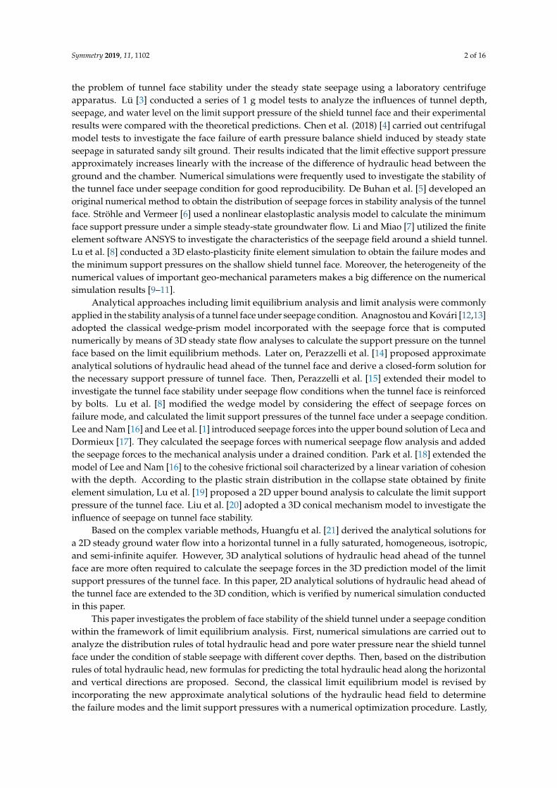
where h0 and hF denote the elevation of the water table and hydraulic head on the tunnel face,respectively. Additionally, r represents the radius of the tunnel.Symmetry 2019, 11, x FOR PEER REVIEW 10 of 16
D=2r
h0
z
x
Ch
hF T unnel face
Figure 7. Geometric diagram of the underwater tunnel.
Based on the distribution law of the total hydraulic head field near the shield tunnel face under a stable seepage condition under different buried depths, new formulas for predicting the total head field along horizontal and vertical directions were proposed. New approximate analytical solutions of hydraulic head field ahead of the tunnel face for a circular tunnel are shown in Equations (7) and (8).
2 22 2
00 2 22
2 2
178, , + ln17
2ln 1 8
F
h r x r h r hh h rh x y z h
h rh h x r h r hrr r
, (7)
2
2152 2 28
00 22 2 2
, , + ln
2 ln 1
r hz rr
Fz h r h rh h e
h x y z hh h z h r h rr r
, (8)
where h0 and hF denote the elevation of the water table and hydraulic head on the tunnel face, respectively. Additionally, r represents the radius of the tunnel.
Then the results obtained from Equations (7) and (8) were compared with the numerical simulation in this paper and existing predictions proposed by Perazzelli et al. [14] under C/D=1 and C/D=5. Figures 8 and 9 show the comparative results of the horizontal and vertical hydraulic head field, which indicates that those results are very similar with Perazzelli et al. [14] and demonstrates accuracy of the formula provided in this paper. It is worth noting that the numerical simulation and approximate formula proposed in this paper are based on the assumption of the circular tunnel, while the approximate formula in Reference [14] is based on the assumption of the rectangular tunnel.
0 20 40 60 80 100 120 140 160 180
0
10
20
30
40
50
60
70
80
90
100
110
Tota
l hea
d / m
x / m
Numerical simulation in this paper Approximate analytical solution [14] Approximate analytical solution in this paper
0 10 20 30 40 50 60 70 80 90 100 11010
11
12
13
14
15
16
17
18
19
20
z / m
Total head / m
Numerical simulation in this paper Approximate analytical solution [14] Approximate analytical solution in this paper
Figure 7. Geometric diagram of the underwater tunnel.
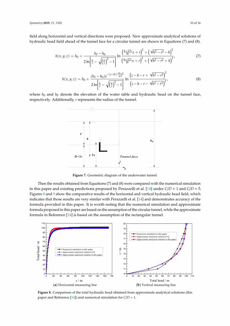
Then the results obtained from Equations (7) and (8) were compared with the numerical simulationin this paper and existing predictions proposed by Perazzelli et al. [14] under C/D = 1 and C/D = 5.Figures 8 and 9 show the comparative results of the horizontal and vertical hydraulic head field, whichindicates that those results are very similar with Perazzelli et al. [14] and demonstrates accuracy of theformula provided in this paper. It is worth noting that the numerical simulation and approximateformula proposed in this paper are based on the assumption of the circular tunnel, while the approximateformula in Reference [14] is based on the assumption of the rectangular tunnel.Symmetry 2019, 11, x FOR PEER REVIEW 11 of 17
(a) Horizontal measuring line (b) Vertical measuring line
Figure 8. Comparison of the total hydraulic head obtained from approximate analytical solutions (this paper and Reference [14]) and numerical simulation for C/D=1.
(a) Horizontal measuring line (b) Vertical measuring line
Figure 9. Comparison of the total hydraulic head obtained from approximate analytical solutions (this paper and Reference [14]) and numerical simulation for C/D=5.
3. Limit Equilibrium Model of the Tunnel Face Stability Considering the Effect of Seepage Forces
3.1. Outline
The limit equilibrium model composed of a prism and a wedge is illustrated in Figure 10. A tunnel of diameter D is constructed under a depth of cover C. The uniform support pressure σT is applied on the tunnel face to sustain stability. The effective weight of the soil is γ', the cohesion of the soil is c', the friction angle of the soil is φ', and the permeability of the soil is k0. As shown in Figure 8, the wedge is acted upon by the volume forces and the surface forces. The volume forces include its weight and seepage force, while the surface forces include the support force of the slurry on the tunnel face, the resultant normal forces, and shear forces along the failure surfaces ade, bcf, and abfe as well as the resultant vertical force of the prism at the interface defc.
0 20 40 60 80 100 120 140 160 1800
10
20
30
40
50
60
70
80
90
100
110
Tota
l hea
d / m
x / m
Numerical simulation in this paper Approximate analytical solution [14] Approximate analytical solution in this paper
0 10 20 30 40 50 60 70 80 90 100 11010
11
12
13
14
15
16
17
18
19
20
z / m
Total head / m
Numerical simulation in this paper Approximate analytical solution [14] Approximate analytical solution in this paper
0 20 40 60 80 100 120 140 160 1800
10
20
30
40
50
60
70
80
90
100
110
Tota
l hea
d / m
x / m
Numerical simulation in this paper Approximate analytical solution [14] Approximate analytical solution in this paper
0 10 20 30 40 50 60 70 80 90 100 11010
15
20
25
30
35
40
45
50
55
60
z / m
Total head / m
Numerical simulation in this paper Approximate analytical solution [14] Approximate analytical solution in this paper
Figure 8. Comparison of the total hydraulic head obtained from approximate analytical solutions (thispaper and Reference [14]) and numerical simulation for C/D = 1.

Symmetry 2019, 11, 1102 11 of 16
Symmetry 2019, 11, x FOR PEER REVIEW 11 of 17
(a) Horizontal measuring line (b) Vertical measuring line
Figure 8. Comparison of the total hydraulic head obtained from approximate analytical solutions (this paper and Reference [14]) and numerical simulation for C/D=1.
(a) Horizontal measuring line (b) Vertical measuring line
Figure 9. Comparison of the total hydraulic head obtained from approximate analytical solutions (this paper and Reference [14]) and numerical simulation for C/D=5.
3. Limit Equilibrium Model of the Tunnel Face Stability Considering the Effect of Seepage Forces
3.1. Outline
The limit equilibrium model composed of a prism and a wedge is illustrated in Figure 10. A tunnel of diameter D is constructed under a depth of cover C. The uniform support pressure σT is applied on the tunnel face to sustain stability. The effective weight of the soil is γ', the cohesion of the soil is c', the friction angle of the soil is φ', and the permeability of the soil is k0. As shown in Figure 8, the wedge is acted upon by the volume forces and the surface forces. The volume forces include its weight and seepage force, while the surface forces include the support force of the slurry on the tunnel face, the resultant normal forces, and shear forces along the failure surfaces ade, bcf, and abfe as well as the resultant vertical force of the prism at the interface defc.
0 20 40 60 80 100 120 140 160 1800
10
20
30
40
50
60
70
80
90
100
110
Tota
l hea
d / m
x / m
Numerical simulation in this paper Approximate analytical solution [14] Approximate analytical solution in this paper
0 10 20 30 40 50 60 70 80 90 100 11010
11
12
13
14
15
16
17
18
19
20
z / m
Total head / m
Numerical simulation in this paper Approximate analytical solution [14] Approximate analytical solution in this paper
0 20 40 60 80 100 120 140 160 1800
10
20
30
40
50
60
70
80
90
100
110To
tal h
ead
/ m
x / m
Numerical simulation in this paper Approximate analytical solution [14] Approximate analytical solution in this paper
0 10 20 30 40 50 60 70 80 90 100 11010
15
20
25
30
35
40
45
50
55
60
z / m
Total head / m
Numerical simulation in this paper Approximate analytical solution [14] Approximate analytical solution in this paper
Figure 9. Comparison of the total hydraulic head obtained from approximate analytical solutions (thispaper and Reference [14]) and numerical simulation for C/D = 5.
3. Limit Equilibrium Model of the Tunnel Face Stability Considering the Effect of Seepage Forces
3.1. Outline
The limit equilibrium model composed of a prism and a wedge is illustrated in Figure 10. A tunnelof diameter D is constructed under a depth of cover C. The uniform support pressure σT is appliedon the tunnel face to sustain stability. The effective weight of the soil is γ’, the cohesion of the soil isc’, the friction angle of the soil is ϕ’, and the permeability of the soil is k0. As shown in Figure 8, thewedge is acted upon by the volume forces and the surface forces. The volume forces include its weightand seepage force, while the surface forces include the support force of the slurry on the tunnel face,the resultant normal forces, and shear forces along the failure surfaces ade, bcf, and abfe as well as theresultant vertical force of the prism at the interface defc.Symmetry 2019, 11, x FOR PEER REVIEW 12 of 17
D=2r
h0
Ps
Pv
G
B=πD/4
Dz
yz
x
Fx
FzTs T
N
αa(b)
d(c)e(f )
b a
d(e)c(f )
Ch
hF
Figure 10. Failure mechanism of the tunnel face considering the effect of seepage forces.
3.2. Mechanical Analysis of the Prism
In the cover layer, the calculation of the distributed force acting on the truncated cone is obtained by modifying the original Terzaghi earth pressure theory considering the vertical seepage forces. Under the assumptions that water level is located at or above the soil surface, the cover layer above the tunnel is homogeneous and the ground in the cover layer obeys the Mohr-Coulomb failure criterion with the cohesion c' and the angle of internal friction φ′. The vertical equilibrium of an infinitesimal layer read as follows.
covtanvv w
d L idz A
, (9)
where A and L are the area and the circumference of a horizontal cross-section of the prism. icov can be calculated with the Equations (6) and (8).
Because of the complexity of the formula icov, the formula icov is divided into N segments along the depth direction and icov is assumed to be constant in each segment icov,i+1( 1...,,2,1,0 Ni ). Then Equation (9) can be written as shown below.
, 1 ,, cov, +1
tanv i v iv i w ii
z R
, (10)
Then the vertical stress ,v N can be obtained by iteration of Equation (10).
, 1 , cov, +1tan +1v i v i w iz i zR
. (11)
where
,0 =0v
3.3. Mechanical Analysis of the Wedge
According to the force equilibrium of the wedge:
s sin cos 2 coss xP N T T F , (12)
v cos sin 2 sinz sP G F N T T . (13)
where Ps is the support force, N is the normal force acting on the surface of the wedge, and G is the gravity of the wedge.
Figure 10. Failure mechanism of the tunnel face considering the effect of seepage forces.
3.2. Mechanical Analysis of the Prism
In the cover layer, the calculation of the distributed force acting on the truncated cone is obtainedby modifying the original Terzaghi earth pressure theory considering the vertical seepage forces. Underthe assumptions that water level is located at or above the soil surface, the cover layer above the tunnelis homogeneous and the ground in the cover layer obeys the Mohr-Coulomb failure criterion with the

Symmetry 2019, 11, 1102 12 of 16
cohesion c’ and the angle of internal friction ϕ′. The vertical equilibrium of an infinitesimal layer readas follows.
dσ′vdz− λ tanϕ′
LAσ′v = −γ′ − γwicov, (9)
where A and L are the area and the circumference of a horizontal cross-section of the prism. icov can becalculated with the Equations (6) and (8).
Because of the complexity of the formula icov, the formula icov is divided into N segments alongthe depth direction and icov is assumed to be constant in each segment icov,i+1 (i = 0, 1, 2, . . . , N − 1).Then Equation (9) can be written as shown below.
σ′v,i+1 − σ′v,i
∆z−λ tanϕ′
Rσ′v,i = −γ
′− γwicov,i+1, (10)
Then the vertical stress σ′v,N can be obtained by iteration of Equation (10).
σ′v,i+1 =
(λ tanϕ′
R∆z + 1
)σ′v,i + (−γ′ − γwicov,i+1)∆z. (11)
whereσ′v,0 = 0.
3.3. Mechanical Analysis of the Wedge
According to the force equilibrium of the wedge:
Ps = N sinα− T cosα− 2Ts cosα+ Fx, (12)
Pv + G + Fz = N cosα+ T sinα+ 2Ts sinα. (13)
where Ps is the support force, N is the normal force acting on the surface of the wedge, and G is thegravity of the wedge.
The gravity G is:
G =πγ′D3
8 tanα, (14)
The total shear force T on the slope of the wedge is:
T = N tanϕ′ +c′πD2
4 sinα, (15)
The total lateral shear force Ts on the wedge is then obtained:
Ts =D2
2 tanα
(c + λ tanϕ′
2σ′v + Dγ′
3
), (16)
By Gaussian integration, the volume integral is converted to a surface integral, and the horizontalseepage forces Fx in the wedge block are shown below.
Fx = γw
xabcd
h(x, y, z)ds− sinαx
abe f
h(x, y, z)ds
, (17)

Symmetry 2019, 11, 1102 13 of 16
3.4. Calculation of Limit Support Pressure
By solving Equations (12) and (13), the limit support pressure, which is used to stabilize the tunnelface, is calculated by using Equation (18). Then the critical inclination αcr. is determined by iterativelymaximizing the necessary support force.
σs = f1c′ + f2γ′D + f3σv + f4Fz + f5Fx, (18)
where the coefficients f 1, f 2, f 3, f 4, and f 5 are:
f1 = −1+tan(α−ϕ) tanα
tanα −M0
f2 =tan(α−ϕ)
2 tanα −M0λ tanϕ
3
f3 =tan(α−ϕ)
tanα −2M0λ tanϕ
3
f4 =4 tan(α−ϕ)
πD2
f5 = 4πD2
M0 =4 cosα[cotα+tan(α−ϕ)]
π
, (19)
4. Comparison of the Limit Support Pressures with the Existing Approaches
The results obtained from the theoretical analysis model developed in this paper were validatedby comparisons with existing approaches (Lee et al. [1] and Perazzelli et al. [14]). The tunnel diameterD is 5 m, and the cover depths C are 10, 15, and 20 m assuming that the water table is located at thesoil surface (i.e., h0 = C + D). The cohesion and friction angle of soil are 0 kPa and 35◦. The dry andsubmerged gravities of the soil are 15.2 kN/m3 and 5.4 kN/m3. As shown in Figure 11, the calculatedlimit support pressure increases linearly with the water table. Moreover, the results from this paperwere between the results from Perazzelli et al. [14] (the highest solutions) and from Lee et al. [1] (thelowest solutions).Symmetry 2019, 11, x FOR PEER REVIEW 14 of 17
Figure 11. Comparisons of limit support pressure with variation of the C/D ratio.
5. Sensitivity Analysis of Model Parameters on the Limit Support Pressures
5.1. Influence of the Variables of the Hydraulic Head on Limit Support Pressures
Figure △12 describes the influence of h/D on the normalized effective limit support pressures σ'T/(γ'D) with a different effective friction angle of the soil φ'. The tunnel diameter D is 10 m and the cover depth C is 10 m. Hydraulic head h0 are 20 m, 40 m, 60 m, 80 m, and 100 m. The effective friction angle of soil are 15°, 20°, 25°, 30°, and 35°. Submerged unit weight of the soil is 10 kN/m3.
As shown in Figure 12, when the buried depth ratio is the same, the normalized effective limit support pressures of the shield tunnel face increases linearly with the increase of hydraulic head. Moreover, the higher the effective friction angle of the soil is, the lower the normalized effective limit support pressures are.
Figure 12. Influence of h/D on the normalized effective limit support pressures σ'T/(γ'D).
5.2. Influence of the Variables of the C/D on Limit Support Pressures
Figure 13 describes the influence of C/D on the normalized effective limit support pressures σ'T/(γ'D) with a different effective friction angle of the soil φ'. The tunnel diameter D is 10 m, and the cover depths C are 10, 20, 30, 40, and 50 m. Hydraulic head h0 is 100 m. The effective friction angle of soil are 15°, 20°, 25°, 30°, and 35°. Submerged unit weight of the soil is 10 kN/m3.
As shown in Figure 13, when the hydraulic head is the same, the normalized effective limit support pressures of the shield tunnel face decreases nonlinearly with the increase of the buried
2.0 2.5 3.0 3.5 4.0
40
44
48
52
56
60
64
68
T (
kN/m
2 )
C / D
Perazzelli et al. (2014) Lee et al. (2003) This paper
2 3 4 5 6 7 8 9 100
1
2
3
4
5
6
7
8
' T /
(D
)
Δh / D
= 15 = 20 = 25 = 30 = 35
Figure 11. Comparisons of limit support pressure with variation of the C/D ratio.
5. Sensitivity Analysis of Model Parameters on the Limit Support Pressures
5.1. Influence of the Variables of the Hydraulic Head on Limit Support Pressures
Figure 12 describes the influence of ∆h/D on the normalized effective limit support pressuresσ’T/(γ’D) with a different effective friction angle of the soil ϕ’. The tunnel diameter D is 10 m and the

Symmetry 2019, 11, 1102 14 of 16
cover depth C is 10 m. Hydraulic head h0 are 20 m, 40 m, 60 m, 80 m, and 100 m. The effective frictionangle of soil are 15◦, 20◦, 25◦, 30◦, and 35◦. Submerged unit weight of the soil is 10 kN/m3.
Symmetry 2019, 11, x FOR PEER REVIEW 14 of 17
Figure 11. Comparisons of limit support pressure with variation of the C/D ratio.
5. Sensitivity Analysis of Model Parameters on the Limit Support Pressures
5.1. Influence of the Variables of the Hydraulic Head on Limit Support Pressures
Figure △12 describes the influence of h/D on the normalized effective limit support pressures σ'T/(γ'D) with a different effective friction angle of the soil φ'. The tunnel diameter D is 10 m and the cover depth C is 10 m. Hydraulic head h0 are 20 m, 40 m, 60 m, 80 m, and 100 m. The effective friction angle of soil are 15°, 20°, 25°, 30°, and 35°. Submerged unit weight of the soil is 10 kN/m3.
As shown in Figure 12, when the buried depth ratio is the same, the normalized effective limit support pressures of the shield tunnel face increases linearly with the increase of hydraulic head. Moreover, the higher the effective friction angle of the soil is, the lower the normalized effective limit support pressures are.
Figure 12. Influence of h/D on the normalized effective limit support pressures σ'T/(γ'D).
5.2. Influence of the Variables of the C/D on Limit Support Pressures
Figure 13 describes the influence of C/D on the normalized effective limit support pressures σ'T/(γ'D) with a different effective friction angle of the soil φ'. The tunnel diameter D is 10 m, and the cover depths C are 10, 20, 30, 40, and 50 m. Hydraulic head h0 is 100 m. The effective friction angle of soil are 15°, 20°, 25°, 30°, and 35°. Submerged unit weight of the soil is 10 kN/m3.
As shown in Figure 13, when the hydraulic head is the same, the normalized effective limit support pressures of the shield tunnel face decreases nonlinearly with the increase of the buried
2.0 2.5 3.0 3.5 4.0
40
44
48
52
56
60
64
68
T (
kN/m
2 )
C / D
Perazzelli et al. (2014) Lee et al. (2003) This paper
2 3 4 5 6 7 8 9 100
1
2
3
4
5
6
7
8
' T /
(D
)
Δh / D
= 15 = 20 = 25 = 30 = 35
Figure 12. Influence of ∆h/D on the normalized effective limit support pressures σ’T/(γ’D).
As shown in Figure 12, when the buried depth ratio is the same, the normalized effective limitsupport pressures of the shield tunnel face increases linearly with the increase of hydraulic head.Moreover, the higher the effective friction angle of the soil is, the lower the normalized effective limitsupport pressures are.
5.2. Influence of the Variables of the C/D on Limit Support Pressures
Figure 13 describes the influence of C/D on the normalized effective limit support pressuresσ’T/(γ’D) with a different effective friction angle of the soil ϕ’. The tunnel diameter D is 10 m, and thecover depths C are 10, 20, 30, 40, and 50 m. Hydraulic head h0 is 100 m. The effective friction angle ofsoil are 15◦, 20◦, 25◦, 30◦, and 35◦. Submerged unit weight of the soil is 10 kN/m3.
Symmetry 2019, 11, x FOR PEER REVIEW 15 of 17
depth ratio. It should be noted that, with the same hydraulic head, the small buried depth of the shield tunnel leads to the larger horizontal hydraulic gradient in front of the tunnel face (c.f. Figure 5 or Section 2 in Reference [14]) and the greater the horizontal infiltration force in front of tunnel excavation, which means the larger limit support pressures. Similarly, the higher the effective friction angle of the soil, the lower the normalized effective limit support pressures will be.
Figure 13. Influence of C/D on the normalized effective limit support pressures σ'T/(γ'D).
6. Conclusions
This paper investigates the problem of the face stability of the shield tunnel under a seepage condition within the framework of limit equilibrium analysis. First, numerical simulations are carried out in this paper to analyze the distribution rules of total hydraulic head, pore water pressure, and a hydraulic gradient near the shield tunnel face under the condition of stable seepage with different cover depths. Then, based on the distribution rules of total hydraulic head, new formulas for predicting the total hydraulic head along the horizontal and vertical directions are proposed and compared with the numerical simulations in this paper and existing approximate analytical solutions. Second, the classical limit equilibrium model is revised by incorporating the new approximate analytical solutions of the hydraulic head field to determine the failure modes and the limit support pressures with a numerical optimization procedure. Lastly, the comparisons of the results obtained from the theoretical analysis in this paper and the existing approaches are conducted. The main conclusions are shown below.
(1) The distribution law of total hydraulic head field along the horizontal distance at the axis of the shield tunnel is analyzed. The results show that the distribution of total hydraulic head at the axis of the shield tunnel face along the horizontal distance is a "negative exponential" function. The distribution law of total hydraulic head along the depth direction of the shield tunnel in front of the tunnel face on the vertical symmetrical surface is analyzed. The results indicate that the distribution of total hydraulic head along the depth is nonlinear when the tunnel is close to the tunnel face.
(2) The comparative results of the horizontal and vertical hydraulic head field with the numerical simulations in this paper and existing approximate analytical solutions demonstrate accuracy of the formula proposed in this paper.
(3) Comparisons of the results of limit support pressure obtained from the theoretical analysis in this paper and the existing approaches show that the failure mechanism proposed in this paper could provide relatively satisfactory results for the limit support pressures applied to the tunnel face.
(4) When the buried depth ratio is the same, the normalized effective limit support pressures of the shield tunnel face increases linearly with the rise of the hydraulic head. When the hydraulic head is the same, the normalized effective limit support pressures of the shield tunnel face decreases nonlinearly with the
1 2 3 4 52
3
4
5
6
7
8
9
' T /
(D
)
C / D
= 15 = 20 = 25 = 30 = 35
Figure 13. Influence of C/D on the normalized effective limit support pressures σ’T/(γ’D).
As shown in Figure 13, when the hydraulic head is the same, the normalized effective limitsupport pressures of the shield tunnel face decreases nonlinearly with the increase of the buried depthratio. It should be noted that, with the same hydraulic head, the small buried depth of the shield tunnelleads to the larger horizontal hydraulic gradient in front of the tunnel face (c.f. Figure 5 or Section 2 in

Symmetry 2019, 11, 1102 15 of 16
Reference [14]) and the greater the horizontal infiltration force in front of tunnel excavation, whichmeans the larger limit support pressures. Similarly, the higher the effective friction angle of the soil,the lower the normalized effective limit support pressures will be.
6. Conclusions
This paper investigates the problem of the face stability of the shield tunnel under a seepagecondition within the framework of limit equilibrium analysis. First, numerical simulations are carriedout in this paper to analyze the distribution rules of total hydraulic head, pore water pressure, anda hydraulic gradient near the shield tunnel face under the condition of stable seepage with differentcover depths. Then, based on the distribution rules of total hydraulic head, new formulas for predictingthe total hydraulic head along the horizontal and vertical directions are proposed and comparedwith the numerical simulations in this paper and existing approximate analytical solutions. Second,the classical limit equilibrium model is revised by incorporating the new approximate analyticalsolutions of the hydraulic head field to determine the failure modes and the limit support pressureswith a numerical optimization procedure. Lastly, the comparisons of the results obtained from thetheoretical analysis in this paper and the existing approaches are conducted. The main conclusions areshown below.
(1) The distribution law of total hydraulic head field along the horizontal distance at the axis of theshield tunnel is analyzed. The results show that the distribution of total hydraulic head at theaxis of the shield tunnel face along the horizontal distance is a “negative exponential” function.The distribution law of total hydraulic head along the depth direction of the shield tunnel in frontof the tunnel face on the vertical symmetrical surface is analyzed. The results indicate that thedistribution of total hydraulic head along the depth is nonlinear when the tunnel is close to thetunnel face.
(2) The comparative results of the horizontal and vertical hydraulic head field with the numericalsimulations in this paper and existing approximate analytical solutions demonstrate accuracy ofthe formula proposed in this paper.
(3) Comparisons of the results of limit support pressure obtained from the theoretical analysis in thispaper and the existing approaches show that the failure mechanism proposed in this paper couldprovide relatively satisfactory results for the limit support pressures applied to the tunnel face.
(4) When the buried depth ratio is the same, the normalized effective limit support pressures of theshield tunnel face increases linearly with the rise of the hydraulic head. When the hydraulic headis the same, the normalized effective limit support pressures of the shield tunnel face decreasesnonlinearly with the increase of the buried depth ratio. Moreover, the higher the effective frictionangle of the soil, the lower the normalized effective limit support pressures will be.
Author Contributions: L.W. and K.H. conceived of the idea of using a limit equilibrium model and numericalsimulation to analyze the problem of the face stability of the shield tunnel under a seepage condition. T.X. and J.L.completed most of the details of the calculations.
Funding: The National Natural Science Foundation of China (Grant no. 51908371) provided financial support forthe authors.
Conflicts of Interest: The authors declare no conflict of interest.
References
1. Lee, I.M.; Nam, S.W.; Ahn, J.H. Effect of seepage forces on tunnel face stability. Can. Geotech. J. 2003, 40,342–350. [CrossRef]
2. Tang, L.J. Numerical Investigations and Centrifugal Model Tests on Face Stability of Shield Tunnel in Dryand Saturated Sandy Soils. Ph.D. Thesis, Zhejiang University, Hangzhou, China, 2014. (In Chinese)
3. Lü, X.; Zhou, Y.; Huang, M.; Zeng, S. Experimental study of the face stability of shield tunnel in sands underseepage condition. Tunn. Undergr. Space Technol. 2018, 74, 195–205. [CrossRef]

Symmetry 2019, 11, 1102 16 of 16
4. Chen, R.P.; Yin, X.S.; Tang, L.J.; Chen, Y.M. Centrifugal model tests on face failure of earth pressure balanceshield induced by steady state seepage in saturated sandy silt ground. Tunn. Undergr. Space Technol. 2018, 81,315–325. [CrossRef]
5. DE Buhan, P.; Cuvillier, A.; Dormieux, L.; Maghous, S. Face stability of shallow circular tunnels driven underthe water table: A numerical analysis. Int. J. Numer. Anal. Met. 1999, 23, 79–95. [CrossRef]
6. Ströhle, P.M.; Vermeer, P.A. Tunnel face stability with groundwater flow. In Proceedings of the 7th EuropeanConference on Numerical Methods in Geotechnical Engineering, Trondheim, Norway, 2–4 June 2010; CRC Press(Taylor & Francis): London, UK, 2010; pp. 813–818.
7. Li, C.L.; Miao, L.C. Finite element simulation of seepage field and analysis of soil deformation around tunneldue to shield tunneling. J. Southeast Univ. (Nat. Sci. Ed.) 2010, 40, 1066–1072. (In Chinese)
8. Lu, X.; Zhou, Y.; Huang, M.; Li, F. Computation of the minimum limit support pressure for the shield tunnelface stability under seepage condition. Int. J. Civ. Eng. 2017, 15, 849–863. [CrossRef]
9. Calista, M.; Pasculli, A.; Sciarra, N. Reconstruction of the geotechnical model considering random parametersdistributions. In Engineering Geology for Society and Territory; Springer International Publishing: Heidelberg,Germany, 2015; Volume 2, pp. 1347–1351.
10. Vu-Bac, N.; Lahmer, T.; Zhuang, X.; Nguyen-Thoi, T.; Rabczuk, T. A software framework for probabilisticsensitivity analysis for computationally expensive models. Adv. Eng. Softw. 2016, 100, 19–31. [CrossRef]
11. Pasculli, A.; Calista, M.; Sciarra, N. Variability of local stress states resulting from the application of MonteCarlo and finite difference methods to the stability study of a selected slope. Eng. Geol. 2018, 245, 370–389.[CrossRef]
12. Anagnostou, G.; Kovári, K. The face stability of slurry-shield-driven tunnels. Tunn. Undergr. Space Technol.1994, 9, 165–174. [CrossRef]
13. Anagnostou, G.; Kovari, K. Face stability conditions with earth-pressure-balanced shields. Tunn. Undergr.Space Technol. 1996, 11, 165–173. [CrossRef]
14. Perazzelli, P.; Leone, T.; Anagnostou, G. Tunnel face stability under seepage flow conditions. Tunn. Undergr.Space Technol. 2014, 43, 459–469. [CrossRef]
15. Perazzelli, P.; Cimbali, G.; Anagnostou, G. Stability under seepage flow conditions of a tunnel face reinforcedby bolts. Procedia Eng. 2017, 191, 215–224. [CrossRef]
16. Lee, I.M.; Nam, S.W. The study of seepage forces acting on the tunnel lining and tunnel face in shallowtunnels. Tunn. Undergr. Space Technol. 2001, 16, 31–40. [CrossRef]
17. Leca, E.; Dormieux, L. Upper and lower bound solutions for the face stability of shallow circular tunnels infrictional material. Géotechnique 1990, 40, 581–606. [CrossRef]
18. Park, J.K.; Blackburn, J.T.; Ahn, J.H. Upper bound solutions for tunnel face stability considering seepage andstrength increase with depth. In Proceedings of the Underground Space the 4th Dimension of Metropolises,Prague, Czech Republic, 5–10 May 2007; pp. 1217–1222.
19. Lu, X.L.; Wang, H.R.; Huang, M.S. Upper bound solution for the face stability of shield tunnel below thewater table. Math. Probl. Eng. 2014, 727964. [CrossRef]
20. Liu, W.; Albers, B.; Zhao, Y.; Tang, X.W. Upper bound analysis for estimation of the influence of seepage ontunnel face stability in layered soils. J. Zhejiang Univ.-Sci. A 2016, 17, 886–902. [CrossRef]
21. Huangfu, M.; Wang, M.S.; Tan, Z.S.; Wang, X.Y. Analytical solutions for steady seepage into an underwatercircular tunnel. Tunn. Undergr. Space Technol. 2010, 25, 391–396. [CrossRef]
22. Liu, W.; Zhang, X.J.; Tang, X.W.; Chen, R.P. Supporting pressure for earth pressure balance tunnel facestability when tunneling is implemented in saturated sandy soil. J. Zhejiang Univ. (Eng. Sci.) 2012, 46,664–704. (In Chinese)
23. Lei, H.B. Numerical Simulation and Approximate Analytical Solution for Groundwater Flow in Vicinity ofthe Face of Shield Tunnel Excavations. Master’s Thesis, Beijing Jiaotong University, Beijing, China, 2016. (InChinese)
© 2019 by the authors. Licensee MDPI, Basel, Switzerland. This article is an open accessarticle distributed under the terms and conditions of the Creative Commons Attribution(CC BY) license (http://creativecommons.org/licenses/by/4.0/).