calix 844e gigacenter user guide · 2018-06-28 · calix 844e gigacenter user guide # 220-00824,...
TRANSCRIPT

Calix 844E GigaCenter User Guide
# 220-00824, Rev 12
February, 2017


3
Proprietary Information: Not for use or disclosure except by written agreement with Calix. .
Contents
About this Guide ...................................................................... 6
Intended Audience .................................................................................................... 6
Related Documentation ............................................................................................ 6
Conventions .............................................................................................................. 7
Chapter 1 844E GigaCenter Overview .................................. 9
GigaCenter Models ................................................................................................. 12
Hardware Installation .............................................................................................. 13
Chapter 2 Embedded Web Interface ................................... 15
About Carrier Grade IPTV over Wi-Fi .................................................................... 16
GigaCenter Platform Support ................................................................................ 16
About the Home Gateway ...................................................................................... 17
GigaCenter System Architecture ........................................................................... 19
GigaCenter Inventory ............................................................................................. 20
About GigaCenter Resets ...................................................................................... 21
Connecting to the GigaCenter Home Gateway EWI - Subscriber ....................... 22
GigaCenter Management Model ............................................................................ 22
GigaFamily Management ............................................................................... 23
Home Gateway IPv6 Support ................................................................................. 23
Dual Stack IPv4/IPv6 ..................................................................................... 25 DS-Lite ........................................................................................................... 25 6rd .................................................................................................................. 26
GigaCenter Voice Services .................................................................................... 28

4
Proprietary Information: Not for use or disclosure except by written agreement with Calix. .
Chapter 3 Wireless Networking ........................................... 29
About the 5 GHz Wi-Fi Radio ................................................................................. 29
Wireless Network Performance ............................................................................. 30
About Multiple Input, Multiple Output (MIMO) Streams ....................................... 32
About Beamforming ............................................................................................... 32
About the 2.4 GHz and 5.0 GHz Spectrums .......................................................... 33
Carrier Class Wi-Fi Quality of Service (QoS) ........................................................ 36
Getting Additional Information .............................................................................. 36
Chapter 4 GigaCenter Operations ....................................... 37
Turning up a GigaCenter ........................................................................................ 37
Connecting for the First Time ......................................................................... 38 Configuring your Wireless Network ................................................................ 40 Setting the Time Zone .................................................................................... 41 Wireless Radio Configuration ......................................................................... 41 GigaCenter Utilities ........................................................................................ 45 Advanced Menu ............................................................................................. 49 LED Behavior ................................................................................................. 58 Configuring Home Gateway Applications ....................................................... 67 Home Gateway Configuration via Local Access............................................. 68 Supported and Unsupported Use Cases ........................................................ 69
Appendix A Appendix .......................................................... 71
Embedded Web Interface Field Definitions ......................... 71
Status Menu ............................................................................................................ 74
Status Menu Overview ............................................................................................ 74
Connections ................................................................................................... 75 Devices .......................................................................................................... 77 Internet ........................................................................................................... 79 Ethernet ......................................................................................................... 81 Wireless ......................................................................................................... 82 NAT (Network Address Translation) ............................................................... 84 Routing ........................................................................................................... 85
5
Proprietary Information: Not for use or disclosure except by written agreement with Calix. .
Security .......................................................................................................... 86
Quick Start Menu .................................................................................................... 87
Quick Start Menu Overview ................................................................................... 87
Connect to Internet ......................................................................................... 88 Configure Wireless Network ........................................................................... 89 Set Time Zone................................................................................................ 91
Wireless Menu ......................................................................................................... 92
Wireless Menu Overview ........................................................................................ 93
Radio Setup ................................................................................................... 94 SSID Setup .................................................................................................... 96 Wireless Security ........................................................................................... 98 MAC Authentication ....................................................................................... 99 WMM (Wi-Fi Multimedia) .............................................................................. 100 Advanced Radio Set-up ............................................................................... 101 WPS (Wi-Fi Protected Setup) ...................................................................... 101
Utilities Menu ........................................................................................................ 103
Utilities Menu Overview ........................................................................................ 104
Configuration Save ....................................................................................... 105 Upgrade Image ............................................................................................ 107 Restore Defaults .......................................................................................... 108 Reboot ......................................................................................................... 109 Web Activity Log .......................................................................................... 109 Ping Test ...................................................................................................... 111 Traceroute .................................................................................................... 113 System Log .................................................................................................. 114 Firewall Log .................................................................................................. 116
Advanced Menu .................................................................................................... 117
Scheduling and Blocking Overview .............................................................. 118 IP Addressing Overview ............................................................................... 125 Static Routing ............................................................................................... 133 Quality of Service Overview ......................................................................... 134 Security Overview ........................................................................................ 136 Change in Behavior ...................................................................................... 141 Remote Management Overview ................................................................... 149

6
Proprietary Information: Not for use or disclosure except by written agreement with Calix. .
About this Guide
This Calix 844E GigaCenter Users Guide provides instructions for managing GigaCenters via the on-line Embedded Web Interface (EWI). The EWI controls and manages network operations when used in conjunction with various Calix GigaCenter devices. This guide explains how to set up and maintain Ethernet network settings and any subtended subscriber devices attached to GigaCenter.
Note: This guide is intended to educate the user in set-up and ongoing administration of the Calix GigaCenter and associated sub-tended devices. This guide does not address the provisioning of services on the GigaCenters themselves. For information on service provisioning, refer to the appropriate platform specific User's Guide.
Intended Audience This guide is intended for use by consumers. Basic knowledge of Internet Protocol (IP) based systems as well as a general understanding of IP addressing, routing principles, and internet security are also highly desired. This document assumes that the user's PC is equipped with a supported web browser (Internet Explorer, Firefox, Chrome, or Safari) and that the user is familiar with using a web browser. Familiarity with datacom, telecom, and standards-based Ethernet technologies and conventions is recommended.
Related Documentation You can access Calix product documentation by logging into My Calix (www.calix.com/my-calix (https://www.calix.com/my-calix)) and browsing the My Calix Documentation Library.
The Calix GigaCenter documentation set includes:
Calix 844E GigaCenter User's Guide (this document) Calix 844E GigaCenter Installation Guide Calix Residential Service Gateway (RSG) Wi-Fi Best Practices Guide

7
Proprietary Information: Not for use or disclosure except by written agreement with Calix. .
Conventions
Document Conventions
For this application guide, when the term GigaCenter is used all devices in the GigaCenter family support the feature or behavior. When a specific product like the 844E is explicitly called out, it means the behavior/capability is specific to that model.
Site Conventions
The following elements and controls are used consistently throughout the Graphical User Interface for the 844E GigaCenter:
Website Display Elements Example Icon Element Name Description
Action Button May include Edit, Add, Remove
Radio Button Typically offers a choice between two options
Check Box Typically used to enable or disable a
feature
Drop-down List Provides a pre-existing list from which to choose
Alpha-text Box Alpha-numeric input box typically used for naming a function, port, service, or device. Note: Values exceeding field length maximums are truncated at the max field length.
Numeric-text Box Numeric input box typically used for naming a function, port, service, or device Note: Invalid entries return a "value out of range" error message.
System Defaults
Fields that carry a pre-defined default values are marked with an "‡" symbol in the last column of each table.

8
Proprietary Information: Not for use or disclosure except by written agreement with Calix. .
Username and Passwords
Within the EWI, there are several screens that require the entry of a user name and password. The following table details the allowable syntax for each username/password combination.
Username and Password Handling
Username Field Password Field
Page Location Min. Char.
Max. Char.
Validity Min. Char.
Max. Char.
Validity
Advanced > IP Addressing > Dynamic DNS
1 64 Allowed: A-Z, a-z, 0-9 1 32 Not allowed: ^<>()"%&'+;
Advanced > IP Addressing > WAN Settings
0 256 Not allowed: ~`!#$%^&*()-_+={}[]|\:;"?/
0 32 No restrictions
Advanced > Remote Management > Remote GUI
1 15 Allowed: A-Z, a-z, 0-9, !*()-_. 1 15 Allowed: A-Z, a-z, 0-9, !*()-_.
Advanced > Remote Management > Remote Telnet
1 15 Allowed: A-Z, a-z, 0-9, !*()-_. 1 15 Allowed: A-Z, a-z, 0-9, !*()-_.
Advanced > Security > Administrator Credentials
1 64 Allowed: A-Z, a-z, 0-9, !*()-_. 0 32 Allowed: A-Z, a-z, 0-9, !*()-_.
Quick Start > Connect to Internet
0 256 Not allowed: ~`!#$%^&*()-_+={}[]|\:;"?/
0 32 No restrictions
Support > TR-069 1 any Not allowed: spaces 1 32 Not allowed: spaces

Proprietary Information: Not for use or disclosure except by written agreement with Calix. .
Chapter 1
844E GigaCenter Overview
The Calix 844E GigaCenter represents an important addition to the family of Premises delivery platforms optimized to extend the network demarcation inside the subscriber’s home. The 844E GigaCenter is the first Calix Premises product to support service applications when subtended from an access device such as an ONT. The 844E continues support of carrier class Wi-Fi using 802.11ac technology, allowing all services to be delivered over a wireless network including IPTV. With integrated Carrier Class Wi-Fi, the 844E GigaCenter incorporates:
• 4x4 Multiple-Input-Multiple-Output (MIMO) at 5 GHz
• Support of the entire 5 GHz band including Dynamic Frequency Selection (DFS) channels
• Implicit and explicit beamforming
• Use of 80MHz combined channels at 5 GHz
• Software management tools and quality of service capabilities
Note: The initial release of the 844E is targeted for Calix fiber deployments with the 844E subtended from a Calix ONT.

10
Proprietary Information: Not for use or disclosure except by written agreement with Calix. .
844E GigaCenters
The 844E GigaCenter supports the same Home Gateway functionality as the 844G and 854G GigaCenters. It supports dual-band concurrent 2.4 GHz and 5 GHz Wi-Fi, allowing continued usage of the 2.4 GHz band for data and legacy consumer devices while supporting IPTV and high-speed data at 5 GHz. When connected to a Calix GPON ONT providing Layer-2 access and security along with carrier-grade voice, the 844E helps meet service providers’ and end-users’ requirements for ubiquitous broadband access throughout the residence driven by the growth of smart mobile devices and media rich content. These Wi-Fi devices range from low bandwidth IP cameras, security sensors, smart phones, tablets, and printers, as well as support for bandwidth intensive Quality Of Service (QoS) sensitive Wi-Fi capable Set Top Boxes (STBs) and TVs.
The 844E GigaCenter includes the following features:
• The 844E operates independently of the access link, whether it is a Calix GPON or AE ONT. It does not require OLT software support and therefore can be used for E7, C7, B6 and BLM-1500 deployments. As noted above, an 844E is very flexible and can support many deployment scenarios.
Note: With the initial release of the 844E, the supported deployment model is to subtend it behind a Calix GPON ONT. All other deployment scenarios will be evaluated on a case by case basis. The 844E does not provide any Layer-2 access features such as downstream or upstream bandwidth management, MACFF, L2 Source Verify, and L2 security features such as broadcast limiters.
• Support of the latest 802.11ac standard for the 5GHz radio. Some basic 802.11ac enhancements include:
Dynamic beamforming for high performance and longer reaches
80Mhz channels for greater speeds
QoS support allowing prioritization of Video Service Set Indentifier (SSID) over lower priority best effort High Speed Internet (HSI) data SSIDs
Dual band concurrent radios allow the subscriber to use legacy 2.4 GHz clients while accessing seven times the spectrum of 2.4 GHz using the 5 GHz band.
The 844E-1 ANSI versions, both 2.4 GHz and 5 GHz Wi-Fi radios operate at the maximum conductive emissions allowed by the FCC. The 844E high power 2.4 GHz radio is combined with a higher power 5 GHz radio with beamforming gain from the 4x4 antennas for an effective power increase.
GigaCenter 5 GHz radio was designed for critical IPTV services and supports channel hoping during operation, thereby avoiding service disruption due to interference.
GigaCenters 5 GHz radio is FCC certified to use the Dynamic Frequency Selection (DFS) channels which comprise 60% of the 5 GHz channels. These are largely unused frequencies as commercial routers sold over retail counters generally are not certified to operate with these channels.

11
Proprietary Information: Not for use or disclosure except by written agreement with Calix. .
Note: Not all Wi-Fi capable clients and devices support the DFS channels. Service providers will need to enable DFS support if they do not expect to encounter DFS interoperability issues with subscribers.
GigaCenters 5 GHz radio has a Wi-Fi QoS feature that can be assigned to different SSIDs. For the current release, IPTV services are assigned to a pre-defined video SSID called "5 GHz_IPTV_SSID" with usage and QOS pre-configured. This allows this pre-defined IPTV SSID to be prioritized over best effort data services assigned to other 5 GHz SSIDs.
The GigaCenters Carrier Class 5 GHz radio covers 95% of standard U.S. homes supporting 8 STB clients using 4x4 Quantenna radios. In other words the use case is defined as supporting 8 simultaneous HD video channels to 8 STBs located throughout a home with additional bandwidth reserved for HSI data applications using the 5 GHz band (the industry definition of carrier
The 844E has a 10/100/1000BaseT Ethernet WAN interface that connects downstream from a Calix ONT or third-party access device. In absence of any bandwidth management, it is capable of switching and routing functions that manage premises network traffic at 1 Gbps. The 844E LAN side interfaces include:
(4) Gigabit Ethernet (GE) ports for IPTV and data services
(2) integrated voice lines supporting SIP based VoIP
Wireless networking support for 802.11b/g/n/ac
A USB port for future emerging smart home services.
2-pin barrel connector and power switch
Note: The 844E does not include the ability to connect to a UPS.
Local management is accomplished using the Home Gateway locally hosted Embedded Web Interface (EWI).
Note: All GigaCenter products are intended for use in residential whole home Wi-Fi deployments supporting HSI and IPTV delivery over the 2.4 GHz or 5 GHz wireless network.

12
Proprietary Information: Not for use or disclosure except by written agreement with Calix. .
GigaCenter Models The 844E is designed to support the same level of carrier class Wi-Fi as the 844G and 854G products, delivering in-home wireless broadband coverage, quality of service, and speed. All GigaCenters use the latest 802.11ac 5 GHz band Wi-Fi technology with 4x4 Multiple Input Multiple Output (MIMO) and beam forming. GigaCenter allows service providers to deliver carrier class speeds and ubiquitous coverage to wirelessly connected devices in use throughout the subscriber home, and deliver symmetric broadband data rates of up to one gigabit per second (Gbps) to wired devices.
The initial release of the Calix 844E GigaCenter includes two version designed to meet specific needs of the market. The table below highlights the differences between these models. In general the "-1"models are intended for ANSI/North American markets which have requirements for loss of commercial power applications and the "-2" are purpose built for ETSI/International markets that don’t have loss of commercial power needs.
Calix 844E GigaCenter Models Attribute 844E-1 (ANSI) 844E-2 (ETSI)
WAN Interface Ethernet Ethernet
CE Marking No Yes
UL Marking Yes Yes
POTS (FXS) 2 2
10/100/1000 Ethernet 4 4
Dual-band Concurrent Wi-Fi Yes Yes
2.4 GHz Wi-Fi (MIMO) FCC Conductive Emissions EIRP
2 x 2 30 dBm/1 W 32 dBm/1.6 W
2 x 2 14 dBm/50 mW 20 dBm/100 mW
5 GHz Wi-Fi (MIMO) FCC Conductive Emissions EIRP
4 x 4 30 dBm/1 W 35 dBm/3 W
4 x 4 27 dBm/500 mW 30 dBm/1 W
RF Output No No
External Power Switch Yes Yes
Input Power Connector Type 2-pin Coaxial Barrel 2-pin Coaxial Barrel

13
Proprietary Information: Not for use or disclosure except by written agreement with Calix. .
Hardware Installation All GigaCenter units ship with both a wall bracket and desktop stand for use by installers. For optimal wireless performance and to assure proper ventilation the GigaCenter must be installed vertically at a desktop or media center location using the desktop stand, or mounted to a wall in a vertical or horizontal orientation (LEDs facing up).
Wall Mount Vertical Wall Mount Horizontal
Table Top Mount Wall Mount Tray and Base Stand (Included)
Note: The GigaCenter product family are not to be installed or operated in a flat orientation on a desktop or ceiling. GigaCenters cannot be wall-mounted upside down (LEDs facing down, cables facing up) or inverted (LEDs facing right, cables facing right). For complete installation information, refer to the 844E GigaCenter Installation Guide.

14
Proprietary Information: Not for use or disclosure except by written agreement with Calix. .

Proprietary Information: Not for use or disclosure except by written agreement with Calix. .
Chapter 2
Embedded Web Interface The Embedded Web Interface (EWI) is available for viewing and managing GigaFamily devices through your personal computers browser. The EWI allows you to login into any Home Gateway connected GigaFamily device using its IP Address and the appropriate login credentials. Once connected, management of the device can be executed from your desktop.
In the following pages, a high level overview of the EWI is presented. Links are also provided that allows you to drill more deeply into each item with specific field definitions for all displayed options.
The Home Gateway partition of GigaFamily devices is managed through the Embedded Web Interface (EWI) and includes the following deployment options presented as menu items in the top navigation bar:

16
Proprietary Information: Not for use or disclosure except by written agreement with Calix. .
About Carrier Grade IPTV over Wi-Fi To ensure the highest level of performance and interoperability, GigaCenter utilizes a state of the art 802.11ac chipset. There are millions of 802.11n based set tops (Arris, Cisco, Pace) deployed in some of the largest service provider’s networks in the world. Because the Calix Wi-Fi radio supported many carrier class features in 802.11n at 5 GHz, these set tops can support Carrier Class performance with a GigaCenter.
Our newest chipset includes the latest advances in the 802.11ac Wi-Fi standards and builds upon the technology breakthroughs introduced in earlier radios including 4x4 MIMO and beamforming. As a result, GigaCenters are able to inter-operate with today’s current generation of 802.1n based video solutions from Pace, Cisco, and Arris, as well as being ready for the next generation of set tops featuring 802.11ac.
All of the set top vendors are developing 802.11ac solutions. To ensure interoperability with 802.11n 3x3 based chipset from other vendors, set top boxes from these vendors are being tested with GigaCenter for interoperability. As new Wi-Fi enabled video solutions are introduced by major vendors, they will be tested in the Calix Compatibility Labs (CCL).
The following is a list of set-top boxes and adapters that have gone through interoperability testing with GigaCenters:
Set-top Box Interop Testing Vendor Model
Pace IPW8000
Arris VIP-2502W
Cisco ISB7105
Entone Kamai 500 with dual band 802.11ac Adapter
Amino A140 with L5050-22 Wi-Fi Adapter
GigaCenter Platform Support Calix 844E GigaCenters support the following services:
Support of customer self-installation using Consumer Connect Plus
Auto-detect DHCP/PPPoE connectivity, IPv4 and IPv6
Ethernet 10/100/1000 Base-T WAN interface using CAT5e/CAT6 terminations or better
Smart-Activate via Home Gateway embedded web interface (EWI)
Dual-band 2.4 GHz 2x2 MIMO 802.11n and 5 GHz 4x4 MU-MIMO 802.11ac concurrent Wi-Fi

17
Proprietary Information: Not for use or disclosure except by written agreement with Calix. .
Support of 5 GHz DFS band with rapid auto re-entry
IPTV over 5 GHz video SSID, Layer-2 bridged and Layer-3 routed interfaces
Airtime analytics and per SSID performance monitoring
Video WPS push-button activation (unique from data WPS)
SSID security settings (Inter- and Intra-SSID security, forced forwarding of SSID traffic)
1 Gbps throughput for both Layer-2 bridged and Layer-3 routed HSI services
Support of SIP, H.248 and MGCP VoIP protocols
Support of GR.303, TR-08 Mode II, GR-57 TDM protocols
ANSI µ-law and ETSI A-law support
VoIP configuration and management via TR-069/TR-104 data model
USB 2.0 compliance
Wall-mount and desktop stand options (included with units)
All configuration and port provisioning is managed via GigaCenter EWI or Consumer Connect Plus
About the Home Gateway The 844E follows the same residential gateway service model as the 844G and 854G GigaCenters. The embedded web interface (EWI) and relevant gateway features such as NAT, DHCP, DNS and firewall handle network traffic at speeds up to 1 Gbps.
Home Gateway Functionality Layer 2 and 3 switching and routing
DHCP server options
DHCP (IPoE) and PPPoE network connections
Network Access Translation (NAT), public to private IP addressing
Configurable IP address schemes, subnets, static-IP addresses
DNS server
Bridge port assignment and data traffic mappings
Port forwarding
Firewall and security
Application and website filtering
Selectable forwarding and blocking policies
DMZ hosting

18
Proprietary Information: Not for use or disclosure except by written agreement with Calix. .
Parental controls, time of day usage
Denial of service
MAC filtering
Time/Zone support
Universal Plug-and-Play (UPnP)
Wireless Functionality 2.4GHz and 5GHz, simultaneous dual-band 5GHz 802.11ac certified, 802.11a/g/n compatible 2.4GHz 802.11n certified, 802.11b/g compatible WPA/WPA2 WPS push-button WEP 64/128 bit encryption Eight SSID per band with factory default SSIDs Two SSID assigned to subscriber and six operator defined SSIDs
2.4 GHz radio support of 32 clients per SSID, maximum 64 clients per band 5 GHz radio support of 64 clients per SSID, maximum 64 clients per band MAC filtering
Four Gigabit Ethernet (GE) interfaces Symmetrical 1 Gbps bandwidth for IPTV and data services
Multi-rate 10/100/1000 BaseT Ethernet, auto-negotiating
USB port USB 2.0 - Type A configured as a host controller device
System Features Supports multiple data service profiles
Traffic management and Quality of Service (QoS):
802.1Q VLANs
802.1p service prioritization
Q-in-Q tagging
Multiple VLANs
Rate limiting
DiffServ

19
Proprietary Information: Not for use or disclosure except by written agreement with Calix. .
Pre-defined QoS on service type
IPTV, IGMPv2
IGMP Snooping and Proxy
IGMP Fast Leaves
Gateway Management:
TR-069
Local Home Gateway GUI, access provisionable
Remote WAN side GUI access
Default username/password
Set-up persistence, factory reboot option
GigaCenter System Architecture The 844E operates with the same Home Gateway capabilities as the 844G and 854G GigaCenters but excludes the GPON WAN support as well as many of the provisioning and security features associated with access technologies. The 844E is subtended from an access device that is providing un-tagged or tagged data interfaces supporting the various services to be deployed with the GigaCenter. The logical partition between the access device and the Home Gateway changes with 844E in that the RJ45 Ethernet WAN interface provides a straight through 1 Gbps data path into bridged or routed interfaces. The interfaces are externally managed using the EWI.
Voice management is performed within the gateway partition with provisioning and management using external mode management. With the initial release, the 844E supports supplemental, non-carrier grade SIP VoIP services for customers transitioning from circuit switched to IP based voice services. Customers wanting to provide carrier grade voice should use the POTS ports on the ONT with UPS battery backup to ensure lifeline voice services are available.

20
Proprietary Information: Not for use or disclosure except by written agreement with Calix. .
GigaCenter Inventory Inserted inside the shipping carton of each GigaCenter, the inventory label provides necessary product information for use in your inventory management system:
Serial Number of the GigaCenter FSAN/SSID used for identifying the RSG on the Wi-Fi network. MAC Address of the unit needed by the Management VLAN. Default Wi-Fi security type and encryption scheme used by the Home Gateway A Default Wi-Fi WPA key such that other devices can "associate" with the Wi-Fi circuit
on the GigaCenter. IP Address of the Unit (LAN side). User Name/Password credentials needed to login to the Web Interface on the LAN side
of the unit QR Code providing links to support documentation for all Calix products. This same QR
code is also printed on the product label affixed to the GigaCenter.
The QR code printed on the inventory label above and the product label below provides useful information about the GigaCenter as follows:

21
Proprietary Information: Not for use or disclosure except by written agreement with Calix. .
QR Code Output Definitions
Scan Segment Description sn Serial Number of the 844E Electronics
pn4 A Manufacturing level part number for tracking sub-assemblies
pn1 The orderable complete assembly part number of the unit
mac The Optical Network Units assigned MAC address
fs The FSAN serial number of the GigaCenter (Assigned SSID out of the box)
ec Internal manufacturing code
About GigaCenter Resets The 844E GigaCenter offers several different facilities for resetting and/or restoring factory default settings.
844E Factory Reset Behavior Location of
Reset Screen Name or Physical
Location
Expected Behavior Notes
Utilities Menu Restore Default GigaCenter Reboots. Residential Gateway values
are reset to factory default.*
Since control is available to home subscriber, restoring defaults are limited to controls that the subscriber can modify.
Rear of GigaCenter
Labeled RESET GigaCenter Reboots. Residential Gateway values
are reset to factory default.*
IMPORTANT: The RESET button must be pressed and held until the GigaCenter LEDs flash (about 5 seconds). Pressing the RESET button momentarily (less than 5 seconds executes a simple reboot of the GigaCenter (Home Gateway values persisted). Note: Pressing Utilities > Restore Defaults above and clicking the manual reset on the back of the GigaCenter yields identical results.
* - Examples include security credentials, SSID Names, Wi-Fi radio behaviors, and the like.

22
Proprietary Information: Not for use or disclosure except by written agreement with Calix. .
Connecting to the GigaCenter Home Gateway EWI - Subscriber
The 844E GigaCenter provides an easy-to-use EWI that is accessed locally or remotely using a web browser. The GigaCenter's Home Gateway EWI supports two levels of access: Administrator account which provides the subscriber local access, and Remote Management account which allows the service provider remote access over the WAN interface.
The GigaCenter EWI is accessible after following the instructions included in the 800E Consumer Guide.
Initial access into the EWI is password protected; the user must enter the default username of "Admin" and an eight-character password listed on the label shipped with the unit. The GigaCenter also ships with a subscriber oriented "800E Consumer Guide" which includes instructions on using the data printed on the label.
GigaCenter Management Model The 844E supports a locally hosted Embedded Web Interface (EWI). Through this
interface the operator can perform and access all management operations. Based on the login credentials used, access is made available (or denied) to various EWI features (only the features you have "rights" to are displayed). The "admin" role is intended for use by the local end user or can be accessed remotely by a system administrator. Through the EWI, users can turn-up, configure, and maintain the 844E. The EWI allows the subscriber to configure individual gateway attributes.
Important: As part of the initial turn-up process, a technician or end user is initially directed to a Smart Activate wizard. The wizard asks for an "activation code" (shipped inside the carton of the GigaCenter) and once entered, the wizard optimizes what additional user data needs to be entered to establish connectivity between the 844E and the Ethernet network. Once connectivity is accomplished, the initial turn-up wizards is complete and cannot be accessed again.

23
Proprietary Information: Not for use or disclosure except by written agreement with Calix. .
GigaFamily Management As noted above, GigaFamily devices establish a new strategic location for service providers in the home, allowing them to rapidly introduce advanced broadband services and Network Functions Virtualization (NFV), and dramatically change the deployment economics of services such as IPTV. Calix’ Compass Command Center is the unified EWI interface that provides asset of tools for the service provider to gain insight on home LAN architecture and devices that are connected to it.
With GigaFamily products, Calix has enhanced Compass’s Command Center GUI to support the new functionality that they offer.
The underlying architecture of Command Center leverages Consumer Connect Plus to interact with GigaFamily devices. Command Center is able to take data from Consumer Connect Plus and other sources and presents it to users in easy to understand visual icons, graphs, and text.
Command Center simplifies the interpretation of available data by augmenting the displays with color and easy to understand graphics. As an example, for troubleshooting Wi-Fi related issues, Command Center highlights older 802.11a/b clients that may be consuming bandwidth or air-time (in red) to differentiate them from the newer g/n/ac clients as a means for the CSR to easily identify possible reasons for the lack of available air time in the 2.4 GHz band. To help the CSR identify specific mobile clients Command Center presents the user with list of devices that not only has the MAC address, but a specific icon and a user friendly name that capture the details and nature of the mobile device. This allows the CSR to quickly identify and differentiate between an iPhone and a PC.
For additional information on managing devices through the Command Center, refer to the appropriate Command Center documentation on the Calix documentation portal.
Home Gateway IPv6 Support With GigaCenter Release 10.1.40, the Calix GigaCenter Home Gateway has been enhanced to include direct support of IPv6 connectivity. IPv6 is the next Internet Protocol version to meet the expanding requirements for IP addressing. It is currently being used to supplement IPv4 but is expected to eventually replace IPv4.
IPv4 addresses are 32 bits, written in dot-decimal notation. IPv6 addresses are 128 bits long, written in colons-hexadecimal notation with eight groups of four digits. Direct connectivity of IPv6 negates the need for Network Address Translation (NAT) with each device having a unique IP address, and includes special addressing features and a significantly larger subnet space.
To help in the transition and implementation of IPv6 from IPv4 there are a number of different strategies to help operators depending on the network infrastructure and environment:

24
Proprietary Information: Not for use or disclosure except by written agreement with Calix. .
Single or Dual-stack IPv4/IPv6
DS-Lite
6rd
All GigaCenters supporting Home Gateway Layer 3 services support Single or Dual-stack IPv4/IPv6. GigaCenters also support DS-Lite for IPv6 carriage (tunneling of IPv4) or 6rd for IPv4 carriage (tunneling of IPv6).
The Home Gateway support of IPv6 only supports IPv6 for High Speed Internet (HSI) data services. The release does not support IPv6 for IPTV multicast video, voice services and TR-069 management.
Note: Only one variant of IPv6 support can be applied to a gateway, and only one service WAN interface can support the IPv6 variant which will be constrained to HSI only.
Note: The IPv6 interface can support IPoE Dynamicv6, IPoE Staticv6 and PPPoEv6.
To implement IPv6 support on a GigaCenter requires moving to the External configuration mode with RG configuration file download, either via OMCI download or Consumer CONNECT Plus.
Note: Support and provisioning of IPv6 is not supported using Native mode.
IPv6 Notation Syntax
Keep the following information in mind when deciphering IPv6 IP addresses:
Leading zeros in any 16-bit field are suppressed. For example, 2001:0db8::0001 is rendered as 2001:db8::1, though any all-zero field that is explicitly presented is rendered as 0.
"::" is not used to shorten just a single 0 field. For example, 2001:db8:0:0:0:0:2:1 is shortened to 2001:db8::2:1, but 2001:db8:0000:1:1:1:1:1 is rendered as 2001:db8:0:1:1:1:1:1.
Representations are shortened as much as possible. The longest sequence of consecutive all-zero fields is replaced by double-colon. If there are multiple longest runs of all-zero fields, then it is the leftmost that is compressed. E.g., 2001:db8:0:0:1:0:0:1 is rendered as 2001:db8::1:0:0:1 rather than as 2001:db8:0:0:1::1.
Hexadecimal digits are expressed as lower-case letters. For example, 2001:db8::1 is preferred over 2001:DB8::1.

25
Proprietary Information: Not for use or disclosure except by written agreement with Calix. .
Dual Stack IPv4/IPv6 Single stack IPv6 assumes a WAN interface will only connect using an IPv6 address. Dual Stack IPv4/IPv6 implements both connection types on an interface at the same time, subscriber devices can connect to either the IPv4 or IPv6 address protocol. The process is driven by DNS where a dual stack device will query the name of the destination, and if the response is a IPv6 address the device will send IPv6 packets. It allows the gateway to support simultaneous support of IPv4 and IPv6 content.
The dual stack IPv4/IPv6 implementation is shown in the below figure:
Dual stack IPv4/IPv6 is the most desirable variant of IPv6 support since it facilitates direct connections of both IPv4 and IPv6 devices and avoids complexities of tunneling, security, and timing delays that are introduced when translating between protocols required when using Carrier Grade NAT.
When supporting IPv6, the Home Gateway EWI has separate display of IPv6 statistics and packet performance. It does include support of firewall for IPv6 in same way it supports firewall for IPv4 with a general option of off/low/medium/high and ability to change traffic in/traffic out settings for protocols and ports. The firewall settings for IPv6 are managed separately from IPv4.
For additional information on configuring IPv6 services, refer to IPv6 Parameters and Options later in this guide.
DS-Lite With the depletion of IPv4 public addresses some operators have had to discontinue support of IPv4 in their networks and solely deploy IPv6 network infrastructure. Because not all subscriber devices support IPv6 it requires tunneling and translation of IPv4 addresses to the gateway.

26
Proprietary Information: Not for use or disclosure except by written agreement with Calix. .
GigaFamily devices supporting Home Gateway continue to distribute private IPv4 addresses on the LAN and wireless interfaces. DS-Lite encapsulates IPv4 packet inside a IPv6 packet with network termination to an Address Family Translation Router (AFTR) supporting Carrier Grade NAT with global IPv6 connection. At the AFTR the IPv6 packet is decapsulated, restored to IPv4, and routed to the public IPv4 Internet.
The DS-Lite implementation is shown in the below figure:
To facilitate the tunneling of IPv4 packets the AFTR uniquely marks each traffic flow using the Gateway IPv6 address, the private IPv4 address and port number. The gateway obtains the URL of the AFTR via DHCPv6 (RFC 6334) or it can be provisioned manually with the AFTR URL via EWI, TR-069 or RG configuration file.
On its WAN side, Network Area and Port Translation (NAPT) is disabled and the IPv4 tunnel becomes the default IPv4 route. Via DHCPv4, the gateway can either advertise itself as the DNSv4 server or advertise DNSv4 servers provisioned via EWI or TR-069 or RG configuration file. In the former case the gateway proxies "A" record queries from IPv4 to a WAN-side DHCPv6 server.
Note: GigaFamily devices supporting Home Gateway only support a single instance of DS-Lite on a routed WAN interface. The WAN interface is assumed to be supporting HSI services. Support of DS-Lite for HSI is independent of IPTV services and is not supported for TR-069 management.
6rd For service providers with networks that do not have IPv6 infrastructure, GigaFamily devices supporting Home Gateway will support dual stack 6rd. The variant of 6rd allows IPv6 service to be deployed over a pure IPv4 access network. The core network is not aware of IPv6, it does not require IPv6 infrastructure such as core routers, DHCP or DNS servers
The 6rd mechanism encapsulates IPv6 inside IPv4 between the Border Router (BR) and Customer Edge (CE). It follows all the same IPv4 routing functions. On GigaFamily devices supporting Home Gateway, the LAN interfaces appear as Dual-Stack IPv4/IPv6 to the LAN interfaces and subscriber.

27
Proprietary Information: Not for use or disclosure except by written agreement with Calix. .
The dual stack 6rd implementation is shown in the below figure:
At the subscriber location, the gateway operates in a ‘hub-and-spoke’ mode with IPv6 tunneled traffic flows between the BR and gateway. The gateway can be provisioned to support 6rd by obtaining network data via DHCPv4 Option 212 or via EWI, TR69 or RG configuration file. The specific 6rd provisioning data consists of:
IPv4 Mask Length
6rd Prefix
6rd Prefix Length
BR IPv4 address
Provisioning of 6rd includes configuring the necessary parameters via EWI, TR-069 and DHCPv4, creation of the prefix, using the created prefix as a "delegated prefix" for purpose of including one of its /64s in RA messages, and modifying the IP header for traffic that goes between the WAN and LAN devices. Once configured for dual stack 6rd, the gateway advertises DNSv6 servers provisioned via EWI, TR-069 or RG configuration file.
As noted previously, GigaFamily devices supporting Home Gateway only support a single instance of 6rd on a routed WAN interface. The WAN interface is assumed to be supporting HSI services. Dual stack 6rd is not supported for IPTV multicast over routed interface and TR-069.
For additional information on configuring 6rd services, refer to 6rd Parameters and Options later on in this guide.

28
Proprietary Information: Not for use or disclosure except by written agreement with Calix. .
GigaCenter Voice Services The 844E supports TR-104 compliant voice provisioning. With this release, the 844E supports Session Initiation Protocol (SIP) provisioning for North American (ANSI) and European (ETSI) markets. The table below displays which soft switches are supported with 844E models in this release. For North America support of ANSI u-law based service is supported. For International markets ANSI u-law and ETSI A-law auto-negotiation is supported.
844E GigaCenter Voice Service Support Market SIP Switch TDM Gateway H.248 MGCP Country Codes
ANSI MetaSwitch GENBAND C15 GENBAND C20
Not Supported Not Supported Not Supported US
ETSI GENBAND C20 N/A N/A N/A Eu Harmonized Australia New Zealand Brazil UK
For carrier grade voice it is assumed that the ONT or access device that is upstream of the 844E will continue to be used for voice services. The 844E as a secondary device subtended from an ONT does not support an in-band management channel, such as OMCI or AE CLI, and does not include UPS telemetry. The 844E is not expected to be the primary voice service, rather the design and management model of the 844E allows it to provide secondary or non-lifeline voice services.
SIP voice provisioning is considered a service provider's responsibility as most of the signaling is provisioned and maintained at the ONT installed on the outside of the home.

Proprietary Information: Not for use or disclosure except by written agreement with Calix. .
Chapter 3
Wireless Networking
About the 5 GHz Wi-Fi Radio The 5 GHz radio incorporated into GigaCenter products includes the following features and attributes:
For the 844G-1 and 854G-1 models, both 2.4 GHz and 5 GHz Wi-Fi radios operate at the maximum conductive emissions allowed by the FCC. GigaCenters have significantly higher power than the 836GE RSG at 2.4 GHz and with 5 GHz, the radio is both higher power and has beamforming gain from the 4x4 antennas.
The 5 GHz radio was designed for critical IPTV services and supports channel hoping during operation, thereby avoiding service disruption due to interference.
The 5 GHz radio is FCC certified to use the Dynamic Frequency Selection (DFS) channels which comprise 60% of the 5 GHz channel spectrum. These are largely unused frequencies as commercial routers sold over retail counters generally are not certified to operate with these channels.
Note: Not all Wi-Fi capable clients and devices support the DFS channels. Service providers must enable DFS support to ensure DFS interoperability issues do not occur.
The 5 GHz radio has a Wi-Fi QoS feature that can be assigned to multiple SSIDs. In this release, IPTV services are assigned to a pre-defined video SSID called "5 GHz_IPTV_SSID" with usage and QOS set. This allows this pre-defined IPTV SSID to be prioritized over best effort data services assigned to other 5 GHz SSIDs.
The 5 GHz radio supports up to 8 STB clients using 4x4 radios. In other words the use case is defined as supporting 8 simultaneous HD video channels to 8 STBs located throughout a home with additional bandwidth reserved for HSI data applications using the 5 GHz band. This level of capability qualifies the 5 GHz radio as a Carrier Class Wi-Fi network.

30
Proprietary Information: Not for use or disclosure except by written agreement with Calix. .
Wireless Network Performance Residential wireless networks have become quite common for several reasons:
They are easy to install
Wi-Fi networks support mobile devices
Wireless appliances are now plug-and-play
Elimination of CAT5 cabling throughout the home
Wireless network performance and reliability are characteristically different than a direct LAN connection to a GigaCenter. A number of factors and variables can affect Wi-Fi coverage and data throughput. The expected performance of a wireless LAN network requires insight into the variables that impact performance.
The operative data rate for Wireless LANs is based on the IEEE 802.11 standards. Proponents of the 5 GHz spectrum claim data rates up to 1733 Mbps when associated with an 802.11ac access point using 80 MHz channels and 4x4 MIMO (supported by GigaCenters). These reflect the standard physical layer rate (PHY rate) of a link. Proponents of the 2.4 GHz spectrum using 2x2 MIMO claim rates up to 300Mbps using 40 MHz channels. These claims do not reflect the actual data throughput expected when communicating over a wireless interface. Some of the main differences between PHY rate and actual payload data throughput are:
1. Higher overhead and packet headers required for wireless connections
2. Data re-transmission necessary because of temporary changes in a wireless links
3. Varying number of clients being supported over a common radio channel
Whereas overhead and re-transmission are inherent features that reduce the data throughput of all wireless networks, there are wireless propagation factors that significantly affect Wi-Fi coverage and throughput. These range from the design and placement of the Access Point (AP) and its antennas, orientation of the antennas, and constant changes in the level of radio signal interference. Variables that affect wireless network performance generally fall into the following categories:
Design and performance characteristics of the wireless Access Point
Operating mode of 802.11 design standard: a/b/g/n/ac
Support of spatial multiplexing
Single Input, Single Output (SISO) vs Multiple Input, Multiple Output (MIMO)
2.4 GHz vs. 5 GHz frequency band selection
20 MHz, 40 MHz and 80 MHz bandwidth selection
Transmit power

31
Proprietary Information: Not for use or disclosure except by written agreement with Calix. .
Receive sensitivity
Antenna pattern, gain, polarization and orthogonally Number and types of wireless clients being supported
Support of a high number of wireless clients
Multiple wireless devices in the home including tablets, computers, smart phones, video media players, audio players, gaming consoles and appliances
Requirements to mix clients supporting new and legacy wireless technologies
802.11g clients on a 802.11n network can severely affect total network performance for all devices
Software versions and backward compatibility
Installed environment
Over the air distance, building materials, physical obstructions
Placement of the AP relative to the client
Orientation of the client if device only supports single polarity Level of radio frequency interference
The following chart provides a snapshot of the Wi-Fi 802.11 protocols and some of their characteristics including PHY data rates per link:
802.11 Protocol
Released Frequency Band
Bandwidth (MHz)
Link Data Rates per Stream (Mbps)
MIMO Streams
a 9/1999 5 GHz 20 6, 9, 12, 18, 24, 36, 48, 54 1
b 9/1999 2.4 GHz 20 1, 2, 5.5, 11 1
g 6/2003 2.4 GHz 20 6, 9, 12, 18, 24, 36, 48, 54 1
n 10/2009 2.4 GHz 20 7.2, 14.4, 21.7, 28.9, 43.3, 57.8, 65,
72.2 2
5 GHz 20/40 15, 30, 45, 60, 90, 120, 135, 150 2
ac 12/2013 5 GHz 20/40/80 32, 65, 98, 130, 195, 260, 293, 325, 390, 433
4
The standard transmission rates vary for each of the Wi-Fi protocols. Within each protocol there are a number of "standard" transmission rates beginning with a rate that is approximately 1/10th of the maximum link bit rate per stream. The support of MIMO technology represents Multiple Input, Multiple Output. The column titled "Allowable MIMO Streams" indicates if multiple data streams can be used to provide MIMO spatial multiplexing. 2x2 MIMO on a 5 GHz 802.11n system equates to a speed of 300MHz (2*150).
As noted there are a number of factors that influence the expected GigaCenter coverage and throughput data rate as wireless signals propagate over an open air interface. Moving a connected Wi-Fi client away from the AP causes a progressive degradation of the data stream until it can no longer receive or transfer data due to low or poor signal quality.

32
Proprietary Information: Not for use or disclosure except by written agreement with Calix. .
About Multiple Input, Multiple Output (MIMO) Streams
Systems with multiple antennas at the transmitter and receiver are referred to as MIMO systems. Some of the technologies employed with MIMO are beam forming which focuses the Wi-Fi power to each client which improves signal strength. Spatial Multiplexing allows the transmitter to send independent streams. A 2 x 2 system can double the effective bandwidth, a 3 x 3 system offers triple the performance and the 4 x 4 design of GigaCenter allows for a 4x increase. GigaCenter supports a 2 x 2 antenna design for the 2.4 GHz radio and a 4 x 4 design for its 5 GHz radio.
Note: Support for the new Wave 2 802.11ac standard is not supported in this release. Calix plans to support this standard in a future release and will allow the GigaCenter to send separate and simultaneous streams to multiple mobile clients at a time.
About Beamforming Beamforming is a complementary technology introduced in 802.11n and when used with MIMO, the end result is increased reach, performance, and coverage. There are numerous terms used when discussing Beamforming including:
Dynamic - refers to the ability of the GigaCenter to monitor its environment and make decisions on how to optimize the radio.
Implicit, Legacy, Universal - The Wireless Access Point (WAP) makes all the decisions as to how to pattern the radio signal and mobile clients simply receive what was decided by the WAP.
Explicit - When both the mobile client and the Wireless Access Point (WAP) exchange control information in order to optimize the beamforming pattern this is referred to as an explicit connection.
The 802.11n standard did not specify a standard for how to exchange the control information and this lead to vendors developing their own proprietary solutions. With the introduction of 802.11ac, a standard for the exchange of control information ensuring interoperability was added which improved throughput and extended radio range. GigaCenters’ 4x4 antenna array dynamically focuses the Wi-Fi power to each mobile client to improve signal strength and range of coverage. With Calix incorporating the 802.11ac technology, there is a single protocol used to communicate between the mobile device and the GigaCenter to allow for the efficient exchange of control information. This allows GigaCenter to adjust its antenna grid to optimize the data streams to the specific mobile client.
In the case of a two-stream configuration, beamforming makes it possible to steer signal energy of the antenna array in independent spatial directions associated with both data streams, while simultaneously avoiding interference.

33
Proprietary Information: Not for use or disclosure except by written agreement with Calix. .
The GigaCenter supports explicit dynamic digital beamforming. In the 4x4 configuration, it supports two data streams and all four transmit antennas are utilized for beamforming, allowing it to focus the energy in multiple directions while mitigating interference from other unlicensed band systems. The GigaCenter delivers up to 6 dB of additional gain when compared to wireless LAN systems without dynamic digital transmit beamforming.
GigaCenter 4x4 beamforming is also adaptive, meaning it constantly re-adjusts Wi-Fi performance based on real-time events. The beamforming algorithm optimally adapts the transmit antenna array pattern to the spatial characteristics of the MIMO channel frequency response, and to the number of data streams and receiver positions. As a result, it can improve high-speed performance and consistency over longer distances.
In contrast, competing systems with only a 3x3 system transmitting two data streams have significantly lower reliability since there is one extra antenna to focus energy in the two required directions. A 2x2 system gets very little benefit from transmit beamforming since has only the minimum required antennas.
The GigaCenter also supports Universal Beamforming, which provides some beamforming gain with pre-802.11ac clients.
About the 2.4 GHz and 5.0 GHz Spectrums GigaCenters support dual simultaneous 2.4 GHz and 5 GHz transmission frequency radios. The characteristics of each determine which is best to use for a specific wireless deployment. The lower frequency 2.4GHz band has better wireless propagation characteristics and is generally used to cover a larger area. One downside of the 2.4 GHz band is that it is more susceptible to radio interference from other 2.4 GHz access points (neighbor or municipality based wireless networks) as well as household appliances such as microwave ovens. The 5 GHz band is less susceptible to interference but many early 802.11 clients such as printers and consumer appliances currently only support the 2.4 GHz frequency band.
The 2.4 GHz spectrum supports 11 overlapping 20 MHz channels with center frequencies separated by 5 MHz. In reality, this creates only 3 non-overlapping 20 MHz channels. Conversely, the 5 GHz spectrum supports 23 non-overlapping 20 MHz channels that, when combined, support (11) 40 MHz and (5) 80 MHz non-overlapping channels. One of the main benefits of 802.11ac (which only supports the 5 GHz spectrum) is to get subscribers off the slower and crowded 2.4 GHz spectrum and onto the quicker, less utilized 5 GHz spectrum.
In addition, some of the 5 GHz radio channels have special requirements placed on their usage. These channels can be used by radar systems and there are FCC standards for the Wi-Fi equipment to sense if radar is present and if so, to hop to a different channel. This ability to sense radar and jump to a different channel is called Dynamic Frequency Selection (DFS) and requires equipment vendors to certify their equipment as being DFS compliant. Some vendors have chosen to not support DFS which reduces the amount of capacity in 5 GHz systems.

34
Proprietary Information: Not for use or disclosure except by written agreement with Calix. .
Note: GigaCenters are fully compliant with DFS certification.
The DFS channels comprise 60% of the 5 GHz channels. These may be considered the "beach front property" for in home Wi-Fi networks. Many commercial routers sold by retailers are not certified so this frequency band is mostly empty. If there is no radar in the vicinity of the home, the DFS channels will generally have minimal traffic. This allows operators who deploy GigaCenter products to leverage DFS channels to ensure high performance Wi-Fi for their end users and/or for the delivery of IPTV Video to their Wi-Fi capable set top boxes.
Not all current generations of Video Access Point (VAP) or Wi-Fi enabled Set top boxes support DFS. Also, not all data clients support DFS and therefore they cannot take advantage of the GigaCenters DFS capabilities. To support the needs of the service provider, GigaCenters allows the service provider to enable or disable the usage of the DFS specific channels. To characterize these two channels, keep the following in mind:
The 2.4 GHz band has marginally better wall penetration characteristics.
The 5 GHz band has many different channels to hop to when interference is present.
In the 5 GHz band, over half of the 20 channels are Dynamic Frequency Selection (DFS) compatible
Note: Devices using DFS must be FCC certified.
Below is a picture of how the 2.4 GHz and 5 GHz radio spectrum is broken down.

35
Proprietary Information: Not for use or disclosure except by written agreement with Calix. .
2.4 GHz Spectrum (3 Non-Overlapping Channels)
5 GHz Spectrum (20 Channels)

36
Proprietary Information: Not for use or disclosure except by written agreement with Calix. .
Operational Notes 2.4 GHz has somewhat better wall penetration 5 GHz has many channels to hop to when interference or radar is detected Over 1/2 of all channels are DFS selectable
To increase data throughput, the 802.11n standard allows for bonding wireless channels to increase usable spectrum. With the 2.4 GHz model, band bonding channels to 40 MHz bandwidths is not practical because of channel overlap and interference. The 5 GHz band allows you to configure 20 MHz or 40 MHz of channel bandwidth enabling support of greater throughput by utilizing a larger portion of spectrum.
Carrier Class Wi-Fi Quality of Service (QoS) To remain competitive, service providers have expanded their service offerings and offer complete triple play services (Voice, Data, and Video) packages. To ensure a high quality user experience for their video offering, a hardware connection was required to each set top and/or DVR. To make the installation easier and to give end users even more flexibility to the placement of additional video screens, GigaCenters support delivery of IPTV with the 5 GHz radio.
GigaCenters are designed to support both IPTV and HSI applications over 802.11ac at 5 GHz, as well as HSI over 2.4 GHz with the pre-ac standards. GigaCenter supports QoS prioritization by SSID provisioning. The initial release dedicates an SSID in the 5 GHz band specific for video IPTV applications with higher quality of service. This ensures that the service providers IPTV content will always be prioritized higher than the consumers HSI Data or the Guest SSID.
Refer to GigaCenter Use Cases for more detailed information on deploying GigaCenters in the above environments.
Getting Additional Information To more thoroughly understand the capabilities of Wi-Fi in your particular environment, refer to the Calix Application Note: Calix Residential Gateway Wi-Fi Best Practices Guide.

Proprietary Information: Not for use or disclosure except by written agreement with Calix. .
Chapter 4
GigaCenter Operations The following section provides step-by-step instructions on initial turn-up and day to day operations of GigaCenter features and functions.
Turning up a GigaCenter There are tools available for turning up an 844E in your network. In this section, we will detail two of the more "likely" options to be used.
Note: The steps below can only be performed by your service provider.
1. The GigaCenter is pre-provisioned by your service provider. The service provider pe-provisions information needed by an Auto-Configuration Server (ACS) to connect remotely to the unit. Once powered up, the 844E connects automatically to the ACS server using a protocol known as DHCP Option-43. In this configuration, the GigaCenter uses DHCP to acquire an IP address and selects a default Service WAN VLAN for initial connection.
2. The GigaCenter is turned up using Smart Activate. In this configuration, the service provider connects to the GigaCenter on site via the default IP address of 192.168.1.1, logs into the EWI and navigates to the service provider only section of the EWI. By entering the Registration ID, choosing whether DHCP or Static IP is used, the 800E GigaCenter can be brought up on the network and managed via the EWI.
Note: In both these configurations, the RG is not configured as of yet but can be completed in a later step.
From a subscriber's point of view, either method used above provides a plug-n-play environment for the end user. When powered up, the GigaCenter will be discovered on the network and can be managed by the EWI.
Once established, the GigaCenter is fully managed by the service provider, however local settings are manageable by the subscriber using the EWI.

38
Proprietary Information: Not for use or disclosure except by written agreement with Calix. .
Connecting for the First Time The 844E GigaCenter provides an easy-to-use EWI that is accessed locally using a web browser. The GigaCenter's Home Gateway EWI supports two levels of access: Administrator account which provides the subscriber local access, and Remote Management account which allows the service provider remote access over the WAN interface.
The GigaCenter EWI is accessible after following the instructions included in the 800E Consumer Guide.
Initial access into the EWI is password protected; the user must enter the default username of "Admin" and an eight-character password listed on the label shipped with the unit. The GigaCenter also ships with a subscriber oriented "800E Consumer Guide" which includes instructions on using the data printed on the label.
To connect the GigaCenter for the first time
1. Attach the power cord to the GigaCenter and plug in to any available 120 VAC power source.
2. Confirm the Power and WAN LEDs illuminate on the front of the unit and allow the GigaCenter to complete its initial boot-up (about 3 minutes).
3. Connect an Ethernet cable between any Ethernet port on the back of the GigaCenter and your network connected PC Ethernet port.
4. From your browser, enter the IP address 192.168.1.1.

39
Proprietary Information: Not for use or disclosure except by written agreement with Calix. .
5. Locate the adhesive back labels shipped inside the GigaCenter carton and enter the User Name/Password as shown on the label (two labels are provided).
Login (User Name): admin
Password: 3f7b1e66
6. Upon entering the appropriate credentials, the main EWI menu is displayed.
At this point, you are be able to access all menu items and begin provisioning your home gateway. Typically, customers most often adjust the following settings:
Quick Start > Configure Wireless Network - this determines what will be displayed in a computers "available wireless networks" list.
Wireless > 2.4G or 5G Radio Setup - Assign SSIDs, security, enable/disable the radio can be completed here.
Wireless > WPS - allows other devices to be quickly discovered by the GigaCenter.
Advanced > Scheduling and Blocking, Scheduling Access, Service Blocking, and Website Blocking - provides security on an internet site by site basis.
Advanced > Security - Change your login credentials to this EWI

40
Proprietary Information: Not for use or disclosure except by written agreement with Calix. .
Note: For complete instructions on configuring your Wi-Fi network including definitions of all Wi-Fi settings, refer to the section entitled Quick Start Menu (on page 86) later in this guide.
Configuring your Wireless Network From this screen, you can enable or disable the wireless network from all other wireless devices within range. You can name your primary network and change the WPA/WPA2 password as well.
Note: By default, the password is pre-populated at the factory with a 16-digit code and appears on the product label affixed to the GigaCenter. This field can be a maximum of 63 characters however only the first 27 characters will be viewable within the screen window. When changing to a custom security key, avoid using security keys longer than 27 characters.
To configure your wireless network
1. Navigate to the Configure Wireless Network tab on the Quick Start menu.
2. Click the "On" radio button to enables the wireless network.
3. Accept the network name (pre-populated with the FSN serial number of the GigaCenter) or choose a new network name.
Note: This network name is your primary SSID and is associated with the 2.4 GHz radio only.
Note: The network name has a maximum length of 32 alpha-numeric characters.
4. Accept the default password or create a new one (discussed later in this chapter).
5. Click Apply.
With your wireless network configured, you can now set-up your 2.4 GHz and 5.0 GHz radio networks.
For additional information on configuring your wireless network, refer to the Quick Start Definitions (on page 86) located in the Appendix of this guide.

41
Proprietary Information: Not for use or disclosure except by written agreement with Calix. .
Setting the Time Zone Upon connecting to the GigaCenter for the first time, you must set the timezone where the GigaCenter resides.
To set the time zone
1. Navigate to the Set Time Zone tab.
2. From the drop-down list, choose the correct time zone.
3. For areas of the country that do not honor daylight saving time, disable this feature.
4. Click Apply.
Once the GigaCenter is attached to the network (not just the local PC), the date and time is updated automatically with the true network time (from any Network Time Protocol [NTP] server).
With the GigaCenter initially configured, you can now configure the individual wireless radios.
For additional information on setting the time zone, refer to the Quick Start Definitions (on page 86) located in the Appendix of this guide.
Wireless Radio Configuration
Configuring the 2.4 GHz and 5 GHz Radios
With the wireless network enabled, both radios can be enabled or disabled separately. In addition, the two radios must be configured to deliver services based on your specific environment.
To set-up either wireless radio
1. From the Wireless tab, navigate to Radio Setup for either the 2.4 GHz or 5 GHz radio.
2. Ensure the "On" radio button is enabled.
3. Adjust the radios wireless settings as follows:
a. From the drop-down list, choose the wireless modes that the radio will support.
b. Choose the bandwidth for each wireless network.
Note: The 2.4 GHz radio supports 20 MHz and 40 MHz channels. The 5 GHz radio supports 20, 40, and 80 MHz channels.

42
Proprietary Information: Not for use or disclosure except by written agreement with Calix. .
c. Choose the channel the radio will broadcast from. For most environments, Calix recommends setting this value to "Auto", allowing the GigaCenter to determine the best channel to use.
d. Adjust the power level. For most deployments, this value should remain at the default 100%.
e. For the 5 GHz radio only, enable or disable Dynamic Frequency Selection (DFS).
4. Click Apply.
For additional information on configuring the radios, refer to the Wireless Definitions (on page 92) located in the Appendix of this guide.
Configuring Specific SSID's
With the GigaCenters simultaneous dual band Wi-Fi radios enabled, you can configure up to 2 unique network connections per radio, each identified by it's own SSID.
To configure SSID's
1. From the Wireless tab, select SSID Setup from the 2.4 GHz or 5 GHz Network tab.
2. From the drop-down list, choose an SSID. By default the primary SSID is displayed when viewing the 2.4 GHz radio. For the 5 GHz radio, the FSAN ID of the GigaCenter is displayed as the default 5 GHz radio SSID.
3. Choose whether to enable or disable the broadcasting of the SSID to other devices.
Note: By enabling this feature, the SSID of that radio will be displayed in your network list of available wireless networks.
4. Rename your SSID to conform to your network topology or naming convention.
Note: Since the 2.4 GHz and 5 GHz radio are functioning concurrently, Calix recommends including some kind of flag to allow you to quickly identify whether the SSID pertains to the 2.4 or 5 GHz radio. For example, you could append the existing SSID with a "-24" or "-5" to indicate what radio the SSID is associated with.
5. Click Apply.
For additional information on configuring SSID's, refer to the Wireless Definitions (on page 92) located in the Appendix of this guide.

43
Proprietary Information: Not for use or disclosure except by written agreement with Calix. .
Wireless Security
For each radio, you have the option of encrypting wireless transmissions based on SSID number.
To configure security settings
1. From the Wireless tab, choose Security for either the 2.4G or 5G Network.
2. From the drop-down list, choose the SSID to configure security settings.
3. From the drop-down list, choose the Security type for the radio
4. From the drop-down list, choose the Encryption type.
Note: Calix recommends using AES encryption in most instances.
5. Accept the default security key displayed or enter your own key for this SSID.
6. Click Apply.
For additional information on wireless security, refer to the Wireless Definitions (on page 92) located in the Appendix of this guide.
Wi-Fi Multimedia (WMM) Configuration
This QoS feature allows for prioritization of wireless traffic across the 2.4 GHz radio.
Note: This feature is not available on the 5 GHz radio.
To enable WMM
1. From the Wireless tab, choose WMM for the 2.4G Network.
2. Enable or disable WMM.
For additional information on WMM, refer to Wireless (on page 92) section located in the Appendix.
MAC Authentication
MAC Authentication limits network access by using the MAC address of specific wireless device as a key for network access. MAC authentication is configurable on a per-SSID basis.

44
Proprietary Information: Not for use or disclosure except by written agreement with Calix. .
To configure MAC Authentication
1. From the Wireless menu, choose MAC Authentication for the specific radio being configured.
2. From the drop-down list, choose the SSID network radio that you want authentication enabled.
3. Choose whether to enable or disable MAC Authentication.
4. Click Apply.
For additional information on MAC authentication, refer to the Wireless Definitions (on page 92) located in the Appendix of this guide.
Wi-Fi Protected Setup (WPS)
With the 844E GigaCenter, you can initiate a WPS session in any one of the following ways:
Navigate to the Wireless tab and choose WPS.
Press the WPS button on the front of the GigaCenter
Upon initiating a WPS session, a signal is broadcast from the GigaCenter for two minutes. During that time the GigaCenter shares the wireless network key with other WPS activated devices.
Depending on the services being configured, the WPS button and associated WPS LED will react differently.
For data services, WPS is enabled upon pressing the WPS a single time. The WPS LED begins to flash (green) and continues to do so for up to 180 seconds. During this time, other Wi-Fi capable devices can be paired to the GigaCenters Wi-Fi radios (either the 2.4 GHz or the 5.0 GHz band) by initializing a similar WPS function on the remote device, thereby creating an association with the primary SSID of the GigaCenter and the other device. WPS LED behavior for pairing to the primary SSID (either 2.4 GHz or 5.0 GHz) is as follows:
Press WPS button a single time.
WPS LED illuminates green and flashes for up to 120 seconds.
Wi-Fi 5.0 GHz LED begins flashing after approximately 10 seconds indicating the pairing process has begun.
If another device is found, the GigaCenter pairs with the device, the Wi-Fi 5.0 GHz LED remains on continuously, and the WPS LED goes out.
If no device is found, the WPS LED turns red after the initial 120 second time-out and remains red for another 120 seconds.

45
Proprietary Information: Not for use or disclosure except by written agreement with Calix. .
For IPTV services, WPS is enabled upon pressing the WPS three times in approximately 1 second intervals. After a short delay, the WPS LED begins to flash (amber) and continues to do so for up to 180 seconds. During this time, other Wi-Fi capable devices can be paired to the GigaCenters 5 GHz Wi-Fi radio by initializing a similar WPS function on the remote device, thereby creating an association with the reserved IPTV SSID (5GHz_IPTV_SSID) of the GigaCenter and the other device. WPS LED behavior for pairing to the IPTV SSID (5.0 GHz) is as follows:
Press WPS button exactly three times, at one second intervals. WPS LED turns green and begins flashing after the 3rd press.
WPS LED illuminates amber after approximately 10 seconds and flashes for up to 120 seconds. The GigaCenter has entered IPTV SSID pairing mode.
If another device is found, the GigaCenter pairs with the device and the WPS LED turns green and remains on for approximately 120 seconds.
If no device is found, the LED turns red after the 120 second time-out and remains red for 120 seconds.
For additional information on Wi-Fi Protected Setup, refer to the Wireless (on page 92) section in the Appendix of this guide.
GigaCenter Utilities At this point, your GigaCenter should be up and running on the network and is providing Internet connectivity to pair Wi-Fi devices within the radios range.
With the EWI, there are several utilities to assist in managing the device. In the following pages, detailed instructions for working with these utilities is provided.
Configuration Back-up and Restore
The Configuration Back-up and Restore page allows for the downloading of your Home Gateway configuration on your local PC. This can be used to program the gateway at a later date, or to restore custom settings after a network failure.
To create a back-up
1. From the Utilities menu, navigate to the Configuration Save page.
2. Click the Backup button.
3. Depending on your computers operating system, any of the following may occur:
a. The GigaCenter's configuration file will be saved to your download folder.
b. A pop-up dialogue box may appear asking you to choose a location to save the configuration to.
46
Proprietary Information: Not for use or disclosure except by written agreement with Calix. .
c. The download icon in the top menu bar will flash green momentarily. Clicking the download icon after completion will open a dialogue box asking you to choose a location to save the configuration to.
Note: The back-up file default name is backupsettings.conf.
To restore a back-up
1. From the Utilities menu, navigate to the Configuration Save page.
2. Click the Restore button.
3. Choose the "Click here to select configuration file" option and navigate to the file.
4. Click Open or Run.
The configuration file will be restored to the GigaCenter (with the file name being displayed in the dialogue box. Upon successful completion of the restore process, the GigaCenter reboots, accepting the restored configuration.
Note: Choosing an invalid configuration file results in an error messaging being displayed.
For additional information on configuration back-up and restore, refer to the Utilities (on page 103) section in the Appendix of this guide.
Restoring Defaults
At any time during normal operation, the GigaCenter can be returned to factory default conditions. To restore to factory default, click the restore button on the Restore Defaults page. A warning message is displayed allowing you a chance to cancel the operation.
Upon clicking OK, the GigaCenter reboots and can be re-provisioned as new.
For additional information on restoring defaults, refer to the Utilities (on page 103) section in the Appendix of this guide.
Rebooting the GigaCenter
At any time during normal operation, the GigaCenter can be rebooted. Click the reboot button on the Reboot page to begin. A warning message is displayed allowing you a chance to cancel the operation.
Upon clicking OK, the GigaCenter reboots and returns to its existing configuration state.
Note: On a newly installed GigaCenter, the rebooting of the unit takes approximately 2 minutes to complete.
For additional information on rebooting your GigaCenter, refer to the Utilities (on page 103) section in the Appendix of this guide.

47
Proprietary Information: Not for use or disclosure except by written agreement with Calix. .
Web Activity Logging
From the Web Activity Logging page, you can enable or disable a running list of the most recently accessed websites. In addition, the activity shown reflects sites accessed by subtending devices attached to the GigaCenter (either wireless or Ethernet port connected). The table displays the date, time, IP Address and domain name of the site. Web Activity Logging is disabled by default.
For additional information on web activity logging, refer to the Utilities (on page 103) section in the Appendix of this guide.
Ping Test
On occasion, you may want to test your internet connection to specific IP addresses using the ping test.
To initiate a ping test
1. From the Utilities tab, click Ping Test (IPv4).
Note: IPv6 ping tests are not currently supported
2. Enter the URL or IP address of the site you are verifying connectivity.
3. Accept the default packet size of 32 bytes or change to the desired packet size.
4. Enter the source IP address (IP address of the GigaCenter).
5. Click Test.
Upon test completion, the following results are displayed:
URL or IP address requested
Number of bytes received from the pinged host (should match the packet size above)
Date and Time the response was received
Total number of router "hops" that occurred before packet transfer times out
Total packets sent
Total packets received
total packets lost
Round trip time (minimum)
Round trip time (maximum)
Round trip average
For additional information on ping testing, refer to the Utilities (on page 103) section in the Appendix of this guide.

48
Proprietary Information: Not for use or disclosure except by written agreement with Calix. .
Traceroute Testing
Traceroute testing is used to determine the route taken by packets across a network. Each successful test reports the round trip times for 3 Internet Control Message Protocol (ICMP) packets.
To initiate a traceroute test
1. From the Utilities tab, click Traceroute.
2. Enter the URL or IP address of the destination you are attempting to verify.
3. Choose the transmission protocol (ICMP or User Datagram Protocol [UDP])
4. Choose whether to enable reverse DNS detection.
Note: With reverse DNS enabled, an IP address search provides domain name registry and registry table information. You may be able to identify spammers or malicious attacks on your firewall by using reverse DNS lookup. Also useful in determining the ISP name for a particular IP address.
5. Click Start Trace.
Upon successful completion of the traceroute test, the following information is provided:
Number of Hops
Time interval between hops (maximum of three times displayed)
Host/IP Address of the traceroute host destination
For additional information on traceroute testing, refer to the Utilities (on page 103) section in the Appendix of this guide.
System Logging
System logging provides an account of subtended gateway devices attached to the GigaCenter.
To configure system logging
1. From the Utilities menu, click System Log
2. Choose whether to manually refresh logging details or auto refresh details at regular intervals (10, 20, 30, or 60 seconds).
3. Choose whether you want logging to be maintained after a GigaCenter reboot.
4. If you want to save a copy of logging details to your PC, click Save Log.
Note: System Logging is always enabled.

49
Proprietary Information: Not for use or disclosure except by written agreement with Calix. .
As details are collected, the following information is displayed:
Date of event
Time of event
Type of event
Type of action that occurred
For additional information on system logging, refer to the Utilities (on page 103) section in the Appendix of this guide.
Firewall Logging
The firewall logging page provides a table of the most recently dropped packets by the firewall. Once connected to the network, the system will automatically begin logging details of firewall interactions. Included in the output are:
The source MAC address of the packet
The destination MAC address
Source IP address
Destination IP address
Packet protocol being used (TCP/IP, POP, SMTP, HTTP, FTP etc.)
Source port assignment
Destination port assignment
For additional information on firewall logging, refer to the Utilities (on page 103) section in the Appendix of this guide.
Advanced Menu The advanced menu provides controls for various internet services administration, quality of service options, security settings, and remote management options.
Scheduling and Blocking Services
For devices attached to the GigaCenter either directly via Ethernet cable or wireless radio, access for each device can be granted or blocked based several factors:
Time of Day (Scheduling Access menu)
Types of Service (Service Blocking menu)
URL/IP Address Banning (Website Blocking menu)

50
Proprietary Information: Not for use or disclosure except by written agreement with Calix. .
Scheduling Access Limits can be applied to devices attached to the GigaCenter based on the time of day and/or day of the week.
To configure access limits
1. From the Advanced tab, select the Scheduling Access menu item.
2. From the Device drop-down list, select a device associated with the GigaCenter.
3. Alternatively, you can limit access to devices based on their MAC Address (click the MAC address radio button).
4. Check the boxes next to the day of the week to ALLOW access to this device.
5. From the Time of day range area, select the hours you want to ALLOW access to this device. The time displayed is in military time.
Note: You cannot limit access to a device at different time intervals based on the day of the week.
6. Click Add. The access limits are saved to the Device Access List for reference.
Note: Devices connected that do not appear in the Device Access List are not restricted from an access standpoint.
Note: Access rules can be cleared by removing the device from the Device Access List.
For additional information on service blocking, refer to the Advanced (on page 119) section located in the Appendix of this guide.
Service Blocking Service blocking prevents specific devices from access internet applications. Blocking is accomplished by creating an association between a specific service type and a device name or IP address. By identify the communications protocol and port start and end number, access can be blocked on a per service basis.
To configure service blocking
1. From the Advanced tab, choose Service Blocking.
2. From the Create new Association field, select a service from the drop-down list or click new to create a new association.
3. Click the View button to verify the parameters associated with the service blocking rule are appropriate.
4. Choose the specific device attached to the GigaCenter that will be affected by this rule. Alternatively, enter an IP address of a device not appearing in the list.
5. Click Apply.

51
Proprietary Information: Not for use or disclosure except by written agreement with Calix. .
The association is saved and appears in the service blocking list.
Note: Blocking rules can be cleared by removing the rule from the list.
For additional information on service blocking, refer to the Advanced (on page 120) section located in the Appendix of this guide.
Website Blocking Website blocking provides the ability to block specific websites by device or IP address.
To configure website blocking
1. From the Advanced tab, choose Website Blocking.
2. Click New.
3. From the Create New Association field, enter a URL for the website you want to block.
Note: URL syntax does not require the "www" or "http://" syntax.
4. Choose the specific device attached to the GigaCenter that will be affected by this rule. Alternatively, enter an IP address of a device not appearing in the list.
5. Click Apply.
The association is saved and appears in the Website Blocking list.
Note: Blocking rules can be cleared by removing the rule from the list.
For additional information on website blocking, refer to the Advanced (on page 123) section located in the Appendix of this guide.
IP Addressing
IP addressing settings allow for the configuration of WAN, DHCP, and DNS settings across the network.
DHCP Settings From the DHCP Settings page, DHCP server, IP address reservations, lease times, and DNS server parameters are configured here.
To set up your DHCP server
1. From the Advanced tab, navigate to IP Addressing > DHCP Settings.
2. Enter the name of the DHCP host (the server providing IP addresses to the network).
3. Name the DHCP host connection.
4. Enable or Disable the connection to the DHCP server.

52
Proprietary Information: Not for use or disclosure except by written agreement with Calix. .
5. Input the necessary IP address information:
a. Device IP Address
b. Beginning allowable IP Address that the server will provide
c. Ending allowable IP address that the server will provide
d. Subnet mask used to define traffic within the network.
6. Enter the length of time the DHCP server lease remains active without renewal.
7. Ensure the GigaCenter is allocated the same IP address after a reboot by choosing "Sticky" in the DHCP Reservations field.
8. Choose whether Default or Custom servers are used for DHCP requests.
9. Click Apply.
For additional information, refer to DHCP Settings located in the Advanced (on page 126) section of the appendix.
IPv6 LAN Settings From the IPv6 LAN settings page, you can configure IPV6 settings.
To configure IPv6 LAN settings
1. From the Advanced tab, navigate to IP Addressing > IPv6 Settings.
2. Enable or disable IPv6 addressing.
3. Enable or disable a DHCPv6 capable server.
a. Stateful specifies a standard DHCPv6 server
b. Stateless specifies the Stateless Address Auto-Configuration (SLAAC) method for obtaining IPv6 Addresses.
4. Select whether the default Name server is used (as indicated by DNS server settings) or configure a customer DNS server if available.
5. Click Apply.
For additional information, refer to DHCP Settings located in the Advanced (on page 126) section of the appendix.
DHCP Reservations If desired, a permanent DHCP address can be provided to a client, even after lease expiration.
To configure DHCP reservations
1. From the Advanced tab, navigate to IP Addressing > DHCP Reservations

53
Proprietary Information: Not for use or disclosure except by written agreement with Calix. .
2. From the drop-down list, select the device that you want to reserve a DHCP address. Alternatively, provide the MAC address of the device.
3. Select an IP address to associate with this MAC address.
4. Click Apply.
Upon successful completion of this task, the reservation information is displayed in the DHCP Reservation List.
For additional information, refer to DHCP Reservations located in the Advanced (on page 130) section of the appendix.
DNS Host Mapping DNS host mapping creates a static host name for the specified IP address in the DSL router. Both WAN and LAN IP addresses are supported.
To configure DNS host mapping
1. From the Advanced tab, navigate to DNS Host Mapping
2. Enter a DNS host name that you want to associate with a given DNS IP Address.
3. Enter the IP Address of the above DNS host name.
4. Click Apply.
Upon successful completion of this task, the DNS Host Mapping information is displayed in the list.
For additional information, refer to DNS Host mapping located in the Advanced (on page 131) section of the appendix.
Dynamic DNS Dynamic DNS associates the WAN IP address of your router with a host name. Dynamic DNS automatically updates DNS servers when the WAN IP address changes. Dynamic DNS (DDNS) is a 3rd party product and is hosted through dyndns.com.
To configure DDNS
1. From the Advanced tab, navigate to Dynamic DNS
2. Click the enable radio button.
3. Enter the user name and password for the DDNS site to access the database that will associate WAN IP addresses of the GigaCenter.
4. Enter the DNS host name (from the previous screen).
5. Click Apply.

54
Proprietary Information: Not for use or disclosure except by written agreement with Calix. .
Upon successful completion of this task, an association has been created between GigaCenter WAN IP address and the DNS host name.
For additional information, refer to Dynamic DNS located in the Advanced (on page 132) section of the appendix.
Static Routing
Static routing involves manually adding routes to the routing table. If a change or a failure occurs between two statically defined nodes, traffic will stop flowing and will have to be manually corrected to resume traffic flow.
To assign static routes
1. From the Advanced tab, navigate to Static Routes
2. Enter the IP address of a connected device.
3. Manually add a subnet mask of the device.
4. Manually add the Gateway IP address.
5. Click Apply.
Upon successful completion of this task, the Static Route will be added to the routing table and displayed in the Static Routes table.
For additional information on static routing, refer to the Advanced tab located in the Appendix of this guide.
Quality of Service (QoS)
Quality of Service helps prioritize LAN to WAN packet movement through a router. QoS rules are individually provisionable for Video, Voice, Voice signaling, or custom prioritization settings.
To configure QoS settings
1. From the Advanced tab, navigate to QoS
2. Enable QoS prioritization for this GigaCenter
3. Select the service you want to prioritize.
4. Name the rule.
5. Select whether the rule applies to upstream or downstream traffic.
6. Assign a DSCP class to the rule. Choose from Best Effort or Expedited Forwarding and then choose the AF Class of the rule.
7. Select a Queue priority for this rule.

55
Proprietary Information: Not for use or disclosure except by written agreement with Calix. .
8. Select whether you want to apply the rule to all IP Addresses or manually define IP addresses as appropriate.
9. Click Apply.
Upon successful completion of this task, a QoS rule will be saved and displayed in the QoS rule table.
Note: QoS rules established here do not apply to IPv6 traffic.
For additional information, refer to QoS (IPv4) located in the Advanced section of the appendix.
Security
Administrator Credentials The administrator credentials page allows you to secure the Embedded Web Interface from malicious attacks by others.
To change administrator credentials
Note: By default, the administrator credentials are provided on the product label affixed to the GigaCenter or in the two labels shipped inside the GigaCenter carton.
1. From the Advanced tab, navigate to Security > Administrator Credentials.
2. In the Credentials field, ensure the Required radio button is checked.
3. Accept the default admin for the Username or choose a new user name.
4. Enter a new password.
Note: Refer to the topic Conventions for rules governing password creation.
Note: Calix recommends that you change the password upon powering up your GigaCenter for the first time.
5. Click Apply.
For additional information, refer to Administrator Credentials located in the Advanced (on page 137) section of the appendix.
Application Forwarding Application forwarding is designed to allow for the forwarding of applications specified ports to the selected device or IP address. Traffic can be forwarded from the WAN source to local LAN devices on a per-port basis. In addition, you can create new application definitions.
To create a new application forwarding rule
1. From the Advanced tab, navigate to Security > Application Forwarding

56
Proprietary Information: Not for use or disclosure except by written agreement with Calix. .
2. Select an existing application from the drop-down list or create a new application.
3. Name the application
4. Enter the transport protocol to use for the application (TCP/UDP or both)
5. Enter the starting port number for the application.
6. Enter the ending port number for the application.
7. Enter the number of the application' specified port map.
8. Click Apply.
9. The application and forwarding rule are added to the application forwarding list.
For additional information, refer to Application Forwarding located in the Advanced (on page 137) section of the appendix.
Port Forwarding Port forward allows a remote device to connect to a local LAN device through a defined port or range of ports. You can forward traffic from the WAN source to a local LAN device based on these port definitions.
To define port forwarding rules
1. From the Advanced tab, navigate to Security > Port Forwarding
2. Click New.
3. Configure the Local Port
a. Choose the local device from the drop-down list or enter the IP address of the device.
b. From the drop-down list, enter the packet protocol needed to connect to the port.
c. Enter a starting port number for this association.
d. Enter an ending port number.
4. Configure the Remote Port
a. Choose whether you want to associate all remote IP address to the local port above or enter a specific IP address.
b. For the remote port, enter a starting port number.
c. Enter an ending port number.
5. Click Apply.
Upon successful completion of this task, the local and remote port have an association and the details are displayed in the Port Forwarding list.
For additional information, refer to Port Forwarding located in the Advanced (on page 141) section of the appendix.

57
Proprietary Information: Not for use or disclosure except by written agreement with Calix. .
Firewall Activating the firewall provides enhanced security however certain network functions will be lost.
To activate the firewall
1. From the Advanced menu, navigate to Security > Firewall
2. From the Security Level section, choose one of the following options:
a. Security Off: No filtering of incoming or outgoing traffic will occur.
b. Low Security: Disables incoming traffic per the Service Blocking (on page 50) rules established in the Scheduling and Blocking Services section. Outgoing traffic not impacted.
c. Medium Security: Disables incoming traffic per the Low Security settings.
d. High Security: Blocks pre-defined incoming traffic based on Service Blocking rules. Blocks pre-defined outgoing traffic including DNS services.
3. Enable or disable Stealth mode. When enabled, the GigaCenter ignores all unsolicited WAN traffic requests (including pings).
4. Click Apply.
For reference purposes, a list of blocked services is displayed below the Firewall settings if security is not turned off.
For additional information, refer to Firewall Settings located in the Advanced (on page 144) section of the appendix.
DMZ Hosting Digital Media Zone (DMZ) hosting allows a LAN device to use the WAN IP address
without restrictions. With DMZ enabled, any LAN device is placed outside the firewall. Since this device, by definition, is now being hosted elsewhere, it can now be accessed using the WAN IP address (Connection Status page).
To configure DMZ Hosting
1. From the Advanced menu, navigate to Security > DMZ Hosting
2. Click the radio button to enable DMZ Hosting.
3. From the device drop-down list, select the local device to apply DMZ hosting to or alternatively, enter the IP address of the device.
4. Click Apply.
Upon successful completion of this task, the affected device will reside outside the network firewall and act as its own DMZ host and will be displayed in the DMZ Hosted devices list.

58
Proprietary Information: Not for use or disclosure except by written agreement with Calix. .
For additional information, refer to DMZ Hosting located in the Advanced (on page 146) section of the appendix.
UPnP UPnP (Universal Plug and Play) capable devices simplify the connection and implementation of devices into your network.
To activate UPnP
1. From the Advanced menu, navigate to Security > UPnP
2. Click the Enabled radio button under UPnP state.
3. Ensure the Network Address Translation (NAT-T) state is also enabled. This masks the IP addresses of devices on the LAN side attached to the GigaCenter Home Gateway.
4. Click Apply.
Upon successful completion of this task, UPnP capable devices will be recognized and added to the UPnP NAT-T List.
For additional information, refer to UPnP located in the Advanced (on page 147) section of the appendix.
Remote Management
Remote Management settings allow for the configuration of a secure internet connection to the GigaCenter network from a remote location.
To configure remote management
1. From the Advanced menu, navigate to Remote GUI.
2. Click the Enabled radio button under Remote GUI state.
3. Accept the default WAN IP address. This field is auto-populated when you first connect to the WAN network.
4. Accept the default Remote GUI port (8080).
Note: When accessing your GigaCenter remotely, enter the WAN IP address followed by the port number. Example: http://10.10.200.157:8080
LED Behavior
WPS Protected Set-up LED Behavior Depending on the services being configured, the WPS button and associated WPS LED will react differently.

59
Proprietary Information: Not for use or disclosure except by written agreement with Calix. .
For data services, WPS is enabled upon pressing the WPS a single time. The WPS LED begins to flash (green) and continues to do so for up to 180 seconds. During this time, other Wi-Fi capable devices can be paired to the Wi-Fi radios (either the 2.4 GHz or the 5.0 GHz band) by initializing a similar WPS function on the remote device, thereby creating an association with the primary SSID of the GigaFamily device and the other device. WPS LED behavior for pairing to the primary SSID (either 2.4 GHz or 5.0 GHz) is as follows:
Press WPS button a single time. WPS LED illuminates green and flashes for up to 120 seconds. Wi-Fi 5.0 GHz LED begins flashing after approximately 10 seconds indicating the
pairing process has begun. If another device is found, the unit pairs with the device, the Wi-Fi 5.0 GHz LED
remains on continuously, and the WPS LED goes out. If no device is found, the WPS LED turns red after the initial 120 second time-out and
remains red for another 120 seconds.
For IPTV services, WPS is enabled upon pressing the WPS three times in approximately 1 second intervals. After a short delay, the WPS LED begins to flash (amber) and continues to do so for up to 180 seconds. During this time, other Wi-Fi capable devices can be paired to the 5 GHz Wi-Fi radio by initializing a similar WPS function on the remote device, thereby creating an association with the reserved IPTV SSID (5GHz_IPTV_SSID) of the unit and the other device. WPS LED behavior for pairing to the IPTV SSID (5.0 GHz) is as follows:
Press WPS button exactly three times, at one second intervals. WPS LED turns green and begins flashing after the 3rd press.
WPS LED illuminates amber after approximately 10 seconds and flashes for up to 120 seconds. The GigaFamily device has entered IPTV SSID pairing mode.
If another device is found, the GigaFamily device pairs with that device and the WPS LED turns green and remains on for approximately 120 seconds.
If no device is found, the LED turns red after the 120 second time-out and remains red for 120 seconds.

60
Proprietary Information: Not for use or disclosure except by written agreement with Calix. .
LED Behavior Before leaving the site, verify that the GigaFamily device is communicating with the GPON network. Viewing the LEDs helps the installer determine the exact state of the device.
A properly installed and functional GigaFamily device exhibits the following LED behavior:
When power is initially applied, the power LED behaves as follows:
If no power is present, the LED remains off.
If LED is On, unit is booting up and power has been applied.
During boot-up, if solid amber, the unit is performing the software image boot test. LED remains amber is image boot test fails.
After initiating a mechanical reset (push button on rear of unit), the power LED illuminates solid amber (reset must be held for more than 5 seconds).
If LED flashes alternately green, then amber (in 1 second intervals), the unit is receiving a new firmware image from a remote (TR-069) agent.
During initial power-up, all remaining LED's come on momentarily (lamp test). If the SC-APC pigtail is not connected, the Phone 1 LED will begin to blink when Voice
Smart Activate is activated. If the SC-APC pigtail is connected, the Broadband LED begins flashing once
downstream synchronization has been completed. The LED switches to solid green if the GigaFamily device has been provisioned.
As Ethernet ports are initialized, the corresponding LED illuminates provided an Ethernet device is connected to the port.
Note: Phone service is not available until the Broadband LED lights and remains on.
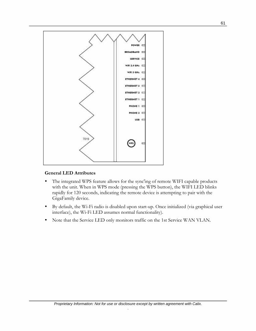
61
Proprietary Information: Not for use or disclosure except by written agreement with Calix. .
General LED Attributes The integrated WPS feature allows for the sync'ing of remote WIFI capable products
with the unit. When in WPS mode (pressing the WPS button), the WIFI LED blinks rapidly for 120 seconds, indicating the remote device is attempting to pair with the GigaFamily device.
By default, the Wi-Fi radio is disabled upon start-up. Once initialized (via graphical user interface), the Wi-Fi LED assumes normal functionality).
Note that the Service LED only monitors traffic on the 1st Service WAN VLAN.

62
Proprietary Information: Not for use or disclosure except by written agreement with Calix. .
LED States and Status
The LED's located on the face of GigaFamily products provide information on the status and current state of the device.
Note: Check mark indicates LED state and function are in effect. "X" mark indicates the feature is not available or not applicable.
Power LED (Green/Red/Amber) Software Controlled
LED State Function 801G 812G 813G 844G 854G 844E
Off Power is off. There is no power to the unit or the UPS battery is missing or failed and cannot provide back-up power.
Flashing Green Device is booting up. All hardware and software self tests are fully functional.
Solid Green In boot-up mode, device is powered on and
boot-up is complete.
Solid Red In boot-up mode, red during hardware boot-up test. Remains red if the hardware test fails.
Solid Amber In boot-up mode, turns amber during the
software image boot test. Remains amber if software test fails.
Flashing Amber Device is performing a local firmware upgrade. If successful, unit reboots. If unsuccessful, LED returns to solid green.
Solid Amber after Mechanical Reset
When the reset button is held in for more than 5 seconds, the device is ready to reset to factory default values.
Flashing Green/Amber
During a remote TR-069 upgrade, the Power LED blinks amber, then green in one second increments. Repeats until remote upgrade is complete.

63
Proprietary Information: Not for use or disclosure except by written agreement with Calix. .
Broadband LED (Green/Red/Amber) Software Controlled
LED State Function 801G 812G 813G 844G 854G 844E
Off WAN link down or no optical or Ethernet link detected
Solid Green Broadband physical connection is established.
Device has ranged and synchronized
Flashing Green (slow)
WAN link has been detected, carrier signal is present. Device in process of ranging and synchronizing to network. Note: Does not apply to 844E GigaCenter.
Solid Red
If carrier is not detected, Broadband LED turns solid red. Optical signal present but no sync due to bit errors, out of range, or no negotiate. Turns red after 2 minutes if no success above. Flashes green during initial 2-minute sync until pass or fail.

64
Proprietary Information: Not for use or disclosure except by written agreement with Calix. .
Service LED (Green/Red/Amber) Software Controlled
LED State Function 801G 812G 813G 844G 854G 844E
Off
Internet service has not been established. Physical connection may not be present or service may not be enabled.
Bridged Mode: No Ethernet port has been provisioned
RG Mode: No IP address received or PPPoE session authentication has occurred.
Solid Green
Internet service has been established. IP address or PPPoE session has been provisioned. If operating in Bridged mode, indicates that one Ethernet port has been provisioned
OMCI Layer-2 Bridged Mode: At least one Ethernet port has been provisioned
RG Mode (IPv4 or IPv6): Receive IP address or PPPoE session authenticated with credentials. If IPv4 and/or IPv6 is connected, LED remains solid.
Mixed Mode: RG mode conditions apply
Flashing Green (Slow)
IGD Layer-2 Bridged Mode: No ports configured for RG mode. WAP mode or all interfaces configured using EWI or TR-069 as transparent bridge.
No Hardware
Limit
Flashing Green (Activity)
RG Mode (IPv4 or IPv6): Internet service established, IP activity seen on connection between WAN-to-LAN or LAN-to-WAN.
Solid Red
Internet service attempted to establish connection in RG mode but failed to an an IP address or provisioned PPPoE session. Not applicable in Bridged Mode.
OMCI or IGD Layer-2 Bridged Mode: Does not apply.
RG Mode: Device attempted to become IP or PPPoE session (authentication failed)
Mixed Mode: RG mode conditions apply
Solid Amber Walled Garden: When in the walled garden state,
Internet LED supports the following: Solid Amber Activity blink of .2 seconds on and off during
LAN to WAN and WAN to LAN Activity. Walled Garden state initiates as follows: The modem is authenticated with the
[email protected] PPP username in PPPoE mode.
The CPE captive portal is enabled via ACS in all protocols.

65
Proprietary Information: Not for use or disclosure except by written agreement with Calix. .
2.4 GHz Wi-Fi LED (Green) Hardware Controlled
LED State Function 801G 812G 813G 844G 854G 844E
Off Radio is OFF or has not been enabled.
Solid Green Radio is ON but there are no clients
associated or no wireless activity. A client may be associated to the radio/SSID but may be idle.
Flashing Green (slow)
Radio is ON and has at least one client associated to it with wireless activity.
The flickering of the light is roughly synchronized to actual data traffic.
5.0 GHz Wi-Fi LED (Green) Hardware Controlled
LED State Function 801G 812G 813G 844G 854G 844E
Off Radio is OFF or has not been enabled.
Solid Green Radio is ON but there are no clients
associated or no wireless activity. A client may be associated to the radio/SSID but may be idle.
Flashing Green (slow)
Radio is ON and has at least one client associated to it with wireless activity.
The flickering of the light is roughly synchronized to actual data traffic.
Ethernet (1-4) LED (Green) Hardware Controlled
LED State Function 801G 812G 813G 844G 854G 844E
Off No Ethernet link established or device connected to port may not be powered.
Solid Green Device is connected to the associated port,
Ethernet link is up but no Ethernet traffic present.
Flashing Green (slow)
Activity seen from devices associated with the port.
Activity of the LED is roughly synchronized to actual ingress data traffic from device to port.

66
Proprietary Information: Not for use or disclosure except by written agreement with Calix. .
Phone (1-2) LED (Green/Red/Amber) Software Controlled
LED State Function 801G 812G 813G 844G 854G 844E Off Phone line is disabled, not provisioned or no
phone lines off-hook.
Solid Green The phone line is configured and on-hook. Line is provisioned and registered with the SIP server.
Flashing Green Phone line is off-hook, call is active. Flashing indicates active call.
Solid Red Voice registration with the network has failed.
No calls are possible until phone line has been registered and is in service.
USB LED (Green) Software Controlled
LED State Function 801G 812G 813G 844G 854G 844E Off The USB port is disabled or device connected
to port may not be powered.
Solid Green Powered device connected to the associated port, link is active but no Ethernet traffic present.
Flashing Green (slow)
Activity seen from devices associated with the port.
Activity of the LED should be synchronized to actual ingress data traffic from device to port.
WPS LED (Green/Red/Amber) Software Controlled
LED State Function 801G 812G 813G 844G 854G 844E Off WPS LED is off when Wireless Protected Setup
procedure is not active or is disabled.
Solid Green (3 minutes or until WPS button is pressed again)
The WPS procedure has been completed successfully, a device has been associated to an SSID
Flashing Green (slow)
The WPS procedure has been activated for Primary 2.4 and 5GHz SSID and may be in process of associating a device
Flashing Amber (slow)
The WPS procedure has been activated for IPTV 5GHz SSID and may be in process of associating a device
Solid Red (up to 2 minutes)
A non-security based error, such as failed to find any client or WPS procedure stopped.
Recommended user action is to press WPS button to start procedure again.
Flashing Red (Fast)
The WPS procedure has detected a session overlap.
Recommendation is to wait 2 minutes, then select WPS to re-attempt WPS procedure

67
Proprietary Information: Not for use or disclosure except by written agreement with Calix. .
Configuring Home Gateway Applications Home Gateway applications are provisioned in a similar fashion to Layer-2 GPON services:
Configuring the network uplinks Creating service-related profiles Configuring subscriber services.
However, you also need to define all of the key management aspects of a Home Gateway GigaCenter as well as the logical assignments of physical GE ports for the initial setup.
Note: The CMS management model is required to designate a specific RG configuration file instance to download on a per GigaCenter basis. The service provider can administer two different RG configuration files on the E7.
At the highest level, the required provisioning sequence is as follows:
Creating an RG Configuration File Scheduling RG Configuration Management Tasks in CMS Create required GPON profiles and a basic GigaCenter (ONT) template Build match lists and service tag action rules Build multi-cast video profiles Build Ethernet Bandwidth profiles Provision the GigaCenter Create Home Gateway services
The actual details of the provisioning of the Residential Gateway are covered in the E7 GPON Application Guide. Refer to Configuring Home Gateway Applications for complete provisioning information.
For convenience, the initial turn-up of the GigaCenter itself is covered in detail here.

68
Proprietary Information: Not for use or disclosure except by written agreement with Calix. .
Home Gateway Configuration via Local Access After installation and CMS provisioning of the GigaCenter using the default RG profile, a service technician on site with the GigaCenter can logon to the Home Gateway EWI using the Administer account to provision and activate services. The assumption is that the access model and services to be provisioned are easy to administer and do not require a download of a Service Defined RG configuration file. Many of the utilities and advanced features used to configure services are in the main subscriber EWI or reside within the service support pages.
Under this scenario the on-site service technician must be capable of manually entering and confirming the correct service access models. Once changes are made to the RG configuration, the technician has the option of using Utilities > Configuration Save to store a copy of the service profile either locally on the subscriber’s computer or remotely to a server.
For additional information on the Configuration Backup/Restore feature, refer to the Configuration Save topic in this guide.
This saved RG Configuration file can be used at a future date to locally or remotely restore the RSG to its initial installation configuration.
Note: Locally saved configurations (using Configuration Save), is specific to that RG device; it includes all of the default values for that RSG such as Administer Username and Password, SSID and WPA/WPA2 key. These RG specific attributes may not be applicable to other GigaCenter units at other locations.

69
Proprietary Information: Not for use or disclosure except by written agreement with Calix. .
Supported and Unsupported Use Cases The 844E incorporates the same wireless capabilities as the 844G and 854G GigaCenters. As such, the services and applications supported from a subscriber’s prospective are the same with carrier grade wireless, IPTV distribution using 5 GHz Wi-Fi, and high speed data services. With the initial launch of the GigaCenter platform, the Wi-Fi capabilities were greatly enhanced with support of concurrent 2.4 GHz and 5 GHz support and high speed applications over 5 GHz. Because many of the service specific use cases are the same, the use cases in this planning guide highlight some of the new applications supported by the 844E GigaCenter.
Supported Use Cases
844E Connected to Layer-2 ONT Residential IPTV Services
High Speed Internet WAN to LAN Support at 1 Gbps
IPTV over Wi-Fi with QoS RG with Routed Interfaces
Network Side Bandwidth Policy 844E Does not Allocate/Admin
Bandwidth
IPTV over Wi-Fi with QoS RG with Bridged Interfaces
HSI Services on Routed WAN IPTV MediaRoom Layer-3 Routed Interface
Ookla HSI LAN Speed Test IPTV Minerva Layer-2 Bridged Interface
Ookla HSI Wi-Fi Speed Test IPTV Innovative Layer-2 Bridged Interface
Residential Voice Services 844E as Video Access Point (VAP)
Concurrent Layer-2 IPTV and Routed HSI Services UPnP/DLNA for Media Sharing
Metaswitch, C15, and C20 SIP Softswitches
Concurrent Triple Play Voice, HSI, and IPTV Video
Unsupported Use Cases
Bandwidth Management and Shaping for HB and RG Services Layer-2 Business Services
Layer-2 Security (MACFF, IPSRV, DHCP Snoop, MAC Filtering) Open Access HSI and Voice
Service Interdiction Lifeline Voice with Battery Back-up
CMS Management 844E Connected to VDSL Modem or Cable Modem
Network Analytics Public, SBU, and Enterprise Wi-Fi PassPoint/HotSpot 2.0
UDP Speed Test MDU Applications and Wi-F

70
Proprietary Information: Not for use or disclosure except by written agreement with Calix. .

Proprietary Information: Not for use or disclosure except by written agreement with Calix. .
Appendix A
Appendix
Embedded Web Interface Field Definitions
GigaCenter Embedded Web Interface Status Menu (on page 74)
Sub-Menu Item Description
Connections (on page 75)
The Connections page provides network status/details for the GigaCenter network. The table below reflects the current state of the WAN, Local Internet, and the IP Gateway connections.
Devices (on page 77)
The devices table displays a list of devices currently connected to the Local Area Network. Devices can be edited from the Edit Device table.
Internet (on page 79)
Current Internet status of the Internet Service Provider is viewable. Basic connection status, ISP statistics, and IPv4/IPv6 Addressing parameters are available.
Ethernet (on page 81)
The table reflects the Ethernet port connection status including connection speeds and current packet statistics.
Wireless (on page 82) The table displays a summary of the settings for each wireless network (by device).
NAT (on page 84) This dynamic table reflects the current state of the Network Address Translation (NAT). As IP addresses are resolved against the NAT table, contents of this screen are updated in real time.
Routing (on page 85) The table displays the current routing assignments for Internet traffic on the network.
Security (on page 86) The table displays all modified security settings from the factory default values.

72
Proprietary Information: Not for use or disclosure except by written agreement with Calix. .
Quick Start Menu (on page 86)
Sub-Menu Item Description
Connect to Internet (on page 87)
Gateway device connection settings are provisioned here.
Configure Wireless Network (on page 89)
Configure Wireless Network is used to enable or disable connections between this gateway device and other wireless devices. Use this screen to configured your SSID and password for the wireless network.
Set Time Zone (on page 90) Set Time Zone is used to display this gateway device's time settings.
Wireless Menu (on page 91)
Sub-Menu Item Description
Radio Setup (on page 93)
For both the 2.4 GHz and 5 GHz radio, settings for enabling the radio, choosing the wireless mode, channel bandwidth, channel selection method, channel power level, and wireless multicast forwarding options are provided. For the 5 GHz radio, dynamic frequency selection can also be enabled or disabled.
SSID Setup (on page 96) Identifies the device within the network so that other devices can connect to it.
Security (on page 98) Wireless traffic can be secured by enabling customer security keys or pass-phrases.
MAC Authentication (on page 99)
Wireless networks can be further secured by using MAC addresses to identify specific wireless devices.
Wi-Fi Multimedia (WMM) (on page 100)
This Quality of Service (QoS) feature prioritizes traffic on your network.
Advanced Radio Set-up (on page 101)
Various countries will allow or block certain Wi-Fi channels and as such, you can specify what country the radio is being deployed in. In addition, these countries may have varying Wi-Fi signal power levels which are also selectable by country.
WPS (on page 101)
WPS provides a secure way to establish a wireless network by sharing the wireless key between the device and wireless client.

73
Proprietary Information: Not for use or disclosure except by written agreement with Calix. .
Utilities Menu (on page 102)
Sub-Menu Item Description
Configuration Save (on page 105)
Configuration Backup is used to save the gateway device configuration information to a file on your PC. Configuration Restore reloads the file from your PC to restore your gateway device back to the same settings as when the backup file was last saved.
Restore Defaults (on page 108) Select the restore button to restore the gateway device to the default settings
Reboot (on page 108) Select the Reboot button to reboot the gateway device.
Web Activity Log (on page 109)
Web Activity Log displays a list of the most recently accessed websites. This table displays URL's accessed by the CPE on the LAN side of the RSG.
Ping Test (on page 110)
Test your internet connectivity to a specific host using the ping test below. Results of completed ping tests are displayed with detailed statistics. Tests can be run against IPv4 or IPv6 formatted addresses.
Traceroute (on page 113)
Traceroute is used to determine the route taken by packets across a network. Each test reports the round trip times for 3 ICMP packets. Each response shows the maximum number of hops displayed in the first column. The test repeats until the host is reached or the maximum hop count of 30 is reached. The times for each ICMP packet are displayed in the table. An asterisk (*) in a field means that no-response was received for the ICMP packet request.
System Log (on page 114) The system log provides an accounting of significant gateway device events.
Firewall Log (on page 115)
The Firewall Log page provides a table of the most recently dropped packets by the firewall.
Advanced Menu (on page 117)
Sub-Menu Item Description
Scheduling and Blocking (on page 117)
Scheduling and Blocking allows for the configuration of network access, service blocking, and website blocking.
IP Addressing (on page 125)
IP Addressing settings allow for the configuration of WAN, DHCP, and DNS settings across the network.
Static Routing (on page 133) Routing settings allow for the configuration of static routing across the network.
Quality of Service (on page 134)
Quality of Service settings allow for the configuration of QoS prioritization rules across the network.
Security (on page 136) The Calix GigaCenter incorporates various features that ensure overall network security.
Remote Management (on page 149)
Remote Management settings allow for the configuration of a secure connection to the GigaCenter network from a remote location.

74
Proprietary Information: Not for use or disclosure except by written agreement with Calix. .
Status Menu The Status Menu provides information on the status of GigaFamily device network settings.
Status Menu Overview The Status menu provides real time information on all network elements.
Connections (on page 75) - Provides information on network connectivity status as well as IP Gateway state and status.
Devices (on page 77) - Provides a list of active or inactive devices residing on the network. Also provides the option of editing specific device names and changing the icon representing the device.
Internet (on page 79) - Provides information on the ISP connection, protocols used, traffic statistics, and IP Addressing information for devices and DNS service locations.
Ethernet (on page 81) - Displays the devices Ethernet ports and provides connection status with packet statistics.
Wireless (on page 82) - Provides state and status of any of four possible Wi-Fi networks (selectable) provisioned on the unit.
NAT (on page 84) - Provides a dynamic display of the Network Address Translation table including Source/Destination IP info, protocol used, and source/destination port.
Routing (on page 85) - Provides a table of IPv4 routing assignments including Destination IP, Network Mask, and Gateway IP address information.
Security (on page 86) - Provides a table of security features that have customized "rules" applied that deviate from the default behavior

75
Proprietary Information: Not for use or disclosure except by written agreement with Calix. .
Connections The Connections page provides network status/details for the GigaCenter network. The table below reflects the current state of the WAN, Local Internet, and the IPv4/IPv6 Gateway connections.

76
Proprietary Information: Not for use or disclosure except by written agreement with Calix. .
Status - Connection - Connection Field Definitions
Label Definition Field Type
Editable? Allowable Values/Defaults
Wide Area Network (WAN)
Connection status of the GigaCenter to the WAN Info Only N Connected‡, Not Connected
IPv4 Internet Access Displays the current connection state of the GigaCenter Info Only N Unconfigured, Connecting, Connected,
Disconnecting, Disconnected, Blank‡
IPv6 Internet Access Displays the current connection state of the GigaCenter Info Only N Unconfigured, Connecting, Connected,
Disconnecting, Disconnected, Blank‡
To edit the above settings, go to Advanced > IP Addressing > WAN Settings
Status - Connection - Gateway Field Definitions
Software Version Version of operating system software currently loaded on the GigaCenter Info Only N Firmware Release Number
Model Number Calix GigaCenter Model Number Info Only N Model Number
Serial Number Unique FSAN Serial Number Info Only N FSAN Serial Number. Begins with CXNK followed by 8 alphanumeric digits
WAN MAC Address WAN's Medial Access Code (MAC) Address Info Only N MAC Address (xx:xx:xx:xx:xx:xx)
Downstream Rate Current rate the GigaCenter is receiving data from the WAN Info Only N Numeric Value in bits/second
Upstream Rate Current rate the GigaCenter is sending data to the WAN Info Only N Numeric Value in bits/second
PPP User Name Point-to-Point Protocol User Name Info Only N URL of the PPPoE User Name. Value set at Quick Start > Connect to Internet > PPPoE Set-up.
ISP Protocol Protocol used to connect with the ISP Info Only N DHCP, PPPoE, or Static. Value established at Quick Start > Connect to Internet.
Device IP Address IP address assigned to the GigaCenter Info Only N dot delimited, xx.xx.xx.xx. value established at Quick Start > Connect to Internet.
IPv4 DNS Address # 1 and IPv4 DNS Address # 2
The Domain Name Server (DNS) Addresses #1 and #2 are the IPv4 IP addresses of the primary and secondary servers that provide the URL to IP address translation for a specific site on the Internet. When a URL is entered into the address bar of a browser, the designated DNS translates the domain to an IP address to find the site on the Internet.
Info Only N
dot delimited, xx.xx.xx.xx. Can be automatic or static value. Value established at Quick Start > Connect to Internet.
IPv6 IP Address IP address assigned to the GigaCenter Info Only N dot delimited, xx.xx.xx.xx. Value established at Quick Start > Connect to Internet.
IPv6 DNS Address # 1 and IPv6 DNS Address # 2
The Domain Name Server (DNS) Addresses #1 and #2 are the IPv6 IP addresses of the primary and secondary servers that provide the URL to IP address translation for a specific site on the Internet. When a URL is entered into the address bar of a browser, the designated DNS translates the domain to an IP address to find the site on the Internet.
Info Only N
colons-hexadecimal notation. Can be automatic or static value. Value established at Quick Start > Connect to Internet.
To edit the above settings, go to Advanced > IP Addressing > WAN Settings ‡ = Default Value

77
Proprietary Information: Not for use or disclosure except by written agreement with Calix. .
Devices The table below displays a list of devices currently connected to the Local Area Network. Devices can be edited from the Edit Device table.
Status - Devices Field Definitions
Label Definition Field Type Editable? Allowable Values/Defaults Show inactive devices
Selecting this box displays or hides the list of inactive devices connected to the GigaFamily device.
Check Box Yes N/A - For Inactive devices, text is displayed as "grayed out" if check box is selected.
Icon Graphical depiction of the device connected to the device.
Info Only To edit an icon, see section below.
Available icons include: Camera, Cell Phone, Computer, Gaming Console, iPhone, IPTV STB, Phone, Printer, PS-3, Router, Satellite Receiver, Server, Video Camera, Wii, X-Box 360.
Device Name assigned to device connected to the device
Info Only To edit a device name, see section
below.
Alphanumeric String - 16 characters maximum
IP Address IP address of the device connected to the device
Info Only No Auto-populate. When device connects and is recognized, IP address is displayed in this field.
MAC Address MAC address of the device connected to the device
Info Only No Auto-populate. When device connects and is recognized, MAC address is displayed in this field.
Connection Type Type of connection between the GigaFamily device and this attached device.
Info Only No Auto-populate. Wi-Fi or Ethernet.

78
Proprietary Information: Not for use or disclosure except by written agreement with Calix. .
Status - Edit Device Field Definitions
Select the LAN device
Choose the LAN device connected to the device from the pull down menu
Drop-down List
No, list reflects
connected device’s
name (name can be
changed in "Enter the
new device name" field
below)
The device’s IP Address is the default device name.
Enter the new device name
Change the selected LAN device's name Alpha-text Box
Yes Alpha-numeric string Note: Spaces are not allowed in this string.
Select a device icon Choose the graphical element to be displayed that represents this device
Drop-down List
Yes Available icons include: Camera, Cell Phone, Computer, Gaming Console, iPhone, IPTV STB, Phone, Printer, PS-3, Router, Satellite Receiver, Server, Video Camera, Wii, X-Box 360.
NOTE: Static Devices are not displayed in this table.

79
Proprietary Information: Not for use or disclosure except by written agreement with Calix. .
Internet Current Internet status of the Internet Service Provider is viewable. Basic connection status, ISP statistics, and IPv4/IPv6 Addressing parameters are available.

80
Proprietary Information: Not for use or disclosure except by written agreement with Calix. .
Status - Internet - Internet Status Field Definitions Label Definition Field
Type Editable? Allowable Values/Defaults
IPv4 Connection Status of the IPv4 Internet Connection Info Only No Unconfigured, Connecting, Connected, Disconnecting, Disconnected, Blank‡
IPv6 Connection Status of the IPv6 Internet Connection Info Only No Unconfigured, Connecting, Connected, Disconnecting, Disconnected, Blank‡
Status - Internet - Internet Settings Field Definitions WAN Protocol WAN protocol type Info Only No IP Routed
Device Uptime Elapsed time since last loss of connection of the device Info Only No
Days/Hours/Minutes/Seconds format Example: 6D 17H 26M 15S
MTU Size
The Maximum Transmission Unit size reflects the largest number of bytes able to be carried in a protocol’s data transmission packet including header information
Info Only No Maximum number of bytes in a packet including header info. Default: 1500 bytes
MSS Size
The Maximum Segment Size reflects the largest number of bytes able to be carried in a protocol’s data transmission packet not including header information
Info Only No Maximum number of bytes in a packet not including header info. Default: 1460 bytes
TCP Connection
Transmission Control Protocol connection manages a data stream across the Internet ensuring reliable delivery
Info Only No Numeric Default: 22
RWIN Size
RWIN (TCP Receive Window) size is the amount of data that a computer can accept without acknowledging the sender
Info Only No Numeric Default: 122880 bytes
Status - Internet - IPv4 Addressing Field Definitions Device IPv4 Address IPv4 address for the device Info Only No Dot delimited, xx.xx.xx.xx
Device IPv4 Subnet Mask
Internet Protocol v4 Subnet Mask is used to split and confine traffic to one network. A subnet mask keeps all local network traffic local and only routes Internet traffic to the Internet preserving network resources
Info Only No Dot delimited, xx.xx.xx.xx Default: 255.255.255.0
DNS Address #1 The Domain Name Server (DNS) Addresses #1 and #2 are the IP addresses of the primary and secondary servers that provide the URL to IP address translation for a specific site on the Internet. When a URL is entered into the address bar of a browser, the designated DNS translates the domain to an IP address to find the site on the Internet
Info Only No Dot delimited, xx.xx.xx.xx
DNS Address #2 Info Only No Dot delimited, xx.xx.xx.xx
Remote Gateway Address
Remote Gateway IP Address for the device
Info Only No Dot delimited, xx.xx.xx.xx
IPv4 Packets Sent Number of IPv4 packets sent by the device
Info Only No Numeric
IPv4 Packets Received Number of IPv4 packets received by the device
Info Only No Numeric
Link Uptime Elapsed time since last loss of connection to the gateway of the device
Info Only No Days/Hours/Minutes/Seconds format Example: 6D 17H 26M 15S

81
Proprietary Information: Not for use or disclosure except by written agreement with Calix. .
Status - Internet - IPv6 Addressing Field Definitions
Device IPv6 Address IPv6 address for the device Info Only No colon-hexadecimal notation
DNS Address # 1 The Domain Name Server (DNS) Addresses #1 and #2 are the IP addresses of the primary and secondary servers that provide the URL to IP address translation for a specific site on the Internet. When a URL is entered into the address bar of a browser, the designated DNS translates the domain to an IP address to find the site on the Internet
Info Only No colon-hexadecimal notation
DNS Address # 2
Info Only No colon-hexadecimal notation
IPv6 Gateway Address IPv6 Gateway Address for this device Info Only No Numeric
IPv6 Packets Sent Number of IPv6 packets sent by the device Info Only No Numeric
IPv6 Packets Received Number of IPv6 packets received by the device Info Only No Numeric
Ethernet The table below reflects the Ethernet port connection status including connection speeds and current packet statistics.

82
Proprietary Information: Not for use or disclosure except by written agreement with Calix. .
Status - Ethernet Field Definitions Label Definition Field
Type Editable? Allowable Values/Defaults
Port Ethernet ports 1 through 4 as labeled on the GigaFamily device
Info Only No 1 through 4
Connection Speed 10/100/1000 BaseT Ethernet connection speed
Info Only No Auto-sensing and Auto-negotiating speed values: 10M, 100M, 1000M, Disconnected‡
IPv4 & IPv6 Packets Sent
Packets sent to each device connected to a GigaFamily Ethernet Port
Info Only No Number of packets sent - Numeric
IPv4 & IPv6 Packets Received
Packets received from each device connected to a GigaFamily Ethernet Port
Info Only No Number of packets received - Numeric
Wireless The table below displays a summary of the settings for each wireless network (by device).

83
Proprietary Information: Not for use or disclosure except by written agreement with Calix. .
Status - Wireless Network Status Field Definitions
Label Definition Field Type Editable? Allowable Values/Defaults Network Name (SSID) Pull down list of wireless network names
(SSID) Drop-down
List Yes List of Network Names created in the
system. Up to 4 networks are allowed. Network State State of the selected wireless network Info Only No Enabled‡/Disabled Network Name Broadcast
Wireless broadcast of wireless network name
Info Only No Enabled‡/Disabled
Wireless Radio Wireless Radio State Info Only No On‡/Off Wireless Mode List of wireless modes supported
Note: If viewing 5 GHz radio, 802.11ac mode is also available.
Info Only No 802.11b, 802.11g, and 802.11n
Frequency Wireless radio broadcast frequency Info Only No 2.4 GHz, 5 GHz Default: Dependent on which radio this specific SSID is set to.
Operating Channel Number of active wireless radio broadcast channels
Info Only No Number of active channels
Channel Mode Defines whether the current channel displayed was dynamically assigned (Auto Select) or manually selected (Manual)
Info Only No Auto‡ or Manual
Wireless Security State of wireless network security Info Only No Enabled‡/Disabled See Wireless > WPS (on page 101)
Wireless Security Type
Type of wireless network security being used
Info Only No WPA - WPA2-Personal, WPA-Personal, WPA2-Personal, WEP See Wireless > Security (on page 101)
MAC Authentication Filter
State of the MAC authentication filter Info Only No Enabled/Disabled‡
Wi-Fi Protected Setup (WPS)
State of the WPS feature Info Only No Enabled/Disabled‡
Wi-Fi Protected Setup Type
How is Wi-Fi Protected Setup mode launched (method employed)?
Info Only No Push Button Control (PBC)‡
Wi-Fi Multimedia (WMM) Power Save
State of the WMM Power Save mode Info Only No Enabled‡/Disabled See Wireless > Security > WMM (on page 100)
IPv4 & IPv6 Wireless Packets Sent
Number of wireless packets sent from the GigaFamily device.
Info Only No Numeric - Number of packets sent
IPv4 & IPv6 Wireless Packets Received
Number of wireless packets received from the GigaFamily device.
Info Only No Numeric - Number of packets received
Connected Devices Label Definition Field Type Editable? Allowable Values/Defaults
Icon Graphic depiction of the connected device Info Only No N/A
Device Device Type Info Only No N/A
IP Address IP Address of the connected device Info Only No IPv4 dot delimited or IPv6 colon-hexadecimal delimited IP Address
Mac Address MAC Address of the connected device Info Only No NA
Mode Indicates the wireless protocol being used on this device Info Only No 802.11b, 802.11n, 802.11g, 802.11ac
Status Indicates signal strength of connected device Info Only No In dbm
DS Data Rate (Mbps) Indicates the downstream data rate of the connected device Info Only No Numeric in Mbps
US Data Rate (Mbps) Indicates the upstream data rate of the connected device Info Only No Numeric in Mbps
Type Network protocol being used Info Only No b, g, n, ac

84
Proprietary Information: Not for use or disclosure except by written agreement with Calix. .
NAT (Network Address Translation) This dynamic table reflects the current state of the Network Address Translation (NAT). As IP addresses are resolved against the NAT table, contents of this screen are updated in real time.
Status - NAT - Network Address Translation (NAT) Field Definitions
Label Definition Field Type Editable? Allowable Values/Defaults
Protocol Type of protocol used to manage Internet data streams on this device
Info Only No Alphanumeric protocol name. TCP, UDP
Timeout Number of seconds remaining for this table entry.
Info Only No 1-120 seconds Note: Entry of 431999 indicates an entry that has just expired.
Source IP Data stream source device IP address Info Only No Dot delimited, xx.xx.xx.xx
Source Port Data stream source device port number Info Only No Numeric (1-65535)
Destination IP IP Address of the GigaFamily device Info Only No Dot delimited, xx.xx.xx.xx
Destination Port Destination Port for the GigaFamily device
Info Only No Numeric port Number, 5 digit maximum

85
Proprietary Information: Not for use or disclosure except by written agreement with Calix. .
Routing The table below displays the current routing assignments for Internet traffic on the network.
Status - Routing - IPv4 Routing Field Definitions
Label Definition Field Type Editable? Allowable Values/Defaults
Valid Valid IPv4 routing assignments Info Only No YES/NO
Destination Data streams WAN Destination IP Address
Info Only No Dot delimited, xx.xx.xx.xx
Netmask GigaFamily device Lan IP network mask Info Only No Dot delimited, xx.xx.xx.xx
Gateway GigaFamily device Gateway IP Address Info Only No Dot delimited, xx.xx.xx.xx
Note: GigaFamily devices do not currently support IPv6 routing.

86
Proprietary Information: Not for use or disclosure except by written agreement with Calix. .
Security The table below displays all modified security settings from the factory default values.
Status - Security - Security Field Definitions
Label Definition Field Type
Editable? Allowable Values/Defaults
Security Feature WAN and Lan security feature descriptions
Info Only No Applications, DMZ Hosting, Firewall Settings, NAT, UpNp
LAN IP The IP address of the LAN interface Info Only No Dot delimited, xx.xx.xx.xx. If no LAN is configured, undefined is displayed.
Applied Rule Description of applied rule when deviating from default security settings
Info Only No Displays currently assigned rule for security features shown above

87
Proprietary Information: Not for use or disclosure except by written agreement with Calix. .
Quick Start Menu Residential Service Gateway turn-up settings and parameters are contained in this menu category.
Quick Start Menu Overview The Quick Start menu provides initial internet and wireless network connection options as well as set-up for the network clock.
Connect to Internet (on page 87) - Provides provisioning options for connecting to the Internet including connection type, configuration of DHCP or Static IP addressing versus Point to Point over Ethernet connections, and identification of the Domain Name Server service.
Configure Wireless Network (on page 89) - Provides facilities for configuring any 1 of 4 possible Wi-Fi networks provided by the GigaFamily device. Wi-Fi can be enabled or disabled, given a network name and password for access. This Wi-Fi network is initialized via Wireless Protected Set-up (WPS/WPA, and the like). Both 2.4 GHz and 5.0 GHz radios can be enabled simultaneously.
Set Time Zone (on page 90) - To ensure network elements remain in synchronization, the time zone must be set. A facility for adjusting to Daylight Savings time is also provided.
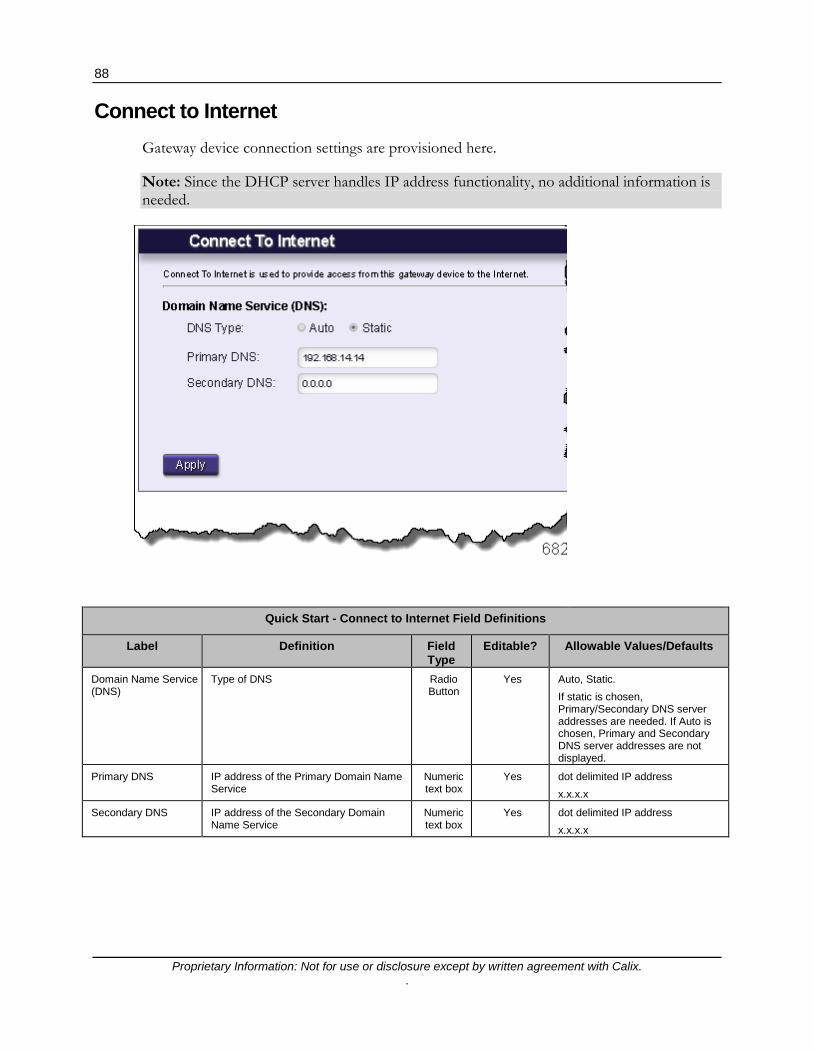
88
Proprietary Information: Not for use or disclosure except by written agreement with Calix. .
Connect to Internet Gateway device connection settings are provisioned here.
Note: Since the DHCP server handles IP address functionality, no additional information is needed.
Quick Start - Connect to Internet Field Definitions
Label Definition Field Type
Editable? Allowable Values/Defaults
Domain Name Service (DNS)
Type of DNS Radio Button
Yes Auto, Static. If static is chosen, Primary/Secondary DNS server addresses are needed. If Auto is chosen, Primary and Secondary DNS server addresses are not displayed.
Primary DNS IP address of the Primary Domain Name Service
Numeric text box
Yes dot delimited IP address x.x.x.x
Secondary DNS IP address of the Secondary Domain Name Service
Numeric text box
Yes dot delimited IP address x.x.x.x

89
Proprietary Information: Not for use or disclosure except by written agreement with Calix. .
Configure Wireless Network Configure Wireless Network is used to enable or disable connections between this gateway device and other wireless devices. Use this screen to configure your SSID and password for the wireless network.

90
Proprietary Information: Not for use or disclosure except by written agreement with Calix. .
Quick Start - Configure Wireless Network Field Definitions
Label Definition Field Type Editable? Allowable Values/Defaults
Wireless Enables or disables the wireless network from the GigaFamily device to all other wireless devices
Radio Button Yes On‡ or Off
Network Name Wireless network name. This is typically the devices FSAN Serial Number.
Alpha-text Box Yes Alphanumeric - 32 characters maximum
WPA/WPA2 Password
Wireless network security key Alpha-text Box No Alphanumeric - 63 characters maximum* Default: Field is auto-populated with password configured at factory. This password also appears on the self-adhesive label. Note: To change to a Custom Security Key, navigate to Wireless > SSID Setup > Security > Security Key/Passphrase and then enter a Custom Security Key. * Only the first 27 characters of the string are displayed in this window. To avoid confusion, keep security keys shorter than 27 characters.
Wireless Access Point (Bridge Mode)*
Enable or disable the WAP/STUN feature set for subtending a GigaFamily device behind an existing residential gateway.
Radio Button Yes Enable, Disable‡
Apply Button for applying changes to Wireless Network Settings
Action Button No Apply changes to above settings
* - When configured as a bridged Wireless Access Point (WAP), the web interface of the WAP will no longer be reachable via the current IP address. To maintain access to the EWI, retrieve the new IP address from the upstream home router.
Wireless Protected Setup Connect Wireless Protected Setup (WPS)
is an easy and secure way to establish a wireless network connection between the GigaFamily device and another wireless device by sharing the wireless password between the devices. Press the Connect button in the menu and then press the WPS button on the other wireless device. Conversely, pressing the WPS button on the GigaCenter achieves the same result.
Action Button No Ready the unit for connection to other wireless devices (Ready state).

91
Proprietary Information: Not for use or disclosure except by written agreement with Calix. .
Set Time Zone Set Time Zone is used to display this gateway device's time settings.
The displayed timezone setting for the GigaFamily device is controlled by the NTP server setting that is pre-provisioned in the configuration file.
Quick Start - Set Time Zone Field Definitions
Label Definition Field Type Editable? Allowable Values/Defaults
Timezone Displays time zone based on location of the unit. Choose the appropriate timezone from the drop-down list provided. Important: Timezone displayed is in UTC Time. Note: In a GPON environment, Timing is derived from the OLT's timing source and will over-ride any settings made here.
Drop-down List
View Only Default: Pacific Time (US and Canada)
Automatically adjust clock for Daylight Saving Time
Determine whether the NTP Server time makes adjustment for Daylight Saving Time.
Check box View Only Default: Unchecked (No adjustment for daylight savings time)

92
Proprietary Information: Not for use or disclosure except by written agreement with Calix. .
Wireless Menu Under the Wireless menu, Wi-Fi, security, WPS, and MAC authentication parameters are provisioned.
Note: For purposes of this guide, definitions for both 2.4 GHz and 5.0 GHz wireless radios are combined and shown as one screen. Differences between the two protocols are noted.

93
Proprietary Information: Not for use or disclosure except by written agreement with Calix. .
Wireless Menu Overview The Wireless menu provides set-up for the wireless radio, SSID, security, authentication, and Wi-Fi Multimedia prioritization. Set-up is available for the 2.4 GHz and 5.0 GHz frequency bands independently.
Radio Setup (on page 93) - Includes option for enabling or disabling the Wi-Fi "radio". Options are available for setting frequency, channel, channel bandwidth, power level, and 802.11 wireless mode.
SSID Setup (on page 96) - Allows for enabling additional SSID's for the wireless network. Configure the SSID for unique subnets or defined start URL's. The device supports one default SSID (printed on the units label that is shipped with the product), and three optional SSID settings. The default SSID is broadcast when the gateway is powered on for the first time.
Security (on page 98) - Wireless Security allows for configuration of a unique Wireless Equivalent Privacy (WEP) key or Wi-Fi Protected Access (WPA and WAP2) security key/pass phrase. Wireless security can also be disabled.
MAC Authentication (on page 99) - Wireless MAC Authentication limits wireless network access to devices based on their MAC addresses. For a gateway to access a network with wireless MAC authentication, the MAC address of the gateway must be known by the wireless router.
WMM (on page 100) - Wireless Multimedia (WMM) provides Quality of Service (QoS) on the wireless network by prioritizing traffic depending on the traffic type. Applies to the 2.4 GHz frequency only
Advanced Radio Set-up (on page 101) - Wireless services based on country specific requirements can be selected.
WPS (on page 101) - Wi-Fi Protected Setup (WPS) provides secure connections to wireless networks. When enabled on the router and end device, network security settings are shared. Once set-up is complete, only authenticated devices are available on the network.

94
Proprietary Information: Not for use or disclosure except by written agreement with Calix. .
Radio Setup Radio Setup provides the ability to customize the wireless radio settings. Both 2.4 GHz and 5.0 GHz radios can be configured separately.
Radio Setup - 2.4 GHz
6838a Radio Setup - 5 GHz

95
Proprietary Information: Not for use or disclosure except by written agreement with Calix. .
2.4 and 5.0 GHz Wireless - Radio Setup Field Definitions
Label Definition Field Type Editable? Allowable Values/Defaults
Wireless Radio Enable or Disable the internal wireless radio of the RSG
Radio Button Yes ON‡ or OFF
Wireless Mode
Used to select the wireless protocol standard. Note: When provisioning the 5 GHz radio, choosing 802.11ac allows both 802.11ac and 802.11n capable devices to communicate to this radio.
Drop-down List Yes
802.11b* 802.11n* 802.11g* 802.11ac (applies to 5 GHz radio only) * - Applies to 2.4 GHz radio only‡. Can be configured to support a single protocol and any combination of the three.
Wireless Bandwidth
Used to set the wireless network bandwidth in the 5 GHz frequency range. Note: For the 2.4 GHz frequency, only 20 MHz service is available.
Drop-down List Yes 20 ‡ or 40 MHz
Wireless Channel Used to select the wireless network channel. In Auto mode, system selects best available channel.
Drop-down List Yes Channels 1 through 13 or Auto ‡
Wireless Power Level
Used to select the power level of the wireless radio. Calix recommends keeping the power level set to 100% under most circumstances.
Drop-down List Yes Percentage from 100% ‡ to 10% in 10%
increments
Wireless Multicast Forwarding (Applies to 2.4 GHz radio only)
Used to distribute multicast IP signals to multiple wireless devices. Check Box Yes
Checked (allow forwarding) ‡ When checked, multicast traffic received at the gateway is forwarded to all associated wireless clients Not Checked (block forwarding)
Airtime Fairness (Applies to 2.4 GHz radio only)
Air Time Fairness allocates equal time to each device on the network, regardless of their data transfer speeds. This fairness quotient may encourage subscribers to update older Wi-Fi clients since they will tend to receive insufficient air time when compared to newer, faster models.
Check Box Yes
Checked - Airtime Fairness in effect. Not Checked - All devices receive same amount of airtime equally (based on device specifications).
Frame Burst (Applies to 2.4 GHz radio only)
Enhances Wi-Fi transmissions primarily pertaining to transmission of 802.11n clients.
Check Box Yes Checked‡ Unchecked
DFS Enable (Applies to 5 GHz radio only)
On the 5 GHz band only, dynamic selection of frequencies in the 5.25-5.35 and 5.47-5.725 GHz ranges is supported. Enable or disable Dynamic Frequency Selection (DFS) here.
Check Box Yes Enable‡ or Disable
MU-MIMO (Applies to 5 GHz radio only)
Enable or disable Multi-User, Multi-Input Multi-Output mode (MU-MIMO). Increases throughput to two or more MU-MIMO capable devices.
Radio Button Yes Enabled, Disabled‡

96
Proprietary Information: Not for use or disclosure except by written agreement with Calix. .
PMF (Applies to 5 GHz radio only)
Enable/disable Protected Management Frames (PMF) for added security at the packet level. Protects Wi-Fi networks from potential eavesdropping. Note: May not be compatible with all Wi-Fi clients.
Radio Button Yes Enabled, Disabled‡
Apply Button used to apply all settings above Action Button No Apply and save changes
SSID Setup Service Set Identifier (SSID) is used to identify this gateway device for connection to other wireless devices. The SSID may be broadcast to publish its value to aid in connecting this device to other wireless devices or it may be hidden to discourage unauthorized access. The factory-defined SSID values may be redefined to a user-specified name.

97
Proprietary Information: Not for use or disclosure except by written agreement with Calix. .
Wireless - Service Set Identifier (SSID) Field Definitions
Label Definition Field Type Editable? Allowable Values/Defaults
SSID (Network Name) The name of the GigaFamily device (needed for identifying the unit when connecting to other wireless devices)
Drop-down List
Yes Alphanumeric Default: SSID on product label
SSID State Enable or Disable any non-primary SSID (stop/start BSS services). When disabled, the radio will not send beacon frames for this BSS and therefore STAs will not associate. Note: Primary SSID's cannot be disabled.
Checkbox Yes Enable, Disable ‡
Broadcast SSID Allows or restricts the wireless broadcast of the SSID (device network name) so networked and non-networked wireless devices are aware of the wireless network
Radio Button
Yes Enabled ‡ or Disabled
Rename SSID Rename the selected SSID (Network Name). Note: SSID names cannot be changed with the radio disabled.
Alpha-text Box
Yes Alphanumeric - 32 characters Default: Initially populated with SSID Network Name
Forward traffic from clients to WAN Interface only
Split Horizon Feature. This feature allows for the forwarding of all received traffic to the WAN based on specific SSID. When enabled, provides isolation between all end user devices and forces incoming frames up the WAN interface only. Prevents traffic passing between BSS's in the same bridge. This feature introduce as part of Community Wi-Fi enhancements.
Checkbox Yes Checked, Unchecked ‡
Allow guest network clients to communicate with each other
Intra-SSID isolation - controls whether STAs associated with the same SSID can communicate with one another. This feature displayed only for Guest SSID's.
Checkbox Yes Checked, Unchecked ‡
Isolate SSID within a network by creating a separate subnet
Inter-SSID isolation. Isolating "guest Wi-Fi devices" from the subscribers primary in-home network by assigning guest Wi-Fi devices to their own subnet. When chosen, Gateway and IP Address range fields are displayed in order to isolate Inter-SSID's.
Checkbox Yes Checked, Unchecked ‡
IP Addressing Values Ability to hard code specific Gateway, IP Address, and Subnet Mask values for isolating SSID's to their own subnet.
Checkbox Yes Checked, Unchecked‡

98
Proprietary Information: Not for use or disclosure except by written agreement with Calix. .
Wireless Security Secure your wireless traffic from security threats since wireless traffic transmits unprotected.
Wireless - Security Field Definitions
Label Definition Field Type Editable? Allowable Values/Defaults
SSID (Network Name)
A list of the SSID names for the wireless network
Drop-down List
Yes Listed names Default: SSID from the product label
Security Type A list of security types and options. WPA-WPA2-Personal and WEP types require different types of "Encryption" and "Authentication"
Drop-down List
Yes Listed security types: WPA-WPA2-Personal ‡, WEP, Security Off
Encryption Type A list of encryption types and options Drop-down List
Yes AES ‡, TKIP, or Both
Security Key/Passphrase
Security key/passphrase used for WPA-WPA2 secured network type (from above)
Radio Button
Yes Alphanumerical string, 63 characters max. Default: Security Key/Passphrase listed on product label
Security key/passphrase used for WEP secured network type (from above)
Radio Button for each SSID with Alpha-text Box for changing
security key
Yes Numeric hexadecimal or decimal string (12 characters maximum for 128 bit security, 10 characters maximum for 64 bit security) Default: 1234567890
Apply Button used to apply above settings Action Button
Yes Apply and save changes

99
Proprietary Information: Not for use or disclosure except by written agreement with Calix. .
MAC Authentication Limit access to your GigaFamily device by using the MAC address of specific wireless devices. A device list is also provided. With MAC Authentication enabled, options exist for excluding (Denied) or allowing (Allowed) specific MAC addresses within your wireless network.
Wireless - MAC Authentication Field Definitions
Label Definition Field Type Editable? Allowable Values/Defaults
SSID (Network Name)
A list of up to four SSIDs (Network Names) Drop-down List
Yes Up to 4 network names are displayed Default: SSID name from the product label
MAC Authentication State
MAC Authentication limits network access by using the MAC address of specific wireless device as a key for network access
Radio Button
Yes Enable or Disable Default: Enabled

100
Proprietary Information: Not for use or disclosure except by written agreement with Calix. .
MAC Authentication Display Table
Icon Displays the icon for the device type's MAC address that is enabled or denied.
Display Only No N/A
Device Device Name Display Only No N/A
IP Address IP Address of the device that has MAC Authentication definitions.
Display Only No N/A
MAC Address MAC address of this device Display Only No N/A
Connection Type How is this device connected to the network?
Display Only No Ethernet, Wi-Fi
Denied Displays the current status of the MAC Authentication. If in Denied or Allowed, displays Yes or No for each status type.
Display Only No
N/A
Apply Applies changes to MAC Authentication Action Button Yes Click to Apply
WMM (Wi-Fi Multimedia) WMM is a Quality of Service feature that prioritizes traffic on your wireless network.
Note: Applies to 2.4 GHz radio only.
Wireless - WWM Field Definitions
Label Definition Field Type Editable? Allowable Values/Defaults
WMM state Enables or disables Wi-Fi Multimedia functionality
Radio button
Yes Enabled ‡ or Disabled
Power Save Enables or disables Power Save functionality. The power save feature allows client devices to conserve power by going to sleep while the access point buffers downlinked frames. The power save function determines when to wake-up the client to receive packets without affecting QoS.
Radio button
Yes Enabled ‡ or Disabled
Apply Button used to apply above settings Action Button
No Apply and save above changes

101
Proprietary Information: Not for use or disclosure except by written agreement with Calix. .
Advanced Radio Set-up Various countries will allow or block certain Wi-Fi channels and as such, you can specify what country the radio is being deployed in. In addition, these countries may have varying Wi-Fi signal power levels which are also selectable by country.
WPS (Wi-Fi Protected Setup) WPS provides a secure way to establish a wireless network by sharing the wireless key between the device and wireless client.

102
Proprietary Information: Not for use or disclosure except by written agreement with Calix. .
Wireless - WPS Field Definitions
Label Definition Field Type Editable? Allowable Values/Defaults
Connect Connect button activates WPS for two minutes. During that time the unit shares the wireless network key with other WPS activated devices. WPS mode can also be triggered after pressing the WPS button on the unit itself.
Radio Button
No N/A

103
Proprietary Information: Not for use or disclosure except by written agreement with Calix. .
Utilities Menu The Utilities menu provides controls for executing routine network tasks as well as providing links to various system troubleshooting routines.

104
Proprietary Information: Not for use or disclosure except by written agreement with Calix. .
Utilities Menu Overview The Utilities menu provides set-up for the wireless radio, SSID, security, authentication, and Wi-Fi Multimedia prioritization.
Configuration Save (on page 105) - Downloads the Home Gateway configuration on your PC. The file can be used to program the gateway at a later date, restoring all custom settings.
Upgrade Image - Provides a utility to allow upgrading the firmware image for either a user or a service provider.
Restore Defaults (on page 108) - Restores four different default factory settings for the device:
PPP Username and Password
Wireless Settings
Firewall Settings
Home Gateway to the Factory Default State
Reboot (on page 108) - Rebooting the modem restarts all modem systems refreshing all connections and memory usage.
Web Activity Log (on page 109) - Displays a list of websites visited from the gateway. The list provides the IP address of the LAN device that visited the website.
Ping Test (on page 110)- Executes a ping test for Ethernet packets formatted for IPv4/IPv6 using the entered URL and packet size.
Traceroute (on page 113) - Displays the Traceroute (route taken for Ethernet packets across the network) for IPv4/IPv6 formatted traffic.
System Log (on page 114) - Records the Home Gateway setup and statistics into a text log file. This can be executed manually or automatically based on a set time interval. The gateway also captures the log file prior to a device reboot.
Firewall Log (on page 115) - Records a history of the most recently dropped packets by the firewall.

105
Proprietary Information: Not for use or disclosure except by written agreement with Calix. .
Configuration Save Configuration Backup is used to save the gateway device configuration information to a file on your PC. Configuration Restore reloads the file from your PC to restore your gateway device back to the same settings as when the backup file was last saved.

106
Proprietary Information: Not for use or disclosure except by written agreement with Calix. .
Utilities - Configuration Backup/Restore Field Definitions
Label Definition Field Type Editable? Allowable Values/Defaults
Action Choice of Backup or Restore to save the gateway configuration to a PC or reload the gateway configuration from the PC to the GigaFamily device Note: If Restore is chosen, the Restore dialog is displayed. Note: If Backup is chosen, the Backup dialog is displayed.
Radio Button
No Backup or Restore
Backup/Restore Click "Backup" to download the gateway device configuration and store its contents into the file selected on your PC. Click "Restore" to retrieve a previously saved back-up. Clicking in the file name box launches Window Explorer to allow file name selection. Once a valid Restore file is selected , click "Restore" to load the contents of the saved configuration file into the unit The GigaFamily device automatically reboots when the configuration file is loaded on the unit. The GigaFamily device is then restored back to the state of the saved configuration file settings Note: Choosing a non-valid restore file results in an error message being displayed. Click OK to choose another restore file.
Action Button
No Begin backup/Retrieve backup

107
Proprietary Information: Not for use or disclosure except by written agreement with Calix. .
Upgrade Image The GigaFamily device's firmware can be updated here. Locally, two separate firmware images can be stored and are catalogued in a table displayed on the Upgrade Image page. Navigate to the location on the local network where the image file resides, select it, and then click Upgrade.
Utilities - Upgrade Image Field Definitions
Label Definition Field Type Editable? Allowable Values/Defaults
Active Image Displays the file name of the existing, running firmware image. Denotes whether it is stored as Image1 or Image2.
Static No Displays image file name.
Image1 Firmware Version
Displays the version number of Image1 file.
Static No Firmware version number
Image1 Status Displays the current status of the image upgrade task for Image1.
Static No COMPLETE, IN PROCESS, PENDING
Image2 Firmware Version
Displays the version number of the Image2 file.
Static No Firmware version number
Image2 Status Displays the current status of the image upgrade task for Image1.
Static No COMPLETE, IN PROCESS, PENDING
Choose image file from your PC to upload
Navigate to any image file and click, "Click here to select image file"
alpha-numeric Yes Null
Upgrade Upgrades the chosen image file. If a 3rd image is chosen (not stored in memory), this 3rd image will over-write the non-active image stored in memory.
Action Button No Upgrade

108
Proprietary Information: Not for use or disclosure except by written agreement with Calix. .
Restore Defaults Select the restore button to restore the gateway device to the default settings Upon selecting this option, the GigaFamily device is restored to factory default settings.
Important: Any changes to the configuration since the last time this command was executed will be lost.
Utilities - Restore Defaults Field Definitions
Label Definition Field Type Editable? Allowable Values/Defaults
Restore Restores the unit to factory default settings. Note: While the unit is resetting, the screen may show an error condition which is considered normal. Once the reset has completed, the Restore Defaults screen reappears. Note: Pressing and holding the Reset button on the back of the GigaFamily device for over 5 seconds provides identical results as the Restore Defaults page.
Action Button
No Restore

109
Proprietary Information: Not for use or disclosure except by written agreement with Calix. .
Reboot Select the Reboot button to reboot the gateway device.
Utilities - Reboot Defaults Field Definitions
Label Definition Field Type Editable? Allowable Values/Defaults
Reboot Press the Reboot button to reboot the unit.
Action Button
No Reboot the GigaFamily device
Web Activity Log Web Activity Log displays a list of the most recently accessed websites. This table displays URL's accessed by the CPE on the LAN side of the RSG.

110
Proprietary Information: Not for use or disclosure except by written agreement with Calix. .
Utilities - Web Activity Log Field Definitions
Label Definition Field Type Editable? Allowable Values/Defaults
Logging "Enabled" and "Disabled" buttons used to activate and deactivate the logging of Web activity. When logging is disabled, the Refresh option and table are not displayed.
Radio Button
Yes Enabled ‡ or Disabled
Refresh Allows the Web Activity Log, displayed on the Web Activity Log page, to be refreshed manually or automatically as well as setting the auto-refresh intervals
"Manual" and "Auto"
Radio Button
Yes Manual ‡ or Auto with Refresh Rate setting. Auto refresh intervals: Realtime, 10, 20, 30, or 60 seconds If Auto is chosen, a drop-down list of auto refresh intervals is displayed. If Manual is chosen, a "Refresh" action button is displayed
Web Activity Log Output
Date Date of activity/event Info Only No Date format: M/DD/YYYY
Time Time of activity/event Info Only No Time format: H:MM:SS
IP Address IP address of website visited Info Only No Dot delimited: xx.xx.xx.xx
Website URL of website visited Info Only No Alpha-numeric: URL format
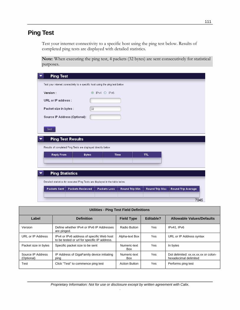
111
Proprietary Information: Not for use or disclosure except by written agreement with Calix. .
Ping Test Test your internet connectivity to a specific host using the ping test below. Results of completed ping tests are displayed with detailed statistics.
Note: When executing the ping test, 4 packets (32 bytes) are sent consecutively for statistical purposes.
Utilities - Ping Test Field Definitions
Label Definition Field Type Editable? Allowable Values/Defaults
Version Define whether IPv4 or IPv6 IP Addresses are pinged.
Radio Button Yes IPv4‡, IPv6
URL or IP Address IPv4 or IPv6 address of specific Web host to be tested or url for specific IP address.
Alpha-text Box Yes URL or IP Address syntax
Packet size in bytes Specific packet size to be sent Numeric-text Box
Yes In bytes
Source IP Address (Optional)
IP Address of GigaFamily device initiating ping
Numeric-text Box
Yes Dot delimited: xx.xx.xx.xx or colon-hexadecimal delimited
Test Click "Test" to commence ping test Action Button Yes Performs ping test

112
Proprietary Information: Not for use or disclosure except by written agreement with Calix. .
Ping Test Results
Reply From URL or IP address of host being tested Info Only No Recognizable URL or IP Address
Bytes Bytes received from the pinged host Info Only No Number of bytes
Time Time ping reply was received from host Info Only No Date and time
TTL Total router "hops" before packet times out.
Info Only No Numeric
Ping Statistics
Packets Sent Number of packets sent to the host Info Only No Total number of packets sent per ping request.
Packets Received Number of packets received back from the host
Info Only No Total number of packets received per ping request.
Packets Loss Number of test packets sent by the unit minus the number of packets received back by the unit
Info Only No Percentage of total packets versus packets lost.
Round Trip Min Minimum elapsed time for a ping-test packet to be sent by the GigaFamily device and received back from the host by the GigaFamily device
Info Only No Round trip minimum time in milli-seconds.
Round Trip Max Maximum elapsed time for a ping-test packet to be sent by the GigaFamily device and received back from the host by the unit
Info Only No Round trip maximum time in milli-seconds.
Round Trip Average Average amount of elapsed time for a ping-test packet to be sent by the GigaFamily device and received back from the host by the unit
Info Only No Average round trip time for all 4 packets sent.

113
Proprietary Information: Not for use or disclosure except by written agreement with Calix. .
Traceroute Traceroute is used to determine the route taken by packets across a network. Each test reports the round trip times for 3 ICMP packets. Each response shows the maximum number of hops displayed in the first column. The test repeats until the host is reached or the maximum hop count of 30 is reached. The times for each ICMP packet are displayed in the table. An asterisk (*) in a field means that no-response was received for the ICMP packet request.
Utilities - Traceroute Field Definitions
Label Definition Field Type Editable? Allowable Values/Defaults
Version Specify whether the traceroute command is applied to an IPv4 or IPv6 IP address.
Radio Button
Yes IPv4‡, IPv6
Enter a URL or IP Address
Enter the URL or IP address of the destination host
Alpha-text Box
Yes Recognizable URL or IP Address
Mode Select the Traceroute protocol Radio Button
Yes ICMP, UDP
Enable Reverse DNS
Enable or Disable reverse DNS execution. With reverse DNS enabled, an IP address search provides domain name registry and registry table information. You may be able to identify spammers or malicious attacks on your firewall by using reverse DNS lookup. Also useful in determining the ISP name for a particular IP address.
Radio Button
Yes Enable/Disable
Start Trace Initiate the traceroute request Action Button
Yes Initiate traceroute
Traceroute Results
Hops Maximum number of hops (up to 30) Info Only No Numeric up to 30
Time 1, 2, 3 Time of round trip for each ICMP packet from hop to hop
Info Only No Time value in milli-seconds
Host/IP Address Displays URL or IP address of traceroute host
Info only No Recognizable URL or IP Address

114
Proprietary Information: Not for use or disclosure except by written agreement with Calix. .
This site performs a reverse DNS lookup of an IP address by searching domain name registry and registrar tables. IP addresses are four numbers in the range of 0 to 255 separated by periods.
You may be able to identify the domain name of a spammer sending you spam email or the domain name of a computer trying to break into your firewall or someone trying to hack your system.
You may also be able to use this information to determine the name of the internet service provider assigned to a particular IP address.
System Log The system log provides an accounting of significant gateway device events.

115
Proprietary Information: Not for use or disclosure except by written agreement with Calix. .
Utilities - System Log Field Definitions
Label Definition Field Type Editable? Allowable Values/Defaults
Refresh Interval -Manual Refresh
Allows the System Log to be refreshed manually or automatically as well as setting the auto-refresh intervals
Radio Button with
Action Button
Yes See options directly below
Manual Refresh Allows for on-demand refresh of the System Log
"Manual Refresh"
button and a "Refresh" radio button for manual
refresh
Yes Manual Refresh ‡ Action Radio Button with Refresh Action Button
Auto Refresh Allows and schedules auto-refresh of the System Log
"Auto Refresh"
button along with a pull-down list of auto refresh
intervals
Yes Auto Refresh Radio Button with Refresh Action Button Auto refresh intervals list: Real time, 10, 20, 30 seconds, or 1 minute ‡ Manual "Refresh" Radio Button
Reboot Behavior Controls System Log reboot behavior for clearing or saving the System Log information
N/A N/A N/A
Clear on Reboot When chosen, clears the System Log on reboot
Clear on Reboot action button
Yes Clear on Reboot
Save on Reboot When chosen, saves the System Log on reboot
Save on Reboot action button
Yes Save on Reboot
Save Log Click button to save SystemLog to your PC Action Button
No Save Log action button
System Log Table Field Definitions
Date Date of significant event Info Only No Date format: mm/dd/yy
Time Time of significant RSG event Info Only No Time format: hh:mm:ss AM/PM
System System that experienced the event Info Only No System event Name
Action Device response to the event Info Only No System Response

116
Proprietary Information: Not for use or disclosure except by written agreement with Calix. .
Firewall Log The Firewall Log page provides a table of the most recently dropped packets by the firewall. The output includes information on:
Source MAC Address Destination MAC Address Source IP Address Destination IP Address Packet protocol Source Port Assignment Destination Port Assignment
Utilities - Firewall Log Field Definitions
Label Definition Field Type
Editable? Allowable Values/Defaults
Time Displays the date and time the log was captured
Display Only
No date format: mm/dd/yy time format: hh:mm:ss AM/PM
Details Displays MAC Address, IP Address, Packet Protocol, and Port Assignment information.
Display Only
No N/A
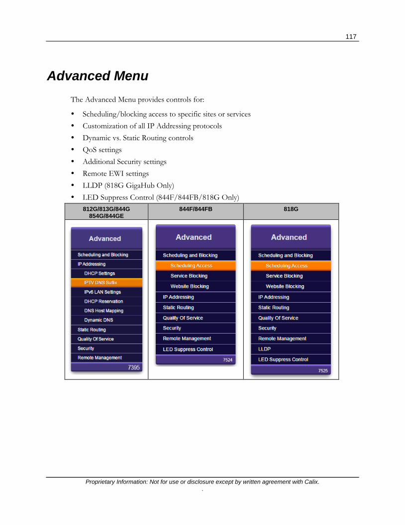
117
Proprietary Information: Not for use or disclosure except by written agreement with Calix. .
Advanced Menu The Advanced Menu provides controls for:
Scheduling/blocking access to specific sites or services Customization of all IP Addressing protocols Dynamic vs. Static Routing controls QoS settings Additional Security settings Remote EWI settings LLDP (818G GigaHub Only) LED Suppress Control (844F/844FB/818G Only)
812G/813G/844G 854G/844GE
844F/844FB 818G

118
Proprietary Information: Not for use or disclosure except by written agreement with Calix. .
Scheduling and Blocking Overview Scheduling and Blocking allows for the configuration of network access, service blocking, and website blocking.
Note: Features listed below can be customized under the Advanced > Scheduling and Blocking tab of the EWI.
Scheduling Access (on page 119) - Limits can be applied to LAN devices as to the time and day these devices can access the Internet. Configurable by device name or MAC address.
Service Blocking (on page 120) - Service blocking prevents specific devices from accessing internet applications. Blocking is accomplished by creating an association between a service and device name or IP address.
Website Blocking (on page 123) - Website blocking prevents specific internet sites from being accessible. Blocking is accomplished by associating a specific URL with a device name or IP address.

119
Proprietary Information: Not for use or disclosure except by written agreement with Calix. .
Scheduling Access
Access Scheduler sets Internet access rules for LAN devices. Scheduled devices are displayed in the Device Access List.
Advanced- Scheduling and Blocking - Scheduling Access Field Definitions
Label Definition Field Type Editable? Allowable Values/Defaults
Device If Device Radio Button is chosen, Drop-down List of device names is displayed
Radio Button and Drop-down
List
Yes Alphanumeric Names Default: Connected LAN devices
MAC Address If MAC Address is chosen, Alpha-text box is displayed
Radio Button and Alpha-text
Box
Yes Colon delimited (xx:xx:xx:xx:xx:xx)
Days of the week to allow Internet Access
Check days of week to allow LAN devices Internet access
Check Box Yes Selectable by day of week
Time of day ranges Set the hours of the day devices are allowed Internet access
Drop-down List
Yes Select pre-defined start and stop times for schedule range
Add Add the chosen device’s Internet access schedule
Action Button
Yes Click to apply and save changes
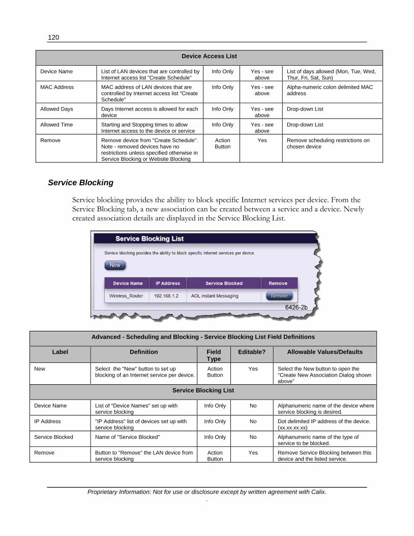
120
Proprietary Information: Not for use or disclosure except by written agreement with Calix. .
Device Access List
Device Name List of LAN devices that are controlled by Internet access list "Create Schedule"
Info Only Yes - see above
List of days allowed (Mon, Tue, Wed, Thur, Fri, Sat, Sun)
MAC Address MAC address of LAN devices that are controlled by Internet access list "Create Schedule"
Info Only Yes - see above
Alpha-numeric colon delimited MAC address
Allowed Days Days Internet access is allowed for each device
Info Only Yes - see above
Drop-down List
Allowed Time Starting and Stopping times to allow Internet access to the device or service
Info Only Yes - see above
Drop-down List
Remove Remove device from "Create Schedule". Note - removed devices have no restrictions unless specified otherwise in Service Blocking or Website Blocking
Action Button
Yes Remove scheduling restrictions on chosen device
Service Blocking
Service blocking provides the ability to block specific Internet services per device. From the Service Blocking tab, a new association can be created between a service and a device. Newly created association details are displayed in the Service Blocking List.
Advanced - Scheduling and Blocking - Service Blocking List Field Definitions
Label Definition Field Type
Editable? Allowable Values/Defaults
New Select the "New" button to set up blocking of an Internet service per device.
Action Button
Yes Select the New button to open the "Create New Association Dialog shown above"
Service Blocking List
Device Name List of "Device Names" set up with service blocking
Info Only No Alphanumeric name of the device where service blocking is desired.
IP Address "IP Address" list of devices set up with service blocking
Info Only No Dot delimited IP address of the device. (xx.xx.xx.xx)
Service Blocked Name of "Service Blocked" Info Only No Alphanumeric name of the type of service to be blocked.
Remove Button to "Remove" the LAN device from service blocking
Action Button
Yes Remove Service Blocking between this device and the listed service.

121
Proprietary Information: Not for use or disclosure except by written agreement with Calix. .
By clicking the New action button on the Service Blocking List screen, an association can be created between a specific service and a specific device.
Advanced - Scheduling and Blocking - Create New Association
Label Definition Field Type Editable? Allowable Values/Defaults
Service A list of service rules previously configured for service blocking
Drop-down List
Yes - see below Previously configured service blocking rules appear in this drop-down list.
View Button to "View" an info only chart listing: "Service Rule", "Protocol" type, "Port Start", "Port End", and "Port Map" for the chosen "Service" pull down menu
Action Button Yes View only
New Reveals the "Create New Service Rule" page used to create a new service to be added to the "Service" pull down list. "Create a New Service Rule" consists of "Name" field, "Protocol" pull down list, "Clear Fields" radio button, "Port Start" field, "Port End" field, "Port Map" field and "Apply" and "Cancel" radio buttons - See Create New Service Rule below
Action Button Yes See next section below.
Associate Service with Device
"Device" button used to associate selected name on pull down with the above listed "Service"
Action Button Yes Device button with alphanumeric list of devices - Device or IP Address
Associate Service with IP Address
"IP Address" button used to reveal a field for entering the IP Address of a device to be associated with the above listed "Service"
Action Button Yes Device button with alphanumeric list of devices - Device or IP Address
Apply/Cancel Button
"Apply" radio button applies and saves the "Create New Rule" settings into the Service Rule Chart and pull down "Services " list "Cancel" radio button cancels application of the service rule setting on the "Create New Service Rule" page and exits the page
Action Button Yes Apply and Save changes or Cancel

122
Proprietary Information: Not for use or disclosure except by written agreement with Calix. .
By clicking the New Service action button in the Create New Association screen, rules can be configured for specific services.
Advanced - Scheduling and Blocking - Create New Service Rule
Label Definition Field Type Editable? Allowable Values/Defaults
Name Name of the new service blocking rule to create
Drop-down List Yes Alpha-numeric name
Protocol Packet protocol to be used for the service rule
Drop-down List No TCP, UDP, or Both Default: TCP
Clear Fields Use the "Clear Fields" radio button to clear the "Name", "Port Start", "Port End" and "Port Map" fields in the "Create New Service Rule" section
Action Button Yes Clear fields radio button.
Port Start Starting TCP or UDP port number to that is affected by the blocking rule.
Alpha-numeric Text
Yes Port 1 through 65535
Port End Ending TCP or UDP port number to that is affected by the blocking rule.
Alpha-numeric Text
Yes Port 1 through 65535
Port Map Indicates the range of port numbers allowable.
Alpha-numeric Text
Yes Port 1 through 65535
Apply/Cancel Apply and Save or Cancel the changes to the service rule
Action Button Yes Apply or Cancel radio button

123
Proprietary Information: Not for use or disclosure except by written agreement with Calix. .
Website Blocking
Website blocking provides the ability to block specific websites per device or IP address.
Advanced - Scheduling and Blocking - New Website Blocking Field Definitions
Label Definition Field Type Editable? Allowable Values/Defaults
New Select the "New" button to set up blocking of a specific website per device or IP address
Action Button
Yes Create Blocking for a website.
List of Blocked Websites
Device Name Specific Device or List of all devices tagged for blocking
Info Only No Static Table Default: All Devices
IP Address Specific IP Address or all IP addresses associated with a particular device
Info Only No Static Table Default: Device Button Selected
Website Blocked Specific website to be blocked Info Only No URL of website to be blocked (dot delimited format)
Remove Button to Remove the network device from website blocking
Action Button
Yes Remove radio button

124
Proprietary Information: Not for use or disclosure except by written agreement with Calix. .
Choosing New from the screen above opens the "Create New Association" window where specific websites, devices, or IP addresses may be blocked.
Advanced - Scheduling and Blocking - Create New Association Field Definitions
Label Definition Field Type Editable? Allowable Values/Defaults
New Select the "New" button to set up blocking of a specific website per device or IP address
Action Button Yes Create Blocking for a website.
Create New Association
Website Address Input a website address that is to be blocked
Alpha-numeric Text
Yes Alpha-numeric text in URL format
Associate Website with Device
Choose a currently connected network device to block the URL input above
Radio Button with Drop-down
List
Yes Default: Device Button Selected Default: Drop-down List "All Devices"
Associate Website with IP Address
Choose a currently connected network device by inputting its IP address
Radio Button with Numeric
Text
Yes Dot-delimited IP address Default: Radio Button Not Selected Default: All IP addresses
Apply/Cancel Apply creates an association as provisioned above and saves the association. Cancel discards all changes
Action Button Yes Apply and Save changes.

125
Proprietary Information: Not for use or disclosure except by written agreement with Calix. .
IP Addressing Overview IP Addressing settings allow for the configuration of WAN, DHCP, and DNS settings across the network.
Note: Features listed below can be customized under the Advanced > IP Addressing tab of the EWI.
DHCP Settings (on page 126) - DHCP server configuration, IP addressing reservations, server lease times, as well as DNS server parameters are configured here.
IPV6 LAN Settings (on page 129) - Enable or Disable IPv6 addressing and define the appropriate parameters.
DHCP Reservation (on page 130) - DHCP reservations allow for the permanent allocation of a DHCP address to a client, even after a reboot.
DNS Host Mapping (on page 131) - DNS Host Mapping creates a static host name for a specific IP address at the router. Both WAN and LAN IP addresses can be mapped here.
Dynamic DNS (on page 132) - Dynamic DNS associates a WAN IP address with a specific host name and updates the DNS server when the WAN IP address changes.
Note: The Dynamic DNS service is hosted through www.dyndns.com (http://www.dyndns.com)

126
Proprietary Information: Not for use or disclosure except by written agreement with Calix. .
DHCP Settings
DHCP Settings define the LAN addressing parameters for your device to allocate IP addresses to LAN devices.

127
Proprietary Information: Not for use or disclosure except by written agreement with Calix. .
Advanced - IP Addressing - DHCP Settings Field Definitions
Label Definition Field Type
Editable? Allowable Values/Defaults
DHCP Host Name Defined host name for the DHCP service. Alpha text box
Yes Alpha-numeric string.
Domain Name Assigned Domain Name for the IP Address associated with this GigaFamily device
Alpha text box
Yes Alpha-numeric string.
DHCP server state Set the "Enabled" or "Disabled" state of the unit to allocate IP addresses to attached LAN devices
Radio Button
Yes Enable or Disable the DHCP Server
Device IP Address The IP Address of the device Numeric Yes Dot delimited, xx.xx.xx.xx
Beginning IP Address The first assignable IP address for LAN devices Numeric Yes Dot delimited, xx.xx.xx.xx
Ending IP Address The last assignable IP address for LAN devices Numeric Yes Dot delimited, xx.xx.xx.xx
Subnet Mask The assigned "Subnet Mask" is used to split and confine traffic to one network. A subnet mask keeps all local network traffic local and only routes Internet traffic to the Internet preserving network resources
Numeric Yes Dot delimited, xxx.xxx.xxx.xxx Default: 255.255.255.0
DHCP Server Lease Time
The length of time the DHCP server lease remains active without renewing
Alpha-numeric
Text
Yes Enter lease time in Days, Hours, and Minutes
DHCP Reservation Sticky: Once the router initially assigns a particular IP address to a client (laptop, tablet, smart phone, etc.) the client keeps that same address until the router is rebooted. Upon reboot, the router attempts to restore the existing DHCP address. This is the default behavior. In this mode, leases expire and are re-issued using the same IP address if possible. Permanent: Once the router assigns a particular address to a client, the client always gets that address until the router is rebooted. Upon reboot, a different address is assigned to the client however the previous lease/IP address are retained. Note: Usage of "permanent" may result in exhaustion of the IP address pool and should be used only in rare circumstances. Please contact your operator before using permanent. Note: Performing a factory reset restores the default behavior (Sticky).
Radio Button
Yes Sticky‡ or Permanent
Servers allocated with DHCP requests - DHCP DNS Type
If Default Servers are selected, assigned DNS server (192.168.1.1) is passed to LAN-side DHCP clients during Offer/ACK messaging . If Custom Servers is selected, the primary and secondary DNS servers provide the URL to IP translation for a specific site (the ISP assigns DNS server addresses). Note: This behavior is dependent on NAT settings as well. With NAT enabled, whether custom or default servers are chosen, the GigaCenter always acts as the DNS proxy agent to LAN side clients, behaving as the default server (192.168.1.1). If NAT is disabled, Custom server information from the ISPs DHCP offers will be sent (when this field is set to Custom Servers).
Radio Button
Yes Default Servers ‡ or Custom Servers Note: If you enable Dynamic Routing (RIP) without disabling NAT, an error message appears reminding you to disable NAT before proceeding.
Apply Apply and Save changes to DHCP settings Action Button
Yes Apply and save changes
This field defines the DNS-Server IP addresses that will be passed to LAN-side DHCP-clients in the Offer/Ack messages. - If "Default" is selected, the GigaFamily device local LAN host IP (192.168.1.1) will be sent.

128
Proprietary Information: Not for use or disclosure except by written agreement with Calix. .
IPTV DNS Suffix
IPTV DNS suffixes can be added to avoid having to implement a high number of static IP Hosts for IGMP enabled IPTV services. In this configuration, HSIA
Advanced - IP Addressing - IPTV DNS Suffix Field Definitions
Label Definition Field Type Editable? Allowable Values/Defaults
DNS URL name For adding new DNS URL's that include the IPTV DNS Suffix
Alpha text box Yes Dot-delimited, in the format <channel.iptv.website url>
Apply Adds the newly created DNS Suffix to the list (directly below)
Radio Button Yes Apply the DNS suffix
IPTV DNS Suffix List URL Displays the DNS Suffix created above Alpha text box No N/A
Remove Removes DNS Suffix entries from the list Radio Button Yes Remove

129
Proprietary Information: Not for use or disclosure except by written agreement with Calix. .
IPv6 LAN Settings
IPv6 LAN settings determine whether IPv6 addressing will be supported on this GigaFamily device and how it functions.
Advanced - IP Addressing - IPv6 LAN Settings
Label Definition Field Type Editable? Allowable Values/Defaults
Select LAN Select the LAN type. In this release, only Primary Bridge is available.
Drop-down List
Yes Primary Bridge
IPv6 Status Enable or Disable IPv6 address support Radio Button
Yes Enabled, Disabled
DHCPv6 Server Enable or Disable a DHCPv6 capable server. Enabled (Stateful) specifies a standard DHCPv6 server while Enable (Stateless) uses the Stateless Address Auto-Configuration (SLAAC) method to obtain IPv6 addresses.
Radio Button
Yes Enabled (Stateful), Enable (Stateless), Disabled
Name Server Mode Select whether the default Name Server mode is used (DNS servers used by the WAN) or a custom DNS server is available. For custom mode, you must enter a Primary and Secondary DNS server IP address.
Radio Button
Yes Default, custom

130
Proprietary Information: Not for use or disclosure except by written agreement with Calix. .
DHCP Reservations
DHCP reservation leases a permanent DHCP allocated address to a client and displays a list of these reservations.
Advanced - IP Addressing - DHCP Reservations Field Definitions
Label Definition Field Type Editable? Allowable Values/Defaults
Select Device type or manually enter a MAC address
Select the type of LAN device identifier, "Device" or a "MAC Address", to associate with an IP Address Choosing the "Device" button reveals a pull down list used to select the LAN device to be associated with an "IP Address" Choosing the "MAC Address" button reveals a field used to identify the LAN device to be associated with an "IP Address"
Radio Button
Yes Choose Device ‡ or MAC Address. If Device is chosen, select a device from the drop-down list. If MAC address is chosen, default is Null.
Select an IP address to associate with a MAC address
Select the "IP Address" from the pull down range of IP Addresses to be associated with the "Devices" and "MAC Addresses" connected to the unit
Drop-down List
Yes IP Addresses from the drop-down list. Range: 192.168.1.2 through 192.168.1.254 Default: 192.168.1.2
Apply "Apply" radio button applies and saves the "DHCP Reservation" settings
Action Button
Yes Applies and saves changes

131
Proprietary Information: Not for use or disclosure except by written agreement with Calix. .
DHCP Reservation List
Device Name Device Name selected from above Info Only No Alpha-numeric
MAC Address MAC Address input above Info Only No Numeric - MAC address format: xx:xx:xx:xx:xx:xx
IP Address IP Address selected from the drop-down list above
Info Only No Dot delimited IP Address xx.xx.xx.xx
Remove Remove the LAN device specified from the DHCP Reservation List
Action Button
Yes Remove the device
DNS Host Mapping
DNS host mapping creates a static host name for the specified IP address in the DSL router. WAN and LAN IP addresses are supported. A list of DNS Host mappings is also displayed.
Advanced - IP Addressing - DNS Host Mapping Field Definitions
Label Definition Field Type Editable?
Allowable Values/Defaults
DNS Host Name DNS Host Name to be associated with the DNS IP Address
Alpha-numeric Text Yes Alphanumeric Default: Null
DNS IP Address DNS IP Address to be associated with the above DNS Host Name
Alpha-numeric Text Yes Dot delimited IP Address (xx.xx.xx.xx) Default: Null
Apply "Apply" radio button applies and saves the "DNS Host Mapping List"
Action Button Yes Click to apply and save DNS Host Mapping
DNS Host Mapping List
IP Address IP Address for the WAN or LAN Static Host
Info Only No Dot delimited IP Address (xx.xx.xx.xx)
DNS Name DNS Name of the Static Host Info Only No Alpha-numeric text
Remove Click to remove the DNS Host IP Address from the Host Mapping table
Action Button Yes Click to remove mapping

132
Proprietary Information: Not for use or disclosure except by written agreement with Calix. .
Dynamic DNS
Dynamic DNS associates the WAN IP address of your router with a host name. Dynamic DNS automatically updates DNS servers upon WAN IP address change. Dynamic DNS (DDNS) is provided through www.dyndns.com.
Advanced - IP Addressing - Dynamic DNS Field Definitions
Label Definition Field Type Editable? Allowable Values/Defaults
Dynamic DNS state Select "Enabled" or "Disabled" Dynamic DNS state If DDNS is set to Disabled, the credential options are not displayed.
Radio Button Yes Enabled or Disabled ‡
Credentials for www.dyndns.com
Username Enter "Username" in field to access data base that associates WAN IP address of RSG with a host name
Alpha-numeric Text Yes AlphaNumeric Default: Null
Password Enter "Password" in field to access data base that associates WAN IP address of RSG with a host name
Alpha-numeric Text Yes AlphaNumeric Default: Null
Show Show the password Radio Button Yes If selected, actual password is displayed. If not checked, password is masked (all "bullets") Default: Values are masked
Dynamic DNS hostname
Enter the DNS host name. The dynamic DNS service will automatically update DNS servers with any WAN IP address change to the RSG
Alpha-numeric Text Yes AlphaNumeric Default: Null
Apply "Apply" radio button applies and saves the "Dynamic DNS host name"
Action Button Yes Apply and Save Dynamic DNS security information

133
Proprietary Information: Not for use or disclosure except by written agreement with Calix. .
Static Routing Adding routes manually to the routing table is considered static routing. If a change or a failure occurs between two statically defined nodes, traffic will not be rerouted and must wait for the failure to be resolved by the administrator. A list of assigned static routes is also provided.
Advanced - Routing - Static Routing Field Definitions
Label Definition Field Type Editable? Allowable Values/Defaults
Destination IP Manually add the IP address of a connected device to the gateway routing table
Numeric Yes Dot delimited xx.xx.xx.xx Default: 0.0.0.0
Subnet Mask Manually add the Subnet Mask of the connected device to the gateway routing table
Numeric Yes Dot delimited xx.xx.xx.xx Default: 255.0.0.0
Gateway IP Manually add the Gateway IP address to the gateway routing table
Numeric Yes Dot delimited xx.xx.xx.xx Default: 0.0.0.0
Apply "Apply" radio button applies and saves the "Static Routing" settings
Action Button
Yes Click to apply and save changes.
Static Routes
Destination IP IP address of connected device Info Only No Dot delimited xx.xx.xx.xx Default: 0.0.0.0
Subnet Mask Subnet Mask of connected device Info Only No Dot delimited xx.xx.xx.xx
Gateway IP Gateway IP address Info Only No Dot delimited xx.xx.xx.xx Default: 0.0.0.0
Edit (Remove) Remove selected static route from routing table
Action Button
No Click Remove to discard static route

134
Proprietary Information: Not for use or disclosure except by written agreement with Calix. .
Quality of Service Overview Quality of Service settings allow for the configuration of QoS prioritization rules across the network.
Note: Features listed below can be customized under the Advanced > Quality of Service tab of the EWI.
QoS (on page 134) - Quality of Service helps prioritize LAN to WAN packet movement in and out of a router. Options exist for classifying traffic type (video, voip, custom), traffic direction (upstream or down), and DSCP class. Can be applied to all traffic of a given type or only traffic from a given IPv4 or IPv6 address.
QoS (IPv4)
QoS prioritizes traffic types coming from the Upstream (LAN ports) or Downstream (WAN port) before standard data traffic. Traffic comes from or to specific applications or devices such as video players, game consoles, or voice adapters supporting Voice over IP (VoIP). By applying QoS to your network it can increase performance and prevent your network from becoming overloaded.

135
Proprietary Information: Not for use or disclosure except by written agreement with Calix. .
Advanced- Quality of Service - QoS Field Definitions
Label Definition Field Type Editable? Allowable Values/Defaults
QoS State Sets the "Enabled" or "Disabled" state for prioritizing the Quality of Service
Radio Button Yes "Enabled" ‡ or "Disabled"
New "New" radio button for creating a QoS rule
Radio Button Yes Create a new rule
Create New QoS Rule
QoS Type Select or create a QoS type from the pull down list: Video, VOIP, VOIP Signaling, Custom
Drop-down List Yes Choose Video, VOIP, VOIP Signaling, Custom‡ to create rule.
Rule Name (Custom only)
If QoS Type = Custom, then enter a name for the rule. Select or create a QoS type from the pull down list: Video, VOIP, VOIP Signaling, Custom
Alpha-numeric Text
Yes Alpha-numeric Text Default: Null
QoS Direction Choose whether QoS is enforced on the upstream or downstream traffic
Radio Button Yes Upstream ‡ or Downstream
DSCP Class (Custom only)
If QoS Type = Custom, Differentiated Services Code Point (DSCP) for coding QoS rule in IP packet to define "Class" of service
Drop-down List Yes Selectable options from pull down list of 7 classes of service as well as "Best Effort" ‡ and "Expedited Forwarding"
Queue Priority (Custom only)
Queue Priority of "Custom" QoS Type: High, Medium, Low, Best Effort
Drop-down List Yes Selectable options from pull down list of: High ‡, Medium, Low, Best Effort
IP Addresses (Custom only)
IP Addresses affected by the "QoS Rule": All or Defined
Radio Button Yes Choose either All IP Addresses ‡ or specific IP Addresses that need to abide by QoS Rules.
Source IP (Define Only)
Apply QoS rule to the source IP address Info only No N/A
IP Apply QoS rule to this source IP address Numeric Yes Dot delimited xx.xx.xx.xx
Network Mask Apply QoS rule to this source Netmask Numeric Yes Dot delimited xx.xx.xx.xx Default: 255.255.255.0
Port Range to Apply QoS rule to this source Port Range (2) Numeric Fields (to-from)
Yes Alphanumeric range, xxxx.... to xxx....
Destination IP Apply QoS rule to the destination IP Address
Info Only No N/A
IP Apply QoS rule to this destination IP Address
Numeric Yes Dot delimited xx.xx.xx.xx
Network Mask Apply QoS rule to this destination Netmask
Numeric Yes Dot delimited xx.xx.xx.xx Default: 255.255.255.0
Port Range to Apply QoS rule to this destination Port Range
(2) Numeric Fields (to-from)
Yes Alphanumeric range, xxx. . . to xxx. . . Default: Null
Apply "Apply" radio button applies and saves the "QoS Rule" settings
Radio Button Yes Click to apply and save changes
Cancel "Cancel" radio button cancels the "QoS Rule" settings
Radio Button Yes Click to cancel QoS Rule settings

136
Proprietary Information: Not for use or disclosure except by written agreement with Calix. .
New QoS Definitions List
Name Name of QoS rule Info Only "Edit" mode only
Info Only
Direction Data flow direction to which QoS rule is applied
Info Only "Edit" mode only
Info Only
DSCP Differentiated Services Code Point (DSCP) QoS class of service applied
Info Only "Edit" mode only
Info Only
Priority Priority of service applied Info Only "Edit" mode only
Info Only
Source Source of data to which QoS rule is applied
Info Only "Edit" mode only
Info Only
Destination Destination of data to which QoS rule is applied
Info Only "Edit" mode only
Info Only
Edit Edit this QoS rule Radio Button Yes Click Edit to change QoS Rule settings
Remove Remove this QoS rule Radio Button Yes Click Remove to discard this QoS Rule
Security Overview The Calix GigaFamily device incorporates various features that ensure overall network security.
Note: Features listed below can be customized under the Advanced > Security tab of the EWI.
Administrator Credentials (on page 137) - Administrator credentials prevent outsiders from accessing the gateway device's firmware settings.
Application Forwarding (on page 137) - The Application Forwarding feature allows a LAN device to receive incoming WAN traffic on a "per-application" basis. All traffic into the device associated with a given application is forwarded to the defined device. Associations are made between an application and a device name (or IP Address).
Port Forwarding (on page 141) - Similar to Application Forwarding, Port Forwarding allows a LAN device to received traffic on a port range basis. Traffic from a specific local port (or range of ports) and a specific remote port (or range) are specified.
Firewall (on page 138) - The Firewall blocks incoming IPv4 or IPv6 traffic based on the level of security desired. Pre-programmed services can be manipulated to allow or ban incoming or outgoing traffic based on the security level chosen.
DMZ Hosting (on page 146) - Digital Media Zone Hosting allows for the placement of any LAN device outside the firewall. Since this device, by definition, is now being hosted elsewhere, it can now be accessed using the WAN IP address (Connection Status page).
UPnP (on page 147) - UPnP (Universal Plug and Play) capable devices simplify the connection and implementation of devices into your network.

137
Proprietary Information: Not for use or disclosure except by written agreement with Calix. .
Administrator Credentials
Administrator credentials prevent outsiders from accessing the gateway device's firmware settings. After creating a username and password, you will need to enter them before you can access the gateway device's configuration settings.
Advanced- Security - Administrator Credentials Field Definitions
Label Definition Field Type Editable? Allowable Values/Defaults
Credentials Determines whether credentials are required to gain access to the gateway device's configuration settings
Radio Button Yes Required ‡ or Not Required Note: If Not Required is chosen, Login and Password fields are not displayed
Administrator - Login If credentials are required, the login name is entered here.
Alpha-numeric Text
Yes See the topic entitled Passwords for a list of allowable characters Default: admin
Administrator - Password
If credentials are required, the password is entered here.
Alpha-numeric Text
Yes See the topic entitled Passwords for a list of allowable characters. Default: See label shipped with GigaFamily device
Show When checkbox is checked, displays the un-masked password
Checkbox Yes When unchecked, the password is not displayed (masked with a string of bullets)
Apply Click to apply and save login and password
Action Button Yes Click to apply and save changes

138
Proprietary Information: Not for use or disclosure except by written agreement with Calix. .
Application Forwarding
Application Forwarding forwards the application's specified ports to the selected device or IP address. The subscriber can forward traffic from the WAN source to a local LAN device on a per-port basis.
Advanced- Security - Applications Forwarding List Field Definitions
Label Definition Field Type Editable? Allowable Values/Defaults
Create New Association - Application
Create a new association between an application’s specified port and a device or IP address. Applications are defined using the New Association radio button to the right.
Drop-down List
Yes Choose from a previously defined application from the drop-down list. If none exists, create one using the New radio button. To view previously created associations, click the View radio button. Default: Null
View This button allows the application rules for the selected application to be viewed
Radio Button Yes View Radio Button (see description above)
New This button allows a new application rule to be created
Radio Button Yes New Radio Button (see description above)
Application Forwarding List
Device Name Name of device to be associated with an application
Info Only No Listing device name
IP Address Name of IP address to be associated with an application
Info Only No IP Address of device to be forwarded
Application Forwarded Name of application being forwarded to device or IP address
Info Only No Application name being forwarded
Remove Eliminate the application forwarding association
Action Button Yes Click Remove to discard application forwarding rule

139
Proprietary Information: Not for use or disclosure except by written agreement with Calix. .
Upon clicking the New radio button described above, the Create New application Rule screen is displayed:
Advanced- Security - Create New Application Rule Field Definitions
Label Definition Field Type Editable? Allowable Values/Defaults
Name Assign a name to the new application rule
Alpha-numeric Text Yes Alpha-numeric text Default: Null
Protocol Protocol used for application forwarding Drop-down List Yes TCP ‡ , UDP, TCP/UDP
Clear Fields This button clears the fields to allow a new rule to be created
Radio Button Yes Clear all fields to allow entry of new rule
Port Start Enter the number of the application’s specified start port
Numeric Yes Numerals from 1 to 65535 Default: Null
Port End Enter the number of the application’s specified end port
Numeric Yes Numerals from 1 to 65535 Default: Null
Apply/Cancel "Apply" radio button applies and saves the "Create New Application Rule" settings or "Cancel" radio button cancels the "Create New Application Rule" settings
Action Button Yes Choose Apply to apply and save changes. Click Cancel to discard changes

140
Proprietary Information: Not for use or disclosure except by written agreement with Calix. .
Advanced - Security - Application Rule List (Create a new Association)
Protocol Protocol used for application forwarding Info Only No unless in edit mode
Info Only
Port Start The number of the application’s specified start port
Info Only No unless in edit mode
Info Only
Port End The number of the application’s specified end port
Info Only No unless in edit mode
Info Only
Edit Edit the application rule Radio Button Yes Click radio button to edit the rule
Remove Eliminate the application rule Radio Button Yes Click radio button to remove rule
Associate Application With
Associate an application with a device or IP address
Info Only N/A N/A
Device Select "Device" button to reveal a pull down list of defined devices for association with an application
"Device" button for selecting category and pull down list
for selecting device
Selectable button and selectable pull
down list
"Device" button and alphanumeric selectable pull down list Default: "Device" button Default: Wireless_Router
IP Address Select "IP Address" to reveal a field to enter an IP address for association with an application
"IP Address" button for selecting category and
numeric field for entering IP address
Selectable button and editable numeric field
"IP Address" button and a dot delimited numeric entry field Default: 0.0.0.0
Apply "Apply" radio button applies and saves the "Create New Association" settings
Radio Button Yes Apply and Save the Application Rule
Cancel "Cancel" radio button cancels the "Create New Association" settings
Radio Button Yes Cancel changes to the Application Rule
A Note about Application Forwarding
Effective with GigaFamily firmware release R11.1.90, support for the "Port Map" field on the Application Forwarding page of the GigaFamily Embedded Web Interface (EWI) has been discontinued. This affects all GigaFamily products that support Application Forwarding.

141
Proprietary Information: Not for use or disclosure except by written agreement with Calix. .
Change in Behavior In prior releases, a range of ports could be incorrectly mapped to a single port. For example, if the specified port to be mapped was port 7443 and a start and end range of 1000 to 1200 was defined, all communication directed to the external IP of the GigaFamily device with any port between 1000 and 1200 would be forwarded to port 7443 on the LAN device. This can create problems for certain applications that require a range of ports to be forwarded and as such, users are forced to create various rules depending on the requirements of each LAN device.
Starting in GigaFamily firmware release R11.1.90, the Port Map field has been removed from the Application Forwarding page in the EWI. As such, there now exists a one-to-one relationship among the ports forwarded to a LAN device. For example, if a start and end range of 2302 to 2400 is specified, the same range of ports is forwarded to the internal LAN device. In other words, the external port is the same port as the internal listening port. The intent is to create an easy to use method to provide connectivity to gaming/application servers such as Network Video Recorders (NVR) and the like.
Note: After the upgrade to R11.1.90 or above and if previously established application forwarding rules exist that include a port map rule, those rules will remain in place internal to each GigaFamily device however the EWI will no longer reflect the port map value since these fields have been removed.
When implementing this change in behavior, for anything more complex than basic application forwarding such as remapping an external port to an internal port, use the Port Forwarding option as found under Configuration > Security > Port Forwarding in Consumer Connect Plus or under Advanced > Security > Port Forwarding in the GigaFamily ONT EWI.
Port Forwarding
Port forwarding allows a remote device to connect to a local LAN device through a specific port or port range. Subscribers can forward traffic from the WAN source to a local LAN device based on a port or range of port addresses.

142
Proprietary Information: Not for use or disclosure except by written agreement with Calix. .
Note: Certain ports are reserved for system use and cannot be mapped individually. These ports include 8080, 30005, and 30006.
Advanced- Security - Port Forwarding Field Definitions
Label Definition Field Type
Editable?
Allowable Values/Defaults
New Create a new association between a remote device and a local LAN device through a specified port or port range
Radio Button
Yes Click to create a new port association
Port Forwarding Rules List
Local LAN Ports Number or range of numbers for the local LAN port
Info Only No N/A
Local LAN IP Address IP address of the local device Info Only No N/A
Protocol Protocol used to connect between local and remote devices
Info Only No N/A
Remote Ports Number or range of numbers for remote port
Info Only No N/A
Remote IP Address Remote IP address or all IP addresses associated with the remote port
Info only No N/A
Remove Remove the port forwarding association Radio Button
Yes Click Remove to discard the association

143
Proprietary Information: Not for use or disclosure except by written agreement with Calix. .
Advanced- Security - Create New Association Port Forwarding Field Definitions
Label Definition Field Type Editable? Allowable Values/Defaults
Local Port and IP
Clear Fields Clears the Local Port and IP fields to allow a new association to be created
Action Button Yes Click to clear previously entered data
Device Select the local LAN device to be connected to the remote device.
"Device" button with a drop-down
list of devices
Yes Radio button with drop-down list of currently connected local devices. Default: Device is selected but drop-down list is blank until devices are added.
IP Address Select "IP Address" to display a field to enter an IP address for association with the local device
Radio Button with numeric IP Address
field
Yes Click to enter IP Address (dot delimited xx.xx.xx.xx) Default: Not selected
Protocol Protocol used to connect between local and remote devices
Drop-down list
Yes TCP, UDP, TCP/UDP Default: TCP
Port Start Enter the number of the local port association’s specified start port
Numeric Yes 1-65535 Default: Null
Port End Enter the number of the local port association’s specified end port
Numeric Yes 1-65535 Default: Null

144
Proprietary Information: Not for use or disclosure except by written agreement with Calix. .
Remote Port and IP
Clear Fields Clears the Remote Port and IP fields to allow a new association to be created
Action Button Yes Click to clear previously entered data
All IP Addresses Select "All IP Addresses" to associate all remote IP addresses with a specified port or range of ports
Radio Button Yes Choose between associating all IP addresses or a specific IP address for creating a port forwarding rule (association) Default: Selected
IP Address Select "IP Address" to display a field to enter an IP address for association with the local device
Radio Button with numeric IP Address
field
Yes Click radio button to enter an IP address (dot delimited xx.xx.xx.xx) Default: Not Selected
Port Start Enter the number of the remote port association’s specified start port
Numeric Yes 1-65535 Default: Null
Port End Enter the number of the remote port association’s specified end port
Numeric Yes 1-65535 Default: Null
Apply/Cancel "Apply" radio button applies and saves the "Create New Association" settings or "Cancel" radio button cancels the "Create New Association" settings
Action Buttons
Yes Click Apply to apply and save changes. Click Cancel to remove port association.
Firewall
Activating the firewall is optional. When the firewall is activated, security is enhanced, but some network functionality will be lost.
Note: For additional information on system security settings, refer to the topic entitled System Security (on page 136) presented earlier in this guide.

145
Proprietary Information: Not for use or disclosure except by written agreement with Calix. .
Advanced- Security - Firewall Field Definitions
Label Definition Field Type Editable? Allowable Values/Defaults
Security Level
Security Off No filtering of incoming or outgoing traffic Radio Button Yes Turn security off Default: Selected (Security Off)
Low Security Block pre-defined traffic in per the "Blocked Services" settings. No blocking of outgoing traffic
Radio Button Yes Apply Low Security Settings Default: Not Selected
Medium Security Block pre-defined traffic in per the "Blocked Services" settings. No blocking of outgoing traffic
Radio Button Yes Apply Medium Security Settings Default: Not Selected
High Security Block pre-defined traffic in per the "Blocked Services" settings. Block pre-defined traffic out per the "Blocked Services" settings including DNS
Radio Button Yes Apply High Security Settings Default: Not Selected
Stealth Mode
Stealth Mode With "Stealth Mode" enabled, the device will not respond to all unsolicited WAN traffic including pings
Radio Button Yes Enable or Disable Stealth Mode Default: Disabled
Apply "Apply" radio button applies and saves the "Firewall" settings
Action Button Yes Click Apply to apply and save security settings.
If the security level above is set to Low, Medium, or High, the following table is displayed.
Note: Depending on the security level chosen, blocked services will change as it pertains to traffic in, traffic out, and ports affected.
Note: Blocked Services are disabled and are not displayed when the firewall security level is set to off.

146
Proprietary Information: Not for use or disclosure except by written agreement with Calix. .
Advanced- Security - Firewall Blocked Services Field Definitions
Label Definition Field Type Editable? Allowable Values/Defaults
Service Name of service that is set up for blocking
Info Only No N/A
Service Type Service Type Name that is set up for blocking
Info Only No N/A
Service Ports Defined service ports that are set up for blocking
Info Only No N/A
Traffic In Select whether you want downstream traffic to be blocked
Checkbox Yes Click the checkbox to enforce incoming traffic blocking Default: Not blocked
Traffic Out Select whether you want upstream traffic to be blocked
Checkbox Yes Click the checkbox to enforce outgoing traffic blocking Default: Not blocked
DMZ Hosting
DMZ hosting enables a LAN device to use the device WAN IP address as its own. DMZ places the LAN device outside the firewall.

147
Proprietary Information: Not for use or disclosure except by written agreement with Calix. .
Advanced- Security - DMZ Hosting Field Definitions
Label Definition Field Type Editable? Allowable Values/Defaults
DMZ State Enable or Disable DMZ hosting Radio Button Yes Select Enable or Disable Default: Disabled
Device (If DMZ = Enabled)
Select the LAN device to be hosted outside the firewall
Radio Button with Drop-down
list of Device names
Yes Device Default: Not Selected Drop-down list is alpha-numeric Default: Null field
IP Addressed (If DMZ = Enabled)
Select an IP address of a device to be hosted outside the firewall
Radio button with numeric field for IP address
Yes Default: IP Address radio button is selected IP address numeric field (dot delimited xx.xx.xx.xx) Default: Null field
Apply Apply button applies and saves the DMZ Host settings
Action Button Yes Apply to apply and save changes
DMZ Hosted Device Listing
Device Name Name of currently configured DMZ Hosted device
Info only No N/A
IP Address IP address of the device Info only No N/A
Remove Remove the associated device name and IP address from the DMZ Hosted list
Action Button Yes Removes the device from the DMZ list - the listed device will return to being hosted inside the DMZ.
UPnP
Universal Plug n Play is a network protocol whose general purpose is to enable zero-configuration, automatic discovery, and simple configuration of network services on a LAN. It was developed in 1998 by a consortium led by Microsoft. It allows devices to join a network, obtain an IP address, announce itself and its services, and learn about the presence and availability of other UPnP devices and services. UPnP devices are divided into 2 categories: Control Points (CP’s) and Controlled Devices (CD’s).

148
Proprietary Information: Not for use or disclosure except by written agreement with Calix. .
The most common use cases at present time are for printer discovery and installation, media server/player discovery and control, and Internet router control. UPnP can allow PC’s to discover and automatically identify and install drivers for network accessible printers. It allows network media players such as DLNA clients to automatically locate DLNA servers on the LAN. Internet routers can be discovered and various elements of control can be exerted upon them. Each of these functionalities is governed by a particular schema that fits within the UPnP protocol and those schemas are defined by individual UPnP Working Groups.
Advanced- Security - UPnP Field Definitions
Label Definition Field Type
Editable? Allowable Values/Defaults
UPnP state Universal Plug and Play (UPnP) can be enabled or disabled by selecting the appropriate buttons
Radio Button
Yes Enabled ‡ or Disabled
UPnP NAT-T state
When "Enabled" the UPnP Network Address Translator (NAT-T) masks the IP addresses of devices on the LAN behind the Home Gateway
Radio Button
Yes Enabled ‡ or Disabled
Apply Applies and saves the UPnP settings Action Button
Yes Apply and save changes

149
Proprietary Information: Not for use or disclosure except by written agreement with Calix. .
UPnP NAT-T List
IP Address The NAT assigned IP addresses of UPnP devices masked behind the Home Gateway
Info Only No N/A
ExPort Start Displays the starting port number for the external device that you want to allow access
Info Only No N/A
ExPort End Displays the ending port number for the external device that you want to allow access
Info Only No N/A
InPort Start Displays the starting port number for the internal device that you want to allow access
Info Only No N/A
InPort End Displays the ending port number for the internal device that you want to allow access
Info Only No N/A
Protocol Protocol being used to connect the external and internal devices via UPnP
Info Only No N/A
Edit Edit the UPnP NAT-T list Action Button
Yes Select the Edit Button
Remote Management Overview Remote Management settings allow for the configuration of a secure connection to the network from a remote location.
Note: Features listed below can be customized under the Advanced > Remote Management tab of the EWI.
Remote EWI (on page 149) - Provides added security when accessing the EWI from a remote location.
Remote EWI
Remote EWI enables access into the router from a WAN connection. To access your device remotely you will need to use http:// followed by the device IP address and the remote EWI port. For example: http://10.10.200.157:8080

150
Proprietary Information: Not for use or disclosure except by written agreement with Calix. .
Note: For deployments using the https:// protocol, the defined remote port number should be changed to 8443.
Advanced - Remote Management - Remote EWI Field Definitions
Label Definition Field Type Editable? Allowable Values/Defaults
Remote EWI state When "Enabled" the feature provides remote EWI access to the router from a WAN connection
Radio Button Yes Select Enable or Disable Default: Disabled
WAN IP Address The WAN IP Address that hosts the GigaCenter device.
Numeric Yes Dot delimited, x.x.x.x Default: 0.0.0.0
Remote EWI port Port on the Home Gateway for remote EWI access
Numeric Yes Numeric string Default: 8080
Apply Applies and saves the Remote EWI security settings
Action Button Yes Click to apply and save changes

151
Proprietary Information: Not for use or disclosure except by written agreement with Calix. .

152
Proprietary Information: Not for use or disclosure except by written agreement with Calix. .