call for proposals - unitn.itweb.unitn.it/files/download/17195/y-ct-201104_en.pdf · call for...
TRANSCRIPT

Clean Sky Joint Undertaking
Call SP1-JTI-CS-2011-02
- 1 -
European Commission Research Directorates
Call for Proposals:
CLEAN SKY RESEARCH and TECHNOLOGY DEVELOPMENT PROJECTS
(CS-RTD Projects):
Call Text
Call Identifier
SP1-JTI-CS-2011-02 Index Document track changes ............................................................................................................ 2 Specialised and technical assistance: ......................................................................................... 2 Introduction ................................................................................................................................ 3 Clean Sky – Eco Design............................................................................................................. 8 Clean Sky – Eco Design............................................................................................................. 9 Clean Sky – Green Regional Aircraft ...................................................................................... 24 Clean Sky – Green Rotorcraft .................................................................................................. 42 Clean Sky – Sustainable and Green Engines ........................................................................... 66 Clean Sky – Smart Fixed Wing Aircraft .................................................................................. 78 Clean Sky – Systems for Green Operations ............................................................................. 96 Clean Sky – Technology Evaluator........................................................................................ 103

Clean Sky Joint Undertaking
Call SP1-JTI-CS-2011-02
- 2 -
European Commission Research Directorates
Document track changes
Page/topic Original Correction or modification
Specialised and technical assistance: CORDIS help desk http://cordis.europa.eu/guidance/helpdesk/home_en.html
EPSS Help desk [email protected]
IPR help desk http://www.ipr-helpdesk.org

Clean Sky Joint Undertaking
Call SP1-JTI-CS-2011-02
- 3 -
European Commission Research Directorates
Introduction Via the Calls for Proposal, Clean Sky aims to incorporate Partners to address very specific tasks which fit into the overall technical Work Programme and time schedule. Due to the nature of these tasks, the Call is not set up using a set of themes, but it is conceived as a collection of very detailed Topics. The Call text therefore consists of a set of topic fiches, attached here. Each Topic fiche addresses the following points:
• Topic manager (not to be published) • Indicative start and Indicative End Dates of the activity • Description of the task • Indicative length of the proposal (where applicable) • Specific skills required from the applicant • Major deliverables and schedule • Maximum Topic Budget value • Remarks (where applicable)
The maximum allowed Topic budget relates to the total scope of work. A Maximum funding is also indicated. Depending on the nature of the participant, the funding will be between 50% and 75% of the Topic maximum budget indicated. It has to be noted that the Topic budget excludes VAT, as this is not eligible within the frame of Clean Sky. Recommendation to applicants:
nnnnnn yyyyyyyyyy
zzzzzzzzz
Make sure this total amount is below the value of the topic!! Better, keep at least 5% margin. Final amount is to be discussed in the negotiation.

Clean Sky Joint Undertaking
Call SP1-JTI-CS-2011-02
- 4 -
European Commission Research Directorates
Eligibility criteria All applicants are requested to verify their actual status of "affiliate" with respect to the members of the relevant ITD for whose topic(s) they wish to submit a proposal. Applicants who are affiliated to any leader or associate of an ITD will be declared not eligible for the topics of that ITD. Refer to art.12 of the Statute (Council Regulation (EC) No 71/2007 of 20 December 2007 setting up the Clean Sky Joint Undertaking) and to page 8 of the Guidelines. Number of Thresholds: As indicated in section 4.6 of the "Rules for Participation and Rules for Submission of Proposals and the related Evaluation, Selection and Award Procedures", each proposal will be evaluated on 6 criteria. For a Proposal to be considered for funding, it needs to pass the following thresholds:
• Minimum 3/5 score for each of the 6 criteria, AND
• Minimum 20/30 total score Only one Grant Agreement (GA) shall be awarded per Topic. Calendar of events: • Call Launch: 28 April 2011 • Call close: 28 July 2011, 17:00 • Evaluations (indicative): 19-23 September 2011 • Start of negotiations (indicative): 24 October 2011 • Final date for signature of GA by Partner: 30 November 2011 • Final date for signature of GA by Clean Sky JU: 16 December 2011 Recommendation The applicant is encouraged to apply for a PIC (Participant Identity Code) and to launch the process of validation as early as possible; this will speed up the process of negotiation in the event that your proposal is successful (see http://ec.europa.eu/research/participants/portal/appmanager/participants/portal)

Clean Sky Joint Undertaking
Call SP1-JTI-CS-2011-02
- 5 -
European Commission Research Directorates
Contacts: All questions regarding the topics published in this Call can be addressed to: [email protected] Questions received until 16 June 2011 will be analysed. Questions having a general value, either on procedural aspects or specific technical clarifications concerning the call topics, when judged worth being disseminated, will be published in a specific section of the web site (www.cleansky.eu), together with the answers provided by the topic managers. All interested applicants are suggested to consult periodically this section, to be updated on explanations being provided on the call content. Reference to TRL: When applicable or quoted in the text of topics, the applicants should be aware of the definition of Technology Readiness Levels, as per following chart, being TRL 6 the target for Clean Sky for all applicable technologies:

Clean Sky Joint Undertaking
Call SP1-JTI-CS-2011-02
- 6 -
European Commission Research Directorates
Looking for partners? The following link has been created on Clean Sky website. It points already to the websites of Austria, Czech Republic, France, and some more to be added, providing links to companies whose competences and capabilities can be of interest for the potential applicant seeking partners for their proposal: http://www.cleansky.eu/content/page/looking-partners
Clean Sky Joint Undertaking
Call SP1-JTI-CS-2011-02
- 7 -
European Commission Research Directorates
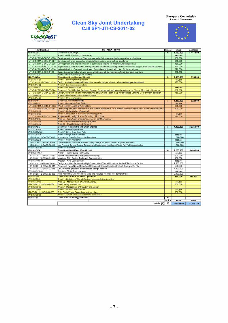
Identification topics VALUE MAX FUNDJTI-CS-ECO 6 1.530.000 1.147.500JTI-CS-ECO-01 1.530.000
JTI-CS-2011-2-ECO-01-026 Development of a bamboo fiber process suitable for aeronautical composites applications 150.000JTI-CS-2011-2-ECO-01-027 Development of an innovative bio resin for structural aeronautical structures 350.000JTI-CS-2011-2-ECO-01-028 Development and implementation of conductive coating for Magnesium sheets in a/c 160.000JTI-CS-2011-2-ECO-01-029 Application of selective laser melting and electron beam melting for direct manufacturing of titanium stator vanes 150.000JTI-CS-2011-2-ECO-01-030 Industrialisation of an ecolonomic out of autoclave polymerization for LRI demonstrator 520.000JTI-CS-2011-2-ECO-01-031 Green integrated polyurethane foams with improved fire resistance for airliner seat cushions 200.000
JTI-CS-ECO-02JTI-CS-GRA 3 1.835.000 1.376.250JTI-CS-GRA-01 185.000
JTI-CS-2011-2-GRA-01-038 185.000JTI-CS-GRA-02JTI-CS-GRA-03 1.650.000
JTI-CS-2011-2-GRA-03-004 900.000JTI-CS-2011-2-GRA-03-005 750.000
JTI-CS-GRA-04JTI-CS-GRA-05JTI-CS-GRC 3 1.230.000 922.500JTI-CS-GRC-01 800.000
JTI-CS-2011-2-GRC-01-006 500.000JTI-CS-2011-2-GRC-01-007 300.000
JTI-CS-GRC-02 JTI-CS-GRC-03 430.000
JTI-CS-2011-2-GRC-03-009 430.000JTI-CS-GRC-04JTI-CS-GRC-05 JTI-CS-GRC-06 JTI-CS-SAGE 3 4.300.000 3.225.000JTI-CS-SAGE-01 JTI-CS-SAGE-02 JTI-CS-SAGE-03 1.800.000
JTI-CS-2011-2-SAGE-03-012 1.800.000JTI-CS-SAGE-04 2.500.000
JTI-CS-2011-2-SAGE-04-015 1.500.000JTI-CS-2011-2-SAGE-04-016 1.000.000
JTI-CS-SAGE-05JTI-CS-SFWA 6 7.200.000 5.400.000JTI-CS-SFWA-01 600.000
JTI-CS-2011-2-SFWA-01-039 200.000JTI-CS-2011-2-SFWA-01-040 400.000
JTI-CS-SFWA-02 4.600.000JTI-CS-2011-2-SFWA-02-016 2.500.000JTI-CS-2011-2-SFWA-02-017 600.000JTI-CS-2011-2-SFWA-02-018 1.500.000
JTI-CS-SFWA-03 2.000.000JTI-CS-2011-2-SFWA-03-009 2.000.000
JTI-CS-SGO 2 850.000 637.500JTI-CS-SGO-01JTI-CS-SGO-02 600.000JTI-CS-2011-2-SGO-02-034 600.000JTI-CS-SGO-03 JTI-CS-SGO-04 250.000JTI-CS-2011-2-SGO-04-003 250.000JTI-CS-SGO-05JTI-CS-TEV 0
topics VALUE FUND
23 16.945.000 12.708.750
Area-03 - Large 3-shaft turbofan
Development of Innovative SLM-Machinery for High Temperature Aero Engine Applications
Design and Manufacture of a High Speed Wind Tunnel Model for the ONERA S1MA Facility
Morphing Skin Design Tools and DemonstrationArea02 – New Configuration
Clean Sky - Smart Fixed Wing Aircraft
Low Pressure Turbine Surface Temperature Measurement for Geared Turbo Fan Turbine Application
Non-metallic Pipes for Aeroengine Dressings
Area01 – Smart Wing Technology
totals (€)
Clean Sky - Systems for Green OperationsArea-01 - Definition of Aircraft Solutions and explotation strategies
Area03 – Flight Demonstrators
Area-02 - Management of Aircraft Energy
Area-05 - Aircraft-level assessment and exploitationClean Sky - Technology Evaluator
Solid State Power Controllers test benches
Final Assembly Line Assembly Jigs and Fixtures for flight test demonstrator
Area-03 - Management of Trajectory and MissionArea-04 - Aircraft Demonstrators
Area-04 - Geared Turbofan
EWIS safety analysis tool
Area-05 - Turboshaft
Advanced Pylon Noise Reduction Design and Characterisation through flight worthy PIV
Pattern measurements using laser scattering
CROR Partial propeller blade release design solution
Clean Sky - Sustainable and Green Engines
Area-05 - Environmentally friendly flight paths
Area-03 - Integration of innovative electrical systems
Area-03 - All electric aircraft
Area-04 - Mission and trajectory ManagementDesign, development and manufacturing of EMA and Test Set-up for advanced Landing Gear System actuation
Area-02 - Reduced Drag of rotorcraft
Adaptation kit design & manufacturing : APU drive
ITD - AREA - TOPICClean Sky - EcoDesignArea-01 - EDA (Eco-Design for Airframe)
Area-02 - EDS (Eco-Design for Systems)Clean Sky - Green Regional Aircraft
Design, manufacturing and impact test on selected panels with advanced composite materialArea-01 - Low weight configurations
Area-02 - Low noise configurations
Advanced Flight Control System – Design, Development and Manufacturing of an Electro Mechanical Actuator
Area-02 - Direct Drive Open RotorArea-01 - Geared Open Rotor
Area-04 - Installation of diesel engines on light helicopters
Clean Sky - Green RotorcraftArea-05 - New configurations
Area-06 - Eco Design for Rotorcraft
Wind Tunnel Testing of Active RotorGurney flap actuator, mechanism and control electronics for a Model scale helicopter rotor blade (Develop and su
Area-01 - Innovative Rotor Blades

Clean Sky Joint Undertaking
Call SP1-JTI-CS-2011-02 Eco Design
- 8 -
European Commission Research Directorates
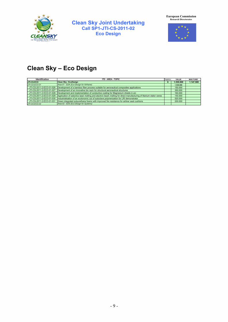
Clean Sky – Eco Design
Identification topics VALUE MAX FUNDJTI-CS-ECO 6 1.530.000 1.147.500JTI-CS-ECO-01 1.530.000
JTI-CS-2011-2-ECO-01-026 Development of a bamboo fiber process suitable for aeronautical composites applications 150.000JTI-CS-2011-2-ECO-01-027 Development of an innovative bio resin for structural aeronautical structures 350.000JTI-CS-2011-2-ECO-01-028 Development and implementation of conductive coating for Magnesium sheets in a/c 160.000JTI-CS-2011-2-ECO-01-029 Application of selective laser melting and electron beam melting for direct manufacturing of titanium stator vanes 150.000JTI-CS-2011-2-ECO-01-030 Industrialisation of an ecolonomic out of autoclave polymerization for LRI demonstrator 520.000JTI-CS-2011-2-ECO-01-031 Green integrated polyurethane foams with improved fire resistance for airliner seat cushions 200.000
JTI-CS-ECO-02
ITD - AREA - TOPICClean Sky - EcoDesignArea-01 - EDA (Eco-Design for Airframe)
Area-02 - EDS (Eco-Design for Systems)
Clean Sky Joint Undertaking
Call SP1-JTI-CS-2011-02 Eco Design
- 9 -
European Commission Research Directorates
Clean Sky – Eco Design
Identification topics VALUE MAX FUNDJTI-CS-ECO 6 1.530.000 1.147.500JTI-CS-ECO-01 1.530.000
JTI-CS-2011-2-ECO-01-026 Development of a bamboo fiber process suitable for aeronautical composites applications 150.000JTI-CS-2011-2-ECO-01-027 Development of an innovative bio resin for structural aeronautical structures 350.000JTI-CS-2011-2-ECO-01-028 Development and implementation of conductive coating for Magnesium sheets in a/c 160.000JTI-CS-2011-2-ECO-01-029 Application of selective laser melting and electron beam melting for direct manufacturing of titanium stator vanes 150.000JTI-CS-2011-2-ECO-01-030 Industrialisation of an ecolonomic out of autoclave polymerization for LRI demonstrator 520.000JTI-CS-2011-2-ECO-01-031 Green integrated polyurethane foams with improved fire resistance for airliner seat cushions 200.000
JTI-CS-ECO-02
ITD - AREA - TOPICClean Sky - EcoDesignArea-01 - EDA (Eco-Design for Airframe)
Area-02 - EDS (Eco-Design for Systems)

Clean Sky Joint Undertaking
JTI-CS-2011-2-ECO-01-026
- 10 -
Topic Description
CfP topic number Title
End date To + 24 JTI-CS-2011-2-ECO-01-026 Development of a bamboo fibres process suitable for aeronautical composites applications
Start date To
1. Topic Description
Bamboo is known to be a durable and efficient material that has been used for centuries in the building industry. The mechanical performance of the tree, and its capability to environmental resistance, suggest good fiber mechanical properties. Moreover, its production is easy, and many species have already been selected for their growing speed and their mechanical performances. However; there is yet no existing « infinite wire » weaved from the bamboo fibers which can be extracted from the plant. Therefore, the following tasks need to be realised in order to develop and characterize a bamboo-based bio-composite : - Determine the correct species that can be suitable for composite application, with respect to the bio-composite requirements (mechanical, growing time, existing fields, repeatability of the harvest, …) - Develop a low energy consumption process in order to weave a bamboo wire, and then braid a fabric, which will be further use for composite manufacturing. - Characterize the mechanical properties of the thread and the fabrics and improve the products. - Realize composite samples for mechanical and environmental evaluation, and compare them with state of the art technology (glass fiber composite) and other bio-fibers (comparison is based on bibliographic studies and material data from CS consortium companies). Impregnation will be realized with state of the art epoxy resins and commercially available bio-resins. Sample manufacturing will include sandwich parts (aluminium or nomex core) Tests to be performed are define below : - Physico-chemical evaluation : density, porosity detection, fibers degradation with temperature/ageing, etc, glass transition, interlaminar shear strength, … - Mechanical : Tension, compression, flexion, peeling, etc. - Environmental : Wet ageing, Fire resistance, acoustical characterization, etc. - Manufacture a demonstrator (for ex: part of a Falcon furniture) using the bamboo fabric. This part would be composed of 5 to 7 sandwich panels of approximately 0.5 m2, assembled by inserts and pins bonding (state of the art technologies).
2. Special skills, certification or equipment expected from the applicant The following skills and equipments are required: - Knowledge of the different bamboo species growing around the world, in order to be able to select the appropiate plant for aeronautic applications (and in respect with existing fields, food plantations, etc.) - Knowledge of possible processes leading to bamboo fibers extraction from the bamboo plant, with low energy consumption and low chemical products use (especially solvents) - Capability of weaving an infinite bamboo thread from smaller bamboo fibers - Capability of weaving a fabric from the bamboo thread - Capability of impregnating the fabric with epoxy resin - Capability of mechanical testing
Clean Sky Joint Undertaking
JTI-CS-2011-2-ECO-01-026
- 11 -
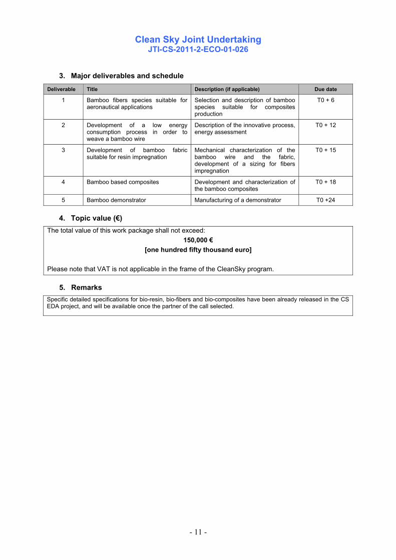
3. Major deliverables and schedule
Deliverable Title Description (if applicable) Due date
1 Bamboo fibers species suitable for aeronautical applications
Selection and description of bamboo species suitable for composites production
T0 + 6
2 Development of a low energy consumption process in order to weave a bamboo wire
Description of the innovative process, energy assessment
T0 + 12
3 Development of bamboo fabric suitable for resin impregnation
Mechanical characterization of the bamboo wire and the fabric, development of a sizing for fibers impregnation
T0 + 15
4 Bamboo based composites Development and characterization of the bamboo composites
T0 + 18
5 Bamboo demonstrator Manufacturing of a demonstrator T0 +24
4. Topic value (€) The total value of this work package shall not exceed:
150,000 € [one hundred fifty thousand euro]
Please note that VAT is not applicable in the frame of the CleanSky program.
5. Remarks Specific detailed specifications for bio-resin, bio-fibers and bio-composites have been already released in the CS EDA project, and will be available once the partner of the call selected.

Clean Sky Joint Undertaking
JTI-CS-2011-2-ECO-01-027
- 12 -
Topic Description
CfP topic number Title
End date To + 24 JTI-CS-2011-2-ECO-01-027 Development of an innovative bio-based resin for aeronautical applications
Start date To
1. Topic Description
The aim of this call is to develop an innovative bio-based resin system suitable for aeronautical applications (interiors and/or structures). The main innovation of this resin system must be linked to the use of innovative chemistry, based on non fossil based raw materials, and would allow a certain amount of recyclability of the matrix at the end of its life cycle. The green requirements for biopolymers are described below: • Biopolymers shall be produced from natural and renewable resources. • The production and cure cycle of biopolymers shall be energy extensive and result in lower CO2 emissions than those of comparable epoxy resins. • The production of composites with natural fibres and/or biopolymers shall be energy extensive. The total amount of CO2 emission per kg composite material shall be lower than the emission for state-of-the-art composites consisting of epoxy reinforced with organic or mineral fibres like carbon or glass • The quantity of bio-composite material required to replace state-of-the-art composites may be larger but: o The total mass of the structure may not increase o The scrap rate may not increase o The green requirements mentioned above must remain valid The main requirements of the matrix are listed below : - Non petrol, or fossil–based chemistry (if needed, land use should not interfere and compete with food production) - Tg wet > 120°C ; G1c > 300 J/m2 (TBC); E > 3 GPa; Water uptake: < 2.5 % - Potential to be adapted to the aircraft interiors FST (Fire, Smoke and Toxicity) and Heat Release requirements (rem : use of environmental critical flame retardants is prohibited) - Resistance to hydrolysis, chemicals - Easy processability (multi processes, large T,t process window) - Long pot-life - Low emission of Volatil Organic Substances (VOC) during in-service life - Clean manufacturing process from raw materials to final product (REACh compliant, low life cycle impact) The innovative matrix development can be linked to the use/development of bio-fibres that would be specifically adapted to this matrix. The development of this resin will be correlated to the following tasks : - Bibliographical study - Theoretical study of the innovative chemistry - Several resin formulations and associated characterization tests (Lap shear, open time, peel, G1C, Tg, rheological behaviour) in order to reach the requirements - Once the final formulation is set, production of small resin batches for industrial evaluation, completed with extensive testing of the resin - Impregnation of reinforcing fabrics with the resin, in order to manufacture mechanical samples for evaluation (tension, compression, impact, ageing, FST testing, peeling …)

Clean Sky Joint Undertaking
JTI-CS-2011-2-ECO-01-027
- 13 -
2. Special skills, certification or equipment expected from the applicant The following skills and equipments are required: - Knowledge and possibly preliminary work on innovative resin chemistry realised with bio-based raw materials. - Capability of resin formulation from laboratory experiments to small scale industrial batch production (minimum 2 L resin batch) - Capability of impregnating the resin with different type of fibres - Capability of producting and testing composite samples (physico-chemistry, mechanics, …)
3. Major deliverables and schedule
Deliverable Title Description (if applicable) Due date
N°1 Synthesis of bio-based resins for aeronautical applications
Theoretical and experimental work on innovative resin formulation.
T0 + 6
N°2 Bio-based resins test screening
Characterization of resins : Lap shear, open time, peel, G1C, Tg, rheological behaviour, etc.
T0 + 12
N°3 Process development and evaluation
Production of small resin batch, assessment for an industrial production
T0 + 18
N°4 Selection and maturation of the innovative system
Impregnation of reinforcing fibers with the innovative resin. Manufacturing and mechanical evaluation of the composite.
T0 + 24
4. Topic value (€) The total value of this work package shall not exceed:
350,000 € [three hundred fifty thousand euro]
Please note that VAT is not applicable in the frame of the CleanSky program.
5. Remarks Specific detailed specifications for bio-resin, bio-fibers and bio-composites have been already released in the CS EDA project, and will be available once the partner of the call selected.

Clean Sky Joint Undertaking
JTI-CS-2011-2-ECO-01-028
- 14 -
Topic Description
CfP topic number Title
End date To+24 JTI-CS-2011-2-ECO-01-028
Development and implementation of conductive coating for Magnesium sheets in a/c Start date To
1. Topic Description Introduction The development of conductive coating on Magnesium sheets will enable the use of Mg parts that will comply to the requirement of electrical bonding throughout the A/C. The requirement is safety driven and is an JAA, FAA requirement to prevent lightening or static electricity damage to the A/C The objective of this call is to develop a conductive coating for Magnesium to use on aircrafts parts, complying with standard aviation criteria: corrosion resistance and electrical resistivity requirements (5000µOhm/inch2) and all REACH regulations. Selected demonstrators must be tested to enable installation of Magnesium parts in aircrafts. The coating will be tested for corrosion resistance according to accepted aviation methods. Mechanical tests shall be carried out to ensure the process does not have any deleterious effects on the Magnesium properties. Work to be performed by the partners The quantitative requirement is mentioned in the description of the deliverable. - Develop an environmentally friendly conductive coating for Magnesium under REACH regulations that can be applied in a serial production line. - Perform conductivity tests. - Perform Salt Spray Tests (SST) according to ASTM B-117 - Coating shall be compatible with aviation paint systems. - Perform paint adhesive tests. - Perform an environment analysis of the coating production, including: materials to be used, energy used for the process, list of chemicals used in the process and the effect of the price of the coating - Perform mechanical tests on raw material samples, on coated material samples, on coated material with paint. Fatigue and static properties should be assessed. Base material to be used shall be Magnesium with specific mechanical properties similar or better than Al 6061, e.g. WE43.
2. Special skills, certification or equipment expected from the applicant - Rich experience in development of a wide range of coatings - Equipment to develop the conductive coating - Familiarity with Magnesium’s chemical and mechanical properties - Ability to perform salt spray tests according to ASTM’s requirements - Ability to perform mechanical test as requested and according to ASTM's requirements - Familiarity with aviation regulations and requirements - Ability to work under all REACh regulations - Equipment to perform the coating at pilot level to represent a serial production line

Clean Sky Joint Undertaking
JTI-CS-2011-2-ECO-01-028
- 15 -
3. Major deliverables and schedule
Deliverable Title Description (if applicable) Due date
D1 Methodological presentation and test plan - Document
1. Description of the preliminary solution 2. Description of the tests to be performed, expected results and major milestones
To+3
D2 First results - Technical results
1. Initial properties (mechanical and chemical) Mechanical on raw material: - 6 static samples (3 each direction L and T) - 2 Whölers curves (1 each direction L and T) (7 loads, 1 sample each load). Perform SST according to ASTM B-117 on 4 sample of raw material. Report will include surface properties with pictures, metallographic examinations and any if anomalies result from the SST. 2. Rough of Magnitude as environmental aspects
To+6
D3 Tests: 1. Resistivity 2. Paint adhesive – Technical report before SST
Tests specimens for resistivity measurement and paint adhesive tests on coated and coated and painted material. (3 samples per batch, 6 samples in total)
1. Perform resistivity tests and apply to a maximum of 5,000 µohm/inch2 before and 10,000 µohm/inch2 after the Salt spray test. 2. Perform paint adhesive tests according to specific request (Q+S)
To+12
D4.1 Corrosion testing – Technical report
Tests specimens for comparative SST evaluation and perform corrosion test according to ASTM B-117 report that will include surface properties with pictures, metallographic examination and any if anomalies result from the SST. (4 samples per lot, 12 samples in total)
1. After the implementation of the conductive coating.
2. After the implementation of the conductive coating and painted.
Perform a comparison table between the three lots (Use output of D2) and the results from the SST.
To+18
D4.2 Mechanical testing – Technical report
Perform static, dynamic and microscopic examination.
S-N curves and three static tests will be provided for each coated lot (coated and coated +paint) and for each direction (longitudinal and transverse). It means 4 S-N curves and 12 static test results. 12 samples for the static test 28 samples per the dynamic test (1 sample per load, 7 loads minimum required)
3 samples from the static test and 1 sample from each load of the dynamic test shall be examined under microscope
To+18
D5 Environment analysis – Technical report
Estimate the influence of the conductive coating process from all environment aspects including: energy consumption, pollution of gases, process waste, and cost analysis.
To+18
To+12
To+18

Clean Sky Joint Undertaking
JTI-CS-2011-2-ECO-01-028
- 16 -
D6 Demonstrator - Final technical report - Reference part
Adopt the conductive coating on a reference part and gather all data to a technical report (mechanical properties, chemical properties, environmental aspects and economic analysis for the process)
To+24
4. Topic value (€) The total value of this work package shall not exceed:
160,000 € [one hundred sixty thousand euro]
Please note that VAT is not applicable in the frame of the CleanSky program.
5. Remarks The aim is to bring the process to a TRL 6 stage. IPR shall be dealt with applicable documents to partners under FP7 as per Grant Agreement for Partners and Implementation Agreement (ftp://ftp.cordis.europa.eu/).
Clean Sky Joint Undertaking
JTI-CS-2011-2-ECO-01-029
- 17 -
Topic Description
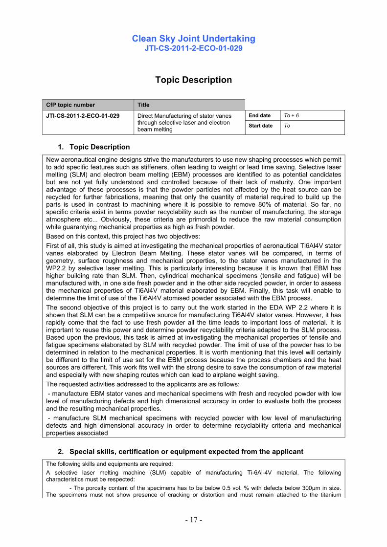
CfP topic number Title
End date To + 6 JTI-CS-2011-2-ECO-01-029 Direct Manufacturing of stator vanes through selective laser and electron beam melting Start date To
1. Topic Description
New aeronautical engine designs strive the manufacturers to use new shaping processes which permit to add specific features such as stiffeners, often leading to weight or lead time saving. Selective laser melting (SLM) and electron beam melting (EBM) processes are identified to as potential candidates but are not yet fully understood and controlled because of their lack of maturity. One important advantage of these processes is that the powder particles not affected by the heat source can be recycled for further fabrications, meaning that only the quantity of material required to build up the parts is used in contrast to machining where it is possible to remove 80% of material. So far, no specific criteria exist in terms powder recyclability such as the number of manufacturing, the storage atmosphere etc... Obviously, these criteria are primordial to reduce the raw material consumption while guarantying mechanical properties as high as fresh powder. Based on this context, this project has two objectives: First of all, this study is aimed at investigating the mechanical properties of aeronautical Ti6Al4V stator vanes elaborated by Electron Beam Melting. These stator vanes will be compared, in terms of geometry, surface roughness and mechanical properties, to the stator vanes manufactured in the WP2.2 by selective laser melting. This is particularly interesting because it is known that EBM has higher building rate than SLM. Then, cylindrical mechanical specimens (tensile and fatigue) will be manufactured with, in one side fresh powder and in the other side recycled powder, in order to assess the mechanical properties of Ti6Al4V material elaborated by EBM. Finally, this task will enable to determine the limit of use of the Ti6Al4V atomised powder associated with the EBM process. The second objective of this project is to carry out the work started in the EDA WP 2.2 where it is shown that SLM can be a competitive source for manufacturing Ti6Al4V stator vanes. However, it has rapidly come that the fact to use fresh powder all the time leads to important loss of material. It is important to reuse this power and determine powder recyclability criteria adapted to the SLM process. Based upon the previous, this task is aimed at investigating the mechanical properties of tensile and fatigue specimens elaborated by SLM with recycled powder. The limit of use of the powder has to be determined in relation to the mechanical properties. It is worth mentioning that this level will certainly be different to the limit of use set for the EBM process because the process chambers and the heat sources are different. This work fits well with the strong desire to save the consumption of raw material and especially with new shaping routes which can lead to airplane weight saving. The requested activities addressed to the applicants are as follows: - manufacture EBM stator vanes and mechanical specimens with fresh and recycled powder with low level of manufacturing defects and high dimensional accuracy in order to evaluate both the process and the resulting mechanical properties. - manufacture SLM mechanical specimens with recycled powder with low level of manufacturing defects and high dimensional accuracy in order to determine recyclability criteria and mechanical properties associated
2. Special skills, certification or equipment expected from the applicant The following skills and equipments are required: A selective laser melting machine (SLM) capable of manufacturing Ti-6Al-4V material. The following characteristics must be respected:
- The porosity content of the specimens has to be below 0.5 vol. % with defects below 300µm in size. The specimens must not show presence of cracking or distortion and must remain attached to the titanium

Clean Sky Joint Undertaking
JTI-CS-2011-2-ECO-01-029
- 18 -
substrate during heat treatments and high isostatic pressing. - The selective laser melting machine must be able to carefully control the oxygen content close to the
melting area (level of oxygen below 100ppm) in order to prevent oxygen enrichment and oxidation. - The applicants must sample a batch of powder (200g) before and after the fabrication. - The applicants will produce parts out of Ti6Al4V recycled powder. The recycling stage has to be carried
out with automated sieves and specific procedures. - The applicant will apply high isostatic pressure on certain mechanical specimens.
With respect to the fabrication of Ti6Al4V mechanical specimens and stator vanes through Electron beam Melting, the following skills and equipments are required. An Electron Beam melting (EBM) machine capable of manufacturing Ti-6Al-4V material:
- The porosity content of the parts must be below 0.5 vol. % with defects below 300µm in size. - The specimens must not show presence of cracking or distortion.
- Parts must be built up under vacuum atmosphere, - The applicants must be able to carry out hot isostatic pressure on the parts.
3. Major deliverables and schedule
Deliverable Title Description (if applicable) Due date
D1 Validation of the EBM process parameters
Fabrication report + metallographic observations + description of the process parameters kept
To + 2 weeks
D2 Fabrication of 30 specimens without HIP by EBM
Fabrication report + specimens + 200g of recycled powder before and 200g of recycled powder after fabrication
To + 5 weeks
D3 Fabrication of 30 specimens with HIP by EBM
Fabrication report + specimens + 200g of recycled powder before and 200g of recycled powder after fabrication
To + 10 weeks
D4 Fabrication of 20 stator vanes with HIP by EBM
Fabrication report + specimens + 200g of recycled powder before and 200g of recycled powder after fabrication
To + 15 weeks
D5 SLM process parameters optimisation
Fabrication report + metallographic observations + description of the process parameters kept
To + 18 week
D6 Fabrication of 30 SLM specimens without HIP
Fabrication report + specimens + 200g of recycled powder before and 200g of recycled powder after fabrication
To + 20 weeks
D7 Fabrication of 30 SLM specimens with HIP
Fabrication report + specimens + 200g of recycled powder before and 200g of recycled powder after fabrication
To + 24 weeks
D8 End report Report resuming all fabrications To + 24 weeks
4. Topic value (€) The total value of this work package shall not exceed:
150,000 € [one hundred fifty thousand euro]
Please note that VAT is not applicable in the frame of the CleanSky program.

Clean Sky Joint Undertaking
JTI-CS-2011-2-ECO-01-030
- 19 -
Topic Description
CfP topic number Title
End date To +21 JTI-CS-2011-2-ECO-01-030 Industrialisation of an ecolonomic out of autoclave polymerization for LRI demonstrator.
Start date To
1. Topic Description
1.1. Composite manufacturing of aerospace components Today most of the structural aerospace components made of fiber reinforced polymers are laid-up with prepregs and cured in autoclaves, at 180 °C and about 7 bars of pressure. A lot of energy and time is needed to heat and cool the heavy autoclaves including its lightweight components inside. Additional energy is needed to generate the pressure in the autoclave for curing traditional prepreg systems. A few structural fiber reinforced plastic parts for aerospace applications are made by Liquid Composite Molding (LCM) technologies. Heating and cooling their tooling also needs energy though requiring less energy consumption and CO2 emissions; compared autoclave curing of prepregs to infusion technology, for panels with similar stiffness, may display up to 20% reduction in CO2 emissions as well as in energy consumption. Additionally the curing step can be faster compared to traditional (autoclave) prepreg processing because of a significantly lower thermal mass of Out of Autoclave polymerization means compared to autoclaves ones. 1.2. Objectives of the project Manufacturing parts using LCM technology will lead to lower energy consumption in the manufacturing process (by heating less mass and no need for compressed air) as well as simpler and lighter tooling compared to traditional prepreg technology. The objective of this project is to assess the Out of Autoclave polymerization of a Liquid Resin Infusion (LRI) part under an industrial perspective. The project will cover both the development and realization of the devices and tools as well as the manufacturing of a demonstrator. The demonstrator shall be representative of a composite nacelle part. Appropriate manufacturing trials shall be performed progressively covering basic design details up to more complex and large monolithic structures integrating bidirectional stiffeners onto a curved panel. Manufacturing should involve standard thermoset resins. Compared to the state of the art for processing out of autoclave prepregs, the process steps shall be optimized in a way that excellent laminate performance can also be achieved in difficult zones of complex shapes (e.g. edges of stiffeners, ribs, etc.). The manufacturing means may integrate both infusion and polymerization functions or be made of separate devices. The polymerization device, whether or not integrated in the LRI manufacturing tool, shall allow the cure of composite parts involving medium to high temperature resins with technical specifications that compare to autoclave ones. With such a device one should be able to reduce manufacturing costs and energy consumption. Furthermore, in order to certify Out of Autocalve polymerization process for large monolithic self stiffened LRI panels, there is a need for a polymerization device or tool to be highly reliable, accurate, monitored and fulfilling the following requirements: - Process monitoring: direct measure and control of process parameters (temperature, time) - Reliable: performance guaranty ; mastering the temperature profile and their reproductibility - Range of temperature from 15°C to about 180 °C - Capacity to heat wide areas (up to several m²)

Clean Sky Joint Undertaking
JTI-CS-2011-2-ECO-01-030
- 20 -
All improvements of the innovative manufacturing process shall be quantitavely estimated and confirmed all along the project: - Less energy consumption - Reliable process (monitoring and reproducibility) - Optimized process (reduction of the curing cycle) 1.3. Scope of work The scope of the work is to develop and industrialize LCM manufacturing of large monolithic self stiffened structures associating both LRI and Out of Autoclave polymerization technologies with the final objective to enhance standard LCM ones and optimize the curing cycle. The expected equipments should be compatible with standard aeronautic monolithic composite parts shapes; for example targeted parts could display double curvature surfaces and integrated stiffeners. 1.4. Schedule and major deliverables Task 1: Concept definition The partner shall identify the different manufacturing details and concepts to be proved in order to demonstrate the industrial feasibility of the process. The partner shall provide a thorough description of the concept together with a functional and risk analysis associated with its risk mitigation plan. Deliverables 1 : issue and validation of the functional analysis, risk analysis and detailed development plan Task 2: Concept development Consequently to the realisation of the development plan, preliminary tests and measures shall be performed by the partner on coupons (parts and/or tools-devices) to prove the validity of the concept. Results shall be analysed, understood and applied to the definition of the tooling-device for the Nacelle demonstrator. A design of the manufatcuring and curing devices shall be provided; the testing plan to be followed during the development phase shall be frozen. Deliverables 2.1 : Compilation of tests results and lessons learned (sub-milestones associated to each topic of development plan) Deliverables 2.2 : Detailed definition of the prototype tool and demonstrator Task 3: Manufacturing of the prototype device The partner shall develop,manufacture and test a functioning manufacturing prototype device that should be compliant with the requirements described in paragraph 1.2 Deliverable 3.1 : Manufacturing device prototype Deliverable 3.2 : Manufacturing device acceptance test report Task 4: Demonstrator manufacturing and testing The partner shall test and manufacture the demonstrator in order to demonstrate it fulfils the requirements; he shall optimize and reduce the curing cycle thanks to adequate process data acquisition and parametric studies. Deliverable 4: Nacelle Demonstrator Task 5: Final test report and conclusion After the testing phase the partner will be in charge of delivering the final study report including LRI molding-curing devices design rules, the capability study of the manufacturing device and the lessons learned. Deliverables 5: Final report
Clean Sky Joint Undertaking
JTI-CS-2011-2-ECO-01-030
- 21 -
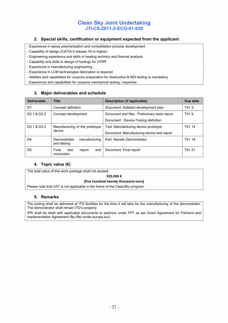
2. Special skills, certification or equipment expected from the applicant - Experience in epoxy polymerization and consolidation process development - Capability of design (CATIA 5 release 16 or higher) - Engineering experience and skills in heating technics and thermal analysis - Capability and skills in design of toolings for CFRP - Experience in manufacturing engineering , - Experience in LCM technologies fabrication is required - Abilities and capabilities for coupons preparation for destructive & NDI testing is mandatory - Experience and capabilities for coupons mechanical testing / expertise
3. Major deliverables and schedule
Deliverable Title Description (if applicable) Due date
D1 Concept definition Document: Detailed development plan T0+ 3
D2.1 & D2.2 Concept development Document and files : Preliminary tests report
Document : Device-Tooling definition
T0+ 9
D3.1 & D3.2 Manufacturing of the prototype device
Tool: Manufacturing device prototype
Document: Manufacturing device test report
T0+ 14
D4 Demonstrator manufacturing and testing
Part: Nacelle Demonstrator T0+ 18
D5 Final test report and conclusion
Document: Final report T0+ 21
4. Topic value (€) The total value of this work package shall not exceed:
520,000 € [five hundred twenty thousand euro]
Please note that VAT is not applicable in the frame of the CleanSky program.
5. Remarks The tooling shall be delivered at ITD facilities for the time it will take for the manufacturing of the demonstrator. The demonstrator shall remain ITD’s property. IPR shall be dealt with applicable documents to partners under FP7 as per Grant Agreement for Partners and Implementation Agreement (ftp://ftp.cordis.europa.eu/).

Clean Sky Joint Undertaking
JTI-CS-2011-2-ECO-01-031
- 22 -
CfP topic number Title
End date T0 + 25 JTI-CS-2011-2-ECO-01-031 Green integrated polyurethane foams with improved fire resistance for airliner seat cushions
Start date T0
1. Topic Description The objective is to develop design and production of sustainable a/c seating cushion. This includes
- transfer novel bio based PU foam formulation in technical PU processing (back injection foaming or alternative block foaming): one formulation test series (lab scale for different formulation ingredients like biobased polyol and other additives), a second series for evaluating the results on pilot plant level
- develop an ergonomic design of a/c seating cushion. Relevant parameters are hardness and comfort parameters according to DIN EN 3386-1 and 2439, surface interface pressure between user and cushion based on body pressure measurement system (BPMS).
- perform two test series (lab and pilot plant scale) to development of processing technology for PU processing foaming with flame retardant additives for light weight seat cushions
- perform characterisation of foams: mechanical properties according to EN 845 (density); EN 3386-1 (hardness load deflection); EN 2439 (indentation hardness), 1798 (mechanical strength); EN 1856 (compression set), EN 3385 (dynamic fatigue test) and flame resistance according to FAR 24.853B, FAR 24.853C and ABD 0031 and finally
- produce demonstrator seating cushions and test one prototype on in-flight condition level and/or run dynamic fatique tests according EN 3385; check comfort using BPMS after dynamic fatique stress test
- produce PU foams with recycling polyols from biobased PU foams (Recycling of PU foam waste)
- perform confection of demonstrator seat cushions with textile and belts
To apply for the call the applicant shall: - demonstrate its expertise in production of PU seat cushion material (for aviation) - provide adequate knowledge for ergonomic design seat cushion material - demonstrate that their background on the application of renewable resource and non halogen flame retardants in PUR formulation and foaming technology in on a high level - demonstrate that their involvement in flame retardance testing and application of cushion materials used in public transport applications on international level is significant
2. Special skills, certification or equipment expected from the applicant Expertise in production PU cushion material for aerospace applications Management of polyurethane in house foam formulation and foaming technology, knowledge about use of
renewable polyols in foam production Good knowledge for ergonomic standards design of seating cushion Expertise in flammability standardisation of cushion materials and fire testing equipment Equipment for testing physical properties of cushions (as compression, durability, …) and small burning
Clean Sky Joint Undertaking
JTI-CS-2011-2-ECO-01-031
- 23 -
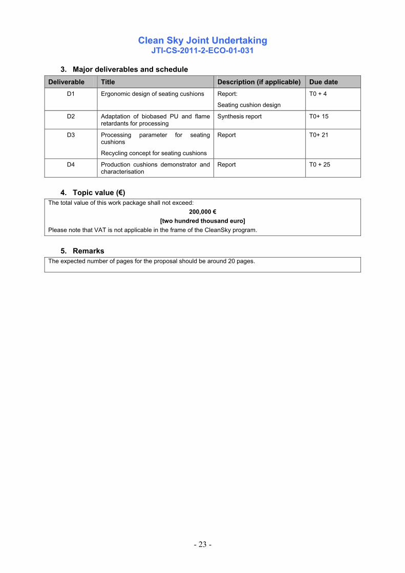
3. Major deliverables and schedule Deliverable Title Description (if applicable) Due date
D1 Ergonomic design of seating cushions Report:
Seating cushion design
T0 + 4
D2 Adaptation of biobased PU and flame retardants for processing
Synthesis report T0+ 15
D3 Processing parameter for seating cushions
Recycling concept for seating cushions
Report
T0+ 21
D4 Production cushions demonstrator and characterisation
Report T0 + 25
4. Topic value (€)
The total value of this work package shall not exceed: 200,000 €
[two hundred thousand euro] Please note that VAT is not applicable in the frame of the CleanSky program.
5. Remarks The expected number of pages for the proposal should be around 20 pages.

Clean Sky Joint Undertaking
Call SP1-JTI-CS-2011-02 Green Regional Aircraft
- 24 -
Clean Sky – Green Regional Aircraft
Identification topics VALUE MAX FUNDJTI-CS-GRA 3 1.835.000 1.376.250JTI-CS-GRA-01 185.000
JTI-CS-2011-2-GRA-01-038 185.000JTI-CS-GRA-02JTI-CS-GRA-03 1.650.000
JTI-CS-2011-2-GRA-03-004 900.000JTI-CS-2011-2-GRA-03-005 750.000
JTI-CS-GRA-04JTI-CS-GRA-05
Area-03 - All electric aircraft
Area-04 - Mission and trajectory ManagementDesign, development and manufacturing of EMA and Test Set-up for advanced Landing Gear System actuation
ITD - AREA - TOPICClean Sky - Green Regional Aircraft
Design, manufacturing and impact test on selected panels with advanced composite materialArea-01 - Low weight configurations
Area-02 - Low noise configurations
Advanced Flight Control System – Design, Development and Manufacturing of an Electro Mechanical Actuator
Area-05 - New configurations
Clean Sky Joint Undertaking
JTI-CS-2011-2-GRA-01-038
- 25 -
Topic Description
CfP topic number Title
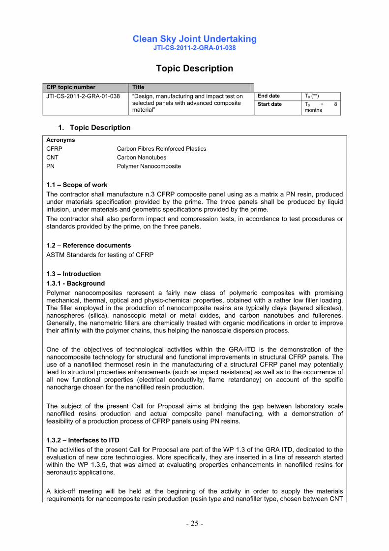
End date T0 (**) JTI-CS-2011-2-GRA-01-038 “Design, manufacturing and impact test on selected panels with advanced composite material”
Start date T0 + 8 months
1. Topic Description Acronyms CFRP Carbon Fibres Reinforced Plastics CNT Carbon Nanotubes PN Polymer Nanocomposite 1.1 – Scope of work The contractor shall manufacture n.3 CFRP composite panel using as a matrix a PN resin, produced under materials specification provided by the prime. The three panels shall be produced by liquid infusion, under materials and geometric specifications provided by the prime. The contractor shall also perform impact and compression tests, in accordance to test procedures or standards provided by the prime, on the three panels. 1.2 – Reference documents ASTM Standards for testing of CFRP 1.3 – Introduction 1.3.1 - Background Polymer nanocomposites represent a fairly new class of polymeric composites with promising mechanical, thermal, optical and physic-chemical properties, obtained with a rather low filler loading. The filler employed in the production of nanocomposite resins are typically clays (layered silicates), nanospheres (silica), nanoscopic metal or metal oxides, and carbon nanotubes and fullerenes. Generally, the nanometric fillers are chemically treated with organic modifications in order to improve their affinity with the polymer chains, thus helping the nanoscale dispersion process. One of the objectives of technological activities within the GRA-ITD is the demonstration of the nanocomposite technology for structural and functional improvements in structural CFRP panels. The use of a nanofilled thermoset resin in the manufacturing of a structural CFRP panel may potentially lead to structural properties enhancements (such as impact resistance) as well as to the occurrence of all new functional properties (electrical conductivity, flame retardancy) on account of the spcific nanocharge chosen for the nanofilled resin production. The subject of the present Call for Proposal aims at bridging the gap between laboratory scale nanofilled resins production and actual composite panel manufacting, with a demonstration of feasibility of a production process of CFRP panels using PN resins. 1.3.2 – Interfaces to ITD The activities of the present Call for Proposal are part of the WP 1.3 of the GRA ITD, dedicated to the evaluation of new core technologies. More specifically, they are inserted in a line of research started within the WP 1.3.5, that was aimed at evaluating properties enhancements in nanofilled resins for aeronautic applications. A kick-off meeting will be held at the beginning of the activity in order to supply the materials requirements for nanocomposite resin production (resin type and nanofiller type, chosen between CNT
Clean Sky Joint Undertaking
JTI-CS-2011-2-GRA-01-038
- 26 -
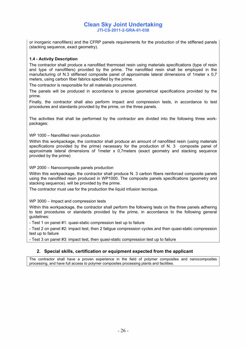
or inorganic nanofillers) and the CFRP panels requirements for the production of the stiffened panels (stacking sequence, exact geometry). 1.4 - Activity Description The contractor shall produce a nanofilled thermoset resin using materials specifications (type of resin and type of nanofillers) provided by the prime. The nanofilled resin shall be employed in the manufacturing of N.3 stiffened composite panel of approximate lateral dimensions of 1meter x 0,7 meters, using carbon fiber fabrics specified by the prime. The contractor is responsible for all materials procurement. The panels will be produced in accordance to precise geometrical specifications provided by the prime. Finally, the contractor shall also perform impact and compression tests, in accordance to test procedures and standards provided by the prime, on the three panels. The activities that shall be performed by the contractor are divided into the following three work-packages: WP 1000 – Nanofilled resin production Within this workpackage, the contractor shall produce an amount of nanofilled resin (using materials specifications provided by the prime) necessary for the production of N. 3 composite panel of approximate lateral dimensions of 1meter x 0,7meters (exact geometry and stacking sequence provided by the prime) WP 2000 – Nanocomposite panels production Within this workpackage, the contractor shall produce N. 3 carbon fibers reinforced composite panels using the nanofilled resin produced in WP1000. The composite panels specifications (geometry and stacking sequence). will be provided by the prime. The contractor must use for the production the liquid infusion tecnique. WP 3000 – Impact and compression tests Within this workpackage, the contractor shall perform the following tests on the three panels adhering to test procedures or standards provided by the prime, in accordance to the following general guidelines: - Test 1 on panel #1: quasi-static compression test up to failure - Test 2 on panel #2: impact test, then 2 fatigue compression cycles and then quasi-static compression test up to failure - Test 3 on panel #3: impact test, then quasi-static compression test up to failure
2. Special skills, certification or equipment expected from the applicant The contractor shall have a proven experience in the field of polymer composites and nanocomposites processing, and have full access to polymer composites processing plants and facilities.

Clean Sky Joint Undertaking
JTI-CS-2011-2-GRA-01-038
- 27 -
3. Major deliverables and schedule Deliverable Title Description (if applicable) Due date
Del.1 Nanofilled resin production report
Within this technical report, full details on the production of the nanocomposite resin to be used as a matrix in the realization of the composite panel shall be provided (dispersion method, handling procedures, etc).
T0 + 5
Del. 2 Composite panels manufacturing report
Within this technical report, full details on the production of the composite panels shall be provided (process parameters, critical aspects, quality concerns, ecc)
T0 + 7
Del. 3 Composite panels 3 composite panels with a nanofilled matrix T0 + 8 Del. 4 Impact and
compression test report Within this technical report, the results of the impact and comprssion tests performed on the three panels shall be reported and critically discussed.
T0 + 8
4. Topic value (K€)
Budget: The Maximum Allowed Topic Budget is
185.000,00 €
[one hundred eighty five thousand Euro]
The maximum funding value is between 50% and 75% of the Maximum Allowed Topic Budget indicated above according to the CfP rules.
Please note that VAT is not applicable in the frame of the CleanSky programme
5. Remarks The activity will be monitored by mean of bi-monthly meetings that will be held alternatively at the prime’s or the contractor’s premises. Within each of these meetings, a progress report shall be delivered by the contractor.

Clean Sky Joint Undertaking
JTI-CS-2011-2-GRA-03-004
- 28 -
Topic description
CfP topic number Title
Start date T0 JTI-CS-2011-2-GRA-03-004 Advanced Flight Control System – Design, Development and Manufacturing of an Electro Mechanical Actuator with associated Electronic Control Unit and dedicated Test Bench.
End date T0 + M48
Abbreviation List
AC Alternate Current A/C Aircraft AEA All Electric Aircraft AFCS Advanced Flight Control System ATR Acceptance Test Report CBIT Continuous Built In Test CfP Call for Proposal DC Direct Current DDP Declaration of Design and Performance ECU Electronic Control Unit E-EM Electrical Energy Management EMA Electro-Mechanical Actuator EMACS Electro-Mechanical Actuator Command System EMC Electro Magnetic Compatibility EMI Electro Magnetic Interference EPGDS Electrical Power Generation and Distribution System FCC Flight Control Computer FCS Flight Control System GRA Green Regional Aircraft GUI Graphical User Interface ITD Integrated Technology Demonstrator JTI Joint Technology Initiative PBIT Power-up Built In Test
1. Topic Description CFP SHORT DESCRIPTION
The Green Regional Aircraft is a concept design intended to replace any non-electrically powered system to the maximum extent possible and focusing towards “oil-less power by wire aircraft” to reduce the impact of aviation on the environment. In accordance with such a philosophy, it is required to study an Advanced Flight Control System architecture based on a redundant configuration with Electro-Mechanical Actuators to command both the Primary and Secondary flight control surfaces of a Regional Transport Aircraft. Therefore it is important to take into account the possibility to employ an Electro-Mechanical Actuator and its associated digital Electronic Control Unit for a Primary Flight Controls role in a future All Electric Aircraft into Green Regional Aircraft program. For the above depicted scenario, the CfP main objectives are:
1 to design, develop and manufacture the EMA and its ECU, suitable for an FCS application
2 to design, develop and manufacture a Test Bench (suitable to integrate and test the EMA and ECU) with associated counter load and the inertial load simulation systems.
3 to perform a dedicated testing activity in order to verify and validate the EMA and Test Bench

Clean Sky Joint Undertaking
JTI-CS-2011-2-GRA-03-004
- 29 -
performance
After delivery, the EMA and Test Bench will be used for on ground electrical test rig campaign on COPPER Bird® facility at Hispano-Suiza premises, and also installed in a dedicated compartment area of an ATR72 aircraft for GRA AEA in-flight demonstration. INTRODUCTION
The aim of this topic is to design, develop and manufacture
1. an EMA and its digital Electronic Control Unit (ECU), and
2. a Test Bench to integrate and test the EMA and ECU.
For these reasons it is necessary to develop a Test Bench with counter-load and inertial loads simulation systems, and able to simulate different values of structure stiffness within a predefined range. Furhter details will be provided as an input by CfP topic manager at starting of the activity and during development phase. The counter-load system will be used to simulate the aerodynamic loads opposing to the commands performed by the EMA. Moreover, the effect of the inertial loads insisting on each EMA will be simulated by means of a mass-balance system. Test Bench Command System (EMACS) shall generate the EMA and ECU control commands (e.g., all controls and time histories of commands) and record their performance (e.g., ram displacement, applied loads, currents, etc.). Based on a preliminary assessment it has been decided to study an actuation control system for the Rudder surface of the GRA, considering it as the most demanding application in terms of loads required for a safe and reliable flight control system. DETAILED DESCRIPTION EMA DESIGN REQUIREMENTS
Power supply The EMA shall be supplied by Electrical Power Generation Systems at 270 VDC.
Equipment Architecture The following requirements are meant to design the EMA and its associated ECU as much reliable as possible for a Rudder control surface actuation system.
• Linear type electro-mechanical actuator, Single electric motor architecture, controlled by means of a programmable digital Electronic Control Unit,
• EMA position dual sensor,
• Fail-Safe design, defined as a reversible-type actuator able to follow aerodynamic stream with pre-defined damping. An anti-jamming device must be included to prevent the actuator jamming in case of mechanical failure of the EMA.
• Two communication channels towards Flight Control Computers (FCCs) control.
• EMA no-load actuation rate shall be approximately 140 mm/sec.
• EMA stall load shall be within the range 44.000 N – 50.000 N,
• EMA shall be sized to react a continuos load not less than 35.000 N,
• EMA shall be sized to provide a continuos power 2,5 kW,
• Position Frequency Response at ±1mm actuator displacement:
phase lag: > -12 deg @ 1Hz, > -45 deg @ 5Hz
gain > - 3dB @ 5Hz
• Stability Margin: gain margin 6 dB, phase margin 45 deg,
• The actuator static stiffness shall be higher than 60.000 N/mm.

Clean Sky Joint Undertaking
JTI-CS-2011-2-GRA-03-004
- 30 -
• An internal Built In Test, comprising both a Power-up BIT and a Continuous BIT, shall be implemented within the ECU with self-monitoring capability. Further details will be agreed before and during the development activity.
• A programmable digital control loop shall be implemented within the ECU, by means of a suitable user interface.
• The ECU shall allow an electronic rigging capability of the actuator stroke.
• A mathematical model, compatible with Matlab/Simulink™ and SABER™ tools, shall be delivered for numerical simulation purposes within GRA program.
Internal stops The EMA shall be equipped with mechanical stops to prevent exceeding the required total mechanical stroke, and they shall be capable to withstand the bottoming load. In no case the mechanical stops may cause the jamming of the actuator. The EMA electrical travel shall be limited electronically within the servo-loop control laws.
Electrical Connections BASIC AIRCRAFT CONNECTORS MIL-C-26482G Serie II class L (P/N's MS3475W10-6PW and MS3475W10-6PN).
Pin allocation will be agreed with the applicant during the development phase.
Mechanical Interface The EMA shall be integrated on the dedicated test bench, and stimulated also by means of the test bench counter load systems. The attachment shall be obtained by means of a spherical bearing inside the eye-end in order to allow the EMA to oscillate along its longitudinal axis. Actuator design shall comply with the following requirements:
- Actuator working stroke = 150 mm
- Total (mechanical) actuator stroke = 160 mm
Rigging Rigging procedure shall be defined according to the tolerances defined in the actuator unit drawings.
Mass The maximum mass of the EMA, including ECU, shall not exceed 16 kg.
Power Consumption The maximum electrical power input shall be less than 3,3 KW.
Reliability The EMA MTBF shall be not less than 10.000 O.H.
TEST BENCH DESIGN REQUIREMENTS
Test Bench Architecture The following requirements are meant to design the Test Bench and its associated counter load and inertial load simulation systems as simple and reliable as possible to incorporate the EMA and its ECU. It is necessary to take into account that the entire test rig shall be installed also on a demo aircraft for a flight test and therefore the mass and the overall dimensions shall be minimized. The test bench shall incorporate:
• A counter-load system (an Hydraulic actutor would be a viable solution for the COPPER Bird® application) capable to positively stall the EMA under test;
• A stiffness and inertial-loads simulation system;

Clean Sky Joint Undertaking
JTI-CS-2011-2-GRA-03-004
- 31 -
• A Test Bench Command System to generate and record the EMA commands and performance;
• Capability of failure injection (including the capability of testing the anti-jamming device).
Test bench interfaces For qualification and COPPER Bird® ground test purposes it would be preferred a counter-load system composed by an hydraulic actuator with its own hydraulic circuit, fully integrated onto the test bench, but any other proposed architecture fulfilling the expected functions will be evaluated; the Applicant is requested to optimize the counter-load system design for being used in both testing application. The hydraulic pump shall be capable to supply the required flow rate to move the counter load actuator at the EMA maximum no-load rate and to provide the necessary power to counteract the EMA load at any EMA actuation rate. On COPPER Bird® facility the following two electrical power networks will be available to supply the EMA counter-load system, its control system and the test bench ancillaries:
• 230 VAC @ 50 Hz, and
• 400 VAC @ 50 Hz.
For the test during the Flight Demo activities will have the following electrical power network:
• a 115 VAC @ variable frequency.
No hydraulic power supply is foreseen either at COPPER Bird® rig or on flight demo aircraft.
Electrical Connections The Connectors and pin allocation will be agreed with Applicant during the development phase.
Mechanical Interface The test bench shall accommodate the EMA and its ECU so, the Test bench design and associated counter-load system shall comply with the EMA design and requirements.
Mass The maximum mass, including the simulation load system, shall be less than 250 kg.
Size Considering the need to install the rig on the demo A/C, size of the rig shall allow to boarding it. As an alternative, the rig shall be designed to be easily assembled and disassembled in order to satisfy the above said requirement.
COMPONENT ENVIRONMENTAL CONDITIONS
The Components shall meet the requirements and shall provide performance required by DO-160F. The EMA and its ECU shall be subjected to the following test in accordance with the DO-160F to show compliance to the specified requirements:
- Temperature / Altitude,
- EMC / EMI,
- Magnetic effect.
The details and the extent of these environmental tests will be agreed with the Applicant. The Applicant shall take into account the following environmental requirements for the design of the EMA and Test Bench.
The following tests are intended for EMA:
Temperature: For the EMA, DO-160F, section 4, table 4.1, Category C2 equipment temperature conditions (-55°C to

Clean Sky Joint Undertaking
JTI-CS-2011-2-GRA-03-004
- 32 -
+70°C) are applicable for continuous and short time operations. The equipment shall be capable to satisfy operations following prolonged exposure (non operating) to a -55°C to + 85°C environment. Fungus resistance The EMA shall be manufactured avoiding materials which are nutrition for fungi, whenever possible. Where this is not practicable, a suitable fungicidal agent or other means shall be used to protect materials. Fungus conditions per Section 13, Category F of DO-160F are applicable.
Vibration Vibration test category for the GRA shall be category S. MLG EMA shall refere to vibration test level T (wing and wheel well) and shall be tested according to the standard sinusoidal vibration test recalled in the DO-160F ch. 8 para 8.5. During the preliminary resonance search test, the sinusoidal sweep rate shall be limited to 0.5 octaves/minute, whenever possible. In addition, the resonance search test shall be repeated after the performance test to demonstrate that no hidden damage is the cause of a change in dynamic response.
A qualification test plan shall be foreseen by the applicant, showing which standardized tests will be performed in order to assure compatibility of the equipment with both test environments.
A minimum set of test is listed below:
(The following tests are intended for both EMA and Test Bench)
Crash Safety The equipment shall satisfy the requirements of DO-160F, Section 7. Power Quality The equipment shall satisfy the requirements of MIL-STD-704F.
EMC/EMI For the components, the requirements for EMC/EMI will be defined.
Voltage Spike For the components, the requirements for Voltage Spike will be defined. Magnetic Effect The magnetic effect of the complete equipment, classified in Category A, shall be demonstrated in accordance with the test requirements per section 15 of DO-160F. Bonding The construction of the components shall be such that metallic parts not associated with the electrical functioning of the unit, will be electrically bonded together with a maximum resistance between any two parts of 25 milliohms throughout the life of the equipment. It is allowed a derogation for movable part. Fluids susceptibility The equipment shall satisfy the requirements of DO-160F, section 11, category F.
Non combustibility All materials employed in the components manufacturing shall not promote combustion, or – in the event of fire – the materials shall not sustain or support combustion.
Consummable and wearing parts Component batch shall provide wearing parts (such as filters, gaskets, etc.) in the appropriate quantities to satisfy the test campaign constraints and schedule.
Clean Sky Joint Undertaking
JTI-CS-2011-2-GRA-03-004
- 33 -
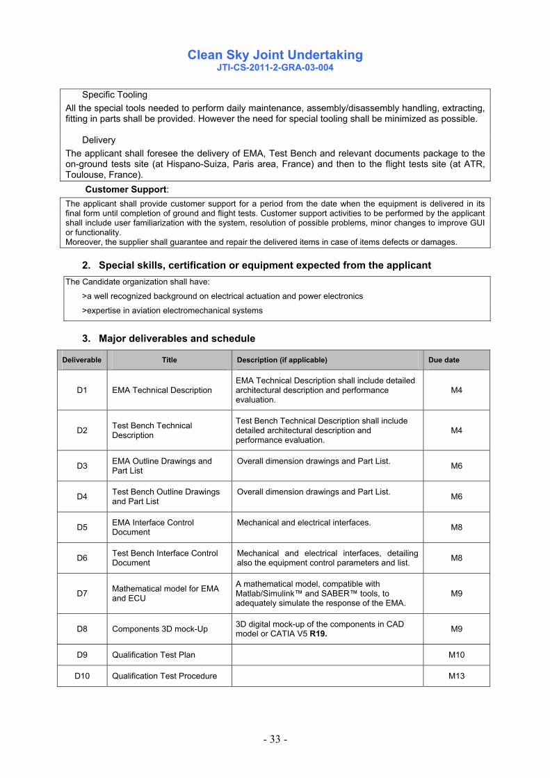
Specific Tooling All the special tools needed to perform daily maintenance, assembly/disassembly handling, extracting, fitting in parts shall be provided. However the need for special tooling shall be minimized as possible. Delivery The applicant shall foresee the delivery of EMA, Test Bench and relevant documents package to the on-ground tests site (at Hispano-Suiza, Paris area, France) and then to the flight tests site (at ATR, Toulouse, France).
Customer Support: The applicant shall provide customer support for a period from the date when the equipment is delivered in its final form until completion of ground and flight tests. Customer support activities to be performed by the applicant shall include user familiarization with the system, resolution of possible problems, minor changes to improve GUI or functionality. Moreover, the supplier shall guarantee and repair the delivered items in case of items defects or damages.
2. Special skills, certification or equipment expected from the applicant The Candidate organization shall have:
>a well recognized background on electrical actuation and power electronics
>expertise in aviation electromechanical systems
3. Major deliverables and schedule
Deliverable Title Description (if applicable) Due date
D1 EMA Technical Description EMA Technical Description shall include detailed architectural description and performance evaluation.
M4
D2 Test Bench Technical Description
Test Bench Technical Description shall include detailed architectural description and performance evaluation.
M4
D3 EMA Outline Drawings and Part List
Overall dimension drawings and Part List. M6
D4 Test Bench Outline Drawings and Part List
Overall dimension drawings and Part List. M6
D5 EMA Interface Control Document
Mechanical and electrical interfaces. M8
D6 Test Bench Interface Control Document
Mechanical and electrical interfaces, detailing also the equipment control parameters and list. M8
D7 Mathematical model for EMA and ECU
A mathematical model, compatible with Matlab/Simulink™ and SABER™ tools, to adequately simulate the response of the EMA.
M9
D8 Components 3D mock-Up 3D digital mock-up of the components in CAD model or CATIA V5 R19. M9
D9 Qualification Test Plan M10
D10 Qualification Test Procedure M13

Clean Sky Joint Undertaking
JTI-CS-2011-2-GRA-03-004
- 34 -
Deliverable Title Description (if applicable) Due date
D11 Operating instruction manuals The assembly, disassembly, maintenance and functional components manual and sensors calibration data and description sheet.
M14
D12 Components Final Test Report, ATR and DDP.
Final summary report, Acceptance Test Report and Declaration of Design and Performance. M16
D13 n.1 EMA and n.1 Test Bench deliveries
1st Delivery at Hispano-Suiza, Paris area, France
2nd Delivery at ATR Toulouse, France
The documentation needed for using EMA and test rig during test campaigns shall be part of EMA and Test rig delivery. As minimum this documentation shall contain: Operating instructions manual; Basic maintenance manual; Sensor calibration and description sheet;
Part list and associated assembly drawing;
M16
M26
D14 Support During assembly and Test Activities (whenever required) until completion of testing activities. M48
4. Topic value (€)
The Maximum Allowed Topic Budget is
900.000,00 €
[Nine hundred thousand Euro]
The maximum funding value is between 50% and 75% of the Maximum Allowed Topic Budget indicated above according to the CfP rules.
Please note that VAT is not applicable in the frame of the CleanSky programme
5. Remarks
None.

Clean Sky Joint Undertaking
JTI-CS-2011-2-GRA-03-005
- 35 -
Topic description
CfP topic number Title
Start date T0 JTI-CS-2011-2-GRA-03-005 Design, development and manufacturing of EMA and Test Set UP for advanced Landing Gear System actuation.
End date T0+48
Abbreviation List AC Alternate Current A/C Aircraft AEA All Electric Aircraft ATR Avions de Trasport Regional BIT Built In Test CfP Call for Proposal CS Certification Specifications DC Direct Current ECU Electronic Control Unit EDS Eco Design for Systems EMA Electro-Mechanical Actuator GRA Green Regional Aircraft ITD Integrated Technology Demonstrator LG Landing Gear MLG Main Landing Gear
1. Topic Description CFP SHORT DESCRIPTION
The Green Regional Aircraft (GRA) is a concept design aimed to replace any non-electrically powered system with an electrical one.
Within the Clean Sky GRA ITD, the design and analysis of a complete All-Electric Aircraft (AEA) is on going.
Particularly, moving towards a Green and innovative Regional Aircraft on which the only power source will be the electrical one, all loads that traditionally are hydraulically powered must be re-designed.
In accordance with that, a complete all-electric landing gear actuation system is under study as well.
The most important targets of this studies are the verification of:
- The compliancy of this system to the main applicable performance and certification requirements;
- The electrical power demand during the whole actuation phase of such system;
The most demanding device with respect to the above mentioned issues is the Main Landing Gear (MLG) actuator.
The aim of this Call for Proposal is:
- Designing and manufacturing a MLG Electro-Mechanical Actuator (EMA) and its dedicated Electronic Control Unit (ECU) for a future All-Electric Regional Aircraft configuration;
- Testing the MLG EMA in order to verify its main characteristics and performance;
- Designing and manufacturing a dedicated test rig to be used for:
- installing the MLG EMA on the Aircraft (A/C) and using it for GRA in-flight test as actual electric load;
Clean Sky Joint Undertaking
JTI-CS-2011-2-GRA-03-005
- 36 -
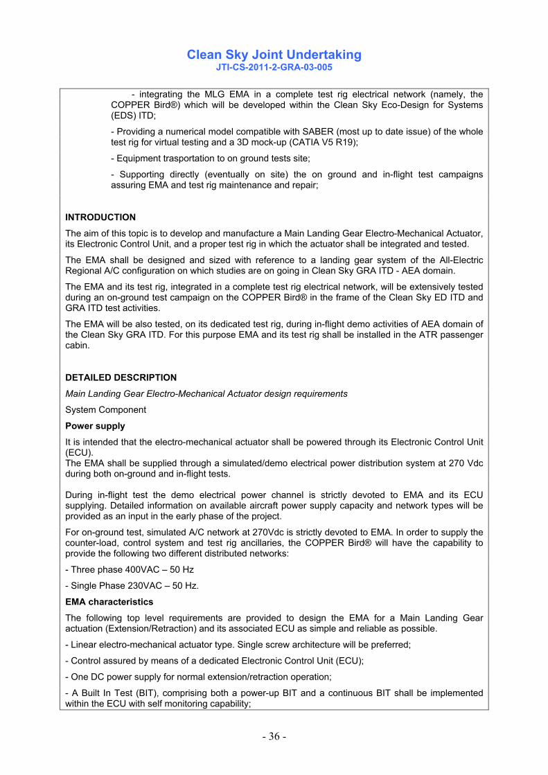
- integrating the MLG EMA in a complete test rig electrical network (namely, the COPPER Bird®) which will be developed within the Clean Sky Eco-Design for Systems (EDS) ITD;
- Providing a numerical model compatible with SABER (most up to date issue) of the whole test rig for virtual testing and a 3D mock-up (CATIA V5 R19);
- Equipment trasportation to on ground tests site;
- Supporting directly (eventually on site) the on ground and in-flight test campaigns assuring EMA and test rig maintenance and repair;
INTRODUCTION
The aim of this topic is to develop and manufacture a Main Landing Gear Electro-Mechanical Actuator, its Electronic Control Unit, and a proper test rig in which the actuator shall be integrated and tested.
The EMA shall be designed and sized with reference to a landing gear system of the All-Electric Regional A/C configuration on which studies are on going in Clean Sky GRA ITD - AEA domain.
The EMA and its test rig, integrated in a complete test rig electrical network, will be extensively tested during an on-ground test campaign on the COPPER Bird® in the frame of the Clean Sky ED ITD and GRA ITD test activities.
The EMA will be also tested, on its dedicated test rig, during in-flight demo activities of AEA domain of the Clean Sky GRA ITD. For this purpose EMA and its test rig shall be installed in the ATR passenger cabin.
DETAILED DESCRIPTION
Main Landing Gear Electro-Mechanical Actuator design requirements
System Component
Power supply
It is intended that the electro-mechanical actuator shall be powered through its Electronic Control Unit (ECU). The EMA shall be supplied through a simulated/demo electrical power distribution system at 270 Vdc during both on-ground and in-flight tests. During in-flight test the demo electrical power channel is strictly devoted to EMA and its ECU supplying. Detailed information on available aircraft power supply capacity and network types will be provided as an input in the early phase of the project.
For on-ground test, simulated A/C network at 270Vdc is strictly devoted to EMA. In order to supply the counter-load, control system and test rig ancillaries, the COPPER Bird® will have the capability to provide the following two different distributed networks:
- Three phase 400VAC – 50 Hz
- Single Phase 230VAC – 50 Hz.
EMA characteristics
The following top level requirements are provided to design the EMA for a Main Landing Gear actuation (Extension/Retraction) and its associated ECU as simple and reliable as possible.
- Linear electro-mechanical actuator type. Single screw architecture will be preferred;
- Control assured by means of a dedicated Electronic Control Unit (ECU);
- One DC power supply for normal extension/retraction operation;
- A Built In Test (BIT), comprising both a power-up BIT and a continuous BIT shall be implemented within the ECU with self monitoring capability;

Clean Sky Joint Undertaking
JTI-CS-2011-2-GRA-03-005
- 37 -
- EMA shall feature “end stroke” devices to control Up lock and Down lock position of the MLG;
- EMA shall be capable to perform a complete extension and retraction manoeuvres in a time not greater than 10 seconds for each;
A preliminary estimation of the design load which the EMA shall be capable of extend / retract is in the order of magnitude of about 100kN;
Final figure of this value will be provided in the early stage of the project;
Detailed load curves will be provided to allow EMA test procedures issue;
In order to assure the full separation between normal ext/ret system and emergency extension functions, EMA shall comply with the following requirements.
- EMA design shall be such that no single electrical failure (power and control) will prevent the actuator emergency extension;
- In case of any single mechanical failure (non-structural), emergency extension of the EMA shall be assured;
To assure extension by gravity, a mechanical device for EMA release from retracted position shall be designed;
The proposal of a Health Monitoring system for mechanical parts failure detection and/or prediction will constitute a preference in the proposal evaluation process;
The EMA shall be capable to perform a complete emergency extension manoeuvre in a time not greater than 15 seconds; Technological issue not allowing this requirement compliance shall be discussed with Topic Manager;
In general, Civil Certification requirements (CS 25) applicable to a LG actuation system shall be used as reference when and if applicable.
EMA test rig requirements
The EMA, object of this CfP, will be used for several tests that will be performed in two different test activities.
The first one will concern the MLG EMA test rig integration in a complete test rig electrical network that will be reproduced on-ground (COPPER Bird®, activity relevant to Clean Sky ED ITD and GRA ITD).
Then the EMA installed on its dedicated test rig will be also tested during in-flight demo activities of AEA domain of the Clean Sky GRA ITD. In this case the EMA and its test rig shall be installed in the ATR passenger cabin.
Detailed mechanical and electrical interface requirements for both test activities will be provided as an input in the early stage of the project.
For what said above, EMA test rig shall include (but shall not be limited to) the following technical features for testing the actuator:
- EMA and test rig control system;
- EMA and test rig control panel by means of shall be possible to command actuator operation and monitor its main functional parameters;
- Inertia load or any other mean to simulate the MLG leg weight for emergency extension capability;
- A dedicated electrical interface for data exchange relevant to monitored parameters;
- Counter-load actuator and its own power supply system;
For qualification/acceptance and on-ground tests the counter-load shall be capable to simulate specific load curves provided by Topic Manager. An hydraulic actuator with its own hydraulic power generation and distribution circuit fully integrated into the test rig is preferred but any other proposed architecture fulfilling the expected functions will be evaluated;
A technical trade-off is in progres to establish if an hydraulic counter-load system is feasible for in-flight tests. Should it be not feasible, a dedicated fully mechanical counter load system (e.g. springs)

Clean Sky Joint Undertaking
JTI-CS-2011-2-GRA-03-005
- 38 -
shall be designed; The load profile shall be agreed between selected applicant and Topic Manager;
Supplier is requested to optimize the counter-load system design for both testing application;
EMA test rig shall allow data and signals exchange with the COPPER Bird® and A/C control and command system.
EMA test rig can be operated in:
- “local” mode through its own control panel;
- “remote” mode through COPPER Bird® and A/C control and command system;
Information on mechanical interface for EMA test rig installation on aircraft for in-flight test demo activities will be provided.
A dedicated procedure and any necessary special tools shall be provided in order to allow test rig assembly on the aircraft.
Equipment test requirements
The following qualification test activity shall be conducted, as minimum, in order to demostrate EMA compliance with Landing Gear actuation system performance and functionality and assure a sufficient safety of flight level, necessary to allow EMA in-flight test demo application as electrical load.
The selected applicant shall provide an acceptance test plan detaling the demonstrations of EMA (and its test rig, if applicable) performance. These tests shall include at least, actuator load capability, static strength, electrical starting and operating current characteristics. An endurance test shall be foreseen with the main objectives to show that the MLG EMA shall be able to operate correctly under specific loading conditions for a number of cycles.
Dedicated tests must be included to demonstrate emergency extension function.
Moreover the following tests will be proposed:
1. Extreme temperature tests: Compliance with operating high/low temperature shall be demostrated as per DO-160F ch. 4 para. 4.5.4/4.5.2. (equipment category B2).
2. Vibration: Vibration test category for the GRA shall be category S. MLG EMA shall refere to vibration test level T (wing and wheel well) and shall be tested according to the standard sinusoidal vibration test recalled in the DO-160F ch. 8 para 8.5. During the preliminary resonance search test, the sinusoidal sweep rate shall be limited to 0.5 octaves/minute, whenever possible. In addition, the resonance search test shall be repeated after the performance test to demonstrate that no hidden damage is the cause of a change in dynamic response.
A qualification test plan shall be foreseen by the applicant, showing which standardized tests will be performed in order to assure compatibility of the equipment with both test environments.
A minimum set of test is listed below:
(The following tests are relevant to EMA and Test rig)
1. Power Input: as per MIL-STD-704F. The applicable test methods of MIL-HDBK-704 shall be used.
2. Voltage Spike: The applicable test procedure and requeriments shall be agreed between Topic Manager and the selected partner.
3. Shock: The equipment shall demonstrate compliance with the requirements for crash safety shock category, by test, performed according to DO-160F ch. 7, para. 7.3.
4. Constant Acceleration (Crash): Detailed requirements concerning this test shall be provided in the early phase of the project. These will be specified in accordance with CS 25.561.
5. Magnetic effect: as per DO-160F ch. 15.
6. Electrostatic discharge: as per DO-160F ch. 25, para 25.5.
7. Emission of Radio Frequency Energy: as per DO-160F ch. 21. The equipment category is M. Confirmation of such category applicability will be provided after on A/C installation location definition.

Clean Sky Joint Undertaking
JTI-CS-2011-2-GRA-03-005
- 39 -
Parameters to monitor
The following parameters shall be monitored as minimum and made available at the dedicated electrical interface during the tests:
Electrical power absorption
Actuator stroke/position
Actuator speed
Load
Actuator failure indication (coming from BIT)
Temperature (Motor and ECU)
Weight
Considered the purpose of the CfP items, the applicant is requested to put particular attention to EMA weight with respect to the state-of-the-art technology. Therefore any technological improvement aimed to weight saving shall be taken into account.
Estimation of the Test Rig and EMA weight figures shall be provided to Topic Manager at the proposal stage for evaluation.
Delivery, Maintenance and Repair
The applicant shall foresee the delivery of equipment to the on-ground tests site (at Hispano-Suiza, Paris area, France) and then to the flight tests site (at ATR, Toulouse, France).
Because testing at system level both on COPPER Bird® electrical test rig and GRA flight test involves a large number of components and suppliers, the applicant shall provide maintenance and technical support on its own equipment for the duration of the tests (which are scheduled until the end of 2015). The equipment of the applicant will only be handled by qualified professionnals of the ED and GRA consortia. Daily maintenance (normal care which would be performed by the crew or the lineman on an aircraft, and would not require an aircraft mechanic certificate) will normally be performed by EDS test rig operator or GRA flight test operator. The expected number of hours of operation should not require further normal maintenance.
All the special tools needed to perform daily maintenance, assembly/disassembly of the equipment shall be provided by the applicant.
Equipment supplier shall provide wearing parts in the appropriate quantities to satisfy tests campaign constraints and schedule.
Life requirements
The equipment shall be designed to have a minimum life of 2000 hours (with a scatter factor of at least 3) to accomplish both in-flight and on-ground test campaign.
Justification analysis shall be provided to show that the design is capable of meeting the life requirements.
Others
A Preliminary Design Review (T0 + 5M) and a Critical Design Review (T0 + 9M) meetings shall be held. At PDR the equipment interfaces and the performance requirements will be frozen. Whilst at the CDR the detailed design of all components will be frozen with the agreement of the Topic Manager.
From a design point of view, the proposal should be detailed including validation and justification of the selected choices/solutions.
Reference to already existing applications are welcome as illustrations.
2. Special skills, certification or equipment expected from the applicant

Clean Sky Joint Undertaking
JTI-CS-2011-2-GRA-03-005
- 40 -
The Candidate organization shall have: • a well recognized background on electrical actuation and power electronics; • experience in aircraft landing gear actuation system and its certification requirement is an asset;
3. Major deliverables and schedule Deliverable Title Description (if applicable) Due date
D1 EMA and Test Rig design requirements
This document will contain EMA and Test Rig requirements necessary, as input, for CfP activities start.
T0 + 3M
D2 EMA and Test Rig Drawings
A preliminary issue available by T0 + 4M T0 + 8M
D3 EMA and Test Rig Interface Control
Document A preliminary issue available by T0 + 4M T0 + 8M
D4 EMA and Test Rig description document A preliminary issue available by T0 + 4M T0 + 8M
D5 Qualification Test Plan A preliminary issue available by T0 + 5M T0 + 9M
D6 Qualification Test Procedure A preliminary issue available by T0 + 5M T0 + 9M
D7 Virtual model and 3D mock-up final issue
Preliminary 3D mock-up issue available by T0+4M T0 + 12M
D8 Qualification Test Report This document shall include the Acceptance Test Report T0 + 16M
D9 Declaration of Design and Performance T0 + 16M
D10 n.1 EMA and n.1 test rig deliveries
1st Delivery at Hispano-Suiza, Paris area, France
2nd Delivery at ATR Toulouse, France The documentation needed for using EMA and test rig during test campaigns shall be part of EMA and Test rig delivery. As minimum this documentation shall contain: Operating instructions manual; Basic maintenance manual; Sensor calibration and description sheet; Part list and associated assembly drawing;
T0 + 16M
T0 + 26M
D11 Support During assembly and test activities (whenever required) until completion of testing activities. T0 + 48M

Clean Sky Joint Undertaking
JTI-CS-2011-2-GRA-03-005
- 41 -
4. Topic value (€)
Budget: The Maximum Allowed Topic Budget is
750.000,00 €
[Seven hundred fifty thousand Euro]
The maximum funding value is between 50% and 75% of the Maximum Allowed Topic Budget indicated above according to the CfP rules.
Please note that VAT is not applicable in the frame of the Clean Sky programme

Clean Sky Joint Undertaking
Call SP1-JTI-CS-2011-02 Green Rotorcraft
- 42 -
Clean Sky – Green Rotorcraft
Identification topics VALUE MAX FUNDJTI-CS-GRC 3 1.230.000 922.500JTI-CS-GRC-01 800.000
JTI-CS-2011-2-GRC-01-006 500.000JTI-CS-2011-2-GRC-01-007 300.000
JTI-CS-GRC-02 JTI-CS-GRC-03 430.000
JTI-CS-2011-2-GRC-03-009 430.000JTI-CS-GRC-04JTI-CS-GRC-05 JTI-CS-GRC-06
Area-04 - Installation of diesel engines on light helicopters
Clean Sky - Green Rotorcraft
Area-06 - Eco Design for Rotorcraft
Wind Tunnel Testing of Active RotorGurney flap actuator, mechanism and control electronics for a Model scale helicopter rotor blade (Develop and su
Area-01 - Innovative Rotor Blades
Area-02 - Reduced Drag of rotorcraft
Adaptation kit design & manufacturing : APU drive
ITD - AREA - TOPIC
Area-05 - Environmentally friendly flight paths
Area-03 - Integration of innovative electrical systems

Clean Sky Joint Undertaking
JTI-CS-2011-2-GRC-01-006
- 43 -
Topic Description
CfP topic number Title End date T0+39 M
JTI-CS-2011-02-GRC-01-006 Wind Tunnel Testing of Active Rotor Start date T0
1. Topic Description
1. Background: The Green Rotorcraft Consortium (GRC 1) work described here relates to the development of Active Rotor Technologies (ART) that will enable a helicopter to operate with reduced power consumption or reduced main rotor tip speed whilst preserving current flight performance capabilities. Lower power consumption will lead to reduced fuel usage and exhaust emissions, while reduced main rotor speed will significantly reduce rotor noise. Prior tasks have evaluated a range of potential technologies that could be incorporated within active segments of a helicopter main rotor blade to meet these needs and concluded that a variable height or ‘Active Gurney Flap’ (AGF) offers the best overall potential. Conventionally a Gurney Flap is a small ‘wall’ perpendicular to the surface of the aerofoil and located in the trailing edge area of the blade, more usually on the lower blade surface. The AGF is essentially a Gurney flap with the ability to alter its height from zero (fully retracted) to maximum (fully operative). Its impact upon the performance of an aerofoil can thus be varied and controlled. On a helicopter rotor blade the aerodynamic requirements change as the blade moves around the azimuth from the blade advancing to blade retreating condition. The AGF offers the possibility of ‘conditioning’ the performance of the rotor blades to match these changing requirements by using a pre-determined schedule of operation (i.e. progressively extended/retracted) as the blade rotates around the helicopter. In order to assess the capabilities of an AGF system it is intended that system demonstrators be manufactured, trialled and evaluated. One such demonstration will be the model-scale testing of a rotor with AGFs in a suitable wind tunnel facility. To achieve these aims the Green Rotorcraft Consortium, with lead guidance provided by The Topic Manager, request bids from companies or consortiums to carry out the required wind tunnel testing of a model-scale rotor. Working with the consortium members, the successful partner will be expected to provide the wind tunnel facility, and plan and carry out the required testing. 2. Scope of work: In order to satisfy the requirements for testing GRC Innovative Rotor Blades technologies, the Green Rotorcraft Consortium members wish to engage with an organisation (or consortium) that will facilitate the testing of a model scale active rotor system. The work required from the successful organisation is: a) In conjunction with the Topic Manager and other GRC1 partners, plan the active model rotor test.
The test is currently expected to take place in 2014. For the successful bidder, the bulk of the work will happen during the test itself, but participation in the planning activity will be required from the beginning, initially at a low level.
b) The wind tunnel testing of this type of active model rotor is expected to require the development and use of novel testing techniques. The successful applicant should therefore work with the Topic Manager and other partners to define test requirements, test equipment and test methods. Novel test techniques must be developed and agreed as part of the task, and may include the use of such technologies as PIV or laser measurement as appropriate. Experience in the use of advanced measurement and imaging technologies is therefore desirable.
c) Make available a suitable wind tunnel facility for the expected duration of the test (approx. 6 weeks).

Clean Sky Joint Undertaking
JTI-CS-2011-2-GRC-01-006
- 44 -
d) Take responsibility for the operation and safety of the wind tunnel facility for the duration of the tests.
e) Provide limited advice as appropriate to assist GRC1 partners in the analysis of test results. This will include the provision of tunnel corrections, which should be applied to the measured data.
GRC1 Model Rotor Wind Tunnel Test The successful organisation will provide wind tunnel and other test facilities for the testing of a model-scale helicopter rotor with blades equipped with Active Gurney Flaps (AGF). The flaps can be deployed and retracted in a controlled manner. Tests will include hover tests, rotating rotor tests in an open-section wind tunnel and rotating rotor tests in a closed-section wind tunnel (see below for more details of the expected test conditions and rotor/rig dimensions). The objectives of the tests will be – - to evaluate the ability of the AGF system to improve the performance of the rotor system in hover and forward flight conditions - to investigate the use of the AGF system to enable rotor rotational speed (Nr) to be reduced - to investigate the effect of the AGF system on rotor dynamics and vibration - to develop a good understanding of the optimum use of the power and control systems for the AGFs Model Rotor Rig The model rotor and rig will be supplied by the GRC1 project. The leading parameters of the rotor are given below – Number of blades 4 Rotor tip diameter 2.2 m Nominal blade chord 90 mm Direction of rotation CCW viewed from top Rotational speed up to 1600 rpm Maximum rotor thrust 3500 N Maximum rotor power 170 kW Wind tunnel speed required up to 50 m/s A photograph of the model rotor rig to be used in the testing is provided in Figure 1. Based on the dimensions of the model rotor, the dimensions of the working section of the wind tunnel are required to be at least: 4 m tall x 4 m wide x 6 m long - open and closed test sections

Clean Sky Joint Undertaking
JTI-CS-2011-2-GRC-01-006
- 45 -
Tests to be Carried Out Shake Down Test – this test is intended to check the basic operation of the model rotor and active system. In the hover test facility, run the rotor over a range of speeds from 45% Nr to 100% Nr, deploying and retracting the Gurney Flaps to check the functioning of the complete system. Hover Performance Test – this test will investigate the effect of the AGF system on the hover performance of the rotor. Only steady deflections of the Gurney Flaps will be used. With the Gurney Flaps fully retracted, and deployed at three different settings up to the maximum, run the rotor at a series of speeds and applied collective pitches to measure the thrust produced and power consumed. Hover test chamber minimum requirements are 12 m tall x 12 m wide x 30 m long Forward Flight Performance Test – this test will investigate the potential benefits of the AGF system for the reduction of power consumption or rotor speed in forward flight conditions. A matrix of test points will be required, over a range of wind speeds and comprising both open-section and closed-section tests. Testing is expected to take place over a period of 6 weeks, which is currently planned to be in the second half of 2014. It is expected that the testing described will have sole use of the test facilities during this time. Instrumentation All instrumentation relating to the measurement of parameters on the model rotor will be the responsibility of the GRC1 project. The successful bidder is expected to provide measurement of the following parameters with respect to the wind tunnel itself – - wind speed - air temperature and density - tunnel static pressure - dynamic pressure Further Expectations The successful bidder, amongst other things, will be required to: - Provide full details of the Health and Safety requirements for the use of the test facilities. - Provide full details of the analysis and test requirements necessary prior to making use of the test
facilities. - Provide an Interface Control Document (ICD) fully explaining the relevant geometric, electrical
and other interfaces between the test hardware supplied by GRC1 and the test facilities. Commercial Requirements Detailed discussion of all relevant contractual requirements will take place following selection of the successful bidder. Management and protection of data transferred in support of this task is expected to be governed by a specific non-disclosure agreement (NDA), to be agreed as part of the detailed contract negotiations.

Clean Sky Joint Undertaking
JTI-CS-2011-2-GRC-01-006
- 46 -
6. Special skills, certification or equipment expected from the applicant 1. The applicant should have access to a suitable test facility able to accommodate the tests described above in
the required timeframe. 2. With regard to the proposed test facility and expertise of the applicant, bidders are expected to demonstrate
appropriate experience and knowledge of model rotor testing of the type described above. 3. The winning bidder will be expected to provide, at any stage as requested by the GRC1 project, technical
documents, drawings and descriptions of the test facilities and procedures that are necessary for the planning and execution of the tests.
7. Major deliverables and schedule Deliverable Title Short Description (if applicable) Due date (month)
M0 Contract Effective Anticipated to be January 2012, but should be sooner if possible T0
D1 Test Facility Specification Detailed specification of the test facility to support planning of model rotor tests T0 + 3 months
D2 Test Plan Contributions from successful bidder to initial test plan (and subsequent regular updates)
T0 + 6 months
D3 Report on Innovative Test Techniques
Description of new test techniques to be used as part of the active model rotor test T0 + 20 months
D4 Test Readiness Review - TRR Participation in detailed review of documentation, hardware etc. prior to start of testing
T0 + 28 months
M5 Confirm Start of Testing Currently expected in second half of 2014. T0 + 33 months M6 Confirm Completion of Testing Anticipated 6 weeks of testing T0 + 35 months D7 Report on Test Results Contribution to final report, summarising
results of active model rotor tests T0 + 38 months
8. Topic value (€) The total anticipated eligible cost of the proposal including manpower, travel costs, consumables, equipment, other direct costs, indirect costs, and subcontracting shall not exceed:
€ 500,000 (VAT not applicable) [five hundred thousand euro]
9. Remarks - All core RTD activities have to be performed by the organisation(s) submitting the proposal. If some subcontracting is included in the proposal, it can only concern external support services for assistance with minor tasks that do not represent per se project tasks. The proposal must: - indicate the tasks to be subcontracted; - duly justify the recourse to each subcontract; - provide an estimation of the costs for each subcontract. (concerning subcontracting, see provisions of the Grant Agreement Annex II.7) - The expected length of the technical proposal is 25 pages with individual chapters for each of the key
elements a) to e) defined in the scope of work. As his topic is linked to the topic JTI-CS-2011-02-GRC-01-007, aiming at designing and providing the Model scale helicopter rotor blade, ion the event that the topic JTI-CS-2011-02-GRC-01-007 is not successful (both during the bid phase and the selection phase), the selection and the negotiation related to testing phase and therefore to this topic might be impacted.

Clean Sky Joint Undertaking
JTI-CS-2011-2-GRC-01-007
- 47 -
Topic Description
CfP topic number Title
End date T0+39M JTI-CS-2011-02-GRC-01-007
Gurney flap mechanism, actuator and control electronics for a Model scale helicopter rotor blade
Start date T0
1. Topic Description
1. Background: The Green Rotorcraft Consortium (GRC 1) work described here relates to the development of Active Rotor Technologies (ART) that will enable a helicopter to operate with a reduced tip speed of its main rotor whilst preserving current flight performance capabilities. Lower main rotor speed alone will significantly reduce rotor noise and fuel consumption, but without ART would otherwise severely compromise flight speed and payload. Prior tasks have evaluated a range of potential technologies that could be incorporated within active segments of a helicopter main rotor blade to meet these needs and concluded that a variable height or ‘Active’ Gurney Flap’ (AGF) offers the best overall potential. Conventionally a Gurney Flap is a small ‘wall’ perpendicular to the surface of the aerofoil and located in the trailing edge area , more usually on the lower blade surface. The AGF is essentially a Gurney flap with the ability to alter its height from zero (fully retracted) to maximum (fully operative). Its impact upon the performance of an aerofoil can thus be varied and controlled as the rotor blade rotates around the helicopter. On a helicopter rotor blade the aerodynamic requirements change as the blade moves around the azimuth from the blade advancing to blade retreating condition. The AGF offers the possibility of ‘conditioning’ the performance of the rotor blades to match these changing requirements by using a pre-determined schedule of operation (ie progressively extended/retracted) as the blade rotates around the helicopter. In order to assess the capabilities of an AGF configuration it is intended that system demonstrators be manufactured, trialled and evaluated. Some of these will operate within full scale rotor blade sections, however before ultimately committing to longer term flight trials, much valuable work can, and has to be done at a model rotor level. The GRC-1 consortium therefore intends to design, develop and test a model helicopter rotor system that will incorporate a scaled active Gurney flap mechanism. Note; the reference here to a model scaled rotor system refers to using a ground (fixed) experimental rotor rig system operated within a wind tunnel, not a radio controlled small scale helicopter. The challenges of developing such a system are as great as developing a real helicopter rotor system with an integrated AGF. Scaling issues mean that the system required for this purpose cannot be a ‘shrunk’ version of that which would be used for an actual rotor blade. Additionally, the need to significantly increase the rotor speed (compared to an actual helicopter) to achieve representative operational (scaled) conditions raises the operational frequency of the Gurney flap mechanism several fold compared to a real helicopter blade, causing its own mechanical and electrical control issues. There is also a dramatic effect (increase) upon the blade centrifugal force under which the AGF has to operate. The choice of the wind tunnel and the model rotor rig to be used for this test is ongoing (a separate CleanSky bidding process). Inevitably such a key decision will determine key aspects of the design and integration of the Active Gurney flap into the model rotor blade (exact blade size, achievable rotor RPM etc.). It is however currently possible to provide a description of the typical upper limits of size that would be expected for such a model rotor system. These are as follows:

Clean Sky Joint Undertaking
JTI-CS-2011-2-GRC-01-007
- 48 -
To achieve these aims the Green Rotorcraft Consortium, with lead guidance provided by The Topic Manager, request bids from companies or consortiums to design, develop and provide an AGF system for incorporation into a model rotor blade that itself is to be designed and manufactured by the GRC1 consortium. Figure 1 defines the blade section into which the AGF will have to be fitted.. The AGF system components and responsibilities are defined in figure 2 Existing Green Rotorcraft Consortium to supply/control : - Basic model rotor blades (four off operational at any one time plus spares) that the AGFs will have to fit within (see AGF region above). The blades will incorporate electrical connections /interfaces to power the actuators and placement sensors (see below). The rotor blades will have a ‘cut out’ section behind the solid spar onto which the functioning AGF system will fit. - Rotor test facility including a slip ring capability (via a separate ‘Call for Proposal’) - Controlling algorithm/data controller. Successful Bidding Organisation to supply: - AGF system comprising of an actuator, moving Gurney flap mechanism plus any associated interconnects, localised blade structure behind the spar etc, all to be mounted into the supplied rotor blades. - Sensor to determine the exact extent of deployment of the AGF as the blade rotates around the azimuth and to be used for feedback control. - Control electronics/electrical systems to drive the AGF to the requisite commanded position, taking note of the feedback signal. Green Rotor Craft/ Bidding consortium interfaces to be resolved: - Method of fit and assembly of the AGF system into the blade. - Electrical interconnects of the AGF system and placement sensor within the blade. - Electrical interconnects between the power /control electronics and the slip ring assembly of the rotor head. 2. Scope of work: The AGF will be incorporated into model helicopter rotor blades manufactured from composite materials, having an approximate 90mm chord (aerofoil section) and approximately 1100 mm total span. The AGF region would have a span of approximately 100mm and be centred at about 65% of the rotor radius. The blade section will be of NACA 0012 profile. The successful bidder(s) would be expected to:

Clean Sky Joint Undertaking
JTI-CS-2011-2-GRC-01-007
- 49 -
a) Design an AGF system suitable for inclusion into a model helicopter main rotor blade (a member of the GRC1 consortium acting as the overall blade design authority). This is to be used for ground based wind tunnel testing only using a dedicated model rotor facility. A detailed requirements specification will be provided by the Topic Manager at the start of the activity and updated as required.
b) Develop, manufacture, test and supply hardware for the same, following advice and rules provided by the Topic Manager. Current expectations are that a set of four operating blades will be required plus spares.
c) Provide and evaluate test articles to ensure that the bidder’s AGF system is fit for purpose..(eg fatigue substantiation specimens).
d) Expectations are that the AGF will comprise of an actuator (contained within the blade profile and assumed to be electrical in nature) and a mechanism which drives the actual Gurney flap to its commanded position. The Gurney flap/ mechanism/actuator solution is to be of the bidder’s invention.
In practice, and to comply with blade dynamic laws, the arrangement shown in figure 3 should be considered whereby any actuator (high mass) is fitted as close to the solid spar as is practically possible: Note that the Gurney flap moves from a housed position where it is flush with the aerofoil section to fully deployed where it is fully extended into the airflow a) Provide a real time method for determining the actual (achieved) position of the AGF. This
information will be used to provide a feedback signal (electrical) for the purpose of command/ control of the AGF system.
b) Provision of electronic/electrical power control of the actuator/AGF to allow it to fulfil its intended function. [Note: This component will be fed with low level electrical inputs (GRC1 supplied data from the data controller) that it must convert into positional commands to be sent to the AGF]. The electrical power system will be ground located, with its output electrical signals being passed to the rotor system via a slip ring arrangement. Note that the operational frequency of the AGF may be as high as 3200Hz (rotor speed 1600 rpm x operation frequency of the AGF of twice per blade revolution).
c) Adjustment of the Gurney flap shall be possible without the need for a full break down of the AGF portion of the blade.
d) The composite materials to be used for any part of the AGF portion of the blade shall be those within the materials inventory of the blade Design Authority. Details of these materials will be supplied as required.
Testing prior to acceptance The AGF mechanism and controlling systems will have to undergo the following and other tests in advance of their being considered for inclusion into a model rotor blade: - Structural performance and endurance testing by the bidder to prove suitability for purpose and
compliance with specification (individual AGF components and as a completed AGF assembly). The purpose of these tests will be a) to ensure that the basic AGF mechanism will operate under the forces/conditions it will ultimately have to experience on the model rotor test facility b) demonstrate adequate endurance and safe operation.
- Whirling tests of a demonstrator article AGF system on a whirl rig facility (comparable G levels to a blade fitted to an actual model rotor helicopter).
- Successful demonstration that the position sensing system used to govern the deployment of the Gurney flap in real time functions reliably and appropriately at full rotor rpm/CF conditions.
The costs of the above tests will be covered by the successful bidder
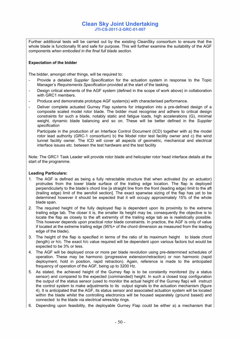
Clean Sky Joint Undertaking
JTI-CS-2011-2-GRC-01-007
- 50 -
Further additional tests will be carried out by the existing CleanSky consortium to ensure that the whole blade is functionally fit and safe for purpose. This will further examine the suitability of the AGF components when embodied in the final full blade section. Expectation of the bidder The bidder, amongst other things, will be required to: - Provide a detailed Supplier Specification for the actuation system in response to the Topic
Manager’s Requirements Specification provided at the start of the tasking. - Design critical elements of the AGF system (defined in the scope of work above) in collaboration
with GRC1 members. - Produce and demonstrate prototype AGF system(s) with characterised performance. - Deliver complete actuated Gurney Flap systems for integration into a pre-defined design of a
composite scaled model rotor blade. The bidder must recognise and adhere to critical design constraints for such a blade, notably static and fatigue loads, high accelerations (G), minimal weight, dynamic blade balancing and so on. These will be better defined in the Supplier specification
Participate in the production of an Interface Control Document (ICD) together with a) the model rotor lead authority (GRC-1 consortium) b) the Model rotor test facility owner and c) the wind tunnel facility owner. The ICD will cover all aspects of geometric, mechanical and electrical interface issues etc. between the test hardware and the test facility
Note: The GRC1 Task Leader will provide rotor blade and helicopter rotor head interface details at the start of the programme. Leading Particulars: 1. The AGF is defined as being a fully retractable structure that when activated (by an actuator)
protrudes from the lower blade surface of the trailing edge location. The flap is deployed perpendicularly to the blade’s chord line [a straight line from the front (leading edge) limit to the aft (trailing edge) limit of the aerofoil section]. The exact spanwise sizing of the flap has yet to be determined however it should be expected that it will occupy approximately 15% of the whole blade span.
2. The required height of the fully deployed flap is dependent upon its proximity to the extreme trailing edge tab. The closer it is, the smaller its height may be, consequently the objective is to locate the flap as closely to the aft extremity of the trailing edge tab as is realistically possible. This however depends upon practical rotor blade constraints. In practice, the AGF is only of value if located at the extreme trailing edge (95%+ of the chord dimension as measured from the leading edge of the blade).
3. The height of the flap is specified in terms of the ratio of its maximum height to blade chord (length) or h/c. The exact h/c value required will be dependent upon various factors but would be expected to be 3% or less.
4. The AGF will be deployed once or more per blade revolution using pre-determined schedules of operation. These may be harmonic (progressive extension/retraction) or non harmonic (rapid deployment, hold in position, rapid retraction). Again, reference is made to the anticipated frequency of operation of the AGF, being up to 3200 Hz.
5. As stated, the achieved height of the Gurney flap is to be constantly monitored (by a status sensor) and compared to the expected (commanded) height. In such a closed loop configuration the output of the status sensor (used to monitor the actual height of the Gurney flap) will instruct the control system to make adjustments to its output signals to the actuation mechanism (figure 4). It is anticipated that the AGF, its status sensor and associated actuation system will be located within the blade whilst the controlling electronics will be housed separately (ground based) and connected to the blade via electrical wires/slip rings.
6. Depending upon feasibility, the deployable Gurney Flap could be either a) a mechanism that

Clean Sky Joint Undertaking
JTI-CS-2011-2-GRC-01-007
- 51 -
deploys from within the blade section. Severe physical space constraints have to be considered. b) Devices that lie across or flat (flush) to the blade surface and increase in height (chordwise, spanwise or other orientation) c) other options of the invention of the bidder. The design of this mechanism is a key element of this package of work and must meet with the general needs of a model rotor blade’s design and operation as detailed in a Requirements Specification Document (issued at contract start). This document will be provided once the selected bidder has been contracted. The winning bidder would be expected to present design concepts of its intended mechanism(s) to the GRC1 consortium for preliminary approval ahead of full design/ test (Preliminary Design Review and Critical Design Review process).
7. The loads to be overcome by the actuation mechanism in deploying the AGF will depend upon deployment strategy. As an example theoretical case, for a Gurney flap of 0.11 M length, depth of 3% t/c ratio and located at 95% blade chord: Peak Gurney Flap Load (aerodynamic drag) is approx. 6.75 N, Peak Gurney Flap Root Moment approximately 0.0091Nm. (note - these numbers are indicative only, do not form any part of a formal specification and are subject to alteration)
8. A Requirements Specification (RS) covering the selection of materials, mechanical loading conditions and operating environment etc. will be supplied at the start of the programme. The use of non aerospace materials will need agreement.
9. Rotor blade mass and blade chordwise weight distributions are critical. Mass in total has to be strictly controlled (minimised) as the whirl test blade will have to comply with strict centrifugal force CF limits of the rotor hub
10. Rotor blades are usually chordwise balanced at around the 25% chord (measured from the aerofoil leading edge or ‘nose- figure 5). Mass added to the trailing edge of the blade should be kept to a minimum as it would need to be balanced with significant additional (parasitic) counter-mass, in the nose region. This creates a significant weight penalty and may also dynamically upset the blade.
11. For the key electrical components of the bidders elements of the AGF system (actuator and controlling electronics) it is strongly desired that the technology used is proven hardware/software and ideally a derivative of production or existing components/technology that need minimal change. Ideally the actuator and its controlling electronics will have been proven in combination. Proof will be sought.
12. Costs of operation of the wind tunnel are borne by the GRC 1 programme hence do not have to be considered by the bidders.
13. Monitoring of the behaviour and performance of the AGF system, and any necessary revisions of the AGF system during the wind tunnel tests will be required from the bidder.
14. Anticipated operating requirements of the model rotor system are as follows: Rotational speed : up to 1600 rpm Tip velocity of blade : 184 M/s G at blade tip ~2900 G at anticipated centre of Gurney Flap -1850 Frequency of operation : Once per blade revolution as a minimum, with possible 2 times per
blade revolution. 15. If possible the loads experienced by the Active Gurney flap mechanism should be recorded in
real time. This introduces a load cell (or other method/device) to be included between the actuator and the Gurney flap itself or some other suitable arrangement to be made.
16. The composite materials to be used in the construction of the blade have an upper working temperature limit of 70 0 C. This must be respected by the AGF system, and in particular the choice of any actuator.
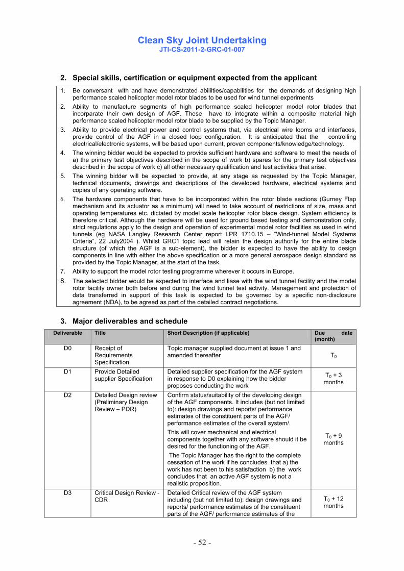
Clean Sky Joint Undertaking
JTI-CS-2011-2-GRC-01-007
- 52 -
2. Special skills, certification or equipment expected from the applicant 1. Be conversant with and have demonstrated abililties/capabilities for the demands of designing high
performance scaled helicopter model rotor blades to be used for wind tunnel experiments 2. Ability to manufacture segments of high performance scaled helicopter model rotor blades that
incorparate their own design of AGF. These have to integrate within a composite material high performance scaled helicopter model rotor blade to be supplied by the Topic Manager.
3. Ability to provide electrical power and control systems that, via electrical wire looms and interfaces, provide control of the AGF in a closed loop configuration. It is anticipated that the controlling electrical/electronic systems, will be based upon current, proven components/knowledge/technology.
4. The winning bidder would be expected to provide sufficient hardware and software to meet the needs of a) the primary test objectives described in the scope of work b) spares for the primary test objectives described in the scope of work c) all other necessary qualification and test activities that arise.
5. The winning bidder will be expected to provide, at any stage as requested by the Topic Manager, technical documents, drawings and descriptions of the developed hardware, electrical systems and copies of any operating software.
6. The hardware components that have to be incorporated within the rotor blade sections (Gurney Flap mechanism and its actuator as a minimum) will need to take account of restrictions of size, mass and operating temperatures etc. dictated by model scale helicopter rotor blade design. System efficiency is therefore critical. Although the hardware will be used for ground based testing and demonstration only, strict regulations apply to the design and operation of experimental model rotor facilities as used in wind tunnels (eg NASA Langley Research Center report LPR 1710.15 – “Wind-tunnel Model Systems Criteria”, 22 July2004 ). Whilst GRC1 topic lead will retain the design authority for the entire blade structure (of which the AGF is a sub-element), the bidder is expected to have the ability to design components in line with either the above specification or a more general aerospace design standard as provided by the Topic Manager, at the start of the task.
7. Ability to support the model rotor testing programme wherever it occurs in Europe. 8. The selected bidder would be expected to interface and liase with the wind tunnel facility and the model
rotor facility owner both before and during the wind tunnel test activity. Management and protection of data transferred in support of this task is expected to be governed by a specific non-disclosure agreement (NDA), to be agreed as part of the detailed contract negotiations.
3. Major deliverables and schedule Deliverable Title Short Description (if applicable) Due date
(month) D0 Receipt of
Requirements Specification
Topic manager supplied document at issue 1 and amended thereafter T0
D1 Provide Detailed supplier Specification
Detailed supplier specification for the AGF system in response to D0 explaining how the bidder proposes conducting the work
T0 + 3 months
D2 Detailed Design review (Preliminary Design Review – PDR)
Confirm status/suitability of the developing design of the AGF components. It includes (but not limited to): design drawings and reports/ performance estimates of the constituent parts of the AGF/ performance estimates of the overall system/. This will cover mechanical and electrical components together with any software should it be desired for the functioning of the AGF. The Topic Manager has the right to the complete cessation of the work if he concludes that a) the work has not been to his satisfaction b) the work concludes that an active AGF system is not a realistic proposition.
T0 + 9 months
D3 Critical Design Review - CDR
Detailed Critical review of the AGF system including (but not limited to): design drawings and reports/ performance estimates of the constituent parts of the AGF/ performance estimates of the
T0 + 12 months

Clean Sky Joint Undertaking
JTI-CS-2011-2-GRC-01-007
- 53 -
overall system/. This will cover mechanical and electrical components together with any software should it be desired for the functioning of the AGF.
D4 First Prototype system delivery
Provision of all relevant components to produce a single prototype AGF system to be incorporated within a model rotor blade (or representation).
T0 + 16 months
D5 Review and demonstration of: a) functional capability of the AGF system to operate within a representative environment (spin rig) b) suitability for integration into model rotor blades c) Demonstration /evidence/proof of the suitability of the AGF components for safe operation
Spin rig demonstration of the capabilities of the AGF system (G loads equivalent to model rotor blade). Spin rig to be provided by the bidder. Evidence from the spin rig tests and other tests to be used to confirm a) system functionality and b) suitability for incorporation into a functioning main rotor blade. Mechanical integration assessment of the AGF components within a model rotor blade representation (or actual blade). Supply report/test evidence /supporting documents, etc. to the GRC1 consortium and/or topic manager.
T0 + 17 months
D6 Supply of AGF systems including modification from lessons leant from D5
Supply of all relevant components to produce a refined AGF system(s) to be incorporated within a four bladed model rotor system (or representation). Supply also of two AGF spare blade sets AGF components to be subsequently modified to overcome any shortfalls in capability/non compliance to meet the needs of all tests
T0 + 20 months
D7 Support to test activities Monitoring and support during the Model rotor test activity (wind tunnel to be defined).
T0 + 27- 39 months
M8 Final report Detailed final report of tasks undertaken. T0 + 39 months
Note: The above table does not account for AGF system and component needs with respect to any evaluation or qualification testing, development activities etc. These also have to be provided by the bidder. Definition of terms: Chordwise Dimension through the aerofoil, starting from the blade leading edge (‘nose’) Spanwise Dimension along the length of the blade, usually measured from the blade’s centre of
rotation Leading edge Frontal most point/section of an aerofoil section Trailing edge Aft most point/section of an aerofoil section CF Centrifugal force AGF Active Gurney Flap GRS General Requirements Specification GRC Green Rotorcraft Consortium ART Active Rotor Technology AGF System Active Gurney Flap system - all mechanical. electrical and electronic systems to
produce a working AGF capability within a model rotor blade and operating on a model rotor test facility with closed loop control.

Clean Sky Joint Undertaking
JTI-CS-2011-2-GRC-01-007
- 54 -
4. Topic value (€) The total anticipated eligible cost of the proposal including manpower, travel costs, consumables, equipment, other direct costs, indirect costs, and subcontracting shall not exceed:
€ 300,000 (VAT not applicable) [Three hundred thousand euro]
5. Remarks - All core RTD activities have to be performed by the organisation(s) submitting the proposal. If some subcontracting is included in the proposal, it can only concern external support services for assistance with minor tasks that do not represent per se project tasks. The proposal must: - indicate the tasks to be subcontracted; - duly justify the recourse to each subcontract; - provide an estimation of the costs for each subcontract. (concerning subcontracting, see provisions of the Grant Agreement Annex II.7) - The expected length of the technical proposal is 25 pages.
Figure 1

Clean Sky Joint Undertaking
JTI-CS-2011-2-GRC-01-007
- 55 -
Figure 2 – Active Gurney flap responsibilities
Figure 3 – possible blade layout

Clean Sky Joint Undertaking
JTI-CS-2011-2-GRC-01-007
- 56 -
Figure 4
Figure 5 (note: section size exaggerated)

Clean Sky Joint Undertaking
JTI-CS-2011-2-GRC-03-009
- 57 -
Topic description
Topic Nr. Title
End Date December 2015 JTI-CS-2011-02 –GRC-03-009 Adaptation kit design & manufacturing: APU
Driving System Start Date T0
1. List of Acronyms AC: Alternating Current A/C: Aircraft APU: Auxiliary Power Unit CfP: Call for Proposal DC: Direct Current ETB: Electrical Test Bench EUT: Equipment Under Test G: Generator HMI: Human / Machine Interface HVDC: High Voltage Direct Current ITD: Integrated Technology Demonstrator. JTI: Joint Technology Initiative RTD: Research, Technology & Development S/G: Starter/Generator TBC: To Be Confirmed TBD: To Be Defined
2. Topic Description Background: In the frame of the Eco-Design ITD, verification activities will use an electrical test bench. This Electrical Test Bench (ETB) will support the electrical integration demonstration (generation, distribution, and electrical equipments) and the correlation of numerical models. In association with the aircraft (A/C) Equipments Under Test (EUT) the electrical test bench will have the capability to simulate electrical start of the aircraft engines & APU, as well as electrical generation. This topic addresses then the aircraft APU simulation function. Scope of work: The subject of this call for proposal addresses different aspects:
• Design • Manufacturing & integration • Acceptance on site & commissioning • Support, maintenance & repairs activities
of a complete driving system for a starter/generator electrical machine. This electrical machine will be a high-speed starter/generator, connected to the A/C APU (EUT). The objective is to provide the mechanical and control means to drive the starter/generator supplied by another member of CLEAN SKY. The driving system must be based on reversible driving electrical motors in order to simulate an aircraft APU engine from an electrical generation and starting system point of view.
Technical information: a) Technical characteristics of the EUT = Starter/Generator: Starter/Generator:
- Reversible machine (both operated in starter and generator) - Weight: 19 kg, overhung static moment = 25,2 Nm

Clean Sky Joint Undertaking
JTI-CS-2011-2-GRC-03-009
- 58 -
- Air cooled by forced air (53g/sec) - Bearing lubricated by oil (0.2 L/min) - Mechanical Interfaces to be communicated in further discussion. - Drive shaft line is horizontal (rationale = S/G local hydraulic circuit shall be oriented as per its
A/C installation)
Starting Mode: - Maximum mechanical torque: 7 N.m from 0 to 5500 rpm - Maximum mechanical power: 4 kW at 5500 rpm - Torque variation versus speed: linear between 7 N.m at 5500 rpm and 0 N.m at 28000 rpm - Start duration: 30s
Generating Mode: - Normal speed range: 48000 – 52000 rpm - Over speed: 56000 rpm - Output rectified DC voltage: 270 VDC - Permanent output power: 50 kW. - Over Load Capability: 85 kW (5 minutes)
100 kW (5seconds) b) Required Capability of the APU S/G Drive System The driving system must be oversized to be sure to meet over load / over speed / dynamic needs of the system (acceleration capability for instance). Light modifications of the S/G characteristics provided above may also occur during its design phase. As a design objective, the APU S/G drive shall be capable to reach 56,000 rpm in either direction. Operations in the 4 quadrants are required as well as moving from a quadrant to another while testing APU S/G Sequence. The torque over speed characteristic of the EUT is shown in the diagram below:
-8,53-9,95
-14,50
-16,91
-19,90
-8,53-9,95
0,00 0,00 0,000,00
7,007,007,00
-14,50
-16,91-17,05 -17,05
-19,90
-25,00
-20,00
-15,00
-10,00
-5,00
0,00
5,00
10,00
-80 000,00 -60 000,00 -40 000,00 -20 000,00 0,00 20 000,00 40 000,00 60 000,00 80 000,00
EUT starting modeEUT
generating mode
EUT generating
mode
Green curve: nominal operationOrange curve: over-load operation (5min)Red curve: over-load operation (5s)
Torque (Nm)
Speed (rpm)
EUT torque and speed characteristic c) Interfaces with the Electrical Test Bench (ETB) The general Interfaces between the ETB and equipment batches will be provided through a dedicated

Clean Sky Joint Undertaking
JTI-CS-2011-2-GRC-03-009
- 59 -
document to the partner at a later stage of the design activities. However, the following features relative to power and control system are interface constraints relative to the Electrical Test Bench for Cleansky. With regards to the implementation in the test facilities, the APU S/G Drive will be set in the test hall section. Electrical power (3 phases, 500V), pneumatic connection and cold water connection (TBC) is available in the test hall. From a control command point of view, the control system shall have a “local” and a “distant” remote control mode. In the local operating mode, the control and command orders can only be locally generated through the local Human / Machine Interface (HMI). When in “distant” mode, the APU S/G drive system is remotely controlled from the control room and the Human Machine Interface is reported in the control command room. Tasks are performed at different rates:
1- Some tasks are accomplished in a fast and deterministic manner: The local control system manages the safety aspects for the local bench (Safety relays are part of the CfP package as detailed in next paragraph). The local control system receives set points / curves and commands from the overall bench (when in this mode) The local system controls the torque or rotational speed with regards to the specified profile. Synchronise the local bench clock with the overall bench clock.
2- Tasks accomplished in non real time: Displays the local control panel, Upload locally recorded data at a fast sampling rate (up to 10kHz) to the overall test bench (voltages, currents, torque, speed, etc.)
Please note that the detailed interface will be finalized in a later stage and pieces of equipment specifications relative to the control system may be available and supplied to the CfP partner to satisfy the functions above. The local control system as shown below in the figure is in the scope of the CfP partner. The global control system of the ETB is not provided by the CfP partner but interfaces must be considered in order to allow a “distant remote control” mode.

Clean Sky Joint Undertaking
JTI-CS-2011-2-GRC-03-009
- 60 -
Subject of this CfP
Subject of this CfP
Scope of the CfP in the ETB environment

Clean Sky Joint Undertaking
JTI-CS-2011-2-GRC-03-009
- 61 -
d) The drive system supplied through this CfP will include:
- Mechanical driving system (including power electronics & control) - Torque measurement up to 1000 Hz minimum (initial calibration report included). - Shaft rotational speed measurement (initial calibration report included). - Mechanical coupling of the machines. - System supporting frame. Lifting ring or forklift interfaces are expected for any parts above 30
kg. - System internal cabling and associated protection. - Ancillaries if needed (lubrication system for the drive, etc.) - Covers for both drive and EUT. - The system must be robust to misalignment. - The drive control system shall be locally and remotely controllable from a separated control
room, protecting personnel from the high speed rotating machines. - The control system shall include speed and torque control mode; it shall allow to have torque
at 0 rpm. - The drive system will transfer data relative to the transducers measurements and also relative
to the health status of the system (OK, alarm on selected parameters, default) - Monitoring of the shaft line (through vibration measurement, temperature for instance) will be
included upon Applicant innovative suggestion - Safety features such as emergency shut down push-button and discrete data transfer to the
ETB is included in the topic. - Control system should display status; automatic actions should be done according to the level
of alarms (warning: warn the bench operator who has to take a decision / emergency: automatic shut down procedure to protect people & the installation).
- Safety circuit different from command circuit. - Maintenance in operating state for the whole system during the project, including spare parts,
repairs activities and support. - Validation of the System when it is coupled with the S/G APU (EUT) - The transition between the Starting mode and the Generating mode must be done without fits
and starts. - Documents:
o Detailed documentation (detailed description, operations, protocols) o Safety analysis o Electrical and mechanical interfaces drawings o Maintenance procedures
As an option, a lubrication / cooling unit for the APU S/G with characteristics to be defined shall be provided by the partner.
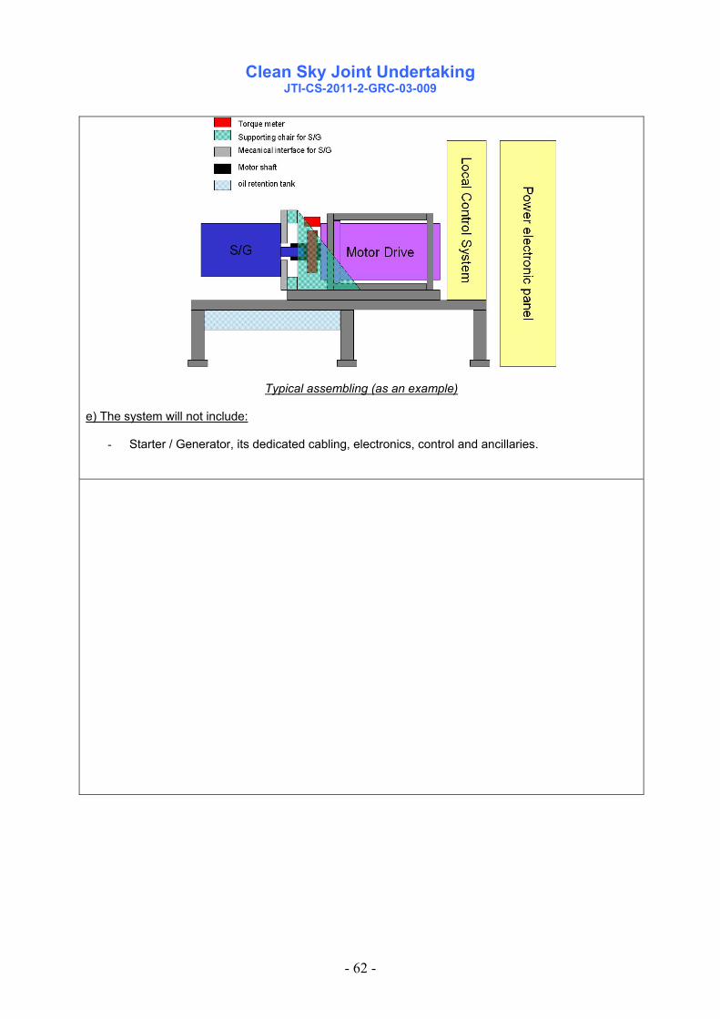
Clean Sky Joint Undertaking
JTI-CS-2011-2-GRC-03-009
- 62 -
Typical assembling (as an example) e) The system will not include:
- Starter / Generator, its dedicated cabling, electronics, control and ancillaries.

Clean Sky Joint Undertaking
JTI-CS-2011-2-GRC-03-009
- 63 -
3. Special Skills, certification or equipment expected from the applicant The proposal should include:
Detailed study of the solution. Manufacturing / integration of the system. Integration and intermediate acceptance testing on CfP Supplier site. Commissioning on ETB site of the system as well as support until final acceptance. Support, maintenance and repairs activities for the project duration.
The system should be innovative, either by the solution, or by technology, materials, control loop design or monitoring. As leads, you may explore fields like:
Torque transducers to minimize the shaft’s length (torque flange sensors, etc.) If used, the reducers/multipliers gears’ design could have a very high efficiency by using an
innovative technology (superlubricity, oil-less, etc.). If no reducers/multipliers are used, very high speed (up to 56 000 rpm or even more) direct drive
system solutions could be explored. Mass optimized
Obviously, the innovative technology possibilities are not reduced to the leads describe above and the applicants are free to propose their solutions to obtain an innovative drive system for the ETB regarding existing test rigs in aerospace industry. Criteria to meet: The system will be as compact, robust and optimised as possible: the bench (supporting frame, drive, instrumentation, lubrication system, power electronics, etc.) should be contained in a specific allocated space: 3m x 3m x 2.50m (l x L x h ) as a maximum; the 9m² is a total working allocated surface that shall include personnel access to perform the required operations on the equipment or its ancillaries. Those operations are, but may not be limited to:
- Assembly,
- Rigging;
- Maintenance operations.
Operations on a dedicated area/equipment shall not impact another equipment-dedicated area..
The compactness of the proposed solutions will be a selection criteria for the CfP.
Space allocated for the APU drive test bench
• The system will use as few lubrication systems and servitudes as possible. • The system will require reduced maintenance time, have a low cost of operation and a high level of
safety and robustness. The scope of the CfP is design, manufacture, integration and validation of the system.

Clean Sky Joint Undertaking
JTI-CS-2011-2-GRC-03-009
- 64 -
4. Major deliverables and schedule
Deliverable Title Description (if applicable) Due date
D1 PDR Preliminary Design Review T0 + 3 month
D2 CDR Critical Design Review T0 + 6 month
D3 Manufacturing and delivery Delivery of the complete systems T0 + 12 month
D4 Commissioning and acceptance Acceptance of the complete systems T0 + 14 month
D5 Support, maintenance & repairs
Further to the commissioning on site, the CfP Supplier shall support the rig operations to correct potential faults during the Clean Sky Program.
December 2015
Detailed list of deliverables and milestones will be defined with the CfP partner in the Description of Work.
5. Topic value (€) The total value of biddings for this work package shall not exceed
€ 430.000,-- [Four hundred thirty thousand euro]
Please note that VAT is not applicable in the frame of the Clean Sky program.
6. Remarks - All core RTD activities have to be performed by the organisation(s) submitting the proposal. If some subcontracting is included in the proposal, it can only concern external support services for assistance with minor tasks that do not represent per se project tasks. The proposal must : - Indicate the tasks to be subcontracted; - Duly justify the recourse to each subcontract; - Provide an estimation of the costs for each subcontract. (concerning subcontracting, see provisions of the Grant Agreement Annex II.7)

Clean Sky Joint Undertaking
JTI-CS-2011-2-GRC-03-009
- 65 -
APU Drive System principle / Scope of the CfP
Control Box

Clean Sky Joint Undertaking
Call SP1-JTI-CS-2011-02 Sustainable and Green Engines
- 66 -
Clean Sky – Sustainable and Green Engines
Identification topics VALUE MAX FUNDJTI-CS-SAGE 3 4.300.000 3.225.000JTI-CS-SAGE-01 JTI-CS-SAGE-02 JTI-CS-SAGE-03 1.800.000
JTI-CS-2011-2-SAGE-03-012 1.800.000JTI-CS-SAGE-04 2.500.000
JTI-CS-2011-2-SAGE-04-015 1.500.000JTI-CS-2011-2-SAGE-04-016 1.000.000
JTI-CS-SAGE-05
Area-03 - Large 3-shaft turbofan
Development of Innovative SLM-Machinery for High Temperature Aero Engine ApplicationsLow Pressure Turbine Surface Temperature Measurement for Geared Turbo Fan Turbine Application
Non-metallic Pipes for Aeroengine DressingsArea-04 - Geared Turbofan
Area-05 - Turboshaft
Clean Sky - Sustainable and Green EnginesITD - AREA - TOPIC
Area-02 - Direct Drive Open RotorArea-01 - Geared Open Rotor

Clean Sky Joint Undertaking
JTI-CS-2011-2-SAGE-03-012
- 67 -
Topic Description
CfP topic number Title
Start date Jan 2012 JTI-CS-2011-2-SAGE-03-012 Non-metallic Pipes for Aeroengine Dressings End date Dec 2013
1. Topic Description
SAGE3 project aims at development and demonstration of a large 3-shaft bypass engine Demonstrator. RTD activities are foreseen on developing non-metallic pipes and support system, to replace traditional metallic variants in engine externals. The objective of the work package is to develop this technology and demonstrate to Technology Readiness Level (TRL)6. The operating temperature range capability of interest is -85°C to at least 165°C, but technologies capable of higher temperatures would be strongly preferred. The new non-metallic material must be Fire resistant to JES314-1 (which conforms to ISO2685) as a minimum and the system capable of continued operation in an engine environment. The Partner shall in particular perform the following tasks: Task 1 Design and analysis of non-metallic pipework/supports The Partner will conduct the mechanical concept and detail design of both pipework in a non-metallic material and of a suitable support system against supplied specification requirements (see below). The Partner should also consider the use of traditional metallic end fittings. Whilst initial investigations into this technology have utilised current metallic fittings, the Partner is expected to recommend alternatives. The use of traditional P-clips and brackets adds weight and cost to an installation and so proposals for novel and integrated mounting systems optimised to the support of the non-metallic pipes are encouraged. The Partner will provide a detailed verification proposal for the new material/manufacturing process. The piping solution should be demonstrated to TRL6 (i.e. in a representative engine environment) and proposals should include a technology validation plan to show how this requirement will be met. If it is expected that the SAGE Members will contribute to the delivery of this plan then this should be highlighted. Any material testing or manufacturing trials required to validate the design choices shall be carried out and reported by the Partner to the Topic Manager. Task 2: Non-metallic pipework/supports manufacturing and assembly The Partner will procure all materials and fittings and manufacture all material coupons, test parts and components for rig testing necessary to support validation of the pipe and support design and manufacturing technology. Pipes and supports will be required for practical integration and assembly demonstration on an engine. If it is agreed between the Partner and Topic Manager that a running engine test is required as part of the technology validation plan then the Partner will also be required to provide a number of parts for

Clean Sky Joint Undertaking
JTI-CS-2011-2-SAGE-03-012
- 68 -
this testing. Proposals should indicate whether this is envisaged, the number of pipes likely to be required and the features requiring this validation. Task 3: Non-metallic pipework/supports validation support If it is agreed that engine testing is required then, the Partner shall support engine testing through the preparation, test and appraisal phases. During any engine build it is envisaged that some on-site support will be required. The Partner will supply all instrumentation necessary to validate the pipes and supports and components will be supplied already instrumented whenever possible. Non-metallic pipes and supports operating environment
Min MaxTemperature capability -85°C >165°CPipe outside diameter 0.25" 1.5"Pipe bend radii 1.5 x ODPipe length 1.8mPressure capability -10psig 450psig working, 800psig max New non-metallic material must be Fire resistant to JES314-1 (which conforms to ISO2685), as a
minimum Typical vibration 3 axes requirements: 0.030’’ pk-pk 10-37Hz 3.5’’/sec pk 37-263Hz 15g pk 263-2000Hz Systems capability: Air and Oil – drains, scavenge, sensor and vent lines Demonstrated spill resistance to Skydrol hydraulic fluid and aviation fuel
2. Special skills, certification or equipment expected from the applicant Extensive experience in the detail design, development and manufacture and validation of non-metallic materials. In-service operation of aerospace pipework would be an advantage. Experience of suitable quality control systems is essential. Successful experience, with demonstrable benefits, of application of innovative manufacturing and material technologies to reduce weight and cost of parts is an asset. Availability of technologies at an high technology readiness level to minimise programme risks is an asset. Experience in R&T and R&D programs. Experience of aerospace applications would be an advantage. The Partner needs to be in the position to have access to the manufacturing facilities suitable for making an agreed subset of non-metallic pipes suitable for engine test if required. The Partner needs to have access to rig test facilities for vibration & thermal endurance testing. The activity will be managed with a Phase & Gate approach and management plan has to be provided. The Topic Manager will approve gates and authorise progress to subsequent phases. Technical/program documentation, including planning, drawings, manufacturing and inspection reports, must be made available to the Topic Manager.
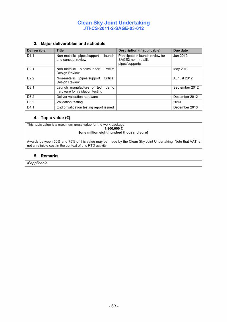
Clean Sky Joint Undertaking
JTI-CS-2011-2-SAGE-03-012
- 69 -
3. Major deliverables and schedule Deliverable Title Description (if applicable) Due date D1.1 Non-metallic pipes/support launch
and concept review Participate in launch review for SAGE3 non-metallic pipes/supports
Jan 2012
D2.1 Non-metallic pipes/support Prelim Design Review
May 2012
D2.2 Non-metallic pipes/support Critical Design Review
August 2012
D3.1 Launch manufacture of tech demo hardware for validation testing
September 2012
D3.2 Deliver validation hardware December 2012 D3.2 Validation testing 2013 D4.1 End of validation testing report issued December 2013
4. Topic value (€) This topic value is a maximum gross value for the work package.
1,800,000 € [one million eight hundred thousand euro]
Awards between 50% and 75% of this value may be made by the Clean Sky Joint Undertaking. Note that VAT is not an eligible cost in the context of this RTD activity.
5. Remarks If applicable

Clean Sky Joint Undertaking
JTI-CS-2011-2-SAGE-04-015
- 70 -
Topic Description
CfP topic number Title
Start date T0 JTI-CS-2011-02-SAGE-04-015 Development of Innovative SLM-Machinery for High Temperature Aero Engine Applications
End date T0+36M
1. Topic Description
A first generation of geared turbofan engine (GTF) technology has found its way into the regional and narrow body market due to significant reductions in fuel consumption and noise compared to conventional turbo fan engines. The purpose of the advanced GTF demonstrator as part of the Sustainable and Green Engine (SAGE) platform is to further advance these technologies and to achieve a next step change in fuel burn reduction combined with an additional decrease in noise emission. Components and modules with new technologies are to be developed, implemented and validated through rig testing as required before integration into a donor engine and SAGE4 full engine demonstration. The successful validation of technologies for this aircraft engine concept will then facilitate the early introduction of innovative new products into the market, and significantly reduce the environmental impact of air transport. In order to answer the needs of the SAGE4 geared turbofan in terms of research, technological development and demonstration activities, it is planned to offer individual tasks to the industry, universities or any legal entity. Therefore, the present Call for Proposal supports the further development of manufacturing methods with a high optimization potential to allow alternate designs of environment-friendly aero-engine components, fabricated by means of an additive manufacturing process. The overall aim of this present Call for Proposal is to utilize the existing knowledge and know how of the state-of-the-art powder bed SLM process and to develop the ability of the potential CLEAN SKY partner to manufacture aero engine parts in a larger size as it is possible today and in a quality that is adequate to incorporate the units into the SAGE4 GTF Demonstrator Engine. The objective of this Call is limited to two Nickel based alloys The quality of the parts is mature enough to launch a short term serial production (TRL-6). MERLIN, another substantial FP7 project addresses complementarily to this CfP topic research activities at TRL3-4 to develop and evaluate various methods of the Additive Manufacturing Process applying a broad variety of materials. The more fundamental approach of MERLIN should provides important information that could be used to further improve the powder bed SLM process at a later stage. Selective Laser Melting (SLM) or Direct Metal Laser Sintering (DMLS) are additive manufacturing processes of joining powder materials layer by layer to build objects from 3D model data. These processes offer the possibility to change a manufacturing driven design to a design driven manufacturing and therefore building bionically shaped parts optimized in weight and function. These very attractive processes for aerospace applications require the machinery to be adapted for the demands of aero engine parts. These parts are mostly made of high heat resistant superalloys which often can not be machined by several processes. This is the case with some special casting materials, that can not be laser-welded with the unmodified systems of current SLM/DMLS machines. Therefore, the highly innovative, main task for the partners is to develop a SLM/DMLS machine capable to machine high sophisticated aero engine superalloys and at the same time it is suitable for series production.

Clean Sky Joint Undertaking
JTI-CS-2011-2-SAGE-04-015
- 71 -
The SLM/DMLS machines to be developed have to be capable of the following: Requirement 1: Capability of building MAR M247 with adequate material quality Some high temperature resistant materials used in aero engines are not weldable with current technics. The steep temperature gradients between melting pool and surrounding area during the welding process lead to unacceptable cracks in the material. Because SLM/DMLS is a laser welding process, materials like the γ’ strengthened superalloy MAR M247 can not be build crack-free with current machines. Therefore the top priority requirement is to develop a prototype SLM-Machine capable of setting process parameter, that ensure crack-free and dense (porosity < 1%) building of Mar M247 parts. The machine has to provide process conditions, that lead to a sufficiently flat temperature gradient between melting pool and surrounding area. Solutions could be e.g. additional heating systems of any kind to control the heat flux from the melting area in an appropriate way. The development work will be an iterative process, where the partner provides specimens produced by a SLM/DMLS machine at a particular development stage to Topic Manager, then Topic manager tests and analyses these specimens and afterwards the appropriate parameters (temperature range, cooling time etc.) of the machine are discussed and defined by both partys to improve the specimen properties. Requirement 2: Capability of cost effective serial production Concerning serial production machines, the occupational health and safety standard of an industrial machine has the highest priority. Especially when handling with hazardous powder of superalloys, it is required the development of systems that ensure operational safety for the operator. In order to produce aero engine casings, the machine has to own a building volume of 350 x 250 x 250 mm. To assure an economical serial production, an appropriate degree of automation of the process chain (e.g. powder supply/recycling, part cleaning/removal) and build up rate are required. To prove output information suited for quality management of aerospace parts, and guarantee stability and reproducibility, it is essential that an adequate online process monitoring system is implemented or can additionaly be implemented by Topic Manager. Based on the given requirements, the partners work includes the following tasks: Task 1: Management Organisation: – The partner shall nominate a team dedicated to the project and should inform Topic Manager about the name/names of this key staff. At least the responsibility of the following functions shall be clearly addressed: Program (single point contact with Topic Manager), Technics & Quality. Time Schedule & Workpackage Description: – The partner is working to the agreed time-schedule & workpackage description. – Both, the time-schedule and the workpackage description layed out in this Call shall be further detailed as required and agreed at the beginning of the project. Progress Reporting, Reviews & Risk Assesment: – Quarterly progress reports in writing shall be provided by the partner, referring to all agreed workpackages, technical achievement, time schedule, potential risks and proposal for risk mitigation. – Regular coordination meetings shall be installed (preferred as telecon). – The partner shall support reporting and agreed review meetings with reasonable visibility on its activities and an adequate level of information. – The review meetings shall be helt in Topic Manager facility.

Clean Sky Joint Undertaking
JTI-CS-2011-2-SAGE-04-015
- 72 -
General Requirements: – The partner shall work to a certified standard process. Task 2: Analysis – The partner shall study and evaluate the given requirements for the SLM/DMLS-machine, benchmark the technical choices and select the adequate technology in order to fulfill the given requirements. – The partner shall demonstrate in a first phase which is the better and most suitable approach, giving a solid guideline, to develop the SLM/DMLS maschine with the given requirements. Task 3: Development & Validation In order to develop a SLM/DMLS machine capable to machine high sophisticated aero engine superalloys and assure its suitability for serial production, the partner must have a close interaction with Topic Manager. – The partner shall improve machine components to provide optimized parameter settings. – The partner has to deliver specimens at least one month before each regular review meeting (at least every half year) to ensure enough testing time. – Topic Manger will do the testing and analysis of these specimens. – According to the extensive know-how concerning Mar-M247, Topic Manager will define the needed process parameters. – In the regular review meetings Topic Manager and its partner will then determine further approaches to adapt machine components. – In conformity to this iterative optimizing procedure the partner shall construct a prototype of a SLM/MLS maschine which fulfills the mentioned requirements.
2. Special skills, certification or equipment expected from the applicant The applicant has to be a producer of SLM/DMLS-machines, who will develop the above mentioned techniques and implement them in commercial available machines. Thus the applicant should have: – At least several years experience in the development and production of SLM/DMLS systems – Experience in the aerospace market, ideally with SLM/DMLS systems already producing aero engine components for some years at companies within the aerospace industry – ISO 9001 certification covering the development, production and service of SLM/DMLS systems – Sufficient R&D resources and competence to enable the development of the deliverables, including mechanics, optics, software, materials and process development – Capability to ensure reliable availability of production machinery following success of the development project, including sales and service organization in all relevant regions worldwide, adequate financial resources, and necessary IP rights – Ideally existing experience in at least some of the project topics, e.g. SLM/DMLS of non-weldable superalloys, integrated process and quality control systems, etc. – Ideally experience in collaborative R&D projects in the field of SLM/DMLS

Clean Sky Joint Undertaking
JTI-CS-2011-2-SAGE-04-015
- 73 -
3. Major deliverables and schedule Deliverable Title Description (if applicable) Due date D1 Technical specification sheet schedule with starting approaches (machine
concepts), detailed technical deliverables checked in reviews & milestones
T0
D2 Iterative concept selection/adaption on laboratory scale set-up
Iteration process where the partner provides specimens to MTU 1 month before review (at least 2 reviews per year). MTU tests specimens in that time and gives feedback within the review.
T0 + min. every 6M until 24M
D3 Final prototype concept Iterative development and adaption of machine concepts completed; processability of final concept proven on laboratory set-up
T0 + 24M
D4 Prototype machine Construction of prototype machine (with progress review held at D0 + 29M) completed
T0 + 34M
D5 Validation of prototype by manu-facturing demonstrator parts
Prototype validation is closed and SLM/DMLS machine fulfills requirements; demonstrator parts built
T0 + 36M
4. Topic value (€) This topic value is a maximum gross value for the work package
1,500,000 € [one million five hundred thousand euro ]
. Awards between 50% and 75% of this value may be made by the Clean Sky Joint Undertaking.
5. Remarks

Clean Sky Joint Undertaking
JTI-CS-2011-2-SAGE-04-016
- 74 -
Topic Description
CfP topic number Title
Start date Dec. 2011 JTI-CS-2011-02-SAGE-04-016 Low Pressure Turbine Surface Temperature Measurement for Geared Turbo Fan Turbine Application
End date Aug. 2013 (21 month)
1. Topic Description
A first generation of geared turbofan engine (GTF) technology has found its way into the regional and narrow body market due to significant reductions in fuel consumption and noise compared to conventional turbo fan engines. The purpose of the advanced GTF demonstrator as part of the Sustainable and Green Engine (SAGE) platform is to further advance these technologies and to achieve a next step change in fuel burn reduction combined with an additional decrease in noise emission. Components and modules with new technologies are to be developed, implemented and validated through rig testing as required before integration into a donor engine and SAGE4 full engine demonstration. The successful validation of technologies for this aircraft engine concept will then facilitate the early introduction of innovative new products into the market, and significantly reduce the environmental impact of air transport. In order to answer the needs of the SAGE4 geared turbofan in terms of research, technological development and demonstration activities, it is planned to offer individual tasks to the industry, universities or any legal entity. Therefore, the present Call for Proposal project is intended to develop and demonstrate technologies that will provide the capability to measure temperature in the turbine of a geared turbo fan engine while in development testing. The design of new gas turbine engines, including the geared turbofan, is driving higher turbine temperatures which cause designers to apply more advanced materials, thermal protection systems and cooling treatments. In order to predict component life, it is necessary to more fully understand the actual operating environment that the turbine parts are being subjected to. As such an improved measurement system capable of operating in the turbine during an engine test is needed. It is necessary to better understand the relative and local surface temperatures of turbine components, as well as the coating system performance and the cooling system performance while in operation. A measurement system is needed to perform high-resolution, real-time; full-surface scans of rotating turbine blades and static components. Current technology, such as thermocouples are limited to point measurements; therefore an inordinate quantity of gauges would be required to fully characterize the operating environment for the turbine parts. To gather data with high spatial resolution especially near cooling holes or at regions with significant temperature gradients a comprehensive method is required. Available technologies and recent developments concentrate on the use of infrared pyrometers. Unfortunately this technology offers the limited field of view of a line scan of the rotating part only. Additionally, the line scan may be restricted based on the geometry of the components. The main focus was on stationary power gas turbines and with long time durability for engine health monitoring and blade to blade comparisons. Requirements of short term, very accurate measurements in aero engine development tests have not been addressed. The spot sensors available – even when several spots are used in parallel or do scanning at rotating parts – do not have a sufficient spatial resolution to monitor the phenomena mentioned above in real aero gas turbines. The measurement accuracy with state of the art infrared technology to map temperatures is limited due to large local variations in surface properties and reflections of the radiation originated by other hot parts. These and other techniques or optical methods can potentially be developed to provide comprehensive measurement of turbine parts. There are challenges interfacing current optical imaging systems with an operational gas turbine engine. In addition, measuring surface temperatures on parts with ceramic thermal barrier coatings offer further challenges and therefore drives the need for a new step in measurement system technology development activity. The task can not be limited to the

Clean Sky Joint Undertaking
JTI-CS-2011-2-SAGE-04-016
- 75 -
integration of a known infrared imaging system into the turbine. A detailed study on the behaviour of typical turbine materials and their surface emission and reflection properties is required as well as an evaluation of reflections from the geometrical environment to get a significant improvement of the accuracy. The environmental conditions that are typically found in the turbine will obviously present significant challenges for a new measurement system. First and foremost, the high temperatures and vibratory stresses that exist, can damage probe housings and components in an optical solution. Contaminants in the airflow can seriously reduce the system’s ability to look through the main gas-path to the surface of the rotating parts. The objective of this program is to develop and demonstrate a remote sensing system which has the response time and resolution that is capable of operating at advanced engine conditions with minimal impact on engine performance and operation. The system should not have any directly mounted sensors on the components of interest. One specific application involves monitoring of low pressure turbine blades and static components in the turbine. The sensing device will be integrated into an operating engine up to full power and should allow for applicable field of views and orientations. For example, the sensing device should allow for viewing of various spans of desired parts. In addition, the sensing device installation should allow for it to be rotated such that multiple stages within the engine can be monitored. This would include multiple blade rows as well as viewing the last blade row and turbine exhaust case. Specific requirements: The system developed shall fulfil the requirements specified. Installation: • The probe will be installed in the casing of the low pressure turbine (but not limited to that) to
monitor the lower half of rotating turbine blades and not rotating vanes. A provision to do measurements at the outer shroud should be suggested but not necessarily integrated in the design.
• Suitable for vibratory stresses and contaminants in the airflow typical for aero gas turbines • maintenance free operation for a minimum of 8 hours • Boroscope like probe with outer diameter of 10 to 15 mm maximum • Gas temperatures up to 1200°C, wall temperature around probe up to 950°C • Distance from probe tip to measured surface 20 to 200 mm • A surface treatment to optimize the spectral behaviour of the surface can be suggested but must
not change the thermal and aerodynamic properties of the parts. Measurement: • Range from 400° to 1200°C surface temperature • Accuracy within 2% of measured value, local differences in temperature within 1% of the average
measured value • Spatial resolution 1% of measurement distance (around 1 mm) on stationary and rotating parts for
rotational speeds up to 12.000 rpm. • Data capture rate of 10 complete surface measurements per second, a minimum of 2 could be
accepted Analysis: The system shall deliver a calibrated temperature distribution within the accuracy specified with respect to • local and temporal changes of surface emissivity and viewing angle • reflections from surrounding parts • radiation of gas and particles in the gas flow Task 1: Management
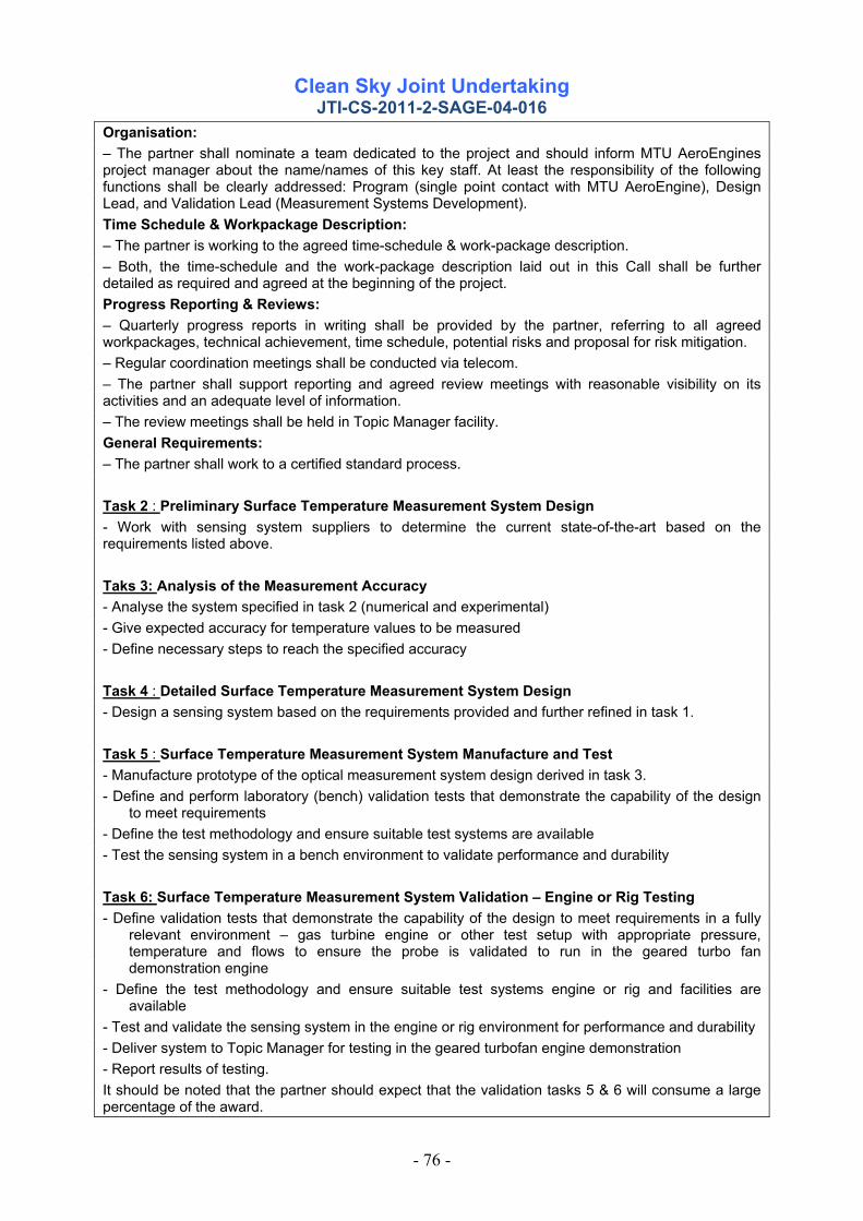
Clean Sky Joint Undertaking
JTI-CS-2011-2-SAGE-04-016
- 76 -
Organisation: – The partner shall nominate a team dedicated to the project and should inform MTU AeroEngines project manager about the name/names of this key staff. At least the responsibility of the following functions shall be clearly addressed: Program (single point contact with MTU AeroEngine), Design Lead, and Validation Lead (Measurement Systems Development). Time Schedule & Workpackage Description: – The partner is working to the agreed time-schedule & work-package description. – Both, the time-schedule and the work-package description laid out in this Call shall be further detailed as required and agreed at the beginning of the project. Progress Reporting & Reviews: – Quarterly progress reports in writing shall be provided by the partner, referring to all agreed workpackages, technical achievement, time schedule, potential risks and proposal for risk mitigation. – Regular coordination meetings shall be conducted via telecom. – The partner shall support reporting and agreed review meetings with reasonable visibility on its activities and an adequate level of information. – The review meetings shall be held in Topic Manager facility. General Requirements: – The partner shall work to a certified standard process. Task 2 : Preliminary Surface Temperature Measurement System Design - Work with sensing system suppliers to determine the current state-of-the-art based on the requirements listed above. Taks 3: Analysis of the Measurement Accuracy - Analyse the system specified in task 2 (numerical and experimental) - Give expected accuracy for temperature values to be measured - Define necessary steps to reach the specified accuracy Task 4 : Detailed Surface Temperature Measurement System Design - Design a sensing system based on the requirements provided and further refined in task 1. Task 5 : Surface Temperature Measurement System Manufacture and Test - Manufacture prototype of the optical measurement system design derived in task 3. - Define and perform laboratory (bench) validation tests that demonstrate the capability of the design
to meet requirements - Define the test methodology and ensure suitable test systems are available - Test the sensing system in a bench environment to validate performance and durability Task 6: Surface Temperature Measurement System Validation – Engine or Rig Testing - Define validation tests that demonstrate the capability of the design to meet requirements in a fully
relevant environment – gas turbine engine or other test setup with appropriate pressure, temperature and flows to ensure the probe is validated to run in the geared turbo fan demonstration engine
- Define the test methodology and ensure suitable test systems engine or rig and facilities are available
- Test and validate the sensing system in the engine or rig environment for performance and durability - Deliver system to Topic Manager for testing in the geared turbofan engine demonstration - Report results of testing. It should be noted that the partner should expect that the validation tasks 5 & 6 will consume a large percentage of the award.

Clean Sky Joint Undertaking
JTI-CS-2011-2-SAGE-04-016
- 77 -
2. Special skills, certification or equipment expected from the applicant
-The partner must have experience in the design, fabrication, and testing of aerospace measurement systems. - The partner must have access to appropriate testing facilities and deliver a plan indicating how they will meet this requirement.
3. Major deliverables and schedule Deliverable Title Description (if applicable) Due date
D1 Detailed project plan Schedule with milestones T0+1M D2 Preliminary Surface
Temperature Measurement System Design Report
Present one or more potential measurement system concepts for review and approval
T0+4M
D3 Measurement Accuracy Analysis Report
Report expected measurement accuracy for typical applications with the best available concept.
T0+12M
D4 Detailed Surface Temperature Measurement System Design Report
Report to contain detailed drawings, predicted capability, and results of any analysis performed during the design process.
T0+12M
D5 Manufacture Prototype Release Report
Results of bench testing and verification that the prototype system will meet engine test requirements
T0+15M
D6 Engine or Rig Test Report Results of fully relevant rig or gas turbine engine test and verification that the prototype system will meet engine test requirements
T0+18M
D7 Surface Temperature Measurement System Test Report
A report providing an overview of: -Sensing system performance - Recommendations to support TRL progression -Recommended changes for next iteration
T0+21M
4. Topic value (€) This topic value is a maximum gross value for the work package
1,000,000 € [one million euro ]
. Awards between 50% and 75% of this value may be made by the Clean Sky Joint Undertaking.
5. Remarks Measurement companies who reply to this call for proposal are encouraged to partner with research institutes or universities for analysis and system evaluation tests. If a partnering arrangement is not feasible the applicant has to show sufficient knowledge and equipment to prove the accuracy of the system developed.
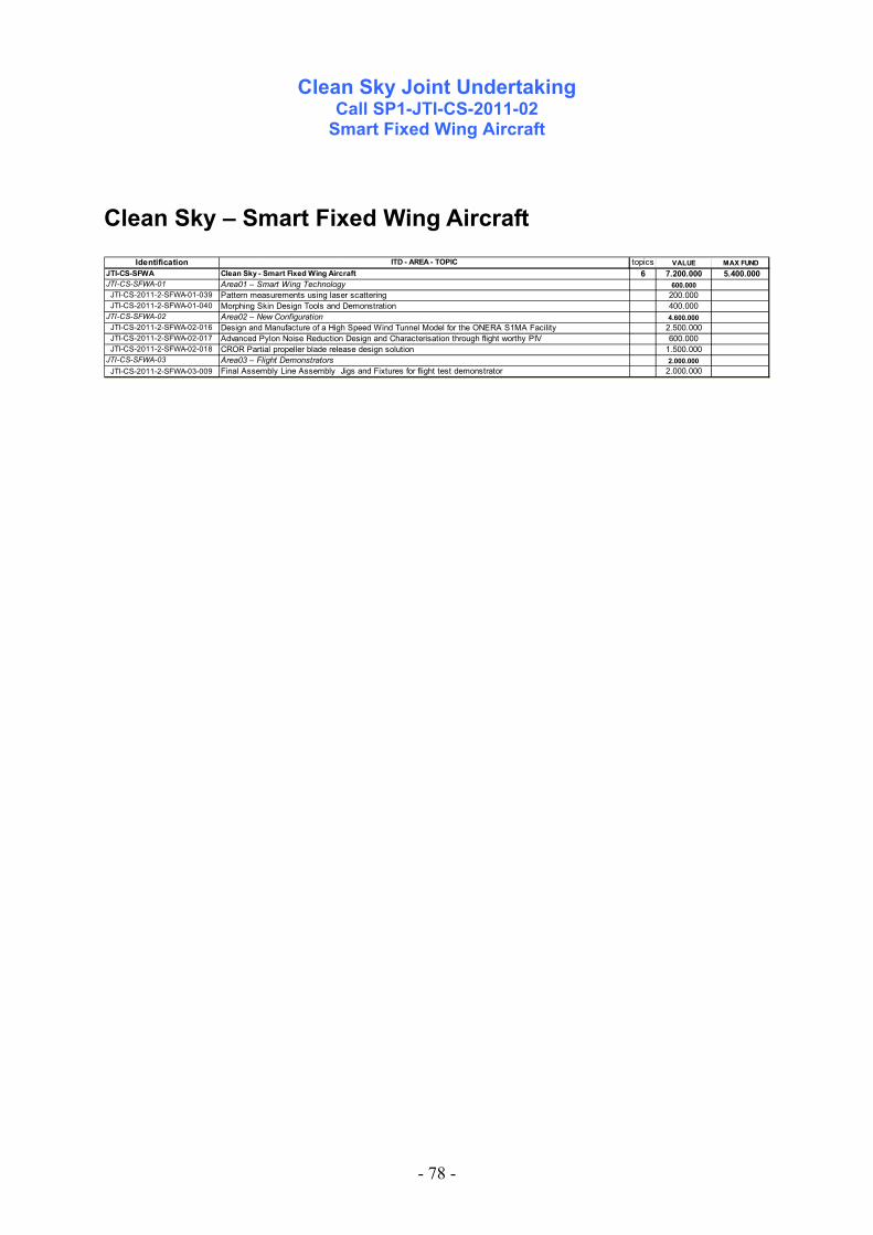
Clean Sky Joint Undertaking
Call SP1-JTI-CS-2011-02 Smart Fixed Wing Aircraft
- 78 -
Clean Sky – Smart Fixed Wing Aircraft
Identification topics VALUE MAX FUNDJTI-CS-SFWA 6 7.200.000 5.400.000JTI-CS-SFWA-01 600.000
JTI-CS-2011-2-SFWA-01-039 200.000JTI-CS-2011-2-SFWA-01-040 400.000
JTI-CS-SFWA-02 4.600.000JTI-CS-2011-2-SFWA-02-016 2.500.000JTI-CS-2011-2-SFWA-02-017 600.000JTI-CS-2011-2-SFWA-02-018 1.500.000
JTI-CS-SFWA-03 2.000.000JTI-CS-2011-2-SFWA-03-009 2.000.000
ITD - AREA - TOPIC
Advanced Pylon Noise Reduction Design and Characterisation through flight worthy PIV
Pattern measurements using laser scattering
CROR Partial propeller blade release design solutionArea03 – Flight DemonstratorsFinal Assembly Line Assembly Jigs and Fixtures for flight test demonstrator
Design and Manufacture of a High Speed Wind Tunnel Model for the ONERA S1MA Facility
Morphing Skin Design Tools and DemonstrationArea02 – New Configuration
Clean Sky - Smart Fixed Wing AircraftArea01 – Smart Wing Technology

Clean Sky Joint Undertaking
JTI-CS-2011-02-SFWA-01-039
- 79 -
Topic Description Topic Number Title
Start Date 01/11/11 JTI-CS-2011-02-SFWA-01-039 Pattern measurements using laser scattering End Date 01/05/13
1. Description Micro structured surface coatings (e.g. Riblets), if applied to aircraft wing and/or body components have the potential of reducing the fuel consumption by up to 3 %. However, the efficiency of the drag reduction is very sensitive to the triangular geometry of Riblets. Small degradations (below 10 microns) of the geometry, particular to the sharp edges of the Riblets, caused by erosion or surface contamination, lead to a drastic decrease of achievable drag reduction. Therefore the Riblet geometry has to be monitored in course of aircraft maintenance.
For this purpose a concept of an optical sensor is studied within the Clean Sky project which is based on the measurement of scattering pattern induced by grazing incidence of laser beams. To verify this concept the correlation between surface geometry and scattering patterns hall be investigated in this CfP topic. For a fundamental study of the scattering pattern the optical properties of the coating system shall be studied by ultra fast Laser spectroscopy in the UV/VIS/MIR range and by holographic methods. In addition, a suitable laser system has experimentally to be selected and optimized by the applicant for obtaining the ideal scattering patterns. In order to determine and optimize different laser systems, a preliminary configuration for detecting scattering patterns has to be set up.
The work has to be performed in the lab of the applicant. The applicant has to set up a preliminary configuration for the detection of scattering patterns.
The tested Riblet material is going to be delivered by Clean Sky partners, particularly IFAM.
2. Special Skills, certification or equipment expected from the applicant • Experience in calculation of scattering patterns of three-dimensional structures (software based) calculation
is recommended • High experience in holographic methods • Broad knowledge of optics, laser systems • Ability to specify, optimize or develop laser systems • Ability to determine optical constants of coating materials
3. Major deliverables and schedule Del. Ref. Nr. Title Description (if applicable) Due date Report
Material characterization Documentation of the achievable accuracy in the detection of optical properties of coating materials
01.10.11
Report Calculation of scattering patterns
Calculation of scattering patterns of Riblet structures (also on modified degraded Riblet geometries)
01.03.12
Report System characterization
Experiments to select suitable laser system, optimisation of a preliminary test set up
01.12.12
4. Topic value The total value of biddings for this work package shall not exceed
€ 200.000,- [two hundred thousand euros]
Please note that VAT is not applicable in the frame of the CleanSky program

Clean Sky Joint Undertaking
JTI-CS-2011-02-SFWA-01-039
- 80 -
5. Estimated spend profile 2009 2010 2011 2012 2013 2014 2015
20.000,- 120.000,- 60 000,-
6. Remarks None

Clean Sky Joint Undertaking
JTI-CS-2011-02-SFWA-01-040
- 81 -
Topic Description Topic Number Title
Start Date T0 JTI-CS-2011-02-SFWA-01-040 Morphing Skin Design Tools and Demonstration End Date T0+24
1. Topic Description The topic requires the development and demonstration of design tools that will enable SFWA ITD partners to design the kinematics and structural layout of morphing skins with curved and flat configurations representative of leading and trailing edge wing devices. State of the art morphing leading and/or trailing edge devices require the use of novel materials that are flexible enough to accommodate shape changes with realistic actuation forces while being able to preserve desired deformed shapes under flight loads. The simplest solution in terms of construction and certification is thin composite skins. Such skin construction can be adapted to successful morphing strategies through composite laminate tailoring with the objective of achieving user defined deformed shapes with constraints on strength, stiffness, fabrication limitations, energy requirements, actuation forces and moments, while accounting for large deformations and aerodynamic loads. The software tools should produce designs that fully take into account the ability to tailor the bending and in-plane stiffness of the skin and that can be fabricated with existing technologies. Moreover, the tools should calculate a good estimate for the energy requirements to morph the skin. The design tool should be able to minimise the required morphing energy. The representative design should be fabricated, and experimentally demonstrated under laboratory conditions so as to deform from one desired shape to another under actuation forces and simulated service loads. The design of flexible composite skins has to satisfy strict requirements on stiffness and strength. Moreover, detailed design requires care especially to the actuation introduction points. The skin design needs to focus on how to accommodate the morphing deformations. In order to best satisfy all these conflicting design requirements, it is necessary to carefully optimise the design including bending and in-plane effects. In contrast to conventional laminate design where the in-plane response can be considered as responsible for primarily the load distribution and strength while bending stiffness is responsible for buckling, for thin morphing skins strong interaction between the two may be expected. Design optimisation tools capable of fully utilising both in-plane and bending stiffness tailoring capabilities are needed. In addition, the tools should take into account the aerodynamic loads that will be changing during large deformations of the skin surfaces. The SFWA ITD partners will provide guidance relating to strength evaluation and other design requirements including the selection of the internal actuation mechanism. A demonstration article for either a curved leading edge or trailing edge has to be designed and manufactured by the applicant based on dimensions and requirements agreed upon between the successful applicant and the SFWA ITD partners during the course of the project. The selection of the manufacturing process and manufacturing parameters will be the responsibility of the applicant who will also be responsible to ensure that the selected manufacturing process and parameters meet standard aerospace practice of the SFWA ITD partners. The details of the manufacturing process and parameters have to be transferred to the SFWA ITD partners.
2. Special Skills, certification or equipment expected from the applicant • Basic aerodynamic load calculations using (low-fidelity) aero-elastic models will be provided by the SFWA ITD
partners. The applicant should have the know-how to integrate the aerodynamic loads in the design procedure.
• Demonstrated experience in composite design and optimization, manufacturing and testing is required.

Clean Sky Joint Undertaking
JTI-CS-2011-02-SFWA-01-040
- 82 -
3. Major deliverables and schedule
Del. Ref. Nr. Title Description (if applicable) Due date
D1 Requirements Definition of design and manufacturing requirements and enabling tools to be integrated (Report)
T0+2
D2 Process chain Detailed description of process chain for skin design optimization (Report) T0+4
D3 Laminate tailoring tool Demonstration of laminate tailoring tool working with off-the-shelve FEM analysis packages (Report)
T0+8
D4 Aeroelastic design tool Fully integrated aerodynamic and laminate optimization design tool (software) T0+14
D5 Demonstration article Design of demonstration article and fabrication including report T0+18
D6 Morphing leading edge Design of leading edge skin under flight loads with energy requirements for morphing including Report T0+20
D7 Testing and verification Experimental verification of the demonstration article and reporting T0+24
4. Topic value The total value of biddings for this work package shall not exceed
€ 400.000,-- [Four hundred thousand euro]
Please note that VAT is not applicable in the frame of the CleanSky program
5. Estimated spend profile (k€) 2009 2010 2011 2012 2013 2014 2015
75 250 75
6. Remarks

Clean Sky Joint Undertaking
JTI-CS-2011-02-SFWA-04-016
- 83 -
Topic Description Topic Number Title
Start Date Jan 2012 JTI-CS-2011-02-SFWA-02-016 Design and Manufacture of a High Speed Wind Tunnel Model for the ONERA S1MA Facility
End Date Jan 2013
1. Topic Description Introduction The generation of large regions of laminar flow on a transport aircraft wing is seen as a key technology to contribute to meeting the ACARE targets. The generation of laminar flow on aerodynamically smooth surfaces has been demonstrated on numerous occasions over the last 70 years and the present challenge is to understand how the technology translates into the practical environment. Of principal interest is the definition of manufacturing tolerances and surface quality requirements necessary to develop LF within a mass produced aircraft programme. To aid in the definition of these parameters it is intended to perform a wind tunnel test in the ONERA S1MA wind tunnel with a large half model designed to represent current wing assembly processes. This CFP activity will be responsible for the production of that wind tunnel model. The present expectation is that the half model will be 1.5m in chord and ~4.5-5m depending upon the angle of sweep. It will be required to be modular such that leading edge skins can be replaced within the tunnel, using existing scaffoldings; moreover, it shall be equipped to meet the diagnostic requirements for Pressure Sensitive Paint (PSP), other usual wind tunnel instrumentation as well as model handling equipment. This latter should be taken into account by the applicant. The baseline material for the model shall be aluminium but some composite construction may also be required. The model may also be equipped with various active systems including shock control devices and leading edge ice protection. Activities to be undertaken by the Applicant: The successful applicant will be required to design and manufacture the wind tunnel half model and deliver the platform to the ONERA site in early 2013. Some element of subcontract for the supply of specific systems or components will be permitted. The Applicant will also supply the various leading edge components to be tested. These will include leading edge panels of different thickness, different surface finish (including standard aircraft paint finishes). It is expected that the pressure within the internal leading edge zone will be remotely controllable such that the differential load on the leading edge skin can be varied. Instrumentation for the test will include but not be limited to PSP, standard pressure tappings, wake measurements, infra-red images and surface metrology. The wing will be: - either supported by a half model fuselage mounted on a peniche, with the fuselage attached to the tunnel balance, - or fixed to the test section wall and attached to the tunnel balance. The applicant will also undertake the design and manufacture of that half fuselage. The peniche/test section interface as well as the fuselage/balance interfaces would be imposed by existing geometries. The ONERA Wind Tunnel Division would provide the applicant with the appropriate existing drawings. Therefore, the experimental set-up would be defined and detailed by SFWA partners at the start of the project. Support provided by SFWA partners: The existing SFWA Members will provide detailed specifications for the surface tolerances to be met and/or varied as part of the experiment. Indeed, temperature variations could happen during the testing campaigns which could lead to subsequent variations of temperature of model skins and thus material expansion, as it would happen during flight applications. The external lines of the half model will be provided as will the effective spar location. Skin thickness of interest and overall wing loads will also be provided for the structural design. The range of pressures to

Clean Sky Joint Undertaking
JTI-CS-2011-02-SFWA-04-016
- 84 -
be maintained inside the leading edge zone to control the upper surface waviness will be defined. Further conditions: The successful applicant will need to demonstrate a proven track record in the design and manufacture of aerospace structures and wind tunnel models. Familiarity with the normal surface quality requirements for wind tunnel models should also be demonstrated. It is likely that the surface quality requirements for this model may be more demanding the normal turbulent models. The ability to work to such tolerances should be demonstrable. It is also expected that some provision be made for the inclusion of an active electro-thermal ice protection system be made. This may require a subcontract arrangement that can be agreed during negotiation. Note that it will not be necessary to plan for a test in icing conditions. The model to be produced under this CFP is destined to be used for a number of important technology readiness assessments. The design and fabrication of the model should enable subsequent modification or adaptation to other new technologies from within SFWA e.g. active buffet control. Innovation is of key importance to the SFWA team and the applicant should demonstrate the areas of design, manufacture, assembly and testing that contain innovative or ground breaking techniques. Novel aspects of surface protection, instrumentation integration, reconfiguration and adaptation during the test will be seen as positive components.
2. Special Skills, certification or equipment expected from the applicant The applicant shall clearly identify any relevant experience with high speed wind tunnel testing, and facilities like ONERA’s transonic S1MA wind tunnel. The applicant must demonstrate that they have the capability to work to surface tolerance levels that are generally stricter than for normal turbulent levels. The applicant must demonstrate its confidence in achieving completion of the CFP within the proposed timeframe.
3. Major deliverables and schedule Del. Ref. Nr. Title Description (if applicable) Due date
1 Detailed design scheme and drawings March 2012
2 Resource plan for COTS components and manufactured components March 2012
3 Detailed stress report July 2012 4 Final Model Delivered to ONERA S1MA February 2013
4. Topic value The total value of biddings for this work package shall not exceed
€ 2.500.000,-- [two million five hundred euros]
Please note that VAT is not applicable in the frame of the CleanSky program
5. Estimated spend profile 2009 2010 2011 2012 2013 2014 2015
2.000.000 500.000
6. Remarks During the negotiation phase, all the conditions for the implementation of the project will be discussed between the topic manager and the successful applicant.

Clean Sky Joint Undertaking
JTI-CS-2011-02-SFWA-02-017
- 85 -
Topic Description Topic Number Title
Start Date 01.11.2011 JTI-CS-2011-02-SFWA-02-017 Advanced Pylon Noise Reduction Design and
Characterisation through flight worthy PIV End Date 31.12.2014
1. Topic Description One promising solution to reduce pylon-rotor aero-acoustic interaction of an Open Rotor propulsion system is to reduce pylon viscous wake and thus to minimize its impact on the downstream propellers. A concept for achieving this has been identified; it will be transferred to the applicant who has to further mature the design of this concept into a workable solution for the aircraft. For the full scale in flight characterization of Open Rotor aero-acoustics, a technology stream on advanced measurement technique has been identified. Within this stream, Particle Image Velocimetry (PIV) needs to be adapted from a laboratory (wind tunnel) environment to an in-flight environment (high vibration environment). The aim of this CfP topic is to develop this advanced pylon noise reduction system from the concept to the experimental characterization stage, including PIV visualisations. In parallel, the PIV technology has to be advanced for being applicable in the in-flight environment. The work to be performed by the applicant consists of four work packages:WP1:
• Aerodynamic design of the pylon noise reduction system, adapted to a 2D type pylon; Airbus will provide the shape design and optimization based on CFD analysis (refined 2D viscous) – this requires both external and internal (air system) viscous flow mastering.
Completion target: Feb-2012 WP2:
• Detailed design and manufacturing of a 2D type pylon wind tunnel model, instrumentation, measurement means including original PIV setup.
Completion target: May-2012 • Low Speed Wind Tunnel test of the 2D pylon without Open Rotor, including parametric studies
on the advanced scooping and boundary layer transition effects. Post processing of the measurements.
Completion target: July-2012 • Comparison between experimental results and numerical prediction. Analysis of the results,
physical understanding and recommendation for further improvement of the concept. Requested completion date: Oct-2012
WP3: • Definition of vibration environment simulators (VES) based on Airbus inputs from in flight
environment. • Detailed definition and manufacturing of VES applicable to the wind tunnel and the original PIV
setup. • Integration of the VES into the wind tunnel. • Definition of correction methodology to filter in flight PIV signals in order to recover a non
disturbed PIV measurement.
WP4: • Test of advanced scooping in harsh environment • Correction of measurements and comparison to reference experiments from WP1.
Finally, analysis of results and potential improvement of the PIV setup and/or correction methodology Requested availability: Nov-2014

Clean Sky Joint Undertaking
JTI-CS-2011-02-SFWA-02-017
- 86 -
2. Special Skills, certification or equipment expected from the applicant • Recognized skills in internal and external aerodynamic design capability • Model manufacturing & Wind tunnel facility equipped with a PIV setup • PIV technique expertise and vibration filtering • Related to the wide level of skills required for execution of this proposal, it is suggested that the applicant
built a joint proposal with another party (one for experimental side / one for design).
3. Major deliverables and schedule Del. Ref. Nr. Title Description (if applicable) Due date
D2.2.2.1-2 - 01 Shapes & Report Pylon shapes and design report 25.02.2012
D2.2.2.1-2 - 02 Report Advanced scooping design final report: Design, experimental characterization, analysis and recommendation for further improvement of the concept.
25.10.2012
D2.2.2.1-2 - 03 Report
In-flight PIV final report: synthesis of activities, comparison between original PIV and harsh environment corrected PIV, potential improvement of the PIV setup and/or correction methodology
25.11.2014
4. Value of CfP workpackage The total value of biddings for this work package shall not exceed :
€ 600.000,--
[six hundred thousand euros]
Please note that VAT is not applicable in the frame of the CleanSky program
5. Estimated spend profile 2009 2010 2011 2012 2013 2014 2015
0 0 100 200 200 100 0
6. Remarks The applicant is requested to provide proper reference to ongoing or completed projects related to the subject, as backgroung information and consistent basis for this proposal.

Clean Sky Joint Undertaking
JTI-CS-2011-02-SFWA-02-018
- 87 -
Topic Description CfP topic number Title
Start Date Nov 2011 JTI-CS-2011-02-SFWA-02-018 CROR Partial propeller blade release design solution End Date April 2013
1. Topic Description Objective: Obtain the technology readiness level TRL4 on a CROR blade that would reduce Aircraft threat by end 2012 / mid 2013.
• Derive state of the art solution toward reduced PBR threat • Adress CROR specificity • Full scale design validation through relevant impact testing
Inputs provided to the applicant:
• Airbus generic aerodynamic blade shape and generic hub interfaces. • Blade draft specification & updated specification • Impactor models & blade impact modelling recommendation
Activities to be performed by the applicant:
• The applicant shall bring its expertise in propeller blade structure design and manufacturing and the evaluation of current state of the art blade design solution under 8 lbs bird strike
• A detailed design of an innovative CROR blade structure minimizing the PBR threat to the A/C shall be developped by the applicant
• The applicant shall prove the proposed blade structure design resistance to impact thanks to numerical simulations and impact tests on full scale test blades.
• The applicant shall evaluate structural integrity of the proposed innovative blade structure in its loading environment, on full scale test blades or sub elements.
• The applicant shall provide a synthesis of tests and numerical simulations
2. Special Skills, certification or equipment expected from the applicant • The applicant has to prove professional experience in propeller blade design and manufacturing • The applicant shall have the capability to manufacture full scale blade • The applicant has to demonstrate experience in impact testing on propeller blade
3. Major deliverables and schedule Deliverable Title Description (if applicable) Due date
D.222.12.01 Blade preliminary design Documentation of the preliminary design of the blade and presentation of test results on laboratory specimens. 31/12/2011
D.222.12.02 Blade detailed design Documentation of the detailed design of the blade and presentation of test results on full scale blades. 31/12/2012

Clean Sky Joint Undertaking
JTI-CS-2011-02-SFWA-02-018
- 88 -
4. Topic value (€)
The total value of this work package shall not exceed:
1.500.000.--€ [One million five hundred thousand euro]
Note that any proposal exceeding this value (excluding VAT) will automatically be discarded.
VAT is not applicable in the frame of the Clean Sky program.
5. Estimated spend profile [Euro] 2009 2010 2011 2012 2013 2014 2015
0 0 500.000 950 000 50.000 0 0
6. Remarks
The applicant shall highlight its ability to bring maximum value to this proposed activity.
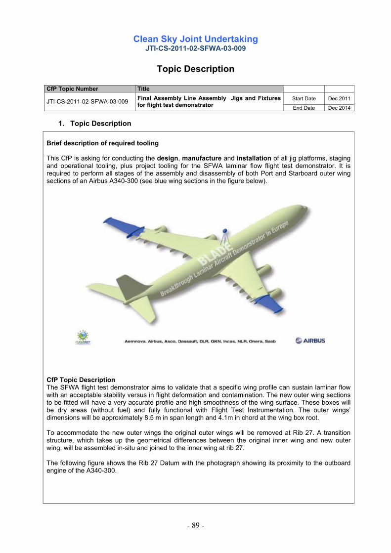
Clean Sky Joint Undertaking
JTI-CS-2011-02-SFWA-03-009
- 89 -
Topic Description CfP Topic Number Title
Start Date Dec 2011 JTI-CS-2011-02-SFWA-03-009 Final Assembly Line Assembly Jigs and Fixtures for flight test demonstrator End Date Dec 2014
1. Topic Description Brief description of required tooling This CfP is asking for conducting the design, manufacture and installation of all jig platforms, staging and operational tooling, plus project tooling for the SFWA laminar flow flight test demonstrator. It is required to perform all stages of the assembly and disassembly of both Port and Starboard outer wing sections of an Airbus A340-300 (see blue wing sections in the figure below).
CfP Topic Description The SFWA flight test demonstrator aims to validate that a specific wing profile can sustain laminar flow with an acceptable stability versus in flight deformation and contamination. The new outer wing sections to be fitted will have a very accurate profile and high smoothness of the wing surface. These boxes will be dry areas (without fuel) and fully functional with Flight Test Instrumentation. The outer wings’ dimensions will be approximately 8.5 m in span length and 4.1m in chord at the wing box root. To accommodate the new outer wings the original outer wings will be removed at Rib 27. A transition structure, which takes up the geometrical differences between the original inner wing and new outer wing, will be assembled in-situ and joined to the inner wing at rib 27. The following figure shows the Rib 27 Datum with the photograph showing its proximity to the outboard engine of the A340-300.

Clean Sky Joint Undertaking
JTI-CS-2011-02-SFWA-03-009
- 90 -
Key Inputs Upon selection of a preferred bidder the following information will be made available:
• Build philosophy for FAL operations
• Aircraft tolerance requirements
• Frontier drawings
• Wing models / drawings
Key Requirements Tooling requirements
Pre-Flight Test tooling to support a build philosophy which includes:- 1 - Disassembly and withdrawal of the existing outer wingbox at rib 27 datum. 2 - Assembly of new transition structure to inner wingbox. 3 - Wing join up of new outer wingbox to the assembled transition structure. Post-Flight Test tooling to support a build philosophy which includes:- 1 – Disassembly of the new outer wingbox from the transition structure. 2 – Disassembly of the new inner wingbox transition structure back to the original Rib 27 datum. 3 – Restore inner wingbox structure to rib 27 original condition. 4 – Wing join up to restore outer wingbox and inner wingbox to original condition. To facilitate disassembly & assembly operations, two rigid structural jig platform stages are required to be erected at both port and stbd wing positions for the purpose of supporting operational tooling and operator access. The interfaces of the structural jig platform and operational tooling will require to be qualified by laser tracking and positional setting to the airframe reference datums.

Clean Sky Joint Undertaking
JTI-CS-2011-02-SFWA-03-009
- 91 -
•Wing Twist
Maximum asymmetry final assembly: at Rib 28: 24’ at Rib 37: 40’ •Wing Pitch
Tolerance = +/-5’ •Wing Dihedral
Tolerance = +/-5’ •Wing Sweep
Tolerance = +/-2’30”, with maximum asymmetry of 2’ The image below illustrates the concept. It should be noted that separate jigs for both wings will be required simultaneously.
General
This preliminary specification is issued to enable potential applicants to submit costed proposals to the JU for the conception, design, manufacture and supply of the required tooling package. It will also be the responsibility of the applicant to install all tooling, platforms and associated staging to carry out the required operations at the Airbus Final Assembling Line facility Toulouse. All tooling should be finally qualified and supplied with detailed inspection reports. The work package also includes the requirement on the applicant to project manage all stages of supply and installation to meet technical requirements and project milestones.
Applicants must comply with the Airbus processes for tool design and manufacture (ME-Guide-11-522) which covers the design of new tooling from scheming through to production tool drawings and modifications to existing tool drawings, and which shall be provided to the successful applicant during the negotiation phase. Handling of customer technical tooling is not included in any of the commercial requirements that are covered within formal Purchase Order documentation and Tool Specification.

Clean Sky Joint Undertaking
JTI-CS-2011-02-SFWA-03-009
- 92 -
Lifting & Handling
All manufactured tooling must be compliant with existing Airbus standards and health & safety directives. The supplier should ensure that the design of any tooling takes into account the elimination or reduction of over-reaching, stretching and working overhead. Ease of loading of any component parts and the subsequent loading and un-loading of the completed assembly must be considered. Any tooling items that fall outside the Airbus weight limit (25kg) must be supplied with suitable lifting equipment. Particular attention must be given to removing weight where possible whilst still ensuring tooling functionality.
Tooling Design Tooling designs where possible should embrace innovative designs and new technologies for tooling solutions to achieve project cost reductions and improved efficiency of operations in keeping with a one off or low volume build.
Delivery
The applicant will have full responsibility and charge of transportation of all tooling to the FAL. Refer to section 3. Major deliverables and schedule.
Installation
The applicant will have full responsibility and charge of installation and certify the conformity of all jig platforms, stages and operational tooling with reports and quality documentation. Refer to section 3. Major deliverables and schedule. It is expected that all metrology equipment required for the setting, certification and acceptance of the jigs will be provided by the applicant.
Provisional Summary Table Listing Required Tooling. The following list has been defined from the preliminary build philosophy and will evolve as the build philosophy matures. The applicant will be expected to contribute to the build sequence and take ownership of the tool requirements.
Stage Type Item Description Comment
1 Aircraft Prep Jig 1.1 Jig Platform and staging - PORT
Rigid platform erected under wing to support items 2.1, 3.1 & 4.1. Also incorporates staging
Jig 1.2 Jig Platform and staging - STBD
Rigid platform erected under wing to support items 2.2, 3.2 & 4.2. Also incorporates staging
Staging 1.3 Staging Any additional staging not covered by above
2
MSN1 wing removal Jig 2.1 MSN1 Outer Wing Jig - PORT
Supports MSN1 outer wing during removal and refit
Jig 2.2 MSN1 Outer Wing Jig - STBD Supports MSN1 outer wing during removal and refit
Jig 2.3 MSN1 Outer Wing Separation jig - PORT
Tool to jack MSN1 wing apart after fasteners have been removed (used in
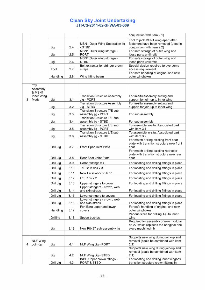
Clean Sky Joint Undertaking
JTI-CS-2011-02-SFWA-03-009
- 93 -
conjunction with item 2.1)
Jig 2.4 MSN1 Outer Wing Separation jig - STBD
Tool to jack MSN1 wing apart after fasteners have been removed (used in conjunction with item 2.2)
Jig 2.5 MSN1 Outer wing storage - PORT
For safe storage of outer wing and loose parts until refit
Jig 2.6 MSN1 Outer wing storage - STBD
For safe storage of outer wing and loose parts until refit
Tool 2.7 Bolt extractor for stringer crown straps
Special design required to overcome access requirement
Handling 2.8 Wing lifting beam For safe handling of original and new outer wingboxes
3
T/S Assembly & MSN1 Inner Wing Mods Jig 3.1
Transition Structure Assembly Jig - PORT
For in-situ assembly setting and support for join-up to inner wing
Jig 3.2 Transition Structure Assembly Jig - STBD
For in-situ assembly setting and support for join-up to inner wing
Jig 3.3 Transition Structure T/E sub assembly jig - PORT For sub assembly
Jig 3.4 Transition Structure T/E sub assembly jig - STBD For sub assembly
Jig 3.5 Transition Structure L/E sub assembly jig - PORT
To assemble in-situ. Associated part with item 3.1
Jig 3.6 Transition Structure L/E sub assembly jig - STBD
To assemble in-situ. Associated part with item 3.2
Drill Jig 3.7 Front Spar Joint Plate
For match drilling existing front spar plate with transition structure new front spar
Drill Jig 3.8 Rear Spar Joint Plate
For match drilling existing rear spar plate with transition structure new rear spar
Drill Jig 3.9 Corner fittings x 4 For locating and drilling fittings in place Drill Jig 3.10 T/E Stub ribs x 3 For locating and drilling fittings in place Drill Jig 3.11 New Falsework stub rib For locating and drilling fittings in place Drill Jig 3.12 L/E Ribs x 2 For locating and drilling fittings in place Drill Jig 3.13 Upper stringers to cover For locating and drilling fittings in place
Drill Jig 3.14 Upper stringers - crown, web and skin straps For locating and drilling fittings in place
Drill Jig 3.15 Lower stringers to covers For locating and drilling fittings in place
Drill Jig 3.16 Lower stringers - crown, web and skin straps For locating and drilling fittings in place
Handling 3.17 For lifting upper and lower covers
For safe handling of original and new outer wingboxes
Drilling 3.18 Spoon bushes Various sizes for drilling T/S to inner wing
Jig 3.19 New Rib 27 sub assembly jig
Required for assembly of new modular rib 27 which replaces the oringinal one piece machined rib
4 NLF Wing Join-up Jig 4.1 NLF Wing Jig - PORT
Supports new wing during join-up and removal (could be combined with item 2.1)
Jig 4.2 NLF Wing Jig - STBD
Supports new wing during join-up and removal (could be combined with item 2.1)
Drill Jig 4.3 INBD Upper crown fittings - PORT & STBD
For locating and drilling inner wingbox transition structure crown fittings in

Clean Sky Joint Undertaking
JTI-CS-2011-02-SFWA-03-009
- 94 -
place
Drill Jig 4.4 OUTBD Upper crown fittings - PORT & STBD
For locating and drilling outer wingbox crown fittings in place
Drill Jig 4.5 INBD Lower crown fittings - PORT & STBD
For locating and drilling inner wingbox transition structure crown fittings in place
Drill Jig 4.6 OUTBD Lower crown fittings - PORT & STBD
For locating and drilling outer wingbox crown fittings in place
Drill Jig 4.7 INBD corner fittings - PORT & STBD
For locating and drilling inner wingbox transition structure crown fittings in place
Drill Jig 4.8 OUTBD corner fittings - PORT & STBD
For locating and drilling outer wingbox crown fittings in place
Drill Jig 4.9 Crown fitting to Rib 28 interface - INBD Matched (mirrored) tooling
Drill Jig 4.10 Crown fitting to Rib 28 interface - OUTBD Matched (mirrored) tooling
Handling 4.11 Wing lifting beam As item 2.8
5 TBA
Post Join-Up Assembly & Systems Installation
6
Aero Fairing Assembly TBA
7 Plastron Assembly TBA
2. Special Skills, certification or equipment expected from the applicant • The applicant should have experience in aeronautical tooling: design and manufacturing. • The applicant should have experience in the assembly of aeronautical wing boxes. • The applicant should have good manufacturing and metrological skills in order to supply the required
tolerances. • The applicant should have fluent English manufacturing engineering language and communication skills. • The applicant should display a knowledge of innovative tooling methodologies which may provide solutions
to the unique issues posed by a laminar flow aircraft.
3. Major deliverables and schedule Del. Ref. Nr. Title Description Due date Supplier selection Sept 2011 Statement of work Defined tooling requirement & specification issue Oct 2011 Design Proposal - CDR Design proposal Critical Design Review Nov 2011 Scheme - CDR Design Scheme Critical Design Review and
compliance to Airbus ME-GUIDE-11-522 Jan 2012
Detail design Approvals and issue of drawings for manufacture June 2012 Manufacture Manufacture & acceptance of all required tooling Dec 2012 Delivery to site Jig platform, staging and operational tooling Jan 2013 Installation Commissioning and qualifying Jan 2013 Build Support Tooling support during wing build operations to flight
test date (Jan to Nov 2013) Jan 2013
Flight test (Dec 2013 to Jun 2014) Dec 2013 Aircraft refurbishment Tooling support during wing refurbishment operations
(Jun to Dec 2014) June 2014

Clean Sky Joint Undertaking
JTI-CS-2011-02-SFWA-03-009
- 95 -
Decommissioning Tooling withdrawal and storage/disposal Dec 2014
Data and report Completion of technical file, qualifying documentation, tool drawings and model data for vaulting/storage. Ref. ME-GUIDE-11-522
Dec 2014
Key Milestones and Dates
Start of wing removal Jan 2013 Start of transition structure April 2013 Start of wing join-up June 2013 Start of flight test Dec 2013 Aircraft refurbishment June 2014 Project completion Dec 2014
4. Topic value The total value of biddings for this work package shall not exceed
€ 2.000.000,-- [two million euros]
Please note that VAT is not applicable in the frame of the CleanSky program
5. Estimated spend profile (k€) 2009 2010 2011 2012 2013 2014 2015
400 1.000 600

Clean Sky Joint Undertaking
Call SP1-JTI-CS-2011-02 Systems for Green Operations
- 96 -
Clean Sky – Systems for Green Operations
Identification topics VALUE MAX FUNDJTI-CS-SGO 2 850.000 637.500JTI-CS-SGO-01JTI-CS-SGO-02 600.000JTI-CS-2011-2-SGO-02-034 600.000JTI-CS-SGO-03 JTI-CS-SGO-04 250.000JTI-CS-2011-2-SGO-04-003 250.000JTI-CS-SGO-05JTI-CS-TEV 0
ITD - AREA - TOPIC
Area-04 - Aircraft Demonstrators
EWIS safety analysis tool
Clean Sky - Systems for Green OperationsArea-01 - Definition of Aircraft Solutions and explotation strategiesArea-02 - Management of Aircraft Energy
Area-05 - Aircraft-level assessment and exploitationClean Sky - Technology Evaluator
Solid State Power Controllers test benches
Area-03 - Management of Trajectory and Mission

Clean Sky Joint Undertaking
JTI-CS-2011-2-SGO-02-034
- 97 -
Topic Description CfP Nbr Title Timeframe
End date 31.12.2014 JTI-CS-2011-2-SGO-02-034 EWIS Safety Analysis Tool Start date 01.11.2011
1. Background
Until just over a decade ago, internal electrical wiring was not considered a source of safety risks among civil aircraft fleet. But a series of fatal airplanes crashes in the span of just a few years quickly raised the visibility of wiring-related failures and alerted regulators to the critical nature of aircraft wiring. People learned that the wiring systems in aging planes might be leading to a dangerous situation. At this end, the US government Administration and the Federal Aviation Administration (FAA) have instructed the Aging Transport System Rulemaking Advisory Committee (ATSRAC) to investigate on this issue. The role of ATSRAC was to analyze the effects of aging transport systems, to develop and provide recommendations to mitigate them. The results of the ATSRAC final report have helped to provide new regulations on EWIS safety analysis, particularly on the FAR 25 and CS25 subpart H. Historically, safety analyses do not address the Electrical Wire Interconnect System (EWIS) failure fully or at all. In safety analyses that address EWIS failures directly, random EWIS failures are treated as basic events that enter into the bottom of system fault trees. The failures rates used are of the order of 1.0E-7/Flight hour (FH) (for both connector and wire failures). These rates come from standard reliability databases that are not aviation specific; therefore, their applicability to failures rates aboard aircraft is uncertain. Moreover, today’s jet aircraft relies even more on sophisticated electrical systems and computers, in which the reliability of wiring, power feeder cables, connectors, and circuit protection devices is crucial. Wiring is now seen as vital to systems that support an aircraft-level function, and wiring must be designed, modified, monitored, and maintained as such. As the CS25 section 1705 recommends, the EWIS must be considered as an important separate system, as important as hydraulic, pneumatic, structural, and other systems. During the last decade, there has been an evolving understanding of the importance of the EWIS in aircraft safety. Even though the new rules relating to EWIS, specifically CS25 Section 1709 and his Acceptance Means of Compliance (AMC) released on September 2008, give a flowchart method to assess the safety of an aircraft (based on the SAE ARP 4761), discussion continues about how the EWIS should be analyzed in an aircraft safety assessment. The safety assessment of the new aircrafts has to include the EWIS as a system, which must be analyzed. Today, we agreed that in order to respect this new regulation a good way to proceed is to use the existing safety tools. Nowadays, there are a lot of safety tools which are used to give or help to give a safety assessment in aviation.
2. Scope of work
This call for proposal aims to select a partner that will be in charge of the development of a methodology and tools aiming to give a safety analysis on the EWIS system of an aircraft. The EWIS Risk Analysis Tool will be done in strict respect of the CS 25 section 1705 and 1709 (this also needs the review and certification from the regulation authorities like FAA or EASA): “EWIS must be designed and installed so that: (a) Each catastrophic failure condition (1) is extremely improbable; and (2) does not result from a single failure; And (b) Each hazardous failure condition is extremely remote”

Clean Sky Joint Undertaking
JTI-CS-2011-2-SGO-02-034
- 98 -
Those high level requirements are mandatory requirements; they will be detailed in the first phases of the methodology development. The required analysis is based on a qualitative approach to assess EWIS safety as opposed to numerical method, probability-based quantitative analysis. The safety analysis must consider the effects that both physical and functional failures of EWIS would have on aircraft safety. The CS25 section 1709 means that for the EWIS, in terms of safety objectives, each catastrophic failure condition is under 1.0E-9/FH and will not result from a single failure. These are so unlikely failure conditions that they are not supposed to occur during the entire operational life of all aircrafts of one type. It also specifies that each hazardous failure condition is under 1.0E-7/FH. These are failure conditions that are not anticipated to occur to an individual aircraft during its total life but which may occur a few times when considering the total operational life of all aircrafts of the same type. To be effective, the EWIS Risk Analysis Tool will have to consider several input files and databases. The input files will contain the relevant parameters in terms of geometry, routing, zoning, bundling… The required structure of these xml inputs will be defined together by the applicant and the caller, whereas their content (corresponding to the use case(s)) will be given by the caller. The databases will contain relevant safety parameters of the wires, the systems they support, the bundles, the zones… The structure and the content of these xml files will be defined and filled-in together by the applicant and the caller. The databases won’t be specific to an aircraft type but rather generic as much as possible. The association of the tool, the inputs and the databases will allow the measurement of the level of importance of an EWIS failure, in terms of both severity and probability of effect, with respect to the continued safe operation of an aircraft. Users of the tool must be able to integrate the results of the EWIS analysis with the overall aircraft safety analysis. This will result in specific requirements in terms of output data: these additional requirements will be defined during the first phase of the development together by the applicant and the caller. In terms of complexity, the objective of the tool will be to address an entire aircraft EWIS. However, during the evaluation process, several more simple use cases will be used, with increasing levels of complexity (size). The first step will consist in the development of a method that will be used to assess the conditions. This method will have to be explained clearly before working on the tool itself (based on the AMC and the flowchart of the CS25 section 1709). The selected partner will have to show the good understanding of the standards requirements. He will also provide a report in which he will summarize the principal requirements and how he will respond to them. This report will also mention the needs and difficulties of the selected partner. The second step will consist in the development of the EWIS Risk Analysis Tool to assess the safety of the EWIS system in an aircraft. The idea is to start from an existing safety tool which has already performed avionic safety analysis and to develop additional module(s) specifically developed for the EWIS application. Then the EWIS databases will be integrated to the EWIS Risk Analysis Tool that will permit to give an automatic safety analysis of the EWIS (reports, estimations, graphics, charts, etc.). The selected partner has to consider that there can be several databases to integrate depending on the type of information and that those databases should be modifiable. The third step will consist in the verification and validation of the tool. The tests will be initially performed on simple use cases in order to be able to verify the analysis with simple tools (paper + Excel). Then the complexity will be addressed with more and more complex use cases and validation will be qualitative. The exact scope and method of validation will be defined during the development phase. Finally, the partner will provide assistance on its developed tool for 2 years after the completion of the tool. He will also perform the maintenance when required and develop minor updates when required. Of course, the exact scope of this “maintenance” will be defined together with the applicant, but it is asked to make a provision of several man-days for this part. At the end of the project, the tool will be co-owned by the applicant and the caller.

Clean Sky Joint Undertaking
JTI-CS-2011-2-SGO-02-034
- 99 -
3. Type of work
The selected partner shall deliver a methodology, a software tool and a user manual of the tool. The partner shall provide all the necessary resources (safety expert, respect of standards requirements, software expert, materials, etc.) to this proposal.
4. Special skills, certification or equipment expected from the applicant The partner should be used to work within the scope of the aviation standards and requirements and should demonstrate its ability to cope with the new FAA and EASA regulations: CS 25 subpart H, especially part 25.1709, 25.1309 and respective AMC. The partner should have a matured experience in safety (ARP 4761, ARP 4754, etc.). The partner should be experienced in simulation software tools. The partner should have his own recognized (by the aviation community) tool.
5. Major Deliverables and schedule Deliverable Title Description (if applicable) Due date D1 Preliminary Description method
(description of the method ) 31/12/2011
D2 Draft of the EWIS Risk Analysis Tool
31/07/2012
D3 Validation test plan 31/07/2012 D4 Validation test report 31/10/2012 D5 Final EWIS Risk Analysis Tool 31/12/2012
D6 User manual 31/12/2012 D7 Dissemination material Short presentation of the project for
dissemination purpose 31/12/2012
The period covering 31/12/2012 to 31/12/2014 will be dedicated to potential maintenance and minor updates of the tool.
6. Topic value (€)
The maximum value for this topic is 600k€* *Please note any proposal above this value will be NOT be eligible.
7. Remarks The EWIS inputs/databases containing EWIS electrical and physical data usable for the topic such as geometry and length of each cable, the system they support, bundles, zones, the routing of cables in the space reservation, the Bill of Material (BOM) of the wire harnesses, failure rates, etc will be defined together between the applicant and the caller. The format of the exchange files will be XML, as well should be the outputs format of the tool. The proposal should stipulate and address the analytical methodologies that are required as deliverables for certification: a. Airplane level Functional Hazards Analysis b. System level Functional Hazards Analysis c. Fault Tree Analysis d. Failure Mode and Effects Analysis e. Reports formatted to meet FAA/EASA expectations

Clean Sky Joint Undertaking
JTI-CS-2011-2-SGO-04-003
- 100 -
Topic Description
CfP Nbr Title
End date 31/12/2013 JTI-CS-2011-2-SGO-04-003 Solid State Power Controllers test benches Start date 01/11/2011
1. Background
The purpose of this call for proposal (CfP) is to design specific load test benches dedicated to the tests of Solid State Power Controllers (SSPC). These load test benches will be used to simulate a range of aircraft electrical loads in order to test different types of SSPCs. The interest and the need of these specific test benches are to give more confidence on the advanced distribution systems design. New SSPCs technologies drive to develop new tests benches technologies in order to be able to test the entire advanced distribution systems.
2. Scope of work The system tested using these load test benches are the new technologies SSPCs developed in the frame of the More Electrical Aircraft. The applicant shall be able to define specific benches test based on these characteristics. The following main functions and features shall be considered:
1) Load profiles shall be programmable from a specific computer. 2) Each channel shall be able to support either +/- 270 VDC, 230 VAC, 115 VAC and 28 VDC. 3) Each channel shall allow to set up a current consumption from 0 up to 15 A, with an accuracy
of 0,5 A and a slew rate of 1 ms. 4) A total of 80 channels are required, i.e. 80 physical inputs must be available. 5) The load bench shall be able to emulate A/C equipment power consumption on A/C electrical
network: three-phase 115VAC, three-phase 230VAC, 540VDC or .28VDC. 6) The total consumption of the load benches will be around 100 kW. 7) A maximum of five cabinets shall cover the 100 kW total power. 8) Each cabinet shall be used in a laboratory controlled environment (25°c). The cabinets shall
not require additional ventilation. The size of each cabinet shall not exceed the following dimensions: Height: 2000 mm, depth: 800 mm, width: 800 mm. The cabinet shall be moved inside buildings without specific tools.
9) The link between the cabinet and the monitoring & control computer shall be compatible with Ethernet network and with a distance between benches and monitoring & control of at least 30 m.
The applicant shall perform following main activities:
- Define adequate test benches technologies with the SGO member (end user), - Design, manufacture and validate the test benches, - Install the test benches at SGO member facilities, - Validate the test benches at SGO member facilities, - Training phase of SGO member technical user, - Ensure the maintenance of the means during the test campaign.

Clean Sky Joint Undertaking
JTI-CS-2011-2-SGO-04-003
- 101 -
3. Type of work Planning and deliveries A kick-off meeting, a progress meeting and final meeting will be scheduled at topic manager’s site. This project is split into following tasks proposed for the applicant activities: At T0 (assumed 01.11.2011): Kick of meeting: review of generic specification and planning Task 1: (T0+2M) Review of final detailed specification Task 2: (T0+5M) Design Review of test benches Task 3: (T0+12M) Installation of test benches in SGO member facilities Acceptance test report to validate the bench Technical training phase from applicant to SGO member in order it can operate the test bench autonomously. Task 4: (TO+25M) Maintenance of the means during the test campaign on SGO member facilities Task 5: (T0+26M) Final meeting to close this project Progress report will be requested every month. Documentation for installation and maintenance shall be delivered by the applicant.
4. Special skills, certification or equipment expected from the applicant For this study, the applicant shall satisfy following criteria:
• Strong experience in the field of industrial test bench design and manufacturing is mandatory, • ISO qualification for the design and manufacturing of industrial test benches is mandatory, • Experience and knowledge of electronic components test bench is a key factor, • Knowledge of RTCA-DO-160 standard and aeronautic environmental requirements is an advantage, • Innovative components technologies are encouraged if minimum of maturity is demonstrated in
equivalent test bench and if development risks are limited. • Insurance shall be provided to manage this work in time without delay for study and development
phases. • Available resources to execute the respective tasks should be stated in the proposal.
5. Major deliverables and schedule Deliverable Title Description
(if applicable) Due date
D1 - Compliance Matrix with final
technical specification. - Development plan.
January 2012
D2 - Design description and datasheet of test bench.
- Preliminary Drawing
March 2012
D3 - Manufactured test bench October 2012
D4 - Validation test report, - Delivery to SGO member facilities, - Installation and Acceptance test
report of test bench
November 2012
D5 - Drawing (test bench plan), user and maintenance manual.
December 2012
D6 - Dissemination document Short presentation of the
project for dissemination purpose
December 2013

Clean Sky Joint Undertaking
JTI-CS-2011-2-SGO-04-003
- 102 -
6. Topic value (€)
The maximum value for this topic is 250,000 €.*
(Two hundred fifty thousand euros) *Please note any proposal above this value will be NOT be eligible.
7. Remarks Only if applicable.

Clean Sky Joint Undertaking
Call SP1-JTI-CS-2011-02 Technology Evaluator
- 103 -
Clean Sky – Technology Evaluator
No topics in this call