calumet area hydrologic master plan (hmp) …
TRANSCRIPT
CALUMET AREA
CITY OF CHICAGO, COOK COUNTY, ILLINOIS
(DATA AND REFERENCES ARE ACCURATE UP TO JULY 2004)
PREPARED FOR:
CHICAGO DEPARTMENT OF ENVIRONMENT 30 NORTH LASALLE STREET – SUITE 2500
CHICAGO, ILLINOIS 60602
PREPARED BY:
V3 COMPANIES, LTD. 120 NORTH LASALLE STREET
CHICAGO, ILLINOIS 60602 312.419.1985
FUNDING PROVIDED BY:
CHICAGO DEPARTMENT OF ENVIRONMENT, ILLINOIS DEPARTMENT OF NATURAL RESOURCES C2000 PROGRAM,
U.S. DEPARTMENT OF HOUSING AND URBAN DEVELOPMENT, AND A SUPPLEMENTAL ENVIRONMENTAL PROJECT WITH CHICAGO SPECIALTIES.
.
AUGUST 2006
CALUMET AREA HYDROLOGIC
MASTER PLAN (HMP) EXECUTIVE SUMMARY
(VOLUME I)

Volume I V3 Companies of Illinois, Ltd. • i Calumet Area Hydrologic Master Plan August 2006
Primary Authors from V3 Companies of Illinois included; James Adamson, Shawn Arden, Christopher Bartosz, Didi Duma, Stuart Dykstra, Keith Oswald, Grant Van Bortel, Dan Wiseheart and Kristine Wright. Special thanks to the primary advisors involved with this project:
o Nicole Kamins Chicago Department of Environment
o Suzanne Malec Chicago Department of Environment
o Michael Miller Illinois State Geologic Survey (ISGS)
o Chris Pearson National Geodetic Survey
o George Roadcap Illinois State Water Survey (ISWS)
o Members of the Calumet Government Working Group
Thanks to the following landowners for providing site access:
o Waste Management, Inc.
o Metropolitan Water Reclamation District of Greater Chicago
o Illinois International Port District
Funds from the Supplemental Environmental Project with Chicago Specialties LLC were provided in connection with the settlement of enforcement actions taken by the U.S. EPA and the State of Illinois for alleged violations of environmental laws.

Volume I V3 Companies of Illinois, Ltd. • ii Calumet Area Hydrologic Master Plan August 2006
TABLE OF CONTENTS
EXECUTIVE SUMMARY ................................................................................................ 1
1. INTRODUCTION ..................................................................................................... 3
2. STUDY AREA SUMMARIES................................................................................... 5
2.1 Big Marsh .............................................................................................................. 6 2.2 Indian Ridge Marsh North ................................................................................... 12 2.3 Indian Ridge Marsh South................................................................................... 15 2.4 Heron Pond ......................................................................................................... 19 2.5 Deadstick Pond ................................................................................................... 22 2.6 Conservation Area............................................................................................... 27 2.7 Pullman Creek/Doty Ditch ................................................................................... 30 2.8 Hegewisch Marsh................................................................................................ 32 2.9 Van Vlissingen Prairie ......................................................................................... 34
3. SUMMARY ............................................................................................................ 36 GLOSSARY
EXHIBITS Exhibit 1: Aerial View of Calumet Area HMP Locations Exhibit 2: A & B: Calumet Area Watershed Atlases Exhibit 3: HMP Monitoring Locations Map

Volume I V3 Companies of Illinois, Ltd. • 1 Calumet Area Hydrologic Master Plan August 2006
EXECUTIVE SUMMARY
Hydrologic Master Plan (HMP) began during the development of the Calumet Area Ecological Management Strategy (EMS). As part of the EMS, a series of focus groups were held to discuss not only hydrology but also birds, fish, toxics, sediments, and more. When these focus groups identified their top priorities, studying the region’s hydrology often headed the list. As a result, funding was secured to begin this endeavor. Initial funds were provided by the Illinois Department of Natural Resources (IDNR) C2000 program. Funding was supplemented by the United States Department of Housing and Development (HUD), Supplemental Environmental Project with Chicago Specialties (SEP), and the City of Chicago. Due to the complexity of the project, various technical partners helped shape the project scope to maximize its usefulness. The Primary technical advisors throughout the project included George Roadcap of the ISWS and Michael Miller of the ISGS. The firm V3 Companies of Illinois, Ltd. (V3) was hired by the Chicago Department of Environment (DOE) to conduct the work and analysis. The Hydrologic Master Plan consists of a series of tasks (volumes) that assess, detail and characterize the hydrology, hydraulics and water quality of specific ecological management areas (EMAs) in the Calumet area watershed. These tasks include survey and mapping, water control structure assessments, hydraulic (stage/discharge) evaluations of control structures, watershed and sub-watershed boundary delineations, and water elevation/water quality monitoring. The purpose of the HMP is to provide hydrologic information to assist future investigators, planners and designers working to ecologically rehabilitate Calumet area open space parcels. The studied water bodies included Big Marsh, Indian Ridge Marsh North, Indian Ridge Marsh South, Lake Calumet, Heron Pond, Deadstick Pond, the Conservation Area, Pullman Creek (Doty Ditch), Hegewisch Marsh and Van Vlissingen Prairie. Hydrologic analyses of Hegewisch Marsh and Van Vlissingen Prairie are addressed in separate volumes (Volumes VII, VIII) since the timing and scope of their study differs; these sites were in a more advanced stage of planning, and were later added to the scope of the HMP. The combined HMP volumes provide a valuable compilation of information that begins to define the previously ill-defined Calumet hydrology within one comprehensive source. The information provided within the volumes helps us to understand defined drainage basins and how surface water drains throughout the study areas, and what type of structures or controls effect the water levels within the Ecological Management Areas (EMAs). The assessment of each significant control structure within the study areas provides information as to its current condition and functionality. Recommendations are provided for improvements to better control and predict water level behavior. Hydraulic modeling and detailed cross section surveys provide evaluations that assess whether the channels and control structures in the watershed contain the ability to convey significant storm events without flooding or significantly effecting water levels. These evaluations suggest improvements to more effectively convey storm event discharges and maintain water levels throughout the study area. The HMP also provides a one year monitoring record of water levels at the EMAs, which provides valuable insight into how the water bodies currently behave, fluctuate and respond to precipitation events. Groundwater elevations were recorded in a number of select locations throughout the Calumet area to better understand how groundwater Calumet area hydrology. Baseline water quality data is provided for select EMA sites to initiate an understanding of water quality and processes within each water body. Finally, the scope of the HMP established a strong geodetic survey data control system to ease the collection of future data to support upcoming ecological rehabilitation work.
Volume I V3 Companies of Illinois, Ltd. • 2 Calumet Area Hydrologic Master Plan August 2006
Recommendations are provided throughout these volumes to enhance hydrology and further develop the understanding of hydrologic processes and data gaps within the Calumet area. Recommendations include: • Implementing a series of outlet structure or hydrologic modifications to improve and
enhance hydrology of EMAs. Suggestions are made to conduct additional monitoring at select sites such as Pullman Creek (Doty Ditch).
• Conducting site specific hydrologic/hydrogeologic analyses on an as needed basis. • Continuing water level and water quality monitoring at select sites. Groundwater and
surface water interaction between Indian Ridge Marsh and Cluster Sites is poorly understood and needs to be evaluated to inform ecological rehabilitation plans.
• Conducting an investigation to evaluate sources of poor water quality. The Calumet Area Hydrologic Master Plan consists of eight (8) volumes. This document (Volume I) provides a summary of the framework of the HMP and summarizes the general findings specific to each individual water body. The outline of volumes is provided below:
Volume I Calumet Area Hydrologic Master Plan: Executive Summary Volume II Watershed Atlas and Stage-Discharge Rating Curves Volume III IDOT Pump Station #27 and Outlet Channel to Lake Calumet (Pullman
Creek/Doty Ditch) Volume IV Control Structure Assessment and Improvement Recommendations
Volume V Water Level Monitoring, Groundwater Seeps and Water Quality
Monitoring Report Volume VI Survey Control and Topographic Mapping Volume VII Hegewisch Marsh Hydrologic Analysis Volume VIII Van Vlissingen Prairie Hydrologic Analysis
Volume I V3 Companies of Illinois, Ltd. • 3 Calumet Area Hydrologic Master Plan August 2006
1. INTRODUCTION V3 has prepared the following report on behalf of the City of Chicago Department of Environment. This volume summarizes the scope and work product completed as the Calumet Area Hydrologic Master Plan. This volume also provides a fusion of the results and findings of the complete eight volumes or the Calumet Area Hydrologic Master Plan. The primary objective of the HMP is to develop a hydrologic framework that supports future ecological rehabilitation efforts and work of various technical advisors for projects throughout the Calumet area. To accomplish this goal, V3 performed a series of tasks and developed deliverables that include recommendations for hydrologic improvements. The Tasks included in the Calumet area Hydrologic Master Plan are outlined below, and are detailed in the proceeding volumes (Volumes II-VIII). Watershed and sub-watershed atlas V3 completed watershed boundary delineation for the Calumet area. Watershed boundaries and areas were delineated based upon topographic and watercourse divides as determined from V3 field surveys, DOE topographic survey base mapping, IDOT drainage studies, USGS topographic maps and Chicago Department of Water Management (DWM). The watershed and sub-watershed boundary atlases are provided in Volume II. Water control structure inventory, assessment and improvement recommendations V3 field evaluated and characterized the existing water control structures within each ecologic management area (EMA) and developed a priority matrix for improvement and maintenance recommendations. This inventory included review of seventeen (17) structures for functionality, adjustability, blockage potential and discharge capacity for extreme storm events. Volume III provides this information for Pullman Creek (Doty Ditch) and Volume IV contains the remaining analyses. Stage discharge curves for water control structures Following the evaluation and survey of water control structures and watershed basin characteristics, V3 prepared hydraulic models (stage discharge rating curves) for each of the major hydrologic basin control structures. These curves provide a tool to evaluate the hydraulic performance of structures and basins under a range of tailwater conditions. Additionally, these models provide information as to whether the structures function appropriately for the water basins. Volume II provides these assessments and interpretations. Hydraulic evaluation and recommendations for IDOT Pump Station #27 and outlet channel to Lake Calumet (Pullman Creek/Doty Ditch) V3 developed an assessment of watershed area, water control structures and culverts at Pullman Creek (Doty Ditch). In addition, V3 reviewed the Alvord, Burdick & Howson, L.L.C. (AB&H) study and summarized the results of the channel geometry and flood conveyance. This task also included a detailed analysis which included characterizing and modeling the functionality of IDOT pump station #27. These hydrologic factors were fused into an evaluation of ecologic and flood impacts of the current conditions at Pullman Creek (Doty Ditch). Various

Volume I V3 Companies of Illinois, Ltd. • 4 Calumet Area Hydrologic Master Plan August 2006
recommendations for future study and related rehabilitations efforts are provided. The detailed report is provided as Volume III. Water levels, seeps and water quality data over a one year period (July 2003-July 2004) This deliverable consists of the documented development and implementation of a water level monitoring network throughout the Phase I EMA sites. This includes the installation and monitoring of eight automatic staff gages, nine manual staff gages, four groundwater monitoring wells and three seeps. This information is displayed and summarized in Volume V in order to provide information as to how surface water and groundwater behave over a one year period. Water quality parameters (dissolved oxygen, specific conductance, temperature, oxidation-reduction potential, and pH) were collected on a monthly basis at staff gage locations in order to provide a baseline understanding of water quality characteristics and processes throughout the Calumet area. Survey control and topographic mapping Survey information provides the backbone for the HMP. This investigation developed a stable geodetic control from which all elevation data in this report is referenced. Additionally, the DOE LIDAR topographic map from the Phase I EMS study was evaluated and ground-truthed. The survey control includes a system of dependable benchmarks that will be used for standardizing future surveying efforts. V3’s topographic mapping tasks included developing bathymetric surveys of Deadstick Pond and Heron Pond, surveying drainage divides/overflow routes and stream/ditch profiles and presenting this information into a hydrological framework. Detailed Hydrologic Analysis and Monitoring for Hegewisch Marsh and Van Vlissingen Prairie Detailed hydrologic analyses and monitoring were conducted for Hegewisch Marsh and Van Vlissingen Prairie to assist in on-going ecological management planning at these sites. Tasks included surface water and groundwater monitoring for a one year period, continuous simulation surface water modeling, watershed boundary delineation, and an evaluation of groundwater/surface water interactions. Recommendations are made to optimize site hydrology to meet ecological habitat criterion. These analyses are provided in Volume VII and Volume VIII.

Volume I V3 Companies of Illinois, Ltd. • 5 Calumet Area Hydrologic Master Plan August 2006
2. STUDY AREA SUMMARIES Site summaries are provided that illustrate the findings and general conclusions on a site by site basis for the HMP. Exhibits 1 and 2 are provided at the end of report, and reference the EMA sites of the HMP. Exhibit 1 provides an overview aerial identifying all of the sites within this study. Exhibit 2 illustrates the watershed and sub-watershed atlas of the Calumet area. Lastly, Exhibit 3 illustrates the control structure and monitoring station locations referenced within this report. All water body acreages referred to in this volume were calculated using GIS and all site specific aerial photographs used within Volume I are dated 2004.
Volume I V3 Companies of Illinois, Ltd. • 6 Calumet Area Hydrologic Master Plan August 2006
*Refer to legend for all site specific maps.
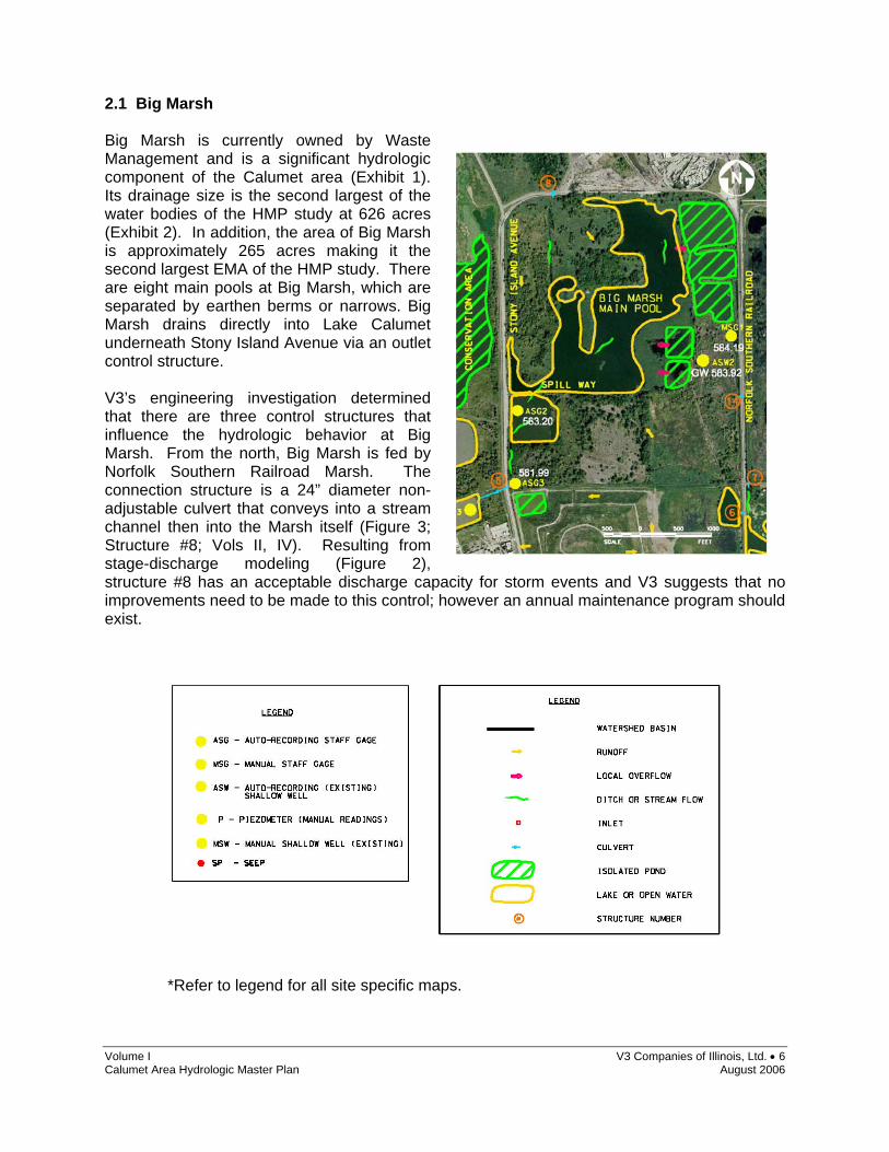
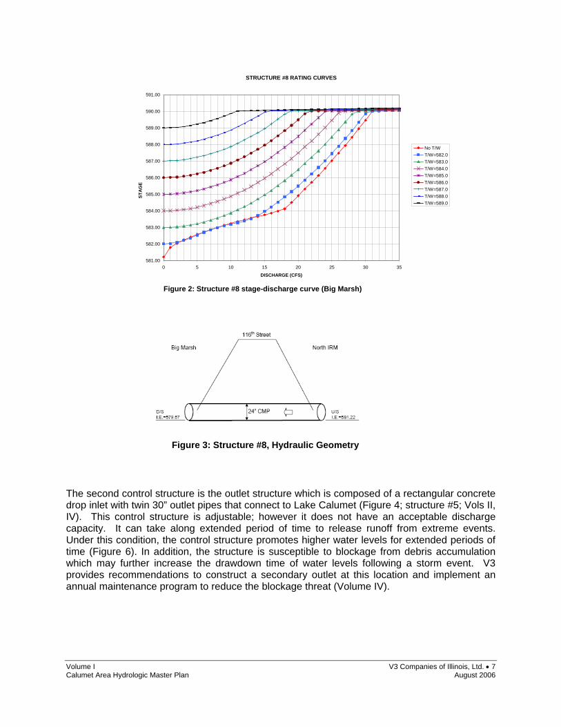
2.1 Big Marsh Big Marsh is currently owned by Waste Management and is a significant hydrologic component of the Calumet area (Exhibit 1). Its drainage size is the second largest of the water bodies of the HMP study at 626 acres (Exhibit 2). In addition, the area of Big Marsh is approximately 265 acres making it the second largest EMA of the HMP study. There are eight main pools at Big Marsh, which are separated by earthen berms or narrows. Big Marsh drains directly into Lake Calumet underneath Stony Island Avenue via an outlet control structure. V3’s engineering investigation determined that there are three control structures that influence the hydrologic behavior at Big Marsh. From the north, Big Marsh is fed by Norfolk Southern Railroad Marsh. The connection structure is a 24” diameter non-adjustable culvert that conveys into a stream channel then into the Marsh itself (Figure 3; Structure #8; Vols II, IV). Resulting from stage-discharge modeling (Figure 2), structure #8 has an acceptable discharge capacity for storm events and V3 suggests that no improvements need to be made to this control; however an annual maintenance program should exist.
Volume I V3 Companies of Illinois, Ltd. • 7 Calumet Area Hydrologic Master Plan August 2006
The second control structure is the outlet structure which is composed of a rectangular concrete drop inlet with twin 30” outlet pipes that connect to Lake Calumet (Figure 4; structure #5; Vols II, IV). This control structure is adjustable; however it does not have an acceptable discharge capacity. It can take along extended period of time to release runoff from extreme events. Under this condition, the control structure promotes higher water levels for extended periods of time (Figure 6). In addition, the structure is susceptible to blockage from debris accumulation which may further increase the drawdown time of water levels following a storm event. V3 provides recommendations to construct a secondary outlet at this location and implement an annual maintenance program to reduce the blockage threat (Volume IV).
STRUCTURE #8 RATING CURVES
581.00
582.00
583.00
584.00
585.00
586.00
587.00
588.00
589.00
590.00
591.00
0 5 10 15 20 25 30 35
DISCHARGE (CFS)
No T/WT/W=582.0T/W=583.0T/W=584.0T/W=585.0T/W=586.0T/W=587.0T/W=588.0T/W=589.0
STA
GE
Figure 2: Structure #8 stage-discharge curve (Big Marsh)
Figure 3: Structure #8, Hydraulic Geometry

Volume I V3 Companies of Illinois, Ltd. • 8 Calumet Area Hydrologic Master Plan August 2006
STRUCTURE #5 RATING CURVES
580
581
582
583
584
585
586
587
588
589
590
0 5 10 15
DISCHARGE (CFS)
STA
GE
T/W=580.0T/W=581.0T/W=582.0T/W=583.0
Figure 4: Structure #5, Hydraulic Geometry
Figure 5: Structure #5, looking North
Figure 6: Structure #5, stage-discharge curve (Big Marsh)

Volume I V3 Companies of Illinois, Ltd. • 9 Calumet Area Hydrologic Master Plan August 2006
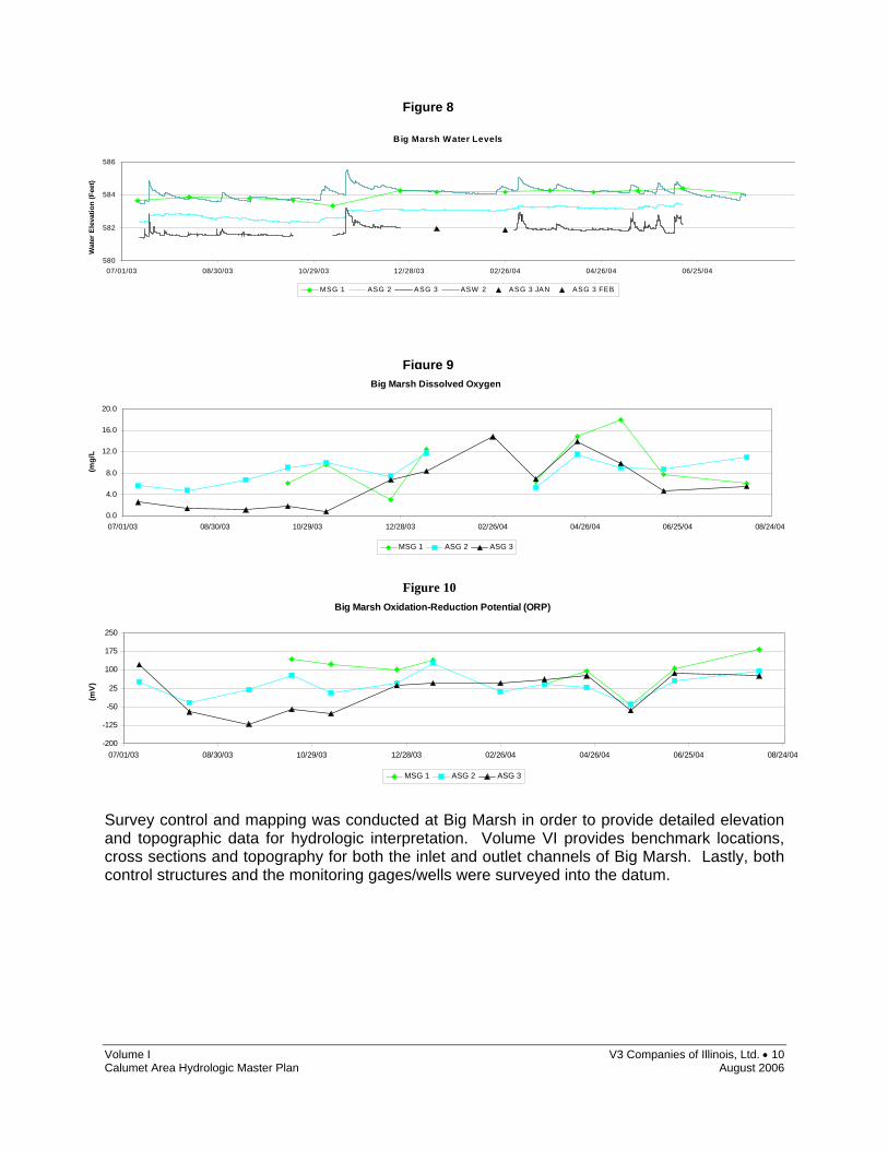
The final control structure is #14 and is a single non-adjustable 12” diameter culvert that drains 62 acres and regulates discharge from the Coke Plant to Big Marsh (Figure 7). Stage discharge relationships were developed and determined that the structure functions as designed and has an acceptable discharge capacity, the only recommendation for structure # 14 is to designate an annual maintenance program of the culvert (Volume IV). As detailed in Volume V (Water Level Monitoring, Groundwater Seeps and Water Quality Monitoring Report), V3 et al. monitored water levels and water quality at Big Marsh for a one year period. The water elevation data shows that the main pool at Big Marsh (ASG 2) is usually over a foot higher than the water at the outlet (ASG 3; Figure 8). During precipitation events, the outlet location backs up, taking significant time to drawdown. The East pools (MSG 1) of Big Marsh are always at a higher elevation than the main pool and outlet. Groundwater represented by ASW 2 (Figure 8) is responsive to precipitation events indicating a significant gross permeability of the aquifer medium, additionally groundwater elevations to the east of the main pool were always at least a foot higher than the Big Marsh main pool indicating groundwater feeds the marsh and flow is from the east. Some constituents of water quality at the Big Marsh outlet were poor. Dissolved oxygen at the Big Marsh outlet was consistently much lower than the remaining marsh (Figure 9), and was recorded at levels of concern for aquatic health (Figure 9). The oxidation/reduction potential of the water at the outlet also recorded reducing conditions for most of the year (Figure 10). V3 recommends a further detailed site specific water quality and groundwater investigation; however, this work should be conducted on an as needed basis when ecological objectives of Big Marsh have been defined.
Figure 7: Structure #14, Hydraulic Geometry
Volume I V3 Companies of Illinois, Ltd. • 10 Calumet Area Hydrologic Master Plan August 2006
Survey control and mapping was conducted at Big Marsh in order to provide detailed elevation and topographic data for hydrologic interpretation. Volume VI provides benchmark locations, cross sections and topography for both the inlet and outlet channels of Big Marsh. Lastly, both control structures and the monitoring gages/wells were surveyed into the datum.
Big Marsh Water Levels
580
582
584
586
07/01/03 08/30/03 10/29/03 12/28/03 02/26/04 04/26/04 06/25/04
Wat
er E
leva
tion
(Fee
t)
MSG 1 ASG 2 ASG 3 ASW 2 ASG 3 JAN ASG 3 FEB
Big Marsh Dissolved Oxygen
0.0
4.0
8.0
12.0
16.0
20.0
07/01/03 08/30/03 10/29/03 12/28/03 02/26/04 04/26/04 06/25/04 08/24/04
(mg/
L
MSG 1 ASG 2 ASG 3
Big Marsh Oxidation-Reduction Potential (ORP)
-200
-125
-50
25
100
175
250
07/01/03 08/30/03 10/29/03 12/28/03 02/26/04 04/26/04 06/25/04 08/24/04
(mV
)
MSG 1 ASG 2 ASG 3
Figure 8
Figure 9
Figure 10
Volume I V3 Companies of Illinois, Ltd. • 11 Calumet Area Hydrologic Master Plan August 2006
The overall HMP recommendations for Big Marsh are summarized below:
o An annual structure maintenance program should be enacted for all structures at Big Marsh (Structures #5, #8, #14) (Volume IV).
o Construct a secondary outlet at the location of structure #5 to reduce drawdown times of Big
Marsh (Volume IV).
o Conduct a further detailed site specific water quality and groundwater investigation; however, this work should be conducted on an as needed basis when ecological objectives of Big Marsh have been defined.

Volume I V3 Companies of Illinois, Ltd. • 12 Calumet Area Hydrologic Master Plan August 2006
2.2 Indian Ridge Marsh North Indian Ridge Marsh North (IRM North) is approximately a 114 acre parcel consisting of several pools separated by earth berms or narrow corridor channels. Its location is north of 122nd street and west of Torrence Avenue; the western boundary of Indian Ridge Marsh North is the Norfolk/Southern Railroad tracks (Exhibit 1). The drainage size of Indian Ridge Marsh North is 185 acres at its outlet, which includes an inlet from the adjacent coke plant. The marsh drains into Indian Ridge Marsh South under 122nd street via an outlet control structure (Exhibit 2). V3’s engineering investigation determined that there are two control structures that influence the hydrologic behavior at Indian Ridge Marsh North. From the north a culvert drains areas of the Coke plant into the marsh. The connection consists of a 36” non-adjustable culvert that conveys approximately 62 acres of drainage area into Indian Ridge Marsh North (Figure 11; Structure #7; Vols II, IV). A detailed drainage investigation of the coke plant was not conducted and it is unknown which areas of thee coke plant drain to the culvert. Stage/discharge modeling indicated that this structure has an acceptable discharge capacity for storm events, and no improvement recommendations are made except for the implementation of an annual maintenance program. It is unknown whether this culvert is managed by the owners of the adjacent coke plant.
The second control structure is the outlet which is an inlet box and attached 24” culvert (Figure 12; Structure #3, Vols II, and IV). The box rim sets the normal water level for the primary pool of Indian Ridge Marsh North. Through hydrologic modeling, V3 determined that this structure safely releases storm volumes; however, improvement recommendations are made due to the structure’s tendency to become blocked, which restricts flows and influences water elevations (Volume IV). In 2001, Harza Inc. repaired the outlet and it was apparent that beaver levelers may be required at this location. In addition, the culvert pipe is believed to be from the 1920’s and may be rusted and partially collapsed. V3 recommends inspecting and rehabilitating the
Figure 11: Structure #7, Hydraulic Geometry

Volume I V3 Companies of Illinois, Ltd. • 13 Calumet Area Hydrologic Master Plan August 2006
culvert, replacing the manhole with a water level control structure and installing a beaver leveler. Structure #3 should also have an annual maintenance program enacted.
Volume V details the water level, seeps and water quality monitoring program at Indian Ridge Marsh North. Figure 19 shows the water elevations collected for the entire Indian Ridge Marsh site. One automatic staff gage (ASG 4), four manual staff gages (MSGs) and two piezometers (P) were installed in order to monitor water elevations of separate pools and their relationship to groundwater. The side pools at Indian Ridge Marsh North represented by MSGs 4, 5, 6 and 7 are always at a higher elevation than the main pool (ASG 4; Figure 19) Groundwater elevations (P1 & P2; Figure 19) indicate that the marsh has a significant groundwater contribution that varies seasonally. Water elevation data and conductivity measurements suggest that the side pools have a higher component of surface water in their water budget than the main pool. Water elevations in the main pool fluctuated 1.05 feet during a one year monitoring period while the side pools fluctuated up to 1.6 feet (Figure 19). The water elevation data from the outlet of Indian Ridge Marsh North suggests that outlet blockage can influence changes in normal water levels for significant periods of time. Groundwater seepage was not directly observed during field investigations; however, it is believed that it may occur in unquantifiable amounts from the west (Cluster Sites). Water quality monitoring indicated that pH is alkaline, possibly due to slag influence (Figure 17), dissolved oxygen was safe for aquatic health (Figure 18) and specific conductance is stable indicating a groundwater influence. Water elevation and water quality data from Indian Ridge Marsh North are graphically displayed in the following section. V3 recommends a hydrogeologic study of Indian Ridge Marsh North to investigate the influence of the Cluster Sites (West of IRM North) and the magnitude groundwater influences at the site. Survey control and mapping was conducted at Indian Ridge Marsh North to provide detailed elevation and topographic data needed to execute the hydrologic interpretation. Volume VI provides detailed topography of the inlet and outlet locations in addition to possible overflow locations on the berms between pools. Both structures and all of the gages/wells utilized in this investigation were surveyed into the project datum.
Figure 12: Structure #3 Hydraulic Geometry (Indian Ridge Marsh North)
Figure 13: Structure #3, facing North

Volume I V3 Companies of Illinois, Ltd. • 14 Calumet Area Hydrologic Master Plan August 2006
The overall HMP recommendations for Indian Ridge Marsh North are summarized below:
o An annual structure maintenance program should be enacted for all structures at Indian Ridge Marsh North (Structures #3, #7) (Volume IV).
o At Structure #3, V3 recommends inspecting and rehabilitating the culvert, replacing the manhole
with a water level control structure and installing a beaver leveler.
o V3 recommends a hydrogeologic study of Indian Ridge Marsh North and its surroundings to investigate the influence of the Cluster Sites (West of IRM North) and the magnitude groundwater influences to the site.

Volume I V3 Companies of Illinois, Ltd. • 15 Calumet Area Hydrologic Master Plan August 2006
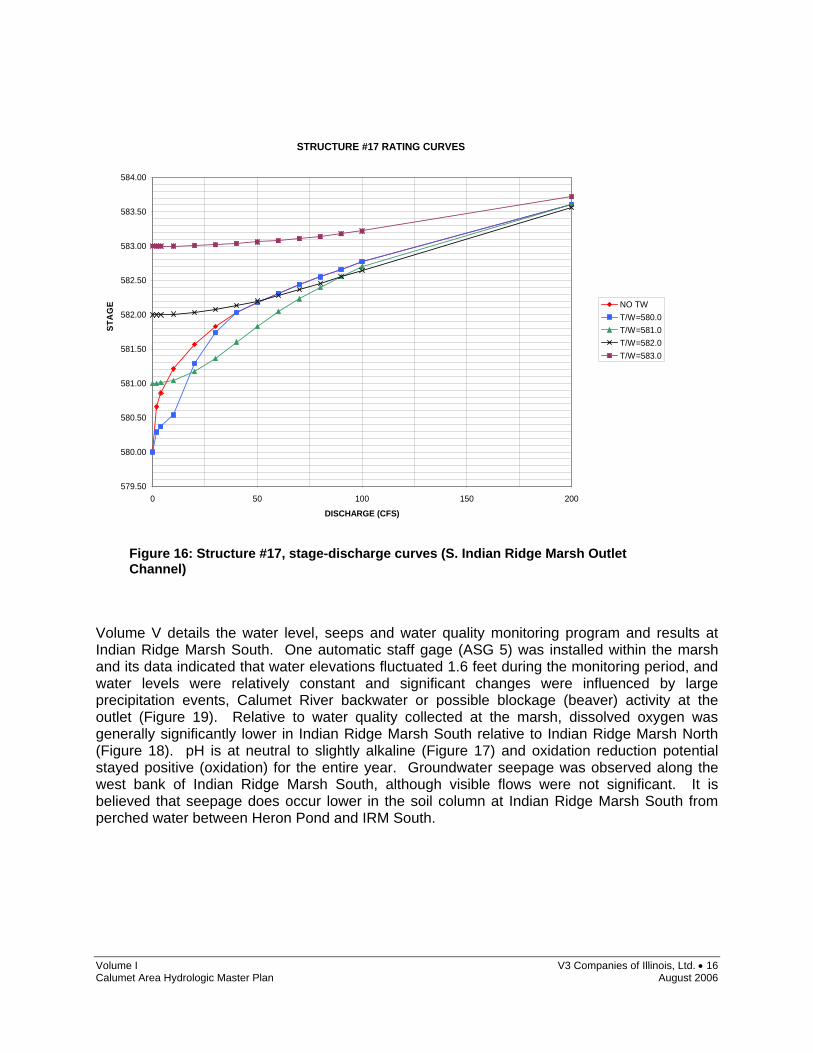
2.3 Indian Ridge Marsh South Indian Ridge Marsh South (IRM South) is currently owned by the City of Chicago and is located directly south and downstream of Indian Ridge Marsh North (Exhibit 1). The tributary area of IRM South at its outlet is 232 acres which includes the tributary of IRM North and portions of the coke plant. The surface water area is approximately 40 acres, which is made up of a straight elongated channel that flows from north to south and empties into the Calumet River via open channel with no control structure (Exhibit 2). V3’s engineering investigation determined that the primary inlet to Indian Ridge Marsh South is the conveyance of water from Indian Ridge Marsh North through the control structure (Figures 12 & 13; Structure #3). Section 2.2 details structure #3 and outlines the improvement recommendations. The outlet of Indian Ridge Marsh South is simply an open channel with no control structure; hence the main control of water elevations in the marsh is the channel outlet bottom and the channel’s ability to convey storm event discharges (Figures 14 & 15; Structure #17). Additionally, tail water of the Calumet River could play a role in water elevations during very significant storm events. The stage/discharge curves for this structure are provided in Figure 16. V3 recommends installing a concrete weir with stop logs at this outlet location, so that discharge and water levels can be better controlled to suit future ecological management decisions (Volumes II & IV).
Figure 15: S. Indian Ridge Marsh Outlet Channel, facing North
Figure 14: Structure #17, outlet channel from Indian Ridge Marsh South
Volume I V3 Companies of Illinois, Ltd. • 16 Calumet Area Hydrologic Master Plan August 2006
STRUCTURE #17 RATING CURVES
579.50
580.00
580.50
581.00
581.50
582.00
582.50
583.00
583.50
584.00
0 50 100 150 200
DISCHARGE (CFS)
NO TWT/W=580.0T/W=581.0T/W=582.0T/W=583.0
STA
GE
Volume V details the water level, seeps and water quality monitoring program and results at Indian Ridge Marsh South. One automatic staff gage (ASG 5) was installed within the marsh and its data indicated that water elevations fluctuated 1.6 feet during the monitoring period, and water levels were relatively constant and significant changes were influenced by large precipitation events, Calumet River backwater or possible blockage (beaver) activity at the outlet (Figure 19). Relative to water quality collected at the marsh, dissolved oxygen was generally significantly lower in Indian Ridge Marsh South relative to Indian Ridge Marsh North (Figure 18). pH is at neutral to slightly alkaline (Figure 17) and oxidation reduction potential stayed positive (oxidation) for the entire year. Groundwater seepage was observed along the west bank of Indian Ridge Marsh South, although visible flows were not significant. It is believed that seepage does occur lower in the soil column at Indian Ridge Marsh South from perched water between Heron Pond and IRM South.
Figure 16: Structure #17, stage-discharge curves (S. Indian Ridge Marsh Outlet Channel)

Volume I V3 Companies of Illinois, Ltd. • 17 Calumet Area Hydrologic Master Plan August 2006
Survey control and mapping was conducted to help execute the hydrologic deliverables at the marsh, this survey information is presented in Volume IV. Cross sections and detailed topography of the entire Indian Ridge Marsh South outlet channel are provided. Additionally, the gage used for monitoring and the control structure were surveyed into the project datum. The overall HMP recommendations for Indian Ridge Marsh South are summarized below:
o An annual structure maintenance program should be enacted for all structures at Indian Ridge Marsh South (Structures #3, #17) (Volume IV).
o At Structure #3, V3 recommends inspecting and rehabilitating the culvert, replacing the manhole
with a water level control structure and installing a beaver leveler (Volume IV).
o At Structure #17, V3 recommends installing a concrete weir with stop logs, so that discharge and water levels can be better controlled to suit future ecological management decisions.
Indian Ridge Marsh pH
4.0
6.0
8.0
10.0
12.0
07/01/03 08/30/03 10/29/03 12/28/03 02/26/04 04/26/04 06/25/04 08/24/04
pH
MSG 6 ASG 4 ASG 5
Indian Ridge Marsh Dissolved Oxygen
0.0
4.0
8.0
12.0
16.0
20.0
07/01/03 08/30/03 10/29/03 12/28/03 02/26/04 04/26/04 06/25/04 08/24/04
(mg/
L
MSG 6 ASG 4 ASG 5
Figure 17
Figure 18

Volume I V3 Companies of Illinois, Ltd. • 18 Calumet Area Hydrologic Master Plan August 2006
Indian
Ridge
Marsh
Water
Levels
580581583584585586 07/01/
0308/
30/03
10/29/
0312/
28/03
02/26/
0404/
26/04
06/25/
0408/
24/04
WaterElevation(Feet)
MSG 4
MSG 5
MSG 6
MSG 7
ASG 4
ASG 5
P 1P 2
Figure 19: Indian Ridge Marsh Surface Water and Groundwater Elevations (note: groundwater elevations higher than surface water indicates that surface water bodies may be fed by groundwater during parts of the year).
Volume I V3 Companies of Illinois, Ltd. • 19 Calumet Area Hydrologic Master Plan August 2006
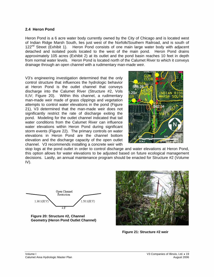
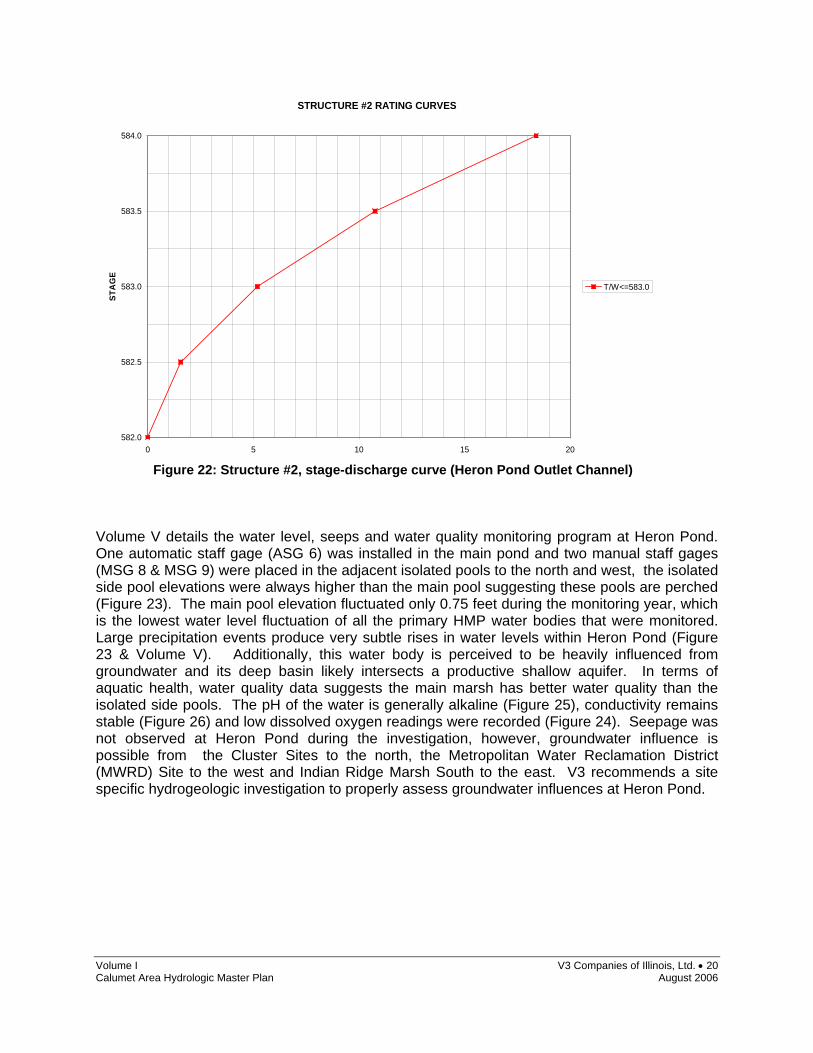
2.4 Heron Pond Heron Pond is a 6 acre water body currently owned by the City of Chicago and is located west of Indian Ridge Marsh South, lies just west of the Norfolk/Southern Railroad, and is south of 122nd Street (Exhibit 1). Heron Pond consists of one main large water body with adjacent detached and isolated pools located to the west of the main pond. Heron Pond drains approximately 105 acres (Exhibit 2) at its outlet and the pond basin reaches 10 feet in depth from normal water levels. Heron Pond is located north of the Calumet River to which it conveys drainage through an open channel with a rudimentary man-made weir. V3’s engineering investigation determined that the only control structure that influences the hydrologic behavior at Heron Pond is the outlet channel that conveys discharge into the Calumet River (Structure #2, Vols II,IV; Figure 20). Within this channel, a rudimentary man-made weir made of grass clippings and vegetation attempts to control water elevations in the pond (Figure 21), V3 determined that the man-made weir does not significantly restrict the rate of discharge exiting the pond. Modeling for the outlet channel indicated that tail water conditions from the Calumet River can influence water elevations within Heron Pond during significant storm events (Figure 22). The primary controls on water elevations in Heron Pond are the channel bottom elevation and the discharge capacity of the open outlet channel. V3 recommends installing a concrete weir with stop logs at the pond outlet in order to control discharge and water elevations at Heron Pond, this option allows for water elevations to be adjusted based on future ecological management decisions. Lastly, an annual maintenance program should be enacted for Structure #2 (Volume IV).
Figure 20: Structure #2, Channel Geometry (Heron Pond Outlet Channel)
Figure 21: Structure #2 weir
Volume I V3 Companies of Illinois, Ltd. • 20 Calumet Area Hydrologic Master Plan August 2006
Volume V details the water level, seeps and water quality monitoring program at Heron Pond. One automatic staff gage (ASG 6) was installed in the main pond and two manual staff gages (MSG 8 & MSG 9) were placed in the adjacent isolated pools to the north and west, the isolated side pool elevations were always higher than the main pool suggesting these pools are perched (Figure 23). The main pool elevation fluctuated only 0.75 feet during the monitoring year, which is the lowest water level fluctuation of all the primary HMP water bodies that were monitored. Large precipitation events produce very subtle rises in water levels within Heron Pond (Figure 23 & Volume V). Additionally, this water body is perceived to be heavily influenced from groundwater and its deep basin likely intersects a productive shallow aquifer. In terms of aquatic health, water quality data suggests the main marsh has better water quality than the isolated side pools. The pH of the water is generally alkaline (Figure 25), conductivity remains stable (Figure 26) and low dissolved oxygen readings were recorded (Figure 24). Seepage was not observed at Heron Pond during the investigation, however, groundwater influence is possible from the Cluster Sites to the north, the Metropolitan Water Reclamation District (MWRD) Site to the west and Indian Ridge Marsh South to the east. V3 recommends a site specific hydrogeologic investigation to properly assess groundwater influences at Heron Pond.
STRUCTURE #2 RATING CURVES
582.0
582.5
583.0
583.5
584.0
0 5 10 15 20
DISCHARGE (CFS)
STA
GE
T/W<=583.0
Figure 22: Structure #2, stage-discharge curve (Heron Pond Outlet Channel)

Volume I V3 Companies of Illinois, Ltd. • 21 Calumet Area Hydrologic Master Plan August 2006
Heron Pond Water Levels
580
582
584
586
588
590
07/01/03 08/30/03 10/29/03 12/28/03 02/26/04 04/26/04 06/25/04 08/24/04
Wat
er E
leva
tion
(Fee
t)
MSG 8 MSG 9 ASG 6
Heron Pond Dissolved Oxygen
0.0
4.0
8.0
12.0
16.0
20.0
07/01/03 08/30/03 10/29/03 12/28/03 02/26/04 04/26/04 06/25/04 08/24/04
(mg/
L)
MSG 9 ASG 6
Heron Pond pH
4.0
6.0
8.0
10.0
07/01/03 08/30/03 10/29/03 12/28/03 02/26/04 04/26/04 06/25/04
pH
MSG 9 ASG 6
Heron Pond Specific Conductance
0
500
1000
1500
2000
2500
7/1/2003 8/30/2003 10/29/2003 12/28/2003 2/26/2004 4/26/2004 6/25/2004 8/24/2004
(-uS/
cm)
MSG 9 ASG 6
Figure 23: Heron Pond Water Levels
Figure 24: Heron Pond Dissolved Oxygen
Figure 25: Heron Pond pH
Figure 26: Heron Pond Specific Conductance
Volume I V3 Companies of Illinois, Ltd. • 22 Calumet Area Hydrologic Master Plan August 2006
Survey control and mapping was conducted at Heron Pond in order to produce the hydrologic interpretation of the site. This survey data and figures are provided in Volume VI. A detailed bathymetric survey including adjacent land, banks and the outlet channel is provided for Heron Pond. Lastly, the gage used for monitoring was installed into the project datum. The overall HMP recommendations for Heron Pond are summarized below:
o An annual structure maintenance program should be enacted for the structure at Heron Pond (Structure #2) (Volume IV).
o At Structure #2, V3 recommends installing a concrete weir with stop logs, so that discharge and
water levels can be better controlled at Heron Pond to suit future ecological management decisions.
o V3 recommends a site specific hydrogeologic investigation to properly assess groundwater flow
directions around Heron Pond, and evaluate possible influences with Cluster Sites located to the North of Heron Pond.
o V3 recommends a further detailed water quality study in order to further establish aquatic health
conditions at Heron Pond.

Volume I V3 Companies of Illinois, Ltd. • 23 Calumet Area Hydrologic Master Plan August 2006
2.5 Deadstick Pond Deadstick Pond is approximately a 23 acre elongated water body that runs along the east side of Stony Island Avenue, south of 122nd Street (Exhibit 1). Deadstick Pond is owned and managed by the Metropolitan Water Reclamation District (MWRD). The pond averages 5 feet in depth from normal water levels, and reaches up to 10 feet in depth. The water body conveys to an outlet channel that flows south into the Calumet River through an outlet control structure. The drainage area of Deadstick Pond is approximately 90 acres and is the smallest drainage area of the water bodies studied in this investigation (Exhibit 2). V3’s engineering investigation evaluated the outlet structure that regulates Deadstick Pond discharge into the Calumet River (Figure 27; Structure #1; Vols II, IV). The structure is an adjustable rectangular concrete box structure with adjustable stop logs (Figures 27 & 28). The box is connected to an 18” culvert that conveys discharge into the Calumet River. Under low flow conditions, the water elevations in Deadstick Pond are controlled by the stop logs. During higher flow conditions the water elevations are controlled by the discharge capacity of the outlet pipe and tail water conditions from the Calumet River. Figure 29 shows hydraulic stage/discharge modeling conducted by V3 suggests that this outlet control structure has an acceptable discharge capacity for large storm events and does not appear to be susceptible to blockage (Volume II, IV). V3 recommends clearing the outfall channel of structure #1 and stabilizing the banks with rip-rap in addition to an annual maintenance program for structure #1.

Volume I V3 Companies of Illinois, Ltd. • 24 Calumet Area Hydrologic Master Plan August 2006
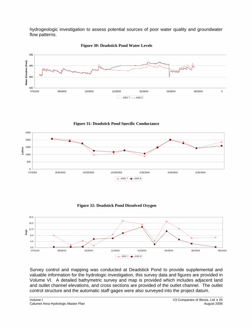
Volume V describes the water level, seeps and water quality monitoring program at Deadstick Pond. Two automatic staff gages (ASG 7 & ASG 8) monitored the water elevations and the gradient between the main pond and the outlet location for a one year period. Deadstick Pond fluctuated only 1.09 feet during the one year monitoring period and a slight gradient exists between the main pool (ASG 7) and the outlet channel (ASG 8) (Figure 30). The pond is responsive to precipitation events, as elevations were seen to increase up to a foot following large storm periods. Deadstick Pond recorded the highest specific conductance values within the HMP network (Figure 31), suggesting that the water is rich in dissolved minerals possibly due to a large groundwater influence (further studies required to assess groundwater flow direction and volume). Deadstick Pond also recorded the lowest dissolved oxygen levels (Figure 32), some measurements were below acceptable aquatic health standards. Seepage activity was monitored on the west bank of the pond; however no measurable observations were made. V3 recommends a water quality study in conjunction with a site specific
STRUCTURE #1 RATING CURVES
584.00
585.00
586.00
587.00
588.00
589.00
590.00
0 5 10 15 20 25 30
DISCHARGE (CFS)
STAGE
T/W<=582.3T/W=583.0
Figure 27: Structure #1, Hydraulic Geometry
Figure 28: Structure #1, facing North
Figure 29: Structure #1, stage-discharge curves (Deadstick Pond Outlet)
Volume I V3 Companies of Illinois, Ltd. • 25 Calumet Area Hydrologic Master Plan August 2006
hydrogeologic investigation to assess potential sources of poor water quality and groundwater flow patterns. Survey control and mapping was conducted at Deadstick Pond to provide supplemental and valuable information for the hydrologic investigation, this survey data and figures are provided in Volume VI. A detailed bathymetric survey and map is provided which includes adjacent land and outlet channel elevations, and cross sections are provided of the outlet channel. The outlet control structure and the automatic staff gages were also surveyed into the project datum.
Deadstick Pond Water Levels
583
584
585
586
07/01/03 08/30/03 10/29/03 12/28/03 02/26/04 04/26/04 06/25/04 08
Wat
er E
leva
tion
(Fee
t)
ASG 7 ASG 8
Deadstick Pond Specific Conductance
0
500
1000
1500
2000
2500
7/1/2003 8/30/2003 10/29/2003 12/28/2003 2/26/2004 4/26/2004 6/25/2004
(-uS
/cm
ASG 7 ASG 8
Figure 30: Deadstick Pond Water Levels
Figure 31: Deadstick Pond Specific Conductance
Deadstick Pond Dissolved Oxygen
0.0
4.0
8.0
12.0
16.0
20.0
07/01/03 08/30/03 10/29/03 12/28/03 02/26/04 04/26/04 06/25/04 08/24/04
(mg/
L
ASG 7 ASG 8
Figure 32: Deadstick Pond Dissolved Oxygen
Volume I V3 Companies of Illinois, Ltd. • 26 Calumet Area Hydrologic Master Plan August 2006
The overall HMP recommendations for Deadstick Pond are summarized below:
o An annual structure maintenance program should be enacted for the outlet structure at Deadstick Pond (Structure #1) (Volume IV).
o At Structure #1, V3 recommends clearing the outfall channel and stabilizing the banks with rip-
rap.
o V3 recommends a site specific surface water quality study in conjunction with a hydrogeologic investigation to assess potential sources of poor water quality and groundwater flow patterns at Deadstick Pond.

Volume I V3 Companies of Illinois, Ltd. • 27 Calumet Area Hydrologic Master Plan August 2006
2.6 Conservation Area The Conservation Area is owned and managed by the Port Authority District and is the largest water body of the HMP network reaching approximately 140 acres in size. It is located adjacent to Harborside Golf Course and west of Stony Island Avenue (Exhibit 1). The Conservation Area drains a 250 acre watershed and is separated from Lake Calumet to the south by a narrow earthen berm (Exhibit 2). The Conservation Area drains into Lake Calumet through an adjustable outlet control structure. V3 evaluated the outlet control structure #15 that regulates flow from the Conservation Area into Lake Calumet (Figures 33 & 34; Vols II, IV). The structure consists of two ductile iron pipe culverts (24” and 18”) which are equipped with stop logs to control water elevations in the Conservation Area. Hydraulic modeling indicated that the structure has an unacceptable discharge capacity and it may take up to 28 days to release large rainfall events (Figure 35). V3 recommends stabilizing the outlet area of structure #15 with rip-rap, constructing a secondary structure to convey flows from large storm events and enact an annual maintenance program for the structure(s).
Figure 34: Structure #15, Hydraulic Geometry (Conservation Area Outlet)
Figure 33: Structure #15, facing North (Conservation Area Outlet)
Volume I V3 Companies of Illinois, Ltd. • 28 Calumet Area Hydrologic Master Plan August 2006
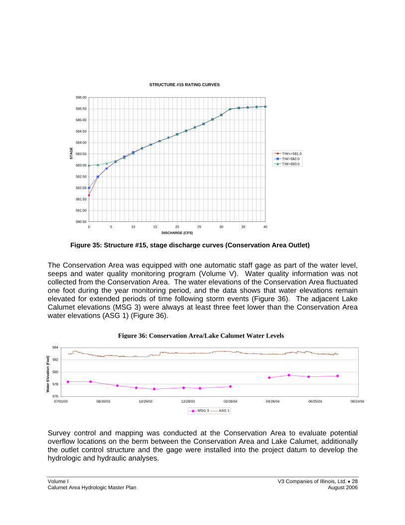
The Conservation Area was equipped with one automatic staff gage as part of the water level, seeps and water quality monitoring program (Volume V). Water quality information was not collected from the Conservation Area. The water elevations of the Conservation Area fluctuated one foot during the year monitoring period, and the data shows that water elevations remain elevated for extended periods of time following storm events (Figure 36). The adjacent Lake Calumet elevations (MSG 3) were always at least three feet lower than the Conservation Area water elevations (ASG 1) (Figure 36). Survey control and mapping was conducted at the Conservation Area to evaluate potential overflow locations on the berm between the Conservation Area and Lake Calumet, additionally the outlet control structure and the gage were installed into the project datum to develop the hydrologic and hydraulic analyses.
Conservation Area/Lake Calumet Water Levels
576
578
580
582
584
07/01/03 08/30/03 10/29/03 12/28/03 02/26/04 04/26/04 06/25/04 08/24/04
Wat
er E
leva
tion
(Fee
t)
MSG 3 ASG 1
Figure 33: Structure #15, facing North
Figure 36: Conservation Area/Lake Calumet Water Levels
STRUCTURE #15 RATING CURVES
580.50
581.00
581.50
582.00
582.50
583.00
583.50
584.00
584.50
585.00
585.50
586.00
0 5 10 15 20 25 30 35 40
DISCHARGE (CFS)
T/W<=581.0T/W=582.0T/W=583.0
STA
GE
Figure 35: Structure #15, stage discharge curves (Conservation Area Outlet)

Volume I V3 Companies of Illinois, Ltd. • 29 Calumet Area Hydrologic Master Plan August 2006
The overall HMP recommendations for the Conservation Area are summarized below:
o An annual structure maintenance program should be enacted for the outlet structure at the Conservation Area (Structure #15) (Volume IV).
o At Structure #15, V3 recommends stabilizing the outlet area of structure #15 with rip-rap and
constructing a secondary structure to convey flows from large storm events and reduce drawdown times of the Conservation Area waterbody (Volume IV).
Volume I V3 Companies of Illinois, Ltd. • 30 Calumet Area Hydrologic Master Plan August 2006
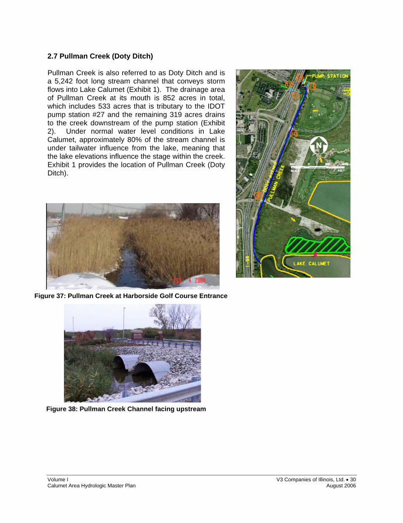
2.7 Pullman Creek (Doty Ditch) Pullman Creek is also referred to as Doty Ditch and is a 5,242 foot long stream channel that conveys storm flows into Lake Calumet (Exhibit 1). The drainage area of Pullman Creek at its mouth is 852 acres in total, which includes 533 acres that is tributary to the IDOT pump station #27 and the remaining 319 acres drains to the creek downstream of the pump station (Exhibit 2). Under normal water level conditions in Lake Calumet, approximately 80% of the stream channel is under tailwater influence from the lake, meaning that the lake elevations influence the stage within the creek. Exhibit 1 provides the location of Pullman Creek (Doty Ditch).
Figure 38: Pullman Creek Channel facing upstream
Figure 37: Pullman Creek at Harborside Golf Course Entrance

Volume I V3 Companies of Illinois, Ltd. • 31 Calumet Area Hydrologic Master Plan August 2006
Volume III provides the study in which V3 conducted a detailed Pump station analysis and evaluated the hydraulic capabilities of the Pullman Creek stream channel. The stream channel collects flows from a series of six culverts that drain sources such as the IDOT right of way and Harborside Golf Course. Hydraulic modeling indicated that the stream channel could not effectively convey floods for a 50 year storm event, which would result in pavement flooding. Additionally, sediment accumulation is a concern in the stream channels as it reduces the capacity to convey large flood flows. Pullman Creek was not included in the water level, seeps and water quality monitoring program. Lake Calumet water elevations for one year are provided in this volume which may assist with future planning efforts at Pullman Creek. Survey control and mapping was conducted at Pullman Creek to provide cross sections for the stream channel and to obtain elevations of the culverts and pump station located along Pullman Creek (Volume VI). Multiple recommendations are provided to improve the hydraulic functions of Pullman Creek. Recommendations include re-configuring the pump station, changing invert elevations of culverts, constructing an overpass bridge to remove culverts and dredging the Pullman Creek channel. The recommendations will improve reduce stage heights, and improve flood conveyance capacity and likely eliminate flooding issues associated with large storm events.
Volume I V3 Companies of Illinois, Ltd. • 32 Calumet Area Hydrologic Master Plan August 2006
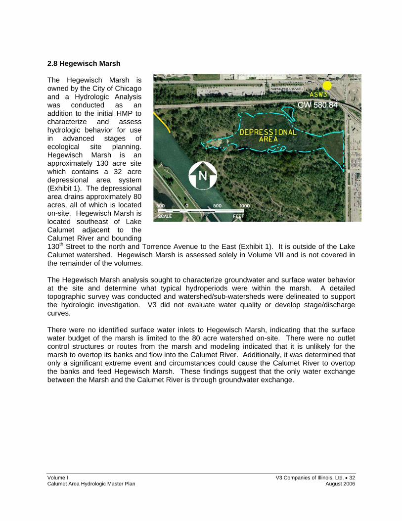
2.8 Hegewisch Marsh The Hegewisch Marsh is owned by the City of Chicago and a Hydrologic Analysis was conducted as an addition to the initial HMP to characterize and assess hydrologic behavior for use in advanced stages of ecological site planning. Hegewisch Marsh is an approximately 130 acre site which contains a 32 acre depressional area system (Exhibit 1). The depressional area drains approximately 80 acres, all of which is located on-site. Hegewisch Marsh is located southeast of Lake Calumet adjacent to the Calumet River and bounding 130th Street to the north and Torrence Avenue to the East (Exhibit 1). It is outside of the Lake Calumet watershed. Hegewisch Marsh is assessed solely in Volume VII and is not covered in the remainder of the volumes. The Hegewisch Marsh analysis sought to characterize groundwater and surface water behavior at the site and determine what typical hydroperiods were within the marsh. A detailed topographic survey was conducted and watershed/sub-watersheds were delineated to support the hydrologic investigation. V3 did not evaluate water quality or develop stage/discharge curves. There were no identified surface water inlets to Hegewisch Marsh, indicating that the surface water budget of the marsh is limited to the 80 acre watershed on-site. There were no outlet control structures or routes from the marsh and modeling indicated that it is unlikely for the marsh to overtop its banks and flow into the Calumet River. Additionally, it was determined that only a significant extreme event and circumstances could cause the Calumet River to overtop the banks and feed Hegewisch Marsh. These findings suggest that the only water exchange between the Marsh and the Calumet River is through groundwater exchange.

Volume I V3 Companies of Illinois, Ltd. • 33 Calumet Area Hydrologic Master Plan August 2006
Two automatic staff gages and a series of groundwater wells were installed and monitored for a one year period to investigate “actual” hydroperiods of the marsh system and a “perched” water body and characterize groundwater behavior. Additionally, this promoted an assessment of the relationship between groundwater and surface water. The results of this study conclude that groundwater is a significant influence on hydroperiods at Hegewisch Marsh. Surface water is also significant, which is driven by on-site precipitation runoff, evapotranspiration and infiltration. Extreme dry conditions plagued the monitoring period (October 2004-November 2005) of this study, which created at least one month of full drought. An HSPF Modeled hydroperiod during an average precipitation year indicates that drought periods in the marsh do occur, however, the duration of drought is significantly lower. These drought conditions are due to low precipitation conditions that lower the water table and cease surface water input to the site. Recommendations for Hegewisch Marsh hydrologic modifications as derived from Volume VII are provided below: (i) Obtain supplemental water from Calumet River through an on-site pump station (fixed or mobile).
The pump station would likely be utilized only during dry seasons when water elevations are low. The proximity of Calumet River provides an optimal source of water with reasonable water quality. However, this option would also require an outlet into the Calumet River, which could be a water control structure or a naturalized overflow channel. Additionally, this recommendation can assist in opening other funding opportunities, in the context of recycling Calumet River water and improving its water quality. The Sidestream Elevated Pool Aeration (SEPA) program is an example where funding is obtained to oxygenate the Calumet River waterways. Cycling Calumet River water through Hegewisch Marsh would establish an improvement in dissolved oxygen.
(ii) Construct a lined wall or grouted wall on the down-gradient (groundwater) side of the marsh
basin. This type of construction would have to sufficiently intersect the sand aquifer to back-up the groundwater flow and elevate groundwater elevations. This option would benefit from groundwater modeling to assist in design and benefit analysis.
(iii) Deepen or excavate significant pool areas in order to intersect the groundwater table year round.
This option would be more feasible in the south perched areas. For the marsh itself, this would require a basin bottom coring analysis to assess possible surface water elevation changes as a result of deepening the basin bottom elevations.
(iv) Obtain supplemental water by diverting storm water from adjacent areas. A feasibility study could
assess adjacent drainage basins that can be regarded/rerouted to supplement the hydrologic needs at Hegewisch Marsh. Taking into account the ecological objectives of this site, the water quality issues regarding the outside sources would also need to be addressed in this study. Additional funding opportunities may be available using this recommendation; providing stormwater is diverted into Hegewisch Marsh for pollution filtering that would otherwise feed directly into the Calumet River.
(v) Considering the monitoring record included in this report is during extreme drought conditions, V3
recommends continued monitoring of the staff gage in the marsh and the wells surrounding the. These are the most important locations for understanding the unique hydrologic processes at Hegewisch Marsh.
Volume I V3 Companies of Illinois, Ltd. • 34 Calumet Area Hydrologic Master Plan August 2006
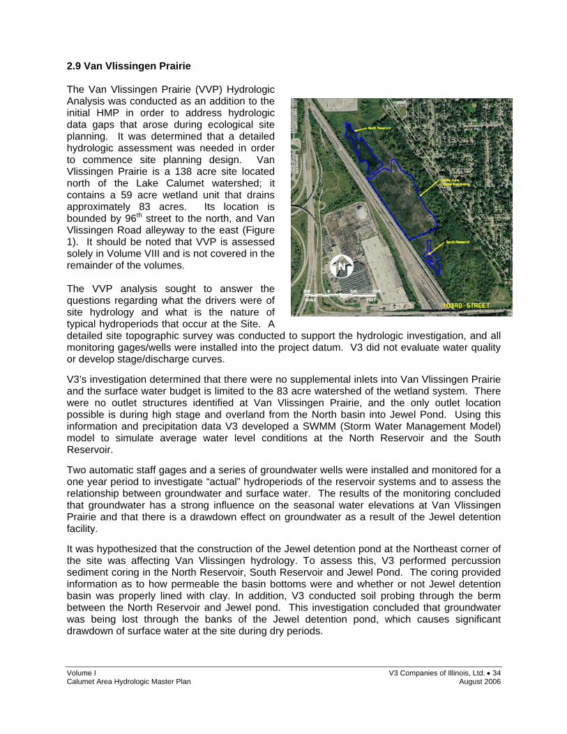
2.9 Van Vlissingen Prairie The Van Vlissingen Prairie (VVP) Hydrologic Analysis was conducted as an addition to the initial HMP in order to address hydrologic data gaps that arose during ecological site planning. It was determined that a detailed hydrologic assessment was needed in order to commence site planning design. Van Vlissingen Prairie is a 138 acre site located north of the Lake Calumet watershed; it contains a 59 acre wetland unit that drains approximately 83 acres. Its location is bounded by 96th street to the north, and Van Vlissingen Road alleyway to the east (Figure 1). It should be noted that VVP is assessed solely in Volume VIII and is not covered in the remainder of the volumes. The VVP analysis sought to answer the questions regarding what the drivers were of site hydrology and what is the nature of typical hydroperiods that occur at the Site. A detailed site topographic survey was conducted to support the hydrologic investigation, and all monitoring gages/wells were installed into the project datum. V3 did not evaluate water quality or develop stage/discharge curves. V3’s investigation determined that there were no supplemental inlets into Van Vlissingen Prairie and the surface water budget is limited to the 83 acre watershed of the wetland system. There were no outlet structures identified at Van Vlissingen Prairie, and the only outlet location possible is during high stage and overland from the North basin into Jewel Pond. Using this information and precipitation data V3 developed a SWMM (Storm Water Management Model) model to simulate average water level conditions at the North Reservoir and the South Reservoir. Two automatic staff gages and a series of groundwater wells were installed and monitored for a one year period to investigate “actual” hydroperiods of the reservoir systems and to assess the relationship between groundwater and surface water. The results of the monitoring concluded that groundwater has a strong influence on the seasonal water elevations at Van Vlissingen Prairie and that there is a drawdown effect on groundwater as a result of the Jewel detention facility. It was hypothesized that the construction of the Jewel detention pond at the Northeast corner of the site was affecting Van Vlissingen hydrology. To assess this, V3 performed percussion sediment coring in the North Reservoir, South Reservoir and Jewel Pond. The coring provided information as to how permeable the basin bottoms were and whether or not Jewel detention basin was properly lined with clay. In addition, V3 conducted soil probing through the berm between the North Reservoir and Jewel pond. This investigation concluded that groundwater was being lost through the banks of the Jewel detention pond, which causes significant drawdown of surface water at the site during dry periods.

Volume I V3 Companies of Illinois, Ltd. • 35 Calumet Area Hydrologic Master Plan August 2006
A series of recommendations are provided to enhance and optimize site hydrology based upon the ecological goals of the Van Vlissingen project, these recommendations are outlined below as found in Volume VIII.
(i) Excavate and deepen desired zones to optimal groundwater elevations. We provide a one year record of “extreme” drought conditions, this is valuable in that extreme lows are already known and excavation grades can be planned to optimize hydrologic conditions. Groundwater fluctuates a maximum of 3 feet around the marsh areas. This option would also benefit from the creation of an outlet control structure to further control the surface water elevations. This option will increase the connection between reservoir water and groundwater and will likely maintain hydrology on-site year round. Excavation activity should coordinate with environmental “hotspots” that need to be excavated. This option should also incorporate option 2.
(ii) Re-claim former groundwater levels in the northern portion of the Site. This may be accomplished by re-lining the southwest and west slopes of the Jewel Pond with a very thick and low hydraulic conductivity soil, geo-synthetic clay liner or grouting. It is believed that groundwater levels around the North Reservoir will be increased, but never to the pre-Jewel Pond water table elevations. This solution will decrease groundwater drawdown on-site and increase the duration of hydroperiods in and around the North Reservoir. This solution will assist in maintaining water levels in the North Reservoir during drought periods.
(iii) Increase drainage area (increase surface water entering the Site). This would increase the amount of water entering the reservoirs. The supplemental water would provide increased inundation and storage, and decrease the duration of drying periods on-site. Options include:
o Collect stormwater runoff that currently drains to the east, accomplished by constructing a water quality basin that stores the stormwater and makes it available for pumping back to the western portions of the Site. Water quality would have to be assessed, but this source of runoff would likely be of better quality than storm water diverted from impervious sources.
o Divert stormwater from off-site. This would require an additional feasibility study to assess sources and water quality.
(iv) Site planning option: Reduce evaporative potential when developing restoration plans for the Site.
Field observations indicate the reservoirs are susceptible to notable wind fetch. Wind drastically increases evaporation, and any additional wetland enhancement or creation should consider reducing this effect by developing corridor type reservoirs rather than open water.
(v) Consider the addition of organic or mineral soil as substrate in the Central Zone and South Reservoir. Currently these perched zones on the Site are bottomed with cemented slag and concrete, materials that store heat collected during the day which increases evaporation and increases water temperature (this has biotic influences as well).
Volume I V3 Companies of Illinois, Ltd. • 36 Calumet Area Hydrologic Master Plan August 2006
3. SUMMARY The Calumet Area EMA sites are each unique and are influenced by a diverse range of hydrologic and hydraulic factors. Collectively, the proceeding volumes of the Calumet Area Hydrologic Master Plan provide an essential tool that characterizes and interprets water behavior in the Calumet Area. We trust that this series of volumes will provide significant value for all the future ecological rehabilitation and enhancement efforts.

Volume I V3 Companies of Illinois, Ltd. • 37 Calumet Area Hydrologic Master Plan August 2006
GLOSSARY
Automatic Staff Gage (ASG) : Apparatus installed to collect sufrace water elevations of water bodies at 15 minute intervals. Anoxic : Water that contains little to no dissolved oxygen. Conveyance Capacity : The maximum amount of water that can be transported downstream by a pipe or channel. Discharge : The rate of water flowing out of a site. Dredging : Process of removing sediment accumulation from lake and river bottoms. Equality Formation : Tongues of glacial lake deposits that consist of silts, clays and sands. Evapotranspiration : Proportion of waterbudget that is returned to the air through evaporation and transpiration (plant uptake). Glacio-fluvial : Sediment or lithified sequence deposited from meltwater streams flowing from or within glaciers. Glacio-lacustrine : Sediment or lithified sequence deposited within a glacial lake. Gradient : Slope of a surface, generally pertaining to groundwater surfaces in these texts. Headwater : The depth of water at the upstream end of a control structure or pipe. HEC-RAS : Hydraulic Engineering Center – River Analysis System. A computation program widely used for developing water surface profiles for streams and ditches. Hummock : Micro-topographic mounds that usually form from soil consolidation and poor surface water drainage. Hydraulics : The determination of water surface elevations through relationships of flow and physical geography. Hydrology : The determination of stormwater runoff rates and volumes for a study area based on rainfall data and physical geography. Hydroperiod : A simulated or measured time duration of water elevations. Infiltration : The downward movement of water through pores or small openings in soil or rock. Inudation : Standing surface water. Manual Staff Gage (MSG) : Apparatus installed within surface water body to visually observe surface water elevations (observations conducted once per month).

Volume I V3 Companies of Illinois, Ltd. • 38 Calumet Area Hydrologic Master Plan August 2006
Mottles : Soil discolorations usually caused by chemical interactions between water and chemicals/minerals within the soil. Orifice : A control structure ; a small opening, usually in a metal plate or wall, used to restrict the amount of water discharging from a site. Permeability : The capacity of rock or sediment for transmitting fluid flow under unequal pressure. Piezometer : A well installed into the ground that penetrates an underground water bearing unit – in which the groundwater elevation can be monitored along with its associated head. Reduction : The removal of oxygen from soil or water. Slag : Iron and steel manufacturing by-product. Waste material resulting from the impurities of mineral ore and ash from coke. Stage-Discharge Rating Curve : A curve illustrating discharge rates for water leaving a site at given stages or elevations. Seep : A location where groundwater discharges to the surface. Stop Logs : Removable planks used to block water from leaving a site. The top stop log will set the normal pool level for a basin. Stormwater Control Structure : A device, usually an orifice or a weir, used to regulate water discharge from a site. Stratigraphy : The arrangement of rock and or soil types in chronologic order of sequence. Submerged : Located entirely underwater. Tailwater : The depth of water at the downstream end of a control structure or pipe. Watershed : The area the drains to a similar point location or water body. Weir : A control structure that prevents discharge from a site until the headwater exceeds the overflow elevation. * All words not necessarily referred to in text

EEEXXXHHHIIIBBBIIITTT III:::
AERIAL VIEW OF CALUMET AREA EMA LOCATIONS

Cal
umet
Riv
er
103rd Street
130th Street
122nd Street
Torr
ence
Ave
nue
I-94Bishop
Ford
Dea
dstic
k Po
nd
Lake Calumet
Conservation Area
HeronPond
Big Marsh
Hegewisch Marsh
Van Vlissingen Prairie
Indian RidgeMarsh North
IndianRidge Marsh South
Pullm
an C
reek
/Dot
y Di
tch
T IT LE :
P R O JE C T A N D S IT E L O C A T IO N :
B A S E LA Y E R :
P R O JE C T N O .
F IG U R E :
S H E E T: O F:
C LIE N T:
Q U A D R A N G LE :
D A T E :
S C A LE :
Aerial View of Calumet Area EMA Locations
2004 Aerial
Chicago Department of Environment30 North LaSalle Street, Suite 2500
Chicago, Illinois 60602
Calumet Area Hydrologic Master Plan (HMP)
98216HMP
Chicago/Calumet
1
September 2005
11
scale bar
V3 Companies120 N. LaSalle St, Suite 1550Chicago, IL 60602312.419.1985 phone312.419.1986 faxwww.v3co.com
0.5 0 0.5 10.25Miles
±
EEEXXXHHHIIIBBBIIITTT IIIIII:::
A & B: CALUMET AREA WATERSHED ATLASES

...\Mstn\E202A\1-coversht-R.dgn 9/8/2006 1:47:21 PM

...\Mstn\E202A\2-aerial.dgn 9/8/2006 1:51:14 PM

EEEXXXHHHIIIBBBIIITTT IIIIIIIII:::
HMP MONITORING LOCATIONS MAP

...\FIGhydroconcep04-21-05VVP.dgn 9/8/2006 12:09:04 PM