cambridge international examinations cambridge ordinary level … levels/physics...
TRANSCRIPT
This document consists of 8 printed pages.
DC (LEG/CGW) 120199/4© UCLES 2016 [Turn over
Cambridge International ExaminationsCambridge Ordinary Level
*1025743965*
PHYSICS 5054/42Paper 4 Alternative to Practical October/November 2016 1 hourCandidates answer on the Question Paper.No Additional Materials are required.
READ THESE INSTRUCTIONS FIRST
Write your Centre number, candidate number and name on all the work you hand in.Write in dark blue or black pen.You may use an HB pencil for any diagrams or graphs.Do not use staples, paper clips, glue or correction fluid.DO NOT WRITE IN ANY BARCODES.
Answer all questions.
Electronic calculators may be used.You may lose marks if you do not show your working or if you do not use appropriate units.
At the end of the examination, fasten all your work securely together.The number of marks is given in brackets [ ] at the end of each question or part question.
2
5054/42/O/N/16© UCLES 2016
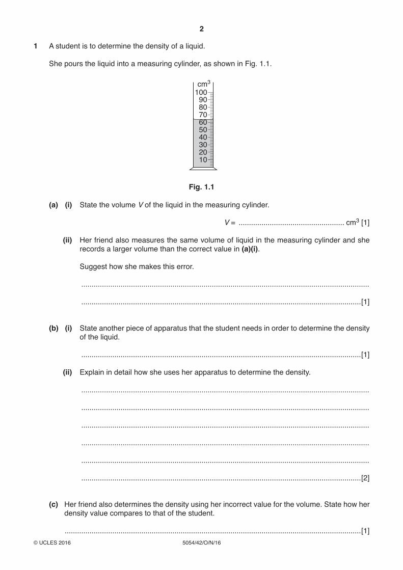
1 A student is to determine the density of a liquid.
She pours the liquid into a measuring cylinder, as shown in Fig. 1.1.
100cm3
908070605040302010
Fig. 1.1
(a) (i) State the volume V of the liquid in the measuring cylinder.
V = ................................................... cm3 [1]
(ii) Her friend also measures the same volume of liquid in the measuring cylinder and she records a larger volume than the correct value in (a)(i).
Suggest how she makes this error.
...........................................................................................................................................
.......................................................................................................................................[1]
(b) (i) State another piece of apparatus that the student needs in order to determine the density of the liquid.
.......................................................................................................................................[1]
(ii) Explain in detail how she uses her apparatus to determine the density.
...........................................................................................................................................
...........................................................................................................................................
...........................................................................................................................................
...........................................................................................................................................
...........................................................................................................................................
.......................................................................................................................................[2]
(c) Her friend also determines the density using her incorrect value for the volume. State how her density value compares to that of the student.
...............................................................................................................................................[1]
3
5054/42/O/N/16© UCLES 2016 [Turn over
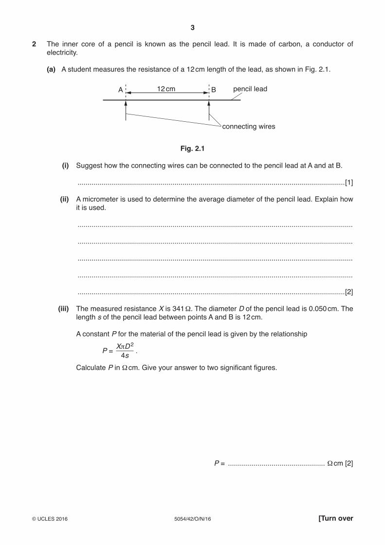
2 The inner core of a pencil is known as the pencil lead. It is made of carbon, a conductor of electricity.
(a) A student measures the resistance of a 12 cm length of the lead, as shown in Fig. 2.1.
12 cm pencil lead
connecting wires
BA
Fig. 2.1
(i) Suggest how the connecting wires can be connected to the pencil lead at A and at B.
.......................................................................................................................................[1]
(ii) A micrometer is used to determine the average diameter of the pencil lead. Explain how it is used.
...........................................................................................................................................
...........................................................................................................................................
...........................................................................................................................................
...........................................................................................................................................
.......................................................................................................................................[2]
(iii) The measured resistance X is 341 Ω. The diameter D of the pencil lead is 0.050 cm. The length s of the pencil lead between points A and B is 12 cm.
A constant P for the material of the pencil lead is given by the relationship
P = XπD 24s .
Calculate P in Ω cm. Give your answer to two significant figures.
P = ................................................. Ω cm [2]
4
5054/42/O/N/16© UCLES 2016
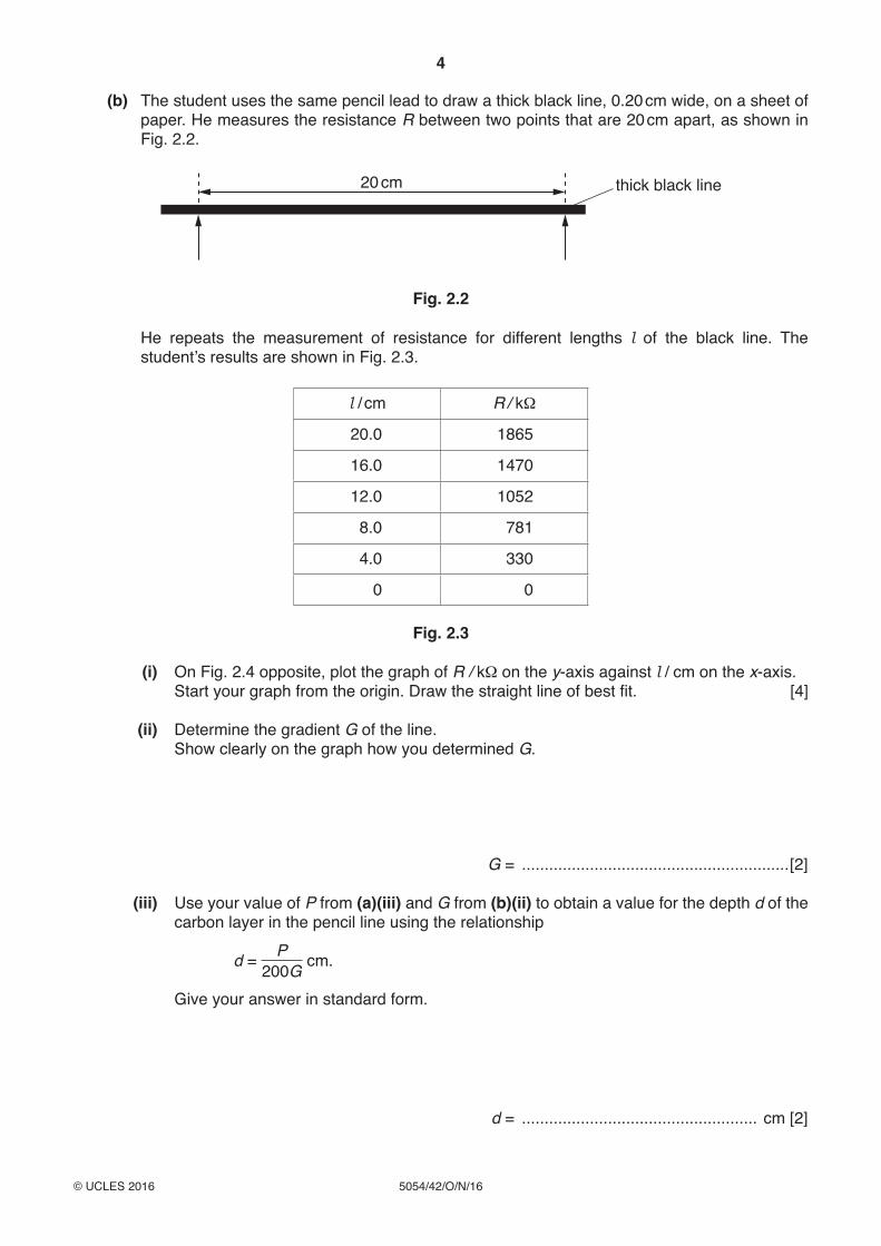
(b) The student uses the same pencil lead to draw a thick black line, 0.20 cm wide, on a sheet of paper. He measures the resistance R between two points that are 20 cm apart, as shown in Fig. 2.2.
20 cm thick black line
Fig. 2.2
He repeats the measurement of resistance for different lengths l of the black line. The student’s results are shown in Fig. 2.3.
l / cm R / kΩ
20.0 1865
16.0 1470
12.0 1052
8.0 781
4.0 330
0 0
Fig. 2.3
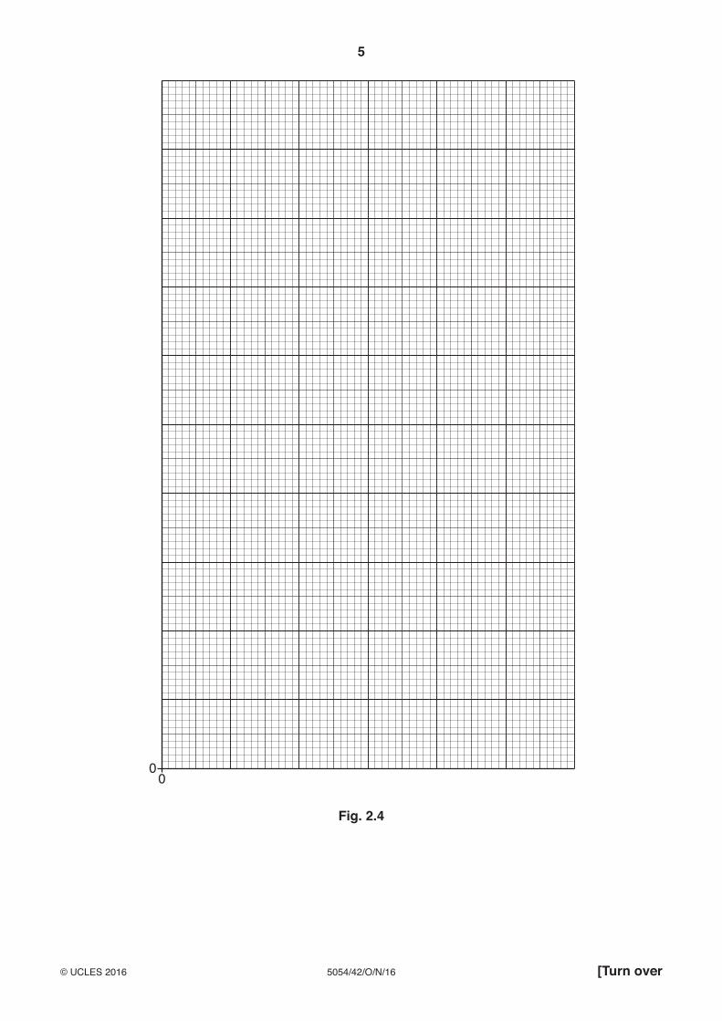
(i) On Fig. 2.4 opposite, plot the graph of R / kΩ on the y-axis against l / cm on the x-axis. Start your graph from the origin. Draw the straight line of best fit. [4]
(ii) Determine the gradient G of the line. Show clearly on the graph how you determined G.
G = ...........................................................[2]
(iii) Use your value of P from (a)(iii) and G from (b)(ii) to obtain a value for the depth d of the carbon layer in the pencil line using the relationship
d = P200G cm.
Give your answer in standard form.
d = .................................................... cm [2]
5
5054/42/O/N/16© UCLES 2016 [Turn over
00
Fig. 2.4
6
5054/42/O/N/16© UCLES 2016
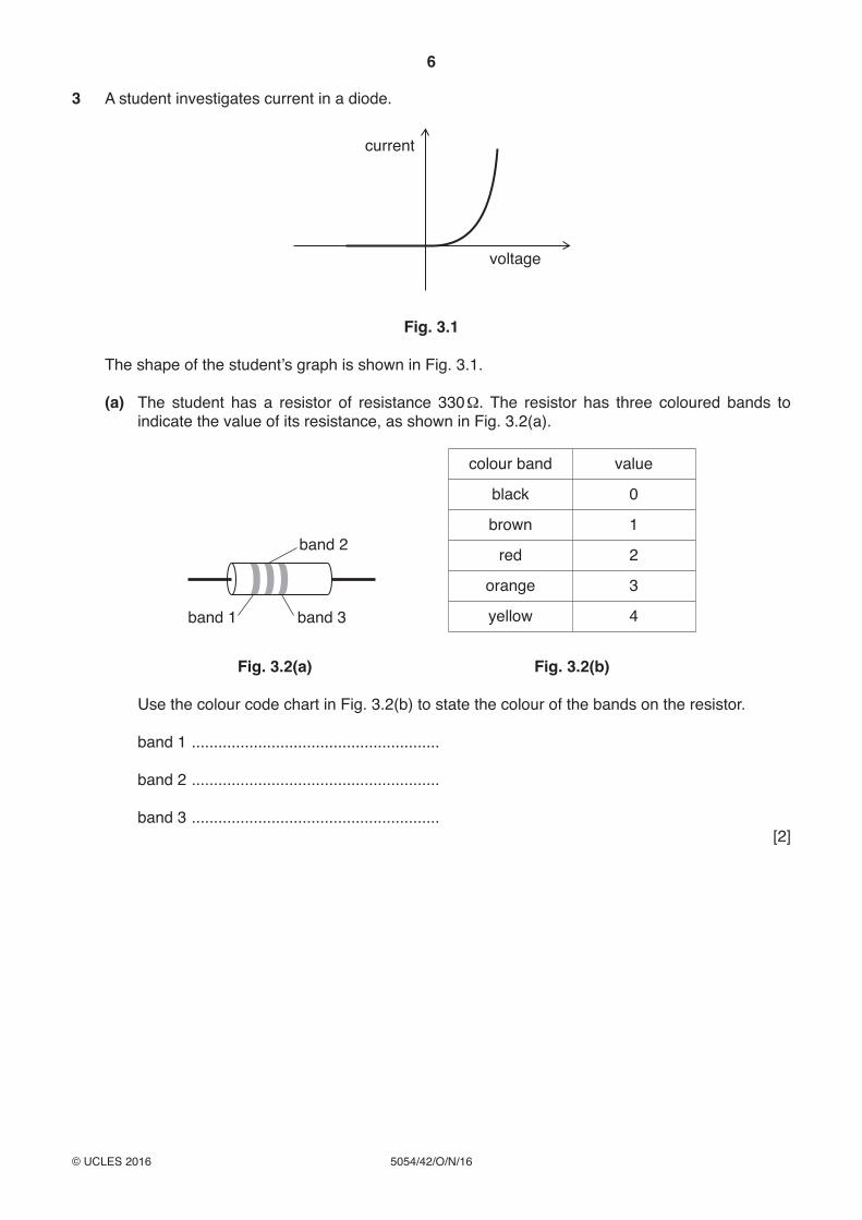
3 A student investigates current in a diode.
voltage
current
Fig. 3.1
The shape of the student’s graph is shown in Fig. 3.1.
(a) The student has a resistor of resistance 330 Ω. The resistor has three coloured bands to indicate the value of its resistance, as shown in Fig. 3.2(a).
band 2
band 3band 1
colour band value
black 0
brown 1
red 2
orange 3
yellow 4
Fig. 3.2(a) Fig. 3.2(b)
Use the colour code chart in Fig. 3.2(b) to state the colour of the bands on the resistor.
band 1 ........................................................
band 2 ........................................................
band 3 ........................................................ [2]
7
5054/42/O/N/16© UCLES 2016 [Turn over
(b) The student uses the resistor in series with the diode to protect the diode.
He sets up a circuit to measure different values of the current in the diode and the voltage across the diode.
In the space below, draw the circuit diagram the student can use.
[3]
(c) Explain how the student can take readings for different values of V.
...................................................................................................................................................
...............................................................................................................................................[1]
(d) The diode conducts current in one direction and does not conduct in the other direction. State how the circuit can be changed to show this.
...................................................................................................................................................
...............................................................................................................................................[1]
Please turn over for Question 4.
Permission to reproduce items where third-party owned material protected by copyright is included has been sought and cleared where possible. Every reasonable effort has been made by the publisher (UCLES) to trace copyright holders, but if any items requiring clearance have unwittingly been included, the publisher will be pleased to make amends at the earliest possible opportunity.
To avoid the issue of disclosure of answer-related information to candidates, all copyright acknowledgements are reproduced online in the Cambridge International Examinations Copyright Acknowledgements Booklet. This is produced for each series of examinations and is freely available to download at www.cie.org.uk after the live examination series.
Cambridge International Examinations is part of the Cambridge Assessment Group. Cambridge Assessment is the brand name of University of Cambridge Local Examinations Syndicate (UCLES), which is itself a department of the University of Cambridge.
8
5054/42/O/N/16© UCLES 2016
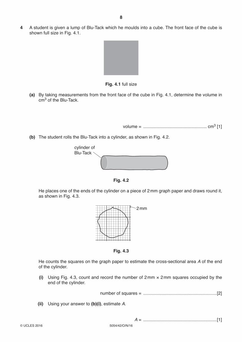
4 A student is given a lump of Blu-Tack which he moulds into a cube. The front face of the cube is shown full size in Fig. 4.1.
Fig. 4.1 full size
(a) By taking measurements from the front face of the cube in Fig. 4.1, determine the volume in cm3 of the Blu-Tack.
volume = ................................................... cm3 [1]
(b) The student rolls the Blu-Tack into a cylinder, as shown in Fig. 4.2.
cylinder ofBlu-Tack
Fig. 4.2
He places one of the ends of the cylinder on a piece of 2 mm graph paper and draws round it, as shown in Fig. 4.3.
2 mm
Fig. 4.3
He counts the squares on the graph paper to estimate the cross-sectional area A of the end of the cylinder.
(i) Using Fig. 4.3, count and record the number of 2 mm × 2 mm squares occupied by the end of the cylinder.
number of squares = ...........................................................[2]
(ii) Using your answer to (b)(i), estimate A.
A = ...........................................................[1]