camless variable valve actuator with two discrete lifts · camless variable valve actuation (vva)...
TRANSCRIPT
AbstractCamless Variable Valve Actuation (VVA) technologies have been known for improving fuel economy, reducing emissions, and enhancing engine performance. VVA can be divided into electro-magnetic, electro-hydraulic, and electro-pneumatic actuation. This paper presents an electro-hydraulic VVA design (called GD-VVA-2) that offers continuously variable timing and two discrete lifts (low lift S1 and high lift S2). The lift control is achieved through a lift control sleeve, which is hydraulically switched between two mechanically defined positions to provide accurate lifts. The low lift S1 has a wide design range, anywhere between zero and the high lift S2, i.e., 0 < S1 < S2. If S1 ≥ 0.5*S2, engine valves may operate at the low lift during most of a typical drive cycle. Operation at the low lift reduces energy consumption significantly. The GD-VVA-2 design offers compact package size and reasonable energy consumption. One of the prototype samples has passed 400 hours of 6000-rpm durability test on a test bench.
IntroductionEngines with Variable Valve Actuation (VVA) systems are capable of continuously variable lift and timing at any given operational condition to minimize the engine pumping loss with optimized combustion to improve engine performances in fuel economy, emissions, and torque delivery [1, 2, 3, 21].
Engine valvetrain systems can be generally grouped into cam-based and camless. A cam-based valvetrain system is based upon the traditional cam-system to drive the engine intake and exhaust valves with limited control over valve timing and/or lift, and it is now widely adopted in many new engines. A camless system drives individual engine valve directly with electromagnetic [4, 5, 6, 7], electro-pneumatic [8, 9], or electrohydraulic [10, 11, 12] VVA system. Without the restriction of the cam system, a camless system
is able to adjust both valve lift and timing to achieve any desired target levels that can be varied cycle-by-cycle. In addition, it provides independent control of engine valves with different opening and lift patterns for each cylinder. For example, it is able to provide asymmetric opening for two intake valves for a single cylinder, resulting in better charge air and fuel mixing. It can also selectively deactivate one or more cylinders under low load conditions. Camless systems thus offer more control freedom and greater performance benefits than conventional cam-based valve systems.
Camless systems are a key technical enabler for other advanced engine technologies, such as air hybrid vehicles [13], Homogenous Charge Compression Ignition (HCCI) [14], and high efficient diesel engines [15].
One trend in cam-based VVA systems is to adopt cost effective two-step lift or two-lift designs [16, 17]. While a camless VVA design may satisfy most of the engine operation needs even with one lift [18], a second discrete lift of a substantial height adds more control flexibility and benefits. These benefits include more effective throttle-less operation, VVA system power consumption reduction by low-lift operation at low engine speed with low load, and re-breathing capability for advanced combustion modes.
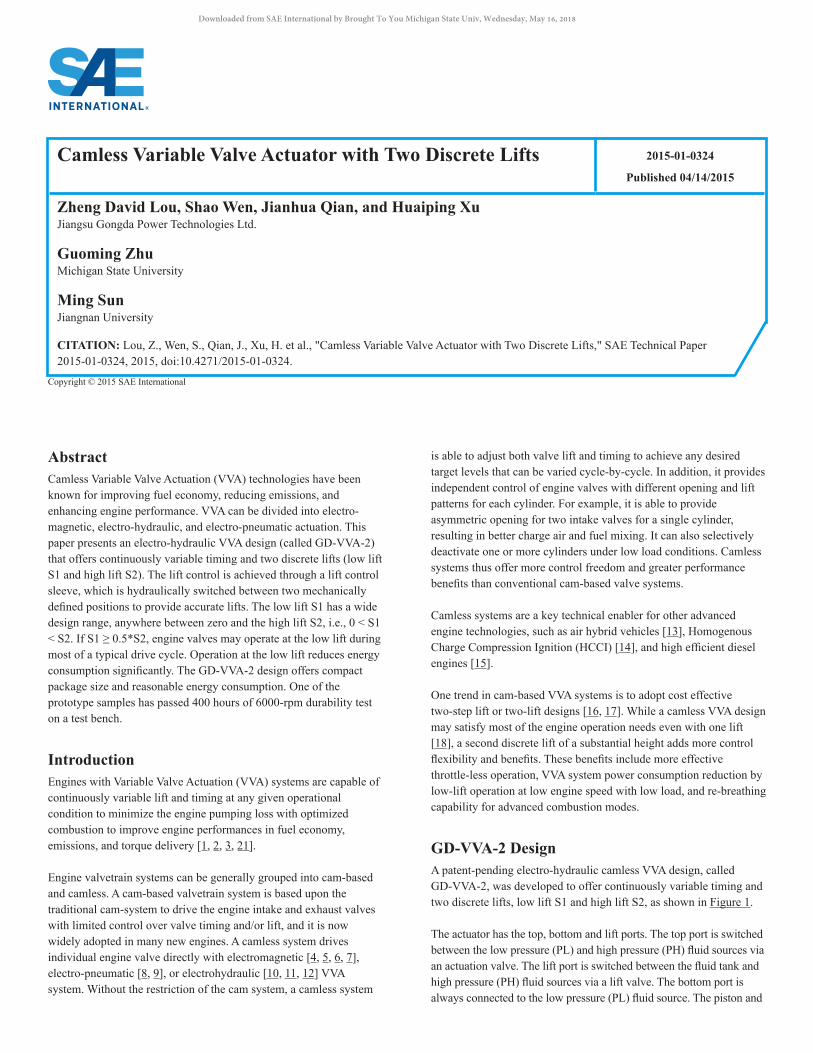
GD-VVA-2 DesignA patent-pending electro-hydraulic camless VVA design, called GD-VVA-2, was developed to offer continuously variable timing and two discrete lifts, low lift S1 and high lift S2, as shown in Figure 1.
The actuator has the top, bottom and lift ports. The top port is switched between the low pressure (PL) and high pressure (PH) fluid sources via an actuation valve. The lift port is switched between the fluid tank and high pressure (PH) fluid sources via a lift valve. The bottom port is always connected to the low pressure (PL) fluid source. The piston and
Camless Variable Valve Actuator with Two Discrete Lifts 2015-01-0324
Published 04/14/2015
Zheng David Lou, Shao Wen, Jianhua Qian, and Huaiping XuJiangsu Gongda Power Technologies Ltd.
Guoming ZhuMichigan State University
Ming SunJiangnan University
CITATION: Lou, Z., Wen, S., Qian, J., Xu, H. et al., "Camless Variable Valve Actuator with Two Discrete Lifts," SAE Technical Paper 2015-01-0324, 2015, doi:10.4271/2015-01-0324.
Copyright © 2015 SAE International
Downloaded from SAE International by Brought To You Michigan State Univ, Wednesday, May 16, 2018
the engine are thus pushed downward when the top port is pressurized and returned upward by the return spring when the top port is at its default low pressure state shown in Figure 1.
The axial position of the lift control sleeve is determined by the fluid force balance on its two end surfaces. In the default position shown in Figure 1, the low pressure (PL) on the top of the lift control is able to exert sufficient force to keep the lift control sleeve in its lower position, and thus the actuator operates at the high lift S2. This is because the low pressure (PL) is higher than the tank pressure that is close to the atmosphere pressure. The lift control sleeve moves up, and thus the actuator operates at the low lift S1 when the lift port is pressurized. The lift control sleeve is sized large enough for its end surface area so that it does drift even when it is being hit by an opening piston.
One actuation valve may be shared by a pair of intake or exhaust engine valves on the same engine cylinder if the two engine valves operate with the synchronized motion. One lift valve may be shared by all engine valves unless one seeks lift differentiation.
Figure 1. A Schematic of GD-VVA-2 Design
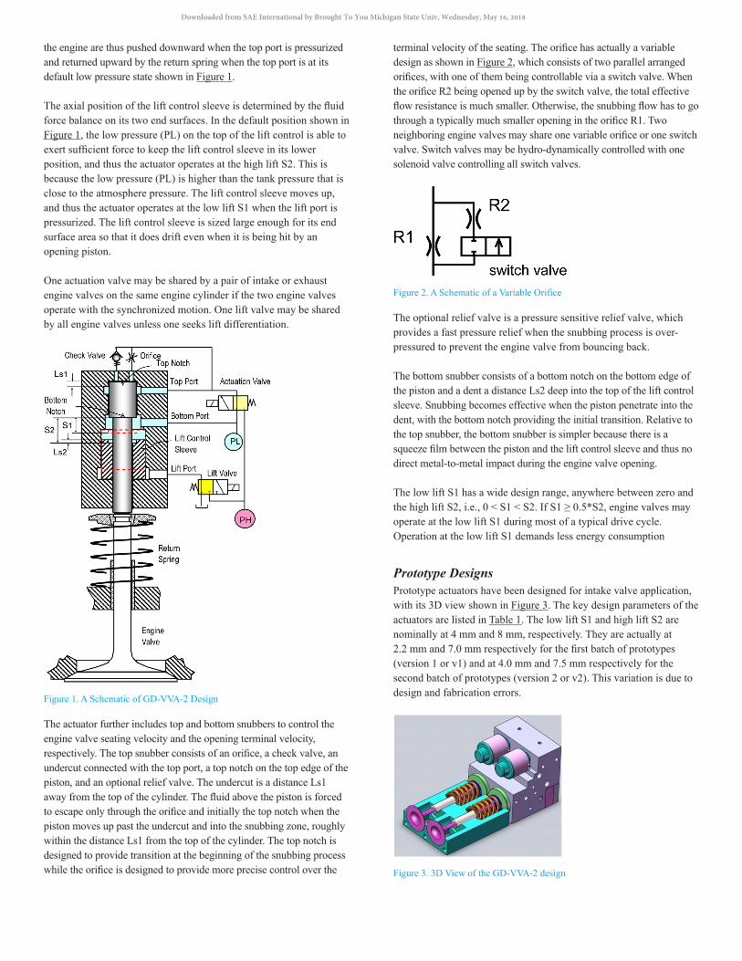
The actuator further includes top and bottom snubbers to control the engine valve seating velocity and the opening terminal velocity, respectively. The top snubber consists of an orifice, a check valve, an undercut connected with the top port, a top notch on the top edge of the piston, and an optional relief valve. The undercut is a distance Ls1 away from the top of the cylinder. The fluid above the piston is forced to escape only through the orifice and initially the top notch when the piston moves up past the undercut and into the snubbing zone, roughly within the distance Ls1 from the top of the cylinder. The top notch is designed to provide transition at the beginning of the snubbing process while the orifice is designed to provide more precise control over the
terminal velocity of the seating. The orifice has actually a variable design as shown in Figure 2, which consists of two parallel arranged orifices, with one of them being controllable via a switch valve. When the orifice R2 being opened up by the switch valve, the total effective flow resistance is much smaller. Otherwise, the snubbing flow has to go through a typically much smaller opening in the orifice R1. Two neighboring engine valves may share one variable orifice or one switch valve. Switch valves may be hydro-dynamically controlled with one solenoid valve controlling all switch valves.
Figure 2. A Schematic of a Variable Orifice
The optional relief valve is a pressure sensitive relief valve, which provides a fast pressure relief when the snubbing process is over-pressured to prevent the engine valve from bouncing back.
The bottom snubber consists of a bottom notch on the bottom edge of the piston and a dent a distance Ls2 deep into the top of the lift control sleeve. Snubbing becomes effective when the piston penetrate into the dent, with the bottom notch providing the initial transition. Relative to the top snubber, the bottom snubber is simpler because there is a squeeze film between the piston and the lift control sleeve and thus no direct metal-to-metal impact during the engine valve opening.
The low lift S1 has a wide design range, anywhere between zero and the high lift S2, i.e., 0 < S1 < S2. If S1 ≥ 0.5*S2, engine valves may operate at the low lift S1 during most of a typical drive cycle. Operation at the low lift S1 demands less energy consumption
Prototype DesignsPrototype actuators have been designed for intake valve application, with its 3D view shown in Figure 3. The key design parameters of the actuators are listed in Table 1. The low lift S1 and high lift S2 are nominally at 4 mm and 8 mm, respectively. They are actually at 2.2 mm and 7.0 mm respectively for the first batch of prototypes (version 1 or v1) and at 4.0 mm and 7.5 mm respectively for the second batch of prototypes (version 2 or v2). This variation is due to design and fabrication errors.
Figure 3. 3D View of the GD-VVA-2 design
Downloaded from SAE International by Brought To You Michigan State Univ, Wednesday, May 16, 2018
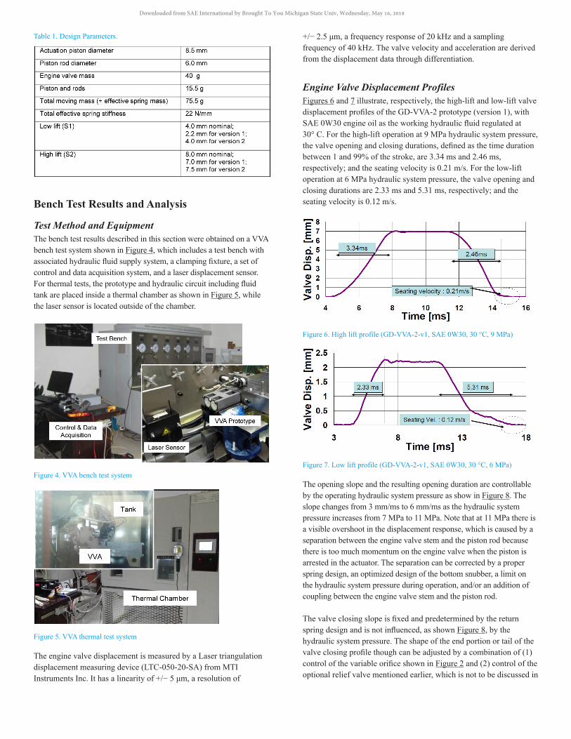
Table 1. Design Parameters.
Bench Test Results and Analysis
Test Method and EquipmentThe bench test results described in this section were obtained on a VVA bench test system shown in Figure 4, which includes a test bench with associated hydraulic fluid supply system, a clamping fixture, a set of control and data acquisition system, and a laser displacement sensor. For thermal tests, the prototype and hydraulic circuit including fluid tank are placed inside a thermal chamber as shown in Figure 5, while the laser sensor is located outside of the chamber.
Figure 4. VVA bench test system
Figure 5. VVA thermal test system
The engine valve displacement is measured by a Laser triangulation displacement measuring device (LTC-050-20-SA) from MTI Instruments Inc. It has a linearity of +/− 5 μm, a resolution of
+/− 2.5 μm, a frequency response of 20 kHz and a sampling frequency of 40 kHz. The valve velocity and acceleration are derived from the displacement data through differentiation.
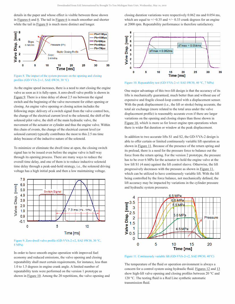
Engine Valve Displacement ProfilesFigures 6 and 7 illustrate, respectively, the high-lift and low-lift valve displacement profiles of the GD-VVA-2 prototype (version 1), with SAE 0W30 engine oil as the working hydraulic fluid regulated at 30° C. For the high-lift operation at 9 MPa hydraulic system pressure, the valve opening and closing durations, defined as the time duration between 1 and 99% of the stroke, are 3.34 ms and 2.46 ms, respectively; and the seating velocity is 0.21 m/s. For the low-lift operation at 6 MPa hydraulic system pressure, the valve opening and closing durations are 2.33 ms and 5.31 ms, respectively; and the seating velocity is 0.12 m/s.
Figure 6. High lift profile (GD-VVA-2-v1, SAE 0W30, 30 °C, 9 MPa)
Figure 7. Low lift profile (GD-VVA-2-v1, SAE 0W30, 30 °C, 6 MPa)
The opening slope and the resulting opening duration are controllable by the operating hydraulic system pressure as show in Figure 8. The slope changes from 3 mm/ms to 6 mm/ms as the hydraulic system pressure increases from 7 MPa to 11 MPa. Note that at 11 MPa there is a visible overshoot in the displacement response, which is caused by a separation between the engine valve stem and the piston rod because there is too much momentum on the engine valve when the piston is arrested in the actuator. The separation can be corrected by a proper spring design, an optimized design of the bottom snubber, a limit on the hydraulic system pressure during operation, and/or an addition of coupling between the engine valve stem and the piston rod.
The valve closing slope is fixed and predetermined by the return spring design and is not influenced, as shown Figure 8, by the hydraulic system pressure. The shape of the end portion or tail of the valve closing profile though can be adjusted by a combination of (1) control of the variable orifice shown in Figure 2 and (2) control of the optional relief valve mentioned earlier, which is not to be discussed in
Downloaded from SAE International by Brought To You Michigan State Univ, Wednesday, May 16, 2018
details in the paper and whose effect is visible between those shown in Figures 6 and 8. The tail in Figure 6 is much smoother and shorter while the tail in Figure 8 is much more distinct and longer.
Figure 8. The impact of the system pressure on the opening and closing profiles (GD-VVA-2-v1, SAE 0W30, 30 °C)
As the engine speed increases, there is a need to start closing the engine valve as soon as it is fully-open. A zero-dwell valve profile is shown in Figure 9. There is a time delay of about 2.5 ms between the signal switch and the beginning of the valve movement for either opening or closing. An engine valve opening or closing action includes the following steps: delivery of a switch signal from the valve control box, the change of the electrical current level to the solenoid, the shift of the solenoid pilot valve, the shift of the main hydraulic valve, the movement of the actuator or cylinder and thus the engine valve. Within this chain of events, the change of the electrical current level (or solenoid current) typically contributes the most to this 2.5 ms time delay because of the inductive nature of the solenoid.
To minimize or eliminate the dwell time at open, the closing switch signal has to be issued even before the engine valve is half-way through its opening process. There are many ways to reduce the overall time delay, and one of them is to reduce inductive solenoid time delay through a peak-and-hold strategy, i.e., the solenoid driving voltage has a high initial peak and then a low maintaining voltage.
Figure 9. Zero-dwell valve profile (GD-VVA-2-v2, SAE 0W30, 30 °C, 8 MPa)
In order to have smooth engine operation with improved fuel economy and reduced emissions, the valve opening and closing repeatability shall meet certain requirements, for instance, less than 1.0 to 1.5 degrees in engine crank angle. A limited number of repeatability tests were performed on the version 1 prototype as shown in Figure 10. Among the 20 repetitions, the valve opening and
closing duration variations were respectively 0.062 ms and 0.054 ms, which are equal to +/−0.35 and +/− 0.33 crank degrees for an engine at 2000 rpm. Repeatability performance is therefore satisfactory.
Figure 10. Repeatability test (GD-VVA-2-v1 SAE 0W30, 40 °C, 7 MPa)
One major advantage of this two-lift design is that the accuracy of its lifts is mechanically guaranteed, much better than and without use of expensive and fragile closed-loop control with a displacement sensor. With the peak displacement (i.e., the lift or stroke) being accurate, the total air exchange (more related to the total area under the valve displacement profile) is reasonably accurate even if there are larger variations on the opening and closing slopes than those shown in Figure 10, which is more so for lower engine rpm operations when there is wider flat duration or window at the peak displacement.
In addition to two accurate lifts S1 and S2, the GD-VVA-2 design is able to offer certain or limited continuously variable lift operation as shown in Figure 11. Because of the presence of the return spring and its preload, there is a need for the pressure force to balance out the force from the return spring. For the version 2 prototype, the pressure has to be over 6 MPa for the actuator to hold the engine valve at the low lift S1 (4 mm) against the lift control sleeve. Otherwise, the lift progressively decreases with the pressure as shown in Figure 11, which can be utilized to have continuously variable lift. With the lift being controlled by the force balance, not mechanically defined, the lift accuracy may be impacted by variations in the cylinder pressure and hydraulic system pressures.
Figure 11. Continuously variable lift (GD-VVA-2-v2, SAE 0W30, 40°C)
The temperature of the fluid or operation environment is always a concern for a control system using hydraulic fluid. Figures 12 and 13 show high-lift valve opening and closing profiles between 20 °C and 120 °C. The testing fluid is a Red Line synthetic automatic transmission fluid.
Downloaded from SAE International by Brought To You Michigan State Univ, Wednesday, May 16, 2018
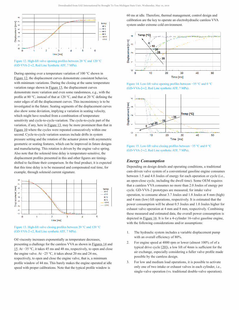
Figure 12. High-lift valve opening profiles between 20 °C and 120 °C (GD-VVA-2-v2, Red Line Synthetic ATF, 7 MPa).
During opening over a temperature variation of 100 °C shown in Figure 12, the displacement curves demonstrate consistent behavior, with minimum variations. During the closing at the same temperature variation range shown in Figure 13, the displacement curves demonstrate more variation and even some randomness, e.g., with the profile at 80 °C, instead of that at 120 °C, and that at 20 °C defining the outer edges of all the displacement curves. This inconsistency is to be investigated in the future. Seating segments of the displacement curves also show some deviation, implying a variation in seating velocity, which might have resulted from a combination of temperature sensitivity and cycle-to-cycle-variation. The cycle-to-cycle part of the variation, if any, here in Figure 13, may be more prominent than that in Figure 10 where the cycles were repeated consecutively within one second. Cycle-to-cycle variation sources include drifts in system pressure setting and the rotation of the actuator piston with asymmetric geometric or seating features, which can be improved in future designs and manufacturing. This rotation is driven by the engine valve spring. Also note that the solenoid time delay is temperature-sensitive, the displacement profiles presented in this and other figures are timing-shifted to facilitate their comparison. In the final product, it is expected that this time delay is to be measured and compensated real time, for example, through solenoid current signature.
Figure 13. High-lift valve closing profiles between 20 °C and 120 °C (GD-VVA-2-v2, Red Line synthetic ATF, 7 MPa).
Oil viscosity increases exponentially as temperature decreases, presenting a challenge for the camless VVA as shown in Figures 14 and 15. At −35 °C, it takes 45 ms and 48 ms, respectively, to open and close the engine valve. At −25 °C, it takes about 20 ms and 24 ms, respectively, to open and close the engine valve, that is, a minimum profile window of 44 ms. This barely makes the engine operated at idle speed with proper calibrations. Note that the typical profile window is
60 ms at idle. Therefore, thermal management, control design and calibration are the key to operate an electrohydraulic camless VVA system under extreme cold environment.
Figure 14. Low-lift valve opening profiles between −35 °C and 0 °C (GD-VVA-2-v2, Red Line synthetic ATF, 7 MPa).
Figure 15. Low-lift valve closing profiles between −35 °C and 0 °C (GD-VVA-2-v2, Red Line synthetic ATF, 7 MPa).
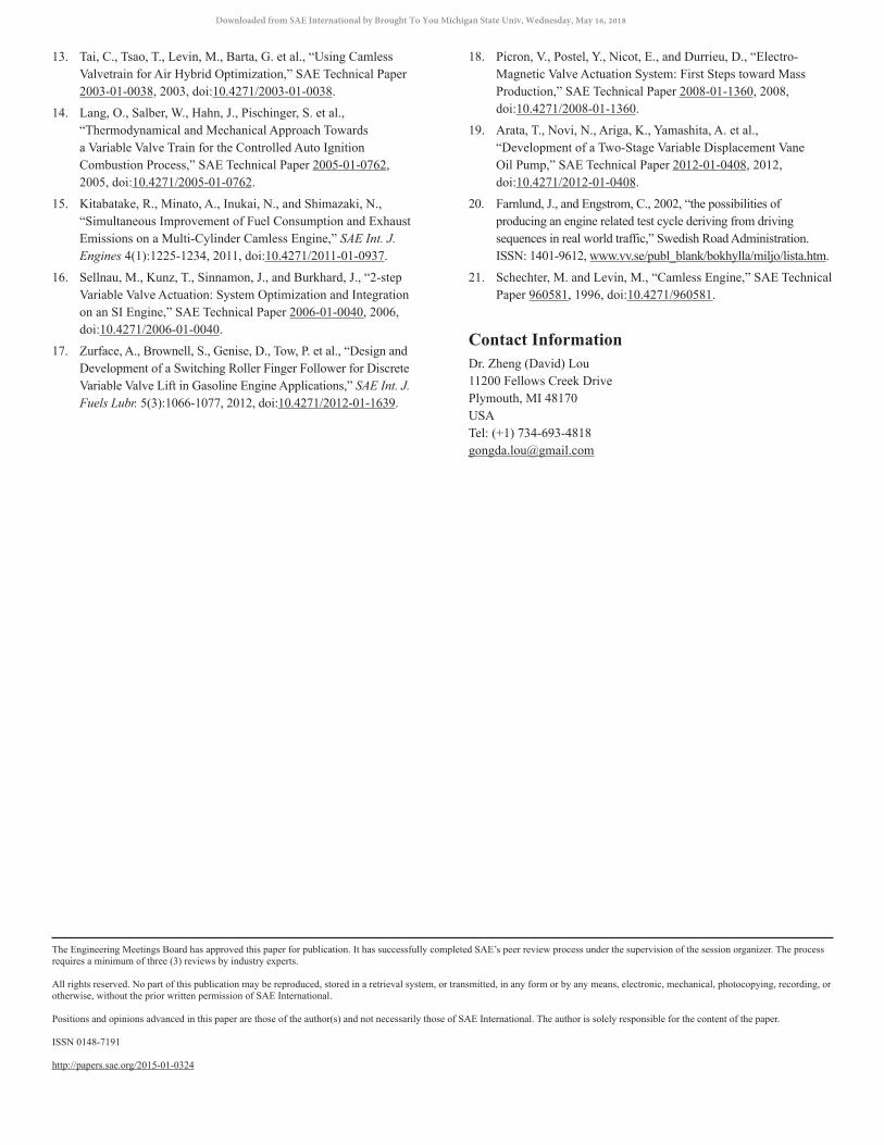
Energy ConsumptionDepending on design details and operating conditions, a traditional cam-driven valve system of a conventional gasoline engine consumes between 1.5 and 4.0 Joules of energy for each operation or cycle (i.e., an open-close cycle, including the dwell time). Some OEM requires that a camless VVA consumes no more than 2.0 Joules of energy per cycle. GD-VVA-2 prototypes are measured, for intake valve operation, to consume about 3.7 Joules and 1.8 Joules at 8 mm (high) and 4 mm (low) lift operations, respectively. It is estimated that the power consumption will be about 0.5 Joules and 1.0 Joules higher for exhaust valve operation at 4 mm and 8 mm, respectively. Combining these measured and estimated data, the overall power consumption is depicted in Figure 16. It is for a 4-cylinder 16-valve gasoline engine, with the following considerations and/or assumptions:
1. The hydraulic system includes a variable displacement pump with an overall efficiency of 80%.
2. For engine speed at 4000 rpm or lower (almost 100% of of a typical drive cycle [20]), a low lift of 4mm is sufficient for the air exchange, especially considering a fuller valve profile made possible by the camless design.
3. For low and medium load operations, it is possible to activate only one of two intake or exhaust valves in each cylinder, i.e., single-valve operation (vs. traditional double-valve operation).
Downloaded from SAE International by Brought To You Michigan State Univ, Wednesday, May 16, 2018
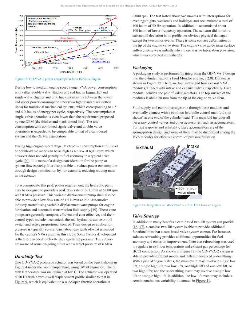
Figure 16. GD-VVA-2 power consumption for a 16-Valve Engine
During low to medium engine speed range, VVA power consumption with either double-valve (thicker and red line in Figure 16) and single-valve (lighter and blue line) operation is between the lower and upper power consumption lines (two lighter and black dotted lines) for traditional mechanical systems, which corresponding to 1.5 and 4.0 Joules of energy per cycle, respectively. The consumption at single-valve operation is even lower than the requirement proposed by one OEM (the thicker and black dotted line). The total consumption with combined signle-valve and double-valve operations is expected to be comparable to that of a cam-based system and the OEM's expectation.
During high engine speed range, VVA power consumption at full load or double-valve mode can be as high as 4.8 kW at 6,000rpm, which however does not add penalty to fuel economy in a typical drive cycle [20]. It is more of a design consideration for the pump or system flow capacity. It is also possible to reduce power consumption through design optimization by, for example, reducing moving mass in the actuator.
To accommodate this peak power requirement, the hydraulic pump may be designed to provide a peak flow rate of 36 L/min at 6,000 rpm with 8 MPa pressure. This variable displacement pump shall also be able to provide a low flow rate of 1.3 L/min at idle. Automotive industry started using variable displacement vane pumps for engine lubrication and automatic transmission fluid supply [19]. These vane pumps are generally compact, efficient and cost-effective, and their control types include mechanical, thermal hydraulic, active on-off switch and active proportional control. Their design or application pressure is typically several bars, about one tenth of what is needed for the camless VVA system in this study. Some further development is therefore needed to elevate their operating pressure. The authors are aware of some on-going effort with a target pressure of 6 MPa.
Durability TestOne GD-VVA-2 prototype actuator was tested on the bench shown in Figure 4 under the room temperature, using 0W30 engine oil. The oil tank temperature was maintained at 60° C. The actuator was operated at 50 Hz with a zero-dwell displacement profile similar to that in Figure 9, which is equivalent to a wide-open throttle operation at
6,000 rpm. The test lasted about two months with interruptions for evenings/nights, weekends and holidays, and accumulated a total of 400 hours of 50 Hz operation. In addition, it accumulated about 100 hours of lower frequency operation. The actuator did not show substantial deviation in its profile nor obvious physical damages except for two minor events. There is some contact deformation on the tip of the engine valve stem. The engine valve guide inner surface suffered some wear initially when there was no lubrication provision, which was corrected immediately.
PackagingA packaging study is performed by integrating the GD-VVA-2 design into the cylinder head of a Ford Mondeo engine, a 2.0L Duratec as shown in Figure 17. There are four intake and four exhaust VVA modules, aligned with intake and exhaust valves respectively. Each module includes one pair of valve actuators. The top surface of the modules is about 80 mm from the tip of the engine valve stem.
Fluid supply and control passages run through these modules and eventually connect with a common hydraulic control manifold (not shown) at one end of the cylinder head. This manifold includes all necessary control valves and other accessories, such as accumulators. For fast response and reliability, these accumulators are of the spring-piston design, and some of them may be distributed among the VVA modules for effective control of pressure pulsation.
Figure 17. Integration of GD-VVA-2 in a 2.0L Ford Duratec engine.
Valve StrategyIn addition to many benefits a cam-based two-lift system can provide [16, 17], a camless two-lift system is able to provide additional functionalities that a cam-based valve system cannot. For instance, exhaust rebreathing provides additional opportunities for fuel economy and emission improvement. Note that rebreathing was used to regulate in-cylinder temperature and exhaust gas percentage for HCCI combustion. As shown in Figure 18, the GD-VVA-2 system is able to provide different modes and different levels of re-breathing. With a pair of engine valves, the main event may involve a single low lift, a single high lift, two low lifts, one high lift and one low lift, or two high lifts; and the re-breathing event may involve a single low lift or a single high lift. In addition, the low lift event may include a certain continuous variability illustrated in Figure 11.
Downloaded from SAE International by Brought To You Michigan State Univ, Wednesday, May 16, 2018
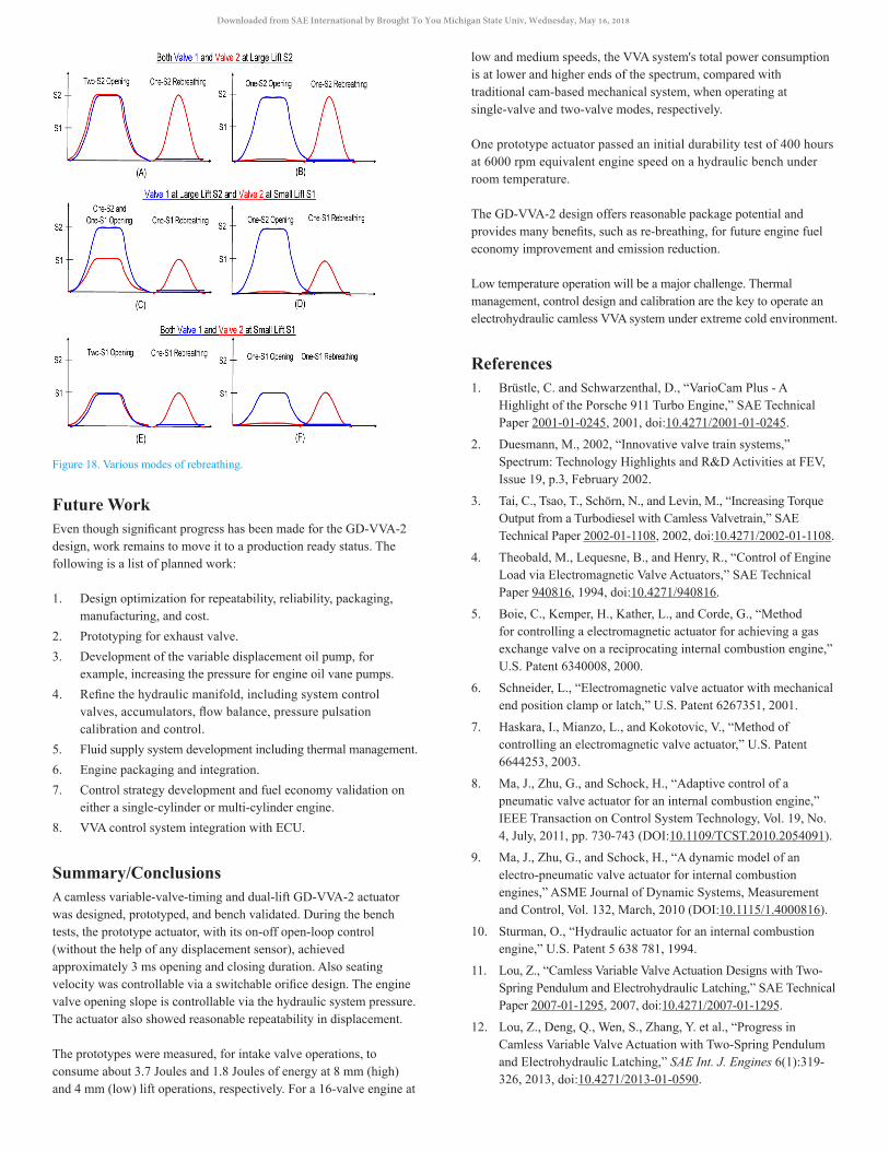
Figure 18. Various modes of rebreathing.
Future WorkEven though significant progress has been made for the GD-VVA-2 design, work remains to move it to a production ready status. The following is a list of planned work:
1. Design optimization for repeatability, reliability, packaging, manufacturing, and cost.
2. Prototyping for exhaust valve. 3. Development of the variable displacement oil pump, for
example, increasing the pressure for engine oil vane pumps. 4. Refine the hydraulic manifold, including system control
valves, accumulators, flow balance, pressure pulsation calibration and control.
5. Fluid supply system development including thermal management. 6. Engine packaging and integration. 7. Control strategy development and fuel economy validation on
either a single-cylinder or multi-cylinder engine. 8. VVA control system integration with ECU.
Summary/ConclusionsA camless variable-valve-timing and dual-lift GD-VVA-2 actuator was designed, prototyped, and bench validated. During the bench tests, the prototype actuator, with its on-off open-loop control (without the help of any displacement sensor), achieved approximately 3 ms opening and closing duration. Also seating velocity was controllable via a switchable orifice design. The engine valve opening slope is controllable via the hydraulic system pressure. The actuator also showed reasonable repeatability in displacement.
The prototypes were measured, for intake valve operations, to consume about 3.7 Joules and 1.8 Joules of energy at 8 mm (high) and 4 mm (low) lift operations, respectively. For a 16-valve engine at
low and medium speeds, the VVA system's total power consumption is at lower and higher ends of the spectrum, compared with traditional cam-based mechanical system, when operating at single-valve and two-valve modes, respectively.
One prototype actuator passed an initial durability test of 400 hours at 6000 rpm equivalent engine speed on a hydraulic bench under room temperature.
The GD-VVA-2 design offers reasonable package potential and provides many benefits, such as re-breathing, for future engine fuel economy improvement and emission reduction.
Low temperature operation will be a major challenge. Thermal management, control design and calibration are the key to operate an electrohydraulic camless VVA system under extreme cold environment.
References1. Brüstle, C. and Schwarzenthal, D., “VarioCam Plus - A
Highlight of the Porsche 911 Turbo Engine,” SAE Technical Paper 2001-01-0245, 2001, doi:10.4271/2001-01-0245.
2. Duesmann, M., 2002, “Innovative valve train systems,” Spectrum: Technology Highlights and R&D Activities at FEV, Issue 19, p.3, February 2002.
3. Tai, C., Tsao, T., Schörn, N., and Levin, M., “Increasing Torque Output from a Turbodiesel with Camless Valvetrain,” SAE Technical Paper 2002-01-1108, 2002, doi:10.4271/2002-01-1108.
4. Theobald, M., Lequesne, B., and Henry, R., “Control of Engine Load via Electromagnetic Valve Actuators,” SAE Technical Paper 940816, 1994, doi:10.4271/940816.
5. Boie, C., Kemper, H., Kather, L., and Corde, G., “Method for controlling a electromagnetic actuator for achieving a gas exchange valve on a reciprocating internal combustion engine,” U.S. Patent 6340008, 2000.
6. Schneider, L., “Electromagnetic valve actuator with mechanical end position clamp or latch,” U.S. Patent 6267351, 2001.
7. Haskara, I., Mianzo, L., and Kokotovic, V., “Method of controlling an electromagnetic valve actuator,” U.S. Patent 6644253, 2003.
8. Ma, J., Zhu, G., and Schock, H., “Adaptive control of a pneumatic valve actuator for an internal combustion engine,” IEEE Transaction on Control System Technology, Vol. 19, No. 4, July, 2011, pp. 730-743 (DOI:10.1109/TCST.2010.2054091).
9. Ma, J., Zhu, G., and Schock, H., “A dynamic model of an electro-pneumatic valve actuator for internal combustion engines,” ASME Journal of Dynamic Systems, Measurement and Control, Vol. 132, March, 2010 (DOI:10.1115/1.4000816).
10. Sturman, O., “Hydraulic actuator for an internal combustion engine,” U.S. Patent 5 638 781, 1994.
11. Lou, Z., “Camless Variable Valve Actuation Designs with Two-Spring Pendulum and Electrohydraulic Latching,” SAE Technical Paper 2007-01-1295, 2007, doi:10.4271/2007-01-1295.
12. Lou, Z., Deng, Q., Wen, S., Zhang, Y. et al., “Progress in Camless Variable Valve Actuation with Two-Spring Pendulum and Electrohydraulic Latching,” SAE Int. J. Engines 6(1):319-326, 2013, doi:10.4271/2013-01-0590.
Downloaded from SAE International by Brought To You Michigan State Univ, Wednesday, May 16, 2018
13. Tai, C., Tsao, T., Levin, M., Barta, G. et al., “Using Camless Valvetrain for Air Hybrid Optimization,” SAE Technical Paper 2003-01-0038, 2003, doi:10.4271/2003-01-0038.
14. Lang, O., Salber, W., Hahn, J., Pischinger, S. et al., “Thermodynamical and Mechanical Approach Towards a Variable Valve Train for the Controlled Auto Ignition Combustion Process,” SAE Technical Paper 2005-01-0762, 2005, doi:10.4271/2005-01-0762.
15. Kitabatake, R., Minato, A., Inukai, N., and Shimazaki, N., “Simultaneous Improvement of Fuel Consumption and Exhaust Emissions on a Multi-Cylinder Camless Engine,” SAE Int. J. Engines 4(1):1225-1234, 2011, doi:10.4271/2011-01-0937.
16. Sellnau, M., Kunz, T., Sinnamon, J., and Burkhard, J., “2-step Variable Valve Actuation: System Optimization and Integration on an SI Engine,” SAE Technical Paper 2006-01-0040, 2006, doi:10.4271/2006-01-0040.
17. Zurface, A., Brownell, S., Genise, D., Tow, P. et al., “Design and Development of a Switching Roller Finger Follower for Discrete Variable Valve Lift in Gasoline Engine Applications,” SAE Int. J. Fuels Lubr. 5(3):1066-1077, 2012, doi:10.4271/2012-01-1639.
18. Picron, V., Postel, Y., Nicot, E., and Durrieu, D., “Electro-Magnetic Valve Actuation System: First Steps toward Mass Production,” SAE Technical Paper 2008-01-1360, 2008, doi:10.4271/2008-01-1360.
19. Arata, T., Novi, N., Ariga, K., Yamashita, A. et al., “Development of a Two-Stage Variable Displacement Vane Oil Pump,” SAE Technical Paper 2012-01-0408, 2012, doi:10.4271/2012-01-0408.
20. Farnlund, J., and Engstrom, C., 2002, “the possibilities of producing an engine related test cycle deriving from driving sequences in real world traffic,” Swedish Road Administration. ISSN: 1401-9612, www.vv.se/publ_blank/bokhylla/miljo/lista.htm.
21. Schechter, M. and Levin, M., “Camless Engine,” SAE Technical Paper 960581, 1996, doi:10.4271/960581.
Contact InformationDr. Zheng (David) Lou11200 Fellows Creek DrivePlymouth, MI 48170USATel: (+1) [email protected]
The Engineering Meetings Board has approved this paper for publication. It has successfully completed SAE’s peer review process under the supervision of the session organizer. The process requires a minimum of three (3) reviews by industry experts.
All rights reserved. No part of this publication may be reproduced, stored in a retrieval system, or transmitted, in any form or by any means, electronic, mechanical, photocopying, recording, or otherwise, without the prior written permission of SAE International.
Positions and opinions advanced in this paper are those of the author(s) and not necessarily those of SAE International. The author is solely responsible for the content of the paper.
ISSN 0148-7191
http://papers.sae.org/2015-01-0324
Downloaded from SAE International by Brought To You Michigan State Univ, Wednesday, May 16, 2018