camshaft timing chain, sprocket, and …chain+-+ecotec.pdfcamshaft timing chain, sprock... camshaft...
TRANSCRIPT
CAMSHAFT TIMING CHAIN, SPROCK...
CAMSHAFT TIMING CHAIN, SPROCKET, AND TENSIONER INSTALLATION (ENGINEMECHANICAL 2.0L)
Document ID#1654359
Camshaft Timing Chain, Sprocket, and Tensioner Installation
Tools Required
J 45027 Tensioner ToolJ 45059 Angle Meter
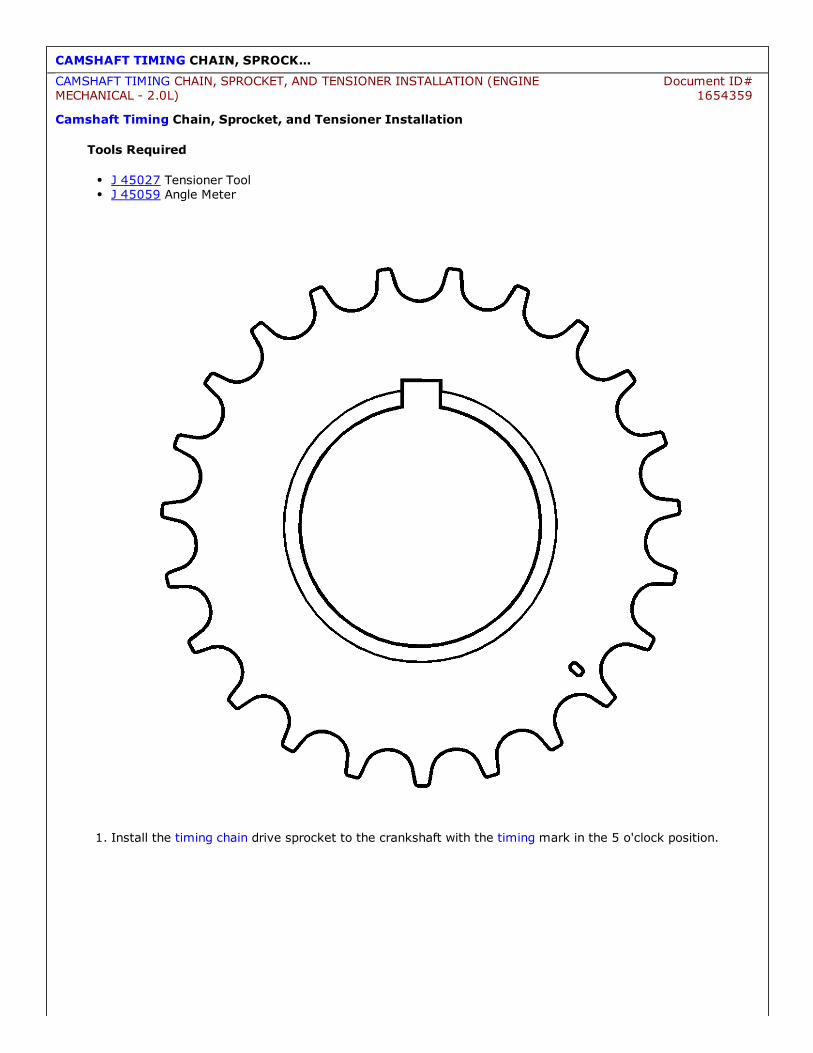
1. Install the timing chain drive sprocket to the crankshaft with the timing mark in the 5 o'clock position.
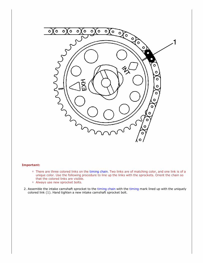
Important:
There are three colored links on the timing chain. Two links are of matching color, and one link is of aunique color. Use the following procedure to line up the links with the sprockets. Orient the chain sothat the colored links are visible.Always use new sprocket bolts.
2. Assemble the intake camshaft sprocket to the timing chain with the timing mark lined up with the uniquelycolored link (1). Hand tighten a new intake camshaft sprocket bolt.

3. Lower the timing chain through the opening in the cylinder head. Use care to ensure that the chain goesaround both sides of the cylinder block bosses (1,2).

4. Route the timing chain around the crankshaft sprocket and line up the first matching colored link (2) withthe timing mark on the crankshaft sprocket, in approximately the 5 o'clock position.
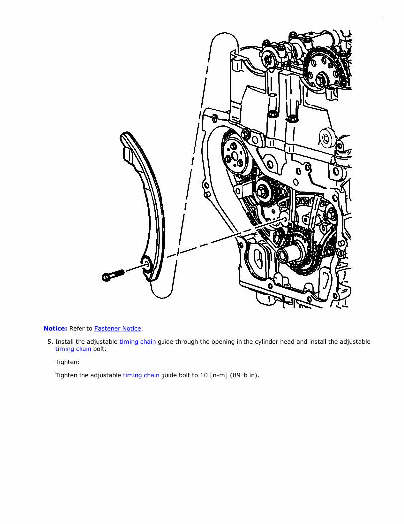
Notice: Refer to Fastener Notice.
5. Install the adjustable timing chain guide through the opening in the cylinder head and install the adjustabletiming chain bolt.
Tighten:
Tighten the adjustable timing chain guide bolt to 10 [nm] (89 lb in).
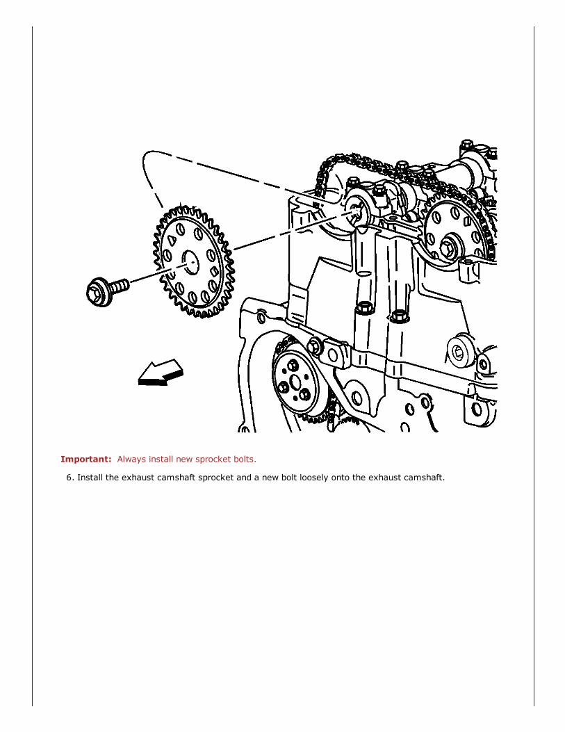
Important: Always install new sprocket bolts.
6. Install the exhaust camshaft sprocket and a new bolt loosely onto the exhaust camshaft.

7. Align the timing mark on the sprocket with the last matching colored link (3). Install the bolt finger tight.
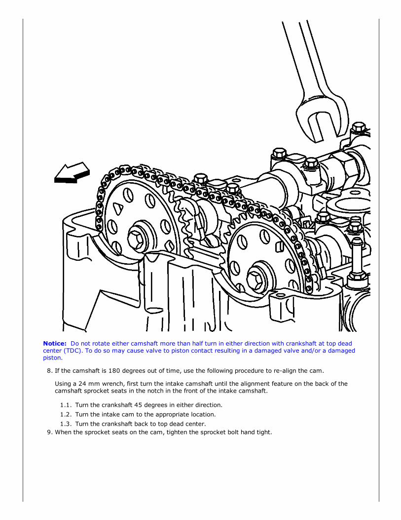
Notice: Do not rotate either camshaft more than half turn in either direction with crankshaft at top deadcenter (TDC). To do so may cause valve to piston contact resulting in a damaged valve and/or a damagedpiston.
8. If the camshaft is 180 degrees out of time, use the following procedure to realign the cam.
Using a 24 mm wrench, first turn the intake camshaft until the alignment feature on the back of thecamshaft sprocket seats in the notch in the front of the intake camshaft.
1.1. Turn the crankshaft 45 degrees in either direction.1.2. Turn the intake cam to the appropriate location.1.3. Turn the crankshaft back to top dead center.
9. When the sprocket seats on the cam, tighten the sprocket bolt hand tight.

10. Verify that all of the colored links and the appropriate timing marks are still aligned. If they are not, repeatthe portion of the procedure necessary to align the timing marks.

11. Install the fixed timing chain guide.
Tighten:
Tighten the fixed timing chain guide bolts to 10 [nm] (89 lb in).

12. Install the upper timing chain guide.
Tighten:
Tighten the upper timing chain guide bolts to 10 [nm] (89 lb in).
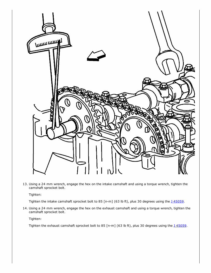
13. Using a 24 mm wrench, engage the hex on the intake camshaft and using a torque wrench, tighten thecamshaft sprocket bolt.
Tighten:
Tighten the intake camshaft sprocket bolt to 85 [nm] (63 lb ft), plus 30 degrees using the J 45059.
14. Using a 24 mm wrench, engage the hex on the exhaust camshaft and using a torque wrench, tighten thecamshaft sprocket bolt.
Tighten:
Tighten the exhaust camshaft sprocket bolt to 85 [nm] (63 lb ft), plus 30 degrees using the J 45059.
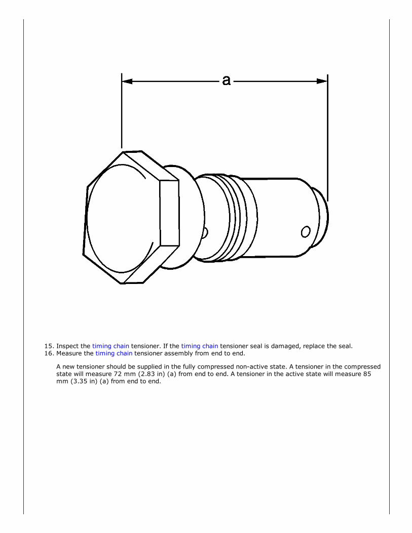
15. Inspect the timing chain tensioner. If the timing chain tensioner seal is damaged, replace the seal.16. Measure the timing chain tensioner assembly from end to end.
A new tensioner should be supplied in the fully compressed nonactive state. A tensioner in the compressedstate will measure 72 mm (2.83 in) (a) from end to end. A tensioner in the active state will measure 85mm (3.35 in) (a) from end to end.

17. If the timing chain tensioner is not in the compressed state, perform the following steps:1.1. Remove the piston assembly from the body of the timing chain tensioner by pulling it out.1.2. Install the J 450272 (2) into a vise.1.3. Install the notch end of the piston assembly into the J 450272 (2).1.4. Using the J 450271 (1), turn the ratchet cylinder into the piston.
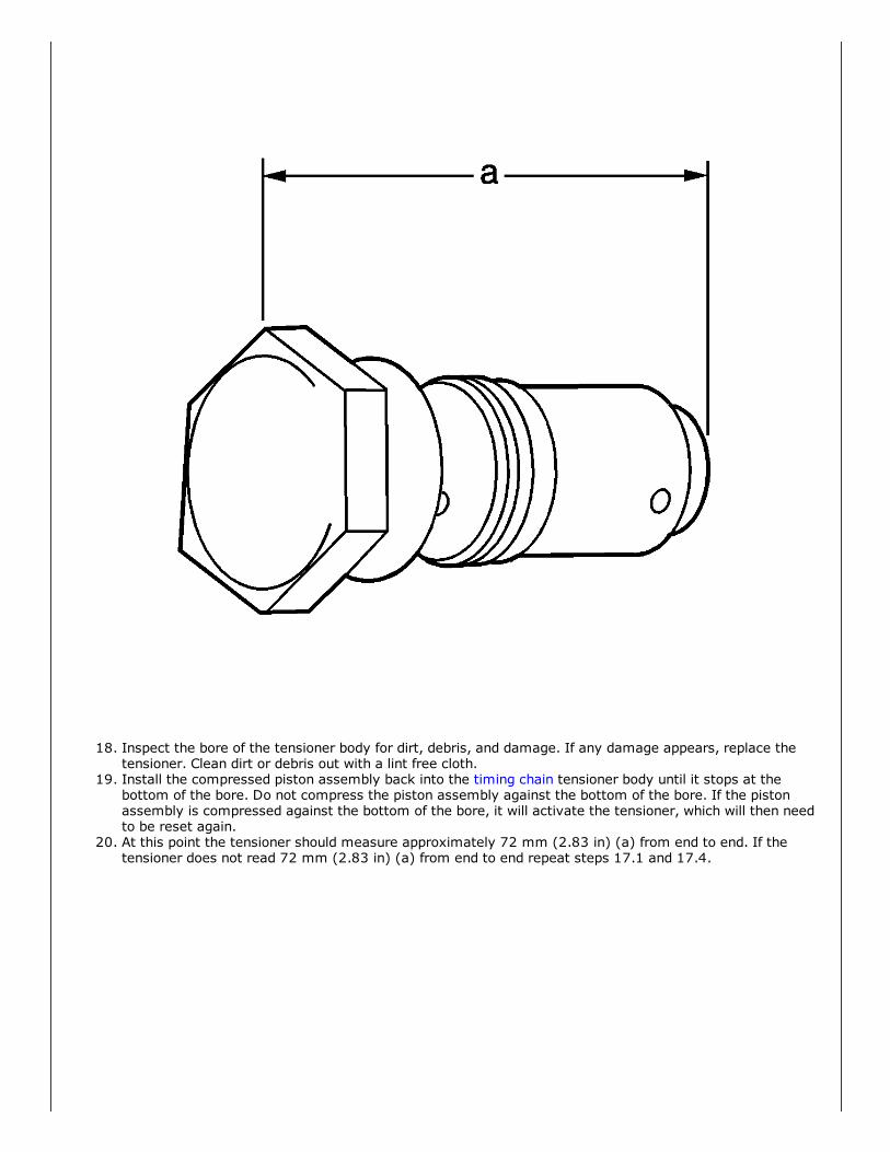
18. Inspect the bore of the tensioner body for dirt, debris, and damage. If any damage appears, replace thetensioner. Clean dirt or debris out with a lint free cloth.
19. Install the compressed piston assembly back into the timing chain tensioner body until it stops at thebottom of the bore. Do not compress the piston assembly against the bottom of the bore. If the pistonassembly is compressed against the bottom of the bore, it will activate the tensioner, which will then needto be reset again.
20. At this point the tensioner should measure approximately 72 mm (2.83 in) (a) from end to end. If thetensioner does not read 72 mm (2.83 in) (a) from end to end repeat steps 17.1 and 17.4.
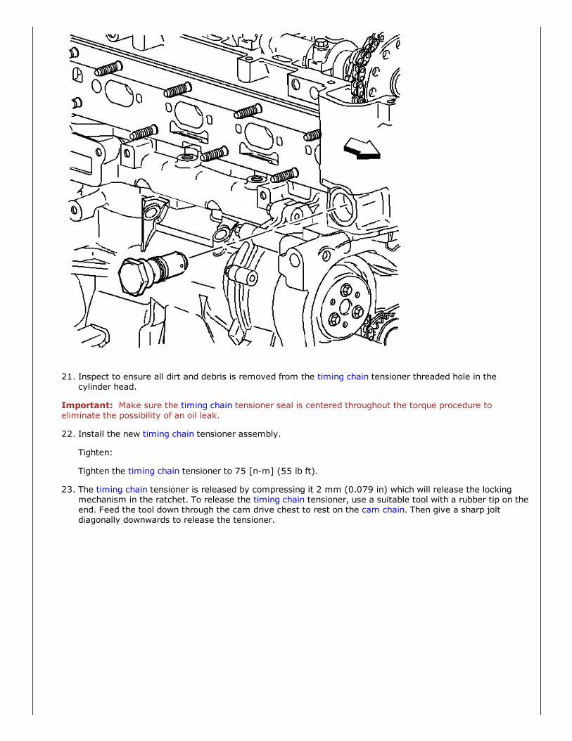
21. Inspect to ensure all dirt and debris is removed from the timing chain tensioner threaded hole in thecylinder head.
Important: Make sure the timing chain tensioner seal is centered throughout the torque procedure toeliminate the possibility of an oil leak.
22. Install the new timing chain tensioner assembly.
Tighten:
Tighten the timing chain tensioner to 75 [nm] (55 lb ft).
23. The timing chain tensioner is released by compressing it 2 mm (0.079 in) which will release the lockingmechanism in the ratchet. To release the timing chain tensioner, use a suitable tool with a rubber tip on theend. Feed the tool down through the cam drive chest to rest on the cam chain. Then give a sharp joltdiagonally downwards to release the tensioner.

24. Install the timing chain oiling nozzle.
Tighten:
Tighten the timing chain oiling nozzle bolt to 10 [nm] (89 lb in).

25. Apply sealant GM P/N 12345382 (Canadian P/N 10953489) or equivalent to the thread, and install thetiming chain guide bolt access hole plug.
Tighten:
Tighten the access hole plug to 90 [nm] (66 lb ft).
"Portions of materials contained herein have been reprinted with permission of General Motors Corporation, Serviceand Parts Operations" License Agreement #0410810.
Copyright 2007 2012 Service Repair Solutions, Inc.