can my synthesis compiler do that? - sutherland · pdf filecan my synthesis compiler do that?...
TRANSCRIPT
©2014, Sutherland HDL, Inc. www.sutherland-hdl.com presented at DVCon-2014, San Jose, CA
Can My Synthesis Compiler Do That?What ASIC and FPGA Synthesis Compilers Support in the
SystemVerilog-2012 Standard
ABSTRACT
There seems to be an industry-wide misconception that the Verilog language is used for design andsynthesis, and SystemVerilog is only used for verification. The authors have often heard comments fromengineers such as, “Our synthesis compiler does not support SystemVerilog”, “Our [design]management is afraid of SystemVerilog” and, from a synthesis company’s support engineer, “Can ourcompiler do that?”
The truth is, when the SystemVerilog standard was first conceived in 2002, one of the primary goalswas to enable creating synthesizable models of complex hardware designs more accurately and withfewer lines of code. A great deal of SystemVerilog was intended to be used for design and synthesis.That goal was achieved, and all major ASIC and FPGA synthesis compilers support a large portion ofSystemVerilog. This paper examines several synthesizable SystemVerilog constructs, and presents theadvantages of using these constructs over traditional Verilog. Readers will take away from this papernew RTL modeling skills that will indeed enable modeling designs with fewer lines of code, while at thesame time reducing potential design errors and achieving high synthesis Quality of Results (QoR).
Target audience: Engineers involved in RTL design and synthesis, targeting complex ASIC and FPGAimplementations.
Stuart SutherlandSutherland HDL, Inc.
Don MillsMicrochip Technology, Inc.
©2014, Sutherland HDL, Inc. www.sutherland-hdl.com presented at DVCon-2014, San Jose, CA2
Table of Contents1. Introduction ............................................................... 22. Verilog versus SystemVerilog ................................... 23. Procedural blocks ...................................................... 34. Simplified net and variable declarations ................... 45. Vectors with subfields ............................................... 56. Enumerated types ...................................................... 67. Copying arrays ........................................................... 78. Structures ................................................................... 89. Packages .................................................................. 1010. Decision operators and statements .......................... 11
10.1 Wildcard decisions (wildcard equality) .......... 1210.2 Set membership operator (inside) ................... 1210.3 Case...inside decisions .................................... 1210.4 Unique, unique0 and priority decision checks 13
11. Streaming operators ................................................. 1412. Casting ..................................................................... 1513. Tasks and functions ................................................. 1714. Interfaces ................................................................. 1815. Vector fill tokens .....................................................1916. Expression size functions ........................................ 2017. Synthesis compiler support for SystemVerilog ....... 2118. Additional synthesizable SystemVerilog constructs 2119. Summary .................................................................. 2220. Conclusion ............................................................... 2321. Acknowledgements ................................................. 2322. References ............................................................... 23Appendix A: Table of synthesis compiler support ......... 24
1.0 Introduction
There is a common misconception that “Verilog” is ahardware modeling language that is synthesizable, and“SystemVerilog” is a verification language that is notsynthesizable. This is not true! Much of SystemVerilog issynthesizable with today’s ASIC and FPGA synthesiscompilers. This paper poses several questions, and showswhy it is important to use SystemVerilog for synthesis.
1. Can my synthesis compiler actually tell me when Ihave the wrong type of logic in my RTL models?
2. Can my synthesis compiler infer nets and variableswithout my having to worry about where to use regand where to use wire?
3. Can my synthesis compiler work with bytes of a vectorwithout using complex and cryptic vector part selects?
4. Can my synthesis compiler prevent me from assigningstupid values to variables?
5. Can my synthesis compiler copy an entire look-uptable or register file in a single statement?
6. Can my synthesis compiler use 4 lines of code toreplace 216 lines of code?
7. Can my synthesis compiler handle defining functions,constants, and other declarations in just one place, and
using those definitions in multiple modules?
8. Can my synthesis compiler help me make betterdecisions?
9. Can my synthesis compiler reverse all the bits or bytesof my parameterized-width data word in oneoperation?
10. Can my synthesis compiler eliminate false warningmessages about intentional size and type conversions,and only warn about unintentional conversions?
11. Can my synthesis compiler prevent me from writingtasks (subroutines) that simulate, but won’t synthesize?
12. Can my synthesis compiler support modeling standardbus protocol signals at a higher level of abstraction thatavoids code duplication?
13. Can my synthesis compiler fill vectors of any size andwith parameterized widths with all 1s?
14. Can my synthesis compiler automatically calculate thesize of my address bus, based on the depth of mymemory storage?
The goal for this paper is to help engineers andengineering managers understand the advantages of usingSystemVerilog for RTL design and synthesis, rather thanlimit (or handcuff) themselves to the thirteen-year-oldVerilog-2001 language. Towards this end, this paperpresents only a few of the SystemVerilog constructs thatare synthesizable, and that offer significant advantagesover traditional Verilog. This paper does not discuss everysynthesizable SystemVerilog feature, and does not coverthe synthesizable constructs in traditional Verilog.
2. Verilog versus SystemVerilogVerilog was never just a design and synthesis language.Verilog has always been a dual-purpose language to beused to both model hardware functionality and to describeverification testbenches. Verilog synthesis compilers onlysupport a subset of the Verilog language, the portion thatcan be represented in actual silicon. It is a misconceptionthat Verilog is strictly for design and synthesis.
The original Verilog language was a simple language firstintroduced in the early 1980s. Design size and complexityhave grown at a tremendous rate since the Verilog languagewas created, and, although Verilog was a very capablelanguage for modeling the size, complexity and speed ofsilicon chips being designed in the 1980s and 1990s, thecomplexity of designs in the 2000s require a much morecapable modeling and verification language.
The confusing name change... In 2002, a standardscommittee was formed to extend the capabilities ofVerilog. (One of the authors of this paper was a foundingmember of this committee.) The new features being addedwere so substantial that this standards committee decided
©2014, Sutherland HDL, Inc. www.sutherland-hdl.com presented at DVCon-2014, San Jose, CA3
to give Verilog a new name, SystemVerilog. (The standardscommittee also considered “Verilog++” as a new name, butfelt “SystemVerilog” would have more market appeal.) In2009, the IEEE officially terminated support for the earlierstandards that used the Verilog name, and now only usesthe SystemVerilog name. Whether you knew it or not,since 2009, you have not been using Verilog for yourdesign projects...you have been designing with—andsynthesizing—SystemVerilog!
This paper assumes that readers are already familiar withRTL modeling and synthesis with traditional Verilog, andfocuses on synthesizable constructs that SystemVerilogadds to traditional Verilog (the IEEE 1364-2001 Verilogstandard).
3. Procedural blocks
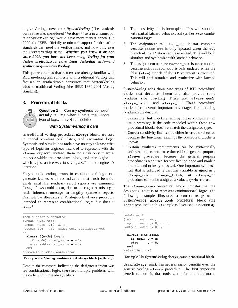
In traditional Verilog, procedural always blocks are usedto model combinational, latch, and sequential logic.Synthesis and simulations tools have no way to know whattype of logic an engineer intended to represent with thealways keyword. Instead, these tools can only interpretthe code within the procedural block, and then “infer” —which is just a nice way to say “guess” — the engineer’sintention.
Easy-to-make coding errors in combinational logic cangenerate latches with no indication that latch behaviorexists until the synthesis result reports are examined.Design flaws could occur, due to an engineer missing alatch inference message in lengthy synthesis reports.Example 3.a illustrates a Verilog-style always procedureintended to represent combinational logic, but does itreally?
module adder_subtractor(input wire mode, input wire [7:0] a, b, output reg [7:0] adder_out, subtractor_out); always @(mode) begin if (mode) adder_out = a + b; else subtractor_out = a - b; endendmodule //adder_subtractor
Example 3.a: Verilog combinational always block (with bug)
Despite the comment indicating the designer’s intent wasfor combinational logic, there are multiple problems withthe code within this always block.
1. The sensitivity list is incomplete. This will simulatewith partial latched behavior, but synthesize as combi-national logic.
2. The assignment to adder_out is not completebecause adder_out is only updated when the truebranch of the if statement is executed. This will bothsimulate and synthesize with latched behavior.
3. The assignment to subtractor_out is not completebecause subtractor_out is only updated when thefalse (else) branch of the if statement is executed.This will both simulate and synthesize with latchedbehavior.
SystemVerilog adds three new types of RTL proceduralblocks that document intent and also provide somesynthesis rule checking. These are: always_comb,always_latch, and always_ff. These proceduralblocks offer several important advantages for modelingsynthesizable designs:
• Simulators, lint checkers, and synthesis compilers canissue warnings if the code modeled within these newprocedural blocks does not match the designated type.
• Correct sensitivity lists can be either inferred or checkedbecause the functional intent of the procedural blocks isknown.
• Certain synthesis requirements can be syntacticallyenforced that cannot be enforced in a general purposealways procedure, because the general purposeprocedure is also used for verification code and modelsnot intended to be synthesized. One important synthesisrule that is enforced is that any variable assigned in aalways_comb, always_latch, or always_ffprocedure cannot be assigned a value anywhere else.
The always_comb procedural block indicates that thedesigner’s intent is to represent combinational logic. Thefollowing example illustrates a correct usage of aSystemVerilog always_comb procedural block (thelogic type used in this example is discussed in Section 4):
module mux8(input logic sel, input logic [7:0] a, b, output logic [7:0] y); always_comb begin if (sel) y = a; else y = b; endendmodule: mux8
Example 3.b: SystemVerilog always_comb procedural block
Using always_comb has several major benefits over thegeneric Verilog always procedure. The first importantbenefit to note is that tools can infer a combinatorial
Question 1 — Can my synthesis compileractually tell me when I have the wrongtype of logic in my RTL models?
With SystemVerilog it can!

©2014, Sutherland HDL, Inc. www.sutherland-hdl.com presented at DVCon-2014, San Jose, CA4
sensitivity list, because tools know the intent of theprocedural block. A common coding mistake withtraditional Verilog is to have an incomplete sensitivity list.(Even Verilog’s always_@* will sometimes infer anincomplete sensitivity list.) This is not a syntax error, andresults in RTL simulation behaving differently than thepost-synthesis gate-level implementation of the design.Inadvertently leaving out a signal from the sensitivity list isan easy mistake to make in large, complex decoding logic.
Another important benefit is that, because software toolsknow the intent is to represent combinational logic, toolscan verify that this intent is being met. Example 3.c showsthe same code as in Example 3.a, with the same codingerrors, but this time modeled SystemVerilog stye, usingalways_comb. (Note that the incomplete sensitivity listerror in Example 3.a cannot be made with always_comb.)
module adder_subtractor(input wire mode, input wire [7:0] a, b, output reg [7:0] adder_out, subtractor_out); always_comb begin if (mode) adder_out = a + b; else subtractor_out = a - b; endendmodule: adder_subtractor
Example 3.c: always_comb procedure with latch behavior
When traditional Verilog always procedures aresynthesized, synthesis compilers cannot tell if inferredlatches are intentional or unintentional. Synthesiscompilers can only report how many latches were inferred,and not whether the latch was due to a coding error. WithSystemVerilog always_comb procedures, synthesiscompilers can report exactly where any unintentionallatches occurred. When the code for Example 3.c was readinto one synthesis compiler, the following elaborationwarning was issued:Warning: example03c.sv:6: Netlist for always_comb block contains a latch. (ELAB-974)
The always_latch procedural block is similar toalways_comb, except that it documents the designer’sintent to represent latch behavior. Tools can then verify thatthis intent is being met.
The always_ff procedural block documents thedesigner’s intent to represent flip-flop behavior.always_ff differs from always_comb, in that thesensitivity list must be specified by the designer. This isbecause software tools cannot infer the clock name andclock edge from the body of the procedural block. Nor cana tool infer whether the intent is to have synchronous orasynchronous reset behavior. The clock and resetinformation must be specified as part of the sensitivity list.
Software tools can verify whether the intent for flip-flopbehavior is being met in the body of the procedural block.In the following example, always_ff is used for code thatdoes not actually model a flip-flop.
module reg8(input logic sel, input logic [7:0] a, b, output logic [7:0] out); always_ff @(sel, a, b) if (sel) out = a; else out = b;endmodule: reg8
Example 3.d: always_ff procedural block with combinational sensitivity list (no clock)
The warning that is issued by one synthesis compiler is:Warning: example03d.sv:6: Netlist for always_ff block does not contain a flip-flop. (ELAB-976)
4. Simplified net and variable declarations
Traditional Verilog has two primary types of data, nets andvariables. There are a number of specific net data typekeywords and variable keywords, but the two used almostexclusively for ASIC and FPGA design are the wire nettype and reg variable type.
Verilog has strict rules on where net types, such as wire,must be used, and where they may be used, and wherevariable types, such as reg, must be used, and where theymay be used. Learning these rules has always been achallenge, and, even after learning the rules, getting themright in RTL code remains a challenge for many engineers.(eventually many engineers simply learn to recognize theerror messages when they use wire or reg incorrectly.)
The reg keyword can also be a source of confusion forengineers first learning Verilog. The word “reg” wouldseem to imply “register”. A common new-usermisconception is that whereever a reg variable is used in
SystemVerilog Advantage 1 — Thebenefits of using the SystemVerilogalways_comb, always_latch andalways_ff procedural blocks are huge!
They can prevent serious modeling errors, andthey enable software tools to verify that designintent has been met.
Question 2 — Can my synthesis compilerinfer nets and variables without my havingto worry about where to use reg andwhere to use wire?
With SystemVerilog it can!
©2014, Sutherland HDL, Inc. www.sutherland-hdl.com presented at DVCon-2014, San Jose, CA5
an RTL model, synthesis will infer hardware registers. Theconfusing truth is that ‘reg” does not mean “register” andthe reg data type does not infer hardware registers.
SystemVerilog solves both of these Verilog shortcomingswith a new keyword, logic. The full meaning of this newtype is beyond the scope of this paper. Its usage is what isimportant. When module ports or signals internal to amodule are declared as a logic type, simulation andsynthesis compilers will automatically infer a net orvariable based on context. Correctly choosing wire or regbecomes the job of the compiler instead of the designengineer!
Example 4.a illustrates this advantage using a model of asimple RTL adder.
module adder16(input logic [15:0] a, b, // infers wire nets input logic ci, // infers wire net output logic [15:0] sum, // infers variables output logic co // infers variable); always_comb {co,sum} = a + b + ci;endmodule: adder16
Example 4.a: SystemVerilog automatic net and variable types
Note: At the time this paper was written, some synthesiscompilers incorrectly inferred a variable type for input andinout ports instead of a wire type. This incorrect inferenceprevents an inout port from having multiple drivers.
5. Vectors with subfields
In traditional Verilog, vectors are declared by specifying arange of bits in square brackets, followed by the vectorname. The range is declared as:
[ most-significant_bit_number : least-significant_bit_number ]
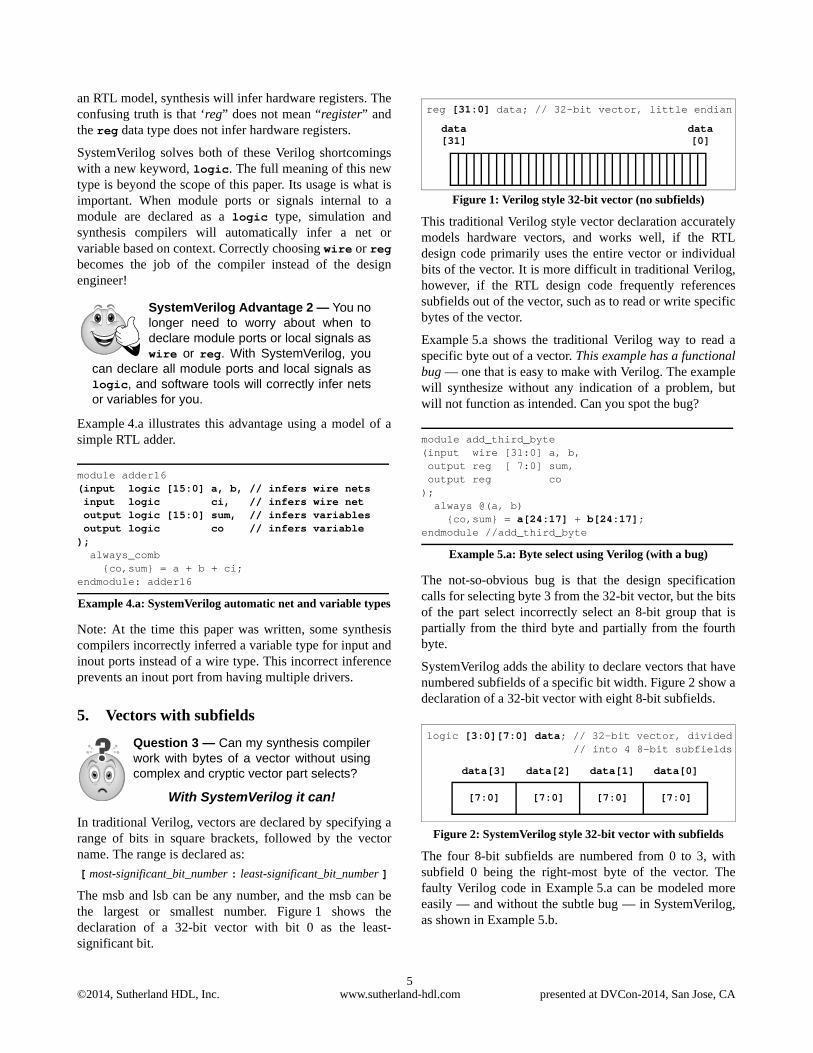
The msb and lsb can be any number, and the msb can bethe largest or smallest number. Figure 1 shows thedeclaration of a 32-bit vector with bit 0 as the least-significant bit.
Figure 1: Verilog style 32-bit vector (no subfields)
This traditional Verilog style vector declaration accuratelymodels hardware vectors, and works well, if the RTLdesign code primarily uses the entire vector or individualbits of the vector. It is more difficult in traditional Verilog,however, if the RTL design code frequently referencessubfields out of the vector, such as to read or write specificbytes of the vector.
Example 5.a shows the traditional Verilog way to read aspecific byte out of a vector. This example has a functionalbug — one that is easy to make with Verilog. The examplewill synthesize without any indication of a problem, butwill not function as intended. Can you spot the bug?
module add_third_byte(input wire [31:0] a, b, output reg [ 7:0] sum, output reg co); always @(a, b) {co,sum} = a[24:17] + b[24:17];endmodule //add_third_byte
Example 5.a: Byte select using Verilog (with a bug)
The not-so-obvious bug is that the design specificationcalls for selecting byte 3 from the 32-bit vector, but the bitsof the part select incorrectly select an 8-bit group that ispartially from the third byte and partially from the fourthbyte.
SystemVerilog adds the ability to declare vectors that havenumbered subfields of a specific bit width. Figure 2 show adeclaration of a 32-bit vector with eight 8-bit subfields.
Figure 2: SystemVerilog style 32-bit vector with subfields
The four 8-bit subfields are numbered from 0 to 3, withsubfield 0 being the right-most byte of the vector. Thefaulty Verilog code in Example 5.a can be modeled moreeasily — and without the subtle bug — in SystemVerilog,as shown in Example 5.b.
SystemVerilog Advantage 2 — You nolonger need to worry about when todeclare module ports or local signals aswire or reg. With SystemVerilog, you
can declare all module ports and local signals aslogic, and software tools will correctly infer netsor variables for you.
Question 3 — Can my synthesis compilerwork with bytes of a vector without usingcomplex and cryptic vector part selects?
With SystemVerilog it can!
reg [31:0] data; // 32-bit vector, little endian
data[31]
data[0]
logic [3:0][7:0] data; // 32-bit vector, divided// into 4 8-bit subfields
data[3]
[7:0]
data[2] data[1] data[0]
[7:0] [7:0] [7:0]

©2014, Sutherland HDL, Inc. www.sutherland-hdl.com presented at DVCon-2014, San Jose, CA6
module add_third_byte(input logic [3:0][7:0] a, b, // 32-bit vectors output logic [7:0] sum, output logic co); always_comb {co,sum} = a[2] + b[2]; // subfield selectsendmodule: add_third_byte
Example 5.b: Byte select using SystemVerilog
6. Enumerated types
Traditional Verilog nets and variables are loosely typed.Loosely typed nets and variables have built-in conversionrules that allow a value that is out-of-range, or of adifferent type, to be assigned. There is no checking of thevalue being assigned; the value is simply converted to thedata type of the net or variable.
Example 6.a shows code for a small state machine modeledwith traditional Verilog. The code is syntactically correct,and will synthesize, but, due to Verilog’s loosely typedbehavior, there are six functional bugs that will end up inthe gate-level implementation of the state-machine. (Somesynthesis compilers might issue a warning for some of thebugs, but the warnings are not fatal, and synthesis willimplement the bugs in the gate-level design.)
module controller(input wire clock, resetN, output reg [2:0] control);
// Names for state machine states (one-hot) parameter [2:0] WAIT = 3'b001, LOAD = 3'b010, DONE = 3'b001; // BUG 1
// Names for control output values parameter [1:0] READY = 3'b101, SET = 3'b010, GO = 3'b110; // BUG 2
// State and next state variables reg [2:0] state, n_state;
// State Sequencer always @(posedge clock or negedge resetN) if (!resetN) state <= 0; // BUG 3 else state <= n_state;
// Next State Decoder (sequentially cycle // through the three states) always @(state) case (state) WAIT: n_state = state+1; LOAD: n_state = state+1; // BUG 4 DONE: n_state = state+1; // BUG 5 endcase
// Output Decoder always @(state) case (state) WAIT: control = READY; LOAD: control = SET; DONE: control = DONE; // BUG 6 endcaseendmodule //controller
Example 6.a: Verilog state machine with 6 functional bugs
SystemVerilog adds enumerated type nets and variablesthat are more strongly typed. Enumerated types allow netsand variables to be defined with a specific set of namedvalues, referred to as labels. Designers can specify explicitvalues for each label.
Enumerated types have stronger rule checking than built-invariables and nets. These rules include:
• The value of each label in the enumerated list must beunique.
• The variable size and the size of the label values must bethe same.
• An enumerated variable can only be assigned:• A label from its enumerated list.• The value of another enumerated variable from the
same enumerated definition.
The stronger rules of enumerated types provide significantadvantages over traditional Verilog. Example 6.b is thesame state machine as the one previously shown inExample 6.a, but this time modeled using SystemVerilogenumerated types. Example 6.b has the same six bugs, but,with enumerated types, all six bugs become syntax errors.Neither simulators nor synthesis compilers will not allowthis faulty state machine to be implemented in gates untilthese bugs are fixed.
module controller(input logic clock, resetN, output logic [2:0] control_out);
// Enumerated variables for fsm states// One-hot encoding for the labelsenum logic [2:0] {WAIT = 3'b001,
SystemVerilog Advantage 3 — Designs that frequently manipulateparts of a vector are simpler to model,more self-documenting, and correct by
construction.
Question 4 — Can my synthesis compilerprevent me from assigning stupid values tovariables?
With SystemVerilog it can!
©2014, Sutherland HDL, Inc. www.sutherland-hdl.com presented at DVCon-2014, San Jose, CA7
LOAD = 3'b010, DONE = 3'b001} // SYNTAX ERROR
state, n_state;
// Enumerated variables for control output valuesenum logic [1:0] {READY = 3'b101, SET = 3'b010, GO = 3'b110} // SYNTAX ERROR
control;
assign control_out = control;
// State Sequencer always_ff @(posedge clock or negedge resetN) if (!resetN) state <= 0; // SYNTAX ERROR else state <= n_state;
// Next State Decoder (sequentially cycle // through the three states) always_comb case (state) WAIT: n_state = state + 1; // SYNTAX ERROR LOAD: n_state = state + 1; // SYNTAX ERROR DONE: n_state = state + 1; // SYNTAX ERROR endcase
// Output Decoder always_comb case (state) WAIT: control = READY; LOAD: control = SET; DONE: control = DONE; // SYNTAX ERROR endcaseendmodule: controller
Example 6.b: SystemVerilog style state machine with 6 bugs
7. Copying arrays
Traditional Verilog supports one-dimensional and multi-dimensional arrays, which, in RTL models, can be used torepresent look-up tables and register files. However,traditional Verilog only permits access to a single elementof an array at a time. To copy data from one array toanother array requires writing loops that index througheach element of each array.
Example 7.a illustrates copying the contents of a 3-dimensional register file into a second register file. Each
register file stores 16 8-bit values for red, green, and blue,giving a total of 48 bytes.
The restriction in Verilog that arrays can only be copiedone element at a time also makes it difficult to pass anarray through module ports. Passing signals through portsis a form of a continuous assignment. Since arrays can onlybe assigned one element at a time, to pass the array throughthe module port it is necessary to either:
• Create a separate port for each element of the array.• Create a vector port that is wide enough to contain all
elements of the array as if the array were concatenatedtogether.
Creating separate ports for each array element is simple,but only practical for very small arrays. Defining a vectorport wide enough to represent the entire array reduces thenumber of ports, but requires extra programming. Anoutput port require using loops to iterate through the arrayand assigning each element of the array to a part-select ofthe port vector, often referred to as “packing” the array intothe vector. An input port requires using loops to iterate thearray and unpacking the vector by assigning vector partselects to the corresponding array elements.
Example 7.a. shows that, even for a simple design with asmall array, the code to copy arrays and pass an arraythrough a port is complex and convoluted.
module rgb_frame_collector(input wire [7:0] red, green, blue, input wire clk, rstn, output reg frame_ready,// NEXT LINE IS A VECTOR PORT TO PASS AN ARRAY
output reg [383:0] rgb_frame_out); // internal arrays (16x3 arrays of bytes) reg [7:0] rgb_frame1 [0:15][0:2]; reg [7:0] rgb_frame2 [0:15][0:2];
// internal temporary variables reg [3:0] frame_addr; integer i, j;
// load arrays always @(posedge clk, negedge rstn) if (!rstn) begin frame_addr <= 0; frame_ready = 0; // RESET ARRAYS USING LOOPS: for (i=0; i<=15; i=i+1) begin for (j=0; j<=2; j=j+1) begin rgb_frame1[i][j] <= 0; rgb_frame2[i][j] <= 0; end end end else begin // as red/green/blue bytes come in, store // them in the rgb_frame1 array
SystemVerilog Advantage 4 — Enumerated types can prevent codingerrors that could be difficult to detectand debug!
Question 5 — Can my synthesis compilercopy an entire look-up table or register filein a single statement?
With SystemVerilog it can!
©2014, Sutherland HDL, Inc. www.sutherland-hdl.com presented at DVCon-2014, San Jose, CA8
frame_ready <= 0; rgb_frame1[frame_addr][0] <= red; rgb_frame1[frame_addr][1] <= green; rgb_frame1[frame_addr][2] <= blue; frame_addr <= frame_addr + 1;
// COPY ARRAYS USING LOOPS // frame1 is is full when frame_addr wraps // to 0; copy frame1 array to frame2 array if (~|frame_addr) begin for (i=0; i<16; i=i+1) begin for (j=0; j<3; j=j+1) begin rgb_frame2[i][j] <= rgb_frame1[i][j]; end end frame_ready <= 1; end end
// PACK ARRAY INTO VECTOR PORT always @(*) begin for (i=0; i<=15; i=i+1) begin for (j=0; j<=2; j=j+1) begin rgb_frame_out[383-(i*24+(j*8))-:8] = rgb_frame2[i][j]; end end endendmodule //rgb_frame_collector
Example 7.a: Verilog style register file copy — using loops
The complex part selects used in the last few lines ofExample 7.a above are difficult to write, and an easy placeto make a subtle coding error that is time consuming todebug.
SystemVerilog allows entire arrays to be copied as a singleassignment statement. Array copy assignments require thatboth sides of the assignment statement have the samenumber of dimensions and the same number of elements ineach dimension. The number of bits of each element mustalso be the same size and of compatible data types.
SystemVerilog also supports assigning a list of values intoan array as a single assignment, which is a variation of anarray copy. The list of values is enclosed in ’{ }. The listcan contain separate values for each array element, or adefault value for the entire array.
The ability to assign to multiple elements of an array alsomakes it possible to use arrays as module ports or task/function arguments. The contents of an entire look-up tableor register file can be passed from one module to anothermodule using a single port.
Example 7.b illustrates copying the 3-dimensional RGBregister file using a single assignment statement, instead ofseveral lines of code and nested loops. Array copy andarray ports makes this example shorter and much lesscomplicated that the traditional Verilog code inExample 7.a.
module rgb_frame_collector(input logic [7:0] red, green, blue, input logic clk, rstn, output logic frame_ready, // NEXT LINE IS AN ARRAY PORT output logic [7:0] rgb_frame_out [0:15][0:2]); // internal array (16x3 arrays of bytes) logic [7:0] rgb_frame1 [0:15][0:2];
// internal temporary variables logic [3:0] frame_addr;
// load arrays always_ff @(posedge clk, negedge rstn) if (!rstn) begin frame_addr <= 0; frame_ready <= 0; // RESET ARRAYS USING ARRAY ASSIGNMENT rgb_frame1 <= '{default:0}; rgb_frame_out <= '{default:0}; end else begin // as red/green/blue bytes come in, store // them in the rgb_frame1 array frame_ready <= 0; rgb_frame1[frame_addr] <='{red,green,blue}; frame_addr <= frame_addr + 1;
// COPY ARRAYS USING ARRAY ASSIGNMENT // frame1 is is full when frame_addr wraps // to 0; copy frame1 array directly to // rgb_frame_out port if (~|frame_addr) begin rgb_frame_out <= rgb_frame1; frame_ready <= 1; end endendmodule: rgb_frame_collector
Example 7.b: SystemVerilog style register file copy — 1 line
8. Structures
Traditional Verilog models functionality at the individualsignal level. While this accurately represents the signals in
SystemVerilog Advantage 5 — Arraycopy assignments can significantlyreduce the complexity of design codefor moving blocks of data from one
array to another. Array assignments also do notrequire changing any code if the sizes of thearrays change.
Question 6 — Can my synthesis compileruse 4 lines of code to replace 216 lines ofcode?
With SystemVerilog it can!
©2014, Sutherland HDL, Inc. www.sutherland-hdl.com presented at DVCon-2014, San Jose, CA9
the silicon, it can require many lines of code to work witheach individual signal.
Example 8.a models a packet processor that operates on aUNI data cell. The module receives a UNI cell on an inputport, operates on the payload of the cell, and passes theresultant data through a UNI cell output port.
A UNI cell is comprised of 54 signals:
• GFC - Generic Flow Control, 4 bits• VPI - Virtual Path Identifier, 8 bits• VCI - Virtual Channel Identifier, 16 bits• PTI - Payload Type Indication, 3 bits• CLP - Cell Loss Priority, 1 bit• HEC - Header Error Control, 8 bits• Payload - Payload, array of 48 bytes
With traditional Verilog, the UNI cell input requires 54input ports; a separate port for each signal within thepacket. The UNI cell output requires another 54 ports. TheUNI register that stores the operation result must bemodeled as 54 registers, one for each signal in the UNIcell. Resetting the register requires 54 assignmentstatements, and registering the operation results requiresanother 54 assignment statements. This makes a total of216 statements to model the ports and internal registerassignments. Example 8.a only shows a portion of those216 lines of code.
module uni_atm(input clk, rstN, input wire [ 3:0] GFC_in, input wire [ 7:0] VPI_in, input wire [15:0] VCI_in, input wire [ 2:0] PTI_in, input wire CLP_in, input wire [ 7:0] HEC_in, input wire [ 7:0] Payload00_in, input wire [ 7:0] Payload01_in, input wire [ 7:0] Payload02_in, // Payload 3 through 44 not shown // input wire [ 7:0] Payload45_in, input wire [ 7:0] Payload46_in, input wire [ 7:0] Payload47_in,
output reg [ 3:0] GFC_out, output reg [ 7:0] VPI_out, output reg [15:0] VCI_out, output reg [ 2:0] PTI_out, output reg CLP_out, output reg [ 7:0] HEC_out, output reg [ 7:0] Payload00_out, output reg [ 7:0] Payload01_out, output reg [ 7:0] Payload02_out, // Payload bytes 3 through 44 not shown // output reg [ 7:0] Payload45_out, output reg [ 7:0] Payload46_out, output reg [ 7:0] Payload47_out); // Only the UNI cell output register is shown.
// The code that operates on the input UNI cell // is not shown. For simplicity, this example // just registers the input UNI cell without // doing any processing. always @(posedge clk, negedge rstN) if (!rstN) begin GFC_out <= 4'b0; VPI_out <= 8'b0; VCI_out <= 16'b0; PTI_out <= 3'b0; CLP_out <= 1'b0; HEC_out <= 8'b0; Payload00_out <= 8'b0; Payload01_out <= 8'b0; Payload02_out <= 8'b0; // Payload 3 through 44 not shown // Payload45_out <= 8'b0; Payload46_out <= 8'b0; Payload47_out <= 8'b0; end else begin GFC_out <= GFC_in; VPI_out <= VPI_in; VCI_out <= VCI_in; PTI_out <= PTI_in; CLP_out <= CLP_in; HEC_out <= HEC_in; Payload00_out <= Payload00_in; Payload01_out <= Payload01_in; Payload02_out <= Payload02_in; // Payload 3 through 44 not shown // Payload45_out <= Payload45_in; Payload46_out <= Payload46_in; Payload47_out <= Payload47_in; endendmodule //uni_atm
Example 8.a: Verilog style for a UNI packet register
The 54 signals that make up a UNI cell could also berepresented as a single vector that is 424 bits wide. Part-selects of the vector would then be used to referencespecific signals of the UNI cell. This approach simplifiesthe number of ports required to transfer a UNI cell throughmodule ports, but using part selects from a large vector foreach UNI signal can make the code more difficult to writeand maintain. The additional code to unpack the 424-bitinput vector and to repack the operation results into a 424bit vector would provide little, if any, advantage over theseparate port declarations shown in Example 8.a.
SystemVerilog adds a more abstract and powerfulhardware modeling construct called a structure.Structures are used to bundle related signals together undera common name. A SystemVerilog structure is analogousto a structure in the C language, or a record in VHDL.
Example 8.b shows how the 54 UNI ATM cell signals canbe bundled together as a SystemVerilog structure:
©2014, Sutherland HDL, Inc. www.sutherland-hdl.com presented at DVCon-2014, San Jose, CA10
typedef struct { logic [ 3:0] GFC; // Generic Flow Control logic [ 7:0] VPI; // Virtual Path ID logic [15:0] VCI; // Virtual Channel ID logic [ 2:0] PTI; // Payload Type Indication logic CLP; // Cell Loss Priority logic [ 7:0] HEC; // Header Error Control logic [ 7:0] Payload [48]; // Payload} uni_t;
Example 8.b: UNI cell structure definition
The structure definition in Example 8.b is defined as auser-defined type using the typedef keyword. User-defined types are another important SystemVerilogextension to traditional Verilog. By defining the UNIstructure as a user-defined type called uni_t, the uni_ttype can be used for multiple declarations in the samemodule, and used in multiple modules.
Ports and variables of a uni_t user-defined type aredeclared the same way as with ports or variables with built-in types. The declaration of a uni_t variable is:
uni_t uni_cell;
Individual members of a structure are accessed using a dotoperator ( . ), such as:uni_cell.VCI = 16’hDEAD;
A powerful aspect of structures is that they can be read orwritten as a whole. An entire structure can be copied toanother structure, provided the two structures come fromthe same definition. Using typedef to create a user-defined type based on the structure definition ensures thattwo structures are of the same definition, and also makes itpossible to pass entire structures through module ports orto tasks and functions.
All members of a structure can also be assigned using a listof values enclosed in ’{ }. The list can contain values forindividual structure members, or a default value for one ormore members of the structure.
Example 8.c illustrates the same UNI cell register that wasshown as traditional Verilog code in Example 8.a, butmodeled using the uni_t structure definition inExample 8.b to bundle together the 54 signals that make upa UNI cell. Note how much shorter Example 8.c is thanExample 8.a! The structure bundle allows reducing the 54input ports in Example 8.a to just 1 port. Likewise, the 54output ports are reduced to a single port, the 54 assignmentstatements to reset the register are reduced to a singleassignment statement, and the 54 assignment statements tostore a packet are reduced to a single assignment. Thus, the216 lines of code for the ports and register in Example 8.aare reduced to 4 lines of code in Example 8.c (plus the 10lines to declare the UNI cell structure shown inExample 8.b).
module uni_atm(input clk, rstN, input uni_t uni_cell_in, output uni_t uni_cell_out); // Only the UNI cell output register is shown. // The code that operates on the input UNI cell // is not shown. For simplicity, this example // just registers the input UNI cell without // doing any processing. always_ff @(posedge clk, negedge rstN) if (!rstN) uni_cell_out <= '{default:'0}; else uni_cell_out <= uni_cell_in;endmodule: uni_atm
Example 8.c: SystemVerilog style for a UNI packet register
9. Packages
The original Verilog language does not have a shareddeclaration space. Each module contains all declarationsused within that module. This is a major languagelimitation. If the same parameter, task or functiondefinition is needed in multiple modules, designers have toconnive awkward work-a-rounds, typically using acombination of ‘ifdef and ‘include compilerdirectives. The addition of SystemVerilog user-definedtypes, such as structures and enumerated types, make thelack of a shared declaration space a more severe problem.
SystemVerilog addresses the Verilog shortcoming with theaddition of user-defined packages. Packages provide adeclaration space that can be referenced from any designmodule, as well as from verification code. Thesynthesizable items that packages can contain are:
• parameter and localparam constant definitions• const variable definitions• typedef user-defined types• Fully automatic task and function definitions• import statements from other packages• export statements for package chaining
SystemVerilog Advantage 6 — Byusing structures to bundle related sig-nals together, the signals can beassigned and transferred to other mod-
ules as a bundle, reducing the lines of code andensuring consistency.
Question 7 — Can my synthesis compilerhandle defining functions, constants, andother declarations in just one place, andusing those definitions in multiple mod-ules?
With SystemVerilog it can!

©2014, Sutherland HDL, Inc. www.sutherland-hdl.com presented at DVCon-2014, San Jose, CA11
An example package is:
package alu_types; localparam DELAY = 1;
typedef logic [31:0] bus32_t;typedef logic [63:0] bus64_t;
typedef enum logic[2:0] {ADD,SUB,...} opcode_t;
typedef struct {bus32_t i0, i1;opcode_t opcode;
} instr_t;
function automatic logic parity_gen(input d);return ^d;
endfunctionendpackage: alu_types
Example 9.a: SystemVerilog package
The definitions in a package can be referred to within amodule in three different ways, all of which aresynthesizable:
• Explicit package references• Explicit import statements• Wildcard import statements
Explicit references of a package item use the package namefollowed by a double colon (::). For example:alu_types::bus64_t result;
An explicit reference to a package item does not make thatitem visible elsewhere in the module. An explicit packagereference must be used each time the definition is usedwithin the module.
Explicit imports of a package item use an importstatement. Once imported, that item can be referenced anynumber of times within the module.
Example 9.b illustrates using explicit package itemreferences and explicit package item imports:
module alu(input alu_types::instr_t instr, output alu_types::bus64_t result);
import alu_types::ADD, alu_types::SUB;
always_comb begin case(instr.opcode) ADD: result = instr.i0 + instr.i1; SUB: result = instr.i0 - instr.i1; endcase endendmodule: alu
Example 9.b: Explicit package reference and import
Wildcard imports use an asterisk to represent all definitionswithin the package. Wildcard imports make all items of thepackage visible within a module. For example:
module aluimport alu_types::*;(input instr_t instr, output bus64_t result);
always_comb begin case(instr.opcode) ADD: result = instr.i0 + instr.i1; SUB: result = instr.i0 - instr.i1; endcase endendmodule: alu
Example 9.c: Wildcard package import
(Note: At the time this paper was written, one synthesiscompiler did not support package imports before themodule port list, as shown in the preceding code snippets.This compiler did support using explicit packagereferences in the port list, and package import statementsafter the port list.)
10. Decision operators and statements
Two primary constructs used for RTL modeling are theif…else and case (with its wildcard variations) decisionstatements. These decision constructs are the heart of RTLmodeling, and are used to model combinational logic,latches, and flip-flops. Care must be taken to ensure thatdecision statements are coded to generate the intendedhardware. Failing to follow proper coding guidelines cancause simulation versus synthesis mismatches (see Millsand Cummings [9]). SystemVerilog adds importantenhancements to traditional Verilog to help reduce oreliminate these mismatches.
SystemVerilog Advantage 7 — Packages provide a clean and simpleway to use definitions of tasks, func-tions, and user-defined types through-
out a design and verification project. Packagescan eliminate duplicate code, the risk of mis-matches in different blocks of a design, and thedifficulties of maintaining duplicate code.
Question 8 — Can my synthesis compilerhelp me make better decisions?
With SystemVerilog it can!
©2014, Sutherland HDL, Inc. www.sutherland-hdl.com presented at DVCon-2014, San Jose, CA12
10.1 Wildcard decisions (wildcard equality)
An if...else decision often needs to be made based onportions of a vector. To do this in traditional Verilogrequires using bit-selects or part-selects of the vector. Forexample:
module hi_lo_check(input wire [15:0] address, output reg hi_lo_set); always @(*) hi_lo_set = ((address[15:12]==4'hF) && (address[ 3: 0]==4'hF));endmodule //hi_lo_check
Example 10.a: Verilog operation on portions of a vector
SystemVerilog has a better way. The wildcard equalityoperators compare the bits of two values, but with abilityto mask out specific bits from the comparison. Theoperator tokens are: ==? and !=?. These operators allowexcluding specific bits from a comparison, similar to theVerilog casex statement. The excluded bits are specifiedin the second operand, using logic X, Z or ?.
module hi_lo_check(input logic [15:0] address, output logic hi_lo_set); always_comb hi_lo_set = (address ==? 16'hF??F);endmodule: hi_lo_check
Example 10.b: SystemVerilog operation on portions of a vector using case equality operator
These operators synthesize the same as == and !=, but withthe masked bits ignored in the comparator, and have thesame synthesis rules and restrictions as the Verilog casexstatement.
10.2 Set membership operator (inside)
Sometimes a decision needs to be made based on a signalmatching one or more of several possible values. This canbe difficult in traditional Verilog if there are a large numberof possible values.if (data==256 || data==512 || data==1024
|| data==2048}) ...// if data is one of the four values listed
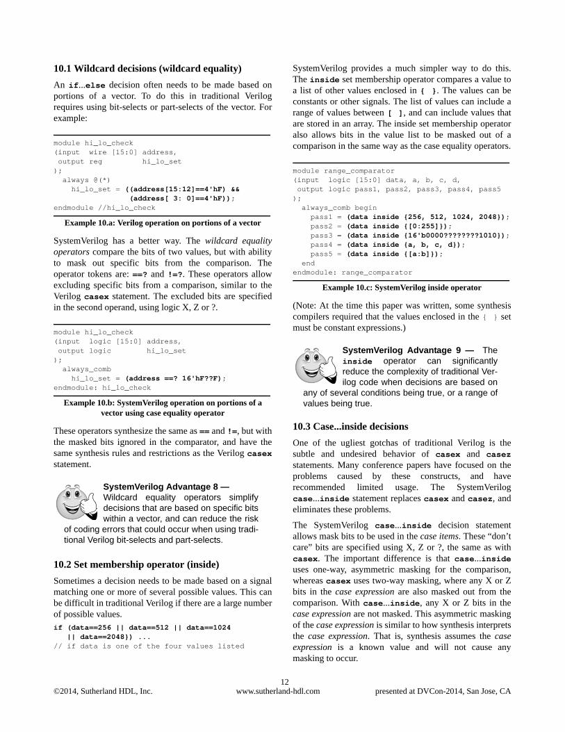
SystemVerilog provides a much simpler way to do this.The inside set membership operator compares a value toa list of other values enclosed in { }. The values can beconstants or other signals. The list of values can include arange of values between [ ], and can include values thatare stored in an array. The inside set membership operatoralso allows bits in the value list to be masked out of acomparison in the same way as the case equality operators.
module range_comparator(input logic [15:0] data, a, b, c, d, output logic pass1, pass2, pass3, pass4, pass5); always_comb begin pass1 = (data inside {256, 512, 1024, 2048}); pass2 = (data inside {[0:255]}); pass3 = (data inside {16'b0000????????1010});
pass4 = (data inside {a, b, c, d});pass5 = (data inside {[a:b]});
endendmodule: range_comparator
Example 10.c: SystemVerilog inside operator
(Note: At the time this paper was written, some synthesiscompilers required that the values enclosed in the { } setmust be constant expressions.)
10.3 Case...inside decisions
One of the ugliest gotchas of traditional Verilog is thesubtle and undesired behavior of casex and casezstatements. Many conference papers have focused on theproblems caused by these constructs, and haverecommended limited usage. The SystemVerilogcase...inside statement replaces casex and casez, andeliminates these problems.
The SystemVerilog case...inside decision statementallows mask bits to be used in the case items. These “don’tcare” bits are specified using X, Z or ?, the same as withcasex. The important difference is that case...insideuses one-way, asymmetric masking for the comparison,whereas casex uses two-way masking, where any X or Zbits in the case expression are also masked out from thecomparison. With case...inside, any X or Z bits in thecase expression are not masked. This asymmetric maskingof the case expression is similar to how synthesis interpretsthe case expression. That is, synthesis assumes the caseexpression is a known value and will not cause anymasking to occur.
SystemVerilog Advantage 8 — Wildcard equality operators simplifydecisions that are based on specific bitswithin a vector, and can reduce the risk
of coding errors that could occur when using tradi-tional Verilog bit-selects and part-selects.
SystemVerilog Advantage 9 — Theinside operator can significantlyreduce the complexity of traditional Ver-ilog code when decisions are based on
any of several conditions being true, or a range ofvalues being true.
©2014, Sutherland HDL, Inc. www.sutherland-hdl.com presented at DVCon-2014, San Jose, CA13
In the following example, any X or Z bits in opcode willnot be masked, and an invalid instruction will be trappedby the default condition:
module decoder(output logic [2:0] control, input logic [3:0] opcode); always_comb begin case (opcode) inside 4'b0???: control = 3'b000; // only test msb 4'b10??: control = 3'b001; // test hi bits 4'b1111: control = 3'b110; // test all bits default: control = 3'bxxx; endcase endendmodule: decoder
Example 10.d: case...inside decision statement with wild cards
If casex had been used in the preceding example, any bitsin opcode that were X or Z might have resulted in a branchother than the default being executed. This double-sidedmasking is different behavior than the synthesized gate-level implementation, which means the gate-levelimplementation is not what was verified at the RTL level.
10.4 Unique, unique0 and priority decision checks
From the earliest days of RTL synthesis, synthesiscompilers have used directives (also called “pragmas”) toguide the mapping of case statements to gates. Two keydirectives are full_case and parallel_case. The primaryproblem with these synthesis directives is that theyrepresent the design differently to the synthesis tool thanhow the design was simulated and verified.
These directives cause synthesis to perform specificoptimizations to the gate-level implementation of the casedecisions. A major flaw with the full_case andparallel_case synthesis directives is that the commands arehidden in comments. Simulation is not affected by thedirectives, and therefore simulation cannot verify that theoptimization effects of these directives are appropriate inthe design. That is to say, the full_case/parallel_caseoptimizations are not verified at the RTL level. There havebeen many conference papers documenting the hazards ofthe full_case and parallel_case synthesis directives (seeMills and Cummings [9], Cummings [10], Mills [12], andothers).
SystemVerilog solves this problem by bringing thefunctionality of full_case and parallel_case into the RTLmodeling world, using the keywords priority, unique0and unique as decision modifiers. In simulation, thesedecision modifiers add built-in verification checking tohelp detect when the full_case or parallel_caseoptimizations would not be desirable. This checking canhelp detect and prevent two common coding errors that canoccur with decision statements:
• A case expression value occurs that is not specified inthe case items (indicating that full_case synthesisoptimization will not work correctly).
• A case expression value occurs that matches multiplecase item branches. (indicating that parallel_casesynthesis optimization will not work correctly).
For synthesis, these modifiers enable the appropriatefull_case and/or parallel_case synthesis optimizations.Table 1 shows the mapping between the SystemVerilogdecision modifiers and the synthesis directives:
(Note: At the time this paper was written, the unique0case was not supported by some synthesis compilers).
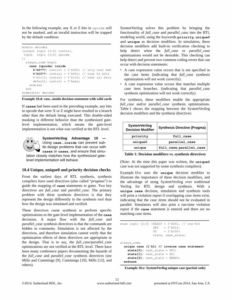
Example 10.e uses the unique decision modifier toillustrate the importance of these decision modifiers, andthe advantage of using SystemVerilog over traditionalVerilog for RTL design and synthesis. With aunique case decision, simulation and synthesis toolswill print a violation report if overlapping case items exist,indicating that the case items should not be evaluated inparallel. Simulators will also print a run-time violationreport if the case statement is entered and there are nomatching case items.
enum logic [2:0] {READY = 3'b001, // one-hot SET = 3'b010, GO = 3'b100} state, next_state;
always_comb unique case (1'b1) // inverse case statement state[0]: next_state = SET; state[1]: next_state = GO; state[2]: next_state = READY; endcase
Example 10.e: SystemVerilog unique case (partial code)
SystemVerilog Advantage 10 —Using case...inside can prevent sub-tle design problems that can occur withcasex or casez, and ensure that simu-
lation closely matches how the synthesized gate-level implementation will behave.
SystemVerilog Decision Modifier
Synthesis Directive (Pragma)
priority full_case
unique0 parallel_case
unique full_case, parallel_case
Table 1: Decision modifiers vs. synthesis directives

©2014, Sutherland HDL, Inc. www.sutherland-hdl.com presented at DVCon-2014, San Jose, CA14
The example above will print a violation report if multipleconditions match, such as if state has a value of 3'b111,or if there are no matches, such as if state has a value of3'b000. These violation reports are important! Theyindicate that state values are occurring that the gate-levelimplementation will not be decoded if the case statementis synthesized with full_case, parallel_case optimization.
Note: It is not always desirable to have the synthesis gateminimizations that can result from either the synthesisdirectives or the SystemVerilog decision modifiers. Theseoptimizations should be used with caution. Also note thatthe priority, unique0 and unique decision modifiersdo not prevent latches, and do not flag all conditions thatmight infer latches. More details on the priority,unique0 and unique decision modifiers can be found inconference papers by Cummings [10], Sutherland [11],Sutherland and Mills [14], and in Sutherland HDL trainingworkshops.
11. Streaming operators
Traditional Verilog does not have an operator that willreverse the bits or bytes of a vector. For a bit reversal,engineers might be tempted to try the following assignmentstatement, but quickly find out that this is an illegalassignment, because Verilog (and SystemVerilog) requiresthat part selects of vector use the same endian conventionas the declaration of the vector. Example 11.a is illegalbecause the part-select of data on the right-hand side of
the assignment has bit 0 as the most-significant bit, but thedeclaration of data has bit 0 as the least-significant bit.
parameter WIDTH=64;reg [WIDTH-1:0] data;
always @(posedge clock)if (swap_bits)
data[WIDTH-1:0] <= data[0:WIDTH-1]; //illegal
Example 11.a: Illegal attempt for a bit reversal
With traditional Verilog, a bit or byte reversal on a vectorwith a fixed width can be done using a concatenateoperator, as shown on the following 8-bit vector:
module swap_bits(input wire [7:0] data_in, input wire swap_bits, input wire clock, output wire [7:0] data_out); reg [7:0] d; assign data_out = d; always @(posedge clock) begin d <= data_in; if (swap_bits) d[7:0] <= { d[0],d[1],d[2],d[3],
d[4],d[5],d[6],d[7] }; endendmodule
Example 11.b: Verilog style bit reversal, fixed vector size
Using a concatenate operator is cumbersome for larger sizevectors, and impossible for vectors with a parameterizedwidth. Another solution that will work with larger vectorsizes and parameterized widths is to use a for-loop thatiterates through each bit of a vector, as in Example 11.c. Afor-loop can also be used to do a byte reversal, althoughthe code becomes more complex (obfuscated might be abetter description), as shown in the Example 11.c.
module swap_bits_or_bytes#(parameter WIDTH=64)(input wire [WIDTH-1:0] d_in, input wire swap_bits, input wire swap_bytes, input wire clock, output reg [WIDTH-1:0] d_out); integer i;
always @(posedge clock) begin d_out <= d_in; if (swap_bits) for (i=0; i<WIDTH; i=i+1) d_out[(WIDTH-1)-i] <= d_out[i]; else if (swap_bytes) for (i=0; i<WIDTH; i=i+8) d_out[((WIDTH-1)-i)-:8] <= d_out[i+:8];
SystemVerilog Advantage 11 — Thepriority, unique0 and unique deci-sion modifiers have built-in checkingthat will catch many of the potential haz-
ards when using synthesis full_case and/orparallel_case optimizations. This checking canwarn engineers when full_case or parallel_casesynthesis optimizations would not be appropriatefor the design.
SystemVerilog Advantage 12 — Thepriority, unique0 and unique deci-sion modifiers can also be used withif...else decisions. This provides the
same synthesis optimizations that could only bedone with case statements with traditional Verilog.The decision modifiers also provide simulationchecking, to help ensure the optimized if...elsedecisions will work as intended.
Question 9 — Can my synthesis compilerreverse all the bits or bytes of my parame-terized-width data word in one operation?
With SystemVerilog it can!
©2014, Sutherland HDL, Inc. www.sutherland-hdl.com presented at DVCon-2014, San Jose, CA15
endendmodule //swap_bits
Example 11.c: Verilog-style bit or byte reversal using for-loop
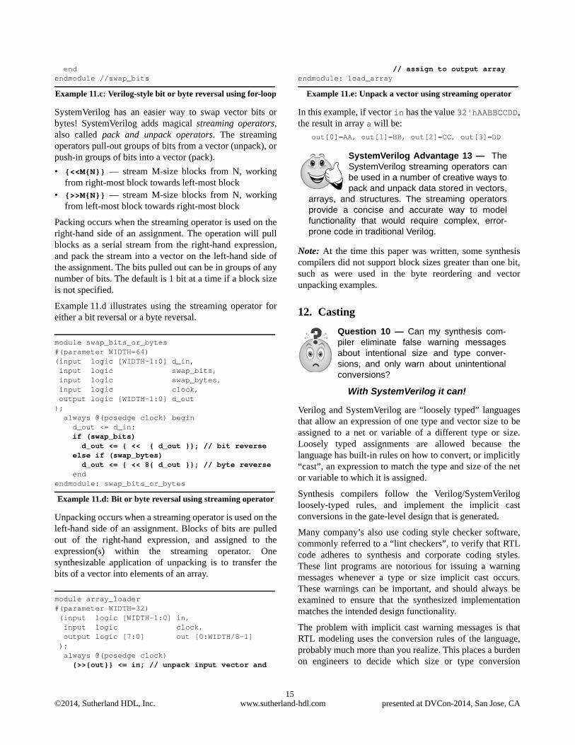
SystemVerilog has an easier way to swap vector bits orbytes! SystemVerilog adds magical streaming operators,also called pack and unpack operators. The streamingoperators pull-out groups of bits from a vector (unpack), orpush-in groups of bits into a vector (pack).
• {<<M{N}} — stream M-size blocks from N, workingfrom right-most block towards left-most block
• {>>M{N}} — stream M-size blocks from N, workingfrom left-most block towards right-most block
Packing occurs when the streaming operator is used on theright-hand side of an assignment. The operation will pullblocks as a serial stream from the right-hand expression,and pack the stream into a vector on the left-hand side ofthe assignment. The bits pulled out can be in groups of anynumber of bits. The default is 1 bit at a time if a block sizeis not specified.
Example 11.d illustrates using the streaming operator foreither a bit reversal or a byte reversal.
module swap_bits_or_bytes#(parameter WIDTH=64)(input logic [WIDTH-1:0] d_in, input logic swap_bits, input logic swap_bytes, input logic clock, output logic [WIDTH-1:0] d_out); always @(posedge clock) begin d_out <= d_in; if (swap_bits) d_out <= { << { d_out }}; // bit reverse else if (swap_bytes) d_out <= { << 8{ d_out }}; // byte reverse endendmodule: swap_bits_or_bytes
Example 11.d: Bit or byte reversal using streaming operator
Unpacking occurs when a streaming operator is used on theleft-hand side of an assignment. Blocks of bits are pulledout of the right-hand expression, and assigned to theexpression(s) within the streaming operator. Onesynthesizable application of unpacking is to transfer thebits of a vector into elements of an array.
module array_loader#(parameter WIDTH=32) (input logic [WIDTH-1:0] in, input logic clock, output logic [7:0] out [0:WIDTH/8-1] ); always @(posedge clock) {>>{out}} <= in; // unpack input vector and
// assign to output arrayendmodule: load_array
Example 11.e: Unpack a vector using streaming operator
In this example, if vector in has the value 32'hAABBCCDD,the result in array a will be:
out[0]=AA, out[1]=BB, out[2]=CC, out[3]=DD
Note: At the time this paper was written, some synthesiscompilers did not support block sizes greater than one bit,such as were used in the byte reordering and vectorunpacking examples.
12. Casting
Verilog and SystemVerilog are “loosely typed” languagesthat allow an expression of one type and vector size to beassigned to a net or variable of a different type or size.Loosely typed assignments are allowed because thelanguage has built-in rules on how to convert, or implicitly“cast”, an expression to match the type and size of the netor variable to which it is assigned.
Synthesis compilers follow the Verilog/SystemVerilogloosely-typed rules, and implement the implicit castconversions in the gate-level design that is generated.
Many company’s also use coding style checker software,commonly referred to a “lint checkers”, to verify that RTLcode adheres to synthesis and corporate coding styles.These lint programs are notorious for issuing a warningmessages whenever a type or size implicit cast occurs.These warnings can be important, and should always beexamined to ensure that the synthesized implementationmatches the intended design functionality.
The problem with implicit cast warning messages is thatRTL modeling uses the conversion rules of the language,probably much more than you realize. This places a burdenon engineers to decide which size or type conversion
SystemVerilog Advantage 13 — TheSystemVerilog streaming operators canbe used in a number of creative ways topack and unpack data stored in vectors,
arrays, and structures. The streaming operatorsprovide a concise and accurate way to modelfunctionality that would require complex, error-prone code in traditional Verilog.
Question 10 — Can my synthesis com-piler eliminate false warning messagesabout intentional size and type conver-sions, and only warn about unintentionalconversions?
With SystemVerilog it can!
©2014, Sutherland HDL, Inc. www.sutherland-hdl.com presented at DVCon-2014, San Jose, CA16
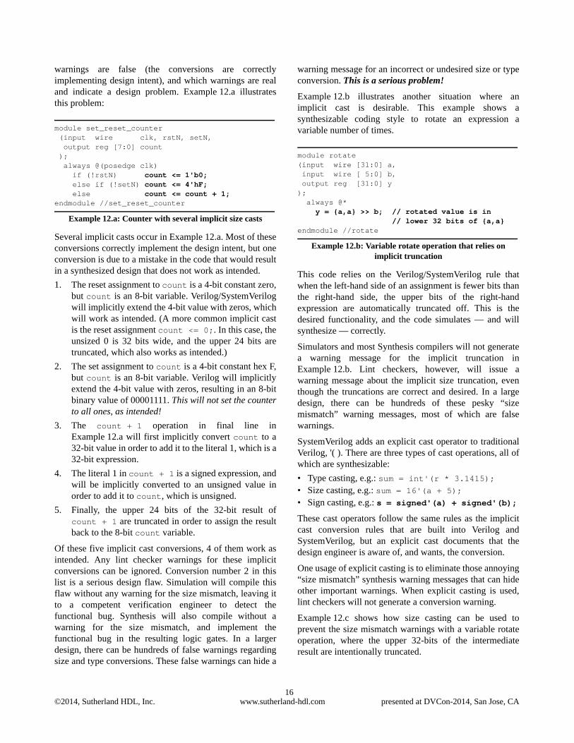
warnings are false (the conversions are correctlyimplementing design intent), and which warnings are realand indicate a design problem. Example 12.a illustratesthis problem:
module set_reset_counter (input wire clk, rstN, setN, output reg [7:0] count ); always @(posedge clk) if (!rstN) count <= 1'b0; else if (!setN) count <= 4'hF; else count <= count + 1; endmodule //set_reset_counter
Example 12.a: Counter with several implicit size casts
Several implicit casts occur in Example 12.a. Most of theseconversions correctly implement the design intent, but oneconversion is due to a mistake in the code that would resultin a synthesized design that does not work as intended.
1. The reset assignment to count is a 4-bit constant zero,but count is an 8-bit variable. Verilog/SystemVerilogwill implicitly extend the 4-bit value with zeros, whichwill work as intended. (A more common implicit castis the reset assignment count <= 0;. In this case, theunsized 0 is 32 bits wide, and the upper 24 bits aretruncated, which also works as intended.)
2. The set assignment to count is a 4-bit constant hex F,but count is an 8-bit variable. Verilog will implicitlyextend the 4-bit value with zeros, resulting in an 8-bitbinary value of 00001111. This will not set the counterto all ones, as intended!
3. The count + 1 operation in final line inExample 12.a will first implicitly convert count to a32-bit value in order to add it to the literal 1, which is a32-bit expression.
4. The literal 1 in count + 1 is a signed expression, andwill be implicitly converted to an unsigned value inorder to add it to count, which is unsigned.
5. Finally, the upper 24 bits of the 32-bit result ofcount + 1 are truncated in order to assign the resultback to the 8-bit count variable.
Of these five implicit cast conversions, 4 of them work asintended. Any lint checker warnings for these implicitconversions can be ignored. Conversion number 2 in thislist is a serious design flaw. Simulation will compile thisflaw without any warning for the size mismatch, leaving itto a competent verification engineer to detect thefunctional bug. Synthesis will also compile without awarning for the size mismatch, and implement thefunctional bug in the resulting logic gates. In a largerdesign, there can be hundreds of false warnings regardingsize and type conversions. These false warnings can hide a
warning message for an incorrect or undesired size or typeconversion. This is a serious problem!
Example 12.b illustrates another situation where animplicit cast is desirable. This example shows asynthesizable coding style to rotate an expression avariable number of times.
module rotate(input wire [31:0] a, input wire [ 5:0] b, output reg [31:0] y); always @* y = {a,a} >> b; // rotated value is in // lower 32 bits of {a,a}endmodule //rotate
Example 12.b: Variable rotate operation that relies on implicit truncation
This code relies on the Verilog/SystemVerilog rule thatwhen the left-hand side of an assignment is fewer bits thanthe right-hand side, the upper bits of the right-handexpression are automatically truncated off. This is thedesired functionality, and the code simulates — and willsynthesize — correctly.
Simulators and most Synthesis compilers will not generatea warning message for the implicit truncation inExample 12.b. Lint checkers, however, will issue awarning message about the implicit size truncation, eventhough the truncations are correct and desired. In a largedesign, there can be hundreds of these pesky “sizemismatch” warning messages, most of which are falsewarnings.
SystemVerilog adds an explicit cast operator to traditionalVerilog, '( ). There are three types of cast operations, all ofwhich are synthesizable:
• Type casting, e.g.: sum = int'(r * 3.1415); • Size casting, e.g.: sum = 16'(a + 5); • Sign casting, e.g.: s = signed'(a) + signed'(b);
These cast operators follow the same rules as the implicitcast conversion rules that are built into Verilog andSystemVerilog, but an explicit cast documents that thedesign engineer is aware of, and wants, the conversion.
One usage of explicit casting is to eliminate those annoying“size mismatch” synthesis warning messages that can hideother important warnings. When explicit casting is used,lint checkers will not generate a conversion warning.
Example 12.c shows how size casting can be used toprevent the size mismatch warnings with a variable rotateoperation, where the upper 32-bits of the intermediateresult are intentionally truncated.
©2014, Sutherland HDL, Inc. www.sutherland-hdl.com presented at DVCon-2014, San Jose, CA17
logic [31:0] a, y;logic [ 5:0] b;
always_comb y = 32'({a,a} >> b);// rotated value is in // lower 32 bits of {a,a}
Example 12.c: Variable rotate operation with casting for explicit truncation
Note that SystemVerilog also adds a $cast() dynamiccast system function for use in verification, which is notsynthesizable.
13. Tasks and functions
The traditional Verilog language has task and functionsubroutines. The primary differences between a Verilogtask and function are:
• A task can have input, output and inout arguments; afunction can only have input arguments.
• A task can have delays (execution blocks untilsimulation time advances); a function must execute inzero time.
• A task assigns results to output or inout arguments; afunction returns a result.
• A task is used like a statement in procedural code; afunction is used like an expression (the function return isthe value of the expression).
Traditional Verilog tasks and functions are synthesizable,as long as certain coding restrictions are followed.Functions have very few restrictions because they mustexecute in zero time. Tasks, on the other hand, have manyrestrictions in order to meet synthesis requirements.
These restrictions are outside the scope of this paper, butwhat is important to note is that it is a common problem towrite a task that is legal for simulation and functionallycorrect, but is illegal for synthesis. Coding errors of thisnature might not be found until after days or weeks of RTL
design, simulation and functional verification have beeninvested into a project. Restructuring the task to make itlegal for synthesis, and then re-verifying the RTLfunctionality, can add delays to a project.
SystemVerilog enhances Verilog tasks and functions inseveral ways that are synthesizable. Only two of thoseenhancements are examined in this paper: function outputarguments, and void functions.
With traditional Verilog, functions could only have inputarguments. SystemVerilog allows functions to also haveoutput and inout arguments, in the same way as tasks. Thisenhancement becomes important when coupled with asecond enhancement, void functions.
SystemVerilog adds the ability to declare a function asvoid, indicating the function does not return a value (butcan assign to output or inout arguments). A void function isused in the same way as a task, but with the requirementthat it must execute in zero time. (The function cannotcontain any construct that might stall execution untilsimulation time advances.)
Tasks have many restrictions, which can make themdifficult to synthesize. On the other hand, functions,including void functions, have very few synthesisrestrictions, and, therefore, will almost always synthesize.Void functions make it possible to write task-likesubroutines that will synthesize without the potentialproblems of tasks. Example 13.a illustrates using a voidfunction.
module ripple_adder (input logic [31:0] in1, in2, output logic [31:0] result, output logic carry);
function void ripple_add (input [31:0] a, b, output [31:0] sum, output co); logic [31:0] c; //half adder for bit zero sum[0] = a[0] ^ b[0]; c[0] = a[0] & b[0]; //full adders for remaining bits for (int i = 1; i <= 31; i++) begin sum[i] = a[i] ^ b[i] ^ c[i-1]; c[i] = (a[i] & b[i]) | (a[i] & c[i-1]) | (b[i] & c[i-1]); end co = c[31]; endfunction
always_comb ripple_add(in1, in2, result, carry); // the void function is called like a taskendmodule: ripple_adder
Example 13.a: Void function as a task-like subroutine
SystemVerilog Advantage 14 — Explicit casting eliminates false type orsize mismatch warning messages thatcan hide other important warnings.
Explicit casting also serves to document that asize, type, or signing conversion is intended.
Question 11 — Can my synthesis com-piler prevent me from writing tasks (sub-routines) that simulate, but won’tsynthesize?
With SystemVerilog it can!

©2014, Sutherland HDL, Inc. www.sutherland-hdl.com presented at DVCon-2014, San Jose, CA18
14. Interfaces
A general coding guideline in software is to usesubroutines whenever the same code is required in morethan one place, rather than duplicating that code.Unfortunately, traditional Verilog does not support thisgood coding practice when it comes to modeling thecommunication between modules. Example 14.a illustratesconnecting a master device to a slave device, and showshow traditional Verilog requires declarations to beduplicated several times.
module master(inout wire [31:0] data, output reg [ 4:0] address, output reg read, write, input wire clk, rstN);
... // master's functionality not shownendmodule //master
module slave(inout wire [31:0] data, input wire [ 4:0] address, input wire read, write, input wire clk, rstN);
... // slave's functionality not shownendmodule //slave
module top(inout wire [31:0] data, output wire [ 4:0] address, output wire read, write, input wire clock, reset); master u1 (.data (data), .address (address), .read (read), .write (write), .clk (clock), .rstN (reset) ); slave u2 (.data (data),
.address (address), .read (read), .write (write), .clk (clock), .rstN (reset) );endmodule //top
Example 14.a: Verilog style inter-module communication (lots of duplicated declarations)
In this simple example, the signals data, address, readand write that traverse between mod_a and mod_b arelisted seven times. If a design change occurs, and anadditional signal needs to be communicated between thetwo modules, or if the specification of a bus width changes,the Verilog source code will need to be modified in severaldifferent places. Typically, each module will be in adifferent file, making it difficult (and error prone) to makechanges to the communication protocol signals.
SystemVerilog provides a more abstract way for modulesto communicate, called an interface. An interface can beused to encapsulate signal declaration information in oneplace. Interfaces are an ideal RTL design construct forwhen design blocks communicate using a standard busprotocol such as AMBA AHB or USB 3.0 or an in-houseproprietary protocol.
Example 14.b uses an interface to encapsulate the signalsfrom Example 14.a into a single location. Now, if a signalneeds to be added between the two modules, or a change toa vector width is needed, only a single source code locationneeds to be modified, instead of having to modify the portlist in every module that uses the communication bus.
interface comm_bus; wire [31:0] data; logic [ 4:0] address; logic read, write;
modport m_ports (inout data, output address, read, write);
modport s_ports (inout data, input address, read, write);endinterface: comm_bus
module master(interface a1, // generic interface portinput clk, rstN
);... // master's functionality not shown
endmodule: master
module slave(comm_bus b1, // type-specific interface port input clk, rstN);
... // slaves's functionality not shownendmodule: slave
SystemVerilog Advantage 15 — Using void functions instead of tasks inRTL code can help ensure that subrou-tines will be synthesizable. Void func-
tions help prevent a common problem when usingtasks, where the model works correctly in simula-tion, but won’t synthesize.
Question 12 — Can my synthesis com-piler support modeling standard bus proto-col signals at a higher level of abstractionthat avoids code duplication?
With SystemVerilog it can!
©2014, Sutherland HDL, Inc. www.sutherland-hdl.com presented at DVCon-2014, San Jose, CA19
module top; logic clock, reset;
comm_bus i1(); // instance of the interface
master u1 (.a1 (i1.m_ports), // connect i/f .clk (clock), .rstN (reset));
slave u2 (.b1 (i1.s_ports), // connect i/f .clk (clock), .rstN (reset));endmodule: top
Example 14.b: SystemVerilog style inter-module communication using interface ports
In the master example above, interface port a1 is declaredas an interface port type, instead of the traditionalinput, output or inout port direction. This is referred toas a “generic interface port”. An instance of any interfacedefinition can be connected to a generic interface port. Inthe slave example, interface port b1 is declared as acomm_bus port type. This is referred to as a “type-specificinterface port”. It is only legal to connect an instance of acomm_bus interface to this type-specific interface port.The authors recommend only using type-specific interfaceports in design models. Designs are written to expectspecific signals within the interface port. A type-specificinterface port ensures the intended interface, with itsinternal signals, will be connected to that port.
(Note: At the time this paper was written, some synthesiscompilers did not support, or imposed restrictions, ongeneric interface ports.)
Interfaces can do more than just encapsulate the signals ofa bus protocol. Interfaces can encapsulate functionalityassociated with the signals that make up the bus. Forexample, an interface might contain a function that returnsthe parity of its data bus. Interfaces can also encapsulatebuilt-in verification code, such as assertions, so that allcommunications over the bus are automatically verified.To be synthesizable, any functional code within aninterface must adhere to synthesizable RTL coding rules.
15. Vector fill tokens
With traditional Verilog, there is no simple way to fill avector with all ones. The only options are to define a literalvalue of all ones, or to use operations such as replicate orinvert. Any of these approaches can lead to design errorswhen bus widths are parameterized to allow the width to beredefined for each usage of a model.
In Example 15.a shows a set/reset flip flop where the flipflop is set by assigning a literal value of all ones.
module set_reset_dffN#(parameter N = 64)(input wire clk, rstN, setN, input wire [N-1:0] d, output reg [N-1:0] q); always @(posedge clk) // synchronous set/reset if (!rstN) q <= 64'h0; // resets all bits to 0 else if (!setN) q <= 64'hFFFFFFFFFFFFFFF; // sets at most else // 64 bits to 1 q <= d;endmodule //set_reset_dffN
Example 15.a: Verilog style of setting a vector to all ones
Example 15.a has a serious flaw! If parameter N isredefined to something larger than 64 bits, the resetfunctionality will still be correct because of Verilogimplicit cast rules that will extend the 64-bit 0 withadditional zeros (see Section 12). The flaw is that the setfunctionality will no longer function as intended. The 64-bits of 1 will be extended with zeros, resulting in a faultydesign. Synthesis compilers will implement this faultyfunctionality in the gate-level design since that is what wasmodeled in the RTL code.
SystemVerilog adds a simple construct to specify that allbits of an expression should be set to 0, 1, X or Z. Thevector size of the literal value is automatically determined,based on its context.
• ’0 fills all bits on the left-hand side with 0• ’1 fills all bits on the left-hand side with 1• ’z fills all bits on the left-hand side with z• ’x fills all bits on the left-hand side with x
These context-dependent fill tokens will always function asintended, without the flaw that was in the previous Verilogexample. The following example illustrates using theSystemVerilog fill tokens.
SystemVerilog Advantage 16 — Interfaces simplify complex bus defini-tions and interconnections, and ensureconsistency throughout the design.
Interfaces can substantially reduce redundantdeclarations within a design, which leads to codethat is easier to maintain and easier to reuse.
Question 13 — Can my synthesis com-piler fill vectors of any size and withparameterized widths with all 1s?
With SystemVerilog it can!
©2014, Sutherland HDL, Inc. www.sutherland-hdl.com presented at DVCon-2014, San Jose, CA20
module set_reset_dffN#(parameter N = 64)(input logic clk, rstN, setN, input logic [N-1:0] d, output logic [N-1:0] q); always_ff @(posedge clk) // synch. set/reset if (!rstN) q <= '0; // reset all bits to 0 else if (!setN) q <= '1; // set all bits to 1 else q <= d;endmodule: set_reset_dffN
Example 15.b: SystemVerilog style of setting a vector to all 1
16. Expression size functions
A common situation is for the vector width of a bus to bedependent on some other declaration. For example, thewidth of FIFO read and write pointers are dependent on thedepth (number of storage locations) in the FIFO. This isillustrated in Example 16.a, which uses traditional Verilog.
module fifo#(parameter DEPTH = 32, // depth of the FIFO D_WIDTH = 8, // data bus width P_WIDTH = 5 // pointer widths) // (depend on DEPTH)(input wire i_clk, o_clk, input wire [P_WIDTH-1:0] rd_ptr, wr_ptr, input wire [D_WIDTH-1:0] data_in, output reg [D_WIDTH-1:0] data_out); reg [D_WIDTH-1:0] storage [0:DEPTH-1];
always @(posedge i_clk) storage[wr_ptr] <= data_in;
always @(posedge o_clk) data_out <= storage[rd_ptr];endmodule // fifo
Example 16.a: Verilog style port sizes with dependencies, using hard coded calculations
With traditional Verilog, the width of the read and writepointers (the P_WIDTH parameter in the precedingexample) must be calculated by the design engineer. If adifferent value for the FIFO DEPTH parameter is specifiedwhen the FIFO is synthesized, the designer must alsocalculate and specify a new value for P_WIDTH parameter.Failure to change P_WIDTH, or calculating an incorrectvalue, can result in a gate-level FIFO implementation thatdoes not work as intended.
With traditional Verilog, a constant function can be used tocalculate parameter values and vector widths, instead ofhard coding in the value or width, as was done inExample 16.a. Note, though, that each module that needsthis function must contain a local copy of the function,since traditional Verilog does not have packages for shareddefinitions, as discussed in Section 9. Example 16.billustrates using a constant function to calculate the size ofthe read and write pointers, based on the depth of the FIFO.
module fifo#(parameter DEPTH = 32, // depth of the FIFO D_WIDTH = 8, // data bus width P_WIDTH = log2(DEPTH) // ptr widths)(input wire i_clk, o_clk, input wire [P_WIDTH-1:0] rd_ptr, wr_ptr, input wire [D_WIDTH-1:0] data_in, output reg [D_WIDTH-1:0] data_out); reg [D_WIDTH-1:0] storage [0:DEPTH-1];
always @(posedge i_clk) storage[wr_ptr] <= data_in;
always @(posedge o_clk) data_out <= storage[rd_ptr];
function integer log2 (input DEPTH); case (DEPTH) 4: log2 = 2; 8: log2 = 3; 16: log2 = 4; 32: log2 = 5; 64: log2 = 6; 128: log2 = 7; 256: log2 = 8; default: begin $display("ERROR: Unsupported DEPTH"); $finish; // abort simulation log2 = 5; // default for synthesis end endcase endfunctionendmodule // fifo
Example 16.b: Verilog style port sizes with dependencies, using a constant function
SystemVerilog provides two special system functions thatcan be useful in synthesizable RTL code, $bits and
SystemVerilog Advantage 17 — Vector fill values simplify code, and helpensure the code will function correctlyThese fill tokens can also prevent size
mismatches between the fill value and assignmentor expression in which the value is used.
Question 14 — Can my synthesis com-piler automatically calculate the size of myaddress bus, based on the depth of mymemory storage?
With SystemVerilog it can!

©2014, Sutherland HDL, Inc. www.sutherland-hdl.com presented at DVCon-2014, San Jose, CA21
$clog2. These functions can help prevent errors indeclaration sizes, and help with writing models that arescalable and reusable as specifications change in current orfuture projects.
The $bits system function returns the number of bitscomprised in a net or variable name, or an expression. Thebasic usage is:
• $bits(data_type) • $bits(expression)
where: data_type can be any built-in data type oruser-defined type; expression can be any value,including or unpacked arrays and operation results.
For synthesis, $bits can be used in port declarations, netand variable declarations, and constant definitions.
The $clog2 function returns the ceiling of the log base 2(the log2 rounded up to an integer value) of a vector. Thefunction can be used in RTL models to declare vector sizesbased on the value of a parameter or localparamconstant, or the return of $bits. Example 16.c shows howthe traditional Verilog FIFO in Example 16.a can bewritten in synthesizable SystemVerilog so that P_WIDTH isautomatically calculated from the value of DEPTH. IfDEPTH is redefined, P_WIDTH will automatically scale tothe correct width. The risk of inadvertently specifying anincorrect value for P_WIDTH has been eliminated.
module fifo#(DEPTH = 32, // depth of the FIFO D_WIDTH = 8, // data bus width P_WIDTH = $clog2(DEPTH) // pointer widths)(input logic i_clk, o_clk, input logic [P_WIDTH-1:0] rd_ptr, wr_ptr, input logic [D_WIDTH-1:0] data_in, output logic [D_WIDTH-1:0] data_out); logic [D_WIDTH-1:0] storage [0:DEPTH-1];
always_ff @(posedge i_clk) storage[wr_ptr] <= data_in;
always_ff @(posedge o_clk) data_out <= storage[rd_ptr];endmodule: fifo
Example 16.c: SystemVerilog style port sizes with dependencies
The following Example 16.d shows a more elaborate usageof $bits and $clog2. This example concisely models aconfigurable packet register, where each packet contains apayload that is an array of data words. The payload arraysize is parameterized, and can be specified as a differentsize for each usage of the register. The register storage is avector, where the size of the vector is based on the size ofthe array. The model uses the SystemVerilog streaming
operator to transfer the array contents into the register (seeSection 11). All declarations in this model willautomatically scale to the correct widths to match thepayload size. This concise model represents a significantnumber of logic gates, once synthesized.
package payload_64; localparam MAX_PAYLOAD = 64;
typedef struct { logic [63:0] start_address; logic [$clog2(MAX_PAYLOAD)-1:0] xfer_size; logic [ 7:0] payload [0:MAX_PAYLOAD-1]; } packet_t;endpackage: payload_64
module payload_register(input logic clk, input payload_64::packet_t in, output logic [$bits(in.payload)-1:0] out); always_ff @(posedge clk) out <= { << { in.payload }}; // pack entire // payload array // into registerendmodule: payload_register
Example 16.d: Using SystemVerilog $bits and $clog2
17. Synthesis compiler support for System-VerilogThe SystemVerilog constructs discussed in this paper aresupported by most major ASIC and FPGA synthesiscompilers. There are exceptions, however, where specificconstructs are not supported, or are only partiallysupported, by specific synthesis compilers. Appendix Acontains a table showing the synthesis compiler support forthe constructs shown in this paper.
18. Additional synthesizable SystemVerilog constructsThere are many more RTL modeling constructs thatSystemVerilog adds to traditional Verilog, and which aresynthesizable by most major RTL synthesis compilers.These constructs include:
• 2-state types• Parameterized types• $unit declaration space
SystemVerilog Advantage 18 — The$bits and $clog2 expression sizefunctions enable writing RTL modelsthat are scalable and “correct by con-
struction”. They eliminate the risk of an engineerinadvertently specifying incongruent vector widths.

©2014, Sutherland HDL, Inc. www.sutherland-hdl.com presented at DVCon-2014, San Jose, CA22
• Unions• ++ and -- increment/decrement operators• Multiple for-loop iterator variables• do...while loops• foreach loops• break and continue loop controls• Continuous assignments to variables• Task/function formal arguments with default values• Task/function calls with pass by name• Function return statements• Parameterized tasks and functions• Dot-name and dot-star netlist connections• Named statement group ends• Version keyword compatibility directives• const variables• Assertions• Local time unit and precision definitions
These additional constructs are not covered in this paper,but are discussed in another paper by the authors (seeSutherland and Mills [14]). Note that some of theseconstructs might not be supported in some synthesiscompilers.
19. SummarySystemVerilog is synthesizable! When the IEEE extendedthe Verilog-2001 standard, one of the primary goals was tomake it possible for design engineers to:
• Be more productive by being able to model morefunctionality with fewer lines of code. Many of theSystemVerilog constructs that have been discussed inthis paper achieve that goal. Structures, user-definedtypes, array assignments and interfaces are examples ofhow SystemVerilog can significantly reduce the amountof code needed to represent complex functionality.
• Clearly indicate design intent. Specialized proceduralblocks and decision modifiers allow engineers to stateintention. Software tools can then verify whether thatintent is correctly represented in the RTL code.
• More accurately align simulation behavior to the waysynthesis tools realize that functionality in gates.Constructs such as enumerated types, case...insideand the priority, unique0 and unique ensure thatRTL simulation and gate-level implementation closelycorrespond.
• Enable design reuse through scalable, configurablemodels. SystemVerilog constructs like interfaces, arrayassignments, context-aware literal values and manyother SystemVerilog features help to achieve this goal.
These benefits of SystemVerilog enable design engineersto rapidly develop RTL code, more easily maintain that
code, and minimize the classic Verilog gotchas, where theRTL code simulates differently than the synthesized gate-level design.
This paper has shown a number of advantages fordesigning with, and synthesizing, SystemVerilog. Theseadvantages show that there are substantial benefits to begained from using SystemVerilog instead of traditionalVerilog for RTL design and synthesis. The advantagesmentioned in the paper are:
2. You no longer need to worry about when to declaremodule ports or local signals as wire or reg. WithSystemVerilog, you can declare all module ports andlocal signals as logic, and software tools willcorrectly infer nets or variables for you.
3. Designs that frequently manipulate parts of a vector aresimpler to model, more self-documenting, and correctby construction.
5. Array copy assignments can significantly reduce thecomplexity of design code for moving blocks of datafrom one array to another. Array assignments also donot require changing any code if the sizes of the arrayschange.
4. Enumerated types can prevent coding errors that couldbe difficult to detect and debug!
6. By using structures to bundle related signals together,the signals can be assigned and transferred to othermodules as a bundle, reducing the lines of code andensuring consistency.
7. Packages provide a clean and simple way to usedefinitions of tasks, functions, and user-defined typesthroughout a design and verification project. Packagescan eliminate duplicate code, the risk of mismatches indifferent blocks of a design, and the difficulties ofmaintaining duplicate code.
1. The benefits of using the SystemVerilogalways_comb, always_latch and always_ffprocedural blocks are huge! They can prevent seriousmodeling errors, and they enable software tools toverify that design intent has been met.
8. Wildcard equality operators simplify decisions that arebased on specific bits within a vector, and can reducethe risk of coding errors that could occur when usingtraditional Verilog bit-selects and part-selects.
9. The inside operator can significantly reduce thecomplexity of traditional Verilog code when decisionsare based on any of several conditions being true, or arange of values being true.
10. Using case...inside can prevent subtle designproblems that can occur with casex or casez, andensure that simulation closely matches how thesynthesized gate-level implementation will behave.
©2014, Sutherland HDL, Inc. www.sutherland-hdl.com presented at DVCon-2014, San Jose, CA23
11. The priority, unique0 and unique decisionmodifiers have built-in checking that will catch manyof the potential hazards when using synthesis full_caseand/or parallel_case optimizations. This checking canwarn engineers when full_case or parallel_casesynthesis optimizations would not be appropriate forthe design.
12. The priority, unique0 and unique decisionmodifiers can also be used with if...else decisions.This provides the same synthesis optimizations thatcould only be done with case statements withtraditional Verilog. The decision modifiers alsoprovide simulation checking, to help ensure theoptimized if...else decisions will work as intended.
13. The SystemVerilog streaming operators can be used ina number of creative ways to pack and unpack datastored in vectors, arrays, and structures. The streamingoperators provide a concise and accurate way to modelfunctionality that would require complex, error-pronecode in traditional Verilog.
14. Explicit casting eliminates false type or size mismatchwarning messages that can hide other importantwarnings. Explicit casting also serves to document thata size, type, or signing conversion is intended.
15. Using void functions instead of tasks in RTL code canhelp ensure that subroutines will be synthesizable.Void functions help prevent a common problem whenusing tasks, where the model works correctly insimulation, but won’t synthesize.
16. Interfaces simplify complex bus definitions andinterconnections, and ensure consistency throughoutthe design. Interfaces can substantially reduceredundant declarations within a design, which leads tocode that is easier to maintain and easier to reuse.
17. Vector fill values simplify code, and help ensure thecode will function correctly These fill tokens can alsoprevent size mismatches between the fill value andassignment or expression in which the value is used.
18. The $bits and $clog2 expression size functionsenable writing RTL models that are scalable and“correct by construction”. They eliminate the risk of anengineer inadvertently specifying incongruent vectorwidths.
20. Conclusion Appendix A says it all. This appendix shows how well sixdifferent synthesis compilers support the SystemVerilogconstructs illustrated in the examples listed in this paper.The nearly full support from six different synthesiscompilers for these examples is proof that engineers canand should take advantage of the many benefits availablefrom using SystemVerilog in ASIC and FPGA designs!
21. AcknowledgementsThe authors express their appreciation to ShalomBresticker of the DVCon Technical Committee for hisdetailed review of the initial draft of this paper, andsuggestions for improving the quality of the paper.
22. References[1] “1364-2001 IEEE Standard for Verilog Hardware Descrip-
tion Language”, IEEE, Pascataway, New Jersey. Copyright2001. ISBN: 0-7381-2826-0.
[2] “1800-2012 IEEE Standard for System Verilog: UnifiedHardware Design, Specification and Verification Language”,IEEE, Pascataway, New Jersey. Copyright 2013. ISBN: 978-0-7381-8110-3 (PDF), 978-0-7381-8111-0 (print).
[3] “HDL Compiler™ for SystemVerilog User Guide, Version G-2012.06-SP4”, Synopsys, December 2012, https://solvnet.synopsys.com.
[4] “Synopsys FPGA Synthesis Reference Manual”, Synopsys,December 2012, https://solvnet.synopsys.com.
[5] “Synopsys FPGA Synthesis User Guide”, Synopsys, Decem-ber 2012, https://solvnet.synopsys.com.
[6] Sutherland, Davidmann and Flake, “SystemVerilog forDesign Engineers, second edition”, Springer, Boston, Massa-chusetts. Copyright 2006. ISBN: 978-0-387-36495-7.
[7] “The Benefits of SystemVerilog for ASIC Design and Verifica-tion, Version 2.5”, Synopsys, January 2007, https://solvnet.synopsys.com.
[8] Pieper, “SystemVerilog from a Synthesis Perspective”,Design and Verification Conference (DVCon), San Jose, Cal-ifornia, March 2004.
[9] Mills and Cummings, “RTL Coding Styles That Yield Simula-tion and Synthesis Mismatches”, Synopsys Users Group(SNUG) conference, San Jose, California, March 1999.
[10]Cummings, “ ‘full_case parallel_case’, the Evil Twins of Ver-ilog Synthesis”, Synopsys Users Group (SNUG) conference,Boston, Massachusetts, 1999.
[11]Sutherland, “SystemVerilog Saves the Day—the Evil Twinsare Defeated! unique and priority” are the new Heroes”,Synopsys Users Group (SNUG) conference, San Jose, Cali-fornia, March 2005.
[12]Mills, “Yet Another Latch and Gotchas Paper”, SynopsysUsers Group (SNUG) conference, San Jose, California,March 2012.
[13]Sutherland, “I’m Still in Love with My X!”, Design and Veri-fication Conference (DVCon), San Jose, California, February2013.
[14]Sutherland and Mills, “Synthesizing SystemVerilog: Bustingthe Myth that SystemVerilog is only for Verification”, Synop-sys Users Group (SNUG) Silicon Valley conference, SantaClara, California, March 2013.

©2014, Sutherland HDL, Inc. www.sutherland-hdl.com presented at DVCon-2014, San Jose, CA
24
Appendix A: Table of synthesis compiler support
The following table lists the SystemVerilog constructs discussed in this paper, and shows the support for these constructs byseveral major synthesis compilers. The information in this table is based the most current released versions available to theauthors at the time this paper was written.
NOTE: The support for SystemVerilog constructs is based solely on the examples listed in this paper. These examples arenot exhaustive and do not test every aspect of each SystemVerilog construct. The authors feel, however, that the examplesshow proper and common usage for these constructs. The nearly full support from six different synthesis compilers for theexamples in this paper proves that engineers can and should take advantage of the many benefits available from usingSystemVerilog in ASIC and FPGA designs.
*partial indicates that a compiler either: a) accepted some of the constructs listed in the table row, but not all of theconstructs, or b) accepted a construct in the paper example but did not produce the correct results (e.g.: some compilersparsed always_comb and always_ff, but did not generate warnings for some of the incorrect logic within those blocks).
The synthesis compiler used to test the examples in this paper are (in a different order than the table): Synopsys DesignCompiler (also called DC and HDL Compiler) version 2013.03-SP4, Synopsys Synplify-Pro version 2013.03-SP1, MentorPrecision Synthesis RTL Plus version 2013a.9, Cadence Encounter RTL Compiler version 13.10, Xilinx Vivado free webversion 13.4, and Altera Quartus II free web version 13.1.
SystemVerilog ConstructSynthesisCompiler
A
SynthesisCompiler
B
SynthesisCompiler
C
SynthesisCompiler
D
SynthesisCompiler
E
SynthesisCompiler
F
always_ff, always_comb, always_latch yes yes yes yes partial* partial*
logic type / inferred wire or reg partial* yes yes yes yes yes
Vectors with subfields yes yes yes yes yes yes
Enumerated types yes yes yes yes yes yes
Array assignments and copying, array ports yes partial* yes yes yes yes
Structures and structure assignments yes yes yes yes yes yes
Packages and package import yes yes yes partial* yes yes
==? wildcard equality operator yes yes yes yes yes yes
inside operator, constant expressions yes yes yes yes yes no
inside operator, variable expressions no no yes yes yes no
case…inside decisions yes yes yes yes yes no
unique and priority decisions yes yes yes yes yes yes
unique0 decisions partial* no yes no no no
Streaming operators (pack and unpack) yes yes yes yes yes no
Casting yes yes yes yes yes yes
Void functions yes yes yes yes yes yes
Interfaces partial* yes yes yes yes yes
Vector fill tokens yes yes yes yes yes yes
$bits, $clog2 expression size function yes yes yes yes yes yes