can router can repeater system description -...
TRANSCRIPT

CAN RouterCAN RepeaterSystem Description
1st Edition
This publication is not subject to change procedures.New versions can be found in INFORM underwww.wabco-auto.com
© Copyright WABCO 2010
Vehicle Control Systems
Changes are subject to change without noticeVersion 001/05.10
815 010 176 3

2
CAN RouterCAN Repeater
Table of contents
1 Safety information . . . . . . . . . . . . . . . . . . . . . . . . . 3
1.1 Avoiding electro-static charge and uncontrolled discharging (ESD) . . . . . . . . . . . . . . . . . . . . . 4
2 System . . . . . . . . . . . . . . . . . . . . . . . . . . . . . . . . . . 5
2.1 CAN Router . . . . . . . . . . . . . . . . . . . . . . . . . . 5
2.2 CAN Repeater . . . . . . . . . . . . . . . . . . . . . . . . 6
2.3 System prerequisites, Configuration . . . . . . . 6
2.4 Certificates . . . . . . . . . . . . . . . . . . . . . . . . . . . 7
3 Components . . . . . . . . . . . . . . . . . . . . . . . . . . . . . . 8
3.1 CAN Router . . . . . . . . . . . . . . . . . . . . . . . . . . 8
3.1.1 Variants of the CAN router. . . . . . . . . . 9
3.2 CAN Repeater . . . . . . . . . . . . . . . . . . . . . . . . 9
3.2.1 Variants of the CAN repeater. . . . . . . 10
3.3 Pin assignments. . . . . . . . . . . . . . . . . . . . . . 10
3.4 Pressure sensor 441 044 101 0 / 102 0. . . . 10
3.5 Cable . . . . . . . . . . . . . . . . . . . . . . . . . . . . . . 11
3.5.1 Power supply cable . . . . . . . . . . . . . . 11
3.5.2 Sensor cable . . . . . . . . . . . . . . . . . . . 12
4 Workshop instructions . . . . . . . . . . . . . . . . . . . . 13
4.1 Mounting and Installation . . . . . . . . . . . . . . . 13
4.1.1 Installation concept . . . . . . . . . . . . . . 13
4.1.2 Mounting the CAN Router / Repeater 14
4.1.3 Mounting the cable . . . . . . . . . . . . . . 15
4.1.4 Functional test . . . . . . . . . . . . . . . . . . 15
4.2 Fuses . . . . . . . . . . . . . . . . . . . . . . . . . . . . . . 15
5 Diagnostics. . . . . . . . . . . . . . . . . . . . . . . . . . . . . . 17
5.1 Diagnostic port . . . . . . . . . . . . . . . . . . . . . . . 17
5.1.1 ISO7638 towing vehicle/trailerinterface . . . . . . . . . . . . . . . . . . . . . . . 17
5.2 Hardware . . . . . . . . . . . . . . . . . . . . . . . . . . . 17
5.3 Diagnostic Software . . . . . . . . . . . . . . . . . . . 18
5.3.1 Diagnostic Software "Trailer CAN Router-Repeater". . . . . . . . . . . . . . . . 18
6 Appendix. . . . . . . . . . . . . . . . . . . . . . . . . . . . . . . . 20
6.1 Diagnostic messages. . . . . . . . . . . . . . . . . . 20
6.2 Drilling template . . . . . . . . . . . . . . . . . . . . . . 22
6.3 Diagram . . . . . . . . . . . . . . . . . . . . . . . . . . . . 23
6.3.1 CAN Router . . . . . . . . . . . . . . . . . . . . 24
6.3.2 CAN Repeater . . . . . . . . . . . . . . . . . . 27
1

3
1CAN RouterCAN Repeater
Safety information
1 Safety informationThis document describes the system structure, functions and components of theCAN Router and CAN Repeater.
Read this publication thoroughly. Adhere to all instructions, information and safetyinformation to prevent injury to persons and damage to property.
WABCO will only guarantee the security, reliability and performance of their productsand systems if all information in this publication is adhered to.
• Only trained and qualified technicians are to perform any work on the vehicle.
• Make sure to follow the specifications and instructions of the vehicle manufacturer.
• Maintain all accident regulations of the business as well as regional and nationalregulations.
• Wear suitable protective clothing when necessary.
• Your workspace must be dry as well as sufficiently illuminated and ventilated.
Risk of injury! Pedal actuations can lead to severe injuries if persons are in the vicinity of thevehicle.
Make sure that pedals cannot be actuated as follows:
– Switch the transmission to "neutral" and actuate the hand brake.
– Secure the vehicle against rolling with chocks.
– Fasten a visible note to the steering wheel indicating the work is being performedon the vehicle and that the pedals are not to be actuated.
– Do not wear a tie, loose clothing, open hair, arm bands, etc. when working on thevehicle, especially with the engine running. Keep your hands and hair away fromthe moving parts.
Fire hazard! – Use only ground lights.
– Keep flammable material (cloths, paper, etc.) away from the exhaust system.
– Do not smoke in the workplace.
– Check electrical lines for proper insulation and fastening.

4
1 CAN RouterCAN Repeater
Safety information
1.1 Avoiding electro-static charge and uncontrolled discharging (ESD)
Note during
construction and
building the vehicle:
– Prevent potential differences between components (e. g. axles) and the vehicleframe (Chassis).
Make sure that the resistance between metallic parts of the components to thevehicle frame is lower than 10 Ohm (< 10 Ohm).
Connect moving or insulated vehicle parts such as axles electrically conductivewith the frame.
– Prevent potential differences between the towing vehicle and the trailer.
Make sure that an electrically conductive connection is made via the coupling(king pin, fifth wheel, claws with pins), even with no cable connection.
– Use electrically conductive bolted connections when fastening the ECUs to thevehicle frame.
– Use only cable conforming to WABCO specifications or WABCO original cable.
– Run the cable in metallic casing if at all possible (e. g. inside the U-beam) orbehind metallic and grounded protective plating, to minimize the influence ofelectro-magnetic fields.
– Avoid the use of plastic materials if they can cause electrostatic charging.
Note during repair and
welding work on the
vehicle:
– Disconnect the battery - if installed in the vehicle.
– Disconnect cable connections to devices and components and protect the plug-ins and connections from contamination and humidity.
– Always connect the grounding electrode directly with the metal next to the weld-ing position when welding, to prevent magnetic fields and current flow via thecable or components.
Make sure that current is well conducted by removing paint or rust.
– Prevent heat influences on devices and cabling when welding.

5
2CAN RouterCAN Repeater
System
2 System
2.1 CAN Router
With special vehicle concepts such as e.g. Eurocombis or Roadtrains, the utilisationof multiple Trailer EBS systems on different axle units or trailer modules is required.
To supply the brake modulators with CAN signals in accordance with ISO 11992 andsupply voltage, an additional device is required. WABCO provides a solution in theCAN Router, with which up to four CAN routers in series can supply up to five TrailerEBS modulators.
The CAN brake signal of the towing vehicle is received by the CAN Router anddistributed to the Trailer EBS modulators.
Fig. Using a CAN router (1) in a "Eurocombi" tractor-trailer combination with two Trailer EBS
modulators (2)
CAN router with
pressure sensor
If the CAN signal of the towing vehicle is not available, a pressure sensor that can beconnected as an option generates the control pressure for the yellow hose couplingas a CAN signal and sends it through the CAN router to the Trailer EBS E1 modulatorconnected to the "Power OUT1" output to optimise timing.
Fig. Using a CAN router (1) with optional external pressure sensor (3) in a Flat Bed Trailer
with two Trailer EBS E1 modulators (2)
1 2 2
1 22
3

6
2 CAN RouterCAN Repeater
System
2.2 CAN Repeater
The CAN repeater is designed for the CAN signal transfer in overlength vehicles,such as telescoping trailers. Its task is to amplify the CAN signal to ensure the supplyfor the connected Trailer EBS over greater distances.
This is required technically as well as for legal reasons, since based on ECE R 13,the CAN line in the trailer vehicle is only allowed to be a maximum of 18 m on trailervehicles without using a CAN repeater. With a CAN repeater connected, the cablelength can be extended by up to 80 meters after the CAN repeater.
The CAN repeater is equipped with a connection for an external pressure sensor.This pressure sensor generates the brake pressure set value as a CAN signal andsends it to the downstream Trailer EBS E1 modulator to guarantee the requiredtiming in accordance with ECE R 13.
This way, the trailer can be used with towing vehicles with no CAN brake signallingas well.
Fig. Operation of a CAN repeater (1) with optional external pressure sensor (3) in an
overlength trailer with Trailer EBS E1 (2)
2.3 System prerequisites, Configuration
The CAN router / -repeater is used with the WABCO electronic braking system (T-EBS) of generations E and D.
Using trailers with CAN routers/-repeaters is permitted on towing vehicles with CANinterfaces, with at least a pneumatic control line.
On trailers with Trailer EBS E1, an external pressure sensor can be connected to theCAN router/-repeater. This pressure sensor generates the brake pressure set valueas a CAN signal to optimise the timing in accordance with ECE R 13 behind thetowing vehicle without CAN brake signalling.
! The use of the external pressure sensor with CAN router/-repeater is only possible in combination with Trailer EBS E1 (software version as of TE001418).
Trailers with 2× trailer
EBS E1
The CAN brake signal of the towing vehicle is received by the CAN Router anddistributed to both T-EBS E1 modulators. If the CAN signal is not available from thetowing vehicle, the front T-EBS E1 modulator brakes via the yellow control line whilethe rear T-EBS E1 modulator brakes via the CAN signal, which the external pressuregenerates.
Overlength trailers The CAN repeater amplifies the CAN signal for overlength trailers. If T-EBS E1 isinstalled, the same external pressure sensor is used for optimising the timing whenthere is no CAN signal from the towing vehicle.
The CAN router/-repeater in
• EuroCombis or Roadtrains,
1 2
3

7
2CAN RouterCAN Repeater
System
• Trailers with two modulators T-EBS E0 / D,
• Overlength trailers with T-EBS E0 / D
only functions if the towing vehicle is equipped with CAN.
CAN router/-repeater in combination with WABCO Trailer EBS
2.4 Certificates
Certificates for CAN router and CAN repeater
– Open the WABCO website www.wabco-auto.com
– Click on the INFORM product catalogue in the quick-access area and then onIndex
– Enter the words CAN router or CAN repeater in the search field.
CAN Router Using the CAN router in vehicle combinations with a trailer and more than one TrailerEBS E1 modulator is approved with the TÜV certificate EB124.5E (with KBArelease).
To use the CAN router in vehicle combinations with multiple trailers, there is nocertificate based on ECE R 13. WABCO does provide the TÜV certificateEB124_CanRou_0E however (no KBA release) indicating the full functionality of theunit. This informal certificate serves as proof for individual acceptance, that allrespective requirements of the towing vehicle (disconnected supply line to secondtrailer, etc.) are met by the system.
! When using the CAN router for vehicle combinations with more than one trailer, an individual acceptance must be performed for the vehicle.
CAN Repeater For using the CAN repeater in combination with the T-EBS E modulator, thecertificate EB124.5E conforming to ECE R 13 is available.
Type Trailer Trailer EBSVariants CAN
router/-repeater
Connection
external pressure
sensor
Connecting a CAN
router/-repeater
EuroCombi orRoadtrain
T-EBS E1T-EBS E0T-EBS D
CAN Router446 122 050 / 052 0
–
1st Trailer on connection Power OUT1,2nd Trailer on connection Power OUT2
Trailer vehicle with 2× T-EBS (e.g. Flat Bed Trailer)
T-EBS E1 CAN Router446 122 054 0
on CAN router Rear T-EBS modulator on connection Power OUT1,Front T-EBS modulator on connection Power OUT2
T-EBS E0T-EBS D
CAN Router446 122 054 0
on T-EBS modulator
Overlength trailer (e.g. timber trailers)
T-EBS E1 CAN Repeater446 122 051 / 053 0
on CAN Repeater T-EBS modulator on connection Power OUT1
T-EBS E0T-EBS D
CAN Repeater446 122 051 / 053 0
on T-EBS modulator

8
3 CAN RouterCAN Repeater
Components
3 Components
3.1 CAN Router
The CAN router (446 122 050 0 / 052 0) mainly consists of the ECU and threeconnecting cables (Z, X1, X2) with 7-pin DIN bayonet plugs. With version 446 122054 0, there is another connecting cable (Y) to an external nominal pressure sensor.
Electrical connections To identify the connections, the connection designations are shown on a sticker onthe housing cover and on small tags on the connectors.
Z
X1
X2
Y
Pos.Connection
designationFunction Connection cable
Z Power IN Power supply (ISO 7638) from tow vehicle
449 133 … 0 / 449 135 … 0 (for semitrailer)449 231 … 0 / 449 233 … 0 (for drawbar trailer)
X1 Power OUT1 Connection T-EBS modulator 449 347 … 0 (for T-EBS E)449 333 … 0 (for T-EBS D)X2 Power OUT2 Connection T-EBS modulator
Connection for next trailer 449 135 … 0
Y Pressure sensor
Connection of the external nominal pressure sensor (only as of T-EBS E1)
449 425 … 0

9
3CAN RouterCAN Repeater
Components
3.1.1 Variants of the CAN router
3.2 CAN Repeater
The CAN repeater (446 122 051 0 / 053 0) mainly consists of the ECU with twoconnecting cables (Z, X1) with 7-pin DIN bayonet plug-in connectors and theconnecting cable (Y) for the external nominal pressure sensor.
Electrical connections To identify the connections, the connection designations are shown on a sticker onthe housing cover and on small tags on the connectors.
WABCO number Housing symbol
Electrical connections (DIN bayonet)
Z - Power INX1 - Power OUT1
X2 - Power OUT2Y - Pressure sensor
446 122 050 0 Socket Connector –
446 122 052 0 Connector Connector –
446 122 054 0 Connector Connector Socket
X1
Z
Y
Pos.Connection
designationFunction Connection cable
Z Power IN Power supply (ISO 7638) from tow vehicle
449 133 … 0 / 449 135 … 0 (for semitrailer)449 231 … 0 / 449 233 … 0 (for drawbar trailer)
X1 Power OUT1 Connection T-EBS modulator 449 347 … 0 (for T-EBS E)449 333 … 0 (for T-EBS D)
Y Pressure sensor
Connection of the external nominal pressure sensor (only as of T-EBS E1)
449 425 … 0

10
3 CAN RouterCAN Repeater
Components
3.2.1 Variants of the CAN repeater
3.3 Pin assignments
3.4 Pressure sensor 441 044 101 0 / 102 0
The pressure sensor generates the nominal brake pressure value as a CAN signalon towing vehicles with no CAN line or on overlength trailers in order to meet thenecessary timing requirements in accordance with ECE R 13.
In connection with the Trailer EBS E1, the external pressure sensor is connected tothe yellow hose fitting and to connection Y "Pressure sensor" of the CAN router/-repeater. With a Trailer EBS of the D generation, the pressure sensor is connectedto the "IN/OUT 2" connector of the T-EBS modulator.
! As of version 1.5 of the Trailer EBS E (production date from CW 49/2009), in the diagnostic software "Trailer EBS E" with connected external pressure sensor on the CAN router/-repeater, select setting: "Nominal pressure sensor on R/R" to improve the communication between the devices.
WABCO number Housing symbolElectrical connections (DIN bayonet)
Z - Power IN X1 - Power OUT1 Y - Pressure sensor
446 122 051 0 Socket Connector Socket
446 122 053 0 Connector Connector Socket
Pos.Connection
designationConnector PIN Application
Z Power IN 1 CAN Low
2 CAN High
3 WALA
4 GND (Term. 15)
5 GND
6 Pin 15
7 Pin 30
X1 / X2 Power OUT1 / Power OUT2
1 CAN Low
2 CAN High
3 WALA
4 GND (Term. 15)
5 GND
6 Pin 15
7 Pin 30
Y Pressure sensor1 Sensor SUPPLY
2 GND
3 Sensor IN

11
3CAN RouterCAN Repeater
Components
3.5 Cable
Fig. Cabling a CAN router (1) in a "Eurocombi" tractor-trailer combination with two Trailer EBS modulators (2)
Fig. Cabling a CAN router (1) with optional external pressure sensor (3) in a Flat Bed Trailer with two Trailer EBS E1
modulators (2)
3.5.1 Power supply cable
Pos. Component Pos. Cable family
1 CAN Router 4449 133 … 0 / 449 135 … 0 (for semitrailer)449 231 … 0 / 449 233 … 0 (for drawbar trailer)
2 Trailer EBS E Modulator 5449 135 … 0449 231 … 0
3 Pressure sensor 6449 347 … 0 (for T-EBS E)449 333 … 0 (for T-EBS D)
7 449 425 … 0
8
449 173 … 0 (for semitrailers with T-EBS E)449 273 … 0 (for drawbar trailers with T-EBS E)449 172 … 0 (for semitrailers with T-EBS D)449 272 … 0 (for drawbar trailers with T-EBS D)
Cable WABCO no. L in m Cable ends - Design
Power IN semitrailer (permitted total length max. 18 m)
449 133 003 0 0,3
SocketISO 7638
ConnectorDIN bayonet
7-pin
449 133 030 0 3,0
449 133 120 0 12,0
449 133 150 0 15,0
1 2 24 6
5 8
1
2
2
3
4
67 6
1

12
3 CAN RouterCAN Repeater
Components
3.5.2 Sensor cable
Power IN semitrailer (permitted total length max. 18 m)Power OUT2 (permitted total length max. 15 m)
449 135 005 0 0,5Socket
ISO 7638
SocketDIN bayonet
7-pin449 135 025 0 2,5
449 135 060 0 6,0
Power IN drawbar trailer (permitted total length max. 18 m)
449 231 060 0 6,0ConnectorISO 7638
SocketDIN bayonet
7-pin449 231 120 0 12,0
Power IN drawbar trailer (permitted total length max. 18 m)
449 233 030 0 3,0
ConnectorISO 7638
ConnectorDIN bayonet
7-pin
449 233 100 0 10,0
449 233 140 0 14,0
449 233 180 0 18,0
Power OUT1 (with connection, permitted total length max. 80 m)
449 347 003 0 0,3 SocketDIN bayonet
7-pin
T-EBS E8-pin
Cod. B449 347 025 0 2,5
449 347 080 0 8,0
Power OUT1 (permitted total length max. 80 m)
449 333 003 0 0,3Socket
DIN bayonet7-pin
T-EBS D"Power"
449 333 025 0 2,5
449 333 055 0 5,5
449 333 120 0 12,0
Cable WABCO no. L in m Cable ends - Design
Connecting cable Pressure sensor
449 425 030 0 3,0 SocketDIN bayonet
ConnectorDIN bayonet449 425 060 0 6,0
Cable WABCO no. L in m Cable ends - Design
1

13
4CAN RouterCAN Repeater
Workshop instructions
4 Workshop instructionsPrior to installation, retrofitting, or repair of the CAN router/repeater, ensure
the following instructions are observed:
– Only trained and qualified personnel may perform this work.
– Make sure to follow the specifications and instructions of the vehiclemanufacturer.
– Always comply with the company and national accident prevention guidelines andHealth and Safety regulations.
– When working on the brake system, the vehicle must be secured against rollingaway.
– Wear suitable protective clothing when necessary.
– The workplace has to be dry, as well as sufficiently lit and ventilated.
– Observe the notes for avoiding electro-static charge (see chapter 1.1 „Avoidingelectro-static charge and uncontrolled discharging (ESD)“, page 4).
4.1 Mounting and Installation
4.1.1 Installation concept
Installation diagrams for CAN routers/repeaters in the various vehicle types arelocated in the appendix (see chapter 6.3 „Diagram“, page 23).
– Chose the respective installation diagram for your vehicle type.
– Identify the device and the device variant on the type plate and the designationon the device cover label.
– Make sure that the device is suitable for the desired concept and vehiclecombination (see chapter 2.3 „System prerequisites, Configuration“, page 6).
– Choose the suitable cable and pay attention to the maximum permitted totallength of the cable for the respective connection (see chapter 3.5 „Cable“,page 11).
connection Maximum permitted total cable length
Z - Power IN <18 m
X1 - Power OUT1 <80 m
X2 - Power OUT2 <15 m
1

14
4 CAN RouterCAN Repeater
Workshop instructions
CAN router in
combination with Trailer
EBS
If the CAN router is used in Eurocombis or Roadtrains, make sure that the sequencefor connected T-EBS modulators is identical with the sequence of trailers.
• Power OUT1 (X1): Connection of the 1st T-EBS modulator / 1st trailer (2.1)
• Power OUT2 (X2): Connection of the 2nd T-EBS modulator / 2nd trailer (2.2)
Fig. Using the CAN router (1) in a "Eurocombi" tractor-trailer combination with two Trailer EBS modulators (2.1, 2.2)
The CAN signal that is generated by the external pressure sensor is only passed onvia the Power OUT1 (X1) connection of the CAN router:
• Power OUT1 (X1): Passing on the CAN signal from external pressure sensor
• Power OUT2 (X2): Not passing on the CAN signal from external pressure sensor
Therefore, when using the CAN router in a trailer with two T-EBS E1 modulators, therear modulator (2.1) is always to be connected to the Power OUT1 (X1) connectionof the CAN router (1) to achieve optimal timing.
Fig. Using the CAN router (1) with external pressure sensor (3) in a Flat Bed Trailer with two Trailer EBS E1 modulators (2.1, 2.2)
4.1.2 Mounting the CAN Router / Repeater
! Remove the POWER plug of the Trailer EBS modulator for welding work. Position the ground connection of the welder directly next to the welding location. Always position the ground connection for the welder directly in the vicinity of the welding location, to prevent magnetic fields and current flow via cables or components of the Trailer EBS.
– Disconnect the power supply to the towing vehicle. Consider any short-circuithazards from batteries in the towing vehicle.
– Position the device to be accessible on the vehicle frame so that changing a fuseis possible. The installation location of the device should be parallel to the cableroute to prevent unnecessary bending radii in the connecting cable. The CANrepeater should be mounted in the front or on the side of the trailer.
1
X2
X1 2.1 2.2Z
1
X2
X1 2.2 2.1
3
1

15
4CAN RouterCAN Repeater
Workshop instructions
– Use the drilling template for performing any drilling (see chapter 6.2 „Drilling
template“, page 22).
– Fasten the device on vehicle frames with two suitable screws and tighten the
screws securely.
4.1.3 Mounting the cable
– Identify the connections on the CAN router/repeater via the designations on the
labels on the housing cover and the tags on the connections.
– Remove the protective cap on the cable and connect the cable to the respective
connections.
– Press the cable into the slot applying a little initial force. All connections must be
assigned a cable or have a closing cap. A cap is provided in the delivery of the
CAN router/repeater for connection Y (external pressure sensor), in case it will
not be connected.
– Fasten the cable only on solid elements that are connected with the components,
e.g. the vehicle frame. Fastening to flexible elements can cause cable breaks and
the seal can be broken.
– Fasten the cable and plug so that no tension or lateral forces affect the plug-in
connections.
– Be sure not to route cables over sharp edges or in the vicinity of aggressive media
(e.g. acids).
– Fasten the cable a maximum of 30 cm after the device, e.g. with a cable tie. Fix
the cable ties in such a way that the cables are not damaged (if you are using
tools, please observe the instructions of the manufacturer of the cable tie).
4.1.4 Functional test
– Use the diagnostic software to test for fault-free communication between the CAN
router/repeater and the connected T-EBS modulators.
No further steps are required for starting up the CAN router/repeater.
– Check the cables for damages and make sure that the plug and the cable are
correctly connected on the device connections during general maintenance.
4.2 Fuses
The power supply lines (PIN 1 and PIN 3) between the towing vehicle and the Trailer
EBS in accordance with ISO 7638 are protected from overvoltage and short-circuits
with 4 fuses inside the CAN router/repeater.
Defective fuses are indicated in the towing vehicle with the yellow warning light and
in the diagnostic software.
! Defective fuses must be replaced.

16
4 CAN RouterCAN Repeater
Workshop instructions
On the housing cover label, the connection designations, fuse allocations and bolttightening torques are shown in case fuses have to be replaced.
Fig. Label on the housing cover of the CAN router
A Device designationB Tightening torque for the bolts on the housing coverC Connection designationD Fuse allocation
Changing a fuse – Use the diagnostic software to determine the position of the defective fuse. Theposition can be located in the diagnostic memory.
– Mark the cover and the housing of the ECU if necessary, so that the alignment isnot wrong when the cover is replaced later.
– Unscrew the housing of the ECU.
– Carefully remove the defective fuse and replace with a new fuse. The "little fuse"fuses can be purchased at most retail outlets.
– Close the housing with the housing cover and make sure that it is aligned properlywith your markings.
– Tighten the bolts alternating across from one another. The maximum tighteningtorque is shown in position B on the housing cover.
B B
C D
17
5CAN RouterCAN Repeater
Diagnostics
5 DiagnosticsThe diagnostic software for the CAN router/repeater enables fault analysis andstatus monitoring for the devices.
For the diagnosis, you require
• a PC or laptop,
• a diagnostic interface
• a connection cable to the vehicle
• The diagnostic Software "Trailer CAN Router-Repeater"
5.1 Diagnostic port
5.1.1 ISO7638 towing vehicle/trailer interface
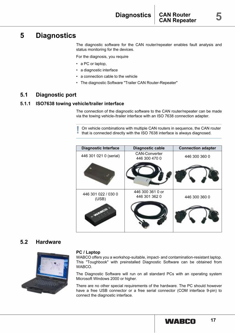
The connection of the diagnostic software to the CAN router/repeater can be madevia the towing vehicle-/trailer interface with an ISO 7638 connection adapter.
! On vehicle combinations with multiple CAN routers in sequence, the CAN router that is connected directly with the ISO 7638 interface is always diagnosed.
5.2 Hardware
PC / LaptopWABCO offers you a workshop-suitable, impact- and contamination-resistant laptop.This "Toughbook" with preinstalled Diagnostic Software can be obtained fromWABCO.
The Diagnostic Software will run on all standard PCs with an operating systemMicrosoft Windows 2000 or higher.
There are no other special requirements of the hardware. The PC should howeverhave a free USB connector or a free serial connector (COM interface 9-pin) toconnect the diagnostic interface.
Diagnostic Interface Diagnostic cable Connection adapter
446 301 021 0 (serial)CAN-Converter446 300 470 0 446 300 360 0
446 301 022 / 030 0 (USB)
446 300 361 0 or446 301 362 0 446 300 360 0

18
5 CAN RouterCAN Repeater
Diagnostics
Diagnostic Interface SetTo set up the diagnosis, the WABCO Diagnostic Interface Set with order number 446301 030 0 (USB connection) is required. The set contains the Diagnostic Interfaceand a USB connecting cable to the PC or laptop.
The old Diagnostic Interfaces with serial connection (446 301 021 0) and with USBconnection (446 301 022 0) can still be used.
5.3 Diagnostic Software
There are three ways to obtain the "Trailer CAN Router-Repeater" diagnosticsoftware:
• Offline as a USB stick version
• Online as a single download
• As a part of a WABCO system diagnostics subscription
For the diagnosis of multiple WABCO systems, WABCO offers you four differentDiagnostic Software subscriptions via the Internet. These contain numerousdiagnostic programs at one very low price.
On the Internet, on Web page www.wabco-auto.com in the quick access area, clickon "Diagnosis" and then on "WABCO System Diagnostics". There, you will findfurther information and can order the Diagnostic Software in your language and toload onto your PC.
5.3.1 Diagnostic Software "Trailer CAN Router-Repeater"
If a diagnostics connection exists, the diagnostic software recognises, when starting,which system – whether CAN Router or -Repeater – is connected and adapts thedisplay of the diagnostic software accordingly.
The following important tasks are covered by the diagnosis:
Diagnostic memory Under menu point "Messages/Diagnostic memory“, current and aged system errorsand notes are shown (see chapter 6.1 „Diagnostic messages“, page 20).
The diagnostic memory can be deleted with the respective button.
Status monitoring • Monitoring the CAN communication between the CAN router/repeater and the T-EBS modulator
If a fault is reported in the CAN communication, the cable connection must bechecked.
If multiple CAN routers are connected in series, each device must be checkedindividually. Always choose the interface directly before the CAN router for checkingthe communication status to the downstream T-EBS modulator or attached router.
• Monitoring the status of the warning lights

19
5CAN RouterCAN Repeater
Diagnostics
Faults in CAN communication and warning light messages are shown as follows:
Fig. Screenshot Diagnostic Software: Faulty CAN communication to Trailer #2
Monitoring the external
nominal pressure
sensor
In menu "System / Deactivate fault monitoring of pressure sensor", the faultmonitoring for the external nominal pressure sensor can be deactivated.
When delivered, the fault monitoring of the external nominal pressure sensor isdeactivated on the CAN router/repeater. The fault monitoring is activated when thesensor is connected for the first time.
If it is connected again after replacing the sensor, the monitoring is activated againautomatically. In this case, the fault monitoring must be deactivated again.
! As of version 1.5 of the Trailer EBS E (production date from CW 49/2009), in the diagnostic software "Trailer EBS E" with connected external pressure sensor on the CAN router/-repeater, select setting: "Nominal pressure sensor on R/R" to improve the communication between the devices.
ECU Software Update In the "System / ECU Update" menu, the software for the CAN router/repeater canbe updated. Updates for the ECU software are provided in file format and can beloaded into the ECU with the diagnostic software.
– Pay attention to the messages and follow the instructions of the diagnosticsoftware during the ECU software update.
! Only software that has been officially released by WABCO is to be loaded into the ECU of the CAN router/repeater.

20
6 CAN RouterCAN Repeater
Appendix
6 Appendix
6.1 Diagnostic messages
Fig. Screenshot Diagnostic Software: "Diagnostics memory"
Component
Type of fault
Component
Type of fault
Note
Code Message
78 External desired-pressure sensor
220 CAN data link connection Power_IN
183 CAN data link connection Power_OUT1
184 CAN data link connection Power_OUT2
251 Power supply connection Power_IN
181 Power supply connection Power_OUT1
182 Power supply connection Power_OUT2
253 Parameter setting
254 Control unit
255 Internal operating software
Code Message
0 Value too high
1 Value too low
2 Data is irregular or incorrect
3 Overvoltage/Short circuit to 24 V
4 Undervoltage/ Short circuit to ground
5 Permanent current consumption
6 Current too high or circuit grounded
7 Air gap too big
8 Slip
9 Signal failure
10 Jump up / Jump down
11 see note
12 see note
13 Characteristic curve information
14 Special message/ see message info
15 see note

21
6CAN RouterCAN Repeater
Appendix
Note
Code Message
25412 Internal ECU message. Switch off ignition for 5 seconds. If message still exists, replace device.
25512 Internal operating system message: Switch off ignition for 5 seconds. If message still exists, replace device.
25103 Connection between Router/Repeater and towing vehicle (Power_IN): Voltage on pin 1 or 2 from towing vehicle is too high.
25104 Connection between Router/Repeater and towing vehicle (Power_IN): The voltage from the towing vehicle is below 8 V or the connection at PIN 1 or 2 of the trailer coupling is broken. Message can also exist in towing vehicle.
18103 Connection between Router/Repeater and trailer modulator (Power_OUT1): Supply voltage too high. This message occurs if the voltage supplied from the towing vehicle is too high.
18104 Connection between Router/Repeater and trailer modulator (Power_OUT1): Interruption in the supply voltage. The internal fuses F1 or F4 can be defective in the Router/Repeater. Check fuses.
18203 Connection between Router/Repeater and towed vehicle (Power_OUT2): Voltage on pin 1 or 2 from towing vehicle is too high. This message occurs if the voltage supplied from the towing vehicle is too high.
18204 Connection between Router/Repeater and towed vehicle (Power_OUT2): The connection via pin 1 or 2 of the trailer plug-in connection is interrupted. The internal fuses F2 or F3 can be defective in the Router/Repeater. Check fuses.
25313 Internal parameter message. Switch off ignition for 5 seconds. If message still exists, replace device.
25314 Parameter message. Switch off ignition for 5 seconds. If message still exists, replace device.
18413 CAN data received from a 6th vehicle. A maximum of 5 vehicles are supported in a road train. 6th vehicle must be disconnected. Then switch ignition off and on again.
22005 Connection between Router/Repeater and towing vehicle (Power_IN): Interruption on pin 6 or 7 (CAN H or CAN L) of the trailer plug-in connection between the trailer and the towing vehicle. Check plug-in connection. Message can also exist in the towing vehicle.
18305 Connection between Router/Repeater and trailer modulator (Power_OUT1): Interruption on pin 2 or 1 (CAN H or CAN L) of the connection between the Router/Repeater and trailer modulator. Check connection between devices. Is the bayonet connection plugged in?
18312 Expected CAN data was not received from the trailer modulator. Is the trailer modulator connected with the connection Power_OUT1? Has the connection with the towing vehicle or the towed vehicle been swapped?
18405 Connection between Router/Repeater and towed vehicle (Power_OUT2): Interruption on pin 6 or 7 (CAN H or CAN L) of the trailer plug-in connection between the trailer and the towed vehicle. Check plug-in connection. Message can also exist in the towed vehicle.
7803 The cable between the Router/Repeater and the external desired-pressure sensor is defective.
7804 The cable between the Router/Repeater and the external desired-pressure sensor is defective.
7805 The cable between the Router/Repeater and the external desired-pressure sensor is defective.
7813 Measured pressure is implausible. Check the pneumatic connection of the pressure sensor in the control line.

22
6 CAN RouterCAN Repeater
Appendix
6.2 Drilling template

23
6CAN RouterCAN Repeater
Appendix
6.3 Diagram
Configuration / Components
Diagram
84
1 6
01
28
7 0
84
1 7
01
22
8 0
84
1 6
01
24
5 0
84
1 7
01
05
5 0
84
1 7
01
05
7 0
84
1 7
01
05
8 0
CAN Router X X X
CAN repeater with pressure sensor X X X
Select High for RSS in Eurocombi / Roadtrain X X
Select Low for trailing steering axle X
3. Modulator / EBS relay valve for last axle / trailing steering axle X X
PREV X X X X
Trailer release valve X X

24
6 CAN RouterCAN Repeater
Appendix
6.3.1 CAN Router
841 601 287 0 Trailer EBS E with CAN router, 4S/2m or 2S/2M in dolly for Eurocombis or Roadtrains with Select High valve for improved RSS control in entire vehicle

25
6CAN RouterCAN Repeater
Appendix
841 701 228 0 Trailer EBS E with CAN router, 4S/2M or 2S/2M in dolly for flatdecks / semitrailers with Select High valve for improved RSS control in entire vehicle

26
6 CAN RouterCAN Repeater
Appendix
841 601 245 0 Trailer EBS E with CAN router, 2 x 2S/2M in a vehicle

27
6CAN RouterCAN Repeater
Appendix
6.3.2 CAN Repeater
841 701 055 0 Trailer EBS E with CAN repeater for overlength trailers 4S/3M with trailer release valve and PEM

28
6 CAN RouterCAN Repeater
Appendix
841 701 057 0 Trailer EBS E with CAN repeater for overlength trailer 4S/3M with PREV and Select Low for trailing steering axle

29
6CAN RouterCAN Repeater
Appendix
841 701 058 0 Trailer EBS E with CAN repeater for overlength trailers 4S/3M with EBS relay valve and trailing steering axle