canadian nuclear society international conference on
TRANSCRIPT

ISBN 0-919784-00-3
INIS-mf—9040
HNS Canadian Nuclear Society
INTERNATIONAL CONFERENCEON
RADIOACTIVE WASTE MANAGEMENT
CONFERENCE SUMMARIES
1982 SEPTEMBER 12 TO 15WINNIPEG CONVENTION CENTREWINNIPEG, MANITOBA, CANADA

JCANADIAN NUCLEAR SOCIETY
INTERNATIONAL CONFERENCEON
RADIOACTIVE WASTE MANAGEMENT
1982 SEPTEMBER 12 TO 15WINNIPEG CONVENTION CENTREWINNIPEG, MANITOBA, CANADA
Conference Organizing Committee
Conference Chairman
Technical Program Chairman
Treasurer/Publications
Facilities Coordinator
Guest Program
Executive Member
T.S. Drolet (Ontario Hydro)
M.A. Feraday (AECL-CRNL)
N. Yousef (Ontario Hydro)
E.L.J. Rosinger (AECL-WNRE)
E. Card (Wardrop & Assoc.)
S. Trussart (Hydro Quebec)
Technical Review Committee
C.R. Bennett (AECL-EC)
L. Cabeza (MacLarens)
M.L. Calzolari (Ontario Hydro)
D.J. Cameron (AECL-WNRE)
T.J. Carmichael (Ontario Hydro)
A.T. Grange (Ontario Hydro)
G. Grant (AECL-WNRE)
R.B. Lyon (AECL-WNRE)
S.A. Mayman (AECL-WNRE)
D. Noonan (Colder Assoc.)
L.R. Olden (Ontario Hydro)
- l -

J
Table of Contents
PAGE
Plenary Session A
1 Keynote Address -R.G. Hart, Executive Vice-President 1AECL-RC, Ottawa)
2 The Canadian Nuclear Fuel Waste Management Program, 2T.E. Rummery, E.L.J. Rosinger (AECL-Whiteshell)
3 IAEA Activities in Radioactive Waste Management, K. Barabas 5(IAEA-Vienna)
4 International Co-operation in Radioactive Waste Management: 7The OECD Nuclear Energy Agency Programme, P.D. Johnston(OECD/NEA-Paris)
5 European Community Programs on High Level Waste, 10S. Orlowski (CEC-Brussels)
6 The U.S. Strategy for the Development and Construction of 15High-Level Radioactive Waste Repositories, W. WadeBallard, C.R. Cooley, D.G. Boyer (USDOE-Washington)
7 Swedish Radioactive Waste Management, T. Papp (SKBF/KBS- 18Sweden)
Parallel Session 1A - Engineered Barriers
1 Canadian Engineered Barriers Program, K. Nuttall, 20D.J. Cameron, F.P. Sargent (AECL-Whiteshell)
2 Assessing Corrosion of Nuclear Fuel Waste Containers, 24P. McKay, K. Nuttall, D.B. Mitton (AECL-Whiteshell)
3 Design of Packed Particulate Supported Containment for ^7Irradiated Fuel Immobilization, M. Mikasinovic, R. Hoy(Ont. Hydro-Toronto)
4 Preliminary Evaluation of the Design of Particulate- 31Packed, Thin-Wall Container for Disposal of IrradiatedFuel Bundles, B. Teper (Ont. Hydro-Toronto)
5 The Effect of Air Contamination in the Shielding Gas on 36the Mechanical Properties of Ti, G.T.A. Welds,Peter Y.Y. Maak (Ont. Hydro-Toronto)
6 Development of a High Integrity Container for Burial of 40Special Waste, R.L. Chapman, R.E. Holzworth, A.L. Ayers Jr.,R.T. Haelsig (EGSG-Idaho)
- iii -

JParallel Session 1A - Cont'd
7 Laboratory Study of Physical Properties of Clay Buffersfor a Nuclear Fuel Waste Vault, H.S. Radhakrishna,H.T. Chan (Ont. Hydro-Toronto)
8 Laboratory Study of Clay-Type Grouting Materials, H.T. Chan(Ont. Hydro-Toronto)
9 A Review of Cement Based Grouts for Both RepositorySealing and the Construction of the Underground ResearchLaboratory, R.D. Hooton, P.K. Mukherjee (Ont. Hydro-Toronto)
PAGE
44
46
48
Parallel Session IB - Geoscience for Fuel Waste Disposal I
1 Applied Geoscience Research in the Canadian Nuclear Fuel 50Waste Management Program, S.H. Whitaker (AECL-Whiteshell)
2 The Identification and Characterization of Major Structural 53Discontinuities within the Eye-Dashwa Lakes Granite,Atikokan, NW Ontario, P.A. Brown, N.A.C. Rey (AECL-GSC,Ottawa)
3 Pore Structure Parameters of Igneous Crystalline Rocks - 57Their Significance for Potential Radionuclide Migration,T.J. Katsube (GSC-Ottawa)
4 Permeability Assessment of the Near-Excavation Zone, 59A.T. Jakubick (Ont. Hjfdro-Toronto), V. deKorompay(Beaconsfield, Quebec)
5 Influence of Heat Flow on Drift Closure During Climax 60Granite Spent Fuel Test: Calculations and Measurements,T.R. Butkovich, J.L. Yow Jr., D.N. Montan (LLNL-California)
6 In Situ Permeability and Heater Tests on HLW Disposal 62Technology Developments in Japan, K. Maekawa,T. Kashiwagi (Mitsubishi), N. Tsunoda (PNC), Tokyo, Japan
7 Design and Construction of Exploratory Shafts for Under- 66ground Nuclear Waste Storage, P.K. Frobenius, C.L. Wu(Bechtel-San Francisco)
8 Considerations in the Design of High-Level Waste 68Repositories in Crystalline Rocks, J.A. Allison, L.M. Lake(Mott, Hay & Anderson-England)
9 Engineering Aspects of Geologic Waste Isolation, L.A. White, 72D.L. Pentz (Golder Associates-U.S.A.)
- iv -

JParallel Session IB - Cont'd
10 The Use of Uranium-Series Disequilibrium to DetermineRadionuclide Migration on Geologic Time Scales,M. Gascoyne (AECL-Whiteshell)
PAGE
78
Parallel Session 1C - Low Level and Reactor Wastes I
1 Characterization of Low Level Radioactive Haste in Canada, 81Alex Buchnea (MacLaren-Toronto) INVITED
2 Controlled Air Incineration of Radioactive Wastes at the 85Los Alamos National Laboratory, L. Eitretz, L. Borduin,A. Neuls (LANL-New Mexico)
3 Development of Pyrohydrolysis for Reactor Waste Volume 87Reduction, C D . Desjardins, R.S. Salter (NBRPC-New Bruns-wick) , L.P. Buckley, K.A. Burrill (iiECL-Chalk River)
4 The Influence of Leachant Composition on the Release of 90Cs-137 from Ion-Exchange Wastes Immobilized in Thermo-setting Polymer Binders, A.P. Haighton (CEGB-England)
5 Comparing Cement, Plastic and Bitumen Immobilization for 94Liquid and Solid Reactor Wastes, L.P. Buckley (AECL-Chalk River)
6 Leaching Behaviour of Metal Hydridess Containing 97Immobilized Tritium, J.M. Miller (MICL-Chalk River)
7 Leach Behaviour and Mechanical Integrity Studies of 101.Irradiated Epicor-II Waste Products, R.E. Barletta,K.J. Swyler, S.F. Chan, R.E. Davis (BNL-New York)
8 Radiolytic Effects on Ion Exchange During the Storage 104of Radioactive Wastes, K.K.S. Pillay (LANL-New Mexico),G.E. Palau (Penn State U.)
9 Radioactive Liquid Filter Wastes Handling at Darlington 107GS, A.D. Mackle, K.K. I,o (Ont. Hydro-Toronto)
Parallel Session ID - Public Attitudes, Regulatory
1 Social Aspects of Siting Geologic Research Areas for 109Nuclear Fu>l Waste Management - The Canadian Experience,E.R. Freeh (AECL-Whiteshtsll) INVITED
2 Developing Social Impact Assessment Methodologies for 112Long-Term Disposal of Irradiated Fuel, B.G. Rogers,M.A. Stevenson (Ont. Hydro-Toronto)
- v -

JParallel Session ID - Cont'd PAGE
3 The Role of the Media in Structuring Public Concerns 115about Nuclear Fuel Waste Management, G.M. Gilmour(Consultant-Scarborough), Bryn Greer-Wooten (YorkUniv.-Dovmsview)
4 The Ontario Public's Opinion of Nuclear Fuel Waste Manage- 118ment, M.A. Greber, M. Barrados (AECL-Ottawa)
5 The AECB Approach to Concept Assessment for High-Level 121 iRadioactive Waste Disposal, P. Conlon, K.P. Wagstaff(AECB-Ottawa)
6 A Practical Application of Criteria for the Clean-up of 123Contaminated Communities, R.S. Eaton (AECB-Ottawa)
Plenary Session B
1 Low- and Intermediate-Level Radioactive Waste Management 125in Canada, D.H. Charlesworth (AECL-Chalk River),T.J. Carter (Ont. Hydro-Toronto)
2 The Low Level Waste Management Program in the United 127States, G.B. Levin (EG&G-Idaho)
3 The Japanese Approach for the Management of Radioactive 129Wastes, T. Ishihara (RWMC-Tokyo)
4 United States Department of Energy Surplus Facilities 130Management Program, J.F. Nemec (UNC), J.D. white (USDOE)Richland
5 The Present Status and Future Plans for the Regulation of 132Radioactive Wastes in Canada, W.D. Smythe (AECB-Ottawa)
6 Bioethical Issues in Radioactive Waste Management, 135Margaret N. Maxey (Univ. of Texas-Austin)
7 Hazards from Radioactive Waste in Perspective, B.L. Cohen 138(Univ. of Pittsburgh)
Parallel Session 2A - Performance, Assessment and Modellingfor Nuclear Fuel Waste Disposal Facilities
1 Nuclear Waste Disposal-Performance Assessment: Principles 140and Procedures, R.B. Lyon (AECL-Whiteshell)
- vi -

JParallel Session 2A - Cont'd PAGE
2 Reference Environment Modelling for Generic Environmental 143Assessment of the Canadian Nuclear Fuel Waste DisposalConcept (Pre-Closure), J.H. Gee (Ont. Hydro-Toronto)
3 A Stochastic Model for the Dissolution of Irradiated 146U02 Fuel, B.W. Goodwin, L.H. Johnson, R.J. Lemire (AECL-Whiteshell)
4 An Approximate Analytical Procedure for Solving a Radio- 148nuclide Transport Equation, G.L. Moltyaner (AECL-ChalkRiver)
5 A Model on Nuclide Migration in Unsaturated Zone, 151H. Tasaka, T. Asano, Y. Akimoto (Mitsubishi-Tokyo)
6 The Role of Thermomechanical Modeling in the Selection 154of a Salt Repository Site in the USA, H.Y. Tammemagi,M.C. Loken, R.A. Wagner (RE/SPEC-Rapid City S.D.),M.R. Wigley (ONWI-Columbus)
7 Long Term Stability Analysis - The Battelle Geologic 159Simulation Model, M.G. Foley, G.M. Petrie (BPNL-Richland) INVITED
8 A Comparative Safety Analysis of the Disposal of Spent 161Fuel and the Other LWR Wastes in Hard Bedrock,E.K. Peltonen, S.J.V. Vuori (TRCF-Helsinki)
9 Simulations of Long Term Health Risk from Shallow Land 163Burial of Low Level Radioactive Wastes, C.A. Little,D.E. Fields (ORNL-Oak Ridge)
Parallel Session 2B - Mine/Mill Waste Management
1 Overview of Current Uranium Tailings Management Practice, 167D.B. Chambers, R.A. Knapp (SENES-Willowdale)
2 Uranium Tailings in Canada - Regulation and Management, 169R.S. Boulden, K. Bragg (AECB-Ottawa)
3 Uranium Tailings Management Practices at Elliot Lake, 171Ontario, J.B. Davis (Golder-Mississauga), K.B. Culver(Rio Algom-Elliot Lake), P.F. Pullen (Consultant-Oakville)
4 Uranium Mine Waste Management in Saskatchewan, D.W. Larson, 172B.E. Robertson (Univ. of Regina), R.J. Woods (Univ. ofSask-Saskatoon)
5 Uranium Processing: What Wastes?, A.W. Ashbrook, D. Moffett 174(ENL-Ottawa), J.P. Jarrell (ENL-Port Hope)
- vii -

Parallel Session 2B - Cont'd
6 Development of a Precipitation and Filtration Process for 177Ra-226 Removal from Uranium Milling Effluents,D.W. Averill (Envir. Canada) D. Moffett (ENL-Ottawa),R.T. Webber (Denison-Elliot Lake), J.W. Schmidt (Envir.Canada-Burlington)
7 Development of a New Process for Treating Uranium Tailings 181Decants, P.M. Huck, B. Anderson, R. Andrews, X.Bing-Song(Univ. of Regina-Regina)
8 Ultrafiltration for Radium Removal from Liquid Streams 182at a Uranium Mill, B.M. Mitchell (AECL-Chalk River)
9 Uranium Mine/Mill Decommissioning in Saskatchewan, 184R.R. Sentis, C.L. Potter, E.P. Wagner, R.G. Barsi(SasJc. Envir.-Prince Albert)
10 The Reclamation and Closeout of the Beaver Lodge Operations 186of Eldorado Nuclear Limited, A.W. Ashbrook (ENL-Ottawa),R.J. Phillips (ENL-Saskatchewan), M. Pilion (ENL-Ottawa)
Parallel Session 2C - Waste Product Research and Processing
1 Canadian R & D on High-Level Waste Products and Processes, 188A.G. Wikjord, D.W. Shoesmith, F.P. Sargent (AECL-Whiteshell)
2 Liquid Immiscibility in Multicomponent Borosilicate Glasses, 191P. Taylor, A.B. Campbell, D.G. Owen (AECL-Whiteshell)
3 Determination of 1-129 in Fuel Leaching Solutions by 193Neutron Activation Analysis, K.I. Burns, C.J. Moore(AECL-Whiteshell), E.M. Ashbourne (McMaster University-Hamilton)
4 Mechanism of Oxidative Dissolution of UO Under Waste 195Disposal Vault Conditions, S. Sunder, D.W. Shoesmith,M.G. Bailey, G.J. Wallace (AECL-Whiteshell)
5 Gas Phase Abatement of Radioiodine, A.C. Vikis, 199D.F. Torgerson (AECL-Whiteshell), L.P. Buckley (AECL-Chalk River)
6 Solution Chemistry of Technetium and Iodine, J. Paquettei 201S.J. Lister, W. Lawrence (AECL-Whiteshell)
7 Release of Cs-134, -137, and 1-129 from the Fuel/Sheath 203Gap of CANDU Irradiated Fuel, K.I. Burns, C.J. Moore,D.G. Boase (AECL-Whiteshell)
- viii -

JParallel Session 2C - Cont'd
8 Management Modes for the Radionuclides Tritium, C-14 207and Kr-85 Arising from Reprocessing, H. Brucker(ICT, Julich-Germany)
9 Characterization of the Off-Gas Released from CANDU Fuel 211to the Dissolver Off-Gas System to the Eurex Pilot Plant,G.G. Alonzo (Eurex-Saluggia), F.F. Castellani, G.G. Curzio,A.P. Gentili, L.P. Pieve (UN-Pisa)
Parallel Session 2D - Interim Storage, Transport andHandling of Spent Fuel
1 Long Term Storage Options for Ontario Hydro's Irradiated 216Fuel, B.P. Oalziel, S.J. Naqvi, P.K.M. Rao (Ont. Hydro-Toronto)
2 MODREX - An Answer to the Spent Nuclear Fuel Storage 220Dilemma, B.J. Baxter, F.D. Postula (G.A.-San Diego),H.B. Brooks (TVA-Tenn.)
3 An Evaluation of Concrete Casks for the Management of 225Irradiated Fuel, J. Freire-Canosa (Ont. Hydro-Toronto)
4 The Characterization of Irradiated CANDU Fuel Bundles 229Stored in Concrete Canisters at WNRE, K.M. Wasywich,J.D. Chen, K.I. Burns, D.G. Boase (AECL-Whiteshell)
5 Tritium Permeation Through the Cast Alloy Walls of a 232Spent Fuel Dry Cask, D. Stover (KFA-IRE, Julich),J. Fleisch (DWK-Hannover-Germany)
6 A Transient Multi-Dimensional Approach to Analyse the 235Thermal Performance of Pre-Disposal Nuclear WasteManagement Facilities, A.M. Chan, A.K. Ahluwalia(Ont. Hydro-Toronto), S. Banerjee (Univ. of Calif.-Calif.)
7 A Program for the Transportation of Irradiated Fuel, 239P.K.M. Rao, M.E. Gavin, K.E. Nash (Ont. Hydro-Toronto)
8 FFTF Radioactive Solid Waste Handling and Transport, 242J.D. Thomson (HEDL-Richland)
- ix -

Parallel Session 3ft - Low Level and Reactor Wastes II
1 Hydrologic and Geological Aspects of Low Level Radioactive 246Waste Site Management, N.H. Cutshall (ORNL-Oak Ridge)
2 Hydrogeological Program for Bruce NPD Radioactive Waste 249Operations Site 2, C.P. Lee, T.J. Carter, R.J. Heystee(Ont. Hydro-Toronto)
3 Groundwater Transport of Reactive Contaminants Near the 251CRNL Waste Management Areas: Some Realities, R.W.D. Killey(AECL-Chalk River)
4 Mobility of Cs-137 in the Ottawa River Near the CRNL Waste 253Management Areas, R.J. Cornett, E.L. Cooper, G. Lahaie(AECL-Chalk River)
5 Preliminary Analysis of Intrusion into a Low Level 256Radioactive Waste Emplacement at a Shallow Depth,L. Cabeza, C. McKenna, A. Buchnea (MacLaren-Toronto),J. Mernagh (Ont. Hydro-Toronto)
6 Assessment of Hypothetical Disposal Facilities for 259Canada's Low Level Radioactive Waste, A. Buchnea,L. Cabeza, E.J. Chart (MacLaren-Toronto), D.B. Chambers,L.M. Lowe (SENES-Willowdale)
7 Temporary Storage of Low Level Waste - Facility Design Experience, 263R.J. Tosetti, F. Feizollahi, H.E. Howell (Bechtel-San Francisco)
8 An Approach to the Exemption of Materials from Regulation 266As Radioactive Wastes, R.M. Chatterjee, J.R. Coady,K.P. Wagstaff (AECB-Ottawa)
9 Carbon-14 in Ion Exchange Resins from Finnish Nuclear 268Power Plants, M. Snellman (TRCF), L. Salonen (IRP-Finland)
10 An Overview of the Ontario Hydro Carbon-14 Control Program, 270R.R. Stasko, G.A. Vivian (Ont. Hydro-Toronto)
Parallel Session 3B - Environmental, Health and Safety
1 Canadian Environmental Research for Nuclear Waste Manage- 273ment, S.L. Iverson (AECL-Whiteshell)
2 Radioecology and Waste Management, A. Grauby (CEA- 276Cadarache)
- x -

JParallel Session 3B - Cont'd
3 A Model to Calculate Doses From Iodine-129 on a Local, 278Regional and Global Scale from the Proposed CanadianHigh Level Waste Vault, J.R. Johnson (AECL-Chalk River),D.M. Wusohke (AECL-Whiteshell), J.G. VanHeteren(AECL-Chalk River)
4 Ecological Vectors of Radionuclide Transport at a Solid 283Rad.ioactive Waste Disposal Facility in SoutheasternIdaho, W.J. Arthur, O.D. Markham (USDOE-Idaho Falls)
5 A Contamination Assessment Study for Gentilly Waste 286Storage Facilities, C. Marche (Ecole Polytechnique-Montreal), C. Schneeberger (Geos. Inc.-Montreal),S. Trussart, M. Lavallee (Hydro Quebec-Montreal)
6 Analysis of Atmospheric Pathways of Exposure at Jackpile 292Mine, M.H. Momeni, C.E. Dungey, C.J. Roberts (ANL-Argonne)
7 A Subsurface Migration Model for Use in Radiological 298Impact Assessment of Radioactive Waste Disposal,J.E. Mernagh, R.N. Sangster (Ont. Hydro-Toronto)
8 An In-Plant Radioactive Materials Pathway Model to 300Calculate Radioactive Emissions from CANDU PHWR Plants,D. Barber, J. Van Berlo (AECL-EC, Toronto)
9 Limitation of Future Dose Rate from Nuclear Wastes, 304W.R. Bush (AECB-Ottawa)
Parallel Session 3C - Geoscience for Fuel Waste Disposal II
Hydrogeological Research Program for High Level Waste 305Management at the US Nuclear Regulatory Commission,F.L. Doyle (USNRC-Washington)
Discussion of the AECB's Geological Criteria and Guidelines 307Germane to the Deep Underground Disposal of RadioactiveWaste, Joe Wallach (AECB-Ottawa)
The Nature of Fracture Fillings in the Eye-Dashwa Lakes 309Pluton, Atikokan, Ontario and their Significance toHydrogeological and Geochemical Aspects of Nuclear FuelWaste Management, D.C. Kamineni, D. Stone (GSC-Ottawa),T.T. Vandergraaf (AECL-Whiteshell)
Geological, Geophysical and Hydrogeological Investigations 311at the Site of the Planned Underground Research LaboratoryA. Brown (AECL,GSC-Ottawa), C.C. Davison, N.M. Soonawala(AECL-Whiteshell)
- xi -

rParallel Session 3C - Crait'd
5 Fracture Hydrology ar.-i Radionuclide Transport, P.J. Eourke, 313G.V. Evans (AERE-Harwell)
6 Regional and Room Scale Hydrological Simulations of the 317Atikokan Site, D.W. LaFleur, B.S. RamaRao, H. Reeves(INTERA-Calgary)
7 A Theoretical Analysis of Mass Transport in Fractured 319Media, F.W. Schwartz (Univ. of Alberta-Edmonton), L. Smith(Univ. of B.C.-Vancouver), A.S. Crowe (Univ. of Alberta-Edmonton)
8 Comparison of Theoretical and Experimental Models of Beat 321Transport from a Nuclear Waste Repository, A.T. Conlisk,R.N. Christensen, J. Roy (Ohio State Univ.-Columbus)
- xii -

7KEYNOTE ADDRESS
R. G. HartExecutive Vice President
Atomic Energy of Canada LimitedResearch CompanyOttawa, Ontario
FINAL SUMMARY PAPER NOT AVAILABLE AT TIMEOF PRINTING

- 2 -
THE CANADIAN NUCLEAR FUEL WASTE MANAGEMENT PROGRAM
T.E. Rummery and E.L.J. RosingerAtomic Energy of Canada Limited
Research CompanyWhiteshell Nuclear Research Establishment
Pinawa, Manitoba
During the past year there have been major technical achievements inCanada's Nuclear Fuel Waste Management Program. Significant progress hasbeen made on the environmental and safety assessment of the disposalconcept, laboratory and field research has advanced the data bank essentialto these assessments, and development of the Underground ResearchLaboratory has continued.
INTRODUCTION
In 1978, the Governments of Canada and Ontario announced an agreementto cooperate on a program of generic research and development for thedisposal of nuclear fuel wastes in a stable, crystalline rock formation inthe Canadian Shield. Atomic Energy of Canada Limited, a federal crowncorporation, has prime responsibility for research pertaining toimmobilisation and disposal, while Ontario Hydro, a provincially ownedutility, is charged with developing technologies for storage andtransportation of irradiated fuel. Since 1978, the program has grown tobecome truly national, with participation from several governmentdepartments, from industry and from the academic community. Externaltechnical review of the program is provided by the Technical AdvisoryCommittee, a group of distinguished scientists nominated by Canadianprofessional societies.
The research and development program on immobilization and disposalcan be divided into three major components:
. Immobilization of nuclear fuel wastes (both intact fuel bundlesand the wastes that would result from fuel reprocessing),
. Geoscience Research pertaining to the disposal of the immobilizedwastes, and
. Environmental and Safety Assessment of the disposal concept.
IMMOBILIZATION
For immobilization of irradiated fuel, high integrity containers,designed to provide fuel isolation for 300 to 500 years, are beingdeveloped. Current work is focussed on relatively thin-walled metalliccontainers with some form of internal support, such as a metal matrix orpacked particulate. The mechanical performance of container prototypeswill be determined in a hydrostatic test facility which will becomeavailable at the Whiteshell Nuclear Research Establishment during 1982.

- 3 -
Container corrosion rate will depend on the corrosion resistance ofthe metal and the disposal environment (e.g. saline groundwaters).Assessment of container materials has identified a number of potentially-suitable candidates, and detailed evaluation is underway. A review ofcopper, ceramic and other non-metallic materials for advanced, verylong-term containment is in progress.
Potential high-level waste forms, made from materials ranging fromglasses to crystalline products, are being investigated for immobilizationof the radioactive wastes that would arise from reprocessing of irradiatedCANDU* fuel. The leaching and dissolution behaviour of these materials,and of uranium oxide and irradiated fuel, are being studied to develop anunderstanding of the mechanisms and rates of the processes by whichimmobilized radionuclides might be released into groundwater.
GEOSCIEHCE RESEARCH
Geoscience Research involves development and evaluation of equipmentand methods for testing geologic formations, and characterisation of thosefeatures that may be important in the selection of a future disposal site.For example, field research providing data for the development of ourability to identify subsurface characteristics from measurements at thesurface and in boreholes is underway on granites at the Chalk River NuclearLaboratories, near the Whiteshell Nuclear Research Establishment (on theLac du Bonnet batholith), and near Atikokan in northwestern Ontario. Fieldresearch has also been initiated on two gabbroic bodies in Ontario.Results to date, which shown interdependence between various sets of fielddata, are very encouraging.
A below-surface research facility, the Underground ResearchLaboratory (URL), will be constructed about 15 km northeast of theWhiteshell Nuclear Reserach Establishment on the Lac du Bonnet batholith.The laboratory, now being designed and scheduled for completion in 1985,will consist of several small experimental rooms at two depths ofapproximately 150 and 250 m. The URL will provide an environment suitablefor in situ experiments in rock mechanics, hydrogeology, geochemistry andvault sealing. The data obtained from the experimental program will beused to assess computer models, mathematical predictions and the accuracy ofestimation of geological parameters at depth from surface measurements.The URL, in which no nuclear waste will be used or emplaced, will operatefor up to 15 years. Subsequently, it will be sealed and the site restoredand returned to the province of Manitoba.
ENVIRONMENTAL AND SAFETY ASSESSMENT
The objective of environmental and safety assessment is to estimatethe effects of storage, transporation, immobilization and disposal ofnuclear fuel wastes on man and the environment. The asessment, which
Canada Deuterium Uranium

- 4 -
incorporates information and data from all aspects of the program, willform the basis on which endorsement of the disposal concept will be soughtfrom the regulatory authorities, the technical community and the public.
The results from a preliminary radiological analysis of the storageand transporation of irradiated fuel show the total incremental dose to theexposed population to be less than 0.1 per cent of natural backgrounddose. An initial assessment of the long-term effects of a disposalfacility is encouraging. The maximum annual radiation dose to man fromnuclear fuel waste disposal has been estimated for 1730 differentscenarios. In 730 cases, the estimates showed no dose in the first millionyears, and the majority of the others indicated less than 1 per cent of theaverage dose from natural background radiation. In no case did the doseapproach that from natural background.
Feedback from the review process and advances in laboratory and fieldresearch are now being incorporated in the next assessment cycle.

- 5 -
IAEA ACTIVITIES IN RADIOACTIVE WASTE MANAGEMENT
K. BarabasInternational Atomic Energy Agency
Vienna, Austria
Today, in many countries nuclear power plants are in operation. At thepresent time, more than 8% of the world's electricity comes from 272 nuclearpower plants, and 238 plants are under construction. By 1985 we know that morethan 400 nuclear power plants will provide some 17% of the world's electricalenergy. In view of the increasing use of nuclear power in many Member States,the International Atomic Energy Agency is placing in its programmes continuedemphasis on the safe and effective management of all kinds of radioactive wastesthat arise from nuclear power plants and facilities of the nuclear fuel cycleincluding wastes from the mining and milling of uranium ores.
The IAEA programme in radioactive waste management addresses technolo-gical, environmental and safety aspects under the following major components:
- Waste management within nuclear facilities.
This covers the handling, treatment, conditioning and storage ofgaseous and liquid effluents and of all kinds and activity levelsof radioactive wastes, including the decontamination and decommissioningof uclear facilities.
- Underground disposal of waste.
This component addresses the disposal of low-, intermediate- and high-level wastes into the terrestrial subsurface, ranging from disposalat shallow depth through disposal in rock cavities to the emplacementin deep geological repositories.
- Environmental protection aspects of nuclear energy.
Within this part of the programme the Agency's responsibilitiesunder the London Convention on the Prevention of Marine Pollutionby Dumping of Waste, regarding the sea dumping of radioactive wastes,are dealt with and environmental pathways of radionuclides andenvironmental impacts related to radioactive and other dischargesfrom nuclear facilities are considered.
The objectives are to collect, review and disseminate technical, safetyand regulatory information, provide guidance and enhance the harmonization ofprinciples for the benefit of all Member Spates, with the assistance of expertsfrom nations advanced in the nuclear power field as well as those embarking onthe use of nuclear power. The paper describes current activities under theAgency's waste management programme.
The Agency's Waste Management Section is part of the Division of NuclearFuel Cycle within the Agency's Department of Nuclear Energy and Safety. Itfunctions through the effective use of experts and Agency staff from Member

States, in co-operation with those of other international organizations,participating primarily in various types of meetings and projects such asconferences and symposia, advisory groups, technical committees, consultants'meetings, coordinated research programmes, technical assistance projects andtraining courses. The products developed through these activities are pro-ceedings, Safety Series Reports, Technical Reports and other reports anddirect technical assistance.
While responsibility for waste management is primarily national, thereare also a number of areas in which there may be a desire or even a need forregional and international solutions or control, e.g. in the field of disposalof radioactive waste or the establishment of final disposal sites for high-level wastes.
The Agency's waste management programme involves co-operation in thesponsoring of meetings, exchange of information and consultation with manyinter-governmental and non-governmental organizations, such as UNEP, WHO, IMCO,UNESCO, UNSCEAR, NEA, ECE, CEC, CMEA, ICRP and UNIPEDE. The IAEA is preparingfor a major International Conference on Radioactive Waste Management whichwill be held from 16 to 20 May 1983 in Seattle, USA, and be dedicated to asummary review of the various technical, environmental, institutional, regula-tory and economic aspects of waste management and their implications on thedevelopment of nuclear power.

- 7 -
INTERNATIONAL CO-OPERATION IN RADIOACTIVE WASTEMANAGEMENT: THE OECD NUCLEAR ENERGY AGENCY PROGRAMME
P.D. JohnstonOECD Nuclear Energy Agency
Paris, France
The OECD is an international intergovernmental organization, of whichthe Nuclear Energy Agency (N1SA) is one of a number of specialized agencies.
The NEA has three main objectives in its radioactive waste managementprogramme s
- to promote studies and improve the data base available to supportnational programmes;
- to contribute to the effectiveness of S&D through co-ordination ofnational activities and promotion of international projects;
- to improve the general level of understanding of waste managementissues and strategies, particularly in waste disposal.
To achieve these objectives, the NEA programme of work isperiodically reviewesd by its Radioactive Waste Management Committee, astanding committee of senior governmental experts. This Committee, whichworks in close co-operation with specialized subgroups and the NEACommittee on Radiation Protection and Public Health on questions related toenvironmental protection, draws on the best international technicalexpertise. The NEA programme responds to the objectives at four levels:
- The first involves the sharing of information. This is realizedthrough the organization of expert meetings, the preparation oftechnical reports, and the analysis and dissemination of data.
- The second, of an operational nature, includes establishment ofjoint research and development projects designed to supportnational programmes*
- The third involves the implementation of the Multi-lateralconsultation and Surveillance Mechanism for sea dumping ofradioactive waste;
- The fourth concerns discussion of current issues and strategies inradioactive waste management. In this, the Radioactive WasteManagement Committee constitutes a specialized international forumfor discussion of waste management policies.

- 8 -
The management of radioactive waste from nuclear activities covers asequence of complex technical operations. However, as the ultimateobjective of radioactive waste management is disposal, the largest part ofthe programme is directed towards analysis of disposal options, inaddition, the NEA is active in various other areas of waste management,such as the treatment and conditioning of waste, the decommissioning ofnuclear facilities and the institutional aspects of the long-termmanagement of radioactive waste*
TREATMENT AND CONDITIONING
Numerous industrially proven methods already exist for the treatmentand conditioning of many radioactive wastes and international co-operationat government level is consequently limited to specific areas. Amongthese, the NEA programme includes studies on advanced treatment methods forcertain waste types, testing and characterization of solidified andpackaged waste products, and studies of the interaction between waste andthe disposal environment.
DISPOSAL
The NEA programme focusses on disposal of uranium mining and millingwastes which contain long-lived isotopes; the disposal of high-level andother long-lived wastes which are presently stored and which requirelong-term isolation in deep continental or sub-seabed geologicalformations, and -the disposal of low-level radioatctive waste into the deepocean. A study is also underway on the long-term radiological protectionobjectives for disposal of all types of radioactive waste, in particularconcerning applicability of existing ICRP Recommendations.
Management of Uranium Mining and Milling Wastes
At international level, increased consideration is given to theformulation of principles and guidelines for the proper management ofuranium mill tailings, considering both short-term and long-term factors.The NEA has a major programme in this field covering radiation protectionand engineering aspects of the disposal of uranium mill tailings.
Disposal of Low-Level Radioactive Wastes into the Dee; Ocean
This disposal method is regulated by the Convention on the Preventionof Marine Pollution by Dumping of Wastes and Other Matter (the so-called"London Convention", adopted in 1972 and in force since 1975). To furtherthe objectives of this Convention, the NBA operates a MultilateralConsultation and Surveillance Mechanism for Sea Dumping of RadioactiveWaste, under which OECD countries undertaking sea disposal' operationssubmit their operations to international review and surveillance. Tht SEA

has recently set up a Co-ordinated Research and Environmental SurveillanceProgram in connection with the North Atlantic disposal site. Thisprogramme should allow a more precise assessment of the safety of seadisposal practices.
Disposal of Radioactive Waste into Geologic Formations
For long-term isolation of high-level and other long-lived radio-active waste, geological formations can potentially provide the extendedcontainment required. The NEA programme is designed to identify the maintechnical problems and to provide a framework to help member countriesimprove the data available. This is done through specific studies andco-ordination of national activities. NEA expert groups and workshopsstudy topics such as the migration of radionuclides in the geosphere, theinfluence of waste on the local environment, and risk analysis ofpotential repository sites. These activities will contribute to a betterassessment of the safety and feasibility of the disposal concepts.
The NEA provides a framework for several international co-operativeprojects: the Stripa Project, located in Sweden, investigates hardcrystalline rock for isolation of nuclear waste; the International SorptionInformation Retrieval System (ISIRS) is a data bank on radionuclidesorption information in geological media; the Working Group on SeabedDisposal of Radioactive Waste exchanges information and co-ordinates R&Dactivities on the technical feasibility of disposal of long-livedradioactive wastes under the seabed.
DECOMMISSIONING OF NUCLEAR FACILITIES
In order to investigate the effectiveness of decontamination methodson reactor components, NEA has promoted an international research programmebased on the Agesta PWR reactor in Sweden. The first phase of this projectstarted in early 1982.
Information is also collected on nuclear plants which are planned tobe decommissioned within the next five years. Their analysis will identifyspecific decommissioning technology nesds and help to promote co-ordinatedactivities.
INSTITUTIONAL ASPECTS OF LONG TERM RADIOACTIVE WASTE DISPOSAL
NEA is using its extensive experience of regulatory questions,combined with its access tc technical expertise, to investigate the legal,administrative and financial aspects of long-term management of radioactivewaste. In addition to purely technical questions, this includes financialaspects, determination of operational responsibilities, third partyliability, and administrative surveillance.

- 10 -
EUROPEAN COMMUNITY PROGRAMS ON HIGH LEVEL WASTE
S< OrlowskiCommission of the European Communities
Brussels, Belgium
1. HIGH LEVEL WASTE IN THE EUROPEAN COMMUNITY (EC)
In 1980 the Member States(*) of the EC expressed the view that it isof common interest to keep open the option of recovering and re-using spentfuel discharged from nuclear reactors* Today, Member States engaged innuclear energy programs are reprocessing their fuel themselves or sendingit abroad for reprocessing while accepting the possibility that theresulting conditioned waste will be returned to them*
Such a policy has three consequences:
. High level waste subject to R and D programs are mainlyreprocessing waste
• Harmonized evaluation and quality control procedures forconditioned waste have to be developed at European level, as wellas the conditioning processes
• There is a common concern for high level waste disposal*
The European R and D programs are aiming to:
immobilize the waste in solid and stable forms, and developmatrices assuring long term integrity;
. dispose of the solidified waste into continental geologicalformations, or, possibly into deep marine sediments or bed rock*
Programs of the EC Member States cover all the aspects of HLWmanagement including industrial and commercial developments, while the ECResearch and Development program itself is devoted to coordinated orcomplimentary R and D activities, under the management of the EC Commission*
(*) Belgium, Denmark, France, Germany, Ireland, Italy, Luxembourg,The Netherlands, United Kingdom and Greece since 1981.

- 11 -
2. OVERVIEW OF THE NATIONAL PROGRAMS
Waste Immobilization
The main reference process for HLW immobilization appears to bevitrification* The concept has reached the commercial maturity in France(AVH process; the licence has been purchased by the UK and negotiations areunderway with Germany and Eurochemic (Belgium). Alternative vitrificationprocesses are being developed like the ESTER variant in Italy and the glassbeads concept in the Federal Republic of Germany (PAMELA process; prototypein construction, commissioning expected in 1983). Vitroceramics andsynrock type matrices are only looked at with a limited research effort.
Haste Disposal
Disposal into deep geological formations is the main option; however,no firm political commitment to one or another type of formations has beentaken up to now in the EC member States with the exception of the FederalRepublic of Germany; HLW disposal in salt domes is the German referenceconcept. The OK authorities took recently the view that HLW disposal willbe easier after a cooling tine of over 50 years and therefore cancelledtheir Research effort in that field (except for subseabed disposal which isnot as well studied as the continental alternatives).
Table 1 gives an overview of the situation in the EC countries.
3. THE EUROPEAN COMMUNITY R AND D PROGRAM
The EC program is carried out by the EC Commission in its ownresearch establishment, the "Joint Research Centre" (JRC, Ispra), and alsounder cost-sharing contracts with national laboratories. It covers allquestions related to radioactive waste management R and D; its part dealingwith HLW management can be divided in two major components:
- Evaluation of the conditioned products and development of qualitycontrol.
- HLW disposal into continental formations (salt, crystalline rock,clay) and into deep sediments of the sub-seabed.
a) The first activity is being dealt with by means ofinter-laboratory actions; it is aiming at developing appropriate methodsfor testing and evaluating waste products; qualified datas and possiblerelevant interactions with other substances will be provided as well.
The principal subjects investigated are presented in Table 2.
b) As shown on 'x'able 2, CEC disposal R and D includes a good part ofnational activities, besides complimentary studies.

- 12 -
A new emphasis was given recently to testing of the various barriers(glass, canister, backfill) under representative conditions, to a betterunderstanding of migration phenomena including the role of colloids/ and tothe evaluation of the confinement performances of the various geologicdisposal concepts*
The first phase of a concerted study on that topic has been launchedat the beginning of 1982 between the EC Member States and the EC Commission.

Table 1
GEOLOGICAL DISPOSAL OF HIGH-LEVEL WASTESR AND D PROGRAMS IN THE E.C.
Country
Belgium
France
FederalRepublic ofGermany
Italy
UnitedKingdom
DenmarkIrelandThe Nether-
lands
Options Studied
Clay *
*GraniteGneiss-Shale-Clayothers (salt)
Salt *
Clay*
GraniteClayOthers
Seabed
Salt
Salt
UndergroundLaboratory
MOL sitein progress;to be comoletedin 1983
- Site to beselected
- Start of workend of 1984
Asse Mine :- "cold" experi-ments since1978
- "hot" experi-ments startend of 1984
Selection ofexisting cavitiesin progress
DemonstrationPlant
- Site to beselected
- Start of work1992-95
GorlebenSite investiga-tions up to 1990(tentative sche-
dule)
Activities transferredon interim storage
- -
Supporting Activities
* Included in total or in part within the CEC program.

TABLE 2
VITRIFIED HIGH LEVEL WASTE
" . _ REFERENCE GLASS
RESEARCH SUBJECT " • .
BASIC LEACHIMG MECHANISM 8 CHEMISTRY
LEACHING TESTS UNDER DISPOSAL CONDITIONS
LEACHING PARAMETERS: T, P, PH, FLOW
LONG TERM (1 YEAR) LEACH TEST
RADIATION STABILITY
THERMAL STABILITY
MECHANICAL PROPERTIES
UK209
H U
H M U
H M U
H
H U
U
U
UK189
U
U
H M U
U
U
H U
C31/3CERAM.
H U
H U
H U
H
H U
H U
H
VG98/3
H
H
H
U
U
U
SON58
F M U
H M
H M U
F
U
U
H
SON64
F U
F U
M U
M U
PAMELABOROS.)
M
M
M
M
M
A : ABERDEEN UNIVERSITY/UKC : CNEN CASACCIA/ITALYF : CEA/FRANCEH : HMI BERLIN/GERMANY
K : KFK KARLSRUHE/GERMANYM : CEN MOL/BELGIUMR : RNL RISC/DENMARKU : UKAEA HARWELL/UK

- 15 -
THE U.S. STRATEGY FOR THE DEVELOPMENT AND CONSTRUCTIONOP HIGH-LEVEL RADIOACTIVE WASTE REPOSITORIES
W. Wade Ballard, Carl R, Cooley and D. Glenn BoyerOffice of Waste IsolationU.S. Department of Energy
Washington, D.C,
The Department's strategy for the development of permanent disposalfacilities for high-level radioactive waste is based on the Record of Deci-sion following the issuance of a final environmental impact statement. Thedecision states:
"The United States Department of Energy has decided to (1) adopt astrategy to develop mined geologic repositories for disposal ofcommercially-generated high-level and transuranic radioactivewastes (while continuing to examine subseabed and very deep holedisposal as potential backup technologies) and (2) conduct a researchand development program to develop repositories and the necessarytechnology to ensure the safe long-term containment and isolationof these wastes."
To accomplish these objectives and pursuant to procedural regula-tions of the Nuclear Regulatory Commission (NRC) at least three potentialsites in at least two different geological formations are being assessed forthe location of exploratory shafts to be constructed to the depths of themined repository horizon. The schedule calls for selecting the locationfor these exploratory shafts by the end of 1983j completing the constructionof the exploratory shafts by 1985; selecting one of these sites for a re-pository by 1987; submitting an application to NRC to begin the licensingprocedures for a repository by 1988; and completing the construction ofthe first mined repository in about 1998. We are looking at ways to acceleratethis schedule.
We believe it is vital to every country, and particularly for theUnited States, to carry out a strategy which does not delay decisions onfacilities for disposal. It is only by facing up to the decisions now, andthen moving into constructing and licensing of an actual repository can wedevelop the experience and confidence which must be associated with thesuccessful use of disposal facilities.
The U.S. Administration has emphasized the importance of movingquickly and as prudently as possible to establish qualified sites for per-manent disposal of radioactive wastes. Added emphasis has also been made onspending our budget wisely on the right activities and issues at the righttime.
The U.S. Congress, and its several committees, are combining theirefforts to establish comprehensive waste management legislation. Such legis-lation would address the site selection process and define a way to operatewith the States, the President, and the Congress. It would also definefinancing procedures and authorization to proceed.

- 16 -
Sources of revenue being studied in Congress include the assessmentof 1 mil per kW hr (i.e., 0.001 U.S. dollar/kWhr) of electricity generatedby nuclear power stations. This appears adequate to finance the programthrough 2000. Estimates indicate that 14 billion dollars would be raised,an amount sufficient to cover the 1.5 billion dollar cost of the repository,a test and evaluation facility, and a possible associated $200 million peryear of operating costs of the repository.
The National Waste Terminal Storage (NUTS) Program is progressing ona course of step-by-step decisions leading to a repository in the 1990's.Each step is being used to assure that uncertainties are properly mitigatedor compensated for in the decision process. The systems approach requiresthat the interrelated functions of each component of the system must be knownand described mathematically to project the performance of the disposal systemfor 10,000 years.
Work on the Hanford Site in basalt and the work at the Nevada TestSite in tuff is progressing. Both of the projects are to determine if thegeology is suitable for a repository at DOE-owned sites. The project managedfor DOE by Battelle's Office of Nuclear Waste Isolation is seeking a site indomed or bedded salt. The work in Mississippi, Louisiana, Texas, and Utahis expected to lead to the selection of a site for the first exploratory shaftinto salt. The confirmed capability to construct at each site will permitthe choice of one of the three sites for a possible test and evaluationfacility. Construction of a test and evaluation facility from 1986-1989 wouldpermit the emplacement of several hundred containers of waste in 1989. A"reduced scale" test and evaluation facility at a reference site or at aseparate location is being studied as a means to accelerate the overallschedule. Testing beyond 1989 would permit evaluation of waste handlingsystems before authorization is needed to operate the first repository.
Access through an exploratory shaft to the depth of a repository ateach site will open the opportunity to get information on the suitability ofeach host rock. In particular, the testing of the stress and change instresses, the testing of permeability of the rock and the hydrology surround-ing the repository level all provide the technical bases for selecting thefirst site for a repository. Where needed, horizontal drilling and tests inthe room at the bottom of the shafts can give confirmatory insight on theacceptability of a site.
The Department will continue to consult with the affected States on allsteps of the program. The Department has under development a plan for examina-tion of socioeconomic issues related to the NWTS Program. Individual Stateprograms must be developed to understand better certain benefits and also tomitigate adverse impacts resulting from the selection of a repository site.A "community planning document" is being developed to help State and localgovernments plan their individual development and evaluation programs.

- 17 -
The NWTS Program strategy provides a logical and practical way toachieve the Department's objectives. It brings the technology along in astepwise fashion to assure compliance with the NRC regulations, compliancewith the Environmental Protection Agency standards and response to the Na-tional Environmental Protection Act.
The growing support developing in the U.S. Congress, the support ofthe Administration and the recognition by the States of the importance ofresolving waste disposal issues, collectively is expected to continue andaccelerate progress on waste disposal decisions in the coming years.

J- 18 -
SWEDISH RADIOACTIVE WAST" MANAGEMENT
TOnis PappSwedish Nuclear Fuel Supply Company (SKBF/KBS)
Stockholm, Sweden
According to a new Swedish Act, valid from JUly 1981, the producerof the radioactive waste is technically and financially responsible forits safe management.
The Swedish nuclear utilities have entrusted the waste managementtask to the jointly owned Swedish Fuel Supply Company (SKBF).
A Government body. The National Board for Spent Fuel Management, issupervising the SKBF-work by reviewing the long-term planning. TheCommittee also administers the waste management fund built up by fees onthe nuclear power production and recommends annually the fee to be set bythe Government. For 1982 0.017 SEK will be funded per kWh producedelectric energy.
There are two main ways to achieve a safe final storage of theradioactivity in spent fuel. Either to deposit the fuel as it is or toreprocess the fuel and deposit the separated wastes. The R&U work \nSweden is covering both options with a main effort today on the complexchemical interactions in the near-field of deposited waste canisters.
Some parts of the total waste management system are required to beavailable at an early date* The construction of a central spent fuelstorage facility and a ship for waste transportation is underway.
The storage facility for spent fuel consists of a number of poolsin a rock cavern with about 30 m rock cover. Building licence wasgranted 1979 and the facility is scheduled to be ready to receive spentfuel by 1985. In a first phase the facility will be given a capacity of3000 tons of fuel. The capacity can be expanded to 9000 tons.
A coordinated Swedish sea-transportation system is planned for theradioactive wastes. A special ship for the transportation of spent fuelis under construction in France. Laying of the keel began in July 1981.The transportation system consisting of ship, transport casks andterminal equipment will be operational late 1982.
Presently the waste from the operation of the Swedish reactors arestored on-site. A central repository for the final disposal of thatwaste is in an early design phase. An application for a siting licencewas made this spring. If this is granted, the building of a finalrepository for reactor wastes will start in summer 1983. The facility isplanned to be operational in 1988. The repository consists of a systemof excavated caverns with 50 m rock cover under the Baltic Sea outside

- 1 9 -
the Forsmark nuclear power plant* This siting is chosen to give lowgroundwater gradients and high recipient dilution capacity.
Before final disposal of the high level waste from reprocessing orthe unreprocessed spent fuel a 40 year storage period is planned. Thisreduces the radioactivity and the heat generation of the waste. Thefinal repository must consequently be in operation by 2020.
The facility will be initiated about 500 m down in crystallinerock. Geological investigations in drillholes are now underway in threegneiss/granite areas in Sweden. Each area will be studied by surfacegeophysical methods and 5-8 core-drillholes down to between 600 and800 m. The cores are mapped, the hydraulic conductivity of the bedrockis measured and the deep groundwater will be chemically analyzed.
Between 10 and 20 areas will be investigated this way during the1980-ies. Around 1990 two or three sites will be selected for moredetailed investigations. The final selection and a siting license forthe final repository is anticipated around the year 2000. This willallow, not only for a ten-year construction period, but also for sinkingan investigation shaft down to 500 m and maybe a pilot facility duringthe first decade of the 21st century.
In the abandoned Stripa Mine an international OiSCD/NEA 4-yearproject is studying buffer material behaviour in a simulated repository,hydrogeological and geochemical conditions in boreholes at great depth,and the migration of nuclides in rock fissures. Further investigationsare discussed.
- 20 -
CANADIAN ENGINEERED BARRIERS PROGRAM
K. Nuttall, D.J. Cameron and F.P. Sargent,Atomic Energy of Canada Limited
Whiteshell Nuclear Research EstablishmentPinawa, Manitoba. ROE 1L0
The Canadian disposal concept is based on a multiple-barrierapproach to inhibit dissolution and transport of radionuclides by slowlymoving groundwater. This is perceived to be the only credible mechanismfor their return to the environment without the intervention of man [i].All of the commonly suggested components of such a system are beingresearched in Canada: waste forms, durable containment, buffers and back-fills to provide near-field barriers to diffusional and advective trans-port, and finally the geosphere, which is a massive spatial and sorptivebarrier to radionuclide migration from the vault to the biosphere. Thisreview deals only with the container and the buffer and backfill programssince the others are discussed in other sessions of this meeting.
CONTAINMENT
In Canada, research on the development of containment is concernedwith the fuel disposal option, although the technology being developedwould be readily applicable to blocks of solidified reprocessing waste.
Two containment targets have been proposed [2]. One would provideisolation for a period of about 500 years, during which the fission producthazard is high. The second is indefinite, but very long term, containment.If the container system is very durable, it would be expected that thepopulation of containers would fail over a long time interval, thusensuring a slow release of radionuclides independent of the mechanism ofwaste-form degradation.
For the first containment target, concepts based on the use of ashell of corrosion-resistant metal to contain intact fuel bundles are beingdeveloped. The first design studied was simply a hollow vessel to contain72 fuel bundles, designed to resist twice the hydrostatic pressure at 1000m depth. A prototype was built and tested (without fuel bundles) in ahydrostatic testing chamber. The collapse mode was as predicted, and thepressure at collapse was within 3$ of the predicted value [3].
Currently, three designs using a thinner corrosion-resistant shalland some internal means of supporting the shell are being developed. Theoptions for supporting the shell are;
- A cast matrix of lead, zinc or aluminum - 1% silicon alloy [4a,b],- A vibratory compacted, free-flowing particulate material L4cJ.- A rigid fuel basket made of carbon steel tubes and employing aparticulate to transfer the load from the outer shell to the tubulararray [ ]

- 21 -
Prototypes of all designs are being built and will be subjected tomechanical performance evaluation under vault conditons in a hydrostatictest facility, currently under construction at the Whiteshell HuclearResearch Establishment (WNRE).
The container shell materials of primary interest are titanium Grade2, titanium Grade 12, Inconel-625 and oxygen-free high conductivity (OPHC)copper [5]- Type j5i6L-stainless steel is also included in the studies, butwould be a candidate only if the vault environment were particularlybenign. Copper is a candidate only for the supported-shell designs, due toits low strength.
BUFFER AND BACKFILL
In conceptupl design studies, it was suggested that the wastepackage could either be placed in boreholes drilled in the floor of thevault and surrounded by buffer material [6], or be placed on a bed ofprepared buffer with additional buffer packed around and on top of thepackages [7]. The first option allows the use of a tightly consolidated,high quality material in rather limited quantities; the second would employa less consolidated, perhaps lower quality, material in much moresubstantial volumes, but with less opportunity for quality control. Theborehole buffer would, conceptually, be similar to the highly compactedbentonite proposed in the Swedish study, while the in-room buffer would besimilar to the backfill-
Preliminary property-evaluation programs [8] suggest that clayscontaining bentonite, illite and kaolin are potentially suitable as buffermaterials and as components of the backfill. The Canadian Shield inOntario has many clayey Quaternary deposits; some are tens of metres thick.Most contain illite and chlorite as the dominant clay minerals, but thereare deposits in Northwestern Ontario with a relatively high content ofsmectite [9]. Alternatively, there are large resources of clays, currentlybeing commercially exploited, in the Prairie provinces of Canada.
A major factor in determining the type of clay chosen as a primarycomponent of the buffer and backfill is chemical stability, which is afunction of vault temperature and groundwater composition. Variousproperties of candidate materials have been examined and, with input fromthe economic assessment, we hope to be in a position to define preferredmaterials within the next one to two years.
Near-field mass-transport modelling is in progress [io], tocontribute to the decision on which emplacement method to adopt, and toestablish realistic specifications for the buffer material properties.
In backfill development, a major question to be resolved is thechoice of filler material to be employed in conjunction with the claycomponent. The choice will be made from sand, gravel and crushed hostrock. The economic implications of this decision are being evaluated, anda study is being commissioned to examine the effect of texture andcomposition on the permeability, settling and segregation characteristicsof the backfill.

- 22 -
The use of additives in the buffer and backfill for redox controland selective radionuclide retardation ia also being researched [ii].
In the area of sealing technology, most of the work to date has beenconcerned with evaluation of the potential of using cements and clays togrout damage of the rock walls around low-permeability seals. The programis still at the laboratory stage, and is primarily concerned withinjectability and permeability measurements. A recent development is thestudy of micro-erosion of the clay-based grouts.
REFERENCES
1. J. Boulton (Editor), Management of Radioactive Fuel Wastes; TheCanadian Disposal Program, Atomic Energy of Canada Limited. Report,AECL-6314 (1978).
2. D.J. Cameron, Fuel Isolation Research for the Canadian Nuclear FuelWaste Management Program, Atomic Energy of Canada Limited. ReportAECL-6834 (to be published).
3. J.L. Crosthwaite, J.N. Barrie and K. Nuttall, Design, Fabrication andTesting of a Prototype, Stre3sed-Shell Fuel Isolation Container, AtomicEnergy of Canada Limited. Report, AECL-6S23 (to be published).
4. A.R. Gibson (Compiler); Waste Forms and Engineered Barriers;Proceedings of the Tenth Information Meeting of the Nuclear Fuel WasteManagement Program, Atomic Energy of Canada Limited. Technical Record,Tr-166 (1981). Unrestricted unpublished report, available from AtomicEnergy of Canada Limited, Research Company, Chalk River, Ontario KOJ1J0.
(a) P.M. Mathew, "Some Aspects of the Selection and Testing ofMatrixing Metals,: pp. 209-217.
(b) J.L. Crosthwaite, "The Design and Development of Metal-Matrixed,Supported Shell, Fuel Immobilization Containers", pp. 218-230.
(c) M. Mikasinovic and B. Teper, "The Design and Development Programfor the Packed-Particulate Supported Container", pp. 188-208.
(d) M.H. Cooper, "The Design and Development of a Structurally-Supported-Shell Container", pp. 231-240.
5. K. Nuttall and V.F. Urbanic, An Assessment of Materials for NuclearFuel Immobilization Containers, Atomic Energy of Canada Limited. ReportAECL-6440 (1981).
6. Acres Consulting Services Limited and Associates, A Disposal Centre forImmobilized Nuclear Waste: Conceptual Design Study, Atomic Energy ofCanada Limited Report, AECL-6416 (1980).
7. Acres Consulting Services Limited and Associates, A Disposal Centre forIrradiated Nuclear Fuel: Conceptual Design Study, Atomic Energy ofCanada Limited Report, AECL-6415 (1980).

- 23 -
9-
G.W. Bird, Selection and Evaluation of Buffer and Backfill Materialsfor a Deep Underground Nuclear Fuel Waste Disposal Vault, presented ata Workshop for Research Needs for Backfill for Underground NuclearWaste Management, 1981, April 13- Proceedings of the workshop toappear as an NBS Special Publication.
D.E. Desaulniers and J.A. Cherry, University of Waterloo, unpublishedreport (Project No. 903-05).
10. S.C.H. Cheung, G.W. Bird and C.B. So, Diffusion Modelling of theBorehole Emplacement Concept for a Nuclear Fuel Waste Disposal Vault,presented at the NBA Workshop on Near Field Phenomena, Seattle, (1981)September. Proceedings to be published.
11. G.W. Bird, Geoscience Canada 6, 199 (1979).

- 24 -
ASSESSING CORROSION OF NUCLEAR FUEL WASTE CONTAINERS
P. McKay, K. Nuttall and D.B. MittonAtomic Energy of Canada Limited
Whitesheil Nuclear Research EstablishmentPinawa, Manitoba
INTRODUCTION
A major objective in the Canadian program on engineered barriers,for nuclear fuel waste isolation, i s the development of a highly corrosionresistant container. The integrity of the container would be reasonablyassured for a period of time, sufficiently long to allow almost total decayof the fission-product inventory. If achieved, this would provide anabsolute barrier, independent of the geosphere, during the period when thewastes are most hazardous and the radiation fields and temperatures aroundthe wastes are at their highest. Radiolysis, in particular, could compli-cate assessments of nuclide solubility and near-field transport. Thispaper outlines an approach to assess.the suitability of candidate metals oralloys for this unprecedented period of corrosion service.
METHODS FOR ASSESSING CORROSION
The method will be illustrated by studies on grade-2 titaniun,which i s representative of the passive metals and alloys being consideredfor the corrosion-resistant shell of containers. The techniques developedshould be applicable to other candidate alloys displaying passivebehaviour. Titaniun i s intrinsically an extremely reactive metal; thestandard electrode potential for Ti/Ti i s around -1.6 V (SHE). However,i t undergoes spontaneous passivation, due to the formation of a veryprotective oxide film (TiOp), and even in concentrated chloride environ-ments at elevated temperatures (150°C), the corrosion potential i s usuallybetween -0.2 V and +0.2 V (SHE). This oxide film i s extremely stable andprotects the underlying metal from attack in a wide variety of environ-ments. Corrosion rates generally range from a fraction of a pra/a toseveral urn/a. Based on general corrosion considerations only, the 500 yearlifetime could probably be achieved.
However, in common with other passive metals and alloys, titaniuni s susceptible to localised attack under certain conditions, which arealmost always associated with local breakdown of the passive film. Due tothe intrinsic reactivity of titanium, i f passivity i s destroyed, signifi-cant active dissolution of the underlying metal will take place, causingrapid localised penetration of the container. Under these conditions, nomeaningful corrosion allowance could be made to prevent penetration before500 years.
The main objective of the present study was to develop electro-chemical techniques which would accelerate the initiation of localised

- 25 -
corrosion on titanium and allow measurement of its progress with time.. Having achieved this, the effects of major variables, such as anion (Cl~)concentration in solution, temperature, redox potential and γ-irradiation,on these corrosion processes, could then be established. This type ofdata could then be used to set limits on these variables, within which nolocalised corrosion could occur at any time. To reinforce the validity ofthese limits, a series of relaxation measurements would also be performed.In these experiments, localised corrosion would be deliberately initiatedon samples, e.g. by increasing the degree of anodic polarisation. After agiven time, polarisation would be stopped, or reduced to the original•alue, and the decay of the corrosion kinetics monitored. This approachshould provide a useful framework on which to base a positive assessment oflocalised corrosion. Exclusive reliance on data from more traditionalapproaches to assessing corrosion performance, e.g. immersion testing, isinappropriate for this application because of the uncertainty inextrapolating to the long service times being considered. However,immersion tests will be used to complement and support the electrochemicaltesting program.
Electrochemical acceleration was used to study crevice corrosionof grade-2 titanium in an aerated chloride solution at 150°C. It isproposed that crevice corrosion, rather than pitting, is the most likelyform of localised corrosion to occur on titanium containers in the disposalvault. Crevice attack could initiate in the occluded regions formed underhydrothermally grown surface deposits, or at local sites on the surfacewhere the packing density of the backfill is much higher than average. Thespecific objectives of the work were:
(1) To assess the use of electrochemical techniques to initiateand monitor the progress of crevice corrosion on artificiallycreviced grade-2 titanium;
(2) To establish the critical value, or range of values, ofelectrochemical potential for crevice corrosion in thisenvironment, to see how this compared with that for pitting;
(3) Using the methods developed in (1) and results from (2), toinvestigate the effect of equilibrating the chloride solutionwith a suspension of bentonite clay (sodium montmorillonite)at 150°C.
(4) To assess the effectiveness of electrochemical methods todetect the onset and propagation of crevice corrosion undernatural or freely corroding conditions. The effect ofraising the concentration of oxidising species in solutionwas also to be studied using this method.
RESULTS AND DISCUSSION
The results are discussed with reference to the objectives aslisted above.
(1) By using both metal/metal and metal/Teflon crevices,potentiostated at various values of potential, it was shown

- 26 -
that crevice attack began after a short period of polaris-ation. The initiation and propagation were monitored byobserving the increase in anodic current density with time.
(2) There was no critical potential for crevice corrosion;attack occurred over a wide range of potentials and wasdetected as low as -0.2 V (SHE). This compared with acritical value for pitting of greater than +1.5 V (SHE).This result suggests that, on titanium, the mechanisms forthese two processes are quite distinct.
(3) The addition of bentonite inhibited crevice corrosion ofgrade-2 tita:uun in controlled anodic polarisation experi-ments. An actual decrease in anodic current density withtime was observed under conditions that resulted in rapidcrevice attack in similar experiments without the bentonite.
(1) The corrosion potential/time profiles observed on crevicedspecimens were markedly different to those on plain speci-mens. The plain specimens showed typical profiles associatedwith passivation of a freshly exposed metal surface. Thusthe potential initially went negative, reached a minimumvalue, and then started to go positive, attaining a constantvalue after about 20 hours. The creviced specimens, on theother hand, remained active, the difference in corrosionpotentials between plain and creviced specimens being around+0.4 V. These results suggest that measuring corrosionpotential/time profiles may provide a relatively simple meansof detecting the onset of crevice corrosion under freelycorroding conditions.
(5) The effect of increasing the concentration of oxidisingspecies was studied by overpressurizing the autoclave withpure oxygen. The stimulation of crevice corrosion wasdemonstrated by a combination of corrosion potential/time andcontrolled anodic polarisation measurements. It is possiblethat the products of γ-radiolysis could produce an effectsimilar to that of adding oxygen, by establishing an"equivalent redox potential" in the aqueous environment. Thetechniques described will be used to investigate thispossibility.
CONCLUSIONS
Results to date indicate that accelerated electrochemical testingcould prove to be very useful for assessing the likelihood of localisedcorrosion of emplaced waste containers. Further work will extend thisapproach to quantify the effect of major variables (water chemistry,temperature, γ-irradiation) on crevice corrosion of grade-2 titaniun.

- 27 -
DESIGN OF PACKED PARTICULATE SUPPORTED CONTAINMENTFOR IRRADIATED FUEL IMMOBILIZATION
M. Hikasinovic, R. HoyOntario Hydro
Toronto, Ontario
One element of Ontario Hydro's contribution to the Canadian NuclearFuel Waste Management Program is the fuel immobilization research anddevelopment work(l). The design and development program for the packedparticulate supported container is a cooperative effort between two groupswithin Ontario Hydro* There are two basic components to this program: adesign phase to identify a suitable container configuration and adevelopment phase to verify aspects of the design(2). This paper outlinesthe requirements and philosophies which directly impacted on the designproduced, in addition to detailing aspects of the container design itself.
The aim of the program is to demonstrate that the packed particulatecontainer is a viable design concept for the long terra isolation ofirradiated fuel during underground disposal* The concept is beingdeveloped to the point where a meaningful comparison can be made with othercontainer concepts which are also being developed. Analytical andexperimental studies are used to substantiate the basic design philosophy.
The packed particulate supported container is required to providecontainment for at least 300 years to isolate most fission products fortheir hazardous lives. Material strength values are based on an outsideshell temperature of 150°C. The container is designed to facilitate remotehandling, top lid closure welding and inspection. Loadings which have beentaken into account include:' external hydrostatic loading corresponding tothe possible flooding of a 1000 m deep vault, dynamic loads encounteredduring container handling and packing, and stresses due to the weight ofthe internal contents.
The concept involves the deployment of a relatively thin wallcorrosion-resistant metallic shell and a packed particulate matrix as ameans of providing structural strength. A packed particulate container isone alternative to thick walled containment vessels. It represents anattempt to reduce the fabrication problems associated with a thickmulti-pass closure weld which must be made remotely. Ideally, a perfectlypacked particulate would undergo no compression under hydrostatic loadingand thus the container shell would only be subjected to compressive stresswithout deflection. In actuality, particulate is somewhat compressiblewith some voidage occuring due to incomplete packing and therefore, somedeflection of the outer shell would occur.
Potential advantages of this container are its relatively low costdue to the use of a minimum quantity of outer shell material andinexpensive particulate paclcing. Currently manufactured standard sizematerial components are used whenever possible. A single pass closure weldand minimal accuracy requirements for particulate packing levels helpreduce the container hot cell time.

- 28 -
A container design, as illustrated in Figure 1, has been completed andprototype fabrication has been contracted for. A carbon steel fuel basketassembly with capacity of 72 fuel bundles rests inside a titanium outershell. Voidage inside the container is filled with particulate andvibratory compacted. Coarse glass beads 0.8 to 1.2 mm in diameter haveshown good voidage filling characteristics and adequate compressivestrength.
The shell thickness is based upon corrosion resistance requirementsand ability to withstand handling stresses. The container standsapproxiititely 2300 mm high with a diameter of 620 mm. The top lid isemplaced and resistance welded after completion of vibratory compaction.Handling attachments are spaced 120° apart around the top circumference ofthe outer shell.
A spoked grid arrangement (Figure 2) is used to support the fuelbasket and transfer the bundle and basket load to a concentric area aroundthe outside perimeter of the container bottom lid. The support ring addsrigidity to the bottom lid weld area and helps prevent gross deformation ofthis area during possible hydrostatic loading. A spacer ring located atthe top of the fuel basket along with the support grid transfers to theouter shell the dynamic loads generated by particulate packing.
Currently/ a container design has been completed and prototypemanufacture is in progress. Future plans call for the hydrostatic testingof the prototype with extensive strain gauge monitoring. Analysis of testresults will identify possible areas for improvement in the design.
REFERENCES
1. J. Boulton, "Management of Radioactive Fuel Wastes: The CanadianDisposal Program:, Atomic Energy of Canada Ltd, AECL-6314, 1978.
2. B. Teper, "Preliminary Evaluation of the Design of ParticulatePacked, Thin-Wall Container for Disposal of Irradiated Fuel Bundles"Presented at CNS International Conference on Radioactive WasteManagement - Winnipeg, 1982, September 13.

- 29 -
Top Lid4 mm Titanium
Support Grid
ResistanceWelds
' Spacer Ring
4 mm Titanium- 620 mm ID
Outer Shell
NPS4Sch 10Carbon SteelFuel BasketAssembly
Bun Weid
Y////777/ABottom Lid
6 mm Titanium
FIGURE 1Packed-Particulate Container

- 30 -
Support Grid Configuration
FIGURE 2Fuel Basket Assembly-Top View

- 31 -
PRELIMINARY EVALUATION OF THE DESIGNOF'PARTICULATE-PACKED, THIN-WALL CONTAINER
FOR DISPOSAL OF IRRADIATED FUEL BUNDLES
B. TeperOntario Hydro
Research Division
One of the Canadian alternatives for disposal of spentfuel from the Candu Nuclear Power Stations is based on isolationof unreprocessed fuel bundles in a 1000 m deep repository in athin-wall, particulate-packed titanium container. Under thisconcept, the irradiated fuel bundles are placed in a thin,steel basket; the basket is then placed in a 4 mm thick titaniumshell. To improve the structural strength of the titanium shell,all the void space inside the container will be filled with aparticulate. The container is designed to:
a) withstand a hydrostatic pressure of 10 MPa which mightoccur if the repository is flooded,
b) resist corrosion (no penetrations in the shell) for notless than 300 years,
c) operate at temperatures of up to 150°C.
The container design is shown in Figure 1. More detaileddescription of the container is given by M. Mikasinovic andR. Hoy (1).
An extensive investigation of both ceramic and metallicparticulates is currently underway to determine their mechanicalstrength, bulk modulus and compactability for the use as astructural, supporting matrix for the container. The requirementsset for the particulate include:
a) breakdown strength of particulate must be above 20 MPa ortwice the repository pressure;
b) bulk modulus of particulate should be comparably highrelative to titanium, to provide an adequate support;
c) good vibratory packing characteristics;
d) low dust content, required to reduce the cleaning require-ments for the final closure weld;
e) long term stability - creep or other time dependent changesmust be avoided.

- 32 -
Limited data is available on the particulates selectedin the initial investigations. These are:
a) Wedron type silica sand,
b) Glass beads - three different sizes from 0.8 mm to1.5 mm diameter,
c) Steel shot, 0.8 mm diameter,
d) Bauxite grains of similar size.
Tests for dust content, modulus of elasticity and bulkmodulus have been carried out for all particulates. Compactiontests have been carried out on silica sand and glass beads. Theresults are described in Tables 1 and 2. Table 1 shows theeffect of frequency and acceleration on the quality of vibratorycompaction of particulate.
Creep tests of various particulates are underway.Preliminary results indicate that all above particulates arestable at 10 MPa pressure and 200°C temperature.
Additional assessment of the acceptability of this designwill be based on a hydrostatic test at 10 MPa to be performedin 1983.
Stress analyses of the container are currently beingconducted to estimate the behaviour of the container duringhandling and under the external pressure. The container isstressed up to 66% yield during handling. Significant plasticstrain is anticipated in the cylindrical shell, but integrityof the container will not be violated, by the hydrostatic test.
The thin-wall, particulate-packed container is consideredto be a viable option for the disposal of irradiated nuclear fuel.
REFERENCE
M. Mikasinovic, R. Hoy, "Design of Packed ParticulateSupported Containment for Irradiated Fuel Immobilization",CNS International Conference on Radioactive Waste Management,Winnipeg, September 12 to 15, 1982.

2300mm
30°
STEEL BASKETNPS 4 SCH 10PIPES
4.0 mm TITANIUMTOP FLAT HEAD
SPACER
4.0 mm TITANIUMSHELL
SPOKE WHEEL
SUPPORT RING6 mm TITANIUMBOTTOM FLAT HEAD
FIGURE 1PARTICULATE PACKED, THIN-WALL CONTAINER
157013 RD

• I
TABLE 1VIBRATORY COMPACTION TEST RESULTS
TESTNO
1
2
3
*
S
c
7
•
TYPE OFPARTICULATE
SAND
SAND-BUNDLESNOT INCLUDED
SANO
SAND
FINE CLASS(0.002-O.Jmm DIAI
FINE CLASS(0.0020.3mm DIA)
CLASS BEADSIO.l-l.lnim DIA)
CLASS BEADS(0.1-1.2mm DIA)
REFERENCEDENSITYpr (kg/L)
1.13!
I.1J1
I.t32
I.S32
1.710
1.710
2.21
2.221
(p/pr)MAX(t>
11.7
•7.0
IS. 1
•».o
SI. 9
SI.4
Sl.»
DENSITYOF
POURINGPlUg/L)
L S I
I.SS
I.Sf
I.SS
1.(0
I.CI
1 . M
».»7
FIRSTFREQ(III)
10
( 0
10
ISO
25
100
<IO
SO
DENSITYP(kg/L)
l.«21
i.cia
I.7IO
1.72
1.70
I.7S
2.02
1.03
SECONDFREQ(Hi)
•0
«0
70
SO
15
110
«
DENSITYP(kg/L)
I.U7
I.7IS
1.72
1.7]
I.7C
2.03
2.03
THIRDFREQ(lltl
ISO
120
25
110
•
DENSITYP(kg'L)
1.137
1.72
1.72 .
I.J*
u>

TABLE 2
STRENGTH OF PARTICULATES
NoParticulate
orSolid Material
TestPressure
MPa
V EP
MPa
6
MPa
Ep/Et(l>
PARTICULATES
1231567
Wedron SandClass Beads 0.6-0.9Class Beads 1.0-1.2Class Beads 1.1-1.68Steel ShotsBauxiteAnalyzed Particulate
12.012.012.012.012.012.0
-
0.310.150.100.100.320.330.10
19310315915261883
250
200365269269607
83117
0. 00200. 00100.00160.00150. 00650. 0008
-
SOLID MA TERIALS
11121311
SteelTitaniumClass (2)Quart zite
---
0.290.310.200.11
200.000100.00069.00082.700
160,000110,00038,00038,300
2.001.000.690.83
in
(11 Et - 100,000MPa - Young's modulus of titanium
(21 The shown values are for illustration only as they vary widely with composition and/or trcnlxutii

- 36 -
THE EFFECT OF AIR CONTAMINATION IN THESHIELDING GAS ON THE MECHANICAL PROPERTIES
OF Ti GTA WELDS
Peter YY Maak
Ontario HydroToronto, Ontario
An important area of research in the fuel disposal container portionof the AECL Nuclear Waste Management Program concerns the identification ofsuitable container fabrication and closure welding procedures for thematerials (particularly high purity titanium and copper) being considered.
The aim of the present work is to study the effect of aircontamination on the mechanical properties of Titanium (Ti) welds. Theresults will be used to establish codes and standards for the fabricationand closure welding of containers for nuclear waste disposal.Single-vee-grooved butt joints were made on commercial grade 2 Ti platesusing the manual gas-tungsten arc welding (GTAW) process. Grade 1 titaniumfiller metal, containing lower oxygen and nitrogen content than the grade 2Ti base metal, was used in the present study. High purity argon andpre-mixed argon-air gas mixtures were employed for gas shielding.
Hardness tests have often been used to determine the degree of aircontamination of Ti welds. Two commonly used hardness acceptance standardswere employed in the present study:
(a) a maximum limit oh weld hardness, of 250 Vickers;
(b) a maximum hardness increase in the weld of 30 Vickers over the
parent metal.
The present hardness testing results indicated that the 250 Vickersstandard did not apply to Ti welds with grade 1 Ti filler metal because thehardness of the welds made even under heavily contaminated shielding gas(1 percent air) was lower than 250 Vickers. In order to satisfy the30 Vickers maximum increase standard, up to 0.3 percent air in the argonshielding could be tolerated. (Table 1 ) .
The transverse tensile tests showed no effect of air contamination(Table 2). Because of the different ductilities and strengths of thevarious regions of the welded joint and the non-uniform straining in thegage length, the transverse tensile tests did not give proper informationon the yield strength or ductility. As far as ultimate tensile strengthwas concerned, the degree of air contamination was merely reflected in theposition of failure.
The failure location was in the parent metal away from the weld whenthe air contamination exceeded 0.3 percent. Otherwise all the samplesfailed at the weld.

- 37 -
The longitudinal all-weld-metal tensile tests showed that both theyield strength and the ultimate tensile strength increased with increasedair contamination, while elongation decreased (Table 2). However, it wasfound that in the range of 0.1 percent to 0.5 percent air contamination inthe argon shielding gas, the tensile strength and ductility of the Ti weldstill satisfied the ASTM specification for grade 2 titanium (yield strength- 275.6 to 447.9 MPa minimum; ultimate tensile strength - 344.5 HPaminimum; percent elongation - 20 percent).
Face bend tests were performed according to ASME Boiler and PressureVessel Code, Section XX requirements (bend radius 4 x thickness of thetested coupon). The bend tests showed no effect of air contamination. Mocracks were found in the samples welded in shielding gas contaminated with0.1 to 0.5 percent of air.
In conclusion, the present work shows that the Ti welds made withgrade 1 Ti filler metal could tolerate air contamination up to at least0.3 percent in the argon shielding gas and still display satisfactoryhardness, tensile and bending properties required for grade 2 Ti base metal.
The testing procedures for evaluating the properties of Ti welds havebeen identified. The results will be used for the formulation of codes andstandards for the fuel disposal container fabrication and closure welding.

- 38 -
TABLE 1: Details of Trial Welds and Hardness Tests
Air Contaminationin Argon GasShield (vol %)
0
0 . 1
0 . 2
0 . 3
0 . 5
1
2
gr 1 Ti F i l l e rMetal
gr 2 Ti BaseMetal
Analysis ofweld(ppm)0
750
750
1000
1090
1130
1150
1490
6 8 0
1390
N
80
280
6 5 0
780
6 6 0
1140
3010
70
100
Hardness Datal
WeldBead
Hardness(HV)
128
149
1 6 4
169
188
2 3 2
274
-
151
Difference in Hardnessbetween welds andparent netal (HV)
- 2 3
- 2
+ 13
+ 1 8
+ 37
+ 8 1
+ 123
-
-
Vickers Hardness test (load - 2.5 kg)

- 39 -
TABLE 2: Longitudinal All-Weld-Metal Tensile & TransverseTensile Tests
Air Contaminationin Argon Gas
Shield
0
0 . 1
0 . 2
0 . 3
0 . 5
1
2
gr 2 Ti BaseMetal
ASMS Speci-fication forgr 2 Ti
Longitudinal All-Weld MetalTensile Testing DataYield
Strength0.2% Off-set (MPa)
330.0
372.0
434.8
415.5
445.1
516.1
632.5
334.2
275.6 -447.9
UltimateTensileStrength
(MPa)
390.0
443.7
515.4
527.1
553.3
624.9
752.4
445.1
344.5min
%Elong-ation
5 2
37
28
25
24
16
12
34
20min
Transverse Tensile TestingData
UltimateTensileStrength
(MPa)
436.1
472.7
457.5
491.9
452.0
-
-
-
Elongation(gage length
a 5 cm)
17.0
36.8
31.6
27.9
31.5
-
-
-
Locationof
Failure
w1
w
w
w
ow2
-
-
-
Inside the weld
Outside the weld

- 40 -
DEVELOPMENT OF A HIGH INTEGRITY CONTAINER FORBURIAL OF SPECIAL WASTE
R.L. Chapman, R.E. Holzworth, A.L. "Ron" Ayers, Jr. and R.V, riaelsigEG&G Idaho, Inc.
Idaho Falls, ID, USA
The burial container for special radioactive wastes must satisfycertain established (1) burial requirements. Significant requirements aresummarized in Table 1. These were generated with the assistance ofsubcontractors and consultants and represent extensive consideration ot theworst disposal scenarios that could be reasonably postulated.
Two basic designs for the container were considered. The first was acombined Type B shipping cask and burial container. The second was acontainer for burial only. After extensive evaluation, the second approachwas determined to be more cost effective for the disposition of theEPICOR II prefilter liners from TMI Unit 2.
Structural needs were dictated by a combination of threerequirements: 30 meter burial depth, stacking to a height of sixcontainers, and hydrostatic pressure of 275 kPa. Structural design wasalso influenced by the desire to minimize cost and a requirement tominimize buoyancy. Other factors affecting the design are environmentalconditions, life requirement, handling loads, radiation field, thermalcycling, and accident conditions.
Based on meeting the requirements, the disposable high integritycontainer consists of a right circular cylinder of reinforced concrete,1.56 m OD, 2.13 m high with 0.15 m thick cylindrical walls and U.iB m thickends, Figure 1. The container uses an epoxy-coated carbon steel innerliner which also serves as the inside concrete form. Headed studs weldedto the inner liner and a rebar cage are used to strengthen and maintainintegrity of the concrete shell. A permanently sealed lid is used to closethe container after the payload has been placed inside.
Corrosion protection of the container boundaries is providedprimarily by using epoxy coatings on a carbon steel substrate. Thesecoatings are qualified to 107 Gy of gamma radiation and will not reactchemically with the contents of the EPICOR II prefilter liners.Additionally, nine kg of hydrated aluminum hydroxide is added to neutralizeall the acids and alkalines that could be produced by degradation ofexchange media in the prefilter liners. The steel liner coatings arePhenoline 300 Orange primer and Phenoline 302 finish, both manufactured ayCarboline. These coatings will be applied to the interior and exterior otthe steel liner. The interior coating is the primary corrosion barrier inthis design. The exterior coating is a backup corrosion barrier and isprotected during fabrication by pouring concrete in small vertical lifts.A high density polystyrene liner is used to protect the inner coatingduring loading and handling.

- 41 -
Polystyrene was chosen for its physical characteristics and its low gasgeneration under gamma radiation. A collar is placed over the top of thecontainer to protect the finish from chipping or abrasion during loadingthe container.
A third migration barrier is provied at the outer surface of theconcrete; the barrier consists of Carboline 19b Surface and Carboline lalHB. These coatings are also nuclear qualified.
A vent system is provided to prevent a buildup of combustible vaporsin the container. The maximum gas generation rate is conservativelyestimated to be 0.052 moles/day. The vent system is designed to releasethis much gas while maintaining its ability to retain water at pressures upto 275 kPa. The vent system is designed to provide 300 year service life.The vent system consists of 5 yin pore size stainless steel filter elements, a3 Vim polyethylene filter assembly, a PVC water trap designed to self purgeinfiltrated water as gas is released from the container, and a 3 vimpolyethylene external filter to prevent intrusion of mud and debris.
The vent system is surrounded by a lead shield to preventdeterioration of the polyethylene filter materials over the life of theunit. The vent system is a passive system so that reliance on mechanismsis not required.
The high integrity container design uses a combination redundancy,passive elements, and design conservation to achieve the desired functionallife expectancy. Simplicity of design and low-cost materials are used tominimize unit costs. The authors are satisfied that all designrequirements and objectives are satisfied by the design.
Reference
1. M. G. Vigil, et al., "Proposed Design Requirements for High IntegrityContainers Used to Store, Transport, and Dispose of High SpecificActivity, Low Level Radioactive Wastes from Three Mile Island UnitII" Sandia National Laboratories Energy Report, SAND Bl-Ubb7,VC-71 (April 1981)

TAME 1. SYSTEM DESIGN RIQUIIUMF.NTS
DesignKeifiii remeiil.
1 .
2 .
3.
"•
* •
Pa remoter/Function
Life
Vent
LirtProvisions
Stacking
Contour
Ream reiiionl
300 Years
Prevent pressure bui Id up
Vertical Load 3g
Stack 6 high
Avoid water entrapmentin voids/pockets
300 Years
0.052 fnoies/riiiy
Factors uf 3 on yield and5 on ultimate
265 kPa
Smooth vert ical sidus, nopockets
12011 Years
H
MiflilflUill M.
Designed Ipressure
Goal a t la i
6. Neutralizing PermittedAgent
7. Decay Meat 8 watts
B. Interna I Saturated a i r with It , SO ,Atmosphere 2 x
CO, CO , NO . H2 x 2
9. Chloride 2-200 ppm in free standingContent I iqliid
10. pH pH 2 to 11
1 1 . Free L iqu id 1% res in volume
12. Contact Dose Sp«es Es t imate—20.00 Cy/hour
Neutralize a l l corrosivesby factor or 10
ifi.n J<usu_Lt
Neutralized to pll 7-9,Coating Design Hequirementpll 6-10 (see 13)
internal Coating = 13.76 Uy/hourSeal - 1.1(3 Gy/hour
0.38 kg Ai(oil) ruciuirud3
9.0 kg fiirnishnil
Usod I'oi' Thcriiiiil L valuation
Used lor coat iny unit ventma tor i a I selection
Used i'or cue t iny evaluation
Used for ciutting evaluation
Used in 'jus generatingOS I illliltU
Used Tor coiiu'ny and SealMaterial Selection
13.
m.
CurioDeposition
Sol 1
Physicals
80S
0 =p
CI -
of
= 3
= 0
Ci in o
iny/JU
to 300
.5'l in at top
ppmpll = it to 9;water = 0 to 10U% Sat.sulfates present
Uniform deposition over top0.15 m of resin, or top half asappl icable
Eastern le Western condi-
tions separated
Corrosion of robar cannot occur
Chloride iun threshold low byfactor of 15
* Verification tests In progress.

FIGURE 1 - HIGH INTEGRITY BURIAL CONTAINER
SL anchor -
Lifting lug.
1.37-m dla
2.13 mHydrated aluminum oxide
• Lid
• Epoxy grout
- Carbon steel coated withCarboline 195 and 363
. Epoxy coating (0.51 mm)
' Polystyrene liner
0.29 m
• H.d. polystyrene disc
-Hydrated aluminum oxide
-6.35 mm coated carbonsteel liner
Concrete (41.4 MPa min)
INEL 2 0659

- 44 -
LABORATORY STUDY OF PHYSICAL PROPERTIES OPCLAY BUFFERS FOR A NUCLEAR FUEL WASTE VAULT
H.S. Radhakrishna and H.T. ChanOntario Hydro
Toronto, Ontario
In the concepts currently under investigation for the disposalof nuclear fuel wastes in a geologic formation, the waste form,canister, buffer and backfill are regarded as engineered barriers,enhancing the containment feature of the geologic medium. In theCanadian conceptual design, the metal waste canister will beemplaced either within drilled boreholes or placed in the room.In both cases, the canister will be surrounded by a material termed•buffer1.
The selected buffer material has to delay effectively thegroundwater coming in contact with the canister, retard themigration of selected radionuclides and control the'groundwater Ehand pH. In addition, the buffer mass has to support the canisterand to dissipate the radiogenic heat. For reasons of longevity andcompatibility with the host media, clays and sands are preferredover synthetic materials.
in this paper, the results of a laboratory study performed ontwo sodium-enriched bentonites, one calcium bentonite, illite andkaolin are discussed. The intent of this study was to rank thematerials for their suitability as buffers and evaluate the effectof the anticipated vault environment on their performance. Theengineering properties that control the performance of the butfermaterial are the amount of compaction, the hydraulic conductivityand the strength and deformation characteristics.
The test specimens were compacted by dynamic compaction(standard Proctor) and static compaction in a specially designedpress. Dry optimum densities, obtained by standard Proctor com-paction of clays, ranged from 1100 kg/m3 to 1800 kg/m3. With theaddition of 50% to 75% of graded crushed granite to the clays, drydensities in the range of 1600 kg/m3 to 2100 kg/m3 were achieved.Static compaction of clays under a unidirectional pressure of35 MPa produced samples with dry densities ranging from 1200 kg/m3
to 1800 kg/m3. The dry density of the compacted samples achievedunder the laboratory conditions was not particularly high inorder to simulate better the conventional field compaction effortand techniques.
The compressive strength values ranged from 200 to 700 kPa for100% clay samples and from 300 to 900 kPa for mixes containing 50%and 75% of crushed granite. The strength and modulus of deformationvalues decreased with increasing moisture content. The dessicationby thermal drying caused a sharp increase in strength and modulus,rendering the buffer materials less plastic.

- 45 -
Hydraulic conductivity measurements of the sodium bentonite andthe mixtures of the bentonite and crushed granite indicated thatthese mixtures were very impermeable, generally in the order of10" 1 0 cm/s. The mixtures of illite were more permeable (i/10~7 to10~8 cm/s range) than the swelling bentonite material. In the studyof the effect of drying, the ability of the material to 'heal1 andclose up the cracks upon rewetting was found to be important. In thecase of the swelling bentonite, the cracks produced by oven dryingthe sample sealed up effectively during the rewetting process, thusrestoring its initial low hydraulic conductivity.
These preliminary results indicate that a clay-based buffer with50% crushed granite will provide the required mechanical support forthe canister while maintaining a sufficiently low hydraulicconductivity (10~e cm/s). Among the clays tested, the sodiumbentonite is preferred. The addition of crushed granite improvedthe workability and compactibility, and also reduced the extent ofcracking due to thermal drying.

- 46 -
LABORATORY STUDY OP CLAY-TYPE GROUTING MATERIALS
H.T. ChanOntario Hydro
Toronto, Ontario
One of the potential solutions being seriously consideredfor the long-term disposal of nuclear fuel wastes in theCanadian program is the isolation of the radioactive materialsin deep-seated crystalline rock. The repository must be designedand built to provide adequate isolation of the nuclear wastesfrom the biosphere. Hence, the shafts, tunnels and vaultsshould be sealed with suitable materials to ensure low hydraulicconductivity and effective retardation of radionuclides. Oneof the major study areas in the sealing program is the groutingof the fractures in rock formations along the shafts and inthe walls of the disposal vaults.
This paper discusses the evaluation of the physical propertiesof a number of candidate clay grouting materials under laboratoryconditions. The laboratory program undertaken in 1980 and 1981consisted of: (i) the development and testing of laboratorymethods and apparatus, and (ii) the evaluation of five candidateclay-type grouting materials. The five materials selected forthe study were: (i) Wyoming sodium bentonite, (ii) Canadiansodium bentohite, (iii) Canadian calcium bentonite, (iv) kaolinand (v) illite. For each clay material, two water/solids ratioswere used to prepare the mixes. That is, a total of ten claygrouting mixes were studied. These mixes were used for twogroups of laiboratory studies: measurement of the hydraulicconductivity characteristics of the clay materials, and evaluationof the injectability of the materials in a small gap formed bytwo plates (a rock fracture simulation).
In order to test the hydraulic conductivity characteristicsof the materials under conditions which may be encountered inthe field, three types of tests were devised:
(i) A "constant-head1 horizontal permeameter was designedto measure the relative hydraulic conductivity of thematerials.
(ii) 'Drying-and-wetting• experiments were conducted on thecandidate materials to simulate the effect of partialdrying of a grouting material in rock fractures. Groutingmaterials were placed in 1.27 cm ID acrylic tubes, 1, 2or 6 cm in length. The materials in the tubes weresubjected to partial drying to a predetermined moistureloss. The partially dried samples were then re-wetted,and the change in the flow rate of water with timethrough the materials was studied.

157013 RD
- 47 -
(iii) A laboratory experiment was devised to compare the 'erosionpotential' of a material due to water seepage in a rockfracture. The material, placed in a small tube, was allowedto erode by water seepage, and the subsequent effect on theflow rate of water through the partially eroded samplewas determined.
In addition to the above tests, a laboratory study of theeibility of the grouts to penetrate a small gap was undertaken.In the testing program, a gap of 0.25 mm, which was formed byci transparent lexan plate and an aluminum plate, was used toevaluate the injectability of various materials. The groutingmaterial was injected into the gap under a hydraulic pressureof up to 100 kPa. The volume of the injected material was thenrelated to the injecting pressure.
Experimental results were collected in 1980 and 1981 for thetests described above. It was found that the Canadian sodiumbentonite had the smallest hydraulic conductivity (K) ( 3 x 10"8
cm/s) of the five materials tested. The Wyoming bentonite alsowas quite impermeable with 'K' values ranging from 10~7 to10~8 cm/s. The 'K' value for illite was in the order of 10~7
cm/s and for the Canadian calcium bentonite and kaolin was inthe 10~6 to 10 "7 cm/s range. As would be expected, the hydraulicconductivity of the grouting mixes depended on the water/solidsratio.
Measurements on the flow rate through the partially driedsamples indicated that the drying effect on the Canadian sodiumbentonite was not significant because of the swelling propertyof the material. Drying the Wyoming bentonite caused a largerincrease in the flow rate than drying the Canadian bentonite.However, in comparison with the calcium bentonite, kaolin andillite, the Wyoming bentonite was a better sealing material.
The effect of erosion on the flow rate depended on the typeof the clay material and also on the water/solids ratio of themixes. The Canadian sodium and calcium bentonites, and kaolinmaterials were better (ie maintained smaller flow rates) thanthe Wyoming bentonite and illite.
The injectability of the materials depended, on the water/solids ratio of the mixes and the materials. In general, itwas easier for the two bentonites to penetrate the 0.25 mm gapthan for the other three materials.
In summary, special apparatus and testing procedures weredevised to evaluate the flow characteristics of a number ofgrouting materials. In addition, the injectability of the groutsinto a simulated fracture was evaluated under laboratory con-ditions. On the basis of the experimental data, candidategrouting materials were assessed. Among the five clay materialsevaluated, the two sodium bentonites were found to be the mostsuitable grouting materials.

- 48 -
A REVIEW OF CEMENT BASED GROUTS FOR BOTH REPOSITORY SEALING ANDTHE CONSTRUCTION OF THE UNDERGROUND RESEARCH LABORATORY
R.D. Hooton and P.K. MukherjeeOntario Hydro (Civil Research Dept.)
Toronto, Ontario
A review was made to evaluate the use of cement based grouts forrepository sealing. The predominent physical factors affecting grouts in theplastic state are viscosity, particle grain size (for fine fissures), bleed-ing and sedimentation (for low viscosity grouts)* In the hardened state,strength development, permeability, durability to aggressive environments andlong term stability are important considerations. Studies done elsewhere on2000 year old Roman cements (1), as well as geologic formations (2) haveindicated the long term stability of calcium silicate hydrates which aresimilar to those formed during the hydration of modern cements. Experimentalresearch is planned to investigate the physical and chemical properties ofcement based grouts including: portland cements, aluminous cements, oil wellcements, slag and fly ash blended cements and proprietary grouts.
For the URL construction grouts durability is not such a predominantfactor. However, concerns have been expressed over the possible groutrelated contamination of near field ground waters which might affect groundwater tracer experiments to be performed during the life of the URL. There-fore, an experimental program was undertaken to evaluate the leaching as wellas physical properties of nine potential cement grouts. Oil well type G,normal portland and high aluminous cements were included as well as blends ofeach with 30 percent fly ash and granulated slag. To simulate the under-ground conditions all grouts were cured and leached at 10°C. To simulate thefact that the URL experiments will not likely commence too soon after con-struction, grouts were allowed to cure at least 90 days before testing.Tests on the grouts in the plastic state included mixing to constant flow (ameasure of viscosity) in a high shear mixer and measurement of bleeding andplastic shrinkage. Strength development at 10°C was monitored, and highpressure water permeability and leaching tests were performed. Leach testswere performed on an orbital shaker, with a dilution of 50:1 in both de-ion-ized and synthetic ground water solutions. Solutions were changed at 3, 24,48, 72 and 96 hours and cumulative leach rate data was obtained.
From preliminary analysis of 20 elements, calcium concentration and pHare most affected. The most significant difference between cement grouts hasbeen that the aluminous cement blends affect alkalinity (0H~, HCO3~ andC03^~) when leached in de-ionized water. However, when leached in asynthetic ground water, the grouts did not affect alkalinity.
A discussion is included on other important factors to be consideredfor any grouting program such as the: (1) size and distribution of the rockfractures, (2) type of grout equipment used, and (3) the grouting techniquesemployed. Conventional "blanket" fissure grouting techniques, prior to exca-vation, generally involve starting with high water/cement ratios (low viscos-ity) which are then gradually lowered until a refusal pressure is reached.

- 49 -
While this has many advantages from a mining contractor's perspective, theeffect will be maximize the spread and "contamination" of the ground water bythe grouting materials. Therefore, not only the grout materials, but suchconstruction techniques will have to be evaluated with regard to minimizingground water contamination at the URL.
REFERENCES
(1) R. Malinowski, A. Slatkine and M. Ben Yair, Durabilit} of RomanMortars and Concretes for Hydraulic Structures at Caesarea andTiberias, International Symposium Durability of Concrete RILEM,Prague, 1962.
(2) L. Heller and H.F.W. Taylor, Crystallographic Data for the CalciumSilicates, HMSO, London, 1956, 79 pp.

- 50 -
APPLIED GEOSCIENCE RESEARCH IN THE CANADIAN NUCLEARFUEL WASTE MANAGEMENT PROGRAM
S.H. WhitakerAtomic Energy of Canada Limited
Whiteshell Nuclear Research EstablishmentPinawa, Manitoba
The Applied Geoscience Branch is responsible for evaluating geologicbodies as potential media for the disposal of nuclear fuel wastes. Thisentails:
1) developing techniques for defining
a) the physical, hydraulic, and chemical properties of large in siturock masses;
b) the physical and chemical character of both fixed and mobile fluidswithin large rock masses; and
c) the pressure, stress, and thermal fields within large rock masses;
2) using these techniques in selected field research areas to calibrate andevaluate models developed for predicting the nature of fluid flow and masstransport through a large rock mass containing a commercial undergroundnuclear fuel waste disposal vault; and finally
3) designing site selection and site evaluation procedures for demonstrationand commercial disposal vaults that are technically defensible on thebasis of th«J knowledge gained from the research program.
Within the geosciences, the broad disciplines of field geology, hydro-geology, geophysics, geochemistry, mining engineering, and geomechanics are ofprime importance for this task. Clearly, the research effort is all-inclusive,although it is focused on crystalline rock masses, which are currently thepreferred disposal media in the Canadian program.
Previous field research on crystalline rocks has concentrated oneconomic geology, i.e. the search for mineralized zones of commercial value.Mineralized zones tend to occur either concentrated along structural trends,such as faults (which represent discontinuities in the rock mass), or as.massive disseminated bodies which create large observable anomalies in theearth's gravity, magnetic, or electric fields. Generic research for nuclearfuel waste management will focus on conditions not associated with mineraliza-tion.
Commercial exploration techniques have never been evaluated for theirsuitability for characterizing massive non-mineralized rocks of high physicalintegrity and relatively uniform mechanical and chemical properties. Nor havetechniques been developed specifically for the evaluation of these kinds ofcrystalline rocks. Therefore, we have combined the testing of existing

- 51 -
exploration techniques, and the design and testing of new techniques, with theprocess of determining the generic physical, mechanical, chemical, and hydro-logical characteristics of various crystalline rocks at specific ResearchAreas on the Canadian Shield.
The Research Area at the Chalk River Nuclear Laboratories (CRNL) hasbeen used as the prime site for developing and testing new instrumentation ormethods designed specifically for the Nuclear Fuel Waste Management Program.Testing of new methods and instrumentation, as well as evaluation of existingtechniques, has continued at other Research Areas as they have been added tothe program, and will culminate with the excavation and operation of an Under-ground Research Laboratory (URL) near the Whiteshell Nuclear Research Establish-ment (WNRE). The URL will provide the first chance to assess the accuracy ofpredictions of physical, mechanical, and hydrologic behavior in the rock, basedon surface and borehole research at the site.
The geoscience program is interdisciplinary by necessity, and there isconsiderable overlap with the research and activities of all the other branchesof the Waste Management Division at WNRE. Within the Applied GeoscienceBranch, the research is divided among five complementary projects.
The Geotechnical Studies Project combines much of the field geology,geophysics, and rock geochemistry research which is carried out in conjunctionwith Energy, Mines and Resources Canada (EMR). It has the objective of defin-ing the generic rock framework — the physical and chemical properties thatare common to specific rock types but are not site specific. Researchersassigned to this project are also responsible for defining the structuralframework, as well as the generic rock framework, at the Research Areas,including the URL.
The Research Area and WNRE Hydrogeology Projects combine the hydrogeologyand the hydrogeochemistry research, which are carried out in conjunction withthe National Hydrology Research Institute (NHRI) of Environment Canada (EC).They have the objective of defining the nature of fluid flow systems in thefractured crystalline rock of the Canadian Shield and the chemical interactionbetween the mobile fluid and the rock mass and any fracture-infilling materialsor weathering products along the flow paths at the Research Areas and the URLsite. This entails designing and evaluating instrumentation and methods fordetermining hydrologic parameters in, and obtaining representative water sam-ples from, discontinuities identified from the surface or in boreholes. Thesemethods will be used to monitor the construction of the URL and to conductexperiments in the URL.
The Engineering and Geomechanics Project has the objective of definingthe effect of a commercial waste disposal vault on the thermal and stressfields in the host rock. This entails designing excavation procedures for theURL and experiments to be conducted in the URL that will allow testing of pre-dictions of subsurface conditions from borehole investigations at the URL siteas well as from laboratory tests on rock core from the URL site. It will takethe lead role in the design and operation of the URL.

- 52 -
The Computational and Analysis Project will use information from theother geoscience projects to evaluate computer programs and mathematical modelsdeveloped to predict fluid flow and mass transport through a commercial wastedisposal vault and the enclosing fractured crystalline rock during operationand following backfilling and sealing of the vault.

- 53 -
THE IDENTIFICATION AND CHARACTERIZATION OP MAJOR STRUCTURALDISCONTINUITIES WITHIN THE EYE-DASHWA LAKES GRANITE,
ATIKOKAN, N.W. ONTARIO
P.A. Brown and N.A.C. ReyAtomic Energy of Canada Limited
Ottawa, Ontario(Seconded to the Geological Survey of Canada)
Major structural discontinuities, which are present throughout theCanadian Shield, may possibly act as the dominant fluid pathways withincrystalline rock terrains. Therefore a necessary component in theevaluation of the potential of crystalline rocks as hosts for the disposalof used nuclear fuel involves an appraisal of these features. It isnecessary to:
(a) identify the discontinuities,
(b) outline the characteristics of associated fracture and
fracture filling materials, and
(c) evaluate whether these characteristics correspond to
similar subsurface characteristics.
The purpose of this paper is to show that with abundant data, and a
multi-disciplinary approach, it is possible to attain these goals. The
Eye-Dashwa Lakes granite, an intensively studied granite pluton at
Atikokan, N.W. Ontario, is used as a test case.
IDENTIFICATION OF MAJOR STRUCTURAL DISCONTINUITIES
Within the Eye-Dashwa Lakes Granite the major structuraldiscontinuities were identified using:
(a) aerial photograph lineament analyses
(b) airborne total field magnetics(c) aeromagnetic gradiometer
(d) enhanced magnetics
(e) airborne VLF-EM(f) resistivity values derived from airborne EM surveys
(g) audio magnetotelluric surveys
(h) VLF-EM ground survey(i) geological ground survey
The linear anomalies defined by each of these techniques were
outlined and compared. Three major lineaments, the Dashwa Lineament (A-A)
the East Forsberg Lineament (B-B) and the South Forsberg Lineament (C-C),
are the only features which correspond to an anomaly on all techniques.
(Table 1 ) . The other linear features listed in Table 1 show a variable
degree of correspondence from one technique to another. Thus within the
Eye-Dashwa Granite three major structural discontinuities can be defined
(A-A, B-Β and C-C), and they can be defined with a high degree of
certainty. The other linear features listed on Table 1 require further
analyses to evaluate their significance.

- 54 -
FRACTURE CHARACTERISTICS OF MAJOR DISCONTINUITIES
Fracture characteristics, defined from discrete natural outcrops,were used to determine if the major structural discontinuities haddistinctive features which could be used to predict the existence, orabsence, of these major structures. Table 1 shows the results of ananalysis of the frequency, length, continuity, and abundance of smallfaults and wide filled fractures from outcrops associated with lineaments,and those not associated with lineaments (i.e., intrablock regions). Thelineament populations are derived from outcrops within 1/2 km of anidentified lineament. The intrablock population is defined from outcropswhich are more than 1/2 km from the nearest lineament.
The results of this analysis show that fracture parameters within thediscontinuities of the Eye-Dashwa Lakes Granite differ from those in theintrablock region as follows:
(a) the mean fracture frequency is almost three times higher,(b) the mean fracture length of 2 ended fractures is in general
slightly lower,(c) the percentage continuity is in general higher,(d) the percentage of faults and wide filled fractures is in
general greater.
Of the results, the fracture frequency ar.-pears to be the mostdefinitive i.e., high fracture frequency implies a structuraldiscontinuity, low fracture frequency implies absence of a major structuraldiscontinuity. The length, continuity and fault data, although in generalindicating that lineament and intrablock populations have differentfracture characteristics, show a sufficiently high variance to precludetheir use as diagnostic parameters to predict the existence, ornon-existence, of major structural discontinuities.
SURFACE-SUBSURFACE FRACTURE CHARACTERISTICS
Lineament L-L transects a region of the Eye-Dashwa Pluton where(a) surface exposure was enhanced to 100% by stripping of overburden and(b) five boreholes were drilled, two of them down to 1000 m verticaldepth. Thus it is possible, in this region, to compare and contrast thefracture characteristics as defined by outcrops along the lineament, withthe characteristics defined from 100% exposure and the subsurface. Twocharacteristics i.e, frequency and orientation, were compared. Thedistribution of frequency, defined in the natural outcrop within thelineament, in areas of 100% exposure, and in the subsurface, areessentially identical with a mean fracture density of 59.65, 60.70 and58.49 fractures/decameter respectively. The orientation data indicatesthat, for fractures with a dip of greater than 40°, the lineament, areas of100% outcrop, and subsurface populations show the same fracture sets.Fractures with a shallow dip i.e., less than 40°, define distinct sets inthe subsurface. These sets are not defined by the surface data.

- 55 -
CONCLUSIONS
A multi-disciplinary approach can be used to infer the existence, orabsence of major structural discontinuities within a crystalline rockmass. The characteristics of fracture associated with thesediscontinuities are, to variable degrees, different from thecharacteristics associated with intra block regions. A single test areaindicates that these characteristics are compatible with the subsurfacecharacteristics and hence surface data may be extrapolated into thesubsurface. These results suggest that it should be possible to generate arealistic three dimensional fracture framework {?nd hence pathways system)within a volume of crystalline rock.
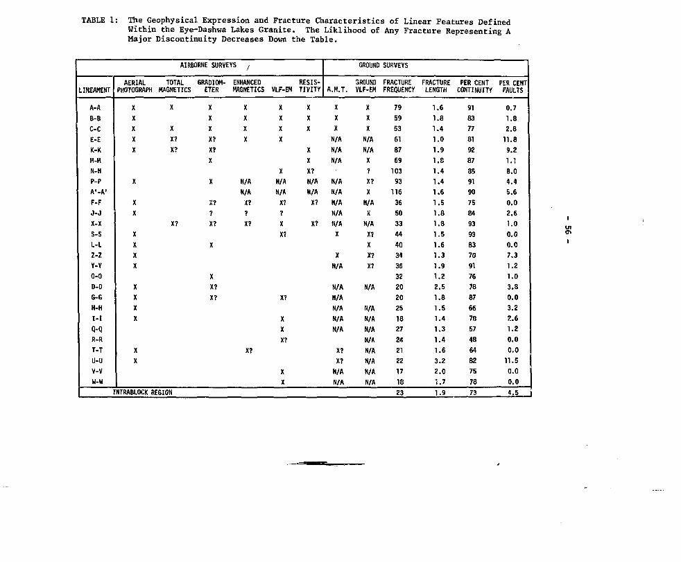
TABLE 1: The Geophysical Expression and Fracture Characteristics of Linear Features DefinedWithin the Eye-Dashwa Lakes Granite. The Liklihood of Any Fracture Representing AMajor Discontinuity Decreases Down the Table.
LINEAMENT
A-AΒ-B
C-CE-EK-KH-MN-H
P-PA'-A
1
F-FJ-JX-XS-SL-LZ-ZY-Y0-0
D-DG-GH-HI-I
Q-QR-RT-TU-UV-VW-U
AERIALPHOTOGRAPH
XXXXX
X
XX
XXXX
XXXX
XX
AIRBORNE SURVEYS ,
TOTALMAGNETICS
X
XX?X?
X?
INTRABLOCK REGION
GRADIOM-ETER
XXXX?X?X
X
X??X?
X
XX?X?
ENHANCEDMAGNETICS
XXXX
N/AN/A<??X?
X?
VLF-EM
XXXX
XN/AN/A
X??
XX?
X?
XXX?
XX
RESIS-TIVITY
XXX
XXX?N/AN/AX?
X?
A.M.T.
XXXN/AN/A
N/A
N/AN/AN/AN/AN/AX
XN/A
N/AN/AN/AN/AN/A
X?X?N/AN/A
GROUND
GROUNDVLF-EM
XXXN/AN/AX?X?XN/AXN/AX?XX?X?
N/A
H/AN/AN/AN/AN/AN/AN/AN/A
SURVEYS
FRACTUREFREQUENCY
79
59
53
61
87
69
103
93
116
36
50
33
44
40
34
36
32
20
20
25
18
27
24
21
22
17
18
23
FRACTURELENGTH
1.61.8
1.4
1.0
1.9
1.8
1.4
1.4
1.6
1.5
1.8
1.8
1.5
1.6
1.3
1.9
1.2
2.5
1.8
1.5
1.4
1.3
1.4
1.6
3.2
2.0
i.7
1.9
PER CENTCONTINUITY
91
83
77
81
92
87
35
91
90
75849393
83
70
91
76
78
87
66
78
57
48
64
82
757873
PER CENTFAULTS
0.7
1.8
2.8
11.8
9.2
1.1
8.0
4.4
5.6
0.0
2.6
1.0
0.0
0.0
7.3
1.2
1.0
3.8
0.0
3.2
2.6
1.20.0
0.0
11.5
0.0
0.0
4.5 i

- 57 -
PORE STRUCTURE PARAMETERS OF IGNEOUS CRYSTALLINE ROCKS- THEIR SIGNIFICANCE FOR POTENTIAL RADIONUCLIDE MIGRATION
T.J. KatsubeGeological Survey of Canada
Ottawa, Ontario
Nominally unfractured granitic rocks from Pinawa, Manitoba andAtikokan, Ontario, show background hydraulic conductivities in the order of10"10 to 10"9 cm/s (l). Since these conductivities are due to a complexnetwork of parallel and sequential paths created by microfractures, theradionuclide flow velocities would be small and be exceeded by diffusion.This is based on the assumption that the average hydraulic gradient would bein the order of 10"^ for a long period of time, such as 10^ to 2 x 10⁵ a.Pore structure will play an important role, not only in retarding the radio-nuclide diffusion rates through the nominally unfractured rock, but also insorbing the radionuclides and retarding the radionuclide flow along themajor fractures, and in storing the radionuclides within the rock-formingcrystals. The ability to retard radionuclide migration through theunfractured rock, the ability to sorb and retard the radionuclides infractures, and the ability to store the radionuclides constitute the"isolation capacity concept". The purpose of this paper is to propose someparameters that may be used to compare rocks in terms of their isolationcapacity.
Rock texture has a significant effect on pore structure. Pores canbe divided into several categories as shown in Figure 1. Petrographicalstudies by means of microscope and scanning electron microscope (SEM)suggest that most of the potential porosity is in plagiociase grains, whilea large portion of the connecting porosity is related to the quartz grains.Alteration has a significant effect on pore structure in various ways.There are indications that alteration in granite increases the quantity ofavailable porosity, but decreases the amount of connecting porosity.
The porosities of core samples from various depths and boreholesare currently being determined in the laboratory. A number of methods isavailable for determining the subsurface three-dimensional distribution ofthe porosities. One method uses the established relationship betweenporosity and rock type together with the extensive geological informationgathered from the field studies. Another method employs the subsurface andborehole geophysical data. In principle, the latter should provide a moreaccurate picture of the porosity distribution. However, the capability ofgeophysical methods for use in igneous crystalline rocks is not yet fullyknown, and since the effect of rock type on the porosities seems to besignificant, the former method is used to determine the porosity distribu-tion.
One of the first steps to be taken to evaluate the isolationcapacity of a rock mass is to determine the three porosities (connecting,available and potential porosities) in the laboratory and then use thegeological information to determine the three-dimensional subsurface dis-tribution in the rock mass.

- 58 -
REFERENCE
T.J. Katsube, "Pore Structure and Pore Parameters that Control the Radio-nuclide Transport in Crystalline Rocks". Proceedings of the TechnicalProgram, International Powder and Bulk Solids Handling and Processing,Rosemont, 111., May 12-24 (198l) pp 393-*»O9.
•«'
cCONNECTING POROSITY
BLIND POROSITY
RESIDUAL POROSITY
AVAILABLE POROSITY
POTEINTIAL POROSITY
Figure 1: Model of pores in igneous crystalline rock

- 59 -
PERMEABILITY ASSESSMENT OF THE NEAR-EXCAVATION ZONE
A.T. Jakubick * and V. deKorompay +* Ontario Hydro, Toronto, Ontario
+ Beaconsfield, Quebec
The near-excavation zone of underground openings has an increasedfracturation index. When isolation of the underground space is required,these fractures represent a potential shortcut for migrating substances.
A new method was designed for detection of very tight fissures inthe near-wall zone and measurement of their spacing, orientation andaperture. The method uses boreholes plugged off by special packers andevacuated at constant rate until a characteristic steady state pressureis achieved* The loss-of-vacuum dependence on time and air flow arerecorded. The essential conditions for a proper test are: (1) no leaksin the system, (2) knowledge of the temperature in the test section,(3) knowledge of the compressibility and viscosity of the air,(4) knowledge of the compressibility of the rock. It must also be takeninto account that the permeability of rock to a gas is a function of theabsolute pressure of the gas. In particular, as the absolute pressure ofthe gas increases, the apparent permeability of the rock decreasesasymptotically to the so-called "liquid permeability for a gas"(Klinkenberg slip)• The hydraulic conductivity for other fluids can bederived by giving due consideration to density and viscosity of thespecified fluid. The thickness of the tested zone may extend from 25 cmto 15 m.
j
The conventional analysis for such tests assumes that the rock isan isotropic porous permeable medium through which flow occurs radiallyto the borehole. The rock is then described in terms of permeability andspecific storage. For crystalline rocks the interpretation is in termsof fissure frequency and average aperture. The flow through fissures isassumed to be a function of the cube of the aperture. However, the testin fact measures transmissivity and storage. To test these assumption,in situ measurements were performed in two uranium mines in Elliot Lake.A series of shallow holes was drilled in the roof according to apredesigned grid. By use of a straddle packer system the location of thefractures was estimated. Previous observations on cores indicated anorder of magnitude larger number of fractures than actually found. Thetests proved the high sensitivity and good reproducibility of the newfracture detection method. The rock matrix to fractures permeabilityratio was 10~8 to 10~9. However, injection tests in the sameboreholes showed that the fracture apertures are not constant and dependon the test pressure conditions and rock. Investigation of the pressureand temperature dependence of the rock in laboratory is planned toquantify these effects. Areas of use of the new near-surfacepermeability assessment method are: Identification of potential leakagesin a geologic repository; Fracture detection for effective rock boltingin underground excavations and tunnels; Measurement of groutingeffectiveness; Monitoring the concrete wall permeability of vacuumbuildings.

- 60 -
INFLUENCE OF HEAT FLOH ON DRIFT CLOSURE DURING CLIMAX GRANITE SPENTFUEL TEST: CALCULATIONS AND MEASUREMENTS*
T.R. Butkovich, J.L. Yow Jr. and O.N. MontanLawrence Livermore National Laboratory
Livermore, California, USA
An underground installation in Climuc granite was constructed at theU.S. Department: of Energy's Nevada Test Site to evaluate granite as ageological medium for deep storage of high level nuclear reactor waste.Spent fuel aEiSEStiblies from an operating nuclear reactor were emolaced in adrift 420 m below the surface during the spring of 1980. This drift, checentral of three parallel drifts spaced on 10 m centers, was provided withseventeen storage holes in the floor on 3 m centers. Eleven spent fuelcanisters and six thermally identical electrical simulators were emplacedin these holes. Electrical resistance heaters were also installed invertical holes in the floor of the side drifts on 6 m centers. The thermaloutput of the side drift heaters is being adjusted periodically to simulatethe thermal response of a large storage array.
Temperatures are being measured continuously during the projected5-year storage period. Nearly 500 thermocouples were emplaced at variouspoints near tie spent fuel canisters and at. various distances from theopenings in the rock. Measurements of drift deformation have been maderoutinely since about 6 weeks after emplacement of the spent fuel. Bothvertical and norizontal closures are being measured at five locations alongthe side dri'/ts and at six locations along 'the central drift. Two types ofinstrumentation are being used: convergence wire extensometers which arerecorded automatically and a manually operated tape extensometer with whichmeasurements are taken periodically. Corrections to the data are made toaccount for temperature and mechanical effects. Redundant measurementsshow them to be repeatable to within t 0.1 mi. At this time, about twoyears of data have been collected, which is sufficient to compare withcalculations made during the early stages of the experiment.
Finite element calculations were made using as-built drift geometryand measured physical, mechanical, and thermeil properties of the Climaxgranite. The ADINA structural analysis and the compatible ADINAT heat flowcodes were chosen for this study because of their capability to handle heatflow, by conduction, radiation, and convection, thermoelasticity,excavation, and the relative ease with which new models may be added tohandle the effects of jointing in the rock. It was necessary to adaptADINAT to model internal radiative heat transport within the drifts and theeffects of ventilation during the experiment.
* Work performed under the auspices of the U.S. Department of Energy by theLawrence Livermore National Laboratory under contract number W-7405-ENG-48.

- 61 -
An ADINAT calculation was made using temperature-dependent thermalconductivity measured on Climax granite* The calculation included thedecaying spent fuel heat source below the floor of the central drift andthe prescribed periodic adjustment of the electric heaters in the floor ofthe side drifts. The calculation also included the radiative heat transferwithin the drifts and the removal of heat by ventilation of the drifts.ADINAT produces nodal point temperature histories which then drive theADINA thermomechanical model.
Values of the elastic modulus of Climax granite measured in the fieldand in the laboratory are quite different. Laboratory measurements onsmall samples given an average of 48 GPa, while values obtained in thefield using different measurement techniques in the rock mass resulted inan average effective modulus of about 27 GPa. Therefore, two separateADINA calculations were run; one with the laboratory measured modulus, andthe other with the field determined value. Temperature dependent thensalexpansion coefficients obtained from measurements made on Climax granitesamples were also used. The pre-existing stress field was inputted basedon measurements of principal stresses made at the Climax site.
Temperature data have been compared with calculations for the timessince the emplacement of the spent fuel canisters. Since the calculationswere two-dimensional, temperature measurement stations near the centralportion of the drifts were selected for this comparison. Agreement betweentemperature change data and calculations are in the 5 percent range for 38stations that lie near the center of the drifts.
The calculated closure for the tunnels is smallest for the stifferlaboratory measured modulus and a factor of 2-3 times larger for the fielddetermined modulus. Closure of the drifts plotted as a function of time isparallel for both calculations. The calculated vertical closure of thecentral drift and the horizontal closure of the side drifts shows most ofthe deformation occurring early, with the maximum at about 6 months afterstart-up, followed by a reversal of slope and a slight gradual reopening.Wie calculated horizontal closure of the central drift and the verticalclosure of the side drifts are similar in that most of the closure occursearly, but in these cases the closures continue at a much slower ratewithout reversal.
The calculation using the modulus from the field determinationproduces the best agreement with closure data. Although the tapeextensometer measurements missed the first 6 weeks of closure, thecalculated results track the measurements. A mean curve through all thedata points roughly parallels the calculated curves, and where a slopereversal is calculated, the measurements show an actual reversal of slope.The difference between measurement and calculations in each case is within20 percent of the measured value, with the magnitudes of closure being asmuch as 3 i&m.
The agreement between measurements and calculations of both thetemperature fields and tunnel closure is gratifying. The closure resultssuggest that even better agreement might be obtained with a calculationusing a somewhat large modulus.

- 62 -
IN SITU PERMEABILITY AND HEATER TESTS ON HLW DISPOSALTECHNOLOGY DEVELOPMENTS IN JAPAN
Kazuhiko Maekawa*, Takaaki Kashiwagi* and Naomi Tsunoda+
^Mitsubishi Metal CorporationTokyo, Japan
''Tower Reactor and Nuclear Fuel Development CorporationTokyo, Japan
In Japan, for the purpose of the trial disposal of high level waste(HLW) starting in 2015 "Research for Potential Geological Formation" is beingpromoted. As a part of the research, the Power Reactor and Nuclear FuelDevelopment Corporation (PNC) started in situ tests in 1980. This is a pre- .liminary report of the results of these tests. In situ tests in Japan stillstay on the first step, and the purposes of the tests are as follows.
1. Establishment of the test method for permeability in rock masses.
2. Establishment of the test method for thermal conductivity in rock masses.
3. Comparison of in situ test data with laboratory test data.
In situ tests are carried out both in the hard rock test facility andin the soft rock test facility. The former is set up at the Shimokawa Minein northern Japan and the latter is set up at the Hosokura Mine in north-eastern Japan. The Shimokawa Mine is an operating copper mine and its hostrock is diabase (one kind of basaltic rock). The Hosokura Mine is an operat-ing lead and zinc mine and its host rock is tuff. Both mines are not apotential disposal site but were selected for in situ test sites. The loca-tion of both mines is shown in Figure 1.
SHIMOKAWA PROJECT
The test period of the Shimokawa Project is scheduled for three yearsstarting in 1980. The test program includes the following:
1. Investigation of the geological data of the rock mass.
2. Permeability test of the rock mass.
3. Heater test of the rock mass.
4. Permeability test of the hot rock mass.
5. Migration test.
6. Evaluation test on the efficacy of the grouting.
At present tests 1 to U have been completed.

- 63 -
The permeability test was designed to simulate the large-scale permea-bility test at the Stripa Mine. Permeability of the rock mass was determinedas 2.44 E-6 cm/s. The design of the heater test is shown in Figure 2. Twoheaters were installed in two boreholes which were 322 mm in diameter and 2 mapart. Each heater (276 mm diameter, 1500 mm length) generated 0 to 15 kWelectric power, and maximum permissible temperature was 500°C. Around theheater holes twelve boreholes were drilled, and forty thermocouples and twosets of strain gages were installed. Two heaters were set to generate 2.7 kWeach for one month, and the temperature. and stress in the rock mass weremeasured. The in situ thermal conductivity seemed to be 60% larger than thatmeasured in the laboratory. Migration tests will be started in 1982. Fluo-rescein and non-radioactive strontium ions will be used for the tracer.
HOSOKURA PROJECT
The Hosokura Project was started in the last year and it will be con-tinued for over three years. The test program is similar to that of theShimokawa Project.
Now that both projects are on the way, although we have not obtainedenough data at present, we expect useful results from now on.

- 64 -
SHIMOKAWA NINE
30m
45*
Figure 1 The Location of In Situ Test Facilities in Japan

- 65 -
HORIZONTAL SECTION
A "
B' CJ I .
HEATER CONTROLL BOARD
B*9
B4 BH
• • o • • o • • •B l B2IIIB& B7 HZ HI" III) BI2
B 3 B 6
VERTICAL SECTION
B - B 'B3 HI B4
scale I/IOO
I.Um.
fC
Α - A 'B1B2WB5B7 H2 BIO Bl 1 B12
0 H 1 . H 2 : HEATER HOLE
• B 1 - B 1 2 : MEASURED HOLE
C - CBβ B7 B8 B9
: TEST HOLE
: HEATER
: THERMOCOUPLE
: STRAIN GAGE
Figure 2 The Design of Heater Test

- 66 -
DESIGN AND CONSTRUCTION OF EXPLORATORY SHAFTSFOR UNDERGROUND NUCLEAR WASTE STORAGE
P.K. Frobenius and C.L. WuBechtel National, Inc.San Francisco, CA, U.S.A.
The Waste Isolation Pilot Plant (WIPP) program is intended to developand operate a research and development facility for the demonstration of thesafe disposal of defense related radioactive wastes. The full WIPP facilityconsists of surface structures which receive and process wastes, four shaftsand a network of underground drifts in salt for transportation and storageof the wastes as well as conducting waste experiments.
Concurrant with the full WIPP design, a site preliminary design andvalidation program (SPDV) is currently under design and construction. Theobjective of the SPDV program is to confirm the geologic adequacy of the site,to verify the engineering properties of the salt at depth, and to verify thedesign of the underground facility. Two shafts and underground test roomswill be instrumented to evaluate the stability of underground openings and tomeasure rock responses. In addition, various experiments to observe simulatedwaste and waste package performance under disposal conditions will be con-ducted in the underground test rooms for a period of up to five years.
The SPDV program includes design and construction of two vertical shaftsto a depth of 660 meters (2,160 feet) which is approximately to the middle ofthe Salado formation, a 900 meter (3,000 foot) thick salt bed. Both shaftshave been constructed by the downhole drilling technique. The exploratoryshaft was first drilled to a 3.66 meter (12 foot) diameter hole using a largedrilling rig with brine as the reverse circulation drilling fluid. The 3.05meter (10 foot) diameter steel liner sections were welded together as theliner was lowered down the hole to the top of the salt formation which is about250 meters (820 feet) below the ground surface. Then concrete grout was placedin the annulus between the liner and the rock wall. A reinforced concrete keywill be constructed right below the liner at the rock-salt interface. Chemi-cal seal rings will be installed in the key to stop any potential water migra-tion into the shaft. The lower portion of the shaft in the salt formationwill not be lined. Wire mesh and rock bolts will be installed as required tosecure the shaft. Steel buntons will be provided in the shaft to supporttimber guides for the salt skip. In the unlined portion of the shaft, thebunton to salt connections are designed to accommodate salt creep during theoperating life of the facility. On the surface, a headframe and ground mounteddrum hoist system are designed for transporting the excavated salt during theunderground test room construction, and for eventual SPDV test operationsunderground.
The second shaft is a 1.83 meter (6 foot) diameter ventilation shaft.During SPDV this unlined shaft will also be used for geological logging, andas a second egress for the stand-by emergency hoist to go down for rescue oper-ation if needed. When the full WIPP facility is under construction, thisshaft will be enlarged to the 5.79 meter (19 foot) diameter waste shaft througha slashing operation.

- 67 -
Geotechnical instrumentation including piezometers, earth pressurecells, strain gauges, extensometers and stressmeters will be installed in theshafts, behind the shaft key and in the test rooms. These instruments are de-signed to monitor the shaft convergence and room response for determinationof rock salt properties, to monitor the structural changes in rooms under con-ditions that simulate the effects of experiments with heat-producing waste,and to monitor the potential build up of hydrostatic pressure on the linedportion of the shaft. The sensors are designed for both local and remotereadout, and signal outputs are compatible with a central data acquisitionsystem.
As part of the site validation program, geologic conditions within andadjacent to the test and storage horizon will be investigated through a hori-zontal drilling program. At the underground storage level, three horizontalcore drillings have been planned to cover the storage area of the full WIPPfacility. These holes will extend 600 to 900 meters (2,000 to 3,000 feet) toobtain cores for examination and testing and to explore for fluid inclusionand geologic structural anomalies. These samples will also be compared withthose obtained previously from the surface drilling.
The SPDV construction commenced in April of 1981, starting with sitegrading, fencing and construction of the drilling fluid pond. The drilling ofthe exploratory shaft started in July 1981, and was completed in December,1981. Plumbness of the shaft was monitored during drilling by the use of amulti-shot Sperry Sun gyroscope survey. After the steel liner was loweredinto the exploratory shaft and cemented in place with grout, the drill rigwas moved to the ventilation shaft location. Drilling of the ventilationshaft is now complete and the contractor is preparing to place concrete forthe exploratory shaft key and to outfit the shafts.

- 68 -
CONSIDERATIONS IN THE DESIGN OF HIGH-LEVEL WASTEREPOSITORIES IN CRYSTALLINE ROCKS.
J.A. ALLISON B.Tech. MSc. MICE. MIMM. FGS.L.M. LAKE BSc. MSc. DIC. PhD. MICE. MIMM. FGS.
Mott, Hay & Anderson, Consulting Engineers, Croydon, England.
Crystalline rocks possess several attributes which favour theirselection as host media for the isolation of high-level wastes in deepunderground repositories. However, the influence of naturaldiscontinuities dominates performance, particularly quantities and ratesof groundwater flow, which cannot presently be predicted to an accuracybetter than one or two orders of magnitude (3,4).
Under these circumstances, it is appropriate to examine thosefactors over which engineering control may be exercised. If these canbe optimised, safety analyses should indicate whether current marginsof uncertainty with respect to the performance of the host rock are ofmaterial concern.
Repository excavations are themselves potential direct preferentialflowpaths to the biosphere and may link otherwise unconnecteddiscontinuities in the host rock (2). By implication, the number andsize of shafts and tunnels should be reduced to a minimum and theorientation of tunnels should be disposed so as to intersect discontinuitysets at a minimum frequency (3). These basic precepts are not generallyreflected in current international conceptual design proposals, wheregeometries are often arbitrarily defined and shafts and tunnels areduplicated to allow concurrent construction and emplacement.
The excellent stand-up time characteristics of crystalline rocksmay be used to advantage by completing all construction and validationtests well in advance, involving the use of only one or two shafts andaccess tunnels. Other engineering expedients such as the use of 'compact'ventilation systems involving ducted compressed air, possibly withrefrigeration, can also assist in the reduction of excavation sizes (1).
Other important precepts are often pre-determined largely bylogistical or technical requirements within the wider context of wastemanagement policy. These include :
- canister size and shapethickness of overpacks (if any)
- period of interim storage
Engineering and cost optimisation studies may be used to examine theimportance of these parameters in relation to the design size and emplace-ment configuration within a repository and the overall costs of packaging,

- 69 -
storage and disposal. An analysis is presented for a simple repositorymodel at a nominal depth of 1000m in crystalline rock. The heat outputcharacteristics of the waste units are assumed to correspond to a meanof Magnox and PWR vitrified wastes comprising 15% by weight of fissionproducts and the maximum allowable heat flux at the surface of theemplacement holes is taken as 212 W/m2; varying these assumptionshowever, does not materially alter the conclusions.
Twelve different waste units are considered, based on four alternativecanister sizes with three different thicknesses of cast steel overpack.Emplacement: hole depths are varied from 6 m (single unit in each hole) to300 m (multiple emplacement systems). Interim cooling periods are variedfrom the minimum compatible with the surface heat flux constraintincorporated in the model to an upper limit of 120 years.
Detailed results of the engineering optimisation of these variablesare represented on a series of graphs of repository size versus period ofinterim storage for each waste unit/emplacement hole depth combination.Results of the cost optimisation are presented in table 1.
Several important trends emerge from these optimisations, and resultssuggest that a waste unit approximately 0.75 m in diameter and 1.25 m inheight, with a 100 mm thick overpack, offers greatest advantages in termsof repository engineering design and cost effectiveness. Two options areavailable for the design of compact and economic repository facilities basedon this waste form, both of which are compatible in terms of overall costs.These are :
interim storage for about 60 years followed by the emplacement in acuboidal configuration, with hole depths of about 50 m.
interim storage for about 100 years followed by emplacement in arelatively close-packed planar array, possibly using pre-fonned holesin concrete-filled trenches, constructed in the tunnels.
The latter is preferred since it provides considerably greaterengineering control and avoids difficulties associated with the blind drillingof large diameter emplacement holes.
Recent international repository design studies have been based uponprecepts established during the past decade by nuclear scientists. Thesehave included rather idealised assumptions concerning the host rock, otherparametric constraints being determined by reference to pre-disposalstrategies developed without full regard to their underground engineeringimplications. The study shows that greater emphasis must be placed oncontrolled engineered barriers to account for the properties of real groundand the practicalities of construction (2). The broader engineeringapproach described indicates a more satisfactory basis for repository designdevelopment.

- 70 -
REFERENCES
(1) J.A. Allison and L.M. Lake, 'A Review and Synthesis of InternationalProposals for the Disposal of High-level Radioactive Wastes intoCrystalline Rock Formations', Mott, Hay & Anderson, Report 177 (1981).
(2) J.A. Allison and L.M. Lake, 'The Backfilling and Sealing of RadioactiveWaste Repositories', Mott, Hay & Anderson, Report 249 (in preparation).
(3) J.A. Hudson and S.D. Priest, 'Discontinuities and Rock Mass Geometry'.Int. J. Rock Mech. & Min. Sci., Vol.16, No.6(1979).
(4) A. Runchal and T. Maini, 'The Impact of a High-level Nuclear WasteRepository on the Regional Groundwater Flow', Int. J. Rock Mech. &Min. Sci,, Vol.17, No.5 (1980).

TABLE 1 COST OPTIMISATION STUDY; COMPARISON OF COSTS FOR ALL OPTIONS
PERIOD OF
INTERIM
STORAGE
Hltim to Mtliry•iirrut htat fluxcrlttrioa «• themon Titli 16.
30 Y.«tj\TMt 17)
63 Tnr i(T«bl« IS)
90 T u n(r«bi. 13)
EMPLACEMENT
CONFIGURATION
Fltjur
CboKUl (SO a)
CiboKlal (100 •)
Cmboidal (300 •)
Nuu
CboliWl (50 a)
Cubotdtl (100 c)
CtboMal (300 •)
Pliatr
Cuteldal (SO •)
Caboidal (100 •)
CaboldU (300 •)
Pluar
OiboUU (50 >)
CuMlbl (.00 a)
CutMad (330 a)
TOTAL COST FOR EACH WASTE UNIT TYPE IN £ MILLION( PERCENTAGE OVERPACK COSTS INDICATED IN BRACKETSI
CANISTER TYPE Iα)
1
-
556
204
125
74
342
194
126
»9
254
179
135
•06
2
71!(•*)
294-(22*)
!»•(34)
130"(50«
33"(17*)
248(:<*)
183(3»)
144(««)
289(2*)236
(2W)189
(34*)i<0
(41*)
258(25S)
237(2«)
202
178(37«
3
1.132(31*)
K9(53«
S35(<7«
45<(7»*)
»16(58*)
559(64«)
504(71«
474(75*!
571(CM)
536(««)
504(71*1
4B7(73*1
575(fM)
53'(67*)
517(69*)
505(V0»)
CANISTER TYPE(b)
1,
-
548
i l l
123
70
342
ISC
123
84
241
•75
•le
100
5
65!"()*)
257*(2!*)
171*(31*)
U41
(5«)
371(154)
232(24*)
IK(341)
12s(44J)
262(201)219
(26f)
177(3»)
144
(39*)
234( 2 4 )
21J
(26«)
193!31»)
14'(35*1
6
980(27*)
SOS(52*1
409(65*)
344(77*)
CI 4
(SS)436
(60*1
393(67*)
365(73*1
46a(57*)
430(62*)
400(66«)
332(69*)
46S(5«>
425(6»)
41C<6,<)
4C(»«)
CANISTER TYPE (c|
7
-
-
-
157
109
93
63
8
-
-
Iβ:
(!•'*)
I2£
(J2»)
105
(!7«
J4(30*1
:6S(1»>
13"(20*)
12"*
(2]()
114
(25*)
9
382
(34*)
237
(55<)
202( 6 4 )
181(72*)
310(42*)
231(56t)
204(630
189(69*)
269(•8*)
23«(S4»
219(590
209
(62*1
26;
(491)
S51
(5*)
!37(55»)
229(57*)
CANISTER TYPE (d)
10
1
1
1
1
-
184
103
79
('
154
115
9:
94
11
-
-
178(13O
122(18*)
101(28*)
89(2»«)
158(14*)
133(17*)
118(19*1
109(21«)
12
313
(31*)
191
(52*)
166
(59*)
148
(67*)
268(37«
190(5M)
l<9(5>O
155
(«4*)
23i(41()
200
(s°o184
(5<O
17'
(570
145
(•0*1
214
(«*)
202(49«)
195(51*)
I•0
* Con or -.attrla itor«i« riellltlc4 ao'. Ioclud4d

mm-
- 72 -
ENGINEERING ASPECTS OF GEOLOGICAL WASTE ISOLATION
Lawrence A. White* and David L. Pentz+Golder Associates (U.S.A.)
* Washington, D.C+ Bellevue, Washington
INTRODUCTION
This paper contains specific reference to high-level radioactivewaste. However, many aspects of the concepts presented are equallyapplicable to other types of waste including low-level radioactive waste,uranium mill tailings, and hazardous waste in general.
In this paper, the authors propose concepts for furthering theengineering of the disposal of high level radioactive waste in minedcavities.
It is the intent of the authors to stimulate discussion on where togo from here. The U.S. Nuclear Regulatory Commission's proposed rule,10 CFR Fart 60, has served an important function in the U.S. program instimulating research and development on alternative waste forms andengineering barriers (1, 2). However, to some, the proposed rule alreadyappears outdated in being too emphatic on what are minimum requirements ofthe engineered system. Also to others, this even seems contradictory tothe system approach as originally conceived by the U.S. Interagency ReviewGroup (3). Unless further guidelines evolve, we may run the risk ofblindly trading one set of uncertainties for another, stifling innovationin design, and escalating cost.
SUMMARY
An essential part of the engineering process as it applies togeologic repositories includes:
1. Ascertaining where there are uncertainties, either in thecharacterization of the system or in the estimate of systemperformance;
2. Estimating the degree of those uncertainties in the areasidentified, and quantifying them to the degree practical, evenif this process is subjective in part or whole.
3. Reducing uncertainties through the prudent choice of anexploration and testing program ft each stage of the developmentprocess (Figure 1 shows how those uncertainties are reduced ateach step).

•r
- 73 -
6.
Anticipating residual uncertainties likely to remain long afterclosure of a repository due to practical limitations, usingengineering judgements;
Development of practical and cost effective solutions fordealing with residual uncertainties without being undulyrestrictive or conservative; and
Evaluation of solutions through testing and observation duringsite characterization, construction and facility operation.
Special Considerations
There are several aspects of the repository development process thatare unique and which affect the engineer's perception of uncertainties thatmust be dealt with. These considerations include:
1. The inability, due to time scale, to demonstrate performancewith certainty. Thus, the classical observational approach usedby engineers can only be carried out partially and can only beused for some elements of the repository system. On the otherhand, the likelihood of system performance falling withincertain limits of the sytem can be estimated.
2. Many aspects of the technologies involved have been establishedbut experience is limited. Thus, the designers of repositoriesmust draw on experience in other applications of thosetechnologies. An added dimension to this problem is thatsometimes when we couple known but different technologies in anew way, the constructed system very often does not initiallyperform as expected.
3. No matter how much effort is expended, it will be imposssible toknow everything we would like about the site selected. On theone hand there is a clear desire to know more about the sitethan for any other type of underground structure, but on theother hand, there are restrictions imposed by existinginvestigational tools and also by the need to limit subsurfacepenetrations.
An Engineering Approach
The problem at hand is coming to grips with the specific issues anduncertainties centered around the relatively few alternative sites andcomplementary conceptual designs under consideration for the firstgeneration geologic repository. Thus, the focus of engineering efforts canshift to a more narrow scope of issues on uncertainties that need to beaddressed and the specifics of how to deal with them.

•J
- 74 -
The; following approach is recommended in progressing to the nextstage in the repository development process.
1. Seducing Uncertainties
The ability to engineer a facility to fit site conditions and tocompensate for known uncertainties regarding site performanceshould be a major factor in the final choice of a site. Thesite characterization process leading to the selection of afinal site, the design of the facility, and then construction,should be aimed at reducing uncertainties in predicting overallsystem performance.
2. Acceptable Level of Residual uncertainty
unfortunately, most performance standards that are needed forengineering do not include any statement of what constitutesreasonable proof of performance. It is the authors' belief thatprobabilistic or risk assessment approaches will gain strongersupport in the near future as a way of dealing with thisproblem. Such standards, for example, could be specified interms of a probability distribution where "a minimum performancelimit" and some level of confidence that the performance willnot fall below this specified level is given (Figure 2).
Site and Design Specific issues
An important part of the engineering process should be to scopeout and quantify the residual uncertainties centering aroundalternative design concepts. We want to be sure we are notsubstituting one set of uncertainties for another. This part ofthe design process is relatively new to the engineer, but willbe necessary to deal with the geologic w»ste disposal problem.He must determine not only what we know but also what we don'tknow to the degree practicable.
Practical Solutions
How difficult it will be to develop practical solutions to dealwith specific issues will depend on (1) the characteristics ofthe waste (e.g., toxicity, hazardous life, chemistry of wasteincluding solubility, and volume), and (2) the characteristicsof the site. The engineering of practical solutions willinclude the following steps:

m
- 75 -
The Development of a Conceptual Design of the Waste DisposalSystem. This will include conceptual processes to alter thewaste form so that it is more suitable for disposal at thesite under consideration. It will also include establishingthe layout, configuration, and shape of the undergroundexcavation and the design of the engineered barriers system.It can also include operating decisions - ventilating wasteheat, delaying backfilling, or decisions ti. t preserveoptions and maintain flexibility.
The Detailed Design of the Engineered Barrier System.This can include the details such as the selection ofmaterials, dimensions, and the development of constructionand operating procedures.
A program of testing and evaluation that will begin with thesite characterization process and be carried through toclosure of the waste disposal facility. The objective is toselect alternatives that optimize performance and confidencein such performance at reasonable cost. In the early stagesconceptual design concepts will be tested, and as theflexibility of design decisions become more and morerestricted, more detailed aspects of design will be tested.
REFERENCES
1. L.A. White, H.J. Bell, and D.H. Rohrer, Regulation of GeologicRespositories for the Disposal of High-Level Radioactive Wastes, 2ndAnnual Symposium on the Scientific Basis for Nuclear WasteManagements, Materials Research Society, Boston, Massachusetts,U.S.A., 1979.
2. L.A. White, Geologic Disposal of High-Level Radioactive Waste,Association of Engineering Geologists, Annual Convention, Dallas,Texas, U.S.A., 1980.
3. IRQ, Report to the President by Interagency Review Group on NuclearWaste Management, NTIS, Springfield, Virginia, U.S.A., 1979.

r
- 76 -
UNCERTAINTIES Figure 1
1.0
© c
!
4
H-3
£ •
I!© C
Acceptable Proof
Acceptable Range
Minimum Acceptable Level ofKnowledge/Uncertainty Over Time
Unacceptable RangeTime
• i t * ••lection *Characterization
< • *inSitu Taatlng RepositoryConstruction
SinSio<
• Repository• # Operation
3 *
Decommissioning
c
•Mer Associates

f
- 77 -
PERFORMANCE CRITERIA Figure 2
- •a.
t Expected performance . £ P, •;
-A-Performance limit,xc
Acceptableperformance:
roba
b
bounded •x%*more than^a NlVlff ftllCMI
o a specifiedas (percentage= of total
Performance measure, x
Where: x is the radionuclide release rate integrated at aspecified boundary such as the accessible environment.
A is the difference between the estimated expected performanceand specified performance limit. The larger the uncertainty (varianceor std.dev.)the better the estimated performances must be so as tosatisfy standard for acceptable performance.

•J- 78 -
THE USB OF URANIUM-SERIES DISEQUILIBRIUM TO DETERMINE RADIONUCLIDEMIGRATION ON GEOLOGIC TIME SCALES
M. GascoyneAtomic Energy of Canada Limited
Whiteshell Nuclear Research EstablishmentPinawa, Manitoba
This paper describes the use of uranium-series disequilibrium studiesof crystalline rocks to determine the mobility of actinide and daughterelements in natural rock systems, and to estimate the time interval duringwhich migration occurs.
Several intermediate radionuclides in the U-238, U-235 and Th-232 decayseries have half-livea of sufficient duration to permit measureable fraction-ation to occur in geologic and hydrologic processes. In a closed system,these nuclides attain radioactive equilibrium with one another after about 2.5Ma (approximately ten half-lives of the longest lived member of the decayseries). However, their different physical and chemical properties allow themto fractionate in rock systems that are open to penetration by gases orliquids. Detection of radioactive disequilibrium between any parent-daughterpair in a geologic sample not only indicates migration of one or other of thepair, but describes the time interval in which it has occurred. This intervalis determined solely by the half-life of the daughter nuclide, e.g. U-238-U-234, up to 2.5 Ma; U-234-Th-23O, up to 750 ka; Th-230-Ra-226, up to 16 ka.In practice, the precision of measurement of these radioactivity ratios limitsthe extent of each method to about half of these ranges. Typical usefulranges are shown in Fig. 1 for several parent-daughter pairs of U- andTh-series nuclides.
Results have been obtained for application of the U-seriee dis-equilibrium technique to granitic cores from the Eye-rDashwa Lakes pluton, nearAtikokan. northwestern Ontario. The detailed geology of this pluton andsequence of fracture-filling evente have recently been described by Kamineniand Brown . Samples of whole rock and fracture-filling minerals from corestaken to 1100 m depth have been analysed for U-238, U-234, Th-232, Th-230,Th-228 and Ra-226 using alpha-apike isotope dilution analysis and Rn-222scintillation counting . The results show:
1) (U-234)/(U-238) ratios of whole rock and mineral samples lie between about0.85 and 1.0, suggesting that most samples have lost some U-234 (or, lesslikely, gained U-238) during the last 2 Ma.
2) (Th-230)/(U-234) ratios lie close to equilibrium, although they show morescatter than (U-234)/(U-238) ratios. This is partly due to the greateranalytical uncertainty caused by lower Th yields in the chemicalextraction process and partly by statistical uncertainties in calibrationof the mixed Th-U tracer.
3) (Ra-226)/(Th-230) ratios are also close to unity for all samples except anintensely altered and fractured portion of core ATK 2 at about -94 m,where the ratio is 3lightly greater than two.

J- 79 -
The depletion of U-234, yet with maintenance of radioactive equili-brium between U-234 and Th-230f initially suggests that U-234 was lost fromthe rock system over 350 ka ago, and since that time, gradual return toequilibrium has taken place with no further radionuclide migration. Thisinterpretation might be correct if U-234 loss was occurring purely by dis-solution from the solid phase, some time after formation from U-238. However,it may also be argued that the depletion is due to a slow, but continuous,U-234 loss up to the present, occurring mainly by recoil out of the crystallattice, into solution, during alpha decay of U-238 (this mechanism isgenerally considered to be the cause of U-234 excess in groundwaters and U-234depletion in sediments and weathered rocks ).
The observation of equilibrium between U-234 and Th-230 may then beexplained by the fact that U-234 loss occurs immediately on formation, and soTh-230 ingrowth will only attain the activity of the U-234 remaining in therock, and not that of the U-238. This 'steady-state' situation is more feas-ible from a geological and geochemical standpoint because it is difficult toenvisage a process that would selectively remove U-234 to such an extent,between 350 ka and 1 Ma ago.
The general condition of equilibrium between Ra-226 and Th-230 in-dicates that migration of these radionuclides has been negligible over thelast 8 ka. However, the Ra-226 excess in core ATK-2 indicates either Ra-226addition or Th-230 loss within this period, probably due to precipitationfrom, or dissolution by, groundwater at this depth. The exact mechanism couldbe better resolved by analysis of the state of equilibrium between thedaughter nuclides of Ra-226.
Although the interpretation of these results is tentative at present,this study generally indicates that migration of naturally occurring radio-nuclides is a slow process on a geological time scale, even in a well-fractured granitic pluton such as the Atikokan site. The depletion of U-234in whole rock and fracture-filling minerals is consistent with U-234enrichment in granite groundwaters observed in other regions, and suggeststhat direct recoil into the aqueous phase may be the dominant mechanism formigration, rather than simple dissolution of the solid phase.
REFERENCES
1. D.C. Kamineni and P.A. Brown, "A Preliminary Report on the Petrologyand Fracture Fillings of the Bye-Dashwa Lakes Pluton, Atikokan,Northwestern Ontario". AECL-TR-123, Available from SDDO, Chalk River,Ontario KOJ 1J0.
2. M. Gfascoyne, "Analytical Techniques for the Determinatiion of U-Th-RaIsotopic Ratios in Granitic Rocks". Techn. Memo. Geology Dept.McMaster Univ., Hamilton, Ontario, in preparation.
3. J.K. Osmond and J.B. Cowart, "2he Theory and Uses of Natural IsotopicVariations in Hydrology", Atomic Energy Rev. U_ (1976) 621-679.

7- 80 -
IO10
IO y
I0 8
I 0 7
io6
UL
iij 10
<
X io3
10
T r. I r
238,,j^ U series
m 235U series
i I
,232Th
A2 3 8 U
232235
Th seriesU
l-5xl06y
82 83 84 85 86 87 88 89 90 91 92 93ATOMIC NUMBER
Figure 1 Uranium and thorium decay series showing intermediate
radionuclides of geologic significance.

- 81 -
CHARACTERIZATION OP LOW LEVEL RADIOACTIVEWASTE IN CANADA
Alex BuchneaMacLaren Plansearch Inc.
Toronto, Ontario
Haste characterization plays a vital role in the effective managementof low level radioactive wastes. It involves the definition of thefollowing waste properties:
. quantity (annual and cumulative)• radioactive properties (radionuclide composition, specific
activity, radiation field)physical form (treatment, packaging)
. chemical form• hazard index
A well designed waste characterization system will provide a wastegenerator with a basis for analysing and improving their waste managementprogram and satisfying the requirements of a national waste disposalprogram. The various aspects of waste management in which wastecharacterization would play an important role are the following:
. handling at source (waste segregation)• transportation (packaging requirements, regulatory requirements,
environmental assessment studies). processing (incineration, baling)
treatment and packaging requirements. interim storage (segregation, radioactivity inventories, storage
structure requirements, environmental assessment studies)disposal (choice of disposal method, treatment and packagingrequirements, environmental assessment studies).
MacLaren has recently completed a review of the characteristics oflow level radioactive waste from various generators across Canada. Themajor sources and accumulated quantities of low level radioactive waste inthe year 2000 were:
. contaminated soil waste from remedial works and radioactive wastestorage (800,000 m3)
. uranium refinery waste (300,000 m3)
. reactor waste (60,000 m3j
. fuel fabrication waste (30,000 m3)ABCL waste (100,000 m 3)universities and hospitals (10,000 m 3)
• industrial radioisotope users (1,000 m3). incidental wastes (by-products of non-radioactive processes)
(150,000 m3)
- 82 -
These sources of low level radioactive wastes do not include uraniummill tailings.
The radioactive wastes from the sources listed above can beclassified according to common characteristics and five classes of wastedescribing Canada's low level radioactive waste are given in Table 1.Table 2 contains the accumulations of wastes in these five classes by theyear 2000. Waste classes 1 to 3 are characterized by long-livedradionuclides with increasing specific activities. Class 2 contains anappreciable amount of arsenic. Class 4 contains only relatively short-lived radionuclides and could be further subdivided into sub-classes(according to processing and specific activity). Class 5 waste could besegregated and a large percentage could be included in the other fourclasses. The major portion of the radioactivity is contained in a smallpercentage of the total volume of this waste class. This waste ispresently stored, unsegregated, in concrete trenches at the Chalk RiverNuclear Laboratories (CRNL).
At present, the information available on radioactive wastecharacteristics is either very limited or in a form that is of limitedvalue without considerable analysis and interpretation. Without anaccurate and updated summary of waste characteristics, the optimization ofany waste management system is difficult.
Both CRNL and Ontario Hydro currently have programs to characterizetheir low level radioactive waste. Ontario Hydro continuously inputs dataon waste characteristics into a computerized dcta base and caninstantaneously output updated summaries of all waste contained in itsradioactive waste storage site. Statistical analyses(1) of these data(radiation field distributions, median and mean radionuclide distributions)have been instrumental in assessing requirements for storage facilities andassessing disposal options.
CRNL has also used statistical analysis of its liquid and gaseousradioactive effluents to analyse the various sources of radioactive wasteand to evaluate processing techniques.
Currently, the need for a disposal facility to accommodate Canada'slow level radioactive wastes is becoming more urgent as waste accumulationsincrease. To ensure an optimum choice of the disposal method best suitedto the waste characteristics, both a waste characterization and a wasteclassification system must be developed for Canada. These should beuniform for all waste generators. An effective classification system wouldrely on a common system for characterizing waste which includes periodicsummaries of the waste properties given above. Techniques should bedeveloped to accurately obtain each of the waste characteristics and theseehould be reviewed periodically. The development of a coaaon wastecharacterization and classification system would be the first step in thestandardization of radioactive waste management practices and thedevelopment of an optimum radioactive waste management systen.
REFERENCE
1. A. Buchnea, and P. Spooner. The Characterization of OntarioHydro's Solid Radioactive Reactor Wastes, Waste Management 1981,Tucson, Arizona, 1981, February.

Claas
Voluae InWaste Yesr 2000Source ( i 3 )
1. a) Contaminated ~106
Soil
>10s
2. Reflnary Residue >10s
«IOS
<105
b) I n c i d e n t a lWait*
3. a) RefineryGarbage
b) FuelFabricators
4. a) ReactorMaintenance
b) AECL
5. a) University
b) IniSuatrlal
< 1 0 5
TABLE 1
WASTE CLASS DESCRIPTION
Specific FurtherActivity Separability
<10~s Hα (no)
<10~6 Ho (no)
<1<T5 No (no)
<aO"s Yas (yes)
Mα (no)
<10"2 Yes (yes)
<10"2 Yes (yes)
Mixed Yes (yes)
Mixed Yes (yes)
Waste(Source)
Bulk,Loose
Bulk,Loose
Bulk,Loose
Bulk,Looae
Fora(Disposal)
Bulk,Looae
Bulk,Looae
Bulk,Looae
Bulk,Loose
HalfLife
>100
>100
>100
>100
CheatcalConcerna
As
Varied
As
Varied
DilutaUlity
Yes
Yes
Yes
Yes
Coaaents
Slight radon emissions
Slight radon eaiasloni
Radon emissions
Part of waste may betreated
Packaged Packaged >100 Inert Yes
Packaged,Looae
Packaged,Loose
Packaged
Packaged
Packaged,Looae
Packaged,Looae
Packaged
Packaged
<100
<100
Mixed
Mixed
Inert
Inert
Varied
Varied
Yea
Yea
No*
No*
00
* For snst of waste
TABLE 2

TABLE 2
WasteClassNo.
1.
2 .
3 .
4.
5.
TABULATION (
Waste Descr ipt ion
Contaminated S o i l andInc identa l Waste(bulk, loose waste)
Refinery Residue(bulk, loose waste)
Refinery and fuelFabricator Garbage(packaged)
Reactor and AECLMaintenance Waste(packaged, loose)
University, Hospital,Industrial Waste(packaged)
>F ACCUMULTED WASTE
Waste Accumulated in yearVolume(m3)
1 000
230
39
160
18
000
000
000
000
000
BY WASTE CLASS
2000Radioactivity
(Ci)
13025
250
69060
120
1304006 .5
1 1001 200
4061 000
29 00010 000
600402020
3 0001 200
1010
0.051 400
(Nucl ide)
226Ra2 3 2 Th
U-Nat
2 2 6 R a2 3 a Th
U-Nat
U-NatU-Dep
2 3 2 Th
6 0Col 3 7 C s
9 0 S r%
• 6 0Co1 3 7 C s
9 0 S r2 2 6 Ra
i*»cAffl
l>* 7Pm2 1 t l Am/Be
8 5 K T
20^!
Contents
Contains 100 tonnes Aβ
Contains 4 400 tonnes As
- Waste in CKNLconcrete trenches
- Possibility of seg-rsgrating out some of thehigh specific activityportion of this wasteexists
00
1

- 85 -
CONTROLLED AIR INCINERATION OF RADIOACTIVE WASTESAT THE LOS ALAMOS NATIONAL LABORATORY*
L. Stretz, L. Borduin, A. NeulsLos Alamos National Laboratory3
Los Alamos, New Mexico, USA
Solid wastes contaminated with transuranic (TRU) isotopes,primarily plutonium, are routinely generated at some facilities operatedunder contract to the US Department of Energy (DOE) during laboratory,processing, and decommissioning activities. These wastes require specialhandling for safe disposal. Approximately 8600 m3 of TRU-contaminatedsolid waste are generated annually by U.S. government facilities. Thecombustible portion averages about 45% of this volume. Incineration ofthe combustible fraction can greatly reduce storage and disposal hazardsassociated with combustible materials.
Low-level radioactive wastes produced by the commerical nuclearindustry are presently interred in shallow land burial sites. Increasingcosts associated with this disposal as well as social and politicalpressure to upgrade protection of public health and safety indicate theneed for an improved waste treatment method. Combustion treatment ofthese wastes, as with TRU wastes, will both reduce volumes committed toburial and chemically stabilize the waste constituents.
The Los Alamos National Laboratory has established a study programfor the development, evaluation, and demonstration of production-scale(50-100 kg/hr) waste treatment processes. The initial processinvestigated was to be incineration-based and utilized commericallyavailable technology for treatment of low level activity TRU-contaminatedcombustible materials. Controlled-air incineration (CAI) was selected asthe basis for the initial program at Los Alamos. The CAI, coupled with ahigh energy aqueous offgas cleaning process, has been described in recentpapers [1,2].
The experimental program for the CAI development and demonstrationproject was divided into two phases. The cold (nonradioactive) testingand development phase consisted of an initial equipment checkout periodfollowed by six runs using noncontaminated waste materials. During theinitial checkout, the incinerator module was operated for about 500 hrsin the as-received configuration. Operating experience and data obtainedduring the checkout were applied in designing the necessary processmodifications for radioactive service.
Following initial process modifications a series of sixnon-radioactive test runs were made to check out the various subsystemsand to establish operating parameters, identify additional modificationrequirements, tune control loops, and evaluate safety and containmentaspects of the process. This continuing process of evaluation andmodification resulted in a system with enhanced operability, improvedsafety in containment, and improved effectiveness. Significant resultsinclude attainment of designed throughput, successful operation of all
aThis work was performed under the auspices of the US Department of Energy,Contract W-7405 ENG-36.

- 86 -
associated subsystems, highly effective offgas cleanup, and long HEPAfilter life with one set used in excess of 230 hrs.
Following successful completion of the cold testing and developmentphase, two hot test runs were made. One test was nan using suspectTRU-waste consisting of room trash from the Los Alamos NationalLaboratory plutoniuin processing facility. Verification of the integrityand performance of the complete CAI system with actual radioactive wasteas a feed material was the major objective of the test run. A total of3.68 m3 waste weighing approximately 213 kg was incinerated during therun resulting in approximately 0.03 m3 of ash weighing 7.26 kg. Theweight and volume reduction factors, 29:1 and 130:1, respectively weresomewhat higher than expected due to the low density and high plasticscontent of the waste material. Secondary combustible wastes generatedduring the run were also incinerated.
The second TRU waste experiment was a demonstration run duringwhich 3.40 m3 of design basis feed weighing 272 kg and containing anaverage of near 20 nCi/g of Pu-233 plus Am-241 was burned. Allsubsystems performed well and about 6.8 kg of ash was removed with avolume of less than 0.03 m3. Weight and volume reduction factors forthe demonstration were 40:1 and 120:1, respectively.
The CAI experimental program has now been directed to related wastemanagement areas. These include thermal destruction of hazardouschemical waste materials and the incineration treatment of low-levelradioactive wastes typical of ccmmerical nuclear power plant operations.Tests are planned to determine fission product distribution within theincinerator and offgas system during the burning of solid low-levelwaste. Modification of the system for liquid injection capability willextend the testing to contaminated liquids and spent ion-exchange resins.
The low-level waste testing activities are in support of a programto install and demonstrate a Controlled Air Incineration system at acommercial nuclear power facility in the United States.
REFERENCES
1. L.A. Stretz, et. al., "Radioactive Waste Incineration Studies atthe Los Alamos Scientific Laboratory." LA-UR-80-1408. Proceedingsof RST Div. of the Am. Nuc. Soc, June 9-13, 1980, Las Vegas,Nevada.
2. R.A. Koenig, et. al., "Controlled Air Incineration of Alpha-BearingSolid Hastes." Presented at International Symposium on theManagement of Alpha-Contaminated Wastes, June 2-6, 1980, Vienna,Austria. LA-UR-80-1428.

J- 87 -
DEVELOPMENT OF PYROHYDROLYSIS FOR WASTE VOLUME REDUCTION
C D . Desjardins*, R.S. Salter*, L.P. Buckley and K.A. Burrill
Atomic Energy of Canada Research CompanyChalk River, Ontario
*New Brunswick Research and Productivity CouncilFredericton, New Brunswick
Above ground storage is currently the best option for combustiblesolid waste from a single-unit CANDU reactor. Although the waste volumesare relatively small, 350 m^/a, eventually further processing must beconsidered either to keep storage costs low or to dispose of the waste.The technologies available for the reduction of combustible waste volumeare complex and expensive. For instance, sophisticated off-gas systems arenecessary to remove particles, acid gas, organics and radionuclidesreleased during thermal or chemical decomposition of the waste.
We have developed a process that can be scaled up to handle thewaste from a single-unit station. The concept is simple, involving thepyrolysis of the waste in the presence of superheated steam. Thedevelopment of a system using pyrohydrolysis to reduce the volume oflow-level radioactive wastes occurred in several stages.
Single-tube furnace trials were conducted at atmospheric pressurewith temperatures ranging from 200 to 1000°C. Material representative ofcombustible waste was placed in the tube. Nitrogen was used to purge thetube of pyrolysis gases and exclude air from the system. In some cases theN2 was saturated with water vapour. High temperatures of 800 to 1000°Cand long treatment times (hours) were necessary to obtain volume reductionto a fixed carbon skeleton. In addition there was carryover of particulatematter, heavy oils and tars. These releases presented difficulties withcontainment and disposal.
The second series of experiments was completed at elevated pressures.Material was added in discrete quantities to an autoclave (batch modeoperation). The pressure was optimized to eliminate any particulateentrainment (e.s>. 0.7 to 3.5 MPa) at temperatures not exceeding 700°C.Pyrolysis of simulated waste product under inert gas pressure or generatedpyrolysis gas pressure gave an overall volume reduction of 20 to 1 from aninitially compacted charge (5:1). The pyrolysis gases undergo secondaryreactions in both the autoclave and exit ii-..es resulting in the formation ofheavy tars, char and a light gas component. Excessive char buildup wasexperienced throughout the system. Trials carried out under pressurizedsteam showed complete breakdown of pyrolysis gases, no particulate entrain-ment, and no evidence of char formation. The addition of superheated steamenables the endothermic water shift reaction to proceed; that is, char orfixed carbon is broken down to carbon monoxide and hydrogen. High overall

J- 88 -
volume reductions of 50:1 were achieved. The advantages of pyrohydrolysisare a very low volume waste product for immobilization and storage and aclean off-gas requiring minimal treatment* The disadvantages of the batchoperation are the large autoclave required to handle daily CANDU stationwaste output; maintenance and manpower associated with autoclave openingand closing; material stress due to temperature cycling under the severeoperating conditions of 700°C and 3.5 MPa steam; and excessive time forautoclave warm-up and cool-down. Optimization trials showed 1.4 to 2.8 MPaand flow rates of condensed steam of ~16.7 mL/s/rn^ reaction vesselvolume were the preferred operating conditions.
Batch injection into a continuously operating pyrohydrolysis vesselwas evaluated. The advantages of this option are small vessel size,elimination of problems associated with temperature-pressure cycling andvessel opening and closures, and greater volume reduction with increasedretention times in the vessel. The important features determined fromseveral experimental runs are:
1) the off-gas is clean, comprising H2, CO, CO2 and CH4;
2) there is a condensable liquid fraction: water from steam injectionand heavy oils from incomplete cracking of off-gases;
3) the ash product is free flowing and easily discharged to a sealedvessel;
4) the system can be kept small, portable and self-contained.
The continuing development program will evaluate techniques toremove acid gases, particles and the condensable liquid fraction generatedduring the thermal decomposition of waste (see flowsheet Figure 1). Thecondensable pyrolysis product and the condensate from the reaction steamcould be recirculated, eliminating the necessity for handling liquideffluent. A continuous recirculating liquid could be used to decomposeliquid organic wastes such as fuelling machine oil or scintillation liquid.A simple, dry, gas cleaning train is used to remove volatiles, e.g. HC1formed from PVC. Particulate carryover trapped on a hot filter is consumedby passing steam or blown back into the ash collection vessel. The wasteto be processed does not require prior compaction, and the operation can becompletely automated to reduce manpower requirements and radiationexposure. The program will conclude by establishing the economicfeasibility of the process in terms of capital and operating costs, itsrelationship to current storage costs and the practicality of designing andtesting a demonstration prototype unit.

- 89 -
! 8" PIPE MAX.
LOADING
PORT
CoO
FILTER
HCI|C o 0 | ABSORPTION
TRAIN
PYROHYDROLYSIS
REACTOR
STEAM
CONTROLVALVE
STEAM
CONDENSER
VAC/N 2
ASH
DISCHARGEPOT
ATMOSPHERIC- PRESSURE
SECTION
COOLING— WATER
TOHEPA
FILTER
DISPERSANT
LIQUIDCOLLECTOR
II PHf t — CONTROL
RECSRCULATING, PUMP
FIGURE h PYROHYDROLYSIS VOLUME REDUCTION SYSTEM

- 90 -
THE INFLUENCE OF LEACHANT COMPOSITION ON THE RELEASE OFCS-137 FROM ION-EXCHANGE WASTES IMMOBILISED IN THERMOSETTING
POLYMER BINDERS
A.P. HalghtonCentral Electricity Generating Board
Manchester, England
In recent years the use of thermosetting organic polymers for theimmobilisation of intermediate level radioactive wastes has become widelyknown. A number of plants using such immobilising are now in use or in thecourse of construction. Wastes immobilised by these binders are usually foundto have relatively low leach rates for Cs-137 in comparison with cements whenthe IAEA test method(l) is employed using demineralised water as the leachant.
The leaching properties of ion-exchange wastes immobilised in a varietyof thermosetting polymers have been examined in our laboratories(2). Cs-137leach rates in demineralised water were found to range over two orders ofmagnitude depending on the type of binder employed. When a simulated seawatersolution was used as the leachant, however, similar leach rates were observedfor all the binders examined.
Further investigations have been made into the effect of leachantcomposition on the leach rates for Cs-137; the results are reported here. Byusing a range of diluted seawater solutions, an initial assessment was made ofthe influence of ionic content on the release of Cs-137 (Table 1). Thisexperiment clearly revealed a continuous relationship between leachant saltcontent and release of activity. In order to assess the relative influence ofthe cations present in seawater, a series of experiments was performed usingpotassium,sodium,caesium, magnesium and calcium chloride solutions at constantequivalent concentrations (Table 2). Although small differences were observedin the different solutions, the results indicate that Cs-137 leach rates areessentially independent of the nature of the cation.
The dynamic leach testing method described by Coles(3) was employed toexamine the effect of varying the leachant concentration (potassium chloride inthis case) on the leach rate obtained from a single sample, thus removing anyinfluence of sample preparation. As the leachant concentration was increased,an immediate increase in the Cs-137 leach rate was observed (Table 3). Similarbehaviour was found for the same ion-exchange type immobilised in both vinylester and epoxy binders, thus eliminating the nature of the binder as thereason for this behaviour. Subsequent changes to lower leachant concentrationswere followed by matching decreases in leach rate, i.e. the leaching behaviourwas found to be reversible.
These results show that the release of Cs-137 from immobilisedion-exchange wastes is a function of the leachant itself. This suggests thatexchange between cations present in the leachant and the waste itself controlsthe rate of activity release, rather than the transport of ions through thepolymer binder. Indeed, samples of immobilised and non-immobilisedion-exchange wastes have shown little difference in activity release for agiven leachant composition. Efforts are now being made to identify the reasonsfor this behaviour in order to obtain improvements in the leachingperformance.

J- 91 -
REFERENCES
1. E.D. Hespe, "Leach Testing of Immobilised Radioactive Waste Solids."Atomic Energy Review j) (1971) pl95.
2. C. Smitton, A.P. Haighton, "Developments in the Leach Testing of SolidifiedReactor Wastes in the U.K." ORNL Conference on the Leachability ofRadioactive Solids. Gatlinburg, Tennessee. 1980 December 9 - 12.
3. D.G. Coles, "A Continuous-flow Leach Testing Method for Various NuclearWaste Forms." ORNL Conference on the Leachability of Radioactive Solids.Gatlinburg, Tennessee. 1980 December 9 - 12.

- 92 -
TABLE 1
Cs-137 Incremental Leach Rates* from Ion-exchange Material ImmobilisedIn a Vinyl Ester Binder. E f f ec t of Total S a l t Content.
Leachent
Simulated seawater
Simulated diluted x
Simulated diluted x
Demineralised water
33
1000
ConductivitypScrn"1
45000
1900
70
2
Incremental Leach Ratecm.day~l
(1 cm day-1 - 1.16 x 10~7m sec"1)
1.2 x 10"3
5 x 10"5
4 x 10"6
6 x 10~7
*IAEA method; r e s u l t s quoted a f t e r 120 days l e a c h i n g , us ing Lewatit DNion-exchange mater ia l (Bayer L t d . ) a t 55% load ing by volume.
TABLE 2
Cs-137 Incremental Leach Rates* from Ion-exchange Material Immobilisedin a Vinyl Ester Binder. Effect of Cation Type.
Leachant(Concentration =lO"2 g.ions dm"3)
NaCl
KC1
CsCl
MgCl2
CaCl9
Conductivityuser*
1200
1400
1450
1200
1200
Incremental Leach Ratecm.day
Cl cm day"1 = 1.16 x 10"7Tn sec"1)
1.3 x 10~4
2.0 x 10~4
3.8 x 10~4
1.0 x 10"4
1.5 x 10"4
*IAEA method; results quoted after 50 days leaching, using Lewatit DNion-exchange material (Bayer Ltd.) at 55% loading by volume.

J II- 93 -
TABLE 3
Effect of Leachant Concentration on Cs-137 Incremental Leach Kate fromIon-exchange Waste* Immobilised in Polymer Binders.
KC1 Leachant Concentration Incremental Leach Rates
g.ions
lo- 4
lo-3
lo-2
l o - 1
1 M
dm"3
Vinyl
1.
5.
1.
(1cm
cm day" • 1
ester binder
6 x
3 x
5 x
6 x
2 x
1O"6
10-5
10-4
10-4
10-3
.day"1
.16 x 1Cr7mEpoxy
1,
5,
2.
3 x
.5 x
.5 x
,6 x
sec"1)binder
-
10-5
10"4
10-4
10-3
*Dynamic method (after Coles) using Lewatit DN ion-exchange material (BayerLtd.)
J- 94 -
COMPARING CEMENT, PLASTIC AND BITUMEN IMMOBILIZATIONFOR LIQUID AND SOLID REACTOR WASTES
L.P, BuckleyAtomic Energy of Canada Limited Research Company
Chalk River Nuclear LaboratoriesChalk River, Ontario
A research and development program devoted to the conditioning ofreactor waste is underway at the Chalk River Nuclear Laboratories. Themajor objective of the program is to demonstrate processes which willconvert dilute liquids and combustible solids to stable, leach-resistantforms suitable for disposal (I). With the near-completion of an integratedfacility to handle the major waste streams, some development effort wasspent on the alternative treatment for the small quantities of other wastegenerated from reactor operation. Two such wastes, a decontaminationsolution and spent ion-exchange resin were studied and the results will bediscussed to illustrate the different immobilization techniques which areavailable. Comparisons of the processing techniques and products made fromthese wastes will be presented.
Several immobilization processes are available to the nuclearindustry to render wastes suitable for storage, transport or disposal. Themajor processes use cement, polyester/vinyl ester resin or bitumen as theimmobilization material. To handle relatively small waste volumes,portable equipment is visualized to process the wastes and to combine themwith one of the three matrix materials.
Simple process equipment was built which permits mixing eithercement or polyester resin with the waste. The process operates at roomtemperature and the storage container is used as the mixing vessel. Achemical reaction of the calcium and silicate compounds in the cementpowder with the water in the waste produces a rigs'd product. Withpolyester, a catalyst has to be added to begin the polymerization of thecontinuous phase of liquid resin to form a rigid product containingdiscrete particles of waste.
Bitumen immobilization is more complex because a higher operatingtemperature is required to drive off the water and to permit the bitumen tofully coat the remaining solids. The waste and bitumen are mixed in awiped-film evaporator with the water-free product discharged by gravity toa storage container. The product becomes rigid as it cools. Capital costsare high for the process equipment but the equipment is robust as success-fully demonstrated at the Douglas Point Nuclear Generation Station (2).
Initially, immobilization of the decontamination waste in the threematrices proved difficult. The chelating properties of the citric andoxalic acids interfered with cement hydration reactions and prevented theformation of a solid product. The polyester resin did not polymerize

- 95 -
because the promoter for the catalyst reacted Instead with the citric andoxalic acids. Although a bitumen product was made, the low pH of thesolution partially oxidized the bitumen and increased its viscosity.Difficulty arose in discharging the product from the evaporator.Neutralization of the acidic decontamination solution eliminated all theabove difficulties.
Suitably made samples were soaked in water and the release rates ofIsotopes were measured. Extremely high Cs-137 releases were observed withcement products but after the addition of a cesium adsorbent to the cement,releases were reduced about two orders of magnitude comparable with releasesfrom the other products (Table 1). Cobalt-60 releases were highest forpolyester and about the same for cement and bitumen. Immobilization inpolyester and cement generated volumes greater than the original wastevolumes while bitumen products reduced the original volume seven-fold,providing a potential savings in storage requirements.
Immobilization of the ion-exchange resins also required processingadjustments. Smaller quantities of resin could be placed in cement andpolyester than originally anticipated. Too much resin in the polyestermatrix generated excess heat during polymerization which left the productcracked and fragmented. Cement products disintegrated when placed inwater. Modifications to the cement formulation resulted in products whichdid not crack upon immersion in water and which released significantly lessCs-137. Cobalt-60 releases for all matrices were the same and below thoseof Cs-137 by one to two orders of magnitude (Table 1). With the exceptionof bitumen, product volumes were larger than original waste volumes.
Experimental trials with waste are important to establish whatpreconditioning steps are required before immobilization. They arenecessary to improve product stability, to reduce radionuclide release andto allow compatible mixing of the waste and matrix material. For smallvolumes of infrequently generated waste or wastes with short-livedradionuclides, cement or polyester can be chosen as suitable immobilizationmatrices. Processing can be done with little effort and at low cost.Bituminization, in spite of higher capital costs, is favoured for wastescontaining long-lived radionuclides and when waste volumes becomesignificant. Bitumen products released lower quantities of Cs-137 thansimilar cement or plastic products. Bituminization generally achieves areduction in waste volumes and will lower costs to store, transport ordispose of the immobilized waste.
REFERENCES
1. N.V. Beamer, W.T. Bourns, L.P. Buckley, R.A. Speranzinl, "ConditioningCANDU Wastes for Disposal", AECL-7522, 1981 December.
2. L.P. Buckley, D.A. Burt, "Purification and Solidification of ReactorWastes at at Canadian Nuclear Generating Station", AECL-7240,1981 June.

J- 96 -
TABLE 1: Comparisons of Immobilization Options
CEMENT POLYESTER BITUMEN
1. Processing
Technology Simple Simple Complex
Comparative Cost Low Intermediate High
Hazards Dust Flammable Flammable
2. Citric-Oxalic Acid Waste Products
Maximum Cs-137 Release, %*
Maximum Co-60 Release, %*
Volume of Liquid Processed, L(5 wt% solids)
0.5
0.02
130
1.5
0.08
105
0.11
0.03
1900
Volume Efficiency, %(Final Volume/Initial Volume)
3. Ion-Exchange Resin Waste Products
Maximum Cs-137 Release, X*
Maximum Co-60 Release, %*
Volume of Waste Processed, L(35 wt% solids)
Volume Efficiency, %(Final Volume/Initial Volume)
160
0.28
0.001
150
140
200
0.14
0.002
70
300
11
0.05
0.001
210
100
^Maximum released (including decay) estimated for 210 L drum

- 97 -
Leaching Behaviour of Metal Hydrides Containing Immobilized Tritium
J.M. Mi l lerAtomic Energy of Canada Limited, Research Company
Chalk River Nuclear LaboratoriesChalk River, Ontario
Trit ium, a radioactive isotope of hydrogen, is formed in CANDU*reactors primarily by neutron capture by the deuterium atoms of heavywater. I t is planned to extract and recover the t r i t ium from the heavywater systems as a gas (T2), to be packaged for long-term storage ordisposal.
Titanium and/or zirconium have been ident i f ied as suitable metals toimmobilize the t r i t ium gas and form a solid metal hydride ( t r i t i d e ) ( l )suitable for the long-term storage or disposal of t r i t i um. To assess thes tab i l i t y of the titanium and zirconium hydrides, samples of thesecompounds were prepared with deuterium containing trace amounts of t r i t i umand used in stat ic and dynamic leach tests. A procedure outlined by theIAEA(2) was followed as closely as possible in setting up the tests anddetermining the leach rate of the specimens.
Two forms of each metal, sponge and rod, were examined. The metalsamples ranged from 2 to 7 g and the t r i t ium content from 1.8 to 8.5 mCi(66.6 to 314.5 MBq). Deuterium-metal ratios varied from 0.5 to 2.0. Thevolume of the leachant (deionized water at 25°C) was kept constant at 50 mLand the samples were suspended in the leachant by placing them in smallstainless steel mesh baskets. The dynamic tests were performed by gentleagitation of the samples on an orbital shaker. The t r i t ium release intothe leachant was measured by l iquid sc in t i l l a t ion counting. The leachantwas changed daily during the f i r s t week, weekly for the following eightweeks and monthly thereafter. Results have been obtained for a total leachperiod of greater than 600 days.
The i n i t i a l incremental leach rate (Rn), calculated using geometricsurface area, ranged between 10~6 - 1O~9 cm/day for the various zirconiumand titanium sponge samples. These rates have stabil ized to 10"^ -10"10 cm/day over the duration of the test period. The leach rate (cm/day)for the stat ic testing of titanium sponge samples is shown in Figure 1.Although the hydrogen-metal rat io varied from 0.5 to 1.9, the leach ratesare very simi lar. The cyclic behaviour shown is typical of that observedin a l l the data.
Samples of hydrided metal rods (approximately 0^6 cm diameter) had asomewhat lower leach rate, as might be expected. The rate ranged from10"10 - 10"11 cm/day at the end of the test period.
CANADA Deuterium Uranium

- 98 -
Cumulative fractional releases have also been calculated for thevarious t r i t i a t e d sponge samples. The fractional release (total amount ofac t iv i ty leached/total i n i t i a l amount of ac t iv i ty ) is less than 0.05% over600 days. A plot of cumulative fractional release (corrected for samplesize and geometry) versus tirne^ is given in Figure 2 for various staticand dynamic tests. The shape of the resulting curves indicates dif ferentleaching processes are occurring in the samples. Static and/or dynamicconditions as well as hydrogen-metal ratios seem to be affecting the leachrate in a non-consistent manner. Implications are that there are variousother factors such as metal surface, surface impurities and diffusion whichare affecting the rate.
The leach test data obtained from t r i t i a t ed zirconium- and titanium-hydride sponge sample? indicates that these metal hydrides are stablecompounds and suitable for the immobilization of recovered t r i t i um.I n i t i a l leach rates ranged to 10"' cm/day but stabil ized at 10"° - 10"10 cm/dayover the 600 day test period. Cumulative fractional releases were lessthan 0.05% after this time.
References
1. W.J. Holtslander and J.M. Yaraskavitch, "Tritium Immobilization andPackaging Using Metal Hydrides", Atomic Energy of Canada Limited ReportAECL-7151 (1981).
2. E.D. Hespe (Ed.), "Leach Testing of Immobilized Radioactive WasteSolids", Atomic Energy Review, 9, 1 (1971) 195-207.

INCREMENTAL LEACH RATE Rn (cm/doy)
O.
• 66 *•
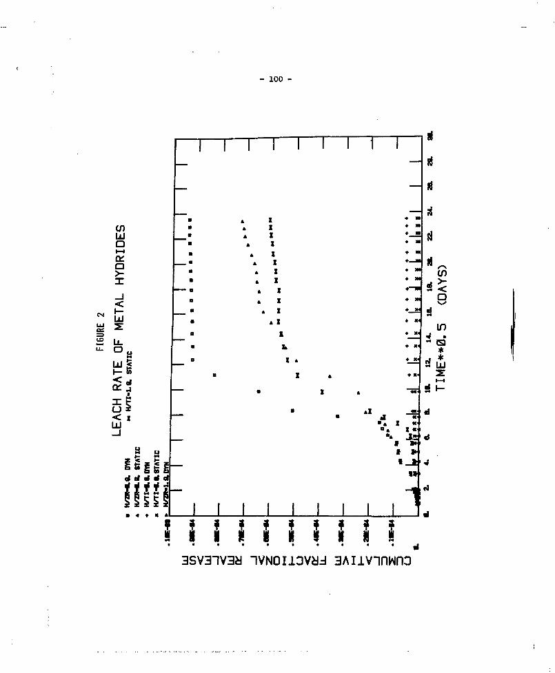
- 100 -
enLUa
iLLJ
a *if1
of «r d <t
I I I I I I
4 X4 X4 I4 X
4 X
4 X
1
Xt
X 4
X
•
•-
• x<
• K«
• X'
• X'
• X'
• x<
in
*LU
X «X«
f »f X*
I I
I I I I 1 1
I I I I I3Aiivnnwno

- 101 -
LEACH BEHAVIOR AND MECHANICAL INTEGRITY STUDIES OFIRRADIATED EPICOR-II WASTE PRODUCTS*
R.E. Barletta, K.J. Swyler, S.F. Chan and R.E. DavisNuclear Waste Management DivisionBrookhaven National Laboratory
Upton, New York 11973
During the accident at Three Mile Island Unit 2, several hundred thou-sand gallons of contaminated water were released to the auxiliary and fuelhandling building(l). This water was decontaminated using a demineralizationsystem, EPICOR-II. Most of the activity was localized on the first-stageliner (prefilter) of this system. Each 12 m diameter x 12 m high cylindricalprefilter contains typically 4.4 x 10*3 to 4.8 x 10*3 Bq of activity, not in-cluding daughters. The activity is mainly 137cs and 90gr. Gamma scans ofthese liners have indicated that the activity is not distributed uniformlythrough the prefilter. Rather, the majority of the activity in the liner islocalized in a narrow band within the cylindrical liner. The exact width ofthis band is not known at present. Using an assumed thickness of this layer,Swyler et al.(2) have estimated that the total absorbed dose to portions ofthe prefilter media could reach 10*> Gy in as little as two years. A dose of10? Gy in this concentrated layer could be achieved in approximately 30 years.
One management option which was considered for the prefilter /asteswas cement solidification. A resin solidification test program was undertakenby Hittman Nuclear and Development Corporation under contract to MetropolitanEdison Company^) in order to define the optimum formulation, or range offormulations necessary to solidify the prefilter material with cement. Thistest program, however, did not address the effect of radiation upon the me-chanical properties of the solidified composites, or their leachability. Thisstudy addresses these two areas. Demineralizer material for both programs wassupplied by the vendor of the EPICOR-II system.
A series of experiments were performed to measure the effect of irradia-tion on the leachability and mechanical integrity of solidified, simulatedEPICOR-II waste. These properties were measured for composites which werefabricated from irradiated ion exchange media, as well as for those irradiatedafter fabrication. The ion exchange medium used (D-mix) was claimed by EPICORto be representative of the prefilter material. The resin/cement formulationused was recommended by the Hittman/Met-Ed study. Two doses, 10& Gy and 10?Gy, were selected to bound short- and long-term storage. The leachability ofthe composites was measured at room temperature using a modified IAEA leachtest(4). xhe mechanical integrity of the composites was measured usingMCC-ll(5).
The results of the leach study are summarized in Table 1. The datais presented as the average cumulative fraction released normalized by the
*Work carried out under the auspices of the United States Nuclear RegulatoryCommission.

- 102 -
volume-to-surface area ratio (V/S). Unirradiated D-mix/cement composites in-dicate Cs and Sr release is as much as a factor 30 times lower than that re-ported in the literature for resin/cement composites. This could be due tothe presence of zeolites and/or sodium metasilicate in the composite. Com-posites fabricated from D-mix which had been irradiated prior to fabricationshowed only slight increases in the Cs and Sr releases. Composites irradiatedafter fabrication showed a slight decrease in the Cs release upon irradiationand a slight increase in Sr release.
TABLE 1: Results of Leach and Mechanical Integrity Tests onD-Mix/Cement Composites
Ave. CumulativeFraction Releaseda
x V/S x 102 (cm) _Dose -, - T
Sample Preparation (Gy) Cs Sr (MPa)
Unirradiated 0 2.2 ± 0.2 0.79 ± 0.07 1.2 ± 0.3D-mix irradiated prior 106 2.1 ± 0.5 0.65 ± 0.05 1.2 ± 0.2
to fabricationD-mix irradiated prior 107 3.4 ± 0.5 1.9 ± 0.3 1.0 ± 0.3
to fabricationSolid irradiated after 106 0.95 ± 0.11 0.98 ± 0.41 1.4 + 0.3fabrication
Solid irradiated after 107 1.18 ± 0.03 1.11 ± 0.3 1.4 + 0.3fabrication
^eionized water leachate, 30 day leach test at room temperature.
The_mechanical integrity as measured by the average fracture tentilestrength (f) of these composites are also listed in Table 1. Within the varia-tion of the measurement, no deleterious effects were observed in the mechanicalintegrity of D-mix/cement composites as a result of irradiation.
REFERENCES
1. U.S. Nuclear Regulatory Commission, "Final Programmatic Environmental Im-pact Statement Related to the Decontamination and Disposal of RadioactiveWastes Resulting From March 28, 1979 Accident Three Mile Island NuclearStation, Unit 2", NUREG-0683, 1981.
2. K.J. Swyler, R.E. Barletta, R.E. Davis, "Review of Recent Studies on theRadiation Induced Behavior of Ion Exchange Media", BNL-NUREG-28682, 1980.

- 103 -
3. Hittman Nuclear and Development Corporation, "Resin Solidification TestProgram", E-114-D-001, August 1980.
A. R.E. Barletta, K.J. Swyler, S.F. Chan, R.E. Davis, "Solidification ofIrradiated EPICOR-II Waste Products", BNL-NUREG-29913R, 1981.
5. Materials Research Center, "Tensile-Streagth Test MCC-11", December 1980,Draft Report.

- 104 -
RADIOLYTIC EFFECTS ON ION EXCHANGERS DOSINGTHE STORAGE OF RADIOACTIVE WASTES
K.K.S. Pillay* and G.E. Palau***Los Alamos National Laboratory, Los Alamos, NM, USA
**The Pennsylvania State University, University Park, PA, USA
Synthetic ion-exchange materials are extensively used inradioactive waste processing and in the stabilization and isolation ofradionuclides. In many of these applications, the total radiationexposure to the ion-exchange matrix is low, and therefore, the radiolyticeffects are minimal. However, there are a number of importantapplications in reactor coolant maintenance and decontamination ofnuclear facilities during recovery operations and decommissioning wherethe specific activities of the radionuclides are such that they can causea variety of operational problems as a consequence of radiolyticdecomposition.
Ionizing radiation doses of 10 kGy (1 HRad) or more are known tochange both the mechanical and chemical properties of organicion-exchange materials. Inorganic ion exchangers, because of theirwell-defined chemical characteristics, are generally believed to be moreradiation resistant. The degree to which radiolytic effects influencethe use of ion exchangers in waste management was examined through acomprehensive literature survey and a series of confirmatoryexperiments (1). The ion exchangers chosen for experimentalinvestigations were identical to the materials used in the cleanupoperations at the Three Nile Island, Unit-2 (TM1-2) reactor facility.
The objective of this investigation was to determine theconsequences of radiolytic effects on ion-exchange matrices during thestorage and disposal phases of waste management. Samples of syntheticorganic and inorganic ion exchangers were exposed to accumulated doses ofup to 5 x 10' Gy under a variety of conditions experienced during wastemanagement operations. The experimental studies (1,2) were designed toexamine the potential of (i) desorption of radionuclides from theion-exchange matrix during storage; (ii) gas generation and itsconsequences; (iii) agglomeration; (iv) pH changes; and (v) corrosion ofmild steel and/or stainless steel in contact with the ion exchangers.
The literature survey (1,3) confirmed that there is considerablegap in our knowledge of the radiolytic effects on ion-exchange materialsused in waste management. This is attested to by the increasing numberof reported incidents resulting from radiation damage to ion exchangersused in the nuclear process industry (3). The experimental studiesfurther confirm some of the predicted problems to waste managementoperations using synthetic ion-exchange materials.

- 1C 5 -
The findings of experiments conducted to determine the corrosionenhancement in steel containers are summarized here as an example of theresults of this study. Metal coupons embedded in ion exchangers andexposed to radiations from a 6 0Co source to a total accumulated dose of1.1 x 10' 6y showed the following:
(1) The stainless steel coupons exposed to radiation displayed amicroscopic pitting not detectable on the unirradiatedsamples. The irradiated mild steel coupons exhibit a weightloss 2 to 15 times greater than their unirradiatedcounterparts.
(2) Weight losses for mild steel coupons ranged from 0.1 percent
to 4.5 percent; whereas all stainless steel coupons exhibited
less than 0.01 percent total weight loss.
(3) Although both stainless steels used in the experimentsexhibited significantly greater corrosion resistance than themild steel, the 304 SS consistently displayed less corrosionresistance than the 316 SS.
(4) The moisture content of the matrix had a significant effect oncorrosion. The mild steel exhibited the greatest effect, withweight losses being 2 to 10 times greater for the drip-drysamples than the air-dry samples.
(5) The presence of an organic ion exchanger in the matrixincreased the metal corrosion process. The 304 SS exhibitedthe most dramatic change.
It is the conclusion of this investigation that ion-exchangematrices loaded with high-specific-activity radionuclides undergoradiolytic changes. These changes manifest themselves in (i) degradationof the ion-exchange matrix; (ii) desorption of radionuclides from thesolid phase; (iii) extreme changes in pH within the medium; (iv) partialdissolution of solid phase; (v) partitioning of the liquid phase;(vi) agglomeration of organic resins and admixtures of organics andzeolites; (vii) corrosion of container materials; and (viii) gasgeneration leading to pressure buildup with potential explosion and firehazards. While continued investigations to understand the mechanism ofradiolytic decomposition of ion exchangers are essential, in the nearterm a concerted effort must be directed at limiting waste loading andthe indiscriminate mixing of ion exchangers used in radioactive wastemanagement.
ACKNOWLEDGEMENT
This investigation was conducted at the Pennsylvania StateUniversity and was supported in part by the US Nuclear RegulatoryCommission through Brookhaven National Laboratory and the US Departmentof Energy through Argonne National Laboratory.

- 106 -
REFERENCES
1. K.K.S. PiHay, "Radiation Effects on Ion Exchangers used inRadioactive Haste Management," The Pennsylvania State UniversityReport NE/RWM-80-3 (1980).
2. G.E. Palau, "Investigation of the Consequences of Radiation Effectson inorganic Ion Exchangers", M.S. Thesis, The Pennsylvania StateUniversity (1982).
3. T.E. Gangwer, M. Goldstein, and K.K.S. Pillay, "Radiation Effectson Ion Exchange Materials", Brookhaven National Laboratory Report,BNL-50781 (1977).

- 107 -
RADIOACTIVE LIQUID FILTER WASTES HANDLING AT DARLINGTON G.S.
A.D. Mackie and K.K. Lo
Ontario HydroToronto, Ontario
Radioactive liquid filters are essential to the successful operation ofnuclear generating stations. When these filters are spent, they must bereplaced. Through operational experiences, it was recognized that the handlingof the spent filters and their subsequent storage/disposal should be consideredduring the design stage of the filters themselves. Handling, transportationand storage procedures for radioactive spent liquid filters have been improvedwith each successive nuclear generating station that Ontario Hydro constructs.Present in-station hand! .g techniques feature disposable filter containers orremovable filter internals which require special cans for transport andsubsequent storage at Ontario Hydro's Waste Storage Site. This paper describesprocedures for handling spent filter wastes and the development of specialequipment and facilities to optimally handle them at the Darlington NuclearGenerating Station.
The philosophy of handling filter wastes has been changed in that thewastes are no longer considered solely a byproduct of another system. Thefilter and the process of restoring its function are considered a systemitself. This system approach integrates waste handling procedures with thedesign of the filter. Three standardized system purification filters are beingdesigned for Darlington GS. Reusable filter vessels and removable filtercartridges permit one filter cartridge replacement procedure to apply for allstation filters. Each filter vessel houses one removable filter cartridgewhich is either a single 73 mm diameter tubular shaped element, a basket ofthree single elements, or a basket of thirteen single elements. Anticipatedcontact dose rates from the spent cartridges range from 1 to 100 rem/h.
Subsequent to being removed from a system, the integrally shieldedfilter vessel is transported to a centrally located and dedicated FilterHandling Room, where the spent radioactive filter cartridge is remotely removedand placed in a storge/transportation can; the filter vessel flushed andcleaned; and a clean filter cartridge installed in the vessel. The remoteoperation of removing the spent filter cartridge and transferring it into thestorage/transportation can is controlled from an operators console in ashielded operators's room. A glass viewing window and TV monitor facilitatethe remote operation. To verify this handling concept a project was initiatedto develop a remotely controlled gripping mechanism and related auxiliarytools.
An automatic gripping device, which operates in conjuntion with anoverhead crane system, was developed to perform the required remote operations(see Figure 1). The automatic gripper is a compact, air operated device, 60 mmin diameter and 430 mu in length, which grips onto the components that requireremote handling: the filter cartridges, the transportation/storage can lid,shielding covers for the filter vessels and transportation flasks, andauxiliary tools.

- 108 -
A compartmentalized storage/transportation can ('drip can') wasdeveloped in conjunction with this automatic gripper. One drip can will storeeither fourteen single filter element cartridges, three 3-element basketcartridges, or one 13-element basket cartridge. Once full, a drip can lid isremotely latched and bolted onto the drip can body, effectively sealing itscontents for a design life of 50 years. A prototype automatic gripper and dripcan have been successfully constructed and tested.
The gripping device will also be used at Ontario Hydro' s Waste StorageSite for the semi-automatic placement of loaded drip cans in engineered storagefacilities.
The new filter design and handling techniques represent a processoptimization which has evolved from past Ontario Hydro experiences. Reusablefilter vessels reduce replacement costs and the smaller quantities of wasteminimize transportation and storage costs. The Filter Handling Room and thefilter cartridge replacement operation provide an efficient and automated wastehandling technique which minimizes occupational dose expenditures. The sealeddrip can provides for retrievable storage and permits flexibility in futurewaste handling and storage.
FIGURE 1: PROTOTYPE AUTOMATIC GRIPPER AND DRIP CAN
The automatic gripperlatches onto aspecifically designedlifting pin which isattached to allcomponents that requireremote handling.Illustrated is asimulated single filterelement cartridge beinglowered by the gripperinto a drip cancompartment. A drip canlid (with centrallylocated lifting pin) isadjacent to the dripcan.
- 109 -
SOCIAL ASPECTS OF SITING GEOLOGICRESEARCH AREAS FOR NUCLEAR FUEL WASTE MANAGEMENT
THE CANADIAN EXPERIENCE
EcR. FreehAtomic Energy of Canada Limited
Whiteshell Nuclear Research EstablishmentPinawa, Manitoba
The "not in my backyard" syndrome is now generally accepted as a real andsubstantial impediment to waste disposal siting. Recently, a number ofcountries, including Canada, have found difficulty not only in finding sites forlow-level nuclear waste disposal facilities, but even in finding publiclyacceptable places to conduct geological research necessary to assess the safetyof the geologic disposal concept for nuclear fuel waste disposal.
This phenonemon first manifested itself in Canada in 1977, a few yearsafter Atomic Energy of Canada Limited (AECL) started its geological researchprogram in Ontario. In March of that year, more than 1000 people at a publicmeeting in the town of Madoc in southeastern Ontario told AECL in no uncertainterms that they did not approve of such research in their backyard.
The geological research conducted in the Madoc area, which waspreliminary to deep drilling, had been based on informal agreements among AECL,Ontario Hydro, the Canadian government and the government of Ontario. The 'public opposition to the research resulted in some political uncertainty, andAECL was instructed to discontinue its activities in Hastings County, whichincludes Madoc. AECL continued geologic research at its own sites, the ChalkRiver Nuclear Laboratories in Ontario and the Whiteshell Nuclear ResearchEstablishment in Manitoba.
The aarly difficulty at Madoc wa- followed by the signing of theCanada/Ontario Nuclear Fuel Waste Management Program agreement in 1978 Junewhich established the following points:
-The two governments jointly agreed to pursue research which wouldculminate in the demonstration of deep underground disposal of nuclearfuel wastes in the Ontario portion of the Canadian Shield.-AECL would be responsible for research on the immobilization anddisposal of the wastes.-Ontario Hydro would be responsible for research on interim storage andtransportation of used fuel.-The prior approval of the Government of Ontario would be required at Leach step of the geological research program. L
dIn application, the process of obtaining Ontario*s approval required AECL s
to obtain permission of the nearest local council for any research, even for gsuch a simple activity as obtaining rock and water samples. t

- 110 -
The approvals processes, and the AECL information and community relationsprograms that accompanied them, produced some successes. These early successesprompted some observers to tout the Canadian approach as a potential solution tothe "not in my back yard" syndrome. There were, however, some considerableunforeseen difficulties that have since caused a change in the Canadianapproach.
The first and most persistent of these difficulties was the one ofseparating, in the minds of the public, the generic research program to assessthe disposal concept from the future selection of a disposal site. Someresidents of areas where research was proposed reasoned that to preserve theirright to object to a disposal vault nearby, they had better object to theresearch, as it might ultimately lead to a disposal vault. This was oftenexpressed as a fear that AECL was "getting its foot in the door".
A second difficulty was a pre-existing alienation of northern Ontariofrom.the southern, industrialized part of the province. There was apredisposition on the part of residents of northern Ontario to refuse to haveanything to da with the disposal of wastes which were perceived to have beengenerated by processes that provided employment and comforts in the south.
A third difficulty was that a small and scattered, but neverthelessvocal, well-organized and dedicated movement opposed to nuclear energy activelyopposed the research program at every turn, often convincing municipalcouncillors through intense lobbying that they should not pass the requiredresolutions that would allow field research to proceed.
The councillors, for their part, had few reasons to support the researchin their vicinity, even if they were convinced it should be done somewhere,since the research program offered few jobs or other economic benefits.
On 1981 August 4, the governments of Canada and Ontario jointly announcedthe following:
-Geologic research would be carried out at two additional rockformations in unorganized territories, which were named.-The generic research phase of the program was being separated from thesite selection phase by independent regulatory and environmental reviewand public hearings.-General field studies would henceforth be approved routinely by theCanada/Ontario Co-ordinating Committee without reference to municipalauthorities.-AECL would continue to keep residents of areas where research was beingundertaken fully informed about what was happening.
The two new research areas, together with the two earlier ones at WhiteLake and Atikokan, in Ontario, two ABCL-owaed sites and the Underground ResearchLaboratory in Manitoba, are expected to provide most of the necessary technicaldata for the evaluation of the disposal concept. Public acceptance for thesiting of the Underground Research Laboratory was obtained by the use of agovernment guarantee that no nuclear waste would be used in the research, andthat the laboratory would not subsequently be converted to a disposal vault.
There has been considerable negative reaction from the residents of one

- Ill -of the communities near one of the research areas announced on 1981 August 4.Because the research area is outside municipal jurisdiction, and the provincialgovernment, which owns the land, has given its permission, the program iscontinuing.
Despite this and other sometimes strong opposition, the Canadian Nuclear FuelWaste Management Program has been able to develop sufficient support to allowits geologic field research to continue. However, this success should not beinterpreted as a solution to the "not in my back yard" syndrome, which is stillprevalent and which will need to be faced during the future process of selectinga site for a disposal vault.

- 112 -
DEVELOPING SOCIAL IMPACT ASSESSMENT METHODOLOGIESFOR LONG-TERM DISPOSAL OF IRRADIATED FUEL
B.G. Rogers and M.A. StevensonOntario Hydro
Toronto, Ontario
Ontario Hydro is contributing to the Draft Generic Pre-ClosureEnvironmental and Safety Assessment for the Nuclear Fuel Waste ManagementCentre, Concept Assessment Phase. Social and community impact assessments(SIA's) are prepared as part of the environmental assessment process.
The SIA's examine changes to communities generally resulting from newdevelopments. The social and community impact assessments are generallybroad in scope. The range of concerns addressed are based on theEnvironmental Assessment Act of Ontario, which defines "environment" asincluding "the social, economic and cultural conditions that influence thelife of man or a community".
The purpose of this paper is to outline the methodologies used inpreparing two SIA's for the environmental assessment process: thereference community SIA, a preliminary SIA for assessing the impact of awaste repository on potential sites; and the fuel transportation SIA, anSIA for assessing the impact associated with the transportation ofirradiated fuel, to the repository site.
REFERE?3CE COMMUNITY SIA
The SIA methodology is applied to four reference communities (a town,township, county, and new town). Detailed community profiles areprepared. A set of 13 social factors have been developed that describe thesocial and economic components of a community. These factors serve asguidelines for the analysis. Some of the factors are easily quantifiable(e.g. employment structure and incomes) while others are not (e.g. socialaspects).
In order to assist in the assessment of the work force-relatedeffects of the project characteristics on the communities, a simplecomputer model has been developed. By applying selective multipliers towork force estimates, it generates total influx of workers, families andservice sector personnel for both construction and operations phases.
The effects of the development of the project on the community areidentified and their significance determined. A preliminary set ofcriteria are used to assess the significance of the effects of each socialfactor. Those significant effects are considered to be impacts. Once theimpacts have been identified, mitigation measures are proposed.

- 113 -
In this study, an attempt was made to identify any social factorswhich define important aspects of the communities. If it were known inadvance which factors are most important, then a greater effort can be madeat the site selection stage to pre-select from a wide range of communitiessome reasonably appropriate sites.
Preliminary measures of community adaptability and acceptance weredeveloped for each of the 13 social factors. The measures provide aninitial understanding of why a community would be receptive or unreceptiveto a Nuclear Fuel waste Management Centre. The study concludes byidentifying research and methodological directions for the site selectionstage.
IRRADIATED FUEL TRANSPORTATION SIA
The primary purpose of the Irradiated Fuel Transportation Study is todevelop methods and to identify data requirements for the assessment of thepotential socio-economic impacts of transporting irradiated fuel to aNuclear Fuel waste Management Centre. A subsidiary purpose is to formulatea procedure for evaluating the relative environmental effects of thedifferent modes and routes which may be proposed for the program. Due toits unique aspects, the study is preliminary in nature.
Qualitative impact matrix analysis is proposed for the methodologicalframework. The psychological, social, economic and institutional effectsof the three possible modes on the three different human environments areselected for study. The three modes are road, rail and barge and the threeenvironments are urban, rural and recreational settlement areas.
Svidence suggests that the principle factor influencing thegeneration of most effects will be risk perception. This finding has anumber of implications for: 1) concept formulation, 2) data collection, and3) research instrument selection.
The anticipated roles of risk perception requires explicit treatmentof direct psychological effects as well as indirect psychological effectswhich assume social, economic and institutional forms. This considerationcontributes to the choice of the four categories of effects employed in theanalysis. The study of risk perception also implies the need to collectthe "subjective" data. Public attitudes and beliefs are of criticalimportance. The choice of research instruments is affected as well. Moreemphasis is placed on the need for interviews, focus groups and socialsurveys than is usual in impact analysis.
As a first effort in defining the possible range of subjectiveeffects, focus groups were conducted. These provide insight into thenature of public concerns and suggest areas for future research. Althoughthe study adds to our knowledge of the kinds of effects which thetransportation program may generate and suggests methods for forecastingthem, it also demonstrates that more work is needed in determining theincidence, strengths and significance of these effects. Information onthese matters will be vital in developing a mitigation program.

- 114 -
To summarize, the following significant new results are presented: amethodology for assessing the social impacts of a waste repository; thedevelopment of criteria for identifying impacts; the development ofmeasures for identifying community adaptability and acceptance, amethodology for assessing the social impact of transportation of irradiatedfuel and the importance of risk perception.

- 115 -
THE ROLE OF THE MEDIA IN STRUCTURING PUBLIC CONCERNS ABOUTNUCLEAR FUEL WASTE MANAGEMENT
G.M. GilmourSocial Science Research Consultant
Scarborough, Ontario
and
Bryn Greer-WbottenYork university
Downsview, Ontario
Relationships between public attitudes to nuclear power and mediareports on nuclear-related events are complex and difficult to determinein any direct manner. The difficulties are found on both sides of thepresumed relationships: in the analysis and interpretation of publicattitudes, and in the treatment of media reporting. In this paper, wepresent some findings from an analysis of newspaper reports concerningthe management of nuclear wastes, and attempt to relate the findings tothe more problematic area of specifying linkages between media and publicattitudes.
The relevance of such social scientific research rests on theassumption that the public does have a meaningful role to play in thedecision-making process with respect to nuclear power, and especially thesiting of controversial facilities. If decisions are then viewed as aresolution of conflicting interests and information, media reportsminimally provide data which can be analysed in order to help understandthe process in a more meaningful way.
The empirical research reported here is drawn from a contentanalysis of some 3,000 nuclear-related articles, found in both daily andweekly newspapers in several regions in the Nuclear Fuel waste ManagementProgram (N.F.W.M.P.) over the period of March 1980 - February 1981. Thequantity of nuclear articles increased over the year, although theproportion (about one-third) that referred specifically to waste wasrelatively constant. Reporting became increasingly negative towards theend of the period, influenced by high levels of anti-nuclear oppositionto the siting of the Blind River refinery. Articles more specificallyconcerned with the N.F.W.M.P. were noticeably technical in orientationinitially, but were characterized by & set of socio-political issueslater. The concerns of the public, as reported by the press, were quitebroadly-based: health and safety, environment, transport of wastes,economic and employment effects, etc. Such concerns are well-known andmay be said to form an information base for public attitudes.

- 116 -
Somewhat less evident are concerns derived from the closemonitoring of nuclear reports over the year that refer to thedecision-making process itself. Although these concerns were present inthe Blind River situation (as would be expected in any controversialsiting), they were especially evident in public reactions to theN.F.W.M.P. A central issue is the legitimacy of the actors involved indecision-making: does a council have the 'right1 to speak for a 'local'population? Who has final veto in a siting decision? These and similarquestions relate to feelings of political powerlessness, to a lack offaith in government and its institutions, to a loss in the credibility ofsponsors. In this particular case, the context of North-South sentimentsis also important. The political escalation of the debate on nuclearwastes might be seen as an outcome of mounting public concerns, whichthemselves were increasingly better articulated by anti-nuclear groups.
Media reports on events were often quite balanced, giving as muchspace to both pro- and con-arguments. On the other hand, letters to theeditors - perhaps the cutting edge of public criticism of nuclear power -became increasingly negative, used more sophisticated arguments, andcalled upon non-local sources of expertise. In fact, the growth of localanti-nuclear opposition groups was aided by provincial or national levelorganizations, whose spokesman brought in new information, maintainingthe broad base of concern and building upon each new 'crisis' situationto add to the repertoire of critical arguments.
Details of these events are found in the local (weekly) newspapers,and several months may pass before a summary is reported in a daily.Weeklies are often said to 'reflect' local opinions, rather than formingthem. The provision of information related to the decision-makingprocess, however, likely serves to structure public concerns in acontroversial area, as does emphasis given to the arguments used by theactors involved. If 'local control' is the underlying political issue,then weeklies may take on a more active role. Certainly, the generaldecentralization arguments used by anti-nuclear groups would bolsterpublic opposition at a local level.
Another opposition argument - nuclear proliferation - also surfacedin reports on Blind River. The emotion/fear-based response seen in manyletters ('the ultimate public concern') is noteworthy in its implicationsfor the presumed relationships between media and the public. 'Publicattitudes to nuclear power' are often based on opinion polls, but thedata from such surveys only tap one element of attitudes - the cognitiveor belief component. Polls do not evaluate the affective orsentiment-based components of attitudes - such as the fears emanatingfrom concern over nuclear proliferation.

- 117 -
A recent development in communications theory, stressing theimportance of situational variables, may prove to be significant inattempting to sort out the influence of the media on public attitudes tonuclear power* Certainly, from the content analysis research reportedabove, the reactions of residents to controversial issues cannot bedivorced from an understanding of recent local events, relationships withother communities, etc. — all of which are reported in the media.
The implications of specific situations, however, do not maskoverriding fears/concerns about the entire nuclear fuel cycle; rather,they serve to emphasize them. The component parts of the cycle are notreadily distinguished by the public or, more likely, they are consciouslyrejected. Thus, Blind River and the N.F.W.M.P. are consistently linkedin public discussions: problems in one feed on problems in the other. . . to the bomb; sponsors are interchangeable and regulatory agenciesbecome sponsors. The correctness of such reports is not at issue.Rather, they reflect public concerns/attitudes that do not make the samedistinctions as the sponsors or regulators. The problem is defined in adifferent way.
ACKNOWLEDGMENT: The research reported here was partly supported by acontract to G.M. Gilmour by Ontario Hydro - Atomic Energy of Canada Ltd.

- 118 -
THE ONTARIO PUBLIC'S OPINION OF NUCLEAR FUELWASTE MANAGEMENT
M.A. Greber and M. BarradosAtomic Energy of Canada Limited
Ottawa, Ontario
Studies of the opinions of Ontario residents have shown that theyexpress a great deal of concern about the question of disposal of nuclearwaste material and that they perceive the demonstration of the safe dispos-al of nuclear waste to be an urgent matter. While there appears to beclear public consensus that the question of proper handling of high levelwaste is of great concern and that the question should be dealt with quick-ly, actual program implementation has not had the same unequivocal support.
Atomic Energy of Canada, as the lead agency for research into themanagement of nuclear fuel wastes, has the responsibility for carrying outthe information portion of the Nuclear Fuel Waste Management Program.Atomic Energy of Canada regularly participates in Gallup Ontario OmnibusSurveys to evaluate public awareness of the waste management program, toidentify further information requirements, and to measure public supportfor various phases of the program. We have participated in these surveyssince June 1978 and have been able to monitor changes in public opinion.In addition to the provincial surveys, specific community studies have beencarried out. Studies carried out in conjunction with various informationactivities have shown:
1. While genuinely concerned about the issue of disposing ofnuclear fuel wastes, many Ontario residents do not know aboutthe research program'which is in place to address the issue.
2. Support levels for various phases of the program are verydifferent.
3. Evaluation of one portion of the program is frequently confusedwith another.
4. Issues associated with siting of an eventual facility are oftenemotional and based on fear.
Program activities have been found to be associated with smallincreases in knowledge levels in the province and larger increases inspecific communities, particularly where active information and communityrelations programs have been undertaken. Low knowledge levels are found tobe particularly associated with information such as the types of wastesinvolved, the agencies involved in the program and knowledge about thedifferent phases of the program.

- 119 -
Levels of support for the two phases of the program, research Intodisposal and site selection, differ. Ontario residents are more supportiveof research drilling than of possible siting. Although in the past therehas been little significant change in attitudes towards research drilling,recent studies indicate a very gradual increase in the level of opposition.Qualified support, those not opposed but wanting more information, remainshigh.
Northern Ontario residents are somewhat more opposed than residentsof the province as a whole and this opposition appears to be increasingover time. The increase in opposition appears to result from the percep-tion that research activities lead inevitably to selection of the area as asite for a waste disposal facility.
Acceptance by the Ontario public of locating a waste disposal demon-stration facility near their community, given that the research program hasbeen successfully completed, remains low. Survey findings over time indi-cate that those who were initially indifferent towards siting have nowbecome negative. In addition a sizeable proportion of respondents wantmore information before giving an opinion. However, when this group isforced to make a choice, most consider a potential site unacceptable. Themain reasons given for being opposed to siting a demonstration facilitynear the community are concerns with health and safety.
Most of the concerns and issues surrounding siting are emotional andbased on fear. Most people cannot think of any advantages of having awaste disposal facility located near their community. Ontario residentsare much more likely to give disadvantages such as dangers of radioac-tivity, dangers to health, environmental dangers and the chance of anaccident.
Analysis of structured group discussions held with select residentsof the province on the perception of risks, also suggests that the questionof fear is an important element in public attitudes towards nuclear powerand nuclear waste management. The findings indicate that there is a fearof the unknown. The focus of the public is not on whether there is achance of an accident occuring, but rather a concern of what will happen ifit does occur.
Our studies have shown that there is continuing need to provideinformation on the waste management program to Ontario residents so thatthey will become more familiar with the program and its objectives.Providing information would not necessarily result in increased acceptanceof any phase of the program, but would make a substantial contribution toreducing fears associated with the unknown and unfamiliar.

- 120 -
Some progress in increasing information levels in the province hasbeen made to date although there Is much more work required, particularlyin providing general information to all Ontario residents and more programspecific information to communities who are directly affected by any partof the program. Information which is most frequently requested is generalinformation on the program, and information on the dangers involved.
With the new program directives taken by the two governments,Ontario Hydro and AECL, not only will there be continuing requirements forinformation programs, but also a need to work closely with Ontariocommunities. The community emphasis is required to identify specificconcerns and interests as well as advantages to the community associatedwith the waste management program.

- 121 -
THE AECB APPROACH TO CONCEPT ASSESSMENTFOR HIGH-LEVEL RADIOACTIVE WASTE DISPOSAL
Paul J. Conlon and K.P. WagstaffAtomic Energy Control Board
Ottawa, Ontario
In August, 1981, the governments of Canada and Ontario unveiled theprocess by which regulatory and government evaluation of the deep geologicaldisposal concept for high-level radioactive waste would be. undertaken. Thisprocess is to be known as Concept Assessment and the announcement outlinedthe roles of the various agencies involved and identified the major steps inthe process for issuance and review of relevant documents and publication ofstatements on the disposal concept.
It is the responsibility of the Atomic Energy Control Board (AECB) toensure that the disposal concept is subjected to a thorough regulatory review.This is to be accomplished with the cooperation of the Ontario Ministry ofEnvironment and Environment Canada. Government evaluation of the concept willalso include a public hearing (or hearings) under federal auspices.
One of the first steps in the Concept Assessment process involved thepublication by the AECB of an initial statement on the regulatory review andassessment of the disposal concept. This appeared as AECB Consultative DocumentC-71, a proposed regulatory policy statement that describes the philosophicalperspective from which the various reports supporting the concept will bereviewed by the Board in cooperation with the environmental agencies.Consultative Document C-71 outlined the required scope of the generic assessmentexercise, the factors that should be examined in the Concept Assessment reports,the extent to which reviews, analyses and predictions should be taken and theradiological performance criteria upon which judgements of acceptability willbe based. The AECB and the environmental agencies must be convinced that theconcept can be undertaken safely before agreeing to consider further steps inthe licensing process.
It is important to ensure that the technical assessment of the conceptis both thorough and comprehensive. This requires that the problem be properlydefined and that all relevant aspects receive appropriate consideration. Itmust be evident from the documentation submitted in support of the concept thatthis has been properly done.
This overall technical assessment must demonstrate to the regulatoryauthorities that a repository facility will be able to meet certain, performancecriteria and objectives for disposal. In the pre-closure phase of a facility,doses to workers and the public as a result of the facility must be withincurrent regulatory limits and are expected to be as low as reasonably achievable.With respect to the post-closure phase of a repository, it must be shown thatradiation doses to members of the public, attributable to the existence of arepository, will be unlikely at any time to exceed a small fraction of the doseswhich would be received from natural background radiation, that the disposalsystem and its components are capable of accommodating disturbances due tonatural phenomena likely to occur in the vicinity of the repository and thatany increase in risk to the public as a result of these disturbances will notbe significant.

- 122 -
The proposed concept is expected to incorporate a defence-in-depthapproach based upon the use of multiple barriers. The repository will not beallowed to close until sufficient technical evidence has been assembled toconclude with a high degree of certainty that the facility can be abandonedwithout the need for post-closure monitoring. Therefore, the disposal conceptcannot include post-closure monitoring for technical reasons, although othersocietal concerns may make this necessary, nor can retrieval of the waste bea design factor in the post-closure phase.
The AECB recognizes the limitations placed on this technical assessmentby the generic nature of the exercise. The use of predictive models and alimited data base is unavoidable. However, these must be compensated for bytaking as broad a view of the problem as possible, one that includes aconsideration of contingencies and that describes the statistical confidencewith which the results may be viewed.
As a further contingency measure, the proponent must maintain a currentawareness of alternative disposal options and inform the AECB of steps whichare being taken in this regard.
Government evaluation of the concept will include a public hearing (orhearings). A thorough review of the socioeconomic implications of the conceptwill take place at that time with due recognition of the limitations imposedby the generic nature of the assessment.

- 123 -
A PRACTICAL APPLICATION OP CRITERIA FOR THE CLEAN-UPOF CONTAMINATED COMMUNITIES
Roger S. EatonTechnical Secretary-
Federal Provincial Task Force on RadioactivityAtomic Energy Control Board
Ottawa/ Ontario
In 1975 as the Atomic Energy control Board shifted its emphasis on tothe nuclear regulatory aspects of electric power generation, time was takento review past practices in the processing and use of radioactive materials*
As part of this survey one community, Port Hope, Ontario, a centrefor radium and more recently uranium refining was found to have beenextensively contaminated. With public knowledge of this, there was aperceived need for rapid action and the Federal Provincial Task Force onRadioactivity was established in February 1976.
The first phase of this program has now been completed. Using aprivate consulting firm as project manager, about 3,500 houses have beensurveyed and some 450 buildings and sites have been decontaminated. Thewaste generated included soil from housing lots and public works projectsand building materials. One household which had to be decontaminated wasof historical interest to the Canadian nuclear program. A flood alsoprovided some interesting effects.
Approximately 100,000 Mg of contaminated soil and about 2,000 Mg ofused building material, mainly wood, was trucked to a specially preparedsite at CRNL. Material was initially collected at a fenced location inPort Hope for onward trucking to Chalk River. A positive accounting systemwas used to prevent diversion and there were no accidents in the thousandsof truck movements involved. While the CRNL site was closed in late 1979,this fortunately coincided with the conclusion of most of the excavationwork associated with housing.
With the closure of the site, a temporary storage facility wasestablished in Port Hope near the sewage treatment plant. This site, asmall paved and fenced area/ has been used to receive the waste uncoveredby the flood and any incidental wastes from homeowners who have added totheir homes or from small public works projects. This site is now alsoclosed as its capacity of 3,500 Mg has been reached. While permission toexpand has been obtained, no money is available to do so because of theinjunction resulting from legal action taken over the proposed movement ofsimilar material from a site in Scarborough, Ontario.
Phase II, to complete the decontamination of the town, awaits theestablishment of a low-level waste management site. Some 200,000 Mg ofmaterial averaging less than 4 Bq/g (100 pCi/g) of radium will be removedfrom seven ravines and open areas in the town. In addition, considerationis also being given to dredging the yacht basin which is contaminated byboth radium and uranium.

- 124 -
One major aspect of the Task Force's operation has been theestablishment of criteria for site decontamination. These criteria wereestablished to permit remedial action both on an interim and long-termbasis. Three levels of action were chosen for radon and radon daughters:prompt interim action, primary criterion and an investigation level. Thefirst level required the application of a certain but inefficient systemwithin weeks of discovery to be followed by a cheaper and more acceptablefix when the source had been established. The primary criterion is theaverage level to which all houses are eventally reduced. The investigativelevel is chosen to ensure than an average level will be obtained from whichit can be determined whether the primary criterion is met.
Gamma radiation measurement criterion for inside and outsidebuildings were also set up in a similar way.
These criterion have proven to be effective and have stood up for thefive years of the project.
While alpha contamination has not been a major feature of thisprogram, some practical values were established and their application isalso described.

- 125 -
LOW- AND INTERMEDIATE-LEVEL RADIOACTIVE WASTEMANAGEMENT IN CANADA
D.H. Charlesworth* and T.J. Carter+*Atomic Energy of Canada Limited
Chalk River, Ontario"•"Ontario Hydro,Toronto, Ontario
The important sources of low- and intermediate-level radioactivewastes in Canada are nuclear power reactors (10 operating, 14 under construc-tion), two federal nuclear research establishments, several radioisotopeand nuclear fuel production facilities, and a large number of medical, re-search, and industrial organizations which use separated radioisotopes andsmall research reactors. Large volumes of uranium mill tailings are also pro-duced but are not discussed in this paper.
Management of radioactive wastes began in Canada at the Chalk RiverNuclear Laboratories (CRNL) of Atomic Energy of Canada Limited (AECL), andsince the Laboratories were the major source of wastes in Canada for manyyears, the management methods adopted there have often set the pattern forwaste management in Canada. At CRNL all but the lowest category of wastesare emplaced in engineered near-surface containment structures and continuedsurveillance, maintenance and land-use control will be required throughoutthe storage period until the wastes are placed in permanent disposal facili-ties.
The three electrical utilities using CANDU power reactors (OntarioHydro, Hydro Quebec and New Brunswick Power) each have their own operationsfacilities for processing waste and up to 50-year storage of their reactoroperating and maintenance wastes. Ontario Hydro's Bruce NPD RadioactiveWaste Operations Site is by far the largest, receiving about 3800 n>3 ofwastes in 1980, but all three sites employ similar storage concepts modifiedto suit local hydrogeological and geotechnical conditions.
Processing of wastes via incineration and baling is practiced byOntario Hydro, and CRNL are nearing completion of a Waste Treatment Centrefor the incineration and conditioning of their low-level wastes prior tostorage. The immediate objectives of processing are volume reduction andstabilization to improve the storage operations. The conditioning of wastescan include the immobilization of solids as well as liquids and slurries inbitumen, water-extendable resins or other media. Consideration of waste con-ditioning and packaging based on storage requirements must also include theeventual requirements imposed by the final disposal system.
It is recognized that some component of the wastes presently in storagewill remain hazardous beyond the useful lifetime of the storage facilitiesand will require retrieval and restorage; or final disposal. Operating,maintenance and decommissioning wastes range from very slightly, if at all,

- 126 -
radioactive (90% of the volume) to very radioactive, requiring remote, shieldedhandling. All of these wastes have two features in common:
i) they are truly wastes with no present or future resource value,
ii) their storage requires present and ongoing commitments of resources thatcould be avoided by the early development of a disposal system.
In July 1980, Atomic Energy of Canada Limited/CBNL and Ontario Hydroestablished a common program on long-term reactor waste isolation. This pro-gram which does not include irradiated fuel nor fuel wastes, is directed atmatching wastes isolation and disposal concepts to various segments of thewide spectrum of reactor operating and decommissioning wastes on the basis ofhazard. For the most innocuous category of wastes, sanitary landfill facili-ties may provide the required degree of isolation. For the next level ofwastes, engineered near-surface facility concepts in clay and till, andintermediate-depth (a few hundred metres or less) concepts in bedrock, suchas shale and limestone, are being evaluated. For the most radioactive reac-tor operating or decommissioning wastes, deep geologic facilities being de-veloped in the Canadian Nuclear Fuel Waste Management Program may be required.Characterization and segregation of waste components is a prerequisite forthe successful application of these disposal concepts.

- 127 -
THE LOW LEVEL WASTE MANAGEMENT PROGRAMIN THE UNITED STATES
George B. LevinE G & G Idaho Inc.
Idaho Falls, Idaho, U.S.A.
The Low-Level Waste Management Program was established in September1978 by the U.S. Department of Energy. The goal of the program is todispose of low-level wastes in a manner that will protect public health andsafety over the long term. To accomplish this goal, the primary objectiveof the program is to provide an acceptable low-level waste managementsystem by 1988.
This objective has been and will continue to be achieved by workingcooperatively with states, other government agencies, industry and otherorganizations, and the public. Involvement of these parties will beencouraged not only in assessing the problems that the program mustaddress, but also in the development and implementation of possiblesolutions. The program has and continues to involve representatives frombroad interest areas in assessing policy, in developing recommendations,and in helping to formulate direction and emphasis for program activities.
A two-year effort in developing policy direction was completed inDecember 1981. The final national strategy for low-level waste managementoutlines 17 policy recommendations that, once adopted, should lead toestablishing an acceptable waste management system. Three major areas ofcommercial activity are already contributing toward achieving this programobjective.
TECHNOLOGY DEVELOPMENT
The technology development programs listed below are all scheduledfor completion by 1986. Two additional years will be allowed forintegrating the proven technologies into the commercial waste managementsystem. The Technical Implementation Plan, a document scheduled forcompletion this year, will consist of these eight components:
. Technology for waste generation reduction*
• Technology for waste treatment, handling, and packaging forshallow land burial.
. Technology and documentation required to open a shallow landburial site.
. Remedial action technology for shallow land burial sites.
. Technology and documentation needed to open a site providinggreater confinement than shallow land burial.

- 128 -
. Technology for waste treatment, handling, and packaging forgreater confinement than shallow land burial.
. A conceptual design for an engineered interim storage facility.
Integration of approved waste classification systems intotechnology development programs.
INFORMATION SYSTEMS
A computerized data base for low-level waste management has beenestablished based on a systems approach. Studies are continuing in orderto supply up-to-date waste generation and management information to thesystem. Development of a user's manual and the broadening data base willallow others easy access to the most current information available. Soonanybody may have access to this information.
INSTITUTIONAL HATTERS
Efforts have been successful in involving the public, organizedgroups, state and local governments, and industry in developing nationalpolicy. Since the Low-Level Haste Management Program serves a nationalaudience, it is imperative that a meaningful dialogue be maintained withthese groups. Activities in information exchange, document preparation andreview, and educational programming are continuing as planned.
States in several regions of the country are now in various stages offorming interstate compact agreements in response to the Low-LevelRadioactive Waste Policy Act of 1980. The transfer of technology and datato states and assistance to statewide planning are also progressing,fulfilling a Department of Energy commitment to support the compactingefforts of states.
The other federal agencies that are associated with low-level wastemanagement must be kept informed of these program activities and progress.Ongoing efforts in public participation, research, and rulemaking must becoordinated among federal agencies to avoid duplication and make the mosteffective use of limited staff and financial resources.
THE FUTURE
January 1, 1986 is a critical date in the management of low-levelradioactive waste in the United States. At that time, regions will be ableto exclude out-of-region waste. The Department of Energy Program willcontinue to support states in their efforts to obtain new disposal sitesand will continue to support the efforts aimed at obtaining betterinformation and better technology for low-level waste management.

- 129 -
THE JAPANESE APPROACH FOR THE MANAGEMENT OF RADIOACTIVE WASTES
Takehiko IshlharaRadioactive Waste Management Centre
Tokyo, Japan
FINAL SUMMARY PAPER NOT AVAILABLE AT TIME OFPRINTING

- 130 -
UNITED STATES DEPARTMENT OF ENERGYSURPLUS FACILITIES MANAGEMENT PROGRAM
Joseph F. Nemec*and Jerry D. White+*UNC Nuclear Industries; Richland, Washington USA
+U.S. Department of Energy? Richland/ Washington USA
Many government-owned nuclear facilities that were used throughoutthe early development of nuclear energy have no current use and have beenretired. However, these facilities have residual radioactive contaminationlevels requiring controls* Under the authority of the Atomic Energy Act,as amended, the United States Department of Energy established the SurplusFacilities Management Program to assure the safe caretaking and disposal (alsocalled decommissioning) of such facilities. About 500 facilities requiringremedial action have been identified and catalogued - approximately 75percent of which are located on the Hanford Site in eastern WashingtonState* The United States Department of Energy Richland Operations Officeis responsible for administering this program.
The program objectives are to:
o Eliminate potential hazards to the public and to the environmentfrom surplus facilities.
D Reduce the costs for ensuring that the facilities remain in asafe condition while awaiting decommissioning,
o Make surplus real property available for other uses wherepractical.
The inventory of facilities includes reactors, fuel processingplants, laboratory facilities, tanks, pipelines, waste treatment systems,solid and liquid waste burial grounds, and storage areas with uranium andthorium residues. The goal is to complete disposition actions on mostfacilities in the currrent inventory within the next 20 years.
Among the range of alternative actions that may be performed duringthe disposition of these facilities, the following three options arerepresentative of the varying degrees of time and funding required to placethe facilities in a safe condition.
In Option 1/ all nuclear process material is removed from the site,and the contaminated areas are sealed off. A program of maintenance andsurveillance is then performed on a continuous basis. Most facilities inthe Surplus Facilities Management Program are in this category, which isconsidered an interim measure prior to final disposition.
Option 2 is a more permanent form of protective storage that requiresless maintenance and surveillance effort than Option 1* In Option 2, majorstructural decontamination of the facility is performed and any remainingradioactive components are placed in a permanently sealed containmentvessel or structure. All non-essential structures are dismantled orreleased for other use.

- 131 -
In Option 3, the surplus facility is completely decontaminated, theneither dismantled or renovated for other use. In either case, the facilityis removed from the Surplus Facilities Management Program inventory uponcompletion of Option 3 actions*
Existing United States Department of Energy disposal sites will beused for disposing of the majority of the wastes and residue from thesedecommissioning projects. The Department of Transportation and state andlocal authorities will assist in determining the times of day and routesfor transporting any contaminated wastes to disposal sites.
There are four basic steps to this remedial action program. First,surveillance and maintenance ensure adequate containment of contaminationwithin the designated facilities and provides physical safety and securitycontrols. The second step, planning, identifies what needs to be done atthe facilities, estimates the costs, and then sets the priorities andschedules for the actions. The next step, disposition, is the actualcleanup of the facilities and the disposal of wastes. The final step,development and transfer of technology to the commercial sector, includesdevelopment of processes or equipment for decommissionina facilities, andproviding this knowledge to private industry as an aid to the eventualdecommissioning of commercial nuclear facilities. A plan for theseactivities has been developed and is kept current as new facilities forinclusion in the program are identified.
During 1981 and 1982, major decommissioning activities will be inprocess at the following sites (* indicates projects scheduled forcompletion by 1982)
o Niagara Falls Storage Site, New York, New Yorko Plutonium Laboratories, Mound Facility, Miamisburg, Ohio.o Monticello Remedial Action Project, Monticello, Utah* Advanced Fuel Laboratory, Vallecitos, California* Sodium Reactor Experiment, Santa Susana, California.* Plutonium Laboratories, Argonne National Laboratories, Argonne,
Illinois.
One of the largest of the current disposition efforts will be thedecommissioning of the Shippingport Atomic Power Station in Pennsylvania.This power plant is scheduled to be shut down in 1982. Decommissioningplanning and engineering is currently underway.
This paper presents the current status and plans of the SurplusFacilities Management Program and discusses near-term activities.

- 132 -
THE PRESENT STATUS AND FUTURE FLANS FORTHE REGULATION OF RADIOACTIVE HASTES IN CANADA
W.D. SMYTHEDirector General
Fuel Cycle and Materials DirectorateAtomic Energy Control Board
Ottawa, Ontario
The regulation of radioactive wastes in Canada closely follows apattern that has been established for all nuclear facilities in Canada.Where waste management activities are integrated with the operations thatproduce the waste, control is exercised through a single licence coveringthe whole operation. Where waste management operations are centralized orphysically separated from the source of the waste, a separate licence isissued. In both cases, the regulatory system is flexible and designed topermit individual licensees to meet broad performance criteria. Theregulations are very general and the licensee must rely on guidelines todetermine how he can meet the intent of the regulations. When the licenceis finally issued, it contains specific conditions.
This system requires the nuclear facility operator to justify thesafety of his operations to a critical regulatory body and it depends on alot of interaction and technical dialogue with the regulatory body. Itevolved during a period when there was a strong desire to provide enoughflexibility for the industry to meet regulations in various ways and whenAECB staffing was simply not sufficient to lead the industry. Thisapproach has been criticized by the industry and the public because the"target" or end point of the technical dialogue is so loosely defined.Changes are taking place that will answer some of these criticisms.
The present status of radioactive waste management practice in Canadapresents a dilemma for the AECB - should we continue to licence thecontinuing generating of radioactive waste when no disposal facilities areavailable? We have been challenged on this in public many times and havedefended our practice of licensing by saying that we are satisfied thatpresent storage methods are safe and meet regulations and that we are alsosatisfied with progress on the development of disposal options.Nevertheless, the situation is not uniformly satisfactory and involveshardships for some licensees.
By and large the major licensees have both the technical expertiseand the space to safely store radioactive wastes for a long time. However,smaller licensees, including users of radioisotopes are frequentlydependent on the cooperation of other licensees for management of theirwastes. Atomic Energy of Canada Ltd. is the only federal organization withproperty dedicated to the management of radioactive waste which will acceptcertain types of waste from other organizations. AECL's waste managementfacilities are primarily for its own use and other wastes are accepted on acommercial basis only if they conform with AECL's operating policies. AECLis not obliged to accept waste and is not, as frequently perceived by thepublic, a federal repository for radioactive wastes.

- 133 -
From a practical viewpoint, low-level waste and wastes fromradioisotope users are more pressing and immediate problems for the AECBthan high-level waste. The latter is very carefully managed with storagetechniques that will suffice for many decades and the technical problems ofdisposal are being resolved in a well structured program. On the otherhand many other types of waste present technical and political problemsthat need more immediate solutions. Other papers being presented at theconference deal with specific aspects of this issue including the close-outor decommissioning of uranium tailings, criteria for releasing wastes withno further controls, criteria for limiting long-term radiation exposureresulting from waste management practice and legal problems associated withwaste disposal.
In the past few years the AECB has experienced new pressures whichhave influenced its method of operation and will continue to do so in thefuture. The public demand for greater participation in governmentdecision-making has motivated the AECB to open up the regulatory process.For the past two years the AECB has met most of the intent in proposedlegislation for freedom of information. Procedures have been developedwhereby the public can make presentations to members of the Board. Publichearings required by other federal or provincial government agencies areaccommodated in the AECB licensing process.
In today's climate of increased public sensitivity to the activitiesof governments and more specifically to nuclear power, regulatoryorganizations must include many inputs to the decision-making process.Despite the primacy of the Atomic Energy Control Act in the regulation andcontrol of the nuclear industry, the AECB consults all federal andprovincial government organizations with a regulatory interest beforemaking a decision, and it incorporates many requirements in its licenceswhich are desired by those jurisdictions and which are compatible with theauthority of the AECB. This is particularly important with respect toprotection of the environment.
Decommissioning of nuclear facilities is a challenge for which newregulatory policies have to be developed. The AECB is presently reviewingthe close-out and decommissioning plans for two uranium mine-millfacilities and decommissioning of other facilities is imminent. Criteriafor clean-up and management of the wastes have to be developed for avariety of situations, some of which have no disposal option at the presenttime.
The "long-term factor" is the most difficult aspect of radioactivewaste management which confronts us. Up to now, both the practice and thecontrol of radioactive waste management has been preoccupied with the shortterm to the neglect of the long term. The challenge for the regulatorybody is to develop new policies which accommodate many factors includingthe need to rely on technical predictions more than ever before, thelongevity of control institutions, the obligations of present society toprotect future generations from the consequences of present actions, andthe need to provide financial guarantees for long-term control of wastemanagement activities.

- 134 -
The AECB expects to be able to meet the challenge of radioactivewaste management without a radical departure from its present method ofoperation. Guidelines are being developed which will be published forcomment from both the public and the scientific community• New regulationsmay follow. A most important and necessary step for resolving some of theindustry's more immediate waste management problems will be theestablishment of disposal sites. The AECB strongly endorses the initiativeto establish a federal government organization having a mandate forultimate management and responsibility for low-level wastes including theresponsibility for establishing disposal sites.

- 135 -
BIOETHICAL ISSUES IN RADIOACTIVE WASTE MANAGEMENT
Margaret N. MaxeyDirector, Chair of Free EnterpriseThe University of Texas at Austin
Austin, Texas
One way to pose the problem about managing all categories of toxicwastes is to ask whether one's goal is to master the wind or to determinethe set of the sail. Since human beings are surrounded by a sea ofnaturally occurring toxic elements in potentially lethal quantities,muchmore than inventory and description of the physical properties andlocations of toxic wastes are required for an adequate problem-definition.
DEFICIENCIES IN PROBLEM DEFINITION
At the outset, at least three deficiencies in current problemdefinition are examined. The first emerges from a misleading and impreciseuse in risk assessment methodologies of basic conceptual tools. Forexample:
(a) hazard is confused with toxicity and its measurement (e.g.,calculations of the number of lethal doses contained);
(b) a misconception of risk has identified it with potentialconsequences that are harmful, dangerous or "bad" with theimplication that risk is antithetical to benefit;
(c) social "acceptability" of risk superficially ignores ethicaland moral criteria for the "justifiability" of risk;
(d) undifferentiated "harm" language obscures the ethical basisfor a category of "justifiable harm";
(e) economic cost estimates have invited the interpretation thatthey are a callous, utilitarian measurement for anincommensurable good, namely the "value of a human life", etc.
These conceptual inaccuracies are compounded by a second deficiency.One or another technology (in this case, the generator of a wasteinventory) is being considered in such a way that the public is led toconclude that it represents only incremental risks, as if these were simpleadditions to a current risk background. To the contrary, any "new" riskreorders an entire system by displacing, offsetting, or otherwiserestructuring a prior pattern of benefits and harms. Only systemicrisk-accounting does justice to this modification.
A third deficiency in problem-definition results from a failure tobase technological risk assessments on a "philosophy of congruence" with apattern of benefits and harms already established by naturally occurringtoxic elements with which human beings have lived, evolved, and graduallyincreased their life expectancy throughout recorded history. A philosophyof congruence and consistency requires a policy maker to undertake

- 136 -
risk-assessments by first talcing account of wide variations in personalexposures and population exposure to naturally occurring backgroundsources. Human tolerance for, indeed demonstrated dependence upon, suchwide variations and exposure to naturally occurring toxic elementsdemonstrate that increments from man-raade applications of these naturalsources can be kept well within the range of variations (e.g., standarddeviation from background) without inflicting either justifiable basic harmor deprivation of basic goods and benefits to members of society.
STATUS OF SCIENTIFIC DATA AMD EVIDENCE
These deficiencies in problem definition suggest a central ethicalissue — namely, the status of ethically pertinent empirical data andscientific evidence concerning health risks from projected low-levels ofexposure to toxic wastes. At least three factors call in question theadequacy of an ethical framework from which a moral argument condemns theacceptability of risks from radioactive waste-management proposals, and byimplication, the risks from non-radioactive wastes.
(1) The scientific status of the linear hypothesis is profoundlymisunderstood.
(2) The possibility of net beneficial effects from low-levelexposure to various toxic elements underscores the need toexamine an alternative to the linear, zero-tbxesholdhypothesis.
(3) The etiology of cancer, especially its presumed environmentalorigins, is a matter of growing dispute, and thereforerenders a moral argument based upon it seriously flawed.
These factors raise the key issue for a bioethics of risk: Howshould ethical and moral considerations relate to, depend upon or derivefrom scientific premises of a hypothetical standing? If unambiguousscientific facts do not exist, but instead, m«re possibilities orprobabilities of harm — which can only be determined by risk analysis —what, if any, moral oughts or ethical imperatives can be derived from thisstate of affairs?
BIOSTHICAL DERIVATIVES FOR ASSESSING WASTE-MANAGEHEHT PROPOSALS
At least two ethical derivatives can be formulated from the statuehypothetical scientific premises. The first concerns a criticalexamination of the "naturalistic fallacy" which several academic ethicistsimpute to those using risk-assessment and risk/benefit calculus as a basisfor a utilitarian ethic ("the greatest good for the greatest number"). Asecond derivative concerns the ethical and scientific basis for ameaningful category of "justifiable harm" in contrast to unjustifiablebasic harm.

- 137 -
This discussion concludes with the observation that a bioethicalassessment of proposals for managing radioactive waste cannot support ormorally justify the costly and increasing expenditures of public money on apseudo-problem. Performance criteria, derived from risk comparisons with areference natural uranium ore-body, have an adequate and sufficientbioethical justification for proposed radioactive waste management.

- 138 -
HAZARDS FROM RADIOACTIVE WASTE IN PERSPECTIVE
Bernard L. CohenUniversity of Pittsburgh
Pittsburgh, PA, USA
It is conservatively assumed that buried radioactive waste has thesame probability per year to be leached out and carried into a river asaverage rock now traversed by an aquifer. The latter probability isreadily estimated from the flow rate of aquifers, chemical analyses oftheir content of various elements (Ca, Mg, Fe, etc.), and the abundance ofthese elements in rock; it is "t. 10~8/year. The transfer probability fromrivers to human stomachs is estimated from the ratio of annual per capitawater ingestion intake, to annual water flow in rivers, with correctionsfor removal of dissolved or suspended materials in water purificationsystems, and for alternative pathways through food chains; the result is10~4, making the total transfer rate from rock to human stomachs10"8 x 10~4 = 10~12/year. Using this it is straightforward tocalculate the total number of eventual fatalities/GWe-yr from nuclear powerintegrated to any time limit. Results are shown in Table 1.
A consortium of U.S. government agencies .has adopted a linear, nothreshold dose-response relationship for chemical carcinogens and set up aCarcinogen Assessment Group under EPA to determine risk co-efficients.Using these and their logical extensions gives the cancer risks from thecarcinogenic elements Be, Cd, As, Cr, and Mi per gram ingested. Theirtransfer rates from the ground into human stomachs is known from data ondaily per capita ingestion intakes. The principal competing process is forthese elements to be washed into the oceans by rivers, for which thetransfer rates are also known. The probability for an atom of Be, Cd, etc.in the ground to reach a human stomach before reaching the ocean is theratio of these transfer rates; they are Cd-6%, As-4%, others .02-.06%. Thetime scale for these transfers is determined from average erosion rates -1 meter of depth per 20,000 yr - to be ^105yr. Consequences of therelease of these elements into the top layers of soil in coal burning andin photovoltaic systems are listed in Table 1.
Uranium in the ground serves as a source of radon in the air whichhas important effects on human health. From the number of fatalities/yrfrom radon, the soil depth from which it diffuses, and the surface erosionrate which determines the duration of this contribution, the eventualnumber of fatal cancers/ton of U in the ground is calculated. All U willeventually reach the surface by erosion of overlying layers and make thiscontribution. Thus mining U out of the ground for use in nuclear plantssaves lives, 450/GWe-yr. Coal burning releases uranium into the ground andhence causes fatalities, as listed in Table 1.
On a multi-million year time perspective, the U, Be, etc. in the coalWould eventually reach the surface anyhow by erosion, so one might, thinkcoal burning has no net effect. However, the carbon which is burned awayincludes none of these, whereas they are contained in the average rock that

- 139 -
takes the carbon's turn on the surface, if the coal is mined out/ and thesecontribute additional fatalities.
Effects of shallow-buried low level radioactive waste are calculatedassuming that the material becomes randomly mixed through the top layers ofsoil with the same average depth as their original burial. Transfer ratesinto human stomachs are estimated from the ratio of annual human intake ofeach element to the abundance of that element in soil. After 105 years,all material is assumed to be released into rivers with 10~4 transferprobability into human stomachs. Results are in Table 1.
Table 1: Summary of Fatalities/GWe-yr from Various Sources
Extent of Integration(yr)Source 500 millions
Nuclear - high level waste- radom emissions- low level waste
Coal - air pollution- radom emissions- chemical carcinogens
Photovoltaics - CdS- Ga As- coal for materials
The most obvious conclusion from Table 1 is that radioactive waste is theleast important of all the effects considered by several orders ofmagnitude.
.0001
.065
.0002
25.113.2
22.7.9
.17-450.002
2530110
2200663.4

- 140 -
NUCLEAR WASTE DISPOSAL - PERFORMANCE ASSESSMENT
PRINCIPLES AND PROCEDURES
R.B. Lyon
Atomic Energy of Canada LimitedWhiteshell Nuclear Research Establishment
Pinawa, Manitoba
The objective of performance assessment for nuclear fuel wastedisposal in an underground vault is to evaluate the degree to which theengineered and natural barriers prevent radiation dose to man.
CRITERIA
Results of performance assessment are compared with acceptancecriteria specified by environmental and regulatory authorities so thatjudgements may be made on concept, site or design acceptability. Basiccriteria define "acceptable" radiation dose levels to individuals or"acceptable" integrated dose to populations. Derived criteria, arising fromthe basic criteria (quantitatively or by judgement)/ specify certain targetsfor particular components of system performance.
There is no international concensus on appropriate criteria, buttrends can be observed. As examples, consider trends in Canada and theUnited States. The Atomic Energy Control Board in Canada favours theregulatory approach of specifying only the basic criteria, acceptableestimated dose levels, and then judging whether the performance assessmentis adequate and whether it demonstrates compliance with the basic criteria.By contrast, in the United States, the Nuclear Regulatory Commission hasissued proposed technical criteria, which are derived criteria. They wouldrequire containment of the waste within the engineered barriers for at leastthe first thousand years, subsequent release to the geologic formation ofless than one part in 100000 per year, and a minimum water travel time fromthe waste to the accessible environment of 1000 years.
SYSTEM ELEMENTS
There are many options for nuclear fuel waste disposal in geologicformations. Emphasis can be placed on engineered barriers, as in Swedishstudies, or on geologic formations, which include salt, clay, crystallinerocks and sea bed. All studies have common elements requiring evaluation,which include:
- pre-closure assessment, which involves evaluation of potentialhazards and effects during the construction, emplacement andsealing phases of the disposal operation;
- the movement of radionuclides through the accessibleenvironment to ca'use radiation dose to man;

- 141 -
- the migration of radionuclides through geologic formationsvia groundwater, and the processes or events which may affectthis migration;
- processes which may breach the engineered barriers, such ascorrosion of containers; and
- breakdown and dissolution of the waste itself.
RESEARCH COMPONENTS
In order to evaluate the processes occurring in the system elements,detailed consideration must be given to physical, chemical and naturalprocesses.
Solid-solution interactions influence how radionuclides are dissolved,removed from solution, transported and retarded. This is probably the mostimportant area of research, crucially affecting our understanding of wastedissolution, container corrosion and radionuclide interaction with mineralsand surfaces in the geologic formation and groundwater systems. Suchinteractions can be represented approximately and empirically as illustratedby the almost universal use of the retardation coefficient in evaluatingchemical processes in the geologic formations, or in great detail by the useof chemical thermodynamic-modeling computer programs.
Evaluation of water flow fields by field measurement andhydrogeological modeling is a crucial component of generic and site-specificstudies. A good understanding has been developed of flow in porous media/and many computer programs are available for analyzing such flow fields, ofwhich a good example is the SWIFT code. Fracture flow is now the subject ofextensive research in a number of countries. Important considerationsinclude the degree to which fracture flow systems can be represented byporous flow models and the importance of "dual porosity" whereby diffusionof radionuclides from the main fracture system into the porous matrix provides animportant retardation mechanism.
Excavation of the underground rooms induces stresses in the geologicalformation, as does the heat emitted from the waste. Thermomechanicaleffects on the integrity of the underground rooms and effects on fracturedistributions are being evaluated by experiments and computer modeling in anumber of countries. In addition, the frequency and effects of futurenatural events such as glacial episodes are being addressed.
SYSTEMS ANALYSIS AMD UNCERTAINTY
The final result of performance assessment must be an estimate ofradiation dose to man, which requires simultaneous consideration of thephysical, chemical and natural processes. There are many sources ofuncertainty in the analysis including errors of measurement, uncertaintiesbecause only a small part of the total system can be investigated in detailand uncertainties associated with prediction into the distant future.

- 142 -
Systems analyses assimilate the results of field and laboratory research,detailed computer analyses and expert opinion and should take into accountuncertainties in estimating the radiation dose to man.
An example of a computer program that embodies such an approach is theSYVAC code, developed in Canada. SYVAC accepts descriptions of the majorcomponents of the system in the form of sub-models and treats uncertainty byaccepting data in the form of representative parameter distributions, ratherthan as "best estimate" or "conservative" single values.
VALIDATION
System models do not model measurable processes directly and are notvalidated by comparison with field or laboratory observations. Qualitycontrol in software (computer programs, data) is required to ensure thaterrors, due to faulty logic, mistakes in data transcription and numericalerror, are minimized.
Detailed computer programs are validated by comparison with field andlaboratory observation. Empirical relationships and expert opinion arederived from observation and thus are implicitly validated.

- 143 -
REFERENCE ENVIRONMENT MODELLING FOR GENERIC ENVIRONMENTAL ASSESSMENTOF THE CANADIAN NUCLEAR FUEL HASTE DISPOSAL CONCEPT
(PEE-CLOSURE)
J.H. GeeOntario HydroToronto, Ontario
The Canadian concept for nuclear fuel management involvesimmobilization of irradiated fuel and subsequent emplacement deepunderground in a stable, crystalline rock formation in the CanadianShield. Concept Assessment is the first phase of the Nuclear Fuel WasteManagement (disposal) Program. It is a research and development phaseaimed at examining this concept in detail. Environmental and safetyassessment studies are divided into two parts: pre-closure andpost-closure assessments. Pre-closure, which this paper deals with,refers to the construction, operation and decommissioning phases prior tobackfilling and sealing; that is, closure of the disposal vault.
It has been assumed in the NFWM Program that a disposal centre willeventually be located somewhere within the Precambrian Shield region ofOntario. However, in the Concept Assessment phase, pre-closureenvironmental assessment studies are generic in that no specific site isassumed. Yet to be meaningful, the assessment must be based uponenvironmental conditions which are, in general, representative of theShield region in Ontario. This paper outlines the general approach,methodology and environmental factors employed in compi'.ing arepresentative non-site-specific natural environment data base or"reference environment". The reference environment provides relevantinformation with which the assessment of potential effects of a disposalcentre on the natural environment can be made, as well as for thepre-closure radiological and safety assessments. The approach andmethodology allows sufficient detail to be incorporated so as coanticipate all significant interactions between the environment and adisposal facility. A different, although compatible, approach is usedfor modelling reference community and transportation environments fcrsocio-economic assessment, which is the subject of a separate papex.
The Precambrian Shield is a very large, very diverse area ofapproximately 670,000 km2. To enable a data base to be compiled whichis representative of the wide range of environmental conditions found inthe Shield region study area, the study area is divided into threesmaller regions - southern,central and northern (see Figure 1).Selection of these regions was based upon the spatial characteristics ofthe environmental information being considered and administrativeboundaries within the Province.
With this approach, a range of representative environmentalconditions is determined for each specific environmental considerationincluded in six demographic and natural environment factors, on the basisof generalized regional data. Most data is portrayed in map form and is

- 144 -
divided into three or four ranges of values which best represent significantdifferences of variations in conditions across the entire Shield region (referto the map and legend in Figure 1). The areal proportion in which each valuerange occurs is used to compile a reference environment model for each Shieldregion (refer to table in Figure 1). The reference environment modelincorporates an area within 100 km radius (31 416 km'') of a hypothetical(reference) site for each region, which is considered as the area which mightbe influenced by construction, operation and decommissioning of a disposalfacility. The environmental character of each reference environment model isderived from and proportionate to conditions occurring within each region(refer to the 'reference environment factor graphs' in Figure 1). As shown inFigure 1, 71.6 percent of the area of the northern region experiences neutralatmospheric stability conditions during 50 percent to 60 percent of the year.As illustrated in the reference environment factor graph for this region71.6 percent of the area of the reference environment is considered toexperience neutral stability conditions during 50 percent to 60 percent of theyear.
The choice of the environmental factor value range which is consideredin the assessment of a reference site is directed by the probability of thatvalue range occurring within the region. The probability is indicated by theareal extent of occurrence of each factor value range within each Shieldregion. Analysis of potential impacts associated with a reference site andvicinity is based on the most probable conditions (value ranges) in each Shieldregion. As illustrated in the above example, the most probable annual neutralatmospheric stability frequency which would be encountered in the northernregion is 50 percent to 60 percent which comprises 71.6 percent of the area andis therefore considered, for assessment purposes, to be the annual neutralstability frequency of the reference site. Although the analysis of potentialimpacts is based upon the most probable conditions, the variability of factorvalues (ie. less probable conditions) is systematically incorporated in theassessment.
The assessment of potential effects of a disposal facility on thenatural environment is being made on the basis of conceptual design information"superimposed" on the information presented in the regional referenceenvironment models. The approach is sufficiently flexible to enable variousforms and types of data to be incorporated. It allows, if necessary, data tobe manipulated to derive realistic spatial characteristics or combined withother factors to facilitate the most representative, complete assessmentpossible in the absence of site-specific data.
*The natural environment factors include non-renewable resources, in Ontarioand beyond as required. A more specific paper, giving a preliminary assessmentof material resource commitments with the NFWM concept, will be available atthe conference.

Northern Region
Summary of Annual Atmospheric Stability Frequency - Neutral*- Conditionsin Ontario Shield Regions and Reference Environments
^ ~ * ~ ^ - ^ ^ ^ Region
Frequency** ~~*-—.^^
<50%
50-50%
> 60%
TOTALS
Southern% of % of
Region Shield
-
94
6
100
-
11.1
7.2
-
%ofRegion
1S.6
63.6
20.8
100
Central%ofShield
21.7
27.5
92.8
-
Northern%of
Region
28.4
71.6
-
100
%ofShield
78.3
61.4
-
-
Annual Frequency
Hi8 < 50%
50-60%
>60%
Reference EnvironmentFactor Graphs forEach Shield Region
Shield Region Division
SOURCE:Adapted from AtmosphericEnvironment Service. StarProgram - Atmospheric StabilityCalculations for Stations inthe Canadian Shield Regionof Ontario 1974 - 1978.Unpublished Report. April 1980.
* Pasquill Stability Class D
Rev Date:
FIGURE 1Annual Atmospheric Stability
Frequency in Ontario- Neutral* Conditions
U1
I
Pasquill Stability Class D • • Based on a STAR analysis of 1974-1978 data 01477

- 146 -
A STOCHASTIC MODEL FOR THE DISSOLUTIONOF IRRADIATED UO2 FUEL
B.W. Goodwin/ L.H. Johnson and R.J. LemireAtomic Energy of Canada Limited
Whiteshell Nuclear Research EstablishmentPinawa, Manitoba
An environmental assessment of the Canadian concept for nuclearfuel waste disposal is currently underway/ and includes a study of thepotential long-term impact to man of a waste vault located deep in acrystalline batholith in the Precambrian Shield. A systems approach isbeing developed which encompasses a probabilistic analysis of thevariability and uncertainty in the parameters contained in the systemmodels (1).
The entire system is currently considered to be partitioned intothree sub-systems: the vault, geosphere and biosphere. The only feasiblemechanism for the release of radionuclides to the environment involves thetransport of radionuclides in groundwater. This report focuses on aspecific model within the vault system that describes the rate of releaseof radionuclides from an irradiated fuel container/ following thedisintegration of the container and the exposure of the irradiated CANDUfuel to the groundwater in the waste vault.
This model is referred to as the fuel dissolution model, and ischaracterized as a two-stage process. In the first stage, a portion of theradionuclide inventory is assumed to be released at the instant of thefailure of the container. This stage is described by a single parameterwhich represents the fraction of those radionuclides, notably cesium andiodine isotopes/ which are available for "immediate" dissolution ingroundwater. In the second dissolution stage, it is assumed that theremaining inventory of radionuclides is released congruently as the UO2
fuel matrix dissolves. This stage is described by a parameter whichrepresents the expected solubility of uranium in the vault environment.
Both of these parameters are associated with an uncertainty in theirvalues due to the uncertainty and variability inherent in other factors;for example, the fraction of radionuclides available for immediate releasedepends primarily on the linear power rating of the fuel bundles (2), andthe solubility of UO2 depends strongly on the prevailing chemicalconditions (3).
It is clear that a stochastic fuel dissolution model must take thesefactors into account/ and we outline here an uncertainty analysis thatattempts to quantify the effects of these factors. The resultant model isthen specified, not by two fixed parameters, but rather by two probabilitydistributions that reflect the uncertainty analysis. These distributionfunctions are included within the overall system models for a probabilisticenvironmental assessment (1).

- 147 -
The uncertainty analyses performed to date suggest UO2 solubilitiescan be reasonably described by means of log normal distribution function:
P(x) exp f _ (in x - vY
where P(x) gives the probability of realizing a U02 solubility equal to x,and p and a are parameters of the distribution. An uncertainty analysis of thevariation of U02 solubility in pure water at 100°C yields values of y = 23.72and =a3, corresponding to a median UO2 solubility of about 5 x lO"1^ M.Results from further uncertainty analyses will be presented for the solubilityof UO2 fuel in groundwaters expected to be representative of the vaultenvironment, and for the fraction of radionuclides available for immediaterelease.
REFERENCES
1. D.M. Wuschke et al.. "Environmental and Safety Assessment Studies forNuclear Fuel Waste Management. Volume 3: Post-Closure Assessment", AtomicEnergy of Canada Limited Technical Record, TR-127-3 (1981). Unrestricted,unpublished report, available from SDDO, Atomic Energy of Canada ResearchCompany, Chalk River, Ontario KOJ 1J0.
2. W.B. Lewis, "Behaviour of Fission Gases in UO2 Fuel", Atomic Energy ofCanada Limited Report, AECL-1402 (1961).
3. J. Paquette and R.J. Lemire, "A Description of the Chemistry of AqueousSolutions of Uranium and Plutonian to 200°C Using Potential-pH Diagrams",Nucl. Sci. Ehg. T±, 26 (1981).

- 148 -
AN APPROXIMATE ANALYTICAL PROCEDURE FORSOLVING A RADIONUCLIDE TRANSPORT EQUATION
G.L. MoltyanerAtomic Energy of Canada LimitedChalk River Nuclear Laboratories
Chalk River, Ontario
The development of techniques for modelling subsurface wastemigration has received considerable attention in the past several years.The new approximate analytical technique described herein was developed toassist in the analyses for radioactive waste disposal.
The approach uses a finite element method and an integral transformationrather than just the finite element method only. This results in a simpleanalytical relationship for evaluation of radionuclide transport in agroundwater system. For this reason, the technique is very useful forextensive sensitivity and generic analyses in which a variety of siteparameters must be considered.
With this approach, computer execution time is reduced and preparationof input data to computer programs is simplified.
In order to demonstrate the technique, consider the simple differentialequation governing one-dimensional mass transport. The one-dimensionalmodel is particularly applicable to studies in which the steady stategroundwater flow pattern is approximated by a network of one-dimensionalflow paths or stream tubes W. If the flow region is homogeneous with aconstant coefficient of dispersion, D, and constant groundwater velocity,V, the differential equation can be stated(1) as
; 2
D 3 c/3x - V 3c/3x = 3c/3t (1)
where c(x,t) is the contaminant concentration in groundwater.
Suppose that at one end of region, x=0, the normalized concentration,c = C/CQ, is 1, while at the opposite end, x=L, the concentration is 0.Initially the region of interest is assumed to be free of contaminant,c(x,0) = 0.
Using the proposed technique involves basically three steps. Thefirst step is to apply the Gslerkin's procedure<3' to equation (1) withrespect to x. The second step is to transform the system of differentialequations resulting from the first step into a system of equations each ofwhich contains only one unknown function. The third step is to solve theequations resulting from the second step using direct integration withrespect to time, t. A major saving in computational cost can be realizedimmediately because a time-marching scheme is not required.

- 149 -
Upon substitution of c = u{x,t) exp (Vx/2D - V t/4D) into equation(1), the governing equation and boundary conditions are reduced to
2 2D 3 u/3x = 3u/9t (2)
2u(x,o) = 0, u(o,t) = exp (V t/4D), u(L,t) = 0 (3)
Let u be replaced by the approximate solution u
nG(x,t) = uo(t)NQ{x) + Z u.(t) N.(x) (4)
where Uj(t) = u(x.= ,t) = u(Xj,t), Xj is the coordinate of a nodal point andNo, Nj, Nn+^ are the basis functions.
According to Galerkin's procedure
xn+l
I | D 3 U/3X - 3u/3t j N<dx = 0 i=0, ...,n+l (5)
where xo = 0 and x n + i = L are the coordinates of the end nodes of theregion.
Applying integration by parts to the first term in the left-handside of (5) and performing the integration yield
2 i i •D<ui-1 " 2ui + ui+lV^ ~ (ui-l + 4 ui + ui+l>/6 ~ °' ±=1 > 'n <
For the "lumped" formulation, (6) can be written as2 t
f
where u. = du./dt, t is the length of an element.
Hie matrix form of the system (6) is
D/l [M]{U} - [A]{U}'+ D/l {F} = 0(8)
In order to transform the system of equations (6) into a decomposablesystem, one must reduce the matrix [M] to a diagonal form. The orthogonaltransformation which reduces the matrix [M] to the diagonal form has matrix[B] with elements of the array bfcS= 2 / (n+1) {-l)s+k sin (irsk/(n+1)),k,s=l, ....,n. According to the properties of orthogonal transformation[M] = [B][A][B] and [A] = [B]([l] + 1/6[X])[B], where [A] is the diagonalmatrix with elements As = -2(1 + cos(ffs/(n+l))> s=1, ...,n. Substitutionof these relationships into (8) leads to

- 150 -2 , 2
Q/l AkV - (1 + \ / 6 ) \ + D/t gk(t) = 0 k=1 n (9)1 _2 2 2
where {v} = [B]{U},{U> = [B] {v} = B{V}, and gk = bj^U - V I /(24D )) u<,(t)
The solution of equation (9) under condition V^(0) = 0 is
Ck = exp (V^Jc/(2D))sE1bksbslPks [1 - exp[-(V /(4D ) - A,,/ (l+Xs/6) )•2
Dt/l ] k=1 ,n (10)2 2 2 2 2 2
where p = [1 - V I /(24D )]/[(l + A /6) V £ /(4D ) - A JJtS S S
For the "lumped" formulation2 2 2
p, = 1/[V £ /(4D ) - AJ and A /(1+A /6) must be replaced by A .its s s s s
The comparison between exact and approximate solutions (VL/D =10,T = Vt/L) are shown in the figure. Solid lines correspond to the exactOgata's solution(4) for the semi-infinite region. Dashed lines correspondto the exact solution for the finite region^', dash-dot line and dash-twodot lines indicate approximate solution for consistent and lumped formulationrespectively. The lumped formulation gives more stable results with respectto the "exact" concentration profiles. However, the consistent formulationgives more accurate results.
REFERENCES
1. J. Bear, 1972. Dynamics of Fluid in Porous Media. Amer. Elsevier, N.Y.
2. U.S. Carslow, 1959. Conduction of heat in solids. Oxford l>. Pr., London.
3. C.S. Desai, 1979. Elementary finite element method. Prentice-HallInc., N.J.
4. A. Ogata, 1970. Theory of dispersion in a granular medium. U.S.Geol. Surv., Prof. Pap. 411-1.

- 151 -
A MODEL ON NUCLIDE MIGRATION IN UNSATURATED ZONE
Hiroshi Tasaka, Tohich Asano and Yumi AkimotoMitsubishi Metal Corporation
Tokyo, Japan
Modeling of the nuclide migration phenomena in the shallow undergroundzone has a significant importance in the assessment of the safety of theshallow land burial of low—level radioactive wastes. Until now, the phenomenaof nuclide migration in the unsaturated zone have not been studied as much asthose in the saturated zone.
Former experimental studies both in the laboratory and in the fieldsometimes show the complicated phenomena of nuclide migration, that is, therelatively fast migration rate of the front part of the pollution as well asthe small mobility of the main part of the pollution. Some trials for modeldevelopment have been done applying the Klute's Moisture Diffusivity Theoryand Ion Exchange Theory to explain the nuclide migration phenomena in theunsaturated zone. However, no success has been reported in these trials toexplain the complicated phenomena stated above, until now.
In this study, two phenomena which dominantly affect the nuclide migra-tion rate have been investigated both experimentally and theoretically todevelop a new model. The first phenomenon is the infiltration phenomenon ofsoil water in the unsaturated zone, which is a carrier mechanism of the nu-clides. The second phenomenon is the sorption phenomenon of nuclides by soil,which is a retardation mechanism of the nuclide.
INFILTRATION PHENOMENA
In the field of Soil Science, the behavior of soil water in the un-saturated zone is modeled by Klute's Moisture Diffusivity Equation using theconcepts of "Water Diffusivity" and "Unsaturated Hydraulic Conductivity".Hence, this theory has been considered to be suitable to model the behaviorof nuclides in soil water by linking together with the ion exchange theory.It seems to be natural, however, it must be pointed out that the Klute'sMoisture Diffusivity Equation is not a "Lagrange Method Model" but a "EulerMethod Model".
The Euler Method observes the behavior of fluid statistically. On theother hand, the Lagrange Method observes the behavior of fluid historically.Hence the latter is a suitable method to analyze the difference of the be-havior of each part of the fluid. The differences between the LagrangeMethod Model and the Euler Method Model cause no problem in the case ofanalyzing "behavior of soil water". However, if the "mobility" of the soilwater depends upon the distance from the soil surface, the Euler MethodModel is not suitable to represent the actual behavior of the nuclide insoil water.

- 152 -
Several experiments using column apparatus and tritiated water as atracer of soil water have been carried out to investigate the effect of thedifference of mobility of soil water. Figure 1 shows some results of theexperiments which indicate that the soil water near the soil surface movesslower than the soil water away from the surface. Neglecting this effect inmodeling of nuclide transport by soil water would result in a model predic-tion which gives an under estimate of the nuclide migration rate. Besides,another experiment also indicates that the Moisture Diffusivity in lowsaturation is larger than that in high saturation considering the infiltrat-ing part of the soil water. Contrary to this, regarding all parts of thesoil water, the Moisture Diffusivity in low saturation is smaller than thatin high saturation as presented formerly in the field of Soil Science. Thehigh diffusivity of the infiltrating part of the soil water, is supposed tobe one of the mechanisms which cause the relatively fast migration rate offront part of the pollution.
SORPTION PHENOMENA
The sorption model assuming only ion exchange and instantaneous reac-tion has been applied to predict the nuclide migration in unsaturated zone,until now. However, results of experiments using co.umn apparatus and solu-tion of cobalt imply the existence of two mechanisms for the sorption ofnuclides by soil.
The first mechanism shows relatively slower sorption with high sorp-tion amount, and also shows slower desorption, which .is considered to beion exchange. The second mechanism shows relatively fast sorption withsmall sorption amount, and also shows easy desorption, which is consideredto be caused by the colloidal state of the nuclide, that is, in this case,cobalt hydroxide. Considering that large amounts of colloid exist in anatural soil water system and they could easily sorb the nuclide, the secondmechanism could not be neglected in predicting the nuclide migration inshallow land zone. Consequently, the relatively large migration rate of thefront part of the pollution could be explained by the second mechanism ofthe sorption stated above.

C/Co V
EXP. A
EXP. B
H2O FEED
H2O FEED
DRAINAGESUPPLY EXP.C
O.Pml/minHjO FEED
in10
100 200 300 . 400
EFFLUENT VOLUME Fig 1

- 154 -
THE ROLE OF THERMOMECHANICAL MODELING IN THESELECTION OF A SALT REPOSITORY SITE IN THE USA
H> Y« Tammemagi, H. c> Loken, R. A. Wagner
RE/SPEC Inc.Rapid City, South Dakota, USA
and
M. R. Wigley
Office of Nuclear Waste isolationBattelle Memorial Institute
Columbus, Ohio, USA
INTRODUCTION
In the United States, the National Waste Terminal Storage (NWTS) programhas been established to determine suitable repository sites in deepgeologic formations that will provide a safe barrier between the disposedcoraraerical nuclear wastes and the environment. Salt is a primarycandidate to host a nuclear waste repository because it has a relativelyhigh thermal conductivity, is relatively free of water, and is a ductilematerial that can undergo large deformations without failing. Currently,four salt formations are being considered as potential sites for anuclear waste repository. Two of these formations are domal salts:Richton dome in southeastern Mississippi and Vacherie dome innorthwestern Louisiana, and two are bedded salts: the Paradox basin insoutheastern Utah and the Permain basin in northwestern Texas (Figure 1).
OBJECTIVE
The objective of the analyses which will be described in this paper is toevaluate the thermomechanical response of a baseline repository usingsite specific data for each of the four potential repository sites. Thestudy will provide technical information which will be used, along withthe results of many other studies, to aid in decisions regarding theselection of a repository site.
MODELING APPROACH
The baseline repository will be described. Thermomechanical analyses areperformed for three geometric areas of the repository: canister region,room and pillar region, and overall repository region. Finite elementcomputer codes are utilized which have the capability for analyzing heat

- 155 -
transfer, the thermoviscous tiiae dependent behavior of salt, and thethermoelastic behaviour of brittle members of the stratigraphic column.
As input for the computer codes, it is necessary to know the thermal andmechanical properties of the relevant geological units at each of thefour sites as well as the manmade materials placed in the repository.The data have been obtained from laboratory analysis of core samplesdrilled from each site and from geophysical and geological logging of theboreholes. In some instances, site specific data were not available andinformation was obtained from the literature.
Primary factors that affect the thermal and mechanical response for eachsite include (1) initial temperature, (2) repository depth, and (3) thecreep behaviour of salt. These factors vary considerably between thesites, as can be seen from Table 1 which lists the initial ambienttemperature and postulated depths for each of the four potentialrepository sites.
RESULTS
Results will be presented of the thermal response, stresses, anddeformation associated with each of the three regions which are modeled.In particular, the data which can be used to differentiate between thesites for the site selection process will be described. For example.Figure 2 shows the temperature on the disposal room floor as a functionof time for each of the four sites* It is seen that the temperatures atVacherie dome are considerably higher than at the other sites. Some ofthe factors which will be used as bases for comparing the four sites arelisted in Table 2.

[TOKILOMETER
Figure 1. General Location of Salt Deposits In the United States Under Consideration to Host Nuclear Waste.

- 157 -
140
VACHERIE DOME(792 m)
50
40
RICHTON DOME(579 m)
PERMIAN (747m) aPARADOX (853 m) BASINS
DISPOSALROOM
POINT FOR WHICHTEMPERATURESARE PLOTTED
• 25 W/nT• COMMERCIAL HLW
I10 20 30 40
. TIME (YEARS)50 60
Figure 2. Temperature of the Room Floor as a Function of Time forEach of the Sites.

- 158 -
TABLE 1: Initial Temperature and Repository Depths
Paradox Permain Richton Vacherie
Initial Temperature (°C) 30 30 38 57
Repository Depth (m) 854 747 579 793
TABLE 2: Factors fox Comparing the FourPotential Repository Sites
Canister Region
Waste canister centerline maximum temperature*Steel liner maximum temperature.Crushed salt maximum temperature•Maximum radial stress exerted on liner.Maximum mean stress in crushed salt annulus.Maximum radial closure of borehole*
Room Region
Room floor maximum temperaturesRoom roof maximum temperature*Pillar centerline maximum temperature.Maximum volumetric room closure*Maximum vertical pillar stress.
Repository Region
Maximum repository temperature*Maximum shaft pillar temperature*Maximum surface uplift*Maximum repository vertical stress*Maximum vertical extent of tensile zones.

- 159 -
LONG-TERM STABILITY ANALYSIS -THE BATTELLE GEOLOGIC SIMULATION MODEL
Michael G. FoleyGregg M. Petrle
Pacific Northwest LaboratoryRichland, WA.
A hazardous waste repository must effectively Isolate wastes overspans of time long enough that the effects of geologic processes on thecontainment system must be considered. The Geologic Simulation Model (GSM)developed by the AEGIS program at the Pacific Northwest Laboratory simulatesthe dynamic geology and hydrology of a geologic nuclear-waste repository siteover a million-year period following repository closure. The GSM helpsorganize geologic/hydrologlc data, focuses attention on active naturalprocesses by requiring their simulation, and reduces subjective evaluationsof the geologic system through interactive simulation and calibration.
The GSM generates a possible million-year geologic history of theregion and repository site during each computer run, and records significantgeologic events in permanent history files. Statistical analyses of data inthe history files of several hundred simulations are used to classify typicaltypes of evolutionary paths, establish the probabilities associated withdeviations from the typical types, and determine which types of perturbationsof the geologic/hydrologic system, if any, are most likely to occur. Theseanalyses are evaluated critically by geologists familiar with the repositoryregion to check for logic and input data errors, and to examine the validityof the results. Perturbed systems determined to be the most realistic,within whatever probability limits are established, are then used for theanalyses that involve radionuclide transport and dose models.
The GSM is designed to be continuously refined and updated. Thesubmodels are purposely generalized, and are driven by input data. Theseinput data are in the form of probability density functions for data known tobe stochastic, or for which experts disagree on a value; scalar quantitiesfor data which can be quantified as single values; and polynomial functionsfor variables whose values are dependent on other variables. These inputdata may be altered interactively by the user at the start of each simula-tion. The simulation models are site specific; and although the submodelsmay have general applicability, the input data requirements necessitateintensive study and characterization of each site before application.
The last point is critical in the development of a useful GSM; it mustbe site specific. In addition to general knowlsdge of geologic processeswhich may possibly be acting, geologic mapping of a specific site allowsdetermination of present geology and hydrology and an estimate of geologichistory. This allows the geologic processes actually operating to be deter-mined, and their rates to be estimated. Conceptual modeling and eventualcomputer simulation can then be concentrated on a much narrower subset of allpossible geologic processes.
In developing a GSM for a specific area, data collected initiallyinclude geologic mapping, geophysical work, and determination of the hydrol-ogy and geochemistry of an area. From these data, a conceptual model of

- 160 -
the area is constructed which will be the simplified basis for encoding theactual computer model. During encoding of the computer model, data specificto the model needs are calculated or gathered* These data will not necessar-ily be the ones used in conceptualization, but may be derived from thoseearlier data
GSM debugging and generation of preliminary results is a necessarystep in model development* Results of early simulations are compared withthe geologic history of the area modeled, and reviewed by experts in thedifferent aspects of geology and hydrology to suggest ways that the modelshould be altered to more accurately mimic reality. This "calibration"process makes the GSM able to simulate the past, as well as the future, inorder that model results can be compared with geologic history.
Following this calibration process, the GSM is operated in a MonteCarlo mode for several hundred simulations to generate a suite of possiblefuture histories of the area modeled. Inputs to these Monte Carlo simula-tions are chosen to represent uncertainties in input data, and the number ofMonte Carlo simulations is chosen to be extensive enough to explore uncert-ainties in the output parameters.
This manner of assessment does not predict the future. Rather, thegeologic and hydrologic processes acting in an area, and the local geologicand climatic history, are used to simulate possible future geologic andhydrologic developments. These simulations are not unique because many ofthe processes are stochastic at the present level of understanding. However,by outlining the range of possible future states of the system and associ-ated probabilities, we place quantifiable limits on the effects of geologicprocesses. This allows a smaller number of transport and dose analyses toeffectively characterize the likely future behaviour of the radionuclides irthe repository.

- 161 -
A COMPARATIVE SAFETY ANALYSIS OF THE DISPOSAL OF SPENT FUELAND THE OTHER LWR WASTES IN HARD BEDROCK
E.K. Peltonen and S.J.V. VuoriTechnical Research Centre of Finland
Nuclear Engineering LaboratoryHelsinki, Finland
The goals of the study are to present simultaneously the radiologicalimpacts of all waste types originating from a LWR power plant, to find out thedistribution in time domain of the total impact and the main contributor atdifferent times, to find out the best estimate for the impact in case of aspecific disposal system, to analyze the sensitivity of the impact and to findout reasonable upper and lower bounds. The measures of radiological impactemployed are individual dose rate (Sv/a) and collective dose commitment perunit of energy produced (man Sv/MWa).
The waste types analyzed originate from a BWR plant and comprise(a) spent fuel, (b) core components,' (c) low- and intermediate-level solid andsolidified wastes, (d) intermediate-level metal components, (e) reactor pres-sure vessels as well as (f) other wastes from decommissioning. Two separaterepositories supposed to be constructed in hard bedrock at the same site areanalyzed. The deep repository is assumed to be situated at a depth of 500 mand consists of tunnels with vertical holes for the spent fuel canisters andtunnels for type b waste packages. The shallow repository for the wastes oftype c-f is assumed to comprise cavities with different engineered construc-tions at a depth of about 100 meters. The site is situated presently closeto the shoreline of the Baltic Sea at an area of slow uplift. The bedrockconsists mainly of micagneiss with tonalite intrusions.
The safety analyses are based on system models consisting of repository,geosphere and biosphere modules and are carried out employing deterministicscenarios. Owing to the geological characteristics of the disposal site theradionuclides are assumed to reach the biosphere only through the groundwater.The components of the analysis and the codes utilized are illustrated inFigure 1. The input data concerning both waste and site characteristics incase of LL and ML waste disposal are mainly from Finnish investigations. Incase of HL waste disposal the waste characteristics are from literature andsite data deduced from the site investigations performed for the purposes ofthe shallow repository.
The results, which are primarily valid to the specific system concernedbut which are expected to be relevant more generally for repositories in hardrock (granite, gneiss, etc.), indicate that the radiological impact of a simplerepository system for LL and ML wastes (types c-f) may be significant both inabsolute terms and relative to the high-level waste, regarding dose rate ofthe most exposed individual. Furthermore the doses can occur in the quite nearfuture, 10 - 103 years after closure of the repository, which is very improbablein case of high-level waste disposal. However the high individual dose ratesoccur only when the pathways via a well are taken into account using determin-istic scenarios. This result calls for using either probabilistic scenarios orapplication of different individual dose rate limits for normal and abnormal(accidental) situations. For example an exposure through a well pathway earlier

- 162 -
than 100 years after closure can be categorized as accidental. The indri'idualdoses via sea pathways are lower from the LL and ML waste repository than fromHL waste repository and also low in absolute terms.
In summary the following conclusions can be stated. The total radiolo-gical impact of the disposal is relatively low compared with other naturaldoses assuming that the waste disposal is carried out properly. However theexisting or proposed criteria can lead to certain problems regarding abnormalsituations and cause delay in licensing procedures. The LL and ML wastes maycause higher dose rates to the most exposed individual than the high-levelwastes. However, the doses from LL and ML wastes can be reduced effectivelyby engineered barriers; a possible exception being the contribution of 14c.
REPOSITORY ANALYSIS
Temperature analysis
Stress and strain analysis
Release analysis
ORIGEN 2ADINA T
ADINA
REFREP*FEFLOW*MMTID
GEOSPHERE ANALYSIS
Groundwater analysis
Migration analysis
KEFLOW*FE3DGW
GETOUTMMTIDMIGCNOV*
BIOSPHERE ANALYSIS
Environmental transport analysis
Radiological impact analysis "I DETRA*
Figure 1A schematic illustration of the components of the safety analysisan*1, the codes utilized (The codes indicated by * developed at VTT),

- 163 -
SIMULATIONS OF LONG-TERM HEALTH RISK FROMSHALLOW-LAND BURIAL OF LOW-LEVEL
RADIOACTIVE WASTES*
Craig A. Little and David £. FieldsOak Ridge National LaboratoryOak Ridge, Tennessee, USA
PRESTO (Prediction of Radiation Exposures from Shallow TrenchOperations) is a computer code developed under United States EnvironmentalProtection Agency funding to evaluate possible health effects fromradionuclide releases occuring during and after operation of shallowlow-level radioactive waste disposal trenches. This model simulatestransport of radionuclides from the disposal site and predicts radiationexposure and cancer risk for all or part of the first 1000-year periodfollowing the end of burial operations. The PRESTO code is a versatilemethodology for calculating risks to individuals or populations resultingfrom exposures due to water-borne and airborne transport(1,2) . li'he DAKi'ABcomputer methodology(3) is used to combine simulated radionuclide exposurerate values with dose and health risk factors to produce tabulations ofdose and health risk.
Simulations have been performed for several release scenarios forsites near three specific locations: Beatty, Nevada; West Valley, MewYork; and Barnwell, South Carolina. These three sites have different wasteinventories, geophysical and meteorological characteristics, and populationdistributions. Doses and health risks to several classes of individualsand populations have been computed. Initial results tend, in general, tosupport the safety of shallow-land burial. The dominance of one exposuremode over others for certain combinations of site and radionuclidecharacteristics is also apparent.
SITE CHARACTERIZATION
Each of the simulated sites were characterized as to location,meteorology, hydrology, necessary soil traits, and geography from publishedsite descriptions(4-7). Initial trench inventories were estimated frompublished sources whenever possible, or from knowledge of the wastegenerators!6,8,9). Data from 1980 census were used to estimate populationdistributions surrounding the sites(10). Agricultural trends for each sitewere obtained from a nationwide data base of farming practices(11).
•Research sponsored by the U.S. Environmental Protection Agency underinteragency Agreement EPA-D-89-F-000-60 under Union Carbide Corporationcontract W-7405-eng-26 with the U.S. Department of Energy.

- 164 -
RESULTS
Simulations for the Beatty site indicate essentially no healthrisk from water-borne transport of radionuclides. This result isunderstandable, given the minimal annual precipitation (approx. Summ) anddeep water table (approx. 100m) of the region. The primary potentialexposure pathway at Beatty is airborne transport of suspended, contaminatedparticulates from assumed spillage during normal operations. Kemoval ofsurface spillage from the initial code input virtually eliminates publicexposure in such an arid environment as Beatty. She major radionuclidecontributors to risk at the Beatty site are Am-241 and Cs-137.
Simulation results from a site such as West Valley predicted thatradiologic exposures to the public could be incurred from both the airbornepathways and the surface water transport pathways. For the airbornepathway, the release was due to both assumed operational spillage and tosimulated resuspension of contaminants brought to the ground surface viatrench overflow. Health risks due to ingestion depend greatly on whetheror not crops are irrigated and if so, if the source of water is a deep wellor a surface stream. These three possibilities are presented in order ofincreasing health impact. The major radionuclide contributors to risk torthe West Valley site are Am-241, Fu-238, and Ra-226.
The Barnwell, South Carolina, site is characterized by a high annualrainfall rate and relatively permeable soils. As a result, the pathway ofmaximum exposure during the first one thousand years following trenchclosure is radionuclide migration with water downward to the aquifer andsubsequent transport to wells or surface seepage points. Also of interestfor this site is the uncovering of the trench contents due to erosion ofthe trench cap, a process simulated to occur at a rate of 1 ma per year.Nuclide releases due to this process occur after most of che radionuclideinventory has decayed, but nevertheless are a major contributor to thesurface contaminant inventory. The major radionuclide contributors for theBarnwell site are Tc-99 and Cs-137.
CONCLUSIONS
Preliminary results of our modeling effort indicate that primaryexposure routes and possible health risks differ greatly between sites.Major determinants of health risk include trench inventory, disposalpractices, site geology, local meteorology, population distribution, andlife styles (e.g., whether or not individuals are engaged in faiming).
For all sites, the dose to intruders, who are assumed to enter andlive on the site following loss of institutional control, exceed doses toany other individuals. Our results also indicate that hydrologicallyinactive sites such as that near Beatty are likely preferred over siteswhere water is an important factor in radionuclide movement. Aninteresting finding for sites of the latter type is that in some caseslocal population risks were ultimately lovsr if trenches were designed topermit downward migration from the trench, rather than to confine the

- 165 -
contaminated materials and, therefore, contend with possible eventualexposure of the public due to erosion of the trench cap.
Other simulations are planned to assess: 1) efficacy of varioustrench cap designs at preventing or minimizing long-term dose to thepublic, and 2) the need for further research on various burial-relatedprocesses and design criteria.
REFERENCES
1. C.A. Little, D.E. Fields, L.M. McDowell-Boyer, and C.J. Emerson "ThePRESTO Low-Level Waste and Risk Assessment Code" in R.G. Post (ed.)"The State of Waste Isolation in the U.S. and Elsewhere" AmericanNuclear Society Topical Meeting, Tucson, Arizona (1981)
2. C.A. Little, D.E. Fields, C.J. Emerson, and G. Hiromoto "PRESTO: ALow-Level Waste Environmental Transport and Risk Assessment Code -Methodology and User's Manual" Oak Ridge National Laboratory ReportORNL-5823 (1982)
3. C.L. Begovich, K.F. Eckerman, E.C. Schlatter, S.Y. Ohr, and R.O.Chester "DARTAB: A Program to Combine Airborne RadionuclideEnvironmental Exposure Date with Dosimetric and Health Effects Data toGenerate Tabulations of Predicted Health Impacts" Oak Ridge NationalLaboratory Report ORNL-5692 (1981)
4. Chem-Nuclear Systems, Inc. "Environmental Assessment for BarnwellLow-Level Radioactive Waste Disposal Facility" Chem-Nuclear Systems,Inc., Columbia, South Carolina (1980)
5. A. Clebsch, Jr. "Beatty facility - near Beatty, Nevada: geology andhydrology of a proposed site for burial of solid radioactive wastesoutheast of Beatty, Nye County, Nevada" pp. 70-103 in "Land Burial o£Solid Radioactive Haste: Study of Comaercial Operations andFacilities" US AEC Report WASH-1143 (1968)
6. P.A. Giardina, M.F. DeBonis, J. Eng, and G.L. Meyer "Summary Report onthe Low-Level Radioactive waste Burial Site, West Valley, New York(1963-1975)" US Environmental Protection Agency ReportEPA-902/4-77-010 (1977)
7. US Department of Energy "Western New York Nuclear Service Centre StudyVolume 2 - Companion Report" Report TID-28905-3 (1978)
8. W.F. Holcomb "A summary of Shallow Land Burial of Radioactive Wastesat Commercial Sites Between 1962 and 1976, With Projections" liuc.Safety 19 (1978), 50-59
9. J.E. Till, personal communication, Radiological Assessment Corp.,Neeses, South Carolina (1981)

- 166 -
10. R.C. Durfee, personal communication. Computer Sciences, UnionCarbide Corporation Nuclear Division, Oak Ridge, Tennessee,37830 (1982)
11. R.W. Shor, C.F. Baes III, and R.D. Sharp "Agricultural Production inthe United States by County: A Compilation of Information from the1974 Census of Agriculture for Use in Terrestrial Food-Chain Transportand Assessment Models" Oak Ridge National Laboratory Report ORNL-5768(1982)

- 167 -
OVERVIEW OF CURRENT URANIUM TAILINGS MANAGEMENT PRACTICE
D.B. Chambers and R.A. KnappSENES Consultants Limited
Willowdale, Ontario
Uranium taiiings management practices throughout the world have manycommon features; however, site-specific conditions related to mineralogy,geography, geology, meteorology, and government requirements have resulted inmany unique management applications. The engineering concepts and environmen-tal experience gained from the design and operation of some of these facilitiesare reviewed and data are presented on the relative effectiveness of the majoralternative tailings management systems.
One measure of how well uranium tailings are managed at modern facili-ties is the annual exposure dose equivalent received by members of criticalpopulations living nearby. Pathways analyses carried out for modern operatingfacilities in Canada indicate that individual exposures can be very low, inthe order of 0.1 mSv/a (10 mrem per year), levels which are much smaller thannatural variations in the annual background radiation exposure. Specific il-lustrations of pathways analyses for selected Canadian and U.S. facilities areprovided.
Current investigations into alternative tailings management schemesincluding sub-aerial deposition (proposed for Northern Saskatchewan), deep lakedisposal (under study in Elliot Lake, Ontario), backfill options, dry deposi-tion, and processes for removing radionuclides and other contaminants fromuranium tailings are examined. On the basis of published data, the potentialengineering and environmental implications for operational use of the variousalternatives proposed for use in North America and elsewhere are discussed.
For all new facilities the engineering, environmental and cost implica-tions of closing out uranium mine tailings sites has become an important de-sign feature and a condition of licencing. The alternative approaches toclose-out as currently proposed and envisaged by the various mining companiesin North America are reviewed. The relative effectiveness of the proposedclose-out alternatives in controlling or reducing radionuclide emissions fromuranium mine tailings areas is presented in terms of a generic pathways assess-ment.
Pathways analyses we have conducted for several proposed methods ofclose-out indicate that the effects of a closed-out facility would be limitedto nearby areas. Assuming that land-use controls are in place, our findingssuggest that:
1) the predicted annual dose equivalent to individual members of criticalpopulations would be very small for any of the close-out alternativesexamined (in the order of 0.1 mSv/a or less) and

- 168 -
2) the alternative methods of close-out affect the rate at which individualsare exposed but have little effect on the overall collective populationdose.
In summary, the technology for development and operation of uraniumtailings areas has greatly advanced over the past 20 years and current prac-tices provide a high degree of safety and environment control. Although thetechnology for close-out is not fully developed, our experience suggests thatwith minimal post operational control, the public can be adequately protectedin the long term.

- 169 -
URANIUM TAILINGS IN CANADA - REGULATION AND MANAGEMENT
R.S. Boulden and K. BraggAtomic Energy Control BoardOttawa, Ontario
Uranium mining and milling is generally considered to be the front endof the nuclear fuel cycle. Since approximately one kilogram of uraniumoxide is removed from each tonne of ore, a uranium mill produces 'i-.rgequantities of slurry-type wastes called tailings. These tailings containrelatively low yet significant concentrations of a number of long-livedradionuclides, notably radium and thorium. Prior to 1979, approximatelyone hundred million tonnes of tailings were deposited in conventional surfacecontainment structures in various areas in Canada, mainly in the Elliot •,Lake area of Ontario and to a lesser extent in northern Saskatchewan andnear Bancroft in southeastern Ontario.
Until recently, most attention from both the regulator and industry wasfocused on the short term aspects of managing uranium tailings. Providedactive administrative and technological controls were in place, this did notappear to pose any major health and environmental problems. However, oflate, concern has shifted to examining the behaviour of uranium tailingsin the long term with a view to assessing and addressing the problem areas.The AECB has funded several research efforts in this direction, notablythe dosimetry calculation work in support of a working group of the NuclearEnergy Agency (NEA). At the same time, efforts are being made to initiatethe problem identification study proposed under the Federal/Provincial UraniumTailings Research Program being developed by The Canada Centre for Mineraland Energy Technology (CANMET) of the Federal Department of Energy, Minesand Resources.
The overall regulatory approach to waste management is based on thedefinition of "disposal" (where for its integrity, a system does not relyon the intervention of man and later retrieval of the wastes will not berequired). This is in contrast to a number of present waste managementschemes which are considered "storage" (the need for surveillance is acceptedand later retrieval a possibility and/or likelihood). At the present time,"disposal" as it relates to uranium mill tailings, is a rather uncertain concept,particularly with respect to existing tailings in conventional surfacecontainment structures.
The AECB is thus developing "interim close-out criteria" in consultationwith other federal and provincial agencies, the mining companies and thepublic. The "interim" label accepts the fact that further research mayeventually better define tailings management techniques that achieve actual"disposal". However, any facility which closes out in the near futureaccording to these criteria will, in fact, be deemed "closed-out". It isnot the intention of AECB to require "back-fitting" of facilities at alater date. Factors addressed in these criteria include barriers andcontainment systems, emission controls, doses to man, site access andfinancial/performance guarantees. Full details of the status of theseclose-out criteria are discussed in the paper.

- 170 -
In addressing the refinement of tailings management schemes and the needto develop techniques which fit the "disposal" definition, a number ofalternative approaches are being considered. Research is continuing on theso called "dry placement" methods such as stacking, coning and sub-aerialdeposition. Other technological innovations are being considered for thepotential removal in the mill of radium, thorium and pyrite, i.e. removalbefore the tailings are sent to disposal. The rather obvious limitation tothis concept is what to do with the radium, thorium and pyrite after theyare separated from the tailings (handling? storage? disposal? further market?).Other potential disposal options being pursued include deep lake disposal(at Quirke Lake in the Elliot Lake region of Ontario), pit disposal, backfillingand solidification (which could relate to a mr.ibsr of options) . Progress isbeing made in a number of these areas. Under deep lake disposal studies, longterm comparisons of this option with conventional on-land tailings facilitiesare indicating potential benefits. In Saskatchewan, since research isindicating that pit disposal is a viable option, Gulf Minerals Ltd. hasproposed the disposal of tailings in their Rabbit Lake open pit uranium mine.At time of presentation, public hearings on this matter should be completed.Further, Denison Mines in Elliot Lake are planning a test stope to study fillcharacteristics and emanation rates from backfilling. This work will becarried out during 1982 after which larger scale testing is likely.

- 171 -
URANIUM TAILINGS MANAGEMENT PRACTICESAT ELLIOT LAKE, ONTARIO
J.B. Davis*, K.B. Culver+ and P.F. Pullen***Golder Associates, Mississauga, Ontario+Rio Algom Limited, Elliot Lake, Ontario**Consultant, Oakville, Ontario
Uranium mining in the Elliot Lake area began in the mid 1950's and bythe late 1950's nine mines and associated mills were in operation. By theearly 1960's, however, all but two of these mines were closed due to curtail-ment of contracts to the United States. In 1976, new contracts were securedby the two operating companies, Rio Algom Limited and Denison Mines Limited.This resulted in an expansion of the two operating mills and the reactivationof three mines and two mills. This expansion program is now, October, 1982,largely complete.
This paper describes the tailings management practices adopted by themining companies as part of the expansion in terms of the physiography of thearea (topography, climate and surface water hydrology), and the geology of thearea (bedrock geology, pleistocene geology, hydrogeology and seismicity).
In summary, the topography of the Elliot Lake area is typical of theCanadian Shield and may be described as rugged but of relatively low relief.The topography is largely bedrock controlled; the bedrock consisting ofsynclinally folded, metamorphosed sedimentary rock of Proterozoic age. Theclimate is generally humid with severe winters and warm summers. Surfacewater is abundant in the region with some 20 to 25 per cent of the surfacearea being covered by swamps, lakes and streams.
Because of the regional topography, geology and climatology and con-sidering the orebody characteristics (size and grade), tailings in the ElliotLake area are deposited on surface within existing lake basins. Such basinsare chosen to maximize the natural containment of the tailings by the bed-rock knolls and ridges forming the basin sides and to minimize the need forman-made containment dams to close topographic lows on the basin perimeter.Where required, such dams are typically zoned earthfill embankment struc-tures and are typically less than about 20 m high.
As an example of the current tailings management practice at ElliotLake, the paper describes the Stanleigh Mine Tailings Impoundment which iscurrently being reactivated to contain some 70 million tonnes of tailings.Included is a description of the basin and tailings management scheme, thegeotechnical and geological investigations undertaken to evaluate the poten-tial for groundwater seepage from the basin, and typical details of the con-tainment dams.

- 172 -
URANIUM MINE WASTE MANAGEMENT IN SASKATCHEWAN
Wayne Larson,* Bev. E. Robertson* and Robert J. Woods'*''university of Regina, Regina, Saskatchewan
"•"University of Saskatchewan, Saskatoon, Saskatchewan
Waste management practices during the three decades of uranium miningin Saskatchewan, have evolved from uncontrolled dumping of untreatedtailings to advanced handling and treatment techniques designed to reduceenvironmental and health hazards and to facilitate reclamation. Currentcontrol measures aim at minimising contamination of surface waters and themigration of contaminants into the food chain, since mining occurs innorthern regions where the 3parse population is traditionally dependentupon hunting and fishing. Materials to be controlled generally result fromconventional acid leaching of uranium ores low in pyrite, though there areexceptions. The mere recently exploited orebodies are of unusually highgrade, yielding tailings containing relatively high concentrations ofradionuclides and, in some cases, other pollutants such as nickel andarsenic.
The earliest uranium mines in the Province, located close to thenorthern shore of Lake Athabasca, were the Eldorado Nuclear LimitedBeaverlodge operation (1953-1982), the Gunnar mine (1955-1963), and theLorado mine (1957-1960). With the exception of the Gunnar mine,, whichstarted as an open-pit and then continued as an underground mine, thesewere underground operations. Each mine milled its own ore and dischargedthe untreated tailings into a nearby shallow lake or depression. Followingclosure of the Lorado and Gunnar mines, their tailings were abandoned andhave been relatively undisturbed for a period of close to twenty years.Over this period, the Gunnar tailings (estimated to be 5 million tonnescovering 30 hectares) have had little effect upon the surroundingenvironment beyond a moderate increase in radionuclide levels where an armof the tailings overflowed into Lake Athabasca; indigenous vegetation isstarting to invade the tailings. The Lorado tailings (estimated to be 0.4million tonnes covering 7.5 hectares) are pyritic and seepage into a smalllake (Nero Lake) has rendered it acidic and led to relatively highconcentrations of radionuclides and other pollutants. There is littleevidence of vegetation growth on the tailings though surrounding vegetationappears to be unaffected, however, only an acid-resistant stoss has survivedin Nero Lake. Field studies of the two abandoned tailings sites wereinitiated by Saskatchewan Environment in 1980 as a prelude to theirreclamation.
Tailings from the Eldorado Beaverlodge operation are separated intocoarse and fine fr&stione, with the former returned underground as backfilland the latter discharged into a series of four lakes that constitute thetailings management system; the overflow from the last lake entersBeaverlodge Lake. The tailings, which are basic ore and basic leach cycle,were untreated until 1970, when bcriua chloride treatment was introduced at

4
- 173 -
the exit from the second of the series of lakes to precipitate dissolvedradium; the two downstream lakes act as settling ponds. Mining isscheduled to cease at Beaverlodge during 1982 and methods ofdecommissioning the tailings are being investigated.
Neutralized tailings from the Gulf Minerals Canada Limited rtabbitLake mine (1975- ) are discharged into a shallow valley and retained byartificial dams; decant from the tailings pond is treated with bariumchloride and flows to two settling ponds where coagulant may be added toimprove sedimentation.
Average reported ore grades from Athabasca mines are in the range0.1 to 0.25% uranium oxide (U3OQ) while the grade at Babbit Lake isreported to be about 0.35%. Ore from the richest of the Amok/Cluft MiningLimited Cluff Lake mine orebodies {the "D" deposit) averages 8% uraniumoxide and is upgraded to about 50% uranium oxide for milling. Wastes fromthe high-grade ore are themselves rich in uranium (about 1%) and arecurrently being stored above ground in concrete vaults for possiblereprocessing to recover the uranium (and gold?). The wastes contain highconcentrations of radionuclides and will require special handling anddisposal techniques. The second stage of mine development involves lowergrade ores and the tailings from these will be discharged into a moreconventional impoundment bounded by an engineered dam with an imperviouslining; seepage from the impoundment will be pumped to a series of fourtreatment ponds with artifical liners for chemical treatment-
Haste management at the Key Lake Mining Corporation Key Lake nine(1984- ) will entail storage of treated tailings above the watertable in anatural valley closed at the lower end by a impervious dam. Liquid seepingto the bottom of the tailings will be collected and recycled to the top,making use of natural evaporation to remove most of the water present.Seepage through a lower seal will be collected, treated if necessary, andreleased. Ore from the Key Lake mine is expected to average 2 to 3%uranium oxide with substantial amounts grading up to 55% uranium oxide.The ere also includes considerable quantities of arsenic (about 1.5%) andnickel (about 2.5%) that will be released with the tailings.
Current uraniraa mines are open-pit and an option for future tailingsdisposal is to retuzn the tailings to a worked-out open pit mine. This isbeing considered for th>s proposed Gulf Minerals Collins Bay B-ZoneDevelopment, which is close to the Kabbit Lake mine and mill.
Pollutant transport via surface waters is clearly a major concern indesigning waste management systems for uranium mines under Saskatchewanconditions, and has led to continued efforts to isolate the tailings fromgroundwaters and to reduce releases and seepage into ground and surfacewaters. The efforts have been spurred by increasing public and governmentawareness of environmental concerns.

- 174 -
URANIUM PROCESSING: WHAT WASTES?
A.W. Ashbrook*, D. Moffett* and J.P. Jarrell**Eldorado Nuclear Limited* Ottawa, Ontario** Port Hope, Ontario
The history of refining operations of Eldorado Nuclear Limited atPort Hope goes back to 1933 when the refining of ores from the Port Radiummine in the North west Territories for the production of radium began. Theores refined at that time contained significant amounts of uranium whichwas a by-product of the radium refinery.
In 1942, the direction of the refinery was reversed to primarilyproduce nuclear grade uranium, with radium as the secondary product. Therefining of radium finally ceased in 1953.
A solvent extraction process for refining uranium yellowcake toproduce nuclear grade uranium trioxide was installed in 1955, andessentially the same process is used today. Processes for the productionof uranium metal and ceramic grade uranium dioxide (U02) were added in1958/ and in 1970 a conversion plant, by which UO3 is converted touranium hexafluoride (UFg), came on stream. Since 1970, the refinery atport Hope has continued to produce two major products, UO2 and UFg,together with depleted uranium metal and alloys.
The major wastes resulting from these operations are;
(i) UO3 process waste: raffinate (*^000 tonne/y)
(ii) UO2 process waste: ammonium nitrate (*o<1000 tonne/y)
(iii) UF6 process waste: calcium fluoride (<">*2500 tonne/y)
(iv) metallurgical products waste: magnesium fluoride (**»1000 tonne/y)
(v) general garbage (f700 tonne/y)
Over the last several years, Eldorado has undertaken an ambitiouslong term program with the objectives to
(i) significantly reduce the quantities of process wastes;
(ii) recycle remaining materials as feedstock for other industries;
(iii) develop new processes which will minimise waste production andenvironmental concerns.
Eldorado is now in an advanced stage of achieving these objectives.
The major waste produced is an aqueous solution resulting from thepurification of yellowcake in the UO3 plant. This solution, referred toas raffinate, contains essentially all the imparities contained in theincoming yellowcake. In early days, thin raffinate was placed at

- 175 -
Eldorado's waste management site close to Port Hope* As a result ofsignificant efforts, a program is now in place wherehv all raffinate, aftertreatment in the refinery to reduce to acceptable levels the nitrate andammonia content, is shipped as concentrated liquid to uranium plants innorthern Ontario for recycle to the mills* The raffinate containssufficient quantities.of uranium and sulphuric acid to be of benefit to themills*
The second major waste product is calcium fluoride (CaF2) which isproduced in the UFg plant as a result of scrubbing off-gases containingfluorides* Currently, some 2500 tonne/y of this corrosive sludge is buriedin the Company's waste management facility* Efforts to recycle thismaterial have resulted in an interest by a steel company* A program was .undertaken with a steel company to determine the feasibility of usingCaF2 waste in place of fluorspar* Currently, some 100 t of CaF2 isbeing prepared to meet the steel company's specifications* Successfulcompletion of this program would see all the CaF2 produced being recycledas a valuable process reagent.
. Ammonium nitrate, a waste solution from the UO2 plant, constitutesthe third largest volume of process waste material* Initiatives byEldorado have led to this solution being accepted as suitable forfertilising purposes* All ammonium nitrate solution now produced - some1000 tonne/y - is now sold as fertiliser grade material*
The production of depleted uranium metal results in a magnesiumfluoride slag which contains up to 5% depleted uranium* In the past, thismaterial has been buried at the waste management site with other refinerywastes* Since 1979, however, magnesium fluoride slag has been stored in210 L drums* We have been unable, to date, to identify any use for thismaterial*
Metal scrap also represents a significant waste management problem,since it is often contaminated with uranium* In 1981, Eldorado began aprogram to decontaminate, to regulatory requirements, scrap metal which hadbeen accumulating for a number of years* After cleaning, the scrap metalis sold to scrap metal operations* This has been very successful and willbe continued*
Incinerable garbage is reduced to ash of small bulk in an incineratorinstalled in the refinery in 1979* The ash is currently buried at thewaste management site*
But this is not the end. New processes have been developed, and oneis now in operation and is the basis for a new OFg plant underconstruction* This process will reduce by an order of magnitude, theproduction of CaF2 waste* Another process will virtually eliminate theproduction of ammonium nitrate* Such processes have >>een developed *>vEldorado to provide economic, waste and environmental advantages overcurrent processes*
Over the last five years, the management of refinery waste productsby burial has been significantly reduced by the recycle of several thousand

- 176 -
tonnes per year of wastes as economic benefits• In the next few years,both waste production and the need for its recycle will be reduced to avery small fraction of what it was five years ago.
These and other successes have been achieved in the last few years,and the recycle and reuse of material that was once process waste, havingno commercial value, represents a major achievement among all processingindustries in Canada* It is also the most advanced program now in use inall western uranium refining and conversion operations*

- 177 -
DEVELOPMENT OF A PRECIPITATION AND FILTRATIONPROCESS FOR RADIUM-226 REMOVAL FROM
URANIUM MILLING EFFLUENTS
D.W. Averill1, D. Moffett2, R.T. Webber3, and J.W. Schmidt1
^Environment Canada, Burlington, Ontario2Eldorado Nuclear Ltd., Ottawa, Ontario (Formerly Rio Algom Limited,
Elliot Lake, Ontario)3Denison Mines Ltd., Elliot Lake, Ontario
INTRODUCTION
A physical/chemical wastewater treatment process has recently beendeveloped for the removal of radium-226 from the effluents of uraniummining and milling operations. The process consists of barium-radiumco-precipitation in stirred-tank reactors and solid/liquid separation inchemically-aided dual-media filters (Figure 1). Program effluent goalswere to achieve 0.37 Bq/L (10 pCi/L) total radium-226 activity and0.1.\ Bq/L (3 pCi/L) dissolved radium-226 activity. This paper summarizesthe results of a five-year bench and pilot scale process developmentprogram carried out at Environment Canada's Wastewater Technology Centre(WTC) in Burlington, Ontario and Rio Algom's Quirke Mine at Elliot Lake,Ontario.
PROCESS DEVELOPMENT
Process development work was initiated at bench scale at the WTC in1977. The initial results were sufficiently promising that an expandedprogram to include pilot scale studies was developed with theparticipation of Canada's seven uranium mining companies and threefederal government agencies.
In 1978, pilot scale experiments were initiated at the guirkeMine. Development work was undertaken on two processes; one, aclarification process, consisting of barium-radium coprecipitation,chemical coagulation, flocculation and sedimentation proved to beincapable of demonstrating consistently good performance. A secondprocess, incorporating coprecipitation and granular-media filtration,produced an effluent quality which met the program objectives.
DEMONSTRATION OF SSLECTED PROCESS
A five-reactor coprecipitation system, with a total hydraulicresidence time of 70 minutes, was used in the pilot scale processdemonstration phase. The mean dissolved radium-226 activity in theeffluent of the fifth unit was 0.19 Bq/L (5 pCi/L).
The granular media filter consisted of a 0.5 metre depth of crushedanthracite coal (effective size = 1.2 mm) over 0.5 metre of silica sand(effective size = 0.4 mm). A high molecular weight anionic polymer wasemployed as a filtration aid.. During the demonstration phase of thepilot scale program, the filter produced consistently good effluentquality with run lengths in excess of 24 hours at a filtration rate of

- 178 -
6.5 L/m2.s (8 Igpm/ft2). A selection of these is presented inFigure 2. The mean effluent characteristics during approximately threemonths of operation were: 0.11 Bq/L (3 pCi/L) total radium-226 activity,0.07 Bq/L (2 pCi/L) dissolved radium-226 activity and 0.45 mg/L suspendedsolids.
The filter was subject to the formation of chemical scale,consisting of calcium sulphate, calcium carbonate and barium sulphate.This was attributable to the characteristics of the wastewater and thetreatment process. Periodic cleaning with a 2% (V/V) solution ofhydrochloric or nitric acid removed the scale from the media. Theprecise frequency of the acid cleaning operation was not determined.
The pilot scale work was completed in September 1980. Assessmentof the process development and demonstration results led to thedevelopment of a data base for process design (Table 1). Capital andoperating costs were estimated for three full-scale treatment plants. Afinal report is scheduled for publication in mid 1982.
The first full-scale coprecipitation and filtration process basedon the design data generated at pilot scale is currently beingconstructed by Rio Algom Limited in Elliot Lake, Ontario, at a cost of$6 000 000. The plant is designed to treat an average flow of0.42 m3s~^ (5 500 Igpm) and is expected to be operational in late1982. Design information and a status report on the Rio Algom treatmentplant will be included in the paper.
TABLE
is"O to
3 U•— J)L. UID Q.as o
o
ID
-5 co oh eID U3 —
10 Ll-
1 . DATA BASE FOR PROCESS DESIGN
Barium dose rate
Precipitation reactors:(alternative systems)
No. of CSTR units andVolumetric residence time
Precipitation power input
Filter aid dose rate'
Filtration rate (design)
Filtration rate (maximum)
Filter bed depth(dual media)
Filter media effective size
16 mg/L
3 6 26.7 - 80 min4 6 15.0 = 60 min5 8 11.0 - 55 min6 x ID" 2 kW/n>3
0.01 mg/L
6.5 L/mZ-s
9.8 L/m2-s
0.5 m anthracite0.5 m sand
1.2 mm anthracite0.4 mm sand
' Continuous flow of high molecular weight anionic polymer

INRJUENT-
—BARIUM CHLORIDE
m..ruPRECIPITATION REACTORS
SLUDGE TO DISPOSA!Bs!
FIGURE 1 . RADIUM-226 REMOVAL PROCESS
-POLYMER FILTRATION AID
DUAL MEDIAFILTER
-EFFLUENT
'ASH

FIGURE 2 . FILTER PERFORMANCE
1500
DEMONSTRATION PHASE
O
11979lAUG SEPT OCT NOV 1980
JAN
T r60 70 80
RUN NUMBERSFEB MARCH APRIL MAY JUNE JULY
150
AU6

J- 181 -
DEVELOPMENT OF A NEW PROCESS FOR TREATING URANIUM TAILIHGS DECANTS
P.M. Huck, B. Anderson, R. Andrews and X. Eing-SongFaculty of Engineering, University of Regina,
Regina, Canada
FINAL SUMMARY PAPER NOT AVAILABLE AT TIME OFPRINTING

J- 182 -
ULTRAFILTRATION FOR RADIUM REMOVAL PROM LIQUID STREAMSAT A URANIUM MILL
B.M. MicchellAtomic Energy of Canada LimitedChalk River Nuclear Laboratories
Chalk River, Ontario .
The uranium mining industry produces radioactive liquid wastes as donuclear research sites and power stations. These wastes must be controlledto avoid their entering the environment at undesirable levels. Coarse milltailings are used to backfill shafts and the fine tailings are stored underwater. Radium leached in these storage ponds is almost completely removedby flocculation/precipitation before this water flows into river systems.An impetus for improved treatment methods is the possibility of moredemanding limits on effluent activity and chemical content.
Ultrafiltration and reverse osmosis processes can be used to treatwastes. The processes can separate oil/water emulsions, remove particu-lates and/or dissolved salts, remove radioactivity and can provide apermeate suitable for return to the environment. Water conservation isalso accomplished by recycling plant streams after purification with ultra-filtration or reverse osmosis modules.
Ultrafiltration tests to remove suspended and dissolved radium wereconducted at Chalk River Nuclear Laboratories using feeds from Eldorado'sBeaverlodge Mill in Saskatchewan. These feeds represented slurry from thehydroclone overflow, the second settling pond, and the first pond followingBaCl2 precipitation. Feeds from the hydroclone overflow at pH 9 con-tained 7% solids. Feeds from the ponds contained low solids at pH 8.2-9.0.
Ultrafiltration equipment comprised a loop with feed tank, centri-fugal pump, cooler and two ultrafiltration modules in series. Celluloseacetate (CA) and polysulphone (PS) membranes, bonded to the inside ofporous plastic tubes, were tested. Feed rate was 2.6 kg/s and designpermeate flowrates using pure water and clean membranes are 7 and4 g/s/module for CA and PS membranes respectively. Initial permeateflowrates for polysulphone may be higher but fall as the membrane compactswith pressure.
All Eldorado feeds were processed to a volume reduction factor (VRF)*ofss8. Runs with the two pond waters (settling or flocculation/precipita-tion) were conducted at a temperature of 22°C and at pH 8.2 and 9.1,respectively. Permeation rates through a cellulose acetate membrane modulewith a driving pressure of 360 kPa absolute and a membrane surface area of0.1 m^ were 4.2 and 3.6 g/s. Fouling with pond feeds was minimal. Whenit occurred, a mechanical backflush technique restored permeation rate tonearly normal.

J- 183 -
The run with hydroclone overflow, conducted at pH 9.0-9.5 and 16°C,plugged control valves in the loop and fouled the ultrafiltrationmembranes. Initial permeation rates of 3.7 g/s/module decreased to0.8 g/s/module at VRF 8 in spite of frequent attempts to clean the membranewith backflush techniques. While the mechanical backflush technique gavesome improvement, chemical washing or ball washing treatment would improvepermeate flow and would be necessary in any commercial installation totreat this feed.
The radioactive levels on feeds and final concentrates were too lowto be measured with standard radiation detectors. Chemical analyses wereused to determine the Ra concentrations in all streams. For the cycloneoverflow initially.containing 7 wt% solids in the UF feed, essentially 100%of the Ra was removed because almost all of the Ra was in the suspendedsolids. Feeds from the two lakes initially contained about 100 pCi/L(3.7 Bq/L) Ra and the permeates were typically 10 pCi/L (0.37 Bq/L) Ra.The membranes do possess some reverse osmosis property since the permeate-dissolved Ra concentration was at least half that of the feed.
The essentially complete removal of radium from the hydroclone over-flow typified by Eldorado's Beaverlodge feed was possible with ultra-filtration. Soluble radium is partially removed as the ultrafiltrationmembranes give some retention of dissolved .solids. Tests were conducted onas-received feed samples and temperature was kept low to approximate millconditions. The experiments are a novel approach to the treatment of millwastes and give the same quality effluent as does chemical precipitation.Tests could be continued to include combined UF/RO systems. For thelatter, very high retention of radioactivity can be expected and volumereductions of >100 are possible. Ultrafiltration pretreatment allows an ROsystem to operate at maximum efficiency since particle fouling iseliminated.
INITIAL FEED VOLUME*VRF -
FINAL RETENTATE VOLUME

J- 184 -
URANIUM HIKE/MILL DECOMMISSIONING IN SASKATCHEWAN
R.E. Sentis, C.L. Potter, E.P. Wagner and R.6. BarsiSaskatchewan Environment
Prince Albert, Saskatchewan
This paper deals with the technical and legislative concepts involvedin the present and future decommissioning of uranium operations inSaskatchewan. A review is made of the present situation with respect tothe decommissioning of the Eldorado Nuclear Beaverlodge uranium mine andmill. Also reviewed is the design and operation of existing uranium minesand mills in the province and projections made on the specificdecommissioning steps required. Information is also provided on theproblems associated with the abandoned tailings areas at the former Gunnarand Lorado sites and the research work being conducted at these sites todevelop suitable decommissioning strategies.
The Mines Pollution Control Branch of Saskatchewan Environment is theprovincial agency responsible for the administration of the province'senvironmental regulatory control program at mining operations. It is thepolicy of the Province of Saskatchewan to exercise' firm control over theenvironmental and health aspects of all resource developments. Withrespect to uranium developments this involves a fully cooperative andconsultative approach with the Atomic Energy Control Board.
The government of Saskatchewan believes it is the full responsibilityof the project proponent to properly reclaim the mine site so that theenvironment is protected over the long term. The province does, however,recognize that over the long term, control of the land will be a governmentresponsibility. The present policy is to provide for a period of time,five to ten years, after completion of decommissioning to allow formonitoring programs to evaluate the reclamation procedures. Only after thegovernment was satisfied that the decommissioning procedures were correctwould the company be relieved of its responsibilities.
The decommissioning plan for the Eldorado Beaverlodge operation isstill in a very preliminary stage. The company is presently engaged in anumber of studies which will further detail the extent of some of theproblem areas, identify reclamation options and allow for decisions to bemade on the most suitable options for each problem area.
The problem areas include:
a) the major waste tailings area, located at Fookes Lake.b) minor areas containing smaller quantities of waste tailings
which were placed during the early years of operation.c) waste rock areas.d) open pits.e) areas of sludges resulting from barium chloride treatment of
mill and mine wastewaters.f) disposal of mill chemicals.

J- 185 -
g) reclamation of the mill site and closure of all shatts andopenings to the underground workings,
h) cleanup of tailings spills resulting from tailing line breaks.
The province and the Atomic Energy Control Board have come toagreement on a number of concepts related to the Beaverlodgedecommissioning. These range from deciding which particular reclamationoptions are open to the company to agreeing on methods to be used toevaluate the particular options. The most stringent of the following willbe used to evaluate the suitability of the reclamation options: a)environmental quality criteria (receiving water and air quality criteria);b) maximum total quantities of contaminant releases; or c) the results ofdose pathway analyses.
The proponents of new uranium ventures in the province are requiredto prepare an Environmental Impact Statement. This Statement must dealeffectively with the decommissioning phase of the project prior to anyapprovals being issued.
Decommissioning is considered to be an ongoing requirement atoperating uranium mines. For example, Gulf Minerals have been activelyengaged in revegetation of waste rock areas for several years at theirRabbit Lake operation. Amok will be filling in this summer the pit createaby the mining of their "D" orebody. Reclamation work on the "D" pit willbe completed prior to final milling of the orebody.
For the past two years the Department has been funding a number ofresearch projects at two former uranium mills located near Uranium city.Both the Lorado and the Gunnar mine site operated with no concern for theultimate fate of the waste tailings. The tailings were not managedproperly during operation and no reclamation took place when the mills wereclosed. The research is aimed at developing a sufficient data base toallow for decisions to be made on suitable stabilizing techniques.
The Cluff Lake Board of Inquiry recommended that uranium developmentbe allowed to proceed in Saskatchewan providing strict standards be metwith respect to environmental and safety standards.
Uranium development in Saskatchewan is proceeding under strictenvironmental control and this philosophy will certainly be carried intothe decommissioning phase of any operation.

- 186 -
THE RECLAMATION AND CLOSE-OUT OFTHE BEAVERLODGE OPERATIONS OFELDORADO NUCLEAR LIMITED
A.W. Ashbrook*, R.J. Phillips'1" and M.P. Filion*Eldorado Nuclear Limited*Ottawa, Ontario+Eldorado, Saskatchewan
On December 3, 1981, Eldorado Nuclear Limited announced that it wouldcease operation of its Beaverlodge mine/mill complex on June 30, 1982, bring-ing to an end almost 30 years of mining and milling of uranium at this site.
The mine/mill operation was commissioned in 1953 and, except for shortperiods of routine shutdown, has operated continuously since then. Typi-cally, the ore has ranged from 0.15 to 0.3% U3O8 and thus 10 milliontonnes of ore were mined to produce some 20,000 tonnes of yellow-cake. Thisproduction resulted in the need to dispose of 10 million tonnes of mill tail-ings and 5 million tonnes of waste rock.
Most of the ore has come from the Fay/Verna underground orebodies,with additional production from smaller orebodies accessed by means of 8shafts or adits and 18 open pits. The total area covered under mineral rightsat Beaverlodge is approximately 800 hectares.
The mill process employed a carbonate - bicarbonate leach of the ore,followed by filtration and precipitation of the uranium as sodium diuranate.This was the only alkaline mill circuit operating in Canada.
About 20% of the mill tailings (the coarse fraction) were used under-ground as mine backfill. All other tailings were discharged to a number ofsurface sites. The major tailings management system consists of a series ofthree lakes. Tailings are pumped from the mill into the first of theselakes, Fookes Lake, and primary solid-liquid separation occurs. A secondlake provides secondary settling, and the resulting clear overflow is treatedwith barium chloride for radium removal. The third lake acts as a settlingpond for barium-radium-sulphate sludge. Another treatment system treatsminewater pumped from underground for radium removal and collects the result-ant sludge in a small lake.
The current situation is thus one where some 8 million tonnes of milltailings are located in various parts of the area. Most tailings, however,are located in Fookes Lake although spills and changes in the pipelinedischarge site have resulted in tailings exposed on surface. The 5 milliontonnes of waste rock are located in some 12 sites comprising a total of 35hectares; radium-containing sludge is located in two lakes, and there aresome 26 satellite mining sites in the area. Together with the decommission-ing of the mine-mill complex, these constitute the major areas of concern inthe development and implementation of a reclamation and close-out plan forthe Beaverlodge site.

- 187 -
The major areas of concern have been categorized into seven broadareas for the purpose of developing a close-out plan, namely:
. tailings
. Ace Creek
. radium-containing sludge• waste rock. satellite mines. mine, mill, ancillary buildings and waste materials, and. roads and other above-ground facilities
Since the announcement by Eldorado on December 3, 1981, a substantialeffort has been devoted to the development of an acceptable close-out planwhich, when fully implemented, will provide the objective of assurance thatthe site will be stable and will ensure, to the best of our abilities,protection of man and the environment.
The presentation will provide an up-to-date description of the situa-tion at Beaverlodge. Development of the plan will be reviewed with particu-lar emphasis on the background information and studies required to allow fororderly planning for reclamation and close-out of the site.

J- 188 -
CANADIAN R & D ON HIGH-LEVEL WASTE PRODUCTS AND PROCESSES
A.G. Wikjord, D.W. Shoesmith and F.P, SargentAtomic Energy of Canada Limited
Whiteshell Nuclear Research EstablishmentPinawa, Manitoba ROE 1L0
The concept being assessed in Canada for disposing of irradiatedfuel or reprocessing wastes is based upon multiple barriers to inhibit themigration of radionuclides from a deep underground vault(i). In additionto the natural barriers provided by the geosphere and the biosphere, anumber of engineered barriers - including waste forms, containers, bufferand backfill materials, seals and grouts - are being investigated. Thisreview deals only with Canadian research and development pertaining to thewaste form in which the radionuclides are immobilized. If Canada pursuesits present once-through fuel cycle, the waste product will be irradiatedUOp in a Zircaloy sheath. If Canada adopts fuel recycling in the future,the resulting high-level reprocessing wastes will be immobilized in adurable glass or ceramic matrix.
IRRADIATED FUEL
CANDU-PHW (CANada Deuterium Uranium - pressurized flteavy jfater)reactors, operating at 80^ capacity, will produce irradiated fuel at a rateof 140 kg U/MW(e)/a. More than 4 Gg of. irradiated fuel have accumulated inthe storage bays at reactor sites. During irradiation of the fuel in thereactor, the majority of fission products and actinides remain locked inthe UOp matrix while a small fraction of highly mobile radionuclidesmigrate under the thermal gradients to the fuel-sheath gap.
Canadian studies of irradiated fuel and unirradiated UO havefocussed on the kinetics, thermodynamics, and mechanisms of hyarothermaldissolution processes(2) and models to estimate source terms forenvironmental impact assessments(3). Experiments and calculations indicatethat UOp is hydrothermally stable in reducing groundwatere ancLthe .equilibrium solubility of uranium IV species is so low (< 10" mol kg" at150°C and pH 7) that it is difficult to measure even with the mostsensitive techniques. Under oxidizing conditions, the solubility of U0« isseveral orders of magnitude higher. It oxidizes via the formation of aseries of surface films to progressively higher oxides and dissolves as theuranyl ion (UOp ):
uo2 — * uo2+x
Complexation of the uranyl ion by anions such as carbonate and sulfate, andto a lesser extent phosphate, leads to enhanced dissolution.
J- 189 -
A key question is whether the radionuclides associated withirradiated fuel are released at a rate controlled by the dissolution of theU02 matrix. Leaching and dissolution experiments performed under oxidizingconditions show that the matrix dissolution rate, expressed as a fractionalrelease rate of the initial inventory of fuel, is of the order of 10 to10~ per day at room temperature and an order of magnitude higher at150°C(2). However, fission products that migrate to the gap between thefuel and sheath, or segregate at microcrack and grain boundaries, aresusceptible to higher initial rates of leaching.
A simple chemical model has been developed to estimate sourceterms for the release of radionuclides from irradiated UOg fuel in anunderground vault(3)« The source terms are based on estimates of thecontainer lifetime, accelerated initial release of volatile radionuclides(e.g. iodine-129, cesium-137) that have migrated to the fuel-sheath gap,and congruent dissolution of the UO fuel matrix in groundwater. Themodel, a simple representation of complex processes, will evolve as ourunderstanding improves.
REPROCESSING WASTES
Reprocessing wastes have yet to be generated in large quantitiesin Canada. Small quantities of high-level-liquid wastes arise from amolybdenum-99 production facility (_. 2-3 m /a) and a thorium fuelreprocessing experiment (~ 0.1 m /a),reprocessing wastes are in storage.
In addition, about 20 m of aged
Product development involves the investigation of structure-property relationships in glasses and ceramics, in order to develop durablehigh-level waste forms and predict their behaviour in the hydrothermalenvironment that might exist in a disposal vault. The leaching anddissolution behaviour of high-level waste forms, and the thermodynamics andkinetics of dissolution processes, have been studied under anticipatedvault conditions(4).
Glass compositions under investigation include borosilicates andalurainosilicates, calcium aluminosilicates (nepheline syenites), naturalrhyolite (a volcanic aluminosilicate glass) and modified syntheticrhyolites. Studies of glasses began in Canada in the late 1950's whenreprocessing wastes were immobilized in nepheline syenite blocks and buriedin a fluvial sand aquifer near the Chalk River Nuclear Laboratories(CRNL). Although the disposal conditions (e.g. temperature, water flow,depth, and geology) differ from those anticipated in a deep hard-rockvault, the migration of the strontium-90 and cesium-137 plumes continues toprovide data to evaluate models of leaching and geochemical inter-actions. At present leach rates, complete dissolution of the blocks wouldtake millions of years. Laboratory studies indicate that the dissolutionrates of glasses similar in composition to nepheline syenite decrease withtime and pseudo-equilibrium is reached in 80 to 100 days. Under disposalconditions where the water flow rate is small, the saturation concentrationmay be the critical parameter in determining the radionuclide source terms.

J- 190 -
Studies of crystalline matrices have focussed on phases that couldbe thermodynamically stable under typical groundwater conditions(4). Thecrystalline minerals, perovskite (CaTiO-) and sphene (CaTiSiO,-), are ofparticular interest, since geochemical evidence indicates that they cantake a wide range of foreign ions into their lattices. Perovskite is oneof the three titanate phases in SYNROC (synthetic rock) formulations;however, studies of its thermodynamic stability and dissolution kineticssuggest that it is less stable than sphene under the disposal conditionsanticipated in the Canadian Shield. Sphene is stable at high pH and highcalcium concentrations in typical silica-containing groundwaters. Theleaching of natural and synthetic sphenes is now being studied as afunction of dissolved calcium, silica and titanium, pH and temperature. Aprogram has been initiated to develop sphene-based glass ceramics,comprising sphene crystallites within a residual sodium aluminosilicateglass matrix(4). The glass ceramic represents a good compromise between apurely crystalline matrix and a glass, with respect to incorporation ofwaste elements and subsequent radiation damage.
Processes and equipment are being developed for calcination,vitrification and other high-temperature solidification methods. An in-canmelting process, involving direct liquid feed to a canister initiallyloaded with glass frit, has been developed to solidify high-level liquidwastes at CRNL(5). An integrated system, comprising a roto-spray calcinerand a Joule-heated ceramic melter, is being built at the Whiteshell NuclearResearch Laboratory. This facility is nonradioactive and will allowtesting of either dry feed (calcine + glass frit) or direct slurry feed(liquid waste + glass frit) to the melter.
REFERENCES
1. J.Boulton, (Editor), "Management of Radioactive Fuel Wastes: TheCanadian Disposal Program", Atomic Energy of Canada Limited Report,AECL-6314 (1978).
2. L.H. Johnson, B.W. Shoesmith, G.E. Lunansky, M.G. Bailey, and P.R.Tremaine, "Mechanisms of Leaching and Dissolution of U0_ Fuel", NuclearTechnology, 56 (1982), 258.
3. B.W. Goodwin, L.H. Johnson, and D.M. Wuschke, "Radionuclide SourceTerms for Irradiated U0 Fuel", in Proceedings of the NEA Workshop onNear-Field Phenomena in Geologic Repositories for Radioactive Waste,OECD, 1981, p. 33.
4. P.J. Hayward, L.H. Johnson and J.C. Tait, "Canadian Studies on theCorrosion Behaviour of Nuclear Waste Forms", Paper presented to theAnnual Meeting of the Canadian Institute of Mining and Metallurgy,Hamilton, 1981. (To be published in Can. Metallurgical Quarterly).
5. K.A. Burrill, "Development of a Batch Process for Immobilizing SomeCRNL Radioactive Wastes in Glass", In Proceedings, Second AnnualConference of the Canadian Nuclear Society, 1981, June 10, p. 363.Also AECL-7334.

J- 191 -
LIQUID IMMISCIBILITY IN MULTICOMPONEHTBOROSILICATE GLASSES
Peter Taylor, Allan B. Campbell and Derrek G. OwenAtomic Energy of Canada Limited
Whiteshell Nuclear Research EstablishmentPinawa, Manitoba.
The occurrence of liquid immiscibility, or amorphous phaseseparation, in many glass-forming silicate systems has been known forover 50 years. Its existence as a metastable (sub-liquidus) phenomenonhas been recognized for about two decades, during which time it has beenthe topic of intensive research. Much of this work has concerned binarysystems, and two ternary systems of great commercial importance:Na20-Ca0-Si02 and Na20-B203-Si02. Relatively little work hasbeen done on more complex systems, and it has largely been restricted tolimited numbers of compositions.
Phase separation generally produces two glassy phases with widelydisparate compositions and dissolution properties, and may result in asubstantial increase in the overall dissolution rate of a glass. Manyglass compositions being considered as nuclear waste forms are complexeven if the waste elements themselves are sufficiently dilute to beignored. We are therefore trying to extend our understanding of phaseseparation to systems of substantial complexity. We have examined itsoccurrence in a variety of three to five-component borosilicate glassescontaining oxides of alkali metals and/or divalent metals. This work hasbeen done with the primary aim of confidently avoiding the occurrence ofphase separation during glass processing. We note, however, that theproduction of some more advanced waste forms, such as "stuffed glasses"and glass ceramics, may require the deliberate induction of phaseseparation.
Our first project was to examine the occurrence of liquidimmiscibility in the quaternary system, Na20-2nO-B203-Si02. Thissystem had shown some promise in the early stages of the U.S. andCanadian waste-form development programs, in addition, the occurrence ofphase separation in several of the sub-systems was already fairly wellunderstood. We found that, for a range of Si02/B203 ratios betweenabout 1 and 5, the miscibility gap in this system can be described as alow dome, contiguous with the miscibility gap in the ternary system,Zn0-B203-Si02. This dome expands with decreasing temperature, andbelow 755°C (the consolute temperature of the "island" miscibility gap inthe sodium borosilicate system), it intersects the Na20-B203-Si02
face of the phase diagram. For more silica-rich compositions, thetopography of the miscibility gap appears to become more complex, with asecond feature growing from the Na20-Si02 edge of the phase diagram.

- 192 -
Further work on six additional quaternary systems(X20-M0-B203-Si02: X « Na,K; N - Mg, Ca, Ba) has shown that thisbehaviour is characteristic of systems of this type. The extent of themiscibility gap increases with increasing polarizing power (decreasingradius) of each cation: K < Na and Mg Pi Zn < Ca < Ba. By normalizingthe NO component relative to the extent of the miscibility gaps in theMO-B2O3-S1O2 ternary systems, we procured "master curves" whichdescribe the behaviour of the three pairs of systems (X - Na or K) at650°C. These "master curves" show some promise as a tool for predictingthe behaviour of other or more complex systems. We have thus obtained adescription of systems of this type which can be rationalized in terms ofexisting knowledge of simpler sub-systems. Further experiments are underway to extend this work to.include oxides of polyvalent cations.
In parallel with our determination of the topography of iniscibilitygaps in these systems, we are attempting to elucidate the orientation oftie-lines within the miscibility gaps. Data thus far are limited, but ingeneral, phase separation seems to be best described in terms of"network-former-rich" and "network-modifier-rich" phases, with Si(>2 andB2O3 showing a modest tendency to concentrate in these respectivephases.

- 193 -
DETERMINATION OF 1 2 9I IN FUEL LEACHING SOLUTIONS BYNEUTRON ACTIVATION ANALYSIS
K.I. Burns, CJ. MooreAtomic Energy- of Canada Limited
Whiteshell Nuclear Research EstablishmentPinawa, Manitoba
and
E.M. Ashbourne Csummer student)Department of ChemistryMcMaster UniversityHamilton, Ontario
INTRODUCTION
Iodine-129 a fission product present in irradiated nuclear fuel,is produced from the fission of Z3SU and 239Pu with a yield of 0.7% and1.5%, respectively. Its long half-life, 1.7 x 10⁷ years, together withits chemical and biological activity, makes it an isotope of specialinterest in the development of an acceptable waste-management procedurefor irradiated fuel. To permit a proper assessment of the waste-managementoptions, information is required on the rate of leaching of iodine-129 fromirradiated fuel exposed to groundwater. Experiments designed to obtainthis information require the determination of iodine-129 in irradiated fueland fuel leachates. This paper describes a procedure for separating theiodine from high levels of fission products by solvent extraction and thendetermining iodine-129 by neutron activation analysis.
PROCEDURE
An aliquot (1-5 mL) of the sample containing 0.05 to 500 Bq ofiodine-129 is mixed with a carrier solution containing 2 mg of iodine asiodide. Sodium hydroxide is added to adjust the pH to greater than 7,and all iodine species are oxidized to periodate by heating the solutionwith sodium hypochlorite. The periodate is then reduced to iodide withsodium bisulfite. The oxidation and reduction steps ensure exchange ofthe carrier with the iodine-129. Solid, insoluble ammonium molybdophosphateis added to adsorb cesium, and is removed by filtration. The filtrate con-taining the iodide is passed through a cation exchange column to removefissicn-product cations, and the iodide fraction is collected. Sodiumnitrite solution is added to oxidize the iodide to iodine, and the iodineis extracted into carbon tetrachloride. The carbon tetrachloride phase iswashed with acid, and the iodine is then adsorbed onto activated charcoal(approximately 10 mg) for neutron activation analysis.
The purified samples are irradiated for five minutes in theneutron flux of the WR-1 reactor. The reactions of interest are:
I29T + n •*• 130I - > 130Xe m
l + n J. 1 2. 3 6 h* « ID

- 194 -
1 3 01 emits a 536 keV γ-ray, which is detected with a germanium
γ-ray spectrometer and used to determine 1 3 0
I and ultimately the iodine-129concentration. The chemical yield of the separation procedure is determinedfrom the count rate of the 442 keV γ-ray emitted by iodine-128, which isdirectly proportional to the residual quantity of iodine-127. A standardcontaining known amounts of iodine-129 and iodine-127 is activated alongwith the samples to monitor the flux in the WR-1 reactor.
The chemical yield of the procedure is typically 70%, and thelower limit of detection is typically 0.005 Bq (0.8 ng) of iodine-129,based on a five-minute irradiation and a 20-minute counting period. Theseparation procedure gives decontamination factors in the range of 10^ to10' for most radionuclides, and the overall precision of the method is± 15% (2s) at the 1 Bq level.

- 195 -
MECHANISM OP OXIDATIVE DISSOLUTION OF UO,UNDER WASTE DISPOSAL VAULT CONDITIONS
S. Sunder, D.W. Shoesmith, M.G. Bailey and G.J. WallaceAtomic Energy of Canada Limited
Whiteshell Nuclear Research EstablishmentPinawa, Manitoba
The solubility of UO, is low under reducing conditions (1,2);however, the exposure of UO, fuel to oxidizing solutions is likely toresult in significant dissolution, and the rate of radionuclide releasecould be determined, at least in part, by the degree of oxidation of thefuel.
With this in mind, a series of experiments is being conducted todetermine the mechanism of dissolution of unirradiated UO underoxidizing conditions. Electrochemical techniques are being used to controlaccurately the redox conditions at the UO surface. X-ray photelectronspectroscopy (XPS) and scanning electron microscopy (SEM) are being usedto identify the films formed on U02 and to observe morphological changes,respectively.
Using these techniques, information on the following is beingobtained:
1. Nature, thickness and mechanism of formation of surface films.
2. The effect of redox potential on the extent of film formation anddissolution.
3. The effect of variables such as pH, pellet structure, convection, and2— 3—
anion concentration (e.g. CO. , PO. , etc.)3 4
This information will form the basis for a leaching model for fueldissolution and breakdown that can be used to predict the rate of releaseof radionuclides.
FILM FORMATION AMD DISSOLUTION STUDIES
A combination of electrochemical and XPS experiments (3) has shownthat the mechanism of film formation and dissolution in neutral solutions(10.5 =pH >5) proceeds via the reaction scheme shown in Figure 1. A seriesof films is formed on the electrode surface, and dissolution occurs as
UO , which is usually complexed by the anion in the solution. The nature
and extent of film formation depend on the potential applied to thesurface, as indicated in the Figure. In neutral solutions, for moderatelyoxidizing conditions (+200>E>0 mV; vs SCE), the surface is usuallycovered by U2O5 or ^Og. For higher potentials, extensive

- 196 -
dissolution leads to local supersaturation and precipitation ofDO3.XH2O on the electrode surface*
Our data indicate that for potentials * -100 mV (vs SCE) the fuelpellet will undergo transitory oxidation, leading to the formation ofsurface films but very little dissolution. This is represented by thehorizontal dividing line in Figure 1. Hence, potentials more reducing than-100 mV can be considered to represent benign redox conditions for nuclearfuel waste storage. In acidic solutions/ dissolution is more extensive andthe surface films are extremely thin. In alkaline solutions (pH>12), apassivating surface layer of amorphous UO3 is formed.
Complexing anions, such as carbonate, lead to mere extensivedissolution due to the complexation of the uranyl ion, and film formationis correspondingly less extensive. If films such as 02°5 a n d U3°8
2+are formed by the incorporaton of UO, species into the growing lattice,
then dissolution and film formation processes can be envisaged as being in2+
competition for a surface UO species, i.e.:
2+ DISSOLUTION ,___2+. LATTICE _ _ _°°2 " (°°2 > ads INCORPORATION °2°5'
Obviously, as observed with carbonate, complexing solutions would beexpected to promote dissolution at the expense of film formation. Thepresence of carbonate does not appear to affect the observed redox barrierat ~ -100 mV (vs SCE), supporting our conclusion that, at potentials morereducing than this value, soluble uranyl ion species are not formed.
ACCELERATED DISSOLUTION TESTS
A series of accelerated dissolution tests was performed to assess thefate of UO2 after extensive dissolution, which could occur over very longtime periods. When dissolution is occurring into a medium in which UVI
has a low solubility (i.e., low carbonate), a surface film of UO3.XH2Ois formed. When dissolution is occurring into a high solubility medium(i.e., high carbonate), then the U02 surface is severely attacked,leading to the etching out of the individual particles in the pellet and tothe erosion of U02 particles from the surface. These results indicatethat, under oxidative dissolution conditions, pellet break-up is apossibility.
MODELLING OF RADIONUCLIDE RELEASE FROM FUEL
Radionuclides are not homogeneously distributed throughout the fuel,and consequently, radionuclide release will be very dependent on physical,as well as chemical, aspects of the dissolution process. For instance, ifdissolution occurs preferentially at grain or particle boundaries, then

- 197 -
radionuclides that have concentrated at these sites could be released morequickly than radionuclides homogeneously distributed throughout the fuel.The accelerated dissolution tests described above suggest that extensivedissolution could lead to pellet break-up and, therefore, to earlierexposure of the grain and particle boundaries to the solution. With thispossibility in mind, an attempt is being made to determine whetherpreferential dissolution will occur at grain or particle boundaries.
If such preferential processes do occur, then fuel failure cannotsimply be described by a straight-forward matrix dissolution model, and therate of radionuclide release will not be directly proportional to theamount of uranium dissolved. A more complicated model would be necessaryand would require a term to describe preferential attack in this fashion.
CONCLUSIONS
A detailed chemical mechanism for UO2 fuel dissolution has beendeveloped, based on electrochemical, SEM, and XFS experiments. Thismechanism enables us to specify the redox and chemical conditions underwhich U02 will or will not dissolve. The effects of the complexing anion,
2-CO , have been determined. Electrochemically accelerated experiments
suggest that dissolution may occur preferentially at grain and particleboundaries. This possibility is being investigated further, and theimplications for fuel failure models are being considered.
REFERENCES
1. R.J. Lemire and P.R. Tremaine, "Uranium and Plutonium Equilibria inAqueous Solutions to 200°C", J. Chem Eng Data, 25 (1980) 361.
2. P.R. Tremaine, J.D. Chen, G.J. Wallace and W.A. Boivin, "TheSolubility of Uranium (IV) Oxide in Alkaline Aqueous Solutions to300°C", J. Sol'n Chem 10 (3) (1981) 221.
3. N.S. Hclntyre, S. Sunder, D.W. Shoesmith and F.W. Stanchell, "ChemicalInformation From XPS - Applications to the Analysis of ElectrodeSurfaces", J. Vac Sc Tech 18 (1981), 714.

- 198 -
FIGURE 1
ANODIC FILM GROWTH ON,AND DISSOLUTION OF,
uo2
Increasing
Potential
and /or
Time
UO,
UO2+x
i i i i m i i i i i i m i i i n i i i i i i i i ini i i iu3o7
so
uo2so4 U2°5
U3°8
Solution UO3.xH2O

- 199 -
GAS-PHASE ABATEMENT OF RADIOIODINE
A.C. Vikis*, D.F. Torgerson* and L.P. Buckley**Atomic Energy of Canada Limited
*Whiteshell Nuclear Research EstablishmentPinawa, Manitoba
**Chalk River Kuclear LaboratoriesChalk River, Ontario
Radioiodines (e.g., 1 2 9I, 1 3 1I, 133I) are produced in nuclearfuel by fission and by the decay of fission products. In nuclear fuelrecycle facilities volatile radioiodines will be released into theoff-gas streams. Small concentrations of airborne iodine species canalso be present in nuclear reactor containment systems due to failed fuelelements in routine operation or in some postulated accident situations.In either case, to ensure that environment release limits are satisfied,the radioiodines must be removed from air, retained in stable chemicalforms, and stored in a safe environment^'.
The main gaseous chemical forms of radioactive iodine are elementaliodine (I2) and organic iodides (CH3I, C2H5I, CgHcjX, etc.).Research and development on efficient methods of removal of these iodinesfrom air is carried out in the Reactor Safety and Nuclear Fuel WasteManagement programs of Atomic Energy of Canada Limited. Our emphasis isin developing a gas phase method for the removal of radioactive iodines,as opposed to existing methods^2) which use solid or liquid sorbents.Gas phase reactions are inherently faster because they do not depend ondiffusion to an active site in a solid or dissolution into a scrubbing
solution. They also do not involve solid or liquid sorbents which mustbe recycled or eliminated, thus creating secondary waste problems. Twogas-phase methods are presently being considered: (1) a corona dischargemethod ' and (2) a photochemical method
In the corona iodine scrubber method (CIS), iodine species aredecomposed via reactions with electrons, negative ions (e.g., 0~,O2>, and active neutral species (e.g., O). Reactions withoxygen species in the discharge ultimately convert the iodine tonon-volatile oxides (I4O9, *2°4) that deposit on the walls of thescrubber^'.
The CIS method has been studied in a laboratory-scale system usingair flows containing I2, CH3I, and CgHgl in the concentrationrange 10 to 100 jjL/L. Decontamination factors (DF = concentration ofiodine species before scrubber/concentration of iodine species afterscrubber) exceeded 102, and increased rapidly with increasing dischargecurrent. The process has also been demonstrated on -the ventilationsystem of the *9Mo facility at CRNL. Decontamination factors of 102
to 104 were achieved for 1 3 1I concentrations of 10~10 to10~8 UL/L. An improved larger-scale unit is now being designed for the" M O facility.

- 200 -
The photochemical method employs ultraviolet light (200 - 300 run)to decompose the organic iodides to iodine atoms and alkyl radicals. Thealkyl radicals are oxidized by reaction with the oxygen in air, and theiodine atoms combine to form elemental iodine (I2)/ which is reactedwith ozone (O3) to give solid iodine oxides (I4O9, I2O5). TheO3 can be generated in situ with ultraviolet light (< 220 nm), or itcan be fed into the iodine scrubber from an external 03 source.
Photochemical removal of I3 and/or CH3I from air wasdemonstrated in the laboratory using air flows up to 0.05 L.s"1 andconcentrations (CH3I, I2) of 1 to 50 -pL/L. A cylindrical scrubber(7.5 cm I.D. and 79 cm long), irradiated concentrically with a 39 Wtubular UV lamp, was used. The lamp emitted 254 nm radiation whichdecomposed the CH3I, and 185 nm radiation which generated the O3 bythe photolysis of oxygen in the air. DF's in excess of 100 were achievedin this system for CH3I and/or I^. An exponential increase in the DFwith increasing UV light intensity is predicted on the basis of theunderlying chemistry.
In any real application, the CIS and the photochemical scrubbersmust be able to handle air flows in the range of 0.05 to 0.5 m3.s~l.The air could contain radioactive iodines (I2, CH3I, C2H5I,CgHgl, etc.) at concentrations of a few microlitres per litre. Therequired decontamination factors will be in the range of 100 to 1000. Onthe basis of the laboratory-scale demonstrations, no serious problems areanticipated in scaling either method to the required levels. However, anengineering-scale demonstration of both methods is needed before they canbe considered adequate. Such a demonstration is currently in theplanning stage.
REFERENCES
1. "Radiological Significance and Management of Tritium, Carbon-14,Krypton-85, Iodine-129 Arising from the Nuclear Fuel Cycle", Reportby an NEA Group of Experts, NEA-OECD, April, 1980.
2. "Radioiodine Removal in Nuclear Facilities, Methods and Techniquesfor Normal and Emergency Situations", IAEA Tech. Rep. Ser. No. 201(1980), Vienna.
3. D.F. Torgerson and I.M. Smith, "AECL Iodine Scrubbing Project",Proc. 15th DOE Air Cleaning Conference, 1_ (1979) 437.
4. A.C. Vikis and D.A. Furst, "Photochemical Abatement of RadioactiveIodines", Canadian Nuclear Society, 2nd Annual ConferenceProceedings (1981), Ottawa.
5. A.G. Wikjord, P. Taylor, D.F. Torgerson and L. Hachkowski, "ThermalBehaviour of Corona-Precipitated Iodine Oxides", Thermochimica Acta36 (1980) 367.

- 201 -
SOLUTION CHEMISTRY OP TECHNETIUM AND IODINE
J. Paquette, S.J. Lister and W. LawrenceAtomic Energy of Canada Limited
Whiteshell Nuclear Research Establishment
Pinawa, Manitoba.
The long-lived radioactive isotopes 9 9Tc and
129
I a r e f
oxmed by
the fission of uranium in nuclear reactors. Although their specific
activity is low and their β-radiation rather weak, these radionuclides
are considered as a potential long-term hazard because of their long
half-lives and the large quantities involved.
The chemistry and geochemistry of technetium are poorly known, and
the aqueous chemistry of iodine is complex. In the last few years, the
need for reliable chemical data for compounds and complexes of these
elements has increased as attempts are made to assess the probable
behaviour of irradiated nuclear fuel and encapsulated high-level
radioactive wastes in contact with groundwater in deep underground disposal
vaults. For these reasons, we have initiated a research program aimed at
obtaining a basic understanding of technetium and iodine chemistry in
aqueous media. In this paper we will present results of the study of the
oxidation- reduction, hydrolysis and complexation behaviour of technetium
and iodine in solution.
The stable form of technetium in oxidizing aqueous media is the
pertechnetate ion, TcO". Constant-current reduction at a platinum
electrode and potentiostatic reduction at a mercury electrode have been
performed on dilute pertechnetate solutions. The solutions were examined
by uv-visible spectrophotometry during and after the reduction.
Dissolved, reduced technetium species were obtained by
constant-current electrolysis in non-complexing media as long as the
solution pH was below 4. Coulometric studies at constant potentials showed
that TCO4 is reduced to soluble Tc(III), which can be oxidized to Tc(IV)
either by air or electrochemically. Spectrophotometryc examination of the
effect of pH on the reduced species indicated that both Tc(lli) and Tc(iv)
hydrolyze when the pH is raised, with Tc(IV) precipitating at a pH of
around 4 and Tc(III) disproportionating at pH values above 4.
Constant-current electrolysis and potentiostatic reduction were also
performed on dilute TCO4 solutions in the presence of d~, F~,
SO42, PO4
3 and CO3
2 ions, complexation was observed in
all cases for both Tc(IlI) and Tc(iv). Complexation was found to stabilize
reduced technetium appreciably, especially for the PO43 and CO3
2
complexes.

- 202 -
A self-consistent thermodynamic data base has been assembled for theiodine/water system. Data for temperatures up to 150°C were eitherobtained from the literature or extrapolated from 25°C data usingstandard procedures, The data base was used to calculate the speciation ofiodine in very dilute solution as a function of pH, reduction potential andtemperature. The iodide ion was calculated to be the dominant speciesunder reducing conditions for the whole temperature and pH range. Theiodate ion becomes the predominant species under strongly oxidizingconditions. Iodine and hypoiodous acid were calculated to be importantonly under acid oxidizing conditions.
Cyclic voltammetry and potentiostatic oxidations were used tocharacterize the oxidation-reduction behaviour of dilute iodine solutionsexperimentally. The results were strongly dependent on the electrodematerial. The couples I~/l2 a n d I2/IO3 w e r e observed onplatinum, pyrolytic graphite and vitreous carbon electrodes, the firstcouple being reversible in all cases ai«i the second being irreversible inall cases. In addition, a cc xe corresponding to I~/I+1 was observedon the pyrolytic graphite electrode and was close to being reversible.
in summary, studies have been done on the oxidation-reduction,hydrolysis and on the complexation behaviour of technetium and iodine.Soluble, reduced technetium species, their hydrolytic products and theircomplexes with simple inorganic ions were obtained electrochemically andexamined by UV-visible spectrophotometry. Thermodynamic data have beenused to calculate the behaviour of dilute iodine solutions under variousconditions, and electrochemical techniques have been used to characterizethis system.

J- 203 -
RELEASE OF 1 3 4
Cs, 1 3 ?
Cs AND 1 2 9
I FROM THEFUEL-SHEATH GAP OF CANDO IRRADIATED FUEL
K.I. Burns, C.J. Moore
and D.G. Boase
Atomic Energy of Canada Limited
Whiteshell Nuclear Research Establishment
Pinawa, Manitoba
INTRODUCTION
Experiments have been conducted, as part of the waste-
management studies of irradiated fuel, to determine the fission-
product inventory that is immediately accessible to leaching water in
the fuel-sheath gap. Both cesium and iodine are of particular interest
for computer modeling'*•' purposes because they are assumed to behave
like fission gases and migrate to the fuel-sheath gap region under high-
power irradiation conditions. All iodine in this gap region is assumed
to exist as cesium iodide. Experimentally determined gap inventories
for cesium and iodine-129 that were obtained from this leaching experiment
have been compared directly with inventories calculated from fission gas
release models to test the above assumptions.
EXPERIMENTAL
An outer element that had been irradiated at high-power
conditions (45 kW/m) was selected from a Bruce fuel bundle. The predicted
fission gas release and fission-product gap inventories were high, 2-3%,
compared to normal releases of 0.1-0.2%. Releases of this order provide
a good test to compare with the experimental results.
The element was punctured at one end for fission gas analysis,
and punctured at the opposite end to permit solution to flow through the
element. The element was placed in the leaching apparatus (see Figure 1)
with two rubber 0-rings providing a seal for solution passing through the
element. A high-pressure pump was used to drive 1000 mL of leaching solu-
tion through the element. The leaching solution contained 1 mg.mL"-1- of
I~ and 10 vg.mlT*- of Cs+ carriers. Samples of solution (5 mL) leaving the
element were collected in sample vials at pre-determined volume intervals
to provide concentration versus time curves for the fission products. The
rest of the solution was collected to determine the total fission-product
inventory.
The cesium-134 and -137 concentrations were determined by γ-rayspectrometry from a diluted aliquot of the original sample. The corre-sponding iodine-129 concentrations were determined by neutron activationanalysis after the iodine-129 was chemically separated from other fissionproducts(2).

- 204 -
RESULTS
The results from this experiment are presented in Figure 2,where the concentrations of cesium-134 and -137 and iodine-129 have beenplotted as a function of eluent volume. The first one hundred millilitresof leachant account for over 90% of the total cesium and iodine inventoryrelease, which may be attributed to the gap inventory. This behaviouragrees with the assumption that iodine in the gap region exists as cesiumiodide. The Cs and I release (.2%) agree very well with fission gasmodel predictions.
The experimental results indicate: 1) Cs and I releases agreevery well with predictions from fission gas models; 2) over 90% of thereleased inventory of cesium and iodine appears in the first one hundredmillilitres of leachant - a result that is consistent with the assumptionthat iodine exists as cesium Iodide in the gap region.
REFERENCES
l<, M.J.F. Notley, "Elesim: A Computer Code Predicting the Performanceof Nuclear Fuel Elements" Nucl. Tech. 44, 445-450 (1979).
2. K.I. Burns, C.J. Moore, E*M. Ashbourne:International Conference on Waste Management, Sept. 12-15, 1982Winnipeg, Manitoba LOG No. 55

- 205 -
Fuel Leaching Apparatus
SampleVials
Balance Valve
Figure 1

- 206 -
Cesium & Iodine Leaching Profiles
10"
• 137Cs
O l34Cs
V•10*
101
I 107H
a>
- 10"o
inU
10a
200 400 600 800 1000
Eiuent Volume (ml)
•10
1 >
u<
10- l
Figure 2

- 207 -
MANAGEMENT MODES FOR THE RADIONUCLIDESTRITIUM, CARBON-14 AMD KRYPTON-85
ARISING FROM REPROCESSING
H. BrucherInstitut fiir Chemische TechnclogieKernforschungsanlage Julich GmbHJUlich, Federal Republic of Germany
DISTRIBUTION OF THE 3ADI0NUCLIDES DURING REPROCESSINGAND RADIATION EXPOSURE
Apart from the α-emitters and Iodine-129, which are of significancedue to their long h=>lf-lives, the volatile radionuclides tritium (T),carbon-14 (C-14) and krypton-85 (Kr-85) are particularly in the centre ofdiscussions on problems of waste disposal today. During the first stage ofreprocessing, i.e. mechanical disintegration of the elements and dissolutionof the fuel in 6 M nitric acid, the liberated T is oxidized to HTO and passesfor the major part into the aqueous solution of the dissolver, while C-14 andKr-85 are transferred quantitatively into the dissolver off-gas.
The radiation exposure caused by the release of these radionuclideswith the off-gas is compiled in Table I for different cases. Calculationsare based on the "BMI-Guidelines" (1) with the data for a site in northernGermany. The values show that the maximum radiation exposure in the vicinityof the plant is markedly below the ICRP-limits and that the globallydistributed exposure of future generations will remain very low indeed evenwithout taking measures of retention.
SEPARATION OF THE RADIONUCLIDES AND DISPOSAL
Tritium
While coastal plants preferentially discharge tritium with waste waterinto the sea or with off-gas into the atmosphere, plants on the densely popu-lated continent will have to separate tritium. Depending on the off-gasscheme, approximately 5-20% of the tritium are released into the off-gasprimarily from dissolver, from vitrification and from solvent extraction.Retention of the HTO may be effected by drying (molecular sieves or freezingout).
By integrating a tritium washer into the first extraction cycle, andby separate acid recovery it will be possible to concentrate the remaining45-30% of the tritium on a single tritiated waste water flow with a volume of2-3 m^/t uranium. Three alternatives particularly offer themselves forcontrolled disposl:
- For "injection purposes the waste water is injected into an absorptivegeological storage horizon, which is separated from groundwater-bearingstrata by overlying and insulating strata.

- 208 -
- For "in-situ solidification" purposes a flovable suspension of cement andtritiated waste water is passed below ground via a downpipe into a saltcavern, where it cures "in-situ".
- For the third alternative, i.e. "deep-sea disposal", waste water is solidi-fied with cement in 200-1 drums, stored temporarily and dumped into thedeep sea once a year.
Carbon-14
About 25% of the C-14 is passed into the reprocessing plant togetherwith the fuel. When dissolving the fuel in nitric acid, C-14 is oxidized toCO2 and quantitatively released into the dissolver off-gas. Methods forthe retention of C-14 are based on conventional techniques relating to C0£retention; their ultimate aim is the formation of calcium carbonate CaCC<3.Essential procedures are:
- Preseparation of C0£ (Adsorption using charcoal or molecular sieves;freezing-out) with subsequent fixation of the CC>2«
- Wet scrubbing. Studies relate to the direct precipitation of CaC(>3 ^y a
reaction of CO2 with milk of lime Ca(0R>2 as well as indirect precipi-tation, where CO2 first reacts with soda lye NaOH to formwhich is then converted again to CaCC>3 with Ca(0H)2« The ^produced in all cases is mixed with cement in drums and can be disposed ofin geological formations after curing. In this way, a 1400 t/a reprocess-ing plant annually produces approximately forty 200 litre drums with 25 CiC-14 per drum.
Krypton-85
The off-gas consists essentially of nitrogen, xenon and krypton.Using cryogenic technique (well known from air separation), absorption inliquids (e.g. fluorcarbon), or adsorption in fixed beds (e.g. charcoal) theseparated gas mixture may consist of 90% krypton (7% of which are Kr-85 and10% stable xenon. Various concepts have been developed for its safedisposal:
- Long-term storage in engineered structures (2). The compressed gas isfilled in 50-1 cylinders, with the decay heat being removed by ambient airwith natural convection.
- Sea disposal (3). The compressed gas is filled in 30-1 cylinders, whichare equipped with a pressure compensating valve.
In addition, various methods for solidification of the gas mixturehave been developed, e.g. ion implantation (4) and fixation in zeolites.

- 209 -
CONCLUSIONS
Tritium should be retained at inland sites. If a disposal byinjection is not feasible, dumping should be aimed at.
A decision to separate Kr-85 should be deferred until internationalagreement is reached; this is acceptable under radiation protection aspects.If Kr-85 is separated, the deep sea offers itself for disposal.
Prior to a decision in favour of retention of C-14 it will have to bestudied to what extent a reduction of collective doses due to the globaldistribution will really be justified in the remote future.
LITERATURE
1. DER BUNDESMINISTER DES INKERN, Allgemeine Berechnungs-grundlage fur dieStrahlemexposition bei radioaktiven Ableitungen mit der Abluft Oder inOberflachengewasser, Gemeinsames Ministerialblatt der Bundesministerien,Bonn (1979).
2. E. Warnecke, S. Ahner, "Air-Cooled Krypton-85 Storage Facility withNatural Convection", Management of Gaseous Wastes from NuclearFacilities (Proc. Symp. Vienna, 1980), IAEA, Vienna (1980) 645.
3. H. BrUcher, D. Niephaus, 0. Nonmensen, "Feasibility and Consequences ofSea Disposal of Krypton-85", Impacts of Radionuclides Releases into theMarine Environment (Proc. Symp. Vienna, 1981), IAEA, Vienna (1981) 673.
4. D.S. Whitmell, "Containment of Krypton in a Metallic Matrix by CombinedIon Implantation and Sputtering",United Kingdom Atomic Energy Authority,Rep. AERE-R-9688 (1980).

Table I: Radiation exposure due to release of the radionuclides H-3, C-14 and Kr-85
with tne off-gas during reprocessing
Nuclide
H-3
C-14
Kr-85
Maximum radiati
Critical organ
whole body
whole body
skin
on exposure at a
Normalized doseequivalentin mrem/Ci
3 x 1O"6
7 x 10"4
8 x 10"7
distance of
Release(1}
in Ci/a
2 x 1O5(6)
1 x 10³
1 x 10⁶
1000 m
Annual dose
in mrem
0.6
0.7
0.8
Globally distributeexposure
Release rate(for 10,000 years)in Ci/a
1
107 (2)
1
2 x 10⁴ (2)
1
3.4 x 10⁸ (2)
id radiation
Annual dose
in mrem
5 * io:r<3)5 x 1 0 '
8 X 1O'5(4)1.6
3 x 1O"9(5)
1
(1) Corresponds to 50 GW with partial retention
(2) Corresponds to 1000 GW without retention
(3) Equilibrium value reached after 60 years
(4) No equilibrium value, after 10,000 years
(5) Equilibrium value reached after 50 years
(6) Approx. 50 % of the T-input are firmly bound in the claddings
- I
oI

- 211 -
CHARACTERIZATION OF THE OFF-GAS RELEASED FROM CANDU FUELTO THE DISSOLVER OFF-GAS SYSTEM TO THE EUREX PILOT PLANT
Giuseppe G. Alonzo*, Franca F. Castellani-f,Giorgio G. Curzio+, Alberto F. Gentili*, Leonardo F. Pieve+
*EUREX-CNEN, Saluggia - Italy+Istituto Impianti Nuclear!, Pisa University
The aim of this work was the characterization of the off-gas releasedto the Dissolver Off-Gas (DOG) circuit (Figure 1) during the processingcampaign of some Pickering CANDO fuel elements: it was performed at theIstituto Xmpianti Nuclear! of Pisa University and at the CNEM-EUREXreprocessing pilot plant (Saluggia).
On-line measuring devices/ sample collection and sample analysissystems are described and data are reported and discussed with reference tomeasurements carried out on particulates, I 1 2 9 , Kr85 and tritium(Figure 2). The sequence of sampling was chosen to collect theradionuclides in a selective manner and to eliminate interferences in thefollowing measurement steps•
Gamma spectrometry was used for isotope .identification and activitymeasurements of the particulates collected on membrane filters, i 1 2 9
w asmeasured by X-ray counting (with a Ge detector) of Impregnated charcoalcartridges. Kr85 concentration measurements were done by on-linecounting and tritium, as H-T, was detected by radiochromatography analysisof gas samples collected in gas-sampling bottles.
Measurements were carried out on gas streams in sampling linesconnected to three points along the DOG line (see Figure 1)« The releaseof off-gases during chopping and dissolution processes was followed. Thewhole set of the measurements is shown in Table 1.
The activity in the samples, the concentrations in the DOG and totalamounts of the released activities were obtained: experimental data werecompared with the inventories calculated by the ORIGSJ code and allnumerical values are referred to the same date.
The analysis of the membrane filters allows identification of thefollowing main isotopes: Co60, Ru-Rh106, Sb125, Cs134, Cs137,Ce-Pr144, Eu154 and Eu155.
The resulting mean values of activity concentration are calculated*Measured mass concentrations range from 0.005 to 2.7 mg/m3. Both duringthe chopping and dissolution phases, the relative activities ofradionuclides are in general agreement with the calculated relativeinventories of fission products.

- 212 -
Discrepancy in the case of Ru-Rh106 is probably due to theproduction of volatile Ru compounds during the dissolution process.
The total amount of released i 1 2 9 was betwwen 20% and 60% of thecalculated inventory for each batch of three bundles (about 650 pCi). Nodetectable release of i 1 2 9 was observed during chopping phases.
As for Kr85, a concentration was evaluated from 0.04 to 0.08Ci/m3 in the chopping phases and from 0.5 to 1.1 Ci/m3 in dissolutions.The total amount of Kr released for each batch was less than thecalculated inventory (from 30% to 80%): the difference cannot be ascribedonly to experimental errors.
Tritium release was observed during the chopping and the dissolutionphases: from the analysis of the samples collected, the evaluated amountsof tritium were between 30 and 1200 mCi in the chopping phase and between6 and 10 xnCi in the dissolution phase, compared to the total inventory(9.6 Ci) calculated by ORIGEN code for each batch.

12345678
- Elements loading tunnel- Chopping machine- Dissolver- Condenser- Dust Removal filter- Washing tower- Heat exchanger- Silvered zeolites columns- Sampling points
i
N>
Fig. 1 - EUREX pilot plant Dissolver Off-Gas system.

1
2
3 -
Particulate filtersCharcoal cartridge85
4 - Essicant5 - Silica gel
Kr"~ measurement system 6 - Tritium sampling
Fig. 2 - Sampling line.
Flow meterQuick connectorPumpGlove-box

- 215 -
BATCH
A
B
C
D
E
SAMPLINPOINT
1
2
1
2
1
3
1
2
1
2
CHOPPING
BUNDLE Ipen ?'w___
r mL •
KR
F(5)+F(0.2)CTKR
F(5)+F(0.2)C
KR
F(1.2")+F<021»r mLi W
KR
p • _ ,.
KR
BUNDLE I I
KRV(CS ?1 • •
r •
KR'
F(1.2)+F(0.2)CTKR
F(0.2)CT
. KR'
F(5)+F(0.2)CT
KRF(0.2)
CT
KR'
TKR
KR
BUNDLE I I I
' TKR
KR'
F(0.45)+F(0.2)CTKR
F(5)+F(0.2)C
KRF(0.2)
C
KR'
KR
KR
DISSOLUTION
FCO.2)
C
T
KR
FCO.2)
T
KR1
F(1.2)+F(0.2)CT
KRFCO.2)
CT
KR'
F(5)+F(0.2)CT
KR'FCO.2)
CT
KR
FC1.2)+F(P.2)C C C C
KR
FCO.45)+F©.2)C
F(0.45)+FCO.2)CT
KR
F( ) - Membrane filter Cpore size inCTKRKR1
- Charcoal cartridge- Gas sampling for tritium measurement- On-line measurement of Kr^ vdth a Ge(Li) detector- On-line measurement of Kr**5 vdth a NalCTl) detector- Same sampling facility used throughout the period indicated
Tab. I - Measurements s e t .

- 216 -
LONG TERM STORAGE OPTIONS FORONTARIO HYDRO'S IRRADIATED FUEL
B.P. Dalziel, S.J. Naqvi and P.K.M. RaoOntario Hydro
Toronto, Ontario
INTRODUCTION
Long term options (for periods exceeding 100 years) have beenevaluated for the storage of irradiated fuel. This conceptual design andevaluation study was carried out by in-house engineering staff as part ofOntario Hydro's Irradiated Fuel Management Program. Long term storagestrategies have been assessed because:
(i) it may be prudent to store irradiated fuel in a retrievable modeuntil a firm decision on reprocessing is taken, probably afterthe year 2000.
(ii) there may be advantages in allowing irradiated fuel radioactivitylevels and heat generation rates to decrease significantly beforedisposal or reprocessing.
DESCRIPTION OF LONG TERM STORAGE OPTIONS
The four storage concepts considered are: waterpools, convectionvaults, concrete silos, and drywells. Based on these concepts, ten optionswere developed by considering three configurations for all but the concretesilo concept. The configurations are:
(i) at ground surface,
(ii) near surface, ie, within 50 metres of ground level in formationssuch as clays, tills, or shales,
(iii) deep underground, ie, at depths of about 500 metres below groundlevel in hard rock formations.
The ten options are shown in Figure 1.
STORAGE REQUIREMENTS
Three basic requirements of irradiated fuel storage facilities arecooling, shielding, and containment. In addition, four general require-ments for a long term fuel storage facility are:
(i) fuel retrievability at all times,
(ii) long lasting facilities are essential, if fuel handling andrelocation is to be minimized,

J- 217 -
(iii) long term control is necessary to minimize the release ofradioactive materials to the environment (engineered or naturalbarriers are the major defense against releases),
(iv) minimal operational care.
COMPARATIVE EVALUATIONS
The following evaluation criteria were used to compare the tenstorage options in terms of the above requirements:
(a) engineering requirements(b) natural environmental impact(c) industrial safety(d) occupational radiation dose(e) nuclear safety(f) emissions to the environment(g) social concerns(h) cost
For purposes of this comparative evaluation, the ten options weredeveloped to only a preliminary conceptual level with few design details.
RANKING METHOD AND RESULTS
Within each assessment area it is possible to group the options intothree categories. The categories have been described as favourable (F),neutral (N), and unfavourable (UF). Table 1 summarizes the results of thisranking method for all ten options over all eight, ranking criteria. Thelast column is the final ranking; a ratio of the favourable to theunfavourable categories.
CONCLUSIONS
At surface siting is found to be best suited for the long termstorage of irradiated fuel.
An at surface convection vault facility is the most favourableoption. The concrete silo option is also attractive as it is expected tohave a design life much greater than that of any other vault structure,although the costs were higher.
The deep underground configurations are favoured by the long termcontrol assessment with respect to radioactive emissions to theenvironmento This important factor could be overriding in the selection ofa long term storage option.
The near surface configurations and deep underground waterpools areclearly the least desirable options.

- 218 -
Convection Vaults BoreholeEmplacement
Concrete Silos Water Pools
At Surface
-JBBC_J*« • • • • • • •
mm
Near Surfacel< 50 m depth)
Deep Underground(500 m depth)
Long Term Storage Concepts and Siting Options
Figure 1

-' 219 -
TABLE 1: Suamazy of Assessment Results
Measure:Option Favourable (F) Neutral (N) unfavourable (Up Ratio of U:UF
Waterpools - AS 4 3 1 4.0:1Waterpools - NS 1 3 4 0.25:1Waterpools - DU 0 5 3 0:1
Convection Vaults - AS 7 1 0 7:0Convection Vaults - NS 1 6 1 1:1Convection Vaults - DU 3 2 3 1:1
Borehole Emplacements - AS 5 1 2 2.b:lBorehole Emplacements - NS 1 3 4 0.25:1Borehole Emplacements - DU 1 6 2 0.5:1
Concrete Silos - AS 5 3 0 5:0
Key: AS - At SurfaceNS - Near SurfaceDU - Deep Underground

- 220 -
MPDREX - AN ANSWER 0X3 THE SPENTNUCLEAR FUEL STORAGE DILEMMA
B.J. Baxter*, F.D. Postula* and H.B. Brooks**General Atomic CompanySan Diego, California
+Tennessee Valley AuthorityChattanooga, Tennessee
Introduction
The nuclear utility industry is experiencing the need for near-termspent fuel storage capacity beyond that currently available at operatingreactors. The extent of future at-reactor storage expansion will depend ongovernment nuclear waste policies, and the availability of reprocessing andrepository facilities. In view of present uncertainties, utilities mustnecessarily continue to plan for expansion and soon commit to constructionprograms. Optional storage modes currently being investigated includevarious methods of extending wet basin storage technology and a number ofnewer dry spent fuel storage concepts (1).
MODREX (Modular DRy Expandable) is a modular dry storage concept offering acost-efficient, safe, and passive approach to the storage of aged spentnuclear fuel (2).
Modrex Concept
A MODREX dry storage facility (Figure 1) would typically be locatedat the reactor site adjacent to the existing fuel storage facility, andwould consist of: 1) a cask handling station with associated transporterand silo loading machine; 2) a series of storage modules enclosed by alight framed high-bay enclosure; and 3) the storage canisters<. Eachstorage module has nine silo positions with each position accepting onecanister containing nominally 5.5 metric tons of uranium (MTU) in the formof aged spent fuel (twelve pressurized water reactor (PWR) asemblies or 32boiling water reactor (BWR) assemblies).
Life Cycle Costs
A recently completed independent study (3) compared the costs ofalternative spent fuel storage concepts. The results (Figure 2) show thatthe MODREX concept, labeled: vault (heat pipes), has a significantadvantage in terms of a lower storage fee in the range of 200 to 7000 MTUcapacity.
Storage Cost Uncertainty
Since no dry storage facilities have been constructed yet in theU.S., there is at the present time an uncertainty regarding the storagecost for a MODREX facility. A cost risk analysis is currently underway atGeneral Atomic and will be completed by mid-1982.

- 221 -
An example plot of the anticipated risk results is shown in Figure 3 for a1200 HTU facility. Here, all uncertaintes in Design, Licensing andSchedule are translated into cost impacts and are shown sequentially addedto the probabilistic cost estimate curve developed for Capital Costs.
These risk categories would exist for other spent fuel storagealternatives. The most important point is that single-value cost estimatesare not reliable and rarely contain risk allowances. The cost uncertaintyrange could be a factor of two for a new facility concept.
Conclusions
The conceptual cost estimate for a 1200 MTU MODREX facility gives astorage cost of $44/kgU, whereas the probabilistic cost estimate shows an80% chance of the storage cost being belc* $65AgU* These results showthat the MGC-REX concept is a viable, ccst effective alternative fornear-term spent fuel storage.
References
1. NURES/CR-1223, "Dry Storage of Spent Nuclear Tuels, A PreliminarySurvey of Existing Technology and Experience," 1980, April.
2. R. Burgoyne, N. Johaneon, P. Doroszlai, "Modular Dry Storage of SpentIWR Fuel," Aw Power Conf. paper, 1981, April 27-29.
3. G.R. Moore and R.C. Hinders, "Cost Comparisons of AFR Spent FuelStorage Concepts," ANS Transactions„ Vol. 39, 1981, November-December.

CASK CLOSURE HEADHANDLING TOWER
CANISTER HANDLINGTOWER
HEATPIPES^ I
»—"&."!! UF
STORAGE
f-"\
REMOVABLEHEATPIPE
HMJSILO PLUGHANDLING TOWER
SILO LOADINGMACHINE
SHIELD SKIRT
TRANSFER CASK
3D)
COOLING AIR DUCT
FT-2 IN.
—37FT-5IN.-
DRY STORAGE MODULE
CASK HANDLING STATION
SILOLOADINGMACHINE
FUEL TRANSFERCASK CARRIAGE ALIFTING PLATFORMj
FUEL TRANSFER CASKSECTION B-B
B STORAGE CANISTERELEVATION
F-977MODREX DRY STORAGE FACILITY
l>0
FIGURE 1

- 223 -
STORAGE FEE;U.S. S/KgU
SOURCE: 6. R. MOORE AND R. C. WINDERS, REF. 3
400
300
200
100
SUBSURFACE CAISSON
O DATA POINTS FROMLITERATURE SURVEY
VAULT (HEAT PIPES)
1 I I I
0 2 4 6 8 10AFR SPENT FUEL STORAGE FACILITY CAPACITY; 1,000 MTU
STORAGE FEES FOR VARIOUS DESIGN CONCEPTS
FIGURE 2

UNCERTAINTY IN SPENT FUEL STORAGE COSTSFOR A 1200 MTU CAPACITY MODREX
DRY STORAGE FACILITY AT REACTOR SITE(EXAMPLE DATA ONLY—RISK ANALYSIS NOT COMPLETE AT THIS TIME)
1.0
0.9 h
0.8
I 0.700moDC
0.6
0.5
0.4
OESIGLICENSING
CAPITAL COSTS SCHEDULE
o SINGLE VALUE COST ESTIMATEa CAPITAL COST WITH CONTINGENCY
30 40 50 60 70 80SPECIFIC HEAVY METAL STORAGE COSTS, $/Kg U F-96K9)
FIGURE 3

- 225 -
AN EVALUATION OF CONCRETE CASKSFOR THE MANAGEMENT OF IRRADIATED FUEL
J. Freire-CanosaOntario Hydro
Toronto, Ontario.
The economic incentives and conceptual feasibility for using concretecasks in the^storage, transportation and disposal of irradiated fuel areexamined. Several types of concrete casks are described with particularreference to their intended use in irradiated fuel management. For theeconomic calculations, two basic types of casks are considered:(a) ordinary reinforced concrete; (b) heavy reinforced concrete, polymerimpregnated concrete casks, with extended durability, are suggested fordisposal.
The concrete casks were assumed to have a capacity for 3 modules or288 bundles. Their outer shape and inner cavity is rectangular prismaticas shown in Figure 1. The inner cavity is lined with C-steel and isdesigned to contain the modules with a minimum of tolerance between themodule and the liner. The cask is also provided with a concrete plug linedon its side and bottom with C-steel. it provides a tight-fit with theinner cavity of the cask.
The heavy concrete cask could alternatively have steel fiberreinforcement and be designed to satisfy the requirements fortransportation and disposal. Provision of sleeves could make it readilyadaptable for use as a storage cask.
The weight of the ordinary concrete cask when empty was estimated at89 Mg and its cost at $16,000 in 1981 dollars when mass produced. Thethickness of the concrete walls was 0.95 m. The heavy concrete casksweighed about 93 Mg and cost $23,000. The thickness of the wall wasestimated at 0.75 m. The steel liner within the casks was 0.04 m thick.The density of the heavy concrete was 3.5 Mg/m . The sleeves for theheavy concrete cask were estimated to cost $6,700 in 1981 dollars and madeof ordinary concrete. Costs were estimated by considering the cost of asimilar concrete cask without polymer impregnation. It is assumed that theextra cost of impregnating the casks en masse is minimal when compared tothe total cost and is within the margin of error for the estimation.
The reference concept for irradiated fuel management considered forthis study involves at reactor storage in waterpools, transportation inmetallic casks and finally immobilization in a lead invested durable metalcontainer and burial in a hardrock underground repository. Three options

- 226 -
for using concrete casks in various roles in the back end fuel cycles couldhave potential economic advantages over the reference concept. Theseoptions are:
(i) Option I: Disposal of irradiated fuel in polymer impregnatedordinary concrete casks without immobilization.
(ii) Option II: Transportation and disposal of irradiated fuel in asingle polymer impregnated heavy concrete cask without immobilization.
(iii) Option III: Storage, transportation and disposal of irradiated fuelin a cask identical to (ii) above.
The economic comparisons were based on the following main assumptions.
Installed generation capacity: 62,200 Mw(e)*Station Life: 50 yearsDisposal Dates: 2000 and 2025Transportation Distances: 400 and 1600 kmAge of fuel moved to drystorage or disposal: * 5 years cooled
The costs for the three main components of irradiated fuel management(storage, transportation and disposal) are compared for all the options inFigure 2. The figure also includes a comparison of cost savings for twodifferent distances to the disposal facility: 400 and 1600 km.
As Figure 2 clearly indicates significant overall cost reductions forirradiated fuel management result from the use of concrete casks in one orseveral steps of the back end fuel operations. Based on a present worthcost analysis, savings of about $2 billion and $1 billion can be realizedfor disposal in 2000 and 2025, respectively. These savings occur whentransportation and disposal are performed when using casks. Littledifference in costs is observed when concrete casks are used for storage.However, the option using concrete casks for storage, transportation anddisposal appears to be the most flexible and with the greatest potentialfor further savings in irradiated fuel management.
A polymer impregnated concrete cask may offer containment comparableto the reference disposal container of the 300-1,000 year period. Thisassertion would have to be verified with experimental testing and prototypedevelopment. The author feels that the potential large economic payoffswarrant a more detailed experimental evaluation and development of theconcept.
*This unrealistically high total installed capacity was chosen inorder to facilitate direct comparison of the three options with thereference irradiated fuel management scheme which was costed on the basisof this high generation capacity figure*1>.

- 227 -
The proposed concrete casks have three contaiiment barriers: theouter polymer impregnated concrete shell, the inner reinforced concretelayer and the C-steel liner. Long term durability of the C-steel liner isexpected due to the beneficial presence of the surrounding concrete whichwill ensure the presence of a high basic pH about the liner. Thus by usingthese concrete casks it may be possible to eliminate the fuelimmobilization step. This would result in a major potential cost savingfactor in the economics of an integrated concrete cask irradiated fuelmanagement scheme.
REFERENCE
1. P.K.M. Rao, R.W. Barnes, R.W. Kortright and S.J. Naqvi, Management ofIrradiated Fuel: Storage Siting Options. Ontario Hydro. ReportNo. GP-79418. 1979 December.

— Heavy concrete
- 228 -
— Steal liner— Inner cavity
for modules
Figure 1. Heavy concrete cask. Dimensions in meters.
: : iI
*•
I Storage
H loposal <R«poti!ory t SuMice Facilities'
l ia Trar«cK)itaiion At 400 ftm Fiom Station
_ J TranapoMslion At 1600 km From station
: :
• 51e *
ee
I• II III
OiapoMl Starling <n Vear
II lit
D « P O M I SMrlinp m Year 2025
FIGURE a : Comear.aon of Sctnaxo Com lor fit* Mtm Compentott at ("aa-atM Fuel Man«e»m*ni

- 229 -
THE CHARACTERIZATION OF IRRADIATED CANDU FUEL BUNDLES
STORED IN CONCRETE CANISTERS AT WNRE
K.M. Wasywich, J.D. Chen, K.I. Burns, and D.G. Boase
Atomic Energy of Canada LimitedWhiteshell Nuclear Research Establishment
Pinawa, Manitoba
This paper discusses the techniques used and presents sometypical data characterizing a number of fuel bundles from the Bruceand Pickering Nuclear Generating Stations. These bundles werecharacterized in support of the joint Atonic Energy of CanadaLimited/Ontario Hydro Dry Storage Program whose strategy and structurehave been well described elsewhere (1). A key component of thatprogram is to characterize the fuel bundles adequately in order to:
- provide reference data on their pre-storage condition,which will be used to establish their behaviour undervarious storage conditions,
- describe irradiated fuel as a waste form,- provide input data to computer programs, that model themovement of radioactivity from an underground repository,
- provide data for verifying computer codes, that arecurrently being applied to irradiated fuel.
The characterization involved a preliminary examination ofthe fuel bundles and more detailed examination of specific fuelelements removed from the bundles. One of the elements removed fromeach bundle became a "control" element to act as a calibrationstandard for subsequent examinations. It was non-destructivelyexamined prior to storage in the canister. The other elements removedfrom the bundles were destructively examined.
Several novel techniques were used in characterizing the fuelbundles:
- radial gamma scanning- coring of cross sections of fuel- in-depth sheath profiling- measurement of element diameters and fuel bundle profilesusing a specially developed automatic profiling instrument.
Radial gamma scanning was used to study the distribution offission products in cross-sections of fuel..-Of particular interest isthe radial distribution of the long-lived ^'Cs isotope (half-life30.2 years). These data are invaluable in the prediction of fissionproduct movement during various storage scenarios.

- 230 -
Coring involves the removal of a number of cores from eachcross-section of fuel and analysing them for fission products,Plutonium and uranium isotopic concentrations and burn-up. Thisprovides fundamental fuel physics data for verification of computercodes that model the fuel irradiation and data for correlating gammascanning techniques.
The concentrations of fission products and actinides as afunction of depth into the sheath were obtained by acid surfaceetching and then analysing the acid solution. This information isimportant for the disposal of fuel sheaths from fuel reprocessing.
The dimensional data not only provide a pre-storage record offuel element diameters and profiles but also locate inter-pelletridges, gaps, or any other unusual features. These are the regionsmost likely to experience degradation during storage because of theirpossible association with stress corrodants, such as cesium, iodine orcadmium, and incipient cracks on the inner surface of the sheath.
The following table shows how these novel techniques havebeen incorporated into a comprehensive characterization program.
SCOPE OF CHARACTERIZATION
PRELIMINARY EXAMINATION
Photography (periscope and stereo)- to document bundle appearance prior to storage
Dimensional measurements- to provide element diameters and profiles- to locate inter-pellet ridges, gaps and unusual features
DETAILED EXAMINATION
Element gamma scanning (axial)- to provide^burnjun profiles, locate inter-pellet gaps,,measure Cs, ^'Cs, total activity and flux end-peaking
Fission gas analysis- to provids a record of fission gap inventory, an indicationof fuel performance, used to verify computer codes.
Examination of Zirconium Materials (end-plates, end-caps, sheath)
Mechanical testing- end-plate/end-cap torque tests - weld strength- ring tensile tests - tensile strength and ductility- bend tests - to locate incipient cracks on inner surface of
sheath

- 231 -
Metallography- grain structure - grain size and type- hydride/deuteride - distribution- zirconium oxide - thickness- CANLUB deposits - thickness- unusual features - pits and incipient cracks
Chemical Analysis- hydrogen/deuterium - concentrations- crud deposits - composition and concentrations on outer
surface of sheath
In-depth Sheath Profiles
- fission product profiles in the sheath
Examination of the UO
Ceramography
- grain structure- degree of cracking- oxidation- U02/CANLUB interaction
Radial Gamma Scanning- radial fission product distribution in fuel pellets
Coring- radial burn-up profile and distribution of fission productsin fuel pellets
Burn-up Analysis- used to confirm power histories, correlate with gammascanning, fission gas release, dimensional data, and modelverifications.
REFERENCE
1. S.J. Naqvi, J. Freire-Canosa, M.G. Wright and K.M. Wasywich, "AnEvaluation of Irradiated Fuel Storage in Concrete Canisters",OECD/NEA Workshop on Dry Storage, May 11-13 (1982), Madrid, Spain.

- 232 -
TRITIUM PERMEATION THROUGH THE CAST ALLOY WALLSOF A SPENT FUEL DRY CASK
D. Stover* and J. Fleisch+
*Kernforschungsanlage Jlillch GmbH, Institut fiirReaktorentwicklung, Julich, FRG
+Deutsche Gesellschaft f'tir Wiederaufarbeitung vonKernbrennstoffen mbH, Hannover, FRG
For the purpose of a safe and reliable storage of spent LWR-fuel, theDWK (Deutsche Gesellschaft fur Wiederaufarbeitung von Kernbrennstoffen mbH),Hannover has initiated a development program for a cast nodular iron cask ofthe CASTOR type. The engineering was executed by GNS (Gesellschaft fiir NuklearService). The CASTOR cask has a length of 6 meters and a diameter of 1.6 metersapproximately. The walls of the vessel consist of a spherographite cast alloy(GGG40-3) with a thickness of around 0.44 meter. The cast material can becharacterized by especially high strength and toughness. CASTOR la, e.g., isable to take up 4 PWR fuel elements of type Biblis and in this stage contains2 Mg of uranium approximately. Beside the resistance to aircraft crashes thecast iron walls serve as a permeation barrier for all radioactive activationand fission products. Among those tritium, as a ternary fission product, playsa significant role due to its enhanced mobility in metals, especially in fer-ritic lattices and its potential to be released during the interim storage period.As there were no tritium permeation data available from the literature for thisspecial alloy so far, experimental investigations were initiated by BWK andconducted by KFA Julich.
The boundary conditions have been defined as follows. The total tritiuminventory of the amount of spent fuel is assumed to be about 10^ Curies. If,as a hypothetical case, this amount is assumed to be totally released into theinner volume of the cask this would lead to a T2-partial pressure of about10 Pa. Consequently the experiments were conducted between 10-1 and 1G~2 Paup-stream pressure. The maximum operational temperature of the vessel wallwas estimated to lie below 140°C. The measurements were made between 500°Cand 130°C.
The measurements were performed with the aid of a permeation apparatus.A disk-type specimen (45 mm diameter, 0.5-6 mm thick) separates a vacuumchamber into two parts, one up-stream side and one down-stream side. The modelgas deuterium D2 is fed to the up-stream side at the desired pressure eitherunder vacuum, or carrier gas argon, or mixtures of argon and D2O. The specimencan be heated to the desired temperature and is automatically controlled. Thedeuterium enters the specimen surface, diffuses through the membrane, recombinesat the surface of the down-stream side and is released into the down-streamvacuum, where a turbomolecular pump is acting at a constant pumping s^eed.Under these conditions the permeation rate of deuterium produces a proportionalpartial pressure which is measured with the aid of a Quadrupol-Mass-Spectrometer.The assembly is absolutely calibrated; partial pressures down to 10"10 Pacan be detected, corresponding to deuterium permeation rates of 210-10 (STP) cn>3/sec approximately. Beside D2 also the signals for H2, HD, H2O, HD0, D2O andsome other species were observed and detected.

- 233 -
The steady state permeation rate V through a disk of area A and thick-
ness d is given by
V = 4 K P01
a
where the down-stream pressure is assumed to be negligible and K = D S, the
permeability, is the product between solubility S and diffusion coefficient D.
The non-steady state behaviour is determined by the diffusion coefficient D and
has to be measured independently. This has been performed by a modified time-
lag method. As a result of the measurements, temperature dependent permeabili-
ties K and diffusion coefficients D were derived as Arrhenius relations in the
form:
Ko e
EK
" RT.» D = D 0
e
ED
" RT
Beside temperature and pressure dependence of the tritium diffusion and
permeation further parameters have been investigated. Influence of material
inhomogeneities on the permeation were measured in order to check and prove the
representative character of the specimen geometry. As the material consists
of cast iron with spherical precipitates of graphite with diameters around
0.3 mm, it had to be confirmed that our specimens of some mm thickness were
sufficient large. Specimens of varying thickness were taken and the propor-
tionality between permeation rate and reciprocal thickness d was checked-up.
The influence of a water vapour atmosphere (D20) was investigated in
order to quantify the accelerating or impeding effect of the corrosion reaction
on permeation. The result of a 3 mbar water vapour pressure has been studied
in some measurements. As the inner surface of the cask will be coated with a
nickel plating the influence of such a double layer structure on permeation
also was investigated.
SIGNIFICANT RESULTS
The steady-state and non steady-state permeation of tritium through cast
iron material (GGG40-3) has been measured between 130°C and 500°C. Permeation
coefficients at 140°C lie well below the corresponding values for α-iron, see
for example reference (1), and equal much more the ferritic alloy 430 SS (2).
The measured diffusion coefficients also lie below those of α-iron. The large
deviations from α-iron behaviour can be explained by several mechanisms as
surface conditions, trapping of deuterium, formation of molecular hydrogen, etc.
(3).

- 234 -
The presence of water vapour and oxygen atmosphere do not enhance theoverall tritium permeation rate. The measured data were shown to characterizethe material properties and were used as a basis for tritium release prognosti-cations. The tritium release rates from CASTOR type cask were calculated andturned out to be of negligible order of magnitude.
REFERENCES
1. R.F. Miller, J.B. Hudson, G.S. Amsell, "Permeation of Hydrogen Through AlphaIron"Metallurgical Transactions A , Vol. 6A (1975) 117-121.
2. P.S. Flint, "The Diffusion of Hydrogen Through Materials of Construction",KAPL-659 (1951).
3. J. Volkl, G. Alefeld, "Hydrogen Diffusion in Metals", Chapt. 5 in Diffusionin Solids, Academic Press, Inc. (1975).

- 235 -
A TRANSIENT MULTI-DIMENSIONAL APPROACHTO ANALYSE THE THERMAL PERFORMANCE OF
PRE-D1SPOSAL NUCLEAR WASTE MANAGEMENT FACILITIES
A.M.C. Chan^, A.K. Ahluwalia*, and S. Banerjee2
McMaster UniversityHamilton, Ontario
A transient multi-dimensional computer code, FONSA, has beendeveloped to analyze the natural convection cooling of the pre-disposalnuclear waste management facilities: specifically, shipping flasks andinterim storage bays.
The code provides detailed information on flow velocity andtemperature distributions in these facilities. This information isneeded for the routine operation of the facilities as well as inpostulated accident analysis.
The governing equations used are the conservation equations fornatural convection flows based on the Boussinesq approximations. Thespent fuel modules are modelled as a porous medium with internal heatgeneration. The porous medium is assumed to be homogeneous and isotropic.
The continuity, momentum and energy equations which apply both inthe porous (fuel stacks) and pure fluid regions are given below:
- o CD
i IZ V V(V\ _ 1 v p _ g | A T _ 1 f (2)e 3 t e V e / P e e * P e D
(PC )* l ^ + (pCp)fVVT = V(k*VT) + Q ' " + • (3!
Where V, T, P are respectively the filtration velocity, temperatureand pressure, E i s the porosity { i . e . , the ratio of pore volume to totalvolume), FJJ i s the frictionaJ. drag, Q' '' i s the heat source term, $ i sthe frictional dissipation term and (PC_)* and k* are the effectiveheat capacity and conductivity.
1. Present address: Ontario Hydro, Toronto, Ontario.2. Present address: University of California, Santa Barbara,
California, USA.

- 236 -
It should be noted that in the pure fluid region/ e, (PCp)* andk* assume values of unity, (pc_)f and kf respectively; "FD equalsthe viscous drag. In the porous reyion, the Darcy drag is normally usedfor FD.
The above set of equations can be solved numerically using thefinite difference method for given boundary and initial conditions. Asimplified marker and cell (MAC) technigue is used. The numerical schemeis.fully explicit. It iterates on the velocity field obtained from themomentum equations at each time step in order to satisfy the continuityequation. The temperature field is then computed using the convergedvelocities.
The thermal performance of a wet shipping flask with rectangularmodules stacked three high was analysed using the above mentionednumerical approach. A two-djmensional analysis was performed to savecomputation time. The code, however, has three-dimensionalcapabilities. A decay power of 44 W/bundle was used for a flaskcontaining 144 bundles. Typical velocity and temperature fields areshown in Figures 1 and 2 respectively. The inner solid lines define thefuel stacks (porous region). The results were obtained 600 seconds afterthe initiation of the transient with zero initial flow conditions. Itcan be seen that the velocity field is quite complex with several celllike structures. Hotter regions are found in the upper left and righthand regions instead of in the upper central region. A down flow at thecentre is also observed. It is suspected that if this flow patterncontinues to evolve an oscillatory velocity may develop.
This has indeed been confirmed by further studies using slightlydifferent systems. Oscillatory natural convection flows have also beenobserved by others (1). It should be noted that oscillating vorticeshave higher heat transfer coefficients than steady ones (1) and aretherefore more effective in cooling the fuel stacks.
In conclusion, a numerical procedure has been developed which canbe used to study natural convection flows in porous media. The procedureis fairly simple and straight forward and its application to a wet spentfuel shipping flask has been described. It has also been applied to thestudy of mixed convection cooling in interim spent fuel storage bays.With minor modifications, it can also be used to model the groundwaterflow near deep underground nuclear waste repositories.
ACKNOWLEDGEMENT
This work was funded by the Design and Development Division, Ontari.oHydro.
REFERENCE
1. Combarnous, M.A., and Bories, S.A., "Hydrothennal Convection inSaturated Porous Media", Advances in Hydroscience (NY), Volume 10,1975, pp 231-307.

- 237 -
J 9
1C
37
IS
15
14
13
12
11
10
9
e
7
E
5
4
3
i i i r
J
i i i i i i i rt y « > /• >- »•
». r
V A ^ / . |l I i ^
» » » V t A I * '
I I I I I I I I 1 I
L
3. S 10 11 12 13 14 15 16
FIGURE 1. Thermal Performance of a Wet Shipping Flask- Velocity Field at 600 seconds.

- 238 -
t i l l l i t
8 3 10 11 12 13 14 15 IS
FIGURE 2. Thermal Performance of a Wet Shipping Flask- Temperature Distribution at 600 seconds.

- 239 -
A PROGRAM FOR THE TRANSPORTATION OF IRRADIATED FUEL
P.K.M. Rao, M.E. Gavin, and K.E. NashOntario Hydro
Toronto, Ontario
INTRODUCTION
Under the terms of the Canada/Ontario Nuclear Fuel Waste ManagementProgram, announced by the governments of Canada and Ontario in June 1978,Ontario Hydro has the responsibility for development of transportationtechnology for used nuclear fuel. This paper summarizes the OntarioHydro irradiated fuel transportation program, the development plans andpreliminary results, and the current program priorities.
PROGRAM SCHEDULE
Ontario Hydro has adopted an on-site storage siting policy* whichconfirms that irradiated fuel will be stored at the generating stationsites until it is sent for disposal or reprocessing. As a result of thispolicy, Ontario Hydro will not be transporting large amounts ofirradiated fuel until a reprocessing and/or disposal facility is inoperation (sometime after the year 2000). Nonetheless, Ontario Hydro hasdecided to provide an early demonstration of the future large scaletransportation system and has established a firm schedule for the designand acquisition of a prototype road cask system by 1989/90. The targetdate for the acquisition of the prototype cask system (1989/90) wasdetermined by available resources as well as the large number oftechnical tasks and thorough licensing documents which are anticipatedfor this program.
DEVELOPMENT STATUS
Large scale irradiated fuel casks for off-site transportation havenot been designed or licensed in the past in Canada. Development so farhas mainly centred on design and testing of a storage and shipping modulefor irradiated fuel and investigations of the response of CANDU fuel andmodule to shock and vibration arising during normal transport. Themodule (see Figure 1) was developed to provide a high density storage andshipping container for irradiated fuel. The shock and vibration programwas carried out to ensure that the CANDU fuel bundle arrives at itsdestination intact to facilitate automated handling through thedisposal/reprocessing plant and to avoid contamination of the cask andreceiving facilities. Because of the current uncertainties about thetiming of disposal/reprocessing, it was considered desirable that thefuel reach its destination in a condition that will allow it to be storedfor an indefinite period of time.

- 240 -
Figure 1: Module
Completed work to date indicates that the bundles and the shippingmodule can safely withstand the shock and vibration of normaltransportation. Further work is underway to determine if presentlyenvisaged fuel and module restraint mechanisms inside the cask can besimplified or eliminated.
CURRENT PROGRAM PRIORITIES
Current priorities include the development of a prototype cask systemwhich will be designed to meet all regulatory requirements of theInternational Atomic Energy Agency (IAEA), the Atomic Energy ControlBoard (AECB) and Transport Canada and Ontario Hydro's rigorous public andworker safety criteria.
Decisions on basic cask shape and wall construction will be takenafter considering fabrication costs and domestic and foreignmanufacturing capabilities. Cask wall construction will be either cast,forged, welded, or laminated in steel/uranium/lead. Final design will beselected after considering shielding, heat dissipation, impactresistance, weight limitations, payload maximization, and other factors.Dry shipping will probably be chosen because of the ability of a dry caskto withstand a prolonged fire.
A number of research and development tasks are currently in progressto provide support for the cask system design. These include:
a) development of computational software for design analysis ofshielding, structural and thermal response of the cask under normaland accident conditions,
b) test plans for demonstration of compliance to regulations,c) brittle fracture studies on structural materials at low climatic
temperatures, andd) seal development.

- 241 -
A great deal of effort will be necessary during detailed design tooptimize handling throughout the system and facilitate maintenance anddecontamination over a cask design life of the order of 20 years.Attention will be paid to the cask's interface with the transportationvehicle to maximize safety and economy of the overall system*
CONCLUSION
In conclusion, the program is expected to provide the technologicaland operating experience necessary to facilitate development of a highlyreliable large scale transportation system using either the road, rail orbarge mode early in the next century.
REFERENCES
1. R.W. Barnes, et al., "Management of Irradiated Fuel Storage SitingOptions", Ontario Hydro, Design and Development Division, Report79418 (1979).
2. T. Loewen, et al., "CAHDU Irradiated Fuel Transportation System -Dynamics Analysis" Proceedings of the Sixth InternationalSymposium on Packaging and Transportation of RadioactiveMaterials, Volume II, Pages 1283-1291 (November, 1980).

- 242 -
PFTF RADIOACTIVE SOLID WASTE HANDLING AND TRANSPORT
James D. ThomsonWestinghouse Hanford CompanyRichland, Washington, USA
The equipment necessary for the disposal of radioactive solid wastes fromthe Fast Flux Test Facility (FFTF) is scheduled for operation in late1982. The plan for disposal of radioactive waste from FFTF will utilizespecial waste containers, a reusable Solid Waste Cask (SWC) and aDisposable Solid Waste Cask (DSWC). The'SWC will be used to transportthe waste from the Reactor Containment Building to a concrete and steelDSWC for subsequent burial on the Hanford Reservation near Richland,Washington.
Radioactive solid waste generated during the operation of the FFTFconsists of activated test assembly hardware, reflectors, in-core shimassemblies and control rods. This radioactive waste must be cleaned(sodium removed) prior to disposal. This paper will provide adescription of the two (2) casks utilized by this process.
Solid waste from the FFTF experimental test program will be loaded intosteel waste containers approximately 20 inches (0.5 m) in diameter by145.5 inches (3.7 m) in length. The SWC, shown in Figure 1, weighs98,500 pounds (44,680 kg) and stands 20.5 feet (6.2 m) high, with 16-inch(0.4 m) walls. It has a solid steel body unique in state-of-the-art caskdesign.
The SWC consists of a 22-inch (0.56 m) gate valve, a remotely actuatedhoist module with chain, and a grapple provided inside the cask to permithandling of waste containers with the cask in the vertical position. Thehoist and grapple are remotely operated and controlled by a ProgrammableLogic Controller (PLC) and computer with a multiple-entry keyboard forprogramming the various operating parameters. The PLC and computer arehoused in a control console detached from the SWC for personnel safety.The SWC provides an integral pressure boundary capable of sustaining apressurized inert gas atmosphere over the waste. The pressure boundaryis designed to prevent the release of airborne radioactive particles orgases. The bottom of the cask is sealed with a manually operated gatevalve designed to mate directly to a floor valve at each operatingstation. The cask can be transported either in a horizontal attitude ona transporter or vertically with an overhead crane. The SWC is loadedthrough the Interim Examination and Maintenance (IBM) Cell's 28-inch(0.7 m) ceiling valve. Steel waste containers loaded with solid wasteare lifted 48 feet (14.6 m) from the IEM Cell.

- 243 -
The DSWC/ shown in Figure 2, is of reinforced concrete construction withcarbon-steel end plugs, internal liner and auxiliary shield. The topclosure plug is handled remotely through a standard floor valve using aspecial plug handling fixture. The total weight (with the waste insert)of the 85-inch (2.2 m) diameter by 172-inch (4.4 m) long cask is 100,000pounds (45,350 kg). Moisture protection is provided by an external epoxycoating. The auxiliary shield is provided by wrapping the inner linerwith steel sheet stock to a thickness of 3.5 inches (50 nun). Areinforcing steel cage is then secured to the liner and becomes afoundation for the concrete forms. By adjusting the density of theconcrete from 140 to 160 pounds per cubic foot (2.2 - 2.6 g/cc) and thethickness of the sheet metal, various payloads can be accommodated.
After the DSWC is loaded by the SWC, the plug is installed on top of thecask. The 2,000 pound (900 kg) weight of the plug is sufficient tocompress an elastomer gasket beneath the plug. This serves as atemporary seal until a steel retaining cover plate is welded to the plughousing. Prior to transport to the burial area, the reusable plughandling grapple is removed from the top of the cask closure plug.
The cask is transported to the burial area on a dedicated trucktransporter. This transporter is a specially modified, low-boy typetruck-trailer that permits vertical transport of the DSWC. Reusableoverpack end caps are fitted to the ends of the DSWC. Both "caps" aresecured around the DSWC using ratchet binders. A separate set of binderstie the cask to the transporter. In the event of an overturningaccident, the package (cask and overpack) functions as a single unit.The approximate size of tbe complete package is 135 inches (3.4 m) indiameter by 228 inches (5.8 m) long. The total weight is 126,00 pounds(57,150 kg).
All transport, lifting and burial operations are carried out with theDSWC in a vertical attitude. This eliminates the need for up-endingfixtures and complex handling procedures. After removal of the reusablelifting pads, the DSWCs are buried at a depth of 4-8 feet (1.2 - 2.4 m),on a ten-foot (3m) spacing. The waste container can be retrieved intactfor waste processing and packaging as required to meet applicabledisposal criteria.

- 244 -
FIGURE 1 .FFTF SOLID WASTE CASK
HOISTMODULE
276"(7m) CONTROL
PANEL
\ft
i9
JyA
it
LIFTFIXTURE
GRAPPLE
CAVITY DIAM 22"
CASK BODY
CONTROL^CONSOLE
BS
U
HEDL(111-W1.«

- 245 -
FIGURE 2 .
FFTF DISPOSABLE SOLIDWASTE CASK
COVER PLATE
OVERPACK BINDER-•
CLOSURE PLUG
OVERPACK
- STEEL SHIELDING
CONCRETE SHIELDING
WASTE INSERT
^CAVITY LINER
CASK DIMENSIONS: 171.5" LONG x 84" DIA(227.5" LONG WITH OVERPACK)
CAVITY: 147.5" LONG x 22" DIASHIELDING: CONCRETE AND STEEL
CASK WT: 100,000 POUNDS WITH PAYLOADOVERPACK: RIGID URETHANE FOAM
HEDLMII-mt

- 246 -
HYDROLOGIC AND GEOLOGICAL ASPECTS OF LOW LEVELRADIOACTIVE WASTE SITE MANAGEMENT
Norman H. CutshallOak Ridge National Laboratory
Oak Ridge, Tennessee
Disposal of low level radioactive wastes presents the risk for spreadof contaminants into the environment and ultimately to man. For wastes dis-posed by shallow land burial in humid environments, the most significant riskvector has been recognized as near-surface water movement (1, 2). Consequently,the key to proper waste management in humid environments is control of watermovement. Both natural and engineered controls can be effective in ensuringthat disposal sites meet performance objectives. In any given locality, cli-mate and site geology are the primary natural controls upon site hydrology andthereby upon potential contaminant movement. Geologic structure, texture,permeability and porosity determine the rates at which flow occurs. Mineraland chemical composition, ground water chemistry and contact with surfaces alongthe flow path determine the retardation for solute radionuclides carried bywater. Therefore, knowledge of hydrology and geology is essential for siteselection, design, operation and monitoring. Where remedial actions are re-quired it becomes even more important that such fundamental site informationbe developed and used. Based on experience at Oak Ridge National Laboratory,recent advances in the implementation of geohydrologic knowledge in site opera-tion will be presented.
Oak Ridge National Laboratory (ORNL) is located in Eastern Tennesseewhere the average annual rainfall is about 1200 mm. Among the oldest majornuclear research centers in the world, ORNL has operated shallow land disposalsites for solid wastes contaminated by radionuclides for approximately 35years. Six sites within the Federally-controlled reservation at Oak Ridge havebeen used for low level radioactive waste disposal (3). The first threesites, all relatively small, are underlain by the Chickamauga Group which isprimarily comprised of massive limestones. The latest and largest three sitesare in Melton Valley, and are underlain by tnudstones, calcareous shales andinterbedded limestones of the Conasauga Group. Emphasis will be focused onthe Conasauga Group sites. Depths to ground water within the latter disposalareas range from 2 to 8 m. Current practice is to avoid burial of waste within0.7 m of the highest seasonal water elevation. B
Because of the recognized complexity of the site geohydrology detailed *characterizations of small areas within the site were undertaken in order to u
determine the relative importance of geologic factors. Highlights of results *to date are:
1. Rock joints or fractures in the Conasauga Group are not randomly s
oriented, but rather fall into two clusters, related to easily w
defineable major regional structure (i.e. strike)(4). P
Supported by the Office of Waste Management, U.S. Department of Energy under w
contract W-7405-eng-26 with Union Carbide Corporation. °

- 247 -
2. Ground water tracer tests show preferential flow parallel to majorjoint set clusters rather than merely across equipotential lines (5).
3. Shallow seismic evidence in the tracer test area revealed thepresence of a near surface high velocity feature also parallel toflow.
4. Site excavation exposed an anticlinal fold in the weathering-resistant limestone beds. Highly permeable, intensely deformed andweathered residues occur in the core of the fold. (Vaughan, inpreparation).
5. Direct percolation tests demonstrated flow through these permeablezones.
6. Anisotropic flow was suspected also in a separate disposal area be-cause of observed water table inflections. (Olsen, et al., inpreparation).
7. Existence of a major flow path was postulated based on the inflec-tions and on the location of a contaminated surface seep.
8. Again, seismic data confirmed the presence of anomalous subsurfacestructural features.
9. Again, excavation revealed a pronounced anticlinal fold with inter-bedded limestone lenses. Strike is parallel to the suspect flowpath.
10, Water acceptance rates of wells drilled on the core of the fold aremuch greater than for wells nearby but away from the fold axis.
11, Dye added to the well on the fold travelled to the surface seepwith a velocity of 2-3 m/day.
These observations imply that residual geologic structure in the weatheredmantle and soil zone provide an anisotropic permeability field which must besuperimposed upon the water potential field in order to accurately predict flows.Preferred-pathway or fracture flow models to be used for such flow systems areurgently needed. Remote, rapid and inexpensive site characterization systemsthat will allow mapping of residual geologic structure are needed.
In the short term, knowledge of the location of geologic structuressuch as residual folds, particularly near the saturated-unsaturated interface,will allow attention to be focused on what appear to be the principal flowpathways. Ground water suppression measures designed to cut across thesefeatures rather than parallel to them will be more effective. Siting of monitoringwells along the folds will ensure that radionuclide escape does not occur with-out detection. Avoidance of relict folds In trench siting will minimize con-tamination of rapid flow zones.

- 248 -
REFERENCES
1. D.G. Jacobs, J.S. Epler, R.R. Rose, "Identification of Technical ProblemsEncountered in the Shallow Land Burial of Low-Level Radioactive Wastes",Oak Ridge National Laboratory Report, ORNL/SUB-80/13169/1 (1980).
2. R.H. Dana,Jr., V.S. Ragan, S.A. Mollelo, H.H. Bailey, R.H. Fickies, C.G.R.H. Fakundiny, V.C. Hoffman, "General Investigation of Radionuclide Re-tention in Migration Pathways at the West Valley, New York Low-LevelBurial Site", U.S. Nuclear Regulatory Commission Report, NUREG/CR-1565(1980).
3. D.A. Webster, "Land Burial of Solid Radioactive Waste at Oak Ridge NationalLaboratory — A Case History", In: Management of Low-Level RadioactiveWaste, M.W. Carter, A.A. Moghissi and B. Kahn, eds, Pergamon Press, NewYork (1979).
4. J.J. Sledz, D.D. Huff, "Computer Model for Determining Fracture Porosityand Permeability in the Conasauga Group", Oak Ridge National LaboratoryReport, ORNL/TM-7695 (1981).
5. W.T. Cooper, III, "Interactions Between Organic Solutes and Mineral Sur-faces and Their Significance in Hydrogeology", Ph.D. Dissertation,Indiana University (1981).

- 249 -
HYDROGEOLOGICAL PROGRAM FOR BRUCE NPD RADIOACTIVEWASTE OPERATIONS SITE 2
C.F. Lee, T.J. Carter and R.J. HeysteeOntario HydroHead Office
The low-and medium-level wastes produced at Ontario Hydro's nuclearpower plants are currently being stored at a 0.16 km' site within the BruceNuclear Power Development complex. They consist of such items as discardedprotective clothing, rags, paper, cleaning materials, filters, ion exchangeresins, solidified liquid wastes and other solid materials such as valves,pipes, tubes, etc. In general, the radionuclides in these reactor wastesrequire up to several hundred years of containment to decay to innocuouslevels of activity. The wastes are stored above-ground in quadricells andlow-level storage building, and also in-ground in specially designed rein-forced concrete trenches and tile holes. With regard to the in-groundstructures, infiltration into the subsurface is minimized by the placement ofan impervious compacted fill overlain by asphalt surfacing. An elaboratesystem of subsurface drainage is also provided. In the remote event of anactivity release from a structure into the subsurface, any contaminated waterwould be collected largely by this subsurface drainage system. The geologicmaterials would serve as a barrier to any nuclides which may tend to migrateto the biosphere via a geospheric pathway.
To characterize the hydrGgeological regime at this site, a comprehen-sive program of field and laboratory investigations was caried out in thepast decade, in co-operation with a number of consultants and researchers,particularly those from the University of Waterloo (1,2,3). These investiga-tions include detailed stratigraphic determination, installation and monitor-ing of numerous piezometer nests, hydrochemical analyses, groundwater dating,field and laboratory determinations of hydraulic conductivities (includingpermeameter tests at low hydraulic gradients), short- and long-term pumpingtests, determination of distribution coefficients for strontium and cesium byboth laboratory and in-situ methods, as well as the field measurement ofdispersivity using reactive and non-reactive tracers. This paper summarizesthe hydrogeological and geochemical data base generated, for review andpossible use by the waste management community. The data base was used inthe analytical and finite element modelling of the hydrogeological regime andradionuclide transport in the groundwater system (4). Typical results ofthese parametric modelling studies are also presented in the paper.
The waste operations site has an overburden thickness in the range of14-19 m, and is relatively flat-lying. The bedrock consists of fractured,interbedded dolomite and limestone of Devonian age. The Quaternary depositsare made up mainly of dense glacial till, with both continuous and discontin-uous granular layers and pockets. The field and laboratory determinationsindicate that the till has a low hydraulic conductivity on the order of10~10 m/sec. An initial (or threshold) hydraulic gradient would have tobe overcome before Darcian flow takes place in such a densely packed tillmaterial (5). The granular layers and the bedrock have hydraulic conductivi-ties typically on the order of 10~6 and 10~5 m/sec. The distributioncoefficients for strontium range from 3.2 to 10.6 mL/g for the till, and from1.3 to 2.9 mL/g for the granular deposits (sand). The corresponding values

- 250 -
for cesium range from 600 to 17,000 mL/g for the till, and from 8.5 to 590mL/g for the sand. These values were obtained from batch tests using naturalsamples of groundwater. The corresponding values obtained in the field usingan in-situ Kd apparatus and in tracer experiments were somewhat lower,primarily because of the smaller velocity of flow involved in the fieldtests. The dispersivity of the granular materials ranges from 0.2 to 6.3 cm,with a mean of 2 cm.
The study results obtained to date indicate that the dense glacialtill at this site would provide adequate isolation for the reactor wastes andtheir nuclides for at least several hundred years. Molecular diffusion willbe the dominant transport mechanism for any radionuclides migrating throughthe till. The combined effect of the low groundwater velocity, geochemicalretardation and radioactive decay will confine such nuclides to the immediatevicinity of the storage structures. Parametric analysis indicate that therewould be a three to four orders of magnitude reduction in concentration bythe time the nuclides migrate from the till to the underlying bedrock. Theseanalyses conservatively assume a constant concentration at the input bound-ary. The extremely slow process of molecular diffusion, coupled with radio-active decay and concentration reduction along subsurface pathways, ensuresthat any released activity would be reduced to an innocuous level by the timeit re-enters the biosphere. A series of plume development diagrams will beused in the paper to illustrate this deduction and the individual effects ofthe various hydrogeological, geochemical and radiological processesinvolved.
REFERENCES
1. J.A. Cherry, R.W. Gillhara, and R. Harris (1980). HydrogeologicInvestigations of the Bruce NPD Radioactive Waste Operations Site 2,Part I, Physical Hydrogeological Studies, Report of Investigations1977-79. Ontario Hydro Report No. 80069.
2. R.W. Gillham, H.M. Johnston, and J.A. Cherry (1980). HydrogeologicInvestigations of the Bruce NPD Radioactive Waste Operations Site 2,Part II, Distribution Coefficient Studies, Report of Invesigations1978-79. Ontario Hydro Report No. 80069.
3. M.D. Gomer, R.W. Gillham, J.A. Cherry, and W.R. Merritt (1982).In-situ Measurements of Dispersivity and Strontium Retardation in aSandy Deposit at the Bruce Nuclear Power Development* Ontario HydroReport No. 82138.
4. C.F. Lee, N.L. Harris, R.J. Heystee (1982). Numerical Modelling ofRadionuclide Transport in a Two-Layer System. Proceedings, FourthInternational Conference on Numerical Methods in Geomechanlcs,Edmonton.
5. K.T. Law and C.F. Lee (1981). Initial Gradient in a Dense GlacialTill. Proceedings, Tenth International Conference on Soil Mechanicsand Foundation Engineering, Stockholm, Volume 3, pp. 441-446.

- 251 -
GROUNDWATER TRANSPORT OF REACTIVE CONTAMINANTSNEAR THE CRNL WASTE MANAGEMENT AREAS:
SOME REALITIES
R.W.D. KilleyAtomic Energy of Canada Limited Research Company
Chalk River Nuclear LaboratoriesChalk River, Ontario
In recent years, environmental assessments of existing and proposedwaste management operations have placed increasing reliance on predictivemodels of contaminant transport. Studies of subsurface radionuclide migrationfrom waste management and disposal areas at the Chalk River Nuclear Laboratories(CRNL) provide some examples of practical problems of predictive modelling.
Low and intermediate level radioactive waste management sites at CRNLhave been operated since 1948. Intermediate level wastes are stcred in avariety of concrete and steel containers. Low-level wastes are generallydisposed of in unlined trenches or infiltration pits; this practice will ceasewhen the CRNL waste treatment centre is commissioned. All of the low-levelsites are located above the water table in sand dunes, with active shallowgroundwater flow systems in underlying sand aquifers. The major radio-nuclides involved are H-3, mixed fission products (primarily Sr-90 andCs-137) and Co-60.
Chemical reactions involving contaminants in the subsurface can havemajor effects on their rates of migration and release to the biosphere. Thevelocity of contaminant movement relative to that of the transportinggroundwater has been described in the retardation equation
Vc 1
V 1 + 1 ""/n ) Kd
where Vc is the velocity of the contaminant, V is average linear groundwatervelocity, pb is the aquifer bulk density, n is its porosity, and Kd is thedistribution coefficient. For a given radionuclide this is the ratio ofactivity fixed to the aquifer sediments to activity in the groundwater.
For most unconsolidated materials, /n values are in the range from 4to 10; hence even a moderate value for Kd provides a great deal of retardation.In the use of this equation it is assumed that Kd is constant over time, i.e.that the sorption reaction is reversible and rapidly reaches equilibrium. Allexisting computer codes capable of simulating 2 or 3-dimensional groundwatertransport of chemically reactive components rely on Kd's to describe sorptionto the minerals of the aquifer matrix. Unfortunately, none of the reactiveradionuclides studied to date at CRNL can be adequately described by theclassical Kd.
There are 4 well-defined sources of Cs-137 and Sr-90 at CRNL; 3 of thecontaminant plumes originate from disposals of high ionic strength liquidwastes, while the fourth plume has developed downgradient of an array ofglass blocks containing fission products, buried in the aquifer. In all cases,

- 252 -
both radionuclides show significant sorption to the aquifer sands by mechanismsother than ion exchange. Over half of the Cs-137 was found to be irreversiblysorbed by migration into inter-layer sites in sheet silicate minerals andadsorbed non-exchangeably by various oxide coatings on the sand grains. Thesereactions are rapid (1 day) and typically result in very high batch Kd values.Strontium-90 has also been observed to sorb non-exchangeably to both oxidecoatings and to the silicate minerals themselves. For Sr-90, however, thesereactions are slow (apparently taking months to years) and are not observedin batch tests.
For the purposes of environmental assessment of these 4 fission productplumes, application of a Kd model for Cs-137 behaviour is adequate, althoughinaccurate. Because batch Kd's for Cs-137 are high, modelling indicates that,as observed, very little migration will occur, and the discrepancies are notsignificant. Batch tests using Sr-90 do not account for the significant butslower sorption mechanisms, and modelling results consistently indicate muchmore extensive migration than has actually occurred. With further researchinto Sr-90 sorption reaction rates, a satisfactory radiostrontium model canprobably be developed. Biologically-mediated particulate transport of theseradionuclides has been observed, but apparently involves only a small fractionof the total inventory.
There are other contaminant plumes at CRNL, however, that must beassessed on much more empirical grounds. These plumes arise from disposalswith chemically complex inputs. An example is the Chemical Pit, a smallinfiltration pit that has been used for disposal of low-level aqueouslaboratory wastes for 25 years. Records of total a, 3, Sr-90 and H-3 havebeen maintained, but there is in general no information concerning chemicalcomposition. In 1962, a disposal of complexing agents mobilized radio-nuclides (primarily Sr-90 and Co-60) previously sorbed to sands in thecontaminated aquifer. Radionuclide discharge to an adjacent stream hassince declined, but recent studies show that some of the Co-60 continuesto migrate as organic complexes. Despite this, an estimated 98% of theradiocobalt in the contaminant plume is sorbed to the aquifer sands. Withthe complex and undefined disposal history, it is not possible even tosimulate the existing radionuclide distribution. Zn this case, predictionshave been made based on experimentally observed desorption behaviour, andhence without knowledge of possible kinetically slow reactions. Resultscannot be applied to other sites.
Progress has been made in our understanding of the chemical behaviourof various radionuclides. It is important to realize, however, thatradionuclide retardation depends on the chemistry of the transporting wateras much as on the mineralogy of the sediments. Given the chemicaluncertainties and complexities of most existing waste management sites, thepotential for deterministic modelling of contaminant transport appearsseverely limited.

- 253 -
MOBILITY OF Cs-137 IN THE OTTAWA RIVERNEAR THE CRNL HASTE MANAGEMENT AREAS
R.J. Cornett, E.L. Cooper and G. LahaieAtomic Energy of Canada Limited Research Company
Chalk River Nuclear LaboratoriesChalk River, Ontario
In order to predict the ultimate fate of radionuclides released from awaste management site cr a nuclear power station, we must be able to predicttheir behaviour in freshwater systems. When a quantity of nuclide is releasedinto a lake or river at a measured rate (J), the change in concentration (C)may be described, by a simple mass balance model.
V |f = J(1-R)-QC
provided that it is possible to estimate:1. V, the volume of the system2. Q, the hydrologic discharge rate3. R, the fraction of the contaminant sedimented from the water column
and retained in the sediments.
When different mass balance calculations are compared, it is obviousthat the retention of a single nuclide such as Cs-137 varies from approximately96% to a few percent in different freshwater systems (1,2,3). One hypothesisthat is consistent with the published data is that R varies inversely with theflushing rate (Q/V) of the water body. However existing mass balancecalculations also appear to be consistent with the hypothesis that themechanism - atmospheric weapons testing fallout or reactor discharge - bywhich a nuclide is added to a lake/river influences the retention of thenuclide by the sediments.
Using Cs-137 from atmospheric fallout and from reactor releases wetested these two hypotheses by analysing:1. The concentration of Cs-137 at three successive locations on the Ottawa
River (Rolphton, Deep River and Pembroke, Ontario, Canada).2. The amount of Cs-137 added to the river from operations at Chalk River
Nuclear Laboratories located 8.8 km downstream from Deep River and 33 kmupstream from Pembroke.
3. The hydrologic flows through the system.
7 3The average flow of the Ottawa River at Pembroke was 7.7x10 m Id. The
flushing time of the section from Deep River to Pembroke was 9.3 days. Sincethe river is wide and deep, sediments are deposited in many basins in bothsections. Cs-137 measured at Rolphton and Deep River result from falloutCs-137 washed from the watershed upstream from Rolphton. There are no othersignificant inputs of water or Cs-137 between Rolphton and Deep River. Thefraction of the fallout Cs-137 retained in the sediments can be estimatedfrom the concentration difference between the two sites. Variable inputs ofCs-137 from operations at Chalk River produce larger, more rapid changes inthe downstream concentrations that are measured at Pembroke. A conservative-substance, cells-in-series model (4) was used to predict concentrations at

- 254 -
Pembroke. The average, monthly, predicted concentrations of Cs-137 were
compared with values measured at Pembroke to calculate the Cs-137 retained in
the sediments.
From January 1975 to August 1981, the average concentrations of Cs-137
measured at Rolphton, Deep River, and Pembroke were 4.8, 5.2 and 10.0 mSq/L,
respectively. The model predicted an average concentration of 9.2 mBq/L at
Pembroke. The cells-in-series model explained 762 of the variation in the
concentration of Cs-137 measured at Pembroke. Clearly, the sediments do not
accumulate a significant fraction of the Cs-137 added to these two sections
of the river. In fact the concentrations of nuclides measured at the down-
stream end of both river sections are slightly greater than the expected
values. To determine whether these small differences (approximately 7%) were
statistically significant, the 80 monthly pairs of observed and predicted
concentrations were compared using a paired t test. Between Rolphton and
Deep River, the mean difference in Cs-137 concentration (0.33 + .14 mBq/L,
Sβ) is significant (t=2.23, N=80, P<0.05). The difference between the
predicted and measured concentrations at Pembroke is also significant
(0.67 + .25 mBq/L, t=2.64, N=80, P<0.05). The difference between the
predicted and observed concentrations does not appear to be due to errors in
the model, or the underestimation of external inputs of Cs-137 to the river.
At Pembroke, measured concentrations of H-3 - a conservative substance which
is also added in reactor effluent - are_not significantly different from the
concentrations predicted by the model (D-0.65 Bq/L, S5 = 0.60 Bq/L, N=79,
t=1.07, P<0.3). During the years prior to 1975, the concentration of Cs-137
from weapons fallout and Chalk River effluents were much higher than those
measured during this study. Thus an inventory of Cs-137 may have built up
in the Ottawa River sediments. It is postulated that the additional Cs-137
found downstream in this study originated from the resuspension or desorption
of Cs-137 in the sediments.
The Cs-137 mass balances for these two adjacent sections of the Ottawa
River upheld the hypothesis that the Cs-137 added from fallout and that
added from reactor releases behave very similarly. A negligible amount of
Cs-137 is currently being deposited in the sediments. This observation is
consistent with the hypothesis that the retention of Cs-137 in the sediments
of freshwater systems that are rapidly flushed (eg. the Ottawa River) is much
lower than the retention in lakes with long retention times, for example
Lake Michigan (1).
REFERENCES
1. J.J. Alberts and M.A. Wahlgren "Concentrations of Pu-239, Pu-240, Cs-137
and Sr-90 in the Waters of the Laurentian Great Lakes. Comparison of
1973 and 1976 Values." Env. Sci. Technol. 15 (1981) 94-98.
2. S. Carlsson "A Model for the Movement and Loss of Cs-137 in a SmallWatershed." Health Phys. 34 (1978) 33-37.

- 1:55 -
3. F.L. Parker et al. "Dilution, Dispersion and Mass Transport ofRadionuclides in the Clinch and Tennessee Rivers." IAEA STI/PUB/126(1966) 33-54.
4. H.G. Stefan and A.C. Demetracopoulos "Cells-In-Series Simulation ofRiverine Transport." J. Hydraulics Division (ASCE) 107 (1981) 675-697.

- 256 -
PRELIMINARY ANALYSIS OF INTRUSION INTO ALOW-LEVEL RADIOACTIVE WASTE EMPLACEMENT
AT A SHALLOW DEPTH
L. Cabeza, C. McKenna, A. BuchneaMacLaren Plansearch, Toronto, Ontario, Canada
J. MernaghOntario Hydro, Ontario, Canada
Low-level radioactive wastes have been disposed of in eartherntrenches at shallow depths in the United States and elsewhere* This ispresently thought to be a potentially acceptable disposal method.Several assessment studies'^ ' have indicated that in a well-designedfacility located on a site with favourable conditions, chronic releasesof radioactivity from the facility pose a negligible hazard to members ofthe public. However, the inadvertent intrusion by man into a radioactivewaste disposal facility, after it is closed and institutional controlremoved has been identified as constituting the greatest potential hazardto an individual from the buried waste-
Inadvertent intrusion could occur following the removal ofinstitutional control and surveillance of a site* This type of intrusioncould be the construction of a home, digging a well, or farming on-site,without prior knowledge that the area was once used as a disposalfacility. The dose received by the individuals involved in suchactivities is determined by the radionuclide concentrations in tha wasteat the time intrusion takes place, and by the intrusion scenarios andcorresponding exposure pathways. The dose can be minimized by limitingthe concentrations of radionuclides in the waste at the time ofdisposal. This would ensure that the radionuclide activities havedecayed to an acceptable level by the time institutional control isremoved. The period of institutional control, the depth and design ofthe facility, and the choice of site are additional variables that can beused to reduce the risk to a potential intruder.
The objectives of this paper are the following:
• To review documented work on intrusion and define a set of most
probable intrusion scenarios;
• To define a hypothetical disposal facility and site;
• To determine, by analysis, which scenario and exposure pathwayresults in the worst consequences to the intruding individuals;

- 257 -
• To provide an estimate of the time period required forinstitutional control of a shallow land low-level radioactivewaste disposal site;
A shallow land disposal facility concept is assumed for OntarioHydro's Maintenance Operations Waste as of the year 2000*6). Projectedactivities for 46000 m3 of waste at that date/ excluding short livedfission and activation products/ are 50,000 Ci 3H, 550 Ci 60Co and460 Ci 1^7Cs. The waste is presently stored in concrete trenches, andconsists of ash, baled waste, compacted waste in drums and miscellaneouswaste.
Intrusion is assumed to take place immediately after institutionalcontrol periods of 50 or 100 years* Three scenarios are analysed;
construction of a house (or housing development) in contact with thewaste (construction scenario)
farming and living on contaminated soil (agriculture scenario)
• ingestion of water from a well dug on the site (well water scenario)
The food intakes and living habits corresponding to a maximum exposedindividual are assumed in the calculations, as well as conservativevalues for the parameters required in each pathway. The pathwaysanalysed were direct gamma exposure, inhalation of dust, consumption offood, and ingestion of well water*
The doses for "worst case" scenarios (total removal of the soilcover) are calculated using pathway dose conversion factors (FDCFmethod)*5* as well as analytical equations (Leddicotte/Rogersmethod).'1"4^ The critical pathway is the direct gamma exposure to137cs, which is highest for the agriculture scenario* The dose fromingestion of well water is 3 mrem/yr and results from the H in thewaste. The dose from ingestion of food is negligible. The airinhalation pathway results in exposure less than 0.1 mrem/yr. The food,well water, and inhalation pathways resulted in doses about three orderof magnitude lower.
The institutional control periods required, assuming the "worst case"agriculture scenario/ are 130 years for 500 mrem/yr, 200 years for100 mrem/yr, and 300 years for 10 mrem/yr.
"Host probable" scenarios (as above with partial removal of the soilcover) and a housing development scenario were also considered, and thedose from direct gamma exposure to 137Cs calculated. The doses arehighest for a worker engaged full time in construction activities(housing development)• The dose is 100 mrem/yr after 95 years ofinstitutional control and 10 urem/yr after nearly 200 years.

- 258 -
REFERENCES
1. V.C. Rogers, "A Radioactive Waste Disposal ClassificationSystem, Vol. I," NURGE/CR-1005, March 1979.
2. V.C. Rogers, R.D. Baird, B.C. Robertson, and P.J. MacBeth, "ARadioactive Waste Disposal Classification System, Vol. XI - TheComputer Program and Groundwater Migration Models,"NUREG/CR-1005, September 1979.
3. G.W. Leddicotte, W.A. Rodger, R.L. Frendbert, and H.W. Morton,"Suggested Quantity and Concentration Limits to be applied toKey Isotopes in Shallow lend Burial," Hay 1977.
4. G.W. Leddicotte, E.C. Tarnuzzer, W.A. Rodger, R.L. Frendberg,and H.W. Morton, "Suggested Concentration Limits for ShallowLand Burial of Radionuclides," March 1978.
5. U.S. NRG, "Draft Environmental Impact Statement on 10 CFR, Part61", NDREG-0782, September 1981.
6. A. Buchnea, "The Characterization of Ontario Hydro's SolidRadioactive Reactor Waste," Waste Management 81, ANS TopicalMeeting, Feb. 1981, Tucson, Arizona.

- 259 -
ASSESSMENT OF HYPOTHETICAL DISPOSAL FACILITIESFOR CANADA'S LOW LEVEL RADIOACTIVE WASTE*
A. Buchnea, L. Cabeza and E.J. Chart,MacLaren, Willowdale, Ontario.
D.B. Chambers and L.H. Lowe,Senes Consultants,Willowdale, Ontario.
Two types of closed out disposal facilities were asssessed in thisstudy:
° A landfill facility containing about 1.2 million cubic metres ofradioactive waste (mainly loose} contaminated by 1400 Ci of 22^Ra,100 Ci of 232Th and 900 Ci of uranium.
° A shallow land disposal facility using earthen trenches to dispose of100,000 m3 of radioactive waste containing 62,000 Ci of 3H,30,000 Ci of 60Co, 11,000 Ci of 137CS, 600 Ci of 90Sr and3,000 Ci of 152EU.
The landfill was based on existing landfill design (Figure 1) andcontained 19 million cubic metres of municipal refuse and soil mixed withthe radioactive waste.
The shallow land disposal facility design (Figure 2) was based onpresent U.S. designs and contained a 1:1 mixture of soil backfill andradioactive waste prior to capping.
Wastes present in the two hypothetical facilities contain the lowlevel radioactive waste that is expected to have accumulated in Canada bythe year 2000 based on waste sources that have been documented at present.
The assessment of each facility calculated:
° The maximum annual dose to a hypothetical individual, livingcontinuously at the fenceline, from chronic releases of radioactivity.
° The maximum annual dose to a hypothetical individual in aself-sufficient farm sited on top of the facility after a period ofinstitutional control (intrusion scenario).
Work done under contract to Canada Energy, Mines and Resources,Atomic Energy Control board and Environment Canada.

- 260 -
The purpose of the assessment was to define the critical pathways ofradioactivity to man, to identify the major weaknesses of the models usedin the assessment and to roughly assess the feasibility of the two disposalconcepts. This preliminary assessment should form a basis for future moredetailed work. Those areas requiring further consideration are identified.
The chronic releases and their resultant dose to man were modelledusing a computerized systems model developed at Oak Ridge NationalLaboratories(l). All the various releases to air, surface water, groundwater and the various pathways to man, ingestion (food and water) andinhalation are calculated by the model as a function of time. Calculationswere carried out to 1000 years after close-out.
Only if cap failure is significant and significant overflow of waterfrom the trench occurs, does the air pathway result in non-neglible chronicdoses. The groundwater pathway was found to result in insignificantchronic doses from both facilities after thousands of years under normalcircumstances. Only the long-lived radionuclides such as 230Tn> 238yand 232Th contributed to the dose. The surface water pathway was foundto be significant only in cases of extreme trench overflow. Leach rates,cap failure rates, and subsurface radionuclide transport rates were variedto determine their effect on the potential dose.
The dose to man following intrusion 100 years after close-out wascalculated using a modified version of a method described by Leddicotte etal.(2), and Rogers et al.(3). A scenario was analyzed in which anindividual living on the site was exposed to radioactivity throughinhalation, ingestion of food and water and direct exposure, it wasconservatively assumed that all cover material had been removed exposingthe waste. It was further assumed that the waste had deteriorated to aform indistinguishable from the surrounding soil.
The major exposure pathway from intrusion into the shallow landburial facility is the direct radiation from ^'cs. ipbe concentration ofradon in a basement could be in excess of present air quality standards,because of the 40 Ci of radium in the waste. The doses from inhalation ofdust and ingestion of food are very small.
During intrusion into the sanitary landfill facility, theconcentration of radon in a basement would be within the presentstandards. Doses from direct gamma exposure, inhalation of dust, andingestion of food are very small.

- 261 -
REFERENCES
l< C.A. Little, D.E. Fields/ C.J. Emerson, G. Hiromoto, interim Report,Environmental Assessment Model for Shallow-Land Disposal of Low-LevelRadioactive Wastes: OENL/TM-7943, 1981 September.
2. G.W. Leddicotte, E.C. Tarnuzzer, W.A. Rodger, R.L. Frendberg, H.W.Morton, Suggested Concentration Limits for Shallow Land Burial ofRadionuclides. Waste Management '78 Symposium, 1978 March.
3. V.C. Rogers, R.D. Baird, B.C. Robertson, P.J. Macbeth, A RadioactiveWaste Disposal Classification System, Vol. II, V.C. NUREG/CR-1005,1979 March.

- 262 -
•LeachatePumpingStation
-Methane CollectionAnd Pumping
Daily Refuse CellAnd Cover
Water Table
Surface Water.Drainage
FIGURE 1. Sanitary Landfill Disposal Concept.
' GranularDrainageBlanket
Buffer Zone
Surface WaterDrainage Ditch
100m
(BC
8
Water Table- LLRW Material
FIGURE 2. Trench Disposal Concept.

- 263 -
TEMPORARY STORAGE OF LOW-LEVEL WASTE — FACILITY DESIGN EXPERIENCE
Richard J. Tosetti, Fred Feizollahi and Harold E. HowellNuclear Fuel OperationsBechtel National Inc.San Francisco, CA
Interim on-site storage for low-level radioactive wastes is needed tostore wastes generated in excess of burial quotas, to guard against disruptionin the ability to dispose of wastes, and to provide surge capacity in antici-pation of delays in the operation of new .disposal facilities following January 1,1986. According to an Act of Congress, after this date, the existing burialsites will be reserved for the waste generators in the regions (compacts) wherethe burial sites are located. New disposal sites will be required for thewaste generators excluded from the existing sites.
A number of facility design concepts have been developed for the on-sitestorage of low-level wastes. The major design objectives of each concept in-clude: optimizing the storage capacity; reducing the material handling steps;reducing the operator radiation exposure to "as low as is reasonably achievable";adaptability to future changes in regulations, waste generation rates, or sourceterms; conversion to alternative use; expandability of the facility whileminimizing duplication of the handling and service area; and minimizing capitalinvestments. This article discusses Bechtel's experience with implementationof the above design objectives in the engineering of the following design con-cepts.
Concept A. Earth Covered Cells - In this concept (see Figure 1) process wastecontainers are stored in a series of cylindrical cells buried in an earth berm(alternatively, the cells may be located underground). Depending on radiationlevels, trash containers may be stored in a separate metal building. A Gantrytype crane is used to transfer waste containers from the incoming vehicle tothe storage cells. The vehicle loading/unloading area may be enclosed by ametal building if dictated by the site weather conditions. As with concept B,the container is shielded by a "shield bell" during transfer operations.
Concept B. Concrete Vaults - In this concept (sae Figure 2) the process wastecontainers, called "liners", and trash packages are stored in concrete vaults.In the "liner" vault section, a remote controlled bridge crane is employedto transfer the containers from the incoming vehicle to the concrete vaults.In order to minimize radiation exposure during transfer operations, a belltype cask, called a "shield bell", is used to shield the container. The trashcontainer storage section is also an enclosed concrete vault. This vault hasa labyrinth entrance to allow a fork lift truck to transfer the trash containersinto the storage area. For the purpose of guarding against the adverse weatherconditions, a metal building is provided to cover the crane, the concretevaults, and the truck bay area.
Concept C. Large Storage Bay - In this concept (see Figure 3) the buildingwalls and ceiling are designed with sufficient thickness to provide necessaryshielding required for the transfer and storage of the waste. An overhead

- 264 -
bridge crane, traversing the storage and truck bay areas, is employed forcontainer loading, placement, and unloading operations. This concept doesnot require the use of the "shield bell".
Experience indicates that, while any of the Concepts A, B, or C canbe engineered to meet the basic design objectives mentioned above, the com-parative economical and technical characteristics of each concept is largelydependent on site specific factors such as geological/environmental condi-tions, shielding and material handling requirements, and space availability.
GANTRY CRANE
SHIELD BELL
PRECAST CONCRETE PLUG
CMPEARTH FILL
CLAY BERMSURFACE
CONCRETE WALLSCLAY LAYER SAND LAYER DRAIN PIPES
(TYP.) DRAINAGEDiTCH
Figure 1. Earth Covered Cells.

- 265 -
Figure 2. Semi-Enclosed Vault.
Drum StorageArea Truck Z_ Office - Crane
Bay Control Room
Figure 3. Enclosed Vault.

- 266 -
AN APPROACH TO THE EXEMPTION OF MATERIALS FROMREGULATION AS RADIOACTIVE WASTES
R.M. Chatterjee, J.R. Coady and K.P. WagstaffAtomic Energy Control Board
Ottawa, Ontario
The Atomic Energy Control Regulations require that any prescribedsubstance associated with the development, use, application or productionof atomic energy shall not be abandoned or disposed of except in accordancewith a licence that is in effect or in accordance with the written instructionsof the Atomic Energy Control Board. This requirement implies that a regulatoryjudgement must be made in every case where it- is proposed to dispose ofradioactive waste from the nuclear fuel cycle or from radioisotope operationsno matter how low the concentration or quantity of radionuclide present.Embodied in a working definition of "radioactive waste", however, is theconcept that there are some waste materials that have such low radionuclidecontent that the radiological health risks associated with their disposal inan unrestricted manner are negligible and for which there is consequently norequirement for regulatory control. Identification of such waste materials,often referred to as cte p.inimis wastes, is clearly of paramount interest tothe industry, regulatory agencies and the public at large if unnecessaryexpenditure of funds is to be avoided in the management of de_ minimis wastesand if any greater public acceptance of radioactive waste disposal generallyis to be achieved.
The basis for defining de minimis wastes lies in the recognition thatthere are doses arising from radioactive waste management practices which areso low that, for regulatory purposes, they may be neglected. For individualsin small populations, annual doses at or below 10 uSv per year are suggestedas being trivial. On the other hand, for all individuals in large populationsa further reduction in annual dose to 1 uSv per year is considered necessaryto ensure that collective risks are indeed negligible. The rationale by whichthese criteria have been derived stem from considerations of risks to individualsthat are believed to be ignored by the public and from considerations of naturalbackground radiation to which all individuals have been and are continuouslyexposed.
The establishment and acceptance of these doses are factors of profoundsignificance in decisions related to practices for the management of radioactivewastes that extend beyond the categorization of de minimis wastes. Thus, theconcept of trivial individual doses can be employed in truncating the spatialand temporal components of complex collective dose commitment calculations thatare necessary for determining what dose levels are as low as reasonablyachievable. This aspect is of particular importance in optimization analysesof waste management practices that involve the longer-lived natural and man-made radionuclides. Further, the relinquishing of regulatory controls over agiven waste disposal practice will be greatly facilitated if the doses to membersof the public from that practice are at or below the trivial dose criteria.
While the application of the trivial dose criteria for these purposes isperhaps immediately seen in assessing options for uranium tailings managementand in judging the acceptability of disposal facilities for high-level, long-lived and other radioactive wastes, the implications for the aanagenent of

- 267 -
wastes which do not quite qualify as de minimis wastes are not so obvious. Inthis case, wastes that exceed the quantities and concentrations for unrestricteddisposal, derived from the trivial dose criteria, may be managed in the samemanner afforded the non-radioactive components of the wastes, provided that theobjectives of radioactive waste disposal are met respecting dose to members ofthe public and the role of institutional controls.
In conclusion, the approach being developed and applied by AECB stafffor the exemption of materials from regulation as radioactive waste is based onthe definition of annual doses that are considered negligible. From these criteria,concentrations and quantities of wastes may be derived which in themselves presentnegligible radiological hazards and may therefore be disposed of in an unregulatedmanner. In addition, wastes of somewhat higher concentration and larger quantitymay be defined for specified disposal practices. Such wastes would essentiallybe conditionally exempt from regulation as radioactive waste in that some site-specific quantitative analysis must demonstrate the acceptability of the practiceto the AECB.
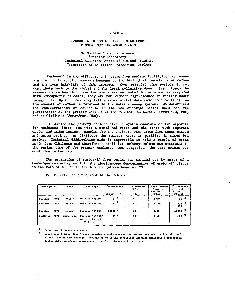
- 268 -
CARBON-14 IN ION EXCHANGE RESINS FROMFINNISH NUCLEAR POWER PLANTS
M. Snellman* and L. Salonen+
*Reactor Laboratory,Technical Research Centre of Finland, Finland+Instltute of Radiation Protection, Finland
Carbon-14 in the effluents and wastes from nuclear facilities has becomea matter of increasing concern because of the biological importance of carbonand the long half-life of this isotope* Over extended time periods it maycontribute both to the global and the local collective dose. Even though theamounts of carbon-14 in reactor waste are estimated to be minor as comparedwith atmospheric releases, they are not without significance in reactor wastemanagement. Up till now very little experimental data have been available onthe amounts of carbon-14 retained in the water cleanup system. We determinedthe concentrations of carbon-14 in the ion exchange resins used for thepurification ox the primary coolant of the reactors in Loviisa (VVER-440, PWR)and at Olkiluoto (Asea-Atom, BWR).
In Loviisa the primary coolant cleanup system consists of two separateion exchanger lines; one with a mixed-bed resin and the other with separatecation and anion resins > Samples for the analysis were taken from spent cationand anion resins. At Olkiluoto the reactor water is purified in mixed bedresins. Technical difficulties made it impossible to take a sample of spentresin from Olkiluoto and therefore a small ion exchange column was connected tothe outlet line of the primary coolant. For comparison the same column wasused also in Loviisa.
The separation of carbon-14 from resins was carried out by means of atechnique rendering possible the simultaneous determination of carbon-14 eitherin the form of CO2 or in the form of hydrocarbons and CO.
The results are summarized in the table.
Powej? plant
Loviisa (PKRl
Loviiaa (PWR)
Loviisa (PWR)
Ctailuoto (BWR)
Resin
cation
anion
anion
mixed bed
Resin type
Duollte ARC 315
Duolite SRA 366
Duolite ARA 366
Duollte ARA 366/
Duolite ARC 315- 2 : 1
14C-activlty
(JcBa/kq w w t )
22 »
393 »
12600 21
40 2>
In form of14COj
(»)
95
99
29
93
Total amountof spentresins(kq/a)
1200
1100
1100
4480
C-contentof spentresins(MBq/a)
26 !»
• 432 I !
13900 2 )
179 2>
2)determined from a spent resin
determined from a "fresh" resin samples a small ion exchange column was connected to the outlet
line of the primary coolant. Scaling up to actual conditions was made utilizing a correction
factor which considers resin masses, sampling times and flow rates.

- 269 -
The following conclusions can be drawn:
- The specific activity of carbon-14 in the spent anion resins from Loviisa is18-fold as compared to the activity of spent cation resin this owing to the5 percent impurity of carbonate in the anion resin. The prevailing form ofcarbon-14 in spent resin is C02»
- The specific activity is carbon-14 in the "fresh" anion resin sample fromLoviisa is 32-fold as compared to the activity of spent anion resin. Thedifference arises mainly from the great tendency towards a loss of carbon-14during the handling and sampling of spent resin and from the resin's poorretention capacity for carbon-14 during its period of usage. In fresh resinsonly 29% of carbon-14 came as CO2 which stands in agreement with theresults from carbon-14 activity determination in the primary coolant. In thecoolant only 1% of carbon-14 was as CC>2«
• The specific activity of carbon-14 in fresh resin from Loviisa is about320-fold as compared to that from Olkiluoto. The difference may be explainedby the reac'or type but it may also be an indication of a higher productionrate of carboti-14 in Loviisa, where N2H4 and NH4H are used in theprimary coolant.
The carbon-14 content of spent resins in Loviisa is 0.7% of the amount ofcarbon-14 produced in the coolant, if the carbon-14 production rate in thecoo]ant is assumed to be 185 GBq/GW(e).a. This percentage would be muchhigher if it would be calculated on the basis of the "fresh" resin and thuswould be an overestimate.
The carbon-14 content of the resins from Olkiluoto is 0.1% of the amount ofcarbon-14 produced in the coolant, if the carbon-14 production rate in thecoolant is assumed to be 300 GBq/GW(e).a. The value is based on the deter-minations of "fresh" resin and may also be an overestimate. We analyzed aspent resin sample from Oskarshamn (Asea-Atom, BWR), its specific activitywas 18 kBq/kg of wet weight. This is 55% lower than the activity of the"fresh" resin from Olkiluoto.
The final carbon-14 content in the disposed reactor waste might be lower thanthe concent obtained in our study, since the carbon-14 may escape from thespent resin in the final management.

- 270 -
AN OVERVIEW OF THE ONTARIO HYDROCARBON-14 CONTROL PROGRAM
R.R. Stasko and G.A. VivianOntario Hydro
Toronto, Ontario
INTRODUCTION
Carbon-14 has a half-life of 5,730 years, and decays by emitting alow energy beta particle (4.67 keV average). It is found in tracequantities in the natural environment, usually in the form of carbondioxide, carbonates and organic compounds. The natural production rateis approximately 38,000 Ci/yr, and occurs primarily in the upperatmosphere via the action of cosmic rays on nitrogen.
C-14 is also produced in nuclear reactors, principally by neutronactivation of nitrogen-14, oxygen-17, and carbon-13. Due to designdifferences, CANDU reactors produce significantly more C-14 than lightwater reactors. However, the contribution to the global inventory ofC-14 is still small, as indicated below.
SOURCE MCi
Natural 300Nuclear weapons testing 7Nuclear reactors (excepting Ontario Hydro) 0.2Ontario Hydro nuclear reactors 0*04(to 1995 with no control measure)
The annual dose each individual receives from natural and man-madecarbon-14 is about 1.3 millirems. Reactor-produced carbon-14 contributesabout 0.1 percent of this or 0.0013 millirems based on its eventualdistribution in the atmosphere, biosphere and ocean. Thus, even if nocarbon-14 control measures are implemented, nuclear reactors contributean extremely small fraction of radiation exposure. However,consideration of the environmental impact of carbon-14 must include notonly the local immediate exposure but also the long-term regional andworld exposure.
PROGRAM OBJECTIVES
Ontario Hydro has recognized the potential significance ofcarbon-14 build-up due to its longevity, and has, therefore, embarked ona program with the following objectives:
establishing the level of present emissions from nuclear stationsand assessing their impacts;making design changes to reduce emissions wherever appropriate;conducting a research and development program on additional controlmechanisms, and determining where they should be implemented.

- 271 -
DATA COLLECTION AND COMPLIANCE MONITORING
In order to determine if C-14 control measures are necessary,emissions data must be compared to acceptable release criteria-.Accordingly, Ontario Hydro has embarked on a program of data collectionwhich establishes a database of representative C-14 emissions. Inaddition, a document which defines the basis for C-14 emissionlimits ' -) has been submitted to and approved by the Atomic EnergyControl Board.
Based on tentative station derived emission limits (DEL) arisingfrom this document, current emissions performance is summarized in Table1.
Various experimental compliance monitors have been installed andtested at each of the nuclear stations. The test program is essentiallycomplete and indicates that sodium hydroxide bubblers are optimal forcompliance monitoring since they are simple, reliable and can functionwell at ambient temperatures unlike the dry absorbers also tested.
Liquid releases of C-14 are not considered significant at thistime. However, if monitors for aqueous C-14 releases are required, it isanticipated that a liquid scintillation counting solution whichefficiently absorbs carbon dioxide would be used.
PICKERING B ANNOLUS GAS CONVERSION
In CANDU reactors, the major mechanism for C-14 production isactivation of 0-17 in the moderator D,0- However, because thePickering A units have nitrogen in the fuel channel/calandria tubeannulus gas (unlike other stations utilizing CO2), there is anothersignificant production problem via N-14 activation.
In order to eliminate this mode of C-14 production, an annulus gasconversion is presently being engineered for Pickering A. Initially,only units 1 and 2 will be converted since annulus gas leaks associatedwith units 3 and 4 (resulting from pressure tube replacements) may createan occupational hazard through elevated CO2 levels.
REMOVAL TECHNOLOGY DEVELOPMENT
The C-14 that is produced by the activation of oxygen-17 in themoderator D2O partitions itself between the moderator water (asdissolved carbonate) and the helium cover gas (as CO2). While much ofthe dissolved carbonate is removed via moderator purification systems, asignificant portion is transferred into the cover gas, which has greaterpotential for escape to the environment. A prototype carbon-14 removalsystem for the helium cover gas has been developed and is currentlyoperating in the laboratory. Carbon-14, as carbon dioxide, is renovedfrom the gas using calcium hydroxide according to the following reaction:
Ca(0H)2 + C02 ly. CaC03 + H20

- 272 -
The product is a solid, stable carbonate species which may besuitable for disposal. The system employs a column filled with up to 5kilograms of calcium hydroxide. This cell operates at 25° Celsius and 35kilopascals (g) and processes a flowrate of 2.5 litres per second.Studies has indicated a greater than 95 percent efficiency for carbon-.l4absorption. Five kilograms of calcium hydroxide can absorb approximately1.4 kilograms of carbon dioxide which corresponds tc 1,900 curies ofcarbon-14•
This prototype would probably provide the basis for any futureinstallations if it is determined that C-14 removal from moderator covergas is necessary.
REFERENCE
1) D> J. Gorman, "The Basis for Derived Emission Limits for Carbon-14in Ontario Hydro Nuclear Power Stations," Ontario Hydro ReportSSD-81-3, 1981 October.
TABLE 1
CARBON-14 GASEOUS EMISSIONS
Average C-14 Provisional DEL Release Expressed Average ProportionSTATION Release Rate for Airborne as % Provisional of C-14 Released as
(Ci/wk) Emissions (Ci/wk) DSL 14 __ (in %)"2
PickeringNGS-A
BruceNGS-A
Douglas PtNGS
NPD
14.5
1.37
0.37
0.27
1,400
1,090
1,770
18,000
1.0
0.13
0.02
0.002
74
76
82
99

- 273 -
CANADIAN ENVIRONMENTAL RESEARCH FOR NUCLEARWASTE MANAGEMENT
S.L. IversonAtomic Energy of Canada Limited Research Company
Whiteshell Nuclear Research EstablishmentPinawa, Manitoba, Canada ROE 1L0
The environmental, health and safety aspects of nuclear wastemanagement cover a wide range of topics, most of which I will only touch onin this presentation. Operational safety and worker health, and theimmediate effects of radioactive releases on the environment are wellunderstood, and have been addressed quite successfully in the past. Ourunderstanding continues to be improved by specific research programs at thesame time as industrial safety and assessment practices are improving. Thesame is generally true for management and disposal of the short-livedfission and activation products arising from reprocessing or medical andindustrial uses. Some wastes contain long-lived materials and as thelength of time the wastes must be contained increases, diversity of opinionon appropriate disposal methods, safety, etc. also increases. There is awide range of views on the disposal of long-lived radioactive materialssuch as actinides and some fission products in irradiated fuel, andnaturally radioactive materials from uranium mining.
Opinions range from suggestions that such materials are not a problembecause of their low specific activity, low abundance or low toxicity incomparison to non-radioactive materials, to views that we cannot safelymanage or dispose of such materials or even conduct a meaningful safety orenvironmental assessment of a long-term disposal method. Support for thefirst opinion is drawn from concepts and data developed to assessshort-term facilities and practices. Those supporting the second point ofview cite the long time spans and large uncertainty associated with thefuture, the need to understand slow environmental processes adequately andthe need to deal in general with areas of imperfect knowledge.
Without making a judgement about the detail or time period that anassessment of the environmental and health effect of a practice such asdisposal of irradiated nuclear fuel will consider, I wish to outline someof the work we are doing, and planning, to improve our ability to assessfuture impacts. Most of this work is being done in the EnvironmentalResearch Branches of AECL's Whiteshell and Chalk River establishments andis sponsored by the Canadian Nuclear Fuel Waste Management Program.
Essentially all of the concepts for disposal involve emplacement ingeological formations of some type. Proposals range from near surface"covering" of tailing piles to emplacement of irradiated fuel deep instable rock. The Canadian concept for disposal of irradiated fuel involvesemplacement deep in crystalline rock formations on the Canadian Shield. Inmost cases, radionuclides from these disposal vaults will result in dosesto man only if they are transported to the biosphere by groundwater and, inthe case of irradiated fuel, this is the only feasible pathway. Transportby groundwater through rock formations is being studied intensively in theApplied Geoscience Branch at WNRE and in other places, but from anenvironmental perspective, the actual point of discharge from the rockformation significantly affects the impact.

J- 274 -
The most important characteristics of the discharge point are volumeof water available for immediate dilution, presence of materials orchemical conditions that could immediately trap the contaminant, and man'suse of the area. We need to know where major groundwater systems of theCanadian Shield discharge, if it is a safe generalization that dischargewill occur in the regional low, and if regional lows on the Shield arenormally occupied by sizeable rivers and lakes. Can the salt in the deepsaline groundwaters be used as a tracer to tell us something about wherethey discharge? Answers to these and other questions will be forthcomingin the next few years.
If radionuclides reach the surface environment, how long do theyremain mobile and available before reaching a "sink"? Can local orregional sinks exist in the long term or are deep oceans the onlymeaningful sinks? These questions have not been particularly importantwhen assessing short-lived radionuclides because radioactive decay has beenaS3used to be the most important process decreasing environmentalconcentrations, but they clearly become important when assessing the impactof very long-lived or stable materials. Studies of the shield soils andsoil-forming and erosion processes will shed light on the long-termdirection of movement and fate of chemical species in the parent material,and may provide enough information on soil geochemistry so behaviour ofother elements can be predicted. Soil-plant interactions are important inthis regard, because plants can strongly affect the soil chemistry whilethe soil determines the type of plants which will grow and thus thepotential pathways to man. A related area, which is beginning to beaddressed, is the importance of aquatic sediments and the extent to whichthey form long-term sinks.
The processes considered thus far relate to predicting concentrationin some part of the environment, and from this, the radiation dose to mancan be estimated. Current dose assessments use estimates derived fromsurveys of the food man eats, the water he drinks, the air he breathes andthe amount of time he is exposed to various external sources. Much of thedata currently used is highly specific and thus pertinent only t ourpresent cultural pattern. To minimize this limitation, models and data arebeing developed that rely on basic, general processes. For example,estimates of man's food intake can be based on his requirement formetabolic energy, as can the food intake of the animals that form part ofhis food chain.
The long time spans and associated uncertainties involved in nuclearwaste management assessments make the use of probabilistic methodsparticularly attractive, and such methods are being applied. To useprobabilistic methods, the environmental scientist must specify parameterdistributions rather than mean or conservative values as in the past. Weneed a general approach to parameter distributions and, while there havebeen suggestions that many are distributed log-normally, this question willclearly receive more attention in the future. An area where we are onlystarting to perceive some of the questions is that of the correlationbetween parameters and what it implies in terms of model structure and

J- 275 -
parameter specification. Estimated doses from radionuclides released bywaste management practices may be compared to natural background to gainperspective as to their importance or likely effect, so we may need to knowmore about natural background radiation and its variation.
My purpose has been to provide a context for understanding currentresearch and future developments in the exciting new field of assessingsmall environmental and health effects in the distant future. In thefollowing papers, and over the next few years, you will see the detailsbeginning to emerge. While we cannot forecast the future precisely, we canextrapolate into it meaningfully by observing and understanding theprocesses that have produced the natural environment as it now exists.
- 276 -
RADIOECOLOGY AND WASTE MANAGEMENT
A. GraubyHead of Environmental Research Service
French Atomic Energy CommissionCadarache, France
Treatment and disposal of radioactive waste represent for the Environ-mental Protection specialist, not only a normal continuation of radioecologi-cal research, but also the need to reevaluate the impact assessment method-ology. Thus, for the environment of a disposal site, in both fields ofresearch and development, a new concept in assessment studies has to beused*
In research, only those long-lived radionuclides, actinides, Tc,1-129, Ra, Th, U, etc.. and those with global diffusion (H-3, I, Tc) areinteresting. Likewise in transfer paths and mechanisms, research is orientedtowards the long term evolution of the physico-chemical forms of radio-nuclides under the action of bacteriological and chemical agents, and towardsthe slow dynamics of transfer through artificial barriers, geological and thebiological compartment, towards the space notion of the concerned environmentthat has different dimensions than the other aspects of the fuel cycle(mining, milling, power production, reprocessing).
In development, the application of radioecological research todisposal site selection, even though it uses the same methodology as for theother types of nuclear facilities, must integrate the new parameters tied tothe specific characteristics of this type of site. The author will describethe radioecological methods used in site selection specifying these comple-ments:
- More detailed environmental analysis of the organic and mineral constitu-ents of the soils and water, soil formation processes, bacterial activity,the dynamic interrelationship - precipitations - soil - ground water. Thewhole of these parameters sets the evolution and the transport of mineralelements on a long term basis.
- A more complete integration of radioecological research data on the trans-fer of long-lived radionuclides in site selection, thus reducing the use ofmodels.
The author proposes for the assessment of environmental impacts of wastedisposal, a revision of procedures, making a more important use of radioeco-logical data in waste management. This is to avoid the use of too theoreti-cal models on the long-term processes and a too large distortion in healthrisk assessment and their consequences on future generations.

J- 277 -
RADIOÉCOLOGIE ET LA GESTION DES DÉCHETS RADIOACTIFS
A. GraubyChef du Service d'Etudes et de Recherches
sur l'EnvironnementCommissariat a l'Energie Atomique
Cadarache, France
Le traitement et le stockage des déchets représentent pour lesspécialistes de la Protection de l'Environnement à la fois le prolongementnormal de leur action en matière de recherches radioécologiques maiségalement l'obligation de situer en termes différents les problèmes d'impact.Ainsi, pour l'environnement des sites de stockage, aux deux niveaux de larecherche et du développement, une nouvelle conception des études doit êtreutilisée.
En terme de recherche, seuls les radioéléments â vie longue,actinides, Te, 1-129, Ra, Th, U, etc.. et les radioéléments à diffusionglobale (H-3, I, Te) présentent de l'intérêt. De même au niveau des voies etdes processus de transfert, les études s'orientent vers les mécanismesd'évolution â long terme des formes physico-chimiques des radioéléments sousl'action des agents chimiques et bactériens, vers une dynamique lente destransferts à travers les barrières artificielles, géologiques et lecompartiment biologique, vers la notion d'espace à donner à l'environnementconcerné qui n'a plus les mêmes dimensions que celui des autres étapes ducycle du combustible (Mine, métallurgie, électronucléaire, reprocessing).
En terme de développement, l'application des recherches radioécologi-ques aux choix des sites de stockage, bien que faisant appel aux méthodolo-gies utilisées pour les autres types de site Industriel Nucléaire, doitobligatoirement intégrer des nouveaux paramètres liés aux caractèresspécifiques de ce type de site. Ainsi, l'auteur rappelle les méthodes radio-écologiques d'étude et de choix des sites nucléaires et précise les complé-ments nécessaires:
- Analyse de l'environnement plus développée sur les constituants minéraux etorganiques des sols et des eaux, sur les processus de pëdogénêse, surl'activité bactérienne, sur les relations dynamiques du système précipita-tions-sols-nappes. Cet ensemble de paramètres détermine l'évolution et letransport des éléments minéraux â l'échelle du long terme.
- Incorporation plus active dans l'étude du site des résultats des recherchesradioécologiques sur le transfert des radionucléides â vie longue avec parvoie de conséquence une utilisation modérée des modèles.
Ainsi, l'auteur propose pour l'évaluation de l'impact sur l'environne-ment du stockage des déchets radioactifs une révision de procédure au profitd'une exploitation plus importante des données radioécologiques adaptées auproblème du "WASTE MANAGEMENT". Cette démarche a pour but d'éviter par unemodélisation trop théorique de processus à long terme une distorsion tropgrande dans l'évaluation des risques sanitaires avec ses conséquences pourles générations futures.

J- 278 -
A MODEL TO CALCULATE DOSES FROM IODINE-129 ON A LOCAL, REGIONALAND GLOBAL SCALE FROM THE PROPOSED CANADIAN HIGH LEVEL WASTE VAULT
J.R. Johnson , D.M. Wuschke* and J.G. VanHeterenAtomic Energy of Canada LimitedChalk River Nuclear Laboratories
Chalk River, Ontario
*Whiteshell Nuclear Research EstablishmentPinawa, Manitoba
A model to describe the retention and distribution of iodine-129in the environment for the purpose of calculating doses has beendeveloped (Fig. 1). It is an extension of Kocher's model (1) whichdescribed the global distribution and retention of 129i after anatmospheric release. The present model was developed to describethe local, regional and global distributions and retention of Iafter release to water from the deep rock vault that is used in thecurrent Canadian assessment study (2). Iodine escaping from the vaultis assumed initially to enter the local surface water from which itcan be transferred to the various local compartments (see Fig. 1) orto regional surface water. Transfers of 12 I from the local toregional areas can also take place via air and underground water(saturated zone). Similarly, 129i is distributed in the regionalarea and transfers from this area to the ocean air and ocean mixinglayer are via air, surface water and saturated zone water. Once lZ9iis in the ocean air and the ocean mixed layer, it is available forre-distribution to land masses through ocean air.
Figure 1 describes a first order compartment model; that is,the transfer between one compartment and another (arrows of Fig. 1)is proportional to the amount of 1 2 9I in the compartment that thearrow is leaving. Nominal values for these rate constants and forthe concentration of stable iodine in each compartment were calculatedby assuming that the local and regional values were equal to theglobal averages given by Kocher (1). For this purpose, the localarea was assumed to have an area of 101* km2 with a population of iO1*,and the regional area an area of 106 km2 with a population of 107.The global population is assumed to be 1010. A study is now underwayto obtain the rate constants and stable iodine concentrations consistentwith the available information in the Canadian Shield and the GreatLakes system.
The rate of discharge of 1 2 9I to the local surface water thatwas used, as obtained from a single run with the SYVAC computercode (2) is shown in Fig. 2. To obtain this output, it was assumedthat the vault contained 3.5 x 10⁸ kg of spent fuel in 2.46 x 10s
containers. The inventory of 129i Was 9.1 x 10* GBq, of which afraction 7 x 10~3 was in the fuel gaps and would be releasedimmediately to the water in the vault when a container failed. The

- 279 -
remaining 1 2 9I would be released as the fuel dissolved. The 12.3Ireleased into the vault water is assumed to be transported in waterto the surface with no retardation, in this case a low value of 360years. In this particular SYVAC run, the fuel container failurerate was assumed to have a gaussian frequency distribution with amean time post-closure 11 = 3.5 x 10 3 a and standard deviationa = 0.5 u.
A computer code utilizing the FORSIM package (3) was writtento calculate adult and infant dose rates, and collective dosecommitments, by calculating the specific activity of theiodine in the compartments given in Fig. 1, and thereby calculatingan average specific activity for all iodine intakes using the dietassumed by Kocher (1). The results of these calculations for adultsare given in Fig. 3. The maximum local individual thyroid dose of10 7 Sv a 1 is about a factor of 101* below the maximum total doseand approximately equal to the "most likely" total dose as calculatedby the SYVAC computer code (2). Individual dose rates to infants(one year old) are about a factor of 4 below those for adults. Workis underway to see how the assumptions made about the distributionand retention in the environment will affect the dose rates andcollective dose commitment.
This work is the first attempt at calculating doses due toreleases from the proposed Canadian disposal vault on a local, regionaland global scale. It is also one of the few studies involvingreleases of 1 2 9i into ground water, rather than the atmosphere, andfor continuous long-term releases rather than those of duration oneyear or less. The final paper will contain results obtained usingthe rate parameters and stable iodine concentrations derived for usein the Canadian Shield and Great Lakes systems, and will report onthe sensitivity of the calculated doses to the model compartmentsand parameters.
REFERENCES
(1) D.C. Kocher, "A Dynamic Model of the Global Iodine Cycle forThe Estimation of Dose to the World Populations from Releasesof Iodine-129 to the Environment." Oak Ridge NationalLaboratory, Report ORNL/NUREG-59 (1979).
(2) D.M. Wuschke, et al., "Environmental and Safety AssessmentStudies for Nuclear Fuel Waste Management, Volume 3: Post-Closure Assessment." Atomic Energy of Canada Limited, ReportTR-127-3 (1981).
(3) M.B. Carver, et al., "Forsim VI - Fortran Oriented DistributionSystem Simulation Package for Partial and/or OrdinaryDifferential Equation User's Manual." Atomic Energy of CanadaLimited, Report AECL-5821 (1978).

FROM_
VAULT
AIR
SURFACEWATER
UNSATURATED!ZONESOIL
WATER
SATURATED!ZONESOIL
WATER
BIOSPHERE!
SOILSOLIDS
UNSATURATED!ZONESOILWATER
SATURATEDZONESOILWATER
LOCAL DISTRIBUTION j REGIONAL DISTRIBUTION
SHALLOWSUBSURFACE
DEEP[SUBSURFACE!
GLOBALLANDAIR
SURFACEWATER
UNSATURATED]ZONESOIL
WATER
SATURATEDZONESOIL
WATER
BIOSPHERE
SOILSOLIDS
REVISED GLOBAL MODEL OF KOCHER
houo
FIGURE 1. The model used to describe distribution and retention of iodine on a localregional and global scale .

'o
o*CQ
UJh-
(X.
SC
HA
RG
E
o
a>
«02
10
1
10- •
S0-2
I 0 ' 3
1— ^,
—
—
y^ i
r 1
\FROM I 2 9 I IN FUEL GAP
•
_
1 FROM FUEL DISSOLUTION
I -
1 I 1I03 I04 I0 5
TIME SINCE CLOSURE (YEARS)10'
00
FIGURE 2. Assumed rate of discharge of 129I into the local surface water from the deeprock vault.

INDIVIDUAL THYROID DOSE EQUIVALENT RATE (Svo" 1 )
gg1
it8-39 o>(-• O
iQ 10• IB
u>H- O3 O
S8n> r t
0.SP- (0[0
&S,n n>iQ aID ft» %•
B> a>a> aoo D>H> a>
u>
to n• PI
oeH-1
S»
ACCUMULATED COLLECTIVE EFFECTIVE DOSE EQUIVALENT (Man-Sv)

- 283 -
ECOLOGICAL VECTORS OF RADIONUCLIDE TRANSPORT AT A SOLIDRADIOACTIVE WASTE DISPOSAL FACILITY IN SOUTHEASTERN IDAHO
W. John Arthur and 0. Doyle MarkhamU.S. Department of Energy
Idaho National Engineering LabatoryIdaho Falls, Idaho, USA
Since 1952, the Idaho National Engineering Labatory (INEL) SubsurfaceDisposal Area (SDA) has been used for shallow land disposal of solid low-level radioactive wastes. To date approximately 8.2 x 10^ Curies (Ci) ofactivation, fission, and transuranic contaminated wastes have been disposedat the 36 ha SDA. Generally, radioactive wastes are disposed in pits ortrenches averaging 4 m deep which are covered by a mimimum of 0.6 m soil toisolate the waste and reduce radiation exposures at the ground surface.Due to deterioration of some earlier disposed waste containers anddegradation of uncontained wastes, radionuclide contamination has occurredin some SDA subsurface soils (1). Some SDA surface soils also containelevated levels of transuranic radionuclides (2).
Radioecological research is being conducted at the SDA to assess theimportance of various environmental pathways in transporting radionuclidesfrom the waste disposal facility. Principal objectives of this researchare to define and model the quantity of radionuclides transported byvarious ecosystem components and to determine the impact of subsurfacedisposal of radioactive wastes on biotic species inhabiting the area.
Initial observations indicated that cottontail rabbits and rodentswere the most frequently occurring wildlife at the SDA, therefore,ecological studies focused on these species* Concentrations of 9^1 3 7Cs, 238Pu, 239' 240Pu, and 241Am in deer mice at the SDA weresignificantly greater than control area samples* By relating theradionuclide concentrations in deer mice tissues to data obtained on smallmammal local movements and density (3), 2 uCi of radioactivity wereestimated to occur in the SDA deer mice population as compared to 0.001 uCiin control area mice. Radionuclide concentrations detected in other rodentspecies, cottontail rabbits, sage grouse, mourning doves, and insectscollected at the SDA were all lower than thoss concentrations in deer micetissues.
Since coyotes were one of the most commonly occuring predatorialspecies in the SDA area, coyote fecal sraiples were collected and analyzedfor radionuclides. Elevated 2<*lAm concentrations in fecal samplescollected around the SDA were attributed to ingestion of contaminated smallmammals; however, the total inventory of radioactivity eliminated by coyotefeces within a 6.3 km radius of the SDA was only four times greater thanthe quantity eliminated at a control area (4). Recently initiated raptorresearch projects will examine predator-prey interactions at the SDA andwill attempt to quantify radionuclide transport by these species.
Radiation dose rates over those SDA areas used by wildlife rangedfrom 0.4 to 0.3 mrad/day. Packets containing two thermoluminescentdosimeter chips were surgically implanted in deer mice and kangaroo rats

j- 284 -
inhabiting the SDA. Based on recovery of 361 of 681 packets implanted,mean radiation dose rates received by deer mice (364 inrad/day) weresignificantly greater than mean radiation dose rates received by kangaroorats (9.9 mrad/day). Statistical comparisons of the radiation dose ratesreceived by individual small mammals to the ambient radiation dose rates onthe SDA surface indicated 48 percent of the small mammal population hadencountered areas of disposed gamma-emitting radioactive waste orcontaminated soil- Concurrent with the dosimetry study, research wasconducted to determine potential effects of chronic radiation exposure onsmall mammals inhabiting the SDA (5). Animals examined for hematopoieticsystem changes, pathological changes, vital and reproductive organ lesions,and lymphocyte and chromosomal damage showed no effects attributable toradiation exposure.
Soil burrowing by small mammals in the SDA is a vertical mode ofradionuclide transport. Between July 1977 and July 1979, an estimated12450 kg of soil were excavated to the SDA surface by small mammals (6).Plutonium-239, 240, 241Am, and l^7Cs concentrations in excavated soilswere significantly greater than the concentrations of these nuclides insurface soils over several SDA areas. The inventory of 66 pCi (90Sr,1 3 7Cs, 238Pu, 239' 240Pu and 241Am) estimated to occur in SDAexcavated soils was three times greater than the nuclide inventory incontrol area soil excavations.
Elevated 238Pu, 239' 240Pu, and 231Ara concentrations were alsodetected in crested wheatgrass and Russian thistle samples collected at theSDA. Over a one-year period a total of 77 yd was estimated to occur inSDA vegetation as compared to 17 uCi in a control area having a similarvegetation composition and biomass to the SDA (7). Comparisons ofvegetation radionuclide concentrations at several SDA areas havingdifferent soil cover depths over disposed waste will provide information toassess the effectiveness of these covers in minimizing vegetativeradionuclide uptake-
Radloecological research conducted at the INBL Subsurface DisposalArea has characterized and quantified various ecological vectors ofradionuclide transport at a shallow land radioactive waste disposal area.Even though soil, vegetation, and small animal tissue samples collected atthe SDA had elevated radionuclide concentrations, none of these ecologicalvectors contributed appreciable quantities of radioactive contamination tothe environment surrounding the SDA. It is doubtful any environmentalconsequences occur as a result of these radionuclide transport mechanisms.More important may be the effects of factors such as small mammal soilburrowing and deep rooting vegetation on the integrity of soil coversimplaced over the disposed waste. Research currently being initiated atthe SDA will relate results of these radioecological studies to managementconsiderations associated with stabilizing shallow land radioactive wastedisposal sites. Emphasis will be placed on selecting native soil coversthat will minimize vegetation and small mammal intrusion into disposedradioactive waste at the INEL.

J- 285 -
REFERENCES
1. D.H. Card* "Early Waste Retrieval Interim Report" -X!ree-JlO47. Natl.Tech. Inf. Serv., Springfield, VA (1977).
2. J.L. Harness and R.W. Passmore. "1974 Qnsite EnvironmentalSurveillance Report for the INEL Radioactive Waste ManagementComplex". Tree-1014. Natl. Tech. Inf. Serv., Springfield, VA (1976).
3. C.R. Groves. "The Ecology of Small Mammals on the Subsurface DisposalArea, Idaho National Engineering Laboratory Site". M.S. thesis. IdahoState University. Ebcatello, Idaho, 1981.
4. W.J. Arthur and O.D. Harkham. "Radionuclide Export and Elimination byCoyotes at Two Radioactive Waste Disposal Areas in SoutheasternIdaho". J. Health Phys. (In press).
5. L.M. Evenson. "Systemic Effects of Radiation Exposure on RodentsInhabiting Liquid and Solid Radioactive Waste Disposal Areas".M.S. Ihesis. University of Idaho. Moscow, ISado (1981).
6. W.J. Arthur and O.D. Markhanw "Small Mammal Soil Burrowing as aRadionuclide Transport Vector at a Radioactive Waste Disposal Area inSoutheastern Idaho". J. Env. Qual. (Submitted).
7. W.J. Arthur. "Radionuclide Concentrations in Vegetation at a SolidRadioactive Waste. Disposal Area in Southeastern Idaho". J. Env. Qual.(In press).

J- 286 -
A CONTAMINATION ASSESSMENT STUDY FORGENTILLY WASTE STORAGE FACILITIES
C. Marche*, C. Schneeberger**, S. Trussart+, M. Lavallee+
* Ecole Polytechnique, Montreal, Canada**Geos Inc., Montreal, Canada
+Hydro Quebec, Montreal, Canada
INTRODUCTION
The solid radioactive waste storage area of the Gentilly Nuclear PowerGenerating Station is located in the St-Lawrence Biver flood plain and abovean underground water table which serves as a source of drinking water for afew homes. In these conditions, large quantities of fresh water may becomequickly polluted by the dispersal of contaminated water originating from thewaste storage area. In order to insure that the local population is ade-quately protected in case of rupture of the engineered structure of the wastestorage area, Hydro Quebec undertook a study on the dispersion-convection ofradioactive contaminants in the surface runoff system and in the undergroundwater tabis in normal conditions and in case of flooding.
GENERAL CONDITIONS
The storage facilities are designed for low to intermediate levelwastes. They are planned to be used for the expected 30 years lifetime ofthe reactors. At that time 251 TBq of 13'Cs, 2.5 TBq of 90Sr and20 TBq of 3H will have been stored in the storage facilities. These valuesare used without considering any decay factor to determine the initialconcentration of radionuclide. This initial concentration is the source ofcontamination to be considered in the study.
The source of concentration is assumed to remain constant for a 2 yearperiod. Such a period results from numerous discussions amongst the differ-ent specialists involved. It represents the period of time between theoccurence of the leak and the date at which all the radioactive material willhave been removed from the site. This 2 year period is thus aiming to repre-sent the detection period, the organization of the remedial works and theircompletion. It is thought that such a period is a very conservative esti-mate.
Both assessment studies i.e. surface and groundwater analyses, arebased on similar assumptions which all are believed to be very conservative.
SURFACE WATER ANALYSIS
The purpose of this first study is to determine the radionuclideconcentrations in the surface water, assuming that a flood of the St-LawrenceRiver occurs simultaneously with the accident.
The local flow pattern is related to the river discharge and tides.The maximal spring tide observed at a neighbouring station is 1.22 m high andis mainly semi-diurnal. From hydrological studies the one hundred year flood

- 287 -
is estimated to reach elevation +7.0 m above the geodetic datum. The typicalunsteady flow patterns have been defined on the basis of these conditions andby using a two dimensional finite element model.
These flow conditions would flood the Hydro Quebec property as shownin Figure 1. Gl and G2 powerplants as well as the waste storage area wouldnot be flooded. The landfill is considered as a source of constant radio-nuclide concentration in the flooded area. The dispersion of the radio-nuclide has been computed by a two dimensional finite element dispersionmodel taking into account the velocity fields previously computed. Typicalresults are presented in Figure 1 to show relative strontium concentrationover the site at high tide.
The results must be discussed separately for each radionuclide. Theconcentration of tritium calculated in all cases is always lower than themaximum permissible concentration in water for a member of the public. Forcesium, the concentration would be higher than the maximum permissibleconcentration in the vicinity of the landfill but a fast dilution of thecontaminant is observed at a short distance from it. Finally it appears thatstrontium could be the most critical radionuclide but, in this case, theassumption that the initial concentration in the landfill could remainconstant during a long time (2 years) is considered unrealistic because thetotal quantities of strontium in the water would become higher than the totalstored quantity.
GROUNDWATER ANALYSIS
The purpose of this second study is to determine the radionuclideconcentration in groundwater.
A finite element numerical model that permits evaluation of the migra-tion of a pollutant in contact with the groundwater has been developed. Theprogram takes into account the dispersion-convection phenomenon, the adsorp-tion of radionuclides by the soil particles and the radioactive decay. Thedistribution coefficient Kd and the dispersion coefficient D are the relevantparameters in the analysis.
Simple rules to correlate these parameters to the identificationcharacteristics of the soil have been developed.
As shown in Figure 2, the distribution coefficient of soils for"^Sr is directly related to the percentage of particles smaller than74 ym. The dispersion coefficient of the soil is a function of its grain sizecharac teri stic s.
Typical results of the 90gr an<| 3H concentrations calculated 30years after the hypothetical accident are presented in Figure 3.
CONCLUSIONS
The approach used in this study takes into account all the relevantphenomena involved in the radionuclide migration process, the specificgeometry of the site and a failure scenario initially defined. In such cases

- 288 -
mathematical models have been extensively used to define the general patternof the induced contamination. Based on this pattern an evaluation of theimpact of the local population becomes feasible.

S c a l e :
toooo
0 200 400m
FIGURE 1 Relative Strontium ConcentrationsOver The Site At High Tide

- 290 -
5 0 0
100
o
IfM
20 40 60 80 100
of particles smaller than 7 4 pm,
anFIGURE 2 Distribution Coefficient for Sr as a
Function of Soil Grain Size Characteristics

- 291 -
specified concentrationat ground surface
0.0
0.0 0.2 0.4 0.6 0.8 1.0
0 I 2time ,t. years
stratigraphy
0.0
0.5
ao
o
. J ^ — t s 2 yearst=3 years *
-t» 5 years
t* 30 years
i.o μ-v—
1.5
2.0
2.5
maximum depthwere C is over thepermissible value
0.0 0.2 0.4 0.6 0.8 IX)
C/C.
a. TRITIUM b. STRONTIUM
C , computed contaminant concentration
C» t initial contaminant concentrationc adm f permissible contaminant concentration
FIGURE 3 Vertical Propagation of ContaminantDissolved in Groundwater

- 292 -
ANALYSIS OF ATMOSPHERIC PATHWAYS OF EXPOSURE AT JACKPILE MINE
M.H. Momeni, C.E. Dungey, and C.J. RobertsArgonne National Laboratory
Argonne, Illinois, USA
One of the potential health hazards associated with uranium mining isexposure to the radionuclides in the uranium-238 series. The majorsources of radioactivity are materials that are classified as ore if thequality (equivalent U3O3 content) is greater than 0.034% and asinclusive wastes if the quality is less than 0.034. Other materials,such as overburden, are not mineralized, and the concentrations ofradioactivity are comparable to those in soil in the adjacentenvironment. Fugitive dust and atmospheric release of radon (Rn-222)from these mine materials are potential sources of radiation exposure.Among the objectives of uranium-mine reclamation is the reduction ofexposure via atmospheric pathways. This report includes a description ofan analysis of atmospheric pathways of radiation exposure at theJackpile-Paguate mine and a comparison of the calculated airborneconcentrations of particulates, radon, and working level before and afterreclamation.
The Jackpile-Paguate uranium-mining operation consists of surface andsubsurface mines located about 60 km west of Albuquerque, New Mexico.About 1000 hectares of surface area are occupied by the mining complex.About one-third of that area is occupied by open pits, one-third by wastedumps, and one-third by stockpiles, roads, and buildings. Thecharacteristic topography of the area includes rough and broken terrain,broad mesas and plateaus interspersed with deep canyons, dry washes, andbroad valleys. The mine complex is in the Rio Moquino valley, which isoriented NNW to SSE. Because of the complex terrain, the atmospherictransport and diffusion at the site is predominantly thermally driven andis characterized as mountain-valley flows and channeled winds (1,2).The predominant wind direction is from the west. Nocturnal drainagewinds are light, westerly breezes that result from the movement of thecooler and denser air flowing down from the higher terrain to the westand into the mined pits.
The radon release rates prior to reclamation were estimated from thespecific flux (3,4) and surface area of each section of the mine. Theannual releases were conservatively (3-5) estimated to be 3.5 x 10 1 4 Bq(9.5 x 10³ Ci) from the Jackpile pit, 5.6 x 10¹³ Bq (1.5 x 10³ Ci)from the north Paguate pit, and 2.4 x 10 1 4 Bq (6.5 x 10³ Ci) from thesouth Paguate pit. Surface areas of the three pits are, respectively,6.0 km2, 1.1 km2, and 4.0 km2. The particulate flux from fugitivedust was estimated using the methodology described in the UraniumDispersion and Dosimetry (UDAD) computer code developed at ArgonneNational Laboratory(6).

- 293 -
The annual average concentrations of airborne radionuclides attributableto the mines prior to reclamation were calculated for the four townsnearest to the Jackpile-Paguate mines* These values are given inTable 1. The distances are given relative to the confluence of the RioPaguate and .Rio Hoquino drainages near the centre of the mine complex.For purposes of comparison, the airborne concentrations for particulates,radon, and radon daughter products (working level, or WL) attributed tomining operations were calculated by use of both the UDAD code(6) and theUSEPA code ISC{7). Identical input data, including data on localmeteorological conditions, were used with both codes. Results of bothsets of calculations are also shown in Table 1. At all locations exceptBibo, the concentration of radon calculated from the ISC code was 50% to100% larger than that calculated using the UDAD code* The averagemeasured concentrations of radon in the air, including contribution fromnatural background, at Paguate, Bibo, and Laguna have been reported as15.5, 18.5, and 18.9 Bq/m3 (4.2 x 10², 5.0 x 10², and5.1 x 102 pCi/m3), respectively(8). In the region, the naturalbackground radon concentration in air has been measured as 15.1 Bq/m3
(4.08 x 10² pci/m3)(9). This suggest that the prereclamation radonconcentration attributable to mining is less than 4 Bq/m3 at the threelocations. The average measured airborne radium (Ra-226) concentrations,including the natural background contribution, at Paguate, Bibo, and Laguna arereported as 3.5 x 10"5, 5.9 x 10~6, and 4.8 x 10~6 Bq/m3 (9.5 x 10~4,1.6 x 10~4, and 1.3 x lO^pCi/m3), respectively. The thoriumconcentrations at the same locations are 3.5 x 10~5, 3.1 x 10~6, and2.2 x 10"6 Bq/m3 (9.6 x 10~4, 2.2 x 10"4, and 6.0 x 10~5 pCi/m3).
The annual average dose commitments attributable to the Jackpile-Paguatemines prior to reclamation, as calculated vising the UDAD code(6), areshown in Table 2 for the four adjacent towns. As shown in the table, thedose commitments to the residents of Paguate generally are the largest.In all locations, the major exposures are to the lung and bone. Themeasured external gamma exposure in areas immediately adjacent to thedisturbed land is within a range of 60 to 120 mR/yr. The average naturalbackground gamma exposure for the region is approximately 110 mR/yr, witha terrestrial contribution of about 55 mR/yr.
The reclamation plan proposed for the open-pit sections of the minecomplex is to restore the potential flat areas to rangeland and stabilizethe other areas to reduce effects of wind and water erosion. Reclamationwill include surface alteration and dressing with unmineralized material,and conditioning of the topsoil for plant growth. As a result of thereclamation program, the sources of radioactive emissions will be coveredwith unmineralized soil. The vegetation covers that will be establishedby reclamation could control fugitive dust to the same degree that occursin the adjacent, natural environment. Also, because ore was removed andshipped to the mill during mining operations, radon gas only from theinclusive waste will be present to diffuse through the surface cover.This diffusing radon will be attenuated to about the same flux as thenatural background exhalation(5)•

- 294 -
The concentrations of airborne radionuclides attributable to the minesafter reclamation are from resuspension of material deposited during themining operations. The airborne concentrations from the reclaimed areaof the mines will be comparable to those from natural background prior tomining* In addition, because of the mining of high-quality ore, such asthat from the Woodrow outcroppings, major sources or radioactivity havebeen removed and will be replaced with unmineralized materials duringreclamation.
Thus, after reclamation of the mines, the dose commitments fromatmospheric pathways are predicted to be about 20 to 30 times lower thanthose calculated for the prereclamation period, and will be comparable totiie exposures from the natural background' around the Jackpile mine beforemining operations began.
ACKNOWLEDGEMENTS
The authors wish to acknowledge the assistance and reviews of the manuscriptby Marc E. Nelson (Mineral Management Service), Task Force Leader, and theeditorial review of John DePue. This work was performed under the auspicesof the United States Department of the Interior, Mineral Management Service,South Central Region, Albuquerque, New Mexico.

- 295 -
REFERENCES
1. M.H. Homeni "Environment in the Vicinity of Dravan Mill:Characterization of Radioactive Effluents and Airborne RadionuclideConcentrations" U.E. Nuclear Regulatory Commission ReportNUREG/CR-2286, ANL/ES-110 (1981).
2. H.H. Momeni and J.E. Carson "Temporal and Spatial Distribution ofRadon-222 and its Daughters in Complex Terrains" Third JointConference on Applications of Air Pollution Meteorology, Boston,Mass. American Meteorological Society Publication (1980)•
3. D.R. Rayno and C.S. Sabau "Comparison of Radon Flux with Radium-226Content of Ore" in "Radon Release and Dispersion from an Open PitUranium Mine" U.S. Nuclear Regulatory Commission ReportNUREG/CR-1583, ANL/ES-97 (1980).
4. N.D. Kretz and J.B. Lindstrom "Field Measurement of Radon Flux" in"Radon Release and Dispersion from an Open Pit Uranium Mine" U.S.Nuclear Regulatory Commission Report NUREG/CR-1583, ANL/ES-97 (1980).
5. M.H. Momeni et al. "Radiological Impact of Uranium Tailings andAlternatives for Their Management" U.S. Environmental ProtectionAgency Report 520-3-79-003 (1979).
6. M.H, Momeni, Y. Yuan, and A.J. Zielen "The Uranium Dispersion andDosimetry Code" U.S. Nuclear Regulatory Commission ReportNUREG/CR-0553, ANL/ES-72.
7. USEPA "Industrial Source Complex (ICS) Dispersion Model User Guide"U.S. Environmental Agency Report EPA-450/4-790-030 (1979).
8. G.G. Eadie, C.W. Fort, and M.L. Beard "Ambient Airborne RadioactivityMeasurements in the Vicinity of the Jackpile Open Pit Uranium Mine,New Mexico" U.S. Environmental Protection Agency Report ORP/LV-79-2(1979).
9. M.H. Momeni et al. "Radon and Radon-Daughter Concentrations in Airin the Vicinity of the Anaconda Uranium Mill" U.S. Nuclear RegulatoryCommission Report NUREG/CR-1133, ANL/ES-81 (1979).
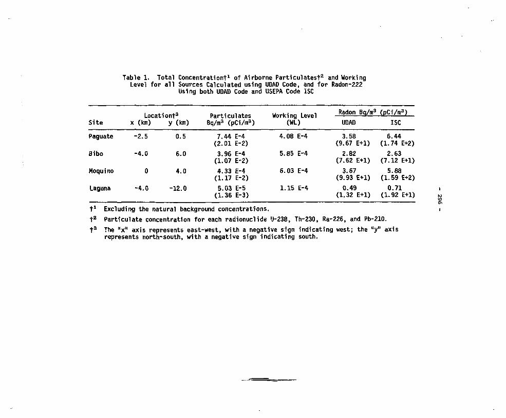
Table 1. Total Concentration"!"1 of Airborne Particulatest2 and WorkingLevel for all Sources Calculated using UDAD Code, and for Radon-222
Using both UDAD Code and USEPA Code ISC
Location*3Site x (km) y (km)
ParticulatesBq/m3 (pCi/m3)
Working Level(WL)
Radon Bq/m3 (pCi/m3)
UDAD ISC
Paguate
Bibo
Moquino
Laguna
-2.
-4.
-4.
5
0
0
0
0.
6.
4.
-12.
5
0
0
0
7.44(2.01
3.96(1.07
4.33(1.17
5.03(1.36
E-4E-2)
E-4E-2)
E-4E-2)
E-5E-3)
4.
5.
6.
1.
08
85
03
15
E-4
E-4
E-4
E-4
3.58 6.44(9.67 E+l) (1.74 E+2)2.82 2.63
(7.62 E+l) (7.12 E+l)3.67 5.88
(9.93 E+l) (1.59 E+2)0.49 0.71
(1.32 E+l) (1.92 E+l)t1 Excluding the natural background concentrations.
t2 Particulate concentration for each radionuclide U-238, Th-230, Ra-226, and Pb-210.
t3 The "x" axis represents east-west, with a negative sign indicating west; the "y"represents north-south, with a negative sign indicating south.
to10

- 297 -
Table 2. Annual Dose Commitments (Sv)t1 Attributableto the Jackpile-Paguate Mines Prior to Reclamation
as Calculated Using the UDAD Code.
Organ
Annual
Paguate
Dose
Bibo
From Inhalation of Particulates
Whole body
Bone
Tracheo-bronchial
Lung(pulmonary)
From Inhlation
Lung(bronchial-epithelium)
External Dose
Whole body
Ovaries
Testes
Lung
Bone
Bone marrow
3.9
116
0.3
134
2.2
65
0.2
77
of Radon Daughters
60
(airborne and
18.3
13.2
15.2
16.2
20.3
19.3
48
Comaiitmentt2 ]
Moquino
2.3
69
0.2
80
62
L0-5 Sv
Laguna
0.3
8.5
0.02
10
8.2
ground-deposited radionuclides)
6.3
4.7
5.5
6.0
7.4
6.7
9.1
6.7
7.8
8.5
10.5
9.7
0.8
0.6
0.7
0.7
0.9
0.8
f1 mrem = 10-5 Sv
t2 This is the 50-year individual dose equivalentfrom a one-year exposure.

- 298 -
A SUBSURFACE MIGRATION MODEL FOR USE IN RADIOLOGICAL IMPACT ASSESSMENTOF RADIOACTIVE WASTE DISPOSAL
J.R. Mernagh, R.N. SangsterOntario Hydro, Toronto, Ontario
This paper describes a computer model recently put into service bythe Nuclear Materials Management Department of Ontario Hydro for use indesign and radiological impact assessment work related to subsurface lowlevel waste disposal. The model is analytical in nature and is wellsuited for evaluating the relative importance of various hydrogeologicaland engineering parameters which effect the radiation dose to man as aresult of the leaching of radionuclides from a waste disposal site.
The radionuclide migration calculations originally published by Damesand Moore for the Atomic Industrial Forum^-'^) consist of three parts:
1) The calculation of the "source term". This is the concentrationof the nuclides being leached out of the waste and carried awayfrom the site. Leaching is assumed to occur at a constant rateas soon as water comes in contact with the waste and until theradionuclides are depleted. As many as 20 radionuclides can bei nput.
2) The mathematical simulation of the mass transport of thenuclides in the medium. The medium is assumed to be porous,isotropic, and homogeneous. The waste can be placed in theunsaturated zone (i.e. above the water table) or in thesaturated zone. The calculations allow for both vertical orhorizontal transport of the radionuclides. The verticaltransport is due to either seepage of water through anunsaturated zone to the water table or a vertical gradient inthe water table; depending on where the waste is placed. Thehorizontal transport is due to the horizontal movement of thegroundwater. The mass transport calculations simulate a threedimensional groundwater movement of the radionuclides from thesite to the discharge location.
3) The calculation of the dose to man. The discharge location istaken as either a well or a riverbank. The dose conversionfactors relating the concentrations of the radionuclides inthe water to the dose in man are stored in a data file for thespecific hypothetical critical group under consideration.
- 299 -
The characteristics of the waste burial site and the porous mediumthrough which the nuclides migrate influence the radiation dose to man.Parametric and sensitivity analysis can be performed automatically oneleven separate variables including hydraulic gradient/ distance from thesite to the discharge surface/ hydraulic conductivity, longitudinal andtransverse dispersevities, pumping rate of the well and distributioncoefficients of the radionuclide. In these analyses, each parameter isvaried over its range of values while the other parameters are heldconstant at their base case values. This enables the generalrelationships between the parameters and the dose to be evaluated.
The computer program for the model described here was written inmicrosoft FORTRAN^) to run on a Radio Shack TRS-80 Model IIMicrocomputer. The program consists of a main program, 15 subroutinesubprograms and five function subprograms.
Due to the volume of data involved, the program carries out most ofthe input and output to data files, rather than to the terminal. Thereare five data files for input, and three files for output. Input datacan be changed by simply editing the data files. The results of themodel are also put into data files so that the user can review theresults when desired.
An assessment of the leaching of radionuclides from a hypotheticallow level shallow land disposal facility was performed as part of theintrusion analysis to be presented in another paper (L. Cabezo,C. McKenna, A. Buchnea, and J. Mernagh). It was assumed that theradionuclides contaminated wells at various distances from the site. Thecritical group was conservatively assumed to use the contaminated waterfor all food production and consumption. Results showing the variationin the resultant dose rates as a function of various parameters will bepresented.
References
1. A.E. Aikens, Jr., R.E. Berlin, J. Clancy, and O.I. Oztunali, "GenericMethodology for Assessment of Radiation Doses from GroundwaterMigration of Radionuclides in LWR Wastes in Shallow Land BurialTrenches, Revision 3", 1979, prepared by Dames and Moore for AtomicIndustrial Forum, Inc.
2. J. Hyder, J. Chen, J.T. Robinson, P.M. Garrett, "A ParametricAnalysis of the Groundwater Migration of Radionuclides from BuriedLow-Level Radioactive Wastes", 1980, prepared by Technology forEnergy Corporation for Tennessee Valley Authority.
3. "Microsoft Utility Software Manual", Microsoft, Bellevue, W.A.,U.S.A., 1978.

- 300 -
AN IN-PLANT RADIOACTIVE MATERIALSPATHWAYS MODEL TO CALCULATE RADIOACTIVE
EMISSIONS FROM CANDU PHWR PLANTS
D« Barber, J. Van BerloAtomic Energy of Canada - Engineering Company
Mississauga, Ontario
Atomic Energy of Canada has completed a study of the in-plantpathways for the release of radioactive materials from a CANDD 600 MM (e)nuclear station. The study also made predictions for emissions ofradioactivity to the environment. The code (1) used in this study wasoriginally developed for CANDU use by EPDC*.
The code is based on the experience in PWR's and has been modifiedbased on the CANDU-600 design and the operational records of Pickering Aand Bruce A. All values used in the code are for normal operation.
A sequential step by step calculation process is used to determinethe emissions of radioactive materials. Each step uses an inventoryquantity together with retention and escape rates. The escape rate fromone step becomes the inventory quantity for the next. Although thecalculation procedure can be used on any system, the Primary Heat Transportsystem (PUTS) is selected and is shown schematically in Figure 1. In allareas of the code Ontario Hydro operating data is used where possible.Otherwise design data has been selected.
The sources of radioactivity for the coolant are fuel defects,corrosion product activation and coolant activation itself. Theconcentrations of most fission products and the activated corrosionproducts are controlled by the purification system. Radioactive speciesremoved by purification are considered to be retained and so unavailablefor escape with coolant leakage. A comparison of escape rate coefficientspredicted PHT fission product concentrations and measured Pickering PHTSconcentrations were within + 30 percent for iodines and noble gases.
The water escaping from the systems carried radioactive materials.These materials will partition between the liquid and gaseous phasesaccording to the system conditions, in-containment atmospheric conditionsand the chemical and physical properties of the escaping materials and theleaking water. (2)
Those materials which are, or become gaseous, disperse within thereactor containment building atmosphere where soee proportion is removedprior to release by radioactive decay, by absorption on surfaces and bycollection in the vapour recovery system. There is a controlledventilation exhaust path, through a molecular sieve drying system, which
•EPDC is the Electric Power Development Company Limited (Tokyo)

- 301 -
typically provides a ten hour delay for decay of radioactive species.
Escaping liquids axe collected in either the heavy water collectionor the liquid waste management drainage system. The heavy water collectionsystem collects heavy water with a D2O content high enough for economicup-grading. By this means 98 percent of the associated tritium is returnedto the system and 99.9 percent of the non-gaseous radioactive materials areremoved in the D2O cleanup process. The low isotopic heavy water(generally below 1 to 2 wt. percent isotopic) and the ordinary water aredrained to the liquid waste management system where filtration, ionexchange purification and delay are used to reduce the quantity ofradioactive material emitted to the environment.
Similar analyses have been carried out for the small fraction of theradioactive materials which escape in other areas of the reactorcontainment building.
The code has been used to make a preliminary prediction of emissionsfrom a CANDU 600 MW (e) plant. Calculated emissions for the PickeringNGS A station using the AEOLUS code are in agreement with measuredPickering A emissions. The preliminary predicted emissions from a typical600 MW (e) reactor are shown in Table 1.
He acknowledge the contributions of EPOC, for making the AEOLUScomputer code available to AECL, and of Ontario Hydro for providingoperatinct data.
REFERENCES
1. AEOLUS - A Computer Code for the Calculation of Releases ofRadioactive Materials in Gaseous and Liquid Effluents from CANDUNuclear Power Stations. April 1979 (EJ-5100).
2. R.J. Lemire efc al, "Assessment of Iodine Behaviour in ReactorContainment Buildings from a Chemical Perspective", AECL 6812, 1981.

- 302 -
FIGURE 1: SIMPLIFI-ED SCHEMATIC OFRADIOACTIVE PATHWAY MODEL FORTHE PRIMARY HEAT TRANSPORT SYSTEM
FISSION PRODUCTINVENTORY IN FUEL
ACTIVATIONPRODUCTS
FuelDefects
..; .4i." ActivityV ,;| Transport
PURIFICATIONLOOP
GaseousEscape
GASES AND VAPOURSIN PLANT
Purge
DRAINAGE ANDCOLLECTION
Liquids from
vapour recovery
STACKFILTERS
LIQUID HASTEDECAY AND
•FTT.TRATTnM
EMISSION TOENVIRONMENT

- 303 -
TABLE 1
A COMPARISON OF RADIOACTIVE EMISSIONS FOR CANDU PHWE. AEOLUS PREDICTIONVS MEASURED PICKERING A EMISSION
Nuclide PreliminaryPredicted
CANDU 600 MWEmissions
MeasuredPickering AEmission perReactor 1977
to 1980
Airborne
Noble Gas
Tritium
Parti culates
Radioiodines
Carbon 14
Waterborne
Gamma
Tritium
StandardCi/yr.
825 (2)
3700 (3)
0.01
0.01
18
0.12
6400
WithOptions (1)Ci/yr.
140 (2)
3700 (3)
0.01
0.01
2
0.01
6400
Average Ci/yr.
1275 (2)
7500
0.01
0.01
180 (4)
0.17
6400
(1) Options - Off gas system, C-14 scrubber, liquids filter and evaporator
(2) Ci-MeV
(3) For station with 1 CiAg PHT H-3 and 20 CiAg moderator H-3.
(4) Pickering NGS A C-14 emissions are higher due to the use of a nitrogenannulus gas. The 600 MW(e) reactor has a carbon dioxide annulus gas.This reduces C-14 emissions by a factor of 10.

- 304 -
LIMITATION OF FUTURE DOSE RATE FROMNUCLEAR WASTES
W. R. BushAtomic Energy Control Board
Ottawa, Ontario
FINAL SUMMARY PAPER NOT AVAILABLE AT TIMEOF PRINTING

- 305 -
HYDROGEOLOGICAL RESEARCH PROGRAMFOR HIGH-LEVEL WASTE MANAGEMENT
AT THE U.S. NUCLEAR REGULATORY COMMISSION
F.L. DoyleOffice of Nuclear Regulatory ResearchU.S. Nuclear Regulatory Commission
Washington, D.C.
INTRODUCTION
Congress has charged the U.S. Nuclear Regulatory commission withprotecting the public health and safety in nuclear matters. The Office ofNuclear Regulatory research is authorized to conduct confirmatory researchto resolve related technical questions. Research is intended to assure NBCof (a) an independent capability to judge the technical information andinterpretations set forth in the authorization application for a wastemanagement site or a nuclear plant site; and (b) the ability to recognizethe lesser limitations and uncertainties in data or analytical methods.This paper reports on the hydrogeological research program for high-levelwaste management.
APPROACH TO RESEARCH
Finding a safe place to put nuclear wastes for thousands of years isa unique endeavor and to a large degree is unprecedented. With that as abase a "question and doubt everything" approach prevades much of ourthought. With this in mind, many of our currently-supported researchprojects are field oriented. Although the theoretical basis must at timesbe questioned and resolved, and laboratory measurements commonly preceedfield studies, the sine qua non is field application to test the theory.Such experimental design permits any required refining, or completerevamping, of the basic theory.
Long-term predictions are incumbent upon those of us struggling withthe high-level waste problem. For scientists more familiar withretrodiction than prediction this is somewhat a radical departure.Numerical models will probably be used for predictions, consequently,research is supported in subjects permitting some degree of directmeasurement of past water movement and nuclide migration. Ground waterdating and natural analogs are the means to this end.
FORMULATION OF THE RESEARCH PLAN
NRC geological and hydrological technical needs address the data baseitself, its temporal and spatial distribution, the means of synthesis andanalysis of the data, deficiencies in basic understanding of naturalphenomena, methods of characterization of rock and water, and the use ofthe developed knowledge in the licensing decision-making process.

- 306 -
Current projects involve indirect (non-invasive) methods of datacollection, prediction of ground water flow and solute transport(especially in fractured rocks)/ long-term geomorphic predictions, means ofevaluating borehole and shaft seals, and retardation of radionuclidemigration. Project goals related to hydrogeological problems areidentified below.
SUMMARY OF PROJECT GOALS
1. Ground Water Dating
o evaluate limitations and uncertainties of ground water datingmethods
o recommend preferred methods.
2. Ground Water Flow and Transport in Fractured Rock
o characterize fractures (field observations and statistics)o measure hydraulic conductivity of fractures in the fieldo evaluate tracerso measure dispersivity in the fieldo evaluate Fick's Law for applicability to dispersivity in the fieldo evaluate numerical models based on intergranular flow for
applicability to flow in fractures.
3. Unsaturated Flow in Fractures
o determine physics of flow systemo evaluate measurement techniqueso couple numerical model to saturated flow and transport models.
4. Natural Analogs
o ascertain distribution of radioisotopes in the vicinity of auranium ore body
o reconstruct paleohydrologic conditions at the site of the ore body.
5. Geomorphic Predictions
o denudation rateso sedimentation rateso channel incision rates and drainage network extensiono uplift/subsidence rateso influence on ground water hydraulic gradient and land surface at
site.

- 307 -
DISCUSSION OF THE AECB'S GEOLOGICAL CRITERIA AND GUIDELINES
GERMANE TO THE DEEP UNDERGROUND DISPOSAL OF RADIOACTIVE WASTE
Joe WallachAtomic Energy Control Board
Ottawa, Ontario
The Atomic Energy Control Board (AECB), is developing criteria andguidelines for the deep underground disposal of irradiated fuel and/orreprocessed wastes. The first set, which is the subject of this paper, isdirected toward the suitability of the regional and site geological conditions.
The criteria address five geological parameters considered as fundamentalto a reliable disposal system. They are hydrogeology/geochemistry, economicpotential, geological stability, state-of-stress, and host rock properties. Theguidelines are designed to have the proponent acquire, and interpret, sufficientinformation to demonstrate that the chosen geological setting will provideadequate containment over the long term. They are neither intended to directsite selection towards a particular geological environment or rock type, nor toestablish performance criteria for any geological component. Furthermore,despite a preference for certain geological conditions the AECB will acceptothers if the total geological environment will result in a very low probabilityof the dose performance criterion being exceeded.
Probably the most critical components of a geological system are thehydrogeological/geochemical conditions, which comprise the physical and chemicalproperties of the groundwater and the pathways. Assuming no direct intrusioninto the repository, groundwater movement will likely be the only means ofeffecting significant radionuclide transport.
Besides groundwater transport, unacceptable exposures to radiation mayoccur as a result of the economic attractiveness of the principal constituentsof the rock bodies in the region or the presence of resources they contain suchas valuable minerals, coal or oil. Targets of exploration and exploitationoccurring near the disposal site could lead to entry into the repository.Targets further away could compromise the isolation capability of the geologicalenvironment even without entry into the repository. Hence, it is recommendedthat the area not offer obvious economic potential. Rather an area containingrock types which are both widespread and common would be preferred.
The study of tectonic stability is important principally in order todemonstrate that there would be a very low probability of disruptive eventsmodifying groundwater conditions in a manner which may lead to unacceptabledoses. It is believed that very unstable areas such as those characterized bymajor earthquakes, volcanic activity, hot springs, and high stresses wouldprobably be less able to restrict doses to the levels that will be required bythe Board than more stable areas. However, if such an area were theoreticallysuitable, instability of the type mentioned may significantly lower theconfidence in results obtained by predictive modelling. Geologically stableareas would presumably be more amenable to predictive modelling and, more

- 308 -
importantly, would be less likely to experience significant perturbations of thegroundwater system.
Besides the effects of major earthquakes, hot springs and volcanoes otherprocesses may reduce the efficiency of the geological system. Uplift, canaccelerate erosion by increasing the downward cutting capability of streams.Glaciers could do the same, either directly by abrasion or indirectly by upliftfollowing the retreat of the ice. They may also modify surface waterdistribution and affect groundwater, at least to shallow depths. The problemsassociated with erosion, ice loading and unloading may be overcome simply byassuring that the host rock occurs at an appropriate depth. In addition tobeing deep the host rock should be large enough to accommodate the repositoryand allow for a substantial distance between the repository and the contactswith other rocks.

- 309 -
THE NATURE OF FRACTURE FILLINGS IN THE EYE-DASHWA LAKESPLUTON, ATIKOKAN, ONTARIO, AND THEIR SIGNIFICANCE TO
HYDROGEOLOGICAL AND GEOCHEMICAL ASPECTS OFNUCLEAR FUEL WASTE MANAGEMENT
D.C. Kamineni*, D. Stone* and T.T. Vandergraaf+
'Geological Survey of CanadaOttawa, Ontario
+Atomic Energy of Canada, LimitedWhiteshell Nuclear Research Establishment
Pinawa, Manitoba
The Eye-Dashwa lakes pluton near Atikokan, northwestern Ontario isbeing studied by a variety of geoscience disciplines as part of theCanadian Nuclear Fuel Waste Management program. Examination of thefractures in this pluton have led to some interesting observations withrespect to groundwater movement and to retardation of contaminant transportthrough crystalline rock*
The fractures in the Eye-Dashwa lakes pluton can be subdivided intofour groups, based on the type of filling material* In order of decreasingtemperature of crystallization and age, these are (1) aplite, (2) epidote,(3) chlorite and (4) low-temperature minerals* Study of the fillingmaterial provides a basis for estimating origin, composition and evolutionof paleofluids that moved through the fractures. The first three groupsare most abundant and were formed at temperatures between 600 and 250°C,i.e. in the Precambrian era. Evidently, within this span ofcrystallization of filling minerals, the composition of fluid varied fromresidual granitic type, producing aplite-filled fractures, to hydrothermalfluids with high Ca++, and high Mg + + and Fe++ concentrationsproducing epidote- and chlorite-filled fractures, respectively.
Fractures filled with low-temperature minerals, such as gypsum,clays, carbonate, and goethite, occur much less frequently. They indicate,however, that fluid activity did occur subsequent to the crystallization ofhigh-temperature filling materials.
Although most fractures are completely sealed with mineral matter,some fractures do conduct groundwater and contain either exclusivelylow-temperature minerals (supergene origin) or mixtures of high-temperature(hypogene origin) and low-temperature mineral fillings. The supergenefilling minerals are often derived by degradation of hypogene fillingminerals by groundwater. For example, epidote is degraded to kaolin andgoethite, as shown by the following equation:
2 2 3 2 12HaO-*3Feo.OH + l.SAl4(Si4O10)(OH)8 + 3SiO2 + eCa** + 12OH"(Epidote) (Goethite) (Kaolin) (Quartz)
Quartz released in this reaction is mixed with goethite.
Some long fractures containing relict epidote, kaolin and goethiteare observed in road cuts within the Eye-Dashwa lakes pluton, and often

- 310 -
carry groundwater from the top soil to the water table. Hence the
association of kaolin and goethite in epidote-fillea fractures can be used
as a guide to locate fractures that are open to groundwater flow at present.
Fracture fillings play an important role in controlling the
composition of porewater. The rock matrix along the fractures is
invariably altered, and an alteration halo is commonly developed around
epidote fractures. This alteration can be related to hydrothermal activity
that occurred in the late stages of pluton cooling. The altered rocks are
depleted in Ca and Sr and enriched in Mg. Groundwater collected in one of
the deep boreholes in the pluton showed higher concentrations of ra and Sr,
implying that alterations along the fractures definitely contributed to the
present groundwater composition. Differences in groundwater composition
above and below 500 metres further suggest that there are probably two
zones: (1) a shallow zone that has interacted with surface water since
hydrothermal activity ceased, and (2) a deeper zone that has retained its
pristine composition with little or no dilution.
The conclusion regarding the age of the groundwater in the lower
zone is further supported by sulfur-isotope analysis of gypsum occurring in
fractures at depths below 500 metres. The gypsum samples yielded an
average <534g value of +7.3% which is distinct from the values reported
for gypsum crystallized during geological times other than Precambrian.
Scanning electron microscopy, combined with energy dispersive X-rayanalysis, showed rare earths (Ce, La) and actinides (a) in fracturefillings. Ce and La occur as carbonate (bastnaesite), whereas U ispreferentially associated with Pb- and Cu-bearing minerals. The sources ofCe, La and U can be traced to primary minerals, monazite, allanite andzircon, in the rock matrix. These elements (Ce, La and U) appear to havebeen leached from wallrocks and precipitated as separate phases infractures, and hint to a possible retention of radionuclides in nature.
These observations are further substantiated by radionuclide
sorption experiments carried out in the laboratory on thin sections of rock
containing alteration products and infilling minerals. Autoradiography of
thin sections contacted with the radionuclide solutions showed that
sorption was invariably higher on fracture-filling material and altered
matrix minerals than on unaltered mineral constituents of the rock. 9"Sr
sorbed preferentially on sphene, epidote, chlorite and altered plagioclase
in decreasing order. -^7Cs sorption was highest on altered mica and
sericitised plagioclase. Sorption of ^47Pm and 241 ,,,
w a a high
o n
practically all minerals, but especially on filling minerals, even from
highly saline (34 000 yg Cl~/g) solution. '^Tc sorption occurred
exclusively on fracture fillings composed of Pβ oxides.
CONCLUSIONS
These investigations into fracture-infilling materials provide clues
to the geological history of the pluton and to any groundwater movement,
and indicate that the fracture-filling material can be expected to play amajor role in retarding any contaminant transport through the rock mass*

- 311 -
GEOLOGICAL, GEOPHYSICAL AND HYDROGEOLOGICAL INVESTIGATIONSAT THE SITE OF THE PLANNED UNDERGROUND RESEARCH LABORATORY
A. Brown? C.C. Davison, N.M. SoonawalaAtomic Energy of Canada Limited
Whiteshell Nuclear Research EstablishmentPinawa, Manitoba
(•Attached to Energy, Mines & Resources, Ottawa)
INTRODUCTION
A 3.8 km2 area was leased for 21 years by Atomic Energy of CanadaLimited (ABCL) in early 1980 from the Government of Manitoba, with theintention of constructing an underground research laboratory (URL) on it.The leased area is located about 12 km east of the town of Lac du Bonnet.
Since 1980, a program of comprehensive geological, geophysical andhydrogeological investigations has been under way, the objectives of whichare: (1) to determine the geological, geophysical and groundwatercharacteristics of this volume of rocks, and (2) to select a suitable sitefor the shaft and underground facilities of the URL within the lease area.
The hydrogeological investigations are being undertaken tocharacterize the natural/ undisturbed groundwater flow conditions at theURL site prior to the construction of the URL shaft and undergroundworkings. A groundwater-monitoring system is being installed at the siteto observe the physical and chemical hydrogeologic perturbation that willbe created by the mining of the facility. This data will be used todevelop and calibrate models that describe groundwater flow in fracturedcrystalline rock.
GEOLOGICAL AND GEOPHYSICAL INVESTIGATIONS
The URL lease is located well within the boundaries of the Lac duBonnet batholith, an Archean acidic intrusive with a surface exposure ofabout 2000 km2. Though the bulk of the work has been done within the3.3 km2 base, a certain amount of work has also been directed atdetermining the boundaries of the batholith and their attitudes. Gravityand aeromagnetic data have been particularly useful for this purpose.
Five granitic units have been recognized at the URL lease, inaddition to pegmatite and aplite dykes. The petrography of the units, andtheir spatial distribution, suggest a tentative genetic interpretation forthe granite. A core-zone phase of the granite appears to be surrounded byrim-zone and chilled-zone phases. Xenoliths of digested or partiallydigested country rock are found in the rim zone. Characteristic grey andpink colouration aids in identifying some of the lithological units.
The structural elements that have been studied in detail includefractures (joints and faults), dykes and veins, foliations, compositionalbandings and xenolith distributions. Information regarding the fracturesis important in the context of nuclear fuel waste management. Fracturingis caa»n at the surfice and in the first 150 m of the subsurface, in

- 312 -
addition, a major zone of sub-horizontal fracturing is encountered at adepth of about 300 in at several locations. Geophysical methods haveassisted in the location of both types of fractures. The results of aresistivity survey (gradient electrode configuration) distinctly correspondto the near-surface fracture density. A high-resolution seismic reflectionsurvey has detected the deeper sub-horizontal fracture zone. Very lowfrequency - electromagnetic (VLF-EM) surveys, both ground and airborne,have identified a vertical trending conductor, which may be a majorfracture. The resistivity adaptation of the VLF-EM system has been used tocompute the depth of the overburden at various locations. Magnetic surveysindicate that fresh, relatively unfractured rock has a higher magneticexpression than more fractured material.
The above-noted investigations delineated an area of about 0.3 km2
in the east-central part of the lease that was considered suitable forlocating the DSL. The general requirements were that rock volumes ofvarying fracture densities, and a major fracture zone be available toimplement the in situ experiments planned for the URL. The 0.3 km2 areahas been investigated in detail by means of five angled NQ size coredboreholes, ranging in length from 160 m to 1100 m, totalling 2800 m inlength. Downhole geophysical logging, television surveys and core logginghave been carried out to provide detailed information on the subsurfacefractures encountered by these boreholes.
HYDROGEOLOGIC INVESTIGATIONS
Studies are underway to define the hydrogeologic conditions withinthe unconsolidated overburden deposits, the shallow bedrock zone and thedeep bedrock region of the URL site. Numerous boreholes have been drilledand instrumented to depths of approximately 15 m to determine thehydrogeologic parameters in the overburden deposits and the shallow bedrockzone. Detailed hydrogeologic measurements have been conducted in the deepcored boreholes at the site to assess groundwater conditions to depths of1100 m below ground surface. A suite of percussion-drilled boreholes iscurrently being drilled at the site to depths of approximately 400 m toconstruct a groundwater-monitoring well network, which will be instrumentedto observe the perturbation created by the construction of the URL shaftand underground excavations.

- 313 -
FRACTURE HYDROLOGY AND RADIONUCLIDE TRANSPORT
P.J. Bourke and G.V. EvansAtomic Energy Research Establishment
Harwell, England
Water movement through fractured granite is being studied in fieldexperiments in Cornwall. Results (1) of previous multi-packer tests invertical, cored, holes to 200 m depths have shown that most (90+%) of theflow occurs through discrete, randomly oriented fractures which are foundwith average spacing of about 10 m along the holes. This suggests that theflow is mainly through a pattern of intersecting fractures with averageseparation between intersections and thickness of rock between fractures bothof the order of 10 m.
The relevance of this hypothesis to the transport of radionuclides bythe flow is that it gives an indication of the volume of rock between flowpaths in which the transport may be retarded by diffusion into stagnant waterin cul-de-sac pores and by sorption by the rock. Such information is, ofcourse, needed for quantification of this retardation.
Techniques have been developed (2) for mapping radioactive tracer move-ment and measuring pressure drop in single fractures between holes. Thetracer measurements provide topological information about the geometry andintersections of the fracture pattern and the pressure drop data give theresistances to flow through fractures. It is hoped that with these techniques,representative experimental statistics about these properties of the fractureswill be accumulated and will be useful input data to three dimensional perco-lation theory (3-5) being derived for predicting water and radionuclidemovement through long distances in fractured rock.
This paper will present the results obtained by the above techniquesnow being employed in 700 m deep and 45° sloping holes to extend existingdata. The 700 m hole has been drilled to investigate the effect of depth.The sloping hole is to test a geological argument that there may be a higherincidence of vertical fractures (which would not be found by vertical holes)than fractures with other inclinations.
Some results are given in Figs. 1 and 2. Tracer was pumped into asingle fracture at 117 m depth between double packers in Hole 1 (Fig. 1).A radiation detector was yo-yoed in Hole 2, separated radially by 5 m fromHole 1, and found only one appearance of tracer which was at 122 m depth.This suggests that these depths in the two holes are connected by a fracturewhich is probably not intersected by other fractures between the holes.Additional double packers were then positioned about the 122 m depth inHole 2. Excess pressure between the packers in Hole 1 was maintained constantat 2.05 MPa. The flow rate into the fracture in this hole and the excesspressure between packers in Hole 2 were monitored and plotted against time

- 314 -
in Fig. 2. These results have been analysed to show that the fracture has aneffective apperture between holes of about 4 x 10~5 m.
In another experiment in the Cornish programme a single fracture has beenlocated by drilling from an underground cavern. The objective of this experi-ment is to study retardation of fission products being transported by waterflow through the fracture between pairs of holes. By wid?.ly varying the flowrates, the time available for diffusion and sorption into the rock will bevaried and the retardation in transport time between holes will give data forthe rates of these processes. This experiment is now starting and new andsignificant measurements of in-situ fission product migration should be avail-able before September for inclusion in the full text.
REFERENCES
1. P.J. Bourke, A.V. Bromley, J. Rae and K. Sincock. "Siting RadioactiveWaste Depositories", NEA Workshop Proc. p. 173-187, Paris, May 1981.
2. P.J. Bourke, G.V. Evans, D.P. Hodgkinson and M. Ivanovich. AERE R.10444and submitted for Scientific Basis for Radioactive Waste Management,Berlin, May 1982.
3. J.C.S. Long, J. Reiner, C. Wilson and P.A. Witherspoon. "Porous MediumEquivalent for a Network of Discontinuous Fractures", LBL-12874, 1981.
4. F.W. Schwartz, L. Smith and A.S. Crowe. "Stochastic Analysis of Ground-water Flow and Contaminant Transport in a Fractured Rock System", Radio-active Waste Management Conf., Boston, 1981.
5. P.C. Robinson. "Connectivity of Fracture Systems - A Percolation TheoryApproach", AERE Rpt. TP.918, 1981.

- 315 -
LJU
ccCD
c
caat
as
H
o
SU

- 316 -

- 317 -
REGIONAL AMD BOOM-SCALE HYDROLOGICAL SIMULATIONSOF THE ATIKOKAN SITE*
D.W. LaFleur, B.S. RamaRao and M. BeevesINTERA Environmental Consultants Ltd.
Calgary, Alberta
INTERA Environmental Consultants have been engaged by AECL as aconsultant in the field of hyclrogeological modeling. The servicesprovided have consisted of adapting INTERA's computer code SWIFT to AECLspecifications, performing well-test evaluations, and performingsimulations of two designated study areas, namely the Atikokan site and thesite of the Underground Research Laboratory.
The Atikokan work was directed at three specific areas: (1) anevaluation of the regional hydrology, (2) an examination of thermal effectsupon this regional hydrology due to a hypothetical vault, and (3) an *analysis of near-field effects at the scale of one room of such a vault.This paper focuses upon the Atikokan work.
The area selected for regional-scale modeling is located innorthwestern Ontario and encompasses a 7 km by 8 km parcel of land locatedsoutheast of Oashwa Lake and northeast of Finlayson Lake. Geologically,the area is part of the Canadian Shield and, as such, is comprisedprimarily of hard crystalline rock. This portion of the Shield ischaracterized as a granite pluton, and, as is typical of these bodies, itcontains a number of lineaments traversing the region. The region alsocontains a large number of surface water bodies that must be included inthe definition of the subsurface hydrological system.
In the first phase of the study, the regional hydrology was examinedin terms of its sensitivity to different recharge rates and differentconceptualizations of the system. These conceptualizations included thepresence of lineaments, horizontally extensive conductivity horizons at 550and 950 m and a conductive characterization of the edge of the Eye-DashwaPluton. The different quantifications of recharge and conceptualizationsof the system were then examined in terms of the travel time and path of anon-sorbed tracer particle released from a depth of 1000 m.
Prepared for Atomic Energy of Canada Limited, Whiteshell NuclearResearch Establishment, Pinawa, Manitoba, Canada ROE 1LO

- 318 -
The principal conclusions were two-fold. First of all, the hydrologyat source was moderately sensitive to the presence of a horizontallyconductive zone located immediately above the source. The presence of sucha zone caused an increase in tracer-particle travel times, in one case by afactor of two and in another by a factor of 10, Another conclusion wasthat the hydrology was most sensitive to recharge. Whenever recharge waslimited to the lakes within the region, the hydrology displayed a regionalcharacter, with Finlayson Lake the primary discharge point. However,whenever an infiltration of 0.63 cm/a was used, the system displayed apurely local character with discharge occurring at the various lakes withinthe system. (The value 0.63 cm/a was chosen since it gave closestagreement with the pressure-at-depth data for the well ATK-1.) Tracertravel paths and travel times varied accordingly with the latter showing,in general, an order-of-magnitude decrease relative to the case of noinfiltration.
In the second phase of the Atikokan modeling study, the moreconservative hydrology (i.e., the one possessing the shortest tracer traveltime) was adopted. The system conceptualization included lineaments andthe infiltration rate was 0.63 cm/a. A thermal source was thenconceptually placed within the system. The source was set at a depth of1000 m and was arbitrarily placed in the vicinity of Forsberg and CoulsonLakes. The areal extent of this source and the thermal loading were chosenso as to be consistent with AECL's conceptual vault design studies. Apower curve for 10-year-cooled CANDU fuel was used to represent thetime/dependence of the heat source.
Results showed that tracer travel times from source to dischargepoint were sensitive to the presence of the thermal source and were reducedby as much as a factor of three relative to their values with no sourcepresent. Furthermore, tracer travel times were found to be remarkablysensitive to the point of release within the vault. Those travel timesvaried by as much as two orders of magnitude, depending upon the proximityof the release point to the nearest discharge point.
Finally, in the third phase of the study, a room-scale simulation wasperformed. Results of the conceptual design study were used to fix roomdimensions. Boundary pressures and temperatures were obtained from theregional study. Ranges of values of the hydraulic permeability werespecified for the hackfill and fracture zones, and thermal properties werefixed at the values appropriate for undisturbed granite. A sensitivityanalysis was then performed for the Darcy velocity within the room.
Here, it was found that the anisotropy of the damage zone surroundinga room was a significant factor in determining the rate at which water willflow through the room. A relatively large tangential conductivity tendsto, in effect, short-circuit the flow through the room. A relatively largenormal component of conductivity, which would result from fracturing withinthe damaged zone, tends to increase flow through the room. Darcyvelocities in the room, for example, increased by over an order ofmagnitude when the increased permeability of the damaged zone was assumedto exist only perpendicularly to the room boundary.

- 319 -
A THEORETICAL ANALYSIS OF MASS TRANSPORT IN FRACTURED MEDIA
F.W. Schwartz*, L. Smith+, and A.S. Crowe*•University of Alberta, Edmonton, Canada
+University of British Columbia, Vancouver, Canada
The goal of the research presented in this paper is to provide a clearerunderstanding of groundwater flow and mass transport in discrete-fracturenetworks. Our approach is a theoretical one, based on the developmentand application of a stochastic model. The first part of the paperpresents a detailed description of the modeling technique and itsnumerical implementation. The second part describes in detail thepattern of mass transport in several different types of fractured media,which we believe to be representative of those found at some fieldsites. In addition, we examine how well these observed patterns of masstransport can be described by current theories of transport in fracturedmedia.
Our modeling approach is unique both in the physically realistic mannerof characterizing a fracture network and in the application of astochastic modeling procedure. The Monte Carlo technique used hereinvolves generating a large number of realizations of a complex fracturenetwork from a probabilistic description of the system and solving forflow and transport in each. Thus, given the probability distributions onparameters defining the fracture geometry, this technique providesestimates of the probability distributions on model output.
Each realization of the fracture network is unique in terms of fracturelocations, fracture lengths and fracture apertures. The number offracture sets, their angle of intersection, the fracture density, and theorientation of the flow gradient relative to the fracture sets areassumed constant for any one Honte Carlo simulation. A finite-differenceprocedure is utilized to calculate hydraulic head at the points wherefractures intersect. This head distribution provides a basis forcalculating flow velocities in individual fractures using the Darcyequation. The transport of mass through the network is modeled by usingthe hybrid deterministic-probabilistic method.
Over the entire set of realizations, probability density functions areestimated for parameters such as the calculated equivalent hydraulicconductivity for the fracture network, the time for various percentagesof the mass to exit from the domain, the groundwater flow velocities andthe extent of mass spread with time. These results, together withobservations from individual realizations, form the basis for ourevaluation.

- 320 -
All of the simulation results show that mass transport through a complexfracture network results in significant dispersion. Spreading of massoccurs because the changing components of flow on a local basis, whichare related to the fracture geometry, enable mass to follow differentpathways through the domain. However, the character of massdistributions changes depending upon the orientation of the averagepotential gradient with respect to the fractures, if the fracturesintersect at 90°. For cases when the flow gradient is exactly paralleland perpendicular to the fracture sets, the distribution of mass in thesystem is typically positively skewed with breakthrough curvescharacterized by 'long tails'. This distribution develops because someof the mass being transported along the most direct horizontal pathwaysis lost to vertical fractures, which are characterized by a much lowerflow velocity than the horizontal fractures. As the angle between theaverage potential gradient and the fracture sets changes, these low-flowvelocity conditions cannot be maintained. Accordingly, the skew in themass distributions becomes less marked.
These initial simulations have important implications in assessing theadequacy of existing concepts of dispersion as they are now applied tofractured rock systems. It appears that the diffusional model ofdispersion, which forms the basis for the conventional approaches, may beinappropriate for describing the spread of mass in some fractured systemsbecause it predicts Gaussian rather than the skewed distributions of massobserved here. In addition, current diffusional models do not accountfor the anisotropic character of dispersion, which obviously develops asthe orientation of the average potential gradient changes relative to thefracture system. The results of this study call attention to the needfor a more careful evaluation of dispersion processes in fractured media.

- 321 -
COMPARISON OF THEORETICAL AND EXPERIMENTAL MODELS OFHEAT TRANSPORT FROM A NUCLEAR HASTE REPOSITORY
A.T. Conlisk, R.N. Christensen and J. RoyThe Ohio State University
Columbus, Ohio USA
INTRODUCTION
The nature of the geothermal response to buried nuclear waste hasreceived increased attention in recent years because of the interest inlong term geological disposal of spent fuel or high level waste. Since thetime scale of a typical ceothennal system is so long, prediction of thetemperature field in the long term by direct experimental methods isessentially impossible. Consequently, it is important to developconfidence in a theoretical approach that has been bench marked byexperimental work. This paper presents a one-dimensional heat transfermodel that has been developed and compared with appropriate bench scaleexperiments.
The nature of the geothermal response to a buried nuclear heat sourcehas been considered by a number of authors. A partial bibliography isgiven in the report by Conlisk, Christensen and R o y W . In general, theprevious work appears to fall into two categories. In some papers, thegeometry was chosen to be that of a heat source in an infinite (orsemi-infinite) region so tha't an analytic closed form solution could beobtained. No interaction between the layers above and below the repositoryis possible. In other work, complex two-dimensional calculations wererequired. The present one-dimensional heat transfer model couples thesolution in the two layers. In particular, the fraction of heat whichpasses below (or above) the repository is computed along with the so. ation.
FORMULATION AND RESULTS
The domain of solution consists of two layers of possibly differingmaterials separated by the repository; the geometry is depicted inFigure 1. In general, the nonlinear (varying conductivity) heat conductionequation must be solved subject to appropriate boundary and initialconditions^1). In general, extensive calculations have been made forboth geothermal conditions and for experimental conditions. Typicalresults of the numerical solutions for the fraction of heat passing belowthe repository are given in Figure 2 for several materials; note thatY(t)"'l/2 (i.e., no interaction) only in the early stages of thecalculations. In this figure, PWR spent fuel was assumed and temperaturevarying conductivities were employed.

- 322 -
To test the accuracy of the model, bench scale experiments wereconducted and compared with the appropriate analytical solutions* Typicalresults of the comparison between theory and experiment are given inFigure 3. It should be pointed out that the experiments were conducted ina two-dimensional domain and as such, the comparison between theory andexperiment is limited to certain specific locations within the apparatus*The analytical solutions and experimental data have been compared at pointsalong the center line of the heating strip* Typical results are given inFigure 3* It Is evident that adequate agreement between theory andexperiment has been achieved. Further calculations indicate that for timesmuch larger than 240 minutes the two solutions differ significantly whichis apparently due to the presence of significant lateral diffusion in theexperiments*
In conclusion, a theoretical, one-dimensional model of geothermalheat transport from a nuclear waste repository has been developed vhich hasbeen bench marked using small scale laboratory experiments*
REFERENCE
1* A.T. Conlisk, R.N. Christensen and J. Roy. "Theoretical andExperimental Studies of Heat Transport from a Nuclear HasteRepository", Final Report, Task 2, RF Project 761731/712147, The OhioState University Research Foundation, 1981.

- 323 -
y=0, Earth Surface T=Tco
depositorySurface
Figure 1: Geometry of the repository system

- 324 -
IO» 10*Time (Years)
Figure 2: Fraction of heat whtch passes Into the upperlayer of Figure 1, The Initial generationrate Is 32*7mz and L = 1,000 m. Region 11s the same material as Region 2. The solidlines, , denote the highest expected con-ductivity solution; the dash lines,—, denotethe nonlinear solution; the lines,—•—•, de-note the lowest expected conductivity solutions.

130
120
110
100
90
80
70
600
I I
m
j
• -0.0254 m* -0.0508 m• -0.0762 m0 Analytical
20 40 60 80 100 120
Time(min)
140 160 180
u>ro
200
Figure 3: Comparison between experimental and analytical temperatureprofiles at the f irs t three thermocouple locations belowthe repository on the centerline. Here the heat generationrate is constant at 20 watts applied over 3 hours.