canon ranch eclipse windmill haer no. tx~7 sheffield...
TRANSCRIPT
Canon Ranch Eclipse Windmill HAER No. TX~7 Sheffield Vicinity Pecos County Texas N A?-/?
PHOTOGRAPHS
WRITTEN HISTORICAL AND DESCRIPTIVE DATA
REDUCED COPIES OF MEASURED DRAWINGS
Historic American Engineering Record National Park Service
Rocky Mountain Regional Office Department of the Interior
P.O. Box 25287 Denver, Colorado 80225

V
HISTORIC AMERICAN ENGINEERING RECORD
CANON RANCH ECLIPSE WINDMILL
HAER No. TX-?
Location:
Date of Construction
Original Owner:
Present Owners:
Present Occupant
Present Use:
Significance:
Prepared by:
Transmitted by
Canon Ranch, approximately 15 miles northwest of Sheffield, Pecos County, Texas
c. 1907
John W. Canon
G. M. Canon Family 850 Gaylord Denver, Colorado 80206
Richard H. Canon Family 303 Cadiz Road Santa Fe, New Mexico 87501
Canon Ranch Manager P.O. Box 322 Sheffield, Texas 79781
Working Windmill
The Canon Ranch "Eclipse" Windmill, "Texas Pattern" type, is the largest functional turbine-wheel style American windmill known to be in existence today, and the only known working model of its size still in its original location. It has been listed on the National Register of Historic Places since 1977.
James E. White, A.I.A., August 1981
Jean P. Yearby, HAER, 1984

Canon Ranch Eclipse Windmill HAER No. TX-T (Page 2)
PART I: HISTORICAL INFORMATION
The region west of the Pecos River in Texas was settled
comparatively late because of its semi-arid land generally lacked
springs and streams. Coping with mounted Indian raids as late as
the 1880s no doubt contributed to the hesitancy of prospective
settlers. But Indian control policies by the U. S. and Mexico, the
spread of a new technology--the American windmill—combined with a
cattle boom and continuing railroad development finally brought an
end to this last frontier. (See Webb, 1931, for a definitive
treatment of these events.)
John W. Canon was one of the early settlers in the region,
assembling his lands in 1895 for raising sheep and cattle. The
"Eclipse" windmill of this project served not only as his headquarters,
houses, and garden for his family and employees, but also livestock
watering in the corral area. Windmill water was hauled by tanks
mounted on wagons to the sheep herders during lambing in the days
before fencing. (Wolfe, 1965: 6-7)
In addition to the subject "Eclipse" windmill, John Canon also
erected similar mills, one four miles west and another four miles
due north. These in trident fashion provided much of the water for
the immediate ranch, which at that time encompassed about 30,000 acres.
The date of c. 1907 for the erection of the headquarters'
"Eclipse" corrects earlier oral history and printed articles. It was
established by studying photographs that there had been an earlier
windmill on the site which did not have the characteristics of a
larger size "Texas Pattern" mill.

CANON RANCH ECLIPSE WINDMILL HAER No. TX-7 (page 3>
After a settlement period lasting until just after World
War I, a son of John Canon, 'Charles Canon, operated the ranch and
instituted changes typical of this new generation of ranchers.
Cross fencing was the key element which brought an end to the
sheep herder system. In order to serve these pasture areas,
eventually thirteen mills and their corresponding tanks and
troughs were built for this particular ranch, now consisting of
16,000 acres. The headquarters "Eclipse"then pumped to a formid-
able water system erected on a hill to the mill's north, so
gravity flow would furnish water to more outlying troughs in the
nearby pasture areas and the larger houses and yards.
The galvanized steel windmill, geared, self-oiling and on a
steel tower, was coming into its own, a welcome addition by people '
who had to cope with the constant maintenance and danger of the
old wooden, direct stroke mills that nonetheless permitted settle-
ment in the first place. In this region, most of the wooden mills
had been replaced by the end of the 1930's and the Canon Ranch head-
quarters "Eclipse" began to be recognized as a landmark by people
in the area. It was saved because, for many years after construction
of the hill water system, it was the only mill available that could
pump the large quantities of water up such an incline (Charles
Cano'n, personal communication to G. M. Canon).
In 1956 the coming of rural electrification to the ranch brought
the next stage. The "Eclipse" was disconnected and replaced by
electric pumps at the well. Efforts to preserve the mill continued
and, more recently, sophisticated and detailed research in the
restoration of 1981 has preserved an even more authentic example

CANON RANCH ECLIPSE WINDMILL HAER No. TX-T (page 4)
of nineteenth century water supply engineering design. G. M. Canon's
Field Journal covers the details of this restoration, the events and
recent history that led to this latest restoration and drawing project
(Canon: 1981) . When the Canon Ranch "Eclipse" windmill first
began to attract the notice of a larger audience, several newspaper
accounts with photographs were published over the years, with the
mill as the chief feature or simply mentioned. These accounts are
sometimes essentially correct, but many others have major errors
in historical representation on reconstruction, facts, dates,
and even location (See bibliography).
Continuing electrical costs are setting up the next planned
phase of the Canon Ranch "Eclipse". Technology now exists that will
make it possible to install a submersible pump in the well beneath
the windmill's pumping cylinder. This will permit the mill to return
to more operating time and yet permit easier use of the electric
pump during times of high water needs.
C. History of Eclipse Windmill Manufacturers
Reverend Leonard H. Wheeler invented the "Eclipse" windmill
in I867. The firm of L. H. Wheeler and Son of Beloit, Wisconsin
manufactured the mills from 1867 to 1873 • ^he original design
employed a wheel consisting of four wooden blades, a hinged rudder
vane, and a smaller side vane fixed parallel to the wheel.
The fixed side vane and hinged rudder van initiated a major
departure from the regulating problem solutions of other manufac-
turers who mostly used, the sectional wheel concept. Dr. T. Lindsay
Baker, Curator of Science and Technology at The Panhandle-Plains
Historical Museum of Canyon, Texas describes these differing
CANON RANCH ECLIPSE WINDMILL HAER No. TX-7 (page 5)
approaches to the developing turbine-type windmills.
The "Halladay" and "Eclipse" windmills represent the two basic types of American windmills manufactured through the second half of the nineteenth and early twentieth centuries, the "sectional-wheel" and the "solid-wheel" mills. All the early windmills were made from wood, with some iron and steel parts. The sectional mills were so designed that with increasing wind velocity the "sections" of their wheels would fold inward—something like closing of an umbrella. The "Eclipse" windmills represent the other basic type of mill. Their wind wheels were rigid or "solid". They did not fold in, but remained in a permanent position. Solid-wheel mills were governed generally by the use of a side vane, a vane parallel with the wheel that pushed the wheel out of the wind when velocities grew too great. (Baker, 1981: 40)
Problems with the "sectional-wheel" windmills included more
frequent breakdowns because of the comparatively high wear and strain.-
on the moving parts in the wheel contrasting with the "solid-
wheel" types. Snow accumulations on such hinged mills caused problems
as well as high winds, whereas the "solid-wheel" types simply
turned to the side of high winds and returned to operating position
into the wind when velocity decreased that formerly overpowered
its governing weights.
The basic concept of the fixed side vane and hinged rudder
was used by the L. H. Wheeler and Son Co. and all its successor
companies throughout the years of development, including utili-
zation on the large "Railroad Pattern" and "Texas Pattern" mills of
which the Canon Eclipse is representative.
In 1873 the Wheelers' company had grown to the point of
requiring expansion of its plants through more capital needs.
C. B. Salmon and S. T. Merrill bought the patent rights to the
"Eclipse" from the Wheelers and founded the Eclipse Wind Mill
Company of Beloit on May 13, 1873- The Wheelers retained a portion
of stock in this company.

CANON RANCH ECLIPSE WINDMILL I1AER No. TX-T (page 6)
The new company operated until February 11, 1880, when It
was reorganized .into the Eclipse Wind Engine Company of Beloit. The
Wheelers still retained over half the stock in this reorganization.
A fifth of the stock was purchased by Charles H. Morse, a partner
in the firm of Fairbanks, Morse and Company of Chicago. That
company then became the distributor of the Eclipse windmills in the
area where they had branch houses. This Chicago-based firm took
control of the "Eclipse" firm in 1890, but the Beloit company
continued to distribute for a number of years and had the only
manufacturing facility since the days of the Wheeler's first efforts.
The mainstay of the company's manufacture was the regular
pattern "Eclipse" windmill produced by the thousands and distributed
to all regions of the United States as well as abroad. It was the
classic example'of "solid-wheel" wooden windmills. These mills
utilized a governor weight cast in the shape of a new moon. This
was a direct stroke mill, the pump rod making one stroke per
revolution of the wheel, preceding the later invention of geared
windmills where several reciprocal strokes were made for each turn
of the wheel.
Regular pattern "Eclipse" mills appeared as early as 1870.
Except for the thirteen-foot size discontinued in the l880's, the
remaining sizes of eight and one-half-3 ten-, twelve-, thirteen-,
and fourteen-foot sizes were produced until the 1920fs. In 1908 through
1914 a sixteen-foot "regular pattern" mill was added. (Baker, in
press)
The "Railroad Eclipse" is a larger heavy duty version of the
Eclipse windmill. The term "railroad" is generic for several companies

CANON RANCH ECLIPSE WINDMILL HAER No. TX-T (page 7)
had large models of their own make designed for use in supplying
water principally for railway steam engines but also for livestock
watering, domestic and community water supply, and industrial
applications- The "Railroad Pattern Eclipse", as opposed to the
Canon Ranch's "Texas Pattern Eclipse'1 version of the "Railroad
Eclipse", appeared first and as early as the l870's. This model
was available in sizes up to twenty-five feet in diameter. A
thirty-five foot model was added for use as a power mill in the mid
l880's and became available for pumping water in 1890. The "Texas
Pattern" type appeared between 1906 and 1911*. The principal
difference is the main casting employing a spacer casting bolted
over the wheel shaft's seating used by the "Railroad Pattern".
The raised spacer casting has a babbitted seat on its top for
receiving the wheelTs shaft. This allows a larger diameter crank
plate to be utilized, thereby increasing the stroke length. (Baker,
in press)
Instead of a cast iron new-moon weight mounted on a lever
extending from the main casting, as on the "Regular Pattern" mills,
these larger mills utilised several iron balls fastened one to the
other that hang from the end of a cut-off pole about two-thirds of
the way down the tower. The sixteen- and eighteen-foot mills have
interchangeable castings, as do the twenty- and twenty-two and one-
half-foot models. Some castings are interchangeable between the
twenty-five- and thirty-foot mills and next two smaller sizes.
The vane design of the "Railroad Pattern" and "Texas Pattern"
types were of several styles. The ironwork, however, remained
essentially the same from the 1870's to World War I.

CANON RANCH ECLIPSE WINDMILL HAER No. XX-T (page"8) "
A special "telescopic" wooden tower was erected for these
large type mills. The company did not provide these but did offer
specifications and erection instructions.
A detailed explanation of the tower, the side vane and hinged
rudder principal leading to the solid wheel, and other operating
features are described on the Canon Ranch Eclipse in Part II under
ARCHITECTURAL INFORMATION.
Wood on all "Eclipse" mills used cypress for the blades of
the Wheel and the Vanes' slats; cypress or ash for the Cross Bars;
oak for the Arms and Braces; fir for the Rudder Vane Bar and Circle
Board. All wood parts were a light olive green, with the vanes and
blade tips trimmed in blood red or maroon. The castings and vane
lettering were black. Wood parts were vat-dipped and were generally
below the painting quality exhibited by many other windmill companies
whose well-painted, trimmed and often gothic-lettered models shared
the American landscape with "Eclipse".
By the end of World War I, only twenty-foot mills remained on
the market, but these were soon phased out as well (Baker, in press).
The advent of geared, self-oiling, and metal windmills signaled
a trend that saw the almost complete extinction in present days
of the direct stroke, wooden windmills.
The prestige of the "Eclipse" role in the early development of
the 'American turbine-type windmills is reflected in the company's
trade literature:
"Victorious over all others at three World's Pairs.
Recipient of over 100 Premiums and Diplomas.
Five Silver and two Bronze Medals.
The only Wind Mill ever awarded a Gold Medal."
(Eclipse Windmill Co. 1379: Back Cover)
CANON RANCH ECLIPSE WINDMILL HAER No. TX-7 (page 9)
In the 1876 Centennial at Philadelphia, a large storm severely
damaged all competing mills except those in the "Eclipse" exhibit.
It was purchased by the Prussian government and several foreign
commissioners ordered mills from Beloit for introduction to their
countries (Beloit Historical Society, undated: 1).
Perusal of the early trade literature of the "Eclipse"
companies brings forth the testimonials of numerous purchasing
agents of the largest railroad companies, managers of estates and
large farms, and the relating of orders received by the U. S.
government for forts, by civil water works, etc.
In addition to its wooden windmill line, the company manufactured
steel windmills, various pumps and valves, wood water towers,
clutches, pulleys and hoists, and gas engines. By the end of
the century, the departments included a Gas Engine Department of
117 men, the Machine Shop (50), the Wood Shop (4), Blacksmith Shop
(15), Paint Shop (4), Tank and Tower Shop (25), Metal Pattern
Shop (4), Galvanizing Department (11), Wood Pattern Shop (9),
Shipping Department (15), Stores (2), Yard Department (10), Office (7),
and Foundry (58). (Beloit Historical Society, undated: 2)
The patent rights to the "Eclipse" expired in 1901, and at
that time, there were many companies which began producing mills .
that were almost identical to the "Eclipse". The only changes
were casting numbers, paint color, and design of the governor
weights. Some of the models and companies were: "U. S. Model E,"
U.S. Wind Engine and Pump Company, Batavia, Illinois; "Superior
Eclipse", Superior Pump and Wind Mill Company, Chicago, Illinois;
the "Standard", P. W. Axtell Manufacturing Company, Port Worth,
Texas; the "Leader", Flint and Walling Manufacturing Company,

CANON RANCH ECLIPSE WINDMILL HAER No. TX-?v (page 10)
Kendallville, Indiana; the "Dempster No. 9"> Dempster Mill Manu-
facturing Company, Beatrice, Nebraska (Baker, in press).
PART II: ARCHITECTURAL INFORMATION
A. General Statement:
1. Architectural character:
The tower is constructed of 8" x 8" timbers of unknown wood.
The bracing of the tower Is composed of 2" x 8" members, as is the
working platform.
The Canon Ranch "Texas Pattern" '-Eclipse" windmill represents
the epitome of the large solid-wheel wooden windmill. The parts,
in addition to the tower, are the solid wood Wheel, a wood hinged
Rudder Vane, (hinged- vane), a Side Vane fixed parallel to the Wheel,
and the necessary parts of steel and Iron. The hinged Rudder Vane
and Side Vane recorded are not original to the windmill, but are
copies of those original vanes.
The original species of woods used by the factory described
in Part IC differ only in the Canon's rehabilitated mill using
fir in the Cross Braces and red wood in the Blades, these being
in the Wheel sections. Such variation reflects the general prac-
tice of many years in the region before World War II when these
woods were more readily available to windmillers and users than
parts from any factory for these size mills.
The woodenparts and lettering are painted to factory specifi-
cations as mentioned in Part IC. The factory painted Blade tips
into a half-moon profile at the proximal end of the trim which
the Canon version emulates rather than another version of the
factory which dipped the end of spare part Blades thus forming

CANON RANCH ECLIPSE WINDMILL HAER No. TX-7 (page 11)
a straight-across trim. Some new mills also bore the straight pattern
trim on blade tips. The tower is painted white.
2. Condition of fabric:
The condition of the tower is good, most all of it being
original. All metal parts are in good condition and operational.
Almost without exception, these metal parts are original.
The wooden wheel sections and vane assemblies are of new wood.
The rehabilitation had older wood of such working parts finally
replaced since practical considerations overruled the owners'
desire to use some of these parts. Pour generations of family
photographs show at least three Side Vane styles, four Rudder (Hinged)
Vane styles, and differing shades of paint on the Wheel sections,
confirming widely held experience of early owners and windmillers
who were constantly having to replace these short-lived items.
B, Description of Structure:
1. Overall dimensions:
The tower at the base is approximately eleven feet square;
the working platform, approximately ten feet by ten feet; and the
oiling platform approximately three feet by three feet, including
handholds. The windmill is approximately fifty-three and one-half
feet from grade to the top of the wheel. The wheel itself is
twenty-two and one-half feet in diameter. The working platform
is approximately thirty feet above grade.
2. Structure system:
The tower columns are set in concrete along with short posts
affixed to the columns reinforced by steel angles placed on the
edges of the posts. The angles, posts and tower columns are pierced
by long bolts to better secure the mill.

CANON RANCH ECLIPSE WINDMILL HAER No. TX^f (page 12)
The Canon "Eclipse" has the "telescopic" or "double" tower
mentioned in section Part IC. A large wheel mounted on a conven-
tional tower that has an inverted "V" shape would come very close
to hitting the tower at the wheel's perimeters especially when
a more spread-footed or wider based tower was required to counter-
act the forces of the large wheels. Therefore, an inner tower
was designed at the top that fit between the four main vertical tower
columns and extended above it, providing a more narrow protrusion
toward the wheel's perimeter and a mounting for the wheel's pivot
casting. It is further anchored principally by resting on horizontal
beams that go across the main tower about two-thirds the way up.
These features provide a tower not only of the necessary large wheel
clearance, but a foundation of lasting rigidity and strength.
Columns of the main tower are spanned by braces on three
sides in "X" fashion, three such "X" configurations ascending
the tower on those sides. On the west side, a parallel "slot"
has been constructed to allow more room to manipulate long sucker
rods and pipe as they are removed from the well for maintenance.
In addition to the main work platform is an oil platform
consisting of separate rounded horizontal pieces with centered
hand holes.
•The ladder is constructed of mortised 2" x h" side rails
with 1" x 4" rungs leading to the working platform. The rungs
of the inner tower are 2" x 8" parallel boards fastened directly
to the corner posts of the tower.
C. Operation of the Working Parts:
Eight Wheel partitions are each divided into an outside and
inside section. Each section has two parallel straight Cross Braces
that are slotted and angled to receive thin wooden beveled Blades
CANON RANCH ECLIPSE WINDMILL IIAER No. TX-T (page 13)
that narrow in this nailed assembly toward the center of the wheel
and widen toward the perimeter of the wheel, pie-fashion. These
sections are clamped by Wheel Clip castings and bolt onto oak
Arms that radiate outward from a casting pierced by the Main Shaft
which terminates in a Brace Plate fitted to receive eight oaken
Braces on the windward side. These Braces are bolted near the peri-
meter of corresponding Arms to restrain the wind from bending the
Wheel backward. The tensioning of the Braces, in conjunction with
a tapering design of the Arm's distal ends, help establish a slight
concavity to the wheel on its windward side. The center of the
Wheel is not slatted in order to facilitate wind in aligning the large
Rudder Vane parallel to the wind's direction in operation which in
turn causes the Wheel to be perpendicular to the wind.
The Wheel is centered around the cold rolled steel Main Shaft.
Rotary motion is imparted by wind passing over the angled Blades.
The shaft rests in a babbited receiving slot on the Pivot Casting's
"Texas Pattern" spacer called a Lower Half Main Box. The shaft is
enclosed on the top by a bearing cap called an Upper Half Main Box.
Keyed to the Main Shaft's end, opposite to the nose, is a round
Face Plate that is a crank. A Wrist Pin through this plate attaches
a vertical Pitman Rod that transmits up and down motion created by
the rotary motion of the plate. The Pitman Rod is quided by grooves
within the Pivot Casting that act on the Pitman Babbitted Cross Head
which in turn imparts up and down motion to the Piston Guide, screwed
to its bottom side. This rod is clamped to the wooden Pump Rod
that extends within six feet of the ground. At that lower end,
the pump rod would be screwed into the wellTs sucker rods.
CANON RANCH ECLIPSE WINDMILL HAER No. TX-T (page 14) *
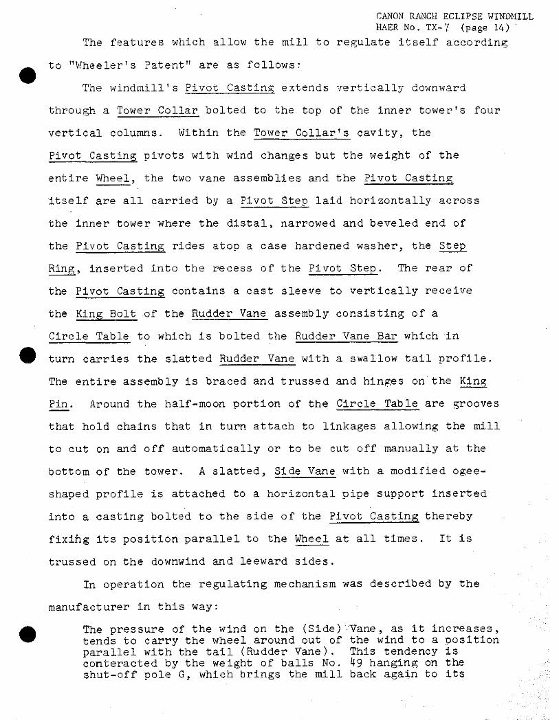
The features which allow the mill to regulate itself according
to "Wheeler1s Patent" are as follows:
The windmill's Pivot Casting extends vertically downward
through a Tower Collar bolted to the top of the inner tower's four
vertical columns. Within the Tower Collar's cavity, the
Pivot Casting pivots with wind changes but the weight of the
entire Wheel, the two vane assemblies and the Pivot Casting
itself are all carried by a Pivot Step laid horizontally across
the inner tower where the distal, narrowed and beveled end of
the Pivot Casting rides atop a case hardened washer, the Step
Ring, inserted into the recess of the Pivot Step. The rear of
the Pivot Casting contains a cast sleeve to vertically receive
the King Bolt of the Rudder Vane assembly consisting of a
Circle Table to which is bolted the Rudder Vane Bar which in
turn carries the slatted Rudder Vane with a swallow tail profile.
The entire assembly is braced and trussed and hinges on'the King
Pin. Around the half-moon portion of the Circle Table are grooves
that hold chains that in turn attach to linkages allowing the mill
to cut on and off automatically or to be cut off manually at the
bottom of the tower. A slatted, Side Vane with a modified ogee-
shaped profile is attached to a horizontal pipe support inserted
into a casting bolted to the side of the Pivot Casting thereby
fixing its position parallel to the Wheel at all times. It is
trussed on the downwind and leeward sides.
In operation the regulating mechanism was described by the
manufacturer in this way:
The pressure of the wind on the (Side) /Vane, as it increases, tends to carry the wheel around out of the wind to a position parallel with the tail (Rudder Vane). This tendency is conteracted by the weight of balls No. 49 hanging on the shut-off pole G, which brings the mill back again to its

CANON RANCH ECLIPSE WINDMILL HAER No. TX-^f (page 15)
normal position as the wind'dies away, thus enabling the mill to take care of itself with a surety in all kinds of weather.
(Fairbanks, Morse & Co., 1910: 6).
The manual cut-off mechanism called the Out Gear Heel is
distinctive in the "Railroad Eclipes" types and is present on
the Canon mill. In appearance it resembles a ship's capstan and
was a major departure from almost all other windmill manufacturers,
who mostly used a simple hinged lever to manually cut off the
wheel. The force of wind on such large mills coupled with the
longer length of travel for its long rudder vane to be brought
parallel to the wheel was solved by this Out Gear Reel attached
vertically to the side of the tower near the ground. By turning
the arms a chain was wound onto the reel that was stopped from
unwinding by a Pawl acting on corresponding teeth in a ratchet
fashion. The chain in turn is connected to a heavy gauge wire
ascending the inside tower where it returns over a Reel Sheave,
descending to its attachment to the bottom of the Cut-Off Pole.
When the chain and attached wire is reeled, it causes the Cut-Off
Pole, overruling its attached Regulating Ball Weights, to push
a slide mechanism composed of rods, guides, and supports that apply
tension to the Circle Board Chains and brings the Rudder Vane in
toward the Wheel. In such a position, as in the automatic regu-
lation, the Rudder Vane guides the wheel out of the wind which
ceases to turn the Wheel. When the Pawl is released and the Out
Gear Reel unwound, the Regulating Ball Weights act as in the
automatic regulating system which turns the Rudder Vane to its
original working position perpendicular to the Whee1.
D. Site:
1. General setting and orientation:
CANON RANCH ECLIPSE WINDMILL HAER No. XX-.7 (page 16)
The windmill is located at the western edge of the ranch
headquarters complex. Upon entering the gate to the complex, the
owner's house is to the right. The road leads straight ahead
to the ranch manager's house, and turns to the left toward a
helper's house and continues west to the nearby windmill, barns,
and corrals.
PART III. SOURCES OF INFORMATION
A. Early Views:
Photographs from Canon Family members:
Catalog C-4-B (CCO-30-W-1; C-4-C(CCC)-31-W-2; C-4-D(LRC)-W-3;
C-4-E(LRC)-W-4; C-4-F(LRC)-W-5; C-4-G(LRC)-W-6; C-4-H(LRC)-W-7;
C-4-J(LRC)-W-8; C-4-K(LRC)-W-9; C-4-L(LRC)-W-10; C-4-M(LRC)-W-ll;
C-4-N(LRC)-w"-12; C-4-0(LRC)-W-13; C-4-P(ALRC)-W-14; C-4-A(GCB)-
ll-W-15; C-4-Q(LRC)-W-l6; C-4-R(LRC)-W-17; C-4-S(LRC)-W-l8;
C-4-K(GCB)-5.
(Cataloged copies in collection of G. M. Canon).
B. Interviews:
George M. Canon of Denver, Colorado, 1981.
Dr. T. Lindsay Baker, Canyon, Texas, 1981.
C. Bibliography:
1. Primary and Unpublished Sources:
Beloit Historical Society. (Untitled) regarding history of the Eclipse Companies (undated). Copy in collection of G. M. Canon.
Canon, George M. Field journal, 1981. Collection of Q. M. Canon.
Reynolds, Blanche Canon. Taped reminiscenses of Canon Ranch Life, 1974 (copy in collection of G. M. Canon.)
Wolfe, Billie. Rancher regarding Eclipse windmill. Transcript from tape recording by Charles C. Canon, San Angelo, Texas, 1965- (Copy in collection of G. M, Canon.)
2. Secondary and Published Sources:
CAKON RANCH ECLIPSE WINDMILL HAER No. TX-7 (pageH7)
Baker , T. Lindsay. "Turbine-Type Windmills of the Great Plains and Midwest." Agricultural History3 L3, No. 1 (January 1980), pp. 38-51.
A Field Guide to American Windmills. Norman, OK: University of Oklahoma Press, in press.
Eclipse Windmill Co. "Descriptive Catalog," 12th ed. Chicago, IL: H. C. Tiffany & Co., 1879. (Library of Congress)
Fairbanks, Morse & Co., Inc. "Instruction No. 2056 Eclipse Windmill 'Railroad' and 'Texas Pattern,'" 1908. (private collection).
Fairbanks, Morse & Co., Inc. "Instruction No. 2056 Eclipse Windmill 'Railroad' and 'Texas Pattern,'" 2nd ed., July 1910.
Fairbanks, Morse & Co., Inc. "Instruction No. 2056 Eclipse Windmill 'Railroad' and 'Texas Pattern,'" 1914, (Fairbanks Morse Engine Division, Colt Industries, Beloit Wisconsin).
Web, Walter, Prescott. - The Great Plains. Ginn & Co., 1931.
Newspaper Articles on or mention of Canon Ranch "Eclipse"
Anonymous
"Library Shows Photographs of Noted Windmill Collections," The University Daily, Lubbock, Texas, January 11, 1967, p. 2.
"Old Eclipse Mill." San Angelo Standard Times, May 12, 1963.
"On Stewart Ranch, Ancient Windmill Preserved." Devils River News, Sonora, Texas, 2 July, 1980, pp. 1,8.
Burton, Gerry. "Passing Era Lives Again in Pictures." Lubbock Avalanche-Journal, July 18, 1968.
Canon, George M. "Ancient Mill on Canon Ranch Turns Eagerly to Every Wind," West Texas Livestock Weekly. San Angelo, Texas. November 15, 1973, pp.. 10-11.
Tolbert, Frank X. "Story of a Great Windmill Fixer." Dallas Morning News, April 33 1967? p. 10.
Woodward, Mrs. Burch. "Windmills—Are They Really 'Desert Air Conditioning'?" The Fort Stockton Pioneer. Fort Stockton, Texas. October 13, 1973, PP- 1 and 7.
CANON RANCH ECLIPSE WINDMIL HAER No. TX-T (page 13)
PROJECT INFORMATION:
Prepared by : James E. White, AIA Project Supervisor
August, 1981
The documentation of the Canon Ranch Eclipse Windmill, in the vicinity of
Sheffield, Pecos County, Texas was undertaken by White Associates, AIA,
Architects, Lubbock, Texas, in cooperation with Texas Archaeological Foundation,
Inc., George M. Canon, and the Historic American Buildings Survey (HABS) of
the National Park Service's National Architectural Engineering Record, South-
west Regional Office, The project was completed in the summer of 1981 in the
HABS Field Office of White Associates, by James E. White, AIA, Project Super-
visor (Associate Professor of Architecture, Texas Tech University); Tony
Ape! (Texas Tech University), and Scott Sanders (Texas Tech University).
CANON RANCH ECLIPSE WINDMILL HAER No. TX-T (page 19)
APPENDIX A
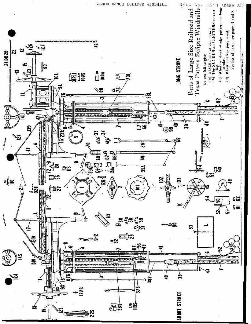
Parts■List References to Drawings
CANON RANCH ECLIPSE WINDMILL HAER No. TX-T (page 20)
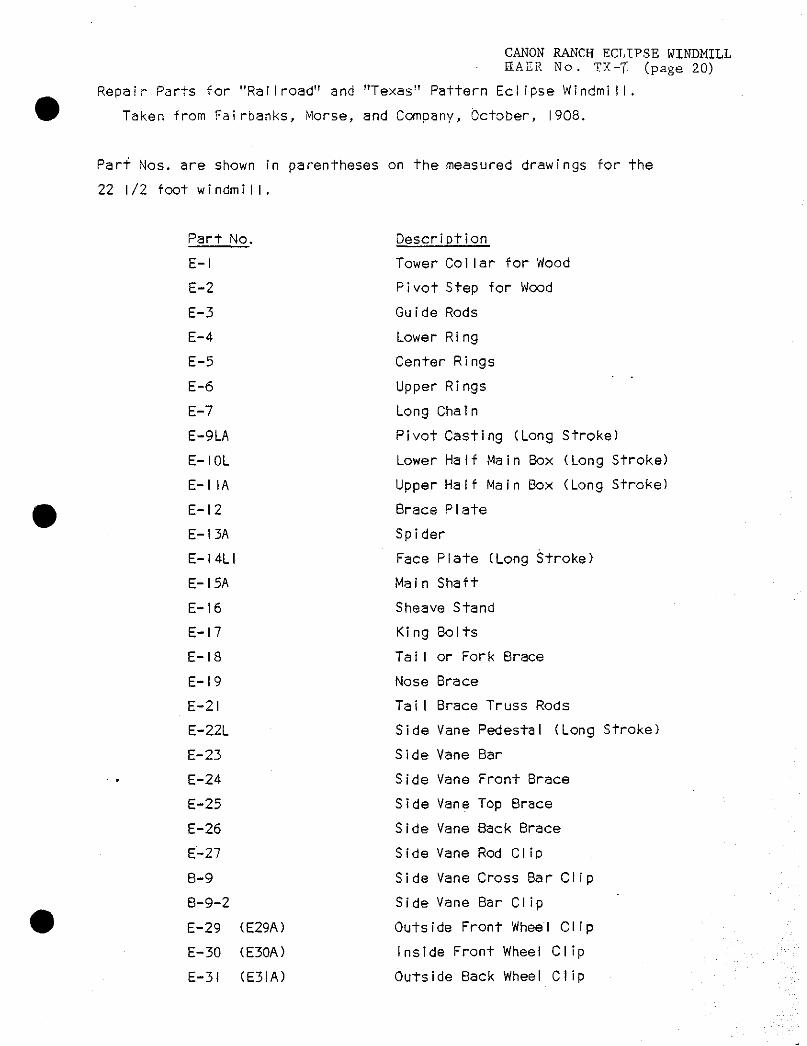
Repair Parts for "Railroad" and "Texas" Pattern Eclipse Windmill.
Taken from Fairbanks, Morse, and Company, October, 1908.
Part Nos. are shown in parentheses on the measured drawings for the
22 1/2 foot windmiI!.
Part No. Description
E-l Tower Cot lar for Wood
E-2 Pivot Step for Wood
E-3 Guide Rods
E-4 Lower Ring
E-5 Center Rings
E-6 Upper Rings
E-7 Long Chain
E-9LA Pivot Casting (Long Stroke)
E-IOL Lower Half Main Box (Long Stroke)
E-l1A Upper Half Main Box (Long Stroke)
E-l2 Brace Plate
E-I3A Spider
E-I4LI Face Plate (Long Stroke)
E-I5A Main Shaft
E-l6 Sheave Stand
E-l7 King Bolts
E-l8 Tat I or Fork Brace
E-l9 Nose Brace
E-2I Tai I Brace Truss Rods
E-22L Side Vane Pedestal (Long Stroke)
E-23 Side Vane Bar
E-24 Side Vane Front Brace
E-25 Side Vane Top Brace
E-26 Side Vane Back Brace
£-27 Side Vane Rod Clip
B-9 Side Vane Cross 8ar Clip
B-9-2 Side Vane Bar Clip
E-29 (E29A) Outside Front Wheel Clip
E-30 (E30A) Inside Front Wheel Clip
E-31 (E3IA) Outside Back Wheel Clip
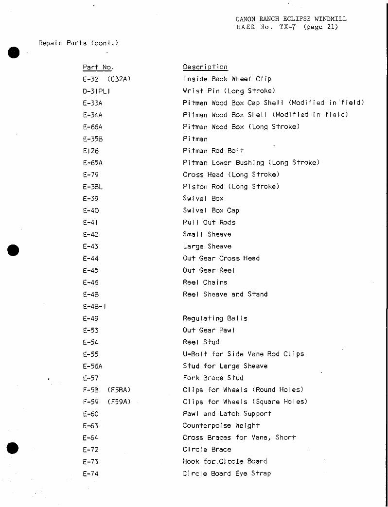
Repair Parts (cont.)
CANON RANCH ECLIPSE WINDMILL HAER No. TX-T"; (page 21)
Part No,
E-32 (E32A)
D-3IPLI
E-33A
E-34A
E-66A
E-35B
EI26
E-65A
E-79
E-38L
E-39
E-40
E-41
E-42
E-43
E-44
E-45
E-46
E-48
E-48- I
E-49
E-53
E-54
E-55
E-56A
E-57
F-58
F-59
E-60
E-63
E-64
E-72
E-73
E-74
(F58A)
CF59A)
Descri ption
Inside Back Wheel Clip
Wrist Pin (Long Stroke)
Pitman Wood Box Cap She!! (Mod if ied infield)
Pitman Wood Box Shell (Modified in field)
Pitman Wood Box (Long Stroke)
Pitman
Pitman Rod Bolt
Pitman Lower Bushing (Long Stroke)
Cross Head (Long Stroke)
Piston Rod (Long Stroke)
Swivel Box
Swivel Box Cap
Pu!1 Out Rods
SmalI Sheave
Large Sheave
Out Gear Cross Head
Out Gear Reel
Reel Chains
Reel Sheave and Stand
Regulating Bat Is
Out Gear Pawl
Reei Stud
U-Bolt for Side Vane Rod Clips
Stud for Large Sheave
Fork Brace Stud
Clips for Wheels (Round Holes)
Clips for Wheels (Square Holes)
Pawl and Latch Support
Counterpoise Weight
Cross Braces for Vane, Short
Ci rcfe Brace
Hook focXiccie Board
Circle Board Eye Strap
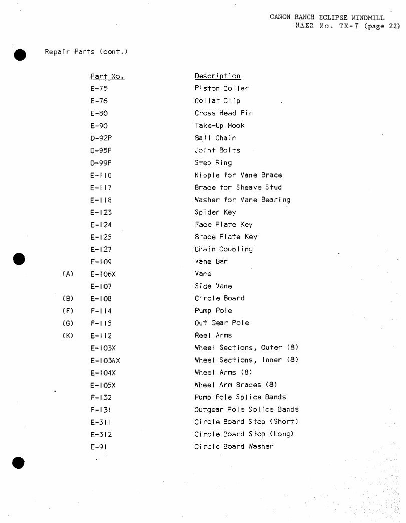
Repair Parts Ccont.)
CANON RANCH ECLIPSE WINDMILL HAER No. TX-T (page 22)
(A)
(B)
(F)
(G)
CK)
Part No,
E-75
E-76
E-80
E-90
D-92P
D-95P
D-99P
E-IIO
E-II7
E-l 18
E-123
E-l 24
E-l 25
E-l 27
E-l 09
E-106X
E-l 07
E-108
F-l 14
F-l 15
E-l 12
E-I03X
E-103AX
E-I04X
E-I05X
F-l 32
F-I3I
E-31 !
E-312
E-91
Description
Piston Coliar
Col Iar Clip
Cross Head Pi n
Take-Up Hook
Bat I Chain
Joi nt Bolts
Step Ring
Nipple for Vane Brace
Brace for Sheave Stud
Washer for Vane Bearing
Spider Key
Face Plate Key
Brace Plate Key
Chain Coup IIng
Vane Bar
Vane
Side Vane
Circle Board
Pump Pole
Out Gear Pole
Reel Arms
Wheel Sections, Outer (8)
Wheel Sections, Inner (8)
Wheel Arms (8)
Wheel Arm Braces (8)
Pump Pole Splice Bands
Outgear Pole Splice Bands
Circle Board Stop (Short)
Circle Board Stop (Long)
Circle Board Washer
CANON RANCH ECLIPSE WINDMILL HAER No. TX-T (page 23)
APPENDIX B
Bolt3 Screw, Nail and Chain Sizes
CANON RANCH ECLIPSE WINDMILL HAEE No. TX-T
(page 24)
BOLT, SCREW, MAIL, AND CHAIN SIZES
Positions and sizes by inference or from artifacts, except where:
* Confirmed by Parts List B.F. 144 500 dated 10/17/06.
** Departure from Parts List for additional length due to later
factory style of some reinforced wheel clips, or due to more
thread needs for double-nutting on Canon mill rather than
following Instructions 2056 (10-80) where bending bolt end over
was recommended for preventing loosening of nuts.
WHEEL ASSEMBLY
1. WHEEL CLIPS
Representative ARM of eight, from outer to inner positions
backed by washer on nut side.
a) W.C. E29A and E31 A assembled:
** One 5/16" x 3 1/2" carriage bolt through ARM, inner hoL
* One 5/16" x 3 1/2" (** or 4" length) carriage bolt
through ARM, outer hole.
** Two 5/l6" x 6" carriage bolts on castings' flanks.
b) W.C. F29A and F59 (or 59) assembled:
* Three 5/16" x 5 1/2" carriage bolts (Except F58A
and 58 are for round holes requiring square headed
bolts).
c) Next position, bolts identical to (b).
d) W.C. E32A and E30A (Or 30E) assembled:
* One 5/16" x 5 1/2" carriage bolt
2. GIRT or WHEEL ARM STUD, between BRACE AND ARM, each of eight:
One 3/8" x 18 1/4" square headed bolt.
CANON RANCH ECLIPSE WINDMILL HAER Mo. TX-r
(page 25) 3. COUNTERPOISE WEIGHTS, two assembled opposing (Canon Mill):-
Two 1/2" x 6" carriage bolts.
Factory: Single or in tandem, each weight:
* Two 3/8" x 3 1/2" bolts.
4. SPIDER, for one flange of eight, each positioning an ARM.
Two 1/2" x 4 1/2" carriage bolts.
5. BRACE, for one of eight, all carriage bolts:
One 5/16" x 3 1/2" and one 5/16" x 4 1/2", outer edges.
Two 3/8" x 2 1/2" for BRACE PLATE position.
6. BLADES OR SLATS, from outer to inner WHEEL SLAT SUPPORTS of
four in typical wheel section, one nail into each SLAT and
SUPPORT:
12d casing; 8d casing; 8d-casing; 6d finish.
RUDDER (HINGED) VANE ASSEMBLY
Orientation is viewer looking from WHEEL center to RUDDER VANE in
operation. Depth orientation is from CIRCLE BOARD edge toward
RUDDER VANE's distal end.
1. CIRCLE BOARD.
CIRCLE BOARD STOPS, top entry through washers:
Eight 5/16" x 3" carriage bolts.
NOSE BRACE:
One 3/4" head x 3" lag bolt, top hole.
One 1/2" head x 4" lag bolt, bottom hole.
CIRCLE BOARD EYE STRAP and CIRCLE BOARD HOOK STRAP:
Two #14 screws securing each of the STRAPS.
CIRCLE BOARD WASHER:
Three #14 screws.
2. RUDDER (HINGED) VANE BAR AND RUBBER (HINGED) VANE.

CANON RANCH ECLIPSE WINDMILL HAER No. TX-T
(page 26)
"VANE BAR BRACE" and through RUDDER VANE BAR, left entry with
left and right washers:
Holes 1,2,3) and 4:
3/8" x 10" carriage bolts.
Hole 5:
1/2" x 10 1/2" carriage bolt securing CIRCLE BRACE left
and welded truss of right CIRCLE BOARD STOP through
"OAK BRACES" and RUDDER VANE BAR. Left entry with
right washer.
Carriage bolts securing vertical girts of RUDDER VANE, to
RUDDER VANE BAR, left entry with left and right washers:
Hole 6, 7:
3/8" x 6".
Hole 8:
3/8" x 5".
Hole 9, 10:
* 3/8" x 5 1/2" and * 5/8" x 6 1/2" (Square Bolts), TAIL
BRACE TRUSS RODS and PORK BRACE to RUDDER VANE sheet,
left entry, left and right washers.
Hole 11, 12:
3/8" x 4 1/2".
Hole 13:
3/8" x 7 3/4", that also secures center hole of CROSS
BRACES of VANE, and wood NIPPLE FOR VANE BRACE.
Hole 14:
3/8" x 7 3/4".

CANON RANCH ECLIPSE WINDMILL HALR No . XX-7- (page 27)
SIDE VANE ASSEMBLY
SIDE VANE PEDESTAL, to PIVOT CASTING:
Two 5/8" x 4" hex headed boits.
SIDE VANE CROSS BAR:
One 7/16" "U" bolt for CLIPS.
Two 5/16" x 1 3/4" square bolts, distal end on Canon
Mill, not factory.
MISCELLANEOUS
1. OUT GEAR CROSS HEAD, in attachment to OUT GEAR POLE:
Two 3/8" x 3", square headed bolts, and washers.
2. OUT GEAR POLE:
One 3/8" x 3" eye bolt for cut-off chain.
One'3/8" x 3" eye bolt for REGULATING BALL WEIGHTS.
3- REEL SHEAVE:
* Two 3/8" x 3 1/2" lag screws.
4. PAWL:
One 3/8" x 10" square bolt, Canon Mill arrangement.
*" One 3/8" x 4 3/4", for factory arrangement.
5. WOOD REEL ARMS
Six 5/16" x 2 1/2" carriage bolts.
6. SWIVEL BOX and CAP:
Two 3/8" x 2 3/8" square bolts.
7. SWIVEL BOX securing OUT GEAR or PUMP POLE:
Three 3/8" x 5" carriage bolts.
8. OUTGEAR (or PUMP POLE) SPLICE BANDS for attachment to surface
pump rods:
Pour 3/8" x 4 1/2" square bolts.
9. UPPER HALF MAIN BOX, to LOWER HALF MAIN BOX:
Sight 5/8" x 1 3/4", square bolts.
CANON RANCH ECLIPSE WINDMILL
HAER No. TX-7
(page 28)
10. LOWER HALF MAIM BOX, to PIVOT CASTING;
Sight 5/8l! x 2", square bolts.
11. TOWER COLLAR:
* Four 1/2" x 6", joint bolts.:
12. PIVOT STEP:
* Two 1/2" x 5 1/2" square bolts with top washers.
13. LONG and SHORT CHAINS, from pierced lug on E5 CENTER RING
to CIRCLE BOARD STRAPS:
Link size: 1/4" thick, 1 9/16" x 1 1/16"
SHORT CHAIN,
LONG CHAIN,
CANON RANCH ECLIPSE WINDMILL HAER No. TX-T (page 29)
APPENDIX C
Paint Colors

CANON RANCH ECLIPSE WINDMILL HAER No. TX-T (page 30)
PAINT SCHEDULE
ECLIPSE GREEN
Sherwin Williams Formula:
SWP Base B (oil base)
Veldt Grass
3 oz. Gold
4/32 Maroon
8/32 Black
RED TRIM
Sherwin Williams Standard Color Oil Base Paint
TARTER RED . .
BLACK METAL PARTS
Outside Implement Black (gloss)

CANON RANCH ECLIPSE WINDMILL HAER No. TX-7 (page 31)
•
APPENDIX D
Fairbanks Morse Instructions No. 2056
1908

CANON RANCH ECLIPSE WINDMILL HAZR No. XX-T (page 32; 1M Otiober, 1908 I
INSTRUCTIONS NO. 2056 (Used in Connection with BF46)
ECLIPSE WINDMILL cc Railroad" and "Texas" Pattern
DIRECTIONS FOR ERECTING ON WOOD OR ' STEEL TOWERS AND REPAIR PARTS LIST
>*
Fit. .w«o2
FAIRBANKS, MORSE (iNcoiroaATzo)
Address Our Nearest Warehouses
& CO
duof* in. New York. S. Y- ^^▼w Loodoo, England Sao JruaxKO. CaL Cinciuiuti, Oluo St Loni* Mo. St. Paul, Hinn. Lot.Aagele*. CaL ClereJand, Ohio Indiana polk, Ind. Salt Like Citr, Utah Bak«n&&.Gd. LwicrvOle, Kr- Kioto* City. Mo. PJ ̂
SpoluAf, 'Wath. Santa liana, Ci). Detroit, Mich. Omaha. Jwb. Seattlt, Wash. Portland. Orepn
. Miaaeupotb. Mina. Denver, Colo. ••*ss«
Copjtf *kt 19°* *>r M*b«ki, Mon« & Co.
L.A1NUJN KAWL.H HULlfbti WJUNDM11.L.
FAIRBANKS, MORSE dfr CO.
■i (,page JJJ
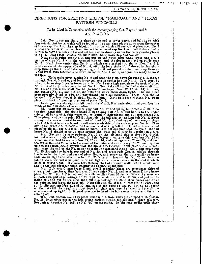
DIRECTIONS FOR ERECTING ECLIPSE "RAILROAD" AND PATTERN WINDMILLS
'TEXAS"
To be Used in Connection with the Accompanying Cut, Pages 4 and 5
Also Print BF46
1st. Put tower cap No. 1 in place on top end of tower posts, and bolt down with four J-inch joint bolts, which will be found in the box; then plumb down from the center of tower cap No. 1 to the step block of tower on which mill rests, and place step No. 2 so that the center will come plumb under the center of cap No. X and bolt it down, being careful to "hare the holes in the ends of No. 2 come directly under the corresponding holes in No. 1. Place steel washer No. 99 in step, oiling both step and washer.
Next put in guide rods No. 3, and put on the nuts; then place lower ring No. 4 on top of step No. 2 with the recessed aide up, and the slot in each end on-guide rods No. 3. Next place center ring No. 5, to which are attached two chains, Nos. 7 and S, in the recess of the upper side of No. 4, with the long chain No. 7 down, letting chain drop through No. 4; then take upper ring to No. 6 and pass short chain No. 8 up through it and lay it with recessed side down on top of Nos. 4 and 5, and you are ready to hoist the mill.
2d. Hoist main pivot casting No. 9 and drop the stem down through No. 1, thence through N03. 4, 5 and 6, and let Tower end rest in socket in step No. 2. Care must be taken to have step block in tower on which No. 2 rests high enough so the neck of pivot No. 9 will show } inch above top of No. 1. Next take off top half of main shaft box No. 11, and put main shaft No. 15 (to which are keyed Nos. 12, 13 and 14) in place, and replace No. 11, and put on the nuts and screw them down tight. The shaft has been properly fitted to box, and pasteboard liners are furnished. Those liners should be used. The box should fit tight, but not bind. Next bolt sheave stand No. 16 in place just back of opening in center of pivot No. 9.
In designating the right or left hand side of mill, it is understood that you face the wind, as the mill does when in motion. * ..
3d. Take nut off lower end of king bolt No. 17 and spring tail brace NV.18.off.on the right-hand side; slip circle board B on to king bolt No. 17 and bolt it to the under side of tail bar A. with bolts which will be found in their places, and put stop braces No. 72 in place.as shown in print BF46; then hoist the tail and let the king bolt !No. 17 down through the hole or socket in rear end of pivot No. 9, so that one of the wrought stops which is bolted to circle board B will come each side of the cast stop on No. 9. Then spring tail brace No. 18 back on to the lower end of king bolt No. 17, put on the-nut and screw up till tail bar A is level, and no more. It is not designed that the eye of the tail brace No. 18 should come up snug against the lower end of king bolt socket in No. 9.
4th. Fasten side vane pedestal No. 22 on the left-hand side of pivot No. 9 with four set screws, which will be found in their places; then take side vane bar No, 23 to which are attached brace rods Nos. 24, 25 and 20, and castings Nos. 27 and 2S, and bolt the fan of the side vane on to the cross at the outer end and casting No. 28. and tighten up the set screw, being careful that the fan is not twisted. Next raise the side vane and insert the end of bar No. 23 in the socket on left-hand side of No, 9, put brace rod No. 25 through tho hole in top end of No. 22, and brace rods Nos. 24 and "26 through the holes in the front and rear of pivot No. 9, and screw up the nuts until the brace rods are all tight and sido vane bar No. 23 is level; then set bar No. 23 so that the fan on the outerend is perpendicular and tighten up the set screw in the socket which holds_ it pretty tight. It is now best to bring the tail around parallel with the side vane and tie the two together while erecting the balance of the mill
5th. Bolt arm 0, arm brace D and girt E together (these are sometimes shipped already put together); then bolt arm C into spider No. 13. and arm brace D into brace plate Mo. 12. (Girt E is not used in mills smaller than 20 feet.) When the arms are all bolted in, put clip castings No. 29 in place, as shown in Print BF46, and put in the inside bolt and put on the nut; then put clip castings No. 30 in their places and drive the bolts in, but leave the nuts off. Next slip sections of fan in from rear of wheel and put in clip castings Nos. 31 and 32, and put in the bolts as you go, but do not screw up the nuts till the wheel is all put together, then care must be taken to have all the nuts screwed up tight. It is good practice to head the bolts over to prevent the nuts coming off. •
8th. Put pitman No. 35 in place, remove nut from wrist pin shipped with pitman No. 35, drive wrist pin in the hole giving desired stroke, replace nut, tighten securely. Next place knuckle No. 38S, or No. 79L, on its guide. In the long stroke mills these

CANON RANCH ECLIPSE WINDMILL " KAER NcM TX-T (page 34)
FAIRBANKS, MORSE & CO-
are planed ways on the legs inside the pivot No. 9. In the short stroke mill, swing the knuckle No. 303 out to the right-hand side of the mill, and slip guide bar No. 37 through the box on one aide of it, and place guide bar in the slotted lugs on the stem of pivot No. 9; be sure the bar is crowded back snug to the bottom of slots and screw up the nuts tight. Replace the caps over 3lots. The end of guide bar No. 37 which has two nuts on goes up, ■with one nut above and one below the upper lug; then take the nut off the upper end of piston No. 38 and pass it up through the hole in lower end of pivot No. 9, replace the nut and screw it into knuckle No. 36S and then set "the nut up solid against the bottom of knuckle No. 36S; this can be best done with a hammer and cold chisel. It is deemed. best by some to put pitman No. 35, knuckle No. 365, and guide bar No. 37 in their position on the ground and hoist them with pivot No. 9 ,aa
efore described. In this case it will be best to put in piston No. 38 temporarily,- to see that it works freely—which it will do if guide bar is snug back in bottom of slot— and take it out again before hoisting- No. 9. Next splice pump pole F and fit swivel box No. 39 on the upper end, then take cap No, 40 off swivel box No. 39 and bolt it on to the neck on lower end of piston No. 38 and then bolt pump; pole F in swivel box No. 39. Next get length of pump pole F, which is done by placing the pump and mill both on.the center of stroke, and cut it off and bolt it to the pump.
The counterweight No. 63 should be bolted to the "wheel arm opposite crank pin. This counterbalances weight of the pump pole, and should be adjusted according to the depth of the well. The deeper the well, and the more pump pole used, the farther out this casting should be placed.
7th. Raise rings Nos. 4, 5 and 6 up on to stem of pivot No. 9, and enter the lugs on ring No. 5, between the sides of pivot stem; then put in pole rods No. 41, the end with single nut on going up; take on the nut and pass the rods up through the inside holes in the end of step No. 2; replace the nuts and screw them well down, then pass the rods up through corresponding holes in ring No. 4, and screw them into ring No, 6 till you get a full thread and then set the nuts up tight under ring No. 4, so as to hold rings Nos. 4 and 6 firmly together, as shown in Print BF46. Next place small sheaves No. 42 in sheave stand No. 16; raise rings Nos, 4, 5 and 6 upon stem of pivot No. 9 close to tower cap No. 1; then pass short chain No. 7 up through pivot No. 9 and over the right sheave into a hook which is fastened on to circle board at that point. Next place large sheave No. 43 on the stud shipped attached to the lower end of pivot- stem No. 9; place sheave so the oil hole will be on the outside. Replace stud braces, then pass along chain No. 8 down around sheave No. 43, thence up through rings Nos. 4, 5 and 6 and through pivot No. 9; thence over left-hand sheave No. 42 and around circle board B to left corner, where it is attached by means of a hook with a long thread passing through a plate which is screwed to circle board B at that point; the design of this hook is to take up the slack of the chain, as it may wear from use, and when put up new should go through the plate just far enough for a full nut. If chain No. 8 should bs too long, cut otl one or more links to make it right;- then put shut-off cross head No. 44 on lower end of pull rods No, 41 with nut above and below it, as shown in Print BF46, and screw up tight. Care must be taken to have all the nuts of pull rods No. 41 screwed up very tight, as there is danger of their working loose if tb*y are not. Next splice shut-off pole G and bolt it to cross head No. 44, leaving it long enough to run down through the platform of well or pump pit; when it is raised up and mill is clear out of the wiud, this will serve as a guide to the pole at that point.
8th. Proceed to erect shut-off arrangement as shown in Print BF46. Standards J (not furnished with mill or tower) are 3x6, 8 feet long, the lower end of which rests on the platform of well, and the upper end secured to a plank fastened across the tower. The center of reel No. 45 should be six feet above platform; bolt wood arms K into reel No, 45 and put in place, and put on the ratchet; then spike a 2x8 plank across standards J and fasten sheave No. 4S to it with lag screws which are in the box. Place the sheave about the center of reel No. 45 (this piece 2x8, to which sheave No. 48'is fastened, is not shown in cut), pass long reel chain No. 47 (which is aiwavs fastened to the end of the reel to which the arms are attached) over sheave No. 4S; thence down through platform and attach to hook on top of water box L, The location of water box L can be governed by rod of greater or less length between the hook on box and chain No. 48, as it is some- times necessary to vary it on account of timbers in the well. Next place weight box No. 50 on shut-off pole G, as shown in Print BF46, so that the bottom of it will,be about
• two. inches above platform; then let the mill into the wind so that the shut-off pole G will bo clear down and bolt the two smallcast lugs, which will be found in the box, on to pole close down on top of weight box No. 50; then bring short reel chain No. 46 down and pass the eye bolt, which is on the end of it, through the hole ia4ug on the inside
UANON KAJNCti ELLIPSE WINDMILL

CANON RANCH ECLIPSE WINDMILL IIA: No TX-7 (page 36 FAIRBANKS, MORSE & CO.
of weight box No. 50 and put on the nut. The chain should be adjusted on reel No. 45 so that, when weight box No. 50 is clear down, the water box h will be at the highest point deaired. Guide the poles F and G at points about 10 to 12 feet apart up through the tower.
This arrangement for an automatic shut-off is operated by means of an overflow pipe running from the top of tank*and discharging the overflow into water box L, the weight of which, when full, turns reel No. 45 and throws the mill out of the wind. This water, after the overflow from tank ceases, wastes out of water box L through a small hole in the bottom, and lets the mill,back into the wind again. When this arrange- ment is used, the ratchet should be thrown back so as to let the reel play- unobstructed, except when it is desired to keep the mill out of the wind for any purpose. If the auto- matic shut-off is not used, leave off water box L, long chain No. 47, sheave No. 4S and weight box No. 50, putting the eye bolt on short chain No. 46 through the pole G, instead of attaching to weight box No. 50. The design of weight box No. 50 is to balance water box L, and as water box L gets soaked and grows heavier it will be necessary to put sand or some heavy material into weight box No. 50 to counterbalance it.
9th. Place ball box H at some convenient point in the upper part of the tower close to shut-off pole G; then throw the mill clear out of the wind and hang string of balls No. 49 on to shut-off pole G, so that the weight of all the balls will be on the pole, and the lower ball will clear the bottom of box a about two inches.
The self-regulation of the mill is here seen, viz.: The pressure of the wind on the vane, as it increases,- .tends to carry the wheel around out of the wind to a position parallel with the tail* This tendency is counteracted by the weight of balls No. 49 hanging on the shut-off pole G, which brings the mill back again to its normal position as the wind dies away, thus enabling the mill to take care of itself with a surety in all kinds of weather.
.<"<•
IMPORTANT
We must have the following in- formation to correctly fill orders for Windmill repairs;
(1) Diameter or size of Wind- mill.
(2) The symbol letter (or let- ters) preceding the number.
(3) The number on casting, and (4) Approximately the date the
mill was purchased. Just FOUR points. If you
omit any one of them, we rooy be obliged to delay the order and write for further information.
Jl*> TT6603 Working Parts of 20-foot Texas Pattern Eclipse Windmill

FAIRBANKS, MORSE <k CO.
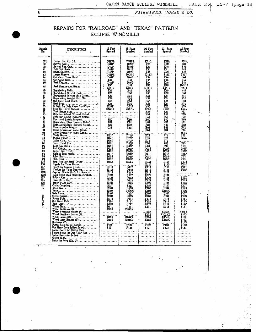
'REPAIRS FOR "RAILROAD" AND "TEXAS" PATTERN ECUPSE WINDMILLS
Repair No.
DESCRIPTION Ift-Foot Symbol
13-Foot Symbol
20-Foot Symbol
22i-Foot Symbol
2J.F(»>t 3>mbol
t DIP D101P
D2P D1G2P D3P D4P D3P D6I' D7P DSP D9P
WPLB
' DIP D101P
IMP D102P
D3P D4P DSP DSP D7P DSP
D9PX D8PLB
El WEI
E2 WE2 E3 E4 E3 Efl E7
. £S E9
E9LA
£1 ■ WEI
E2 WE2 E3 E4 E3 E6 E7 ES E9
E9LA
Fl 101 F101
2 . F2 102 . F102
3 F3 4 F4 3 F3 S FO r F7 S FS
. w 9L 9L F9 0L ^ F9-1
. 10S I-OMf Half Maia Box <L. Sta>kcl Upper Half Main Bos fS. Struke) Upper Half Msia Box (L. Stroke)....
- D10P OIOPL DUP BllPt 012P D13P DI4P
D14PL1 D13P D10P D17P DISP D18P
D10P D10PL D11P
D11PL' D12P D13P DHP
DHPL1 D15P D16P D17P DISP D19P
E10 E10L Ell Ell E12 E13 E14
E14U Eld E16 E17 E1S
E]6A E10L E11A E11A E12
E13A E14
E14L1 EISA E16
• E17 US
10L 11
F10
11 12
m E12
13 Spider. F13 143 14U 14 F13 1C F16 17 F17 18 t P IS
D19 F.19 E!9
£31 £22
E22L E23 KM E25 BO E27 B9
B9-2 E29 E30 E31 E32
D31PI.I
EJ9 .
E21 E22
£22L E23 E24 E» E26 ES7 B9
BO-2 E2a E30 £31 £32
D31PL1
D20 D20P 1)21 P D22P
D23PL -D23P
D24P D25P D20P D27P
D20P D21P D22P
D22PL D23X D24X D25X D36X D27P
A9
21 ' 22$ Side Vane Trfestat (3. Stroke)
Side Vane Pedwcal (L. oun«>
F31
22L 23 24 25
F22 F23 F24
26 27
Side Vane Back Brace. F2fi' E27
2S 9-2
BO
20 6»p D30P D31P D32P
D3IPL1
D39P D30P D31P D32P
D31FL1
E29 30 31 32 31PL1
Outside Bock Wh«i Clip E3T) E31 E32
1I»A !0Q3 Kibb
E33A £34A zmx E6H8 D35A
DOSPA E12li DOfiP
' DfidPl DH"P
D67P1 DtiSP
D6SP1 nsop Df»Pl D70P
D70PI MSP IMWP D33P D34P D35P D*1P D38P D79P D37P D3SP !
■ i
EIOO E33A E34A E3HA E08B D33A
DtMPA E126 D6SP
Dfi6Pl D67P
D67P1 DfiSP
D6SP1 TH59P rwopi D70P
D70P1 D6SP DMF D33P D34P D35P Dft3P D36P D79P D37P D35P
E33A F-34A EBGA EMB E33B FA5B E1M DWP
DtiiiPl D67P -
Dfi7Pl ECS
EfiSA DWP
Dffl>Pl D:OP
D70PI E8SA E6.U D33P D34P Effl
E65A E36 £79 E37 E38
EIOO E33A E34A ElMA Efi6B EMB E6SB E12S DWP
D6fiPl DfiTP
D67P1 EfiS F6SA D09P
DfiftPl D70P
P70P1 EH5A EflSA D33P D34P E33 E«.\ E3n E79 E37 E3S
33A 34A
Pitinu Wood Box Cap Shdl FS3A F34A
« Pitman Wood Bos (L. Strokr) Pitman Wood Box (3. Strob)
F6tiB
35\ W
EM
F35A fMA
68P Pitman B«« Wedge Bos (S.S.)..... Pitman Bras Wedge Bos CL 3.) Pitman Braw Upper Box {3. &>....,.
60P tS7
FtWA
A7 IS '
FS7A
Pitman (I. 3.) F«SA
so TO
Pitmon Strap (L. S.) Pitman W*dw and Bolt fS. SO Pitman ttedm and Bolt (L. S.)
FOA
70 63
F70A
33 F6S F33
U 33
Pitmaa Babbitt Bos. I>*er Ftalf.... F34 F39
A3 3SS
F83
791. F79 37S 38S
CANON RANCH ECLIPSE WINDMILL :;o
FAIRBANKS, MORSE & CO.
■7 (page !38
REPAIRS FOR 'RAILROAD" AND 'TEXAS" PATTERN ECLIPSE WINDMILLS
■Repair No.
DESCRIPTION' 16-Foot Symbol
18-Foot Symbol
20-Foot Symbol
221-Foot Symbol
25-Foot Sj-mlxJ
3SL D3SPL D39P D40P D41P D42P
D43PB D44P E45
IWSP J E4S I E4S-1
E49 £50 £31 £52 £33 E54 D33P
D5GPA
D33PL D39P D4QP &41P D42P
D43PB D44P ■ E45 D46P HIS
E4S-1 E49 E50 ESI £52 £53 £54 DWP
DWFA
E3SL £33 E4Q E41 E12
E43C £44 F« E4« E4S
E4S-1 E49 E» E51 E52 £53 £54 £35 E3SA E57 F3S F59 Etfl E61 ElEJ E«3
_ FW
E72 E75 E7U rso E90 D92P IW3P DWP DMP D9if? £154 El 10 £117 EUS £119 El 22 £123 £124 £125 E127 RIM E106 £107 E10S F114 F1I5 £112 E1U
E3SL £39 E40 £41 £42 £43C ' £44 F45 E46 E48
E4S-1 £49 EM £51 E52 E53 £54 £55 E58A E57 IBS F59 E60 "■ EM ' EB2 £03 F04
£72 £75 £70 £80 ESO D92P D93P OT4P D35P D99P E1S* El 10 El 17 KUS El 10 E122 E123 Km E123 EI27 E109
ElOnX E107 E10S F114 FU5 EU2 El 11
F3SA 39 F39 40 F40 41 F41 42 F42 43 F43FJ 41 F44 45 F45
E4<j 43 D43PA
49 K40 30 51 52
Relating U'eieht Bui Cover. EM
53 54 55 58
Reel Stud , -. U Bolt for Side Vane Rod Ciipi
£53 EM VA
F5GA 57 F57 5S Clip* (or Wheel (Round Hoiwl
Clipi for W'h«i (Square Holes) F58
- 59 F39 00 n»
Eol E»2 C33
EfiO £61 £02 C33
ESO SI
63 U
Regulating Stop (Square Hole^) Rejit Li ling Stop (Round Hdea)......
ESI
F64 64
D72P D75P D7UP OS0P
. DWP D92P D93P ■ D94P DWP D99P DMA
¥6 (A 72 D72F
D73P D78P D8QP D9CP D92P D93P D9JP D93P D39P D54A
73 F75A 76 Cailar Clip..; 80 FSO 90 92 93 1)33 P 94 95 Fas 09 F99
103 110
Step Rod for Steel Tower Fl-lt EiiO
117 DUT" D118 £119 Ei22 D123 D124 D123 E127 DI09 Dion Dior D10S D1I4 FU5 F.I 12 Dili Dt03
fiiii DUS E1I9 EI22 D123 D124 D123 E127 Dl09
DUBX D107 DIGS Dili Flli El 12 Dill
D103X
11* FUS ' 1193 Cap for Guide Shalt (3. Strok-s)
Main Shaft Box Stud (S. Stroke) 122$ 123 Ft23 134 F124 125 127 A
F125 E127
Vane. FlOtt F10T
8 nos F G
F114
K L
Wiwl S*eti««w (8) U"he*i Settiom, Outer (8) M'hcd Section*. Innrt (8)... Wheel Ann* <8)
FIB Fill
E103A £103 £104 £105
E103X E103AX
E104X E103X
F103A
bio* D103
D104X DI05X
FI03
F105 F113
FJ32 F131
F132 F131
F132 F131
F132 F131
F132 F131
3piiee Bolt* for Pump Pule Splice Stilts for Out Gear Pule
WhedBuIt*
UAJMUN KAWCH. KULl^bii WINDMILL HALK :id. Tli- ".f (.P^ge J9)
B. F. 144. 500 10-37-06
4 .vV
Beloif, WIs ,. .190.
20-FOOT ECLIPSE WIND MILL.
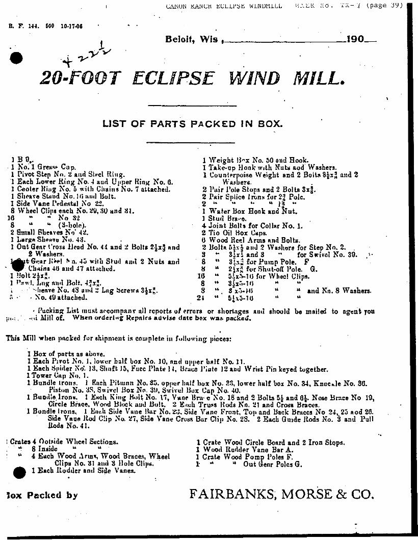
LIST OF PARTS PACKED IN BOX.
1 B 9,. 1 No. 1 GreHsw Cup, 1 Pivot Step No. 2 and Slt-el Ring. 3 Each Lower King No. 4 aud Upper K'xnx No. 0. ] Center King No. 5 with Chains No. 7 attached. 1 Sheave Stand No. Hi ami Bolt. 1 Side Vane Pedestal Xo 22. 8 Wheel Clips each No. 29,30 and 81.
J6 No 32 8 (3-holn). 2 Small Sheaves No' 42. 1 LargrA Shelve No. 43. 1 Out Gear Cross lieod No. 44 and 2 Bolts 2$x§ and
2 Washers. ^utG<*arK«»! N o. 45 with Stud and 2 Nuts and
" ^P -Chains 40 and 47 atUchud. 1 »o!t2ix*. 1 *'**!, Lug and Bolt, 47x3. i "heave No. 48 ami 2 Lag bcrewa 3^xjJ. » ■' • Xo. 49 attached.
i Weight B«x No. 50 and Hook. 1 Take-up Hook with Nuta and Washere. 1 Counterpoise Weight and 2 Bolts 3Jz^ and 2
Washers. 2 Pair Pole Stops and 2 Bolts Sxg. 2 Pair Splice Irons for 22 Pole. n u it ■. u j a «■
1 Water Box Hook and Nut. 1 Stud Bra>*e. 4> Joint Bolls for Collar No. 3. 2 Tin Oil Box Caps. 0 Wood Heel Arms and Bolts. 2 Bolta 61x1 and 2 Washers for Step No. 2. . 3 *• Six! and 3 ** for Swivel No. 39. ,*■ 8 " 8is3 for Pump Pole. F H M 2{x;| for Shut-off Pole. G.
10 " 5ix-V10 for Wheel Clips. 8 " 3jx"i-l« 8 u. 3x5- MS w " and No. 8 Washers.
24 u 5ix5-10 ** w
JM.;
• Packing List must accompanr alJ reports of errors or shortages and should he mailed to agent you •rd Mill of. When order!"? Repairs advise date box was packed.
This Mill when pocked for shipment is complete in following pieces:
1 Box of parts as above. I Each Pivot No. 3, lower half box No. 10, and upper half No. 11. 1 Each .Spider Xo*. 13, Shuft J5, Face Plate 1 1, Brace Pi 1 Tower Cap No. 1.
ate 12 and Wrist Pin keyed together.
1 Bundle Irons. 1 Each Pitman No. 35. upper half hor No. 33, lower half box No. 34, Knuckle No. 30. No. 3S, Swivel Box No. 3ti, Swivel Box Cap No. 40.
I jfiacli King Bolt No. 17, Vane Bra- c Xo. 18 and 2 Bolts 5£ and 0$. Nose Brace No 19, e. Wood Block and Bolt. 2 Each Truss Bods No. 21 and Cross Braces.
1 Bundle Irons, 1 Ea«h Side Vane Bar No. 2:J. Side Vane Front, Top and Back Braces No 24, 23 and 20. Side Vane ilod Clip No. 27, Side Vane Cross Bar Clip No. 28. 2 Each Guide Bods No. 3 and Pull
Piston 1 Bundle Iron*.
Circle Brace
Koda No. 41.
Crates 4 Outside Wheel Sections. t 8 Inside u w
** 4 Each Wood Anns, Wood Braces, Wheel Clips No. 31 and 3 Hole Clips.
1 Bach Rudder and Side Vanes.
1 Crate Wood Circle Board and 2 Iron Stops. 1 Wood Rudder Vane Bar A. 1 Crate Wood Pump Poles F. 1- - « Outwear Poles G.
Jox Packed by FAIRBANKS, MORSE & CO.
CANON RANCH ECLIPSE WINDMILL HA: No. TX-7 FAIRBANKS, MORSE & CO. (page 40)
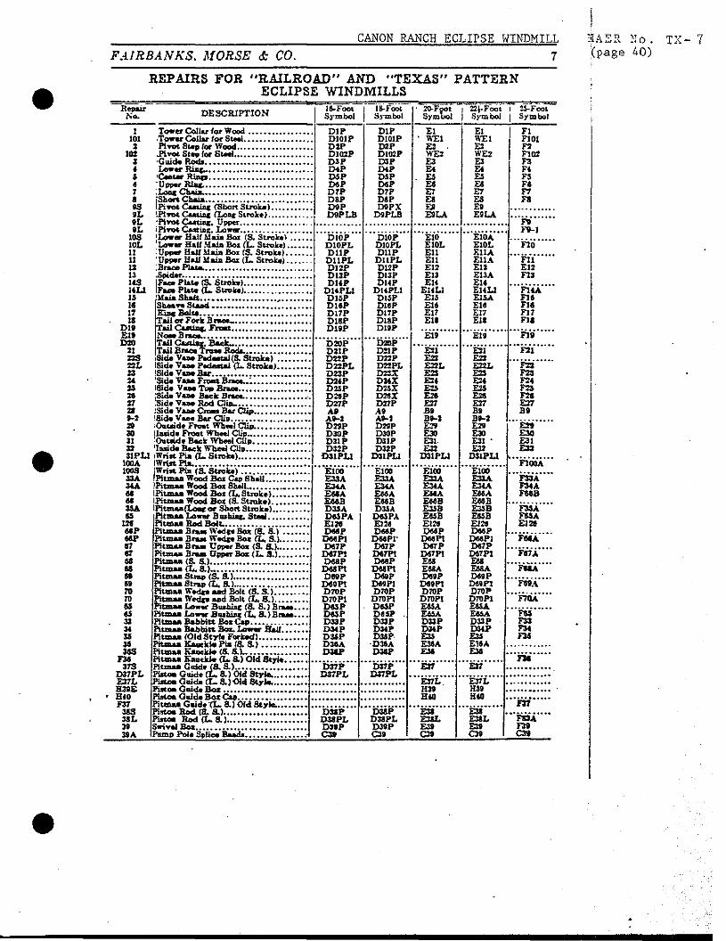
REPAIRS FOR 'RAILROAD" AND "TEXAS" PATTERN ECLIPSE WINDMILLS
Repair No. DESCRIPTION Symbol
IS-Foot Symbol
■ 20-Fpot Symbol
1 22). Foot j Symbol
i 25-Foot | Symbol
1 DIP D101P D2P D1Q2P D3P D4P DSP DSP D7P DSP D9P DSP LB
DIP DI01P D2P D102P D3P D4P DSP DSP D7P DSP D9PX
D9PU3
El ' WEI
E2 . WE2 £3 £4
. ES £6 E7 E8 E9 E9LA
El WEI £2 WE2 E3 E4 E5 ES £7 £8 E9 E9LA
Fl 101 F101 1 F2
102 F102 3 F3 4 F4 & F5 a F« 7 F7 s FS 93 9L 9L F» BL F9-1
10S |Lo»«r Half ilaia Boi fS. Stroke! Lower Half Mais Bo* (L. Stroke) Upper Half Maia Bat (S. Stroke)
'Upper Half Main Box (L. Stroke)
D10P D10PL DI1P D11PL D12P D13P D14P
D14PL1 D15P DlflP D17P D18P D19P
D10P D10PL D11P
DUPL D12P DI3P DI4P
SI4PL1 DI5P DWP D17P DlSP D19P
E10 E10L Ell Ell £12 £13 £14
E14L1 El* E16 EJ7 £18
E10A ElOL El LA Ell A £12 E13A £14 E14L1 EISA E18 E17 E18
I0L 11
F10
11 13
Fll E12
13 F13 143 |F-i» Plate C5. S"*M 14U F14A 15 F14 IS F16 17 F17 18 F18
D19 £11 £19 E19 FIB D20 DZ0P
D21P D22P D22PL D23P D24P D2SP D2SP D27P A9 A9-2 D29P D30P D31P D42P
031PU
D20P D21P D22P D22PL D233C D24X D25X D28X D27P A9 A9-1 D29P D30P D31P D32P
D3IPU
21 £21 E22 E22L £23 £24 £25 £28 E27 B8 B9-2 E29 £30 E31- E32 □3IPL1
£31 E22 E22L £23 £24 £25 E28 E27 B9 B9-2 E28 £30 E31 ' E32
D31PU
F21 223 22X, F22 23 F23 24 F24 23 F25 26 F2S 27 £27 2S B9 9-2 29 £» 30 £30 31 £31 32 £32 31PU
100A F100A 1003 £100
E33A E34A E68A £008 D35A DSSPA £120 DWP
DMPl D«7P
D87P1 D«8P
DMPl DMP
D«9P1 D70P D70PI D«5P D«P D33P D34P D34P D34A D38P
ElOO E33A E34A EUA EMS DMA
DSSPA El 28 DWP
DMPl* DS7P DS7P1 Deep
DMPl D69P
DS9P1 D70P
D70P1 D6SP DoSP . D33P D34P D3SP DMA Doep
£100 E33A £34A EUA EWB E3SB ES5B EI2S DMP
DWPl DS7P
DS7P1 £68 EB8A DS9P
DMPl D70P D70PI E65A EUA D33P D34P £35 E30A £38
ElOO E33A E34A EUA EMS EUB E55B £12S DWP
DBSPl DS7P
DS7P1 £68 EUA D69P
D69P1 D70P D70P1 E4SA £«SA D33P D34F £3S £MA E38
33A F33A UA F34A
F»8 U 35A Pia&«a(loB* or Short Stroke) F35A AS F«SA
128 £128 HP UP 67
FMA
67 S3
F87A
68 F88A » B9 FMA 70 70 F7QA
Pitmaa Lower Btubiar. (3. 8.) Bra** Pitmaa Lower Buehisx; (L.SOBraae 63
23 Ftt F33
M 35
F34 F3S
39 PHmaa ICauckl* Pi» (8. 3.) 383 PfmH Kawkl* {*, «,)
F36 FM 373 D37P
D37PL D37P
D37PL £37 E37
D37PL E37JL E37X.
H39 H40
E37L H39 H40
H39E ' H40
F37 FIX D38P DMPL D39P C39
D3SP D38PL D39P C39
£38 E38L E39 C39 1
E3S £3SL E39 C39 1
SSL FS3A 39 F30 39A ! C3»

CANON RANCH ECLIPSE WINDMILL HAER No. TX-7 (page 41)
APPENDIX E
Fairbanks Morse Illustration
and Repair Parts List
1910 and 1914

CANON RANCH ECLIPSE WINDMILL • a'i" T <P^f 42>

UANUN KAJMCH ttCLlFSli WINDMILL |
f1to£ J9|<J- SAER No. TX-7 (page 43
8 FAIRBANKS, MORSE d- CO.
REPAIRS FOR "RAILROAD" AND "TEXAS" PATTERN ECLIPSE WINDMILLS —(Continued)
Rep«ir No. - DESCRIPTION
16-Foot Symbol
18-Foot Symbol
20-Foot Symbol
22J-Fool Symbol
25-Foot Symbol
39A A39 D40P D41P D42P
D43PS D44P E45 EMflP
/ E48 \ E4S-1
E49 E50 E51 E52 E53
Bap DS4PA
A3 9 D40P D4IP D42P D43PB D44P £43 D4BP £48 £48-1 E49 E50 £51 £52 £53 EM D55P DMPA
A39 E40 E41 £42 £43C E44 F45 E46 £48 £48-1 E49 E50 E51 E52 E43 £54 ES5 E58A £57 F5S F59 EM ESI E82 E83 FM
A39 E40 E41 £43 E43C £44 F45 £46 £48 E48-1 E40 E50 £51 E52 E53 £54 E55 E5SA £57 F58 FS9 EM ESI ES2 ES3 FM
A39 40 F« 41 F4I 42 * F42 43 F43B 44 F44 45 F45 46 F46 48 49
F43B F48-1 E49
50 EM 51 E51 53 TM 53 E53 M EM 55 £55 M 57
FMA F57
58 F58 59 F39 00 E60 ■
ESI .E62
C33
EW E«I EU C33
EM 61 EM S3 Re«vInline Stop (Itoasd HOIM) . £83 S3 E63 64 FM M FMA 73 D73P-
D73P D7*P D75P D76P D79P DS0P
D7JP D73P D74P D75P D76P D79P D80P
E72 E73 E74 E75 £76 E79 E30
E72 E73 E74 E75 ■ E78 £79 £80
F73 73 FT3 74 F74 75 F7SA 78 79L 80 81
FT9 F60 F81
90 b»p DfllP D92P
: D93P r»4p D95P
D90P D91P D92P DMP DMP DMP
£90 E91 DfllP D93P D04P D95P
£90 E91 D92P DMP D94P D95P
F90 9t FBI 93 ' " DMP 93- D93P 94 DMP 95 F95 97 F97 98 D98P
DMP D54A D103
D9SP D99P D54A D103X
E98A DB9P E154
ES8A D99P £154
F98 99 F99
103 F1S4 103A 103A E103A
EI03 E104 E105 E106 EI07 £108 E109 E110 Elll Em
E103X E103AX
El MX E105X E106X E107 , E10S E109 El 10 Em Em
FlCttA 103A F103 104 DIM
DI05 DIM DI07 D108 D10B
iSioix DI05X DlOSX D107
. XM0S D10B
F104 106 FI05 106 F106 107 F107 108 F108 109 F109 110 E110 111 Dill
El 12 Dill ElM
Fl« 113 F113 113 FllJ 114 114
Dili AIM
DIM A114
F114 Bin EllflA £117 Elll
.E119 E1S E133 -E124 £125 E127
F114 B114 E116A EU7 £118 E119 £122 E123 E134 £125 E127
F114 B1I4
116 F116 117 D117P
D11S E119 EI22
■ Dm DI24 DBS £127
D117P Dili Eua E122 D123 D134 DI2S £127
F117 118 Flit 1198 1228 133 F133 124 F124 129 F125 127 £127 129 M39 311 313 313
TireU Boud Stop (toad D311P D312P
D311P D312P
E3U £313
E311 £313
F311 F312 F313
314 F314 385 TA383 TAias TA383 TA38S TA3SS

HAER No. TX-T" page 44
.:-:. .-■;■'., ...,jf
i.
«t
FIELD RECORDS
HAER TX-7HAER TEX,186-SHEF.V,1-
ADDENDUM TO:CANON RANCH ECLIPSE WINDMILLSheffield vicinityPecos CountyTexas
HISTORIC AMERICAN ENGINEERING RECORDNational Park Service
U.S. Department of the Interior1849 C Street NW
Washington, DC 20240-0001