canopen - pudn.comread.pudn.com/downloads157/doc/comm/701058/cia... · cia draft standard 401...
TRANSCRIPT

CiA Draft Standard 401
CANopen Device prof i le for gener ic I /O modules
Version: 3.0
03 June 2008
CAN in Automation (CiA) e. V.

Device profile for generic I/O modules
2 CiA 2008 – All rights reserved
HISTORY
Date Changes 2002-05-17 Publication of version 2.1 as draft standard
2006-10-02 Publication of version 3.0 as draft standard proposal
- Editorial and lay-out changes have been made
- Object 1000h: Additional definitions
- Detailed definitions of PDO parameters have been included
- Additional PDO mapping for joystick devices
- Warning if analogue input global interrupt is disabled
- Additional dead-band objects for joystick devices
2008-06-03 Publication of version 3.0 as draft standard
General information on licensing and patents
CAN in AUTOMATION (CiA) calls attention to the possibility that some of the elements of this CiA specification may be subject of patent rights. CiA shall not be responsible for identifying any or all such patent rights. Because this specification is licensed free of charge, there is no warranty for this specification, to the extent permitted by applicable law. Except when otherwise stated in writing the copyright holder and/or other parties provide this specification “as is” without warranty of any kind, either expressed or implied, including, but not limited to, the implied warranties of merchantability and fitness for a particular purpose. The entire risk as to the correctness and completeness of the specification is with you. Should this specification prove failures, you assume the cost of all necessary servicing, repair or correction.
© CiA 2008
All rights reserved. Unless otherwise specified, no part of this publication may be reproduced or utilized in any form or by any means, electronic or mechanical, including photocopying and microfilm, without permission in writing from CiA at the address below. CAN in Automation e. V. Kontumazgarten 3 DE - 90429 Nuremberg, Germany Tel.: +49-911-928819-0 Fax: +49-911-928819-79 Url: www.can-cia.org Email: [email protected]

Device profile for generic I/O modules
CiA 2008 – All rights reserved 3
CONTENTS
1 Scope ...............................................................................................................................7 2 Normative references........................................................................................................7 3 Definitions and abbreviations ............................................................................................7
3.1 Definition .................................................................................................................7 3.2 Abbreviations...........................................................................................................7
4 Operating principle............................................................................................................7 4.1 Introduction .............................................................................................................7 4.2 Node-ID assignment ................................................................................................8
5 Error handling ...................................................................................................................8 5.1 Principle ..................................................................................................................8 5.2 Error behavior..........................................................................................................8 5.3 Analogue input disable warning ...............................................................................8 5.4 Additional error code definitions...............................................................................8
6 Pre-definitions...................................................................................................................9 6.1 Introduction .............................................................................................................9 6.2 Pre-defined communication objects .........................................................................9
6.2.1 Object 1000h: Device type............................................................................9 6.2.2 Object 1001h: Error register ....................................................................... 10 6.2.3 Object 1029h: Error behavior...................................................................... 10 6.2.4 RPDO 1 (digital outputs) ............................................................................ 11 6.2.5 TPDO 1 (digital inputs) .............................................................................. 13 6.2.6 RPDO 2 (analogue outputs) ....................................................................... 15 6.2.7 TPDO 2 (analogue inputs) ......................................................................... 17 6.2.8 RPDO 3 (additional analogue outputs) ....................................................... 19 6.2.9 TPDO 3 (additional analogue inputs) ......................................................... 22 6.2.10 RPDO 4 (additional analogue outputs) ....................................................... 24 6.2.11 TPDO 4 (additional analogue inputs) ......................................................... 26 6.2.12 Manufacturer-specific PDOs ...................................................................... 29
7 Object dictionary ............................................................................................................. 29 7.1 Introduction ........................................................................................................... 29 7.2 Input and output function principles ....................................................................... 29
7.2.1 Object dictionary for the digital input and output modules .......................... 29 7.2.2 Digital input module ................................................................................... 30 7.2.3 Digital output module ................................................................................. 31 7.2.4 Analogue input module .............................................................................. 31 7.2.5 Analogue output module ............................................................................ 32
8 Detailed object definitions ............................................................................................... 33 8.1 Introduction ........................................................................................................... 33 8.2 Digital input module ............................................................................................... 33
8.2.1 Object 6000h: Read input 8-bit ................................................................... 33 8.2.2 Object 6002h: Polarity input 8-bit ............................................................... 35 8.2.3 Object 6003h: Filter constant input 8-bit ..................................................... 36 8.2.4 Object 6005h: Global interrupt enable digital 8-bit ...................................... 37 8.2.5 Object 6006h: Interrupt mask any change 8-bit........................................... 38 8.2.6 Object 6007h: Interrupt mask low-to-high 8-bit ........................................... 39 8.2.7 Object 6008h: Interrupt mask high-to-low 8-bit ........................................... 40

Device profile for generic I/O modules
4 CiA 2008 – All rights reserved
8.2.8 Object 6020h to 6027h: Read input bit 1 to 128 to read input bit 897 to 1024 .......................................................................................................... 41
8.2.9 Object 6030h to 6037h: Polarity input bit 1 to 128 to polarity input bit 897 to 1024 ............................................................................................... 43
8.2.10 Object 6038h to 603Fh: Filter constant input bit 1 to 128 to filter constant input bit 897 to 1024.................................................................... 44
8.2.11 Object 6050h to 6057h: Interrupt mask input bit any change 1 to 128 to interrupt mask input bit any change 897 to 1024 .................................... 45
8.2.12 Object 6060h to 6067h: Interrupt mask input low-to-high bit 1 to 128 to interrupt mask input low-to-high bit 897 to 1024..................................... 46
8.2.13 Object 6070h to 6077h: Interrupt mask input high-to-low bit 1 to 128 to interrupt mask input high-to-low bit 897 to 1024..................................... 47
8.2.14 Object 6100h: Read input 16-bit ................................................................. 49 8.2.15 Object 6102h: Polarity input 16-bit ............................................................. 50 8.2.16 Object 6103h: Filter constant input 16-bit ................................................... 51 8.2.17 Object 6106h: Interrupt mask input any change 16-bit ................................ 52 8.2.18 Object 6107h: Interrupt mask input low-to-high 16-bit ................................. 53 8.2.19 Object 6108h: Interrupt mask input high-to-low 16-bit ................................. 55 8.2.20 Object 6120h: Read input 32-bit ................................................................. 56 8.2.21 Object 6122h: Polarity input 32-bit ............................................................. 57 8.2.22 Object 6123h: Filter constant input 32-bit ................................................... 58 8.2.23 Object 6126h: Interrupt mask input any change 32-bit ................................ 59 8.2.24 Object 6127h: Interrupt mask input low-to-high 32-bit ................................. 61 8.2.25 Object 6128h: Interrupt mask input high-to-low 32-bit ................................. 62
8.3 Digital output module ............................................................................................. 63 8.3.1 Object 6200h: Write output 8-bit ................................................................. 63 8.3.2 Object 6202h: Change polarity output 8-bit................................................. 64 8.3.3 Object 6206h: Error mode output 8-bit........................................................ 66 8.3.4 Object 6207h: Error value output 8-bit ........................................................ 67 8.3.5 Object 6208h: Filter mask output 8-bit ........................................................ 68 8.3.6 Object 6220h to 6227h: Write output bit 1 to 128 to write output bit
897 to 1024 ............................................................................................... 69 8.3.7 Object 6240h to 6247h: Change polarity output bit 1 to 128 to change
polarity output bit 897 to 1024 ................................................................... 70 8.3.8 Object 6250h to 6257h: Error mode output lines 1 to 128 to error
mode output lines 897 to 1024................................................................... 71 8.3.9 Object 6260h to 6267h: Error value output bit 1 to 128 to error value
output bit 897 to 1024................................................................................ 73 8.3.10 Object 6270h to 6277h: Filter mask output bit 1 to 128 to filter mask
output bit 897 to 1024................................................................................ 74 8.3.11 Object 6300h: Write output 16-bit ............................................................... 75 8.3.12 Object 6302h: Change polarity output 16-bit............................................... 76 8.3.13 Object 6306h: Error mode output 16-bit...................................................... 78 8.3.14 Object 6307h: Error value output 16-bit ...................................................... 79 8.3.15 Object 6308h: Filter mask output 16-bit ...................................................... 80 8.3.16 Object 6320h: Write output 32-bit ............................................................... 81 8.3.17 Object 6322h: Change polarity output 32-bit............................................... 82 8.3.18 Object 6326h: Error mode output 32-bit...................................................... 84 8.3.19 Object 6327h: Error value output 32-bit ...................................................... 85 8.3.20 Object 6328h: Filter mask output 32-bit ...................................................... 86
8.4 Analogue input module .......................................................................................... 87

Device profile for generic I/O modules
CiA 2008 – All rights reserved 5
8.4.1 Object 6400h: Read analogue input 8-bit.................................................... 87 8.4.2 Object 6401h: Read analogue input 16-bit .................................................. 88 8.4.3 Object 6402h: Read analogue input 32-bit .................................................. 90 8.4.4 Object 6403h: Read analogue input float .................................................... 91 8.4.5 Object 6404h: Read manufacturer-specific analogue input ......................... 92
8.5 Analogue output module ........................................................................................ 94 8.5.1 Object 6410h: Write analogue output 8-bit.................................................. 94 8.5.2 Object 6411h: Write analogue output 16-bit ................................................ 95 8.5.3 Object 6412h: Write analogue output 32-bit ................................................ 96 8.5.4 Object 6413h: Write analogue output float .................................................. 97 8.5.5 Object 6414h: Write manufacturer-specific analogue output ....................... 99
8.6 Analogue input set-ups ........................................................................................ 100 8.6.1 Object 6420h............................................................................................ 100 8.6.2 Object 6421h: Analogue input interrupt trigger selection........................... 100 8.6.3 Object 6422h: Analogue input interrupt source ......................................... 101 8.6.4 Object 6423h: Analogue input global interrupt enable ............................... 103 8.6.5 Object 6424h: Analogue input interrupt upper limit integer........................ 103 8.6.6 Object 6425h: Analogue input interrupt lower limit integer ........................ 104 8.6.7 Object 6426h: Analogue input interrupt delta unsigned ............................. 106 8.6.8 Object 6427h: Analogue input interrupt negative delta unsigned............... 107 8.6.9 Object 6428h: Analogue input interrupt positive delta unsigned ................ 108 8.6.10 Object 6429h: Analogue input interrupt upper limit float ........................... 109 8.6.11 Object 642Ah: Analogue input interrupt lower limit float............................ 110 8.6.12 Object 642Bh: Analogue input interrupt delta float.................................... 112 8.6.13 Object 642Ch: Analogue input interrupt negative delta float ..................... 113 8.6.14 Object 642Dh: Analogue input interrupt positive delta float....................... 114 8.6.15 Object 642Eh: Analogue input offset float................................................. 115 8.6.16 Object 642Fh: Analogue input pre-scaling float ........................................ 116 8.6.17 Object 6430h: Analogue input SI unit ....................................................... 118 8.6.18 Object 6431h: Analogue input offset integer ............................................. 119 8.6.19 Object 6432h: Analogue input pre-scaling integer..................................... 120
8.7 Analogue output set-ups ...................................................................................... 121 8.7.1 Object 6440h............................................................................................ 121 8.7.2 Object 6441h: Analogue output offset float ............................................... 121 8.7.3 Object 6442h: Analogue output scaling float ............................................. 123 8.7.4 Object 6443h: Analogue output error mode .............................................. 124 8.7.5 Object 6444h: Analogue output error value integer ................................... 125 8.7.8 Object 6445h: Analogue output error value float ....................................... 126 8.7.9 Object 6446h: Analogue output offset integer ........................................... 128 8.7.10 Object 6447h: Analogue output scaling integer......................................... 129 8.7.11 Object 6450h: Analogue output SI unit ..................................................... 130
8.8 General device profile objects.............................................................................. 131 8.8.1 Object 67FFh: Device type ....................................................................... 131
Annex A : Joystick .............................................................................................................. 132 A.1 Scope........................................................................................................................... 132 A.2 Pre-defined communication objects for joysticks........................................................... 132
A.2.1 Object 1000h: Device type ................................................................................... 132 A.3 Joystick buttons............................................................................................................ 132

Device profile for generic I/O modules
6 CiA 2008 – All rights reserved
A.4 Joystick proportional inputs .......................................................................................... 132 A.5 Joystick PDO mappings................................................................................................ 132
A.5.1 Introduction ......................................................................................................... 132 A.5.2 1st TPDO mapping (buttons) ............................................................................... 133 A.5.3 2nd TPDO mapping (proportional inputs)............................................................. 133 A.5.4 Specific PDO mapping for 3-D joysticks............................................................... 133 A.5.5 Specific PDO mapping for 2-D joysticks............................................................... 133
A.6 Joystick signal conditioning .......................................................................................... 134 A.6.1 Introduction ......................................................................................................... 134 A.6.2 Object 6460h: Analogue input dead-band unsigned.............................................. 134 A.6.3 Object 6461h: Analogue input dead-band float ..................................................... 135 A.6.4 Object 6462h: Analogue input post-scaling unsigned ........................................... 136 A.6.5 Object 6463h: Analogue input post-scaling float................................................... 138
A.7 Joystick implementation hints ....................................................................................... 139 A.7.1 Periodical PDO transmission ............................................................................... 139 A.7.2 Additional proportional inputs .............................................................................. 139 A.7.3 Transmission of proportional inputs ..................................................................... 139

Device profile for generic I/O modules
CiA 2008 – All rights reserved 7
1 Scope
This specification represents the CANopen device profile for generic digital and analogue input and output modules. Devices compliant to this specification use communication techniques, which conform to those described in the CANopen application layer and communication profile specification. In addition, programmable I/O devices may use communication techniques, which conform to those described in the CANopen additional application layer functions.
In the appendices, some specific I/O devices are defined.
2 Normative references
/CiA301/ CiA 301, CANopen application layer and communication profile
/CiA303-2/ CiA 303-2, CANopen additional specification – Part 2: Representation of SI units and prefixes
/CiA305/ CiA 305, CANopen layer setting services
3 Definitions and abbreviations
3.1 Definition
The definitions given in /CiA301/ and /CiA303-2/ apply for this specification, too.
3.2 Abbreviations
CAN Controller area network CAN-ID CAN identifier COB Communication object COB-ID COB identifier I/O Input and output PDO Process data object RPDO Receive process data object SDO Service data object TPDO Transmit process data object
4 Operating principle
4.1 Introduction
The purpose of I/O modules is to connect sensors and actuators to CANopen networks. In NMT operational mode, input data are transmitted from the inputs via TPDOs. By default, the PDO transmission is triggered by an interrupt (event). Optionally PDOs are transmitted synchronously or remotely requested. In addition, it is possible to read input data via SDO communication from another module, or to write data via SDO to the network, if the module provides SDO client functionality.
Output data can be received via RPDO by those I/O modules that have output capabilities. Output data also can be received via SDO communication services.
However, the main purpose of SDO communication is to configure an I/O module. The module can receive via SDO I/O configuration data, parameters for converting data into meaningful measurements and so on. I/O modules compliant with this device profile use pre-defined

Device profile for generic I/O modules
8 CiA 2008 – All rights reserved
PDOs. The default mapping of application objects into TPDO respectively RPDO is changeable via SDO, if variable PDO mapping is supported. An I/O module provides optionally sync producer/consumer, time-stamp producer/consumer and emergency producer/consumer functionality. For new designs, it is recommended to support Heartbeat functionality.
4.2 Node-ID assignment
The node-ID assignment is manufacturer specific. If a node-ID assignment via CAN network is required (e.g. for IP 67-rated devices), it is recommended to use the layer setting protocols as defined in /CiA305/.
5 Error handling
5.1 Principle
Emergency messages are triggered by internal errors in the device and they are assigned the highest possible priority to ensure that they get access to the bus without latency. By default, the Emergency messages contain the error field with pre-defined error numbers and additional information.
5.2 Error behavior
If a serious device failure is detected the module shall enter by default autonomously the Pre-operational state. If 1029h object is implemented, the device may be configured to enter alternatively the Stopped state or remain in the current state in case of a device failure. Device failures should include the following communication errors:
• Bus-off conditions of the CAN interface
• Life guarding event with the state ‘occurred’ • Heartbeat event with state ‘occurred’
Severe device errors also may be caused by device internal failures.
5.3 Analogue input disable warning
If the CANopen device transits to NMT operational state and the Analogue input global interrupt object (6423h) is set to FALSE, it shall transmit an Emergency message with the error code 0080h. This Emergency message shall not cause a transition into NMT pre-operational or NMT stopped state.
5.4 Additional error code definitions
Error code definitions used by this profile are given in Table 1.
Table 1 — Error code definition
Error code
Definition
0080h Warning: Analogue inputs disabled
2310h
2320h
2330h
Current at outputs too high (overload)
Short circuit at outputs
Load dump at outputs
3110h
3120h
3210h
Input voltage too high
Input voltage too low
Internal voltage too high

Device profile for generic I/O modules
CiA 2008 – All rights reserved 9
Error code
Definition
3220h
3310h
3320h
Internal voltage too low
Output voltage too high
Output voltage too low
6 Pre-definitions
6.1 Introduction
If a device supports a specific type of I/O functionality (analogue/digital I/O) it shall support the related default PDOs. However, the module may support additional manufacturer-specific PDOs. If variable PDO mapping is supported the PDO default settings may be changed by means of configuration.
There may be implemented up to 4 enabled TPDOs and up to 4 enabled RPDOs with default mappings. If a module does not support a specific I/O function, the related default PDOs shall remain unused. If a device supports more than the pre-mapped digital input or output channels, the analogue default PDOs shall not be used to map digital inputs or outputs by default. The additional digital I/Os may use additional PDOs. This shall correspond to additional analogue channels.
All TPDOs with transmission type 255 shall be transmitted when entering the operational state.
6.2 Pre-defined communication objects
Devices compliant with this specification come with default values for some communication objects (1000h to 1FFFh), which are not specified in all details in /CiA301/.
6.2.1 Object 1000h: Device type
This object describes the type of device and its functionality. For multiple device modules the additional information field shall contain FFFFh. In this case, the 67FFh object shall be implemented. Figure 1 shows the value structure as defined in /CiA301/ and defines the additional information field. Table 2 defines the values for the fields I/O functionality and M. The pre-defined, generic PDO mapping is described in this specification, the device-specific PDO mapping is not in the scope of this specification.
31 24 23 22 16 15 0
Specific functionality
M I/O functionality Device profile number
Additional information General information
MSB LSB
Figure 1 — Value structure
Table 2 — Value definition for I/O functionality and M
Field name Definition
Device profile number 401d
I/O functionality – Bit 16 1b = digital input(s) implemented 0b = not implemented
I/O functionality – Bit 17 1b = digital output(s) implemented 0b = not implemented
I/O functionality – Bit 18 1b = analogue input(s) implemented 0b = not implemented
I/O functionality – Bit 19 1b = analogue output(s) implemented 0b = not implemented

Device profile for generic I/O modules
10 CiA 2008 – All rights reserved
Field name Definition
I/O functionality – Bit 20 to Bit 22 Reserved
M(apping of PDOs) 1b = Device-specific PDO mapping is supported 0b = Pre-defined, generic PDO mapping is supported (see 6.2.4 to 6.2.11)
NOTE Any combination of digital/analogue, inputs and outputs is allowed; one of the bits 16 to 19 shall be 1b.
Table 3 defines the values of the specific functionality sub-field.
Table 3 — Value definition for the specific functionality
Code Function Reference
00h No specific function -
01h Joystick Appendix A
02h Joystick Appendix A
03h Joystick Appendix A
04h to FFh Reserved -
6.2.2 Object 1001h: Error register
The device-specific bit in the status byte is reserved for future use.
6.2.3 Object 1029h: Error behavior
The object specifies to which state an I/O module shall be set, when a communication error, output error or input error is detected. The following values are defined, all others are reserved:
00h = transit to NMT pre-operational (only if the current NMT state is operational) state 01h = remain in current NMT state 02h = transit to NMT stopped state
In addition to the specification in /CiA301/ the following sub-indices may be implemented.
Table 4 specifies the entry description.
Table 4 — Entry description
Attribute Value
Sub-Index 02h
Description Output error
Access rw
Entry category Optional
PDO mapping No
Value range 00h to 02h
Default value 00h

Device profile for generic I/O modules
CiA 2008 – All rights reserved 11
Sub-Index 03h
Description Input error
Access rw
Entry category Optional
PDO mapping No
Value range 00h to 02h
Default value 00h
NOTE If the object 1029h is not implemented, the device behaves in case of communication, input or output failures as defined by the default value.
6.2.4 RPDO 1 (digital outputs)
This RPDO receives the values of up to 64 digital outputs.
NOTE After power-on and application reset the values of the mapped outputs are as the default values or the stored values after configuration (stored values overwrites default values).
Table 5 defines the object description and Table 6 defines the entry description of the RPDO communication parameter.
Table 5 — Object description
Attribute Value
INDEX 1400h
Name RPDO 1 communication parameter
Object code Record
Data type PDO communication parameter record
Category Conditional: Mandatory, if M-bit in object 1000h is set to 0b and bit 17 in object 1000h is set to 1b
Table 6 — Entry description
Attribute Value
Sub-Index 00h
Description Highest sub-index supported
Access ro
Entry category Mandatory
PDO mapping No
Value range 02h
Default value 02h
Sub-Index 01h
Description COB-ID
Access rw
Entry category Mandatory
PDO mapping No
Value range See /CiA301/
Default value 0000 0200h + node-ID

Device profile for generic I/O modules
12 CiA 2008 – All rights reserved
Sub-Index 02h
Description Transmission type
Access rw
Entry category Mandatory
PDO mapping No
Value range See /CiA301/
Default value 255d
Table 7 defines the object description and Table 8 defines the entry description of the RPDO mapping parameter. The number of mapped objects into this RPDO depends on the hardware.
Table 7 — Object description
Attribute Value
INDEX 1600h
Name RPDO 1 mapping parameter
Object code Record
Data type PDO mapping parameter record
Category Conditional: Mandatory, if 1400h is implemented
Table 8 — Entry description
Attribute Value
Sub-Index 00h
Description Highest sub-index supported
Access rw
Entry category Mandatory
PDO mapping No
Value range 01h to 08h
Default value 01h to 08h
Sub-Index 01h
Description 1st application object
Access rw
Entry category Mandatory
PDO mapping No
Value range See /CiA301/
Default value 6200 01 08h
Sub-Index 02h
Description 2nd application object
Access rw
Entry category Conditional: Mandatory, if object 6200 02h is implemented
PDO mapping No
Value range See /CiA301/
Default value 6200 02 08h
to

Device profile for generic I/O modules
CiA 2008 – All rights reserved 13
Sub-Index 08h
Description 8th application object
Access rw
Entry category Conditional: Mandatory, if object 6200 08h is implemented
PDO mapping No
Value range See /CiA301/
Default value 6200 08 08h
6.2.5 TPDO 1 (digital inputs)
This TPDO transmits event-driven the values of maximum 64 digital inputs. If one digital input changes its value, this PDO shall be transmitted immediately. If an interrupt mask is enabled, the PDO shall be transmitted only if the interrupt condition is fulfilled.
Table 9 defines the object description and Table 10 defines the entry description of the TPDO communication parameter. The values are defined in /CiA301/. The sub-index 04h is reserved for compatibility reasons and shall not be implemented.
Table 9 — Object description
Attribute Value
INDEX 1800h
Name TPDO 1 communication parameter
Object code Record
Data type PDO communication parameter record
Category Conditional: Mandatory, if M-bit in object 1000h is set to 0b and bit 16 in object 1000h is set to 1b
Table 10 — Entry description
Attribute Value
Sub-Index 00h
Description Highest sub-index supported
Access ro
Entry category Mandatory
PDO mapping No
Value range 02h to 05h
Default value Manufacturer-specific
Sub-Index 01h
Description COB-ID used by PDO
Access rw
Entry category Mandatory
PDO mapping No
Value range See /CiA301/
Default value {0000 0180h, 4000 0180h} + node-ID

Device profile for generic I/O modules
14 CiA 2008 – All rights reserved
Sub-Index 02h
Description Transmission type
Access rw
Entry category Mandatory
PDO mapping No
Value range See /CiA301/
Default value 255d
Sub-Index 03h
Description Inhibit time
Access rw
Entry category Optional
PDO mapping No
Value range See /CiA301/
Default value 00h
Sub-Index 05h
Description Event timer
Access rw
Entry category Optional
PDO mapping No
Value range See /CiA301/
Default value 00h
Table 11 defines the object description and Table 12 defines the entry description of the TPDO mapping parameter. The number of mapped objects into this TPDO depends on the hardware.
Table 11 — Object description
Attribute Value
INDEX 1A00h
Name TPDO 1 mapping parameter
Object code Record
Data type PDO mapping parameter record
Category Conditional: Mandatory, if 1800h is implemented
Table 12 — Entry description
Attribute Value
Sub-Index 00h
Description Highest sub-index supported
Access rw
Entry category Mandatory
PDO mapping No
Value range 01h to 08h
Default value 01h to 08h

Device profile for generic I/O modules
CiA 2008 – All rights reserved 15
Sub-Index 01h
Description 1st application object
Access rw
Entry category Mandatory
PDO mapping No
Value range See /CiA301/
Default value 6000 01 08h
Sub-Index 02h
Description 2nd application object
Access rw
Entry category Conditional: Mandatory, if object 6000 02h is implemented
PDO mapping No
Value range See /CiA301/
Default value 6000 02 08h
to
Sub-Index 08h
Description 8th application object
Access rw
Entry category Conditional: Mandatory, if object 6000 08h is implemented
PDO mapping No
Value range See /CiA301/
Default value 6000 08 08h
6.2.6 RPDO 2 (analogue outputs)
This RPDO receives asynchronously the 16-bit values of maximum 4 analogue outputs to the module. The default transmission type shall be 255.
NOTE After power-on and application reset the values of the mapped outputs are as the default values or the stored values after configuration (stored values overwrites default values).
Table 13 defines the object description and Table 14 defines the entry description of the RPDO communication parameter.
Table 13 — Object description
Attribute Value
INDEX 1401h
Name RPDO 2 communication parameter
Object code Record
Data type PDO communication parameter record
Category Conditional: Mandatory, if M-bit in object 1000h is set to 0b and bit 19 in object 1000h is set to 1b
Table 14 — Entry description
Attribute Value

Device profile for generic I/O modules
16 CiA 2008 – All rights reserved
Sub-Index 00h
Description Highest sub-index supported
Access ro
Entry category Mandatory
PDO mapping No
Value range 02h
Default value 02h
Sub-Index 01h
Description COB-ID
Access rw
Entry category Mandatory
PDO mapping No
Value range See /CiA301/
Default value 0000 0300h + node-ID
Sub-Index 02h
Description Transmission type
Access rw
Entry category Mandatory
PDO mapping No
Value range See /CiA301/
Default value 255d
Table 15 defines the object description and Table 16 defines the entry description of the RPDO mapping parameter. The number of mapped objects into this RPDO depends on the hardware.
Table 15 — Object description
Attribute Value
INDEX 1601h
Name RPDO 2mapping parameter
Object code Record
Data type PDO mapping parameter record
Category Conditional: Mandatory, if 1401h is implemented
Table 16 — Entry description
Attribute Value
Sub-Index 00h
Description Highest sub-index supported
Access rw
Entry category Mandatory
PDO mapping No
Value range 01h to 04h
Default value 01h to 04h

Device profile for generic I/O modules
CiA 2008 – All rights reserved 17
Sub-Index 01h
Description 1st application object
Access rw
Entry category Mandatory
PDO mapping No
Value range See /CiA301/
Default value 6411 01 10h
Sub-Index 02h
Description 2nd application object
Access rw
Entry category Conditional: Mandatory, if object 6411 02h is implemented
PDO mapping No
Value range See /CiA301/
Default value 6411 02 10h
to
Sub-Index 04h
Description 4th application object
Access rw
Entry category Conditional: Mandatory, if object 6411 04h is implemented
PDO mapping No
Value range See /CiA301/
Default value 6411 04 10h
6.2.7 TPDO 2 (analogue inputs)
This TPDO transmits event-driven the 16-bit values of maximum 4 analogue inputs. By default the interrupt source (6423h object) shall be disabled. If one of the mapped analogue input changes its value and 6423h object is enabled, the PDO is transmitted immediately. If an analogue interrupt condition is enabled, the PDO is transmitted only if this interrupt condition is fulfilled. If more than one interrupt condition is enabled; the PDO is transmitted if one of these conditions is fulfilled.
Table 17 defines the object description and Table 18 defines the entry description of the TPDO communication parameter. The values are defined in /CiA301/. The sub-index 04h is reserved for compatibility reasons and shall not be implemented.
Table 17 — Object description
Attribute Value
INDEX 1801h
Name TPDO 2 communication parameter
Object code Record
Data type PDO communication parameter record
Category Conditional: Mandatory, if M-bit in object 1000h is set to 0b and bit 18 in object 1000h is set to 1b

Device profile for generic I/O modules
18 CiA 2008 – All rights reserved
Table 18 — Entry description
Attribute Value
Sub-Index 00h
Description Highest sub-index supported
Access ro
Entry category Mandatory
PDO mapping No
Value range 02h to 05h
Default value Manufacturer-specific
Sub-Index 01h
Description COB-ID
Access rw
Entry category Mandatory
PDO mapping No
Value range See /CiA301/
Default value {0000 0280h, 4000 0280h} + node-ID
Sub-Index 02h
Description Transmission type
Access rw
Entry category Mandatory
PDO mapping No
Value range See /CiA301/
Default value 255d
Sub-Index 03h
Description Inhibit time
Access rw
Entry category Optional
PDO mapping No
Value range See /CiA301/
Default value 00h
Sub-Index 05h
Description Event timer
Access rw
Entry category Optional
PDO mapping No
Value range See /CiA301/
Default value 00h
Table 19 defines the object description and Table 20 defines the entry description of the TPDO mapping parameter. The number of mapped objects into this TPDO depends on the hardware.

Device profile for generic I/O modules
CiA 2008 – All rights reserved 19
Table 19 — Object description
Attribute Value
INDEX 1A01h
Name TPDO 2 mapping parameter
Object code Record
Data type PDO mapping parameter record
Category Conditional: Mandatory, if 1801h is implemented
Table 20 — Entry description
Attribute Value
Sub-Index 00h
Description Highest sub-index supported
Access rw
Entry category Mandatory
PDO mapping No
Value range 01h to 04h
Default value 01h to 04h
Sub-Index 01h
Description 1st application object
Access rw
Entry category Mandatory
PDO mapping No
Value range See /CiA301/
Default value 6401 01 10h
Sub-Index 02h
Description 2nd application object
Access rw
Entry category Conditional: Mandatory, if object 6401 02h is implemented
PDO mapping No
Value range See /CiA301/
Default value 6401 02 10h
to
Sub-Index 04h
Description 4th application object
Access rw
Entry category Conditional: Mandatory, if object 6401 04h is implemented
PDO mapping No
Value range See /CiA301/
Default value 6401 04 10h
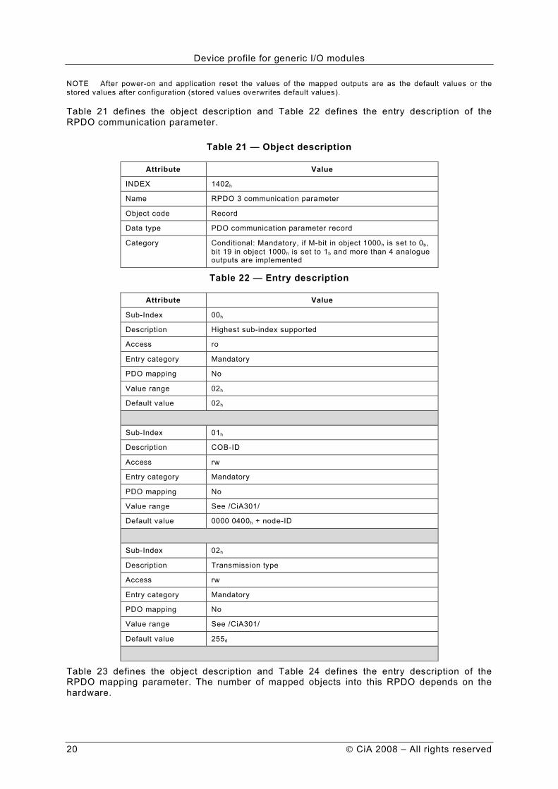
6.2.8 RPDO 3 (additional analogue outputs)
This RPDO receives asynchronously the 16-bit values of maximum 4 analogue outputs.
Device profile for generic I/O modules
20 CiA 2008 – All rights reserved
NOTE After power-on and application reset the values of the mapped outputs are as the default values or the stored values after configuration (stored values overwrites default values).
Table 21 defines the object description and Table 22 defines the entry description of the RPDO communication parameter.
Table 21 — Object description
Attribute Value
INDEX 1402h
Name RPDO 3 communication parameter
Object code Record
Data type PDO communication parameter record
Category Conditional: Mandatory, if M-bit in object 1000h is set to 0b, bit 19 in object 1000h is set to 1b and more than 4 analogue outputs are implemented
Table 22 — Entry description
Attribute Value
Sub-Index 00h
Description Highest sub-index supported
Access ro
Entry category Mandatory
PDO mapping No
Value range 02h
Default value 02h
Sub-Index 01h
Description COB-ID
Access rw
Entry category Mandatory
PDO mapping No
Value range See /CiA301/
Default value 0000 0400h + node-ID
Sub-Index 02h
Description Transmission type
Access rw
Entry category Mandatory
PDO mapping No
Value range See /CiA301/
Default value 255d
Table 23 defines the object description and Table 24 defines the entry description of the RPDO mapping parameter. The number of mapped objects into this RPDO depends on the hardware.
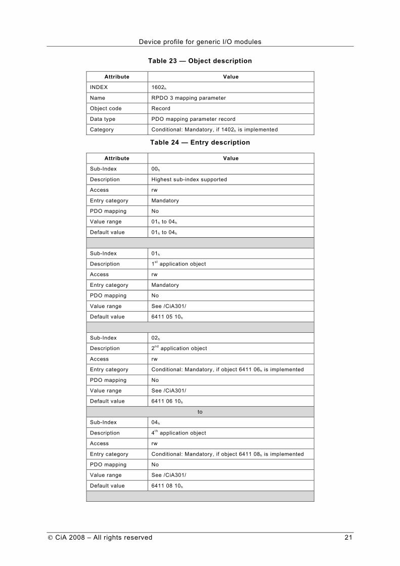
Device profile for generic I/O modules
CiA 2008 – All rights reserved 21
Table 23 — Object description
Attribute Value
INDEX 1602h
Name RPDO 3 mapping parameter
Object code Record
Data type PDO mapping parameter record
Category Conditional: Mandatory, if 1402h is implemented
Table 24 — Entry description
Attribute Value
Sub-Index 00h
Description Highest sub-index supported
Access rw
Entry category Mandatory
PDO mapping No
Value range 01h to 04h
Default value 01h to 04h
Sub-Index 01h
Description 1st application object
Access rw
Entry category Mandatory
PDO mapping No
Value range See /CiA301/
Default value 6411 05 10h
Sub-Index 02h
Description 2nd application object
Access rw
Entry category Conditional: Mandatory, if object 6411 06h is implemented
PDO mapping No
Value range See /CiA301/
Default value 6411 06 10h
to
Sub-Index 04h
Description 4th application object
Access rw
Entry category Conditional: Mandatory, if object 6411 08h is implemented
PDO mapping No
Value range See /CiA301/
Default value 6411 08 10h

Device profile for generic I/O modules
22 CiA 2008 – All rights reserved
6.2.9 TPDO 3 (additional analogue inputs)
This TPDO transmits event-driven the 16-bit values of maximum 4 analogue inputs. By default the interrupt source (6423h object) is disabled. If one of the mapped analogue input changes its value and 6423h object is enabled, the PDO is transmitted immediately. If an analogue interrupt condition is enabled; the PDO is transmitted only if this interrupt condition is fulfilled. If more than one interrupt condition is enabled; the PDO is transmitted if one of these conditions is fulfilled.
Table 25 defines the object description and Table 26 defines the entry description of the TPDO communication parameter. The values are defined in /CiA301/. The sub-index 04h is reserved for compatibility reasons and shall not be implemented.
Table 25 — Object description
Attribute Value
INDEX 1802h
Name TPDO 3 communication parameter
Object code Record
Data type PDO communication parameter record
Category Conditional: Mandatory, if M-bit in object 1000h is set to 0b, bit 18 in object 1000h is set to 1b and more than 4 analogue inputs are implemented
Table 26 — Entry description
Attribute Value
Sub-Index 00h
Description Highest sub-index supported
Access ro
Entry category Mandatory
PDO mapping No
Value range 02h to 05h
Default value Manufacturer-specific
Sub-Index 01h
Description COB-ID
Access rw
Entry category Mandatory
PDO mapping No
Value range See /CiA301/
Default value {0000 0380h, 4000 0380h} + node-ID
Sub-Index 02h
Description Transmission type
Access rw
Entry category Mandatory
PDO mapping No
Value range See /CiA301/
Default value 255d

Device profile for generic I/O modules
CiA 2008 – All rights reserved 23
Sub-Index 03h
Description Inhibit timer
Access rw
Entry category Optional
PDO mapping No
Value range See /CiA301/
Default value 00h
Sub-Index 05h
Description Event timer
Access rw
Entry category Optional
PDO mapping No
Value range See /CiA301/
Default value 00h
Table 27 defines the object description and Table 28 defines the entry description of the TPDO mapping parameter. The number of mapped objects into this TPDO depends on the hardware.
Table 27 — Object description
Attribute Value
INDEX 1A02h
Name TPDO 3 mapping parameter
Object code Record
Data type PDO mapping parameter record
Category Conditional: Mandatory, if 1802h is implemented
Table 28 — Entry description
Attribute Value
Sub-Index 00h
Description Highest sub-index supported
Access rw
Entry category Mandatory
PDO mapping No
Value range 01h to 04h
Default value 01h to 04h

Device profile for generic I/O modules
24 CiA 2008 – All rights reserved
Sub-Index 01h
Description 1st application object
Access rw
Entry category Mandatory
PDO mapping No
Value range See /CiA301/
Default value 6401 05 10h
Sub-Index 02h
Description 2nd application object
Access rw
Entry category Conditional: Mandatory, if object 6401 06h is implemented
PDO mapping No
Value range See /CiA301/
Default value 6401 06 10h
to
Sub-Index 04h
Description 4th application object
Access rw
Entry category Conditional: Mandatory, if object 6401 08h is implemented
PDO mapping No
Value range See /CiA301/
Default value 6401 08 10h
6.2.10 RPDO 4 (additional analogue outputs)
This RPDO receives asynchronously the 16-bit values of maximum 4 analogue outputs. The default transmission type shall be 255.
Note After power-on and application reset the values of the mapped outputs are as the default values or the stored values after configuration (stored values overwrites default values).
Table 29 defines the object description and Table 30 defines the entry description of the RPDO communication parameter.
Table 29 — Object description
Attribute Value
INDEX 1403h
Name RPDO 4 communication parameter
Object code Record
Data type PDO communication parameter record
Category Conditional: Mandatory, if M-bit in object 1000h is set to 0b, bit 19 in object 1000h is set to 1b and more than 8 analogue outputs are implemented
Table 30 — Entry description
Attribute Value

Device profile for generic I/O modules
CiA 2008 – All rights reserved 25
Sub-Index 00h
Description Highest sub-index supported
Access ro
Entry category Mandatory
PDO mapping No
Value range 02h
Default value 02h
Sub-Index 01h
Description COB-ID
Access rw
Entry category Mandatory
PDO mapping No
Value range See /CiA301/
Default value 0000 0500h + node-ID
Sub-Index 02h
Description Transmission type
Access rw
Entry category Mandatory
PDO mapping No
Value range See /CiA301/
Default value 255d
Table 31 defines the object description and Table 32 defines the entry description of the RPDO mapping parameter. The number of mapped objects into this RPDO depends on the hardware.
Table 31 — Object description
Attribute Value
INDEX 1603h
Name RPDO 4 mapping parameter
Object code Record
Data type PDO mapping parameter record
Category Conditional: Mandatory, if 1403h is implemented
Table 32 — Entry description
Attribute Value
Sub-Index 00h
Description Highest sub-index supported
Access rw
Entry category Mandatory
PDO mapping No
Value range 01h to 04h
Default value 01h to 04h

Device profile for generic I/O modules
26 CiA 2008 – All rights reserved
Sub-Index 01h
Description 1st application object
Access rw
Entry category Mandatory
PDO mapping No
Value range See /CiA301/
Default value 6411 09 10h
Sub-Index 02h
Description 2nd application object
Access rw
Entry category Conditional: Mandatory, if object 6411 0Ah is implemented
PDO mapping No
Value range See /CiA301/
Default value 6411 0A 10h
to
Sub-Index 04h
Description 4th application object
Access rw
Entry category Conditional: Mandatory, if object 6411 0Ch is implemented
PDO mapping No
Value range See /CiA301/
Default value 6411 0C 10h
6.2.11 TPDO 4 (additional analogue inputs)
This TPDO transmits event-driven the 16-bit values of maximum 4 analogue inputs. By default the interrupt source (6423h object) is disabled. If one of the mapped analogue input changes its value and 6423h object is enabled, the PDO is transmitted immediately. If an analogue interrupt condition is enabled; the PDO is transmitted only if this interrupt condition is fulfilled. If more than one interrupt condition is enabled; the PDO is transmitted if one of these conditions is fulfilled.
Table 33 defines the object description and Table 34 defines the entry description of the TPDO communication parameter. The values are defined in /CiA301/. The sub-index 04h is reserved for compatibility reasons and shall not be implemented.
Table 33 — Object description
Attribute Value
INDEX 1803h
Name TPDO 4 communication parameter
Object code Record
Data type PDO communication parameter record
Category Conditional: Mandatory, if M-bit in object 1000h is set to 0b, bit 18 in object 1000h is set to 1b and more than 8 analogue inputs are implemented

Device profile for generic I/O modules
CiA 2008 – All rights reserved 27
Table 34 — Entry description
Attribute Value
Sub-Index 00h
Description Highest sub-index supported
Access ro
Entry category Mandatory
PDO mapping No
Value range 02h to 05h
Default value Manufacturer-specific
Sub-Index 01h
Description COB-ID
Access rw
Entry category Mandatory
PDO mapping No
Value range See /CiA301/
Default value {0000 0480h, 4000 0480h} + node-ID
Sub-Index 02h
Description Transmission type
Access rw
Entry category Mandatory
PDO mapping No
Value range See /CiA301/
Default value 255d
Sub-Index 03h
Description Inhibit time
Access rw
Entry category Optional
PDO mapping No
Value range See /CiA301/
Default value 00h
Sub-Index 05h
Description Event timer
Access rw
Entry category Optional
PDO mapping No
Value range See /CiA301/
Default value 00h
Table 35 defines the object description and Table 36 defines the entry description of the TPDO mapping parameter. The number of mapped objects into this TPDO depends on the hardware.

Device profile for generic I/O modules
28 CiA 2008 – All rights reserved
Table 35 — Object description
Attribute Value
INDEX 1A03h
Name TPDO 4 mapping parameter
Object code Record
Data type PDO mapping
Category Conditional: Mandatory, if 1803h is implemented
Table 36 — Entry description
Attribute Value
Sub-Index 00h
Description Highest sub-index supported
Access rw
Entry category Mandatory
PDO mapping No
Value range 01h to 04h
Default value 01h to 04h
Sub-Index 01h
Description 1st application object
Access rw
Entry category Mandatory
PDO mapping No
Value range See /CiA301/
Default value 6401 09 10h
Sub-Index 02h
Description 2nd application object
Access rw
Entry category Conditional: Mandatory, if object 6401 0Ah is implemented
PDO mapping No
Value range See /CiA301/
Default value 6401 0A 10h
to
Sub-Index 04h
Description 4th application object
Access rw
Entry category Conditional: Mandatory, if object 6401 0Ch is implemented
PDO mapping No
Value range See /CiA301/
Default value 6401 0C 10h

Device profile for generic I/O modules
CiA 2008 – All rights reserved 29
6.2.12 Manufacturer-specific PDOs
RPDO 5 to 512 and TPDO 5 to 512 are manufacturer-specific. They shall not be enabled by default.
7 Object dictionary
7.1 Introduction
Each I/O module compliant with this device profile shall share the CANopen object dictionary entries from 6000h to 67FFh. These entries are common to all I/O modules and each module only implements those objects relevant to its functions.
NOTE The manufacturer may add application-specific objects (2000h to 5FFFh) in order to provide manufacturer-specific functionality.
7.2 Input and output function principles
7.2.1 Object dictionary for the digital input and output modules
7.2.1.1 Command sequence
It is possible to switch the modules output or input polarity. This feature is the one which is nearest to the sensors and actuators, e.g. if the polarity of an output is enabled and the output is set to high, then the output level is ‘0’.
Table 37 defines the profile command sequence.
Table 37 — Profile command sequence
Commands Polarity switch Process
Read input
Write output
Interrupt mask
Error mode
enabled: 0 change to 1
1 change to 0
disabled: 0 remains 0
1 remains 1
Sensor or actuator
Figure 2 shows an example of the polarity with a digital output.
XOR
internal
output
signal
polarity
output
signal
to the
process
Figure 2 — Polarity bit for digital outputs (example)
7.2.1.2 1-, 8-, 16- and 32-bit access
There are different objects to allow 1-bit, 8-bit, 16-bit or 32-bit access to digital inputs or outputs (e.g. definition of polarity). If these objects define the same function, they access single database. Example: If the 6002h object (change polarity input 8-bit) sub-index 1h has the value AAh and sub-index 2h the value 0Fh, 6102h object (change polarity input 16-bit) sub-index 1h shall have the value 0FAAh.
7.2.1.3 I/O channel to sub-index relation
The bit position shall be calculated by the following formula:

Device profile for generic I/O modules
30 CiA 2008 – All rights reserved
Bit position = (I/O channel no. -1) MOD (length of data type)
The sub-index, where a bit is located, shall be calculated by the following formula:
Sub-index = (I/O channel no. - 1) DIV (length of data type) + 1
Figure 3 shows an example.
Sub-index 01h
7 6 5 4 3 2 1 0
#8 #7 #6 #5 #4 #3 #2 #1
MSB LSB
Sub-index 02h
7 6 5 4 3 2 1 0
#16 #15 #14 #13 #12 #11 #10 #9
MSB LSB
Figure 3 — Example for 8-bit access
7.2.2 Digital input module
There are different access methods defined. By default, 8-bit access shall be supported; the other access methods are optional. Figure 4 shows the relationship between the digital input objects for an 8-bit access.
{1,0}
CHANGE
POLARITY
=1
OR
CLOSE
IF
TRUE
6006h
6007h
6008h
6005h
6002h
Polarity Input Any Change
High-to-Low
Low-to-HighInterrupt Enable
Single
Digital Input
{E,D}
{1,0}
{T,F}
{T,F}
{T,F}
{T,F}
{E,D}
ENTRY
into
6000h
TRANSMIT
TPDO1
1800h
Default
Communication
Parameter
MAP
into
TPDO1
1A00h
Default
Mapping
Parameter
{E,D}
{E,D}
{E,D}
{E,D}6003
h
Filter
Constant
OPTIONAL
FILTER
{1,0}
LEGEND
E = enabled
D = disabled
T = true
F = false
CAN
Transmission
{up to 8 Byte} {TPDO 1}{Unsigned8}
Figure 4 — Block diagram for digital inputs

Device profile for generic I/O modules
CiA 2008 – All rights reserved 31
7.2.3 Digital output module
There are different access methods defined. By default, 8-bit access shall be supported; the other access methods are optional. Figure 5 shows the relationship between the digital output objects for an 8-bit access.
NOTE 1 After power-on or NMT reset application the write output objects are in default state. The digital output application only accepts digital output settings after the device has received the first heartbeat from the device that sets the outputs, or the NMT master has node guarded the device for the first time.
NOTE 2 Device internal failures that cause the digital outputs to error states include Heartbeat events from the device that sets the outputs, or Life guarding events. If node/l ife guarding is used and the device with NMT master capability is not the digital output setting device, the Node guarding application is responsible to stop the guarding of the digital output device.
6202h
6208h
6207h
Change
PolarityFilter
Mask
Error Mode
Error Value
Single
Digital
Output
6206h
{0,1}
{0,1}
{0,1}{0,1}
{E,D}
{RPDO1}RECEIVE
RPDO1
1600h
Default
Communication
Parameter
ENTRY
into
6200h
1400h
Default
Mapping
Parameter
CAN
Reception
LEGEND
E = enabled
D = disabled
CHANGE
POLARITY
BLOCK
FILTER
{E,D}
Switch if
Device
Failure
SWITCH
IF 0
{0,1}
{up
to
8 B
yte
}
{0,1}
Figure 5 — Block diagram for digital outputs
7.2.4 Analogue input module
There are different access methods defined. By default, 16-bit access shall be supported; the other access methods are optional. Figure 6 shows the relationship between the analogue input objects for 16-bit access.

Device profile for generic I/O modules
32 CiA 2008 – All rights reserved
Signal
Conditioning
CLOSE
IF
TRUE
= 1
XOR
&
AND
6426h
6425h
6424h
6423h
6432h
6431h
Upper Limit
Lower Limit
Value Difference
!
<
Interrupt
Enable
Offset Pre-scaling
A/D
Converter
Single
Analog
Input
6427h
Negative Value
Difference6428
h
Positive Value
Difference
642Ch
642Dh
!
(2)(2)
ENTRY
into
6401h
{V,A}
(4)* MAP
into
TPDO2 .. 4
1A01 .. 3h
Default
Mapping
Parameter
(1)TRANSMIT
TPDO2 .. 4
{up to 8 Byte} {TPDO1 .. 4}
CAN
Transmission
{E,D}
{T,F}
{T,F}
{T,F}
{T,F}
{T,F}
(2)
(2)
(3)
(3) (3)
T = true
F = false
E = enabled
D = disabled
LEGEND
(1) = up to 16 bit
(2) = Integer32
(3) = Unsigned32
(4) = Integer16
* = left adjusted
642Bh
1801 .. 3h
Default
Communication
Parameter
642Eh
6429h
642Ah
642Fh
Figure 6 — Block diagram for analogue inputs
7.2.5 Analogue output module
There are different access methods defined. By default, 16-bit access shall be supported; the other access methods are optional. Figure 7 shows the relationship between the analogue output objects for 16-bit access.
NOTE 1 After power-on or NMT reset application the write analogue output objects are in default state. The analogue output application only accepts analogue output settings after the device has received the first heartbeat from the device that sets the outputs, or the NMT master has node guarded the device for the first time.
NOTE 2 Device internal failures that cause the analogue outputs to error states include Heartbeat events from the device that sets the outputs, or Life guarding events. If node/l ife guarding is used and the device with NMT master capability is not the analogue output setting device, the Node guarding application is responsible to stop the guarding of the analog output device.

Device profile for generic I/O modules
CiA 2008 – All rights reserved 33
Error Value
D/A
Converter
6443h
6444h
6447h6446
h
Offset Scaling
Error Mode
Single
Analog
Output
Signal
Conditioning
{RPDO2 .. 4} RECEIVE
RPDO2 .. 4
1601 .. 3h
Default
Communication
Parameter
ENTRY
into
6411h
1401 .. 3h
CAN
Reception
Default
Mapping
Parameter
Switch if
Device
Failure
SWITCH
IF 0h
LEGEND
E = enabled
D = disabled
(1) = Integer32
(2) = Integer16
* = left adjusted
with default value of 0
(1)
(1) *
{V,A}
(1)
6445h
6441h 6442
h{up to 8 Byte}
(2)*
{0h, 1h}
Figure 7 — Block diagram for analogue outputs
8 Detailed object definitions
8.1 Introduction
Each object is defined by the object and entry descriptions. The attribute values for object and entry descriptions are specified in /CiA301/.
8.2 Digital input module
8.2.1 Object 6000h: Read input 8-bit
This object shall read groups of 8 input lines as 8-bit information. A maximum of 254 x 8-bit inputs is addressable (2032 inputs). This object is mandatory for digital input modules and shall support all implemented input lines.
Table 38 specifies the object description, and Table 39 specifies the entry description.
Table 38 — Object description
Attribute Value
INDEX 6000h
Name Read input 8 bit
Object code Array
Data type Unsigned8
Category Conditional: Device with digital inputs

Device profile for generic I/O modules
34 CiA 2008 – All rights reserved
Table 39 — Entry description
Attribute Value
Sub-Index 00h
Description Number of inputs 8-bit
Access ro
Entry category Mandatory
PDO mapping No
Value range 01h to FEh
Default value Device-specific
Sub-Index 01h
Description Read input 01h to 08h
Access ro
Entry category Mandatory
PDO mapping Default
Value range Unsigned8
Default value No
Sub-Index 02h
Description Read input 09h to 10h
Access ro
Entry category Optional
PDO mapping Default
Value range Unsigned8
Default value No
to
Sub-Index 08h
Description Read input 39h to 40h
Access ro
Entry category Optional
PDO mapping Default
Value range Unsigned8
Default value No
Sub-Index 09h
Description Read input 41h to 48h
Access ro
Entry category Optional
PDO mapping Optional
Value range Unsigned8
Default value No
to
Device profile for generic I/O modules
CiA 2008 – All rights reserved 35
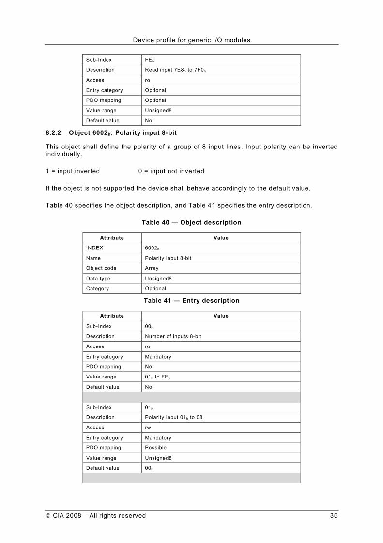
Sub-Index FEh
Description Read input 7E8h to 7F0h
Access ro
Entry category Optional
PDO mapping Optional
Value range Unsigned8
Default value No
8.2.2 Object 6002h: Polarity input 8-bit
This object shall define the polarity of a group of 8 input lines. Input polarity can be inverted individually.
1 = input inverted 0 = input not inverted
If the object is not supported the device shall behave accordingly to the default value.
Table 40 specifies the object description, and Table 41 specifies the entry description.
Table 40 — Object description
Attribute Value
INDEX 6002h
Name Polarity input 8-bit
Object code Array
Data type Unsigned8
Category Optional
Table 41 — Entry description
Attribute Value
Sub-Index 00h
Description Number of inputs 8-bit
Access ro
Entry category Mandatory
PDO mapping No
Value range 01h to FEh
Default value No
Sub-Index 01h
Description Polarity input 01h to 08h
Access rw
Entry category Mandatory
PDO mapping Possible
Value range Unsigned8
Default value 00h

Device profile for generic I/O modules
36 CiA 2008 – All rights reserved
Sub-Index 02h
Description Polarity input 09h to 10h
Access rw
Entry category Optional
PDO mapping Possible
Value range Unsigned8
Default value 00h
to
Sub-Index FEh
Description Polarity input 7E8h to 7F0h
Access rw
Entry category Optional
PDO mapping Optional
Value range Unsigned8
Default value 00h
8.2.3 Object 6003h: Filter constant input 8-bit
This object shall enable and disable an additional configurable filter constant. If the object is not supported, the device shall behave accordingly to the default value. The type of the filter constant and the configuration of the filter constant are manufacturer-specific.
1 = enabled 0 = disabled
Table 42 specifies the object description, and Table 43 specifies the entry description.
Table 42 — Object description
Attribute Value
INDEX 6003h
Name Filter constant input 8-bit
Object code Array
Data type Unsigned8
Category Optional
Table 43 — Entry description
Attribute Value
Sub-Index 00h
Description Number of inputs 8-bit
Access ro
Entry category Mandatory
PDO mapping No
Value range 01h to FEh
Default value No

Device profile for generic I/O modules
CiA 2008 – All rights reserved 37
Sub-Index 01h
Description Filter constant input 01h to 08h
Access rw
Entry category Mandatory
PDO mapping Optional
Value range Unsigned8
Default value 00h
Sub-Index 02h
Description Filter constant input 09h to 10h
Access rw
Entry category Optional
PDO mapping Optional
Value range Unsigned8
Default value 00h
to
Sub-Index FEh
Description Filter constant input 7E8h to 7F0h
Access rw
Entry category Optional
PDO mapping Optional
Value range Unsigned8
Default value 00h
8.2.4 Object 6005h: Global interrupt enable digital 8-bit
This object shall enable and disable globally the interrupt behavior without changing the interrupt masks. In event-driven mode the device transmits the input values depending on the interrupt masks in objects 6006h, 6007h, and 6008 (resp. 6050h to 6057h, 6060h to 6067h, 6070h to 6077h, or 6106h, 6107h, 6108h, or 6126h, 6127h, 6127h) and the PDO transmission type. If the object is not supported, the device shall behave accordingly to the default value.
TRUE = global interrupt enabled FALSE = global interrupt disabled
Table 44 specifies the object description, and Table 45 specifies the entry description.
Table 44 — Object description
Attribute Value
INDEX 6005h
Name Global interrupt enable digital 8-bit
Object code Variable
Data type Boolean
Category Optional

Device profile for generic I/O modules
38 CiA 2008 – All rights reserved
Table 45 — Entry description
Attribute Value
Sub-Index 00h
Access rw
PDO mapping No
Value range Boolean
Default value TRUE
8.2.5 Object 6006h: Interrupt mask any change 8-bit
This object determines, which input port lines shall activate an interrupt by positive or/and negative edge detection.
If the object is not supported the device shall behave accordingly to the default value.
Table 46 specifies the object description, Table 47 and specifies the entry description.
Table 46 — Object description
Attribute Value
INDEX 6006h
Name Interrupt mask any change 8-bit
Object code Array
Data type Unsigned8
Category Optional
Table 47 — Entry description
Attribute Value
Sub-Index 00h
Description Number of inputs 8-bit
Access ro
Entry category Mandatory
PDO mapping No
Value range 01h to FEh
Default value No
Sub-Index 01h
Description Interrupt any change 01h to 08h
Access rw
Entry category Mandatory
PDO mapping Optional
Value range Unsigned8
Default value FFh

Device profile for generic I/O modules
CiA 2008 – All rights reserved 39
Sub-Index 02h
Description Interrupt any change 09h to 10h
Access rw
Entry category Optional
PDO mapping Optional
Value range Unsigned8
Default value FFh
to
Sub-Index FEh
Description Interrupt any change 7E8h to 7F0h
Access rw
Entry category Optional
PDO mapping Optional
Value range Unsigned8
Default value FFh
8.2.6 Object 6007h: Interrupt mask low-to-high 8-bit
This object determines, which input port lines shall activate an interrupt by positive edge detection (logical 0 to 1). Done for groups of 8 lines. The values shall be in an ”OR” connection to the values of 6006h object (Interrupt mask any change 8-bit). If inputs are inverted by 6002h object (polarity input 8-bit), the positive logical edge shall correspond to negative physical edge.
1 = interrupt enabled 0 = interrupt disabled
Table 48 specifies the object description, and Table 49 specifies the entry description.
Table 48 — Object description
Attribute Value
INDEX 6007h
Name Interrupt mask low-to-high 8-bit
Object code Array
Data type Unsigned8
Category Optional
Table 49 — Entry description
Attribute Value
Sub-Index 00h
Description Number of inputs 8-bit
Access ro
Entry category Mandatory
PDO mapping No
Value range 01h to FEh
Default value No

Device profile for generic I/O modules
40 CiA 2008 – All rights reserved
Sub-Index 01h
Description Interrupt low-to-high 01h to 08h
Access rw
Entry category Mandatory
PDO mapping Optional
Value range Unsigned8
Default value 00h
Sub-Index 02h
Description Interrupt low-to-high 09h to 10h
Access rw
Entry category Optional
PDO mapping Optional
Value range Unsigned8
Default value 00h
to
Sub-Index FEh
Description Interrupt low-to-high 7E8h to 7F0h
Access rw
Entry category Optional
PDO mapping Optional
Value range Unsigned8
Default value 00h
8.2.7 Object 6008h: Interrupt mask high-to-low 8-bit
This object determines, which input port lines shall activate an interrupt by negative edge detection (logical 1 to 0). Done for groups of 8 lines. The values shall be in an ”OR” connection to the values of 6006h object (Interrupt mask any change 8-bit). If inputs are inverted by 6002h object (polarity input 8-bit), the negative logical edge shall correspond to positive physical edge.
1 = interrupt enabled 0 = interrupt disabled
Table 50 specifies the object description, and Table 51 specifies the entry description.
Table 50 — Object description
Attribute Value
INDEX 6008h
Name Interrupt mask high-to-low 8-bit
Object code Array
Data type Unsigned8
Category Optional

Device profile for generic I/O modules
CiA 2008 – All rights reserved 41
Table 51 — Entry description
Attribute Value
Sub-Index 00h
Description Number of inputs 8-bit
Access ro
Entry category Mandatory
PDO mapping No
Value range 01h to FEh
Default value No
Sub-Index 01h
Description Interrupt high-to-low 01h to 08h
Access rw
Entry category Mandatory
PDO mapping Optional
Value range Unsigned8
Default value 00h
Sub-Index 02h
Description Interrupt high-to-low 09h to 10h
Access rw
Entry category Optional
PDO mapping Optional
Value range Unsigned8
Default value 00h
to
Sub-Index FEh
Description Interrupt high-to-low 7F1h to 7F8h
Access rw
Entry category Optional
PDO mapping Optional
Value range Unsigned8
Default value 00h
8.2.8 Object 6020h to 6027h: Read input bit 1 to 128 to read input bit 897 to 1024
These objects shall read single input lines information. A maximum of 128 input lines is addressable at one index. The 6020h object shall address the input lines 1 to 128, the 6021h object shall address the input lines 129 to 256, etc.

Device profile for generic I/O modules
42 CiA 2008 – All rights reserved
Table 52 specifies the object description, and Table 53 specifies the entry description.
Table 52 — Object description
Attribute Value
INDEX 6020h
Name Read input bit 01h to 80h
Object code Array
Data type Boolean
Category Optional
Table 53 — Entry description
Attribute Value
Sub-Index 00h
Description Number of inputs 1-bit
Access ro
Entry category Mandatory
PDO mapping No
Value range 01h to 80h
Default value No
Sub-Index 01h
Description Read single input 01h
Access ro
Entry category Mandatory
PDO mapping Optional
Value range Boolean
Default value No
Sub-Index 02h
Description Read single input 02h
Access ro
Entry category Optional
PDO mapping Optional
Value range Boolean
Default value No
to
Sub-Index 80h
Description Read single input 80h
Access ro
Entry category Optional
PDO mapping Optional
Value range Boolean
Default value No

Device profile for generic I/O modules
CiA 2008 – All rights reserved 43
8.2.9 Object 6030h to 6037h: Polarity input bit 1 to 128 to polarity input bit 897 to 1024
These objects shall define the polarity of single input lines. A maximum of 128 input lines is addressable at one index. The 6030h object shall address the input lines 1 to 128, the 6031h object shall address the input lines 129 to 256, etc.
TRUE = input inverted FALSE = input not inverted
If these objects are not supported the device shall behave accordingly to the default value.
Table 54 specifies the object description, and Table 55 specifies the entry description.
Table 54 — Object description
Attribute Value
INDEX 6030h
Name Polarity input bit 01h to 80h
Object code Array
Data type Boolean
Category Optional
Table 55 — Entry description
Attribute Value
Sub-Index 00h
Description Number of inputs 1-bit
Access ro
Entry category Mandatory
PDO mapping No
Value range 01h to 80h
Default value No
Sub-Index 01h
Description Polarity input bit 01h
Access rw
Entry category Mandatory
PDO mapping Optional
Value range Boolean
Default value FALSE
Sub-Index 02h
Description Polarity input bit 02h
Access rw
Entry category Optional
PDO mapping Optional
Value range Boolean
Default value FALSE
to

Device profile for generic I/O modules
44 CiA 2008 – All rights reserved
Sub-Index 80h
Description Polarity input bit 80h
Access rw
Entry category Optional
PDO mapping Optional
Value range Boolean
Default value FALSE
8.2.10 Object 6038h to 603Fh: Filter constant input bit 1 to 128 to filter constant input bit 897 to 1024
These objects shall enable and disable an additional configurable filter constant. If these objects are not supported, the device shall behave accordingly to the default value. The type of the filter constant and the configuration of the filter constant are manufacturer-specific. The 6038h object shall address the input lines 1 to 128, the 6039h object shall address the input lines 129 to 256, etc.
TRUE = enabled FALSE = disable
Table 56 specifies the object description, and Table 57 specifies the entry description.
Table 56 — Object description
Attribute Value
INDEX 6038h
Name Filter constant input bit 01h to 80h
Object code Array
Data type Boolean
Category Optional
Table 57 — Entry description
Attribute Value
Sub-Index 00h
Description Number of inputs 1-bit
Access ro
Entry category Mandatory
PDO mapping No
Value range 01h to 80h
Default value No
Sub-Index 01h
Description Filter constant input bit 01h
Access rw
Entry category Mandatory
PDO mapping Optional
Value range Boolean
Default value FALSE

Device profile for generic I/O modules
CiA 2008 – All rights reserved 45
Sub-Index 02h
Description Filter constant input bit 02h
Access rw
Entry category Optional
PDO mapping Optional
Value range Boolean
Default value FALSE
to
Sub-Index 80h
Description Filter constant input bit 80h
Access rw
Entry category Optional
PDO mapping Optional
Value range Boolean
Default value FALSE
8.2.11 Object 6050h to 6057h: Interrupt mask input bit any change 1 to 128 to interrupt mask input bit any change 897 to 1024
These objects shall set interrupt masks for single input lines. A maximum of 128 bit inputs is addressable at one index. The 6050h object shall address the input lines 1 to 128, the 6051h object shall address the input lines 129 to 256, etc.
TRUE = interrupt enabled FALSE = interrupt disabled
If the object is not supported, the device shall behave accordingly to the default value.
Table 58 specifies the object description, and Table 59 specifies the entry description.
Table 58 — Object description
Attribute Value
INDEX 6050h
Name Interrupt mask input bit any change 01h to 80h
Object code Array
Data type Boolean
Category Optional
Table 59 — Entry description
Attribute Value
Sub-Index 00h
Description Number of inputs 1-bit
Access ro
Entry category Mandatory
PDO mapping No
Value range 01h to 80h
Default value No

Device profile for generic I/O modules
46 CiA 2008 – All rights reserved
Sub-Index 01h
Description Interrupt mask any change input bit 01h
Access rw
Entry category Mandatory
PDO mapping Optional
Value range Boolean
Default value TRUE
Sub-Index 02h
Description Interrupt mask any change input bit 02h
Access rw
Entry category Optional
PDO mapping Optional
Value range Boolean
Default value TRUE
to
Sub-Index 80h
Description Interrupt mask any change input bit 80h
Access rw
Entry category Optional
PDO mapping Optional
Value range Boolean
Default value TRUE
8.2.12 Object 6060h to 6067h: Interrupt mask input low-to-high bit 1 to 128 to interrupt mask input low-to-high bit 897 to 1024
These objects shall set interrupt masks for a single input line. A maximum of 128 bit inputs is addressable at one index. The 6060h object shall address the input lines 1 to 128, the 6061h object shall address the input lines 129 to 256, etc. The values shall be in an ”OR” connection to the values of 6050h to 6057h objects (interrupt mask any change). If inputs are inverted by 6030h to 6037h objects (polarity input), the positive logical edge shall correspond to negative physical edge.
TRUE = interrupt enabled FALSE = interrupt disabled
If the object is not supported, the device shall behave accordingly to the default value.
Table 60 specifies the object description, and Table 61 specifies the entry description.
Table 60 — Object description
Attribute Value
INDEX 6060h
Name Interrupt mask input low-to-high bit 01h to 80h
Object code Array
Data type Boolean
Category Optional

Device profile for generic I/O modules
CiA 2008 – All rights reserved 47
Table 61 — Entry description
Attribute Value
Sub-Index 00h
Description Number of inputs 1-bit
Access rw
Entry category Mandatory
PDO mapping No
Value range 01h to 80h
Default value No
Sub-Index 01h
Description Interrupt mask low-to-high input 01h
Access rw
Entry category Mandatory
PDO mapping Optional
Value range Boolean
Default value FALSE
Sub-Index 02h
Description Interrupt mask low-to-high input 02h
Access rw
Entry category Optional
PDO mapping Optional
Value range Boolean
Default value FALSE
to
Sub-Index 80h
Description Interrupt mask low-to-high input 80h
Access rw
Entry category Optional
PDO mapping Optional
Value range Boolean
Default value FALSE
8.2.13 Object 6070h to 6077h: Interrupt mask input high-to-low bit 1 to 128 to interrupt mask input high-to-low bit 897 to 1024
These objects shall set interrupt masks for single input lines. A maximum of 128 bit inputs is addressable at one index. The 6070h object shall address the input lines 1 to 128, the 6071h object shall address the input lines 129 to 256, etc. The values shall be in an ”OR” connection to the values of 6050h to 6057h objects (interrupt mask any change). If inputs are inverted by 6030h to 6037h objects (polarity input), the negative logical edge shall correspond to positive physical edge.
TRUE = interrupt enabled FALSE = interrupt disabled
If the object is not supported, the device shall behave accordingly to the default value.

Device profile for generic I/O modules
48 CiA 2008 – All rights reserved
Table 62 specifies the object description, and Table 63 specifies the entry description.
Table 62 — Object description
Attribute Value
INDEX 6070h
Name Interrupt mask input high-to-low bit 01h to 80h
Object code Array
Data type Boolean
Category Optional
Table 63 — Entry description
Attribute Value
Sub-Index 00h
Description Number of inputs 1-bit
Access rw
Entry category Mandatory
PDO mapping No
Value range 01h to 80h
Default value No
Sub-Index 01h
Description Interrupt mask high-to-low input 01h
Access rw
Entry category Mandatory
PDO mapping Optional
Value range Boolean
Default value FALSE
Sub-Index 02h
Description Interrupt mask high-to-low input 02h
Access rw
Entry category Optional
PDO mapping Optional
Value range Boolean
Default value FALSE
to
Sub-Index 80h
Description Interrupt mask high-to-low input 80h
Access rw
Entry category Optional
PDO mapping Optional
Value range Boolean
Default value FALSE

Device profile for generic I/O modules
CiA 2008 – All rights reserved 49
8.2.14 Object 6100h: Read input 16-bit
The object shall read a group of 16 input lines as 16-bit information. A maximum of 254 x 16-bit words is addressable (4064 inputs).
Table 64 specifies the object description, and Table 65 specifies the entry description.
Table 64 — Object description
Attribute Value
INDEX 6100h
Name Read input 16-bit
Object code Array
Data type Unsigned16
Category Optional
Table 65 — Entry description
Attribute Value
Sub-Index 00h
Description Number of inputs 16-bit
Access ro
Entry category Mandatory
PDO mapping No
Value range 01h to FEh
Default value No
Sub-Index 01h
Description Read input 01h to 10h
Access ro
Entry category Mandatory
PDO mapping Optional
Value range Unsigned16
Default value No
Sub-Index 02h
Description Read input 11h to 20h
Access ro
Entry category Optional
PDO mapping Optional
Value range Unsigned16
Default value No
to

Device profile for generic I/O modules
50 CiA 2008 – All rights reserved
Sub-Index FEh
Description Read input FD0h to FE0h
Access ro
Entry category Optional
PDO mapping Optional
Value range Unsigned16
Default value No
8.2.15 Object 6102h: Polarity input 16-bit
This object shall define the polarity for a group of 16 input lines. Inputs can be inverted individually.
1 = input inverted 0 = input not inverted
If the object is not supported the device shall behave accordingly to the default value.
Table 66 specifies the object description, and Table 67 specifies the entry description.
Table 66 — Object description
Attribute Value
INDEX 6102h
Name Polarity input 16-bit
Object code Array
Data type Unsigned16
Category Optional
Table 67 — Entry description
Attribute Value
Sub-Index 00h
Description Number of inputs 16-bit
Access ro
Entry category Mandatory
PDO mapping No
Value range 01h to FEh
Default value No
Sub-Index 01h
Description Polarity input 01h to 10h
Access rw
Entry category Mandatory
PDO mapping Optional
Value range Unsigned16
Default value 0000h

Device profile for generic I/O modules
CiA 2008 – All rights reserved 51
Sub-Index 02h
Description Polarity input 11h to 20h
Access rw
Entry category Optional
PDO mapping Optional
Value range Unsigned16
Default value 0000h
to
Sub-Index FEh
Description Polarity input FD1h to FF0h
Access rw
Entry category Optional
PDO mapping Optional
Value range Unsigned16
Default value 0000h
8.2.16 Object 6103h: Filter constant input 16-bit
This object shall enable and disable an additional configurable filter constant. If the object is not supported, the device shall behave accordingly to the default value. The type of the filter constant and the configuration of the filter constant are manufacturer-specific.
1 = enabled 0 = disabled
Table 68 specifies the object description, and Table 69 specifies the entry description.
Table 68 — Object description
Attribute Value
INDEX 6103h
Name Filter constant input 16-bit
Object code Array
Data type Unsigned16
Category Optional
Table 69 — Entry description
Attribute Value
Sub-Index 00h
Description Number of inputs 16-bit
Access ro
Entry category Mandatory
PDO mapping No
Value range 01h to FEh
Default value No

Device profile for generic I/O modules
52 CiA 2008 – All rights reserved
Sub-Index 01h
Description Filter constant input 01h to 10h
Access rw
Entry category Mandatory
PDO mapping Optional
Value range Unsigned16
Default value 0000h
Sub-Index 02h
Description Filter constant input 11h to 20h
Access rw
Entry category Optional
PDO mapping Optional
Value range Unsigned16
Default value 0000h
to
Sub-Index FEh
Description Filter constant input FD1h to FE0h
Access rw
Entry category Optional
PDO mapping Optional
Value range Unsigned16
Default value 0000h
8.2.17 Object 6106h: Interrupt mask input any change 16-bit
This object determines, which input port lines shall activate an interrupt. Done for groups of 16 lines and for any change of a digital input line.
1 = interrupt enabled 0 = interrupt disabled
If the object is not supported, the device shall behave accordingly to the default value.
Table 70 specifies the object description, and Table 71 specifies the entry description.
Table 70 — Object description
Attribute Value
INDEX 6106h
Name Interrupt mask input any change 16-bit
Object code Array
Data type Unsigned16
Category Optional

Device profile for generic I/O modules
CiA 2008 – All rights reserved 53
Table 71 — Entry description
Attribute Value
Sub-Index 00h
Description Number of inputs 16-bit
Access ro
Entry category Mandatory
PDO mapping No
Value range 01h to FEh
Default value No
Sub-Index 01h
Description Interrupt any change inputs 01h to 10h
Access rw
Entry category Mandatory
PDO mapping Optional
Value range Unsigned16
Default value FFFFh
Sub-Index 02h
Description Interrupt any change inputs 11h to 20h
Access rw
Entry category Optional
PDO mapping Optional
Value range Unsigned16
Default value FFFFh
to
Sub-Index FEh
Description Interrupt any change inputs FD1h to FE0h
Access rw
Entry category Optional
PDO mapping Optional
Value range Unsigned16
Default value FFFFh
8.2.18 Object 6107h: Interrupt mask input low-to-high 16-bit
This object determines, which input port lines shall activate an interrupt. Done for groups of 16 lines and for a change from low-to-high of a digital input line. The values shall be in an ”OR” connection to the values of 6106h object (interrupt mask any change 16-bit). If inputs are inverted by 6102h object (polarity input 16-bit), the positive logical edge shall correspond to negative physical edge.
1 = interrupt enabled 0 = interrupt disabled
If the object is not supported, the device shall behave accordingly to the default value.

Device profile for generic I/O modules
54 CiA 2008 – All rights reserved
Table 72 specifies the object description, and Table 73 specifies the entry description.
Table 72 — Object description
Attribute Value
INDEX 6107h
Name Interrupt mask input low-to-high 16-bit
Object code Array
Data type Unsigned16
Category Optional
Table 73 — Entry description
Attribute Value
Sub-Index 00h
Description Number of inputs 16-bit
Access ro
Entry category Mandatory
PDO mapping No
Value range 01h to FEh
Default value No
Sub-Index 01h
Description Interrupt low-to-high inputs 01h to 10h
Access rw
Entry category Mandatory
PDO mapping Optional
Value range Unsigned16
Default value 0000h
Sub-Index 02h
Description Interrupt low-to-high inputs 11h to 20h
Access rw
Entry category Optional
PDO mapping Optional
Value range Unsigned16
Default value 0000h
to
Sub-Index FEh
Description Interrupt low-to-high inputs FD1h to FE0h
Access rw
Entry category Optional
PDO mapping Optional
Value range Unsigned16
Default value 0000h

Device profile for generic I/O modules
CiA 2008 – All rights reserved 55
8.2.19 Object 6108h: Interrupt mask input high-to-low 16-bit
This object determines, which input port lines shall activate an interrupt. Done for groups of 16 lines and for a change from high-to-low of a digital input line. The values shall be in an ”OR” connection to the values of 6106h object (interrupt mask any change 16-bit). If inputs are inverted by 6102h object (polarity input 16-bit), the negative logical edge shall correspond to positive physical edge.
1 = interrupt enabled 0 = interrupt disabled
If the object is not supported, the device shall behave accordingly to the default value.
Table 74 specifies the object description, and Table 75 specifies the entry description
Table 74 — Object description
Attribute Value
INDEX 6108h
Name Interrupt mask input high-to-low 16-bit
Object code Array
Data type Unsigned16
Category Optional
Table 75 — Entry description
Attribute Value
Sub-Index 00h
Description Number of inputs 16-bit
Access ro
Entry category Mandatory
PDO mapping No
Value range 01h to FEh
Default value No
Sub-Index 01h
Description Interrupt high-to-low inputs 01h to 10h
Access rw
Entry category Mandatory
PDO mapping Optional
Value range Unsigned16
Default value 0000h
Sub-Index 02h
Description Interrupt high-to-low inputs 11h to 20h
Access rw
Entry category Optional
PDO mapping Optional
Value range Unsigned16
Default value 0000h
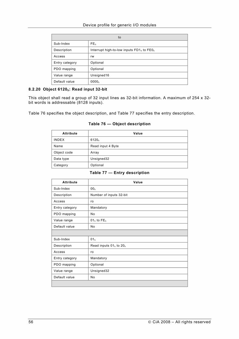
Device profile for generic I/O modules
56 CiA 2008 – All rights reserved
to
Sub-Index FEh
Description Interrupt high-to-low inputs FD1h to FE0h
Access rw
Entry category Optional
PDO mapping Optional
Value range Unsigned16
Default value 0000h
8.2.20 Object 6120h: Read input 32-bit
This object shall read a group of 32 input lines as 32-bit information. A maximum of 254 x 32-bit words is addressable (8128 inputs).
Table 76 specifies the object description, and Table 77 specifies the entry description.
Table 76 — Object description
Attribute Value
INDEX 6120h
Name Read input 4 Byte
Object code Array
Data type Unsigned32
Category Optional
Table 77 — Entry description
Attribute Value
Sub-Index 00h
Description Number of inputs 32-bit
Access ro
Entry category Mandatory
PDO mapping No
Value range 01h to FEh
Default value No
Sub-Index 01h
Description Read inputs 01h to 20h
Access ro
Entry category Mandatory
PDO mapping Optional
Value range Unsigned32
Default value No

Device profile for generic I/O modules
CiA 2008 – All rights reserved 57
Sub-Index 02h
Description Read inputs 21h to 40h
Access ro
Entry category Optional
PDO mapping Optional
Value range Unsigned32
Default value No
to
Sub-Index FEh
Description Read inputs 1FA0h to 1FC0h
Access ro
Entry category Optional
PDO mapping Optional
Value range Unsigned32
Default value No
8.2.21 Object 6122h: Polarity input 32-bit
This object shall define the polarity for a group of 32 input lines. Inputs can be inverted individually.
1 = input inverted 0 = input not inverted
If the object is not supported the device shall behave accordingly to the default value.
Table 78 specifies the object description, and Table 79 specifies the entry description.
Table 78 — Object description
Attribute Value
INDEX 6122h
Name Polarity input 32-bit
Object code Array
Data type Unsigned32
Category Optional
Table 79 — Entry description
Attribute Value
Sub-Index 00h
Description Number of inputs 32-bit
Access ro
PDO mapping No
Value range 01h to FEh
Default value 0000 0000h

Device profile for generic I/O modules
58 CiA 2008 – All rights reserved
Sub-Index 01h
Description Polarity inputs 01h to 20h
Access rw
Entry category Mandatory
PDO mapping No
Value range Unsigned32
Default value 0000 0000h
Sub-Index 02h
Description Polarity inputs 21h to 40h
Access rw
Entry category Optional
PDO mapping No
Value range Unsigned32
Default value 0000 0000h
to
Sub-Index FEh
Description Polarity inputs 1FA0h to 1FC0h
Access rw
Entry category Optional
PDO mapping Optional
Value range Unsigned32
Default value 0000 0000h
8.2.22 Object 6123h: Filter constant input 32-bit
This object shall enable and disable an additional configurable filter constant. If the object is not supported, the device shall behave accordingly to the default value. The type of the filter constant and the configuration of the filter constant are manufacturer-specific.
1 = enabled 0 = disabled
Table 80 specifies the object description, and Table 81 specifies the entry description.
Table 80 — Object description
Attribute Value
INDEX 6123h
Name Filter constant input 32-bit
Object code Array
Data type Unsigned32
Category Optional

Device profile for generic I/O modules
CiA 2008 – All rights reserved 59
Table 81 — Entry description
Attribute Value
Sub-Index 00h
Description Number of inputs 32-bit
Access ro
Entry category Mandatory
PDO mapping No
Value range 01h to FEh
Default value No
Sub-Index 01h
Description Filter constant inputs 01h to 20h
Access rw
Entry category Mandatory
PDO mapping Optional
Value range Unsigned32
Default value 0000 0000h
Sub-Index 02h
Description Filter constant inputs 21h to 40h
Access rw
Entry category Optional
PDO mapping Optional
Value range Unsigned32
Default value 0000 0000h
to
Sub-Index FEh
Description Filter constant inputs 1FA1h to 1FC0h
Access rw
Entry category Optional
PDO mapping Optional
Value range Unsigned32
Default value 0000 0000h
8.2.23 Object 6126h: Interrupt mask input any change 32-bit
This object determines which input port lines shall activate an interrupt. Done for groups of 32 lines and for any change of a digital input line.
1 = interrupt enabled 0 = interrupt disabled
If the object is not supported, the device shall behave accordingly to the default value.

Device profile for generic I/O modules
60 CiA 2008 – All rights reserved
Table 82 specifies the object description, and Table 83 specifies the entry description.
Table 82 — Object description
Attribute Value
INDEX 6126h
Name Interrupt mask input any change 32-bit
Object code Array
Data type Unsigned32
Category Optional
Table 83 — Entry description
Attribute Value
Sub-Index 00h
Description Number of inputs 32-bit
Access ro
Entry category Mandatory
PDO mapping No
Value range 01h to FEh
Default value No
Sub-Index 01h
Description Interrupt any change input 01h to 20h
Access rw
Entry category Mandatory
PDO mapping Optional
Value range Unsigned32
Default value FFFF FFFFh
Sub-Index 02h
Description Interrupt any change input 21h to 40h
Access rw
Entry category Optional
PDO mapping Optional
Value range Unsigned32
Default value FFFF FFFFh
to
Sub-Index FEh
Description Interrupt any change input 1FA1h to 1FC0h
Access rw
Entry category Optional
PDO mapping Optional
Value range Unsigned32
Default value FFFF FFFFh

Device profile for generic I/O modules
CiA 2008 – All rights reserved 61
8.2.24 Object 6127h: Interrupt mask input low-to-high 32-bit
This object determines, which input port lines shall activate an interrupt. Done for groups of 32 lines and for a change from low-to-high of a digital input line. The values shall be in an ”OR” connection to the values of 6126h object (interrupt mask any change 32-bit). If inputs are inverted by 6122h object (polarity input 32-bit), the positive logical edge shall correspond to negative physical edge.
1 = interrupt enabled 0 = interrupt disabled
If the object is not supported, the device shall behave accordingly to the default value.
Table 84 specifies the object description, and Table 85 specifies the entry description.
Table 84 — Object description
Attribute Value
INDEX 6127h
Name Interrupt mask input low-to-high 32-bit
Object code Array
Data type Unsigned32
Category Optional
Table 85 — Entry description
Attribute Value
Sub-Index 00h
Description Number of inputs 32-bit
Access ro
Entry category Mandatory
PDO mapping No
Value range 01h to FEh
Default value No
Sub-Index 01h
Description Interrupt low-to-high input 01h to 20h
Access rw
Entry category Mandatory
PDO mapping Optional
Value range Unsigned32
Default value 0000 0000h
Sub-Index 02h
Description Interrupt low-to-high input 21h to 40h
Access rw
Entry category Optional
PDO mapping Optional
Value range Unsigned32
Default value 0000 0000h

Device profile for generic I/O modules
62 CiA 2008 – All rights reserved
to
Sub-Index FEh
Description Interrupt low-to-high input 1FA1h to 1FC0h
Access rw
Entry category Optional
PDO mapping Optional
Value range Unsigned32
Default value 0000 0000h
8.2.25 Object 6128h: Interrupt mask input high-to-low 32-bit
This object determines, which input port lines shall activate an interrupt. Done for groups of 32 lines and for a change from high-to-low of a digital input line. The values shall be in an ”OR” connection to the values of 6126h object (interrupt mask any change 32-bit). If inputs are inverted by 6122h object (polarity input 32-bit), the negative logical edge shall correspond to positive physical edge.
1 = interrupt enabled 0 = interrupt disabled
If the object is not supported, the device shall behave accordingly to the default value.
Table 86 specifies the object description, and Table 87 specifies the entry description.
Table 86 — Object description
Attribute Value
INDEX 6128h
Name Interrupt mask input high-to-low 32-bit
Object code Array
Data type Unsigned32
Category Optional
Table 87 — Entry description
Attribute Value
Sub-Index 00h
Description Number of inputs 32-bit
Access ro
Entry category Mandatory
PDO mapping No
Value range 01h to FEh
Default value No
Sub-Index 01h
Description Interrupt high-to-low input 01h to 20h
Access rw
Entry category Mandatory
PDO mapping Optional
Value range Unsigned32
Default value 0000 0000h
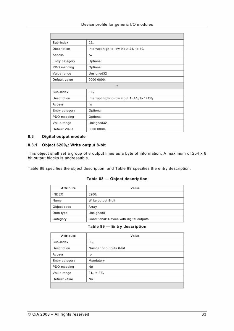
Device profile for generic I/O modules
CiA 2008 – All rights reserved 63
Sub-Index 02h
Description Interrupt high-to-low input 21h to 40h
Access rw
Entry category Optional
PDO mapping Optional
Value range Unsigned32
Default value 0000 0000h
to
Sub-Index FEh
Description Interrupt high-to-low input 1FA1h to 1FC0h
Access rw
Entry category Optional
PDO mapping Optional
Value range Unisgned32
Default Vlaue 0000 0000h
8.3 Digital output module
8.3.1 Object 6200h: Write output 8-bit
This object shall set a group of 8 output lines as a byte of information. A maximum of 254 x 8 bit output blocks is addressable.
Table 88 specifies the object description, and Table 89 specifies the entry description.
Table 88 — Object description
Attribute Value
INDEX 6200h
Name Write output 8-bit
Object code Array
Data type Unsigned8
Category Conditional: Device with digital outputs
Table 89 — Entry description
Attribute Value
Sub-Index 00h
Description Number of outputs 8-bit
Access ro
Entry category Mandatory
PDO mapping No
Value range 01h to FEh
Default value No

Device profile for generic I/O modules
64 CiA 2008 – All rights reserved
Sub-Index 01h
Description Write output 01h to 08h
Access rw
Entry category Mandatory
PDO mapping Default
Value range Unsigned8
Default value 00h
Sub-Index 02h
Description Write output 09h to 10h
Access rw
Entry category Optional
PDO mapping Default
Value range Unsigned8
Default value 00h
to
Sub-Index 08h
Description Write output 39h to 40h
Access rw
Entry category Optional
PDO mapping Default
Value range Unsigned8
Default value 00h
Sub-Index 09h
Description Write output 41h to 48h
Access rw
Entry category Optional
PDO mapping Optional
Value range Unsigned8
Default value 00h
to
Sub-Index FEh
Description Write output 7E9h to 7F0h
Access rw
Entry category Optional
PDO mapping Optional
Value range Unsigned8
Default value 00h
8.3.2 Object 6202h: Change polarity output 8-bit
This object shall define the polarity of a group of 8 output lines. Output polarity can be inverted individually.
1 = output inverted 0 = output not inverted

Device profile for generic I/O modules
CiA 2008 – All rights reserved 65
If the object is not supported, the device shall behave accordingly to the default value.
Table 90 specifies the object description, and Table 91 specifies the entry description.
Table 90 — Object description
Attribute Value
INDEX 6202h
Name Change polarity output 8-bit
Object code Array
Data type Unsigned8
Category Optional
Table 91 — Entry description
Attribute Value
Sub-Index 00h
Description Number of outputs 8-bit
Access ro
Entry category Mandatory
PDO mapping No
Value range 01h to FEh
Default value No
Sub-Index 01h
Description Change polarity output 01h to 08h
Access rw
Entry category Mandatory
PDO mapping Optional
Value range Unsigned8
Default value 00h
Sub-Index 02h
Description Change polarity output 09h to 10h
Access rw
Entry category Optional
PDO mapping Optional
Value range Unsigned8
Default value 00h
to
Sub-Index FEh
Description Change polarity output 7E9h to 7F0h
Access rw
Entry category Optional
PDO mapping Optional
Value range Unsigned8
Default value 00h

Device profile for generic I/O modules
66 CiA 2008 – All rights reserved
8.3.3 Object 6206h: Error mode output 8-bit
This object indicates, whether an output is set to a pre-defined error value (see 6207h object) in case of an internal device failure or a 'Stop Remote Node' indication.
1 = output value shall take the pre-defined condition specified in 6207h object 0 = output value shall be kept if an error occurs
If the object is not supported, the device shall behave accordingly to the default value.
Table 92 specifies the object description, and Table 93 specifies the entry description.
Table 92 — Object description
Attribute Value
INDEX 6206h
Name Error mode output 8-bit
Object code Array
Data type Unsigned8
Category Optional
Table 93 — Entry description
Attribute Value
Sub-Index 00h
Description Number of outputs 8-bit
Access ro
Entry category Mandatory
PDO mapping No
Value range 01h to FEh
Default value No
Sub-Index 01h
Description Error mode output 01h to 08h
Access rw
Entry category Mandatory
PDO mapping Optional
Value range Unsigned8
Default value FFh
Sub-Index 02h
Description Error mode output 09h to 10h
Access rw
Entry category Optional
PDO mapping Optional
Value range Unsigned8
Default value FFh
to

Device profile for generic I/O modules
CiA 2008 – All rights reserved 67
Sub-Index FEh
Description Error mode output 7E9h to 7F0h
Access rw
Entry category Optional
PDO mapping Optional
Value range Unsigned8
Default value FFh
8.3.4 Object 6207h: Error value output 8-bit
On condition that the corresponding Error mode is active, device failures (see chapter 5.2) shall set the outputs to the value configured by this object.
0 = output shall be set to ‘0’ in case of fault, if 6206h object is enabled 1 = output shall be set to ‘1’ in case of fault, if 6206h object is enabled
If the object is not supported, the device shall behave accordingly to the default value.
Table 94 specifies the object description, and Table 95 specifies the entry description.
Table 94 — Object description
Attribute Value
INDEX 6207h
Name Error value output 8-bit
Object code Array
Data type Unsigned8
Category Optional
Table 95 — Entry description
Attribute Value
Sub-Index 00h
Description Number of outputs 8-bit
Access ro
Entry category Mandatory
PDO mapping No
Value range 01h to FEh
Default value No
Sub-Index 01h
Description Error value output 01h to 08h
Access rw
Entry category Mandatory
PDO mapping Optional
Value range Unsigned8
Default value 00h
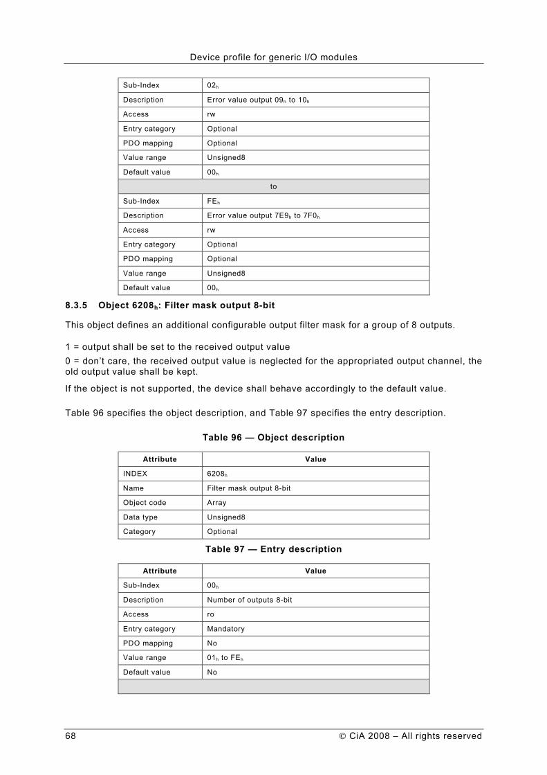
Device profile for generic I/O modules
68 CiA 2008 – All rights reserved
Sub-Index 02h
Description Error value output 09h to 10h
Access rw
Entry category Optional
PDO mapping Optional
Value range Unsigned8
Default value 00h
to
Sub-Index FEh
Description Error value output 7E9h to 7F0h
Access rw
Entry category Optional
PDO mapping Optional
Value range Unsigned8
Default value 00h
8.3.5 Object 6208h: Filter mask output 8-bit
This object defines an additional configurable output filter mask for a group of 8 outputs.
1 = output shall be set to the received output value 0 = don’t care, the received output value is neglected for the appropriated output channel, the old output value shall be kept.
If the object is not supported, the device shall behave accordingly to the default value.
Table 96 specifies the object description, and Table 97 specifies the entry description.
Table 96 — Object description
Attribute Value
INDEX 6208h
Name Filter mask output 8-bit
Object code Array
Data type Unsigned8
Category Optional
Table 97 — Entry description
Attribute Value
Sub-Index 00h
Description Number of outputs 8-bit
Access ro
Entry category Mandatory
PDO mapping No
Value range 01h to FEh
Default value No

Device profile for generic I/O modules
CiA 2008 – All rights reserved 69
Sub-Index 01h
Description Filter mask output 01h to 08h
Access rw
Entry category Mandatory
PDO mapping Optional
Value range Unsigned8
Default value FFh
Sub-Index 02h
Description Filter mask output 09h to 10h
Access rw
Entry category Optional
PDO mapping Optional
Value range Unsigned8
Default value FFh
to
Sub-Index FEh
Description Filter mask output 7E9h to 7F0h
Access rw
Entry category Optional
PDO mapping Optional
Value range Unsigned8
Default value FFh
8.3.6 Object 6220h to 6227h: Write output bit 1 to 128 to write output bit 897 to 1024
These objects shall set single output lines information. A maximum of 128 outputs is addressable at one index. The 6220h object shall address output lines 1 to 128, the 6221h object shall address output lines 129 to 256, etc.
Table 98 specifies the object description, and Table 99 specifies the entry description.
Table 98 — Object description
Attribute Value
Name Write output bit 01h to 80h
Object code Array
Data type Boolean
Category Optional
Table 99 — Entry description
Attribute Value
Description Number of outputs 1-bit
Access ro
Entry category Mandatory
PDO mapping No
Value range 01h to 80h
Default value No

Device profile for generic I/O modules
70 CiA 2008 – All rights reserved
Sub-Index 01h
Description Write output 01h
Access rw
Entry category Mandatory
PDO mapping Optional
Value range Boolean
Default value FALSE
Sub-Index 02h
Description Write output 02h
Access rw
Entry category Optional
PDO mapping Optional
Value range Boolean
Default value FALSE
to
Sub-Index 80h
Description Write output 80h
Access rw
Entry category Optional
PDO mapping Optional
Value range Boolean
Default value FALSE
8.3.7 Object 6240h to 6247h: Change polarity output bit 1 to 128 to change polarity output bit 897 to 1024
These objects shall set the polarity of single output lines. A maximum of 128 outputs is addressable at one index. The 6240h object shall address output lines 1 to 128, the 6241h object shall address output lines 129 to 256, etc.
TRUE = output inverted FALSE = output not inverted
If these objects are not supported the device shall behave accordingly to the default value.
Table 100 specifies the object description, and Table 101 specifies the entry description.
Table 100 — Object description
Attribute Value
INDEX 6240h
Name Change polarity output bit 01h to 80h
Object code Array
Data type Boolean
Category Optional

Device profile for generic I/O modules
CiA 2008 – All rights reserved 71
Table 101 — Entry description
Attribute Value
Sub-Index 00h
Description Number of outputs 1-bit
Access ro
Entry category Mandatory
PDO mapping No
Value range 01h to 80h
Default value No
Sub-Inde 01h
Description Change polarity output 01h
Access rw
Entry category Mandatory
PDO mapping Optional
Value range Boolean
Default value FALSE
Sub-Index 02h
Description Change polarity output 02h
Access rw
Entry category Optional
PDO mapping Optional
Value range Boolean
Default value FALSE
to
Sub-Index 80h
Description Change polarity output 80h
Access rw
Entry category Optional
PDO mapping Optional
Value range Boolean
Default value FALSE
8.3.8 Object 6250h to 6257h: Error mode output lines 1 to 128 to error mode output lines 897 to 1024
These objects indicate, whether an output is set to a pre-defined error value (see 6260h to 6267h objects) in case of an internal device failure a 'Stop remote node' indication. A maximum of 128 outputs is addressable at one index. The 6250h object shall address output lines 1 to 128, the 6251h object shall address output lines 129 to 256, etc.
TRUE = output value shall take the pre-defined condition as specified in 6260h to 6267h objects FALSE = output value shall be kept if an error occurs
If the object is not supported, the device shall behave accordingly to the default value.

Device profile for generic I/O modules
72 CiA 2008 – All rights reserved
Table 102 specifies the object description, and Table 103 specifies the entry description.
Table 102 — Object description
Attribute Value
INDEX 6250h
Name Error mode output lines 01h to 80h
Object code Array
Data type Boolean
Category Optional
Table 103 — Entry description
Attribute Value
Sub-Index 00h
Description Number of outputs 1-bit
Access ro
Entry category Mandatory
PDO mapping No
Value range 01h to 80h
Default value No
Sub-Index 01h
Description Error mode output 01h
Access rw
Entry category Mandatory
PDO mapping Optional
Value range Boolean
Default value TRUE
Sub-Index 02h
Description Error mode output 02h
Access rw
Entry category Optional
PDO mapping Optional
Value range Boolean
Default value TRUE
to
Sub-Index 80h
Description Error mode output 80h
Access rw
Entry category Optional
PDO mapping Optional
Value range Boolean
Default value TRUE

Device profile for generic I/O modules
CiA 2008 – All rights reserved 73
8.3.9 Object 6260h to 6267h: Error value output bit 1 to 128 to error value output bit 897 to 1024
On condition that the corresponding error mode is active, device failures (see chapter 5.2) shall set the outputs to the value configured by this object. A maximum of 128 outputs is addressable at one index. The 6260h object shall address output lines 1 to 128, the 6261h object shall address output lines 129 to 256, etc.
FALSE = output shall be set to ‘0’ in case of fault, if the corresponding object (6250h to 6257h) is enabled TRUE = output shall be set to ‘1’ in case of fault, if the corresponding object (6250h to 6257h) is enabled
If the object is not supported, the device shall behave accordingly to the default value.
Table 104 specifies the object description, and Table 105 specifies the entry description.
Table 104 — Object description
Attribute Value
INDEX 6260h
Name Error value output bit 01h to 80h
Object code Array
Data type Boolean
Categrory Optional
Table 105 — Entry description
Attribute Value
Sub-Index 00h
Description Number of outputs 1-bit
Access ro
Entry category Mandatory
PDO mapping No
Value range 01h to 80h
Default value No
Default value No
Sub-Index 01h
Description Error value output 01h
Access rw
Entry category Mandatory
PDO mapping Optional
Value range Boolean
Default value FALSE

Device profile for generic I/O modules
74 CiA 2008 – All rights reserved
Sub-Index 02h
Description Error value output 02h
Access rw
Entry category Optional
PDO mapping Optional
Value range Boolean
Default value FALSE
to
Sub-Index 80h
Description Error value output 80h
Access rw
Entry category Optional
PDO mapping Optional
Value range Boolean
Default value FALSE
8.3.10 Object 6270h to 6277h: Filter mask output bit 1 to 128 to filter mask output bit 897 to 1024
This object defines an additional configurable output filter mask for a single output.
TRUE = output shall set to the received output value FALSE = don’t care the received output value is neglected for the appropriated output channel, the old output value shall be kept
A maximum of 128 outputs is addressable at one index. The 6270h object shall address output lines 1 to 128, the 6271h object shall address output lines 129 to 256, etc.
If the object is not supported, the device shall behave accordingly to the default value.
Table 106 specifies the object description, and Table 107 specifies the entry description.
Table 106 — Object description
Attribute Value
INDEX 6270h
Name Filter mask output bit 01h to 80h
Object code Array
Data type Boolean
Category Optional
Table 107 — Entry description
Attribute Value
Sub-Index 00h
Description Number of outputs 1-bit
Access ro
Entry category Mandatory
PDO mapping No
Value range 01h to 80h
Default value No

Device profile for generic I/O modules
CiA 2008 – All rights reserved 75
Sub-Index 01h
Description Filter mask output 01h
Access rw
Entry category Mandatory
PDO mapping Optional
Value range Boolean
Default value TRUE
Sub-Index 02h
Description Filter mask output 02h
Data type Boolean
Access rw
Entry category Optional
PDO mapping Optional
Value range Boolean
Default value TRUE
to
Sub-Index 80h
Description Filter mask output 80h
Data type Boolean
Access rw
Entry category Optional
PDO mapping Optional
Value range Boolean
Default value TRUE
8.3.11 Object 6300h: Write output 16-bit
This object shall set a group of 16 output lines as 2-byte information. A maximum of 255 x 16-bit words is addressable (4080 outputs).
Table 108 specifies the object description, and Table 109 specifies the entry description.
Table 108 — Object description
Attribute Value
INDEX 6300h
Name Write output 16-bit
Object code Array
Data type Unsigned16
Category Optional
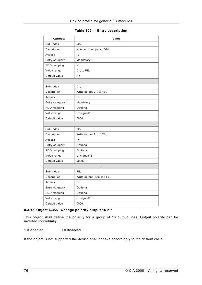
Device profile for generic I/O modules
76 CiA 2008 – All rights reserved
Table 109 — Entry description
Attribute Value
Sub-Index 00h
Description Number of outputs 16-bit
Access ro
Entry category Mandatory
PDO mapping No
Value range 01h to FEh
Default value No
Sub-Index 01h
Description Write output 01h to 10h
Access rw
Entry category Mandatory
PDO mapping Optional
Value range Unsigned16
Default value 0000h
Sub-Index 02h
Description Write output 11h to 20h
Access rw
Entry category Optional
PDO mapping Optional
Value range Unsigned16
Default value 0000h
to
Sub-Index FEh
Description Write output FE0h to FF0h
Access rw
Entry category Optional
PDO mapping Optional
Value range Unsigned16
Default value 0000h
8.3.12 Object 6302h: Change polarity output 16-bit
This object shall define the polarity for a group of 16 output lines. Output polarity can be inverted individually.
1 = enabled 0 = disabled
If the object is not supported the device shall behave accordingly to the default value.
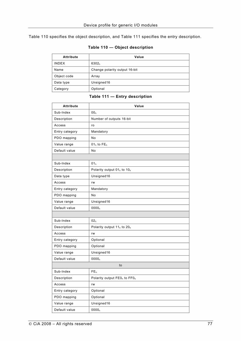
Device profile for generic I/O modules
CiA 2008 – All rights reserved 77
Table 110 specifies the object description, and Table 111 specifies the entry description.
Table 110 — Object description
Attribute Value
INDEX 6302h
Name Change polarity output 16-bit
Object code Array
Data type Unsigned16
Category Optional
Table 111 — Entry description
Attribute Value
Sub-Index 00h
Description Number of outputs 16-bit
Access ro
Entry category Mandatory
PDO mapping No
Value range 01h to FEh
Default value No
Sub-Index 01h
Description Polarity output 01h to 10h
Data type Unsigned16
Access rw
Entry category Mandatory
PDO mapping No
Value range Unsigned16
Default value 0000h
Sub-Index 02h
Description Polarity output 11h to 20h
Access rw
Entry category Optional
PDO mapping Optional
Value range Unsigned16
Default value 0000h
to
Sub-Index FEh
Description Polarity output FE0h to FF0h
Access rw
Entry category Optional
PDO mapping Optional
Value range Unsigned16
Default value 0000h

Device profile for generic I/O modules
78 CiA 2008 – All rights reserved
8.3.13 Object 6306h: Error mode output 16-bit
These objects indicate, whether an output is set to a pre-defined error value (see 6307h object) in case of an internal device failure a 'Stop Remote Node' indication.
1 = output value shall take the pre-defined condition as specified in 6307h object 0 = output value shall be kept if an error occurs
If the object is not supported, the device shall behave accordingly to the default value.
Table 112 specifies the object description, and Table 113 specifies the entry description.
Table 112 — Object description
Attribute Value
INDEX 6306h
Name Error mode output 16-bit
Object code Array
Data type Unsigned16
Category Optional
Table 113 — Entry description
Attribute Value
Sub-Index 00h
Description Number of outputs 16-bit
Access ro
Entry category Mandatory
PDO mapping No
Value range 01h to FEh
Default value No
Sub-Index 01h
Description Error mode output 01h to 10h
Access rw
Entry category Mandatory
PDO mapping Optional
Value range Unsigned16
Default value FFFFh
Sub-Index 02h
Description Error mode output 11h to 20h
Access rw
Entry category Optional
PDO mapping Optional
Value range Unsigned16
Default value FFFFh
to

Device profile for generic I/O modules
CiA 2008 – All rights reserved 79
Sub-Index FEh
Description Error mode output FE0h to FF0h
Access rw
Entry category Optional
PDO mapping Optional
Value range Unsigned16
Default value FFFFh
8.3.14 Object 6307h: Error value output 16-bit
On condition that the corresponding error mode is active, device failures (see chapter 5.2) shall set the outputs to the value configured by this object.
0 = output shall be set to ‘0’ in case of fault, if 6306h object is enabled 1 = output shall be set to ‘1’ in case of fault, if 6306h object is enabled
If the object is not supported, the device shall behave accordingly to the default value.
Table 114 specifies the object description, and Table 115 specifies the entry description.
Table 114 — Object description
Attribute Value
INDEX 6307h
Name Error value output 16-bit
Object code Array
Data type Unsigned16
Category Optional
Table 115 — Entry description
Attribute Value
Sub-Index 00h
Description Number of outputs 16-bit
Access ro
Entry category Mandatory
PDO mapping No
Value range 01h to FEh
Default value No
Sub-Index 01h
Description Error value output 01h to 10h
Access rw
Entry category Mandatory
PDO mapping Optional
Value range Unsigned16
Default value 0000h

Device profile for generic I/O modules
80 CiA 2008 – All rights reserved
Sub-Index 02h
Description Error value output 11h to 20h
Access rw
Entry category Optional
PDO mapping Optional
Value range Unsigned16
Default value 0000h
to
Sub-Index FEh
Description Error value output FE0h to FF0h
Access rw
Entry category Optional
PDO mapping Optional
Value range Unsigned16
Default value 0000h
8.3.15 Object 6308h: Filter mask output 16-bit
This object defines an additional configurable output filter mask for a group of 16 outputs.
1 = output is shall set to the received output value 0 = don’t care, the received output value is neglected for the appropriated output channel, the old output value shall be kept.
If the object is not supported, the device shall behave accordingly to the default value.
Table 116 specifies the object description, and Table 117 specifies the entry description.
Table 116 — Object description
Attribute Value
INDEX 6308h
Name Filter mask output 16-bit
Object code Array
Data type Unsigned16
Category Optional
Table 117 —Entry description
Attribute Value
Sub-Index 00h
Description Number of outputs 16-bit
Access ro
Entry category Mandatory
PDO mapping No
Value range 01h to FEh
Default value No

Device profile for generic I/O modules
CiA 2008 – All rights reserved 81
Sub-Index 01h
Description Filter mask output 01h to 10h
Access rw
Entry category Optional
PDO mapping Optional
Value range Unsigned16
Default value FFFFh
Sub-Index 02h
Description Filter mask output 11h to 20h
Access rw
Entry category Optional
PDO mapping Optional
Value range Unsigned16
Default value FFFF
to
Sub-Index FEh
Description Filter mask output FE0h to FF0h
Access rw
Entry category Optional
PDO mapping Optional
Value range Unsigned16
Default value FFFFh
8.3.16 Object 6320h: Write output 32-bit
This object shall set a group of 32 output lines as 4-Byte information. A maximum of 255 x 32-bit words is addressable (8160 outputs).
Table 118 specifies the object description, and Table 119 specifies the entry description.
Table 118 — Object description
Attribute Value
INDEX 6320h
Name Write output 32-bit
Object code Array
Data type Unsigned32
Category Optional

Device profile for generic I/O modules
82 CiA 2008 – All rights reserved
Table 119 — Entry description
Attribute Value
Sub-Index 00h
Description Number of outputs 32-bit
Access ro
Entry category Mandatory
PDO mapping No
Value range 01h to FEh
Default value No
Sub-Index 01h
Description Write output 01h to 20h
Access rw
Entry category Mandatory
PDO mapping Optional
Value range Unsigned32
Default value 0000 0000h
Sub-Index 02h
Description Write output 21h to 40h
Data type Unsigned32
Access rw
Entry category Optional
PDO mapping Optional
Value range Unsigned32
Default value 0000 0000h
to
Sub-Index FEh
Description Write output 1FC0h to 1FE0h
Data type Unsigned32
Access rw
Entry category Optional
PDO mapping Optional
Value range Unsigned32
Default value 0000 0000h
8.3.17 Object 6322h: Change polarity output 32-bit
This object shall define the polarity for a group of 32 output lines. Output polarity can be inverted individually.
1 = enabled 0 = disabled
If the object is not supported the device shall behave accordingly to the default value.
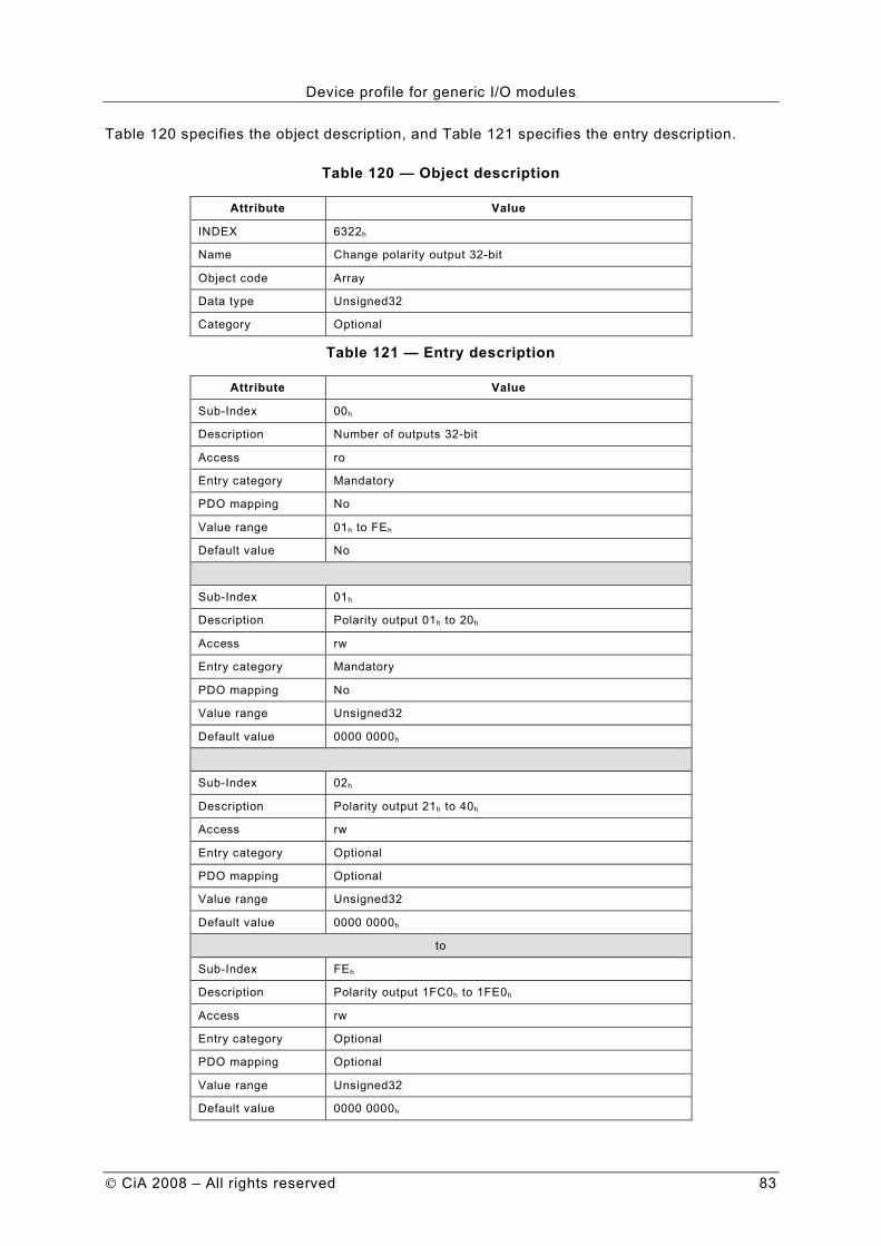
Device profile for generic I/O modules
CiA 2008 – All rights reserved 83
Table 120 specifies the object description, and Table 121 specifies the entry description.
Table 120 — Object description
Attribute Value
INDEX 6322h
Name Change polarity output 32-bit
Object code Array
Data type Unsigned32
Category Optional
Table 121 — Entry description
Attribute Value
Sub-Index 00h
Description Number of outputs 32-bit
Access ro
Entry category Mandatory
PDO mapping No
Value range 01h to FEh
Default value No
Sub-Index 01h
Description Polarity output 01h to 20h
Access rw
Entry category Mandatory
PDO mapping No
Value range Unsigned32
Default value 0000 0000h
Sub-Index 02h
Description Polarity output 21h to 40h
Access rw
Entry category Optional
PDO mapping Optional
Value range Unsigned32
Default value 0000 0000h
to
Sub-Index FEh
Description Polarity output 1FC0h to 1FE0h
Access rw
Entry category Optional
PDO mapping Optional
Value range Unsigned32
Default value 0000 0000h

Device profile for generic I/O modules
84 CiA 2008 – All rights reserved
8.3.18 Object 6326h: Error mode output 32-bit
These objects indicate, whether an output is set to a pre-defined error value (see also 6327h object) in case of an internal device failure a 'Stop Remote Node' indication.
1 = output value shall take the pre-defined condition as specified in 6327h object 0 = output value shall be kept if an error occurs
If the object is not supported, the device shall behave accordingly to the default value.
Table 122 specifies the object description, and Table 123 specifies the entry description.
Table 122 — Object description
Attribute Value
INDEX 6326h
Name Error mode output 32-bit
Object code Array
Data type Unsigned32
Category Optional
Table 123 — Entry description
Attribute Value
Sub-Index 00h
Description Number of outputs 32-bit
Access ro
Entry category Mandatory
PDO mapping No
Value range 01h to FEh
Default value No
Sub-Index 01h
Description Error mode output 01h to 20h
Access rw
Entry category Mandatory
PDO mapping Optional
Value range Unsigned32
Default value FFFF FFFFh
Sub-Index 02h
Description Error mode output 21h to 40h
Access rw
Entry category Optional
PDO mapping Optional
Value range Unsigned32
Default value FFFF FFFFh
to

Device profile for generic I/O modules
CiA 2008 – All rights reserved 85
Sub-Index FEh
Description Error mode output 1FC0h to 1FE0h
Access rw
Entry category Optional
PDO mapping Optional
Value range Unsigned32
Default value FFFF FFFFh
8.3.19 Object 6327h: Error value output 32-bit
On condition that the corresponding error mode is active, device failures (see chapter 5.2) shall set the outputs to the value configured by this object.
0 = output shall be set to ‘0’ in case of fault, if 6326h object is enabled 1 = output shall be set to ‘1’ in case of fault, if 6326h object is enabled
If the object is not supported, the device shall behave accordingly to the default value.
Table 124 specifies the object description, and Table 125 specifies the entry description.
Table 124 — Object description
Attribute Value
INDEX 6327h
Name Error value output 32-bit
Object code Array
Data type Unsigned32
Category Optional
Table 125 — Entry description
Attribute Value
Sub-Index 00h
Description Number of outputs 32-bit
Access ro
Entry category Mandatory
PDO mapping No
Value range 01h to FEh
Default value No
Sub-Index 01h
Description Error value output 01h to 20h
Access rw
Entry category Mandatory
PDO mapping Optional
Value range Unsigned32
Default value 0000 0000h

Device profile for generic I/O modules
86 CiA 2008 – All rights reserved
Sub-Index 02h
Description Error value output 21h to 40h
Access rw
Entry category Optional
PDO mapping Optional
Value range Unsigned32
Default value 0000 0000h
to
Sub-Index FEh
Description Error value output 1FC0h to 1FE0h
Access rw
Entry category Optional
PDO mapping Optional
Value range Unsigned32
Default value 0000 0000h
8.3.20 Object 6328h: Filter mask output 32-bit
This object defines an additional configurable output filter mask for a group of 32 outputs.
1 = output shall be set to the received output value 0 = don’t care the received output value is neglected for the appropriated output channel, the old output value shall be kept.
If the object is not supported, the device shall behave accordingly to the default value.
Table 126 specifies the object description, and Table 127 specifies the entry description.
Table 126 — Object description
Attribute Value
INDEX 6328h
Name Filter mask output 32-bit
Object code Array
Data type Unsigned32
Category Optional
Table 127 — Entry description
Attribute Value
Sub-Index 00h
Description Number of outputs 32-bit
Access ro
Entry category Mandatory
PDO mapping No
Value range 01h to FEh
Default value No
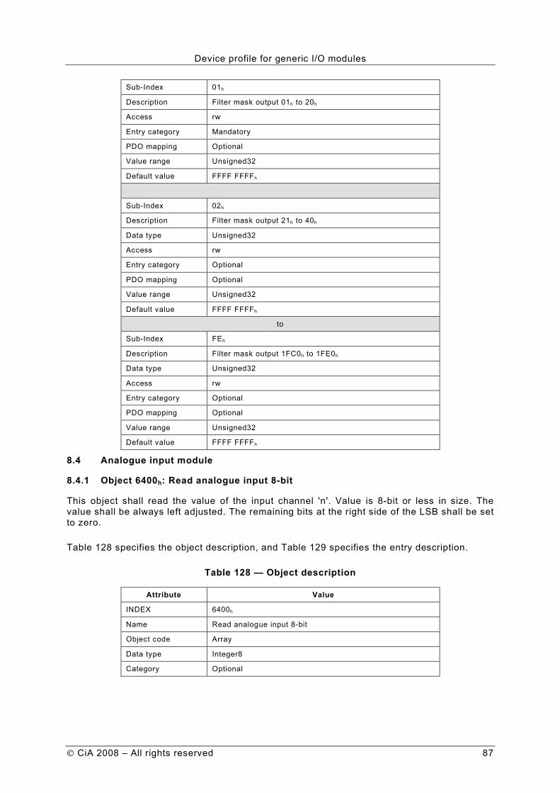
Device profile for generic I/O modules
CiA 2008 – All rights reserved 87
Sub-Index 01h
Description Filter mask output 01h to 20h
Access rw
Entry category Mandatory
PDO mapping Optional
Value range Unsigned32
Default value FFFF FFFFh
Sub-Index 02h
Description Filter mask output 21h to 40h
Data type Unsigned32
Access rw
Entry category Optional
PDO mapping Optional
Value range Unsigned32
Default value FFFF FFFFh
to
Sub-Index FEh
Description Filter mask output 1FC0h to 1FE0h
Data type Unsigned32
Access rw
Entry category Optional
PDO mapping Optional
Value range Unsigned32
Default value FFFF FFFFh
8.4 Analogue input module
8.4.1 Object 6400h: Read analogue input 8-bit
This object shall read the value of the input channel 'n'. Value is 8-bit or less in size. The value shall be always left adjusted. The remaining bits at the right side of the LSB shall be set to zero.
Table 128 specifies the object description, and Table 129 specifies the entry description.
Table 128 — Object description
Attribute Value
INDEX 6400h
Name Read analogue input 8-bit
Object code Array
Data type Integer8
Category Optional

Device profile for generic I/O modules
88 CiA 2008 – All rights reserved
Table 129 — Entry description
Attribute Value
Sub-Index 00h
Description Number of analogue inputs 8-bit
Access ro
Entry category Mandatory
PDO mapping No
Value range 01h to FEh
Default value No
Sub-Index 01h
Description Analogue input 01h
Access ro
Entry category Mandatory
PDO mapping Optional
Value range Integer8
Default value No
Sub-Index 02h
Description Analogue input 02h
Access ro
Entry category Optional
PDO mapping Optional
Value range Integer8
Default value No
to
Sub-Index FEh
Description Analogue input FEh
Access ro
Entry category Optional
PDO mapping Optional
Value range Integer8
Default value No
8.4.2 Object 6401h: Read analogue input 16-bit
This object shall read the value of the input channel 'n'. Value is 16-bit wide or less. The value shall be always left adjusted. The remaining bits at the right side of the LSB shall be set to zero.

Device profile for generic I/O modules
CiA 2008 – All rights reserved 89
Table 130 specifies the object description, and Table 131 specifies the entry description.
Table 130 — Object description
Attribute Value
INDEX 6401h
Name Read analogue input 16-bit
Object code Array
Data type Integer16
Category Conditional: Device with analog input
Table 131 — Entry description
Attribute Value
Sub-Index 00h
Description Number of analogue inputs 16-bit
Access ro
Entry category Mandatory
PDO mapping No
Value range 01h to FEh
Default value No
Sub-Index 01h
Description Analogue input 01h
Access ro
Entry category Mandatory
PDO mapping Default
Value range Integer16
Default value No
Sub-Index 02h
Description Analogue input 02h
Access ro
Entry category Optional
PDO mapping Default
Value range Integer16
Default value No
to
Sub-Index 0Ch
Description Analogue input 0Ch
Access ro
Entry category Optional
PDO mapping Default
Value range Integer
Default value No
to

Device profile for generic I/O modules
90 CiA 2008 – All rights reserved
Sub-Index 0Dh
Description Analogue input 0Dh
Access ro
Entry category Optional
PDO mapping Optional
Value range Integer16
Default value No
to
Sub-Index FEh
Description Analogue input FEh
Access ro
Entry category Optional
PDO mapping Optional
Value range Integer16
Default value No
8.4.3 Object 6402h: Read analogue input 32-bit
This object shall read the value of the input channel 'n'. Value is 32-bit wide or less. The value shall be always left adjusted. The remaining bits at the right side of the LSB shall be set to zero.
Table 132 specifies the object description, and Table 133 specifies the entry description
Table 132 — Object description
Attribute Value
INDEX 6402h
Name Read analogue input 32-bit
Object code Array
Data type Integer32
Category Optional
Table 133 — Entry description
Attribute Value
Sub-Index 00h
Description Number of analogue inputs 32-bit
Access ro
Entry category Mandatory
PDO mapping No
Value range 01h to FEh
Default value No

Device profile for generic I/O modules
CiA 2008 – All rights reserved 91
Sub-Index 01h
Description Analogue input 01h
Access ro
Entry category Mandatory
PDO mapping Optional
Value range Integer32
Default value No
Sub-Index 02h
Description Analogue input 02h
Access ro
Entry category Optional
PDO mapping Optional
Value range Integer32
Default value No
to
Sub-Index FEh
Description Analogue input FEh
Access ro
Entry category Optional
PDO mapping Optional
Value range Integer32
Default value No
8.4.4 Object 6403h: Read analogue input float
This object shall read the float value of the input channel 'n'. The float value shall be calculated by the following formula:
Float value = integer value x input scale + offset value
Table 134 specifies the object description, and Table 135 specifies the entry description.
Table 134 — Object description
Attribute Value
INDEX 6403h
Name Read analogue input float
Object code Array
Data type Real32
Category Optional

Device profile for generic I/O modules
92 CiA 2008 – All rights reserved
Table 135 — Entry description
Attribute Value
Sub-Index 00h
Description Number of analogue inputs float
Access ro
Entry category Mandatory
PDO mapping No
Value range 01h to FEh
Default value No
Sub-Index 01h
Description Analogue input 01h
Access ro
Entry category Mandatory
PDO mapping Optional
Value range Real32
Default value No
Sub-Index 02h
Description Analogue input 02h
Access ro
Entry category Optional
PDO mapping Optional
Value range Real32
Default value No
to
Sub-Index FEh
Description Analogue input FEh
Access ro
Entry category Optional
PDO mapping Optional
Value range Real32
Default value No
8.4.5 Object 6404h: Read manufacturer-specific analogue input
This object shall read the manufacturer-specific value of the input channel 'n'.

Device profile for generic I/O modules
CiA 2008 – All rights reserved 93
Table 136 specifies the object description, and Table 137 specifies the entry description.
Table 136 — Object description
Attribute Value
INDEX 6404h
Name Read manufacturer specific analogue input
Object code Array
Data type Manufacturer-specific
Category Optional
Table 137 — Entry description
Attribute Value
Sub-Index 00h
Description Number of analogue inputs
Access ro
Entry category Mandatory
PDO mapping No
Value range 01h to FEh
Default value No
Sub-Index 01h
Description Analogue input 01h
Access ro
Entry category Mandatory
PDO mapping Optional
Value range Manufacturer-specific
Default value No
Sub-Index 02h
Description Analogue input 02h
Access ro
Entry category Optional
PDO mapping Optional
Value range Manufacturer-specific
Default value No
to
Sub-Index FEh
Description Analogue input FEh
Access ro
Entry category Optional
PDO mapping Optional
Value range Manufacturer-specific
Default value No

Device profile for generic I/O modules
94 CiA 2008 – All rights reserved
8.5 Analogue output module
8.5.1 Object 6410h: Write analogue output 8-bit
This object shall write an integer8 value to the output channel 'n'. The value shall be always left adjusted.
Table 138 specifies the object description, and Table 139 specifies the entry description.
Table 138 — Object description
Attribute Value
INDEX 6410h
Name Write analogue output 8-bit
Object code Array
Data type Integer8
Category Optional
Table 139 — Entry description
Attribute Value
Sub-Index 00h
Description Number of analogue outputs 8-bit
Access ro
Entry category Mandatory
PDO mapping No
Value range 01h to FEh
Default value No
Sub-Index 01h
Description Analogue output 01h
Access rw
Entry category Mandatory
PDO mapping Optional
Value range Integer8
Default value 00h
Sub-Index 02h
Description Analogue output 02h
Access rw
Entry category Optional
PDO mapping Optional
Value range Integer8
Default value 00h
to

Device profile for generic I/O modules
CiA 2008 – All rights reserved 95
Sub-Index FEh
Description Analogue output FEh
Access rw
Entry category Optional
PDO mapping Optional
Value range Integer8
Default value 00h
8.5.2 Object 6411h: Write analogue output 16-bit
This object shall write an integer16 value to the output channel 'n'. The value shall be always left adjusted.
Table 140 specifies the object description, and Table 141 specifies the entry description.
Table 140 — Object description
Attribute Value
INDEX 6411h
Name Write analogue output 16-bit
Object code Array
Data type Integer16
Category Conditional: Device with analogue output
Table 141 — Entry description
Attribute Value
Sub-Index 00h
Description Number of analogue outputs 16-bit
Access ro
Entry category Mandatory
PDO mapping No
Value range 01h to FEh
Default value No
Sub-Index 01h
Description Analogue output 01h
Access rw
Entry category Mandatory
PDO mapping Default
Value range Integer16
Default value 0000h

Device profile for generic I/O modules
96 CiA 2008 – All rights reserved
Sub-Index 02h
Description Analogue output 02h
Access rw
Entry category Optional
PDO mapping Default
Value range Integer
Default value 0000h
to
Sub-Index 0Ch
Description Analogue output 0Ch
Access rw
Entry category Optional
PDO mapping Default
Value range Integer16
Default value 0000h
Sub-Index 0Dh
Description Analogue output 0Dh
Access rw
Entry category Optional
PDO mapping Optional
Value range Integer16
Default value 0000h
to
Sub-Index FEh
Description Analogue output FEh
Access rw
Entry category Optional
PDO mapping Optional
Value range Integer16
Default value 0000h
8.5.3 Object 6412h: Write analogue output 32-bit
This object shall write an integer32 value to the output channel 'n'. The value shall be always left adjusted.
Table 142 specifies the object description, and Table 143 specifies the entry description.
Table 142 — Object description
Attribute Value
INDEX 6412h
Name Write analogue output 32-bit
Object code Array
Data type Integer32
Category Optional

Device profile for generic I/O modules
CiA 2008 – All rights reserved 97
Table 143 — Entry description
Attribute Value
Sub-Index 00h
Description Number of analogue outputs 32-bit
Access ro
Entry category Mandatory
PDO mapping No
Value range 01h to FEh
Default value No
Sub-Index 01h
Description Analogue output 01h
Access rw
Entry category Mandatory
PDO mapping Optional
Value range Integer32
Default value 0000 0000h
Sub-Index 02h
Description Analogue output 02h
Access rw
Entry category Optional
PDO mapping Optional
Value range Integer32
Default value 0000 0000h
to
Sub-Index FEh
Description Analogue output FEh
Access rw
Entry category Optional
PDO mapping Optional
Value range Integer32
Default value 0000 0000h
8.5.4 Object 6413h: Write analogue output float
This object shall write the float value to the output channel 'n'. The Integer value shall be calculated by the following formula:
Float value – Output offset Integer value = ------------------------------------
Output scale

Device profile for generic I/O modules
98 CiA 2008 – All rights reserved
Table 144 specifies the object description, and Table 145 specifies the entry description.
Table 144 — Object description
Attribute Value
INDEX 6413h
Name Write analogue output float
Object code Array
Data type Real32
Category Optional
Table 145 — Entry description
Attribute Value
Sub-Index 00h
Description Number of analogue outputs float
Access ro
Entry category Mandatory
PDO mapping No
Value range 01h to FEh
Default value No
Sub-Index 01h
Description Analogue output 01h
Access rw
Entry category Mandatory
PDO mapping Optional
Value range Real32
Default value 0,0
Sub-Index 02h
Description Analogue output 02h
Access rw
Entry category Optional
PDO mapping Optional
Value range Real32
Default value 0,0
to
Sub-Index FEh
Description Analogue output FEh
Access rw
Entry category Optional
PDO mapping Optional
Value range Real32
Default value 0,0

Device profile for generic I/O modules
CiA 2008 – All rights reserved 99
8.5.5 Object 6414h: Write manufacturer-specific analogue output
Writes the manufacturer-specific value to the output channel 'n'.
Table 146 specifies the object description, and Table 147 specifies the entry description.
Table 146 — Object description
Attribute Value
INDEX 6414h
Name Write manufacturer specific analogue output
Object code Record or Array
Data type Manufacturer-specific
Category Optional
Table 147 — Entry description
Attribute Value
Sub-Index 00h
Description Number of analogue outputs
Access ro
Entry category Mandatory
PDO mapping No
Value range 01h to FEh
Default value No
Sub-Index 01h
Description Analogue output 01h
Access rw
Entry category Mandatory
PDO mapping Optional
Value range Manufacturer-specific
Default value Manufacturer-specific
Sub-Index 02h
Description Analogue output 02h
Access rw
Entry category Optional
PDO mapping Optional
Value range Manufacturer-specific
Default value Manufacturer-specific
to

Device profile for generic I/O modules
100 CiA 2008 – All rights reserved
Sub-Index FEh
Description Analogue output FEh
Access rw
Entry category Optional
PDO mapping Optional
Value range Manufacturer-specific
Default value Manufacturer-specific
8.6 Analogue input set-ups
8.6.1 Object 6420h
Reserved for compatibility reason.
8.6.2 Object 6421h: Analogue input interrupt trigger selection
This object determines, which events shall cause an interrupt for a specific channel. Figure 8 specifies the object structure and Table 148 specifies the value definition. All bits set to 1b shall trigger the corresponding analogue input. If the object is not supported, the device shall behave accordingly to the default value.
7 6 5 4 3 2 1 0
r r r Bit 4 Bit 3 Bit 2 Bit 1 Bit 0
MSB LSB
Figure 8 — Object structure
Table 148 — Value definition
Field Value Definition
Bit 0 0b
1b Upper limit not exceeded
Upper limit exceeded
Bit 1 0b
1b Input not below lower limit
Input below lower limit
Bit 2 0b 1b
Input not changed by more than delta Input changed by more than delta
Bit 3 0b
1b Input not reduced by more than negative delta
Input reduced by more than negative delta
Bit 4 0b
1b Input not increased by more than positive delta
Input increased by more than positive delta
r 0b Reserved for future use
Table 149 specifies the object description, and Table 150 specifies the entry description.
Table 149 — Object description
Attribute Value
INDEX 6421h
Name Interrupt trigger selection
Object code Array
Data type Unsigned8
Category Optional
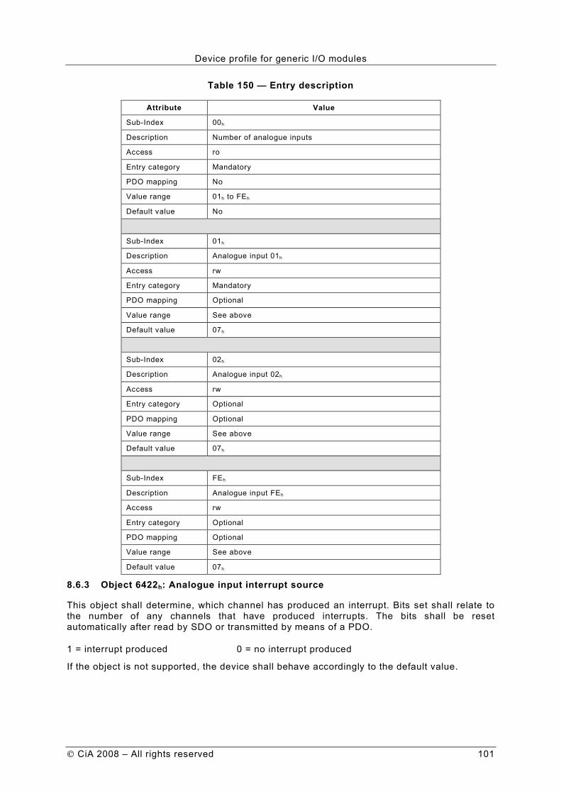
Device profile for generic I/O modules
CiA 2008 – All rights reserved 101
Table 150 — Entry description
Attribute Value
Sub-Index 00h
Description Number of analogue inputs
Access ro
Entry category Mandatory
PDO mapping No
Value range 01h to FEh
Default value No
Sub-Index 01h
Description Analogue input 01h
Access rw
Entry category Mandatory
PDO mapping Optional
Value range See above
Default value 07h
Sub-Index 02h
Description Analogue input 02h
Access rw
Entry category Optional
PDO mapping Optional
Value range See above
Default value 07h
Sub-Index FEh
Description Analogue input FEh
Access rw
Entry category Optional
PDO mapping Optional
Value range See above
Default value 07h
8.6.3 Object 6422h: Analogue input interrupt source
This object shall determine, which channel has produced an interrupt. Bits set shall relate to the number of any channels that have produced interrupts. The bits shall be reset automatically after read by SDO or transmitted by means of a PDO.
1 = interrupt produced 0 = no interrupt produced
If the object is not supported, the device shall behave accordingly to the default value.

Device profile for generic I/O modules
102 CiA 2008 – All rights reserved
Table 151 specifies the object description, and Table 152 specifies the entry description.
Table 151 — Object description
Attribute Value
INDEX 6422h
Name Analogue input Interrupt Source
Object code Array
Data type Unsigned32
Category Optional
Table 152 — Entry description
Attribute Value
Sub-Index 00h
Description Number of interrupt source banks
Access ro
Entry category Mandatory
PDO mapping No
Value range 01h to 08h
Default value No
Sub-Index 01h
Description Interrupt source bank 01h
Access ro
Entry category Mandatory
PDO mapping Optional
Value range Unsigned32
Default value No
Sub-Index 02h
Description Interrupt source bank 02h
Access ro
Entry category Optional
PDO mapping Optional
Value range Unsigned32
Default value No
to
Sub-Index 08h
Description Interrupt source bank 08h
Access ro
Entry category Optional
PDO mapping Optional
Value range Unsigned32
Default value No
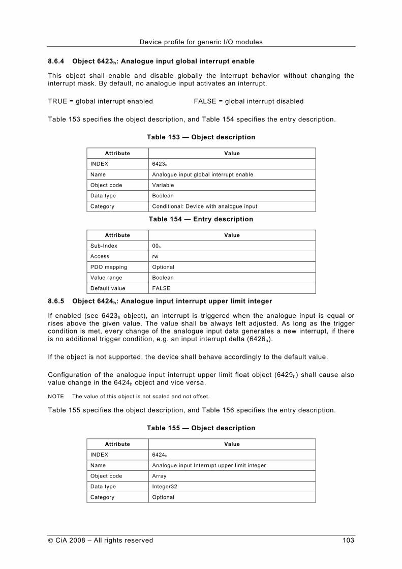
Device profile for generic I/O modules
CiA 2008 – All rights reserved 103
8.6.4 Object 6423h: Analogue input global interrupt enable
This object shall enable and disable globally the interrupt behavior without changing the interrupt mask. By default, no analogue input activates an interrupt.
TRUE = global interrupt enabled FALSE = global interrupt disabled
Table 153 specifies the object description, and Table 154 specifies the entry description.
Table 153 — Object description
Attribute Value
INDEX 6423h
Name Analogue input global interrupt enable
Object code Variable
Data type Boolean
Category Conditional: Device with analogue input
Table 154 — Entry description
Attribute Value
Sub-Index 00h
Access rw
PDO mapping Optional
Value range Boolean
Default value FALSE
8.6.5 Object 6424h: Analogue input interrupt upper limit integer
If enabled (see 6423h object), an interrupt is triggered when the analogue input is equal or rises above the given value. The value shall be always left adjusted. As long as the trigger condition is met, every change of the analogue input data generates a new interrupt, if there is no additional trigger condition, e.g. an input interrupt delta (6426h).
If the object is not supported, the device shall behave accordingly to the default value.
Configuration of the analogue input interrupt upper limit float object (6429h) shall cause also value change in the 6424h object and vice versa.
NOTE The value of this object is not scaled and not offset.
Table 155 specifies the object description, and Table 156 specifies the entry description.
Table 155 — Object description
Attribute Value
INDEX 6424h
Name Analogue input Interrupt upper limit integer
Object code Array
Data type Integer32
Category Optional

Device profile for generic I/O modules
104 CiA 2008 – All rights reserved
Table 156 — Entry description
Attribute Value
Sub-Index 00h
Description Number of analogue inputs
Access ro
Entry category Mandatory
PDO mapping No
Value range 01h to FEh
Default No
Sub-Index 01h
Description Analogue input 01h
Access rw
Entry category Mandatory
PDO mapping Optional
Value range Integer32
Default value 0000 0000h
Sub-Index 02h
Description Analogue input 02h
Access rw
Entry category Optional
PDO mapping Optional
Value range Integer32
Default value 0000 0000h
to
Sub-Index FEh
Description Analogue input FEh
Access rw
Entry category Optional
PDO mapping Optional
Value range Integer32
Default value 0000 0000h
8.6.6 Object 6425h: Analogue input interrupt lower limit integer
If enabled (see 6423h object), an interrupt is triggered when the analogue input falls below the given value. The value shall be always left adjusted. As long as the trigger condition is met, every change of the analogue input data generates a new interrupt, if there is no additional trigger condition, e.g. an input interrupt delta (6426h).
If the object is not supported, the device shall behave accordingly to the default value.
Configuration of the analogue input interrupt lower limit float object (642Ah) shall cause also value change in the 6425h object and vice versa.
NOTE The value of this object is not scaled and not offset.

Device profile for generic I/O modules
CiA 2008 – All rights reserved 105
Table 157 specifies the object description, and Table 158 specifies the entry description.
Table 157 — Object description
Attribute Value
INDEX 6425h
Name Analogue input interrupt lower limit integer
Object code Array
Data type Integer32
Category Optional
Table 158 — Entry description
Attribute Value
Sub-Index 00h
Description Number of analogue inputs
Access ro
Entry category Mandatory
PDO mapping No
Value range 01h to FEh
Default value No
Sub-Index 01h
Description Analogue input 01h
Access rw
Entry category Optional
PDO mapping Optional
Value range Integer32
Default value 0000 0000h
Sub-Index 02h
Description Analogue input 02h
Access rw
Entry category Optional
PDO mapping Optional
Value range Integer32
Default value 0000 0000h
to
Sub-Index FEh
Description Analogue input FEh
Access rw
Entry category Optional
PDO mapping Optional
Value range Integer32
Default value 0000 0000h

Device profile for generic I/O modules
106 CiA 2008 – All rights reserved
8.6.7 Object 6426h: Analogue input interrupt delta unsigned
This object shall set the delta value (rising or falling above or below the last communicated value) for interrupt-enabled analogue inputs (see 6423h object).
If the object is not supported, the device shall behave accordingly to the default value.
Configuration of the analogue input interrupt delta float object (642Bh) shall cause also value change in 6426h object and vice versa.
NOTE The value of this object is not scaled and not offset.
Table 159 specifies the object description, and Table 160 specifies the entry description.
Table 159 — Object description
Attribute Value
INDEX 6426h
Name Analogue input interrupt delta unsigned
Object code Array
Data type Unsigned32
Category Optional
Table 160 — Entry description
Attribute Value
Sub-Index 00h
Description Number of analogue inputs
Access ro
Entry category Mandatory
PDO mapping No
Value range 01h to FEh
Default value No
Sub-Index 01h
Description Analogue input 01h
Access rw
Entry category Mandatory
PDO mapping Optional
Value range Unsigned32
Default value 0000 0000h
Sub-Index 02h
Description Analogue input 02h
Access rw
Entry category Optional
PDO mapping Optional
Value range Unsigned32
Default value 0000 0000h
to
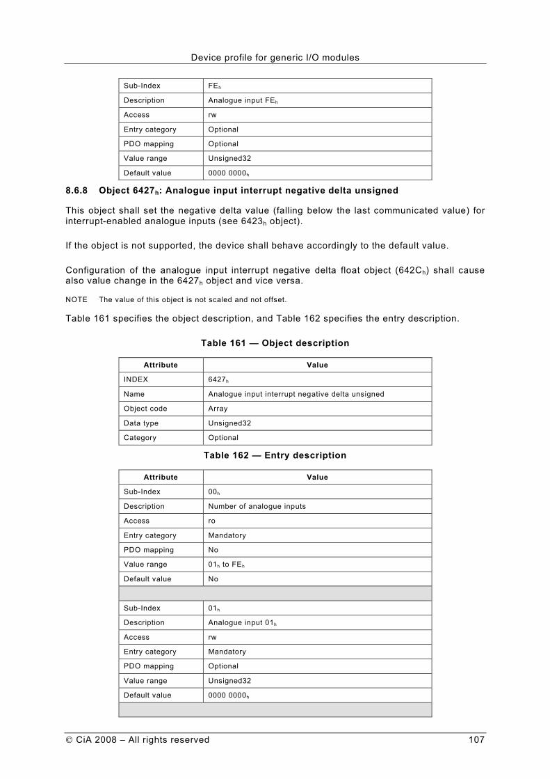
Device profile for generic I/O modules
CiA 2008 – All rights reserved 107
Sub-Index FEh
Description Analogue input FEh
Access rw
Entry category Optional
PDO mapping Optional
Value range Unsigned32
Default value 0000 0000h
8.6.8 Object 6427h: Analogue input interrupt negative delta unsigned
This object shall set the negative delta value (falling below the last communicated value) for interrupt-enabled analogue inputs (see 6423h object).
If the object is not supported, the device shall behave accordingly to the default value.
Configuration of the analogue input interrupt negative delta float object (642Ch) shall cause also value change in the 6427h object and vice versa.
NOTE The value of this object is not scaled and not offset.
Table 161 specifies the object description, and Table 162 specifies the entry description.
Table 161 — Object description
Attribute Value
INDEX 6427h
Name Analogue input interrupt negative delta unsigned
Object code Array
Data type Unsigned32
Category Optional
Table 162 — Entry description
Attribute Value
Sub-Index 00h
Description Number of analogue inputs
Access ro
Entry category Mandatory
PDO mapping No
Value range 01h to FEh
Default value No
Sub-Index 01h
Description Analogue input 01h
Access rw
Entry category Mandatory
PDO mapping Optional
Value range Unsigned32
Default value 0000 0000h
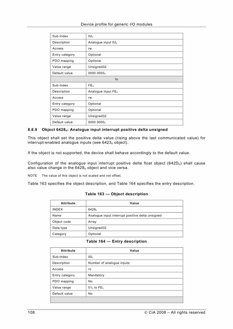
Device profile for generic I/O modules
108 CiA 2008 – All rights reserved
Sub-Index 02h
Description Analogue input 02h
Access rw
Entry category Optional
PDO mapping Optional
Value range Unsigned32
Default value 0000 0000h
to
Sub-Index FEh
Description Analogue input FEh
Access rw
Entry category Optional
PDO mapping Optional
Value range Unsigned32
Default value 0000 0000h
8.6.9 Object 6428h: Analogue input interrupt positive delta unsigned
This object shall set the positive delta value (rising above the last communicated value) for interrupt-enabled analogue inputs (see 6423h object).
If the object is not supported, the device shall behave accordingly to the default value.
Configuration of the analogue input interrupt positive delta float object (642Dh) shall cause also value change in the 6428h object and vice versa.
NOTE The value of this object is not scaled and not offset.
Table 163 specifies the object description, and Table 164 specifies the entry description.
Table 163 — Object description
Attribute Value
INDEX 6428h
Name Analogue input interrupt positive delta unsigned
Object code Array
Data type Unsigned32
Category Optional
Table 164 — Entry description
Attribute Value
Sub-Index 00h
Description Number of analogue inputs
Access ro
Entry category Mandatory
PDO mapping No
Value range 01h to FEh
Default value No

Device profile for generic I/O modules
CiA 2008 – All rights reserved 109
Sub-Index 01h
Description Analogue input 01h
Access rw
Entry category Mandatory
PDO mapping Optional
Value range Unsigned32
Default value 0000 0000h
Sub-Index 02h
Description Analogue input 02h
Access rw
Entry category Optional
PDO mapping Optional
Value range Unsigned32
Default value 0000 0000h
to
Sub-Index FEh
Description Analogue input FEh
Access rw
Entry category Optional
PDO mapping Optional
Value range Unsigned32
Default value 0000 0000h
8.6.10 Object 6429h: Analogue input interrupt upper limit float
This object shall set the converted upper limits for interrupt-enabled analogue inputs (see 6423h object). As long as the trigger condition is met, every change of the analogue input data generates a new interrupt, if there is no additional trigger condition, e.g. an input interrupt delta (642Bh).
If the object is not supported, the device shall behave accordingly to the default value.
Configuration of the analogue input interrupt upper limit integer object (6424h) shall cause also value change in the 6429h object and vice versa.
NOTE The value of this object is not scaled and not offset.
Table 165 specifies the object description, and Table 166 specifies the entry description.
Table 165 — Object description
Attribute Value
INDEX 6429h
Name Analogue input interrupt upper limit float
Object code Array
Data type Real32
Category Optional

Device profile for generic I/O modules
110 CiA 2008 – All rights reserved
Table 166 — Entry description
Attribute Value
Sub-Index 00h
Description Number of analogue inputs
Access ro
Entry category Mandatory
PDO mapping No
Value range 01h to FEh
Default value No
Sub-Index 01h
Description Analogue input 01h
Access rw
Entry category Mandatory
PDO mapping Optional
Value range Real32
Default value 0,0
Sub-Index 02h
Description Analogue input 02h
Access rw
Entry category Optional
PDO mapping Optional
Value range Real32
Default value 0,0
to
Sub-Index FEh
Description Analogue input FEh
Access rw
Entry category Optional
PDO mapping Optional
Value range Real32
Default value 0,0
8.6.11 Object 642Ah: Analogue input interrupt lower limit float
This object shall set the lower limits for interrupt-enabled analogue inputs (see 6423h object). As long as the trigger condition is met, every change of the analogue input data generates a new interrupt, if there is no additional trigger condition, e.g. an input interrupt delta (642Bh).
If the object is not supported, the device shall behave accordingly to the default value.
Configuration of the analogue input interrupt lower limit integer object (6425h) shall cause also value change in the 642Ah object and vice versa.
NOTE The value of this object is not scaled and not offset.

Device profile for generic I/O modules
CiA 2008 – All rights reserved 111
Table 167 specifies the object description, and Table 168 specifies the entry description.
Table 167 — Object description
Attribute Value
INDEX 642Ah
Name Analogue input interrupt lower limit float
Object code Array
Data type Real32
Category Optional
Table 168 — Entry description
Attribute Value
Sub-Index 00h
Description Number analogue inputs
Access ro
Entry category Mandatory
PDO mapping No
Value range 01h to FEh
Default value No
Sub-Index 01h
Description Analogue input 01h
Access rw
Entry category Mandatory
PDO mapping Optional
Value range Real32
Default value 0,0
Sub-Index 02h
Description Analogue input 02h
Access rw
Entry category Optional
PDO mapping Optional
Value range Real32
Default value 0,0
to
Sub-Index FEh
Description Analogue input FEh
Access rw
Entry category Optional
PDO mapping Optional
Value range Real32
Default value 0,0

Device profile for generic I/O modules
112 CiA 2008 – All rights reserved
8.6.12 Object 642Bh: Analogue input interrupt delta float
This object shall set the delta value (rising or falling above or below the last sample) in float format for interrupt-enabled analogue inputs (see 6423h object).
If the object is not supported, the device shall behave accordingly to the default value.
Configuration of the analogue input interrupt delta unsigned object (6426h) shall cause also value change in the 642Bh object and vice versa.
NOTE The value of this object is not scaled and not offset.
Table 169 specifies the object description, and Table 170 specifies the entry description.
Table 169 — Object description
Attribute Value
INDEX 642Bh
Name Analogue input interrupt delta float
Object code Array
Data type Real32
Category Optional
Table 170 — Entry description
Attribute Value
Sub-Index 00h
Description Number of analogue inputs
Access ro
Entry category Mandatory
PDO mapping No
Value range 01h to FEh
Default value No
Sub-Index 01h
Description Analogue input 01h
Access rw
Entry category Mandatory
PDO mapping Optional
Value range Real32
Default value 0,0
Sub-Index 02h
Description Analogue input 02h
Access rw
Entry category Optional
PDO mapping Optional
Value range Real32
Default value 0,0
to

Device profile for generic I/O modules
CiA 2008 – All rights reserved 113
Sub-Index FEh
Description Analogue input FEh
Access rw
Entry category Optional
PDO mapping Optional
Value range Real32
Default value 0,0
8.6.13 Object 642Ch: Analogue input interrupt negative delta float
This object shall set the negative delta value (falling below the last sample) in float format for interrupt-enabled analogue inputs (see 6423h object).
If the object is not supported, the device shall behave accordingly to the default value.
Configuration of the analogue input interrupt negative delta unsigned object (6427h) shall cause also value change in the 642Ch object and vice versa.
NOTE The value of this object is not scaled and not offset.
Table 171 specifies the object description, and Table 172 specifies the entry description.
Table 171 — Object description
Attribute Value
INDEX 642Ch
Name Analogue input interrupt negative delta float
Object code Array
Data type Real32
Category Optional
Table 172 — Entry description
Attribute Value
Sub-Index 00h
Description Number of analogue inputs
Access ro
Entry category Mandatory
PDO mapping No
Value range 01h to FEh
Default value No
Sub-Index 01h
Description Analogue input 01h
Access rw
Entry category Mandatory
PDO mapping Optional
Value range Real32
Default value 0,0
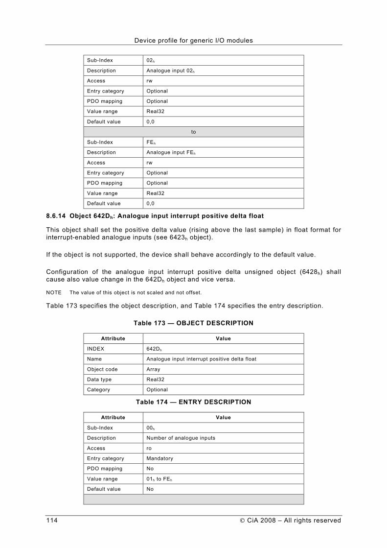
Device profile for generic I/O modules
114 CiA 2008 – All rights reserved
Sub-Index 02h
Description Analogue input 02h
Access rw
Entry category Optional
PDO mapping Optional
Value range Real32
Default value 0,0
to
Sub-Index FEh
Description Analogue input FEh
Access rw
Entry category Optional
PDO mapping Optional
Value range Real32
Default value 0,0
8.6.14 Object 642Dh: Analogue input interrupt positive delta float
This object shall set the positive delta value (rising above the last sample) in float format for interrupt-enabled analogue inputs (see 6423h object).
If the object is not supported, the device shall behave accordingly to the default value.
Configuration of the analogue input interrupt positive delta unsigned object (6428h) shall cause also value change in the 642Dh object and vice versa.
NOTE The value of this object is not scaled and not offset.
Table 173 specifies the object description, and Table 174 specifies the entry description.
Table 173 — OBJECT DESCRIPTION
Attribute Value
INDEX 642Dh
Name Analogue input interrupt positive delta float
Object code Array
Data type Real32
Category Optional
Table 174 — ENTRY DESCRIPTION
Attribute Value
Sub-Index 00h
Description Number of analogue inputs
Access ro
Entry category Mandatory
PDO mapping No
Value range 01h to FEh
Default value No

Device profile for generic I/O modules
CiA 2008 – All rights reserved 115
Sub-Index 01h
Description Analogue input 01h
Access rw
Entry category Mandatory
PDO mapping Optional
Value range Real32
Default value 0,0
Sub-Index 02h
Description Analogue input 02h
Access rw
Entry category Optional
PDO mapping Optional
Value range Real32
Default value 0,0
to
Sub-Index FEh
Description Analogue input FEh
Access rw
Entry category Optional
PDO mapping Optional
Value range Real32
Default value 0,0
8.6.15 Object 642Eh: Analogue input offset float
This object shall set the offsets in float format for input data (6403h object) for channel 'n'.
If the object is not supported, the device shall behave accordingly to 6431h object, or if that object is also not supported, the device shall behave accordingly to the default value.
Configuration of the analogue input offset integer object (6431h) shall cause also value change in the 642Eh object and vice versa.
Table 175 specifies the object description, and Table 176 specifies the entry description.
Table 175 — OBJECT DESCRIPTION
Attribute Value
INDEX 642Eh
Name Analogue input offset float
Object code Array
Data type Real32
Category Optional

Device profile for generic I/O modules
116 CiA 2008 – All rights reserved
Table 176 — ENTRY DESCRIPTION
Attribute Value
Sub-Index 00h
Description Number of analogue inputs
Access ro
Entry category Mandatory
PDO mapping No
Value range 01h to FEh
Default value No
Sub-Index 01h
Description Analogue input 01h
Access rw
Entry category Mandatory
PDO mapping Optional
Value range Real32
Default value 0,0
Sub-Index 02h
Description Analogue input 02h
Access rw
Entry category Optional
PDO mapping Optional
Value range Real32
Default value 0,0
to
Sub-Index FEh
Description Analogue input FEh
Access rw
Entry category Optional
PDO mapping Optional
Value range Real32
Default value 0,0
8.6.16 Object 642Fh: Analogue input pre-scaling float
This object shall set the pre-scaling in float format for input data (6403h object).
If the object is not supported, the device shall behave accordingly to 6432h object, or if that object is also not supported, the device shall behave accordingly to the default value.
Configuration of the analogue input pre-scaling integer object (6432h) shall cause also value change in the 642Fh object and vice versa.

Device profile for generic I/O modules
CiA 2008 – All rights reserved 117
Table 177 specifies the object description, and Table 178 specifies the entry description.
Table 177 — OBJECT DESCRIPTION
Attribute Value
INDEX 642Fh
Name Analogue input pre-scaling float
Object code Array
Data type Real32
Category Optional
Table 178 — Entry description
Attribute Value
Sub-Index 00h
Description Number of analogue inputs
Access ro
Entry category Mandatory
PDO mapping No
Value range 01h to FEh
Default value No
Sub-Index 01h
Description Analogue input 01h
Access rw
Entry category Mandatory
PDO mapping Optional
Value range Real32
Default value 1,0
Sub-Index 02h
Description Analogue input 02h
Access rw
Entry category Optional
PDO mapping Optional
Value range Real32
Default value 1,0
to
Sub-Index FEh
Description Analogue input FEh
Access rw
Entry category Optional
PDO mapping Optional
Value range Real32
Default value 1,0
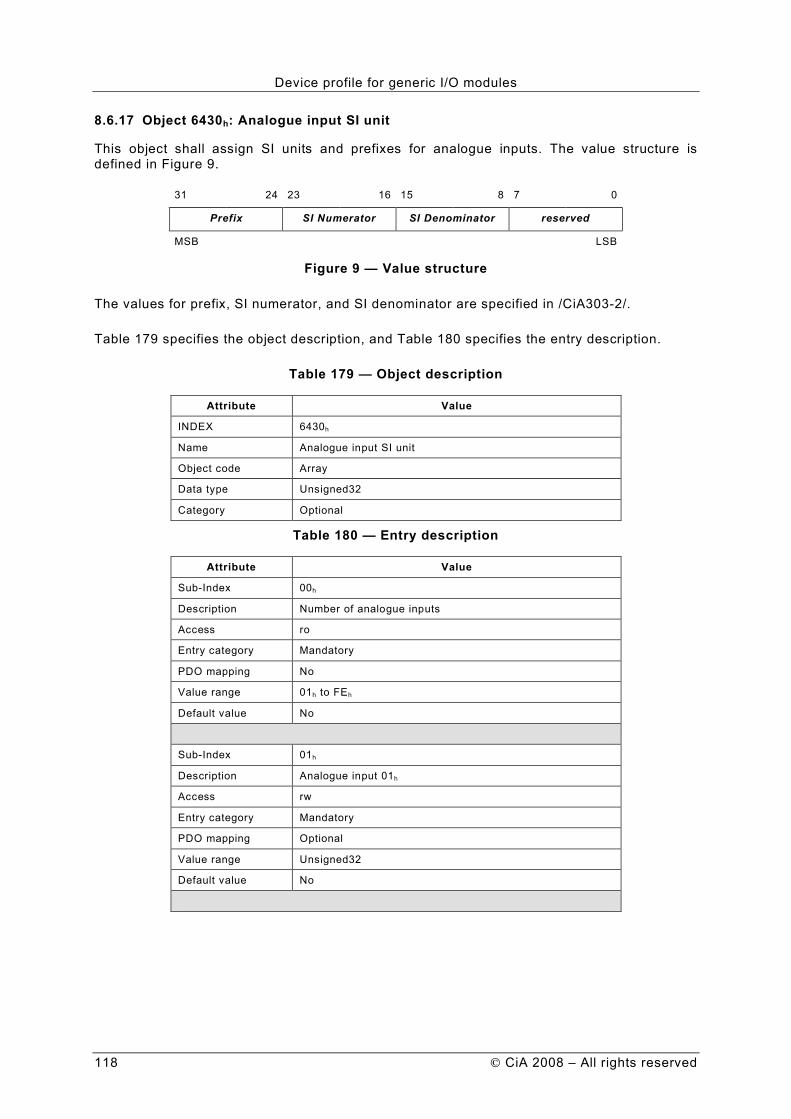
Device profile for generic I/O modules
118 CiA 2008 – All rights reserved
8.6.17 Object 6430h: Analogue input SI unit
This object shall assign SI units and prefixes for analogue inputs. The value structure is defined in Figure 9.
31 24 23 16 15 8 7 0
Prefix SI Numerator SI Denominator reserved
MSB LSB
Figure 9 — Value structure
The values for prefix, SI numerator, and SI denominator are specified in /CiA303-2/.
Table 179 specifies the object description, and Table 180 specifies the entry description.
Table 179 — Object description
Attribute Value
INDEX 6430h
Name Analogue input SI unit
Object code Array
Data type Unsigned32
Category Optional
Table 180 — Entry description
Attribute Value
Sub-Index 00h
Description Number of analogue inputs
Access ro
Entry category Mandatory
PDO mapping No
Value range 01h to FEh
Default value No
Sub-Index 01h
Description Analogue input 01h
Access rw
Entry category Mandatory
PDO mapping Optional
Value range Unsigned32
Default value No

Device profile for generic I/O modules
CiA 2008 – All rights reserved 119
Sub-Index 02h
Description Analogue input 02h
Access rw
Entry category Optional
PDO mapping Optional
Value range Unsigned32
Default value No
to
Sub-Index FEh
Description Analogue input FEh
Access rw
Entry category Optional
PDO mapping Optional
Value range Unsigned32
Default value No
8.6.18 Object 6431h: Analogue input offset integer
This object shall set the offset in integer format for input data (6403h object).
If the object is not supported, the device shall behave accordingly to 642Eh object, or if that object is also not supported, the device shall behave accordingly to the default value.
Configuration of the analogue input offset float object (642Eh) shall cause also value change in the 6431h object and vice versa.
Table 181 specifies the object description, and Table 182 specifies the entry description.
Table 181 — Object description
Attribute Value
INDEX 6431h
Name Analogue input offset integer
Object code Array
Data type Integer32
Category Optional
Table 182 — Entry description
Attribute Value
Sub-Index 00h
Description Number of analogue inputs
Access ro
Entry category Mandatory
PDO mapping No
Value range 01h to FEh
Default value No
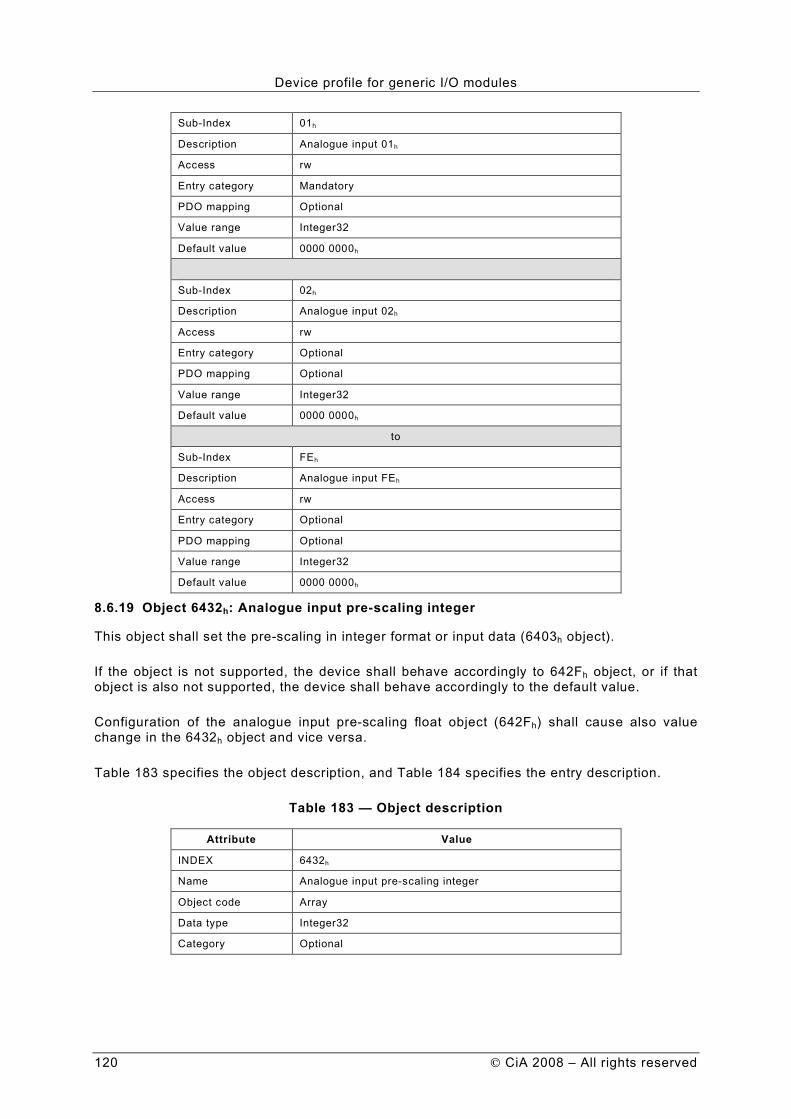
Device profile for generic I/O modules
120 CiA 2008 – All rights reserved
Sub-Index 01h
Description Analogue input 01h
Access rw
Entry category Mandatory
PDO mapping Optional
Value range Integer32
Default value 0000 0000h
Sub-Index 02h
Description Analogue input 02h
Access rw
Entry category Optional
PDO mapping Optional
Value range Integer32
Default value 0000 0000h
to
Sub-Index FEh
Description Analogue input FEh
Access rw
Entry category Optional
PDO mapping Optional
Value range Integer32
Default value 0000 0000h
8.6.19 Object 6432h: Analogue input pre-scaling integer
This object shall set the pre-scaling in integer format or input data (6403h object).
If the object is not supported, the device shall behave accordingly to 642Fh object, or if that object is also not supported, the device shall behave accordingly to the default value.
Configuration of the analogue input pre-scaling float object (642Fh) shall cause also value change in the 6432h object and vice versa.
Table 183 specifies the object description, and Table 184 specifies the entry description.
Table 183 — Object description
Attribute Value
INDEX 6432h
Name Analogue input pre-scaling integer
Object code Array
Data type Integer32
Category Optional

Device profile for generic I/O modules
CiA 2008 – All rights reserved 121
Table 184 — Entry description
Attribute Value
Sub-Index 00h
Description Number of analogue inputs
Access ro
Entry category Mandatory
PDO mapping No
Value range 01h to FEh
Default value No
Sub-Index 01h
Description Analogue input 01h
Access rw
Entry category Mandatory
PDO mapping Optional
Value range Integer32
Default value 0000 0001h
Sub-Index 02h
Description Analogue input 02h
Access rw
Entry category Optional
PDO mapping Optional
Value range Integer32
Default value 0000 0001h
to
Sub-Index FEh
Description Analogue input FEh
Access rw
Entry category Optional
PDO mapping Optional
Value range Integer32
Default value 0000 0001h
8.7 Analogue output set-ups
8.7.1 Object 6440h
Reserved for compatibility reason.
8.7.2 Object 6441h: Analogue output offset float
This object shall set the offset in float format for output data (6413h object).
If the object is not supported, the device shall behave accordingly to 6446h object, or if that object is also not supported, the device shall behave accordingly to the default value.

Device profile for generic I/O modules
122 CiA 2008 – All rights reserved
Configuration of the analogue output offset integer object (6446h) shall cause also value change in the 6441h object and vice versa.
Table 185 specifies the object description, and Table 186 specifies the entry description.
Table 185 — Object description
Attribute Value
INDEX 6441h
Name Analogue output offset float
Object code Array
Data type Real32
Category Optional
Table 186 — Entry description
Attribute Value
Sub-Index 00h
Description Number of analogue outputs
Access ro
Entry category Mandatory
PDO mapping No
Value range 01h to FEh
Default value No
Sub-Index 01h
Description Analogue output 01h
Access rw
Entry category Mandatory
PDO mapping Optional
Value range Real32
Default value 0,0
Sub-Index 02h
Description Analogue output 02h
Access rw
Entry category Optional
PDO mapping Optional
Value range Real32
Default value 0,0
to

Device profile for generic I/O modules
CiA 2008 – All rights reserved 123
Sub-Index FEh
Description Analogue output FEh
Access rw
Entry category Optional
PDO mapping Optional
Value range Real32
Default value 0,0
8.7.3 Object 6442h: Analogue output scaling float
This object shall set the scaling in float format for output data (6413h object).
If the object is not supported, the device shall behave accordingly to 6447h object, or if that object is also not supported, the device shall behave accordingly to the default value.
Configuration of the analogue output scaling integer object (6447h) shall cause also value change in the 6442h object and vice versa.
Table 187 specifies the object description, and Table 188 specifies the entry description.
Table 187 — Object description
Attribute Value
INDEX 6442h
Name Analogue output scaling float
Object code Array
Data type Real32
Category Optional
Table 188 — Entry description
Attribute Value
Sub-Index 00h
Description Number of analogue outputs
Access ro
Entry category Mandatory
PDO mapping No
Value range 01h to FEh
Default value No
Sub-Index 01h
Description Analogue output 01h
Access rw
Entry category Mandatory
PDO mapping Optional
Value range Real32
Default value 1,0

Device profile for generic I/O modules
124 CiA 2008 – All rights reserved
Sub-Index 02h
Description Analogue output 02h
Access rw
Entry category Optional
PDO mapping Optional
Value range Real32
Default 1,0
to
Sub-Index FEh
Description Analogue output FEh
Access rw
Entry category Optional
PDO mapping Optional
Value range Real32
Default 1,0
8.7.4 Object 6443h: Analogue output error mode
This object defines, whether an output is set to a pre-defined error value (see 6444h object) in case of an internal device failure or a 'Stop remote node' indication.
0h = actual value rest 1h = reverts to error value integer (6444h) others = reserved
If the object is not supported, the device shall behave accordingly to the default value.
Table 189 specifies the object description, and Table 190 specifies the entry description.
Table 189 — Object description
Attribute Value
INDEX 6443h
Name Analogue output error mode
Object code Array
Data type Unsigned8
Category Optional
Table 190 — Entry description
Attribute Value
Sub-Index 00h
Description Number of analogue outputs
Access ro
Entry category Mandatory
PDO mapping No
Value range 01h to FEh
Default value No

Device profile for generic I/O modules
CiA 2008 – All rights reserved 125
Sub-Index 01h
Description Error mode analogue output 01h
Access rw
Entry category Mandatory
PDO mapping Optional
Value range Unsigned8
Default value 01h
Sub-Index 02h
Description Error mode analogue output 02h
Access rw
Entry category Optional
PDO mapping Optional
Value range Unsigned8
Default value 01h
to
Sub-Index FEh
Description Error mode analogue output FEh
Access rw
Entry category Optional
PDO mapping Optional
Value range Unsigned8
Default value 01h
8.7.5 Object 6444h: Analogue output error value integer
On condition that the corresponding Error mode is active, device failures (see chapter 5.2) shall set the outputs to the value configured by this object.
If the object is not supported, the device shall behave accordingly to 6445h object, or if that object is also not supported, the device shall behave accordingly to the default value.
Configuration of the analogue output error value float object (6445h) shall cause also value change in the 6444h object and vice versa.
NOTE The value of this object is not scaled and not offset.
Table 191 specifies the object description, and Table 192 specifies the entry description.
Table 191 — Object description
Attribute Value
INDEX 6444h
Name Analogue output error value integer
Object code Array
Data type Integer32
Category Optional

Device profile for generic I/O modules
126 CiA 2008 – All rights reserved
Table 192 — Entry description
Attribute Value
Sub-Index 00h
Description Number of analogue outputs
Access ro
Entry category Mandatory
PDO mapping No
Value range 01h to FEh
Default value No
Sub-Index 01h
Description Analogue output 01h
Access rw
Entry category Mandatory
PDO mapping Optional
Value range Integer32
Default value 0000 0000h
Sub-Index 02h
Description Analogue output 02h
Access rw
Entry category Optional
PDO mapping Optional
Value range Integer32
Default value 0000 0000h
to
Sub-Index FEh
Description Analogue output FEh
Access rw
Entry category Optional
PDO mapping Optional
Value range Integer32
Default value 0000 0000h
8.7.8 Object 6445h: Analogue output error value float
On condition that the corresponding error mode is active, device failures (see chapter 5.2) shall set the outputs to the value configured by this object.
If the object is not supported, the device shall behave accordingly to 6444h object, or if that object is also not supported, the device shall behave accordingly to the default value.
Configuration of the analogue output error value integer object (6444h) shall cause also value change in the 6445h object and vice versa.
NOTE The value of this object is not scaled and not offset.
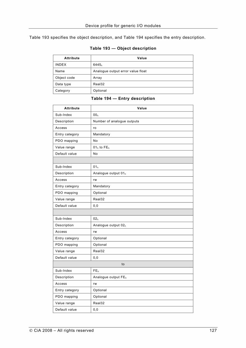
Device profile for generic I/O modules
CiA 2008 – All rights reserved 127
Table 193 specifies the object description, and Table 194 specifies the entry description.
Table 193 — Object description
Attribute Value
INDEX 6445h
Name Analogue output error value float
Object code Array
Data type Real32
Category Optional
Table 194 — Entry description
Attribute Value
Sub-Index 00h
Description Number of analogue outputs
Access ro
Entry category Mandatory
PDO mapping No
Value range 01h to FEh
Default value No
Sub-Index 01h
Description Analogue output 01h
Access rw
Entry category Mandatory
PDO mapping Optional
Value range Real32
Default value 0,0
Sub-Index 02h
Description Analogue output 02h
Access rw
Entry category Optional
PDO mapping Optional
Value range Real32
Default value 0,0
to
Sub-Index FEh
Description Analogue output FEh
Access rw
Entry category Optional
PDO mapping Optional
Value range Real32
Default value 0,0

Device profile for generic I/O modules
128 CiA 2008 – All rights reserved
8.7.9 Object 6446h: Analogue output offset integer
This object shall set the offset in integer format for output data (6413h object).
If the object is not supported, the device shall behave accordingly to 6441h object, or if that object is also not supported, the device shall behave accordingly to the default value.
Configuration of the analogue output offset float object (6441h) shall cause also value change in the 6446h object and vice versa.
Table 195 specifies the object description, and Table 196 specifies the entry description.
Table 195 — Object description
Attribute Value
INDEX 6446h
Name Analogue output offset integer
Object code Array
Data type Integer32
Category Optional
Table 196 — Entry description
Attribute Value
Sub-Index 00h
Description Number of analogue outputs
Access ro
Entry category Mandatory
PDO mapping No
Value range 01h to FEh
Default value No
Sub-Index 01h
Description Analogue output 01h
Access rw
Entry category Mandatory
PDO mapping Optional
Value range Integer32
Default value 0000 0000h
Sub-Index 02h
Description Analogue output 02h
Access rw
Entry category Optional
PDO mapping Optional
Value range Integer32
Default value 0000 0000h
to
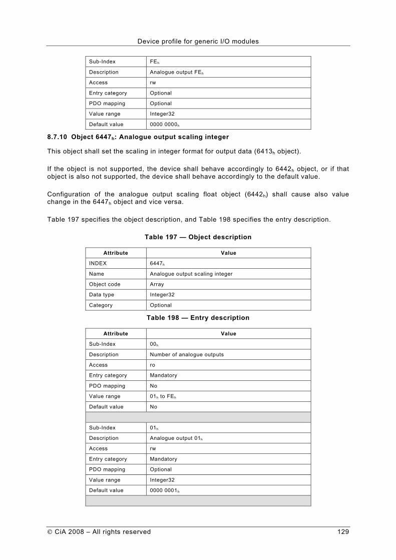
Device profile for generic I/O modules
CiA 2008 – All rights reserved 129
Sub-Index FEh
Description Analogue output FEh
Access rw
Entry category Optional
PDO mapping Optional
Value range Integer32
Default value 0000 0000h
8.7.10 Object 6447h: Analogue output scaling integer
This object shall set the scaling in integer format for output data (6413h object).
If the object is not supported, the device shall behave accordingly to 6442h object, or if that object is also not supported, the device shall behave accordingly to the default value.
Configuration of the analogue output scaling float object (6442h) shall cause also value change in the 6447h object and vice versa.
Table 197 specifies the object description, and Table 198 specifies the entry description.
Table 197 — Object description
Attribute Value
INDEX 6447h
Name Analogue output scaling integer
Object code Array
Data type Integer32
Category Optional
Table 198 — Entry description
Attribute Value
Sub-Index 00h
Description Number of analogue outputs
Access ro
Entry category Mandatory
PDO mapping No
Value range 01h to FEh
Default value No
Sub-Index 01h
Description Analogue output 01h
Access rw
Entry category Mandatory
PDO mapping Optional
Value range Integer32
Default value 0000 0001h

Device profile for generic I/O modules
130 CiA 2008 – All rights reserved
Sub-Index 02h
Description Analogue output 02h
Access rw
Entry category Optional
PDO mapping Optional
Value range Integer32
Default 0000 0001h
to
Sub-Index FEh
Description Analogue output FEh
Access rw
Entry category Optional
PDO mapping Optional
Value range Integer32
Default 0000 0001h
8.7.11 Object 6450h: Analogue output SI unit
This object shall assign SI units and prefixes for analogue outputs. The value structure is defined in Figure 10.
31 24 23 16 15 8 7 0
Prefix SI Numerator SI Denominator reserved
MSB LSB
Figure 10 — Value structure
The values for prefix, SI numerator, and SI denominator are specified in /CiA303-2/.
Table 199 specifies the object description, and Table 200 specifies the entry description.
Table 199 — Object description
Attribute Value
INDEX 6450h
Name Analogue output SI unit
Object code Array
Data type Unsigned32
Category Optional
Table 200 — Entry description
Attribute Value
Sub-Index 00h
Description Number of analogue outputs
Access ro
Entry category Mandatory
PDO mapping No
Value range 01h to FEh
Default value No

Device profile for generic I/O modules
CiA 2008 – All rights reserved 131
Sub-Index 01h
Description Analogue output 01h
Access rw
Entry category Mandatory
PDO mapping Optional
Value range Unsigned32
Default value No
Sub-Index 02h
Description Analogue output 02h
Access rw
Entry category Optional
PDO mapping Optional
Value range Unsigned32
Default value No
to
Sub-Index FEh
Description Analogue output FEh
Access rw
Entry category Optional
PDO mapping Optional
Value range Unsigned32
Default value No
8.8 General device profile objects
8.8.1 Object 67FFh: Device type
This object shall describe the first logical device in a multiple device module according to /CiA301/.

Device profile for generic I/O modules
132 CiA 2008 – All rights reserved
Annex A : Joystick
A.1 Scope
This appendix defines the use of DS-401 for joysticks adopted as a special input module. This input module supports digital inputs and analogue inputs. The digital inputs are the buttons of the joystick and the analogue inputs are the proportional input values. Optional there are digital outputs for indicating LEDs or general purposes.
A.2 Pre-defined communication objects for joysticks
A.2.1 Object 1000h: Device type
The specific functionality is defined as a joystick with digital and analogue inputs. Table 201 specifies the values.
Table 201 — Value definitions
Additional information
Specific functionality
I/O functionality
Device profile number
Description
01h 05h 0191h I/O functionality without digital outputs
01h 07h 0191h I/O functionality with digital outputs
02h 07h 0191h Special PDO mapping for 3-D joystick is used
03h 07h 0191h Special PDO mapping for 2-D joystick is used
A.3 Joystick buttons
The buttons use the functionality for digital inputs with 8-bit access. The 6000h object shall be supported and the related configuration objects may be implemented.
A.4 Joystick proportional inputs
The proportional inputs representing the joystick position use the functionality for analogue inputs with signed 16-bit access. An analogue value of zero represents the zero position of the joystick. The object 6401h shall be supported and all related configuration objects may be implemented.
The default value for the object 6430h (analogue input SI unit) is defined in Figure 11.
31 24 23 16 15 8 7 0
00h 00h 00h 00h
MSB LSB
Figure 11 — Default value for object 6430h
A.5 Joystick PDO mappings
A.5.1 Introduction
The joystick device supports the generic CiA 401 mapping as defined in clause A.5.2 and A.5.3 or the specific joystick mappings as defined in clause A.5.4 and A.5.5.

Device profile for generic I/O modules
CiA 2008 – All rights reserved 133
A.5.2 1st TPDO mapping (buttons)
The first TPDO transmits the values of maximum 8 x 8 buttons. The first 8 buttons (Index 6000h sub-index 01h) are defined in Figure 12. The unused bits may be used manufacturer-specific.
7 0
unused unused unused unused unused memory z-axis
memory y-axis
memory x-axis
MSB LSB
Figure 12 — Structure of object 6000 01h
The memory buttons for x-, y-, and z-axes shall freeze the proportional values of the related axes:
1 = memory function on (freeze proportional values) 0 = memory function off (release proportional values)
NOTE It is optional to include the freezing function into the joystick itself. In this case, the proportional values are not modified any more if the memory function is switched on.
Otherwise freezing is done by the application and the buttons are interpreted as freezing request. In this case, the memory buttons have no effect on the proportional input values.
If the joystick does not support memory function, the bits 0 to 2 shall be 0 and the bits 2 to 7 of the first digital input byte (Object 6000 01h) are used manufacturer-specific.
A.5.3 2nd TPDO mapping (proportional inputs)
The second TPDO transmits the 16-bit values of maximum 4 proportional inputs. The first 3 analogue values (Object 6401 01h to 03h) are used for the three dimensions (x, y, z), the other analogue value is manufacturer-specific.
Figure 13 shows the structure of this TPDO.
63 48 47 32 31 16 15 0
manufacturer-specific z-dimension y-dimension x-dimension
MSB LSB
Figure 13 — Structure of the second TPDO
A.5.4 Specific PDO mapping for 3-D joysticks
If the specific functionality field is 02h, the joystick shall use the first TPDO with the pre-defined mapping as shown in Figure 14.
63 56 55 48 47 32 31 16 15 0
6000 01h 6000 02h z-dimension y-dimension x-dimension
MSB LSB
Figure 14 — Structure of the first TPDO
A.5.5 Specific PDO mapping for 2-D joysticks
If the specific functionality field is 03h, the joystick shall use the first TPDO with the pre-defined mapping as shown in Figure 15.

Device profile for generic I/O modules
134 CiA 2008 – All rights reserved
63 56 55 48 47 40 39 32 31 16 15 0
6000 01h 6000 02h 6000 03h 6000 04h y-dimension x-dimension
MSB LSB
Figure 15 — Structure of the first TPDO
A.6 Joystick signal conditioning
A.6.1 Introduction
The analogue inputs representing the x, y, and z dimension are pre-scaled and offset by using the objects 6432h (642Fh) respectively 6431h (642Eh). If a deadband and post-scaling are required, the objects 6460h (6461h) respectively 6462h (6463h) are used.
A.6.2 Object 6460h: Analogue input dead-band unsigned
This object shall set the dead-band for the analogue inputs (6401 01h to 03h). Figure 16 shows the relationship between the analogue input objects with dead-band-functionality for 16-bit (and 32-bit) access.
6463h
6461h
LEGEND
(1) = up to 16 bit
(2) = Integer32
(3) = Unsigned32
(4) = Integer16
* = left adjusted
CLOSE
IF
TRUE
= 1
XOR
&
AND
6426h
6425h
6424h
6423h
6432h
Upper Limit
Lower Limit
Value Difference
!
<
Interrupt
Enable
Pre-scaling
Single
Analog
Input
6427h
Negative Value
Difference6428
hPositive Value
Difference
642Ch
642Dh
!
ENTRY
into
6401h
{V,A}
(4)* MAP
into
TPDO2 .. 4
1A01 .. 3h
Default
Mapping
Parameter
(1)TRANSMIT
TPDO2 .. 4
{up to 8 Byte} {TPDO1 .. 4}
{E,D}
{T,F}
{T,F}
{T,F}
{T,F}
{T,F}
(2)
(2)
(3)
(3) (3)T = true
F = false
E = enabled
D = disabled
642Bh
1801 .. 3h
Default
Communication
Parameter
Signal
Pre-condi-
tioning
6431h
Offset
A/D
Converter
642Eh
6429h
642Ah
642Fh
6462h
Post-scaling
Signal
Post-condi-
tioning
6460h
Deadband
Deadband
Generator CAN
Trans-
mission
Figure 16 – Analogue Input with dead-band-functionality
Configuration of the analogue input dead-band float object (6461h) shall cause also value change in the 6460h object and vice versa.
Table 202 specifies the object description and Table 203 specifies the entry description.
Table 202 — Object description
Attribute Value
INDEX 6460h
Name Analogue input dead-band unsigned
Object code Array
Data type Unsigned32
Category Optional

Device profile for generic I/O modules
CiA 2008 – All rights reserved 135
Table 203 — Entry description
Attribute Value
Sub-Index 00h
Description Number of analogue inputs
Access ro
Entry category Mandatory
PDO mapping No
Value range 03h
Default value No
Sub-Index 01h
Description Analogue input 01h
Access rw
Entry category Mandatory
PDO mapping Optional
Value range Unsigned32
Default value 0000 0000h
Sub-Index 02h
Description Analogue input 02h
Access rw
Entry category Mandatory
PDO mapping Optional
Value range Unsigned32
Default value 0000 0000h
Sub-Index 03h
Description Analogue input 03h
Access rw
Entry category Mandatory
PDO mapping Optional
Value range Unsigned32
Default value 0000 0000h
A.6.3 Object 6461h: Analogue input dead-band float
This object shall set the dead-band for the analogue inputs (6401 01h to 03h).
Configuration of the analogue input dead-band unsigned object (6460h) shall cause also value change in the 6461h object and vice versa.
Table 204 specifies the object description and Table 205 specifies the entry description.

Device profile for generic I/O modules
136 CiA 2008 – All rights reserved
Table 204 — Object description
Attribute Value
INDEX 642Ah
Name Analogue input dead-band float
Object code Array
Data type Real32
Category Optional
Table 205 — Entry description
Attribute Value
Sub-Index 00h
Description Number analogue inputs
Access ro
Entry category Mandatory
PDO mapping No
Value range 03h
Default value No
Sub-Index 01h
Description Analogue input 01h
Access rw
Entry category Mandatory
PDO mapping Optional
Value range Real32
Default value 0,0
Sub-Index 02h
Description Analogue input 02h
Access rw
Entry category Mandatory
PDO mapping Optional
Value range Real32
Default value 0,0
Sub-Index 03h
Description Analogue input 03h
Access rw
Entry category Mandatory
PDO mapping Optional
Value range Real32
Default value 0,0
A.6.4 Object 6462h: Analogue input post-scaling unsigned
This object shall set the gain after the addition of dead-band-functionality for the analogue inputs (6401 01h to 03h).

Device profile for generic I/O modules
CiA 2008 – All rights reserved 137
Configuration of the analogue input post-scaling float object (6463h) shall cause also value change in the 6462h object and vice versa.
Table 202 specifies the object description and Table 203 specifies the entry description.
Table 206 — Object description
Attribute Value
INDEX 6462h
Name Analogue input post-scaling unsigned
Object code Array
Data type Unsigned32
Category Optional
Table 207 — Entry description
Attribute Value
Sub-Index 00h
Description Number of analogue inputs
Access ro
Entry category Mandatory
PDO mapping No
Value range 01h to 03h
Default value No
Sub-Index 01h
Description Analogue input 01h
Access rw
Entry category Mandatory
PDO mapping Optional
Value range Unsigned32
Default value 0000 0000h
Sub-Index 02h
Description Analogue input 02h
Access rw
Entry category Mandatory
PDO mapping Optional
Value range Unsigned32
Default value 0000 0000h

Device profile for generic I/O modules
138 CiA 2008 – All rights reserved
Sub-Index 03h
Description Analogue input 03h
Access rw
Entry category Mandatory
PDO mapping Optional
Value range Unsigned32
Default value 0000 0000h
A.6.5 Object 6463h: Analogue input post-scaling float
This object shall set the gain after the addition of dead-band-functionality for the analogue inputs (6401 01h to 03h).
Configuration of the analogue input post-scaling unsigned object (6462h) shall cause also value change in the 6463h object and vice versa.
Table 208 specifies the object description and Table 209 specifies the entry description.
Table 208 — Object description
Attribute Value
INDEX 6463h
Name Analogue input post-scaling float
Object code Array
Data type Real32
Category Optional
Table 209 — Entry description
Attribute Value
Sub-Index 00h
Description Number analogue inputs
Access ro
Entry category Mandatory
PDO mapping No
Value range 01h to 03h
Default value No
Sub-Index 01h
Description Analogue input 01h
Access rw
Entry category Mandatory
PDO mapping Optional
Value range Real32
Default value 0,0

Device profile for generic I/O modules
CiA 2008 – All rights reserved 139
Sub-Index 02h
Description Analogue input 02h
Access rw
Entry category Mandatory
PDO mapping Optional
Value range Real32
Default value 0,0
Sub-Index 03h
Description Analogue input 03h
Access rw
Entry category Mandatory
PDO mapping Optional
Value range Real32
Default value 0,0
A.7 Joystick implementation hints
A.7.1 Periodical PDO transmission
If periodical PDO transmission is requested, the event timer is set to ≠ 0.
A.7.2 Additional proportional inputs
If additional proportional inputs are required, the pre-defined 3rd and 4th TPDO are used.
A.7.3 Transmission of proportional inputs
In order to transmit only the first proportional value different from 0, the analogue input set-up objects are used.