canspy: a platform for auditing can devices ecus is fairly new for information security firms and...
TRANSCRIPT

CANSPY: a Platform for Auditing CAN Devices
Arnaud Lebrun
Airbus Defence and Space [email protected]
Jonathan-Christofer Demay
Airbus Defence and Space [email protected]
ABSTRACT
In the past few years, several tools have been released allowing hobbyists to connect to CAN buses found in cars. This is welcomed as the
CAN protocol is becoming the backbone for embedded computers found in smartcars. Its use is now even spreading outside the car through
the OBD-II connector: usage-based policies from insurance companies, air-pollution control from law enforcement or engine diagnostics
from smartphones for instance. Nonetheless, these tools will do no more than what professional tools from automobile manufacturers can
do. In fact, they will do less as they do not have knowledge of upper-layer protocols.
Security auditors are used to dealing with this kind of situation: they reverse-engineer protocols before implementing them on top of their
tool of choice. However, to be efficient at this, they need more than just being able to listen to or interact with what they are auditing.
Precisely, they need to be able to intercept communications and block them, forward them or modify them on the fly. This is why, for
example, a platform such as Burp Suite is popular when it comes to auditing web applications.
In this talk, we present CANSPY, a platform giving security auditors such capabilities when auditing CAN devices. Not only can it block,
forward or modify CAN frames on the fly, it can do so autonomously with a set of rules or interactively using Ethernet and a packet
manipulation framework such as Scapy. It is also worth noting that it was designed to be cheap and easy to build as it is mostly made of
inexpensive COTS. Last but not least, we demonstrate its versatility by turning around a security issue usually considered when it comes to
cars: instead of auditing an electronic control unit (ECU) through the OBD-II connector, we are going to partially emulate ECUs in order to
audit a device that connects to this very connector.
CCS Concepts
• Networks➝Bus networks • Security and privacy➝Embedded systems security • Security and privacy➝Penetration testing.
Keywords
Controller Area Network; Man-in-the-middle attack; Smart vehicle; Security audit.
1. INTRODUCTION
In the past years, the increasing addition of embedded computers in cars known as Electronic Control Unit, or ECU, has improved vehicle
performances as well as safety and comfort for the occupants. As far as the latter point is concerned, it comes along with the need to make
the car connected (i.e., Wi-Fi, Bluetooth, USB or even mobile broadband). As the car’s use of new technologies increases, so does the
attack surface. That much has been proven in the recent years and on numerous occasions by security researchers. As a matter of fact, they
have demonstrated that the worst possible scenario can become reality: a malicious individual remotely endangering the vehicle’s
occupants as well as the nearby vehicles on the road [1]. It is worth noting that, to achieve such result, it is usually needed to go beyond the
compromise of an embedded computer exposed by the attack surface and expand the compromise deeper in the car.
To ensure that such scenarios will not happen outside the laboratories of security researchers, automobile manufacturers have started to
mandate information security firms to conduct audits on current ECUs to assess the risks the vehicle is exposed to and, if need be, craft
remediation plans before damage has already been done. To go farther with this approach, they also mandate audits on prototype ECUs
with the explicit aim of fixing security issues at the earliest possible stage. Regarding the case of prototypes, it is worth mentioning that, not
only it greatly reduces the risk of a vulnerability to ever be present in a commercial vehicle, it is also the most cost-effective approach.
Auditing ECUs is fairly new for information security firms and there is still a great deal of work to be done regarding the methodology and
the tools. Indeed, security auditors are costly resources for automobile manufacturers, meaning that they usually have much less time to
find vulnerabilities than security researchers. On the other hand, unlike security researchers, they work with the assistance of engineers
from the automobile manufacturer. Nonetheless, improving efficiency and thus cost-effectiveness is always at stake for security auditors.
In this paper, we will focus on two aspects: auditing ECUs that are not directly exposed by the attack surface and, more precisely, auditing
them using a penetration testing approach. To that end, after giving an overview of the datalink protocol ECUs use to communicate with
each other, we will go through the penetration testing methodology when applied to this particular case. Then, we will present CANSPY, a
platform providing security auditors with the ability to intercept communications and block them, forward them or modify them on the fly
with standard penetration testing tools. Finally, we will demonstrate the versatility and the efficiency of CANSPY by turning around a
security issue usually considered when it comes to cars: instead of auditing an ECU through the OBD-II connector, we are going to
partially emulate ECUs in order to lay the groundwork needed to audit a device that connects to this very connector.
2. CAN: CONTROLLER AREA NETWORK
The Controller Area Network or CAN is a multi-master serial bus standard initially designed for vehicle applications but is now used in
several other industries (e.g., the aerospace industry). In this section, we will cover the most important aspects of this standard.

2.1 CAN LAYERS The CAN standard specifies the physical and datalink layers of the OSI model. More specifically, ISO 11898-2 and 11898-3 cover the
physical layer respectively for high-speed and low-speed (i.e., fault-tolerant) transmission while ISO 11898-1 covers the datalink layer.
Higher-layer protocols are not covered by ISO 11898 and several other standards haven been designed to address them (e.g., ISO15765-2).
At physical level, communications rely on differential signaling, meaning that electrical transmission is using two complementary signals.
Receiving nodes then measure the difference between the two signals (e.g., ECUs for vehicles, see Figure 1 for illustration). The benefits of
this compared to measuring the difference between a single wire and a ground are robustness against signal noise and fault tolerance. More
specifically, communications relies on balanced differential signaling which means that the flows of both signals are equal but opposite in
direction (i.e., high and low signals). Over a twisted-pair cable, as in the case of the CAN standard, balanced differential signaling enhances
even further the noise-robustness capabilities. Furthermore, additional noise immunity is achieved by maintaining the differential
impedance at low level with 120 ohms resistors at each end of the bus.
Figure 1. Diagram of a single CAN bus
Regarding the datalink layer, let us first focus on the Media Access Control sublayer (MAC). To handle collision issues, it relies on the
CSMA/CR mechanism: Carrier Sense Multiple Access with Collision Resolution. This is a lossless bitwise arbitration method of collision
resolution while transmitting. The key aspects behind this mechanism are the following:
The logical 0 is a dominant bit (i.e., a high voltage state).
The logical 1 is a recessive bit (i.e., a low voltage state).
The idle state is represented by the recessive state (i.e., a logical 1).
Each node always listens to the bus including when it is transmitting.
As a result, if two or more nodes start transmitting at the same time, the collision is resolved by the following behavior:
If all nodes transmit the same bit, dominant or recessive, none of them can detect the collision since the observed voltage state is
the expected one and the transmission thus continues for each one of them.
If one or more nodes transmit a dominant bit while the others transmit a recessive one, the latter will detect the collision as they
listen to the bus and therefore stop transmitting while the former continue with the transmission.
This arbitration continues until there is only one node transmitting on the bus.
All the nodes that lose arbitration wait for the next time the bus is in an idle state to try transmitting again.
In the case of the CAN standard, this arbitration is supposed to be over by the time each node has transmitted the ID, meaning that the
lower the ID is, the better priority the message has. This also means that, within a single CAN bus, every ID must be unique to a type of
messages, a given type of messages can only be transmitted by one particular node and a node can however transmit multiple types of
messages. On that regard, Table 1 and Table 2 provide a complete overview of both base and extended frame formats. To continue with the
CAN frame format, let us now focus on some of the aspects associated with the Logical Link Control sublayer (LLC).
Table 1. The CAN base frame format (source: Wikipedia)
NAME LENGTH (BITS) DESCRIPTION
Start-of-frame 1 Denotes the start of frame transmission.
Identifier 11 A unique identifier which also represents the message priority.
Remote transmission request (RTR) 1 Logical 0 for data frames and logical 1 for remote request frames
Identifier extension bit (IDE) 1 Logical 0 for base frame format with 11-bit identifiers
Reserved bit (r0) 1 Reserved bit
Data length code (DLC) 4 The number of bytes of data
Data field 0-64 The data to be transmitted (length dictated by the DLC field)
CRC 15 Cyclic redundancy check
CRC delimiter 1 Must be recessive (logical 1)
ACK slot 1 A recessive bit (logical 1) for the transmitter
ACK delimiter 1 Must be recessive (logical 1)
End-of-frame (EOF) 7 Must be recessive (logical 1)

Table 2. The CAN extended frame format (source: Wikipedia)
NAME LENGTH (BITS) DESCRIPTION
Start-of-frame 1 Denotes the start of frame transmission
Identifier A 11 First part of the unique identifier which also represents the message priority
Substitute remote request (SRR) 1 Must be recessive (logical 1)
Identifier extension bit (IDE) 1 Logical 1 for extended frame format with 29-bit identifiers
Identifier B 18 Second part of the unique identifier which also represents the message priority
Remote transmission request (RTR) 1 Logical 0 for data frames and logical 1 for remote request frames
Reserved bits (r1, r0) 2 Reserved bits
Data length code (DLC) 4 Number of bytes of data
Data field 0–64 Data to be transmitted (length dictated by the DLC field)
CRC 15 Cyclic redundancy check
CRC delimiter 1 Must be recessive (logical 1)
ACK slot 1 A recessive bit (logical 1) for the transmitter
ACK delimiter 1 Must be recessive (logical 1)
End-of-frame (EOF) 7 Must be recessive (logical 1)
Transmission using data frames is pretty straight forward. The interesting aspect here is the acknowledgment mechanism. It relies on the
ACK slot: while the transmitting node is setting the field with a recessive bit, any other node will overwrite it with a dominant bit if it does
not detect an error. When that occurs, the transmitting node becomes aware that the frame has been properly received by at least one node.
In the opposite situation, the frame is queued again for transmission until proper reception or until a timeout occurs.
Finally, one last aspect deserving a bit of explanation: Remote Transmission Request (RTR) frames. Usually, on a CAN bus, the nodes are
transmitting data frames on their own, leaving it to the other nodes to decide whether or not to process the transmitted data. However, it is
possible for a node to request specific data by using a RTR frame with the proper identifier field. In this situation, the transmitted frame
differs in the following ways:
The RTR field is set with a recessive bit (i.e., a logical 1).
The DLC field now indicates the number of requested bytes.
The data field is empty despite the value of the DLC field.
In case of collision with a data frame with the same identifier, the RTR determines the arbitration (in favor of the data frame).
2.2 CAN ARCHITECTURES The CAN specification does not define the maximum allowed number of nodes. However, depending on the characteristics of the physical
layer and to avoid congestion issues, there is in fact a practical limitation to the number of nodes that should be connected to a single CAN
bus. Nevertheless, modern cars are using an increasing number of ECUs to add new features. For that reason, automobile manufacturers
have been relying on multi-buses architectures. In this section, we present the two main architectures we have encountered in actual audits.
First, we have the architecture that relies on multiple separate buses to distribute the network load (see Figure 2 for illustration).
Nevertheless, in regard to security, this type of architectures could also be considered because of its segmentation capabilities. However,
given the functionalities a modern car is offering, it is almost mandatory that some ECUs will have to be connected to multiple buses. In
case one or more of these ECUs were to be compromised, they could be used to bypass the segmentation.
Figure 2. Diagram of a CAN architecture based on multiple separate buses
Secondly, we have the architecture that relies on multiple interconnected buses (see Figure 3 for illustration). In this case, the network load
is also distributed among several CAN buses but no ECUs are connected to multiple buses except for the one gateway in charge of routing
the frames. It is worth mentioning that routing decisions may be based on static rules but also on the current state of the vehicle (e.g.,

wheel-testing frames are not forwarded if the vehicle is moving). Rightly so, such gateway may also be considered in order to enforce
security along with safety. However, in this case, it becomes a target of choice if another ECU has been compromised beforehand.
Figure 3. Diagram of a CAN architecture based on multiple interconnected buses
3. AUDITING CAN DEVICES
A security audit is methodological approach with an aim at highlighting good security practices as well as vulnerabilities within a given
scope. However, it does not aim at any form of completeness in covering all vulnerabilities. Nonetheless, with the proper methodology, it
should provide the stakeholders with a certain level of confidence in the strength of the asset or group of assets in front of malicious
behaviors at a given point in time. In the remainder of this section, we provide an overview of the specifics of one particular auditing
approach, penetration testing, and an argument about its applicability in the context of CAN devices considering the current available tools.
3.1 PENETRATION TESTS Unlike the conventional approach that relies of reviewing documents (e.g., procedures or schematics), the penetration testing approach
relies on actual tests. The process is simple: an auditor conducts several actions within the given scope and observes the induced behavior.
Then, by analyzing the observed behavior, the auditor tries to infer if the design, the implementation or the configuration of the asset or
group of assets is vulnerable and if there is any room for exploitation. The idea behind such approach is get results rooted in reality by
taking the point of view of real attackers.
However, the relevancy of this approach is tainted by the fact that security auditors have to deal with limitations unknown to real attackers.
Indeed, malicious people are not constrained by deadlines or by ethics considerations. In case of well-funded attackers, they may also have
more resources than the security auditors. For that reason, the penetration testing methodology actually relies on gray-box testing as
opposed to real attackers that are forced to work with a black-box approach.
Indeed, while a black-box tester is not aware of anything about the internals of the considered scope, a gray-box tester has a partial
knowledge of it (e.g., documentations or schematics). This helps leveling the playing field between a security auditor and a real attacker.
Furthermore, such approach can also be used by security auditors to place themselves in the position of a malicious legitimate user or even
in the position of malicious third-party that could get information through a first successful social-engineering attack.
However, gray-box testing is not white-box testing, meaning that the auditors will not be given access to everything, like source codes for
example. Security auditors are used to dealing with this situation: they persist with numerous trials and errors or even reverse-engineer
protocols before implementing them on top of their tool of choice. However, to be efficient at both, they need more than just being able to
listen to or interact with what they are auditing. Precisely, they need to be able to intercept communications and block them, forward them
or modify them on the fly. This is why, for example, a platform such as Burp Suite is popular when it comes to auditing web applications.
3.2 CAN TOOLS In the past years, several tools have been released allowing hobbyists to connect to CAN buses found in cars. This is welcomed as the CAN
protocol is now even spreading outside the car through the OBD-II connector: the more car hacking becomes accessible to tech-savvy
individuals, the better it is for the security community in general. However, these tools will do no more than what professional tools from
automobile manufacturers can do. In fact, they will do less as they do not have knowledge of upper-layer protocols.
Moreover, even though they give users the ability to send and receive frames on and from a CAN bus, they do not provide them with any of
the capabilities exposed in section 3.1. The reason for that is pretty simple: because CAN is a serial bus, it means that in order to achieve
this, you need either to physically cut the bus and insert yourself in-between (see Figure 4 for illustration) or to disconnect a particular ECU
and isolated it on its own bus (see Figure 5 for illustration). Additionally, regarding the former case, CAN buses usually being pretty
congested, it would be mandatory to handle such issue on both sides of the bus (which must now be considered as two separate buses).
Figure 4. Man-in-the-middle setup when physically cutting the CAN bus

Figure 5. Man-in-the-middle setup when isolating a particular ECU
Furthermore, it would not be wise to implement the aforementioned capabilities on top of these existing tools, and for two reasons. First,
they only have one CAN interface. Therefore, to achieve man-in-the-middle capabilities, two devices must be bridged together by a
computer. However, the CAN protocol was designed to meet with timing constraints. It may not be an issue for every ECU but it certainly
would not provide a sound basis for an auditing platform. Secondly, to connect to a computer, they rely on an USB-UART interface
operating at 115.2 kbps. Even though it can be configured to operate at higher rates, even at maximum speed we would be at risks of being
limited. Indeed, keep in mind the objectives behind our approach as well as the requirements derived from them:
Handle two CAN buses at the same time, each one of them being able to go as far as 1Mbit/s.
Provide interoperability using the SocketCAN format which is much less compact than the actual CAN frame format.
Append an additional encapsulation layer to at least be able to distinguish between the two CAN interfaces.
Reduce the latency as much as possible in order to meet with the timing constraints of the CAN protocol.
Never drop any CAN frame as this would prevent the proper processing of fragmented payloads.
For that reason, we argue that the best choice is the use of an Ethernet controller:
The chance of having congestion issues with our case is inexistent.
It has been available as standard on any computer for several decades.
MAC addresses can be used to distinguish between the two CAN interfaces.
Data transfer rates will in fact provide very low latencies.
Regarding the no-frame-drop requirement, it is not only about the connectivity with the host computer but also about the speed of the actual
processing. This is why we should dismiss popular hardware platform like Arduino and instead turn to more powerful microcontrollers.
Nonetheless, there is another reason why we argue that Ethernet would be the best choice: it allows out-of-the-box use of existing packet
manipulation frameworks such as Scapy [5]. Not only will this provide security auditors with the ability to use mature and efficient tools, it
will also help join efforts when it comes to reverse-engineering higher-layer protocols. It was our position with Scapy-radio [2] regarding
the case of radio-communication protocols and it showed its effectiveness in distributing the workload among security specialists.
4. CANSPY ARCHITECTURE In this section, we detail the architecture of the platform we designed to meet with the functional specifications expressed in section 3.
4.1 CANSPY HARDWARE The main board of CANSPY is a STM32F4DISCOVERY from STMicroelectronics (see Figure 6). It relies on a STM32F407VGT6
microcontroller with an ARM Cortex-M4 32-bit core running at 160 MHz. This microcontroller also provides several additional cores such
as 10/100 Ethernet, Micro SD card, UART and CAN. There are more cores other than those we have just listed but these are what we
required to build CANSPY.
More specifically, two distinct CAN cores were required and this is precisely what this board provides. Additionally, having these CAN
cores also avoids the use of SPI buses. Yet, none of the transceivers and connectors required to use the aforementioned cores are provided
by this board. That is why we attached to this board the STM32F4DIS-BB extension board (see Figure 7). It provides transceivers and
connectors for 10/100 Ethernet, Micro SD card and UART in the form of RS232 with a DB9 connector.
Figure 6. Picture of the STM32F4DISCOVERY board
Figure 7. Picture of the STM32F4DIS-BB extension board

However, this extension board does not provide any transceivers or connectors for CAN connectivity. That is why we designed an
additional extension board (see Figure 8). The CANSPY extension board provides connectivity for the two CAN cores (from now on
designated as CAN1 and CAN2) as well as several possible configurations using jumpers (details are given later in this section). It relies on
a simple design with few components which makes it easy and cheap to build. It is worth mentioning that the CANSPY extension board
provides DB9 connectors and their routing is identical to the one chosen by Goodthopter [2]. This means that any cable compatible with
Goodthopter will be compatible with CANSPY. As whole, the CANSPY hardware platform is inexpensive and easy to put together.
Figure 8. Picture of the CANSPY extension board (v1.2)
Figure 9. Picture of the unpopulated PCB of the CANSPY
extension board (v1.3)
As mentioned above, the CANSPY extension board allows several possible configurations using jumpers. This is a direct consequence of
the different issues we exposed in sections 2 and 3. It is worth noting that we are also considering the OBD-II case which provides a 12-
volt line. We explain these configurations here using a picture of an unpopulated PCB of the CANSPY extension board (see Figure 9):
P104, P105, P106 and P107 provide a direct access to the high and low lines of CAN1 and CAN2. Shunting them will thus
merge CAN1 and CAN2 which might be used to hot-unplug CANSPY (i.e., without unplugging the DB9 cables). The use of
jumper wires is required when DB9 cables are not available in a given situation. The reason why there is twice the number of
jumper pins is because it is convenient when building a CAN testbed using only CANSPY devices.
P001 and P102, if shunted, provide respectively for CAN1 and CAN2 the 120 Ohm resistor needed at the end of a CAN bus. Do
not shunt these pins if the resistor is already present on the bus you are connecting to. Otherwise, it might damage the CAN
devices that are also connected to this bus. Usually, you only need to shunt these pins when building a CAN testbed.
P100, if shunted, connects the 12-volt line between CAN1 and CAN2. This is needed when the power source for the CAN
transceivers in U000 and U100 is the 12-volt line via the voltage regulator in U101.
P103, if shunted, connects the 5 V line between the main board and CAN1. This is needed when both the main board and the
CAN transceivers in U000 and U100 are using the same power source, whether it is the 12-volt line via the voltage regulator in
U101 or the 5 V line (e.g., the USB cable). Do not shunt it if both power sources are present.
Additionally, when building a CAN testbed, providing the 12-volt line might be necessary (e.g., a CAN device is powered by this
line). In that regard and for practical reasons, the red square in Figure 9 is the location of an electrical terminal connected to the
12-volt line. Moreover, devices powered by the 12-volt line might use the “signal ground” instead of the “chassis ground”. In that
situation, shunt P201 to connect both grounds. Do not shunt it when connected to a car.
4.2 CANSPY FIRMWARE In this section, we present the firmware we developed to run on the hardware platform previously exposed. First and foremost, Figure 10 in
the next page shows the overall architecture. At the lowest levels, we have the different device drivers and the hardware abstraction layer
provided by the STM32CubeF4 SDK from STMicroelectronics [4]. At the highest levels we have the scheduling mechanisms and in-
between we have the different device handlers and services.
Each service is registered to a particular device and handles a single job. Only the registered services of a given device can use this device
to transmit data. Conversely, the data received by any device is accessible to all services. This is achieved using respectively exclusive and
shared buffers. This functional segmentation helps enforcing the single-job service approach but also provides the user with the mean to
disable transmission for a given device without disabling reception.
4.2.1 CANSPY SCHEDULING Before digging into the details of the device handlers and their services, let us first focus on the scheduling mechanism. First of all, the fact
is that we must be able to handle multiple I/O devices at the same time, on a single core, while meeting the timing constraints of two
distinct CAN buses. Interrupt-driven I/O handling is a proven approach in such situation and the hardware abstraction layer is appropriately
providing us with an interrupt mode of operation. Consequently, regarding the I/O operations of the CAN devices, given that the frequency
of the microcontroller is high enough compared to the bitrate of the CAN buses, we should not face any timing issues.
Furthermore, all other possible I/O operations are also bounded by the bitrate of the CAN buses: whether it is with the Ethernet controller
or with the Micro SD card drive, all I/O operations are about reading or writing CAN frames. It is worth mentioning that CAN frames have
a maximum size of 128 bits (including the PHY layer). This means that, with services designed to handle one interrupt at a time and to
process CAN frames with a linear time-complexity, we thus have a constant upper bound to how long any service will take to complete its
current job. The only exceptions to this are the debugging and configuration services. Therefore, in the remainder of this section, such
services will not be considered when explaining the choice we made to meet with timing constraints.

Because of the very nature of the objectives of the CANSPY platform, there are no interrupt-handling services (i.e., synchronous services)
more important than others. Indeed, for example, in case of a man-in-the-middle setup where we want to monitor the CAN traffic, the
service transmitting a received frame on the destination CAN bus is no more important than the one transmitting that very frame on the
Ethernet network. For that reason and the fact that each service has a bounded execution time, the scheduling mechanism for synchronous
services relies on a flag-based cyclic executive loop, thus saving the cost of a context-switching mechanism.
However, in order to also have the ability to include services that are not triggered by an interrupt but instead run permanently (i.e.,
asynchronous services), a distinct cyclic executive loop is dedicated to this type of services. To ensure that the synchronous services have
an absolute priority over the asynchronous ones, a priority scheduler is placed on top of both cyclic executive loops. This is a non-
preemptive scheduler, meaning it cannot interrupt a service but only a loop after the current service has returned. Again, with asynchronous
services also designed to have a bounded execution time, adding a context-switching mechanism would not have been cost-effective.
Finally, there still might be situations where several services registered to a particular device can conflict with each other. For example, in
case where a service is filtering frames between the two CAN buses while another one is blindly forwarding them (i.e., the former thus
being completely undermined by the latter). To handle these situations, a mutual exclusion mechanism is also present: each service can be
registered with an exclusive write access to the device it is registered to. When two or more of such services are started for a given device,
the one considered by the cyclic executive loop is the one that was first registered. As a result, the following behavior will happen: for a
given device and at the same time, any number of non-mutually-exclusive services can run but only one mutually-exclusive service at most.
Figure 10. CANSPY firmware architecture
4.2.2 CANSPY DEVICES In this section, we described all the device handlers implemented by CANSPY as well as their respective options. As previously stated, the
STM32F407VGT6 microcontroller is providing two distinct CAN cores. In the remainder of this section, there are referred to as CAN1 and
CAN2. Having two distinct CAN interfaces was mandatory to properly implement man-in-the-middle capabilities. Consequently, every
options and services are duplicated for each CAN device handler in order to make them fully independent. The idea behind this
independency is to not restrict users on how they can process CAN frames. For example, it is possible to forward frames from CAN1 to
CAN2 while blocking them the other way around, thus creating a CAN diode.
Each one of the CAN device handlers is supporting the following options:
can_spd: the speed of the CAN bus (it can differ for both devices, thus allowing the use of two different buses at the same time).
can_mac: the MAC address of the CAN interface over Ethernet (the default last byte is the ID of the CAN interface).
can_typ: the Ethertype used for CAN encapsulation (the local experimental value 0x88b5 allowed by RFC7042 is the default).
can_sil: specifies if a CAN interface is silent (i.e., no acknowledgement) until the transmission on the other one has occurred.
High-priority cyclic executive for synchronous services
Low-priority cyclic executive for asynchronous services
Non-preemptive priority scheduler
Service
Service
Service
Device handler
Service
Service
Service
Device handler
Service
Service
Service
Device handler
Device driver
Transmit buffer Transmit buffer Transmit buffer
Device driver Device driver
Hardware Abstraction Layer
Receive buffer Receive buffer Receive buffer
Mutex Mutex Mutex

It is worth explaining that the last option exists for throttling purposes and why we need this. CAN buses can be pretty congested, meaning
that CAN devices will be naturally throttled by the congestion and that the ID-based priority management mechanism will be essential in
order for all messages to meet their deadlines. However, if we use CANSPY to separate a device from its CAN bus (see Figure 5 in section
3.2 for a diagram of this situation), depending on the filtering rules, this device may have a less congested bus dedicated to itself, thus
gaining the ability to transmit more frames that we can forward. Temporarily making CANSPY silent on the bus dedicated to the isolated
device (i.e., no acknowledgement) will prevent that device from sending new CAN frames until the last received one has been properly
forwarded on the other bus. It is also worth noting that this option is registered at handler level so that this throttling mechanism can be
used by multiple services (i.e., forward and filter services).
The device handler dedicated to the UART device only has one option, uart_dbg. It specifies the level of debug messages that should be
printed on the UART console (by default, boot and fatal messages are printed). Similarly, the Ethernet device handler is pretty simple as
most of the options are configurable at service level. Nonetheless, the following options are supported:
eth_mac: the MAC address of the CANSPY device itself (different from the ones used for the CAN devices).
eth_dbg: specifies the level of debug messages that should be sent over Ethernet (by default, boot and fatal messages are sent).
Regarding this last option, it is worth mentioning that an additional objective of the CANSPY platform is to be totally operable, including
debugging and configuration features, over Ethernet (i.e., without the need to use the UART connectivity). As for the SDCARD device, it
does not have any options since all the available ones are configurable at service level.
4.2.3 CANSPY SERVICES In this section, we described the services registered to every CANSPY devices as well as their respective options. First and foremost, as
previously stated, there is one instance of every CAN services for each of the two CAN device handlers. There are listed hereafter with
their respective options:
inject: frame injection from outside the CAN devices.
filter: traffic filtering based on locally-stored rules.
flt_rul: the list of rules to use to filter CAN frames.
flt_def: the default action (rule 0) for CAN frames when no defined rules matches.
flt_dmy: specifies if a dummy frame should be sent when dropping a frame from the CAN interface.
forward: traffic forwarding (completely bypass the filtering engine).
It is worth mentioning that inject services exist because of the functional segmentation explained in section 4.2. Indeed, since services
cannot transmit data using a device they are not registered to, they need to request transmission to another service from that device. This is
achieved using a simple inter-service communication mechanism. Furthermore, in this particular case, disabling the inject service for a
given CAN device provides the user with the guarantee that no injection from other devices can happen unintentionally.
Another thing worth explaining is the flt_dmy option. In section 4.2.2, we explained that there are cases when a man-in-the-middle setup
can impact congestion on the CAN buses and thus put us in a situation where we are forced to drop frames. Precisely, this might happen
when using a filter service: if it drops a frame from the source bus instead of forwarding it, this increases the bandwidth on the destination
bus, thus putting us in a situation where we might not be able to forward all the traffic the other way around. The idea behind the flt_dmy
option is, instead of dropping the frame, it may be better to replace it with a dummy frame (i.e., padded with zeros) of the same priority.
After the CAN services, the Ethernet services are the most important services regarding the man-in-the-middle capabilities. There are
listed hereafter with their respective options:
wiretap: send the whole CAN traffic to the host computer (SocketCAN encapsulation).
bridge: perform network bridging with the CAN buses (wiretapping and injection to and from the host computer).
bri_ack: specifies, if needed, how to acknowledge the injection of CAN frame.
command: shell execution from the host computer.
cmd_typ: the Ethertype used for commands (the local experimental value 0x88b6 allowed by RFC7042 is the default).
cmd_out: specifies if commands received over Ethernet should return their output.
That last service is here to fulfill an objective already exposed in this section: making the CANSPY platform operable, including debugging
and configuration features, over Ethernet (i.e., without the need to use the UART connectivity). It is absolutely necessary that this service
relies on an Ethertype different than the one used to encapsulate CAN frames (cf. the can_typ options). Let us now focus on SDCARD
services and their respective options:
capture: dump the whole traffic in a PCAP file.
cap_pre: the prefix used to create a capture file.
cap_inj: specifies whether to capture injected frames.
cap_fil: specifies when to capture a frame based on filtering rules.
logging: write all events in a log file.
log_pre: the prefix used to create the log file.
log_dbg: specifies the level of debug messages that should be logged (by default, all messages are logged)

replay: generate traffic from a PCAP file.
rep_fil: the PCAP file to replay.
rep_can: the CAN interfaces on which to replay frames (by default, the MAC addresses are used).
rep_inf: specifies whether to replay indefinitely (repeat loop).
It should be mentioned that behind the SDCARD services, there is another additional objective of the CANSPY platform: to be fully
functional without a host computer connected to it. In section 4.1, we explained that it can be powered by the 12-volt line of a car. If, in
addition to this, a Micro SD card is plugged into the STM32F4DIS-BB extension board, then the CANSPY platform has the ability to
monitor, inject and alter CAN traffic autonomously. Finally, even though they were primarily designed with debugging purposes in mind
(they do not have any options), let us have a look at UART services and especially at the shell service:
print: synchronous printing (optional).
monitor: print the whole traffic in the console.
viewing: print all events in the console.
shell: an interactive shell providing the following commands:
help: display help for commands
stats: display information about the platform
device: display or change device status
service: display or change service status
option: display or change service/device options
filter: display or change filtering rules
inject: inject frames on a CAN bus
ls: list the content of directories
rm: remove files or empty directories
mv: move files or directories
cd: change the current directory
pwd: print the current/working directory
cat: concatenate and print files
xxd: print the hexadecimal dump of a file
pcap: print a capture file (PCAP format)
mkdir: create new directories
rmdir: remove non-empty directories
One last thing worth mentioning that concerns the print service. In section 4.2.1, we presented the scheduling mechanism we designed in
order to meet with the timing constraints required by the objectives of the CANSPY platform. However, we also stated that the debugging
and configuration features (mainly UART services) were explicitly allowed to not meet with these constraints. In case the user really needs
to not impair timings while still having a constant and heavy use of the UART console, enabling the print service do the job. Consequently,
it will limit the amount of bytes that can be printed on the UART console which might also limits debugging capabilities.
4.2.4 CANSPY FILTERING With the CANSPY platform, there are two approaches to filter CAN frames in a man-in-the-middle setup. The first one uses the host
computer: disable forward and filter services, enable inject and bridge services, then it is up to the user to decide whether or not to send
back the received CAN frames, altered or not, using its favorite packet manipulation framework (we provide the layers for Scapy [5]).
The second approach uses the internal filtering capabilities of the CANSPY platform. These capabilities rely on a simple pattern-matching
mechanism for each field of the CAN frame format (see section 2 for details). A set of patterns is then associated with an action that might
include altering operations. A filtering rule typical looks like this:
IF: [CAN1|CAN2] ID: [=|>|<|!][UINT] TYPE: [RTR|DATA] SIZE: [=|>|<|!][UINT] DATA: [BEG|END|CON|EQU|REG]:[C-LIKE ESCAPE SEQUENCE|REGULAR EXPRESSION] ACTION: [DROP|FWRD|ALTR] CHANGE: [C-LIKE ESCAPE SEQUENCE]
It is worth mentioning that the keyword ANY can be used to indicate that no matching operation are to be conduct on a particular field. Let
us now have a focus matching mechanism for the CAN payload. Hereafter is the meaning the keywords given hereinabove:
BEG: data must begin with the specified C-like sequence.
END: data must end with the specified C-like sequence.
CON: data must contain the specified C-like sequence.
EQU: data must equal the specified C-like sequence.
REG: data must match the specified regular expression.
Let us also do this for the action keywords:
FWRD: matched frames will be forwarded.
DROP: matched frames will be dropped.
ALTR: matched frames will be altered with the specified changes then forwarded.

Finally, do make this even clearer, hereafter are several examples:
# Forward CAN1 frames with an ID higher than 130 when they end with 0x44,0x45 # after replacing these 2 bytes by the only byte 0x42 (thus decreasing the frame size by 1) Filter add CAN1 >130 DATA ANY END:"\x44\x45" ALTR "\x42" # Forward ANY frames when they start and end respectively with 0x44 and 0x45 # after replacing these 2 bytes respectively with 0x34 and 0x35 Filter add ANY ANY DATA ANY REG:"^(\x44).*(\x45)$" ALTR "\x34" "\x35" # Drop all RTR frame Filter add ANY ANY RTR ANY ANY DROP
One last thing worth mentioning about the way regular expressions are processed internally. First and foremost, the CANSPY firmware
relies on the SRLE library [6]. We encourage you to have a look at the supported syntax when crafting filtering rules based on regular
expressions. Furthermore, the possibility to use regular expressions is overlapping with the other keywords which thus may seem
redundant. Remember that we want to have a constant upper bound to how long any service will take to complete its current job (see
section 4.2.1 for details). This is not something that we can guarantee with regular expressions, hence the other keywords which should be
given an absolute priority over regular expressions. In the general case, always be careful with regular expressions and make sure the total
number of rules does not induce frame dropping.
5. APPLICATION ON OBD-II
In section 3.2, we explained that, in order to set up a man-in-the-middle configuration, it is mandatory to either physically cut the bus or to
unplug a particular ECU. However, from the point of view of security auditors, this is not something difficult to achieve. Indeed, as stated
in section 3.1, auditors rely on gray-box testing, meaning that the automobile manufacturer is providing them with assistance. As such, they
can for example request access to the integration bench the automobile manufacturer is using for validation. If that is not possible, they can
instead ask for input specifications in order to build their own testbed.
However, there is one case where anyone can easily set up a man-in-the-middle configuration or build a custom testbed: On-Board
Diagnostics or OBD. This term describes the vehicle self-diagnostic and reporting capabilities offered to automotive technicians in order to
access to the status of the various ECUs. Furthermore, the OBD-II standard, allowing five signaling protocols including CAN, has been
mandatory for all cars for two decades now. More recently, the CAN protocol has become mandatory in itself. Any car that is more-or-less
modern will thus expose a CAN interface in the cabin of the vehicle.
In the remainder of this section, in order to demonstrate the versatility and the efficiency of the CANSPY platform, we will focus on this
specific use case: auditing automotive diagnostic software, first by intercepting and modifying CAN frames while connected to an actual
car, then by partially simulating the car on a custom testbed. Indeed, there are an increasing number of OBD-II devices and we argue that,
if compromised, they might expose the other cars these devices will be connected to [7] and potentially the infrastructure they interconnect
with. It is important to highlight that the purpose of this section is not to release vulnerabilities on any diagnostic software but to lay the
groundwork needed to audit a device that connects to an OBD-II connector.
ELM327 is a programmed microcontroller that provides an abstraction layer with the OBD-II protocols. It is used by numerous OBD-II
adapters that are compatible with most consumer-grade diagnostic tools, including those that are available on smartphones. The work that
follows has been conducted on our own cars using such set of adapters and software.
First, to set up the man-in-the-middle configuration on one of our cars, we had to build a DB9 cable with a routing identical to the one used
by the Goodthopter [3] but with a female OBD-II connector on the other end. Once this was done, all that was left to do was to plug a
CANSPY device in-between the car and the ELM327 cable and to start the forward and the wiretap services (see section 4.2.3 for details).
To easily dissect the captured CAN frames and visualize the whole traffic, it is possible to use Wireshark as it natively supports the
SocketCAN format. All that is needed to achieve this is to associate the SocketCAN dissector with the Ethertype 0x88b5. As shown by
Code 1, a simple Lua script can do this with just a few lines.
Code 1. Lua script associating the SocketCAN dissector with the Ethertype 0x88b5 in Wireshark
At this point, it is easy to see that the CAN frames are complying with the ISO 15765-2 standard (ISO-TP) for the network and transport
layers and with the SAE J1939 standard for the codes used to request data from ECUs. This result was very much expected as this is now
the standard on any recent car. Nonetheless, this is an opportunity to demonstrate the filtering engine of the CANSPY platform. Based on
the OBD PIDs defined by the SAE J1939 standard [8], the vehicle speed should be provided by the PID 0x0d in the mode 0x01 of
operations and stored on 1 byte. Considering the header of the ISO-TP layer, a message containing the vehicle speed should have the
following form: \x03\x41\x0d\x??\x00\x00\x00\x00. To drive at 255km/h, at least according to the diagnostic software shown in Figure 11,
the following rule is given to the CANSPY filtering engine: ANY >0x7DE DATA 8 REG:"^\x03\x41\x0d(.)" ALTR "\xff". Needless to
say, under no circumstances our city car could ever drive that fast. That also raises a question: what about car that can drive faster than
255km/h? Finally, this example also shows that the internal filtering engine only works on a single CAN frame at a time and thus does not
account for fragmented payload. This is something we might consider supporting in the near future (i.e., for now, do this over Ethernet).
--wireshark -X lua_script:EtherCAN.lua local sll_tab = DissectorTable.get("sll.ltype") local can_hdl = sll_tab:get_dissector(0x000C) local eth_tab = DissectorTable.get("ethertype") eth_tab:add(0x88b5, can_hdl)
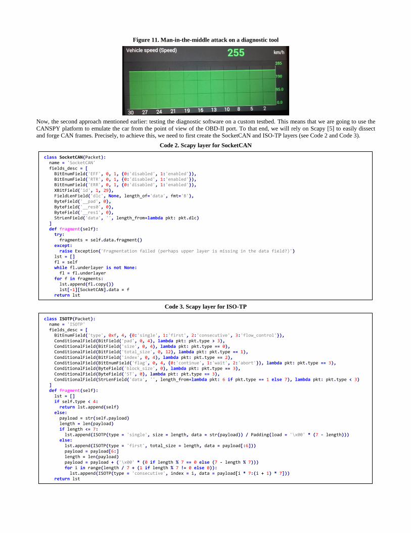
Figure 11. Man-in-the-middle attack on a diagnostic tool
Now, the second approach mentioned earlier: testing the diagnostic software on a custom testbed. This means that we are going to use the
CANSPY platform to emulate the car from the point of view of the OBD-II port. To that end, we will rely on Scapy [5] to easily dissect
and forge CAN frames. Precisely, to achieve this, we need to first create the SocketCAN and ISO-TP layers (see Code 2 and Code 3).
Code 2. Scapy layer for SocketCAN
Code 3. Scapy layer for ISO-TP
class ISOTP(Packet): name = 'ISOTP' fields_desc = [ BitEnumField('type', 0xf, 4, {0:'single', 1:'first', 2:'consecutive', 3:'flow_control'}), ConditionalField(BitField('pad', 0, 4), lambda pkt: pkt.type > 3), ConditionalField(BitField('size', 0, 4), lambda pkt: pkt.type == 0), ConditionalField(BitField('total_size', 0, 12), lambda pkt: pkt.type == 1), ConditionalField(BitField('index', 0, 4), lambda pkt: pkt.type == 2), ConditionalField(BitEnumField('flag', 0, 4, {0:'continue', 1:'wait', 2:'abort'}), lambda pkt: pkt.type == 3), ConditionalField(ByteField('block_size', 0), lambda pkt: pkt.type == 3), ConditionalField(ByteField('ST', 0), lambda pkt: pkt.type == 3), ConditionalField(StrLenField('data', '', length_from=lambda pkt: 6 if pkt.type == 1 else 7), lambda pkt: pkt.type < 3) ] def fragment(self): lst = [] if self.type < 4: return lst.append(self) else: payload = str(self.payload) length = len(payload) if length <= 7: lst.append(ISOTP(type = 'single', size = length, data = str(payload)) / Padding(load = '\x00' * (7 - length))) else: lst.append(ISOTP(type = 'first', total_size = length, data = payload[:6])) payload = payload[6:] length = len(payload) payload = payload + ('\x00' * (0 if length % 7 == 0 else (7 - length % 7))) for i in range(length / 7 + (1 if length % 7 != 0 else 0)): lst.append(ISOTP(type = 'consecutive', index = i, data = payload[i * 7:(i + 1) * 7])) return lst
class SocketCAN(Packet): name = 'SocketCAN' fields_desc = [ BitEnumField('EFF', 0, 1, {0:'disabled', 1:'enabled'}), BitEnumField('RTR', 0, 1, {0:'disabled', 1:'enabled'}), BitEnumField('ERR', 0, 1, {0:'disabled', 1:'enabled'}), XBitField('id', 1, 29), FieldLenField('dlc', None, length_of='data', fmt='B'), ByteField('__pad', 0), ByteField('__res0', 0), ByteField('__res1', 0), StrLenField('data', '', length_from=lambda pkt: pkt.dlc) ] def fragment(self): try: fragments = self.data.fragment() except: raise Exception('Fragmentation failed (perhaps upper layer is missing in the data field?)') lst = [] fl = self while fl.underlayer is not None: fl = fl.underlayer for f in fragments: lst.append(fl.copy()) lst[-1][SocketCAN].data = f return lst
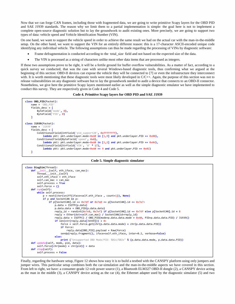
Now that we can forge CAN frames, including those with fragmented data, we are going to write primitive Scapy layers for the OBD PID
and SAE J1939 standards. The reason why we limit them to a partial implementation is simple: the goal here is not to implement a
complete open-source diagnostic solution but to lay the groundwork to audit existing ones. More precisely, we are going to support two
types of data: vehicle speed and Vehicle Identification Number (VIN).
On one hand, we want to support the vehicle speed in order to achieve the same result we had on the actual car with the man-in-the-middle
setup. On the other hand, we want to support the VIN for an entirely different reason: this is a 17-character ASCII-encoded unique code
identifying any individual vehicle. The following assumptions can thus be made regarding the processing of VINs by diagnostic software:
Frame defragmentation is conducted according to the ‘total_size’ field and not based on the expected size of the data.
The VIN is processed as a string of characters unlike most other data items that are processed as integers.
If these two assumptions prove to be right, it will be a fertile ground for buffer overflow vulnerabilities. As a matter of fact, according to a
quick survey we conducted, that was the case with several Windows-based diagnostic tools, thus confirming what we argued at the
beginning of this section: OBD-II devices can expose the vehicle they will be connected to [7] or even the infrastructure they interconnect
with. It is worth mentioning that these diagnostic tools were most likely developed in C/C++. Again, the purpose of this section was not to
release vulnerabilities on any diagnostic software but to lay the groundwork needed to audit a device that connects to an OBD-II connector.
Nonetheless, we give here the primitive Scapy layers mentioned earlier as well as the simple diagnostic emulator we have implemented to
conduct this survey. They are respectively given in Code 4 and Code 5.
Code 4. Primitive Scapy layers for OBD PID and SAE J1939
Code 5. Simple diagnostic simulator
Finally, regarding the hardware setup, Figure 12 shows how easy it is to build a testbed with the CANSPY platform using only jumpers and
jumper wires. This particular setup combines both the car-simulation and the man-in-the-middle aspects we have covered in this section.
From left to right, we have: a consumer-grade 12-volt power source (1), a Bluetooth ELM327 OBD-II dongle (2), a CANSPY device acting
as the man in the middle (3), a CANSPY device acting as the car (4), the Ethernet adapter used by the diagnostic simulator (5) and two
class DiagSim(Thread): def __init__(self, eth_iface, can_mac): Thread.__init__(self) self.eth_iface = eth_iface self.can_mac = can_mac self.process = True self.force = {} def run(self): while self.process: p = next(iter(sniff(iface=self.eth_iface , count=1)), None) if p and SocketCAN in p: if p[SocketCAN].id == 0x7df or 0x7e0 <= p[SocketCAN].id <= 0x7e7: p.data = ISOTP(p.data) p.data.data = OBD_PID(p.data.data) reply_id = randint(0x7e8, 0x7ef) if p[SocketCAN].id == 0x7df else p[SocketCAN].id + 8 reply = Ether(dst=self.can_mac) / SocketCAN(id=reply_id) reply.data = ISOTP() / OBD_PID(mode=p.data.data.mode + 0x40, PID=p.data.data.PID) / J1939() if len(str(reply.data[J1939])) > 0: force = self.force.get(chr(p.data.data.mode) + chr(p.data.data.PID)) if force: reply.data[OBD_PID].payload = Raw(force) sendp(reply.fragment(), iface=self.eth_iface, inter=0.2, verbose=False) else: print ("Unsupported OBD Mode/PID: %02x/%02x" % (p.data.data.mode, p.data.data.PID)) def update(self, mode, pid, data): self.force[chr(mode) + chr(pid)] = data def stop(self): self.process = False
class OBD_PID(Packet): name = 'OBD_PID' fields_desc = [ ByteField('mode', 0), ByteField('PID', 0) ] class J1939(Packet): name = 'J1939' fields_desc = [ ConditionalField(IntField('pid_support20', 0xffffffff), lambda pkt: pkt.underlayer.mode-0x40 in [1,9] and pkt.underlayer.PID == 0x00), ConditionalField(ByteField('speed', 0x0), lambda pkt: pkt.underlayer.mode-0x40 in [1,2] and pkt.underlayer.PID == 0x0d), ConditionalField(StrField('VIN', '0' * 17), lambda pkt: pkt.underlayer.mode-0x40 == 9 and pkt.underlayer.PID == 0x02) ]

UART adapters for monitoring and debugging purposes (6). It is worth mentioning that this testbed use CANSPY extension boards version
1.2 and that fewer jumper wires would be needed with version 1.3. Regarding the potential need for an external 12-volt power source,
version 1.3 of the CANSPY extension board is also providing an electrical terminal on the left of the CAN1 DB9 port to avoid wiring
mistakes that could damage the device (see section 4.1 for details).
Figure 12. A complete testbed based on CANSPY devices (picture on the left and diagram on the right)
6. CONCLUSION
In this paper, after covering the most important aspects of the CAN protocol, we have explained how the standard penetration methodology
applies when auditing ECUs that are not directly exposed by the attack surface. Then, we have presented CANSPY, a platform giving
security auditors the ability to block, forward or modify CAN frames on the fly, autonomously with a set of rules or interactively using
Ethernet and a packet manipulation framework such as Scapy. In this regard, we have also detailed both the hardware and the firmware
designs as well as all the options that we have implemented in order to cover all possible situations, including the complex situation when
the congestion on a CAN bus must not be tampered with.
Finally, in order to demonstrate the versatility and the efficiency of the CANSPY platform, we turned around a security issue usually
considered when it comes to cars: instead of auditing an ECU through the OBD-II connector, we have detailed how the CANSPY platform
can be used to partially emulate ECUs in order to lay the groundwork needed to audit a device that connects to this very connector. On this
subject, we have also demonstrated how easy it is to build a CAN testbed using only CANSPY devices and jumper wires.
As for future work, the internal filtering engine is critical to manipulate CAN frames destined to ECUs that have low tolerance regarding
timing constraints. As of now, its filtering capabilities are limited to a single CAN frame at a time without even considering the possible
fragmentation of the data. Adding defragmentation capabilities to the internal filtering engine is next on our to-do list.
7. CODE RELEASE
The CANSPY project is open-source and can be acquired here: https://bitbucket.org/jcdemay/canspy. The internal filtering engine uses
code from the SRLE library [6] and from the GNU Core utilities [9], respectively licensed under the GNU General Public License version
2 and version 3. All other parts of the firmware are licensed under the BSD 3-Clause license.
8. REFERENCES
[1] https://www.wired.com/2015/07/hackers-remotely-kill-jeep-highway/
[2] https://www.blackhat.com/docs/us-14/materials/us-14-Picod-Bringing-Software-Defined-Radio-To-The-Penetration-Testing-Community-WP.pdf
[3] http://goodfet.sourceforge.net/hardware/goodthopter12/
[4] http://www.st.com/resource/en/data_brief/stm32cubef4.pdf
[5] http://secdev.org/projects/scapy
[6] https://docs.cesanta.com/slre/
[7] http://blog.crysys.hu/2015/10/hacking-cars-in-the-style-of-stuxnet/
[8] https://en.wikipedia.org/wiki/OBD-II_PIDs
[9] http://www.gnu.org/software/coreutils/coreutils.html
1
2
3
4
5
6