capacity at intersection
TRANSCRIPT
Presented by Ruokuomenuo Rio
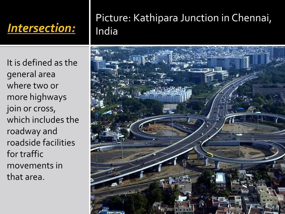
Intersection:
It is defined as the general area where two or more highways join or cross, which includes the roadway and roadside facilities for traffic movements in that area.
Picture: Kathipara Junction in Chennai, India
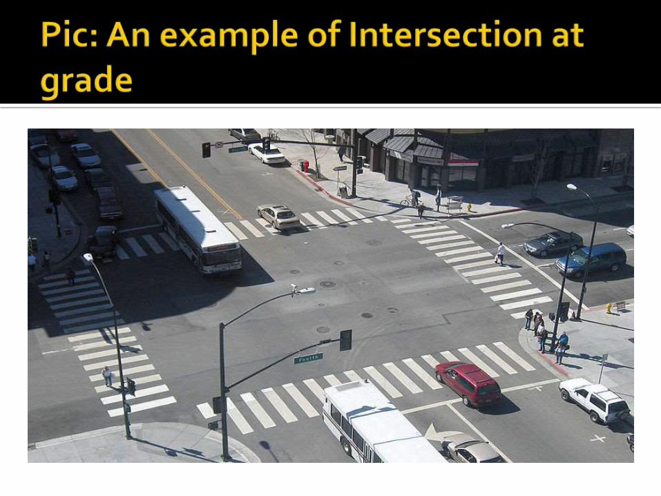
1. At-grade intersection2. Grade separated intersection An intersection where all roadways join or
cross at the same level. The traffic manoeuvres like merging, diverging and crossing are involved in the intersection at grade. It is further classified as
i. Un-channelizedii. Channelizediii. Rotary intersectioniv. Signalized intersection
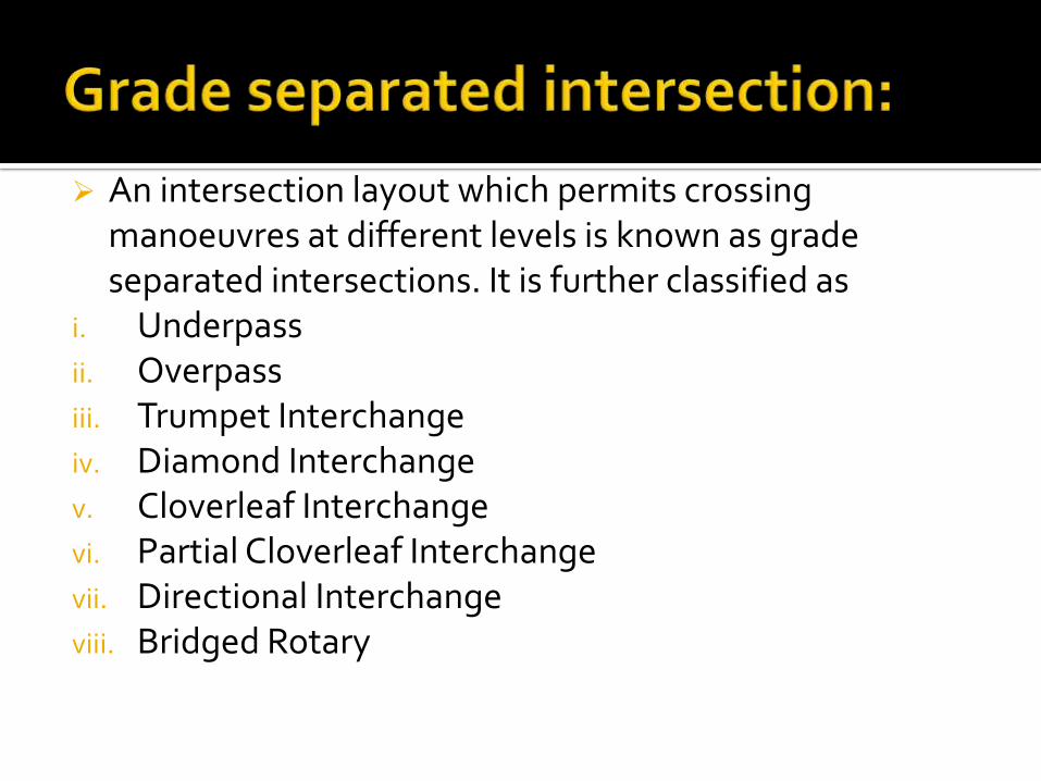
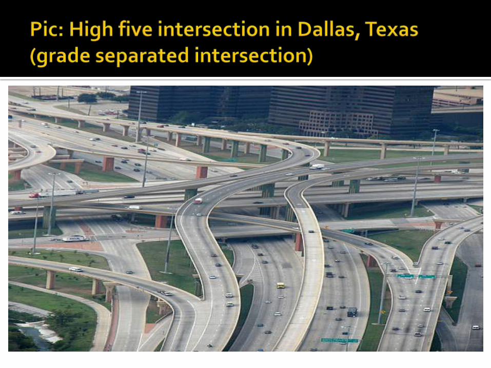
An intersection layout which permits crossing manoeuvres at different levels is known as grade separated intersections. It is further classified as
i. Underpassii. Overpassiii. Trumpet Interchangeiv. Diamond Interchangev. Cloverleaf Interchangevi. Partial Cloverleaf Interchangevii. Directional Interchangeviii. Bridged Rotary
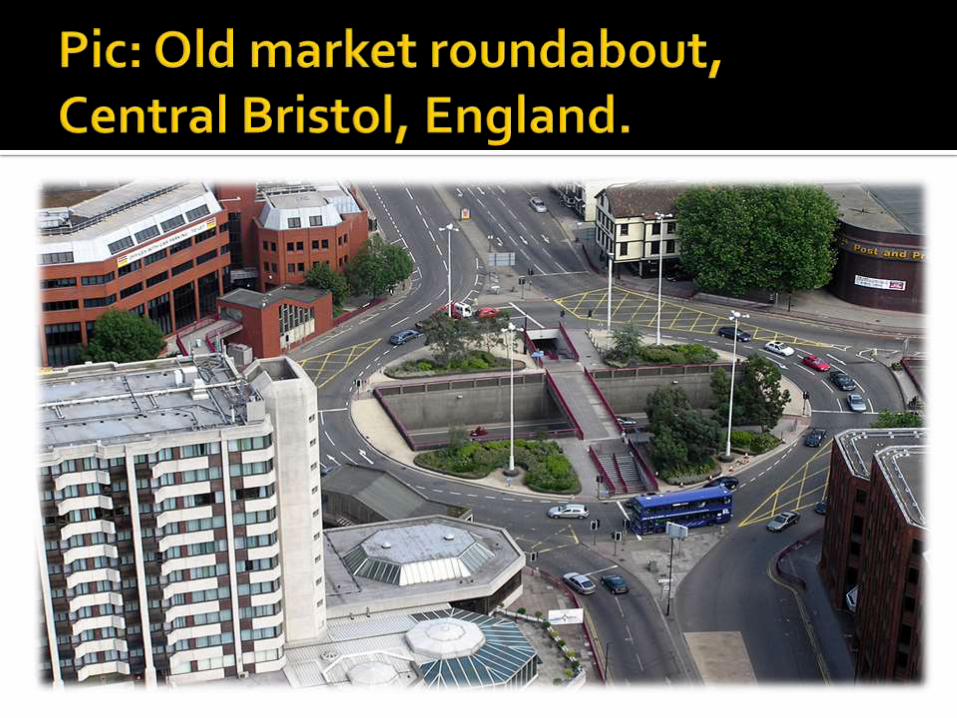
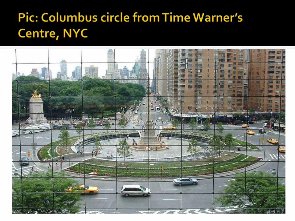
Rotary intersections or roundabouts are special form of at-grade intersections laid out for the movement of traffic in one direction around a central traffic island before they can weave out of traffic flow into their respective direction.
In India and other countries where ‘‘keep to the left’’ regulation is followed, the vehicles entering the rotary are gently forced to move in a clock-wise direction in orderly fashion.
1) Diverging: Traffic operation when the vehicles moving in one direction is separated into different streams.
2) Merging: Process of joining the traffic coming from different approaches and going to a common destination into a single stream.
3) Weaving: Combined movement of both merging and diverging movements in the same direction.

Design speed Entry , exit & island
rotary Width of the rotary Weaving length
Figure: Design elements of a rotary
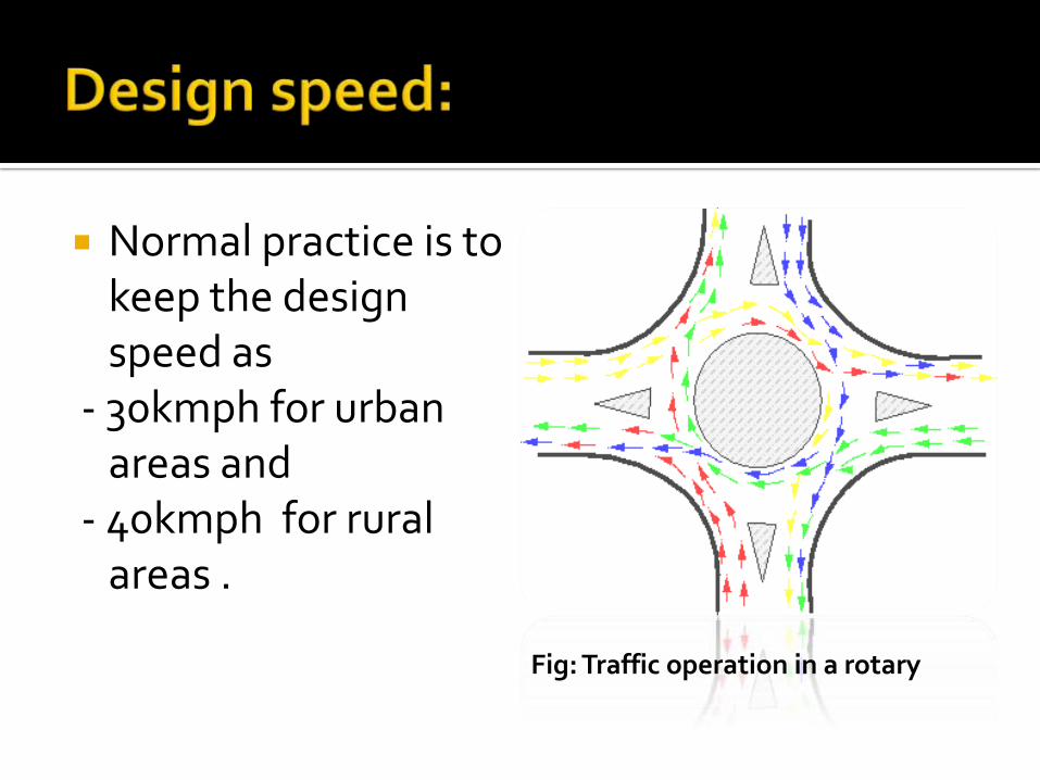
Normal practice is to keep the design speed as
- 30kmph for urban areas and
- 40kmph for rural areas .
Fig: Traffic operation in a rotary
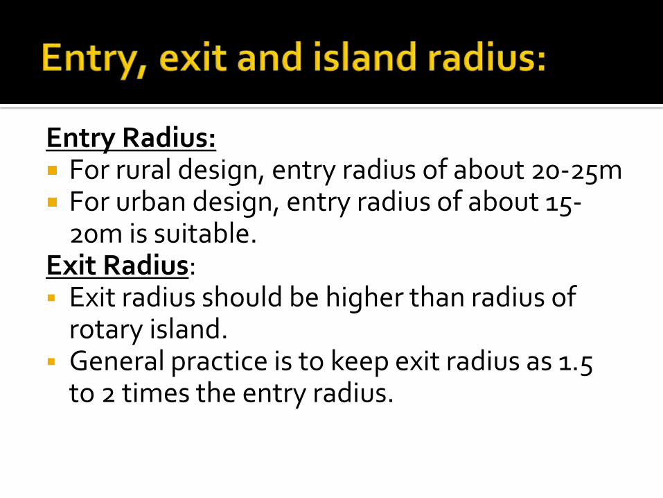
Entry Radius: For rural design, entry radius of about 20-25m For urban design, entry radius of about 15-
20m is suitable.Exit Radius: Exit radius should be higher than radius of
rotary island. General practice is to keep exit radius as 1.5
to 2 times the entry radius.
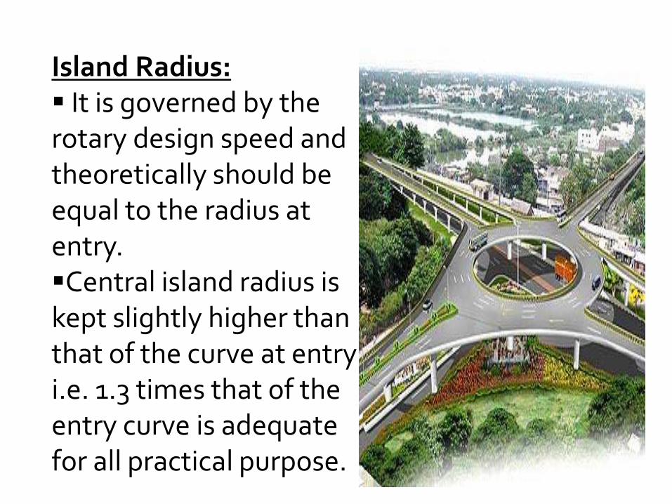
Island Radius: It is governed by the rotary design speed and theoretically should be equal to the radius at entry.Central island radius is kept slightly higher than that of the curve at entry i.e. 1.3 times that of the entry curve is adequate for all practical purpose.
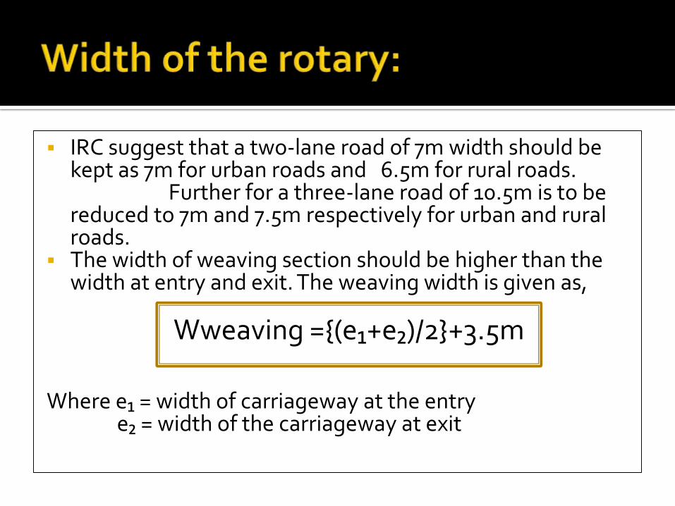
IRC suggest that a two-lane road of 7m width should be kept as 7m for urban roads and 6.5m for rural roads.
Further for a three-lane road of 10.5m is to be reduced to 7m and 7.5m respectively for urban and rural roads.
The width of weaving section should be higher than the width at entry and exit. The weaving width is given as,
Wweaving ={(e₁+e₂)/2}+3.5m
Where e₁ = width of carriageway at the entrye₂ = width of the carriageway at exit
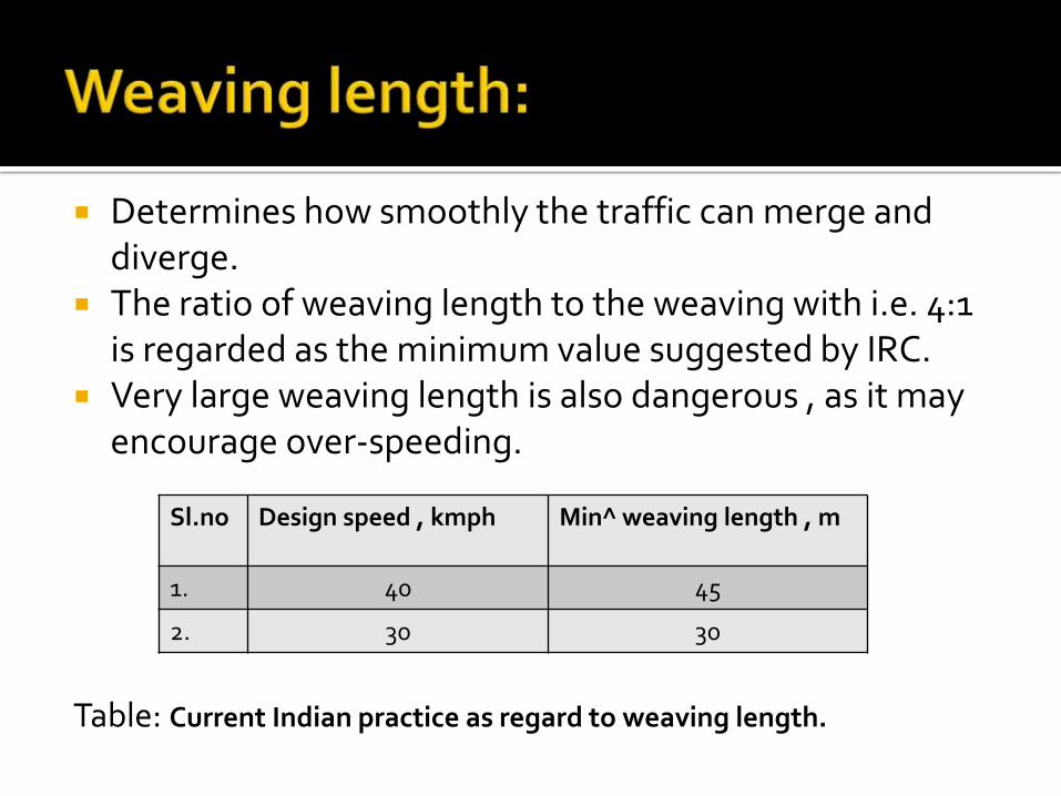
Determines how smoothly the traffic can merge and diverge.
The ratio of weaving length to the weaving with i.e. 4:1 is regarded as the minimum value suggested by IRC.
Very large weaving length is also dangerous , as it may encourage over-speeding.
Table: Current Indian practice as regard to weaving length.
Sl.no Design speed , kmph Min^ weaving length , m
1. 40 45
2. 30 30
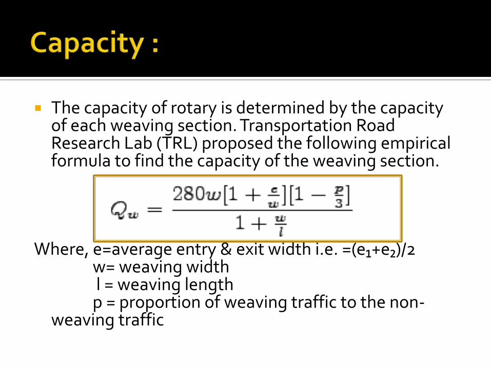
The capacity of rotary is determined by the capacity of each weaving section. Transportation Road Research Lab (TRL) proposed the following empirical formula to find the capacity of the weaving section.
Where, e=average entry & exit width i.e. =(e₁+e₂)/2w= weaving widthl = weaving lengthp = proportion of weaving traffic to the non-
weaving traffic
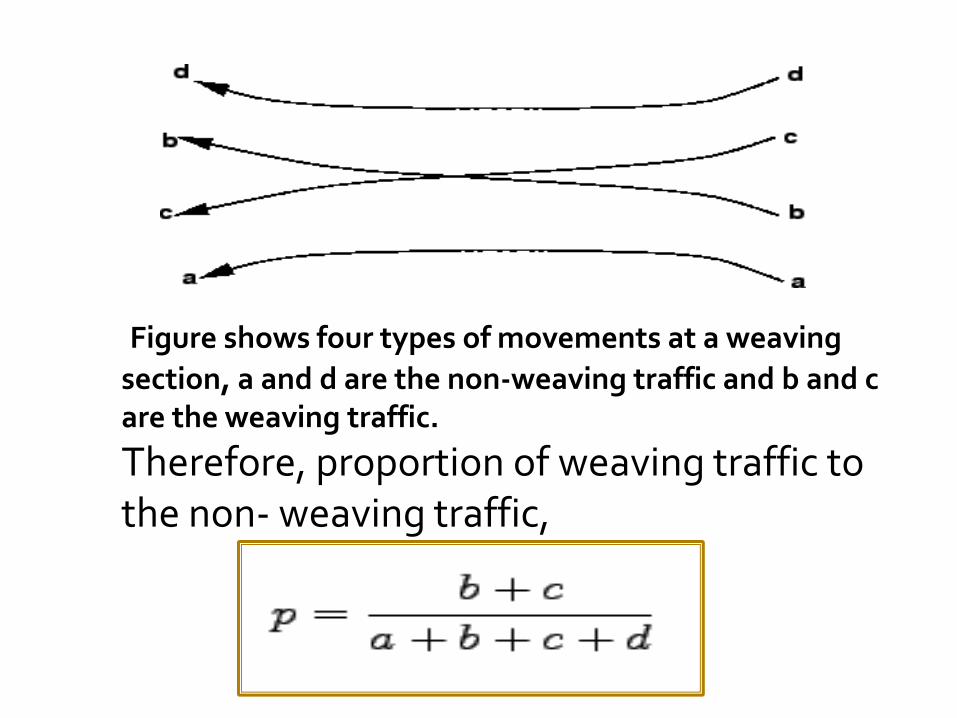
Figure shows four types of movements at a weaving
section, a and d are the non-weaving traffic and b and c are the weaving traffic.
Therefore, proportion of weaving traffic to the non- weaving traffic,
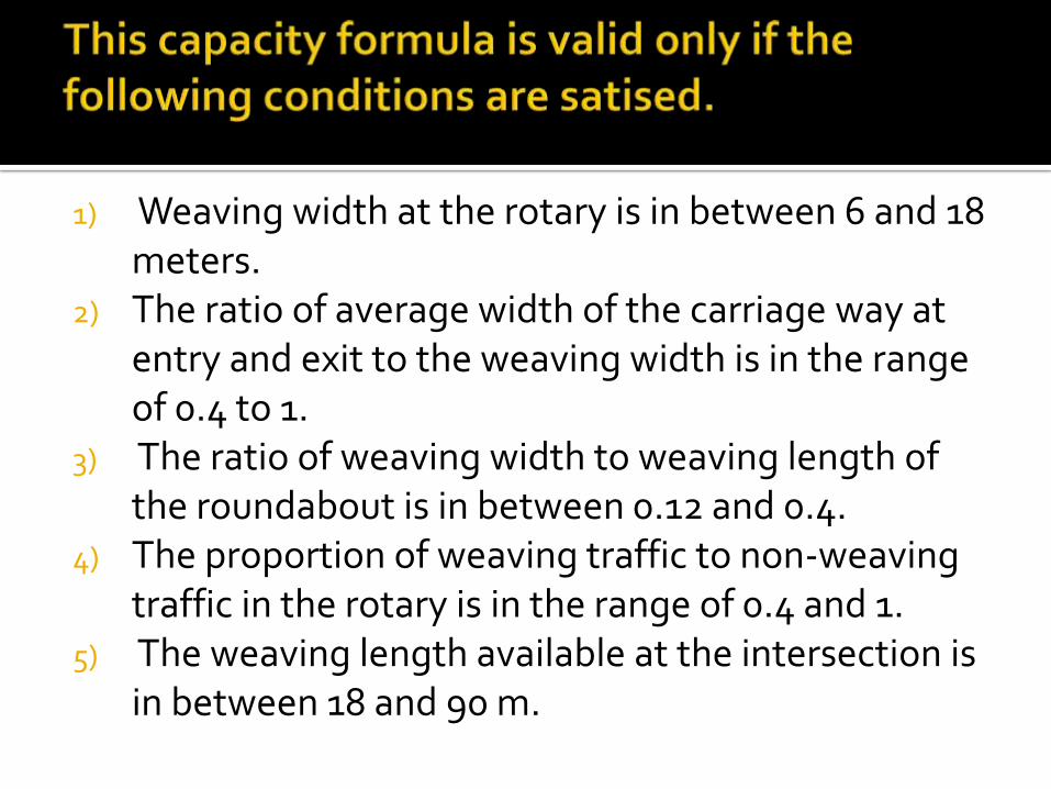
1) Weaving width at the rotary is in between 6 and 18 meters.
2) The ratio of average width of the carriage way at entry and exit to the weaving width is in the range of 0.4 to 1.
3) The ratio of weaving width to weaving length of the roundabout is in between 0.12 and 0.4.
4) The proportion of weaving traffic to non-weaving traffic in the rotary is in the range of 0.4 and 1.
5) The weaving length available at the intersection is in between 18 and 90 m.
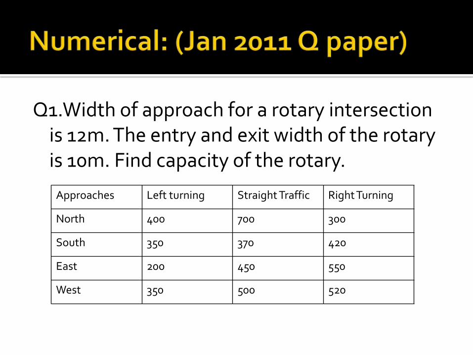
Q1.Width of approach for a rotary intersection is 12m. The entry and exit width of the rotary is 10m. Find capacity of the rotary.
Approaches Left turning Straight Traffic Right Turning
North 400 700 300
South 350 370 420
East 200 450 550
West 350 500 520
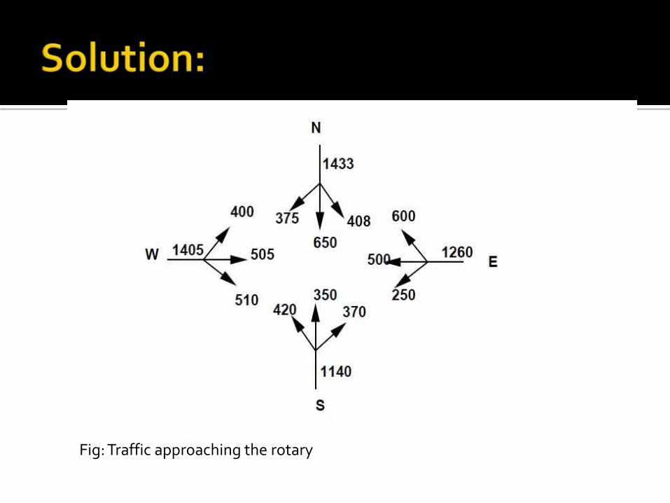
Fig: Traffic approaching the rotary
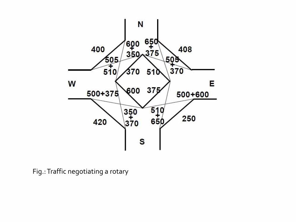
Fig.: Traffic negotiating a rotary

Weaving width is calculated as,w = [(e₁+e₂)/2] + 3:5 = 13.5 m
Weaving length is calculated asl = 4*w = 54 m
The proportion of weaving traffic to the non-weaving traffic in all the four approaches is found out first.
Let the proportion of weaving traffic to the non-weaving traffic in West-North direction be denoted as pWN, in North-East direction as pNE, in the East-South direction as pES, and finally in the South-West direction as pSW.

Then using equation,pES = (510+650+500+600)/(510+650+500+600+250+375)
= 2260/2885 = 0.783
pWN = (505+510+350+600/505+510+350+600+400+370)=1965/2735 = 0.718
pNE = (650+375+505+370/650+375+505+370+510+408)=1900/2818 = 0.674
pSW =( 350+370+500+375/350+370+500+375+420+600)=1595/2615 = 0.6099
Thus, the proportion of weaving traffic to non-weaving traffic is highest in the East-South direction.
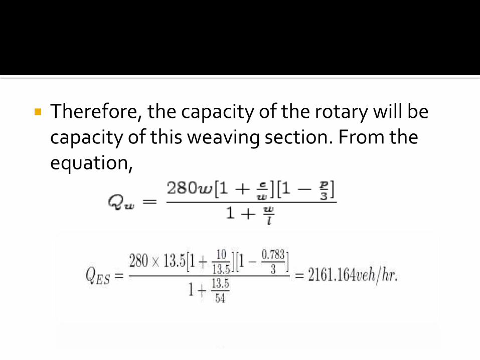
Therefore, the capacity of the rotary will be capacity of this weaving section. From the equation,
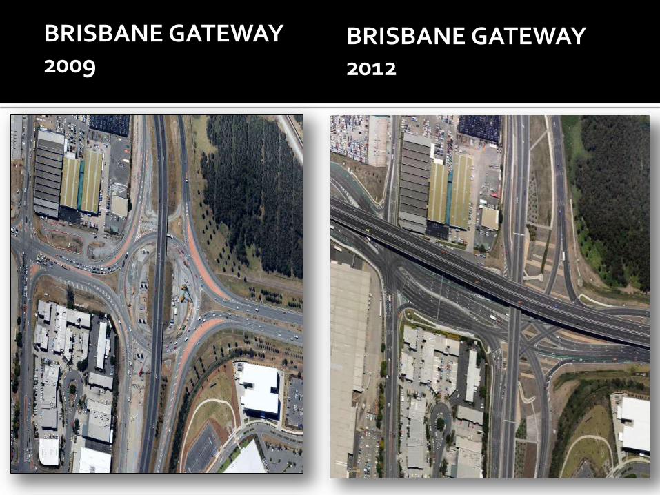
BRISBANE GATEWAY 2009
BRISBANE GATEWAY 2012
Traffic rotaries reduce the complexity of crossing traffic by forcing them into weaving operations.
The shape and size of the rotary are determined by the traffic volume and share of turning movements.
Capacity assessment of a rotary is done by analyzing the section having the greatest proportion of weaving traffic.
The analysis is done by using the formula given by TRL.
http://textofvideo.nptel.iitm.ac.in/105105107/lec6.pdf
http://www.skyscrapercity.com/showthread.php?t=1489703&page=2
http://www.civil.iitb.ac.in/tvm/1111_nptel/566_Rotary/plain/plain.html
L. R. Kadiyali, ‘Traffic Engineering and Transportation Planning’, Khanna Publishers, 8th
Edition:2013, New Delhi. S.K.Khanna, C.E.J.Justo, A.Veeraragavan,
‘Highway Engineering’ revised 10th edition 2014, Nem Chand & Bros, Roorkee