capeco final report 10.21.2015€¦ · u.s. chemical safety and hazard investigation board report...
TRANSCRIPT
U.S. Chemical Safety and Hazard Investigation Board
REPORT NO. 2010.02.I.PR
U.S. CHEMICAL SAFETY AND HAZARD INVESTIGATION BOARD
Final
Final
FINAL INVESTIGATION REPORT
CARIBBEAN PETROLEUM TANK TERMINAL
EXPLOSION AND MULTIPLE TANK FIRES
CARIBBEAN PETROLEUM CORPORATION (CAPECO)
KEY ISSUES: BAYAMÓN, PUERTO RICO
TANK OVERFILL PREVENTION OCTOBER 23, 2009
COMMUNITY IMPACT
HAZARD ASSESSMENT
SAFETY MANAGEMENT SYSTEM
REGULATION GAPS:
NO RISK ASSESSMENT CONSIDERING PROXIMITY TO COMMUNITIES
NO ADHERENCE TO RAGAGEP
NO REDUNDANT OR INDEPENDENT SAFEGUARDS TO PREVENT OVERFILLING A TANK
Caribbean Petroleum Company Final October 2015
2 U.S. CHEMICAL SAFETY AND HAZARD INVESTIGATION BOARD
Final
[Page intentionally left blank.]
Caribbean Petroleum Company Final October 2015
3 U.S. CHEMICAL SAFETY AND HAZARD INVESTIGATION BOARD
Final
CONTENTS CONTENTS .................................................................................................................................................................. 3
Acronyms and Abbreviations ................................................................................................................................... 7
PUERTO RICO EMERGENCY MANAGEMENT AGENCY .................................................................................... 8
1.0 EXECUTIVE SUMMARY ............................................................................................................................. 9
1.1 Incident Summary ........................................................................................................................................ 9
1.2 Public Impact and Emergency Response ..................................................................................................... 9
1.3 CSB Investigation ........................................................................................................................................ 9
1.4 CSB Findings ............................................................................................................................................. 10
1.5 Key Findings .............................................................................................................................................. 10
2.0 CARIBBEAN PETROLEUM CORPORATION .......................................................................................... 14
2.1 Company History ....................................................................................................................................... 14
2.2 Status of CAPECO ..................................................................................................................................... 14
2.3 Site Description .......................................................................................................................................... 14
3.0 SITE OPERATIONS ..................................................................................................................................... 16
3.1 Normal Site Operations .............................................................................................................................. 16
3.2 Tank Farm Operations ................................................................................................................................ 16
3.3 Storm Water and Oil Runoff Management ................................................................................................ 17
3.4 Ship Unloading and Tank-Filling Operations ............................................................................................ 17
3.5 Communication .......................................................................................................................................... 18
3.6 Process Description .................................................................................................................................... 18
4.0 INCIDENT DESCRIPTION ......................................................................................................................... 22
4.1 Physical Cause ........................................................................................................................................... 22
4.2 Tank Overflow ........................................................................................................................................... 25
4.3 Vapor Cloud Formation and Migration ...................................................................................................... 26
4.4 Open Dike Drain Valves ............................................................................................................................ 27
4.5 Ignition ....................................................................................................................................................... 28
5.0 EMERGENCY RESPONSE ......................................................................................................................... 29
5.1 Response Description ................................................................................................................................. 29
5.2 Response Assessment ................................................................................................................................. 30
5.3 Incident Impact .......................................................................................................................................... 31
5.4 Impact to the Commonwealth .................................................................................................................... 34
5.5 Environmental Impact ................................................................................................................................ 34
Caribbean Petroleum Company Final October 2015
4 U.S. CHEMICAL SAFETY AND HAZARD INVESTIGATION BOARD
Final
5.6 Impact to Transportation and Commerce ................................................................................................... 34
5.7 Impact of Overfill Incident on CAPECO ................................................................................................... 35
6.0 INCIDENT ANALYSIS ............................................................................................................................... 35
6.1 Systemic Failure at CAPECO Led to Failure of the Overfill Prevention System ...................................... 35
6.2 CAPECO History of Poorly Maintaining Terminal Operations ................................................................. 37
6.3 Previous Spill Incidents at CAPECO ......................................................................................................... 37
6.4 Normal Practice to Fill Tanks to Maximum Levels at Odds with Safety ................................................... 37
6.5 Unreliable Safety Critical Equipment ........................................................................................................ 38
6.6 Lack of Formal Procedures for Tank Terminal Operations ....................................................................... 42
6.7 Lack of Additional Safeguards such as High-Level Alarms and an Automatic Overfill Prevention System 42
6.8 Other Potential Contributing Factors ......................................................................................................... 43
6.9 Human Factors ........................................................................................................................................... 45
6.10 Using a Risk-based Approach to Design an Overfill Prevention System .................................................. 47
7.0 TANK LOCATIONS, PREVALENCE OF INCIDENTS AND LESSONS LEARNED FROM PREVIOUS CATASTROPHIC INCIDENTS ................................................................................................................... 49
7.1 Prevalence of Tank Incidents ..................................................................................................................... 50
7.2 Lessons Learned from Previous Incidents .................................................................................................. 51
7.3 Buncefield (Hertfordshire, UK) ................................................................................................................. 51
7.4 Texaco Oil Company (Newark, NJ) ........................................................................................................... 55
7.5 Indian Oil Company (Jaipur, India) ........................................................................................................... 55
8.0 REGULATORY ANALYSIS ....................................................................................................................... 56
8.1 Environmental Protection Agency (EPA) .................................................................................................. 58
8.2 Clean Air Act: The General Duty Clause ................................................................................................... 58
8.3 EPA: The List Rule .................................................................................................................................... 59
8.4 Risk Management Program ........................................................................................................................ 62
8.5 Chemical Accident Provisions, Risk Management Plan (RMP) ................................................................ 62
8.6 The Clean Water Act (CWA) ..................................................................................................................... 63
8.7 Occupational Safety and Health Administration (OSHA) ......................................................................... 70
8.8 Puerto Rico Occupational Safety and Health Administration (PR OSHA) ................................................ 73
8.9 Recognized and Generally Accepted Good Engineering Practices (RAGAGEP) ...................................... 73
8.10 Industry and Consensus Standards ......................................................................................................... 74
8.11 Trade Associations ................................................................................................................................. 83
9.0 ROOT AND SYSTEMIC CAUSES ............................................................................................................. 83
10.0 RECOMMENDATIONS .............................................................................................................................. 86
Caribbean Petroleum Company Final October 2015
5 U.S. CHEMICAL SAFETY AND HAZARD INVESTIGATION BOARD
Final
Figures
Figure 1. CAPECO tank farm, WWT, and decommissioned refinery overview……………………….....15
Figure 2. CAPECO Pipeline to Gulf Oil Dock where gasoline is offloaded from ship..……………….....16
Figure 3. (A) Manual and (B) Automatic tank gauging…………………………………………………...19
Figure 4. Side gauge mounted on side of a fuel storage tank displaying the liquid levels…………..……21
Figure 5. CAPECO multiple tank farm fire, October 23, 2009………………………………………… 24
Figure 6. Impact of the explosion and multiple tank fires after the October 23, 2009 incident…………..24
Figure 7. Topographic Survey of CAPECO Tank Farm………………………….………………………27
Figure 8. CAPECO surveillance footage of flame propagation during CAPECO
explosion…………………………………………………………………………..………………………27
Figure 9. Communities neighboring the CAPECO facility……………………………………………….32
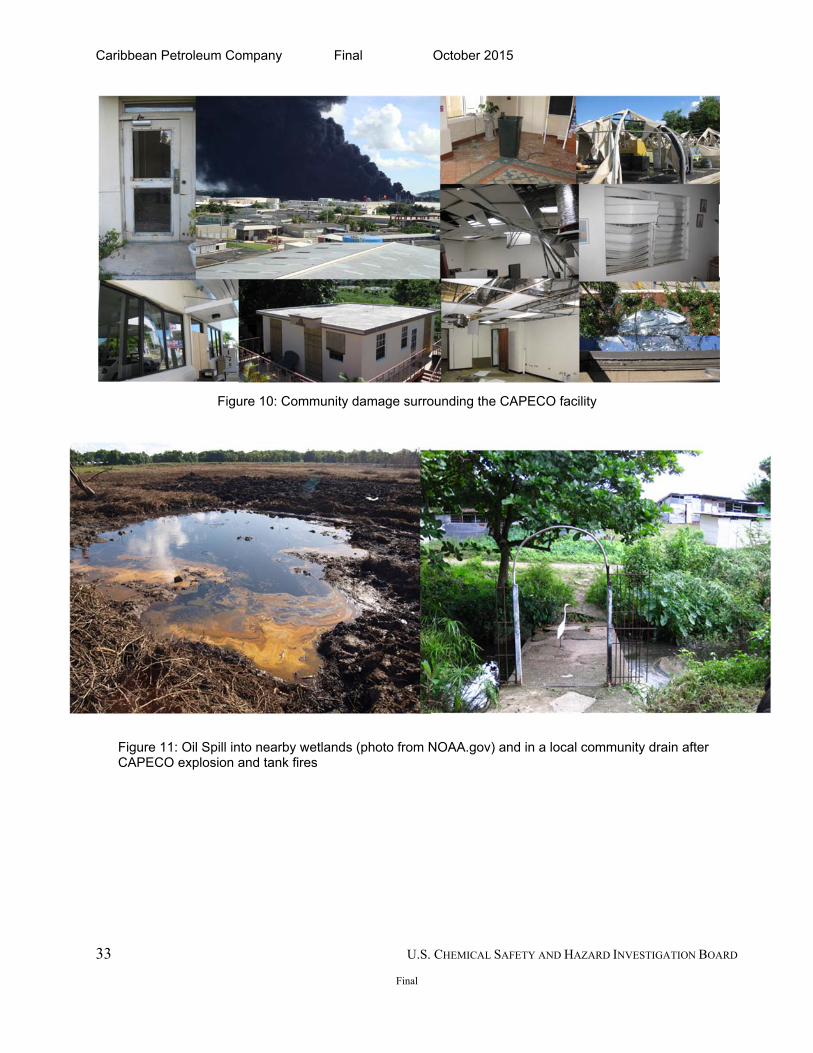
Figure 10. Community damage surrounding the CAPECO facility…………….……………………..… 33
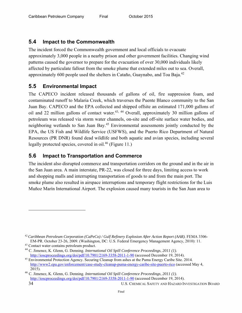
Figure 11. Oil Spill into nearby wetlands and in a local community drain after CAPECO explosion and
tank fires …………………………………………………………………………………………..………33
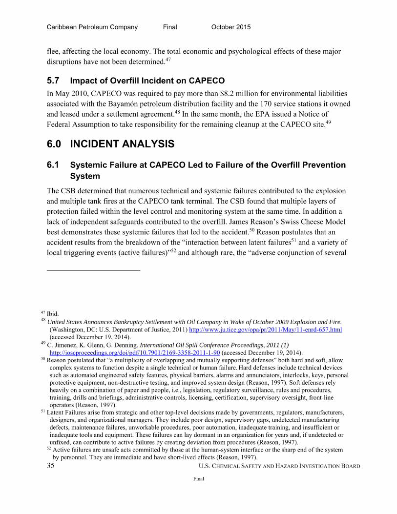
Figure 12. Failure of Multiple Layers of Protection and Lack of Independent Prevention Safeguards at
CAPECO……………………………………………………………………………………………….…36
Figure 13 Schematic of a Comprehensive Level Overfill Prevention System…………………………....39
Figure 14. Tank 409 Specifications………………………………………………………………….……45
Figure 15. Various dike drain valves at CAPECO. ….……………………………………………………47
Figure 16. Distribution of tank terminals across the US ………………………………………………… 51
Figure 17. Regulatory Policies Governing Above Ground Storage Tanks ………………………………58
Caribbean Petroleum Company Final October 2015
6 U.S. CHEMICAL SAFETY AND HAZARD INVESTIGATION BOARD
Final
Tables
Table 1. Estimated Volume of Gasoline Overfilling from Tank 409 …………………………………….25
Table 2. Comparison of CAPECO and Buncefield Incidents ..................................................................... 55
Appendix
Appendix A. Incident Timeline……………………………………………….…..………..……93
Appendix B. Previous Incidents……………………………………………..………….……….94
Appendix C. Caribbean Petroleum AcciMap……..……………..……………………...….…..103
Caribbean Petroleum Company Final October 2015
7 U.S. CHEMICAL SAFETY AND HAZARD INVESTIGATION BOARD
Final
Acronyms and Abbreviations
ALARP As low as reasonably practicable AOPS Automatic Overfill Prevention SystemAPI American Petroleum Institute AST Aboveground Storage Tank ATF Bureau of Alcohol, Tobacco, Firearms and Explosives ATG Automatic Tank Gauge Bbls Barrels bbls/hr Barrels per hour BSTG Buncefield Standards Task Group CA Competent Authority CAA Clean Air Act CAAA Clean Air Act Amendments CAPECO Caribbean Petroleum Company cbm/hr Cubic meter per hour CCPS Center for Chemical Process Safety CERCLA Comprehensive Environmental Response, Compensation, and Liability CH Critical high level COMAH Control of Major Accident Hazards CSB U.S. Chemical Safety and Hazard Investigation Board CWA Clean Water Act DFA Direct Federal Assistance DOH Department of Health DOJ Department of Justice EPA Environmental Protection Agency ESF Emergency Support Function Annexes FEMA Federal Emergency Response Agency FRP Federal Response Plans HAZOP Hazard and Operability Study HH High-high level HSE Health and Safety Executive ICC International Codes Council IFC International Fire Code IFR Internal Floating Roof ILTA International Liquid Terminals Association IOC Indian Oil Corporation (IOC) Petroleum Oil Lubricants IPL Independent Protection Layer
Caribbean Petroleum Company Final October 2015
8 U.S. CHEMICAL SAFETY AND HAZARD INVESTIGATION BOARD
Final
IPAA Independent Petroleum Association of America ISA International Society for Automation JIC Joint Incident Command kPa Kilopascal LOC Level of concern MIIB Major Incident Investigation Board MOC Management of Change Mph Miles per hour MW Maximum Working Level NASA National Aeronautics and Space Administration NIMS Incident Command System/National Incident Management NFPA National Fire Protection Association OPA Oil Pollution Act OPP Overfill Prevention Process OSHA Occupational Safety and Health Administration PREPA Puerto Rico Electric Power Authority PHA Process Hazard Analysis PR DNR Puerto Rico Department of Natural Resources PR OSHA Puerto Rico Occupation Safety Health and Administration PREMA Puerto Rico Emergency Management Agency Psi Pounds per square inch Psia Pounds per square inch absolute PSM Process Safety Management RAGAGEP Recognized and Generally Accepted Good Engineering Practices RCRA Resource Conservation and Recovery Act RMP Risk Management Program SBA Small Business Administration SCO State Coordinating Officer SIF Safety Instrumented Functions SIL Safety Integrity Levels SIS Safety Instrumented System SOPs Standard Operating Procedures UCP Unified Command Post UK United Kingdom USCG US Coast Guard USFWS US Fish and Wildlife Service WWT Wastewater treatment
Caribbean Petroleum Company Final October 2015
9 U.S. CHEMICAL SAFETY AND HAZARD INVESTIGATION BOARD
Final
1.0 EXECUTIVE SUMMARY
1.1 Incident Summary
On the night of October 23, 2009, a large explosion occurred at the Caribbean Petroleum Corporation (CAPECO) facility in Bayamón, Puerto Rico, during offloading of gasoline from a tanker ship, the Cape Bruny, to the CAPECO tank farm onshore. A 5-million gallon aboveground storage tank (AST) overflowed into a secondary containment dike. The gasoline spray aerosolized, forming a large vapor cloud, which ignited after reaching an ignition source in the wastewater treatment (WWT) area of the facility. The blast and fire from multiple secondary explosions resulted in significant damage to 17 of the 48 petroleum storage tanks and other equipment onsite and in neighborhoods and businesses offsite. The fires burned for almost 60 hours. Petroleum products leaked into the soil, nearby wetlands and navigable waterways in the surrounding area.
1.2 Public Impact and Emergency Response
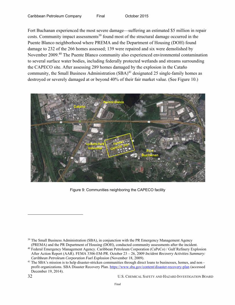
The blast created a pressure wave registering 2.9 on the Richter scale1 and damaging approximately 300 homes and businesses up to 1.25 miles from the site. In particular, the nearby Fort Buchanan military facility suffered over $5 million in damages; air and vehicle transportation was interrupted; and thousands of gallons of oil, fire suppression foam, and contaminated runoff were released to the environment. (Figures 9 and 10 show a map of communities neighboring the CAPECO facility and community damage.) CAPECO and the local fire department lacked the appropriate equipment or training to extinguish multiple tank fires, prolonging the environmental effects of the incident. The accident resulted in an emergency declaration for assistance from President Obama for the affected municipalities.
1.3 CSB Investigation
The CSB team arrived at the incident scene two days after the October 23, 2009, incident. The investigation team photo-documented the incident site, inventoried key evidence, interviewed witnesses, and assessed community damages. The team consulted tank experts and researched previous tank overfill incident investigations. Using several analytical tools, including timeline construction (Appendix A) and logic tree and AcciMap analysis2 (Appendix C), the team
1 Puerto Rico Seismic Network. Informe Especial, Explosión de Caribbean Petroleum en Bayamón, PR, 23 de octubre de 2009. University of Puerto Rico Mayagüez Campus.
2 AcciMap analysis is a causal diagram showing how factors remote from the immediate accident sequence contribute to the accident. Hopkins, A. An AcciMap of the Esso Australia Gas Plant Explosion. Australian
Caribbean Petroleum Company Final October 2015
10 U.S. CHEMICAL SAFETY AND HAZARD INVESTIGATION BOARD
Final
determined the root and systemic causes of this incident. The CSB investigators coordinated their work with the Puerto Rico Occupational Safety and Health Administration (PR OSHA) and the US Environmental Protection Agency (EPA).
1.4 CSB Findings
The CSB finds US regulations fail to consider bulk petroleum storage tank terminals similar to CAPECO as high-hazard facilities. Insufficient regulatory requirements for a hazard assessment, an unreliable level control and monitoring system, inadequate independent or redundant level alarms, and a poor safety management system led to CAPECO operating a high-hazard facility without the safeguards3 necessary to prevent overfill. In addition, the CSB found the local Puerto Rico fire department was unprepared to address a vapor cloud explosion and multiple tank fires. This incident demonstrates that bulk aboveground tank terminals near residential populations are high-hazard facilities, and therefore regulations requiring a risk assessment and multiple layers of protection to prevent overfilling a tank, are necessary to protect workers and the public.
1.5 Key Findings
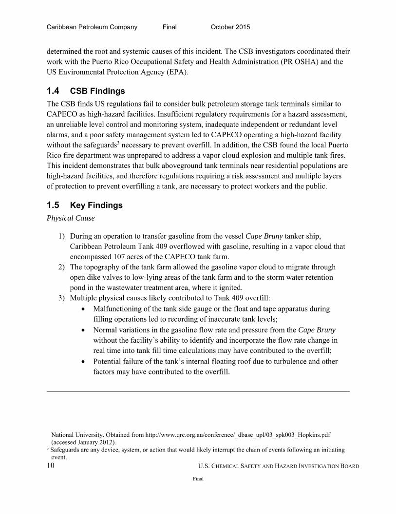
Physical Cause
1) During an operation to transfer gasoline from the vessel Cape Bruny tanker ship, Caribbean Petroleum Tank 409 overflowed with gasoline, resulting in a vapor cloud that encompassed 107 acres of the CAPECO tank farm.
2) The topography of the tank farm allowed the gasoline vapor cloud to migrate through open dike valves to low-lying areas of the tank farm and to the storm water retention pond in the wastewater treatment area, where it ignited.
3) Multiple physical causes likely contributed to Tank 409 overfill:
Malfunctioning of the tank side gauge or the float and tape apparatus during filling operations led to recording of inaccurate tank levels;
Normal variations in the gasoline flow rate and pressure from the Cape Bruny without the facility’s ability to identify and incorporate the flow rate change in real time into tank fill time calculations may have contributed to the overfill;
Potential failure of the tank’s internal floating roof due to turbulence and other factors may have contributed to the overfill.
National University. Obtained from http://www.qrc.org.au/conference/_dbase_upl/03_spk003_Hopkins.pdf (accessed January 2012).
3 Safeguards are any device, system, or action that would likely interrupt the chain of events following an initiating event.
Caribbean Petroleum Company Final October 2015
11 U.S. CHEMICAL SAFETY AND HAZARD INVESTIGATION BOARD
Final
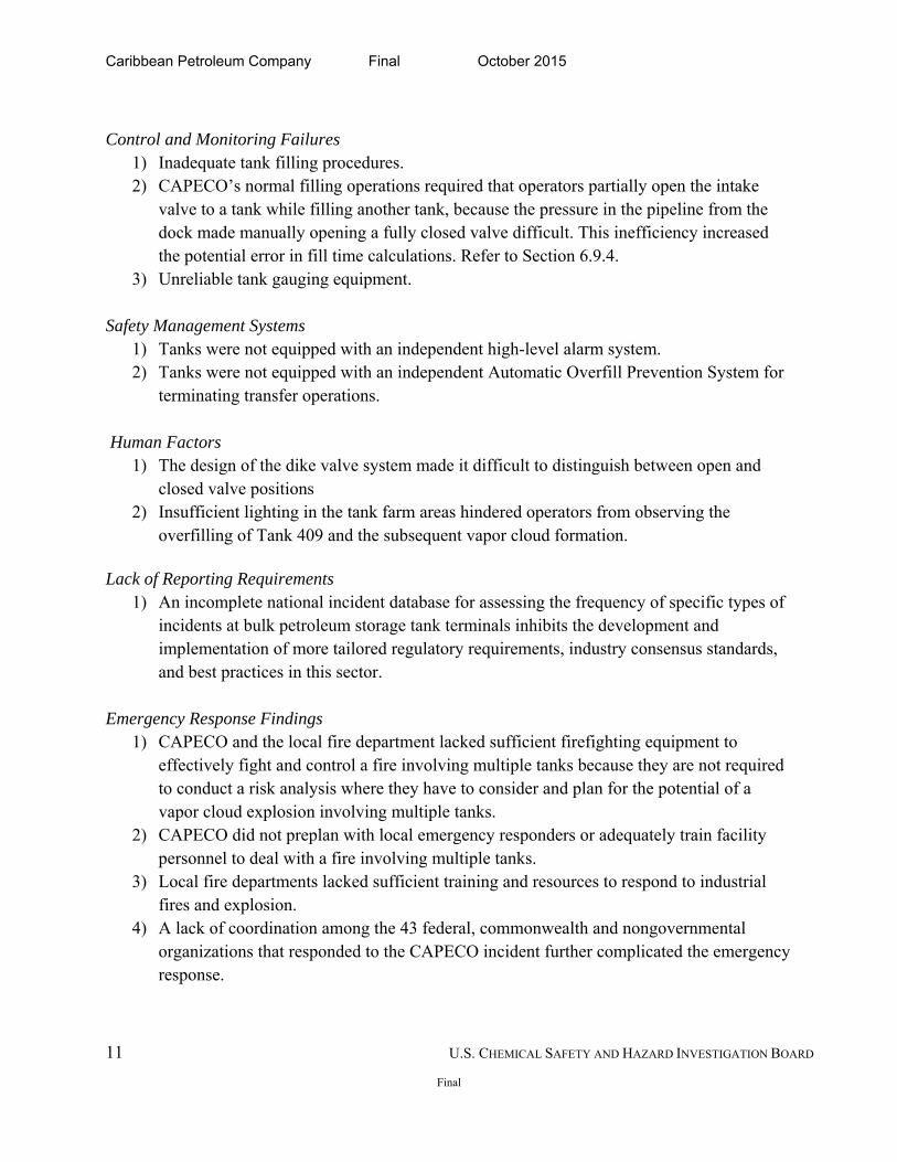
Control and Monitoring Failures
1) Inadequate tank filling procedures. 2) CAPECO’s normal filling operations required that operators partially open the intake
valve to a tank while filling another tank, because the pressure in the pipeline from the dock made manually opening a fully closed valve difficult. This inefficiency increased the potential error in fill time calculations. Refer to Section 6.9.4.
3) Unreliable tank gauging equipment.
Safety Management Systems 1) Tanks were not equipped with an independent high-level alarm system. 2) Tanks were not equipped with an independent Automatic Overfill Prevention System for
terminating transfer operations.
Human Factors 1) The design of the dike valve system made it difficult to distinguish between open and
closed valve positions 2) Insufficient lighting in the tank farm areas hindered operators from observing the
overfilling of Tank 409 and the subsequent vapor cloud formation. Lack of Reporting Requirements
1) An incomplete national incident database for assessing the frequency of specific types of incidents at bulk petroleum storage tank terminals inhibits the development and implementation of more tailored regulatory requirements, industry consensus standards, and best practices in this sector.
Emergency Response Findings 1) CAPECO and the local fire department lacked sufficient firefighting equipment to
effectively fight and control a fire involving multiple tanks because they are not required to conduct a risk analysis where they have to consider and plan for the potential of a vapor cloud explosion involving multiple tanks.
2) CAPECO did not preplan with local emergency responders or adequately train facility personnel to deal with a fire involving multiple tanks.
3) Local fire departments lacked sufficient training and resources to respond to industrial fires and explosion.
4) A lack of coordination among the 43 federal, commonwealth and nongovernmental organizations that responded to the CAPECO incident further complicated the emergency response.
Caribbean Petroleum Company Final October 2015
12 U.S. CHEMICAL SAFETY AND HAZARD INVESTIGATION BOARD
Final
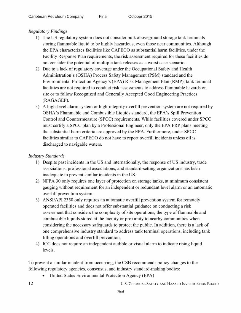
Regulatory Findings 1) The US regulatory system does not consider bulk aboveground storage tank terminals
storing flammable liquid to be highly hazardous, even those near communities. Although the EPA characterizes facilities like CAPECO as substantial harm facilities, under the Facility Response Plan requirements, the risk assessment required for these facilities do not consider the potential of multiple tank releases as a worst case scenario.
2) Due to a lack of regulatory coverage under the Occupational Safety and Health Administration’s (OSHA) Process Safety Management (PSM) standard and the Environmental Protection Agency’s (EPA) Risk Management Plan (RMP), tank terminal facilities are not required to conduct risk assessments to address flammable hazards on site or to follow Recognized and Generally Accepted Good Engineering Practices (RAGAGEP).
3) A high-level alarm system or high-integrity overfill prevention system are not required by OSHA’s Flammable and Combustible Liquids standard, the EPA’s Spill Prevention Control and Countermeasure (SPCC) requirements. While facilities covered under SPCC must certify a SPCC plan by a Professional Engineer, only the EPA FRP plans meeting the substantial harm criteria are approved by the EPA. Furthermore, under SPCC facilities similar to CAPECO do not have to report overfill incidents unless oil is discharged to navigable waters.
Industry Standards 1) Despite past incidents in the US and internationally, the response of US industry, trade
associations, professional associations, and standard-setting organizations has been inadequate to prevent similar incidents in the US.
2) NFPA 30 only requires one layer of protection on storage tanks, at minimum consistent gauging without requirement for an independent or redundant level alarm or an automatic overfill prevention system.
3) ANSI/API 2350 only requires an automatic overfill prevention system for remotely operated facilities and does not offer substantial guidance on conducting a risk assessment that considers the complexity of site operations, the type of flammable and combustible liquids stored at the facility or proximity to nearby communities when considering the necessary safeguards to protect the public. In addition, there is a lack of one comprehensive industry standard to address tank terminal operations, including tank filling operations and overfill prevention.
4) ICC does not require an independent audible or visual alarm to indicate rising liquid levels.
To prevent a similar incident from occurring, the CSB recommends policy changes to the following regulatory agencies, consensus, and industry standard-making bodies:
United States Environmental Protection Agency (EPA)
Caribbean Petroleum Company Final October 2015
13 U.S. CHEMICAL SAFETY AND HAZARD INVESTIGATION BOARD
Final
United States Occupational Safety and Health Administration (OSHA)
American Petroleum Institute (API)
International Code Council (ICC)
National Fire Protection Association (NFPA)
Caribbean Petroleum Company Final October 2015
14 U.S. CHEMICAL SAFETY AND HAZARD INVESTIGATION BOARD
Final
2.0 CARIBBEAN PETROLEUM CORPORATION
2.1 Company History
Petroleum refining operations first began at the CAPECO site in Bayamón, Puerto Rico in 1955. Ownership changed several times in the decades following the purchase of the refinery by Gulf Oil Corporation in 1962 and Chevron Corporation in 1984. First Oil Corporation acquired the refinery in 1987 and operated it as a 48,000 barrel-per-day petroleum refining facility until 2000,4 when the refinery closed. After filing for bankruptcy in 2001, the company reorganized and reduced operations to the terminal and 170 Gulf service stations throughout Puerto Rico. CAPECO filed for bankruptcy in 2001 and reorganized in 2003 to operate solely as a petroleum storage terminal and distribution facility.
2.2 Status of CAPECO
In August 2010, CAPECO declared bankruptcy. (See Section 5.7.) On May 11, 2010, Puma Energy Caribe, LLC acquired the Bayamón facility and other CAPECO assets under a broader EPA settlement. The settlement required cleanup activities under the Comprehensive Environmental Response, Compensation, and Liability Act (CERCLA),5 Resource Conservation and Recovery Act (RCRA),6 and Oil Pollution Act (OPA).7
2.3 Site Description
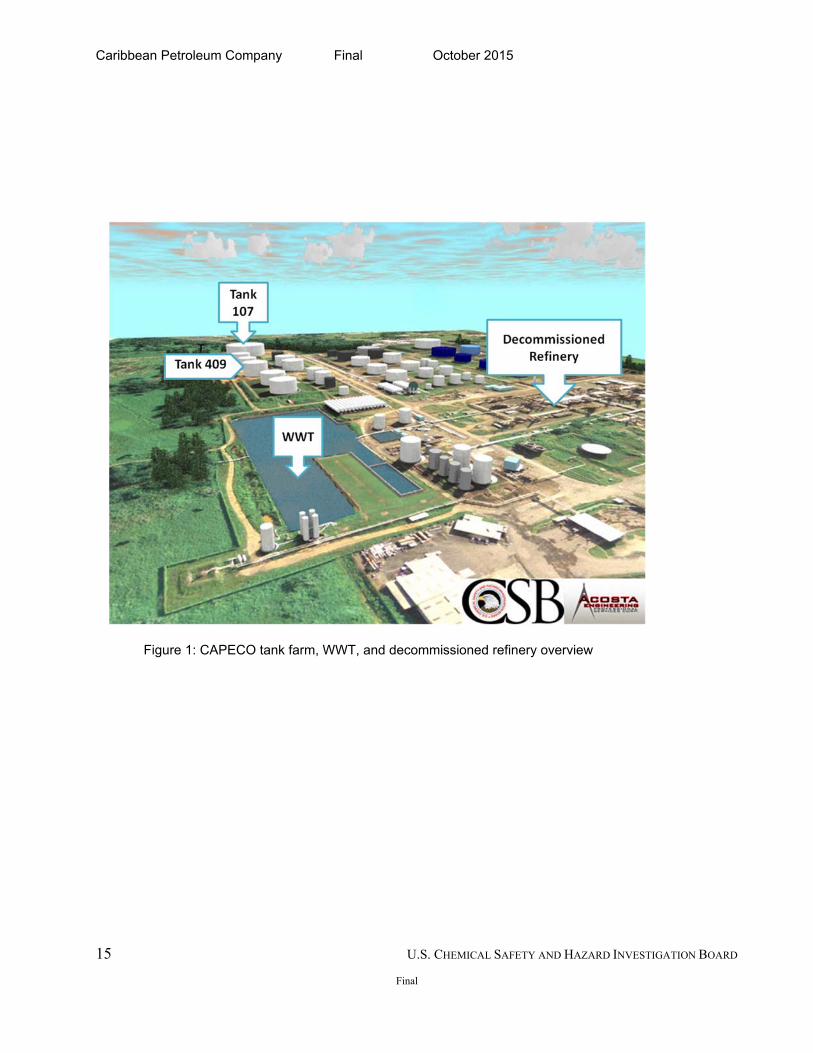
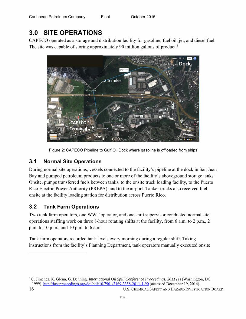
The CAPECO site covered 179 acres, 115 of which were developed into four areas: a tank farm, the decommissioned refinery, an administration area, and a wastewater treatment (WWT) plant. (See Figure 1.) The facility also owned and operated a loading dock on San Juan Bay in Guaynabo, 2.5 miles northeast of the site. (See Figure 2.) At the time of the incident, CAPECO employed 65 people.
4 Documentation of Environmental Indicator Determination RCRA Corrective Action Environmental Indicator (EI) RCRIS Code (CA725), Current Human Exposures Under Control (U.S. Environmental Protection Agency, 1999).
5 Congress enacted CERCLA, commonly known as Superfund, in 1980 to provide tax collected money to federal authorities to respond directly to releases or threatened releases of hazardous substances that may endanger public health or the environment. CERCLA Overview (Washington, DC: U.S. Environmental Protection Agency). http://www.epa.gov/superfund/policy/cercla.htm (accessed December 19, 2014).
6 RCRA, enacted in 1976, gives EPA the authority to control hazardous waste from “cradle to grave.” U.S. Environmental Protection Agency. http://www2.epa.gov/aboutepa/new-law-control-hazardous-wastes-end-open-dumping-promote-conservation-resources (accessed December 19, 2014).
7 Signed into law in August 1990, the OPA improved the nation’s ability to prevent and respond to oil spills by establishing provisions that expand the Federal government’s ability and provide money and resources necessary to respond to oil spills. Oil Pollution Act Overview (Washington, DC: U.S. Environmental Protection Agency). http://www.epa.gov/osweroe1/content/lawsregs/opaover.htm (accessed December 19, 2014).
Caribbean Petroleum Company Final October 2015
15 U.S. CHEMICAL SAFETY AND HAZARD INVESTIGATION BOARD
Final
Figure 1: CAPECO tank farm, WWT, and decommissioned refinery overview
Caribbean Petroleum Company Final October 2015
16 U.S. CHEMICAL SAFETY AND HAZARD INVESTIGATION BOARD
Final
3.0 SITE OPERATIONS CAPECO operated as a storage and distribution facility for gasoline, fuel oil, jet, and diesel fuel. The site was capable of storing approximately 90 million gallons of product.8
Figure 2: CAPECO Pipeline to Gulf Oil Dock where gasoline is offloaded from ships
3.1 Normal Site Operations
During normal site operations, vessels connected to the facility’s pipeline at the dock in San Juan Bay and pumped petroleum products to one or more of the facility’s aboveground storage tanks. Onsite, pumps transferred fuels between tanks, to the onsite truck loading facility, to the Puerto Rico Electric Power Authority (PREPA), and to the airport. Tanker trucks also received fuel onsite at the facility loading station for distribution across Puerto Rico.
3.2 Tank Farm Operations
Two tank farm operators, one WWT operator, and one shift supervisor conducted normal site operations staffing work on three 8-hour rotating shifts at the facility, from 6 a.m. to 2 p.m., 2 p.m. to 10 p.m., and 10 p.m. to 6 a.m.
Tank farm operators recorded tank levels every morning during a regular shift. Taking instructions from the facility’s Planning Department, tank operators manually executed onsite
8 C. Jimenez, K. Glenn, G. Denning. International Oil Spill Conference Proceedings, 2011 (1) (Washington, DC, 1999). http://ioscproceedings.org/doi/pdf/10.7901/2169-3358-2011-1-90 (accessed December 19, 2014).
2.5 miles
CAPECO Terminal
Dock
Caribbean Petroleum Company Final October 2015
17 U.S. CHEMICAL SAFETY AND HAZARD INVESTIGATION BOARD
Final
fuel transfers, blending gasoline with methanol, pumping products to PREPA and the airport via the pipeline, and receiving shipments from the dock in San Juan Bay.
3.3 Storm Water and Oil Runoff Management
Normal operations at the tank farm required that one operator inspect the secondary containment area for accumulating storm water and oil. Operations staff managed the secondary containment valves that drained storm water through storm water pipes to the storm water retention pond in the WWT plant. The morning operator closed the dike valves after rainstorms, and the evening WWT operator (2 p.m. to 10 p.m.) verified the valves were closed. Operators then recorded the secondary containment valve position in a valve inspection log. When oil was present in secondary containment, operators used a vacuum truck to remove it. (See Section 6.9.1.)
3.4 Ship Unloading and Tank-Filling Operations
The CAPECO Planning and Economics Department (Planning Department) was integral to the operations of the tank farm and management of fuel transfer operations.9 Its staff coordinated fuel deliveries with the company and its fuel suppliers and instructed operators on which tank to fill, specified the volume of materials, and determined the filling schedule during unloading operations. Similar to other tank terminals, the CAPECO Planning Department directed operations in the tank farm. After obtaining tank levels from the night-shift operations staff, the Planning Department rented tank space to various petroleum vendors interested in storing gasoline, jet fuel, or fuel oil. Prior to product delivery, the Planning Department, the petroleum vendor, and the fuel distributor, in this case the Cape Bruny, negotiated a fee schedule for charging CAPECO based on the length of time to complete tank-filling operations at the terminal. The purchase terms, fee schedules and delivery contracts contained credits and penalties for all parties involved in offloading operations. If CAPECO operators completed filling operations in less than the allotted time, the Cape Bruny would refund CAPECO fees for the unused time. If filling operations took longer, the Cape Bruny could charge CAPECO the negotiated rate for the additional time. The Daily Operation Report from the Planning Department contained all filling instructions,
9 Transfer operations for receiving a product into a tank encompasses all associated activities, including notification (verbally, electronically, or by other means) of a potential tank overfill and termination of flow into the tank (shutdown or diversion of product). American Petroleum Institute. ANSI/API Standard 2350. Fourth edition (Washington, DC: American Petroleum Institute, May 1, 2012).
Caribbean Petroleum Company Final October 2015
18 U.S. CHEMICAL SAFETY AND HAZARD INVESTIGATION BOARD
Final
including the level of product the tank should receive and the time it should take to fill the tank to the appropriate level. The Planning Department calculated the time based on the capacity of the pipeline and the volume discharged from the ship. CAPECO operations personnel were required to report any discrepancies in filling time to the Planning Department.
3.5 Communication
Due to the manual nature of operations, communication was essential to the success of the unloading process. During unloading operations, the operators remained in communication via radio with the WWT operator or the shift supervisor to ensure all necessary valve alignments and efficient switching between tanks occurred. Tank sizes varied at the CAPECO tank terminal, and only one tank, Tank 107 (Figure 1), was large enough to receive a full shipload of gasoline from the Cape Bruny tanker ship. In addition, due to storage limitations only a few designated tanks held gasoline. Because of this arrangement, CAPECO tank operators commonly switched flow among multiple tanks during unloading operations of a single shipment, requiring constant contact between tank operators and the shift supervisor.
3.6 Process Description
3.6.1 Level Measurements
CAPECO and cargo ship suppliers used multiple checks to ensure the correct amount of gasoline was unloaded and stored. Tank level measurement on a receiving tank occurred several times during filling operations. First, the tank farm operator recorded hourly readings by observing the level gauge on the side of the tank or the computer in the operator office displaying the same data. Then the tank farm operator and independent inspector placed car seals10 on the appropriate receiving tank valves. Finally, the independent inspector11 manually gauged the tank before and after filling operations and recorded it on gauge tickets shared with both the supplier and CAPECO. This dual verification measurement of tank levels was required for all material transfers involving a change of ownership.
10 Car Seal: A security device consisting of a thin strip of metal cable usually attached to tank valve or hopper car closures. A broken seal indicates possible tampering or unauthorized tank entry.
11 The independent, third-party inspector, employed by Intertek Caleb Brett, was responsible for determining the tank levels before and after filling operations to ensure that the correct amount of product was discharged to the tank. Caribbean Petroleum Corporation, Bayamón, PR. Communication, 2009.
Caribbean Petroleum Company Final October 2015
19 U.S. CHEMICAL SAFETY AND HAZARD INVESTIGATION BOARD
Final
3.6.2 Manual Tank Gauging
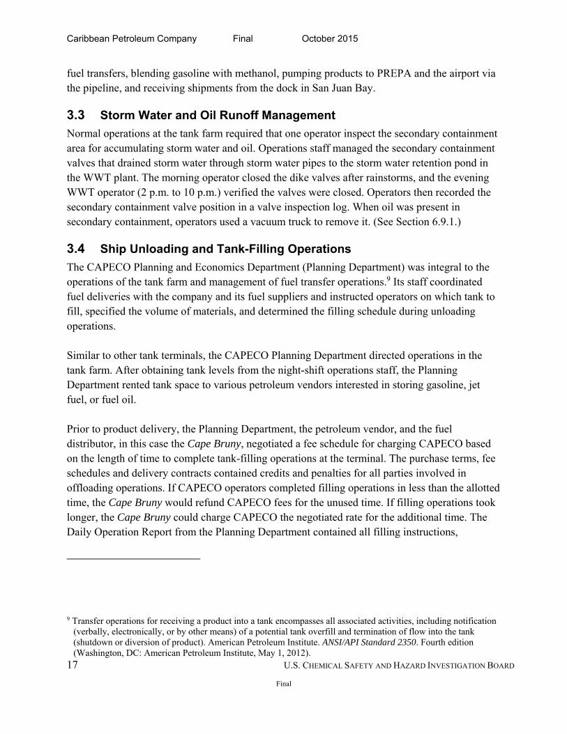
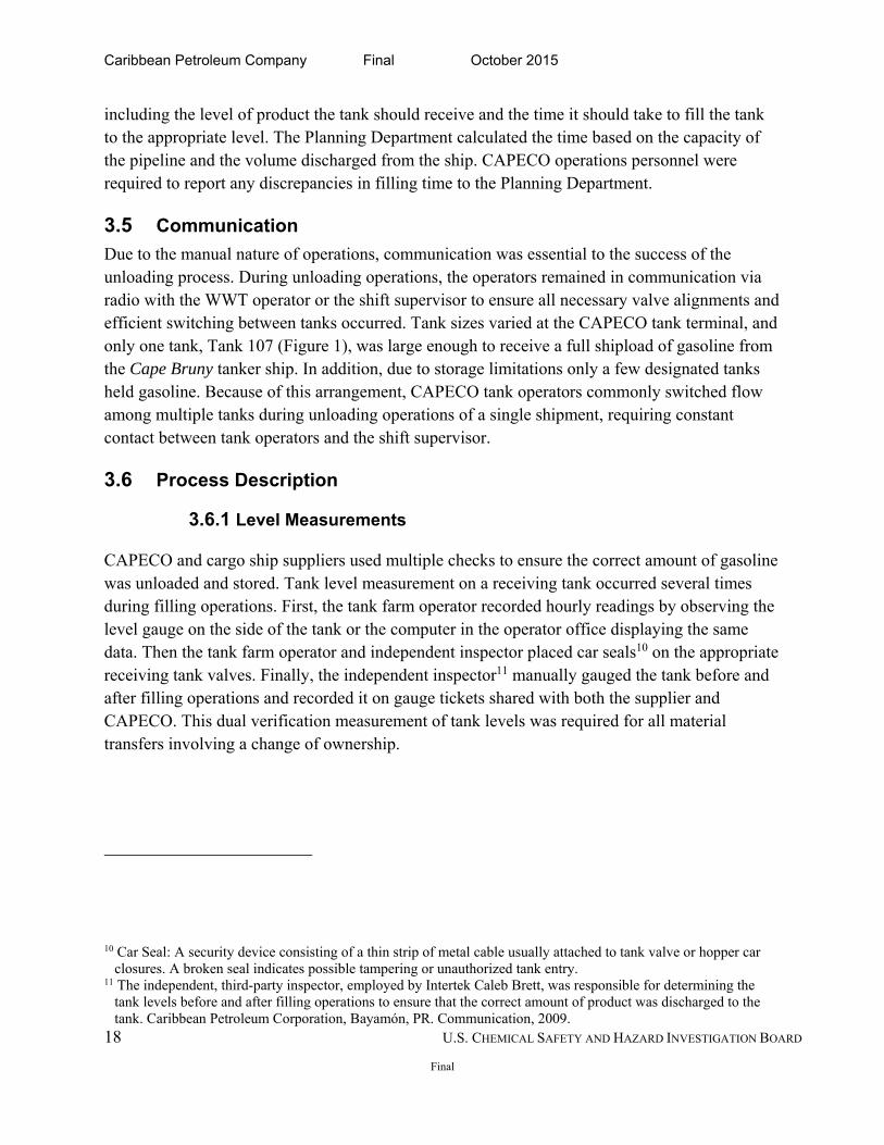
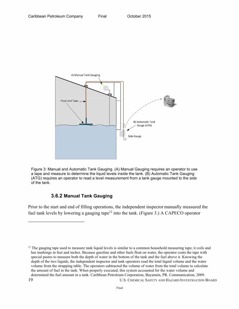
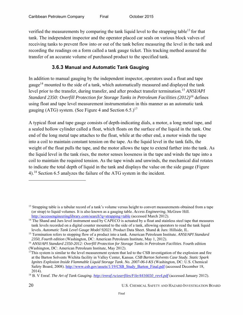
Prior to the start and end of filling operations, the independent inspector manually measured the fuel tank levels by lowering a gauging tape12 into the tank. (Figure 3.) A CAPECO operator
12 The gauging tape used to measure tank liquid levels is similar to a common household measuring tape; it coils and has markings in feet and inches. Because gasoline and other fuels float on water, the operator coats the tape with special pastes to measure both the depth of water in the bottom of the tank and the fuel above it. Knowing the depth of the two liquids, the independent inspector and tank operators read the total liquid volume and the water volume from the strapping table. The operators subtracted the volume of water from the total volume to calculate the amount of fuel in the tank. When properly executed, this system accounted for the water volume and determined the fuel amount in a tank. Caribbean Petroleum Corporation, Bayamón, PR. Communication, 2009.
Figure 3: Manual and Automatic Tank Gauging. (A) Manual Gauging requires an operator to use a tape and measure to determine the liquid levels inside the tank. (B) Automatic Tank Gauging (ATG) requires an operator to read a level measurement from a tank gauge mounted to the side of the tank.
Caribbean Petroleum Company Final October 2015
20 U.S. CHEMICAL SAFETY AND HAZARD INVESTIGATION BOARD
Final
verified the measurements by comparing the tank liquid level to the strapping table13 for that tank. The independent inspector and the operator placed car seals on various block valves of receiving tanks to prevent flow into or out of the tank before measuring the level in the tank and recording the readings on a form called a tank gauge ticket. This tracking method assured the transfer of an accurate volume of purchased product to the specified tank.
3.6.3 Manual and Automatic Tank Gauging
In addition to manual gauging by the independent inspector, operators used a float and tape gauge14 mounted to the side of a tank, which automatically measured and displayed the tank level prior to the transfer, during transfer, and after product transfer termination.15 ANSI/API Standard 2350: Overfill Protection for Storage Tanks in Petroleum Facilities (2012)16 defines using float and tape level measurement instrumentation in this manner as an automatic tank gauging (ATG) system. (See Figure 4 and Section 6.5.)17 A typical float and tape gauge consists of depth-indicating dials, a motor, a long metal tape, and a sealed hollow cylinder called a float, which floats on the surface of the liquid in the tank. One end of the long metal tape attaches to the float, while at the other end, a motor winds the tape into a coil to maintain constant tension on the tape. As the liquid level in the tank falls, the weight of the float pulls the tape, and the motor allows the tape to extend farther into the tank. As the liquid level in the tank rises, the motor senses looseness in the tape and winds the tape into a coil to maintain the required tension. As the tape winds and unwinds, the mechanical dial rotates to indicate the total depth of liquid in the tank and displays the value on the side gauge (Figure 4).18 Section 6.5 analyzes the failure of the ATG system in the incident.
13 Strapping table is a tabular record of a tank’s volume versus height to convert measurements obtained from a tape (or strap) to liquid volumes. It is also known as a gauging table. Access Engineering, McGraw Hill. http://accessengineeringlibrary.com/search?q=strapping+table (accessed March 2012).
14 The Shand and Jurs level instrument used by CAPECO is actuated by a float and stainless steel tape that measures tank levels recorded on a digital counter mounted to the side of a tank, allowing operators to read the tank liquid levels. Automatic Tank Level Gauge Model 92021. Product Data Sheet. Shand & Jurs: Hillside, IL.
15 Termination refers to stopping flow of a product into a tank. American Petroleum Institute. ANSI/API Standard 2350, Fourth edition (Washington, DC: American Petroleum Institute, May 1, 2012).
16 ANSI/API Standard 2350-2012: Overfill Protection for Storage Tanks in Petroleum Facilities. Fourth edition (Washington, DC: American Petroleum Institute, May 2012). 17This system is similar to the level measurement system that led to the CSB investigation of the explosion and fire
at the Barton Solvents Wichita facility in Valley Center, Kansas. CSB Barton Solvents Case Study. Static Spark Ignites Explosion Inside Flammable Liquid Storage Tank. No. 2007-06-I-KS (Washington, DC: U.S. Chemical Safety Board, 2008). http://www.csb.gov/assets/1/19/CSB_Study_Barton_Final.pdf (accessed December 18, 2014).
18 B. V Enraf. The Art of Tank Gauging. http://enraf.ru/userfiles/File/4416650_rev4.pdf (accessed January 2012).
Caribbean Petroleum Company Final October 2015
21 U.S. CHEMICAL SAFETY AND HAZARD INVESTIGATION BOARD
Final
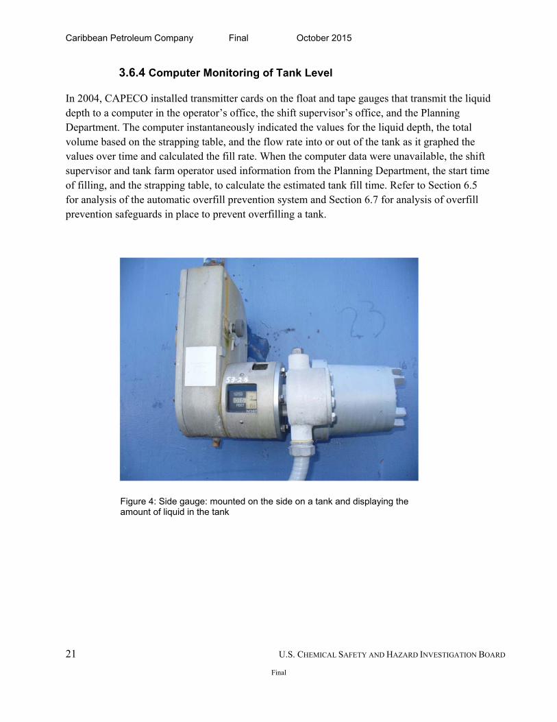
3.6.4 Computer Monitoring of Tank Level
In 2004, CAPECO installed transmitter cards on the float and tape gauges that transmit the liquid depth to a computer in the operator’s office, the shift supervisor’s office, and the Planning Department. The computer instantaneously indicated the values for the liquid depth, the total volume based on the strapping table, and the flow rate into or out of the tank as it graphed the values over time and calculated the fill rate. When the computer data were unavailable, the shift supervisor and tank farm operator used information from the Planning Department, the start time of filling, and the strapping table, to calculate the estimated tank fill time. Refer to Section 6.5 for analysis of the automatic overfill prevention system and Section 6.7 for analysis of overfill prevention safeguards in place to prevent overfilling a tank.
Figure 4: Side gauge: mounted on the side on a tank and displaying the amount of liquid in the tank
Caribbean Petroleum Company Final October 2015
22 U.S. CHEMICAL SAFETY AND HAZARD INVESTIGATION BOARD
Final
4.0 INCIDENT DESCRIPTION
4.1 Physical Cause
On Wednesday, October 21, 2009, the Cape Bruny cargo ship arrived at the CAPECO dock in San Juan Bay to unload CAPECO’s near-weekly shipment of more than 11.5 million gallons of unleaded gasoline. CAPECO assigned four personnel and three contract employees to assist in offloading gasoline from the Cape Bruny to various tanks on site. Only Tank 107 with a capacity of 21 million gallons was large enough to hold a full shipment of gasoline, but it was already holding product. As a result, CAPECO planned to pump the gasoline shipment to four smaller storage tanks (405, 504, 409, and 411) and the balance to Tank 107, expecting the filling to take more than 24 hours (Figure 1). One CAPECO operator was overseeing transfer operations at the dock, while another was monitoring the gasoline delivery at the terminal. See Appendix A, Incident Timeline. According to testimony and CAPECO records, shortly after noon on October 22, Tank 411 valve was fully opened but operations staff closed the valve to Tank 504 after observing the level gauge was physically stuck. Operators then fully opened the valve on Tank 409 and partially cracked the valve on Tank 411 directing more than 7,000 gallons of gasoline per minute into Tank 409 and allowing a small flow into Tank 411. At approximately 6:30 p.m., the operator manually calculated that Tank 409 would reach maximum fill sometime between 9 p.m. and 10 p.m., during shift change. To avoid complications during shift change, the operator fully opened the valve on Tank 411 and almost completely closed the valve on Tank 409. CAPECO operators often did not rely on the information displayed on the computer because the transmitters were frequently out of service. Therefore, under normal operation, operators manually recorded the hourly readings. On the night of the incident, the transmitter on Tank 409 was not sending level data measurements to the computer. At 10 p.m., as Tank 411 reached maximum capacity and was closed, operators fully opened the valve on Tank 409. One operator then read the level on the Tank 409 side gauge and reported it to his supervisor, who estimated that the tank would be full at 1 a.m.
Caribbean Petroleum Company Final October 2015
23 U.S. CHEMICAL SAFETY AND HAZARD INVESTIGATION BOARD
Final
At the 11 p.m. walk-around, the tank farm operator observed the side gauge on Tank 409 during his hourly check. The operator called the level into the supervisor who calculated once again that the tank should be full at 1 a.m.; however, between the 11 p.m. and 12 a.m. check, Tank 409 began to overflow. At the 12 a.m. check, operations staff noticed a fog on the ground and on the road along Tanks 504, 411 and 409. Fuel gushed from the vents, creating a spray of gasoline that formed a vapor cloud and pooled in the secondary containment dike. At midnight, the tank farm operator started to perform the hourly check of Tank 409, but before reaching the tank, he observed a vapor cloud and a strong smell of gasoline. He contacted the dock operator to halt the flow of gasoline to the tank and notified the WWT operator and his supervisor to meet at the western edge of the terminal. Despite the lack of illumination, they observed a white fog approximately three feet above the ground but could not hear or see gasoline overflowing from the vents on Tank 409 due to lack of lighting and the topography of the tank farm.19 As they approached the fog, the men noticed the air cool as the fog condensed on their hands, despite the 79ºF temperature. Noting the potential danger, the supervisor sent one operator to the security gate, while the supervisor and another operator drove around the facility attempting to find the source of the leak and developing vapor cloud.
At 12:23 a.m., on October 23, 2009, security cameras at CAPECO and neighboring facilities recorded the ignition of the vapor cloud in the WWT area. About seven seconds after ignition, the vapor cloud exploded, creating a pressure wave that damaged hundreds of homes and businesses up to 1.25 miles from the site. The fire propagated through the vapor cloud and ignited multiple subsequent tank explosions registering 2.9 on the Richter scale.20
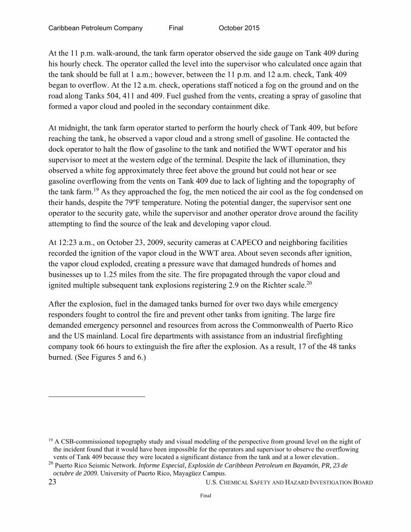
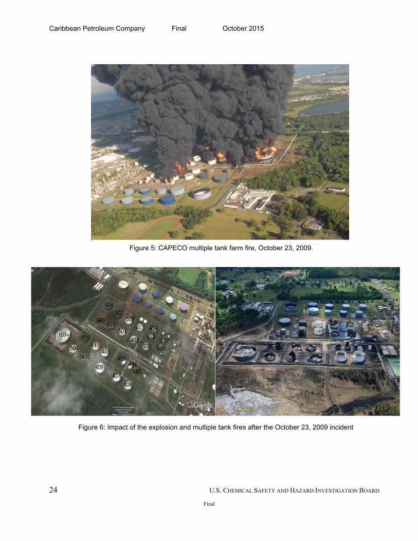
After the explosion, fuel in the damaged tanks burned for over two days while emergency responders fought to control the fire and prevent other tanks from igniting. The large fire demanded emergency personnel and resources from across the Commonwealth of Puerto Rico and the US mainland. Local fire departments with assistance from an industrial firefighting company took 66 hours to extinguish the fire after the explosion. As a result, 17 of the 48 tanks burned. (See Figures 5 and 6.)
19 A CSB-commissioned topography study and visual modeling of the perspective from ground level on the night of the incident found that it would have been impossible for the operators and supervisor to observe the overflowing vents of Tank 409 because they were located a significant distance from the tank and at a lower elevation..
20 Puerto Rico Seismic Network. Informe Especial, Explosión de Caribbean Petroleum en Bayamón, PR, 23 de octubre de 2009. University of Puerto Rico, Mayagüez Campus.
Caribbean Petroleum Company Final October 2015
24 U.S. CHEMICAL SAFETY AND HAZARD INVESTIGATION BOARD
Final
Figure 6: Impact of the explosion and multiple tank fires after the October 23, 2009 incident
Figure 5: CAPECO multiple tank farm fire, October 23, 2009.
Caribbean Petroleum Company Final October 2015
25 U.S. CHEMICAL SAFETY AND HAZARD INVESTIGATION BOARD
Final
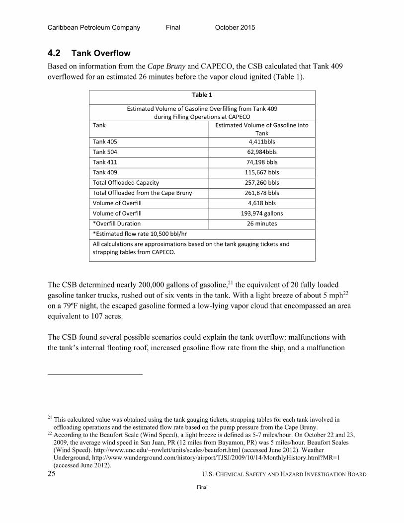
4.2 Tank Overflow
Based on information from the Cape Bruny and CAPECO, the CSB calculated that Tank 409 overflowed for an estimated 26 minutes before the vapor cloud ignited (Table 1).
Table 1
Estimated Volume of Gasoline Overfilling from Tank 409 during Filling Operations at CAPECO
Tank Estimated Volume of Gasoline into Tank
Tank 405 4,411bbls
Tank 504 62,984bbls
Tank 411 74,198 bbls
Tank 409 115,667 bbls
Total Offloaded Capacity 257,260 bbls
Total Offloaded from the Cape Bruny 261,878 bbls
Volume of Overfill 4,618 bbls
Volume of Overfill 193,974 gallons
*Overfill Duration 26 minutes
*Estimated flow rate 10,500 bbl/hr
All calculations are approximations based on the tank gauging tickets and strapping tables from CAPECO.
The CSB determined nearly 200,000 gallons of gasoline,21 the equivalent of 20 fully loaded gasoline tanker trucks, rushed out of six vents in the tank. With a light breeze of about 5 mph22 on a 79ºF night, the escaped gasoline formed a low-lying vapor cloud that encompassed an area equivalent to 107 acres. The CSB found several possible scenarios could explain the tank overflow: malfunctions with the tank’s internal floating roof, increased gasoline flow rate from the ship, and a malfunction
21 This calculated value was obtained using the tank gauging tickets, strapping tables for each tank involved in offloading operations and the estimated flow rate based on the pump pressure from the Cape Bruny.
22 According to the Beaufort Scale (Wind Speed), a light breeze is defined as 5-7 miles/hour. On October 22 and 23, 2009, the average wind speed in San Juan, PR (12 miles from Bayamon, PR) was 5 miles/hour. Beaufort Scales (Wind Speed). http://www.unc.edu/~rowlett/units/scales/beaufort.html (accessed June 2012). Weather Underground, http://www.wunderground.com/history/airport/TJSJ/2009/10/14/MonthlyHistory.html?MR=1 (accessed June 2012).
Caribbean Petroleum Company Final October 2015
26 U.S. CHEMICAL SAFETY AND HAZARD INVESTIGATION BOARD
Final
with the side gauge in addition to many systemic failures in CAPECO’s safety management system. See Section 6.0 for incident analysis.
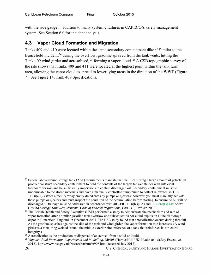
4.3 Vapor Cloud Formation and Migration
Tanks 409 and 410 were located within the same secondary containment dike.23 Similar to the Buncefield incident,24 during the overflow, gasoline sprayed from the tank vents, hitting the Tank 409 wind girder and aerosolized, 25 forming a vapor cloud. 26 A CSB topographic survey of the site shows that Tanks 409 and 411 were located at the highest point within the tank farm area, allowing the vapor cloud to spread to lower lying areas in the direction of the WWT (Figure 7). See Figure 14, Tank 409 Specifications.
23 Federal aboveground storage tank (AST) requirements mandate that facilities storing a large amount of petroleum product construct secondary containment to hold the contents of the largest tank/container with sufficient freeboard for rain and be sufficiently impervious to contain discharged oil. Secondary containment must be impermeable to the stored materials and have a manually controlled sump pump to collect rainwater. 40 CFR 112.8(c )(2) states a facility “may empty diked areas by pumps or ejectors; however, you must manually activate these pumps or ejectors and must inspect the condition of the accumulation before starting, to ensure no oil will be discharged.” Drainage must be addressed in accordance with 40 CFR 112.8(b )(1-5) and 112.8(c)(3) i-iv Above Ground Storage Tank Requirements, Code of Federal Regulations, Part 112, Title 40, 2002.
24 The British Health and Safety Executive (HSE) performed a study to demonstrate the mechanism and rate of vapor formation after a similar gasoline tank overflow and subsequent vapor cloud explosion at the oil storage depot in Buncefield, England, in December 2005. The HSE study found that aerosolization occurs during free fall. As the gasoline splashes against the side of the tank and wind girder, the vapor formation rate increases. (A wind girder is a metal ring welded around the middle exterior circumference of a tank that reinforces its structural integrity.)
25 Aerosolization is the production or dispersal of an aerosol from a solid or liquid. 26 Vapour Cloud Formation Experiments and Modelling. RR908 (Harpur Hill, UK: Health and Safety Executive,
2012). http://www.hse.gov.uk/research/rrhtm/rr908.htm (accessed July 2012).
Caribbean Petroleum Company Final October 2015
27 U.S. CHEMICAL SAFETY AND HAZARD INVESTIGATION BOARD
Final
Figure 7. Topographic Survey of CAPECO Tank Farm showing the gasoline vapor cloud migration from higher elevation (Tank 409-Red and Tank 411-Blue) toward low-lying areas by the WWT plant, the south eastern end of the refinery and wetlands to the north. The cloud indicates the approximate area where the vapor cloud migrated based on surveillance footage.
4.4 Open Dike Drain Valves
Although the October 22, 2009, secondary containment valve inspection log indicated that the dike valve for Tank 409 was closed, the CSB determined that the valve was open after the incident.27 The open dike valve directed gasoline to the storm water retention pond located in the WWT area where the large surface area pond provided a second location for gasoline to collect and vaporize. Refer to Section 6.9 for dike valve and human factors analysis.
27 CSB investigators tested the dike valve after the incident by pouring water into the dike area of Tank 409 and observed the flow to the storm water retention pond in the WWT area through the underground storm water channel.
Caribbean Petroleum Company Final October 2015
28 U.S. CHEMICAL SAFETY AND HAZARD INVESTIGATION BOARD
Final
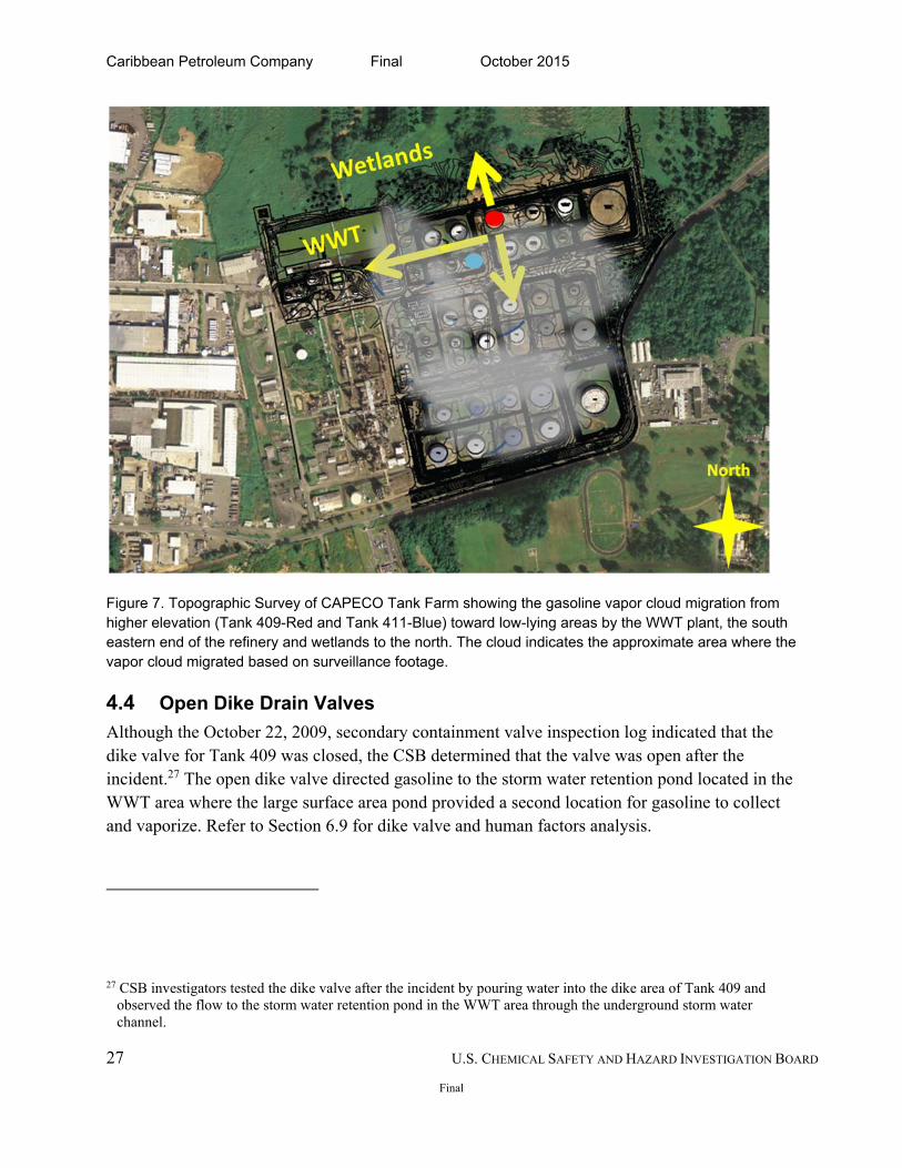
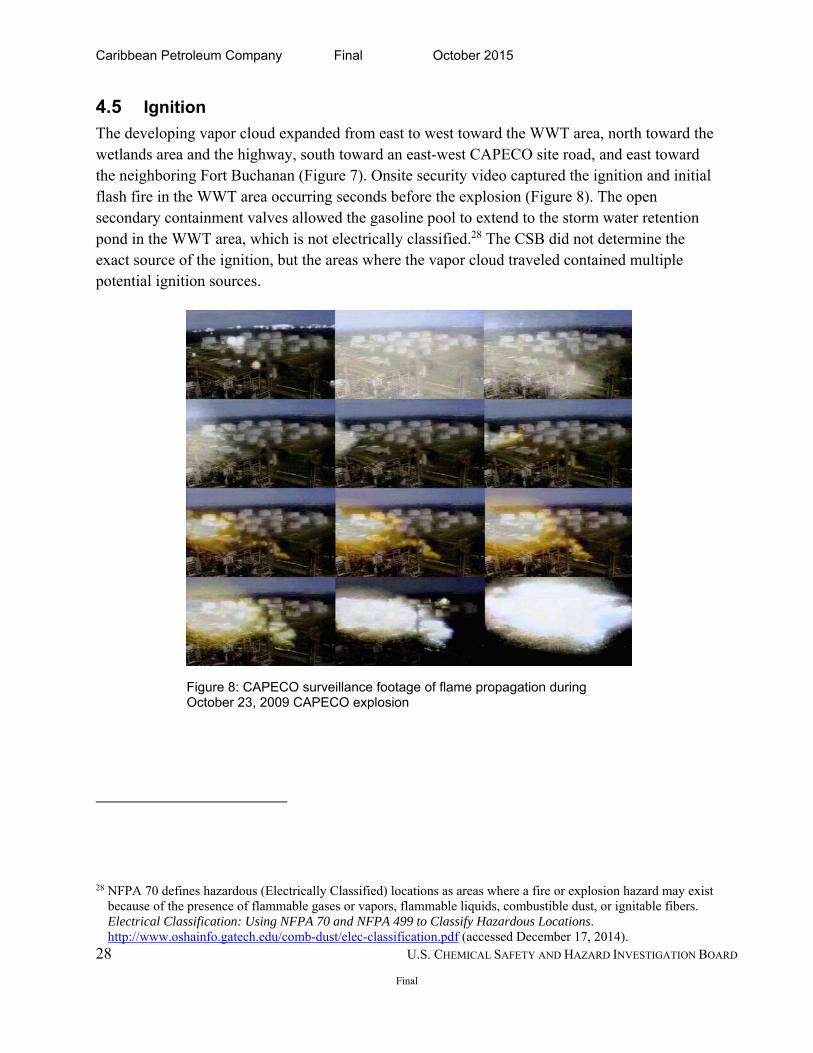
4.5 Ignition
The developing vapor cloud expanded from east to west toward the WWT area, north toward the wetlands area and the highway, south toward an east-west CAPECO site road, and east toward the neighboring Fort Buchanan (Figure 7). Onsite security video captured the ignition and initial flash fire in the WWT area occurring seconds before the explosion (Figure 8). The open secondary containment valves allowed the gasoline pool to extend to the storm water retention pond in the WWT area, which is not electrically classified.28 The CSB did not determine the exact source of the ignition, but the areas where the vapor cloud traveled contained multiple potential ignition sources.
28 NFPA 70 defines hazardous (Electrically Classified) locations as areas where a fire or explosion hazard may exist because of the presence of flammable gases or vapors, flammable liquids, combustible dust, or ignitable fibers. Electrical Classification: Using NFPA 70 and NFPA 499 to Classify Hazardous Locations. http://www.oshainfo.gatech.edu/comb-dust/elec-classification.pdf (accessed December 17, 2014).
Figure 8: CAPECO surveillance footage of flame propagation during October 23, 2009 CAPECO explosion
Caribbean Petroleum Company Final October 2015
29 U.S. CHEMICAL SAFETY AND HAZARD INVESTIGATION BOARD
Final
5.0 EMERGENCY RESPONSE
5.1 Response Description
Forty-three organizations responded to the incident, including federal, commonwealth, and nongovernmental organizations. The large number of responding agencies made communication difficult because the incident commander and the Unified Command Post changed frequently when different agencies claimed priority jurisdiction. The Bayamón and Cataño Fire Departments first arrived at the front gate of CAPECO at approximately 12:30 a.m. on October 23, 2009. At that time the fire had extended to approximately 103 acres (1,500 feet by 1,500 feet) of the tank farm, but firefighters were prohibited from entering the site until CAPECO safety personnel and the site fire chief arrived approximately 45 minutes later. Upon entering the facility, firefighters discovered that CAPECO lacked the necessary firefighting equipment to fight multiple tank fires at once. They found worn or missing fire hoses, stationary fire monitors without sufficient pressure to reach the tops of tanks, and insufficient equipment to provide the large quantities of foam necessary to control a fire of this magnitude.
Furthermore, CAPECO personnel and local firefighters were trained only for a worst-case scenario involving one tank on fire, rather than 11 tank fires at the same time caused by a vapor cloud explosion. Without sufficient equipment or training, local responders attempted to fight the multiple tank fires but failed as the fire encompassed more tanks.
The incident caused the governor of Puerto Rico to request federal assistance, and on October 24, 2009, the President signed an emergency declaration29 providing assistance for the municipalities of Bayamón, Cataño, Guaynabo, San Juan, and Toa Baja (Figure 9). The federal emergency declaration activated 17 FEMA Emergency Support Function Annexes (ESF)30 and enabled FEMA to provide logistical support, Direct Federal Assistance (DFA), and public assistance grants to state and local municipalities.31 Logistical support included setting up a more
29 On October 24, 2009, President Obama signed FEMA-3306-EM-PR for Category B (emergency measures) Direct Federal Assistance (DFA).
30 During an Emergency Declaration, FEMA has jurisdiction to release funding under its 17 FEMA Emergency Support Function Annexes. The ESFs provides structure and support for coordinating a federal interagency response to an incident. Emergency Support Function Annexes (Washington, DC: U.S. Federal Emergency Management Agency, 2008).
31 Through the Emergency Declaration request, Puerto Rico also requested DFA because it lacked the resources to handle the event. Under the Stafford Act, DFA states that the President can authorize 100% federal funding for emergency work: debris cleanup and/or removal; provision of food, water, ice, and other consumable commodities; and other emergency protective measures, under sections 403 and 407. The President also authorized the state and municipalities affected by the incident to be reimbursed for emergency protection measures through FEMA’s Public Assistance (PA) grant programs.
Caribbean Petroleum Company Final October 2015
30 U.S. CHEMICAL SAFETY AND HAZARD INVESTIGATION BOARD
Final
than 400-person Incident Command Post to assist state and federal agencies and to circulate information to the media and respond to public inquiries. In addition to the 530 firefighters and other responding agencies, approximately 900 National Guard personnel provided support in firefighting efforts, transportation, security, and environmental assessments. These efforts continued until Sunday, October 25, 2009, at 11:30 a.m., when the fires were extinguished.32 Ultimately, FEMA provided over $3.4 million33 to 27 entities for response efforts during and after the incident.
5.2 Response Assessment
The CSB found the following shortcomings in the emergency response to the CAPECO incident, many of which were also identified in the FEMA After Action Report,34 compiled after the incident.
Insufficient equipment. Tank terminals like CAPECO are not considered high-hazard facilities under existing EPA and OSHA regulations;35 therefore, they are not required to conduct a risk analysis where they consider the potential of a vapor cloud explosion and multiple tank fires. Neither CAPECO nor the fire department had the requisite amount of foam and adequate equipment to effectively fight and control a fire involving multiple tanks.
Insufficient preplanning with local fire departments or firefighter training at the site level. CAPECO did not preplan with local emergency responders, set up mutual aid with other hazardous materials sites, or adequately train facility personnel to address a tank farm fire involving multiple tanks. The CSB found that after the refinery shut down in 2000, the facility curtailed investment into its firefighting operations on-site. In fact, training for CAPECO personnel was limited only to fighting a fire involving one tank, not an incident involving multiple tanks.
Limited emergency preparedness. Local fire departments did not have sufficient training or resources to respond to industrial fires and explosions, which resulted in firefighting delays from insufficient foam and equipment. The limited training and resources of the local fire
32 The PR Fire Department extinguished the fires with assistance from a contractor that specialized in tank farm firefighting.
33 Summary of Declaration Report: Public Assistance Program (Washington, DC: U.S. Federal Emergency Management Agency, June 11, 2012).
34 Caribbean Petroleum Corporation (CaPeCo) / Gulf Refinery Explosion After Action Report (AAR). FEMA 3306-EM-PR. October 23-26, 2009 (Washington, DC: U.S. Federal Emergency Management Agency, 2010).
35 EPA considers facilities as CAPECO as a “significant and substantial harm facility” under the Facility Response Plan regulations. See Section 8.6.6 for further discussion.
Caribbean Petroleum Company Final October 2015
31 U.S. CHEMICAL SAFETY AND HAZARD INVESTIGATION BOARD
Final
departments resulted in an inefficient firefighting operation. The fires were not extinguished until an industrial firefighting company suppressed the last of the tank fires. FEMA’s After Action Report identified additional training and exercises for the Incident Management Team on an all-hazards approach to improve the initial multiagency response and recovery.
Overlapping multi-agency, multi-jurisdictional response. Forty-three federal, commonwealth, and nongovernmental organizations responded to the incident.36 As new agencies arrived, the person in the Incident Commander role changed without following the Incident Command System/National Incident Management System (ICS/NIMS). For example, the Puerto Rico Emergency Management Agency (PREMA) operated using ICS/NIMS, whereas the PR National Guard conducted operations using military standards.37 FEMA’s After Action Report also identified poor integration of Unified Command with the National Guard and PREMA after the Governor’s office declared the emergency. The report further emphasized the need for additional joint training and exercises to improve the integration of the ICS with the NIMS. The FEMA report also calls for the development of Mass Fatality and Mass Casualty plans to address catastrophic incidents.
5.3 Incident Impact
5.3.1 Community Impact
Despite approximately 1,600 people residing adjacent to the CAPECO facility in the Puente Blanco community38 and about 48,500 residents living in Cataño three miles from the incident site (Figure 9), the 2009 explosion and fires did not result in any fatalities. However, shrapnel and glass from the blast caused minor injuries to three people at Fort Buchanan. Nearby residents of the surrounding communities were awakened by the blast and ensuing fire. The CSB learned, regulatory authorities in Puente Blanco issued unclear evacuation orders by bullhorn as they drove through the community. With no planned evacuation routes or shelters, residents crowded into the narrow streets. Some members of other nearby communities evacuated voluntarily to escape damaged homes and potential health effects from the smoke and vapors generated by the fire.
36 Caribbean Petroleum Corporation (CaPeCo) / Gulf Refinery Explosion After Action Report (AAR). FEMA 3306-EM-PR, October 23-26 2009 (Washington, DC: U.S. Federal Emergency Management Agency, 2010): 9.9.
37 Ibid., p.6. 38 Ibid., p.4.
Caribbean Petroleum Company Final October 2015
32 U.S. CHEMICAL SAFETY AND HAZARD INVESTIGATION BOARD
Final
Fort Buchanan experienced the most severe damage—suffering an estimated $5 million in repair costs. Community impact assessments39 found most of the structural damage occurred in the Puente Blanco neighborhood where PREMA and the Department of Housing (DOH) found damage to 232 of the 266 homes assessed; 139 were repaired and six were demolished by November 2009.40 The Puente Blanco community also experienced environmental contamination to several surface water bodies, including federally protected wetlands and streams surrounding the CAPECO site. After assessing 289 homes damaged by the explosion in the Cataño community, the Small Business Administration (SBA)41 designated 25 single-family homes as destroyed or severely damaged at or beyond 40% of their fair market value. (See Figure 10.)
Figure 9: Communities neighboring the CAPECO facility
39 The Small Business Administration (SBA), in conjunction with the PR Emergency Management Agency (PREMA) and the PR Department of Housing (DOH), conducted community assessments after the incident.
40 Federal Emergency Management Agency. Caribbean Petroleum Corporation (CaPeCo) / Gulf Refinery Explosion After Action Report (AAR). FEMA 3306-EM-PR. October 23 – 26, 2009 Incident Recovery Activities Summary: Caribbean Petroleum Corporation Fuel Explosion (November 18, 2009).
41 The SBA’s mission is to help disaster-stricken communities through direct loans to businesses, homes, and non -profit organizations. SBA Disaster Recovery Plan. https://www.sba.gov/content/disaster-recovery-plan (accessed December 19, 2014).
Caribbean Petroleum Company Final October 2015
33 U.S. CHEMICAL SAFETY AND HAZARD INVESTIGATION BOARD
Final
Figure 10: Community damage surrounding the CAPECO facility
Figure 11: Oil Spill into nearby wetlands (photo from NOAA.gov) and in a local community drain after CAPECO explosion and tank fires
Caribbean Petroleum Company Final October 2015
34 U.S. CHEMICAL SAFETY AND HAZARD INVESTIGATION BOARD
Final
5.4 Impact to the Commonwealth
The incident forced the Commonwealth government and local officials to evacuate approximately 3,000 people in a nearby prison and other government facilities. Changing wind patterns caused the governor to prepare for the evacuation of over 30,000 individuals likely affected by particulate fallout from the smoke plume that extended miles out to sea. Overall, approximately 600 people used the shelters in Cataño, Guaynabo, and Toa Baja.42
5.5 Environmental Impact
The CAPECO incident released thousands of gallons of oil, fire suppression foam, and contaminated runoff to Malaria Creek, which traverses the Puente Blanco community to the San Juan Bay. CAPECO and the EPA collected and shipped offsite an estimated 171,000 gallons of oil and 22 million gallons of contact water.43, 44 Overall, approximately 30 million gallons of petroleum was released via storm water channels, on-site and off-site surface water bodies, and neighboring wetlands to San Juan Bay.45 Environmental assessments jointly conducted by the EPA, the US Fish and Wildlife Service (USFWS), and the Puerto Rico Department of Natural Resources (PR DNR) found dead wildlife and both aquatic and avian species, including several legally protected species, covered in oil.46 (Figure 11.)
5.6 Impact to Transportation and Commerce
The incident also disrupted commerce and transportation corridors on the ground and in the air in the San Juan area. A main interstate, PR-22, was closed for three days, limiting access to work and shopping malls and interrupting transportation of goods to and from the main port. The smoke plume also resulted in airspace interruptions and temporary flight restrictions for the Luis Muñoz Marín International Airport. The explosion caused many tourists in the San Juan area to
42 Caribbean Petroleum Corporation (CaPeCo) / Gulf Refinery Explosion After Action Report (AAR). FEMA 3306-EM-PR. October 23-26, 2009. (Washington, DC: U.S. Federal Emergency Management Agency, 2010): 11.
43 Contact water contains petroleum product. 44 C. Jimenez, K. Glenn, G. Denning. International Oil Spill Conference Proceedings, 2011 (1).
http://ioscproceedings.org/doi/pdf/10.7901/2169-3358-2011-1-90 (accessed December 19, 2014). 45 Environmental Protection Agency. Securing Cleanup from ashes at the Puma Energy Caribe Site. 2014.
http://www2.epa.gov/enforcement/case-study-cleanup-puma-energy-caribe-site-puerto-rico (accessed May 4, 2015).
46 C. Jimenez, K. Glenn, G. Denning. International Oil Spill Conference Proceedings, 2011 (1). http://ioscproceedings.org/doi/pdf/10.7901/2169-3358-2011-1-90 (accessed December 19, 2014).
Caribbean Petroleum Company Final October 2015
35 U.S. CHEMICAL SAFETY AND HAZARD INVESTIGATION BOARD
Final
flee, affecting the local economy. The total economic and psychological effects of these major disruptions have not been determined.47
5.7 Impact of Overfill Incident on CAPECO
In May 2010, CAPECO was required to pay more than $8.2 million for environmental liabilities associated with the Bayamón petroleum distribution facility and the 170 service stations it owned and leased under a settlement agreement.48 In the same month, the EPA issued a Notice of Federal Assumption to take responsibility for the remaining cleanup at the CAPECO site.49
6.0 INCIDENT ANALYSIS
6.1 Systemic Failure at CAPECO Led to Failure of the Overfill Prevention System
The CSB determined that numerous technical and systemic failures contributed to the explosion and multiple tank fires at the CAPECO tank terminal. The CSB found that multiple layers of protection failed within the level control and monitoring system at the same time. In addition a lack of independent safeguards contributed to the overfill. James Reason’s Swiss Cheese Model best demonstrates these systemic failures that led to the accident.50 Reason postulates that an accident results from the breakdown of the “interaction between latent failures51 and a variety of local triggering events (active failures)”52 and although rare, the “adverse conjunction of several
47 Ibid. 48 United States Announces Bankruptcy Settlement with Oil Company in Wake of October 2009 Explosion and Fire.
(Washington, DC: U.S. Department of Justice, 2011) http://www.ju.tice.gov/opa/pr/2011/May/11-enrd-657.html (accessed December 19, 2014).
49 C. Jimenez, K. Glenn, G. Denning. International Oil Spill Conference Proceedings, 2011 (1) http://ioscproceedings.org/doi/pdf/10.7901/2169-3358-2011-1-90 (accessed December 19, 2014).
50 Reason postulated that “a multiplicity of overlapping and mutually supporting defenses” both hard and soft, allow complex systems to function despite a single technical or human failure. Hard defenses include technical devices such as automated engineered safety features, physical barriers, alarms and annunciators, interlocks, keys, personal protective equipment, non-destructive testing, and improved system design (Reason, 1997). Soft defenses rely heavily on a combination of paper and people, i.e., legislation, regulatory surveillance, rules and procedures, training, drills and briefings, administrative controls, licensing, certification, supervisory oversight, front-line operators (Reason, 1997).
51 Latent Failures arise from strategic and other top-level decisions made by governments, regulators, manufacturers, designers, and organizational managers. They include poor design, supervisory gaps, undetected manufacturing defects, maintenance failures, unworkable procedures, poor automation, inadequate training, and insufficient or inadequate tools and equipment. These failures can lay dormant in an organization for years and, if undetected or unfixed, can contribute to active failures by creating deviation from procedures (Reason, 1997).
52 Active failures are unsafe acts committed by those at the human-system interface or the sharp end of the system by personnel. They are immediate and have short-lived effects (Reason, 1997).
Caribbean Petroleum Company Final October 2015
36 U.S. CHEMICAL SAFETY AND HAZARD INVESTIGATION BOARD
Final
causal factors” from various layers.53 The deficiencies or holes at each layer of protection are constantly increasing or decreasing based on management decisions and operational deviations.54
Figure 12: Contributing to the October 2009 overfill incident at CAPECO were multiple failures of the level control and monitoring system in addition to a lack of safeguards like a high level alarm, an independent level alarm and an automatic overfill prevention system that allows for automatic shutdown or diversion.
6.1.1 Inadequate Safety Management System
The CSB found that the CAPECO overfill incident resulted from a combination of multiple deficiencies in the safety management system, including the breakdown in the level control and monitoring system within an inadequate safety management system and a lack of safeguards,55 such as an independent high-level alarm and an automatic overfill prevention system. In terminals, the level control system includes procedures and equipment used to control tank-filling operations. For many tank operations, the level control system is the operator and the alarm system, which together are able to control the fuel receiving process. In some cases, the
53 J. Reason. Human Error. (United Kingdom: Cambridge University Press, 1990). 54 J. Reason. Managing the Risks of Organizational Accidents (Brookfield: Ashgate, 1997). 55 Safeguards are any device, system, or action that would likely interrupt the chain of events following an initiating
event.
Caribbean Petroleum Company Final October 2015
37 U.S. CHEMICAL SAFETY AND HAZARD INVESTIGATION BOARD
Final
level control system is an automatic level controller functioning to restrict flow into the tank. The CSB finds that systemic failures at CAPECO included:
a history of poorly maintaining terminal operations;
an inherent financial pressure to fill the tanks within the Planning Department’s stipulated time, which was at odds with safety;
a failure to learn from previous overfill incidents at the facility;
a lack of preventative maintenance for the malfunctioning float and tape device, automatic tank gauge transmitters;
an unreliable computer for calculating tank fill times;
a lack of overfill prevention safeguards as an independent alarm;
a lack of formal procedures for tank-filling operations for operators and managers;
an insufficient mechanical integrity program for safety critical equipment;
poor adherence to human factors principles for safety critical equipment.
6.2 CAPECO History of Poorly Maintaining Terminal Operations
The CSB found that CAPECO had a history of poorly maintaining its terminal operations. EPA inspection records from 1992 to 2004 indicate a lack of investment in tank valves, maintenance of secondary containment around the tank farm, and appropriate level gauges and engineering controls. For the 12-year period, SPCC inspections revealed problems with leaking transfer valves, leaking product lines, insufficient secondary containment, failure to lock valves that could release content, and oil sheen present in dikes and adjacent dikes, indicating the migration of oil from a leak or spill through the dike drain valves that were unaddressed in subsequent inspections. Although these deficiencies were noted for smaller tanks holding less than 10,000 gallons of liquid and asphalt tanks not in the main tank farm, the SPCC records offer additional insight into how CAPECO management historically maintained the facility. Refer to Section 8.6.2 for CAPECO SPCC deficiencies.
6.3 Previous Spill Incidents at CAPECO
The CSB learned CAPECO had multiple overfills and spills during transfer operations. CAPECO records show a history of 15 separate incidents involving tanks of varying sizes from 1992 to 1999 and 3 others after 2005, when spills or overfills occurred during filling, draining, or transferring operations. Among the 15 incidents, 8 were overfills and 7 were spills. Incidents resulted from valves in the open position, tank gauge malfunctions, or corrosion of pipes or tank shells.
6.4 Normal Practice to Fill Tanks to Maximum Levels at Odds with Safety
The CSB found that despite the lack of computer-displayed tank levels, CAPECO operators received instructions from the Planning Department to fill the tanks to their maximum fill level during the October 21-23, 2009 filling operations, exposing the tank farm to the eventual
Caribbean Petroleum Company Final October 2015
38 U.S. CHEMICAL SAFETY AND HAZARD INVESTIGATION BOARD
Final
incident. The Planning Department coordinated fuel deliveries with fuel suppliers and instructed operators on which tank to fill, specified the volume of materials, and determined the filling schedule during unloading operations. (See Section 3.4.) The contractual obligation to fill the specified tanks in the allotted time or at a faster rate was at odds with safely conducting filling operations.
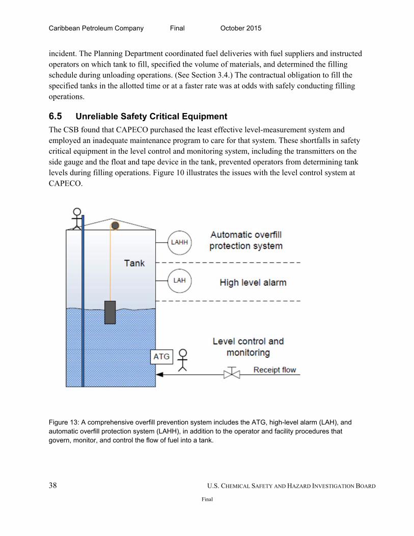
6.5 Unreliable Safety Critical Equipment
The CSB found that CAPECO purchased the least effective level-measurement system and employed an inadequate maintenance program to care for that system. These shortfalls in safety critical equipment in the level control and monitoring system, including the transmitters on the side gauge and the float and tape device in the tank, prevented operators from determining tank levels during filling operations. Figure 10 illustrates the issues with the level control system at CAPECO.
Figure 13: A comprehensive overfill prevention system includes the ATG, high-level alarm (LAH), and automatic overfill protection system (LAHH), in addition to the operator and facility procedures that govern, monitor, and control the flow of fuel into a tank.
Caribbean Petroleum Company Final October 2015
39 U.S. CHEMICAL SAFETY AND HAZARD INVESTIGATION BOARD
Final
6.5.1 Unreliable Level Control and Monitoring Systems
CAPECO lacked a reliable automatic level control and monitoring system for measuring tank levels. (See Figure 13.) The automatic gauging system at CAPECO, described in Section 3.6.3, had a history of repeated failures and prolonged out-of-service periods. On the night of the incident, the float and tape device inside Tank 504 became stuck and the transmitters for Tanks 107 and 409 were not receiving data from the side gauge on Tank 409; therefore, data on the tank liquid level and a calculated fill rate into 409 were not available in real time on the computer. The computer monitoring system was often compromised by outages from lightning strikes and accidental breakage of the computer cables after maintenance activities in the tank farm area. In addition, the transmitters56 that sent the data to the computer were also susceptible to electromagnetic interference and frequently needed replacing after lightning storms. Records show, CAPECO took weeks to replace the faulty transmitters. Therefore, CAPECO operators found the computer monitoring system to be unreliable. After completing hourly rounds, the operator reported the tank level back to the shift supervisor, who then manually calculated the time it would take to fill the tank. The CSB learned that CAPECO operators had been calculating the tank levels by hand for decades. This method of monitoring the level in the tanks was unreliable given the 15 prior tank spill incidents at the facility and the extended time that the level detection equipment remained out of service due to failure.
6.5.2 Float and Tape Gauges Prone to Failure
Float and tape gauges, which the aboveground storage tank industry has used for many years, are also prone to failure due to historically well-known design flaws.57 Mechanical friction in pulleys, spring motors, and indicators degrade measurement reliability, causing the system to indicate the liquid depth inaccurately.58 In addition, the gear mechanism attached to the indicator and transmitter can disengage, resulting in inaccurate readings, and can disrupt synchronization of the transmitter.59 The float tape gauge is also subject to “excessive wear and tear,”60 resulting from continuous and sudden movement from turbulence generated by the fuel in the tank.61
56 In accordance with ANSI/API Overfill Protection for Storage Tanks in Petroleum Facilities (ANSI/ANSI/API 2350), operators recalibrate the level transmitter when they note more than a 3-inch discrepancy in tank levels between the physical gauge reading and the float and tape reading recorded at the side gauge. (See section 8.10 for API discussion.)
57 B. V. Enraf. The Art of Tank Gauging. http://enraf.ru/userfiles/File/4416650_rev4.pdf (accessed January 2012). 58 Ibid. 59 Ibid. 60 Ibid. 61 Ibid.
Caribbean Petroleum Company Final October 2015
40 U.S. CHEMICAL SAFETY AND HAZARD INVESTIGATION BOARD
Final
6.5.3 Poor Float and Tape Gauge Maintenance
The CSB found the float and tape gauges installed on CAPECO tanks were poorly maintained. Installed in February 2004, the float and tape gauges were frequently out of service for multiple tanks at the same time. The CSB learned that just nine months after initial installation, CAPECO hired L&J Engineering to service the level transmitter due to “volume discrepancies,” and one month prior to the 2009 explosion, CAPECO hired contractors to calibrate the side gauge on numerous tanks in the tank terminal. The CSB found CAPECO’s lack of preventative maintenance62 resulted in the failure to repair the tank gauging system. A review of CAPECO maintenance logs found no status update on maintenance activities addressing a broken float tension on Tank 411 in July 2009, or on fixing strapping problems with Tanks 405 or 411 in early October 2009. During October 2009, the level transmitter for Tank 409 was out of service from the week prior, and maintenance personnel were waiting for repair parts. Despite frequent outages, CAPECO management did not replace the level transmitter on any of the tanks and relied only on the float and tape gauge located on the side of the tank to obtain tank levels.
The CSB found many of CAPECO’s tank gauging practices were contrary to the recommended practices in API Manual of Petroleum Measurement Standards (MPMS) Chapter 3.1A,63, 64 which might have contributed to inaccurately calculating liquid levels in Tank 409. Volume discrepancies in a tank could also arise from using a specific tank gauge, relying on a strapping table to calculate tank levels, and using unslotted still pipes.
62CCPS Guidelines for Safe Process Operations and Maintenance: “Preventative maintenance seeks to reduce the frequency and severity of unplanned outages by establishing a fixed schedule of routine inspection and service. The chief advantage of a preventative maintenance program is that it gives maintenance management the flexibility to plan and execute required equipment service with a minimum disruption of essential plant operations. The importance of preventative maintenance to process safety management cannot be overemphasized.” American Institute of Chemical Engineers, Center for Chemical Process Safety. Guidelines for Safe Process Operations and Maintenance (New York: Wiley & Sons, 1995).
63 American Petroleum Institute. Manual of Petroleum Measurement Standards, Chapter 3.1A, Standard Practice for the Manual Gauging of Petroleum and Petroleum Products, 3rd edition (August 2013).
64 The Manual of Petroleum Measurement Standards, Chapter 3.1A applies to liquids with a Reid vapor pressure. Reid vapor pressure is the property of a liquid fuel that defines its evaporation characteristics and a common measure of and generic term for gasoline volatility. http://www.epa.gov/otaq/fuels/gasolinefuels/volatility/index.htm.) of less than 103 kPa. A Pascal is the SI-derived unit of pressure, internal pressure, stress, Young’s modulus, and tensile strength. 1 Kilopascals (kPa) ≡ 1000 Pa. or 15 psia.
Caribbean Petroleum Company Final October 2015
41 U.S. CHEMICAL SAFETY AND HAZARD INVESTIGATION BOARD
Final
Type of gauge: CAPECO did not use an innage gauge, as recommended by the MPMS Chapter 3.1A, but relied on an outage gauge65 to obtain tank levels. The MPMS Chapter 3.1A recommends the use of innage gauges over outage gauges due to movement of the tank gauge reference point, but recognizes circumstances when outage gauges are more applicable. The MPMS Chapter 3.1A also recommends that facilities inspect both manual tape-and-bob assembly and portable electronic gauging devices daily for inconsistencies that may introduce error, and that they verify for accuracy at least annually. It also requires operations personnel to check the detection signal from the sensor/probe annually. The CSB did not find any inspection records demonstrating daily or annual float and tape checks at CAPECO.
Strapping table inaccuracies: API MPMS Ch. 3.1A advises that a volume discrepancy can arise from the inherent inaccuracies in strapping tables, which can lead to overestimating or underestimating of tank quantity, among other problems.
Calculating tank volume in the critical zone: According to API MPMS Ch. 3.1A, “computing tank volume in the critical zone66 is subject to considerable error.” Inaccuracies can also arise from strapping tape calibration or thermal expansion, tension of the strapping tape, correction of shell expansion due to liquid head (static head), measurement of shell plate thickness and calculation of deadwood.67
Using still pipes without slots: The independent inspector used a gauge hatch on the fixed roof and a gauging funnel on the floating roof to obtain liquid levels in Tank 409 but used an 8-inch still pipe68 to physically gauge Tank 107. According to API MPMS Ch. 3.1A, still pipes without slots can lead to “serious liquid height measurement, temperature determination, and sampling errors.”
65 An innage gauge is a direct measurement of the linear distance along a vertical path from the datum plate or tank bottom to the surface of the liquid being gauged. An outage gauge is an indirect measurement of the linear distance along a vertical path from the surface of the liquid being gauged to the tank reference gauge point.
66 The critical zone is the area where liquid is partially displaced by the roof between the point where the liquid just touches the lowest section of the roof and the point where the roof floats freely.
67 Deadwood refers to the ducted weight of all parts of a floating roof, including the swing joint, the drain and other items attached to the tank shell or bottom that are resting on the roof supports when the floating roof is immersed in liquid.
68 Still pipe is used to gauge liquid levels inside a tank. The reference gauge point is located on the upper lip, and the datum plate is located at the lower lip. Still pipes may have slots or be solid.
Caribbean Petroleum Company Final October 2015
42 U.S. CHEMICAL SAFETY AND HAZARD INVESTIGATION BOARD
Final
6.6 Lack of Formal Procedures for Tank Terminal Operations
The CSB learned that CAPECO’s standard operating procedures only addressed activities requiring a permit to work and did not cover terminal operations. When CAPECO became a fuel storage depot, it was no longer required to follow standards that would require regularly updated standard operating procedures (SOPs), such as OSHA PSM or EPA RMP. CAPECO last updated refinery SOPs to comply with PSM in 1999. In August 2009, CAPECO updated procedures that resulted in work permits (hot work, cold work, confined space, and lockout/tagout) but failed to update or write terminal operating procedures. The terminal often had activity outlines and checklists, but it did not have SOPs to instruct employees how to perform daily activities, such as discharging from a vessel or barge, gauging tanks, or operating dike drain valves. For example, CAPECO had a two-page document listing the activities to discharge from a vessel or barge, but the document did not provide details on how to perform the activities, who would be in charge, or what to do in an emergency. In addition, CAPECO lacked procedures dictating how to load multiple tanks at the same time. The normal practice of partially opening the tank valves of the next tank in line to be filled (See Section 6.9.4) directly influenced the tank fill rate, but the facility lacked procedures addressing the influence of valve cracking on calculating the tank fill time. As a result of the incident, the Puerto Rico Occupational Safety and Health Administration (PR OSHA) issued a serious violation to CAPECO for lacking tank filling procedures during transfer operations. See PR OSHA Section 8.8.
6.7 Lack of Additional Safeguards such as High-Level Alarms and an Automatic Overfill Prevention System
The CSB found that CAPECO tanks lacked effective safeguards to prevent a tank overfill. In addition to an accurate automatic tank gauging system with a reliable computer monitoring system, potential safeguards include independent high-level alarms, which give a visual or auditory indication when material in the tanks reach a specific high level, and an automated overfill prevention system,69 which allows for shutoff or flow diversion to prevent overfill. Tank 409 lacked an independent high level alarm.70 Without safety alarms and associated critical response procedures, CAPECO tank farm operators were left with a faulty level control and monitoring system to detect an overfill in Tank 409.
69 ANSI/ANSI/API 2350 defines an automated overfill prevention system (AOPS) as an overfill prevention system not requiring the intervention of operating personnel to function.
70 High-high level alarm: An alarm generated when the product level reaches the high tank level. American Petroleum Institute. ANSI/API Standard 2350-2012: Overfill Protection for Storage Tanks in Petroleum Facilities, fourth edition (Washington, DC: American Petroleum Institute, May 2012).
Caribbean Petroleum Company Final October 2015
43 U.S. CHEMICAL SAFETY AND HAZARD INVESTIGATION BOARD
Final
6.8 Other Potential Contributing Factors
The CSB found that other factors might have contributed to the accident, such as the construction and limitations of the Tank 409 internal floating roof and the variable flow rates and line pressures into Tank 409.
6.8.1 Internal Floating Roof Construction and Limitations
The destruction of the Tank 409 internal floating roof in the explosion prevented the CSB from determining if it failed during filling operations. Therefore, internal floating roof failure might have contributed to the overfilling of Tank 409. The roof construction of Tank 409 was subject to numerous operational limitations. Tank 409 had a fixed cone roof with an aluminum internal floating roof (IFR), and a freeboard71 of 12 feet (24,157 bbls). (See Figure 14 for Tank 409 specifications.) Aluminum IFRs are prone to corrosion when exposed to caustic liquids but sufficient for petroleum and organic materials. An internal floating roof can fail by means of turbulence,72 roof submersion,73 seal issues, and fatigue.74 API MPMS Ch. 3.1A discusses the impact of the floating roof on tank volume. On the night of the incident, the final reading likely occurred when the floating roof was floating freely. When floating roofs are in the free-floating position, they displace the amount of liquid equal to the weight of the roof and attached deadwood. The only accurate way to obtain volume in the critical zone is by a liquid calibration procedure. API MPMS Ch. 3.1A advises that facilities calculate roof displacement by considering the roof weight, temperature, and density of the liquid of tank contents in the critical zone. CAPECO did not calculate the roof displacement of Tank 409.
71 Freeboard is the vertical distance between the maximum liquid level and the top of the tank. 72 Turbulence: high velocity of receipt fluid sufficient to generate waves at the surface of the liquid causing floating
roofs to shake, move, and vibrate. Turbulence usually results from excessive receipt rates when the liquid level is low in the tank.
73 Roof Submersion: Part or the entire roof becomes covered with the stored tank product. 74 Fatigue is the creation of initiating cracks at discontinuities in steel structures resulting from stresses magnified
by “stress risers” or discontinuities from corrosion.
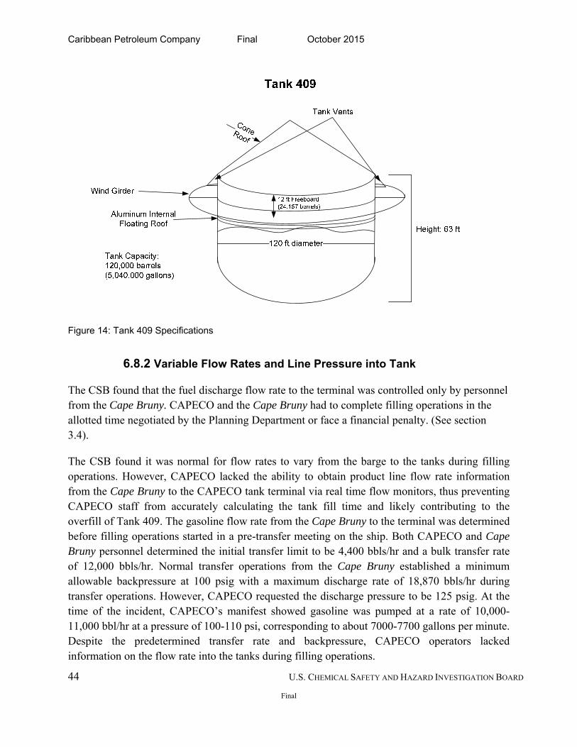
Caribbean Petroleum Company Final October 2015
44 U.S. CHEMICAL SAFETY AND HAZARD INVESTIGATION BOARD
Final
Figure 14: Tank 409 Specifications
6.8.2 Variable Flow Rates and Line Pressure into Tank
The CSB found that the fuel discharge flow rate to the terminal was controlled only by personnel from the Cape Bruny. CAPECO and the Cape Bruny had to complete filling operations in the allotted time negotiated by the Planning Department or face a financial penalty. (See section 3.4).
The CSB found it was normal for flow rates to vary from the barge to the tanks during filling operations. However, CAPECO lacked the ability to obtain product line flow rate information from the Cape Bruny to the CAPECO tank terminal via real time flow monitors, thus preventing CAPECO staff from accurately calculating the tank fill time and likely contributing to the overfill of Tank 409. The gasoline flow rate from the Cape Bruny to the terminal was determined before filling operations started in a pre-transfer meeting on the ship. Both CAPECO and Cape Bruny personnel determined the initial transfer limit to be 4,400 bbls/hr and a bulk transfer rate of 12,000 bbls/hr. Normal transfer operations from the Cape Bruny established a minimum allowable backpressure at 100 psig with a maximum discharge rate of 18,870 bbls/hr during transfer operations. However, CAPECO requested the discharge pressure to be 125 psig. At the time of the incident, CAPECO’s manifest showed gasoline was pumped at a rate of 10,000-11,000 bbl/hr at a pressure of 100-110 psi, corresponding to about 7000-7700 gallons per minute. Despite the predetermined transfer rate and backpressure, CAPECO operators lacked information on the flow rate into the tanks during filling operations.
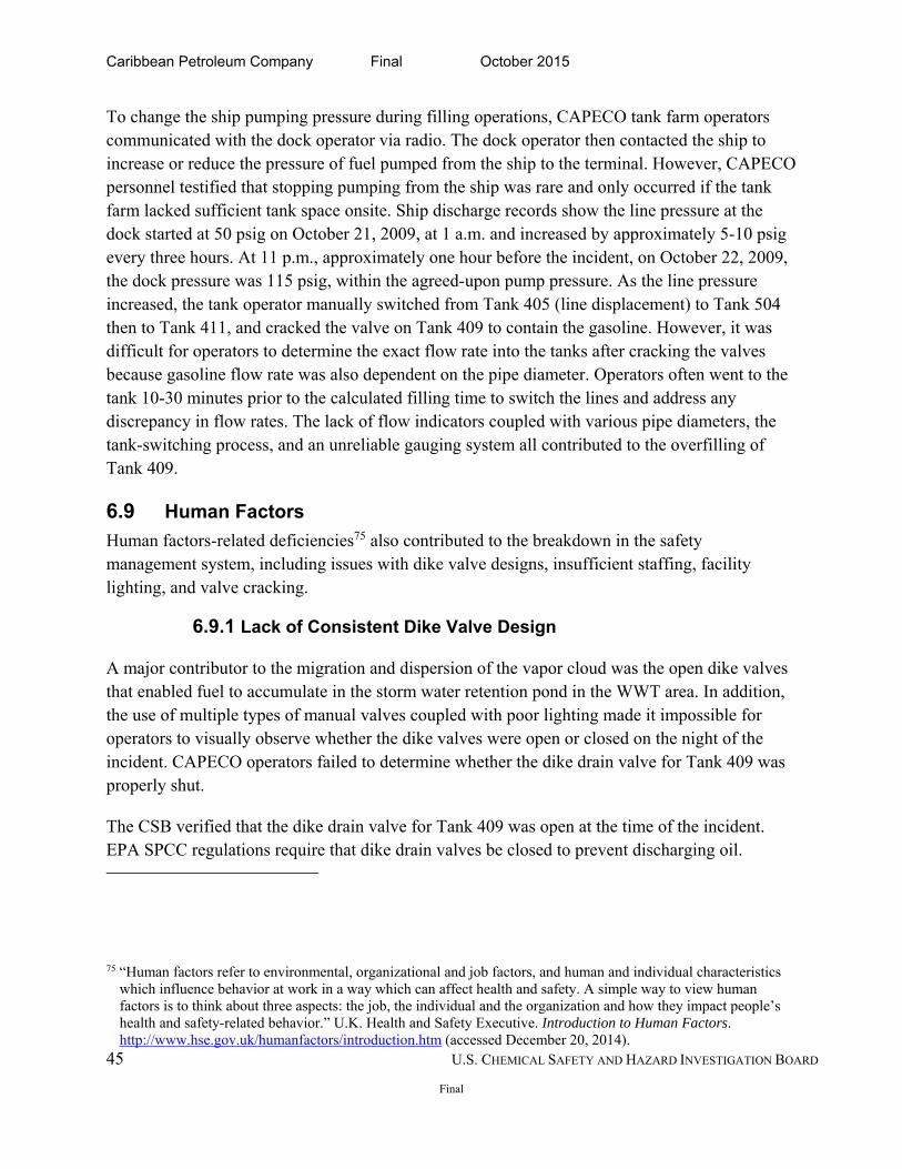
Caribbean Petroleum Company Final October 2015
45 U.S. CHEMICAL SAFETY AND HAZARD INVESTIGATION BOARD
Final
To change the ship pumping pressure during filling operations, CAPECO tank farm operators communicated with the dock operator via radio. The dock operator then contacted the ship to increase or reduce the pressure of fuel pumped from the ship to the terminal. However, CAPECO personnel testified that stopping pumping from the ship was rare and only occurred if the tank farm lacked sufficient tank space onsite. Ship discharge records show the line pressure at the dock started at 50 psig on October 21, 2009, at 1 a.m. and increased by approximately 5-10 psig every three hours. At 11 p.m., approximately one hour before the incident, on October 22, 2009, the dock pressure was 115 psig, within the agreed-upon pump pressure. As the line pressure increased, the tank operator manually switched from Tank 405 (line displacement) to Tank 504 then to Tank 411, and cracked the valve on Tank 409 to contain the gasoline. However, it was difficult for operators to determine the exact flow rate into the tanks after cracking the valves because gasoline flow rate was also dependent on the pipe diameter. Operators often went to the tank 10-30 minutes prior to the calculated filling time to switch the lines and address any discrepancy in flow rates. The lack of flow indicators coupled with various pipe diameters, the tank-switching process, and an unreliable gauging system all contributed to the overfilling of Tank 409.
6.9 Human Factors
Human factors-related deficiencies75 also contributed to the breakdown in the safety management system, including issues with dike valve designs, insufficient staffing, facility lighting, and valve cracking.
6.9.1 Lack of Consistent Dike Valve Design
A major contributor to the migration and dispersion of the vapor cloud was the open dike valves that enabled fuel to accumulate in the storm water retention pond in the WWT area. In addition, the use of multiple types of manual valves coupled with poor lighting made it impossible for operators to visually observe whether the dike valves were open or closed on the night of the incident. CAPECO operators failed to determine whether the dike drain valve for Tank 409 was properly shut.
The CSB verified that the dike drain valve for Tank 409 was open at the time of the incident. EPA SPCC regulations require that dike drain valves be closed to prevent discharging oil.
75 “Human factors refer to environmental, organizational and job factors, and human and individual characteristics which influence behavior at work in a way which can affect health and safety. A simple way to view human factors is to think about three aspects: the job, the individual and the organization and how they impact people’s health and safety-related behavior.” U.K. Health and Safety Executive. Introduction to Human Factors. http://www.hse.gov.uk/humanfactors/introduction.htm (accessed December 20, 2014).
Caribbean Petroleum Company Final October 2015
46 U.S. CHEMICAL SAFETY AND HAZARD INVESTIGATION BOARD
Final
CAPECO’s normal practices required operators to open and close valves during the day shifts. Operators customarily inspected whether the dike drain valves were open or closed from their vehicles as they drove by. The tank farm used both rising stem and fixed stem valves on the dike drains leading to the storm water retention pond in the WWT area. Rising stem valves allowed operators to easily observe the open or closed position while fixed stem valves do not provide a visual indication of the position. The fixed stem valve on the dike drain for Tank 409 made it difficult for tank farm operators to observe its position without physically turning it. (See Figure 15.) In some cases, the valve position could not be determined with a visual inspection because the rising stem valve position was hidden in the sump. (See Figure 15, center photo.) Furthermore, none of the dike valves shown in Figure 15 were consistent with RAGAGEP. Regulatory coverage under the EPA Risk Management Plan (RMP) or OSHA’s Process Safety Management (PSM) Standard requires that CAPECO use the best available engineering practices to assess valve open/close status.
Figure 15: Various dike drain valves at CAPECO. Tank 409 fixed stem dike drain valve (left): position of the valve is undeterminable without physically turning the valve. Rising stem valves (center, right). In some cases, the valve position is hidden in the sump (center).
6.9.2 Lack of Facility Lighting
On the night of the incident, operators could not see the tank overflowing or the vapor cloud forming because the lighting was insufficient. Lighting in the tank farm area was limited; therefore, operators used flashlights to monitor tank farm activity and read liquid levels from the tank side gauges. A 1999 EPA inspection found insufficient lighting at the CAPECO tank farm to “detect spills and prevent vandalism.” Operators used flashlights, which were insufficient to monitor for unusual activity, such as a tank overflowing or a vapor cloud forming. In a 2010
Caribbean Petroleum Company Final October 2015
47 U.S. CHEMICAL SAFETY AND HAZARD INVESTIGATION BOARD
Final
post-incident inspection report, the EPA again noted inadequate facility lighting for discovering unusual activity, such as vandalism and oil discharges in darkness.76
6.9.3 Lack of Sufficient Staffing during Offloading Operations
The management decision to staff each fuel offloading shift with two operators at the tank farm and one operator at the dock provided insufficient staffing resources during filling operations. CAPECO often offloaded inventory into multiple tanks, which required manually switching fuel flow between tanks. This task often required two people due to the increased pressure of the fuel on the valve. Operators addressed this lack of staffing by cracking the valves of the next tank in line to fill. For example, Tank 409 and Tank 411 shared the same line connected to the pipeline. When the operator needed to change the line from the pipeline to fill another tank, he had to call the WWT operator for help, leaving the WWT area unattended.
6.9.4 Valve Cracking
The lack of motor-operated valves compromised the accuracy of tank-filling time estimates. The valves for unloading gasoline were manually operated and as large as 16 to 20 inches. The pressure in the line from the dock was as high as 125 psig, which made opening the valves difficult. To easily change gasoline flow between tanks, operators fully opened the inlet valve to one tank and cracked open the inlet valve on the next tank to be filled. Cracking the inlet valve facilitated opening the valve for the next tank after the previous tank reached the target level. With both valves opened, the flow rate into the individual tanks varied, making it difficult to determine the exact filling time required. Installing motor-operated valves can eliminate the difficulty of manually opening large valves.
6.10 Using a Risk-based Approach to Design an Overfill Prevention System
Bulk petroleum storage and distribution facilities, like CAPECO’s Bayamón facility, are not considered highly hazardous under the U.S. regulatory system, despite often storing flammable liquids near highly populated areas. CAPECO was not required to use a risk-based approach to determine the level of risk posed by facility operations to the nearby community and to mitigate those risks accordingly.
76 General requirements for Spill Prevention, Control, and Countermeasure Plans. Code of Federal Regulations, Part 112, Section 7, Title 40, 2008.
Caribbean Petroleum Company Final October 2015
48 U.S. CHEMICAL SAFETY AND HAZARD INVESTIGATION BOARD
Final
A Safety Instrumented System (SIS)77 approach allows tank terminal operators to design an overfill prevention system for controlling the risk of an overfill incident to various safety integrity levels using multiple layers of protection. Following the promulgation of the US Occupational Health and Safety (OSHA) Process Safety Management (PSM) standard (1910.119), the International Society for Automation (ISA) created ISA 84.01-1996, the Safety Instrumented Systems (SIS) standard. Its intent was to augment the PSM standard for implementing instrumentation and controls necessary for safe operation.78 OSHA recognizes ISA-84 as Recognized and Generally Accepted Good Engineering Practice (RAGAGEP). See Section 8.9 for a discussion of RAGAGEP. Under this standard, a safety system requires robust design and rigorous management to achieve the required integrity.79 In applying SIS for process industries, ISA-84 uses two concepts to reduce the risk of facility-based hazards: a safety lifecycle and safety integrity levels (SIL).80 A safety lifecycle model uses a disciplined systemic approach to design, build, operate, and maintain a facility throughout its lifetime;81 a safety integrity level (SIL) is a probability-of-failure measurement of safety system performance.82 There are four SILs,83 where a higher SIL means that an installed system has a lower potential to fail.
77 SIS is an instrumented system used to implement one or more safety-instrumented functions (SIF). This software implements a safety-instrumented function by programming a single instrumented loop or multiple instrumented loops to a single electronic system. SIS removes the human element from a process when the expected human error rate increases because of automated controls with too many repeated and continuous control changes or when the complexity of work activity increases. A Safety Instrumented Function (SIF) is a safety function associated with a specific safety integrity level that is necessary to achieve functional safety. It can be a safety instrumented protection function or a safety instrumented control function. International Standard IEC 61511-1: Functional safety – Safety instrumented systems.
78 A. Summers. Difference between IEC 8111 and ISA 84.01-1996 (Instrumentation, Systems and Automation
Society, 2003). 79 Buncefield Major Incident Investigation Board. The Buncefield Incident 11 December 2005 Volume 1. 2008.
http://www.buncefieldinvestigation.gov.uk/reports/volume1.pdf. 80 International Society for Automation. Technology ISA-84. http://www.isa-95.com/subpages/technology/isa-
84.php (accessed December 20, 2014). 81 S. Gillespie. Safety Instrumented Systems. http://www.idc-
online.com/technical_references/pdfs/instrumentation/Safety_Instrumented_Systems.pdf (accessed December 20, 2014).
http://www.idc-online.com/technical_references/pdfs/instrumentation/Safety_Instrumented_Systems.pdf 82 Buncefield Major Incident Investigation Board. The Buncefield Incident 11 December 2005 Volume 1 (2008).
http://www.buncefieldinvestigation.gov.uk/reports/volume1.pdf (accessed December 20, 2014). 83 SIL 0 = none is the lowest risk; SIL 1 = 95% of the safety instrumented function (ALARP); SIL 2 =5% SIF; SIL 3
= <1% SIF; SIL 4 =highest risk (nuclear industry) Process Engineering Associates. http://www.processengr.com/ppt_presentations/safety_instrumented_systems.pdf
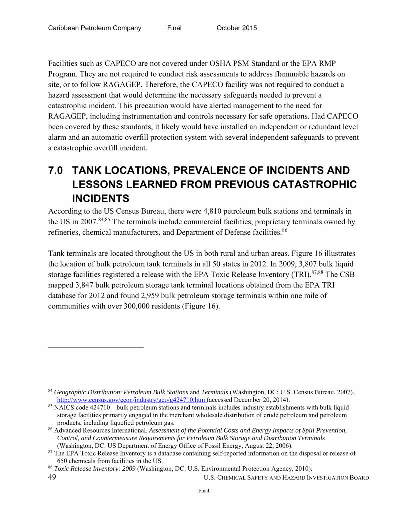
Caribbean Petroleum Company Final October 2015
49 U.S. CHEMICAL SAFETY AND HAZARD INVESTIGATION BOARD
Final
Facilities such as CAPECO are not covered under OSHA PSM Standard or the EPA RMP Program. They are not required to conduct risk assessments to address flammable hazards on site, or to follow RAGAGEP. Therefore, the CAPECO facility was not required to conduct a hazard assessment that would determine the necessary safeguards needed to prevent a catastrophic incident. This precaution would have alerted management to the need for RAGAGEP, including instrumentation and controls necessary for safe operations. Had CAPECO been covered by these standards, it likely would have installed an independent or redundant level alarm and an automatic overfill protection system with several independent safeguards to prevent a catastrophic overfill incident.
7.0 TANK LOCATIONS, PREVALENCE OF INCIDENTS AND LESSONS LEARNED FROM PREVIOUS CATASTROPHIC INCIDENTS
According to the US Census Bureau, there were 4,810 petroleum bulk stations and terminals in the US in 2007.84,85 The terminals include commercial facilities, proprietary terminals owned by refineries, chemical manufacturers, and Department of Defense facilities.86 Tank terminals are located throughout the US in both rural and urban areas. Figure 16 illustrates the location of bulk petroleum tank terminals in all 50 states in 2012. In 2009, 3,807 bulk liquid storage facilities registered a release with the EPA Toxic Release Inventory (TRI).87,88 The CSB mapped 3,847 bulk petroleum storage tank terminal locations obtained from the EPA TRI database for 2012 and found 2,959 bulk petroleum storage terminals within one mile of communities with over 300,000 residents (Figure 16).
84 Geographic Distribution: Petroleum Bulk Stations and Terminals (Washington, DC: U.S. Census Bureau, 2007). http://www.census.gov/econ/industry/geo/g424710.htm (accessed December 20, 2014).
85 NAICS code 424710 – bulk petroleum stations and terminals includes industry establishments with bulk liquid storage facilities primarily engaged in the merchant wholesale distribution of crude petroleum and petroleum products, including liquefied petroleum gas.
86 Advanced Resources International. Assessment of the Potential Costs and Energy Impacts of Spill Prevention, Control, and Countermeasure Requirements for Petroleum Bulk Storage and Distribution Terminals (Washington, DC: US Department of Energy Office of Fossil Energy, August 22, 2006).
87 The EPA Toxic Release Inventory is a database containing self-reported information on the disposal or release of 650 chemicals from facilities in the US.
88 Toxic Release Inventory: 2009 (Washington, DC: U.S. Environmental Protection Agency, 2010).
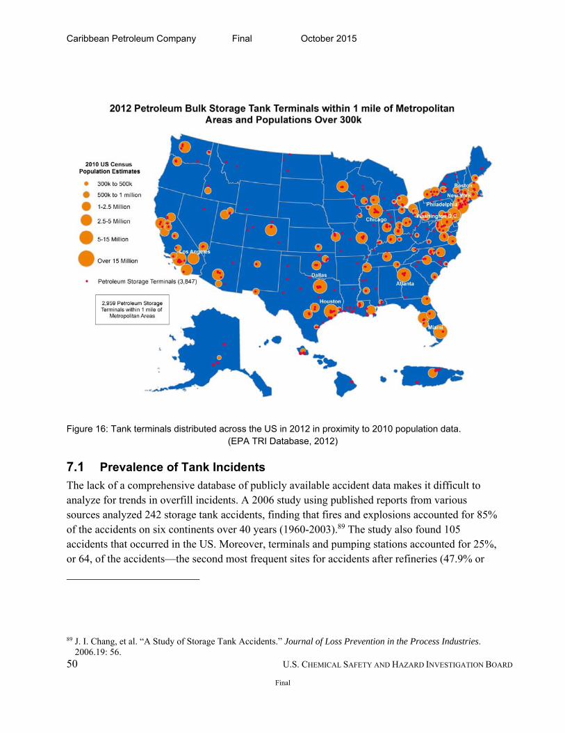
Caribbean Petroleum Company Final October 2015
50 U.S. CHEMICAL SAFETY AND HAZARD INVESTIGATION BOARD
Final
Figure 16: Tank terminals distributed across the US in 2012 in proximity to 2010 population data. (EPA TRI Database, 2012)
7.1 Prevalence of Tank Incidents
The lack of a comprehensive database of publicly available accident data makes it difficult to analyze for trends in overfill incidents. A 2006 study using published reports from various sources analyzed 242 storage tank accidents, finding that fires and explosions accounted for 85% of the accidents on six continents over 40 years (1960-2003).89 The study also found 105 accidents that occurred in the US. Moreover, terminals and pumping stations accounted for 25%, or 64, of the accidents—the second most frequent sites for accidents after refineries (47.9% or
89 J. I. Chang, et al. “A Study of Storage Tank Accidents.” Journal of Loss Prevention in the Process Industries. 2006.19: 56.
Caribbean Petroleum Company Final October 2015
51 U.S. CHEMICAL SAFETY AND HAZARD INVESTIGATION BOARD
Final
116 cases).90 In addition, overfilling was cited as the most frequent cause of an accident during operation; among the 15 overfill incidents found, 87% led to a fire and explosion. Since 2005, three low-frequency, high-consequence incidents involving a vapor cloud formation from a gasoline storage tank resulted in catastrophic explosions and fires. The cost of overflow prevention systems is nominal in contrast with the societal and economic costs of incidents such as Buncefield and CAPECO. A 2006 US Department of Energy Office of Fossil Energy assessment found fully automated liquid level sensing alarms and shutoffs range from $12,000 to $18,000 per tank installation, and liquid level sensing devices with alarms cost $4,000 to $5,000.91
7.2 Lessons Learned from Previous Incidents
Similar overflow incidents have occurred in the US and internationally. The CSB found 22 incidents of overfills and vapor cloud explosions at bulk petroleum tank terminals, 16 of which occurred in the US. The three incidents discussed below and in Appendix B demonstrate the catastrophic potential and high-hazard nature of storing flammable liquids in aboveground storage tanks. Yet US regulations and industry practices do not adequately reflect the lessons learned from such catastrophic incidents and fail to classify terminals storing flammable materials as high-hazard facilities.
7.3 Buncefield (Hertfordshire, UK)
One of the most notable recent incidents—resulting in a number of technical and regulatory recommendations in the United Kingdom—is an explosion and fire that occurred at the Buncefield Oil Storage Depot in Hemel Hempstead, Hertfordshire, UK, on December 11, 2005. Similar to the CAPECO incident, the vapor cloud explosion and multiple tank fires occurred after a tank was overfilled with gasoline. The overfilling tank was equipped with a gauge that allowed operators to monitor filling operations and an independent high-level switch that allowed for automatic shutdown of filling operations if the tank overfilled. But both were inoperable at the time of the incident.92 The explosion generated significant blast pressure,
90 J. I. Chang, et al. “A Study of Storage Tank Accidents.” Journal of Loss Prevention in the Process Industries. 2006.19: 56.
91Advanced Resources International. Assessment of the Potential Costs and Energy Impacts of Spill Prevention, Control, and Countermeasure Requirements for Petroleum Bulk Storage and Distribution Terminals (Washington, DC: U.S. Department of Energy, Office of Fossil Energy, August 22, 2006).
92 The Competent Authority. Control of Major Accident Hazards. Buncefield: Why Did It Happen? (U.K. Health and Safety Executive (HSE) and Environment Agency). http://www.hse.gov.uk/comah/buncefield/buncefield-report.pdf (accessed December 21, 2014).
Caribbean Petroleum Company Final October 2015
52 U.S. CHEMICAL SAFETY AND HAZARD INVESTIGATION BOARD
Final
resulting in additional loss of containment that led to fire and other damage involving 22 tanks. There were no fatalities, but 43 people were injured and the damage to nearby commercial and residential property totaled $1.5 billion.93 The fire burned for four days. Following Buncefield, the UK Health and Safety Executive (HSE) established a Major Incident Investigation Board (MIIB),94 which made recommendations to the industry and regulators concerning the incident. The MIIB recommendations overhauled both the UK legal compliance standards and industry practices governing petroleum storage facilities similar in size to the Buncefield Storage Depot. Differing from the US viewpoint, the United Kingdom considers petroleum storage facilities to be high-hazard facilities, subjecting them to the regulations similar to the US OSHA Process Safety Management (PSM) standard. The UK view allows for additional oversight from the Competent Authority (CA) or the Control of Major Accident Hazards (COMAH). Therefore, covered facilities must demonstrate a major accident prevention policy and a safety management system.95 The MIIB report emphasizes that controlling the risks associated with a major incident like Buncefield requires an integration of safety integrity levels at high-hazard sites, specifically addressing containment of dangerous substances and process safety with mitigation planning against offsite impact, preparedness of emergency response, land use planning for controlling societal risk, and regulatory system enforcement at high-hazard facilities.96 Many of the MIIB recommendations are pertinent to CAPECO. The most salient MIIB recommendations address preventing primary loss of containment,97 conducting a risk assessment, maintaining sector leadership, cultivating a safety culture, and conforming petroleum storage facilities to high-reliability organization principles. Table 2 summarizes and
93 D. M. Johnson, et al. “The Potential for Vapour Cloud Explosions: Lessons from Buncefield.” Journal of Loss Prevention in the Process Industries. (2010.23): 921-927.
94 The Buncefield incident caused the MIIB to conduct a comprehensive review of the design and operation of storage sites, emergency preparedness for and response to incidents, and land use planning. In addition, the MIIB analyzed the regulatory system, including the HSE and UK Environmental Agency requirements governing petroleum storage depots and examined the explosion mechanism of the Buncefield incident. The MIIB produced nine reports published from 2006 to 2009. Follow-up reports resulting from recommendations issued by the MIIB address layer-of-protection analysis while other working groups issued subsequent analysis of the implementation of the HSE recommendations.
95 Buncefield Standards Task Group. 2007. Safety and Environmental Standards for Fuel Storage Sites. http://www.hse.gov.uk/comah/buncefield/bstgfinalreport.pdf. (accessed January 2012) 96 Buncefield Major Incident Investigation Board. 2008. The Buncefield Incident 11 December 2005 Volume 1. http://www.buncefieldinvestigation.gov.uk/reports/volume1.pdf. (accessed January 2012). 97 Primary means of containment are the tanks, pipes, and vessels that hold liquids and the devices fitted to them to allow safe operation. (Buncefield MIIB, 2008).
Caribbean Petroleum Company Final October 2015
53 U.S. CHEMICAL SAFETY AND HAZARD INVESTIGATION BOARD
Final
compares both incidents. Because of the Buncefield incident, the API made changes to the Tank Overfill Prevention Standard (ANSI/API 2350) addressing risk assessment. This report issues additional recommendations to the API to enhance its guidance on conducting a risk assessment. (See Section 8.10.1.)
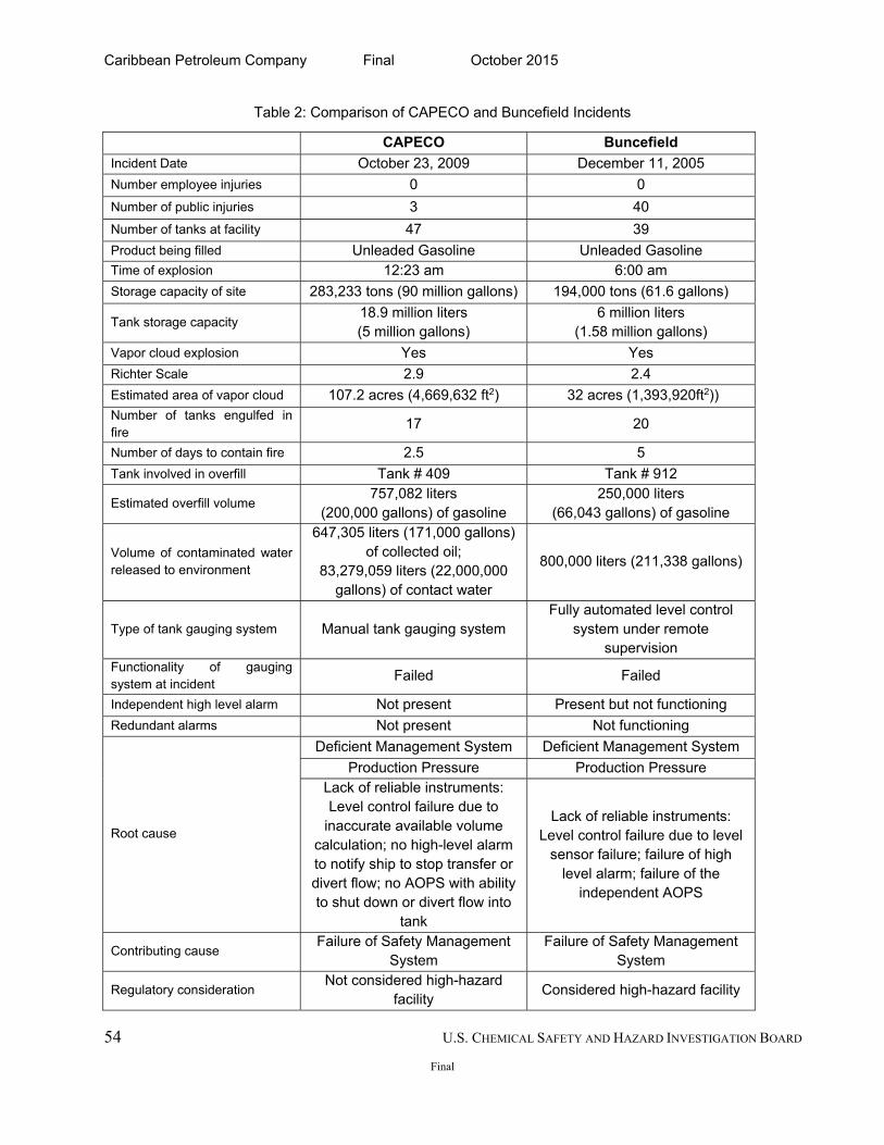
Caribbean Petroleum Company Final October 2015
54 U.S. CHEMICAL SAFETY AND HAZARD INVESTIGATION BOARD
Final
Table 2: Comparison of CAPECO and Buncefield Incidents
CAPECO Buncefield
Incident Date October 23, 2009 December 11, 2005
Number employee injuries 0 0
Number of public injuries 3 40
Number of tanks at facility 47 39
Product being filled Unleaded Gasoline Unleaded Gasoline Time of explosion 12:23 am 6:00 am
Storage capacity of site 283,233 tons (90 million gallons) 194,000 tons (61.6 gallons)
Tank storage capacity 18.9 million liters (5 million gallons)
6 million liters (1.58 million gallons)
Vapor cloud explosion Yes Yes
Richter Scale 2.9 2.4
Estimated area of vapor cloud 107.2 acres (4,669,632 ft2) 32 acres (1,393,920ft2)) Number of tanks engulfed in fire
17 20
Number of days to contain fire 2.5 5
Tank involved in overfill Tank # 409 Tank # 912
Estimated overfill volume 757,082 liters
(200,000 gallons) of gasoline 250,000 liters
(66,043 gallons) of gasoline
Volume of contaminated water released to environment
647,305 liters (171,000 gallons) of collected oil;
83,279,059 liters (22,000,000 gallons) of contact water
800,000 liters (211,338 gallons)
Type of tank gauging system Manual tank gauging system Fully automated level control
system under remote supervision
Functionality of gauging system at incident
Failed Failed
Independent high level alarm Not present Present but not functioning
Redundant alarms Not present Not functioning
Root cause
Deficient Management System Deficient Management System
Production Pressure Production Pressure Lack of reliable instruments: Level control failure due to
inaccurate available volume calculation; no high-level alarm to notify ship to stop transfer or divert flow; no AOPS with ability to shut down or divert flow into
tank
Lack of reliable instruments: Level control failure due to level
sensor failure; failure of high level alarm; failure of the
independent AOPS
Contributing cause Failure of Safety Management
System Failure of Safety Management
System
Regulatory consideration Not considered high-hazard
facility Considered high-hazard facility
Caribbean Petroleum Company Final October 2015
55 U.S. CHEMICAL SAFETY AND HAZARD INVESTIGATION BOARD
Final
7.4 Texaco Oil Company (Newark, NJ)
On January 7, 1983, a similar incident occurred at the Texaco Oil Company tank terminal in Newark, New Jersey. A gasoline vapor cloud exploded when a 1.76-million gallon capacity tank overflowed, resulting in one fatality and 24 injuries. Inadequate monitoring of the rising gasoline levels in the storage tank during filling operations contributed to the overflow, explosion, and subsequent fire. An NFPA report on the incident also attributed the root cause to errors in calculating the available space and pumping rates.98 Equipment damage was observed up to 1,500 feet away from the exploding tank. The overflowing tank had manual level controls. The facility also had no documentation of previous liquid level monitoring in the hours leading up to the explosion. The last “check” on the tank level occurred approximately 24 hours prior to filling operations.99 Following the incident, the Newark Fire Department made recommendations to the NFPA to strengthen its guidance on overfill prevention under the Flammable and Combustible Liquids Code. (See Section 8.10.9.1 for further discussion on NFPA 30.)
7.5 Indian Oil Company (Jaipur, India)
Another recent incident occurred in Jaipur, India, at the Indian Oil Corporation (IOC) Petroleum Oil Lubricants terminal 16 miles south of Jaipur, India. On October 29, 2009, one week after the CAPECO explosion and fire, four operators were transferring gasoline to a tank when the delivery line developed a large leak, which continued unabated for 75 minutes after fumes overcame two operators. The pooling fuel migrated through an open dike drain valve to a storm drain, producing a large vapor cloud. The cloud was ignited by either non-intrinsically safe electrical equipment or a vehicle startup. The resulting explosion and fireball engulfed the entire site. Fire affected 11 tanks and persisted for 11 days. The incident resulted in 11 fatalities, 6 of them IOC employees, and the others from neighboring organizations. Among the 39 recommendations issued, one was for an independent Hazard Operability study (HAZOP) or risk assessment, and another addressing automated operations and improving instrumentation and alarms.100 Appendix B contains a list of other similar incidents.
98 Summary Investigation Report: Gasoline Storage Tank Explosion and Fire. Newark, NJ, 7 January 1983 (Quincy, MA: National Fire Protection Agency, 1983).
99 Summary Investigation Report: Gasoline Storage Tank Explosion and Fire. Newark, NJ, 7 January 1983 (Quincy, MA: National Fire Protection Agency, 1983).
100 T. Fishwick. “The Fire and Explosion at Indian Oil Corporation, Jaipur: A Summary of Events and Outcomes.” Loss Prevention Bulletin (2011. 222): 9.
Caribbean Petroleum Company Final October 2015
56 U.S. CHEMICAL SAFETY AND HAZARD INVESTIGATION BOARD
Final
8.0 REGULATORY ANALYSIS The CSB analysis of the relevant regulatory, industry, and consensus standards for safety and management of bulk petroleum aboveground storage facilities found that the accident at CAPECO might have been prevented had OSHA and EPA considered the facility to pose a high hazard and required the facility to:
1) Conduct a hazard assessment; 2) Implement more than one layer of protection as an independent level alarm system; and 3) Incorporate changes based on lessons learned from previous similar incidents.
The CSB determined that existing regulatory, industry, and consensus standards do not adequately protect workers and the public from the dangers posed by bulk petroleum storage tank terminals. The following section discusses shortcomings of the regulatory, standard and recommended practice framework governing this industry. (See Figure 17.)
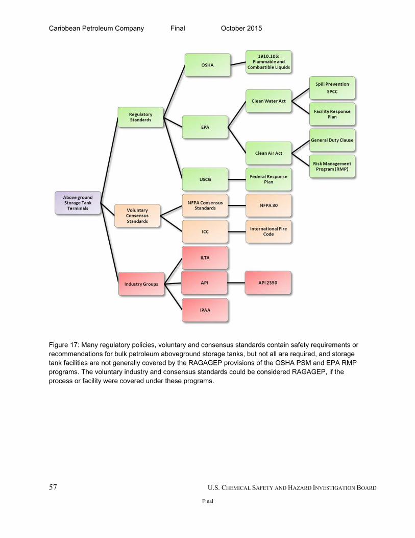
Caribbean Petroleum Company Final October 2015
57 U.S. CHEMICAL SAFETY AND HAZARD INVESTIGATION BOARD
Final
Figure 17: Many regulatory policies, voluntary and consensus standards contain safety requirements or recommendations for bulk petroleum aboveground storage tanks, but not all are required, and storage tank facilities are not generally covered by the RAGAGEP provisions of the OSHA PSM and EPA RMP programs. The voluntary industry and consensus standards could be considered RAGAGEP, if the process or facility were covered under these programs.
Caribbean Petroleum Company Final October 2015
58
8.1 Environmental Protection Agency (EPA)
Although certain environmental statutes and EPA regulations apply to bulk petroleum aboveground storage tank terminals such as CAPECO, the CSB finds these regulations do not adequately protect the public from catastrophic incidents at bulk petroleum storage tank terminals storing NFPA 704, Class 3 flammable liquids:
The EPA Clean Air Act General Duty Clause (CAA Section 112(r)(1)) lacks specific guidance for preventing accidental releases, while other regulations, such as the Risk Management Program (RMP), the Spill Prevention, Control and Countermeasure (SPCC), and the Facility Response Plan (FRP), do not require an overfill prevention program and a robust hazard assessment.
The Clean Air Act (CAA) General Duty Clause protects the public living near facilities. Due to a gasoline exemption and the flammable mixture provision101 under the List Rule (see Section 8.3), bulk petroleum storage tank terminals are not subject to the EPA risk management program regulations because they store NFPA Class 3 flammable liquids not regulated by the standard.
The Clean Water Act (CWA) SPCC regulations, which protect navigable waterways and shorelines from oil spills, require only one layer of protection for overfill prevention and do not require that bulk petroleum tank terminals implement a second layer of protection, such as an independent high level alarm.
8.2 Clean Air Act: The General Duty Clause
Section 112(r)(1) of the CAA, the General Duty Clause, 42 U.S.C. § 7412(r)(1), requires owners and operators of stationary sources102 who produce, store and handle extremely hazardous substances to identify hazards, design, and maintain a safe facility to prevent their release and protect the public.103 The EPA issues chemical safety alerts advising industry on the types of issues covered by the General Duty Clause and publishes alerts on reactive hazards, lightning,
101 Flammable mixtures containing more than 1% of a regulated substance and the overall mixture meets the NFPA 4 flammability criteria are covered and must submit a Risk Management Plan to the EPA. General Duty Clause of the Clean Air Act (Washington, DC: U.S. Environmental Protection Agency, March 2009). http://www.epa.gov/oem/docs/chem/gdc-fact.pdf (accessed December 21, 2014).
102 Stationary source means any buildings, structures, equipment, installations, or substance-emitting stationary activities that belong to the same industrial group, which are located on one or more contiguous properties and under the control of the same person (or persons under common control), and from which an accidental release may occur (63 FR 645).
103 Guidance for Implementation of the General Duty Clause Clean Air Act, Section 112( r )(1) (Washington, DC: U.S. Environmental Protection Agency, Office of Solid Waste and Emergency Response Office of Enforcement and Compliance Assurance, May 2000). http://www2.epa.gov/sites/production/files/2013-10/documents/gdcregionalguidance.pdf (accessed December 21, 2014).
Caribbean Petroleum Company Final October 2015
59
and other catastrophic hazards. In 2009, the EPA issued a Chemical Safety Alert for Rupture Hazard from Liquid Storage Tanks to address catastrophic hazards posed by fertilizer storage tanks.104 However, to date, the EPA has not issued any alerts for overflow hazards from flammable liquids in storage tanks, despite the occurrence of high-consequence incidents such as Texaco Oil Company and Buncefield incidents prior to CAPECO. In addition, the performance-based105 nature of the general duty clause leaves the responsibility of protecting the public up to each covered facility, without any specific requirements from the EPA. The CSB found that further guidance under the General Duty Clause may be necessary to encourage more than one layer of overfill protection for bulk aboveground petroleum storage tank terminals near communities.
8.3 EPA: The List Rule
After a number of chemical accidents in the US and overseas, Congress enacted the Clean Air Act Amendments (CAAA) of 1990. Sections 301 and 112 of the CAAA require that the EPA issue regulations preventing accidental releases that could harm the public.106 Section 112(r) of the CAAA, 42 U.S.C. § 7412 (r), requires owners and operators of stationary sources to identify hazards and to prevent and minimize the effect of accidental releases when extremely hazardous substances are present.107 The EPA promulgated the Risk Management Program rule in 1996 to address accidental releases.108 The CAAA required EPA to promulgate an initial list of 100 substances “known to cause or may [reasonably] be anticipated to cause death, injury, or serious adverse effects to human health or the environment”109 in the event of an accidental release.110
104 Chemical Safety Alert: Rupture Hazard from Liquid Storage Tanks. U.S. Environmental Protection Agency: Washington, DC, September 2009. http://www.epa.gov/osweroe1/docs/chem/tanks7.pdf (accessed December 21, 2014).
105 A performance-based standard, also referred to as a functional approach, allows facilities to define their own methods to achieve the regulatory goal or standard. Examples of performance-based standards are the OSHA PSM standard and a numeric limit on emissions that does not prescribe how it is achieved.
106 CONSAD Research Corporation. Analytical Support and Data Gathering for an Economic Analysis of the Addition of Selected Reactive Chemicals within the Scope of the OSHA Process Safety Management Standard (Washington, DC: U.S. Occupational Safety and Health Administration, 1998).
107 Guidance for the Implementation of the General Duty Clause of the Clean Air Act, Section 112(r)(1). 550-B00-002 (Washington, DC: U.S. Environmental Protection Agency, May 2000): 2.
108 EPA Can Improve Implementation of the Risk Management Program for Airborne Chemical Releases. 09-P-0092 (Washington, DC: U.S. Environmental Protection Agency, February 10, 2009).
109 Guidance for Implementation of the General Duty Clause Clean Air Act, Section 112( r )(1) (Washington, DC: U.S. Environmental Protection Agency, Office of Solid Waste and Emergency Response Office of Enforcement and Compliance Assurance, May 2000). http://www2.epa.gov/sites/production/files/2013-10/documents/gdcregionalguidance.pdf (accessed December 21, 2014).
110 The Public Health and Welfare. U.S. Code, Section 7412(r)(3), Title 42, 2009.
Caribbean Petroleum Company Final October 2015
60
Known as the List Rule, this requirement obliged covered facilities, in addition to other requirements, to submit a Risk Management Plan (RMP) to the EPA when they exceeded the threshold quantity of a regulated substance on the list. The initial list included 77 acutely toxic substances, 63 flammable gases and volatile flammable liquids, and Division 1.1 high-explosive substances as designated by the Department of Transportation (DOT). The List Rule has been amended several times since its promulgation. Shortly after enactment,111 the API and the Institute of Makers of Explosives (IME) filed petitions requesting a judicial review of the List Rule. In settlement of these petitions, the EPA specifically exempted regulated substances in gasoline112 from determining whether a threshold quantity was present in a process.113 The EPA stated, “risks associated with the storage and handling of flammable substances are a function of the properties of the materials, not their end use.”114 The agency argued for “exempting gasoline because it does not meet the NFPA 4 flammability criteria,”115 and “the EPA believes it does not represent a significant threat to the public of vapor cloud explosions.”116 The EPA also exempted flammable mixtures including blendstocks117 and natural gasoline that do not meet the NFPA flammability rating of 4.118 However, flammable mixtures and
111 Petitions were filed within the standard 60-day period under CAA 307(b), around March 1994. The settlement of the petitions occurred in early 1996.
112 Gasoline is exempt from the EPA List Rule because it does not meet the boiling point criterion for listing (NFPA 4 criteria, flammability hazard rating of 4); therefore, this substance is not assigned a threshold level. Approval of Colorado’s Petition To Relax the Federal Gasoline Reid Vapor Pressure Volatility Standard for 1996 and 1997. Federal Register (1996): 61, 73.
113 Regulated Substances for Accidental Release Prevention – Threshold Determination. Code of Federal Regulations, Part 68.115(b)(2)(ii), Title 40, 1998.
114 40 CFR Part 68, List of Regulated Substances and Thresholds for Accidental Release Prevention; Final Rule. Rules and Regulations, January 6, 1998. Federal Register (1998): 63 (3),
115 NFPA 704 defines NFPA 4 flammability criteria to include materials that rapidly or completely vaporize at atmospheric pressure and normal ambient temperature or that are readily dispersed in air and burn readily. This may include flammable gases, flammable cryogenic materials, any liquid or gaseous material that is liquid while under pressure and has a flash point below 22.8°C (73°F) and a boiling point below 37.8°C (100°F) (i.e., Class IA liquids), and materials that ignite spontaneously when exposed to air. Solids containing greater than 0.5 percent by weight of a flammable or combustible solvent are rated by the closed cup flash point of the solvent. NFPA 704. http://www.nfpa.org/codes-and-standards/document-information-pages?mode=code&code=704 (accessed December 21, 2014).
116 40 CFR Part 68 List of Regulated Substances and Thresholds for Accidental Release Prevention; Final Rule. Rules and Regulations, January 6, 1998. Federal Register (1998): 63 (3).
117 Blendstocks are motor gasoline blending components intended for blending with oxygenates to produce finished reformulated motor gasoline. (Energy Information Administration, Definitions, Sources and Explanatory Notes http://www.eia.gov/dnav/pet/tbldefs/pet_move_wkly_tbldef2.asp (accessed December 21, 2014).
118 40 CFR Part 68, List of Regulated Substances and Thresholds for Accidental Release Prevention. Final Rule. Rules and Regulations, 6 January 1998. Federal Register (1998): 63 (3).
Caribbean Petroleum Company Final October 2015
61
blendstocks meeting the NFPA 4 flammability are subject to threshold determinations119 irrespective of their end use. If a mixture consists of 1% or greater concentration of a regulated flammable substance and the mixture meets the NFPA 4 flammability criteria, the EPA considers the entire weight of a flammable mixture as the regulated flammable substance.120 The EPA recognizes specific circumstances in which a facility not covered under the List Rule has the potential for a vapor cloud explosion, and it asserts that the General Duty Clause protects against site-specific factors that “make an unlisted chemical extremely hazardous.”121 The unleaded gasoline involved in the CAPECO incident had an NFPA 704 flammability rating of 3, falling outside the RMP criteria. The flammable mixture also had an API gravity122 of 63.7, characterizing it as highly flammable. Although the components of unleaded gasoline— benzene, toluene, xylene, cyclohexane, trimethyl benzene, and alcohol additives—are not regulated substances under the List Rule, they contribute to its high flammability. In the CAPECO incident, these components resulted in a vapor cloud formation and explosion.123 The magnitude of the CAPECO incident warrants that the EPA reassess its criteria for exempting blendstocks and flammable mixtures that do not meet NFPA 4 flammability criteria. Furthermore, the EPA did not consider the previous incidents when it granted the gasoline and flammable mixture exemption.124 These incidents and the CAPECO explosion demonstrate that a vapor cloud formation from a flammable mixture such as unleaded gasoline can result in catastrophic impact to local communities and workers. In addition, despite a requirement to protect the public under the General Duty Clause, CAPECO did not implement an adequate safety management system to prevent the catastrophic explosion and fire.
119A threshold determination is the method by which a source calculates whether a threshold quantity is present in a process. Exemptions and exclusions of regulated substances from threshold determination allow a source not to include regulated substances in a mixture in specified instances.
120 40 CFR Part 68, List of Regulated Substances and Thresholds for Accidental Release Prevention. Final Rule. Rules and Regulations, January 6, 1998. Federal Register (1998): 63 (3).
121 Ibid. 122 The American Petroleum Institute (API) characterizes flammability of crude oil and condensate by gravity level.
The higher the gravity, the lighter and more flammable the compound; materials below an API gravity value of 35 are characterized as crude oil, while those above 45 are considered condensate.
123 Gasoline with blends that include more than 1% of pentane is subject to coverage under the RMP. 124 See Section 7.2 and Appendix B for incidents excluded from EPA consideration in its gasoline and flammable
mixture exemption.
Caribbean Petroleum Company Final October 2015
62
8.4 Risk Management Program
Under 40 CFR §68, covered facilities fall into three Program Levels (Program 1, 2, or 3) based on a process unit’s potential to affect the public and the requirements to prevent accidents.125 Consistent with OSHA’s PSM requirements, facilities that fall under Program 3 must implement a prevention program that includes process safety information, process hazard analysis, standard operating procedures, training, mechanical integrity, compliance audits, incident investigations, management of change (MOC), pre-startup reviews, employee participation, and hot work permits. Tank terminals similar to CAPECO that store gasoline do not fall under Program 1, 2 or 3 requirements. In addition, under the Risk Management Program, covered facilities are subject to the same recognized and generally accepted good engineering practices (RAGAGEP) requirements for mechanical integrity and process hazard analyses (PHAs) as the OSHA PSM standard.
8.5 Chemical Accident Provisions, Risk Management Plan (RMP)
The EPA’s Chemical Accident Provisions (40 CFR §68) require facilities that have more than a threshold quantity of a List Rule-regulated substance to submit a Risk Management Plan (RMP) identifying the quantity of flammable or toxic material and to report on their accident prevention program, accident history, and planning.126 Every five years, covered facilities must conduct a hazard assessment that considers worst-case scenarios, certify to the EPA their compliance with prevention program requirements,127 and coordinate their emergency response preparedness with local responders. Had CAPECO been required to conduct a hazard assessment that evaluated the quantity of flammable products stored at the terminal and their proximity to the neighboring community, the facility may have had to address the risk of a vapor cloud explosion and resulting multiple tank fires. Under RMP, CAPECO would have had to develop accident prevention programs and coordinate response planning with local emergency responders, actions that might have mitigated the incident. The EPA requested more information from the public and regulated community on amending the RMP rule to include more specific siting requirements as part of the PHA in a July 31, 2014, Request for Information (RFI).128 The CSB issued comments under the RFI encouraging the
125 40 CFR §68.10. Applicability. http://www.law.cornell.edu/cfr/text/40/68.10 (accessed December 21, 2014). 126 Regulated Substances for Accidental Release Prevention. Code of Federal Regulations, Part 68.115(b)(2), Title
40, 1998. 127 Ibid. 128 The RFI was issued under 40 CFR §68, Accidental Release Prevention Requirements: Risk Management
Programs Under the Clean Air Act, Section 112(r)(7).
Caribbean Petroleum Company Final October 2015
63
EPA to provide more guidance on facility siting.129 Examples of siting requirements provided by the EPA include buffer or setback zones for newly covered stationary sources, or establishing safety criteria for siting of structures that house people inside a facility.130
8.6 The Clean Water Act (CWA)
The Federal Water Pollution Act of 1972, or Clean Water Act (CWA), as amended, gives the EPA jurisdiction131 to protect navigable waters from pollution. Section 311 authorizes a program to prevent, prepare for, and respond to discharges of oil and hazardous substances. Section §311(j)(1)(C) provides that the President shall issue regulations establishing procedures, methods, equipment, and other requirements to prevent and contain discharges of oil132 from facilities and vessels, and to contain such discharges. CAPECO was subject to various EPA regulations promulgated under the CWA.
8.6.1 Spill Prevention, Control and Countermeasure (SPCC) Regulations
The Spill Prevention, Control, and Countermeasure (SPCC) requirements govern oil discharge at aboveground storage tank sites. The EPA promulgated the SPCC regulation (40 CFR §112) on January 10, 1974 (See 38 FR 34164). The SPCC regulation requires a facility to prepare and certify by a Professional Engineer, a plan detailing the equipment, workforce, procedures, and steps to prevent and control an oil discharge to navigable waters and shorelines. The regulation at 40 CFR §112.8(c)(8) requires SPCC-subject facilities to provide for overfill protection for each container in accordance with good engineering practice including applicable industry standards.133 The regulation allows the owner/operator of a container to select only one suggested method of overfill controls. The options include, high liquid level alarms at a constantly attended location or surveillance station, high liquid level pump cut off devices to stop
129 Docket No. EPA-HQ-OEM-2014-0328 http://www.csb.gov/assets/1/7/EPA_RFI.pdf. (accessed January 7, 2015) 130 Environmental Protection Agency. 40 CFR Part 68. Accidental Release Prevention Requirement: Risk
Management Programs Under the Clean Air Act, Section 11(r)(7). Proposed Rule. Federal Register. (2014): 79 (147), 44604-44633.
131 CWA jurisdiction includes navigable waters of the United States and adjoining shorelines, the waters of the contiguous zone, and the high seas beyond the contiguous zone in connection with activities under the Outer Continental Shelf Lands Act. It covers activities under the Deepwater Port Act of 1974 or activities that may affect natural resources belonging to, appertaining to, or under the exclusive management authority of the United States, including resources under the Magnuson Fishery Conservation and Management Act of 1976.
132 Under CWA §311(a)(1), “oil” means “oil of any kind or in any form, including, but not limited to, petroleum, fuel oil, sludge, oil refuse, and oil mixed with wastes other than dredged spoil.” Clean Water Act Section 311 – Oil and Hazardous Substances Liability. http://www.epa.gov/region7/public_notices/CWA/section311.htm (accessed December 21, 2014).
133 Environmental Protection Agency. 40 CFR Part 112.8(c)(8). Spill Prevention, Control, and Countermeasure Plan requirements for onshore facilities (excluding production facilities). Section 112.8(c)(8). (2002).
Caribbean Petroleum Company Final October 2015
64
the liquid flow into a tank at a previously established level, direct audible or code signal communication between the container gauger and the pumping station, and a fast response system such as a digital computer, telepulse or direct vision gauges to determine liquid levels in a tank or container. 134 The regulation also requires regular testing of level sensors for the selected overfill prevention option.135
8.6.2 CAPECO’s SPCC History
The CAPECO facility had a history of noncompliance with SPCC regulations. In 1993, EPA inspections noted poor housekeeping, including oil in tank berm areas and inadequate control of vegetation in the secondary containment areas. In 1996, the EPA cited CAPECO for deficiencies in their SPCC plan that include not adequately explaining the engineering controls in place to prevent a spill. The facility also experienced an overfill incident in 1999, when fuel spilled from an asphalt tank outside the tank farm area. Oil flowed out of a vent located at the top of the tank into the secondary containment. Although this incident occurred in a separate process from the tank farm, the EPA findings are relevant to the 2009 overfill incident. The EPA cited the facility for not updating the bulk storage tank installations and for not incorporating fail-safe engineering to prevent the overfill incident.136 After this incident, the EPA recommended that CAPECO consider installing one or more of the following safeguards:
High-level alarms with an audible or visual signal at a constantly manned operation or surveillance station;
High-liquid-level pump cutoff devices set to stop flow at a predetermined tank content level;
Direct audible or code signal communication between the tank gauger and the pumping station; or
A fast response system for determining the liquid of each bulk storage tank, including digital computers, telepulse, or direct vision gauges or their equivalent.
According to EPA records, CAPECO was compliant with recommendations by 2001. The facility installed two levels of protection, the computer system, equipped with a high-liquid level
134 Spill Prevention, Control, and Countermeasure Plan requirements for onshore facilities (excluding production facilities). Code of Federal Regulations, Part 112.8, Title 40 (2002). http://www.ecfr.gov/cgi-bin/text-idx?SID=67da1ecbd5068d7f144a92e0e59ef956&mc=true&node=pt40.22.112&rgn=div5#se40.22.112_18 (accessed June 2015).
135 Ibid. 136 US Environmental Protection Agency Region 2. Review of Revised SPCC Plan for the Caribbean Petroleum
Refining Facility, Bayamón, Puerto Rico (Washington, DC: U.S. Environmental Protection Agency, September 20, 1999).
Caribbean Petroleum Company Final October 2015
65
audible/visual alarm, and established direct communication between the gauger and the pump station, but was not required to conduct a hazard assessment to determine if the two safeguards adequately prevented an overfill. See Section 6.5.1 for discussion on the computer system. After the October 23, 2009, incident, the EPA cited CAPECO again for not having “fail safe engineering”137 on any of its bulk storage tanks at the time of the incident. CAPECO contended that the facility did employ “fail safe engineering,” as evidenced by its gauging system, which included reading the tank side gauge and using the Digital Electric Level Transmitter. The EPA deferred to guidance on fail-safe engineering, referring CAPECO to industry standards. However, the CSB found, both the consensus standards (NFPA 30, Section 8.10.2.1) and industry standard (ANSI/API 2350, Section 8.10.1.1) offer little guidance on fail-safe engineering practices at tank terminals. Furthermore, the 2009 incident breached secondary containment and spilled into navigable waterways. Although the secondary containment captured the gasoline from Tank 409, the open dike valves allowed oil, fire suppression foam, and an oily-water mixture to migrate to the storm water retention pond in the WWT area. The fuel mixture discharged into Las Lajas Creek, which feeds 100 acres of wetlands and nearby Malaria Creek flowing into the Bay of San Juan. (See Section 5.3.1 for a discussion of community impact.) The pooling gasoline in the containment dike also contributed to the formation of the flammable vapor cloud. (See Section 4.3 on flammable vapor cloud development.) The CSB further concludes that a high-level alarm system as part of an automatic overfill prevention system equipped with one additional layer of protection under SPCC could have alerted operators to the high liquid levels, or automatically shut down transfer operations, or diverted the flow operations to another tank. The CSB learned that tank terminal facilities do not have to register or report overfill incidents unless those discharges are in violation of CWA section 311(b)(3), as per 40 CFR §110.6. A 2008 Government Accountability Office (GAO) report found that the EPA did not have a clear understanding of the universe of facilities regulated under SPCC. This limited knowledge hinders the agency’s ability to effectively identify regulated facilities, establish inspection priorities, and evaluate whether the program is achieving its goals.”138 These findings were again reiterated in a 2012 report that found the EPA lacked sufficient data on the facilities covered in the Oil Prevention Program, which includes both the SPCC and Facility Response
137 Fail Safe Engineering refers to the design of a product to fail in a predictable manner, to a “safe state.” P. Herena. The Principle of Fail Safe (American Institute of Chemical Engineers, February 23, 2011). http://chenected.aiche.org/process-safety/the-principle-of-fail-safe/ (accessed December 21, 2014).
138 Government Accountability Office. Aboveground Oil Storage Tanks: More Complete Facility Data Could Improve Implementation of EPA’s Spill Prevention Program, GAO-08-482 (Washington, DC: U.S. Government Accountability Office, April 30, 2008).
Caribbean Petroleum Company Final October 2015
66
Plan (FRP). The 2012 report stated, “the Agency [EPA] remains largely unaware of the identity and compliance status of the vast majority of CWA Section 311 regulated facilities.”139 Furthermore, the 2012 report calls attention to the inadequacy of data collection for OPP-covered facilities: “Agency data systems cannot exchange data with each other, and lack consistent and sufficient codes to categorize deficiencies and noncompliance. These data systems limitations prevent EPA from capturing the full details of a violator’s history and identifying trends in compliance and enforcement.”140 A registry of incidents occurring at tank terminal facilities, such as CAPECO, would allow the EPA to tailor overfill protection requirements more effectively.
8.6.3 Facility Response Plans (FRP)
Section 311(j)(5) of the CWA, amended by the 1990 Oil Pollution Act (OPA), calls for facilities that could cause substantial harm141 from an oil discharge to submit a Facility Response Plan (FRP). The FRP requires contingency measures for oil discharged from an incident.142 Designed in accordance with Sections 112.20, 112.21 and Appendices C-F of the CWA FRP regulation, FRPs demonstrate a facility’s response to a worst-case discharge of oil. Because CAPECO had vessel loading and unloading capabilities, the terminal was also subject to USCG’s FRP regulation at 33 CFR §154. Both the EPA and USCG conducted multiple inspections at the CAPECO facility prior to the incident. The EPA and USCG have separate regulatory jurisdiction for this facility. EPA’s jurisdiction begins at the first valve inside secondary containment whereas the USCG’s jurisdiction begins at this first valve inside secondary containment for the EPA regulated tank and extends to the vessel. The USCG inspects marine operations at the dock and the pipeline carrying fuel to the first valve inside secondary containment. The FRP rule at 40 CFR §112.20(f)(1) outlines the substantial harm criteria that allows for owner/operators to self-identify whether their facilities are subject to the FRP regulation. A facility can be classified for the potential to cause substantial harm if they meet the following
139 Environmental Protection Agency, Office of Inspector General. EPA Needs to Further Improve How It Manages Its Oil Pollution Prevention Program. Report No. 12-P-0253 (Washington, DC: U.S. Environmental Protection Agency, February 6, 2012).
140 Ibid., p.9. 141 A facility could reasonably be expected to cause substantial harm to the environment if it has 42,000 gallons or
more in oil storage capacity and transfers of oil over water to or from vessels, or if it has 1 million gallons or more in oil storage capacity, and if one of the following is true: 1) it has inadequate secondary containment and freeboard; 2) a discharge could cause injury to fish and wildlife and sensitive environments; 3) a discharge could shut down a public drinking water intake; or 4) it has had a reportable oil discharge of 10,000 gallons or more within the last 5 years.
142 Subpart D-Response Requirements: Facility Response Plans, Code of Federal Regulations, Part 112.20, Title 40 (2000).
Caribbean Petroleum Company Final October 2015
67
criteria: 1) The facility transfers oil over water to or from vessels and has a total oil storage capacity greater than or equal to 42,000 gallons; or 2) The facility’s oil storage capacity is greater than or equal to 1 million gallons and one of the following is true:
The facility does not have adequate sized secondary containment for each aboveground storage area;
The facility is located at a distance such that a discharge from the facility could cause injury to fish and wildlife and sensitive environments;143
The facility is located at a distance (i.e., planning distance) such that a discharge from the facility would shut down a public drinking water intake; or
The facility has experienced a reportable oil discharge greater than or equal to 10,000 gallons within the last 5 years.144
In accordance with 40 CFR §112.20(f)(3), all FRPs submitted to EPA are reviewed by EPA to determine whether an oil discharge from the facility could cause significant and substantial harm. Facilities with this harm designation require the EPA approval of their FRP. CAPECO met the substantial harm criteria, had submitted an FRP to EPA Region 2, was designated as a “significant and substantial harm” facility, and was inspected multiple times by EPA inspectors for SPCC and FRP compliance.
8.6.4 EPA FRP Inspection History
Similar to its SPCC record, CAPECO had a history of non-compliance related to FRP requirements. CAPECO submitted its first FRP to the EPA in 1997. However, a 1998 EPA field inspection identified violations, which the facility failed to correct when reapplying for approval in 1999 and 2001. The EPA denied approval of CAPECO’s FRP in 1999 and March 2001.145 CAPECO received approval for its FRP in July 2001; however, another EPA FRP inspection in 2005 revealed deficiencies in maintaining discharge prevention meetings or logs.146
8.6.5 USCG FRP Inspection History
The USCG conducted annual FRP inspections of the CAPECO facility from 2004 to 2011 to evaluate communications, pollution prevention/response, operations/management, firefighting, documentation, and other emergency response elements. However, the FRP inspection failed to
143 This distance is referred to as the “planning distance.” Calculation instructions are outlined in Appendix C of 40 CFR §112.
144 40 CFR §112.20 Facility response plans. (f)(1) 145 Caribbean Petroleum Refining LP. US EPA Region 2 Facility Response Plan (FRP); FRP ID 20027. Caribbean
Petroleum Refining LP: Bayamon, PR (2001). 146Ibid., p.1.
Caribbean Petroleum Company Final October 2015
68
document CAPECO’s ability to fight a catastrophic loss of containment that could result in multiple tank fires. CAPECO received a satisfactory inspection from 2004 to March 2008. Seven months prior to the October explosion and fires CAPECO submitted an updated FRP and received a satisfactory inspection.147
8.6.6 Lack of Robust FRP Inspections
Despite receiving a satisfactory rating on the various components of emergency response, CAPECO experienced the 2009 overfill incident that spilled into nearby wetlands. The CSB found the FRP inspection process does not require FRP inspectors to conduct a thorough evaluation of an emergency response plan that encompasses catastrophic failure of multiple tanks at once. Under the EPA’s jurisdiction, Appendix F of 40 CFR §112.20(h) and Appendix F, Section 1.5.1.2 requires a facility to address chain reactions148 of a tank failure leading to contaminating navigable waters, while the USCG FRP inspection report assesses oil spill preparedness by evaluating a terminal’s pollution prevention and response, firefighting, communications, deck, and cargo, among other factors. However, both FRP inspections lack substantive evaluation of a covered facility’s mitigation efforts to prevent a catastrophic incident like an explosion and multiple tank fires that can contaminate navigable waters. Had the EPA and USCG FRP inspectors been required to fully assess the functioning of the containment dike, dike drain valves, and the full scope of CAPECO’s emergency discharge plan, CAPECO might not have received a satisfactory inspection and would have had to evaluate its inadequate dike drainage system, which led to the spread of the gasoline vapor cloud. See Section 6.9.1 for discussion on dike drain valves.
8.6.7 EPA RMP and SPCC Programs Lack Resources to Inspect Tank Facilities
The CSB has identified significant gaps in the RMP and SPCC programs that warrant the EPA to extend coverage to bulk petroleum terminals storing NFPA 704 Class 3 flammable liquids and above. However, both programs lack the resources to sufficiently inspect all covered facilities. The CSB Chevron investigation report discusses how the EPA’s Risk Management Program lacks the ability to inspect all covered facilities and made recommendations to the Governor of California to “Ensure that a means of sustained funding is established to support an independent,
147United States Coast Guard. Activity Summary Report. Annual Exam, Activity ID 1985003, 2521895, 3093795, 3162359, 3428543 (Washington, DC: U.S. Department of Homeland Security, 2009).
148 A chain reaction of a failure requires a covered facility to consider the impact of the failure on the environment. Facility response training and drills/exercises. Code of Federal Regulations, Part 112.20(h) and Appendix F, Section 1.5.1.2, Title 40 (2000).
Caribbean Petroleum Company Final October 2015
69
well funded, well staffed, technically competent regulator.”149 Federal EPA RMP and SPCC programs lack the capacity to undertake inspection of such tank terminals. A 2009 report of the EPA Risk Management Program found that EPA inspected only 197 of the 493 high-risk facilities identified by the EPA’s Office of Emergency Management. Among the 296 uninspected facilities, 151 had the potential to affect 100,000 people or more in a worst-case accident.150 The report identified a lack of full-time inspectors as one of the main factors limiting the EPA’s ability to conduct on-site audits or inspections of facilities covered under the Risk Management Program. In fiscal year 2009, the EPA had 24 full-time inspectors to cover 11,529 facilities covered in the program.151 For the EPA to sufficiently inspect tank terminals like CAPECO, the Risk Management Program will require additional resources.
8.6.8 The OPP Program Lacks Resources
EPA lacks sufficient staff to inspect all its SPCC- and FRP-covered facilities and lacks a comprehensive understanding of the facilities it regulates. EPA has an estimated 30 to 40 full-time employees to inspect all SPCC- and FRP-covered facilities. From 2008 to 2012, the EPA inspected only 3,700 of the 640,000 facilities covered under SPCC.152 In addition, a 2008 report found “Without more comprehensive data on the universe of facilities that are subject to the SPCC rule, EPA cannot employ a risk-based approach to target its SPCC inspections to those facilities that pose the greatest risks of oil spills into or upon U.S. navigable waters and adjoining shorelines.”153 The same report found that the “incomplete information on the universe of SPCC facilities prevents EPA from determining whether and to what extent the SPCC program is achieving its goals.”154
149 U.S. CSB. Regulatory Report: Chevron Richmond Refinery Pipe Rupture and Fire, Chevron Richmond Refinery #4 Crude Unit, Richmond, CA. August 6, 2012. 2012-03-I-CA (Washington, DC: U.S. Chemical Safety Board, October 2014). http://www.csb.gov/assets/1/19/Chevron_Regulatory_Report_11102014_FINAL_-_post.pdf (accessed December 21, 2014).
150 Environmental Protection Agency. Office of Inspector General. EPA Can Improve Implementation of the Risk Management Program for Airborne Chemical Releases. 09-P-0092 (Washington, DC: U.S. Environmental Protection Agency, February 10, 2009).
151 Ibid. 152 Environmental Protection Agency, Office of Inspector General. EPA Needs to Further Improve How It Manages
Its Oil Pollution Prevention Program. 12-P-0253 (Washington, DC: U.S. Environmental Protection Agency, February 6, 2012).
153 Government Accountability Office, Aboveground Oil Storage Tanks: More Complete Facility Data Could Improve Implementation of EPA’s Spill Prevention Program, GAO-08-482, April 30, 2008.
154 Ibid.
Caribbean Petroleum Company Final October 2015
70
8.7 Occupational Safety and Health Administration (OSHA)
A CSB analysis found deficiencies in various OSHA standards addressing tank terminals in protecting workers from the flammable hazards. In addition, similar to the EPA’s policies, OSHA’s exemption of atmospheric storage tanks from the Process Safety Management (PSM) standard undermines the development of hazard assessments and management of change (MOC) reviews that would have required CAPECO personnel to analyze the hazards posed by terminal operations. Furthermore, specific requirements for robust overfill prevention and risk management are lacking because OSHA regulations do not consider tank terminals as PSM-covered or high-hazard facilities.155
8.7.1 Flammable and Combustible Liquids (1910.106)
OSHA’s Flammable and Combustible Liquids standard (1910.106), which covers tank terminals containing flammable materials, does not require overfill protections for aboveground storage tanks.156 Based on the 1968 version of NFPA 30: Flammable and Combustible Liquids Code, the standard offers no guidance on overfill prevention at terminal facilities during the transfer of flammable or combustible fluids. While recent versions require limited overfill protection, OSHA has not updated 1910.106 to include newer versions of NFPA 30 or other updated good engineering practices. (See Section 8.10.2.1.) The Puerto Rico Occupational Safety and Health Administration (PR OSHA)157 cited CAPECO for endangering the lives of tank farm workers following the incident. Although the October 23, 2009, explosion did not result in any worker injuries, tank farm operators escaped the initial vapor cloud ignition by a few minutes. PR OSHA cited CAPECO under 1910.106, stating:
“At Caribbean Petroleum Refining in Bayamón employees that worked performing routine tasks such as tank operator, waste treatment operator, loading rack operator, among others were exposed or could be exposed to flammable and combustible release, fire and or explosion during the performance of their duties. At the tank farm area the employer stored gasoline, jet fuel, fuel oil and diesel, in above ground tanks, ranging
155 A PSM-covered facility or high-hazard facility, as defined by OSHA PSM, has the potential for a catastrophic release (major uncontrolled emission, fire, or explosion, involving one or more highly hazardous chemicals that present serious danger to employees in the workplace). A facility is defined as the buildings, containers, or equipment which contain a process. Highly hazardous chemical is defined as a substance possessing toxic, reactive, flammable, or explosive properties. Process safety management of highly hazardous chemicals. Code of Federal Regulations, Part 1910.119, Title 29, 2012.
156 1910.106 contains some overfill provisions for tank trucks and tank cars. 157 Puerto Rico OSHA operates as a state plan. Established by the 1975 Occupational Safety and Health Act of
Puerto Rico, the Puerto Rico Occupational Safety and Health Administration (PR OSHA) oversees 29 CFR 1910.106 – Flammable and Combustible Liquids, 29 CFR 1910.119 – Process Safety Management of Highly Hazardous Chemicals, 29 CFR 1910.120 – Hazardous Waste Operations and Emergency Response.
Caribbean Petroleum Company Final October 2015
71
from 500 to 500,000 barrels. The employer did not review the Operational hazard of a large Hydrocarbon release from on-site piping entering the process sewer and storm water sewer systems. Equipment hazards like the additional hazards created by the use of expansion joints on the gasoline transfer lines at the Cummins pump station area. Human factors analysis related to what could occur if operators did not follow instructions for conducting rounds or gauging tanks. Level reading erroneous at the tank gauge and at the operators console. Additional hazards created when operators had to read tank sight gauge levels during the night in low light conditions. Lack of formal written operating procedures for determining the level of storage tanks during filling operations.”
The CSB found OSHA’s Flammable and Combustible Liquids standard to be outdated, concluding that requiring terminal facilities to implement more than one safeguard and good engineering practice would have spared endangering the lives of CAPECO tank farm operators, and they would have likely been notified of the overfill before the vapor cloud developed.
8.7.2 Incorporating Elements of Process Safety Management (PSM) into 1910.106
OSHA’s PSM Standard (29 CFR §1910.119) is a performance-based standard that requires covered entities, such as refineries and chemical plants, to implement a safety management system to prevent accidental releases from highly hazardous processes. PSM requires periodic audits, process hazard analysis (PHA),158 and a management of change (MOC) process. Although the standard needs strengthening,159 these tools indoctrinate additional safety measures into a covered entity’s procedures. OSHA requires employers to use appropriate methods, such as hazard and operability studies (HAZOP), failure mode and effects analyses (FMEA), or fault tree analyses, among other safeguards, to identify and control hazards when conducting a PHA.
158 “The process hazard analysis is a thorough, orderly, systematic approach for identifying, evaluating, and controlling the hazards of processes involving highly hazardous chemicals. The employer must perform an initial process hazard analysis (hazard evaluation) on all processes covered by the [PSM] standard. The process hazard analysis methodology selected must be appropriate to the complexity of the process and must identify, evaluate, and control the hazards involved in the process.” U.S. Department of Labor OSHA. Process Safety Management. OSHA 3132 (Washington, DC: U.S. Department of Labor Occupational Safety and Health Administration, 2000).
159 The CSB made recommendations to amend the PSM regulations in the following investigations: BP Texas City, Motiva, Universal Form Clamp, Chevron and Tesoro. OSHA is undertaking measures to strengthen the standard. The CSB submitted comments to OSHA’s request for information addressing PSM in January 2014. These comments are located on the CSB website: http://www.csb.gov/assets/1/16/CSB_RFIcomments.pdf (accessed December 21, 2014).
Caribbean Petroleum Company Final October 2015
72
This performance-based standard requires the PHA methodology to address factors160 such as engineering and administrative controls and appropriate detection methods, including process monitoring and control instrumentation with alarms.161 Additionally, the standard requires covered facilities to update or revalidate their PHA every five years. PR OSHA adopted the Federal PSM standard as written. The CSB found that the CAPECO incident was attributable to a lack of controls, enforcement, and adherence to these best engineering practices:
(1) A PHA, which might have identified additional engineering controls to prevent the vapor cloud formation.
(2) Engineering controls, such as automatic tank overflow protection system with a separate independent high-level alarm, which could have prevented the overflow.
(3) Facility design and tank spacing in a hazard analysis under aspects of PSM, likely increasing the number of safeguards to prevent an overfill.
Following the shutdown of the CAPECO refinery in 2000, the tank farm facility was no longer covered under PSM due to standard Section (a)(ii)(B) of the PSM standard, which expressly exempts flammable liquid stored in atmospheric storage tanks not connected to a covered process that are below normal boiling point. Under PSM, the facility was required to conduct periodic PHAs and MOCs of its process equipment. Facing fewer regulatory requirements for the tank farm, CAPECO management was not required to maintain the safety management system an MOC, and a periodic hazard assessment mandated under the PSM standard. Any of these requirements might have identified the lack of independent or redundant level alarm, overfill prevention safeguards and poor preventive maintenance. Including elements of PSM like the process hazard methodology into 1910.106 would compel tank terminals storing flammable liquids to reduce the risk posed to the workers and the public.
160 Other PHA factors include the hazards of the process, previous incidents, consequences of failure of engineering and administrative controls, facility siting, human factors, and a qualitative evaluation of possible safety and health effects on employees in the workplace.
161 U.S. Department of Labor OSHA. Process Safety Management. OSHA 3132 (Washington, DC: U.S. Department of Labor Occupational Safety and Health Administration, 2000).
Caribbean Petroleum Company Final October 2015
73
8.8 Puerto Rico Occupational Safety and Health Administration (PR OSHA)
The Puerto Rico Occupational Safety and Health Administration (PR OSHA) visited the CAPECO facility nine times between 1988 and 2000. None of the visits occurred after the refinery shutdown in 2000 when the facility operated solely as a tank farm. In 1988, PR OSHA fined CAPECO for serious violations under the General Duty Clause and the Flammable, Combustible Liquids standard (1910.106) after an employee was fatally injured, and another hospitalized while removing a blind from the pipeline when gasoline spilled and ignited. PR OSHA inspected CAPECO after the October 23, 2009 incident, issuing general duty citations for inadequate overfill prevention consistent with the recommended practice of ANSI/ANSI/API 2350, Recommended Practice, Overfill Protection for Storage Tanks in Petroleum Facilities, and NFPA 30, Flammable and Combustible Liquids Code. Unable to issue citations under the PSM standard due to the atmospheric storage tank exemption, PR OSHA issued multiple serious violations and fines for lacking written procedures and not providing a safe workplace, and it referred to consensus and industry standards to address the flammable hazards onsite. The PHA, MOC, and procedural components of the PSM standard address most of the deficiencies cited by PR OSHA, but CAPECO was not compelled to follow them. If the OSHA PSM standard covered tank terminals, not only would terminals like CAPECO have to conduct a periodic analysis of their hazards, but also PR OSHA would be empowered to issue appropriate citations aimed at preventing similar incidents. The CSB issued a similar recommendation to remove the storage tank exemption in its Motiva investigation.162
8.9 Recognized and Generally Accepted Good Engineering Practices (RAGAGEP)
CFR §1910.119(d)(3)(ii) of the PSM and RMP standards require covered facilities and high-hazard facilities to ensure their equipment complies with recognized and generally accepted good engineering practices (RAGAGEP). These may include the Center for Chemical Process Safety (CCPS) research and publications; ASTM standards; piping, mechanical, and electrical codes; professional society standards; fire codes; and lessons learned from previous incidents.163 OSHA and the EPA can cite facilities covered under PSM and RMP for noncompliance with
162 The CSB Motiva Enterprises LLC investigation called for OSHA to extend PSM coverage to atmospheric storage tanks that could be involved in a catastrophic release interconnected to a covered process with 10,000 pounds of a flammable substance. This recommendation came after one worker was fatally injured and eight were injured when hot work on an aboveground storage tank holding sulfuric acid ignited the flammable vapors inside the tank, releasing contents into the Delaware River on July 17, 2001.
163 A. S. Blair. “RAGAGEP Beyond Regulation: Good Engineering Practices for the Design and Operation of Plants.” Process Safety Progress 26.4: 330–332.
Caribbean Petroleum Company Final October 2015
74
RAGAGEP. Covering tank terminal facilities like CAPECO under PSM and RMP would ensure that they use the best available engineering practices.
8.10 Industry and Consensus Standards
Industry and consensus standards serve as industry best practices and fire codes for tank terminal facilities. In some cases, specific versions of industry standards and fire codes are incorporated by reference into different regulations. The API and the National Fire Protection Association (NFPA) have a number of standards and codes that apply to overfilling a petroleum storage tank.
8.10.1 American Petroleum Institute
The American Petroleum Institute (API), a national trade association representing the oil and natural gas industry, develops voluntary industry standards and recommended practices widely used in industry. Updated periodically, API standards and recommended practices use the term “shall” to communicate requirements and “should” to indicate a recommendations. The American National Standards Institute, ANSI/API Standard 2350 and API Manual of Petroleum Measurement Standards (MPMS) Ch. 3.1A are the most relevant to overfilling of tanks at storage terminals.
8.10.2 ANSI/API Standard 2350 and the Overfill Prevention Process
ANSI/ANSI/API 2350, Overfill Protection for Storage Tanks in Petroleum Facilities, offers guidance on preventing overfills in petroleum storage tanks. The current, fourth edition, released in 2012, recommends that heavier oils including gasoline be included in the scope of a facility-specific overfill prevention program. The standard recognizes that prevention provides the most basic level of protection; thus, while using both the terms “protection” and “prevention,” the document emphasizes prevention. The standard covers minimum overfill (and damage) prevention practices for aboveground storage tanks in petroleum facilities, including refineries, marketing terminals, bulk plants, and pipeline terminals that receive flammable and combustible liquids.
8.10.3 Overfill Prevention Process
To prevent tank overfills, ANSI/API Standard 2350 (2012) calls for implementing an overfill prevention process (OPP) and an automatic overfill prevention system (AOPS) supported by a risk assessment or risk analysis. The standard recommends that an OPP contain a management system, a risk assessment system, defined operational parameters, and other procedures,
Caribbean Petroleum Company Final October 2015
75
including those for receipt termination.164 Incorporating a management system into the overfill prevention process is a significant revision to the standard from previous editions. The standard recommends that facilities implement a safety management system that includes, among other safeguards:
Formal documented operating procedures;
Competent operating personnel;
Scheduled inspections;
A management of change process for personnel and equipment changes; and
Systems for investigating and communicating overfill near misses and lessons learned.
The standard asserts overfill prevention is best achieved through awareness of available tank capacity and inventory, careful monitoring, product movement control, reliable instrumentation and sensors and systems, and automatic overfill prevention systems when recommended by a risk assessment or risk analysis.165 Although this standard did not exist in its current form at the time of the incident, CAPECO lacked formal procedures, sufficient operations personnel, and an effective safety management system.
8.10.4 Inadequate Guidance on Conducting a Risk Assessment
The CAPECO facility was not required to conduct a risk assessment. However, if the facility looked to API for guidance, neither the 2008 nor the current 2012 edition of the ANSI/ANSI/API 2350 standard offers guidance on how to conduct a thorough risk assessment. The risk assessment component of ANSI/ANSI/API 2350 asks the owner and operator of facilities to “categorize risks associated with potential tank overfills as either meeting or not meeting the criteria of the stakeholders.”166 It offers a conceptual framework for conducting an overall risk assessment, without significant details on what is necessary. While this standard provides a level of autonomy to tank terminal owners and operators, it should offer clear guidance on minimum criteria. The standard says tank terminals “shall consider” incorporating regulatory requirements when conducting a risk analysis, but facilities are not limited to using regulatory requirements to define the parameters of their risk analysis. Since the basis for the AOPS is contingent on results from a risk assessment, API should provide more guidance on the risk assessment process or provide authoritative resources for this purpose.
164 Receipt termination refers to stopping or completing tank-filling operations. 165 ANSI/API Standard 2350-2012. Overfill Protection for Storage Tanks in Petroleum Facilities. Fourth edition.
(Washington, DC: American Petroleum Institute, May 2012). 166 Ibid.
Caribbean Petroleum Company Final October 2015
76
8.10.5 Insufficient Requirement for Alarm Levels
Another deficiency of the ANSI/ANSI/API 2350 standard is the levels of concern (LOC) required for necessary level alarms. The standard recommends terminal owners and operators consider a number of parameters167 when establishing LOC for all tanks and at minimum establish three levels: critical-high (CH) levels, high-high level (HH), and maximum-working level (MW).168 ANSI/ANSI/API 2350 recommends using the LOC to set level alarms. The standard also recommends a minimum of three inches separating the CH and HH tank levels to account for potential errors in data and measurement.169 Each level should be set sufficiently below the other to allow appropriate response time to terminate the process if necessary. ANSI/ANSI/API 2350 also stipulates that an AOPS level for emergency action be set below the critical-high level to allow for automatic termination of a receipt before the critical level is reached. The aboveground storage tank industry should implement either a high-level alarm, an automatic overfill prevention system, or both, but the current edition of ANSI/API 2350ANSI/ANSI/API 2350 recommends only a high-level alarm. ANSI/API 2350 neither specifies using a highly reliable alarm nor provides guidance on when a high-level alarm is sufficient to reduce the overfill risk. In the case of CAPECO, the level alarms were prone to failure because the transmitter signal did not transmit the level signal to the computer, forcing operators to work with no automatic fill rate or time to fill estimate. The lack of guidance on when to use high-level alarms may encourage owners and operators of tank terminals to use only one level of alarm when two may be necessary. The UK Government and industry response to Buncefield included comprehensive new guidance on Safety and Environmental Standards for Fuel Storage Sites. Process Safety Leadership Group, Final, (PSLG) report sets minimum standards of overfill protection for gasoline storage tanks.170 The UK Regulator (COMAH Competent
167 ANSI/API 2350 recommends tank terminals consider the product stored, operating practices in the field and for each tank, operating limits for valves and manifolds, tank capacities and physical conditions, the amount of product transferred, delivered or received and the rate of flow into each tank.
168 The critical-high level of concern delineates the highest level that product in the tank can reach without detrimental impacts. The high-high level alarm is set below the critical-high level to enable termination of product receipt before reaching the critical-high level. Maximum-working level is an operational level and the highest product level to fill the tank during normal operations. No alarm is required at this level, but alerts are recommended.
169 ANSI/API Standard 2350-2012: Overfill Protection for Storage Tanks in Petroleum Facilities. Fourth edition (Washington, DC: American Petroleum Institute, May 2012).
170 The Process Safety Leadership Group Report: Safety and Environmental Standards for Fuel Storage Sites, Final Report (Kew, Richmond, UK: U.K. Health and Safety Executive, The Office of Public Sector Information, Information Policy Team, 2009): 25-37. www.hse.gov.uk/comah/buncefield/fuel-storage-sites.pdf (accessed December 21, 2014).
Caribbean Petroleum Company Final October 2015
77
Authority) treats these as the minimum standard to meet UK legal requirements for major hazard sites.
8.10.6 Categories
ANSI/API 2350 also establishes the level of overfill protection based on three categories of onsite or remote monitoring:
Category 1 includes fully attended and continuously monitored storage facilities, which have the option to install level instrumentation. Operations staff may terminate receipt of product if emergencies arise.
Category 2 includes semi-attended facilities and requires personnel to be present during the start of receipt and transfer operations and to attend the operations for 30 minutes. This category requires a storage facility to have an automatic tank gauging system with an independent high-level alarm transmitted to a local or remote control center.
Category 3 is for unattended facilities. It requires both an automatic tank gauging system and an independent high-level alarm.
Overall, these categories are arbitrary—API does not explain its rationale—despite increasing layers of protection with each category. CAPECO, for example, was a fully attended facility that would have fallen under Category 1. Because the level instrument did not function appropriately, operators were unable to terminate receipt because they were unable to recognize they had an overfill developing. Had CAPECO been required to use a functioning independent high-level alarm and automatic overfill prevention system, surpassing the Category 3 requirements, notification of the overflow would have sounded, and automatic termination of the transfer would have occurred prior to the tank overfill. Additionally, ANSI/API 2350 does not discuss the risk reduction achieved in each of these categories compared to an automatic overfill prevention system. It also does not consider that increased flow rates or flammability of various products may require more layers of protection. At CAPECO, the tank farm stored unleaded gasoline (NFPA flammability 3), jet fuel (NFPA Flammability 2), diesel fuel (NFPA flammability 2), and fuel oil (NFPA flammability 2), all with different NFPA ratings requiring varying layers of protection. The current ANSI/API 2350 does not go far enough to require implementing an automatic overflow prevention system for all tank terminals but acknowledges it may be necessary based on risk level. It leaves the decision to the owner/operator of the facility. Finally, the standard
Caribbean Petroleum Company Final October 2015
78
does not provide sufficient guidance to facilities on how to fully assess their hazards and make decisions based on the best overfill prevention plan. To further streamline the hazard assessment process and facilitate safety audits on new or existing tank farms, ANSI/API 2350 should provide guidance on creating a risk-based system to assign all tanks a risk level.
8.10.7 Lack of One Industry Standard for Operations at Tank Farms
The CSB found that while multiple standard practices govern tank farm operations, a single industry standard for tank terminal operations does not exist, including for filling operations. For example, to avert hydrocarbon ignition in the petroleum industry, API 2003, “Protection against Ignitions Arising out of Static, Lightning, and Stay Currents” (2008), provides best practices for preventing static and stray electrical currents.171 While the standard provides charts that compare pipe diameter, flow velocities, and flow rates that minimize static and stray currents, it is not specific to tank filling operations. Similarly, API MPMS, Chapter 3.1A, Standard Practice for the Manual Gauging of Petroleum and Petroleum Products, 3rd edition (August 2013), discussed in Section 6.5, offers useful information on manual gauging and floating roof displacement, but it is unlikely that the standard practice is accessible to the aboveground tank industry. Furthermore, in addition to ANSI/ANSI/API 2350, these standard practices are not mandatory but considered RAGAGEP under PSM and RMP. Creating one standard practice, or publicizing the existence of all standard and recommended practices governing aboveground storage tank operations including references to international standards172 and best practices at tank terminals, would enable facilities to readily access these good engineering practices.
8.10.8 International Fire Code (IFC)
The International Code Council (ICC) is a consensus organization that develops the International Fire Code (IFC) in addition to other I-Codes. I-Codes are “minimum safeguards for people at
171 ANSI/API Standard API 2003-2008. Protection against Ignitions Arising out of Static, Lightning, and Stay Currents. Seventh edition (Washington, DC: American Petroleum Institute, January 2008), 172 The UK Government response to Buncefield published guidance on 'Identification of Instrumental level detection
systems used with Buncefield in-scope substances. Health and Safety Laboratory. Identification of Instrumented Level Detection and Measurement Systems Used with
Buncefield In-scope Substances (Buxton, Derbyshire, UK: U.K. Health and Safety Executive, 2011). www.hse.gov.uk/research/rrpdf/rr872.pdf (accessed December 21, 2014).
Caribbean Petroleum Company Final October 2015
79
home, at school and in the workplace.” 173 The I-Codes are building safety and fire prevention codes. Puerto Rico adopted the International Fire Code (IFC); therefore, all municipalities on the island are required to follow the IFC guidance to prevent fires. At the time of the incident, the 2009 edition of IFC was in place. The 2009 IFC Section 3404.2.7.5.8, “Overfill Prevention,” requires the use of an overfill prevention system for each tank over 1,320 gallons of flammable liquids falling within Class I, II and IIIA.174 Same as the NFPA, the IFC defines gasoline as a class 1B liquid. Similar to the NFPA recommendations and the SPCC requirements for filling operations, the IFC requires that in no case should the tank fill in excess of 95% of its capacity. IFC provides two options to achieve this requirement:
1. Install an audible or visual alarm system that signals the tank has reached 90% of the capacity, and automatically shut off flow after a tank reaches 95% of its capacity.
2. Reduce the flow rate to not more than 15 gallons per minute (0.95 L/sec) in the system so that at the reduced flow rate, the tank will not overfill for 30 minutes and automatically shut off flow into the tank so that none of the fittings on the top of the tank are exposed to product because of overfilling.175
Although CAPECO had audible alarms that were not functioning, they were not required to have an independent audible or visual alarm to indicate rising liquid levels in Tank 409. The ICC modified the overfill prevention text above in the 2015 edition IFC by requiring terminal owners and operators to provide an independent means of notifying the person filling the tank that the fluid level has reached 90% of tank capacity. The code then provides options that include an audible or visual alarm signal, a level gauge marked at 90% of tank capacity or other approved means. The CSB recognizes the ICC for requiring the independent level notification in addition to automatic shutdown as one viable option to prevent an overfill incident. However, the ICC did not go far enough to require:
1) A visual or audible alarm physically separate and independent from the level control and monitoring system;
2) A hazard assessment to determine the necessary safeguards and operations, as well as the reliability of the gauging system and operator monitoring, to prevent an overfill, especially for terminals near a community or sensitive environment, or
173 International Code Council. http://www.iccsafe.org/AboutICC/Pages/default.aspx (accessed December 21, 2014). 174 ICC defines flammable liquids as a liquid having a closed cup flash point below 100ºF (38ºC). Class 1 liquids
include Class 1A liquids having a flash point below 73ºF (23ºC) and a boiling point below 100ºF (38ºC); Class IB liquids having a flash point below 73ºF (23ºC) and a boiling point at or above 100ºF (38ºC); and Class IC liquids having a flash point at or above 73F (23ºC) and below 100F (38ºC).
175 International Fire Code 2009. http://publicecodes.cyberregs.com/icod/ifc/2009/ (accessed December 21, 2014).
Caribbean Petroleum Company Final October 2015
80
3) Proof testing to ensure the overfill prevention system is tested regularly. Including these safety parameters into the IFC and extending it to both existing and new tank terminals will further ensure an incident like CAPECO does not occur.
8.10.9 National Fire Protection Association (NFPA)
The NFPA, a nonprofit organization, develops consensus codes and standards for fire protection and prevention. The standards are voluntary but can be adopted by reference into law. Various groups, including insurance companies, engineers, and safety professionals, use the codes and standards. Approximately 250 panels and committees within the NFPA develop and revise NFPA codes and standards. Although Puerto Rico adopted the International Fire Code (IFC) issued by the International Code Council (ICC), many states have adopted NFPA codes. NFPA 30, Flammable and Combustible Liquids Code (2003), had overfill provisions that applied to tank terminals like CAPECO at the time of the 2009 incident.
8.10.9.1 NFPA 30: Code for Storage of Flammable and Combustible Liquids
NFPA 30 provides guidance on storing and transporting flammable and combustible liquids from mainline pipelines and marine vessels. The NFPA defines flammable liquids having an NFPA 704 flammability rating of 3 as class 1B liquids.176 Section 21.7.1 of the NFPA 30 code, “Prevention of Overfilling of Storage Tanks,” addresses overfill hazards for tanks containing flammable liquids, such as those at CAPECO, but lists an automatic overfill prevention system as only one of three options. The code also references ANSI/API 2350, Overfill Protection for Storage Tanks in Petroleum Facilities, for additional guidance. The 2008, 2012, and 2015 editions of NFPA 30 require terminal facilities storing gasoline to follow formal written procedures or to provide equipment or both to prevent overfilling of tanks by choosing one of the following options:
176 NFPA 30 defines flammable liquids as any liquid that has a closed-cup flash point below 100ºF (37.8ºC). Flammable liquids are further classified into Class I, II, and III liquids. Class I liquids include Class IA, which is any liquid with a flash point below 73ºF (22.8ºC) and a boiling point below 100ºF (37.8ºC); Class IB, which is any liquid with a flash point below 73ºF (22.8ºC) and a boiling point of or above 100ºF (37.8Cº); and Class IC, which is any liquid with a flash point at or above 73ºF (22.8ºC), but below 100ºF (37.8ºC). Class II and Class III liquids are considered combustible liquids because they have a flash point at or above 100ºF (37.8ºC) and at or above 140ºF (93ºC). NFPA 30: Flammable and Combustible Liquids Code (Quincy, MA: National Fire Protection Association, 2014). http://www.nfpa.org/codes-and-standards/document-information-pages?mode=code&code=30 (accessed December 21, 2014).
Caribbean Petroleum Company Final October 2015
81
1) Gauge tanks at intervals in accordance with established procedures by deploying personnel continuously on the premises during product receipt. Maintain communication with the supplier so flow can be shut down or diverted in accordance with established procedures.
2) Equip tanks with a high-level detection device that is either independent of any gauging equipment or incorporates a gauging and alarm system with electronic self-checking to indicate when the gauging and alarm system has failed. Locate alarms where on-duty personnel throughout product transfer can arrange for flow stoppage or diversion in accordance with established procedures.
3) Equip tanks with an independent high-level detection system that will automatically shut down or divert flow in accordance with established procedures.
CAPECO was fully compliant with the NFPA 30 since the facility implemented option 1, but it had neither a high-level alarm nor an automatic overfill prevention system that allowed for automatic shutdown. The only overfill protection was the hourly gauging performed as part of the level control and monitoring system. This was insufficient given the fill rate of Tank 409. The NFPA first amended the overfill prevention guidance in 1981 to require overfill prevention for tanks located near a residence or community.177 Then after the Texaco Tank Farm incident in Newark, New Jersey, occurred during the 1984 revision cycle (see Section 7.4 and Appendix B), the Newark Fire Department issued a comment, asking the NFPA 30 committee to require:
1) Gauging tanks at frequent intervals during transfer of product; 2) Increasing communication with pipeline or marine personnel; 3) Equipping terminals with the ability to rapidly shut down or divert flow; and 4) Installing independent high-level alarms that automatically shut down or divert flow
during filling operations.
The NFPA 30 committee amended the standard to require one of the four recommendations,178 stating, “It would be inappropriate and unjustifiably burdensome to require cumulative provisions.” The technical committee of NFPA 30 stated that any one of the methods would
177 R. Benedetti. Flammable and Combustible Liquids Code Handbook. Third edition (Quincy, MA: National Fire Protection Association, 1987).
178 In 1984, the NFPA 30 committee required overfill protection whenever Class 1 liquids were transferred from mainline pipelines or marine vessels, formal written procedures, a continuous presence of personnel during the transfer operation at manned facilities, and two-way communication with the supply source. The committee also required a high-level detection device independent of any gauging equipment and allowed alternatives to the three options if approved by the local authority with jurisdiction.
Caribbean Petroleum Company Final October 2015
82
provide an acceptable degree of safety.179 It asserted that one of the four options would also protect unmanned, fully automated receiving terminals that have a good safety record. These remote terminals would have been required to implement all four level control recommendations, had the Newark Fire Department recommendations been adopted by the NFPA 30 committee.180 The four options taken together improve the reliability of the level control and monitoring system and ensure that an automatic overfill prevention system is used to detect and prevent an overflow incident. Recent findings from Buncefield and now CAPECO further enhance the need for more robust overfill prevention guidance beyond one of the four options presented by the NFPA 30 committee in 1984. The CSB finds it necessary to further strengthen the overfill protection language in NFPA 30 to require all four options within an automatic overfill prevention system. In addition, a hazard assessment should be completed considering a facility’s proximity to neighboring communities and sensitive environments, the complexity of terminal operations, the reliability of tank gauging system and operator monitoring, and periodic proof testing.181 This assessment should ensure 1) the overfill system continues to function appropriately and 2) a facility implements and maintains an overfill prevention system that addresses the site-specific hazards. These requirements should extend to both old and new tanks. The OSHA Flammable and Combustible Liquids standard (1910.106), incorporates by reference the 1968 version of NFPA 30. (See Section 8.7.1.) However, the current 2015 version of NFPA 30 does not require an automatic overfill prevention system and an independent high-level alarm or automatic shutdown to prevent a similar incident like CAPECO from occurring—despite prior recommendations to do so following the Texaco Oil Company tank overfill incident in 1983 discussed in Section 7.4.
179 R. Benedetti. Flammable and Combustible Liquids Code Handbook. Third edition. (Quincy, MA: National Fire Protection Association, 1987).
180 Ibid. 181 ANSI/ANSI/API 2350 defines proof testing as a complete overfill prevention system instrumentation loop test
through the primary sensing element verifying appropriate response all the way from sensors to the final control element including alarms. The standard identifies proof testing as an essential element in maintaining the reliability of overfill prevention systems. Section 4.5.5.4 of the ANSI/ANSI/API 2350 standard recommends the testing procedures be in sequential format to ensure safe, consistent practices and the testing procedures be accessible to personnel responsible for testing, inspection, and maintenance of the overfill prevention system. American Petroleum Institute. ANSI/API Standard 2350-2012. Overfill Protection for Storage Tanks in Petroleum Facilities. Fourth edition (Washington, DC: American Petroleum Institute, May 2012).
Caribbean Petroleum Company Final October 2015
83
To prevent another overfill incident like CAPECO’s, OSHA should incorporate the most updated version of NFPA 30 with the CSB recommendation to incorporate more than one safeguard.
8.11 Trade Associations
Both the International Liquid Terminals Association (ILTA) and the Independent Petroleum Association of America (IPAA) represent small independent producers and storage terminals in the US. They can advocate for safer operations at their member facilities by endorsing and publicizing best industry practices.
9.0 ROOT AND SYSTEMIC CAUSES The CSB’s investigation identified the following key findings: Physical Cause
1) During an operation to transfer gasoline from the vessel Cape Bruny tanker ship, gasoline overflowed from CAPECO Tank 409, resulting in a vapor cloud formation encompassing approximately 107 acres of the CAPECO tank farm.
2) The gasoline vapor cloud migrated to low-lying areas of the tank farm and to the storm water retention pond in the wastewater treatment (WWT) area through open dike valves.
3) The vapor cloud ignited in the WWT area, which was not electrically classified for use in a flammable atmosphere.
4) Multiple proximate causes likely contributed to Tank 409 overfill:
Malfunctioning tank side gauge during filling operations that led to inaccurate tank levels being recorded;
Normal variations in the gasoline flow rate and pressure from the Cape Bruny without the facility’s ability to identify and incorporate the flow rate change in real time into tank fill time calculations may have contributed to the overfill;
Potential failure of the tank’s internal floating roof due to turbulence and other factors may have contributed to the overfill.
Control Failures 1) An unreliable level control and monitoring system did not provide accurate and timely
information for the operator to prevent overfilling Tank 409. 2) The failure-prone float and tape gauges and the unreliable level transmitters proved
ineffectual. The level transmitters were frequently out of service due to lightning damage. 3) Insufficient independent and separate safeguards to prevent overfill, such as a high-level
alarm and an automatic overfill prevention system (AOPS) compromised facility safety. Safety Management Systems
1) Inadequate formal tank filling procedures were restricted to a list of equipment to be manipulated. In addition, the outdated procedures were often applicable to the tank farm when the refinery was in operation.
Caribbean Petroleum Company Final October 2015
84
2) The automatic tank gauging system, the only level control and monitoring system to support the operator in preventing overfill, was often out of service.
3) The defective level transmitter was not sending data for Tank 409 or 107 to the computer in the operator shack or to the supervisor’s office on the day of the incident.
4) A nonexistent automatic overfill prevention system and the inability to rapidly stop transfer operations or divert flow before an overfill weakened CAPECO’s safety program.
5) Ill-equipped CAPECO tanks were left with an unreliable level monitoring and control system or a high-level alarm system.
Safety Management Systems 1) Tanks were not equipped with an independent high-level alarm system. 2) Tanks were not equipped with an independent Automatic Overfill Prevention System
(AOPS) for terminating transfer operations.
Human Factors 1) The design of the dike valve system made it difficult to distinguish between open and
closed valve positions 2) Insufficient lighting in the tank farm areas hindered operators from observing the
overfilling of Tank 409 and the subsequent vapor cloud formation.
Lack of Reporting Requirements
1) The CSB analysis of the EPA’s Toxic Release Inventory data for 2012 found that 2,959 bulk petroleum tank terminals are within one mile of communities with over 300,000 residents.
2) An incomplete national incident database for assessing the frequency of specific types of incidents at bulk petroleum storage tank terminals inhibits the development and implementation of more tailored regulatory requirements, industry consensus standards, and best practices in this sector.
Emergency Response Findings
1) CAPECO and the local fire department lacked sufficient firefighting equipment to effectively fight and control a fire involving multiple tanks because they are not required to conduct a risk analysis where they have to consider and plan for the potential of a vapor cloud explosion involving multiple tanks.
2) CAPECO did not preplan with local emergency responders or adequately train facility personnel to deal with a fire involving multiple tanks.
3) Local fire departments lacked sufficient training and resources to respond to industrial fires and explosion.
4) There was a lack of coordination among the 43 federal, commonwealth and nongovernmental organizations that responded to the CAPECO incident.
Caribbean Petroleum Company Final October 2015
85
Regulatory Findings
1) The US regulatory system does not consider bulk aboveground storage tank terminals storing flammable liquid to be highly hazardous, even those near communities. Although the EPA characterizes facilities like CAPECO as substantial harm facilities, under the Facility Response Plan requirements, the risk assessment required for these facilities do not consider the potential of multiple tank releases as a worst case scenario.
2) Due to a lack of regulatory coverage under the Occupational Safety and Health Administration’s (OSHA) Process Safety Management (PSM) standard and the Environmental Protection Agency’s (EPA) Risk Management Plan (RMP), tank terminal facilities are not required to conduct risk assessments to address flammable hazards on site or to follow Recognized and Generally Accepted Good Engineering Practices (RAGAGEP).
3) A high-level alarm system or high-integrity overfill prevention system are not required by OSHA’s Flammable and Combustible Liquids standard, the EPA’s Spill Prevention Control and Countermeasure (SPCC) requirements. While facilities covered under SPCC must certify an SPCC plan by a Professional Engineer, only the EPA FRP plans meeting the substantial harm criteria are approved by the EPA. Furthermore, under SPCC facilities similar to CAPECO do not have to report overfill incidents unless oil is discharged to navigable waters.
Industry Standards
1) Despite past incidents in the US and internationally, the response of US industry, trade associations, professional associations, and standard-setting organizations has been inadequate to prevent similar incidents in the US.
2) NFPA 30 only requires one layer of protection on storage tanks, at minimum consistent gauging without requirement for an independent or redundant level alarm or an automatic overfill prevention system.
3) ANSI/API 2350 only requires an automatic overfill prevention system for remotely operated facilities and does not offer substantial guidance on conducting a risk assessment that considers the complexity of site operations, the type of flammable and combustible liquids stored at the facility or proximity to nearby communities when considering the necessary safeguards to protect the public. In addition, there is a lack of one comprehensive industry standard to address tank terminal operations, including tank-filling operations and overfill prevention.
4) ICC does not require an independent audible or visual alarm to indicate rising liquid levels.
Caribbean Petroleum Company Final October 2015
86
10.0 RECOMMENDATIONS
Environmental Protection Agency (EPA)
2010-02-PR R1 Revise where necessary the Spill Prevention, Control and Countermeasure (SPCC); Facility Response Plan (FRP); and/or Accidental Release Prevention Program (40 CFR Part 68) rules to prevent impacts to the environment and/or public from spills, releases, fires, and explosions that can occur at bulk aboveground storage facilities storing gasoline, jet fuels, blendstocks, and other flammable liquids having an NFPA 704 flammability rating of 3 or higher.
At a minimum, these revisions shall incorporate the following provisions: a) Ensure bulk above ground storage facilities conduct and document a risk assessment that
takes into account the following factors: 1. The existence of nearby populations and sensitive environments; 2. The nature and intensity of facility operations; 3. Realistic reliability of the tank gauging system; and
4. The extent/rigor of operator monitoring b) Equip bulk aboveground storage containers/tanks with automatic overfill prevention systems
that are physically separate and independent from the tank level control systems. c) Ensure these automatic overfill prevention systems follow good engineering practices. d) Engineer, operate, and maintain automatic overfill prevention systems to achieve appropriate
safety integrity levels in accordance with good engineering practices, such as Part 1 of International Electro-technical Commission (IEC) 61511-SER ed1.0B-2004, Functional Safety – Safety Instrumented Systems for the Process Industry Sector.
e) Regularly inspect and test automatic overfill prevention systems to ensure their proper operation in accordance with good engineering practice.
2010-02-PR R2 Conduct a survey of randomly selected bulk aboveground storage containers storing gasoline or other NFPA 704 flammability rating of 3 or higher at terminals in high risk locations (such as near population centers or sensitive environments) that are already subject to the Spill Prevention, Control and Countermeasure (SPCC) and/or Facility Response Plan (FRP) rules to determine:
a) The nature of the safety management systems in place to prevent overfilling a storage tank during loading operations. Analysis of the safety management systems should include equipment, training, staffing, operating procedures and preventative maintenance programs.
b) The extent to which terminals use independent high level alarms, automated shutoff/diversion systems, redundant level alarms or other technical means to prevent overfilling a tank
Caribbean Petroleum Company Final October 2015
87
c) The history of overfilling incidents at the facilities, with or without consequence d) Whether additional reporting requirements are needed to understand the types of
incidents leading to overfilling spills that breach secondary containment and have the potential to impact the environment and/or the public, as well as the number of safeguards needed to prevent them.
2010-02-PR R3
As an interim measure, until the rule changes in CSB Recommendation No. 2010-02-I-PR-R1are adopted and go into effect: issue appropriate guidance or an alert, similar to EPA’s previously issued Chemical Safety Alert addressing Rupture Hazard from Liquid Storage Tanks, to illustrate the hazards posed by spills, releases, fires and explosions due to overfilling bulk aboveground storage containers storing gasoline, jet fuel, blendstocks, and other flammable liquids having an NFPA 704 flammability rating of 3 or higher.
Occupational Safety and Health Administration (OSHA) 2010-02-PR R4
a) Revise the Flammable and Combustible Liquids standard (29 CFR§ 1910.106) to require installing, using, and maintaining a high-integrity automatic overfill prevention system with a means of level detection, logic/control equipment, and independent means of flow control for bulk aboveground storage tanks containing gasoline, jet fuel, other fuel mixtures or blendstocks, and other flammable liquids having an NFPA 704 flammability rating of 3 or higher, to protect against loss of containment. At a minimum, this system shall meet the following requirements:
1. Separated physically and electronically and independent from the tank gauging system.
2. Engineered, operated, and maintained to achieve an appropriate level of safety integrity in accordance with the requirements of Part 1 of International Electrotechnical Commission (IEC) 61511-SER ed1.0B-2004, Functional Safety – Safety Instrumented Systems for the Process Industry Sector. Such a system would employ a safety integrity level (SIL) documented in accordance with the principles in Part 3 of IEC 61511-SER ed1.0B-2004, accounting for the following factors:
i. The existence of nearby populations and sensitive environments; ii. The nature and intensity of facility operations;
iii. Realistic reliability for the tank gauging system; and iv. The extent/rigor of operator monitoring.
3. Proof tested in accordance with the validated arrangements and procedures with sufficient frequency to ensure the specified safety integrity level is maintained.
b) Establish hazard analysis, management of change and mechanical integrity management system elements for bulk above ground storage tanks in the revised 1910.106 standard
Caribbean Petroleum Company Final October 2015
88
that are similar to those in the Process Safety Management of Highly Hazardous Chemicals standard (29 CFR §1910.119) and ensure these facilities are subject to Recognized and Generally Accepted Good Engineering Practices (RAGAGEP).
International Code Council (ICC) 2010-02-PR R5 Revise the Section 5704.2.7.5.8 (2015), Overfill Prevention of the International Fire Code (IFC) to require an automatic overfill prevention system (AOPS) for bulk aboveground storage tank terminals storing gasoline, jet fuel, other fuel mixtures or blendstocks, and other flammable liquids having an NFPA 704 flammability rating of 3 or higher, or equivalent designation. These safeguards shall meet the following requirements:
a) Engineered, operated, and maintained to achieve an appropriate safety integrity level in accordance with the requirements of Part 1 of International Electrotechnical Commission (IEC) 61511-SER ed1-2004, Functional Safety – Safety Instrumented Systems for the Process Industry Sector.
b) Specified to achieve the necessary risk reduction as determined by a documented risk assessment methodology in accordance with Center for Chemical Process Safety Guidelines for Hazard Evaluation Procedures, 3rd Edition, accounting for the following factors:
i. The existence of nearby populations and sensitive environments; ii. The nature and intensity of facility operations;
iii. Realistic reliability for the tank gauging system; and iv. The extent/rigor of operator monitoring.
c) Proof tested in accordance with the validated arrangements and procedures with sufficient frequency to maintain the specified safety integrity level.
d) Ensure that the above changes are not subject to grandfathering provisions in the codes.
National Fire Protection Association (NFPA) 2010-02-PR R6 Revise NFPA 30, Flammable and Combustible Liquids Code, Section 21.7.1.1 (2015) for bulk aboveground storage tank terminals storing gasoline, jet fuel, other fuel mixtures or blendstocks, and other flammable liquids having an NFPA 704 flammability rating of 3 or greater. This modification shall meet the following requirements:
a) More than one safeguard to prevent a tank overfill, all within an automatic overfill prevention system as described in ANSI/API Standard 2350 (2015) Overfill Protection for Storage Tanks in Petroleum Facilities with an independent level alarm as one of the safeguards. The safeguards should meet the following standards:
1. Separated physically and electronically and independent from the tank gauging system;
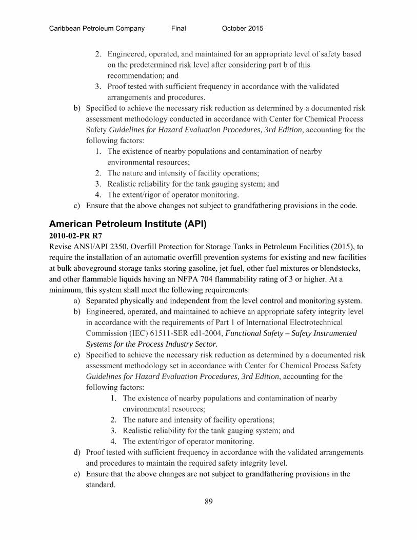
Caribbean Petroleum Company Final October 2015
89
2. Engineered, operated, and maintained for an appropriate level of safety based on the predetermined risk level after considering part b of this recommendation; and
3. Proof tested with sufficient frequency in accordance with the validated arrangements and procedures.
b) Specified to achieve the necessary risk reduction as determined by a documented risk assessment methodology conducted in accordance with Center for Chemical Process Safety Guidelines for Hazard Evaluation Procedures, 3rd Edition, accounting for the following factors:
1. The existence of nearby populations and contamination of nearby environmental resources;
2. The nature and intensity of facility operations; 3. Realistic reliability for the tank gauging system; and 4. The extent/rigor of operator monitoring.
c) Ensure that the above changes not subject to grandfathering provisions in the code.
American Petroleum Institute (API) 2010-02-PR R7 Revise ANSI/API 2350, Overfill Protection for Storage Tanks in Petroleum Facilities (2015), to require the installation of an automatic overfill prevention systems for existing and new facilities at bulk aboveground storage tanks storing gasoline, jet fuel, other fuel mixtures or blendstocks, and other flammable liquids having an NFPA 704 flammability rating of 3 or higher. At a minimum, this system shall meet the following requirements:
a) Separated physically and independent from the level control and monitoring system. b) Engineered, operated, and maintained to achieve an appropriate safety integrity level
in accordance with the requirements of Part 1 of International Electrotechnical Commission (IEC) 61511-SER ed1-2004, Functional Safety – Safety Instrumented Systems for the Process Industry Sector.
c) Specified to achieve the necessary risk reduction as determined by a documented risk assessment methodology set in accordance with Center for Chemical Process Safety Guidelines for Hazard Evaluation Procedures, 3rd Edition, accounting for the following factors:
1. The existence of nearby populations and contamination of nearby environmental resources;
2. The nature and intensity of facility operations; 3. Realistic reliability for the tank gauging system; and 4. The extent/rigor of operator monitoring.
d) Proof tested with sufficient frequency in accordance with the validated arrangements and procedures to maintain the required safety integrity level.
e) Ensure that the above changes are not subject to grandfathering provisions in the standard.
Caribbean Petroleum Company Final October 2015
90
2010-02-PR R8 Develop detailed guidance on conducting a risk assessment for onsite and offsite impacts of a potential tank overfill during transfer operations involving one and multiple tanks and for determining the Safety Integrity Level of the required overfill prevention safeguard to replace Annex E of ANSI/API 2350, Overfill Protection for Storage Tanks in Petroleum Facilities (2015). 2010-02-PR R9 Develop a single publication or resource describing all API standards and other relevant codes, standards, guidance, and information for filling operations of aboveground storage tanks in petroleum facilities that describes:
a) The required design and management practices for control of filling operations; b) The minimum set of independent overfill prevention safeguards if the control fails;
and c) Operational challenges (e.g., monitoring/calculating flow rates, ability to maintain
constant line pressures, and influences of valve cracking) related to loading multiple tanks concurrently from a single product source.
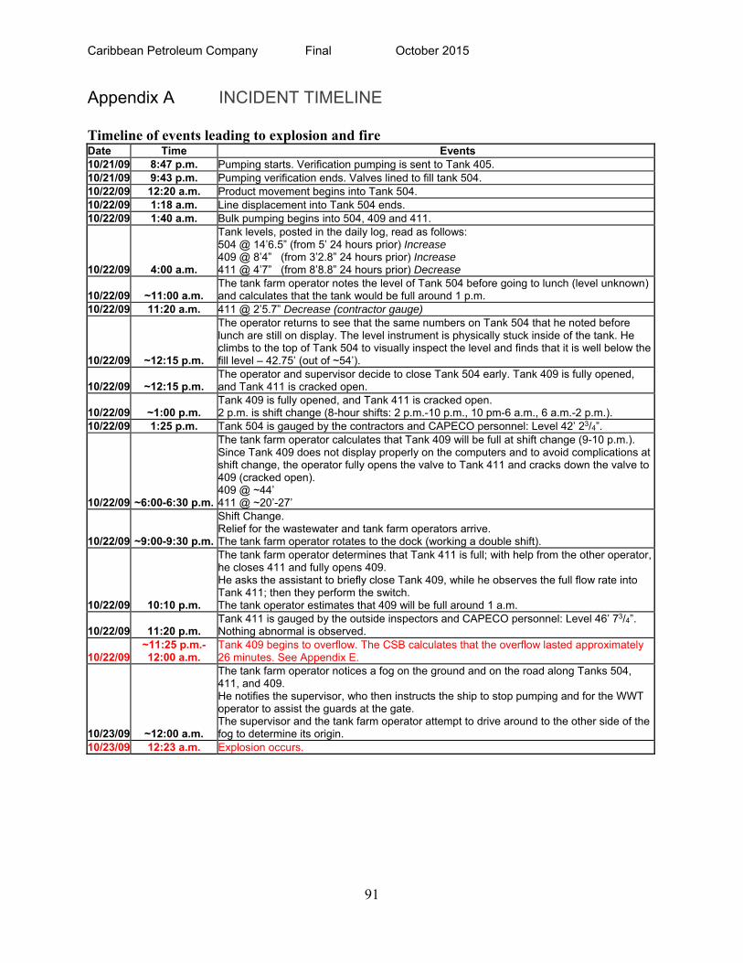
Caribbean Petroleum Company Final October 2015
91
Appendix A INCIDENT TIMELINE
Timeline of events leading to explosion and fire Date Time Events10/21/09 8:47 p.m. Pumping starts. Verification pumping is sent to Tank 405. 10/21/09 9:43 p.m. Pumping verification ends. Valves lined to fill tank 504. 10/22/09 12:20 a.m. Product movement begins into Tank 504. 10/22/09 1:18 a.m. Line displacement into Tank 504 ends. 10/22/09 1:40 a.m. Bulk pumping begins into 504, 409 and 411.
10/22/09 4:00 a.m.
Tank levels, posted in the daily log, read as follows: 504 @ 14’6.5” (from 5’ 24 hours prior) Increase 409 @ 8’4” (from 3’2.8” 24 hours prior) Increase 411 @ 4’7” (from 8’8.8” 24 hours prior) Decrease
10/22/09 ~11:00 a.m. The tank farm operator notes the level of Tank 504 before going to lunch (level unknown) and calculates that the tank would be full around 1 p.m.
10/22/09 11:20 a.m. 411 @ 2’5.7” Decrease (contractor gauge)
10/22/09 ~12:15 p.m.
The operator returns to see that the same numbers on Tank 504 that he noted before lunch are still on display. The level instrument is physically stuck inside of the tank. He climbs to the top of Tank 504 to visually inspect the level and finds that it is well below the fill level – 42.75’ (out of ~54’).
10/22/09 ~12:15 p.m. The operator and supervisor decide to close Tank 504 early. Tank 409 is fully opened, and Tank 411 is cracked open.
10/22/09 ~1:00 p.m. Tank 409 is fully opened, and Tank 411 is cracked open. 2 p.m. is shift change (8-hour shifts: 2 p.m.-10 p.m., 10 pm-6 a.m., 6 a.m.-2 p.m.).
10/22/09 1:25 p.m. Tank 504 is gauged by the contractors and CAPECO personnel: Level 42’ 23/4”.
10/22/09 ~6:00-6:30 p.m.
The tank farm operator calculates that Tank 409 will be full at shift change (9-10 p.m.). Since Tank 409 does not display properly on the computers and to avoid complications at shift change, the operator fully opens the valve to Tank 411 and cracks down the valve to 409 (cracked open). 409 @ ~44’ 411 @ ~20’-27’
10/22/09 ~9:00-9:30 p.m.
Shift Change. Relief for the wastewater and tank farm operators arrive. The tank farm operator rotates to the dock (working a double shift).
10/22/09 10:10 p.m.
The tank farm operator determines that Tank 411 is full; with help from the other operator,he closes 411 and fully opens 409. He asks the assistant to briefly close Tank 409, while he observes the full flow rate into Tank 411; then they perform the switch. The tank operator estimates that 409 will be full around 1 a.m.
10/22/09 11:20 p.m. Tank 411 is gauged by the outside inspectors and CAPECO personnel: Level 46’ 73/4”. Nothing abnormal is observed.
10/22/09 ~11:25 p.m.-12:00 a.m.
Tank 409 begins to overflow. The CSB calculates that the overflow lasted approximately 26 minutes. See Appendix E.
10/23/09 ~12:00 a.m.
The tank farm operator notices a fog on the ground and on the road along Tanks 504, 411, and 409. He notifies the supervisor, who then instructs the ship to stop pumping and for the WWT operator to assist the guards at the gate. The supervisor and the tank farm operator attempt to drive around to the other side of the fog to determine its origin.
10/23/09 12:23 a.m. Explosion occurs.
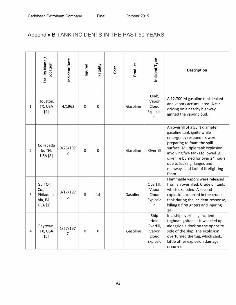
Caribbean Petroleum Company Final October 2015
92
Appendix B TANK INCIDENTS IN THE PAST 50 YEARS
Facility Nam
e /
Location
Incident Date
Injured
Fatality
Cost
Product
Incident Type
Description
1 Houston, TX, USA
[4] 4/1962 0 0 Gasoline
Leak, Vapor Cloud Explosio
n
A 12,700 M gasoline tank leaked and vapors accumulated. A car driving on a nearby highway ignited the vapor cloud.
2 Collegedale, TN, USA [8]
9/25/1972
0 0 Gasoline Overfill
An overfill of a 55 ft diameter gasoline tank ignite while emergency responders were preparing to foam the spill surface. Multiple tank explosion involving five tanks followed. A dike fire burned for over 24 hours due to leaking flanges and manways and lack of firefighting foam.
3
Gulf Oil Co., Philadelphia, PA, USA [1]
8/17/1975
8 14 Gasoline
Overfill, Vapor Cloud Explosio
n
Flammable vapors were released from an overfilled. Crude oil tank, which exploded. A second explosion occurred in the crude tank during the incident response, killing 8 firefighters and injuring 14.
4 Baytown, TX, USA
[5]
1/27/1977
0 0 Gasoline
Ship Hold
Overfill, Vapor Cloud Explosio
n
In a ship overfilling incident, a tugboat ignited as it was tied up alongside a dock on the opposite side of the ship. The explosion overturned the tug, which sank. Little other explosion damage occurred.
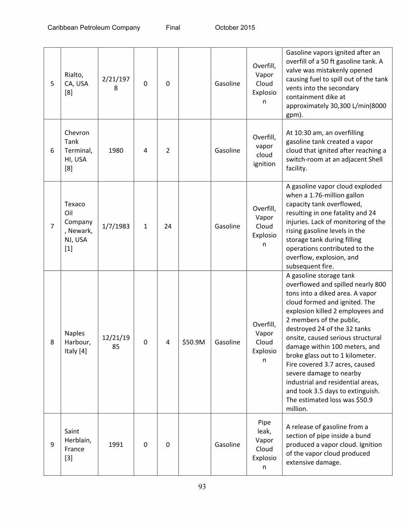
Caribbean Petroleum Company Final October 2015
93
5 Rialto, CA, USA [8]
2/21/1978
0 0 Gasoline
Overfill, Vapor Cloud Explosio
n
Gasoline vapors ignited after an overfill of a 50 ft gasoline tank. A valve was mistakenly opened causing fuel to spill out of the tank vents into the secondary containment dike at approximately 30,300 L/min(8000 gpm).
6
Chevron Tank Terminal, HI, USA [8]
1980 4 2 Gasoline
Overfill, vapor cloud ignition
At 10:30 am, an overfilling gasoline tank created a vapor cloud that ignited after reaching a switch‐room at an adjacent Shell facility.
7
Texaco Oil Company, Newark, NJ, USA [1]
1/7/1983 1 24 Gasoline
Overfill, Vapor Cloud Explosio
n
A gasoline vapor cloud exploded when a 1.76‐million gallon capacity tank overflowed, resulting in one fatality and 24 injuries. Lack of monitoring of the rising gasoline levels in the storage tank during filling operations contributed to the overflow, explosion, and subsequent fire.
8 Naples Harbour, Italy [4]
12/21/1985
0 4 $50.9M Gasoline
Overfill, Vapor Cloud Explosio
n
A gasoline storage tank overflowed and spilled nearly 800 tons into a diked area. A vapor cloud formed and ignited. The explosion killed 2 employees and 2 members of the public, destroyed 24 of the 32 tanks onsite, caused serious structural damage within 100 meters, and broke glass out to 1 kilometer. Fire covered 3.7 acres, caused severe damage to nearby industrial and residential areas, and took 3.5 days to extinguish. The estimated loss was $50.9 million.
9
Saint Herblain, France [3]
1991 0 0 Gasoline
Pipe leak, Vapor Cloud Explosio
n
A release of gasoline from a section of pipe inside a bund produced a vapor cloud. Ignition of the vapor cloud produced extensive damage.
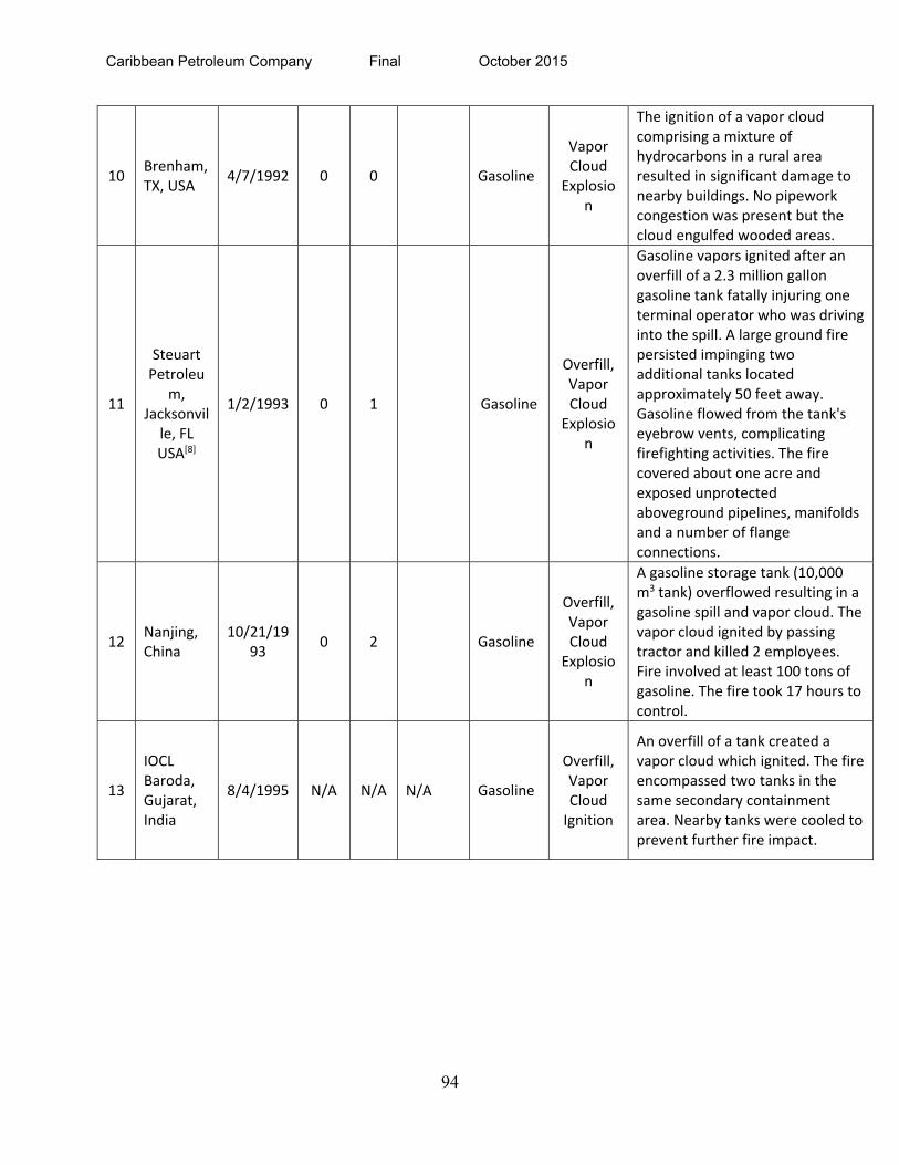
Caribbean Petroleum Company Final October 2015
94
10 Brenham, TX, USA
4/7/1992 0 0 Gasoline
Vapor Cloud Explosio
n
The ignition of a vapor cloud comprising a mixture of hydrocarbons in a rural area resulted in significant damage to nearby buildings. No pipework congestion was present but the cloud engulfed wooded areas.
11
Steuart Petroleu
m, Jacksonville, FL USA[8]
1/2/1993 0 1 Gasoline
Overfill, Vapor Cloud Explosio
n
Gasoline vapors ignited after an overfill of a 2.3 million gallon gasoline tank fatally injuring one terminal operator who was driving into the spill. A large ground fire persisted impinging two additional tanks located approximately 50 feet away. Gasoline flowed from the tank's eyebrow vents, complicating firefighting activities. The fire covered about one acre and exposed unprotected aboveground pipelines, manifolds and a number of flange connections.
12 Nanjing, China
10/21/1993
0 2 Gasoline
Overfill, Vapor Cloud Explosio
n
A gasoline storage tank (10,000 m3 tank) overflowed resulting in a gasoline spill and vapor cloud. The vapor cloud ignited by passing tractor and killed 2 employees. Fire involved at least 100 tons of gasoline. The fire took 17 hours to control.
13
IOCL Baroda, Gujarat, India
8/4/1995 N/A N/A N/A Gasoline
Overfill, Vapor Cloud Ignition
An overfill of a tank created a vapor cloud which ignited. The fire encompassed two tanks in the same secondary containment area. Nearby tanks were cooled to prevent further fire impact.
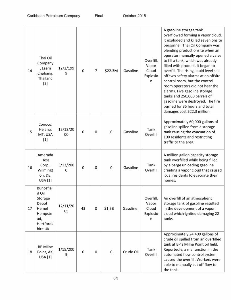
Caribbean Petroleum Company Final October 2015
95
14
Thai Oil Company, Laem
Chabang, Thailand
[2]
12/2/1999
0 7 $22.3M Gasoline
Overfill, Vapor Cloud Explosio
n
A gasoline storage tank overflowed forming a vapor cloud. It exploded and killed seven onsite personnel. Thai Oil Company was blending product onsite when an operator manually opened a valve to fill a tank, which was already filled with product. It began to overfill. The rising liquid level set off two safety alarms at an offsite control room, but the control room operators did not hear the alarms. Five gasoline storage tanks and 250,000 barrels of gasoline were destroyed. The fire burned for 35 hours and total damages cost $22.3 million.
15
Conoco, Helana, MT, USA
[1]
12/13/2000
0 0 0 Gasoline Tank
Overfill
Approximately 60,000 gallons of gasoline spilled from a storage tank causing the evacuation of 100 residents and restricting traffic to the area.
16
Amerada Hess Corp.,
Wilmington, DE, USA [1]
3/13/2000
0 0 0 Gasoline Tank
Overfill
A million gallon capacity storage tank overfilled while being filled by a barge unloading gasoline creating a vapor cloud that caused local residents to evacuate their homes.
17
Buncefield Oil Storage Depot Hemel Hempstead, Hertfordshire UK
12/11/2005
43 0 $1.5B Gasoline
Overfill, Vapor Cloud Explosio
n
An overfill of an atmospheric storage tank of gasoline resulted in the development of a vapor cloud which ignited damaging 22 tanks.
18 BP Milne Point, AK, USA [1]
1/15/2009
0 0 0 Crude Oil Tank
Overfill
Approximately 24,400 gallons of crude oil spilled from an overfilled tank at BP's Milne Point oil field. Reportedly, a malfunction in the automated flow control system caused the overfill. Workers were able to manually cut off flow to the tank.
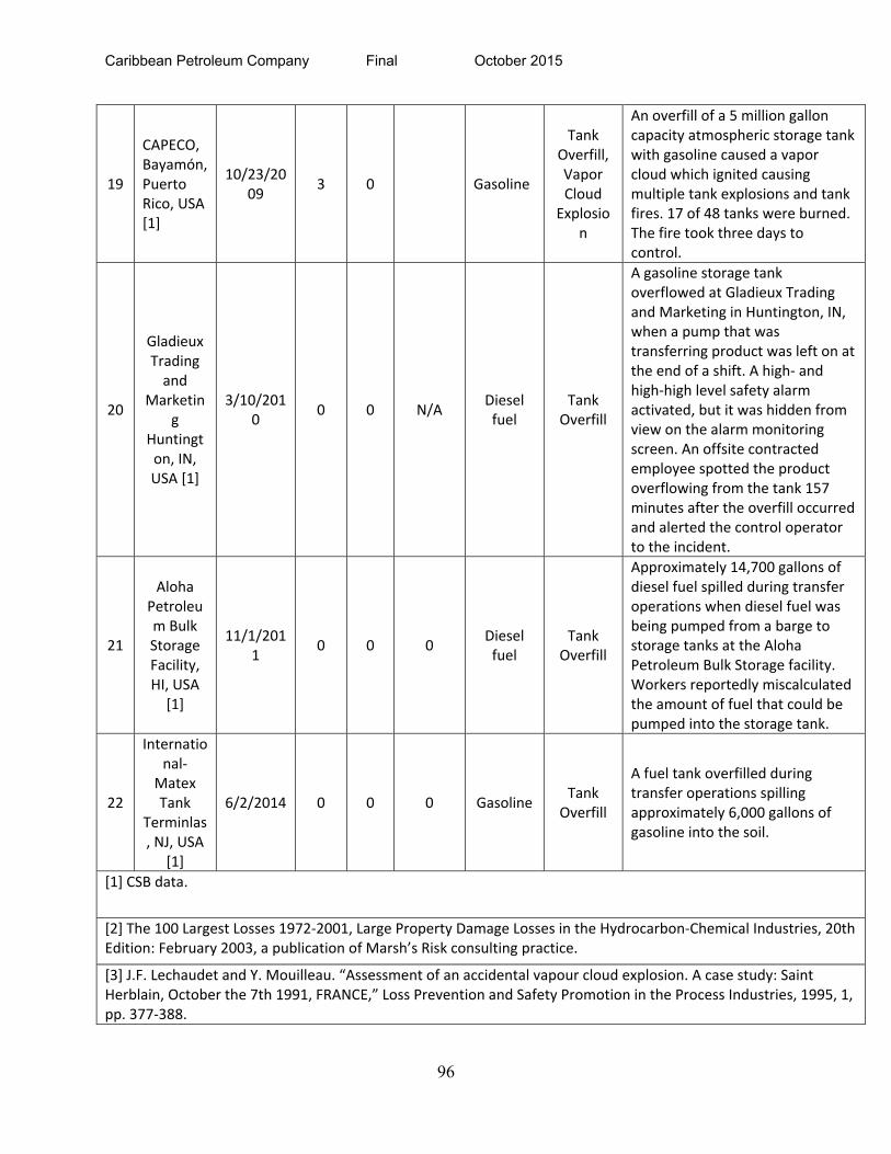
Caribbean Petroleum Company Final October 2015
96
19
CAPECO, Bayamón, Puerto Rico, USA [1]
10/23/2009
3 0 Gasoline
Tank Overfill, Vapor Cloud Explosio
n
An overfill of a 5 million gallon capacity atmospheric storage tank with gasoline caused a vapor cloud which ignited causing multiple tank explosions and tank fires. 17 of 48 tanks were burned. The fire took three days to control.
20
Gladieux Trading and
Marketing
Huntington, IN, USA [1]
3/10/2010
0 0 N/A Diesel fuel
Tank Overfill
A gasoline storage tank overflowed at Gladieux Trading and Marketing in Huntington, IN, when a pump that was transferring product was left on at the end of a shift. A high‐ and high‐high level safety alarm activated, but it was hidden from view on the alarm monitoring screen. An offsite contracted employee spotted the product overflowing from the tank 157 minutes after the overfill occurred and alerted the control operator to the incident.
21
Aloha Petroleum Bulk Storage Facility, HI, USA [1]
11/1/2011
0 0 0 Diesel fuel
Tank Overfill
Approximately 14,700 gallons of diesel fuel spilled during transfer operations when diesel fuel was being pumped from a barge to storage tanks at the Aloha Petroleum Bulk Storage facility. Workers reportedly miscalculated the amount of fuel that could be pumped into the storage tank.
22
International‐
Matex Tank
Terminlas, NJ, USA
[1]
6/2/2014 0 0 0 Gasoline Tank
Overfill
A fuel tank overfilled during transfer operations spilling approximately 6,000 gallons of gasoline into the soil.
[1] CSB data.
[2] The 100 Largest Losses 1972‐2001, Large Property Damage Losses in the Hydrocarbon‐Chemical Industries, 20th Edition: February 2003, a publication of Marsh’s Risk consulting practice.
[3] J.F. Lechaudet and Y. Mouilleau. “Assessment of an accidental vapour cloud explosion. A case study: Saint Herblain, October the 7th 1991, FRANCE,” Loss Prevention and Safety Promotion in the Process Industries, 1995, 1, pp. 377‐388.
Caribbean Petroleum Company Final October 2015
97
[4] M. Maremonti, G. Russo, E.Salzano, et al. “Postaccident Analysis of Vapour Cloud Explosions in Fuel Storage Areas,”” Trans IChemE 1999 77 (B) 360365. Persson, H. and Lennermark, A. 2004. Tank Fires Review of fire incidents 1951‐2003. SP Swedish National Testing and Research Institute. Accessed October 1, 2014.
[5] Eric M. Lenoir and John A. Davenport[v] “A Survey of Vapour Cloud Explosions, Second Update.” Hartford:” Industrial Risk Insurers, Paper No. 74d, 26th Annual Loss Prevention Symposium, AIChE, New Orleans, 1992.
[6] Lenoir and Davenport, 1992.
[7] Persson,H. and Lennermark, A. 2004. Tank Fires Review of fire incidents 1951‐2003. SP Swedish National Testing and Research Institute. Accessed October 1, 2014. Available at http://rib.msb.se/Filer/pdf%5C19108.pdf. [Edward C. Avant‐Frie Journal July 1974 (reprint from Fire Engineering April 1973); Herzog G. R. reprint Frie Journal July 1974; Mahley H. S. rreprint Hydrocarbon Proccessing, 1975.
[8] Persson, H. 3M Case History 7; Fire Engineering, August 1978.
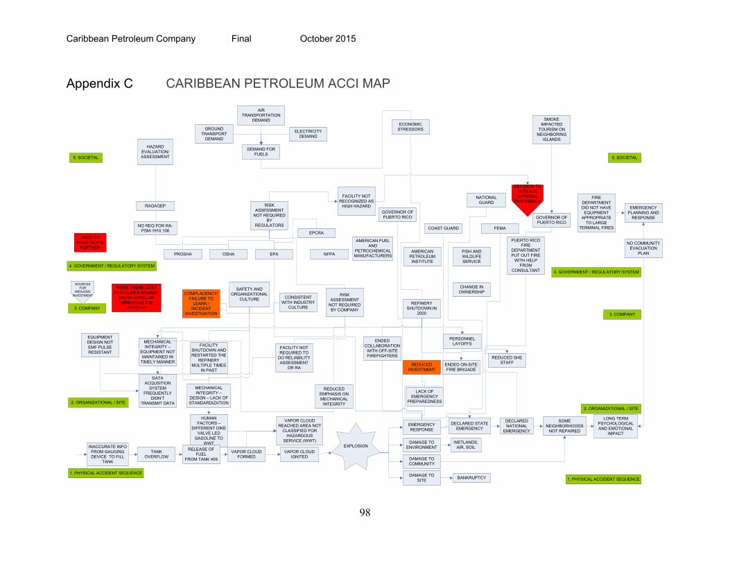
Caribbean Petroleum Company Final October 2015
98
Appendix C CARIBBEAN PETROLEUM ACCI MAP
TANK OVERFLOW
VAPOR CLOUD FORMED
VAPOR CLOUD IGNITED
1. PHYSICAL ACCIDENT SEQUENCE
2. ORGANIZATIONAL / SITE
3. COMPANY
4. GOVERNMENT / REGULATORY SYSTEM
5. SOCIETAL
HUMAN FACTORS –
DIFFERENT DIKE VALVE LED
GASOLINE TO WWT
VAPOR CLOUD REACHED AREA NOT
CLASSIFIED FOR HAZARDOUS
SERVICE (WWT)
DAMAGE TO COMMUNITY
DAMAGE TO SITE
DAMAGE TO ENVIRONMENTEXPLOSION
DATA ACQUSITION
SYSTEM FREQUENTLY
DIDN’T TRANSMIT DATA
MECHANICAL INTEGRITY –
EQUIPMENT NOT MAINTAINED IN
TIMELY MANNER
EQUIPMENT DESIGN NOT EMF PULSE RESISTANT
WERE THERE COST PRESSURES AGAINST
MAINTAINING OR IMPROVING THE
SYSTEM?
RELEASE OF FUEL
FROM TANK 409
INACCURATE INFO FROM GAUGING DEVICE TO FILL
TANK
OSHA EPA
RAGAGEP
PROSHAAMERICAN
PETROLEUM INSTITUTE
NFPA
AMERICAN FUEL AND
PETROCHEMICAL MANUFACTURERS
DEMAND FOR FUELS
AIR TRANSPORTATION
DEMAND
ELECTRICITY DEMAND
GROUND TRANSPORT
DEMAND
COMPLACENCY/FAILURE TO
LEARN /INCIDENT
INVESTIGATION
SAFETY AND ORGANIZATIONAL
CULTURE
NO REQ FOR RA-PSM-1910.106
HAZARD EVALUATION/ASSESSMENT
RISK ASSESSMENT
NOT REQUIRED BY COMPANY
RISK ASSESSMENT
NOT REQUIRED BY
REGULATORS
FACILITY NOT REQUIRED TO
DO RELIABILITY ASSESSMENT
OR RA
SOURCES FOR
REDUCED INVESTMENT
BANKRUPTCY
EMERGENCY RESPONSE
LACK OF EMERGENCY
PREPAREDNESS
1. PHYSICAL ACCIDENT SEQUENCE
2. ORGANIZATIONAL / SITE
3. COMPANY
4. GOVERNMENT / REGULATORY SYSTEM
5. SOCIETAL
REDUCED INVESTMENT
REFINERY SHUTDOWN IN
2000
ENDED COLLABORATION WITH OFF-SITEFIREFIGHTERS
ENDED ON-SITE FIRE BRIGADE
REDUCED EMPHASIS ON MECHANICAL
INTEGRITY
PERSONNEL LAYOFFS
ECONOMIC STRESSORS
CHANGE IN OWNERSHIP
NEED TO INVESTIGATE
FURTHER
REDUCED SHE STAFF
FACILITY NOT RECOGNIZED AS
HIGH HAZARD
FISH AND WILDLIFE SERVICE
DECLARED STATE EMERGENCY
DECLARED NATIONAL
EMERGENCY
PUERTO RICO FIRE
DEPARTMENT PUT OUT FIRE
WITH HELP FROM
CONSULTANT
GOVERNOR OF PUERTO RICO
FEMA
GOVERNOR OF PUERTO RICO
FIRE DEPARTMENT DID NOT HAVE
EQUIPMENT APPROPRIATE
TO LARGE TERMINAL FIRES
LONG TERM PSYCHOLOGICAL AND EMOTIONAL
IMPACT
SOME NEIGHBORHOODS
NOT REPAIRED
WETLANDS, AIR, SOIL
EMERGENCY PLANNING AND
RESPONSE
NO COMMUNITY EVACUATION
PLAN
COAST GUARD
NATIONAL GUARD
DECISION TO DECLARE NATIONAL
EMERGENCY
FACILITY SHUTDOWN AND RESTARTED THE
REFINERY MULTIPLE TIMES
IN PAST
MECHANICAL INTEGRITY –
DESIGN – LACK OF STANDARDIZATION
EPCRA
CONSISTENT WITH INDUSTRY
CULTURE
SMOKE IMPACTED
TOURISM ON NEIGHBORING
ISLANDS
Caribbean Petroleum Company Final October 2015
99
[Intentionally left Blank]