capital projects group · · 2017-06-08chapter 3 – traction power systems ... o/lap overlap...
TRANSCRIPT

Capital Projects Group
Performance Specifications for
Structures Passing Over Electrified Corridors
MX-ELEC STR-SPEC-2017-Rev3.0
May 12th 2017

3 Capital Projects Group, Network Infrastructure ‐ Electrification
Contents
Chapter 1 ‐ General ............................................................................................................................................ 4
1.1 Design Criteria Overview ..............................................................................................................................4
1.2 Abbreviations ...............................................................................................................................................4
1.3 Basis of Design .............................................................................................................................................7
1.4 Regulations, Codes, Standards and Guidelines (Latest Version) ..................................................................7
1.5 General Design Parameters .........................................................................................................................8
1.6 Design Life ....................................................................................................................................................8
1.7 Standardization ............................................................................................................................................8
1.8 Durability ......................................................................................................................................................8
Chapter 2 – Trackway Clearances ........................................................................................................................ 9
2.1 General .........................................................................................................................................................9
2.2 Vertical Clearances .......................................................................................................................................9
2.3 Horizontal Clearances ............................................................................................................................... 10
2.4 Clearance to Third Party Facilities ............................................................................................................. 10
Chapter 3 – Traction Power Systems ................................................................................................................. 10
3.1 General ...................................................................................................................................................... 10
3.2 Grounding and Bonding ............................................................................................................................ 11
3.3 Grounding Overpasses .............................................................................................................................. 13
Chapter 4 – Overhead Contact System (OCS) ..................................................................................................... 15
4.1 General ...................................................................................................................................................... 15
4.2 OCS Description and General Performance Requirements....................................................................... 15
4.3 OCS Structural Requirements ................................................................................................................... 16
Chapter 5 – Electrification Barriers .................................................................................................................... 16
5.1 General ...................................................................................................................................................... 16
5.2 Isolation Barrier Requirements ................................................................................................................. 17
Chapter 6 – Assurance ...................................................................................................................................... 17
6.1 General ...................................................................................................................................................... 17
6.2 Quality Assurance ..................................................................................................................................... 18
6.3 Inspection .................................................................................................................................................. 18
6.4 Maintenance ............................................................................................................................................. 18
6.5 Testing ....................................................................................................................................................... 18
6.6 Submittals ................................................................................................................................................. 18

4 Capital Projects Group, Network Infrastructure ‐ Electrification
Chapter 1 ‐ General
1.1 Design Criteria Overview
Purpose and Extent
Metrolinx intends to implement electrification over a large portion of their system: USRC, Barrie, Lakeshore West, Lakeshore East, Stouffville and Kitchener corridors. This will consist of a 25kVac system delivering power to trains by the use of an overhead contact system (OCS) in conjunction with power collection via a pantograph mounted on the roof of the vehicles. This performance specification is provided to establish the necessary measures to ensure the compatibility between current construction projects and the future Metrolinx electrification. The specifications and criteria within are intended to provide both the requirements of any structure passing over the electrified corridor and the recommendations on how to best achieve these requirements. This criteria will cover the requirements for OCS support and electrification grounding and bonding.
Other Metrolinx Electrification Project Documents
GO Transit Design Requirements Manual (DRM)
GO Track Standards RC‐0506‐02TRK
Performance Specifications for Electric Traction Enabling Works
MX‐ELEC TRAC EW‐SPEC‐2016 REV0
GO Electrification Enabling Works ET Standards
MX‐ELEC TRAC EW‐DW‐2016‐REV0
1.2 Abbreviations
AAR Association Of American Railroad CCZ Current Collector Zone
ac Alternating Current CGWC Copper Ground Wire (Covered)
ADJ Adjustment CL Center Line
AGWB Aluminum Ground Wire (Bare) CLR Clearance
AGWC Aluminum Ground Wire (Covered) CP Counterpoise
AREMA American Railway Engineering and Maintenance‐of‐Way Association
CSA Canadian Standards Association
ASTM American Society For Testing And Materials CW Contact Wire
ATF Autotransformer Feeder CWB Counterpoise Wire (Buried)
ATFZ Autotransformer Feeder Zone CWH Contact Wire Height
ATM Along Track Movement
AWG American Wire Gage dc Direct Current
oC Degree Celsius
BWA Balance Weight Termination Anchor DG Down Guy
DGW Down Guy Wire
C Celsius DIA Diameter

5 Capital Projects Group, Network Infrastructure ‐ Electrification
DIST Distribution LG Long
DRM Design Requirement Manual LPS Lightning Protection System
DVP Don Valley Parkway LV Low Voltage (120V Nominal Voltage)
DWG Drawing
m Meter
EA Emergency Alarm MF Maintenance Facility
EB Eastbound MGB Main Grounding Bar
EGC Equipment Grounding Conductor M/C Monitor And Control
EN European Standards MIN Minimum
ELEV Elevation mm Millimeter
ET Electric Traction MOD Modified
MP Milepost
FDN Foundation MPA Mid Point Anchor
FDRI Feeder Wire (Insulated) MPTW Mid Point Tie Wire
FRA Federal Railroad Administration MV Medium Voltage
FRE Fiberglass‐Reinforced Epoxy MW Messenger Wire
FTA Fixed Termination Anchor
FW Feeder Wire N Newton
NFPA National Fire Protection Association
GALV. Galvanized N.O. Normally Open
GBCW Grounding And Bonding Wire NOM Nominal
GENL General NTS Not To Scale
GTCC Go Transit Control Center
O/LAP Overlap
H/HT Height OCLZ Overhead Contact Line Zone
HORIZ Horizontal OCS Overhead Contact System
HRL High Rail OH Overhead
OOR Out‐Of‐Running
IEC International Electrotechnical Commission OESC Ontario Electrical Safety Code
IEEE Institute of Electrical and Electronics Engineers
IR In Running Pa Pascal
PITO Point Of Intersection Of The Turnout
JW Jumper Wire PS Paralleling Station
PSF Pound Per Square Foot
kg Kilogram PVC Polyvinyl Chloride
kg/M Kilogram Per Meter P.S. Point Of Switch

6 Capital Projects Group, Network Infrastructure ‐ Electrification
W Width
RAC Rail Association of Canada WP Working Point
RC Return Cable
REINF Reinforcement
rms Root‐mean‐squared
ROW Right‐Of‐Way
SCADA Supervisory Control And Data Acquisition
SM Single Mode
SPD Surge Protection Device
SQ Square
SS/SST Stainless Steel
STA Station Distance
STD/(S) Standard/Standards
STN Passenger Station
SW Static Wire
SWS Switching Station
T/ Top Of
TBD To Be Determined
TBS Transmission Backbone System
TOR Top Of Rail
TPF Traction Power Facility
TPSS Traction Power Substation
TRK Track
TRKS Tracks
TVM Ticket Vending Machine
TWA Tie Wire Anchor
TWPC Traction Wayside Power Control Cubicle
TYP Typical
UP Union Pearson Express
V Volt
VERT Vertical
VLD Voltage Limiting Device
VMS Visual Message Sign
7 Capital Projects Group, Network Infrastructure ‐ Electrification
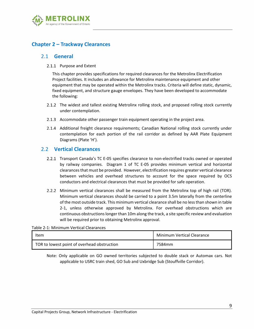
1.3 Basis of Design
The Metrolinx Electrification system shall be a 2 x 25kVac autotransformer traction
electrification system (With the exception of the Guideway to Pearson Airport which shall be
a 1x25kVac system). All proposed projects crossing over the electrified corridor shall include
provisions to protect public safety and to accommodate bare or insulated autotransformer
feeders, OCS wire support and the traction power return system.
1.4 Regulations, Codes, Standards and Guidelines (Latest Version)
Federal and National Regulations and Codes
Transport Canada – Standard Respecting Railway Clearances TC E‐05
Canadian Standards Association (CSA)
CAN/CSA C22.1 Canadian Electrical Code, part 1
CAN/CSA C22.2 No 0 General Requirements, Canadian Electrical Code, part 2
CAN/CSA C22‐3 No. 8 Railway Electrification Guidelines.
CAN/CSA C2.3 1‐10 Overhead Systems
CAN/CSA C22.2 NO.0.4 ‐ Bonding and Grounding of Electrical Equipment
CAN/CSA C22.3 NO.2 ‐ General Grounding Requirements and Grounding
Requirements for Electrical Supply Stations
CAN/CSA B72 – M87 (Reaffirmed 2008) – Installation Code for Lightning
Protection Systems.
Provincial Regulations and Codes
OESC Ontario Electrical Safety Code
Standards and Guidelines
American Railway Engineering and Maintenance‐of‐Way Association (AREMA)
Manual for Railway Engineering (Chapter 33 – Electrical Energy Utilization)
Railway Association of Canada (RAC) Standards
IEEE 80: Guide for Safety in ac Substation Grounding;
EN 50122‐1: Railway Applications, Fixed Installations – Protective Provisions
Relating to Electrical Safety and Grounding;
IEC 60479: Effects of Current on Human Beings and Livestock
NFPA 780: Standard for Lightning Protection Systems
IEC 60305‐1: Protection Against Lightning

8 Capital Projects Group, Network Infrastructure ‐ Electrification
1.5 General Design Parameters
Units of Measurement – The Metric system shall be used
1.6 Design Life
Electrification elements (such as Ground Conductors and any provisional OCS attachments)
installed within the overbuild shall have a design life that matches or exceeds that of the
adjacent structural elements and no less than 30 years.
Electrification elements exposed to climate shall be reasonably protected from the
environment in the period before the electrification contractor begins construction and have
a design life of no less than 30 years.
1.7 Standardization
Design shall use standard materials and equipment where possible. Standardization ensures
ease of procurement and inventory management, minimizes staff training, optimizes
maintenance, and avoids long lead times for materials, equipment, and components.
Equipment and materials shall meet industry standards, be available off the shelf, and
supplied by established manufacturers. Selection of equipment and materials shall consider
long‐term costs, ease of construction and maintenance, and readily available technical
support.
Effort shall be made to standardize the appearance of all exposed elements, including
electrification barriers, such that there is a unified aesthetic between all visible structures.
Direction will be given from Metrolinx on final finish.
1.8 Durability
Design shall assess potential for deterioration of materials and assemblies, including
deterioration specific to exposure to the environment and future climate. Materials and detail
assemblies shall be durable with minimal maintenance and repairs throughout their design
life. For surface and assembly for which appearance is important, durability shall include
maintenance required to preserve appearance. Design shall take into account the following
aspects of durability:
Control of moisture
Control of corrosion (including material compatibility)
Control of exposure to industrial and vehicular pollution
Minimize damage from wear and tear
Ease of repair; ease of access
Protect grounding appurtenances from vandalism
9 Capital Projects Group, Network Infrastructure ‐ Electrification
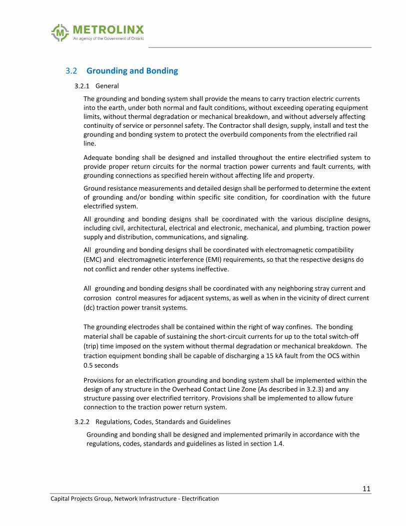
Chapter 2 – Trackway Clearances
2.1 General
Purpose and Extent
This chapter provides specifications for required clearances for the Metrolinx Electrification Project facilities. It includes an allowance for Metrolinx maintenance equipment and other equipment that may be operated within the Metrolinx tracks. Criteria will define static, dynamic, fixed equipment, and structure gauge envelopes. They have been developed to accommodate the following:
The widest and tallest existing Metrolinx rolling stock, and proposed rolling stock currently
under contemplation.
Accommodate other passenger train equipment operating in the project area.
Additional freight clearance requirements; Canadian National rolling stock currently under
contemplation for each portion of the rail corridor as defined by AAR Plate Equipment
Diagrams (Plate ‘H’).
2.2 Vertical Clearances
Transport Canada’s TC E‐05 specifies clearance to non‐electrified tracks owned or operated
by railway companies. Diagram 1 of TC E‐05 provides minimum vertical and horizontal
clearances that must be provided. However, electrification requires greater vertical clearance
between vehicles and overhead structures to account for the space required by OCS
conductors and electrical clearances that must be provided for safe operation.
Minimum vertical clearances shall be measured from the Metrolinx top of high rail (TOR).
Minimum vertical clearances should be carried to a point 3.5m laterally from the centerline
of the most outside track. This minimum vertical clearance shall be no less than shown in table
2‐1, unless otherwise approved by Metrolinx. For overhead obstructions which are
continuous obstructions longer than 10m along the track, a site specific review and evaluation
will be required prior to obtaining Metrolinx approval.
Table 2‐1: Minimum Vertical Clearances
Item Minimum Vertical Clearance
TOR to lowest point of overhead obstruction 7584mm
Note: Only applicable on GO owned territories subjected to double stack or Automax cars. Not
applicable to USRC train shed, GO Sub and Uxbridge Sub (Stouffville Corridor).

10 Capital Projects Group, Network Infrastructure ‐ Electrification
2.3 Horizontal Clearances
Minimum horizontal clearances shall be measured from the track centerline (TCL) of the
closest Metrolinx track to the feature being cleared.
Table 2‐2: Minimum Horizontal Clearances
Item Minimum Horizontal Clearance
TCL to face of OCS Pole 29001mm + 25.4mm*(DOC)
Notes:
1. Where 2900mm cannot be met, a reduced clearance can be submitted to Metrolinx for approval.
2. DOC = Degree of Curve SE = Superelevation (mm) YD = Vertical height of dynamic envelope (mm)
2.4 Clearance to Third Party Facilities
Where facilities owned and operated by third parties are involved, the clearance requirement
of this document and those of the third party shall be compared and the larger dimension
used.
Chapter 3 – Traction Power Systems
3.1 General
Purpose and Extent
This section provides the requirements for grounding and bonding of structures passing over Metrolinx corridors for coordination with the future electrification and its traction power return system (TPRS). The TPRS consists of various components (such as running rails, rail bonding cables, aerial static (ground) wire, and earth) to allow current from the electric train vehicle to ultimately return to its supply substation source under both normal operating conditions and under fault conditions.
Due to the presence of electric trains, its open wire distribution and traction return currents in the rails, it is necessary to provide grounding and bonding network at all accessible elements along the right‐of‐way to: (i) facilitate an equal‐potentiality for all normally‐non‐current‐carrying‐conductive equipment and structures, and (ii) ensure flow of all fault current (including lightning) towards the earth to protect personnel and equipment from damage.
EMI Protection
The 25kVac overhead catenary wires and auto‐transformer feeder wires may produce an
electromagnetic field which could affect elements on the overbuild. It is the contractor’s
responsibility to protect any equipment which could be affected by this electromagnetic field.
11 Capital Projects Group, Network Infrastructure ‐ Electrification
3.2 Grounding and Bonding
General
The grounding and bonding system shall provide the means to carry traction electric currents into the earth, under both normal and fault conditions, without exceeding operating equipment limits, without thermal degradation or mechanical breakdown, and without adversely affecting continuity of service or personnel safety. The Contractor shall design, supply, install and test the grounding and bonding system to protect the overbuild components from the electrified rail line.
Adequate bonding shall be designed and installed throughout the entire electrified system to provide proper return circuits for the normal traction power currents and fault currents, with grounding connections as specified herein without affecting life and property.
Ground resistance measurements and detailed design shall be performed to determine the extent of grounding and/or bonding within specific site condition, for coordination with the future electrified system.
All grounding and bonding designs shall be coordinated with the various discipline designs, including civil, architectural, electrical and electronic, mechanical, and plumbing, traction power supply and distribution, communications, and signaling.
All grounding and bonding designs shall be coordinated with electromagnetic compatibility
(EMC) and electromagnetic interference (EMI) requirements, so that the respective designs do
not conflict and render other systems ineffective.
All grounding and bonding designs shall be coordinated with any neighboring stray current and
corrosion control measures for adjacent systems, as well as when in the vicinity of direct current
(dc) traction power transit systems.
The grounding electrodes shall be contained within the right of way confines. The bonding
material shall be capable of sustaining the short‐circuit currents for up to the total switch‐off
(trip) time imposed on the system without thermal degradation or mechanical breakdown. The
traction equipment bonding shall be capable of discharging a 15 kA fault from the OCS within
0.5 seconds
Provisions for an electrification grounding and bonding system shall be implemented within the design of any structure in the Overhead Contact Line Zone (As described in 3.2.3) and any structure passing over electrified territory. Provisions shall be implemented to allow future connection to the traction power return system.
Regulations, Codes, Standards and Guidelines
Grounding and bonding shall be designed and implemented primarily in accordance with the regulations, codes, standards and guidelines as listed in section 1.4.

12 Capital Projects Group, Network Infrastructure ‐ Electrification
Overhead Contact Line Zone (OCLZ)
A live broken contact line, or live parts of a broken or de‐wired pantograph or energized
fragments, may accidentally come into contact with wayside structures and equipment. As
derived from European standard EN 50122‐1, the overhead contact line zone (OCLZ) is used to
define the area in which normally non‐current‐carrying metallic components in this zone are to
be either directly grounded or bonded to the traction power return system to provide for
personnel safety. Metallic objects and equipment at structures near or passing over the
electrified corridor that are within the OCLZ are to be properly grounded and bonded. The
grounding and/or bonding configuration to be employed is dependent upon the equipment
involved.
The OCLZ shall be taken as an area 2.0 m horizontally from any electrified part or wire, and
vertically from that part to the ground directly below. This zone shall also include a 4.0 m zone
horizontally from any overhead catenary wire (Contact or Messenger).
Commercial/Utility Electrical Distribution Systems
It is recommended that the ground of commercial/utility electrical distribution systems not be
interconnected with traction return system. This is due to the potential damaging effects if the
traction power system were to experience a fault in the overpass area. Under such an event,
the commercial/utility system equipment and other low voltage electrical equipment could
experience damage.
Non‐metallic raceways should be used when routing such commercial/utility power circuits on
the overpass structure or in areas within the OCLZ.
3rd Party Utilities in the OCLZ
It is recommended to keep 3rd party utilities outside the OCLZ area whenever possible. New 3rd
party utilities may only be installed within the OCLZ with Metrolinx approval. If approval is
granted, the means required to properly protect the railroad and the utility are outlined below:
Underground Utility Installations
New buried 3rd party utilities under the tracks shall be installed in a steel casing
pipe with its ends sealed with non‐shrinkable grout. This is to facilitate utility
replacement as well as protect the railroad track bed infrastructure.
Utility Installations on the Overpass Structure
New 3rd party utilities installed on the overpass structure shall have a carrier
pipe enclosed in a steel casing pipe that is isolated from the carrier pipe by
approved insulators. The steel casing pipe shall then be bonded to the traction
return system (overhead static wire) via #4/0 AWG copper wire.
Exposed Utility Installations Parallel the Railroad Right of way within the OCLZ
New exposed 3rd party utilities that run exposed parallel to the railroad right
of way inside the OCLZ shall have a carrier pipe enclosed in a steel casing pipe
13 Capital Projects Group, Network Infrastructure ‐ Electrification
that is isolated from the carrier pipe by approved insulators. The steel casing
pipe shall have insulating collars at approximately 305m with each section
having its midpoint bonded to the nearest OCS structure via #4/0 AWG copper
wire.
3.3 Grounding Overpasses
All overpasses consisting of steel structures including pedestrian walkways, architectural treatments or other
metallic structures crossing over the track shall have provisions included for the bonding and grounding of
these elements. Concrete overpasses shall be provided with attachment points for future conductive flash
plates to be attached to them. The design of these elements shall be coordinated with Metrolinx
Electrification.
Structure Grounding
Any metallic structural components installed above the electrified corridor shall be made
electrically continuous and shall be bonded and grounded to achieve a maximum 25Ω resistance
to ground. For non‐roadway structures or structures which are readily used by pedestrians, this
maximum ground resistance shall be 5Ω.
Any metallic walkway/catwalk shall be effectively and continuously bonded along its route and
to the designated column or structure interaction point for the connection to the traction power
return system. This continuity connection shall be a minimum of #4/0 copper in size and
conductivity.
Step and Touch Potentials on Walkways of Overpass Structures
An electrical safety analysis shall take into account criteria for the ground potential rise (refer to
IEEE Standard – 80). The analysis shall be undertaken to assess which normally non‐current
carrying conductive parts need to be grounded and bonded, and the appropriate method of
implementation shall be identified to ensure that the step and touch potentials are within
permissible limits indicated below, which has been derived from EN 50122‐1: 2011 section 9.2.2.

14 Capital Projects Group, Network Infrastructure ‐ Electrification
Duration of Current Flow (seconds) Permissible Voltage in V (rms)
0.02 865
0.05 835
0.1 785
0.2 645
0.3 480
0.4 295
0.5 220
0.6 180
< 0.7 155
0.7 90
0.8 85
0.9 80
1.0 75
≤ 300 65
> 300
(where accessible to the public
under all power supply feeding)
60
> 300
(in workshops and similar locations) 25

15 Capital Projects Group, Network Infrastructure ‐ Electrification
Connection to the Traction Power Return System
The overpass and all bonded elements shall be grounded through their foundations to achieve a
maximum 25Ω resistance to ground. In addition to this, the overpass shall be bonded to the
Traction Power return system via the OCS static wire. This connection shall be made by the
electrification installer and shall be facilitated by leaving an interaction point exposed or by
leaving an appropriate length of ground conductor coiled and protected for use of the future
electrification installer. This ground conductor shall be a minimum of #4/0 copper in size and
conductivity.
Step and Touch Mitigation
Metallic items outside of the OCLZ shall maintain a 2m clearance from objects bonded to the
traction power return system. This separation is to mitigate the risk of a person being in contact
with both objects during a fault. If this separation cannot be maintained, the additional metallic
object shall be bonded to the adjacent object such that they are kept at the same potential. Effort
should be made to prevent a knock‐on effect of bonding multiple objects outside of the OCLZ.
Chapter 4 – Overhead Contact System (OCS)
4.1 General
Purpose and Extent
An OCS support system of any type may require attachments to an overpass. This can be achieved in several ways, however, the preference is to allow for the greatest amount of flexibility for the electrification installer’s future attachment.
4.2 OCS Description and General Performance Requirements
General OCS Arrangement
A typical OCS support structure consists of either a simple OCS pole or a portal structure. All OCS wires, and ancillary wires, including feeders and static wires, are attached to these structures with wire support assemblies. A typical OCS pole consists of a free‐standing pole to which a cantilever assembly is attached to support the contact and messenger wires over the vehicle pantograph. Wire attachment assemblies for ancillary wires are also supported on the OCS poles. A typical portal consists of two (2) columns with a crossbeam between them which supports catenary assemblies. Each electrified track may have one or more drop pipes from which cantilever assemblies and wire attachment assemblies will be supported.
OCS Support at Overpasses
Where passing under an overpass the OCS may be supported from drop pipes from the superstructure or from OCS structures adjacent to the overpass. OCS attachments to the overpass shall not require cutting or drilling elements of the overpass structure. Exception to this requirement, requires the approval of both Metrolinx and the bridge owner.

16 Capital Projects Group, Network Infrastructure ‐ Electrification
Spacing of OCS Supports
Project specific locations of future OCS support shall be coordinated with Metrolinx Electrification. OCS Supports will be placed with a maximum span of 60m between supports in tangent track. An average span of 45m‐55m is expected in the provided OCS layout, although this may decrease if site constraints require. Any modifications to the OCS layout requires approval and coordination with Metrolinx Electrification.
4.3 OCS Structural Requirements
General
Provisions for future OCS supports shall be designed with the future OCS considerations included. The intent of these provisions is to allow the future electrification contractor to install the remaining elements required to support the OCS without cutting or drilling elements of the overpass structure.
OCS Support Requirements
Deflection of the support structure shall be kept at a minimum of 75mm in the across‐track
direction at the height of the future catenary supports. This shall be calculated as the deflection
of the steel in addition to any effects of rotation at the top of foundations. This deflection will be
calculated at a height of 7000mm above the top of high rail (TOR).
Wire loading
Loading imposed from the OCS to integrated overpass elements shall be provided by Metrolinx Electrification. These loads will include vertical weight, curve pull from tensioned wires and wind‐on‐wire loading, and shall be assumed to be acting in a condition and orientation as to result in a worst case loading condition combined with overpass element loading.
Chapter 5 – Electrification Barriers
5.1 General
Purpose and Extent
Structures Passing over the Metrolinx corridor in areas of electrification will have to span over electrified catenary wires as well as other electrified parts such as feeder wires and support assemblies. As such it is a matter of public safety that proper isolation from these electrified parts is assured. All accessible surfaces shall be protected by means of an isolation barrier.

17 Capital Projects Group, Network Infrastructure ‐ Electrification
5.2 Isolation Barrier Requirements
Any accessible standing surface which passes over an electrified track shall be protected by a
barrier to prevent contact with electrified parts. This barrier shall meet the following
minimum requirements:
This barrier shall extend a minimum of 5.0 m horizontally beyond the
centerline of track or 3.0 m horizontally beyond the outermost electrified wire,
whichever is further.
This barrier shall be solid. There can be no gaps, holes or mesh which would
allow a member of the public to intentionally or unintentionally pass an object
through the barrier.
This barrier shall extend a minimum of 2.0 m vertically from the adjacent
standing surface. This barrier shall be reasonably non‐climbable and contain
no elements which can be readily used as a step. If a railing is employed that
could be used as a step then the barrier must extend 2.0 m vertically from that
surface.
This barrier shall be either metallic or non‐conductive.
o If metallic the barrier shall be effectively and continuously bonded along its route for connection to the traction power return system similar to that of the catwalk/walkway requirements (section 3.3.1)
o If non‐conductive the barrier shall be provided with tin‐plated copper ground strips of 75 mm wide x 6 mm thick minimum, continuous along the perimeter (on the top and ends) which shall be bonded to the traction power return system similar to that of the catwalk/walkway requirements (section 3.3.1)
Chapter 6 – Assurance
6.1 General
Purpose and Extent
This chapter provides requirements for the quality assurance, inspection, record keeping and documentation required during the construction of provisional electrification elements. The intent is to provide assurance for the future electrification installer to utilize these items which have had advanced installation.

18 Capital Projects Group, Network Infrastructure ‐ Electrification
6.2 Quality Assurance
Ground resistance test procedures and test results must be submitted to Metrolinx for
approval prior to any work being performed.
6.3 Inspection
Cooperate with the Construction Manager and furnish services as may be required for
inspecting and obtaining data. Cooperate and Coordinate site inspection with Metrolinx,
Metrolinx Electrification Group, their representatives and Electrification Technical Advisor.
Grounding and Bonding
Grounding and Bonding elements shall be inspected prior to embedment in
concrete and tested as per the requirements in section 6.5.
Visual inspection (Photographic or Video) of embedded Grounding and
Bonding provisions shall be performed prior to the pouring of any concrete
6.4 Maintenance
Maintenance of the overpass and its associated barriers shall be coordinated with Metrolinx.
Any work performed within 8.0 m of an electrified part (including but not
limited to: catenary wires, feeder wires, support assemblies and other
hardware) will require protection and coordination with Metrolinx
Electrification.
Any work performed within 3.0 m of an unguarded electrified part will require
the de‐energization of the system in the area. This de‐energization shall be
coordinated with and performed by Metrolinx Electrification.
6.5 Testing
Grounding and Bonding
Ground resistance testing shall be performed in accordance with a Ground
Resistance test Procedures submitted to Metrolinx
6.6 Submittals
Documentation for provisional electrification items shall be provided to Metrolinx as
assurance for the future electrification installer. This documentation shall be provided as a
single, separate package such that the future electrification installer will have a complete set
of documents for assurance.
Grounding and Bonding
Shop Drawings: Shall include a layout showing the location and type of each
grounding conductor and connection.
19 Capital Projects Group, Network Infrastructure ‐ Electrification
Installation drawings showing grounding and bonding layout of system with all
interconnections.
Catalog Cuts shall be provided for all grounding material.
Ground Resistance test results and GPR Studies shall be provided.
END OF SECTION