capsat transceiver 3020c installation - ironbarque documentation/equipment manuals/thran… ·...
TRANSCRIPT

Maritime Capsat Transceiver
TT-3020C
Installation Manual


Thrane & ThraneThrane & ThraneThrane & ThraneThrane & Thrane
Maritime Capsat Transceiver
TT-3020C
Installation Manual
Copyright Thrane & Thrane A/S
ALL RIGHTS RESERVED

Information in this document is subject to change without noticeand does not represent a commitment on the part of Thrane &Thrane A/S.
© 2000 Thrane & Thrane A/S. All right reserved. Printed in Den-mark.
Document Number TT98-107880-C.
Release Date: 25. July 2000

Safety SummarySafety SummarySafety SummarySafety SummaryThe following general safety precautions must be observed during all phases of
operation, service and repair of this equipment. Failure to comply with theseprecautions or with specific warnings elsewhere in this manual violates safety
standards of design, manufacture and intended use of the equipment.Thrane & Thrane A/S assumes no liability for the customers failure to comply with
these requirements.
GROUND THE EQUIPMENTGROUND THE EQUIPMENTGROUND THE EQUIPMENTGROUND THE EQUIPMENTTo minimise shock hazard, the equipment chassis and cabinet must be connected to
an electrical ground
DO NOT OPERATE IN AN EXPLOSIVE ATMOSPHEREDO NOT OPERATE IN AN EXPLOSIVE ATMOSPHEREDO NOT OPERATE IN AN EXPLOSIVE ATMOSPHEREDO NOT OPERATE IN AN EXPLOSIVE ATMOSPHEREDo not operate the equipment in the presence of flammable gases or fumes. Opera-tion of any electrical equipment in such an environment constitutes a definite safety
hazard.
KEEP AWAY FROM LIVE CIRCUITSKEEP AWAY FROM LIVE CIRCUITSKEEP AWAY FROM LIVE CIRCUITSKEEP AWAY FROM LIVE CIRCUITSOperating personnel must not remove equipment covers. Component replacementand internal adjustment must be made by qualified maintenance personnel. Do not
replace components with the power cable connected. Under certain conditions,dangerous voltages may exist even with the power cable removed. To avoid injuries,
always disconnect power and discharge circuits before touching them.
DO NOT SERVICE OR ADJUST ALONEDO NOT SERVICE OR ADJUST ALONEDO NOT SERVICE OR ADJUST ALONEDO NOT SERVICE OR ADJUST ALONEDo not attempt internal service or adjustments unless another person, capable of
rendering first aid resuscitation, is present.
DO NOT SUBSTITUTE PARTS OR MODIFY EQUIPMENTDO NOT SUBSTITUTE PARTS OR MODIFY EQUIPMENTDO NOT SUBSTITUTE PARTS OR MODIFY EQUIPMENTDO NOT SUBSTITUTE PARTS OR MODIFY EQUIPMENTBecause of the danger of introducing additional hazards, do not substitute parts or
perform any unauthorized modification to the equipment.
SAFETY DISTANCE FOR THE ANTENNA UNITSAFETY DISTANCE FOR THE ANTENNA UNITSAFETY DISTANCE FOR THE ANTENNA UNITSAFETY DISTANCE FOR THE ANTENNA UNITMinimum safety distance of 2 feet (61 cm) from the Antenna.
Radiated intensity at 0.56m is 10 W/m2
Radiated intensity at 0.36m is 25 W/m2
Radiated intensity at 0.18m is 100 W/m2
COMPASS SAFCOMPASS SAFCOMPASS SAFCOMPASS SAFE DISTANCEE DISTANCEE DISTANCEE DISTANCEMinimum safety distance of 50 cm from the TT-3020C transceiver

This page is intentionally left blank

Table of ContentsTable of ContentsTable of ContentsTable of Contents
25-Jul-0025-Jul-0025-Jul-0025-Jul-00 Page Page Page Page iiii
Table of Contents
1 Introduction....................................................................................... 1-11.1 Initial Inspection ....................................................................... 1-11.2 Storage ..................................................................................... 1-21.3 Repackaging for shipment........................................................ 1-2
2 Installation - TT-3020C....................................................................... 2-12.1 Technical specifications............................................................ 2-12.2 Compass Safe Distance............................................................. 2-32.3 Power requirements ................................................................ 2-4
2.3.1 Fuse ............................................................................ 2-42.4 Functional description .............................................................. 2-4
2.4.1 On/Off features ........................................................... 2-42.4.2 Front indicators and buttons........................................ 2-5
2.5 Connectors ............................................................................... 2-72.5.1 Power connector ......................................................... 2-72.5.2 DTE Communication port ............................................ 2-92.5.3 I/O Connector ........................................................... 2-112.5.4 Printer port................................................................ 2-152.5.5 Grounding ................................................................ 2-17
2.6 Built-in GPS (optional) ............................................................ 2-172.6.1 GPS specifications..................................................... 2-18
2.7 Mounting bracket ................................................................... 2-18
3 System Installation............................................................................. 3-13.1 Power requirements ................................................................ 3-1
3.1.1 Fuses........................................................................... 3-23.2 Compass Safe Distance............................................................. 3-33.3 Antennas................................................................................... 3-5
3.3.1 TT-3005M Maritime Antenna ....................................... 3-53.3.2 TT-3005A Maritime Antenna...................................... 3-103.3.3 TT-3001B Maritime Antenna ...................................... 3-153.3.4 Antenna Mounting Considerations ............................ 3-183.3.5 Safety Distance for Antenna Units.............................. 3-21
3.4 TT-3606E Message Terminal................................................... 3-233.4.1 Connectors................................................................ 3-233.4.2 TT-3601E keyboard................................................... 3-253.4.3 Specifications............................................................ 3-263.4.4 Mounting................................................................... 3-27

Table of ContentsTable of ContentsTable of ContentsTable of Contents
Page Page Page Page iiiiiiii 25-Jul-0025-Jul-0025-Jul-0025-Jul-00
3.5 TT-3680B Power Supply...........................................................3-293.5.1 Mounting ...................................................................3-29
3.6 TT-3608A Hard Copy Printer ...................................................3-313.6.1 Mounting plate...........................................................3-323.6.2 Roll Paper Stand.........................................................3-323.6.3 Mounting ...................................................................3-34
3.7 TT-3608G Printer Unit..............................................................3-353.7.1 Configuration.............................................................3-363.7.2 Installation .................................................................3-383.7.3 Connectors ................................................................3-383.7.4 Cable.........................................................................3-393.7.5 Specifications.............................................................3-41
3.8 TT-3042C Remote Alarm/Distress Box (optional) ....................3-423.8.1 Mounting ...................................................................3-45
3.9 TT-3042D Remote Alarm / Printer Unit ....................................3-483.9.1 Configuration.............................................................3-493.9.2 Installation .................................................................3-523.9.3 Connectors ................................................................3-523.9.4 Cable.........................................................................3-533.9.5 Specifications.............................................................3-55
3.10 Distress Button Test .................................................................3-563.10.1 TT-3020C Transceiver................................................3-563.10.2 TT-3042C Remote Alarm/Distress Box .......................3-573.10.3 TT-3042D Remote Alarm Distress Box ........................3-57
3.11 General interconnect information ...........................................3-58
4 System Generation.............................................................................4-14.1 Terminal Mode..........................................................................4-1
4.1.1 TT-3606E Message Terminal ........................................4-14.1.2 Computerised equipment/handheld terminals ............4-1
4.2 Initialise System Parameters......................................................4-24.2.1 Entering your mobile number......................................4-24.2.2 Altering baudrate and protocol settings ......................4-34.2.3 Antenna voltage settings..............................................4-4
5 Commissioning ..................................................................................5-15.1 Introduction...............................................................................5-15.2 The first Login ...........................................................................5-15.3 Link Test....................................................................................5-25.4 Details of a Link Test..................................................................5-2
6 Index..................................................................................................6-1

Table of FiguresTable of FiguresTable of FiguresTable of Figures
25-Jul-0025-Jul-0025-Jul-0025-Jul-00 Page Page Page Page iiiiiiiiiiii
Table of Figures
Figure 1 TT-3020C Maritime Capsat Transceiver ........................................ 1-1Figure 2TT-3020C Capsat Transceiver rear panel ....................................... 2-7Figure 3 TT-3020C Capsat Transceiver mounting plate. ............................ 2-19Figure 4 Front panel of the TT-3020C Capsat Transceiver withmounting bracket ...................................................................................... 2-19Figure 5 TT-3005M Maritime Antenna ......................................................... 3-5Figure 6 TT-3005M 1’’ Tube Mounting ......................................................... 3-9Figure 7 TT-3005A Maritime Antenna ........................................................ 3-10Figure 8 TT-3005A 1.5’’ tube mounting...................................................... 3-14Figure 9 TT-3001B opt. 001 Maritime Antenna ........................................... 3-15Figure 10 TT-3001B-opt. 001 1.5’’ Tube mounting...................................... 3-18Figure 11 Inmarsat-C Antenna Mounting ................................................... 3-20Figure 12 Inmarsat-C Antenna mounting near pole or funnel .................... 3-21Figure 13 TT-3606E Message Terminal...................................................... 3-23Figure 14 TT-3606E Rear Connectors ........................................................ 3-24Figure 15 Mounting holes for TT-3606E ..................................................... 3-27Figure 16 TT-3606E Mounting Bracket....................................................... 3-28Figure 17 TT-3680B - 200W power supply. ................................................ 3-29Figure 18 Mounting holes for TT-3680B ..................................................... 3-30Figure 19 TT-3608A Hard copy printer ...................................................... 3-31Figure 20 TT-3608A Paper Roll Stand......................................................... 3-32Figure 21 Mounting holes for TT-3608A..................................................... 3-34Figure 22 TT-3608G Remote Printer Unit ................................................... 3-35Figure 23 TT-3042C Remote Alarm/Distress Box ....................................... 3-42Figure 24 TT-3042C Outline drawing......................................................... 3-45Figure 25 TT-3042C Outline drawing with console bracket ....................... 3-46Figure 26 TT-3042C Mounting stencil. ....................................................... 3-47Figure 27 TT-3042D Remote Alarm Distress Box / Local Printer................. 3-48Figure 28 Interconnection diagram ........................................................... 3-59

Table of FiguresTable of FiguresTable of FiguresTable of Figures
Page Page Page Page iviviviv 25-Jul-0025-Jul-0025-Jul-0025-Jul-00
This page is intentionally left blank

Table of TablesTable of TablesTable of TablesTable of Tables
25-Jul-0025-Jul-0025-Jul-0025-Jul-00 Page Page Page Page vvvv
Table of Tables
Table 1 TT-3020C technical specifications................................................... 2-2Table 2 Inmarsat-C Protocol support. .......................................................... 2-3Table 3 TT-3020C power requirements ....................................................... 2-4Table 4 TT-3020C Capsat Transceiver ON/OFF overview ........................... 2-5Table 5 TT-3020C Capsat Transceiver DC Power Connector pinassignment .................................................................................................. 2-8Table 6 Automatic baudrate settings ........................................................... 2-9Table 7 TT-3020C X3 pin assignment......................................................... 2-10Table 8 TT-3020C X4 pin assignment......................................................... 2-12Table 9 Printer port (X5) pin assignment ................................................... 2-16Table 10 GPS Specifications ...................................................................... 2-18Table 11 Capsat System component power requirements ........................... 3-2Table 12 Capsat System Fuses..................................................................... 3-3Table 13 Compass Safe Distance ................................................................. 3-4Table 14 TT-3005M technical specifications. ............................................... 3-7Table 15 TT-3020C Capsat Transceiver Antenna Cable types (TNC -TNC) for TT-3005M. ..................................................................................... 3-8Table 16 TT-3005A technical specifications. .............................................. 3-12Table 17 TT-3020C Capsat Transceiver Antenna Cable types (TNC -TNC) for TT-3005A antenna. ...................................................................... 3-13Table 18 TT-3001B opt. 001 Technical Specifications................................. 3-16Table 19 TT-3020C Capsat Transceiver Antenna Cable types (N - TNC)for TT-3001B opt. 001................................................................................. 3-17Table 20 Radiated intensity ....................................................................... 3-22Table 21 TT-3606E Power Connector......................................................... 3-24Table 22 TT-3606E Message Terminal Specifications ................................ 3-26Table 23 TT-3608G DIP switch settings. ..................................................... 3-37Table 24 TT-3608G Power Connector ........................................................ 3-38Table 25 TT-3608G I/O Connector............................................................. 3-39Table 26 TT-3608G Technical Specifications.............................................. 3-41Table 27 TT-3042C and Satellite Communication Unit inter-connection .... 3-43Table 28 TT-3042C Technical Specifications.............................................. 3-44

Table of TablesTable of TablesTable of TablesTable of Tables
Page Page Page Page vivivivi 25-Jul-0025-Jul-0025-Jul-0025-Jul-00
Table 29 TT-3042D DIP switch settings.......................................................3-51Table 30 TT-3042D Power Connector.........................................................3-52Table 31 TT-3042D I/O Connector..............................................................3-53Table 32 TT-3042D Technical Specifications ..............................................3-55Table 33 Antenna voltage configuration.......................................................4-4

Initial InspectionInitial InspectionInitial InspectionInitial Inspection IntroductionIntroductionIntroductionIntroduction
25-Jul-0025-Jul-0025-Jul-0025-Jul-00 Page Page Page Page 1-11-11-11-1
1 Introduction
This manual provides instructions for installing, configuring andtesting of a TT-3000C Integrated Capsat System that includes aTT-3020C Capsat Transceiver.
A wide variety of options and accessories may be linked togetherwith the Capsat Transceiver, the specific installation and config-uring of these are to be found in their respective ReferenceManuals.
Figure 1 TT-3020C Maritime Capsat Transceiver
1.1 Initial Inspection
WARNINGWARNINGWARNINGWARNING
To avoid hazardous electrical shock, do not perform electricaltests if there is any sign of shipping damage to any portion of
the front or rear panel or the outer cover. Read the safetysummary at the front of this manual before installing or
operating the TT-3020C Transceiver.

IntroductionIntroductionIntroductionIntroduction StorageStorageStorageStorage
Page Page Page Page 1-21-21-21-2 25-Jul-0025-Jul-0025-Jul-0025-Jul-00
Inspect the shipping carton immediately upon receipt for evi-dence of mishandling during the transit. If the shipping carton isseverely damaged or water stained, request that the carrier'sagent be present when opening the carton. Save the cartonpacking material for future use.
Contents of the shipment should be as listed in the enclosedpacking list. If the contents are incomplete, if there is mechanicaldamage or defect, or if the TT-3020C Capsat Transceiver does notwork properly, notify your dealer.
After you unpack the TT-3020C Capsat Transceiver, inspect itthoroughly for hidden damage and loose components or fittings.
Inspect the cable harness for stress, loose or broken wires, orbroken cable tires.
Examine all the components for loose or missing hardware.Tighten all loose hardware.
1.2 StorageThe TT-3020C may be stored or shipped in temperatures withinthe limits -40° C to +80° C. It is advisable to protect the TT-3020Cfrom extreme temperature variation which can cause excessivecondensation. It is recommended that the TT-3020C is unpackedimmediately on delivery.
1.3 Repackaging for shipmentThe shipping carton for the TT-3020C has been carefully de-signed to protect the transceiver and its accessories during ship-ment. This carton and its associated packing material should beused when repackaging for shipment. Attach a tag indicating thetype of service required, return address, model number and fullserial number. Mark the carton FRAGILE to ensure careful han-dling.
Repackaging for shipmentRepackaging for shipmentRepackaging for shipmentRepackaging for shipment IntroductionIntroductionIntroductionIntroduction
25-Jul-0025-Jul-0025-Jul-0025-Jul-00 Page Page Page Page 1-31-31-31-3
If the original shipping carton is not available, the following gen-eral instructions should be used for repackaging with commer-cially available material.
1. Wrap the TT-3020C in heavy paper or plastic. Attach a tag in-dicating the type of service required, return address, modelnumber and full serial number.
2. Use a strong shipping container, e.g. a double walled cartonof 160 kg test material.
3. Protect the front- and rear panel with cardboard and insert a 7cm to 10 cm layer of shock absorbing material between allsurfaces of the equipment and the sides of the container.
4. Seal the shipping container securely.
5. Mark the shipping container FRAGILEFRAGILEFRAGILEFRAGILE to ensure careful han-dling.

IntroductionIntroductionIntroductionIntroduction Repackaging for shipmentRepackaging for shipmentRepackaging for shipmentRepackaging for shipment
Page Page Page Page 1-41-41-41-4 25-Jul-0025-Jul-0025-Jul-0025-Jul-00
This page is intentionally left blank

Technical specificationsTechnical specificationsTechnical specificationsTechnical specifications Installation - TT-3020CInstallation - TT-3020CInstallation - TT-3020CInstallation - TT-3020C
25-Jul-0025-Jul-0025-Jul-0025-Jul-00 Page Page Page Page 2-12-12-12-1
2 Installation - TT-3020C
This chapter provides specific information enabling you to installthe TT-3020C Capsat Transceiver into your own system, with aminimal effort. The default, or factory configuration is described,together with procedures for altering this configuration.
2.1 Technical specifications
Model TT-3020C
General Specifications Meets or exceeds all INMARSAT
specifications for the Inmarsat-C
Network for SOLAS with distress call
functions. (CN114 and IEC 945 require-
ments).
EEC EMC, CE and Wheel Mark
Transmit Frequency 1626.5 to 1660.5 MHz.
Receive Frequency 1525.0 to 1559.0 MHz.
Channel Spacing 5 / 2.5 / 1.25 kHz.
Modulation 1200 symbols/sec BPSK.
Ambiguity Resolution Unique word.
Coding R 1/2 K=7 convolutional code, (inter-
leaved code symbols RX).
Data Rate 600 bit/sec.
RX Frame Length 8.64 seconds.
TX Signalling Access Mode Slotted ALOHA.
TX Message Channel TDMA & FDMA, interleaved code
symbol.

Installation - TT-3020CInstallation - TT-3020CInstallation - TT-3020CInstallation - TT-3020C Technical specificationsTechnical specificationsTechnical specificationsTechnical specifications
Page Page Page Page 2-22-22-22-2 25-Jul-0025-Jul-0025-Jul-0025-Jul-00
Antenna Interface Standard 50 Ohm female TNC-connector.
Max 70m cable with TT-3005A antenna or
max 100m cable with TT-3001B or TT-
3005M antenna.
Terminal Interface EIA/TIA-232-E DTE interface. CCITT
Rec.V.24/28, 110-38400 Baud IA-5 code,
DB-9F connector.
Printer Interface Standard parallel Centronics, DB-25F
connector. IEEE P1284-I
I/O Interface: NMEA-0183 version 2.1 interface and
multidrop addressing, max.100 meter
cable.
ArcNet 156Kbit token based I/O, max
100 meter cable (ATA/ANSI 878.1)
Four dedicated In/Out pins and two
Inputs pins to the TT-3042C Remote
Alarm/Distress Box.
DB-15F connector
System Set-up Flash memory
DC Power Source 10.5 to 32 V floating DC
RX: 3.8 W with GPS 4.4W
TX: Typ. 80 W max. 90W
Fuse 12A T
Ambient Temperature -25°C to 55°C operating
-40°C to 80°C storage.
Electronic Unit Mounting Mounting bracket.
Dimensions H x W x D 50mm x 180mm x 165mm. ( car radio
standard ISO7736 )
Weight 1.3 kg
Table 1 TT-3020C technical specifications.

Compass Safe DistanceCompass Safe DistanceCompass Safe DistanceCompass Safe Distance Installation - TT-3020CInstallation - TT-3020CInstallation - TT-3020CInstallation - TT-3020C
25-Jul-0025-Jul-0025-Jul-0025-Jul-00 Page Page Page Page 2-32-32-32-3
Inmarsat-C Protocol support Message transmission and reception
with IA-5, ITA-2 and binary transfer
to/from the following destinations:
Telex
PSTN (telephone modems and fax
modems)
PSDN (X.25 network)
EGC message reception with
automatic geographical area
selection
Polling and data reporting with
automatic transmission of position
reports down to a recommended
minimum of 1 per 5 minutes.
Special Access Codes
DNID Messaging
Program Unreserved Data reporting
Pre-assigned Data reporting
Transmit message size: Max 32Kbyte
Receive storage: 106 Kbyte
SOLAS distress calling facilities.
Table 2 Inmarsat-C Protocol support.
2.2 Compass Safe DistanceThe compass safe distance of the TT-3020C transceiver has beenmeasured in accordance with the standards specified in ISO/R694, Method B. The safe distance found is 50 cm.

Installation - TT-3020CInstallation - TT-3020CInstallation - TT-3020CInstallation - TT-3020C Power requirementsPower requirementsPower requirementsPower requirements
Page Page Page Page 2-42-42-42-4 25-Jul-0025-Jul-0025-Jul-0025-Jul-00
2.3 Power requirementsThe TT-3020C Maritime Capsat transceiver is designed to operateon floating DC in the range 10 - 32 V, which makes an AC/DCconverter needed, in case the system is to work in an AC envi-ronment.
The total power consumption varies with the particular system inquestion. As a guide-line, please note the power consumption ofthe following equipment:
Power requirements Receivemode
Transmitmode
TT-3020C Capsat Transceiver incl. TT-3005MAntenna.Floating DC (10-32V).
3.8W 80WMax.90W
TT-3020C Capsat Transceiver incl. TT-3005MAntenna & GPS.Floating DC (10-32V).
4..4W 80WMax.90W
Table 3 TT-3020C power requirements
2.3.1 Fuse
The TT-3020C has a single fuse, which can be found on the rearpanel. In case it needs replacement a 12 A T type must be used.
2.4 Functional descriptionThis section describes the functions of the TT-3020C MaritimeCapsat transceiver.
2.4.1 On/Off features
The TT-3020C Transceiver/GPS is powered from a DC source (10-32V). The system is switched ON by the ON/OFF switch S1 placed

Functional descriptionFunctional descriptionFunctional descriptionFunctional description Installation - TT-3020CInstallation - TT-3020CInstallation - TT-3020CInstallation - TT-3020C
25-Jul-0025-Jul-0025-Jul-0025-Jul-00 Page Page Page Page 2-52-52-52-5
on the rear panel of the TT-3020C Transceiver, and the remoteon/off wire (white) in the DC input cable. Please see Table 5 formore information about remote on/off. The priority of the differ-ent functions are defined in Table 4.
Master on/off
switch S1
Remote on/off by the
input DC cable (pin 6,
white)
TT-3020C
Transceiver
on/off
0 x Off
1 0 Off
1 1 On
Table 4 TT-3020C Capsat Transceiver ON/OFF overview
‘’1’’ - feature active‘’0’’ - feature disable‘’x’’ - don’t care
2.4.2 Front indicators and buttons
The functions of the five indicators, the Stop and Alarm buttonsare as follows.
The Power indicator will always be on when there is DC-poweron the Transceiver.
The Stop button is used to set the serial port to the default values.If this button is pressed at power-on the serial port is set to 4800baud, 8 databits, no parity, 1 stopbit. If the button is pressed afterthe Transceiver is turned on, nothing will happen. The Stop but-ton can also be used for switching off the Distress indicatorwhen the distress acknowledge has been received. Finally theStop button can be used for initiating a manual positioning reportif the transceiver is configured for this operation.

Installation - TT-3020CInstallation - TT-3020CInstallation - TT-3020CInstallation - TT-3020C Functional descriptionFunctional descriptionFunctional descriptionFunctional description
Page Page Page Page 2-62-62-62-6 25-Jul-0025-Jul-0025-Jul-0025-Jul-00
The Login indicator will be on when the Transceiver is loggedinto an ocean area. If the Transceiver is in synchronisation buthasn't been logged into an ocean area the indicator will flash. Ifthe Transceiver is unable to get synchronisation the indicator willbe off. Please notice that the TT-3020C during power-up will at-tempt to auto-login to a preferred ocean region if currentlylogged out of the network.
The Send indicator will be flashing when the Transceiver entersthe Transmit protocol. When the Transceiver is transmitting theindicator will be on. When the transmission is completed the in-dicator will flash until an acknowledgement is received from theLand Earth Station (LES) .
The Mail indicator will flash if the Transceiver is receiving aNon-EGC message. When the message has been received the in-dicator will be on. The indicator will be on until the message hasbeen read. If the Capsat program is used the message will beread immediately by Capsat. Because of this the user will see theMail indicator flash when a message is being received and thenturns off when the message is received.
The Distress button is used to send Distress Alerts. Pressing theDistress button will make the equipment beep and the DistressLED flash. If the button is pressed for at least 5 seconds and theDistress LED becomes steady the equipment will send a DistressAlert. The Distress Alert, with current position of the ship, will besent to the land station used for your latest transmissions exceptwhen another destination is specified in the Distress Generator.After you have sent a maritime Distress Alert, you may then senda detailed distress message, please see software operators guide.
The Distress indicator. . . . When a Distress Alert has been sent theDistress LED will be constantly on. The Distress indicator can beswitched off when an acknowledgement is received from the LESby pressing the Stop button.

ConnectorsConnectorsConnectorsConnectors Installation - TT-3020CInstallation - TT-3020CInstallation - TT-3020CInstallation - TT-3020C
25-Jul-0025-Jul-0025-Jul-0025-Jul-00 Page Page Page Page 2-72-72-72-7
2.5 ConnectorsThis section defines the functions and pin assignments of the TT-3020C connectors.
Figure 2TT-3020C Capsat Transceiver rear panel
2.5.1 Power connector
The battery connector is a standard DB-15 male, located on therear panel of the TT-3020C at X1.
Regardless whether the unit is designed to work on floating DC ormodified to match your DC requirements the pin assignment ofthe DC/Battery power connector and DC cable matches the de-scription given in Table 5.
Installation - TT-3020CInstallation - TT-3020CInstallation - TT-3020CInstallation - TT-3020C ConnectorsConnectorsConnectorsConnectors
Page Page Page Page 2-82-82-82-8 25-Jul-0025-Jul-0025-Jul-0025-Jul-00
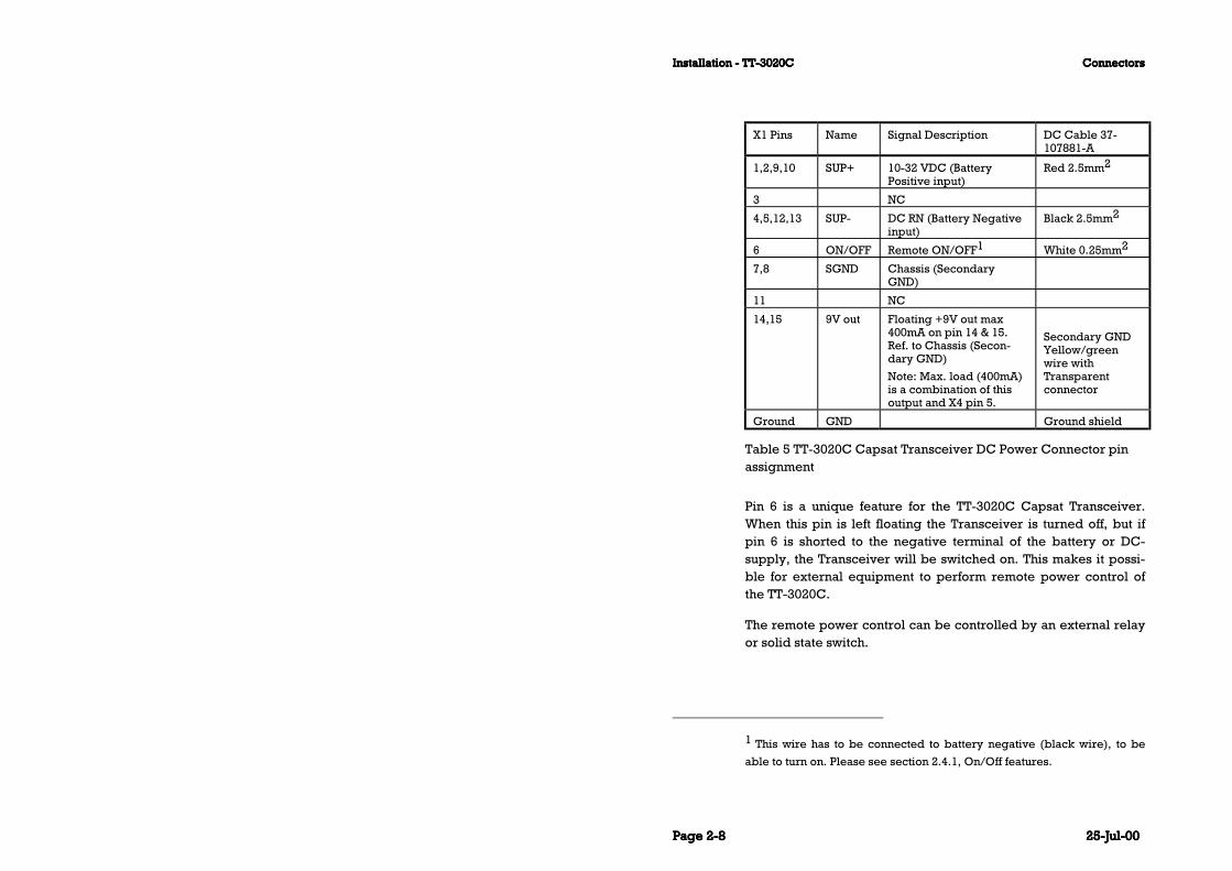
X1 Pins Name Signal Description DC Cable 37-107881-A
1,2,9,10 SUP+ 10-32 VDC (BatteryPositive input)
Red 2.5mm2
3 NC
4,5,12,13 SUP- DC RN (Battery Negativeinput)
Black 2.5mm2
6 ON/OFF Remote ON/OFF1 White 0.25mm2
7,8 SGND Chassis (SecondaryGND)
11 NC
14,15 9V out Floating +9V out max400mA on pin 14 & 15.Ref. to Chassis (Secon-dary GND)
Note: Max. load (400mA)is a combination of thisoutput and X4 pin 5.
Secondary GNDYellow/greenwire withTransparentconnector
Ground GND Ground shield
Table 5 TT-3020C Capsat Transceiver DC Power Connector pinassignment
Pin 6 is a unique feature for the TT-3020C Capsat Transceiver.When this pin is left floating the Transceiver is turned off, but ifpin 6 is shorted to the negative terminal of the battery or DC-supply, the Transceiver will be switched on. This makes it possi-ble for external equipment to perform remote power control ofthe TT-3020C.
The remote power control can be controlled by an external relayor solid state switch.
1 This wire has to be connected to battery negative (black wire), to be
able to turn on. Please see section 2.4.1, On/Off features.
ConnectorsConnectorsConnectorsConnectors Installation - TT-3020CInstallation - TT-3020CInstallation - TT-3020CInstallation - TT-3020C
25-Jul-0025-Jul-0025-Jul-0025-Jul-00 Page Page Page Page 2-92-92-92-9
The battery connection input is floating, i.e. there is no galvanicconnection from any of the battery poles to the cabinet frame.
2.5.2 DTE Communication port
The TT-3020C Capsat Transceiver communicates with a controllerdevice via the standard EIA/TIA-232E ports on a female 9 poleSub-D connector, located on the rear panel at X3.
2.5.2.1 Baudrate and protocol settings
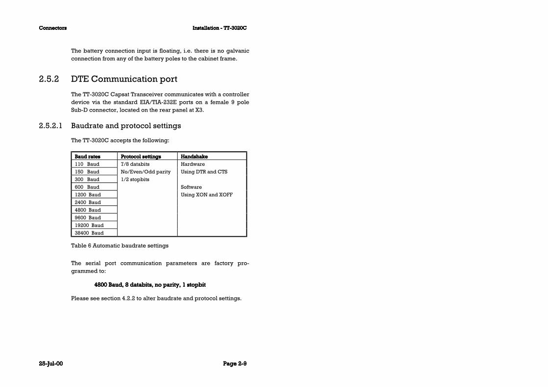
The TT-3020C accepts the following:
Baud ratesBaud ratesBaud ratesBaud rates Protocol settingsProtocol settingsProtocol settingsProtocol settings HandshakeHandshakeHandshakeHandshake
110 Baud 7/8 databits Hardware
150 Baud No/Even/Odd parity Using DTR and CTS
300 Baud 1/2 stopbits
600 Baud Software
1200 Baud Using XON and XOFF
2400 Baud
4800 Baud
9600 Baud
19200 Baud
38400 Baud
Table 6 Automatic baudrate settings
The serial port communication parameters are factory pro-grammed to:
4800 Baud, 8 databits, no parity, 1 stopbit4800 Baud, 8 databits, no parity, 1 stopbit4800 Baud, 8 databits, no parity, 1 stopbit4800 Baud, 8 databits, no parity, 1 stopbit
Please see section 4.2.2 to alter baudrate and protocol settings.

Installation - TT-3020CInstallation - TT-3020CInstallation - TT-3020CInstallation - TT-3020C ConnectorsConnectorsConnectorsConnectors
Page Page Page Page 2-102-102-102-10 25-Jul-0025-Jul-0025-Jul-0025-Jul-00
2.5.2.2 DTE Connector interface
The TT-3020C which is a DCE uses the signals listed in Table 7(marked with a in the Used column).Please notice that DTE pinnaming is used.
NameNameNameName Signal descriptionSignal descriptionSignal descriptionSignal description 9-Pin9-Pin9-Pin9-Pin UsedUsedUsedUsed LevelsLevelsLevelsLevels DirectionDirectionDirectionDirection
DCD Data Carrier Detect 1 EIA/TIA-232-E
RxD Received Data 2 EIA/TIA-232-E
TxD Transmitted Data 3 EIA/TIA-232-E
DTR Data Terminal Ready 4 EIA/TIA-232-E
GND Ground 5
DSR Data Set Ready 6 EIA/TIA-232-E
RTS Request To Send 7
CTS Clear To Send 8 EIA/TIA-232-E
RI1 Ring Indicator 9 EIA/TIA-232-E
Table 7 TT-3020C X3 pin assignment
The symbol means that the signal is generated by the Trans-ceiver.
For full operating specifications for the serial interface, you arekindly requested to refer to the CCITT Rec. V24 and the EIA/TIA-232-E specifications.
2.5.2.3 Interfacing to peripherals
To Interface the TT-3020C to a TT-3606E Message Terminal, sim-ply use the communication cable enclosed in the delivery.
1 The RI indicator goes high (approximately 8 Volts), when a message or
an EGC is received. RI is reset to low when the message/EGC has been
printed and/or routed to external printer/DTE equipment.

ConnectorsConnectorsConnectorsConnectors Installation - TT-3020CInstallation - TT-3020CInstallation - TT-3020CInstallation - TT-3020C
25-Jul-0025-Jul-0025-Jul-0025-Jul-00 Page Page Page Page 2-112-112-112-11
An extended serial communication cable should not exceed 100meters as the TT-3606E works on 4800 Baud using the EIA-423standard.
The TT-3020C optionally uses either hardware or software flowcontrol.
Hardware flow control is accomplished by using the DTR and CTSsignals.
Software flow control is accomplished by connecting the DTR andCTS, allowing both TT-3020C and the peripheral to control dataflow by means XON XOFF. ENQ/ACK cannot be used.
2.5.3 I/O Connector
The I/O connector X4X4X4X4 on the back panel of the TT-3020C Trans-ceiver can be used for
ArcNet 156Kbit communication to control the TT-3042D Re-mote Alarm Distress Box with additional printer or the TT-3608G Printer Unit.
The International NMEA 0183 version 2.1 communicationstandard input and output when connecting to a commercialavailable navigator device or using the built-in GPS in navi-gation mode.
Four parallel In/Out RS-410N pins and two RS-410N input pinsto control the TT-3042C Remote Alarm/Distress box.

Installation - TT-3020CInstallation - TT-3020CInstallation - TT-3020CInstallation - TT-3020C ConnectorsConnectorsConnectorsConnectors
Page Page Page Page 2-122-122-122-12 25-Jul-0025-Jul-0025-Jul-0025-Jul-00
Signal X4 pin Specification general purpose I/O
I/O0 (IO) 1 Digital open collector output with pull-
up/input with pull-up (RS-410N).
I/O1 (IO) 2 Digital open collector output with pull-
up/input with pull-up (RS-410N).
I/O2 (IO) 3 Digital open collector output with pull-
up/input with pull-up (RS-410N).
I/O3 (IO) 4 Digital open collector output with pull-
up/input with pull-up (RS-410N).
9Vdc (O) 5 DC +9V, ±10%. Max. 400mA. Floating
Supply voltage for external devices.
Note: Max. load (400mA) is a combina-
tion of this output and X1 pin 14,15.
Ground 6,9 Ground reference.
ArcNet A/B (IO) 7/8 ArcNet signal wires A/B (ATA/ANSI
878.1; ARCNET/TB).
NMEA Out A/B 10/11 NMEA 0183 output signal wires A/B
(NMEA 0183 version 2.1).
NMEA In A/B 12/13 NMEA 0183 input signal wires A/B
(NMEA 0183 version 2.1).
I4 (I) 14 Digital input with pull-up (RS-410N).
I5 (I) 15 Digital input with pull-up (RS-410N).
Table 8 TT-3020C X4 pin assignment
The I/O connector, a standard DB-15 female connector, is locatedon the rear panel of the transceiver and is marked X4.
2.5.3.1 NMEA 0183 Reception
The NMEA 0183 Standard uses the ASCII alphabet to send stringscontaining navigational data. This data can be read by the Trans-ceiver via the I/O NMEA interface connector X4.
The following is a list of the NMEA codes that the Transceiver willrecognise with or without a built-in GPS.

ConnectorsConnectorsConnectorsConnectors Installation - TT-3020CInstallation - TT-3020CInstallation - TT-3020CInstallation - TT-3020C
25-Jul-0025-Jul-0025-Jul-0025-Jul-00 Page Page Page Page 2-132-132-132-13
VHWHeading and speed information
XDRTransducer measurements
MWVWind speed and angle
MTWWater temperature
The following is a list of the NMEA codes that the Transceiver willrecognise, if you do not have a built-in GPS or the built-in GPS isin acquisition mode.
GGAGlobal position data. If the NMEA 0183 GGA string re-ceived by the transceiver has an empty field the positioninformation will not be updated.
GLLGeographic position, latitude and longitude. If the NMEA0183 GLL string received by the transceiver has an emptyfield the position information will not be updated.
VTGHeading (track) and speed information.
HDTHeading information.
2.5.3.2 NMEA 0183 Navigational Interface
A large number of Navigators will provide suitable NMEA 0183strings to the Capsat Transceiver.

Installation - TT-3020CInstallation - TT-3020CInstallation - TT-3020CInstallation - TT-3020C ConnectorsConnectorsConnectorsConnectors
Page Page Page Page 2-142-142-142-14 25-Jul-0025-Jul-0025-Jul-0025-Jul-00
2.5.3.3 NMEA 0183 Transmission
When your Transceiver has a built-in GPS, it sends out NMEA0183 navigational data to the device connected to the Trans-ceiver, via the I/O NMEA connector X4.
The following four strings:
VTG Heading and speed informationGLL Geographic position, latitude and longitudeGGAGlobal Positioning System fix data (includes time of position)ZDA Time and date
are sent out when the Transceiver/GPS is in navigation mode. Thetime in the position strings and the Time-and-date string are al-ways the same. The spacing between each block of data is 2 sec-onds and 0.5 seconds between GLL, GGA and ZDA strings whenthey are present.
An example is:$GPVTG,000.,T,000.,M,00.0,N,00.0,K
$GPGLL,5544.44,N,01228.64,E,121003,A
$GPGGA,121003,5544.44,N,01228.64,E,1,04,1,37,M,,M,,
$GPZDA,121003,19,02,1993,,
The following three strings: VTG, GLL and GGA are sent out whenthe Transceiver/GPS is in acquisition mode and the currentlystored position is less than 24 hours old. The time indicates thatof the last known position. The course and speed are 8 secondmean values.
An example is:$GPVTG,180.,T,180.,M,01.0,N,00.0,K
$GPGLL,5544.45,N,01228.67,E,121059,
$GPGGA,121059,5544.45,N,01228.67,E,0,00,1,23,M,,M,,
The following three strings: VTG, GLL and GGA are sent out whenthe Transceiver/GPS is in acquisition mode and the currently
ConnectorsConnectorsConnectorsConnectors Installation - TT-3020CInstallation - TT-3020CInstallation - TT-3020CInstallation - TT-3020C
25-Jul-0025-Jul-0025-Jul-0025-Jul-00 Page Page Page Page 2-152-152-152-15
stored position is more than 24 hours old. The time field is empty.The course and speed are 8 second mean values.
An example is:$GPVTG,139.,T,139.,M,02.0,N,00.0,K
$GPGLL,5544.45,N,01228.68,E,,
$GPGGA,,5544.45,N,01228.68,E,0,00,1,0,M,,M,,
An empty GLL string is sent out when there is no built-in GPS orbefore the GPS module has been started by the Transceiver.$GPGLL,,,,,,
$GPGLL,,,,,,
$GPGLL,,,,,,
2.5.4 Printer port
The printer port connector X5 is located on the rear panel.
This parallel interface conforms to the standard Centronics inter-face used e.g. on IBM compatible PC's.

Installation - TT-3020CInstallation - TT-3020CInstallation - TT-3020CInstallation - TT-3020C ConnectorsConnectorsConnectorsConnectors
Page Page Page Page 2-162-162-162-16 25-Jul-0025-Jul-0025-Jul-0025-Jul-00
Pin Name Signal Description
1 STRB Strobe
2 DAT0 Data Bit 0
3 DAT1 Data Bit 1
4 DAT2 Data Bit 2
5 DAT3 Data Bit 3
6 DAT4 Data Bit 4
7 DAT5 Data Bit 5
8 DAT6 Data Bit 6
9 DAT7 Data Bit 7
10 ACKN Acknowledge
11 BUSY Printer Busy
12 PE Paper End (out of paper)
13 SEL Printer Selected
14 ALFD Auto Line Feed
15 ERR Printer Error
16 INIT Initialise Printer
17 SLCT Select Printer
18 GND Ground
19 GND Ground
20 GND Ground
21 GND Ground
22 GND Ground
23 GND Ground
24 GND Ground
25 GND Ground
Table 9 Printer port (X5) pin assignment
Built-in GPS (optional)Built-in GPS (optional)Built-in GPS (optional)Built-in GPS (optional) Installation - TT-3020CInstallation - TT-3020CInstallation - TT-3020CInstallation - TT-3020C
25-Jul-0025-Jul-0025-Jul-0025-Jul-00 Page Page Page Page 2-172-172-172-17
2.5.5 Grounding
RF-grounding of an Integrated Capsat System requires specialattention. Each unit shall have its own individual low-inductanceearth connection. The use of a common bus bar for grounding isnot recommended as this can lead to unwanted common-modecoupling effects. The ground should be connected to the cabinetsmetal frame to provide a return path for fault currents due toequipment malfunction or external faults such as lightning. Inter-connecting cables must be well screened.
2.6 Built-in GPS (optional)GPS means Global Positioning System.
The GPS module is installed from the factory and you need not toperform any installation to use it.
If you have ordered your Capsat Transceiver without a built-inGPS and you later need to install a GPS module, then you shouldcontact your dealer to obtain instructions on how to accomplishthis.

Installation - TT-3020CInstallation - TT-3020CInstallation - TT-3020CInstallation - TT-3020C Mounting bracketMounting bracketMounting bracketMounting bracket
Page Page Page Page 2-182-182-182-18 25-Jul-0025-Jul-0025-Jul-0025-Jul-00
2.6.1 GPS specifications
The GPS receiver module tracks 12 GPS satellites . The followingpower-up time estimates are available, from field test.
Start state GPS 25
All data known 15 sec
Position, time and almanac known 45 sec
Almanac known 90 sec
No data known 5 min
Field test cold start same position
after 8 hours off
Update rate 1 second (typical)
Position accuracy 15m RMS (100m with
Selective Availability on)
Typical velocity accuracy 0.2m/s RMS
Table 10 GPS Specifications
2.7 Mounting bracketThe TT-3020C Capsat Transceiver is supplied with an universalmounting plate (41-107093-A) which allows mounting to e.g. a ta-ble.

Mounting bracketMounting bracketMounting bracketMounting bracket Installation - TT-3020CInstallation - TT-3020CInstallation - TT-3020CInstallation - TT-3020C
25-Jul-0025-Jul-0025-Jul-0025-Jul-00 Page Page Page Page 2-192-192-192-19
Figure 3 TT-3020C Capsat Transceiver mounting plate.
All dimensions are in mm
Figure 4 Front panel of the TT-3020C Capsat Transceiver withmounting bracket
All dimensions are in mm

Installation - TT-3020CInstallation - TT-3020CInstallation - TT-3020CInstallation - TT-3020C Mounting bracketMounting bracketMounting bracketMounting bracket
Page Page Page Page 2-202-202-202-20 25-Jul-0025-Jul-0025-Jul-0025-Jul-00
It is recommended that the Transceiver is mounted in an open airlocation.

Power requirementsPower requirementsPower requirementsPower requirements System InstallationSystem InstallationSystem InstallationSystem Installation
25-Jul-0025-Jul-0025-Jul-0025-Jul-00 Page Page Page Page 3-13-13-13-1
3 System Installation
This chapter provides specific information enabling you to installthe TT-3020C Maritime Capsat system with a minimal effort. Thedefault, or factory configuration is described, together with pro-cedures for altering this configuration.
The TT-3000C Integrated Capsat system consists of the followingcomponents:
TT-3020C Inmarsat-C Maritime Transceiver with GPSoption.
TT-3001B Opt. 001 Maritime Antenna Unit orTT-3005A Maritime Antenna Unit. orTT-3005M Maritime Antenna UnitTT-3606E Message Terminal TT-3601E Keyboard TT-3680B Power SupplyTT-3608A Hard Copy Printer orTT-3042D Local PrinterTT-3042C (optional) Remote Alarm Distress BoxTT-3042D (optional) Remote Alarm Distress Box with PrinterTT-3608G (optional) Remote Printer Unit
3.1 Power requirementsA TT-3000C Integrated Capsat System operates on either 115VAC, 220 VAC or a 24 V floating DC (nominal value), with an ab-solute minimum of 15 V DC at the input terminal of the TT-3680BAC/DC converter. The TT-3680B provides automatic switch overto the DC supply in case a drop out occurs on the mains.
The total power consumption varies with the particular system inquestion. As a guide-line, please note the power consumption ofthe following equipment:

System InstallationSystem InstallationSystem InstallationSystem Installation Power requirementsPower requirementsPower requirementsPower requirements
Page Page Page Page 3-23-23-23-2 25-Jul-0025-Jul-0025-Jul-0025-Jul-00
Power requirements Receivemode
Transmitmode
TT-3020C Capsat Transceiver incl. TT-3005Mantenna.Floating DC (10-32V).
3.8W 80WMax.90W
TT-3020C Capsat Transceiver Incl. TT-3005MAntenna & GPS. Floating DC (10-32V).
4.4W 80WMax.90W
TT-3606E Message Terminal, incl. Keyboard.Floating DC (10.5 - 32V)
13 Waverage
20 Wpeak
TT-3608A Printer 220AC or option 010 DCsupply floating (10.5 - 32V)
33W
TT-3042D Remote Alarm Distress Box withprinter
2.5 Wstandby
7 Wprinting
TT-3608G Remote Printer Unit 2.5 Wstandby
7 Wprinting
Table 11 Capsat System component power requirements
3.1.1 Fuses
In case you experience that a fuse needs replacement, pleasecheck that the equipment has not been exposed to physical dam-age before fuse replacement takes place.
WARNINGWARNINGWARNINGWARNING
To avoid hazardous electrical shock, do not perform electricaltests if there is any sign of shipping damage to any portion of
the front or rear panel or the outer cover. Read the safetysummary at the front of this manual before installing or
operating the TT-3020C Transceiver
Compass Safe DistanceCompass Safe DistanceCompass Safe DistanceCompass Safe Distance System InstallationSystem InstallationSystem InstallationSystem Installation
25-Jul-0025-Jul-0025-Jul-0025-Jul-00 Page Page Page Page 3-33-33-33-3
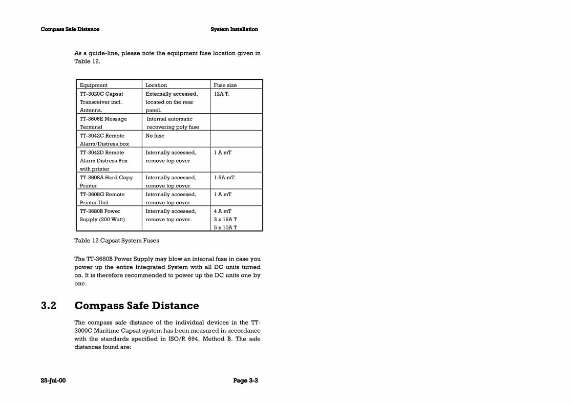
As a guide-line, please note the equipment fuse location given inTable 12.
Equipment Location Fuse size
TT-3020C Capsat
Transceiver incl.
Antenna.
Externally accessed,
located on the rear
panel.
12A T.
TT-3606E Message
Terminal
Internal automatic
recovering poly fuse
TT-3042C Remote
Alarm/Distress box
No fuse
TT-3042D Remote
Alarm Distress Box
with printer
Internally accessed,
remove top cover
1 A mT
TT-3608A Hard Copy
Printer
Internally accessed,
remove top cover
1.5A mT.
TT-3608G Remote
Printer Unit
Internally accessed,
remove top cover
1 A mT
TT-3680B Power
Supply (200 Watt)
Internally accessed,
remove top cover.
4 A mT
3 x 16A T
5 x 10A T
Table 12 Capsat System Fuses
The TT-3680B Power Supply may blow an internal fuse in case youpower up the entire Integrated System with all DC units turnedon. It is therefore recommended to power up the DC units one byone.
3.2 Compass Safe DistanceThe compass safe distance of the individual devices in the TT-3000C Maritime Capsat system has been measured in accordancewith the standards specified in ISO/R 694, Method B. The safedistances found are:

System InstallationSystem InstallationSystem InstallationSystem Installation Compass Safe DistanceCompass Safe DistanceCompass Safe DistanceCompass Safe Distance
Page Page Page Page 3-43-43-43-4 25-Jul-0025-Jul-0025-Jul-0025-Jul-00
Model Compass Safe Distance
TT-3020C, Transceiver 0.5 m
TT-3606E Message Terminal 0.5 m
TT-3601E Keyboard 0.3 m
TT-3042C, Remote Alarm DistressBox
0.5 m
TT-3601A, Keyboard 0.5 m
TT-3608A, Hard copy printer 2.0 m
TT-3680B, Power supply 2.0 m
TT-3005M Maritime Antenna 0.3 m
Table 13 Compass Safe Distance
AntennasAntennasAntennasAntennas System InstallationSystem InstallationSystem InstallationSystem Installation
25-Jul-0025-Jul-0025-Jul-0025-Jul-00 Page Page Page Page 3-53-53-53-5
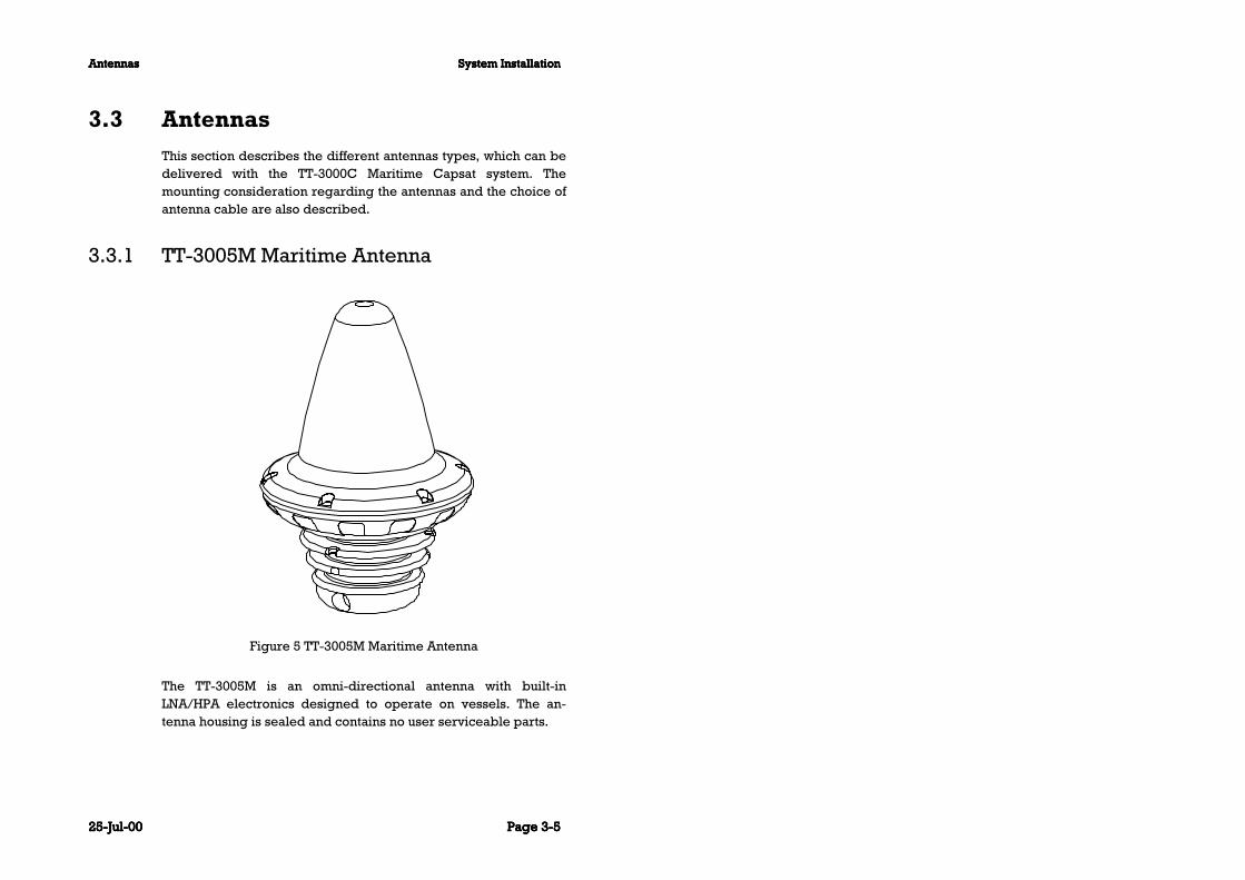
3.3 AntennasThis section describes the different antennas types, which can bedelivered with the TT-3000C Maritime Capsat system. Themounting consideration regarding the antennas and the choice ofantenna cable are also described.
3.3.1 TT-3005M Maritime Antenna
Figure 5 TT-3005M Maritime Antenna
The TT-3005M is an omni-directional antenna with built-inLNA/HPA electronics designed to operate on vessels. The an-tenna housing is sealed and contains no user serviceable parts.

System InstallationSystem InstallationSystem InstallationSystem Installation AntennasAntennasAntennasAntennas
Page Page Page Page 3-63-63-63-6 25-Jul-0025-Jul-0025-Jul-0025-Jul-00
The antenna is very compact and is designed to operate in a cor-rosive environment and in extreme weather conditions withoutany service. It has a modular construction that allows easy ex-change of antenna elements.
The antenna is designed to work with the Capsat transceivers TT-3020C, TT-3022D and TT-3022C.
The TT-3005M antenna is fully compatible with the Inmarsat-CGMDSS (General Maritime Distress and Safety System) specifica-tions, , and can also receive GPS signals while not transmitting.This antenna can handle up to 32 Kbytes transmission length andup to 100 meter coax cable.
The TT-3005M antenna is designed to operate when the satelliteis visible over the horizon and no signal path blockage is present.
The TT-3005M antenna is equipped with a TNC female connectorand with 1’’ tube mounting. Please see section 3.3.4.

AntennasAntennasAntennasAntennas System InstallationSystem InstallationSystem InstallationSystem Installation
25-Jul-0025-Jul-0025-Jul-0025-Jul-00 Page Page Page Page 3-73-73-73-7
TT-3005M
Maritime Antenna
Inmarsat-C/GPS omnidirectional
antenna, RHC polarised.
G/T: -23 dB/K at 5° elevation
EIRP: 14 dBW ± 2dB at 5° elevation.
Temperature: -35°C to 55°C operating,
-40°C to 80°C storage.
Dimensions (H x D): 178 mm x 122 mm.
Weight: 0.90 kg.
Maximum transmission
length
32 Kbyte.
Solar Radiation Max. flux density 1200W/m2.
Relative Humidity 95% non-condensing at 40°C.
Precipitation Up to 100 mm/hour, droplet size 0.5 to
4.5 mm
Ice Up to 25 mm.
Wind Up to 200 km/hour.
Vibration Operational Random 5-20 Hz: 0.005 g2/Hz
20-150 Hz: -3dB/oct. (0.5g RMS).
Vibration Survival Random 5-20 Hz: 0.05 g2/Hz
20-150 Hz: -3dB/oct. (1.7g RMS).
Shock Half sine 20g/11ms
Antenna Mounting 1” tube mounting
Transceiver coax cable 0.7Ohm max DC resistance (shield +
inner conductor)
17dB max RF insertion loss at 1.6GHz.
100 meter max cable length. TNC
connectors.
Table 14 TT-3005M technical specifications.
3.3.1.1 Antenna connector
"N" and ‘’TNC’’ type connectors are available from manufacturerslike:
Suhner, Radial, Omnispectra, Kings, etc.

System InstallationSystem InstallationSystem InstallationSystem Installation AntennasAntennasAntennasAntennas
Page Page Page Page 3-83-83-83-8 25-Jul-0025-Jul-0025-Jul-0025-Jul-00
3.3.1.2 Antenna cable
The TT-3005M Antenna specifications requires that the totalmaximal attenuation at 1.65 GHz must be less than 17 dB, and themaximal total (short-circuited in one end) DC resistance must notexceed 0.7 Ohms.
In case the antenna cable is to be produced on site, the cabletype should match the below listed guidelines:
Range (m)Range (m)Range (m)Range (m) Cable type no.Cable type no.Cable type no.Cable type no. Connector type no. (Suhners)Connector type no. (Suhners)Connector type no. (Suhners)Connector type no. (Suhners)
1 - 10 RG-223U, 5.5 mm 11TNC-50-3-14c and 11N-50-
3-29c
11 - 40 RG-214U, 10.8 mm 11TNC-50-7-2c and 11N-50-7-
44c
41 - 80 Suhner:
SA7272, 10.0 mm
Nokia:
02Y(st)C2YC 2,7/7,3AF
The SA7272 cable with N
connectors (11N-50-7-35) and
one adapters N female to
TNC male (33TNC-N-50-51)
TNC male / N male
81 - 100 SA12272, 15.0 mm The SA12272 cable with N
connectors (11N-50-12-35C)
and one adapter N female to
TNC male (33TNC-N-50-51)
Table 15 TT-3020C Capsat Transceiver Antenna Cable types(TNC - TNC) for TT-3005M.
All antenna cables types are double shielded.
The antenna cable may run together with radar or navigator ca-bles. Separate cable ditch is not required.
If you install your system in a permanent location, we recommendthat you, after the installation of the antenna, wrap the connector

AntennasAntennasAntennasAntennas System InstallationSystem InstallationSystem InstallationSystem Installation
25-Jul-0025-Jul-0025-Jul-0025-Jul-00 Page Page Page Page 3-93-93-93-9
with the enclosed self-bonding tape, disabling water from pene-trating the connection.
3.3.1.3 Mounting
The TT-3005M maritime antenna is constructed for 1” tubemounting.
Figure 6 TT-3005M 1’’ Tube Mounting
It is important to notice that the pole mount device has to be dis-connected from the antenna body when the antenna cable shouldbe mounted. It is not possible to mount the cable without disman-tling the pole mount.
System InstallationSystem InstallationSystem InstallationSystem Installation AntennasAntennasAntennasAntennas
Page Page Page Page 3-103-103-103-10 25-Jul-0025-Jul-0025-Jul-0025-Jul-00
3.3.1.4 Transceiver Configuration
This new antenna is designed to use a very low amount of power.To ensure that the transceiver detects the antenna as connectedthe voltage output of the transceiver has to be reduced. Issuingthe following command in the transceiver shell does this:
“Se —f 0”
If this command is not run the transceiver will probably set-up awarning box stating that the antenna is not connected.
Please refer to section 4.2.3 for a detailed description.
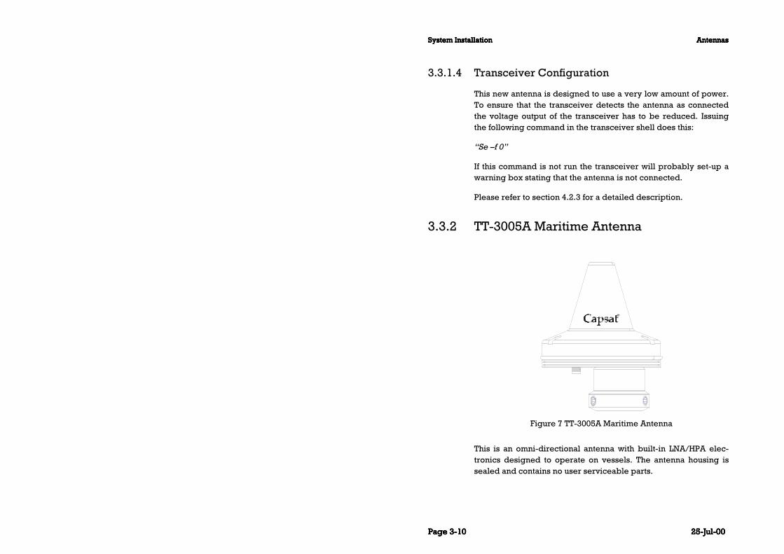
3.3.2 TT-3005A Maritime Antenna
Figure 7 TT-3005A Maritime Antenna
This is an omni-directional antenna with built-in LNA/HPA elec-tronics designed to operate on vessels. The antenna housing issealed and contains no user serviceable parts.

AntennasAntennasAntennasAntennas System InstallationSystem InstallationSystem InstallationSystem Installation
25-Jul-0025-Jul-0025-Jul-0025-Jul-00 Page Page Page Page 3-113-113-113-11
The antenna is very compact and is designed to operate in a cor-rosive environment and in extreme weather conditions withoutany service. It has a modular construction that allows easy ex-change of antenna elements.
The TT-3005A antenna is fully compatible with the Inmarsat-CGMDSS (General Maritime Distress and Safety System) specifica-tions, , and can also receive GPS signals while not transmitting.This antenna can handle up to 10Kbyte transmission length andup to 70 meter coax cable.
The TT-3005A antenna is designed to operate when the satellite isvisible over the horizon and no signal path blockage is present.
The TT-3005A antenna is equipped with a TNC female connectorand with 1.5’’ tube mounting. Please see section 3.3.4.

System InstallationSystem InstallationSystem InstallationSystem Installation AntennasAntennasAntennasAntennas
Page Page Page Page 3-123-123-123-12 25-Jul-0025-Jul-0025-Jul-0025-Jul-00
TT-3005A
Maritime Antenna
Inmarsat-C/GPS omnidirectional
antenna, RHC polarised.
G/T: -23 dB/K at 5° elevation
EIRP: 14 dBW ± 2dB at 5° elevation.
Temperature: -35°C to 55°C operating,
-40°C to 80°C storage.
Dimensions (H x G): 120 mm x 146 mm
conical excl. gasket. Weight: 0.75 kg.
Maximum transmission
length
10 Kbyte, depending on wind tempera-
ture.
Solar Radiation Max. flux density 1200W/m2.
Relative Humidity 95% non-condensing at 40°C.
Precipitation Up to 50 mm/hour, droplet size 0.5 to
4.5 mm
Ice Up to 25 mm.
Wind Up to 200 km/hour.
Vibration Operational Random 5-20 Hz: 0.02 g2/Hz
20-150 Hz: -3dB/oct. (1.0g RMS).
Vibration Survival Random 5-20 Hz: 0.05 g2/Hz
20-150 Hz: -3dB/oct. (1.7g RMS).
Shock Half sine 20g/11ms
Antenna Mounting 1.5” tube
Transceiver coax cable 0.7Ohm max DC resistance (shield +
inner conductor)
10dB max RF insertion loss at 1.6GHz.
70 meter max cable length. TNC
connectors.
Table 16 TT-3005A technical specifications.
3.3.2.1 Antenna connector
"N" and ‘’TNC’’ type connectors are available from manufacturerslike:
Suhner, Radial, Omnispectra, Kings, etc.

AntennasAntennasAntennasAntennas System InstallationSystem InstallationSystem InstallationSystem Installation
25-Jul-0025-Jul-0025-Jul-0025-Jul-00 Page Page Page Page 3-133-133-133-13
3.3.2.2 Antenna cable
The TT-3005A Antenna specifications requires that the totalmaximal attenuation at 1.65 GHz must be less than 10 dB, and themaximal total (short-circuited in one end) DC resistance must notexceed 0.7 Ohms.
In case the antenna cable is to be produced on site, the cabletype should match the below listed guide-lines:
Range (m)Range (m)Range (m)Range (m) Cable type no.Cable type no.Cable type no.Cable type no. Connector type no. (Suhners)Connector type no. (Suhners)Connector type no. (Suhners)Connector type no. (Suhners)
1 - 10 RG-223U, 5.5 mm 11TNC-50-3-14c
11 - 25 RG-214U, 10.8 mm 11TNC-50-7-2c
26 - 50 Suhner:
SA7272, 10.0 mm
Nokia:
02Y(st)C2YC 2,7/7,3AF
The SA7272 cable with N
connectors (11N-50-7-35) and
two adapters N female to TNC
male (33TNC-N-50-51)
TNC male / TNC male
51 - 70 SA12272, 15.0 mm The SA12272 cable with N
connectors (11N-50-12-35C)
and two adapters N female to
TNC male (33TNC-N-50-51)
Table 17 TT-3020C Capsat Transceiver Antenna Cable types(TNC - TNC) for TT-3005A antenna.
All antenna cables are double shielded.
The antenna cable may run together with radar or navigator ca-bles. Separate cable ditch is not required.
If you install your system in a permanent location, we recommendthat you, after the installation of the antenna, wrap the connectorwith the enclosed self-bonding tape, disabling water from pene-trating the connection.

System InstallationSystem InstallationSystem InstallationSystem Installation AntennasAntennasAntennasAntennas
Page Page Page Page 3-143-143-143-14 25-Jul-0025-Jul-0025-Jul-0025-Jul-00
3.3.2.3 Mounting
The TT-3005A maritime antenna is constructed for 1.5” tubemounting.
Figure 8 TT-3005A 1.5’’ tube mounting
3.3.2.4 Low antenna power in Rx mode
The TT-3005A Antenna Rx power can be reduced from 1.1W with(14V) to 0.7W with (9V).
For information on how to reduce the antenna power, please referto section 4.2.3.

AntennasAntennasAntennasAntennas System InstallationSystem InstallationSystem InstallationSystem Installation
25-Jul-0025-Jul-0025-Jul-0025-Jul-00 Page Page Page Page 3-153-153-153-15
3.3.3 TT-3001B Maritime Antenna
Figure 9 TT-3001B opt. 001 Maritime Antenna
This is an omni-directional antenna with built-in LNA/HPA elec-tronics designed to operate on vessels. The antenna housing issealed and contains no user serviceable parts.
The antenna is very compact and is designed to operate in a cor-rosive environment and in extreme weather conditions withoutany service. It has a modular construction that allows easy ex-change of antenna elements. The antenna housing is sealed withtamper-resistant TORX screws, so that it can only be disassem-bled by Thrane & Thrane approved technicians.
The antenna is fully compatible with the Inmarsat-C GMDSS(General Maritime Distress and Safety System) specifications, andcan also receive GPS signals while not transmitting and operatewith up to 100 meter antenna cable.
The TT-3001B opt. 001 antenna is equipped with a N female con-nector and constructed for 1.5’’ tube mounting. Please see section3.3.4.

System InstallationSystem InstallationSystem InstallationSystem Installation AntennasAntennasAntennasAntennas
Page Page Page Page 3-163-163-163-16 25-Jul-0025-Jul-0025-Jul-0025-Jul-00
TT-3001B Opt. 001
Maritime Antenna
Inmarsat-C/GPS omnidirectional
antenna, RHC polarised.
G/T: -23 dB/K
EIRP: 14 dBW ± 2dB at 5° elevation.
Temperature: -35°C to 55°C
operating,
-40°C to 80°C storage.
Dimensions (H x G): 237 mm x 150
mm conical ex. mounting.
Weight 2.2 Kg.
Maximum transmission
length
32 Kbyte, which is Inmarsat
maximum
Solar Radiation Infra-red radiation 500W/m2 (EME).
Relative Humidity 95% non-condensing at 40°C.
Precipitation Up to 50 mm/hour, droplet size 0.5 to
4.5 mm (EME).
Ice Up to 25 mm (EME).
Wind Up to 200 km/hour
Vibration Operational Random 5-20 Hz: 0.02 g2/Hz
20-150 Hz: -3dB/oct. (1.0g RMS).
Vibration Survival Random 5-20 Hz: 0.05 g2/Hz
20-150 Hz: -3dB/oct. (1.7g RMS).
Shock Half sine 20g/11ms
Antenna Mounting (Maritime) Standard 1.5" tube mounting.
Table 18 TT-3001B opt. 001 Technical Specifications
3.3.3.1 Antenna connector
"N" and ‘’TNC’’ type connectors are available from manufacturerslike:
Suhner, Radial, Omnispectra, Kings, etc.

AntennasAntennasAntennasAntennas System InstallationSystem InstallationSystem InstallationSystem Installation
25-Jul-0025-Jul-0025-Jul-0025-Jul-00 Page Page Page Page 3-173-173-173-17
3.3.3.2 Antenna cable
If you are using the TT-3020C Transceiver with a TT-3001B opt.001 antenna with N connector, use cable with N and TNC con-nectors. The specification of this antenna requires that the totalmaximum attenuation at 1.65 GHz must be less than 16 dB, andthe maximal total (short-circuited in one end) DC resistance mustnot exceed 0.7 Ohms.
In case the antenna cable is to be produced on site, the cabletype should match the below listed guide-lines:
Range (m)Range (m)Range (m)Range (m) Cable type no.Cable type no.Cable type no.Cable type no. Connector type no. (Suhners)Connector type no. (Suhners)Connector type no. (Suhners)Connector type no. (Suhners)
1 - 10 RG-223U, 5.5 mm 11TNC-50-3-14c and 11N-50-
3-29c
11 - 40 RG-214U, 10.8 mm 11TNC-50-7-2c and 11N-50-7-
44c
41 - 80 Suhner:
SA7272, 10.0 mm
Nokia:
02Y(st)C2YC 2,7/7,3AF
The SA7272 cable with N
connectors (11N-50-7-35) and
one adapters N female to
TNC male (33TNC-N-50-51)
TNC male / N male
81 - 100 SA12272, 15.0 mm The SA12272 cable with N
connectors (11N-50-12-35C)
and one adapter N female to
TNC male (33TNC-N-50-51)
Table 19 TT-3020C Capsat Transceiver Antenna Cable types (N -TNC) for TT-3001B opt. 001.
All antenna cables types are double shielded.
The antenna cable may run together with radar or navigator ca-bles. Separate cable ditch is not required.

System InstallationSystem InstallationSystem InstallationSystem Installation AntennasAntennasAntennasAntennas
Page Page Page Page 3-183-183-183-18 25-Jul-0025-Jul-0025-Jul-0025-Jul-00
If you install your system in a permanent location, we recommendthat you, after the installation of the antenna, wrap the connectorwith the enclosed self-bonding tape, disabling water from pene-trating the connection.
3.3.3.3 Mounting
The TT-3001B opt. 001 maritime antenna is constructed for 1.5”tube mounting.
Capsat
Figure 10 TT-3001B-opt. 001 1.5’’ Tube mounting
3.3.4 Antenna Mounting Considerations
When installing the a Maritime Antenna you should find a locationon the vessel that is as free from obstructions as possible. Alsoyou should maintain a certain distance to other antennas, espe-cially radar installations. Normally the best place for the antennawould be above radar scanning antennas. The following safe dis-tances should be maintained:

AntennasAntennasAntennasAntennas System InstallationSystem InstallationSystem InstallationSystem Installation
25-Jul-0025-Jul-0025-Jul-0025-Jul-00 Page Page Page Page 3-193-193-193-19
Distance to HF antennas > 5 m
Distance to VHF antennas > 4 m
Distance to magnetic compass > 3 m
The antenna is designed to provide satellite coverage even whenthe vessel has pitch and roll movements up to 15°. To maintainthis coverage the antenna should be free from obstructions in thearea down to 15° below the horizon. Since this may not be possi-ble in the fore and aft directions of the vessel, the clear area canbe reduced to 5° below the horizon in the fore and aft directionsand 15° below the horizon in the port and starboard directions.Any compromise in this recommendation will degrade perform-ance.

System InstallationSystem InstallationSystem InstallationSystem Installation AntennasAntennasAntennasAntennas
Page Page Page Page 3-203-203-203-20 25-Jul-0025-Jul-0025-Jul-0025-Jul-00
15
Horizon
15
Horizon
Zenith
Obstructions should be below these
Figure 11 Inmarsat-C Antenna Mounting
If an obstruction such as a pole or a funnel is unavoidable, thefollowing guidelines apply:
According to IMO resolution 807 the distance to the obstructionshould be so large, that the obstruction only covers 2 degrees.This means that the safe distance is:
Safe distance = 29 * Diameter of obstruction
Example:
Obstruction is a 4" pole. Diameter = 0.1 m. Safe distance is29 * 0.1 m = 2.9 m

AntennasAntennasAntennasAntennas System InstallationSystem InstallationSystem InstallationSystem Installation
25-Jul-0025-Jul-0025-Jul-0025-Jul-00 Page Page Page Page 3-213-213-213-21
Max obstruction angle 2 degree
Figure 12 Inmarsat-C Antenna mounting near pole or funnel
3.3.5 Safety Distance for Antenna Units
The safety levels for the Thrane & Thrane INMARSAT-C AntennaUnits are based on the ANSI standard C95.1-1982 "American Na-tional Standard Safety Levels With Respect to Human Exposure toRadio Frequency Electromagnetic Fields, 300 kHz to 100 GHz"
This standard recommends the maximum power density at 1.6GHz exposed to human beings not to exceed 5 mW/cm².
At the maximum radiated output power from the INMARSAT-CAntenna (16 dBW EIRP) this corresponds to a minimum safetydistance of 30 cm.
In the standards from the European Telecommunication StandardInstitute (ETSI) concerning 1.5/1.6 GHz Satellite Earth Stations therecommendation will be maximum 8W/m² (0.8 mW/cm²). This

System InstallationSystem InstallationSystem InstallationSystem Installation AntennasAntennasAntennasAntennas
Page Page Page Page 3-223-223-223-22 25-Jul-0025-Jul-0025-Jul-0025-Jul-00
tighter recommendation correspond to a minimum safety dis-tance of 60 cm at 16 dBW.
To be sure that this distance is respected the Thrane & ThraneINMARSAT-C Antenna Units are provided with a label declaring aminimum safety distance on 2 feet (61 cm).
The relation between the power intensity are as follows:
Radiated intensity (W/m2) Distance (m)
10 0.56
25 0.36
100 0.18
Table 20 Radiated intensity

TT-3606E Message TerminalTT-3606E Message TerminalTT-3606E Message TerminalTT-3606E Message Terminal System InstallationSystem InstallationSystem InstallationSystem Installation
25-Jul-0025-Jul-0025-Jul-0025-Jul-00 Page Page Page Page 3-233-233-233-23
3.4 TT-3606E Message TerminalThe TT-3606E is a GMDSS approved Message Terminal for the TT-3020C Transceiver.
Figure 13 TT-3606E Message Terminal
In the following sections the interface to the 3606E Message Ter-minal are described.
Please be advised that a special Reference Manual for theTT-3606E Message Terminal is available.
3.4.1 Connectors
An illustration of the rear connectors is in Figure 14.

System InstallationSystem InstallationSystem InstallationSystem Installation TT-3606E Message TerminalTT-3606E Message TerminalTT-3606E Message TerminalTT-3606E Message Terminal
Page Page Page Page 3-243-243-243-24 25-Jul-0025-Jul-0025-Jul-0025-Jul-00
Figure 14 TT-3606E Rear Connectors
3.4.1.1 Power connector
The power input connector is a standard 15 pin SubD male con-nector, located on the rear panel of the TT-3606E and the pin as-signments are as indicated below. The Remote ON/OFF inputmakes it possible to place an eventual on/off switch at any loca-tion.
Pin Name Signal Description
1,2,9,10 + supply 10-32 VDC (Battery Positive input)
4,5,12,13 - supply DC Return (Battery Negative input)
6 Remote ON/OFF ON if connected to “- supply”
OFF if floating
7,8 SGND Chassis (Secondary GND)
Ground GND Shield
3,11,14,15 NC
Table 21 TT-3606E Power Connector
3.4.1.2 Communication port
The TT-3606E Message Terminal communicates with the TT-3020C Capsat Transceiver via one of the two standard RS-423ports, located on the rear panel.
The communication parameters are factory programmed to:
COM1, speed 4800 Baud, 8 databits, noCOM1, speed 4800 Baud, 8 databits, noCOM1, speed 4800 Baud, 8 databits, noCOM1, speed 4800 Baud, 8 databits, noparity, 1 stopbitparity, 1 stopbitparity, 1 stopbitparity, 1 stopbit
Alternatively these settings may be customer defined.

TT-3606E Message TerminalTT-3606E Message TerminalTT-3606E Message TerminalTT-3606E Message Terminal System InstallationSystem InstallationSystem InstallationSystem Installation
25-Jul-0025-Jul-0025-Jul-0025-Jul-00 Page Page Page Page 3-253-253-253-25
The CTS and DTR hardware handshake signals are used as de-fault.
The pin assignment for the two communication ports are identi-cal.
3.4.1.3 Printer port
The TT-3606E Message Terminal has a standard Centronicsprinter port. Please note that in the GMDSS system the TT-3608AHard Copy printer must be connected to the Transceiver.
The printer port connector is located on the rear panel.
3.4.2 TT-3601E keyboard
The TT-3601E Keyboard plugs into the Keyboard connector onthe rear panel of the TT-3606E. The keyboard connector is a stan-dard connector but please be aware that only the TT-3601E key-board is approved for GMDSS purposes.
Power: The keyboard is powered from TT-3606E MessageTerminal.
Grounding: TT-3601E Keyboard does normally not require anyseparate grounding.

System InstallationSystem InstallationSystem InstallationSystem Installation TT-3606E Message TerminalTT-3606E Message TerminalTT-3606E Message TerminalTT-3606E Message Terminal
Page Page Page Page 3-263-263-263-26 25-Jul-0025-Jul-0025-Jul-0025-Jul-00
3.4.3 Specifications
Processor 386SX-40MHz
RAM 4 MB
Flash DISK 2 MB
Display 10.4” Color TFT flatpanel, 640x480
Floppy drive 3.5”
Keyboard i/f 5-pin mini-DIN
Parallel printer port 25 pin SubD female connector
Serial port COM1 9 pin SubD male connector, DTE type
Serial port COM2 9 pin SubD male connector, DTE type
Environmental Meets or exceeds all INMARSAT specifica-
tions for the Inmarsat-C Network for SOLAS
with distress call functions. (CN114 and IEC
945 requirements). Meets CE-marking
(1997) requirements. Wheel Mark approved
Power Source 10 to 32 V floating DC, 15 pin SubD female
Power Consumption App. 20 Watts, maximum
App. 13 Watts, typical
Fuse Internal automatic recovering poly fuse
Ambient Temperature -20°C to 55°C operating
-40°C to 80°C storage.
Compass safe distance 50 cm
(measured in accordance with the standards
specified in ISO/R 694, Method B)
Dimensions H x W x D 221x 297 x 114.5 mm w/o bracket
256 x 297 x 114.5 mm w bracket at vertical
position
Weight 3.1 kg (including mounting bracket)
Table 22 TT-3606E Message Terminal Specifications

TT-3606E Message TerminalTT-3606E Message TerminalTT-3606E Message TerminalTT-3606E Message Terminal System InstallationSystem InstallationSystem InstallationSystem Installation
25-Jul-0025-Jul-0025-Jul-0025-Jul-00 Page Page Page Page 3-273-273-273-27
3.4.4 Mounting
Figure 15 llustrates the dimension of the panel cut-out and posi-tion of mounting holes when mounting the TT-3606E MessageTerminal in a console.
Figure 15 Mounting holes for TT-3606E
Figure 16 illustrates the position of the mounting holes for themounting bracket.

System InstallationSystem InstallationSystem InstallationSystem Installation TT-3606E Message TerminalTT-3606E Message TerminalTT-3606E Message TerminalTT-3606E Message Terminal
Page Page Page Page 3-283-283-283-28 25-Jul-0025-Jul-0025-Jul-0025-Jul-00
Figure 16 TT-3606E Mounting Bracket

TT-3680B Power SupplyTT-3680B Power SupplyTT-3680B Power SupplyTT-3680B Power Supply System InstallationSystem InstallationSystem InstallationSystem Installation
25-Jul-0025-Jul-0025-Jul-0025-Jul-00 Page Page Page Page 3-293-293-293-29
3.5 TT-3680B Power SupplyThe TT-3680B Power Supply operates on either 115 VAC or 230VAC internally selectable. The maximum power supplied is 200W.
The TT-3680B Power Supply has a connection for emergencybatteries and offers automatic switch-over in case of a drop-out ofthe mains. In the TT-3000C GMDSS system the emergency volt-age must be 24 V floating DC (nominal value), with an absoluteminimum of 15 V DC at the input terminal of the TT-3680B AC/DCconverter.
Each of the five different DC outputs are separately fused. It istherefore recommended to distribute the load on the differentoutputs.
Due to the heat TT-3680B develops during operation it is recom-mended that this unit is mounted separately.
Separate installation manual for TT-3680B, is available.
Figure 17 TT-3680B - 200W power supply.
3.5.1 Mounting

System InstallationSystem InstallationSystem InstallationSystem Installation TT-3680B Power SupplyTT-3680B Power SupplyTT-3680B Power SupplyTT-3680B Power Supply
Page Page Page Page 3-303-303-303-30 25-Jul-0025-Jul-0025-Jul-0025-Jul-00
Figure 18 Mounting holes for TT-3680B

TT-3608A Hard Copy PrinterTT-3608A Hard Copy PrinterTT-3608A Hard Copy PrinterTT-3608A Hard Copy Printer System InstallationSystem InstallationSystem InstallationSystem Installation
25-Jul-0025-Jul-0025-Jul-0025-Jul-00 Page Page Page Page 3-313-313-313-31
3.6 TT-3608A Hard Copy Printer
Figure 19 TT-3608A Hard copy printer
Connecting the TT-3608A Hard Copy Printer to the Transceiveroffers the highest security for hard copies of incoming messageseven if the TT-3606E is turned off.
The Integrated Capsat System is designed to allow the operatorto guide incoming messages to the TT-3608A Hard Copy Printerand/or the TT-3606E Message Terminal for floppy disk storage.
In case both TT-3608A and TT-3606E are turned off, the Trans-ceiver will hold the incoming messages in the internal memoryfor at approximately 48 hours for later Hard Coping.
The enclosed standard cable allows the printer to be located upto 1.5 meters from the Transceiver.
A special low-impedance cable is available for printer locationsup to 20 meters from Transceiver.
The TT-3608A Hard Copy Printer is supplied with a mountingframe, offering horizontally oriented secured mounting.

System InstallationSystem InstallationSystem InstallationSystem Installation TT-3608A Hard Copy PrinterTT-3608A Hard Copy PrinterTT-3608A Hard Copy PrinterTT-3608A Hard Copy Printer
Page Page Page Page 3-323-323-323-32 25-Jul-0025-Jul-0025-Jul-0025-Jul-00
The printer connector is located on the rear panel. The interfaceconforms to a standard Centronics type interface found on mostpersonal computers today.
3.6.1 Mounting plate
A mounting plate is supplied with the TT-3608A Hard CopyPrinter, for horizontally oriented secured mounting see section3.6.3.
3.6.2 Roll Paper Stand
Figure 20 TT-3608A Paper Roll Stand
A roll paper stand is available for the TT-3608A Hard CopyPrinter. This enables the printer to signal an advanced warning ofa paper low condition, when the paper roll is almost empty. Theprinter continues to print the job, but an information is given bythe transceiver and a "Printer almost out of paper" message isdisplayed by the message terminal. When "Printer almost out ofpaper" condition occurs the audio alarm in the transceiver willsound and the FAULT LED on any Remote Alarm/Distress Box will

TT-3608A Hard Copy PrinterTT-3608A Hard Copy PrinterTT-3608A Hard Copy PrinterTT-3608A Hard Copy Printer System InstallationSystem InstallationSystem InstallationSystem Installation
25-Jul-0025-Jul-0025-Jul-0025-Jul-00 Page Page Page Page 3-333-333-333-33
be turned on. When the printer is set off-line or powered off theaudio alarm and the FAULT LED in any Remote Alarm/DistressBox will be turned off. If the "Printer almost out of paper" condi-tion has not been fixed when the printer is set online again thefault indication will reappear. If the STOP button is pressed whileFAULT LED/relay is turned on the FAULT LED/relay will be turnedoff but the FAULT LED/relay will be turned on again soon after ifthe fault condition has not been fixed
The DIP switch 8 “ROLL PAPER STAND” in the printer, must be setto OFF, which selects roll paper stand, and the roll paper standconnector must be attached to the back of the printer before theadvanced paper low option is enabled. The DIP switch can be ac-cessed by removing the switch cover from the back of the printer.

System InstallationSystem InstallationSystem InstallationSystem Installation TT-3608A Hard Copy PrinterTT-3608A Hard Copy PrinterTT-3608A Hard Copy PrinterTT-3608A Hard Copy Printer
Page Page Page Page 3-343-343-343-34 25-Jul-0025-Jul-0025-Jul-0025-Jul-00
3.6.3 Mounting
Figure 21 Mounting holes for TT-3608A

TT-3608G Printer UnitTT-3608G Printer UnitTT-3608G Printer UnitTT-3608G Printer Unit System InstallationSystem InstallationSystem InstallationSystem Installation
25-Jul-0025-Jul-0025-Jul-0025-Jul-00 Page Page Page Page 3-353-353-353-35
3.7 TT-3608G Printer UnitThe TT-3608G printer unit is an optional remote printer unit.
Please be advised that a dedicated Reference Manual for the TT-3608G Printer Unit is available
Figure 22 TT-3608G Remote Printer Unit
The TT-3608G printer unit is printing on 112 mm (4.4") widththermal paper rolls. The printer can be configured for 40 or 80chars/line and automatic word wrapping is performed on longlines. A built-in paper detector indicates when paper is low. Theprinter is temperature compensated to give equal printing qualityover a wide temperature range.
The TT-3608G displays receive mail indication and login status.
Up to 7 TT-3608G printer units with different address setting canbe placed on various locations onboard a ship, all connected toone TT-3020C transceiver.
The TT-3608G is equipped with remote turn-on for power savingconfigurations. Remote turn-on is enabled by jumper setting.

System InstallationSystem InstallationSystem InstallationSystem Installation TT-3608G Printer UnitTT-3608G Printer UnitTT-3608G Printer UnitTT-3608G Printer Unit
Page Page Page Page 3-363-363-363-36 25-Jul-0025-Jul-0025-Jul-0025-Jul-00
3.7.1 Configuration.
Before installation of the TT-3608G, configuration of Arcnet ad-dress should take place.
It is important to observe that all devices connected to the sametransceiver must have different address settings. If this is ignored,the Arcnet will not operate properly. Please notice that if a “net-work problem” info box is displayed on the message terminal theArcnet is not configured properly.
The Printer Unit Arcnet address is configured by setting an 8 po-sition DIP switch located under the paper inlet. To set operatingparameters remove paper and turn off power. In Table 23 thepossible DIP switch settings are listed.
Note: Operating parameters are only read at power-up or softre-set so changes in operating parameters will not change operationuntil a power-cycling or softreset is performed.

TT-3608G Printer UnitTT-3608G Printer UnitTT-3608G Printer UnitTT-3608G Printer Unit System InstallationSystem InstallationSystem InstallationSystem Installation
25-Jul-0025-Jul-0025-Jul-0025-Jul-00 Page Page Page Page 3-373-373-373-37
Position Setting Fact.
Address
1-3 off,off,off: 1 1
off,off,on: 2
off,on,off: 3
off,on,on: 4
on,off,off: 5
on,off,on: 6
on,on,off: 7
on,on,on: 8
Printing Direction
4 on: Reverse off
off: Normal
5 Not Used
NMEA/Aux.Port
6 on: NMEA 01831 NMEA
off: Serial data2
Dot Energy
7 on: High High
off: Normal
Printing Width
8 on: 40 Chars per line 80
off: 80 Chars per line
Table 23 TT-3608G DIP switch settings.
1 Jumper W2 and W9 should be in position 1-2 (low) in Rx mode to
achieve optical isolation, else position 2-3 (high).
2 Jumper W2 and W9 must be in position 2-3 (high).

System InstallationSystem InstallationSystem InstallationSystem Installation TT-3608G Printer UnitTT-3608G Printer UnitTT-3608G Printer UnitTT-3608G Printer Unit
Page Page Page Page 3-383-383-383-38 25-Jul-0025-Jul-0025-Jul-0025-Jul-00
3.7.2 Installation
To following brief outline may be used to get the TT-3608G upand running as a printer together with a Thrane & Thrane trans-ceiver which supports Arcnet - hardware as well as software wise.
1. Set an unique Arcnet address as described in section 3.7.1.2. Connect the 3608G to the transceiver by means of the accom-
panying interconnection cable (15 pole SubD connectors).3. Connect the 3608G to a DC power source by means of the ac-
companying power cable. For security reasons take care toconnect the ground/chassis wire properly to ground.
When power is applied it should now be possible for the trans-ceiver to print on the TT-3608G when needed or initiated by theuser.
3.7.3 Connectors
The connectors for the TT-3608G are placed on the rear panel ofthe printer unit.
3.7.3.1 X1 Power In
The pinout of the power supply input is as listed in Table 24.
Pin Function
1 Battery Positive
2 Battery Negative
3 Ground
4 Remote turn-on
Table 24 TT-3608G Power Connector
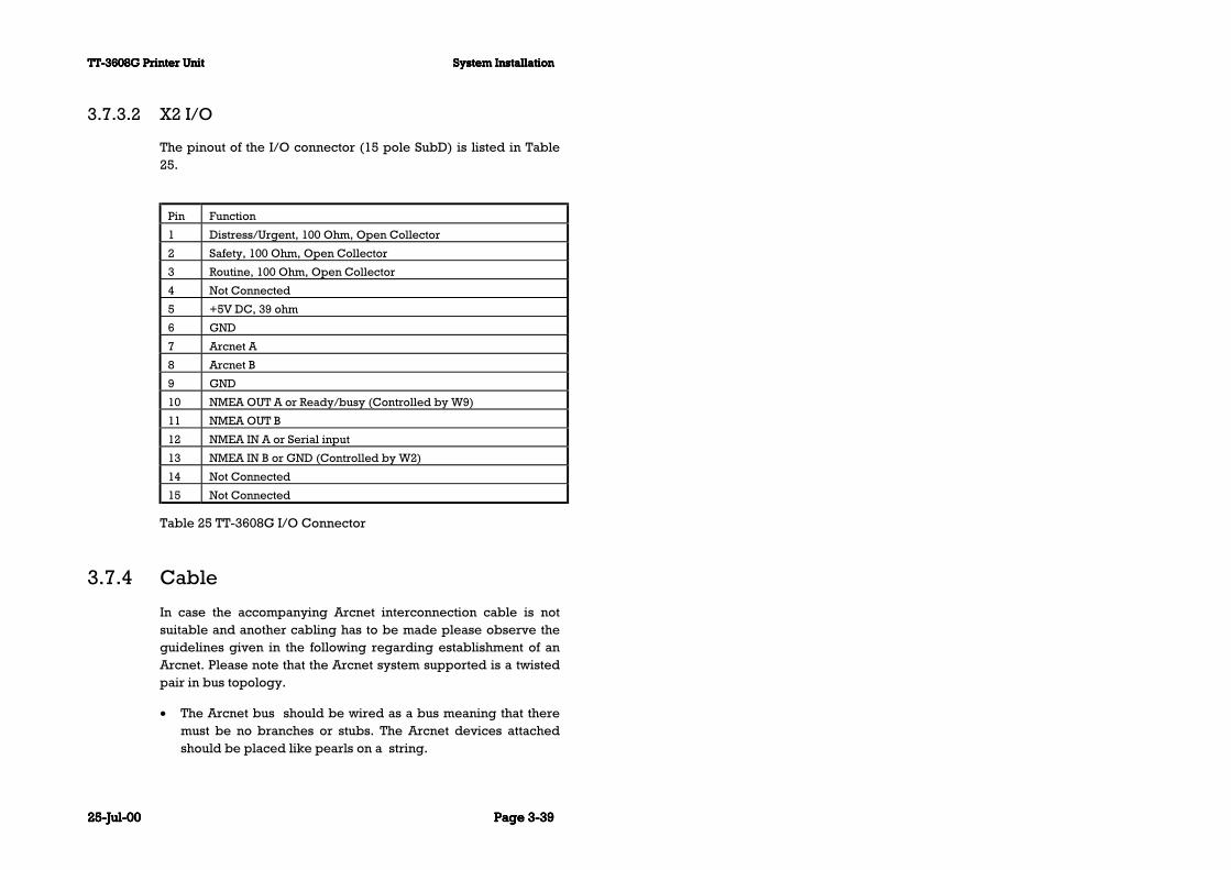
TT-3608G Printer UnitTT-3608G Printer UnitTT-3608G Printer UnitTT-3608G Printer Unit System InstallationSystem InstallationSystem InstallationSystem Installation
25-Jul-0025-Jul-0025-Jul-0025-Jul-00 Page Page Page Page 3-393-393-393-39
3.7.3.2 X2 I/O
The pinout of the I/O connector (15 pole SubD) is listed in Table25.
Pin Function
1 Distress/Urgent, 100 Ohm, Open Collector
2 Safety, 100 Ohm, Open Collector
3 Routine, 100 Ohm, Open Collector
4 Not Connected
5 +5V DC, 39 ohm
6 GND
7 Arcnet A
8 Arcnet B
9 GND
10 NMEA OUT A or Ready/busy (Controlled by W9)
11 NMEA OUT B
12 NMEA IN A or Serial input
13 NMEA IN B or GND (Controlled by W2)
14 Not Connected
15 Not Connected
Table 25 TT-3608G I/O Connector
3.7.4 Cable
In case the accompanying Arcnet interconnection cable is notsuitable and another cabling has to be made please observe theguidelines given in the following regarding establishment of anArcnet. Please note that the Arcnet system supported is a twistedpair in bus topology.
• The Arcnet bus should be wired as a bus meaning that theremust be no branches or stubs. The Arcnet devices attachedshould be placed like pearls on a string.

System InstallationSystem InstallationSystem InstallationSystem Installation TT-3608G Printer UnitTT-3608G Printer UnitTT-3608G Printer UnitTT-3608G Printer Unit
Page Page Page Page 3-403-403-403-40 25-Jul-0025-Jul-0025-Jul-0025-Jul-00
• The Arcnet bus will have two ends and both of these should beterminated with a 100 Ohm resistor (± 1%). The TT-3608Gdoes NOT contain any termination-resistor. If needed the ter-mination resistor could be placed in the 15 pole SubD con-nector connected to the twisted pair cable. This is the case forthe accompanying cable.
• Always use shielded twisted pair cables and shielded con-nectors (otherwise the EMC specifications are not guarantiedto be fulfilled).
• The length of the cable making up the Arcnet bus should beno longer than 100 meters.
• Minimum spacing between devices connected to the Arcnetbus is 2 meter of cable.
• No more than 8 Arcnet devices (including transceiver) mustbe connected to the Arcnet bus.

TT-3608G Printer UnitTT-3608G Printer UnitTT-3608G Printer UnitTT-3608G Printer Unit System InstallationSystem InstallationSystem InstallationSystem Installation
25-Jul-0025-Jul-0025-Jul-0025-Jul-00 Page Page Page Page 3-413-413-413-41
3.7.5 Specifications
Indication Visual: LED indicators with dim function.
Text back-light with dim function.
Call reset OK button
Arcnet/serial
port
DB 15M
conn:
Arcnet: Twisted pair/bus topology,
max 100 meter cable.
Serial port: NMEA 0183 receiver
input optically isolated, NMEA
0183 generator output or Serial
print input with Ready/Busy control
Printer Type: 112 mm thermal printer with two
motors.
Width: 40 char/line normal.
80 char/line compressed.
Speed: 1 l/sec (normal).
Character
size:
9 dot high x 7 dot wide.
direction:
Normal/Reverse, logic seek, word
wrap.
Paper roll: Width 112 mm, diam. 48 mm,
length 25 m.
Supply Voltage: 10.5-32 V floating DC.
Power: 2.5W standby, 7W printing.
Temperature Operating: -10 to +50 Deg.C
Storage: -20 to +70 Deg.C
Relative humidity 95% non-condensing.
Vibration 2-15.8 Hz: 1.0 mm peak.
15.8-100 Hz: 1.0 g peak.
Dimensions HxWxD: 117.5 mm x 213.9 mm x 57.5 mm.
Weight: 1.3 kg.
Table 26 TT-3608G Technical Specifications

System InstallationSystem InstallationSystem InstallationSystem Installation TT-3042C Remote Alarm/Distress Box (optional)TT-3042C Remote Alarm/Distress Box (optional)TT-3042C Remote Alarm/Distress Box (optional)TT-3042C Remote Alarm/Distress Box (optional)
Page Page Page Page 3-423-423-423-42 25-Jul-0025-Jul-0025-Jul-0025-Jul-00
3.8 TT-3042C Remote Alarm/DistressBox (optional)The TT-3042C Remote Alarm/Distress Box is connected to the TT-3020C by means of the Transceivers X4 I/O connector, throughwhich it is also powered.
Figure 23 TT-3042C Remote Alarm/Distress Box
From the Remote Alarm/Distress Box TT-3042C Distress Alertscan be initiated. The TT-3042C also has an indicator for receptionof EGC messages with distress/urgent priority. A Distress Alertcan be initiated by pressing the Distress button for five seconds.
Included in the box is a Distress Relay, which makes it possible tocontrol an external alarm panel. The function of the relay can beselected by setting two internal jumpers according to the specifi-cations in Table 28 TT-3042C Technical Specifications. In casejumper W1 is set to enable the Distress Relay, it will be activatedby an initiation of a distress alert and upon a reception of a mes-sage with distress priority.

TT-3042C Remote Alarm/Distress Box (optional)TT-3042C Remote Alarm/Distress Box (optional)TT-3042C Remote Alarm/Distress Box (optional)TT-3042C Remote Alarm/Distress Box (optional) System InstallationSystem InstallationSystem InstallationSystem Installation
25-Jul-0025-Jul-0025-Jul-0025-Jul-00 Page Page Page Page 3-433-433-433-43
The light intensity of the Power indicator can be adjusted by aknob below it.
J1 PINJ1 PINJ1 PINJ1 PIN TTTTTTTT-3042C Description-3042C Description-3042C Description-3042C Description X4 PINX4 PINX4 PINX4 PIN Satellite Communica-tion Unit
1 + 7.5 - 12 Volt 5 +9Volt for ext. devices2 GND + Safety GND † 6 GND3 Distress button-lamp 1 In/Out 04 Buzzer/Buzzer knob 2 In/Out 15 To Distress Relay 3 In/Out 26 To Fault Relay 4 In/Out 37 Distress button 14 In 48 GND 15 In 59 Distress Relay contact pole 1
10 Distress Relay contact pole 211 Fault Relay contact pole 112 Fault Relay contact pole 2
Table 27 TT-3042C and Satellite Communication Unit inter-connection
Note †: Cable screen included
The cable used for the connection between the TT-3042C RemoteAlarm/Distress Box and the TT-3020C Transceiver, has to be cho-sen in accordance with the specifications in Table 28 TT-3042CTechnical Specifications.
The Remote Alarm/Distress Box is in full compliance with the In-marsat CN114, IEC 945 and Wheel Mark specifications.
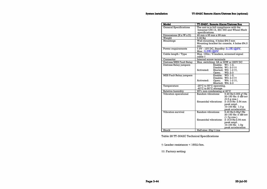
System InstallationSystem InstallationSystem InstallationSystem Installation TT-3042C Remote Alarm/Distress Box (optional)TT-3042C Remote Alarm/Distress Box (optional)TT-3042C Remote Alarm/Distress Box (optional)TT-3042C Remote Alarm/Distress Box (optional)
Page Page Page Page 3-443-443-443-44 25-Jul-0025-Jul-0025-Jul-0025-Jul-00
ModelModelModelModel TTTTTTTT-3042C, Remote Alarm/Distress Box-3042C, Remote Alarm/Distress Box-3042C, Remote Alarm/Distress Box-3042C, Remote Alarm/Distress BoxGeneral Specifications The unit is in full compliance with the
Inmarsat CN114, IEC 945 and Wheel Markspecifications.
Dimensions (H x W x D) 49 mm x 95 mm x 99 mmWeight 0.32 KgMountings Wall mounting, 4 holes Ø4.0 mm
Mounting bracket for console, 4 holes Ø4.0mm
Power requirements 7.5V - 12V DC, Standby: 0.1W/@9V,Max.: 0.5W/@9V
Cable length / Type Max. 100m / 8 leaders, screened signalcable †
Connector Internal screw terminalsDistress/MES Fault Relay Max. switching: 2A or 60W or 220V DCDistress Relay jumpers Enable; W1: 1-2,
Disable; W1: 2-3 ††Activated: Shorted; W2: 1-2 ††,
Open; W2: 2-3MES Fault Relay jumpers Enable; W3: 1-2,
Disable; W3: 2-3 ††Activated: Open; W4: 1-2 ††,
Shorted; W4: 2-3Temperature -25°C to 55°C operating,
-40°C to 80°C storageRelative humidity 95% non-condensing at 40°CVibration operational Random vibrations: 5-20 Hz:0.005 g²/Hz
20-150 Hz:-3 dB/oct(0.5 g rms.)
Sinusoidal vibrations: 2-15.8 Hz: 2.54 mm peak ampl.10-100 Hz: 1.0 g peak acceleration
Vibration survival Random vibrations: 5-20 Hz:0.05g²/Hz20-150 Hz:-3 dB/oct(1.7g rms.)
Sinusoidal vibrations: 2-15.8 Hz:2.54 mm peak ampl.10-100 Hz: 1.0g peak acceleration
Shock Half sine: 20g/11ms
Table 28 TT-3042C Technical Specifications
†: Leader resistance < 160Ω/km.
††: Factory setting

TT-3042C Remote Alarm/Distress Box (optional)TT-3042C Remote Alarm/Distress Box (optional)TT-3042C Remote Alarm/Distress Box (optional)TT-3042C Remote Alarm/Distress Box (optional) System InstallationSystem InstallationSystem InstallationSystem Installation
25-Jul-0025-Jul-0025-Jul-0025-Jul-00 Page Page Page Page 3-453-453-453-45
3.8.1 Mounting
Figure 24 TT-3042C Outline drawing

System InstallationSystem InstallationSystem InstallationSystem Installation TT-3042C Remote Alarm/Distress Box (optional)TT-3042C Remote Alarm/Distress Box (optional)TT-3042C Remote Alarm/Distress Box (optional)TT-3042C Remote Alarm/Distress Box (optional)
Page Page Page Page 3-463-463-463-46 25-Jul-0025-Jul-0025-Jul-0025-Jul-00
Figure 25 TT-3042C Outline drawing with console bracket

TT-3042C Remote Alarm/Distress Box (optional)TT-3042C Remote Alarm/Distress Box (optional)TT-3042C Remote Alarm/Distress Box (optional)TT-3042C Remote Alarm/Distress Box (optional) System InstallationSystem InstallationSystem InstallationSystem Installation
25-Jul-0025-Jul-0025-Jul-0025-Jul-00 Page Page Page Page 3-473-473-473-47
Figure 26 TT-3042C Mounting stencil.
Fasten the TT-3042C Remote Alarm/Distress Box from the insideor by using the mounting bracket, which makes console mountingpossible.
If required, the cable relief are easily moved from the end of theTT-3042C to the bottom feed hole for hidden cable installation.
It is possible to connect 2 TT-3042C’s in parallel to the TT-3020CCapsat Transceiver, from which they are supplied with power andcontrol signals in one cable. The used cable has to be in compli-ance with the specifications in Table 28 TT-3042C TechnicalSpecifications.

System InstallationSystem InstallationSystem InstallationSystem Installation TT-3042D Remote Alarm / Printer UnitTT-3042D Remote Alarm / Printer UnitTT-3042D Remote Alarm / Printer UnitTT-3042D Remote Alarm / Printer Unit
Page Page Page Page 3-483-483-483-48 25-Jul-0025-Jul-0025-Jul-0025-Jul-00
3.9 TT-3042D Remote Alarm / PrinterUnitThe TT-3042D Remote Alarm Distress Box with additional printerunit is an optional unit unless it is used as main printer in aGMDSS system.
Please be advised that a dedicated Reference Manual for the TT-3042D Remote Alarm is available
Figure 27 TT-3042D Remote Alarm Distress Box / Local Printer
The TT-3042D Remote Alarm fulfil all GMDSS requirements forremote indication and printout of EGC SafetyNet messages, ini-tiation of distress transmissions, and general system status dis-play.
The TT-3042D Remote Alarm can be configured as Local Printer ina GMDSS system and will then fulfil all GMDSS requirements forLocal Printers or it can be configured as Remote Alarm with addi-tional printer and will then fulfil all GMDSS requirements for Re-mote Alarms.
TT-3042D Remote Alarm / Printer UnitTT-3042D Remote Alarm / Printer UnitTT-3042D Remote Alarm / Printer UnitTT-3042D Remote Alarm / Printer Unit System InstallationSystem InstallationSystem InstallationSystem Installation
25-Jul-0025-Jul-0025-Jul-0025-Jul-00 Page Page Page Page 3-493-493-493-49
The TT-3042D additional printer unit is printing on 112 mm (4.4")width thermal paper rolls. The printer can be configured for 40 or80 chars/line and automatic word wrapping is performed on longlines. A built-in paper detector indicates when paper is low. Theprinter is temperature compensated to give equal printing qualityover a wide temperature range.
The TT-3042D displays receive mail indication and login status.
Up to six Remote Alarm units and one Local Printer unit all withdifferent Arcnet address setting can be placed on various loca-tions onboard ship, all connected to one TT-3020C Capsat trans-ceiver with Arcnet.
The TT-3042D is equipped with remote turn-on for power savingconfigurations. Remote turn-on is enabled by jumper setting.
3.9.1 Configuration.
Before installation of the TT-3042D, configuration of Arcnet ad-dress should take place.
It is important to observe that all devices connected to the sametransceiver must have different address settings. If this is ignored,the Arcnet will not operate properly. Please notice that if a “net-work problem” info box is displayed on the message terminal theArcnet is not configured properly.
The Printer Unit Arcnet address is configured by setting an 8 po-sition DIP switch located under the paper inlet. To set operatingparameters remove paper and turn off power. In Table 29 thepossible DIP switch settings are listed.
It is through the address setting that the TT-3042D is configuredas either Remote Alarm or Local Printer. If the address is config-ured to 8 (1,1,1) the TT-3042D is configured as Local Printer. Allother addresses are used for Remote Alarm configuration. If theTT-3042D is configured as Local Printer and the Transceiver has a

System InstallationSystem InstallationSystem InstallationSystem Installation TT-3042D Remote Alarm / Printer UnitTT-3042D Remote Alarm / Printer UnitTT-3042D Remote Alarm / Printer UnitTT-3042D Remote Alarm / Printer Unit
Page Page Page Page 3-503-503-503-50 25-Jul-0025-Jul-0025-Jul-0025-Jul-00
printer connected locally on it’s printer port the transceiverprinter is considered as the only Local Printer and the TT-3042Dwill be treated as Remote Alarm with additional printer unit.
Note: Operating parameters are only read at power-up or softre-set so changes in operating parameters will not change operationuntil a power-cycling or softreset is performed.
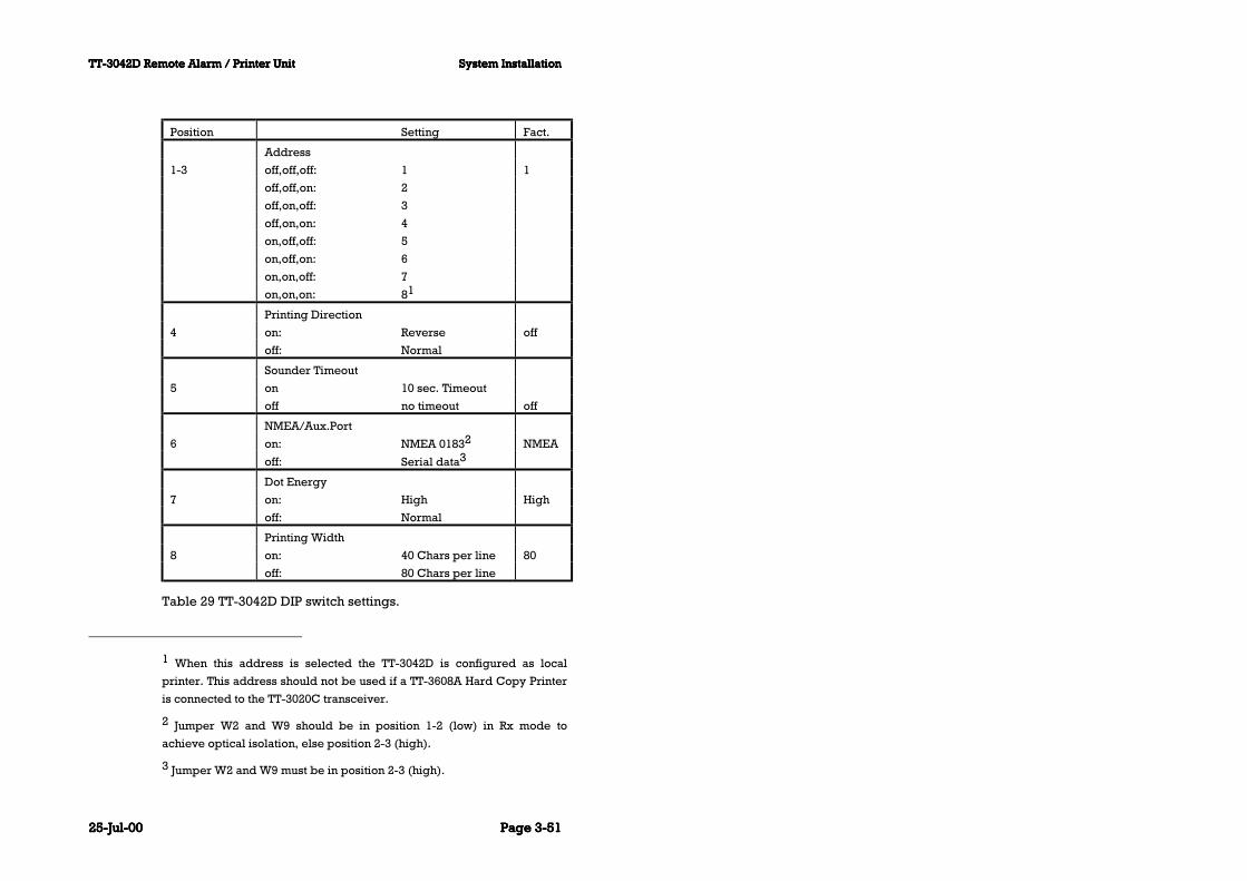
TT-3042D Remote Alarm / Printer UnitTT-3042D Remote Alarm / Printer UnitTT-3042D Remote Alarm / Printer UnitTT-3042D Remote Alarm / Printer Unit System InstallationSystem InstallationSystem InstallationSystem Installation
25-Jul-0025-Jul-0025-Jul-0025-Jul-00 Page Page Page Page 3-513-513-513-51
Position Setting Fact.
Address
1-3 off,off,off: 1 1
off,off,on: 2
off,on,off: 3
off,on,on: 4
on,off,off: 5
on,off,on: 6
on,on,off: 7
on,on,on: 81
Printing Direction
4 on: Reverse off
off: Normal
Sounder Timeout
5 on 10 sec. Timeout
off no timeout off
NMEA/Aux.Port
6 on: NMEA 01832 NMEA
off: Serial data3
Dot Energy
7 on: High High
off: Normal
Printing Width
8 on: 40 Chars per line 80
off: 80 Chars per line
Table 29 TT-3042D DIP switch settings.
1 When this address is selected the TT-3042D is configured as local
printer. This address should not be used if a TT-3608A Hard Copy Printer
is connected to the TT-3020C transceiver.
2 Jumper W2 and W9 should be in position 1-2 (low) in Rx mode to
achieve optical isolation, else position 2-3 (high).
3 Jumper W2 and W9 must be in position 2-3 (high).

System InstallationSystem InstallationSystem InstallationSystem Installation TT-3042D Remote Alarm / Printer UnitTT-3042D Remote Alarm / Printer UnitTT-3042D Remote Alarm / Printer UnitTT-3042D Remote Alarm / Printer Unit
Page Page Page Page 3-523-523-523-52 25-Jul-0025-Jul-0025-Jul-0025-Jul-00
3.9.2 Installation
To following brief outline may be used to get the TT-3042D upand running as a printer together with a Thrane & Thrane trans-ceiver which supports Arcnet - hardware as well as software wise.
1. Set an unique Arcnet address as described in section 3.9.1.2. Connect the 3042D to the transceiver by means of the accom-
panying interconnection cable (15 pole SubD connectors).3. Connect the 3042D to a DC power source by means of the ac-
companying power cable. For security reasons take care toconnect the ground/chassis wire properly to ground.
When power is applied it should now be possible for the trans-ceiver to print on the TT-3042D when needed or initiated by theuser.
3.9.3 Connectors
The connectors for the TT-3042D are placed on the rear panel ofthe printer unit.
3.9.3.1 X1 Power In
The pinout of the power supply input is as listed in Table 30.
Pin Function
1 Battery Positive
2 Battery Negative
3 Ground
4 Remote turn-on
Table 30 TT-3042D Power Connector

TT-3042D Remote Alarm / Printer UnitTT-3042D Remote Alarm / Printer UnitTT-3042D Remote Alarm / Printer UnitTT-3042D Remote Alarm / Printer Unit System InstallationSystem InstallationSystem InstallationSystem Installation
25-Jul-0025-Jul-0025-Jul-0025-Jul-00 Page Page Page Page 3-533-533-533-53
3.9.3.2 X2 I/O
The pinout of the I/O connector (15 pole SubD) is listed in Table31.
Pin Function
1 Distress/Urgent, 100 Ohm, Open Collector
2 Safety, 100 Ohm, Open Collector
3 Routine, 100 Ohm, Open Collector
4 Not Connected
5 +5V DC, 39 ohm
6 GND
7 Arcnet A
8 Arcnet B
9 GND
10 NMEA OUT A or Ready/busy (Controlled by W9)
11 NMEA OUT B
12 NMEA IN A or Serial input
13 NMEA IN B or GND (Controlled by W2)
14 Not Connected
15 Not Connected
Table 31 TT-3042D I/O Connector
3.9.4 Cable
In case the accompanying Arcnet interconnection cable is notsuitable and another cabling has to be made please observe theguidelines given in the following regarding establishment of anArcnet. Please note that the Arcnet system supported is a twistedpair in bus topology.
• The Arcnet bus should be wired as a bus meaning that theremust be no branches or stubs. The Arcnet devices attachedshould be placed like pearls on a string.

System InstallationSystem InstallationSystem InstallationSystem Installation TT-3042D Remote Alarm / Printer UnitTT-3042D Remote Alarm / Printer UnitTT-3042D Remote Alarm / Printer UnitTT-3042D Remote Alarm / Printer Unit
Page Page Page Page 3-543-543-543-54 25-Jul-0025-Jul-0025-Jul-0025-Jul-00
• The Arcnet bus will have two ends and both of these should beterminated with a 100 Ohm resistor (± 1%). The TT-3042Ddoes NOT contain any termination-resistor. If needed the ter-mination resistor could be placed in the 15 pole SubD con-nector connected to the twisted pair cable. This is the case forthe accompanying cable.
• Always use shielded twisted pair cables and shielded con-nectors (otherwise the EMC specifications are not guarantiedto be fulfilled).
• The length of the cable making up the Arcnet bus should beno longer than 100 meters.
• Minimum spacing between devices connected to the Arcnetbus is 2 meter of cable.
• No more than 8 Arcnet devices (including transceiver) mustbe connected to the Arcnet bus.

TT-3042D Remote Alarm / Printer UnitTT-3042D Remote Alarm / Printer UnitTT-3042D Remote Alarm / Printer UnitTT-3042D Remote Alarm / Printer Unit System InstallationSystem InstallationSystem InstallationSystem Installation
25-Jul-0025-Jul-0025-Jul-0025-Jul-00 Page Page Page Page 3-553-553-553-55
3.9.5 Specifications
Indication Visual: LED indicators with dim function.
Text back-light with dim function.
Call reset OK button
Arcnet/serial
port
DB 15M
conn:
Arcnet: Twisted pair/bus topology,
max 100 meter cable.
Serial port: NMEA 0183 receiver
input optically isolated, NMEA
0183 generator output or Serial
print input with Ready/Busy control
Printer Type: 112 mm thermal printer with two
motors.
Width: 40 char/line normal.
80 char/line compressed.
Speed: 1 l/sec (normal).
Character
size:
9 dot high x 7 dot wide.
direction:
Normal/Reverse, logic seek, word
wrap.
Paper roll: Width 112 mm, diam. 48 mm,
length 25 m.
Supply Voltage: 10.5-32 V floating DC.
Power: 2.5W standby, 7W printing.
Temperature Operating: -25 to +55 Deg.C
Storage: -30 to +70 Deg.C
Relative humidity 95% non-condensing.
Vibration 2-15.8 Hz: 1.0 mm peak.
15.8-100 Hz: 1.0 g peak.
Dimensions HxWxD: 117.5 mm x 213.9 mm x 57.5 mm.
Weight: 1.3 kg.
Table 32 TT-3042D Technical Specifications

System InstallationSystem InstallationSystem InstallationSystem Installation Distress Button TestDistress Button TestDistress Button TestDistress Button Test
Page Page Page Page 3-563-563-563-56 25-Jul-0025-Jul-0025-Jul-0025-Jul-00
3.10 Distress Button TestWhen the TT-3000C Maritime system is fully installed, it is rec-ommended to do a distress button test.
The Distress Test Mode facility in the TT-3606E Message terminal(Alt, O, E) allows test of the Distress Buttons, Distress LED's andwiring. When Distress Test Mode option is selected the DistressTest Mode message is displayed:
Test Mode Yes No Distress buttons are under test. Cancel the test mode if a real distress alert needs to be sent. Cancel?
Please notice that the message displayed by the Message Termi-nal asks the operator if distress test mode should be cancelled.Do not answer yes to this question unless you are absolutely surethat you have completed distress testing.
In Distress Test Mode the Distress Buttons can be activated andtested without issuing Distress Alerts. Distress Test Mode is can-celled by pressing the Esc key. After Distress Test Mode is termi-nated activating the Distress Buttons will again result in a DistressAlert being send.
3.10.1 TT-3020C Transceiver
Test of the Distress facility on the Transceiver:
Please note that the transceiver has to be in Distress Test ModePlease note that the transceiver has to be in Distress Test ModePlease note that the transceiver has to be in Distress Test ModePlease note that the transceiver has to be in Distress Test Modebefore this test is performed. Otherwise a real Distress Alert isbefore this test is performed. Otherwise a real Distress Alert isbefore this test is performed. Otherwise a real Distress Alert isbefore this test is performed. Otherwise a real Distress Alert istransmitted.transmitted.transmitted.transmitted.

Distress Button TestDistress Button TestDistress Button TestDistress Button Test System InstallationSystem InstallationSystem InstallationSystem Installation
25-Jul-0025-Jul-0025-Jul-0025-Jul-00 Page Page Page Page 3-573-573-573-57
Pressing the Distress button will make the Distress LED flash andwill activate an intermediate acoustic signal. If the Distress buttonis held for at least 5 seconds the acoustic signal will stop and theDistress LED will light constantly to indicate that a Distress Alert issend. Please see Figure 1.
3.10.2 TT-3042C Remote Alarm/Distress Box
When Distress Test mode is initiated the Remote Alarm Box startsa test sequence. In this sequence the Distress Msg LED, thebuzzer and the MES Fault LED are activated one at a time until theuser presses the buzzer reset button. After that only the buzzer isactivated until the Distress Test mode is stopped.
Test of the Distress Button on the Remote Alarm Box:
Please note that the transceiver has to be in Distress Test ModePlease note that the transceiver has to be in Distress Test ModePlease note that the transceiver has to be in Distress Test ModePlease note that the transceiver has to be in Distress Test Modebefore this test is performed. Otherwise a real Distress Alert isbefore this test is performed. Otherwise a real Distress Alert isbefore this test is performed. Otherwise a real Distress Alert isbefore this test is performed. Otherwise a real Distress Alert istransmitted.transmitted.transmitted.transmitted.
Pressing the Distress button will make the Distress LED flash andwill activate an intermediate acoustic signal. If the Distress buttonis held for at least 5 seconds the acoustic signal will stop and theDistress LED will light constantly to indicate that a Distress Alert issend. Observe that the transceiver reacts by flashing the AlarmLED when the Distress Button has been activated. Figure 23.
3.10.3 TT-3042D Remote Alarm Distress Box
When Distress Test mode is initiated the TT-3042D Remote AlarmBox starts a test sequence. In this sequence first the Dis-tress/Urgent LED is activated for a few seconds and then all theSafety, Routine and Mail LED’s are activated for a few seconds.This sequence continues until Distress Test mode is stopped.While in Distress Test mode the buzzer will generate an interme-diate acoustic signal.

System InstallationSystem InstallationSystem InstallationSystem Installation General interconnect informationGeneral interconnect informationGeneral interconnect informationGeneral interconnect information
Page Page Page Page 3-583-583-583-58 25-Jul-0025-Jul-0025-Jul-0025-Jul-00
Test of the Distress Button on the Remote Alarm Box:
Please note that the transceiver has to be in Distress Test ModePlease note that the transceiver has to be in Distress Test ModePlease note that the transceiver has to be in Distress Test ModePlease note that the transceiver has to be in Distress Test Modebefore this test is performed. Otherwise a real Distress Alert isbefore this test is performed. Otherwise a real Distress Alert isbefore this test is performed. Otherwise a real Distress Alert isbefore this test is performed. Otherwise a real Distress Alert istransmitted.transmitted.transmitted.transmitted.
Pressing the Distress button will make the Distress LED flash andwill activate an intermediate acoustic signal. If the Distress buttonis held for at least 5 seconds the acoustic signal will stop and theDistress LED will light constantly to indicate that a Distress Alert issend. Observe that the transceiver reacts by flashing the AlarmLED when the Distress Button has been activated. Please seeFigure 27.
3.11 General interconnect informationIn Figure 28 is an example of the TT-3000C Maritime Capsat Sys-tem for GMDSS use.
An Integrated Capsat System is delivered with all necessary in-terconnecting cables, except the cable between the TT-3020CTransceiver and the TT-3042C Remote Alarm/Distress Box.

General interconnect informationGeneral interconnect informationGeneral interconnect informationGeneral interconnect information System InstallationSystem InstallationSystem InstallationSystem Installation
25-Jul-0025-Jul-0025-Jul-0025-Jul-00 Page Page Page Page 3-593-593-593-59
x2
x4TT-3020C
Solas GMDSSTranseiver
x5
x3 x1
TT-3042CRemote Alarm Box
TT-3680BPower Supply
AC/DC225W
TT-3606EMessage Terminal
TT-3601EKeyboard
TT-3608AOKI Printer
with DC option
220V/110VAC
24V DC
NMEA in/out
ArcNet
Alarm I/O
EIA-232
Centronics
I/O
ArcNet
DC
DC
DC
DCTT-3608GPrinter Unit
Floating DC
NMEA
Capsat
TT-3005MAntenna Unit
Figure 28 Interconnection diagram
The TT-3608A printer can be substituted with the compactprinter/alarm panel TT-3042D (please see section 3.9) if specialrequirement exist for a compact solution.
For applications where cables will be handmade by the dealer orthe customer it is important to note that the cable screen shouldbe soldered to the connector frame to prevent static electricshocks. A complete set of connectors are delivered together withan Integrated Capsat System.

System InstallationSystem InstallationSystem InstallationSystem Installation General interconnect informationGeneral interconnect informationGeneral interconnect informationGeneral interconnect information
Page Page Page Page 3-603-603-603-60 25-Jul-0025-Jul-0025-Jul-0025-Jul-00
This page is intentionally left blank

Terminal ModeTerminal ModeTerminal ModeTerminal Mode System GenerationSystem GenerationSystem GenerationSystem Generation
25-Jul-0025-Jul-0025-Jul-0025-Jul-00 Page Page Page Page 4-14-14-14-1
4 System Generation
4.1 Terminal ModeThe TT-3020C Capsat Transceiver parameters may be accom-plished by means of:
TT-3606E Message Terminal.
Computerised equipment.
Handheld terminals, etc.
Please follow the below listed guide lines to set up the connectedequipment in a direct terminal emulating manner.
In terminal emulation mode a ':' prompt appears.
The commands are executed by pressing the <CR> key.
4.1.1 TT-3606E Message Terminal
Enter the terminal emulation mode by selecting:
OPTIONS - CONFIGURATION - TERMINAL
4.1.2 Computerised equipment/handheldterminals
Your computer/terminal should display the ASCII characters asthey appear being send from the TT-3020C Capsat Transceiver.
No alphabet or protocol conversion should take place.

System GenerationSystem GenerationSystem GenerationSystem Generation Initialise System ParametersInitialise System ParametersInitialise System ParametersInitialise System Parameters
Page Page Page Page 4-24-24-24-2 25-Jul-0025-Jul-0025-Jul-0025-Jul-00
4.2 Initialise System ParametersThe System Parameters are initialised using the 'set -b' command.
After issuing this command a menu appears with a number of ini-tialisation options.
:set - b<CR>
Init system parameters menu 0 Quit 1 All 2 Basic system parameters 3 EGC Network ID's 4 Data Network ID's 5 LES Network Table 6 Link Test ResultsEnter number >
4.2.1 Entering your mobile number
The Mobile Number in the Transceiver is entered using the 'set -u'command.:set -u ?<CR>Mobile Number : 492380049Enter new number >
An Inmarsat-C mobile number is always in the range:
400000000 to 499999999
If you type a number outside this range the Transceiver will ig-nore it.
You should not attempt to use your equipment before, you havereceived a mobile number, because the Mobile Number means

Initialise System ParametersInitialise System ParametersInitialise System ParametersInitialise System Parameters System GenerationSystem GenerationSystem GenerationSystem Generation
25-Jul-0025-Jul-0025-Jul-0025-Jul-00 Page Page Page Page 4-34-34-34-3
that you have been registered in the database for the Inmarsat-CNetwork.
The Transceiver only uses the mobile number when sendingMessage Position Reports (see the Message Handling SoftwareOperators Guide), to indicate which Transceiver originated theposition message.
4.2.2 Altering baudrate and protocol settings
The baudrate and protocol settings can be changed by the com-mand :
: se -c
Console-status : 4800,N,8,1
Software handshake : no
:
: se -c ?
Enter parameters as baudrate,parity,databits,
stopbits > 4800,N,8,1
Software handshake Y/N > n
Factory settings is obtained by pressing the Stop button at power-on.
Please notice that changing the baudrate or other protocol set-tings in terminal mode only changes the transceiver configura-tion. It is therefore necessary also to change the Message Termi-nal serial port settings to the identical configuration otherwise thesystem will not function properly.
On the Message Terminal this is done in the “Application - Sys-tem — Option — Serial Ports” menu.
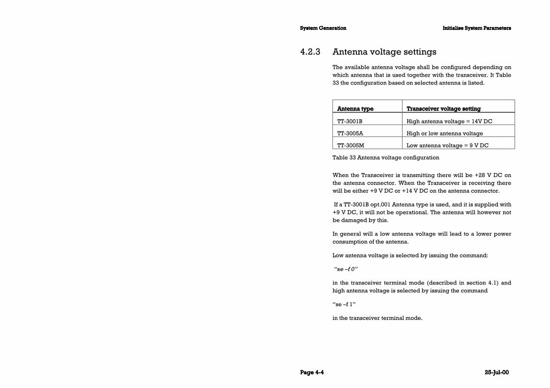
System GenerationSystem GenerationSystem GenerationSystem Generation Initialise System ParametersInitialise System ParametersInitialise System ParametersInitialise System Parameters
Page Page Page Page 4-44-44-44-4 25-Jul-0025-Jul-0025-Jul-0025-Jul-00
4.2.3 Antenna voltage settings
The available antenna voltage shall be configured depending onwhich antenna that is used together with the transceiver. It Table33 the configuration based on selected antenna is listed.
Antenna typeAntenna typeAntenna typeAntenna type Transceiver voltage settingTransceiver voltage settingTransceiver voltage settingTransceiver voltage setting
TT-3001B High antenna voltage = 14V DC
TT-3005A High or low antenna voltage
TT-3005M Low antenna voltage = 9 V DC
Table 33 Antenna voltage configuration
When the Transceiver is transmitting there will be +28 V DC onthe antenna connector. When the Transceiver is receiving therewill be either +9 V DC or +14 V DC on the antenna connector.
If a TT-3001B opt.001 Antenna type is used, and it is supplied with+9 V DC, it will not be operational. The antenna will however notbe damaged by this.
In general will a low antenna voltage will lead to a lower powerconsumption of the antenna.
Low antenna voltage is selected by issuing the command:
“se —f 0”
in the transceiver terminal mode (described in section 4.1) andhigh antenna voltage is selected by issuing the command
“se —f 1”
in the transceiver terminal mode.

Initialise System ParametersInitialise System ParametersInitialise System ParametersInitialise System Parameters System GenerationSystem GenerationSystem GenerationSystem Generation
25-Jul-0025-Jul-0025-Jul-0025-Jul-00 Page Page Page Page 4-54-54-54-5
If the TT-3005M antenna is used and the antenna voltage is set tohigh run the transceiver will probably set-up a warning box stat-ing that the antenna is not connected.

System GenerationSystem GenerationSystem GenerationSystem Generation Initialise System ParametersInitialise System ParametersInitialise System ParametersInitialise System Parameters
Page Page Page Page 4-64-64-64-6 25-Jul-0025-Jul-0025-Jul-0025-Jul-00
This page is intentionally left blank

IntroductionIntroductionIntroductionIntroduction CommissioningCommissioningCommissioningCommissioning
25-Jul-0025-Jul-0025-Jul-0025-Jul-00 Page Page Page Page 5-15-15-15-1
5 Commissioning
5.1 IntroductionBefore attempting to use the equipment, the commissioning pa-pers should be send to the relevant authority.
It is recommended that a Link Test (or Performance VerificationTest in Inmarsat terminology) is run before using the equipment.
The Link Test automatically verifies that the TT-3020C CapsatTransceiver is capable of both receiving and transmitting infor-mation according to Inmarsat-C specifications. No other tests arerequired.
The Inmarsat Mobile Number is needed to run the Link Test.
When a new unit is being installed, it is the responsibility of theservice technician to verify that the unit is functioning properly,and that the unit is commissioned and logged into the Inmarsat-CSystem, at the end of installation.
You should only attempt to start one Link Test yourself as youhave only three commissioning attempts, and these will be usedup if you are not cautious.
5.2 The first LoginYour first Login attempt will be recognised by the Network Co-ordinating Station (NCS) and served normally, (downloading aLand Earth Station (LES) network table into the Transceiver) andinform the Network Database that the new unit is present andbeing commissioned.

CommissioningCommissioningCommissioningCommissioning Link TestLink TestLink TestLink Test
Page Page Page Page 5-25-25-25-2 25-Jul-0025-Jul-0025-Jul-0025-Jul-00
The TT-3020C Capsat Transceiver is now logged in and ready towork.
5.3 Link TestThe Link Test consist of three parts:
Message Reception Test
Message Transmission Test and
Distress Test.
The TT-3020C will automatically perform a distress test withoutany user intervention.
In the end of the test the Transceiver will receive the link test re-sults.
5.4 Details of a Link TestYou should try to start one link test yourself to verify the unit
After a while you will see a message on your screen and on yourprinter saying:
---- Link Test started
and when the MAIL indicator on the TT-3020C front panel startsflashing, the receive test has commenced.
A test message is then received from the LES by the Transceiver.
After the MAIL indicator has turned OFF, the transmission test be-gins.

Details of a Link TestDetails of a Link TestDetails of a Link TestDetails of a Link Test CommissioningCommissioningCommissioningCommissioning
25-Jul-0025-Jul-0025-Jul-0025-Jul-00 Page Page Page Page 5-35-35-35-3
The SEND indicator starts flashing and after a while it will lightcontinuously (the data is being transmitted) and then starts flash-ing again.
The SEND indicator will turn OFF when the protocol has finished.
The Transceiver now automatically sends a Distress Alert test.
The printer will give an acknowledgement when the Alert hasbeen sent.
The Transceiver now will wait for the test results to arrive fromthe LES, and acknowledge the reception of these by a shorttransmission (burst).
When receiving the results the screen will display:---- Link Test finished
and the results will be printed out.
The results of the test can also be viewed with:---- OPTION - LINK TEST

CommissioningCommissioningCommissioningCommissioning Details of a Link TestDetails of a Link TestDetails of a Link TestDetails of a Link Test
Page Page Page Page 5-45-45-45-4 25-Jul-0025-Jul-0025-Jul-0025-Jul-00
This page is intentionally left blank

IndexIndexIndexIndex
25-Jul-0025-Jul-0025-Jul-0025-Jul-00 Page Page Page Page 6-16-16-16-1
6 Index
A
Antenna not connected................................................................................ 4-5Distress button ............................................................................................ 2-6Antenna cable .....................................................................................3-8, 3-13Antenna safe distance........................................................................3-18, 3-21ArcNet .................................................................................................2-2, 2-11
B
Baudrate................................................................................................2-9, 4-3
C
Cable loss .................................................................................. 3-8, 3-13, 3-17Compass safe Distance..........................................................................2-3, 3-3
D
Distress alert ............................................................................................. 3-42Distress button .......................................................................................... 3-42Distress button test .................................................................................... 3-56Distress indicator ........................................................................................ 2-6DTE connector............................................................................................. 2-9DTR and CTS signals.................................................................................. 2-11
F
Flow control .............................................................................................. 2-11Fuse.......................................................................................................2-4, 3-2
G
Galvanic isolation........................................................................................ 2-9GMDSS ....................................................................................... 3-6, 3-11, 3-15GPS ........................................................................................................... 2-17
I
I/O connector ............................................................................................ 2-11

IndexIndexIndexIndex
Page Page Page Page 6-26-26-26-2 25-Jul-0025-Jul-0025-Jul-0025-Jul-00
L
LES...............................................................................................................2-6Link test ................................................................................................5-1, 5-2Login indicator.............................................................................................2-6
M
Mail indicator...............................................................................................2-6Mobile number .....................................................................................4-2, 5-1
N
NCS..............................................................................................................5-1NMEA 0183 communication .......................................................................2-11
O
On/off features.............................................................................................2-4Operating temperature....................................................................... 2-2, 3-26
P
Power connector ..........................................................................................2-7Power indicator............................................................................................2-5Printer port ................................................................................................2-15
R
Radar or navigator cables .......................................................... 3-8, 3-13, 3-17Remote Alarm/Distress Box........................................................................3-42Remote power control...........................................................................2-5, 2-8RF grounding .............................................................................................2-17RS-423 ports ...............................................................................................3-24
S
SafetyNet EGC messages...........................................................................3-42Send indicator..............................................................................................2-6Serial communication cable length ............................................................2-11Serial port communication ...........................................................................2-9Shipping carton............................................................................................1-2Stop button...................................................................................................2-5Storage temperature ....................................................................................1-2

IndexIndexIndexIndex
25-Jul-0025-Jul-0025-Jul-0025-Jul-00 Page Page Page Page 6-36-36-36-3
T
Technical specifications, TT-3020C .....................................................2-1, 3-26