car parking system design in vhdl
TRANSCRIPT
CAR PARKING SYSTEM DESIGN IN VHDL
This Thesis submitted in partial fulfillment of the requirements for the Award of
Degree of Bachelor of Science in Electrical and Electronic Engineering
Submitted by
Iffat Jahan
ID: 153-33-2848
Pankoz Chandra Das
ID: 153-33-3034
Supervised by
Dr. Md. Rezwanul Ahsan
Assistant Professor
Department of Electrical & Electronic Engineering
Faculty of Engineering
Department of Electrical and Electronic Engineering
Faculty of Engineering
DAFFODIL INTERNATIONAL UNIVERSITY
January 2019
© Daffodil International University ii
CERTIFICATION
This is to certify that this project entitled “CAR PARKING SYSTEM DESIGN IN
VHDL” is done by the following students under my direct supervision. This project
work has been carried out by them in the laboratories of the Department of Electrical
and Electronic Engineering under the Faculty of Engineering, Daffodil International
University in partial fulfillment of the requirements for the degree of Bachelor of
Science in Electrical and Electronic Engineering. The presentation of the work was
held on ……….. 2019.
Signature of the candidates
_____________________
Iffat Jahan
ID: 153-33-2848
________________________
Pankoz Chandra Das
ID: 153-33-3034
Signature of the supervisor
Dr. Md. Rezwanul Ahsan
Assistant Professor, Dept. of EEE
© Daffodil International University iii
Daffodil International University

© Daffodil International University iv
Dedicated to
Our Parents
© Daffodil International University v
CONTENTS
CONTENTS iv -vi
LIST OF FIGURE vii-viii
LIST OF TABLE ix
LIST OF ABBREVIATIONS x
ACKNOWLEDGEMENT xi
ABSTRACT xii
CHAPTER 1 INTRODUCTION 1-4
1.1 Introduction 1
1.2 Issues of Old System of Vehicles Parking 2
1.2.1 Traffic Jam 2
1.2.2 Security Issue 2
1.2.3 Wasting Time 3
1.2.4 Economic Loss 3
1.3 Advantage of Auto Car Parking System 3
1.3.1 Reduce Traffic Jam 3
1.3.2 Save Time 3
1.3.3 Reduce Attendance 3
1.4 Objective of Project 3
1.5 Background of the Project 4
CHAPTER 2 LITERATURE REVIEW 6-12
2.1 Overview 6
2.2 History of Car Parking System 6
2.3 Manual Car Parking System 6
2.4 Automatic Car Parking System 6
2.4.1 Fully Automated Car Parking System 6
2.4.2 Semi-Automated Car Parking System 7
2.5 Development of auto Car Parking System 7
© Daffodil International University vi
2.6 Car Parking System in Bangladesh 7
2.7 Applicability of This Project 8
2.8 Comparison Between the Existing System and
Proposed System
9
2.9 State Machine 10
2.10 Explanation about Software 10
2.10.1 Quartus II Software 10
2.10.2 Benefit of Using VHDL 12
CHAPTER 3 METHODOLOGY 13-32
3.1 Introduction 13
3.2 Direction of Car Parking System 14
3.3 Developing Diagram and Interface Signal of Car
Parking System
15
3.4 State Diagram of Car Parking System 16
3.5 Working Procedure of Proto Type 17
3.5.1 The Display 17
3.5.2 The Gate 18
3.5.3 The Central Command 19
3.5.4 The exit 20
3.6 Implementation in VHDL 20
3.7 Compile Program in Quartus II Software 20
3.7.1 Getting Started with Altera Quartus II 20
3.7.2 Create a New Project 21
3.7.3 Choosing a Device 21
3.7.4 Creating a New File 22
3.7.5 Created a Test Bench 24
3.8 Analyzing Synthesis Results With the Net List Viewers 25
3.8.1 The RTL Viewer 25
3.8.2 State Machine Viewer 26
3.8.3 The Technology Map Viewer 26
3.8.4 The Pin Planner 27
3.9 Hardware Components 28
© Daffodil International University vii
3.9.1 Altera FPGA Board 28
3.9.2 Sensor 29
3.9.3 LED Display 29
3.9.4 Relay 30
3.9.5 H-Bridge 31
3.9.6 Power Supply 31
3.10 Summary 32
CHAPTER 4 RESULTS AND DISCUSSION 33-36
4.1 Introduction 33
4.2 Results for Automated Car Parking System 33
4.3 Discussion 36
CHAPTER 5 CONCLUSION 37-38
5.1 Conclusion 37
5.2 Future Ideas 37
5.2.1 Smart Acknowledgement of Vehicles 37
5.2.2 Updating Users About Accessible Slots and Record
Balance
38
5.3 Commercialization Potential 38
REFERENCES 39
APPENDIX A 40
APPENDIX B 44
© Daffodil International University viii
LIST OF FIGURES
Fig 1.1 Existing Car Parking System 1
Fig 1.2 Proposed Car Parking System 2
Fig 2.1 Fully Automated Car Parking System 7
Fig 2.2 Quartus II Design Flow 11
Fig 3.1 Flow Chart of Car Parking System Design 13
Fig 3.2 Automatic Car Parking System 14
Fig 3.3 Interface Diagram 16
Fig 3.4 Finite State Machine 17
Fig 3.5 Flow Chart for the Display 18
Fig 3.6 Flow Chart for the Gate 19
Fig 3.7 Flow Chart for the Central Command 19
Fig 3.8 Opening Quartus II Software 20
Fig 3.9 Creating New Project Wizard 21
Fig 3.10 Selecting a Device 22
Fig 3.11 Creating a New File 23
Fig 3.12 VHDL Code Compilation 23
Fig 3.13 Compilation Report 24
Fig 3.14 Generating a Test Bench 24
Fig 3.15 Compilation Report on Test Bench 25
Fig 3.16 RTL Viewer 25
Fig 3.17 State Machine Viewer 26
Fig 3.18 Technology Map Viewer 27
Fig 3.19 Pin Planner 27
Fig 3.20 Altera FPGA Board 29
Fig 3.21 Different Type of Light Sensor 29
Fig 3.22 LED 30
Fig 3.23 A Typical 7- Segment LED Display 30
Fig 3.24 Relay 31
Fig 3.25 H-Bridge 31
Fig 3.26 Power Supply 32
Fig 4.1 Diagram Showing Simulation Result of Car Parking System 33
© Daffodil International University ix
Fig 4.2 Diagram Showing Simulation Result of Car Parking System 34
Fig 4.3 Wave form of front_sensor = [email protected] 34
Fig 4.4 Wave form of GREEN_LED= [email protected] 35
Fig 4.5 Wave form of RED_LED= [email protected] 35
Fig 4.6 Wave form of RED_LED=1 and back_sensor [email protected] 36
© Daffodil International University x
LIST OF TABLES
Table 3.1 List of inputs and outputs terminals of the state machine 15
© Daffodil International University xi
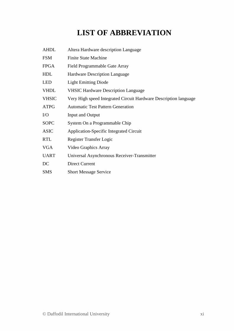
LIST OF ABBREVIATION
AHDL Altera Hardware description Language
FSM Finite State Machine
FPGA Field Programmable Gate Array
HDL Hardware Description Language
LED Light Emitting Diode
VHDL VHSIC Hardware Description Language
VHSIC Very High speed Integrated Circuit Hardware Description language
ATPG Automatic Test Pattern Generation
I/O Input and Output
SOPC System On a Programmable Chip
ASIC Application-Specific Integrated Circuit
RTL Register Transfer Logic
VGA Video Graphics Array
UART Universal Asynchronous Receiver-Transmitter
DC Direct Current
SMS Short Message Service
© Daffodil International University xii
ACKNOWLEDGEMENT
It is a great pleasure for authors to express their unfettered gratification, sincere
appreciation and profound respect to our respective supervisor Dr. Md. Rezwanul
Ahsan, Assistant Professor, Department of Electrical & Electronic Engineering,
Daffodil International University, for his constructive suggestion, scholastic guidance,
constant inspiration, valuable advices and kind co-operation for the successful
completion of work on “Car Parking System Design in VHDL”. This could not be
possible without his help.
Space does not allow us to mention each person by name, but we are deeply grateful
to everyone associated with this thesis. We also wish to complement all our respective
concern teachers & staffs of our department of their direct and indirect assistance at
different times.
© Daffodil International University xiii
ABSTRACT
Presently multi day's vehicle parking is a basic issue and step by step its necessity is
expanding. In Bangladesh we are as yet utilizing the manual vehicle parking
framework and that is the reason we are confronting issues like wastage of time and
fuel discovering free space around the parking ground when we have to park our
vehicle which requires a decent measure of lighting. Another issue is clutter that
occurs while parking on the grounds that there is no specific framework anybody can
park anyplace that at some point makes harm the vehicles while moving out or in the
parking area. Security is likewise an issue there.
To tackle these issues we are exhibiting new vehicle parking system. The system fills
in as pursues: where the quantity of accessible stopping spaces will be shown in the
LED display. While stopping out the driver should give the code to the administrator
at the leave gate.
The work presented in this paper gives more insight and deeper understanding of
constituting modules of parking system. This paper investigates the optimized parking
system through FPGA employing "logic forgathers" including multiple registers as
their logic block. And we show that this algorithm is superior to an existing packing
algorithm.
© Daffodil International University 1
CHAPTER 1
INTRODUCTION
1.1 Introduction
Transportation has continually been a crucial aspect of human civilization but in the
dynamic evolution of present time, the amount of vehicles are increasing in a rapid
manner that produces traffic dirtiness and crowding unreliable parking problems. We
live in a country that is developing radically. For this reason, presently we are facing a
great deal of very much reached streets, business place and developing amount of
vehicles.
When people want to park these vehicles they use the manual technique they park
their cars any place they want. They park their cars beside road which creates a huge
traffic jam. Sometimes absence of enough space cars can get scratched by knocking
with one another. This prompts contentions battles among people which some of the
time make immense car influx. Because of parking in the congested road our valuable
time is hampered. It harms student, employee and crisis patients all things considered.
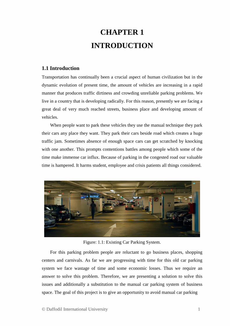
Figure: 1.1: Existing Car Parking System.
For this parking problem people are reluctant to go business places, shopping
centers and carnivals. As far we are progressing with time for this old car parking
system we face wastage of time and some economic losses. Thus we require an
answer to solve this problem. Therefore, we are presenting a solution to solve this
issues and additionally a substitution to the manual car parking system of business
space. The goal of this project is to give an opportunity to avoid manual car parking
© Daffodil International University 2
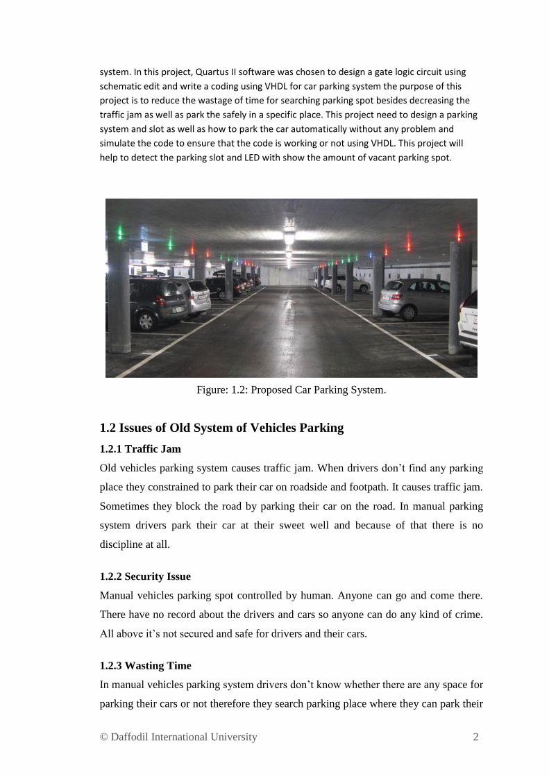
system. In this project, Quartus II software was chosen to design a gate logic circuit using
schematic edit and write a coding using VHDL for car parking system the purpose of this
project is to reduce the wastage of time for searching parking spot besides decreasing the
traffic jam as well as park the safely in a specific place. This project need to design a parking
system and slot as well as how to park the car automatically without any problem and
simulate the code to ensure that the code is working or not using VHDL. This project will
help to detect the parking slot and LED with show the amount of vacant parking spot.
Figure: 1.2: Proposed Car Parking System.
1.2 Issues of Old System of Vehicles Parking
1.2.1 Traffic Jam
Old vehicles parking system causes traffic jam. When drivers don‟t find any parking
place they constrained to park their car on roadside and footpath. It causes traffic jam.
Sometimes they block the road by parking their car on the road. In manual parking
system drivers park their car at their sweet well and because of that there is no
discipline at all.
1.2.2 Security Issue
Manual vehicles parking spot controlled by human. Anyone can go and come there.
There have no record about the drivers and cars so anyone can do any kind of crime.
All above it‟s not secured and safe for drivers and their cars.
1.2.3 Wasting Time
In manual vehicles parking system drivers don‟t know whether there are any space for
parking their cars or not therefore they search parking place where they can park their
© Daffodil International University 3
cars. Sometimes at a time more than one or two drivers try to park their cars at same
place and when they create jam sometimes they quarrel with each other to park their
cars. It wastes their time and sometimes hampers their cars as well.
1.2.4 Economic Loss
In manual car parking system there is a risk to collision with cars and it is hampering
the car which may need to repair. So they have to pay for that.
1.3 Advantage of Auto Car Parking System
Population is growing in our country and so is the growing traffic management in our
country. Mechanized vehicle leaving frameworks in such countries for at times have
furnished alleviation since they accompanied various points of interest
The advantages of automated car parking systems are:
1.3.1: Reduce Traffic Jam
In auto car parking system drivers park their cars in a parking spot so there is no
chance to park their car on the roadside or footpath. Which reduce traffic jam.
1.3.2: Save Time
When there is less traffic jam then it will save the valuable time of travelers. They can
park their car without wasting their time.
1.3.3: Reduce Attendance
People can park their car by themselves. They do not need any attendance to show
them where to park their car. The LED display will show the number of empty
parking slot.
1.4 Objective of Project
The main objectives for the project is to create program of intelligent car parking
system in real life. This project also ensure a safe and secured parking system to
assign the right way and minimizes the waste of time for trying to find out free
parking space.
The objectives are below:
© Daffodil International University 4
To implement the FSM of an intelligent car parking system on software
based.
To introduce automatic car parking system in our country and get benefits
from it.
To ensure safety and security while park the car.
Park car without guided by park attendance.
Park car without wastage of time.
1.5 Background of the Project
Day by day our country has been advanced drastically, now we are in this state that
we have a lot of well-constructed roads, commercial building and increasing number
of automobiles. With the increasing amount of roads and highways transportation has
become the backbone of our day to day life. Transportation has also become the
strength of our economy for its wide usage in trade and business. Hence, it has been a
matter of thought to park these transportations and vehicles in safe places. We still use
the very old fashioned manual procedure of parking when it comes parking these
vehicles. These are maintained in unplanned manner, without any discipline. Due to
this system people can park their cars anywhere they want to, which creates a mess as
people don‟t follow the discipline most of the time. While parking in and recovering
car due mismanagement cars can get dent by bumping with each other as there is lack
of sufficient space. This leads to arguments, fights among people which sometimes
create traffic jam. This is also an economical lose as we need to repair our damaged
car. Due to this disorder in parking our valuable time gets wasted. It harms the
students, office going staffs and emergency patients to an excessive scope. It also
causes economical loss to commercial places like shopping malls, amusement parks
as people are more likely not to visit these places due to this parking hazard.
Automated car parking systems will provide several benefits. It will save time and
fuel cost. In manual parking system it is too hard to find out the vacant space for
parking, it is very much time consuming. Sometimes it causes late in meeting or other
important works. It will save fuel as in this system an automatic car parking the
vehicle into the required slot. This will reduce the fuel cost of probing for parking
space. Here we do not need to lighting all over the parking space all the time. It will
only have the lights on when it moves and where is the path and it is very much
electricity saving also. It provides security from theft of vehicle and it can earn
© Daffodil International University 5
revenue. It can introduce us to advanced digitalized systems which show us the
Engineering excellence in our country.
© Daffodil International University 6
CHAPTER 2
LITERATURE REVIEW
2.1 Overview
Car parking system in Bangladesh has become one of the biggest problem in city life.
Number of vehicles are increasing so that the manual car parking system is not
enough. It is difficult to find out a parking place in main cities to park vehicles. There
are several alternatives have been established to reduce this problem. But these are not
enough to park a car safe and secure. Therefore more efficient methods need to be
researched and developed for solving the problem. Here will discuss about the manual
car parking system, automatic car parking system and the proposed car parking
system.
2.2 History of Car Parking System
Since, the eve of car invention cars were needed to be parked in a place. In the early
20th
century car parking systems were developed. Over the years technology have
developed and diversified.
2.3 Manual Car Parking System
In manual car parking system drivers search a place for parking their cars. When they
find out parking place first they ensure that whether the place is empty or not. If there
are available parking slots then they have to collect a pass by paying required parking
amount. After fulfill the requirement they can park their cars.
2.4 Automatic Car Parking System
Automatic car parking system was first introduced in Europe. Early in the 19th
century
and in the North America in the 1920.
There are two kinds of automatic car parking systems are:
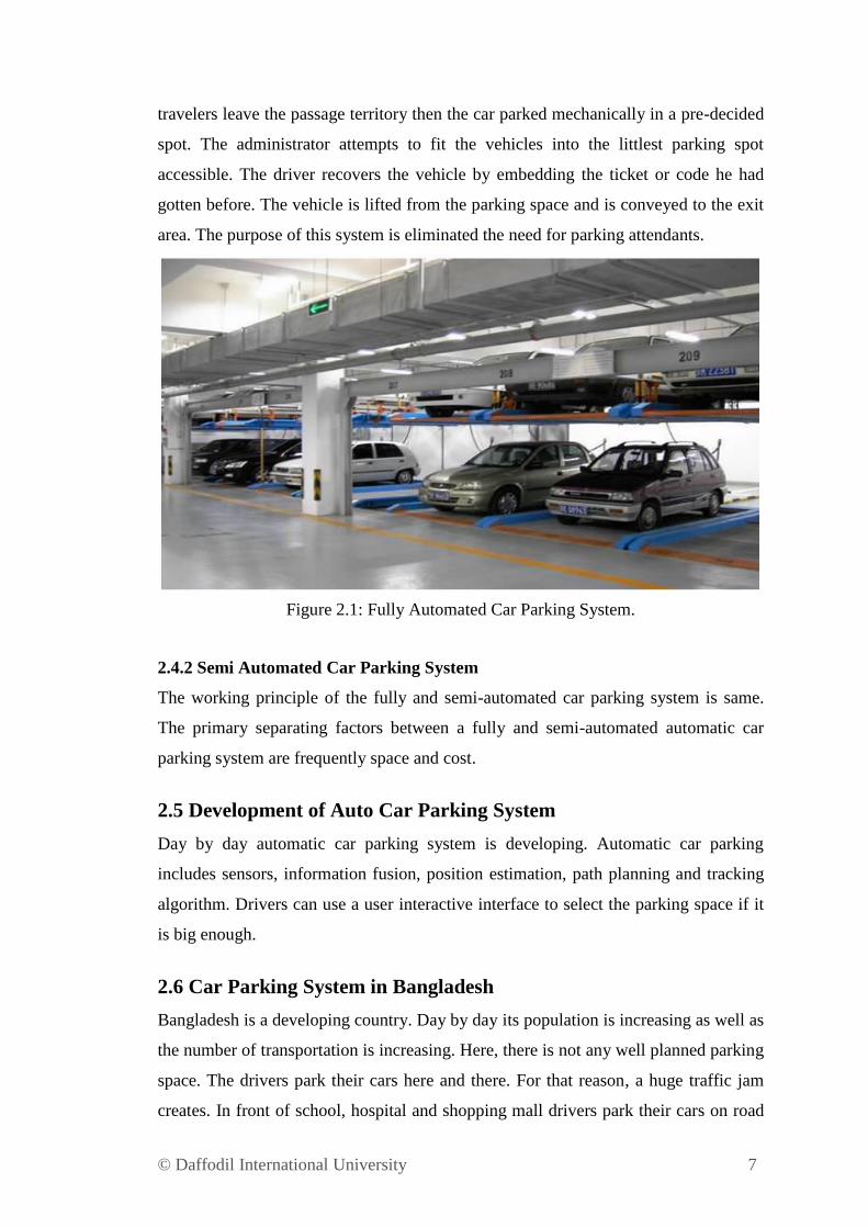
2.4.1 Fully Automated Car Parking System
This parking system is completely robotized. The drivers need to take the cars until
the passage zone. The car must be cleared. The driver does installment in a
computerized terminal adjacent and he gets the ticket. When everyone of the car‟s
© Daffodil International University 7
travelers leave the passage territory then the car parked mechanically in a pre-decided
spot. The administrator attempts to fit the vehicles into the littlest parking spot
accessible. The driver recovers the vehicle by embedding the ticket or code he had
gotten before. The vehicle is lifted from the parking space and is conveyed to the exit
area. The purpose of this system is eliminated the need for parking attendants.
Figure 2.1: Fully Automated Car Parking System.
2.4.2 Semi Automated Car Parking System
The working principle of the fully and semi-automated car parking system is same.
The primary separating factors between a fully and semi-automated automatic car
parking system are frequently space and cost.
2.5 Development of Auto Car Parking System
Day by day automatic car parking system is developing. Automatic car parking
includes sensors, information fusion, position estimation, path planning and tracking
algorithm. Drivers can use a user interactive interface to select the parking space if it
is big enough.
2.6 Car Parking System in Bangladesh
Bangladesh is a developing country. Day by day its population is increasing as well as
the number of transportation is increasing. Here, there is not any well planned parking
space. The drivers park their cars here and there. For that reason, a huge traffic jam
creates. In front of school, hospital and shopping mall drivers park their cars on road
© Daffodil International University 8
side or footpath. For this kind of car parking system passers-by cannot walk properly
also occurred traffic jam. Without some well established companies, hospitals and
shopping mall there is no car parking place. So their clients park their cars on the
roadside and create a disturbance in the area.
Some companies have come forward to change the manual car parking system. Some
automated car parking system is under process as like “PI Lab Company” advertise
and encourage to use automatic car parking system.
2.7 Applicability of this Project
Over the vacant with the advancement of our country is such that the old manual
system of car parking in business spaces should be supplanted. The old manual
system of a car park is creating obstacle as well as tumult in parking spot, accordingly
bringing about wastage of time and some financial misfortunes also. Along these lines
presenting Automated Car Parking Systems in business areas can be substitution to
the manual car parking systems. We can introduce this system in the spots like:
Office Buildings
In this system office workers can easily park their cars without any obstacle and
losing their time. It will likewise alleviate their psyche from the pointless parking
obstacle. Likewise, in the event that somebody is as of now late he would not be late
anymore by searching for the parking spot and park his vehicle. It will likewise give
security to their vehicles from taking away.
Shopping Malls
It will assist the clients with parking their vehicles with no obstacle and it will give
them an opportunity to temples for more items. It will profit both the clients and the
venders as the client will have more opportunity to investigate their alternatives and
the merchants have more item choices to move. It will build the quantity of clients
coming in the shopping centers. It will expand income as the client needs to pay for
the parking spot. It will likewise assist expelling the vehicles which are being parked
throughout the day without shopping purposes as they will be charged for parking
their autos. As there is a perimeter for the parking spot the clients will remember that
and they will expel their vehicles on time. This will assist more clients with coming to
these shopping centers every day. It will be safekeeping to their vehicles from taking.
© Daffodil International University 9
Hospitals
In healing facility when there are a ton of crisis cases there are a ton of a vehicles and
ambulances coming in the parking spot. This makes stick which is the reason of delay
for the patients to get the therapeutic administrations, which frequently can be lethal
to them. In the event that we introduce the robotized system, it will set aside less
opportunity to leave vehicle and the patients to achieve the restorative
administrations. Likewise they can win income for vehicles other than the
ambulances. It will likewise give security to their vehicles from taking.
Carnivals
In the event that we introduce mechanized vehicle parking systems in entertainment
meccas it will draw in more peoples to go to these spots. The more income will be
earned the more the general population will come. In addition these entertainment
meccas calm us from our monotonous and repetitive lives, revives our brain. The
more peoples can appreciate these spots because of the propelled parking office. It
again expands the income as peoples need to pay for parking their vehicles. It will
likewise give assurance to their autos from taking. Alongside these spots we can
utilize this framework in instructive foundations and mosques where vehicle parking
region is accessible. It will assist peoples with parking their vehicle effectively
without making any obstacle. It will likewise give assurance to their autos from
taking.
2.8 Comparison between the Existing System and Proposed System
In present days we are confronting numerous issues with the current vehicle parking
system. As we have to park our vehicle physically and there is no control in this
procedure it makes an enormous obstacle. Peoples can park their vehicles any places
they need to, which makes a wreck as peoples don't pursue a specific sign more often
than not. Because of this a colossal congested driving conditions happens in that put.
While parking in and recovering vehicle due bungle autos can get scratch by knocking
with one another as there is absence of adequate space. This prompts contentions,
battles among peoples which now and then make car influx. This is additionally a
conservative lose as we have to fix our harmed vehicle. This turmoil likewise prompts
vehicles devouring additional fuel.
© Daffodil International University 10
Car influx is a concern because it hampers our valuable time. Because of this
mayhem in parking our significant time gets squandered. For spots like shopping
centers or entertainment meccas it causes practical misfortune, as because of this
bedlam many peoples are reluctant to visit these spots which decline the quantity of
the clients in these spots. Again the clients inspire less time to peruse for choices
through these spots which can again diminishes the chance to moving the items. Once
in a while the clients can't enter in these spots because of this parking disarray. This
vehicle parking risk causes issue for the pupil and the office workers as they can't
achieve their goal on time which once in a while causes enormous misfortune in their
individual vocation. It can make lethal harm the patients as it can make delay for them
achieve the restorative administrations might be only a couple of floor away in the
doctor's facility building. Additionally there is no installment framework for vehicle
leaving in the vast majority of the parking spots in our country. So by presenting the
mechanized car parking systems we can deal with the both of parking spot spare time
and recoup misfortunes caused by the current framework and furthermore win cash by
charging cash for vehicle parking.
2.9 State Machine
For designing a computer program or digital logic the state machine concept can be
used. There are two types of state machine, one is finite and another one is infinite.
Our project will work using the finite state machine concept. State machines are
spoken to utilizing state charts. The yield of a state machine is an element of the
information and the present state. It is easy to design and gives the designer great
flexibility when the designer needs to weak the design either for speed or area
optimization.
2.10 Explanation about Software
A software is used for simulation. In this project, VHDL (VHSIC Hardware
Description Language) is used for writing a code using Quartus11 software. After
writing and simulate the code to see whether the theme is working or not.
2.10.1 Quartus11 Software
The Altera Quartus11 structure software gives an entire, multiplatform plan condition
that effectively adjusts to explicit design needs. It is a thorough situation for system
© Daffodil International University 11
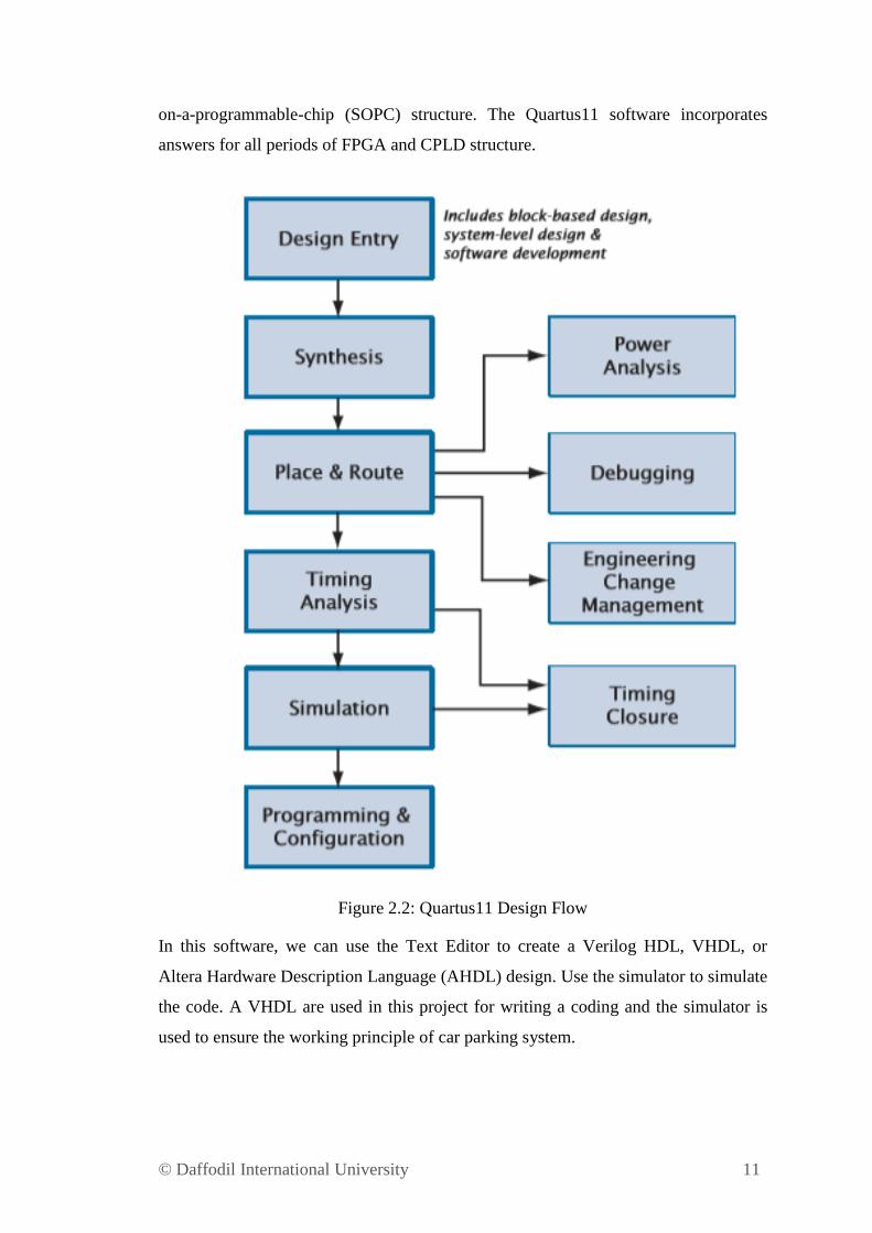
on-a-programmable-chip (SOPC) structure. The Quartus11 software incorporates
answers for all periods of FPGA and CPLD structure.
Figure 2.2: Quartus11 Design Flow
In this software, we can use the Text Editor to create a Verilog HDL, VHDL, or
Altera Hardware Description Language (AHDL) design. Use the simulator to simulate
the code. A VHDL are used in this project for writing a coding and the simulator is
used to ensure the working principle of car parking system.
© Daffodil International University 12
2.10.2 Benefit of Using VHDL
VHDL is generally used to write text models that describe a logic circuit. Such a
model is processed by a synthesis program, only if it is part of the logic design. A
simulation program is used to test the logic design using simulation models to
represent the logic circuits that interface to the design. This collection of simulation
models is commonly called a test bench.
Hardware description language (HDL) is divided by two types, Verilog and
VHDL (VHSIC – Very High Speed Integrated Circuit Hardware Description
Language). Both have its advantages and disadvantages. In this project, VHDL was
chosen because it‟s
Executable specification
Validate spec in system context (Subcontract)
Functionality separated from implementation
Simulate early and fast (Manage complexity)
Explore design alternatives
Get feedback (Produce better designs)
Automatic synthesis and test generation (ATPG for ASICs)
Increase productivity (Shorten time-to-market)
Technology and tool independence (though FPGA features may be
unexploited)
Portable design data (Protect investment)
The advantages using VHDL are shown below
Standard Language
Powerful and versatile description language
Multiple mechanisms to support design hierarchy

© Daffodil International University 13
CHAPTER 3
METHODOLOGY
3.1 Introduction
In this chapter discuss about process and design of a car parking system.
Figure 3.1: Flow Chart of Car Parking System Design
This project consists of two parts, design a program and implement this with software.
Quartus II software was chosen for designing a program of the car parking system. In
this software VHDL text editor is used to design of car parking system. After finish
write a codding, continue with simulate to get wave form in software.
© Daffodil International University 14
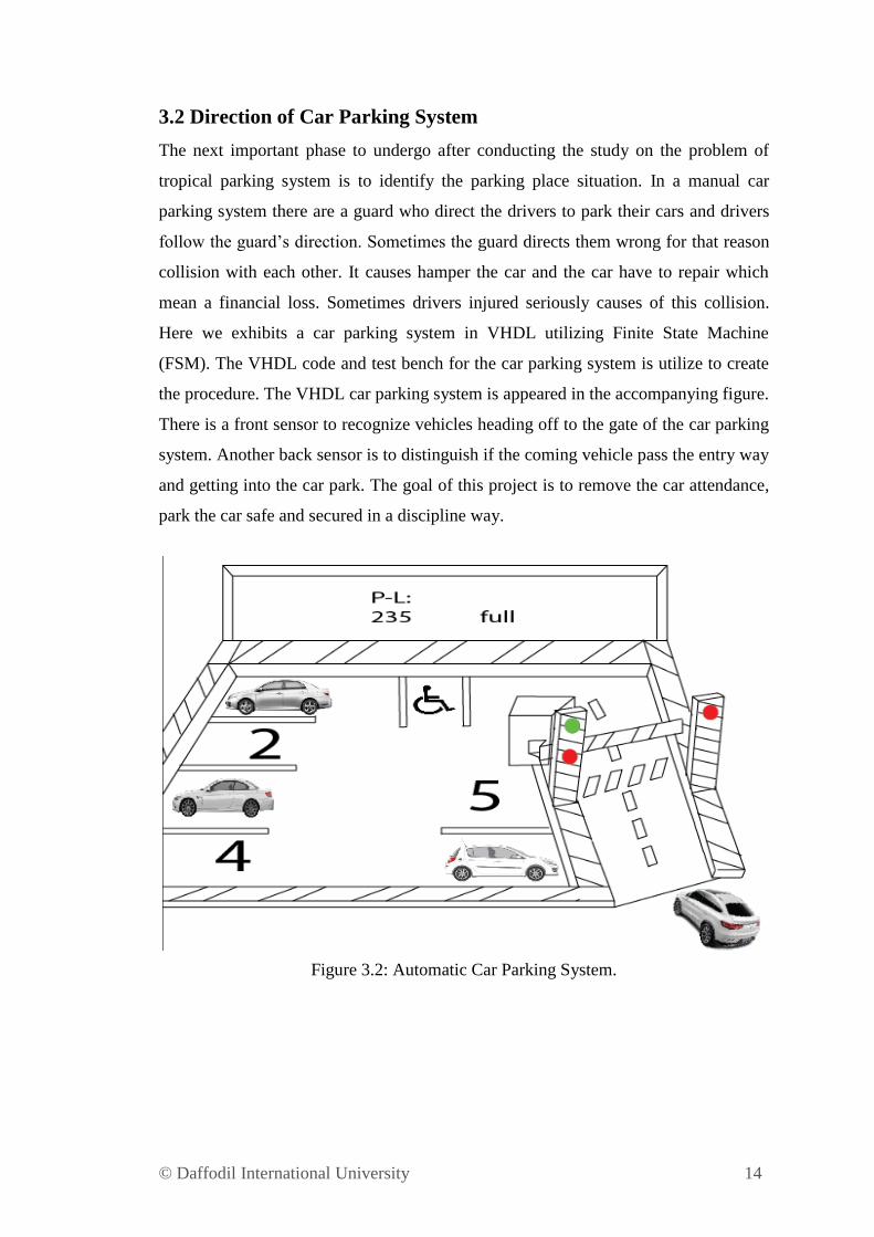
3.2 Direction of Car Parking System
The next important phase to undergo after conducting the study on the problem of
tropical parking system is to identify the parking place situation. In a manual car
parking system there are a guard who direct the drivers to park their cars and drivers
follow the guard‟s direction. Sometimes the guard directs them wrong for that reason
collision with each other. It causes hamper the car and the car have to repair which
mean a financial loss. Sometimes drivers injured seriously causes of this collision.
Here we exhibits a car parking system in VHDL utilizing Finite State Machine
(FSM). The VHDL code and test bench for the car parking system is utilize to create
the procedure. The VHDL car parking system is appeared in the accompanying figure.
There is a front sensor to recognize vehicles heading off to the gate of the car parking
system. Another back sensor is to distinguish if the coming vehicle pass the entry way
and getting into the car park. The goal of this project is to remove the car attendance,
park the car safe and secured in a discipline way.
Figure 3.2: Automatic Car Parking System.
© Daffodil International University 15
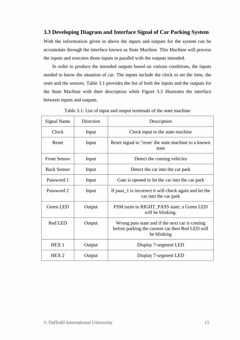
3.3 Developing Diagram and Interface Signal of Car Parking System
With the information given in above the inputs and outputs for the system can be
accumulate through the interface known as State Machine. This Machine will process
the inputs and executes those inputs in parallel with the outputs intended.
In order to produce the intended outputs based on various conditions, the inputs
needed to know the situation of car. The inputs include the clock to set the time, the
reset and the sensors. Table 3.1 provides the list of both the inputs and the outputs for
the State Machine with their description while Figure 3.3 illustrates the interface
between inputs and outputs.
Table 3.1: List of input and output terminals of the state machine
Signal Name Direction Description
Clock Input Clock input to the state machine
Reset Input Reset signal to "reset- the state machine to a known
state
Front Sensor Input Detect the coming vehicles
Back Sensor Input Detect the car into the car park
Password 1 Input Gate is opened to let the car into the car park
Password 2 Input If paas_1 is incorrect it will check again and let the
car into the car park
Green LED Output FSM turns to RIGHT_PASS state; a Green LED
will be blinking.
Red LED Output Wrong pass state and if the next car is coming
before parking the current car then Red LED will
be blinking
HEX 1 Output Display 7-segment LED
HEX 2 Output Display 7-segment LED
© Daffodil International University 16
Figure 3.3: Interface Diagram
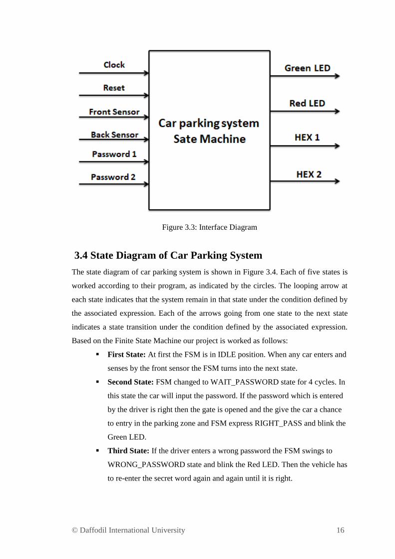
3.4 State Diagram of Car Parking System
The state diagram of car parking system is shown in Figure 3.4. Each of five states is
worked according to their program, as indicated by the circles. The looping arrow at
each state indicates that the system remain in that state under the condition defined by
the associated expression. Each of the arrows going from one state to the next state
indicates a state transition under the condition defined by the associated expression.
Based on the Finite State Machine our project is worked as follows:
First State: At first the FSM is in IDLE position. When any car enters and
senses by the front sensor the FSM turns into the next state.
Second State: FSM changed to WAIT_PASSWORD state for 4 cycles. In
this state the car will input the password. If the password which is entered
by the driver is right then the gate is opened and the give the car a chance
to entry in the parking zone and FSM express RIGHT_PASS and blink the
Green LED.
Third State: If the driver enters a wrong password the FSM swings to
WRONG_PASSWORD state and blink the Red LED. Then the vehicle has
to re-enter the secret word again and again until it is right.
© Daffodil International University 17
Fourth State: When password is right the car gets into the parking zone
and identified by the back sensor. If there is another car coming to park the
FSM turns into STOP state and blink the Red LED. The Red LED is
blinking for the following car to notice to stop and the password. The FSM
comes back to the IDLE state after the car passes the gate and gets into the
car park.
Figure 3.4: Finite State Machine
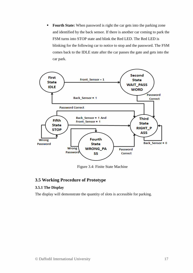
3.5 Working Procedure of Prototype
3.5.1 The Display
The display will demonstrate the quantity of slots is accessible for parking.
© Daffodil International University 18
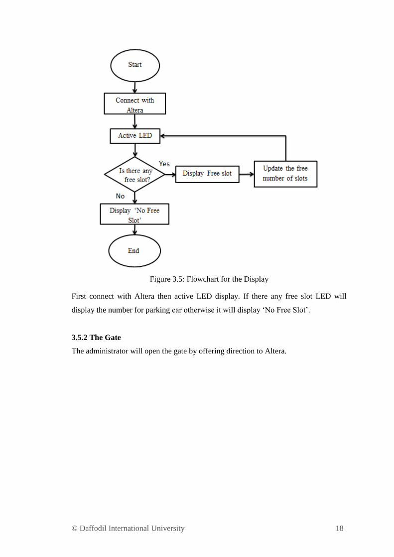
Figure 3.5: Flowchart for the Display
First connect with Altera then active LED display. If there any free slot LED will
display the number for parking car otherwise it will display „No Free Slot‟.
3.5.2 The Gate
The administrator will open the gate by offering direction to Altera.
© Daffodil International University 19
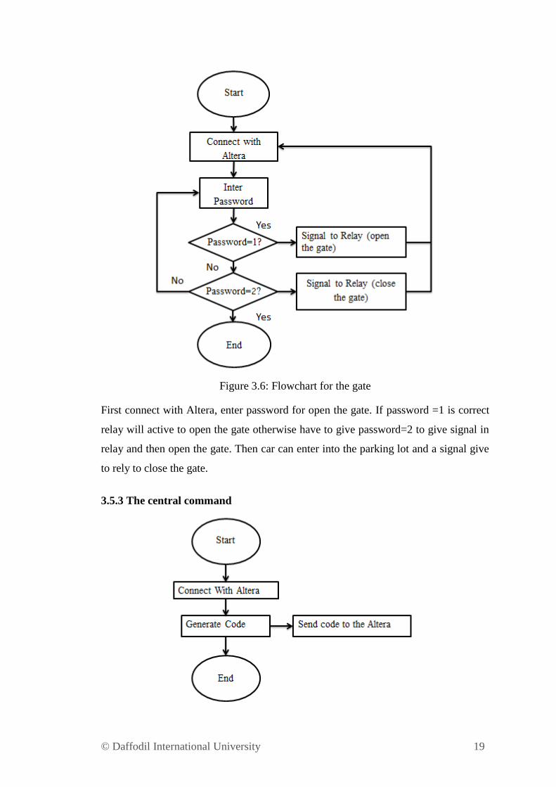
Figure 3.6: Flowchart for the gate
First connect with Altera, enter password for open the gate. If password =1 is correct
relay will active to open the gate otherwise have to give password=2 to give signal in
relay and then open the gate. Then car can enter into the parking lot and a signal give
to rely to close the gate.
3.5.3 The central command
© Daffodil International University 20
Figure 3.7: Flow Chart for the central command
Connect with Altera and generate the code using software. Send code to the Altera.
Now Altera can do the central work for car parking.
3.5.4 The Exit
Wait until the previous car is parked. And continue the process again.
3.6 Implementation in VHDL
The Finite State Machine (FSM) of Intelligent Car Parking System will be used as a
reference in writing the VHDL code. The states shown in the FSM will act as a
reference case in the code to indicate the condition of the sensors. Quartus11 software
is used to writing the code and simulates it. The code will work according to the FSM.
After simulate the code we can identify that our code is working or not according to
our desire.
3.7 Compile Program in Quartus II Software
In Quartus II software we can generate code and compile it. In our project we used
Quartus II 9.1 (64-Bit). First we open the software then create a file and the file name
must similar with the entity name. Open a new file then from there select VHDL file.
Here we write our program and compile it.
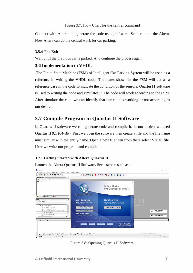
3.7.1 Getting Started with Altera Quartus II
Launch the Altera Quartus II Software. See a screen such as this
Figure 3.8: Opening Quartus II Software.
© Daffodil International University 21
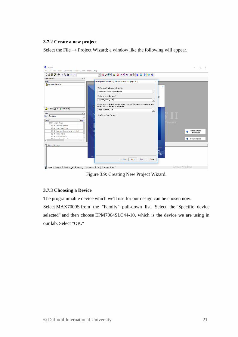
3.7.2 Create a new project
Select the File → Project Wizard; a window like the following will appear.
Figure 3.9: Creating New Project Wizard.
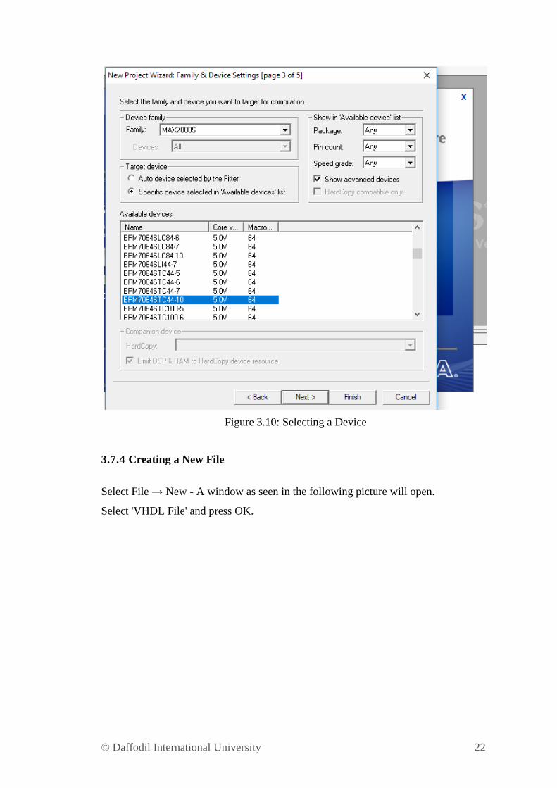
3.7.3 Choosing a Device
The programmable device which we'll use for our design can be chosen now.
Select MAX7000S from the "Family" pull-down list. Select the "Specific device
selected" and then choose EPM7064SLC44-10, which is the device we are using in
our lab. Select "OK."
© Daffodil International University 22
Figure 3.10: Selecting a Device
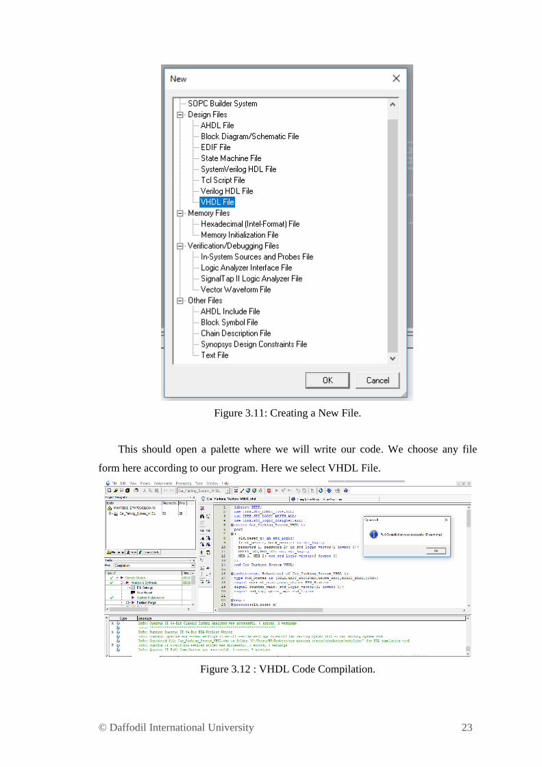
3.7.4 Creating a New File
Select File → New - A window as seen in the following picture will open.
Select 'VHDL File' and press OK.
© Daffodil International University 23
Figure 3.11: Creating a New File.
This should open a palette where we will write our code. We choose any file
form here according to our program. Here we select VHDL File.
Figure 3.12 : VHDL Code Compilation.
© Daffodil International University 24
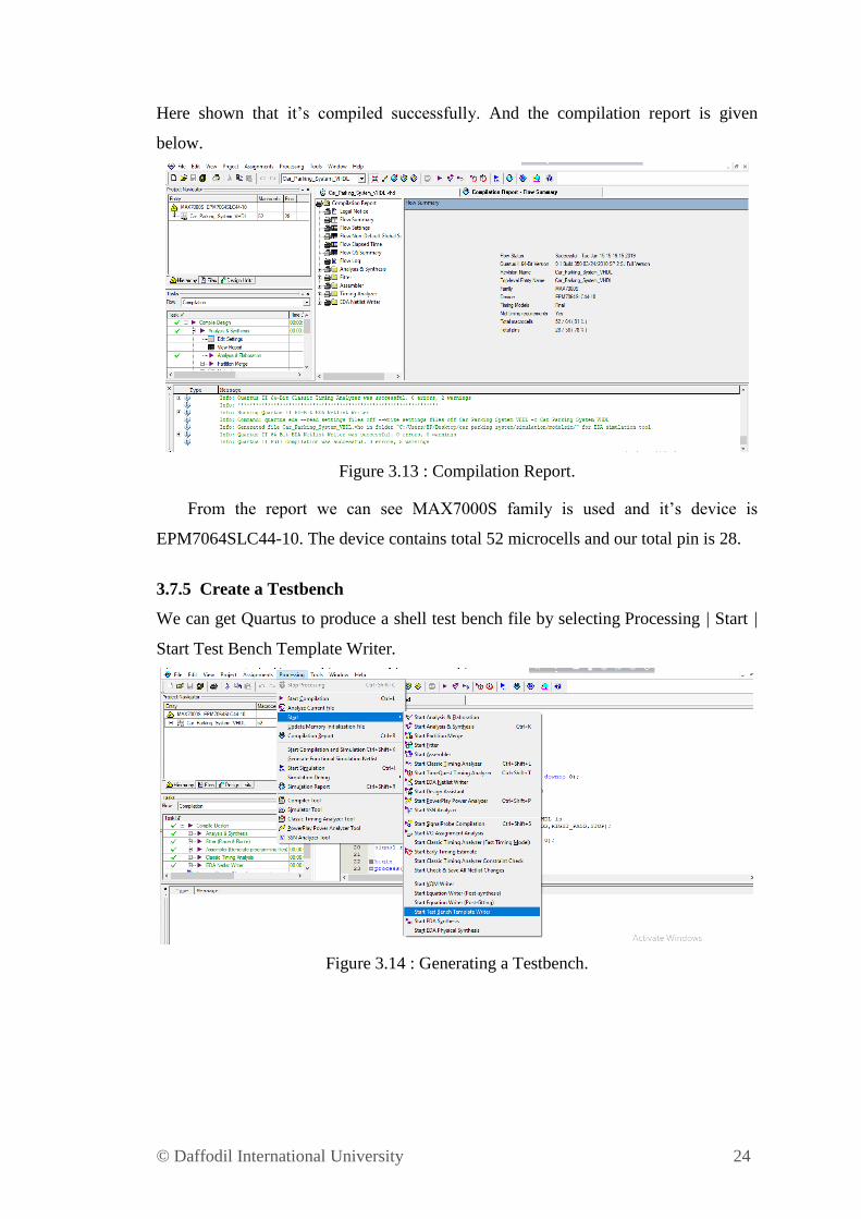
Here shown that it‟s compiled successfully. And the compilation report is given
below.
Figure 3.13 : Compilation Report.
From the report we can see MAX7000S family is used and it‟s device is
EPM7064SLC44-10. The device contains total 52 microcells and our total pin is 28.
3.7.5 Create a Testbench
We can get Quartus to produce a shell test bench file by selecting Processing | Start |
Start Test Bench Template Writer.
Figure 3.14 : Generating a Testbench.
© Daffodil International University 25
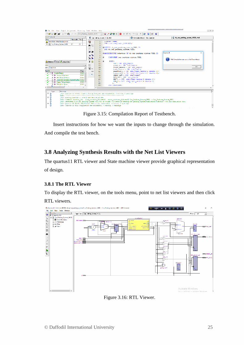
Figure 3.15: Compilation Report of Testbench.
Insert instructions for how we want the inputs to change through the simulation.
And compile the test bench.
3.8 Analyzing Synthesis Results with the Net List Viewers
The quartus11 RTL viewer and State machine viewer provide graphical representation
of design.
3.8.1 The RTL Viewer
To display the RTL viewer, on the tools menu, point to net list viewers and then click
RTL viewers.
Figure 3.16: RTL Viewer.
© Daffodil International University 26
The RTL viewer displays the analysis and elaborations results for VHDL design.
Our RTL design consist of above information.
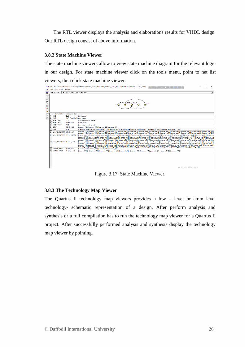
3.8.2 State Machine Viewer
The state machine viewers allow to view state machine diagram for the relevant logic
in our design. For state machine viewer click on the tools menu, point to net list
viewers, then click state machine viewer.
Figure 3.17: State Machine Viewer.
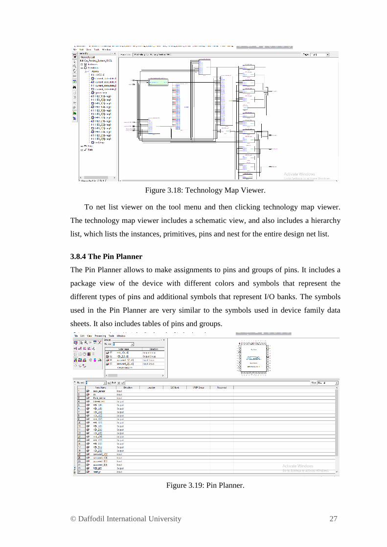
3.8.3 The Technology Map Viewer
The Quartus II technology map viewers provides a low – level or atom level
technology- schematic representation of a design. After perform analysis and
synthesis or a full compilation has to run the technology map viewer for a Quartus II
project. After successfully performed analysis and synthesis display the technology
map viewer by pointing.
© Daffodil International University 27
Figure 3.18: Technology Map Viewer.
To net list viewer on the tool menu and then clicking technology map viewer.
The technology map viewer includes a schematic view, and also includes a hierarchy
list, which lists the instances, primitives, pins and nest for the entire design net list.
3.8.4 The Pin Planner
The Pin Planner allows to make assignments to pins and groups of pins. It includes a
package view of the device with different colors and symbols that represent the
different types of pins and additional symbols that represent I/O banks. The symbols
used in the Pin Planner are very similar to the symbols used in device family data
sheets. It also includes tables of pins and groups.
Figure 3.19: Pin Planner.

© Daffodil International University 28
From the pin planner a groups list, and all pins list and a package view diagram
of the device can be displayed. By dragging pins from the groups list and all pins list
to an available pin or I/O bank locations in the package diagram can be made pin
assignments. From the all pins list can filter the node names, change the I/O
standards, and specify options for reserved pins. Can also filter the all pins list to
display on the unassigned pins, so it can be changed the node name and direction for
user added nodes. Reserved pins options can also be specified.
3.9 Hardware Components
We've utilized the accompanying hardware segments for our project:
Altera FPGA Board
Sensor
LED Display
H-Bridge
Relay
Power Supply
3.9.1 Altera FPGA Board
A field-programmable gate array (FPGA) is an integrated circuit and is fabricated to
be effortlessly reconfigured by engineers, fashioners or clients. FPGAs are logical
blocks and interconnects that can be programmable by Hardware Description
Languages (Verilog HDL/VHDL) to perform distinctive complex capacities. FPGA
boards as pursues:
1. Xilinx FPGA board
2. Altera FPGA board
Here we utilized Altera FPGA board in this project. This board is comprises of
single LED, 7-segment LED, IOs for LCD. On board PS/2, VGA, RS232 port for
UART communications. Offer example code and programming record to test.
© Daffodil International University 29
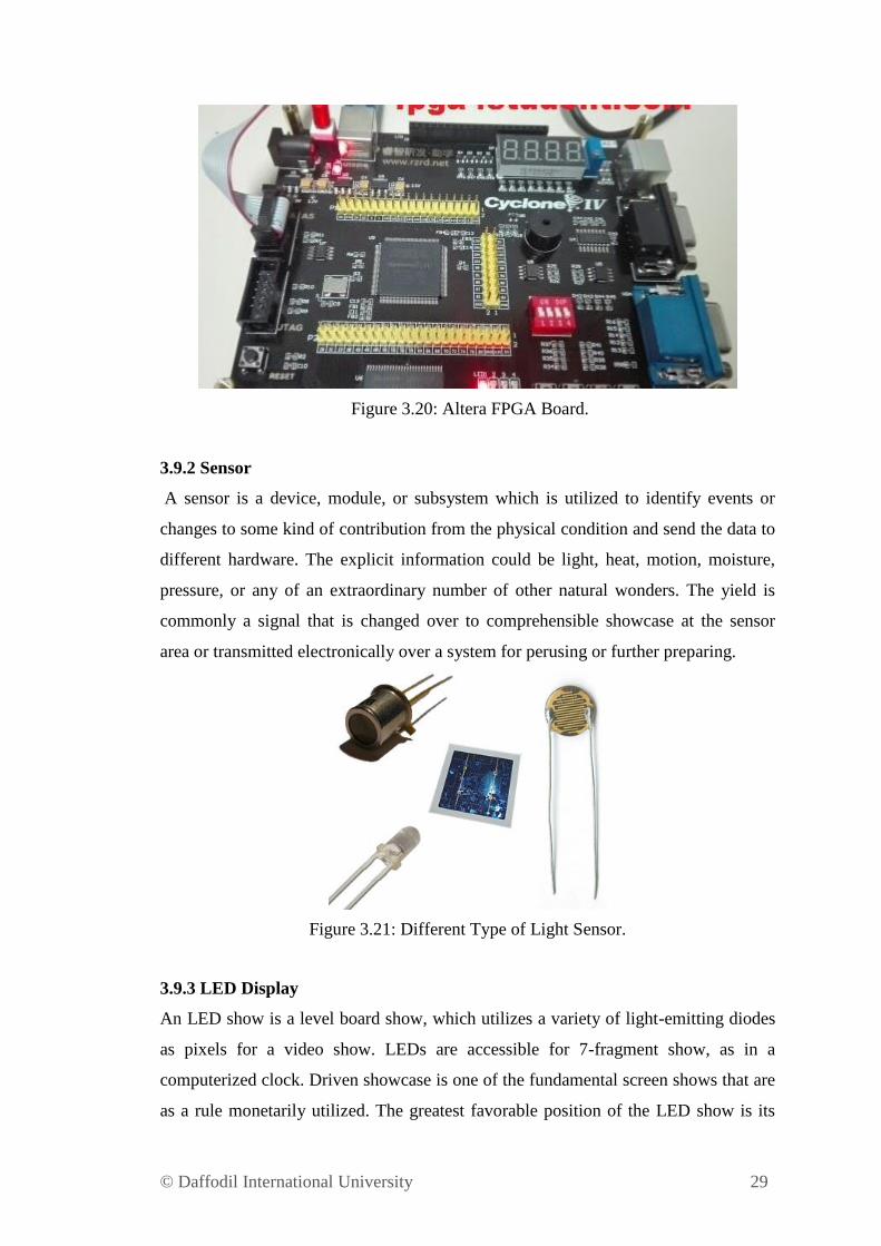
Figure 3.20: Altera FPGA Board.
3.9.2 Sensor
A sensor is a device, module, or subsystem which is utilized to identify events or
changes to some kind of contribution from the physical condition and send the data to
different hardware. The explicit information could be light, heat, motion, moisture,
pressure, or any of an extraordinary number of other natural wonders. The yield is
commonly a signal that is changed over to comprehensible showcase at the sensor
area or transmitted electronically over a system for perusing or further preparing.
Figure 3.21: Different Type of Light Sensor.
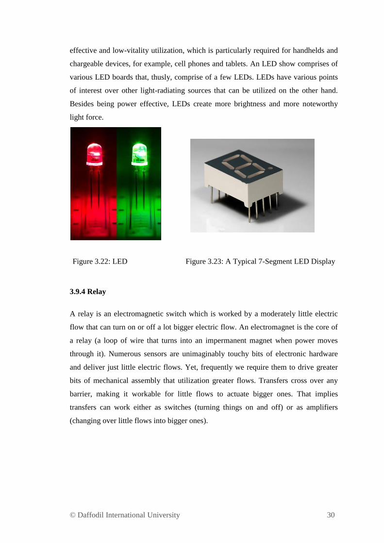
3.9.3 LED Display
An LED show is a level board show, which utilizes a variety of light-emitting diodes
as pixels for a video show. LEDs are accessible for 7-fragment show, as in a
computerized clock. Driven showcase is one of the fundamental screen shows that are
as a rule monetarily utilized. The greatest favorable position of the LED show is its
© Daffodil International University 30
effective and low-vitality utilization, which is particularly required for handhelds and
chargeable devices, for example, cell phones and tablets. An LED show comprises of
various LED boards that, thusly, comprise of a few LEDs. LEDs have various points
of interest over other light-radiating sources that can be utilized on the other hand.
Besides being power effective, LEDs create more brightness and more noteworthy
light force.
Figure 3.22: LED Figure 3.23: A Typical 7-Segment LED Display
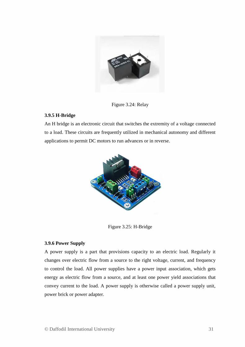
3.9.4 Relay
A relay is an electromagnetic switch which is worked by a moderately little electric
flow that can turn on or off a lot bigger electric flow. An electromagnet is the core of
a relay (a loop of wire that turns into an impermanent magnet when power moves
through it). Numerous sensors are unimaginably touchy bits of electronic hardware
and deliver just little electric flows. Yet, frequently we require them to drive greater
bits of mechanical assembly that utilization greater flows. Transfers cross over any
barrier, making it workable for little flows to actuate bigger ones. That implies
transfers can work either as switches (turning things on and off) or as amplifiers
(changing over little flows into bigger ones).
© Daffodil International University 31
Figure 3.24: Relay
3.9.5 H-Bridge
An H bridge is an electronic circuit that switches the extremity of a voltage connected
to a load. These circuits are frequently utilized in mechanical autonomy and different
applications to permit DC motors to run advances or in reverse.
Figure 3.25: H-Bridge
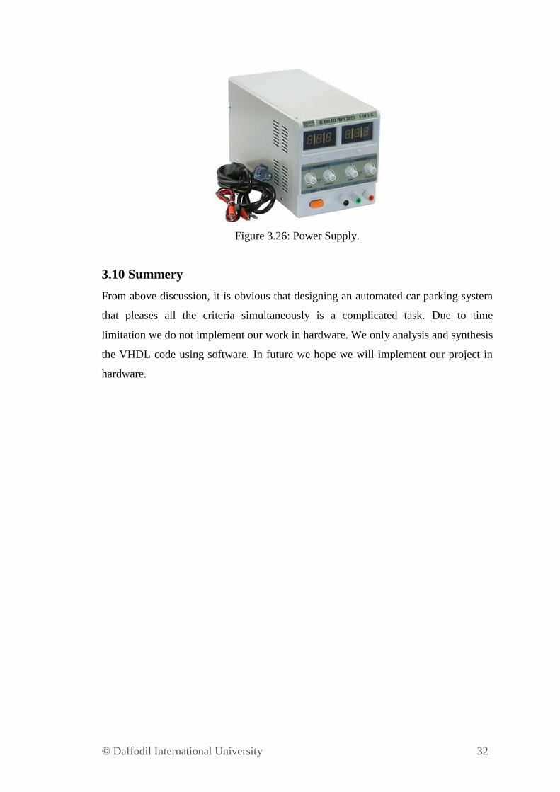
3.9.6 Power Supply
A power supply is a part that provisions capacity to an electric load. Regularly it
changes over electric flow from a source to the right voltage, current, and frequency
to control the load. All power supplies have a power input association, which gets
energy as electric flow from a source, and at least one power yield associations that
convey current to the load. A power supply is otherwise called a power supply unit,
power brick or power adapter.
© Daffodil International University 32
Figure 3.26: Power Supply.
3.10 Summery
From above discussion, it is obvious that designing an automated car parking system
that pleases all the criteria simultaneously is a complicated task. Due to time
limitation we do not implement our work in hardware. We only analysis and synthesis
the VHDL code using software. In future we hope we will implement our project in
hardware.
© Daffodil International University 33
CHAPTER 4
RESULTS AND DISCUSSION
4.1 Introduction
In this chapter we will simulate our VHDL program using Vector Waveform File in
Quartus II Software. The result for simulation will be detailed in this chapter. The
output simulation result will also be shown in this chapter.
4.2 Result for Automated Car Parking System
After compilation the VHDL code we can generate waveform from the code. From
the wave we will know about our exertion is working or not. We add input output pins
in the wave as shown as below.
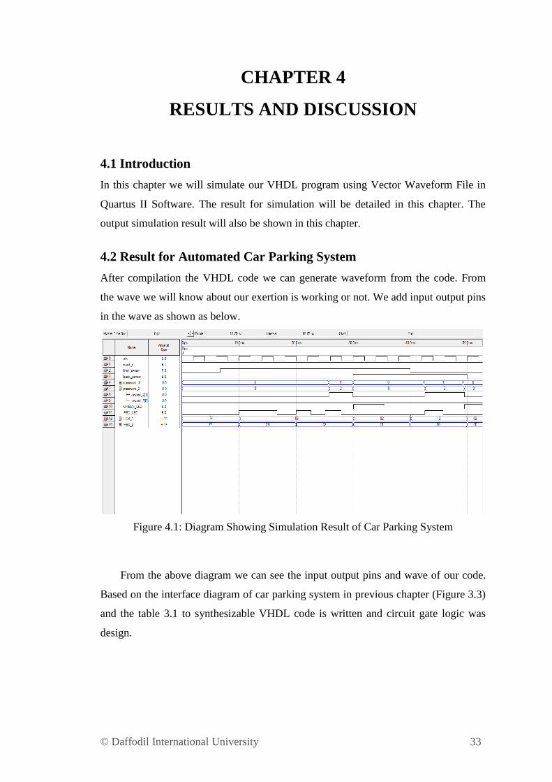
Figure 4.1: Diagram Showing Simulation Result of Car Parking System
From the above diagram we can see the input output pins and wave of our code.
Based on the interface diagram of car parking system in previous chapter (Figure 3.3)
and the table 3.1 to synthesizable VHDL code is written and circuit gate logic was
design.
© Daffodil International University 34
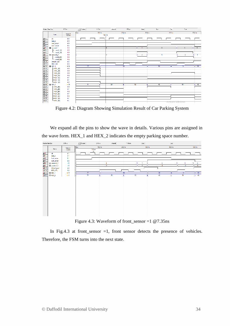
Figure 4.2: Diagram Showing Simulation Result of Car Parking System
We expand all the pins to show the wave in details. Various pins are assigned in
the wave form. HEX_1 and HEX_2 indicates the empty parking space number.
Figure 4.3: Waveform of front_sensor =1 @7.35ns
In Fig.4.3 at front_sensor =1, front sensor detects the presence of vehicles.
Therefore, the FSM turns into the next state.
© Daffodil International University 35
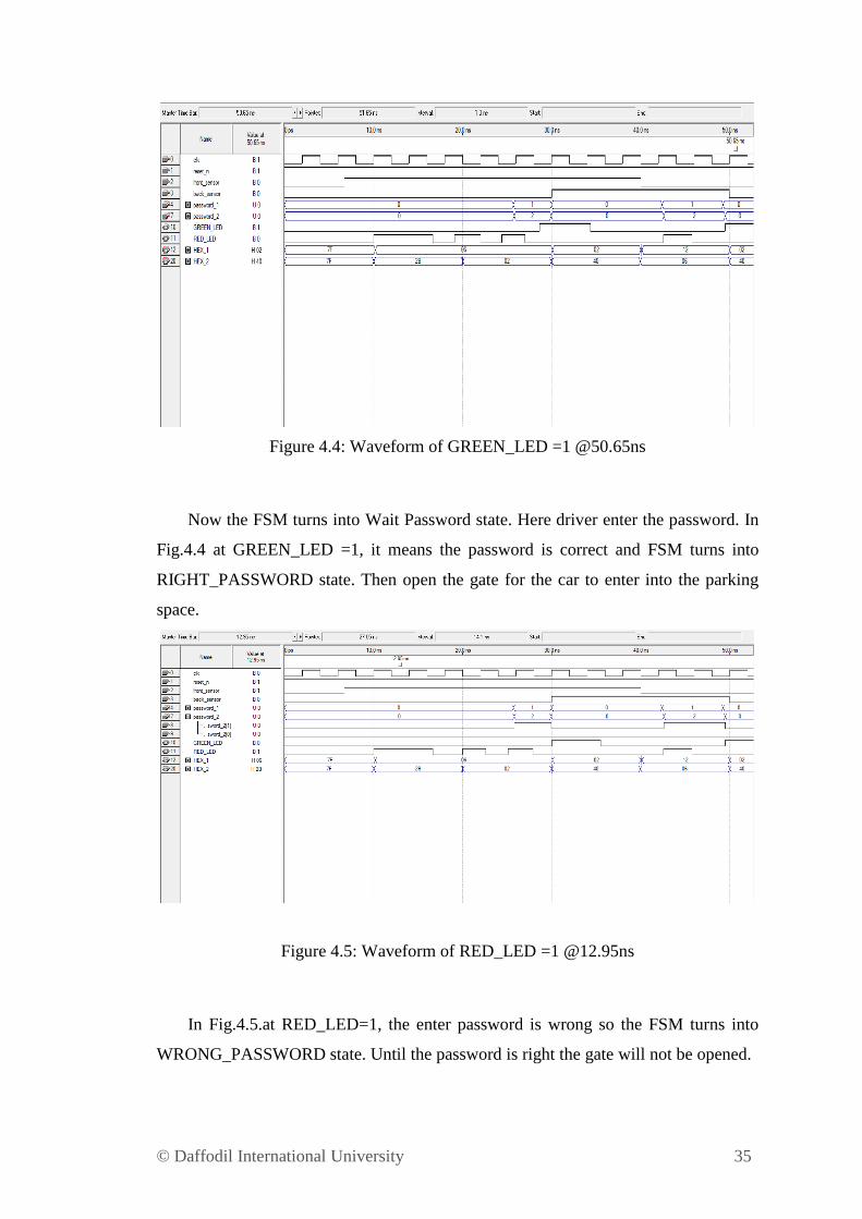
Figure 4.4: Waveform of GREEN_LED =1 @50.65ns
Now the FSM turns into Wait Password state. Here driver enter the password. In
Fig.4.4 at GREEN_LED =1, it means the password is correct and FSM turns into
RIGHT_PASSWORD state. Then open the gate for the car to enter into the parking
space.
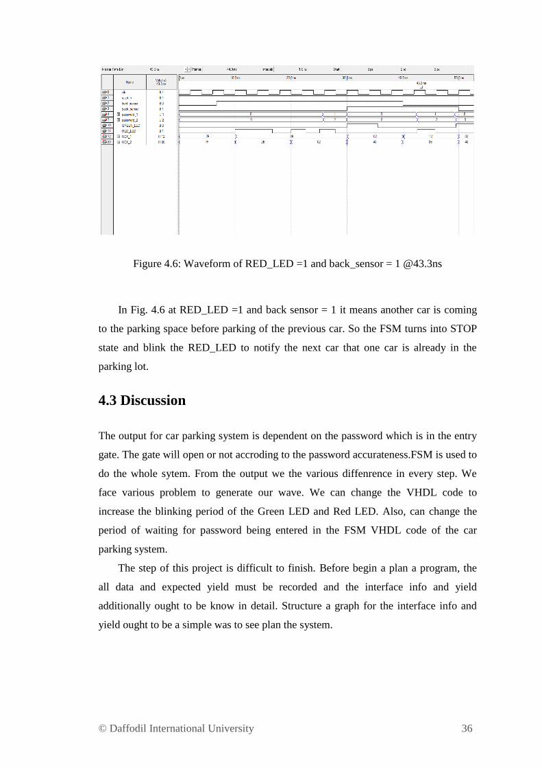
Figure 4.5: Waveform of RED_LED =1 @12.95ns
In Fig.4.5.at RED_LED=1, the enter password is wrong so the FSM turns into
WRONG_PASSWORD state. Until the password is right the gate will not be opened.
© Daffodil International University 36
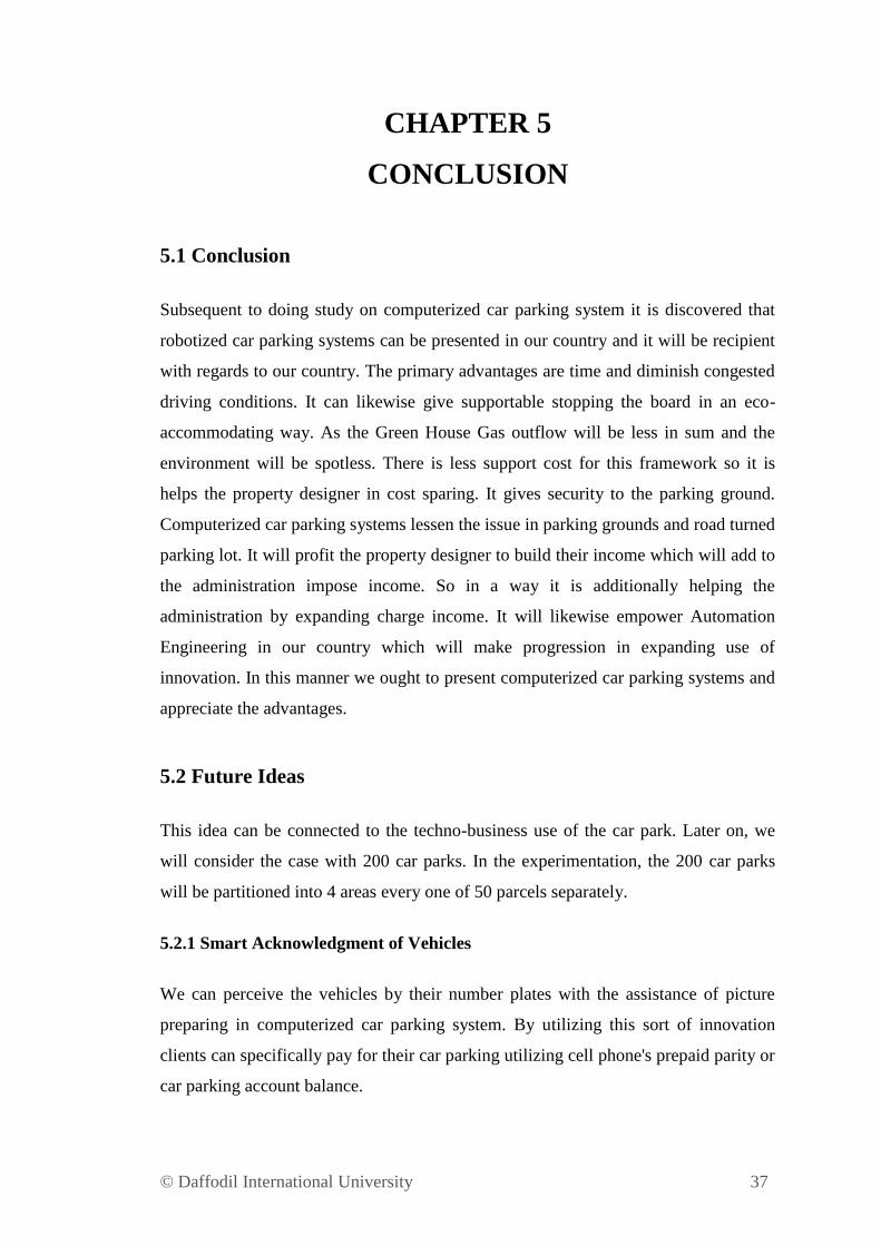
Figure 4.6: Waveform of RED_LED =1 and back_sensor = 1 @43.3ns
In Fig. 4.6 at RED_LED =1 and back sensor = 1 it means another car is coming
to the parking space before parking of the previous car. So the FSM turns into STOP
state and blink the RED_LED to notify the next car that one car is already in the
parking lot.
4.3 Discussion
The output for car parking system is dependent on the password which is in the entry
gate. The gate will open or not accroding to the password accurateness.FSM is used to
do the whole sytem. From the output we the various diffenrence in every step. We
face various problem to generate our wave. We can change the VHDL code to
increase the blinking period of the Green LED and Red LED. Also, can change the
period of waiting for password being entered in the FSM VHDL code of the car
parking system.
The step of this project is difficult to finish. Before begin a plan a program, the
all data and expected yield must be recorded and the interface info and yield
additionally ought to be know in detail. Structure a graph for the interface info and
yield ought to be a simple was to see plan the system.
© Daffodil International University 37
CHAPTER 5
CONCLUSION
5.1 Conclusion
Subsequent to doing study on computerized car parking system it is discovered that
robotized car parking systems can be presented in our country and it will be recipient
with regards to our country. The primary advantages are time and diminish congested
driving conditions. It can likewise give supportable stopping the board in an eco-
accommodating way. As the Green House Gas outflow will be less in sum and the
environment will be spotless. There is less support cost for this framework so it is
helps the property designer in cost sparing. It gives security to the parking ground.
Computerized car parking systems lessen the issue in parking grounds and road turned
parking lot. It will profit the property designer to build their income which will add to
the administration impose income. So in a way it is additionally helping the
administration by expanding charge income. It will likewise empower Automation
Engineering in our country which will make progression in expanding use of
innovation. In this manner we ought to present computerized car parking systems and
appreciate the advantages.
5.2 Future Ideas
This idea can be connected to the techno-business use of the car park. Later on, we
will consider the case with 200 car parks. In the experimentation, the 200 car parks
will be partitioned into 4 areas every one of 50 parcels separately.
5.2.1 Smart Acknowledgment of Vehicles
We can perceive the vehicles by their number plates with the assistance of picture
preparing in computerized car parking system. By utilizing this sort of innovation
clients can specifically pay for their car parking utilizing cell phone's prepaid parity or
car parking account balance.
© Daffodil International University 38
5.2.2 Updating Users About Accessible Slots and Record Balance
Client can get refreshes about accessible slots of a specific parking spot and record
balance by sending a basic SMS to the information base.
5.3 Commercialization Potential
The purposes of this project are to design a safe and efficient parking space and to
assign the right way to minimize delay waiting time to park car. This project, a car
parking system is to improve the movement of the vehicles on the parking space. This
project is design to remove the unplanned car park on the road.
The intelligent car parking system was chosen because to practice designing a
program. When using this product, it will be able to reduce a traffic jam in road,
ensure car safety and it also to minimize a waiting time to park car.
I believe that my product is very brilliant idea to solve a parking problem. This is
because almost of the car parking system in city using a manual parking system.
In the market, there are has similar idea with my project. The automatic system is
not widely used in Dhaka. This product actually designs for Dhaka to solve the
parking problem.
This product is not expensive compare with the other product. It product can uses
in anywhere. This product not only can use in Dhaka, it also can use for the other city.
© Daffodil International University 39
REFERENCES
1. Ramneet Kaur and Balwinder Singh (2013) “DESIGN AND
IMPLEMENTATION OF CAR PARKING SYSTEM ON FPGA”.
2. www.altera.com.
3. Vanessa W.S. Tang, Yuan Zheng and Jiannong Cao, “An intelligent car
management system based on wireless sensor networks”
4. Mala Aggarwal, Simmi Aggarwal and R.S. Uppal, “Comparative
implementation of automatic car parking system with least distance parking
space in wireless sensor networks”.
5. Maria Rodriguez Ferandez, Eduardo Zalama Casanova and Ignacio Gonzalez
Alonso “Review of Display Technologies Focusing on Power Consumption”
6. Insop Song; Gowan, K.; Nery, J.; Han, H.; Sheng, T.; Li, H.; Karray, F.;
,(2006) "Intelligent Parking System Design Using FPGA," Field
Programmable Logic and Applications,
7. Srikanth, S.V.; Pramod, P.J.; Dileep, K.P.; Tapas, S.; Patil, M.U.; Sarat,
C.B.N.;(2009) , "Design and Implementation of a Prototype Smart Parking
(SPARK) System Using Wireless Sensor Networks."
8. www.fpga4student.com
© Daffodil International University 40
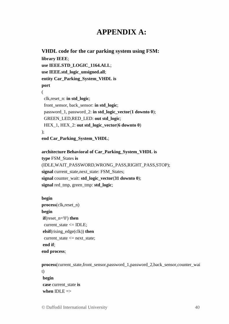
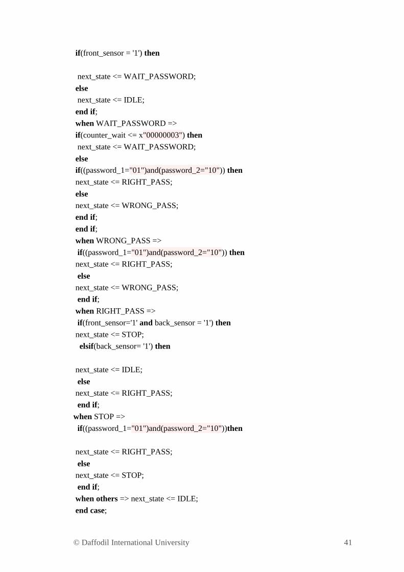
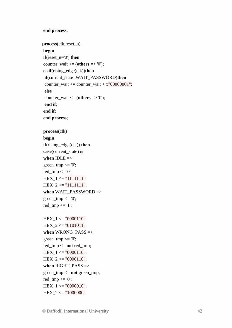
APPENDIX A:
VHDL code for the car parking system using FSM:
library IEEE;
use IEEE.STD_LOGIC_1164.ALL;
use IEEE.std_logic_unsigned.all;
entity Car_Parking_System_VHDL is
port
(
clk,reset_n: in std_logic;
front_sensor, back_sensor: in std_logic;
password_1, password_2: in std_logic_vector(1 downto 0);
GREEN_LED,RED_LED: out std_logic;
HEX_1, HEX_2: out std_logic_vector(6 downto 0)
);
end Car_Parking_System_VHDL;
architecture Behavioral of Car_Parking_System_VHDL is
type FSM_States is
(IDLE,WAIT_PASSWORD,WRONG_PASS,RIGHT_PASS,STOP);
signal current_state,next_state: FSM_States;
signal counter_wait: std_logic_vector(31 downto 0);
signal red_tmp, green_tmp: std_logic;
begin
process(clk,reset_n)
begin
if(reset_n='0') then
current_state <= IDLE;
elsif(rising_edge(clk)) then
current_state <= next_state;
end if;
end process;
process(current_state,front_sensor,password_1,password_2,back_sensor,counter_wai
t)
begin
case current_state is
when IDLE =>
© Daffodil International University 41
if(front_sensor = '1') then
next_state <= WAIT_PASSWORD;
else
next_state <= IDLE;
end if;
when WAIT_PASSWORD =>
if(counter_wait <= x"00000003") then
next_state <= WAIT_PASSWORD;
else
if((password_1="01")and(password_2="10")) then
next_state <= RIGHT_PASS;
else
next_state <= WRONG_PASS;
end if;
end if;
when WRONG_PASS =>
if((password_1="01")and(password_2="10")) then
next_state <= RIGHT_PASS;
else
next_state <= WRONG_PASS;
end if;
when RIGHT_PASS =>
if(front_sensor='1' and back_sensor = '1') then
next_state <= STOP;
elsif(back_sensor= '1') then
next_state <= IDLE;
else
next_state <= RIGHT_PASS;
end if;
when STOP =>
if((password_1="01")and(password_2="10"))then
next_state <= RIGHT_PASS;
else
next_state <= STOP;
end if;
when others => next_state <= IDLE;
end case;
© Daffodil International University 42
end process;
process(clk,reset_n)
begin
if(reset_n='0') then
counter_wait <= (others => '0');
elsif(rising_edge(clk))then
if(current_state=WAIT_PASSWORD)then
counter_wait <= counter_wait + x"00000001";
else
counter_wait <= (others => '0');
end if;
end if;
end process;
process(clk)
begin
if(rising_edge(clk)) then
case(current_state) is
when IDLE =>
green_tmp <= '0';
red_tmp <= '0';
HEX_1 <= "1111111";
HEX_2 <= "1111111";
when WAIT_PASSWORD =>
green_tmp <= '0';
red_tmp <= '1';
HEX_1 <= "0000110";
HEX_2 <= "0101011";
when WRONG_PASS =>
green_tmp <= '0';
red_tmp <= not red_tmp;
HEX_1 <= "0000110";
HEX_2 <= "0000110";
when RIGHT_PASS =>
green_tmp <= not green_tmp;
red_tmp <= '0';
HEX_1 <= "0000010";
HEX_2 <= "1000000";
© Daffodil International University 43
when STOP =>
green_tmp <= '0';
red_tmp <= not red_tmp;
HEX_1 <= "0010010";
HEX_2 <= "0001100";
when others =>
green_tmp <= '0';
red_tmp <= '0';
HEX_1 <= "1111111";
HEX_2 <= "1111111";
end case;
end if;
end process;
RED_LED <= red_tmp;
GREEN_LED <= green_tmp;
end Behavioral;
© Daffodil International University 44
APPENDIX B:
VHDL Testbench code for the car parking system using FSM:
LIBRARY ieee;
USE ieee.std_logic_1164.ALL;
ENTITY tb_car_parking_system_VHDL IS
END tb_car_parking_system_VHDL;
ARCHITECTURE behavior OF tb_car_parking_system_VHDL IS
COMPONENT Car_Parking_System_VHDL
PORT(
clk : IN std_logic;
reset_n : IN std_logic;
front_sensor : IN std_logic;
back_sensor : IN std_logic;
password_1 : IN std_logic_vector(1 downto 0);
password_2 : IN std_logic_vector(1 downto 0);
GREEN_LED : OUT std_logic;
RED_LED : OUT std_logic;
HEX_1 : OUT std_logic_vector(6 downto 0);
HEX_2 : OUT std_logic_vector(6 downto 0)
);
END COMPONENT;
signal clk : std_logic := '0';
signal reset_n : std_logic := '0';
signal front_sensor : std_logic := '0';
signal back_sensor : std_logic := '0';
signal password_1 : std_logic_vector(1 downto 0) := (others => '0');
signal password_2 : std_logic_vector(1 downto 0) := (others => '0');
signal GREEN_LED : std_logic;
signal RED_LED : std_logic;
signal HEX_1 : std_logic_vector(6 downto 0);
signal HEX_2 : std_logic_vector(6 downto 0);
© Daffodil International University 45
constant clk_period : time := 10 ns;
BEGIN
Car_park_system: Car_Parking_System_VHDL PORT MAP (
clk => clk,
reset_n => reset_n,
front_sensor => front_sensor,
back_sensor => back_sensor,
password_1 => password_1,
password_2 => password_2,
GREEN_LED => GREEN_LED,
RED_LED => RED_LED,
HEX_1 => HEX_1,
HEX_2 => HEX_2);
clk_process :process
begin
clk <= '0';
wait for clk_period/2;
clk <= '1';
wait for clk_period/2;
end process;
stim_proc: process
begin
reset_n <= '0';
front_sensor <= '0';
back_sensor <= '0';
password_1 <= "00";
password_2 <= "00";
wait for clk_period*10;
reset_n <= '1';
wait for clk_period*10;
front_sensor <= '1';
© Daffodil International University 46
wait for clk_period*10;
password_1 <= "01";
password_2 <= "10";
wait until HEX_1 = "0000010";
password_1 <= "00";
password_2 <= "00";
back_sensor <= '1';
wait until HEX_1 = "0010010";
password_1 <= "01";
password_2 <= "10";
front_sensor <= '0';
wait until HEX_1 = "0000010";
password_1 <= "00";
password_2 <= "00";
back_sensor <= '1';
wait until HEX_1 = "1111111";
back_sensor <= '0';
wait;
end process;
END;