caravan mover user`s manual · pdf file1 per side 17 extention tube 2 6 ... single or twin...
TRANSCRIPT
Model 2012 issue v.1.1
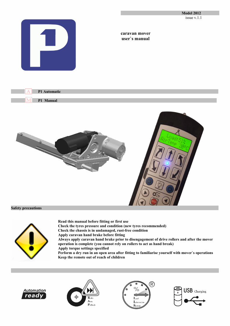
caravan mover user`s manual
P1 Automatic
P1 Manual
Safety precautions
Read this manual before fitting or first useCheck the tyres pressure and condition (new tyres recommended)Check the chassis is in undamaged, rust-free conditionApply caravan hand brake before fittingAlways apply caravan hand brake prior to disengagement of drive rollers and after the mover operation is complete (you cannot rely on rollers to act as hand break)Apply torque settings specifiedPerform a dry run in an open area after fitting to familiarise yourself with mover`s operationsKeep the remote out of reach of children
What`s inside the boxes
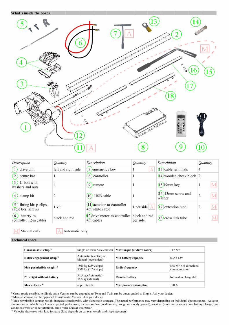
Description Quantity Description Quantity Description Quantity
1 drive unit left and right side 7 emergency key 1 13 cable terminals 4
2 centre bar 1 8 controller 1 14 wooden check block 2
3 U-bolt with washers and nuts 4 9 remote 1 15 19mm key 1
4 clamp kit 2 10 USB cable 1 16 13mm screw and washer 2
5 fitting kit: p-clips, cable ties, screws 1 kit 11 actuator-to-controller
4m white cable 1 per side 17 extention tube 2
6 battery-to-controller 1.5m cables black and red 12 drive motor-to-controller
4m cablesblack and red per side 18 cross link tube 1
Manual only P1 Automatic only
Technical specs
Caravan axle setup 1) Single or Twin Axle caravan Max torque (at drive roller) 117 Nm
Roller engagement setup 2) Automatic (electric) or Manual (mechanical) Min battery capacity 80Ah 12V
Max permissible weight 3) 1800 kg (25% slope)3000 kg (10% slope) Radio frequency 868 MHz bi-directional
communication
P1 weight without battery 34.5 kg (Automatic)36.5 kg (Manual) Remote battery Internal, rechargeable
Max velocity 4) appr. 14cm/s Max power consumption 120 A
1) Cross-grade possible, ie. Single Axle Version can be upgraded to Twin and Twin can be down-graded to Single. Ask your dealer.2) Manual Version can be upgraded to Automatic Version. Ask your dealer.3) Max permissible caravan weight increases considerably with slope ratio decrease. The actual performance may vary depending on individual circumstances. Adverse circumstances, which may lower expected performace, include surface condition (eg. rough or muddy ground), weather (moisture or snow), low battery charge, tyre condition (wear or underinflation), drive roller normal wear&tear. 4) Velocity decreases with load increase (load depends on caravan weight and slope steepness)
Chassis critical dimentions
Standard kit allows fitting to vast majority of caravans available (will fit both L-plate type and U-plate type chassis).
If in any doubt please check that the chassis of your caravan complies with the standard dimentions as shown besides.
For non-standard caravans special adapters are available – check with your dealer.
Tools needed
− open-end or ring 10 mm wrench: 2 No− open-end or ring 13 mm wrench: 2 No− open-end or ring 17 mm wrench: 1 No− small pozi/cross screwdriver− torque wrench− 6mm2 cable crimper
Mechanical assembly order
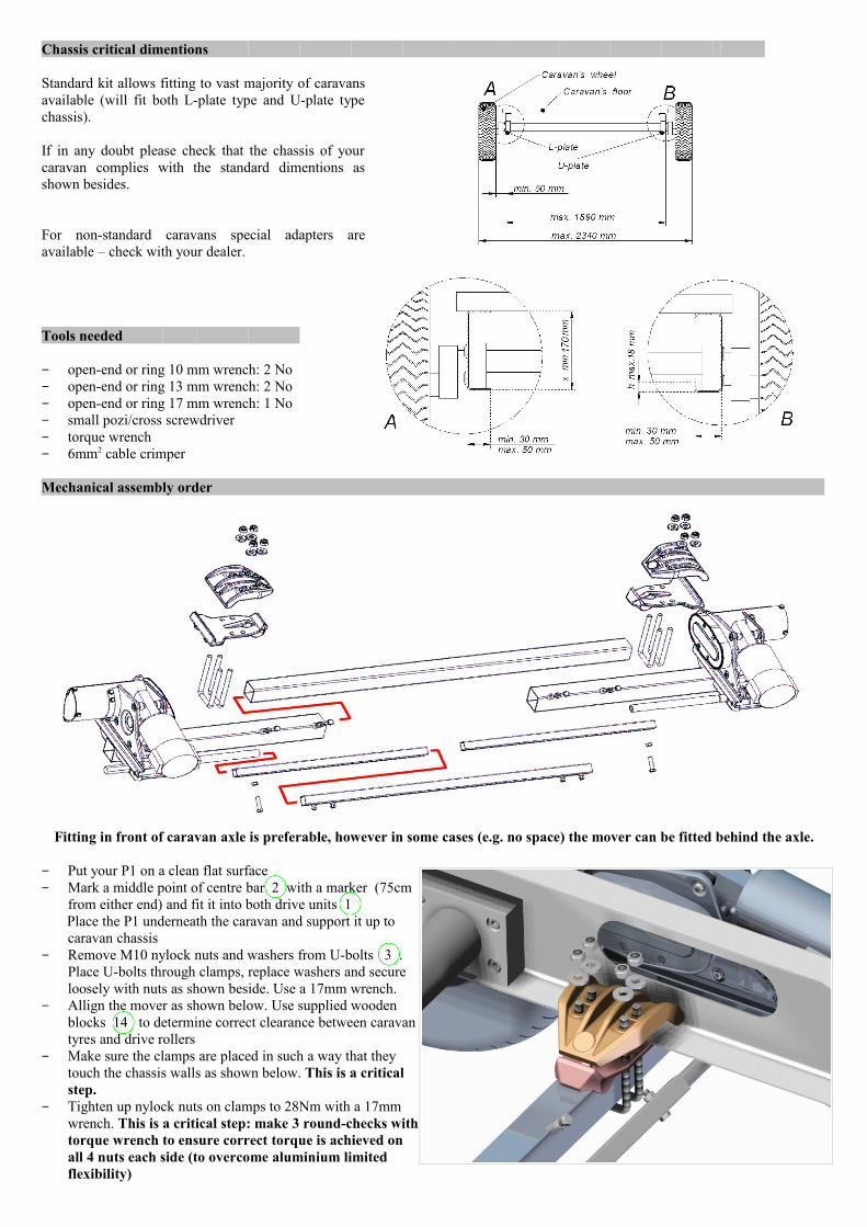
Fitting in front of caravan axle is preferable, however in some cases (e.g. no space) the mover can be fitted behind the axle.
− Put your P1 on a clean flat surface− Mark a middle point of centre bar 2 with a marker (75cm
from either end) and fit it into both drive units 1 Place the P1 underneath the caravan and support it up to
caravan chassis− Remove M10 nylock nuts and washers from U-bolts 3 .
Place U-bolts through clamps, replace washers and secure loosely with nuts as shown beside. Use a 17mm wrench.
− Allign the mover as shown below. Use supplied wooden blocks 14 to determine correct clearance between caravan tyres and drive rollers
− Make sure the clamps are placed in such a way that they touch the chassis walls as shown below. This is a critical step.
− Tighten up nylock nuts on clamps to 28Nm with a 17mm wrench. This is a critical step: make 3 round-checks with torque wrench to ensure correct torque is achieved on all 4 nuts each side (to overcome aluminium limited flexibility)
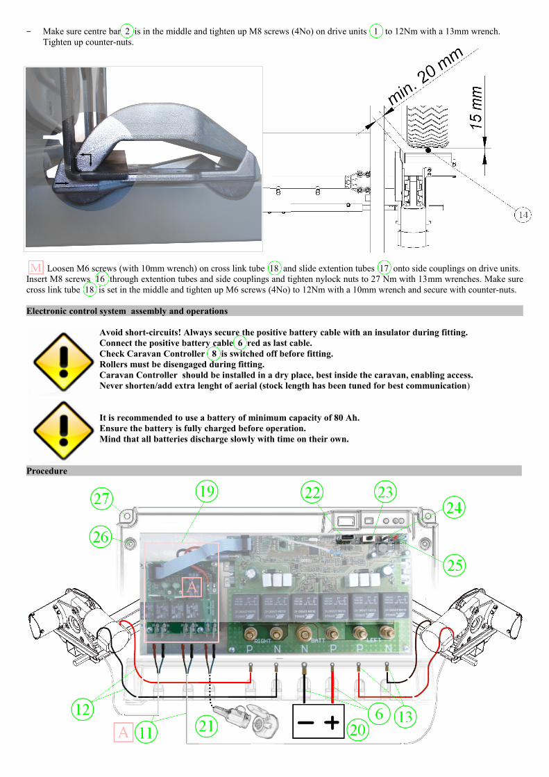
− Make sure centre bar 2 is in the middle and tighten up M8 screws (4No) on drive units 1 to 12Nm with a 13mm wrench. Tighten up counter-nuts.
Loosen M6 screws (with 10mm wrench) on cross link tube 18 and slide extention tubes 17 onto side couplings on drive units. Insert M8 screws 16 through extention tubes and side couplings and tighten nylock nuts to 27 Nm with 13mm wrenches. Make sure cross link tube 18 is set in the middle and tighten up M6 screws (4No) to 12Nm with a 10mm wrench and secure with counter-nuts.
Electronic control system assembly and operations
Avoid short-circuits! Always secure the positive battery cable with an insulator during fitting. Connect the positive battery cable 6 red as last cable. Check Caravan Controller 8 is switched off before fitting. Rollers must be disengaged during fitting.Caravan Controller should be installed in a dry place, best inside the caravan, enabling access.Never shorten/add extra lenght of aerial (stock length has been tuned for best communication)
It is recommended to use a battery of minimum capacity of 80 Ah. Ensure the battery is fully charged before operation. Mind that all batteries discharge slowly with time on their own.
Procedure
− choose a dry place for Controller 8 to be installed having cables length in mind. Front boot or inside of the caravan at floor level (eg. under bed) is recommended.
− lead cables from left/right motors 12 and the battery 6 ( and actuators 11 ) to the area where Controller will be installed. Drill a hole (ID 14mm) in caravan floor if necessary (be carefull not to damage installation that may be running under or over the floor; instead of cutting cables to length we recommend leaving the original length and securing the excess with cable ties (in case of transfering the mover to your next – bigger caravan you may need longer cables)
− terminate cables 12 with cable terminals 13
Ensure cables do not chaff especially when led through caravan`s floor (use protective grommet, tape, tube sleeve or the like if necessary – not supplied). Use p-clips and cable ties to secure cables to underneath the caravan floor. Leave a length of slack cable by drive motors to allow for rollers` engagement/disengagement movement.Red colour cables denote positive (+) polarity.
− secure Controller 8 in place with screws (supplied) using lug holes 27 . Undo 4 screws 26 on top of Controller and remove lid carefully.
− Remove brass nuts and upper washers inside Controller and connect motor cables 12 to respective terminals (red cable to „P” terminal and black cable to „N”). Connect battery cables 6 in the same fashion. Replace washers and tighten nuts to 8Nm.
If P1 mover is fitted behind the caravan axle(s) polarity of motor cables 12 must be reversed, ie. black cables connect to „P” (positive) terminals and red cables connect to „N” (negative) terminals on 8 .
− connect actuator cables 11 to Roller Control Board 19 (comes pre-fitted on Automatic Model)− connect Towbar terminals 21 to appropriate pins in caravan plug („N” to ground (-) and „P” to permanent 12V DC (+)
supply). Use 2x1mm2 cable terminated with spade connectors (not supplied). Check if your caravan plug allows such connection beforehand (most 13-pin Euro plugs do). Terminals are protected against reversed polarity.
− terminate the other ends of battery cables 6 with good quality battery clamps (not supplied)− connect battery cables 6 to battery 20 . − Switch the system On and check operations of the mover by observing rollers movement (double-check the rollers are disengaged
beforehand). check operation of IN/OUT movement of the rollers.− Replace lid and tighten the 4 screws on Caravan Controller 8
Remote control operating manual
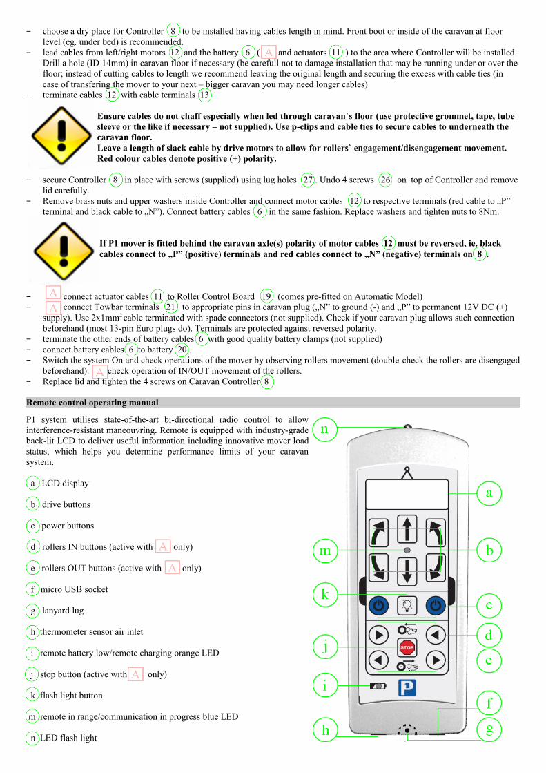
P1 system utilises state-of-the-art bi-directional radio control to allow interference-resistant maneouvring. Remote is equipped with industry-grade back-lit LCD to deliver useful information including innovative mover load status, which helps you determine performance limits of your caravan system.
a LCD display
b drive buttons
c power buttons
d rollers IN buttons (active with only)
e rollers OUT buttons (active with only)
f micro USB socket
g lanyard lug
h thermometer sensor air inlet
i remote battery low/remote charging orange LED
j stop button (active with only)
k flash light button
m remote in range/communication in progress blue LED n LED flash light
Switching ON/OFF
To activate the system Switch ON power switch 23 on the controller 8 . Green LED 25 blinks for 2 sec (internal self-test). Continuous green LED illumination denotes system ready to work. Green LED flashes fast when receiving signal from the Remote.
To switch Remote ON press simultaneously both c buttons for 2 sec. Remote switches OFF after 20sec if Controller signal cannot be found or, when connected, if no button has been pressed for 1 min. LCD info Description ConnectingAirTemp 22°C
Remote searching for signal. Blue LED m flashes. Stays lit up when in connection. Flashes fast when sending or receiving command. If Remote can`t connect within 3sec distance may be too long or Controller is switched OFF.
Drive rollers engagement/disengagement
To engage drive rollers use 19mm key 15 and turn protruding hexagonal shaft (on either side of the caravan) in a circular decided swing towards the tyre. Both rollers will engage simultaneously .
To disengage drive rollers turn protruding hexagonal shaft (on either side of the caravan) in a circular decided reverse swing out of the tyre. Both rollers will disengage simultaneously .
ALWAYS apply caravan handbrake before disengaging rollers
Drive rollers engagement/disengagement
LCD info Description >> ● <<AirTemp 22°C
Engagement of rollers. Press (and release) both d buttons to move rollers IN to the tyres. Rollers will stop as soon as correct individual pressure on tyre is achieved (useful if caravan tyres are not pressurised identically).
<< ● >>AirTemp 22°C
Disengagement of rollers. Press (and release) both e buttons to move rollers OUT of the tyres.
STOP ● STOPAirTemp 22°C
Emergency Stop button activated. Press STOP button j to interrupt engagement/disengagement process (e.g in case of emergency). Engagement/disengagement of rollers may be continued after 3sec.
ALWAYS apply caravan handbrake before disengaging rollers
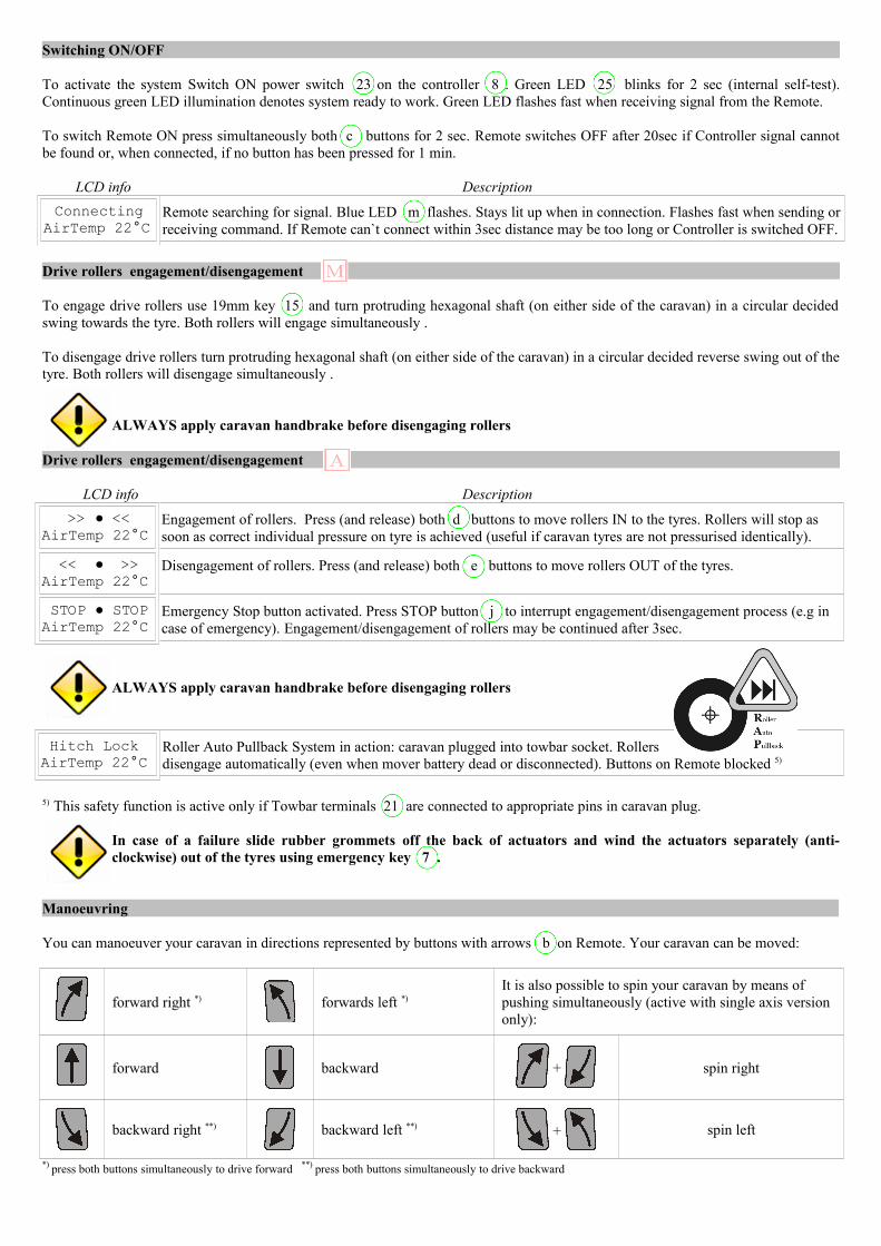
Hitch LockAirTemp 22°C
Roller Auto Pullback System in action: caravan plugged into towbar socket. Rollers disengage automatically (even when mover battery dead or disconnected). Buttons on Remote blocked 5)
5) This safety function is active only if Towbar terminals 21 are connected to appropriate pins in caravan plug.
In case of a failure slide rubber grommets off the back of actuators and wind the actuators separately (anti-clockwise) out of the tyres using emergency key 7 .
Manoeuvring
You can manoeuver your caravan in directions represented by buttons with arrows b on Remote. Your caravan can be moved:
forward right *) forwards left *)It is also possible to spin your caravan by means of pushing simultaneously (active with single axis version only):
forward backward + spin right
backward right **) backward left **) + spin left
*) press both buttons simultaneously to drive forward **) press both buttons simultaneously to drive backward
Mover Load Information System (LIS)
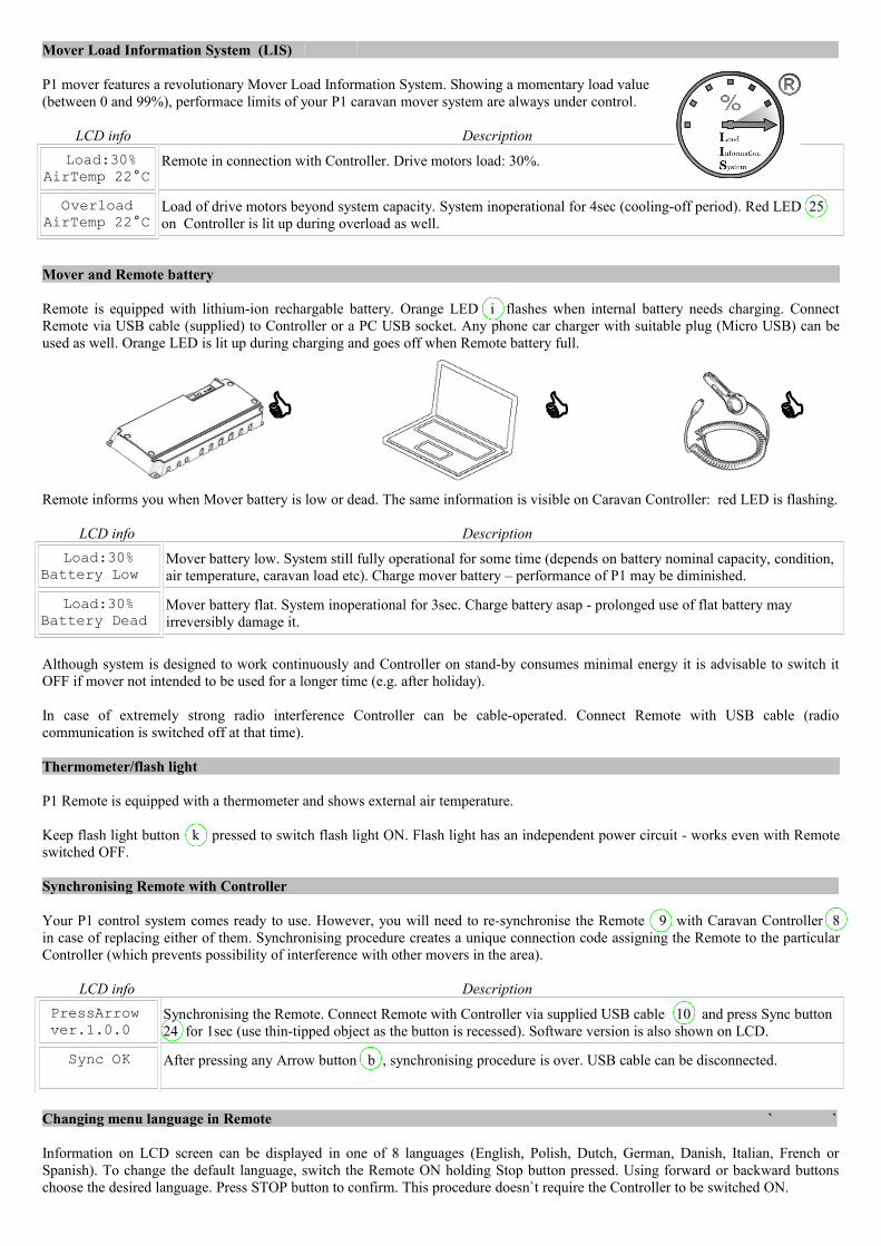
P1 mover features a revolutionary Mover Load Information System. Showing a momentary load value(between 0 and 99%), performace limits of your P1 caravan mover system are always under control.
LCD info Description Load:30%AirTemp 22°C
Remote in connection with Controller. Drive motors load: 30%.
OverloadAirTemp 22°C
Load of drive motors beyond system capacity. System inoperational for 4sec (cooling-off period). Red LED 25 on Controller is lit up during overload as well.
Mover and Remote battery
Remote is equipped with lithium-ion rechargable battery. Orange LED i flashes when internal battery needs charging. Connect Remote via USB cable (supplied) to Controller or a PC USB socket. Any phone car charger with suitable plug (Micro USB) can be used as well. Orange LED is lit up during charging and goes off when Remote battery full.
C C C
Remote informs you when Mover battery is low or dead. The same information is visible on Caravan Controller: red LED is flashing.
LCD info Description Load:30%Battery Low
Mover battery low. System still fully operational for some time (depends on battery nominal capacity, condition, air temperature, caravan load etc). Charge mover battery – performance of P1 may be diminished.
Load:30%Battery Dead
Mover battery flat. System inoperational for 3sec. Charge battery asap - prolonged use of flat battery may irreversibly damage it.
Although system is designed to work continuously and Controller on stand-by consumes minimal energy it is advisable to switch it OFF if mover not intended to be used for a longer time (e.g. after holiday).
In case of extremely strong radio interference Controller can be cable-operated. Connect Remote with USB cable (radio communication is switched off at that time).
Thermometer/flash light
P1 Remote is equipped with a thermometer and shows external air temperature.
Keep flash light button k pressed to switch flash light ON. Flash light has an independent power circuit - works even with Remote switched OFF.
Synchronising Remote with Controller
Your P1 control system comes ready to use. However, you will need to re-synchronise the Remote 9 with Caravan Controller 8 in case of replacing either of them. Synchronising procedure creates a unique connection code assigning the Remote to the particular Controller (which prevents possibility of interference with other movers in the area).
LCD info Description PressArrow ver.1.0.0
Synchronising the Remote. Connect Remote with Controller via supplied USB cable 10 and press Sync button 24 for 1sec (use thin-tipped object as the button is recessed). Software version is also shown on LCD.
Sync OK After pressing any Arrow button b , synchronising procedure is over. USB cable can be disconnected.
Changing menu language in Remote ` `
Information on LCD screen can be displayed in one of 8 languages (English, Polish, Dutch, German, Danish, Italian, French or Spanish). To change the default language, switch the Remote ON holding Stop button pressed. Using forward or backward buttons choose the desired language. Press STOP button to confirm. This procedure doesn`t require the Controller to be switched ON.
Guarantee Card
Thank you for the purchase of our P1 Mover. This is a high quality product for which we offer 5 years guarantee.
Model
Version
Drive Unit Serial No
Control Unit Serial No
Date of Purchase
Dealer Stamp
The manufacturer grants a guarantee for malfunctions in the product which are based on production and material faults.
A claim under guarantee shall not be observed:
– for parts subject to natural wear and tear,– as a result of using parts in the product that are not original P1 parts,– as a consequence of failure to obey the manufacturers instructions for installation and use,– as a consequence of improper handling.
Keep this card – you will be asked to present it in case of guarantee claim. Hope you will enjoy our mover for long years to come.
www.p1mover.com