carbide design in wear resistant powder materials
TRANSCRIPT

Presented at PM2008 World Congress in Washington, USA on June 11, 2008 1
CARBIDE DESIGN IN WEAR RESISTANT POWDER MATERIALS
Paul Nurthen (Höganäs Great Britain Ltd.)
Ola Bergman (Höganäs AB) Ingrid Hauer (Höganäs AB)
Abstract One area where powder metallurgy has proven to be superior to other means of manufacturing is wear resistant structures. Highly wear resistant high speed steel powders are commonly used in both HIPped and pressed and sintered forms. The carbide size and structure obtained depends both on production conditions and carbide type but the carbide types are fixed by the alloy composition. Alternative carbides have different properties and can be introduced in new alloy compositions. This paper presents the development of a new material where the carbides are designed to be of the most useful type for a sintered tool steel. A mix of small hard carbides and larger less hard carbides in a matrix capable of being hardened gives a good combination of properties. In some applications, the properties achieved are more effective than those obtained from the pressed and sintered M3/2 and M2 currently in use. Introduction High speed steel alloys are extremely wear resistant. In a sintered form containing pores, or in a composite form, high speed steel powders have also been proven to provide hard wearing components in arduous conditions and have played a valuable role in the production of components used in every day life for many years 1. However, high speed steel contains expensive elements whose price is volatile. This situation is likely to get worse and there is a need for alloys containing elements with lower and less volatile prices that can compete with high speed steel powder in PM applications. The wear resistant properties of high speed steel result from a combination of a hard matrix and a distribution of hard carbides generated through an appropriate starting chemistry and heat treatment programme 2. In order to provide new alloys that can meet the physical and economic requirements it is necessary to understand, and then control, the carbides and the matrix that are produced.

Presented at PM2008 World Congress in Washington, USA on June 11, 2008 2
The number of suitable carbide compositions for use in pre-alloyed heat treatable alloys is limited as they must be hard and thermally stable. Chemically, carbide compositions come in three general types: ionic (e.g. CaC2), covalent (e.g. SiC), and interstitial 3. The important carbides for prealloyed ferrous alloys are the interstitial types as these have high melting points and are very hard. They are also formed by elements that are suitable for pre-alloying in iron and exist in thermodynamic or kinetic equilibrium with ferrous based alloy matrices. Interstitial carbides are formed when carbon atoms are held in the interstices of a metallic atomic lattices and this restricts the elements available for suitable carbide formation mainly to transition metal groups 4b, 5b, and 6b (e.g. Ti, W, Mo, V). Chromium, in the first row of group 6b, and Mn, Fe, Co, and Ni from the first row of groups 7b and 8 do not strictly meet the interstitial carbide formation requirement but form carbides with distorted lattices and these carbides, at least for Fe and Cr, are of significance. A variety of carbide types are well recognised in tool steel type materials 4 and are based on vanadium, tungsten, molybdenum, and chromium. They are generally written in the form MxCy since M can be made up of a variety of elements although one or more may predominate. In addition, the x:y ratio may not be exact. Generally recognised carbide types are as follow:
M3C Orthorhombic, cementite type based on iron, manganese, and chromium M7C3 Hexagonal, chromium based M23C6 Face centred cubic, usually based on chromium M6C Face centred cubic, usually based on tungsten and molybdenum M2C Hexagonal, usually based on tungsten and molybdenum MC Face centred cubic, based on vanadium
An obvious parameter in considering the merits of the different carbide types is the hardness and Figure 1 shows a set of summarised data for the hardness of various carbide types and steel matrices measured by microhardness techniques. This data is not exact as the carbides themselves are not exact but the relative hardness of the different phases can be seen.
0
500
1000
1500
2000
2500
3000
MC - VC M2C -CrFe7C3
M6C -FeWMoC6
M23C6 Fe3C HSS Matrix Carbonsteel matrix
Hard phase
Vick
ers
Har
dnes
s, H
v 0.
02
0
500
1000
1500
2000
2500
Kno
op H
ardn
ess
Hv data HK data
Figure 1. Chart showing the relative microhardness of different carbide types and steel matrices found in tool steels. Knoop hardness adapted from Wilson 4 and Vickers hardness adapted from Thyssen 5.
Presented at PM2008 World Congress in Washington, USA on June 11, 2008 3
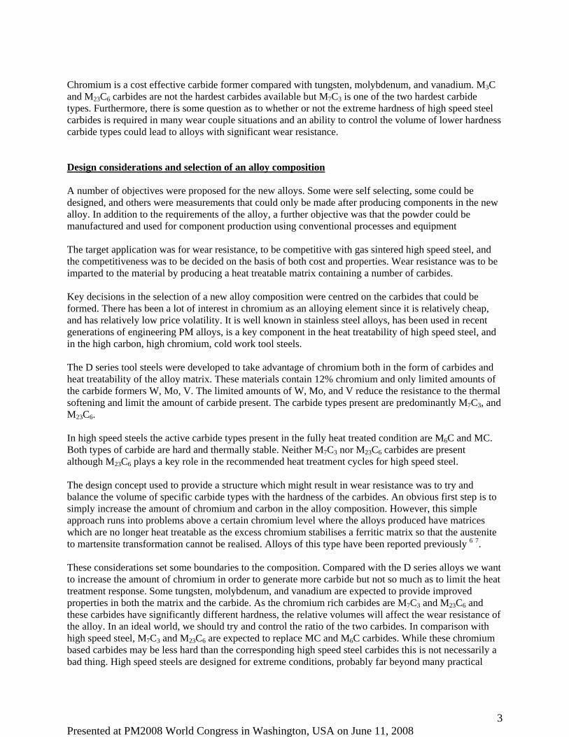
Chromium is a cost effective carbide former compared with tungsten, molybdenum, and vanadium. M3C and M23C6 carbides are not the hardest carbides available but M7C3 is one of the two hardest carbide types. Furthermore, there is some question as to whether or not the extreme hardness of high speed steel carbides is required in many wear couple situations and an ability to control the volume of lower hardness carbide types could lead to alloys with significant wear resistance. Design considerations and selection of an alloy composition A number of objectives were proposed for the new alloys. Some were self selecting, some could be designed, and others were measurements that could only be made after producing components in the new alloy. In addition to the requirements of the alloy, a further objective was that the powder could be manufactured and used for component production using conventional processes and equipment The target application was for wear resistance, to be competitive with gas sintered high speed steel, and the competitiveness was to be decided on the basis of both cost and properties. Wear resistance was to be imparted to the material by producing a heat treatable matrix containing a number of carbides. Key decisions in the selection of a new alloy composition were centred on the carbides that could be formed. There has been a lot of interest in chromium as an alloying element since it is relatively cheap, and has relatively low price volatility. It is well known in stainless steel alloys, has been used in recent generations of engineering PM alloys, is a key component in the heat treatability of high speed steel, and in the high carbon, high chromium, cold work tool steels. The D series tool steels were developed to take advantage of chromium both in the form of carbides and heat treatability of the alloy matrix. These materials contain 12% chromium and only limited amounts of the carbide formers W, Mo, V. The limited amounts of W, Mo, and V reduce the resistance to the thermal softening and limit the amount of carbide present. The carbide types present are predominantly M7C3, and M23C6. In high speed steels the active carbide types present in the fully heat treated condition are M6C and MC. Both types of carbide are hard and thermally stable. Neither M7C3 nor M23C6 carbides are present although M23C6 plays a key role in the recommended heat treatment cycles for high speed steel. The design concept used to provide a structure which might result in wear resistance was to try and balance the volume of specific carbide types with the hardness of the carbides. An obvious first step is to simply increase the amount of chromium and carbon in the alloy composition. However, this simple approach runs into problems above a certain chromium level where the alloys produced have matrices which are no longer heat treatable as the excess chromium stabilises a ferritic matrix so that the austenite to martensite transformation cannot be realised. Alloys of this type have been reported previously 6 7. These considerations set some boundaries to the composition. Compared with the D series alloys we want to increase the amount of chromium in order to generate more carbide but not so much as to limit the heat treatment response. Some tungsten, molybdenum, and vanadium are expected to provide improved properties in both the matrix and the carbide. As the chromium rich carbides are M7C3 and M23C6 and these carbides have significantly different hardness, the relative volumes will affect the wear resistance of the alloy. In an ideal world, we should try and control the ratio of the two carbides. In comparison with high speed steel, M7C3 and M23C6 are expected to replace MC and M6C carbides. While these chromium based carbides may be less hard than the corresponding high speed steel carbides this is not necessarily a bad thing. High speed steels are designed for extreme conditions, probably far beyond many practical

Presented at PM2008 World Congress in Washington, USA on June 11, 2008 4
wear conditions, and a reduction in the hardness and even the thermal stability of the carbides may not cause observable reductions in application properties. Wear resistance is a two sided thing and lower carbide hardness may actually result in improved wear couples both in face to face wear and in the abrasive debris that is formed. The arguments above are a little qualitative and it should be pointed out that firm analytical relationships between properties and carbide type and volume are not well established. As the potential for such alloy design is an ongoing and active strategy for Höganäs, this paper does not present a listing of the alloys being investigated. Rather it focuses on a specific alloy example, named OB1 that is now available commercially, and considers its manufacture, sintering and heat treatment, alloy characterisation with specific reference to the carbides present, and some basic properties. To provide reference points with known alloys, comparisons are made with D2, the commonest 12% die steel, and M2, the commonest high speed steel. Alloy Manufacture One of the compositions selected for further investigation was named OB1 and had the nominal composition shown in Table 1. This table also contains the mid point compositions for M2 and D2 available in ASTM standards.
Table 1. Nominal mid point compositions (wt%) of OB1 and reference materials D2, and M2
Alloy designation C Mn Si Cr V W Mo Fe
D2 8 1.50 0.35 0.35 12.00 0.80 0.95 Bal. M2 9 0.83 0.27 0.32 3.13 1.97 5.12 5.00 Bal. OB1 1.50 0.50 16.00 1.00 1.50 1.50 Bal.
The OB1 composition can be viewed in two ways either as a D2 material that has been modified by increasing the chromium, tungsten, and molybdenum or as high speed steel where the tungsten, molybdenum, and vanadium have been reduced and replaced by chromium. It will be shown later that the metallurgy of this material is closer to D2 than M2. All three of these compositions have high levels of hardenability and contain oxidisable elements. The established production method for high speed steel powder involves water atomising followed by vacuum annealing. This combination of processes is known to provide a powder material with minimum hardness (and thus potentially maximum compressibility) along with a low oxygen content maximising sinterability. This processing is well established in the production of high speed steel powders and subsequent sintering 10. Some experience in D2 production was available but further development was required to provide suitable powder production conditions for the higher chromium materials, D2 and OB1. Nevertheless, the production principles applied to high speed steel provided a good starting point and suitable production conditions were found. Since the powder is proposed as a standard press and sinter powder, a -100 mesh specification has been used (<2% > 160 micron) for the test powder.

Presented at PM2008 World Congress in Washington, USA on June 11, 2008 5
Alloy properties Interpretation of powder properties (apparent density and compressibility in particular) is often confused due to differing full density figures for different alloys. To avoid this confusion and ensure that proper comparisons were made, the novel alloy was HIPped and then annealed using a standard powder anneal cycle. The availability of the material in a solid form allows two development activities. Firstly an accurate full density figure can be obtained and secondly metallurgical characterisation of the alloy can be made in a fully dense form so that the effects of porosity, present in sintered parts, can be avoided. This means that macrohardness measurements become meaningful and surface preparation for metallographic examination becomes easier. To date, only annealed alloy data has been obtained from the HIPped material. Further characterisation in the thermally treated condition is envisaged using the fully dense material.
Table 2. Basic physical properties of OB1 and reference materials D2, and M2
Alloy designation
Full density, g/cc
Annealed Hardness, HB Notes
D2 7.7011 236 Usual range 217-25512, Mid point quoted M2 8.1611 227 Usual range 212-24113, Mid point quoted
OB1 7.75 255 Density using Archimedes’ principle on a solid HIPped sample. HB value converted from 268 Hv10
This table clearly shows the difference in the full densities between high speed steel and the high chromium materials that should be considered when reviewing apparent density and compressibility figures. Annealed hardness of the OB1 has been measured directly using Hv10 but to make an annealed hardness comparison this has been converted to HB using tabulated conversions for comparison with the mid point of the usual anneal hardness taken from the literature. The hardness ranking has M2 as the softest material and OB1 as harder than D2. There are two features of the alloys that may contribute to this. Both D2 and OB1 have high levels of carbon, compared with M2, that will precipitate in the form of carbide (since carbon cannot stay in solution in ferrite). This may lead to higher volumes of carbide and, despite the fact that M2 contains some MC type carbide and only a limited amount of M23C6, high volumes of chromium based carbides might be expected to have an adverse effect on the annealed hardness. A further issue is the level of chromium in the alloys. In the case of M2 most of the chromium is precipitated in the form of carbide. However, in the case of OB1 and D2 there is an excess of chromium, some of which will be in solution in the matrix, and this will lead to higher matrix hardness. This difference in the annealed hardness can be expected to be reflected in powder properties, compressibility in particular. Some basic powder properties are shown in Table 3.
Table 3. Basic powder properties of OB1 and reference materials D2, and M2
Alloy Apparent density, g/cc (% of FTD)
Compressibility, g/cc (% of FTD) Green Strength, MPa
D2 2.50 (32.5%) 6.42 (83.3%) 17.09 M2 2.35 (28.8%) 6.63 (81.3%) 19.85 OB1 2.45 (31.6%) 6.18 (79.7%) 12.92

Presented at PM2008 World Congress in Washington, USA on June 11, 2008 6
The compressibility and green strength was measured on samples pressed at a compaction pressure of 700 MPa. In both cases the powder was lubricated by blending with 1wt% Acrawax. When viewed as a percentage of full density the compressibility does not follow the annealed hardness described above. OB1 does result in the lowest pressed fractional density but D2 achieves a higher fractional density than M2. However, it can also be seen that the M2 starts from a lower density than both the OB1 and D2. If we look at the difference in fractional density between the apparent density and the green density we can see that the difference now ranks in the same order as the hardness with M2 undergoing the greatest change. Green strength follows this same ranking reflecting the common observation that lower apparent densities result in higher green strengths. The most important conclusion is that although both the compressibility and green strength of the OB1 are lower than that for both D2 and M2 the values are such that the material can be used in a standard press and sinter technologies Alloy and powder characterisation The annealed structure should be the simplest, it is a thermodynamically equilibrated structure in which the carbon has been rejected from the ferrite matrix and precipitated as alloy carbides. Due to the amount of chromium and other strong carbide forming elements the volume of carbide formed is high. The microstructure is shown in Figure 2.
Figure 2. Micrographs showing the annealed structure of HIPped OB1. a) Light microscope, Etched 3.3 reagent to reveal the carbide structure b) SEM picture of sample etched in Murakami’s reagent to reveal selected carbide detail. Attempting to identify carbides is an art. Possible methods include differential etching, SEM element mapping, SEM spot analysis, X-ray diffraction and others. Despite having a range of analytical tools we cannot, at this time, be completely sure of the specific carbide types present. As will be seen in the balance of the paper, there is a weight of evidence but there is also contradictory evidence that we cannot
Pale carbide attacked by etch
Rounded carbide showing surface markings Small black circular feature
Dark grey carbide

Presented at PM2008 World Congress in Washington, USA on June 11, 2008 7
currently explain. A particular problem is the scale of the microstructure. With carbide sizes of a few microns the equipment we have been able to use has been unable to provide accurate analysis of individual carbides. However, given that we have chromium based carbides we expect to have M7C3 and M23C6. The optical micrograph is a sample etched in 3.3 reagent. This reagent outlines carbides and, in common steels, also highlights grain boundaries. A large volume of carbide of varying size and morphology can be seen. The grain boundaries are not easily seen and this may be a result of the high chromium content imparting a degree of corrosion resistance to the matrix. Etching with Murakami’s reagent, a selective carbide etch, reveals fewer carbides in the light microscope indicating that a variety of carbide types are present.
Figure 3. Element mapping diagrams derived from the annealed OB1 sample area shown in Figure 2. Viewing the Murakami’s etched sample in the SEM shows some additional features. Large blocky pale carbides affected by the etch are clearly visible. Smaller, pale rounded carbides are also revealed and often have peculiar regular markings. These look as if they could be cracks but SEM observations on unetched samples indicates that these are etching features. It is believed that these two carbides are the same type, perhaps formed at different stages of processing, producing different morphologies. A third rounded carbide type shows as dark against the matrix with relatively low contrast and no outline etching. There is also the possibility of an additional phase which shows up as black, almost perfectly circular, and about half a micron or less. Evidence from other related compositions suggests that this is a real phase and not porosity. Even the large carbides are too small for accurate compositional analysis of individual carbides with the equipment available. However, spot analysis allowed approximate iron chromium ratios to be determined. The large pale carbides had an Fe:Cr ratio of 55:35 whereas the dark grey carbide had more chromium with a ratio of around 35:55. Both showed concentrations of the other elements (W, Mo, V) with

Presented at PM2008 World Congress in Washington, USA on June 11, 2008 8
vanadium most concentrated in the dark grey particles and the tungsten and molybdenum slightly more concentrated in the pale carbide compared with the dark grey particles. These observations are confirmed by the element mapping. Chromium is concentrated in both the main carbide types and with care it can be seen that the dark grey particles have a higher chromium concentration. No conclusions could be drawn about the other elements or about the small black circular features observed. If we assume two major carbide types (M7C3 and M23C6) the evidence for carbide identification is contradictory. The standard etching response to Murakami’s reagent is that M7C3 is attacked and M23C6 is only faintly attacked. This suggests that the pale carbide is M7C3, and this is consistent with previously reported work on the 23% chromium alloy HCx 7. However, it is shown below that the pale carbide mostly disappears during sintering leaving the poorly etched dark carbide. Of the two carbides M7C3 is expected to be favoured at high temperatures and is the more thermally stable of the two carbides so this behaviour is not what would be expected based on the etching response of the material. The carbide composition evidence from the SEM is also consistent with expectations if the pale carbide is M7C3 and not M23C6 as suggested by the etching. Additional work is required to be make a completely positive identification of the carbides but it is clearly shown that the annealed structure consists of two dominant carbides along with a possible third carbide. Component production There is a scientific interest in the microstructure of the annealed material but the powder is not really of use unless it can be sintered to useful components. The predicted metallurgy of the alloy and the comparison with high speed steel materials suggested a suitable consolidation and heat treatment route as outlined below. However, there is clearly the possibility of optimisation in the future. Parts were compacted at 700MPa after lubrication with 1 wt% Acrawax the density of parts being described in Table 4. Dewaxing was carried out as part of the sintering cycle. Sintering conditions were selected based on experience of sintering high speed steels and D2 and after selecting the cycle, preliminary experiments were used to confirm its suitability before proceeding with the comparative trials. The conditions used in a laboratory sintering furnace were 1120ºC for 20 minutes at temperature in a 90:10 nitrogen:hydrogen atmospherere with a 0.2% carbon potential controlled by a methane addition. To provide cost effective processing it is important that the material can be hardened as part of the cooling process from sintering. With these materials, the cooling rate from sintering is not usually a problem and preliminary experiments showed that the natural cooling rate available in the development sintering furnace (approximately 1ºC/sec) was sufficient to create a hardened structure. A more usual problem for such highly alloyed materials is the possibility that the martensite transformation finish temperature is below room temperature and this leads to retained austenite. If not avoided or removed by thermal processing this can lead to a number of unwanted characteristics. A convenient way to complete the martensite transformation is by cryogenically cooling the sintered parts using liquid nitrogen. This should be done soon after the parts reach room temperature to avoid the phenomenon of austenite stabilisation. Preliminary trials with OB1 showed that the effect of cryogenic

Presented at PM2008 World Congress in Washington, USA on June 11, 2008 9
cooling was to increase the hardness of the material compared with the material before cryogenic cooling. This is as expected and is explained by the conversion of any remnant austenite to martensite. The structure obtained in M2 and D2 and expected in OB1 after cooling is untempered martensite and a selection of carbides. This structure usually has relatively low toughness, is thermally unstable, and requires tempering in order to stabilise the structure and optimise the properties. The exact temperature required for tempering depends in particular on the austenitising temperature (which controls the amount and type of carbide that dissolves in the matrix) and the properties that are required. High speed steels typically require tempering at around 550ºC to achieve peak hardness. Detailed measurement of the heat treatment response of OB1 has not yet been carried out but preliminary experiments showed that a temper of 1 hour at 550ºC provided reasonable properties in all of the materials used in the study. It should be noted that the sintering temperature (corresponding to the austenitising temperature) is low for high speed steels, and high for D2. The tempering temperature is correct for M2 (had it been austenitised at higher temperatures) but is high for D2 14. So the thermal treatment parameters are a compromise for the known alloys. Nevertheless, the main objective of this programme is to investigate the carbides and interactions occurring during processing and the use of a common processing route allows direct comparisons to be made. Mechanical and physical properties A number of measurements were made during and after the production of the samples as described above. Density was measured on the green parts, and the finished parts (that is after sintering, cry cooling and tempering). Dimensional change referenced to the green compact was determined in the finished condition but also after cry cooling and warming to room temperature. Room temperature hardness along with room temperature compressive yield strength was measured on all three materials. A summary of this data is shown in Table 4
Table 4. Component data obtained during and after processing
Alloy FTD, g/cc
GD, g/cc (%FTD)
Dimensional change, % (green to
cryo-cooled)
Dimensional change, % (green to
tempered)
Tempered density,
g/cc (%FTD)
Hv10 Compressive 0.2% proof stress, MPa
D2 7.70 6.42 (83.3) 0.16 -0.01 6.41
(83.2) 321 1373
M2 8.16 6.63 (81.3) 0.16 -0.02 6.64
(81.3) 322 1366
OB1 7.75 6.18 (79.7) 0.39 0.30 6.12
(79.0) 333 1288
The data shown does not appear to be completely self consistent since, for D2, a linear shrinkage (green to tempered) appears to result in a dilation based on the density. However, this is most likely caused by the measurement accuracy. A number of results stand out:

Presented at PM2008 World Congress in Washington, USA on June 11, 2008 10
• D2 and M2 show very similar results both in size change and hardness. D2 has a usual working hardness only slightly lower than M2 but, in the sintered condition, has a slightly lower porosity. This combination of factors appears to lead to a very similar hardness.
• All parts show a degree of expansion during the sintering process. This will be a combination of the sintering process and the change in structure from a ferrite matrix with carbides to martensite with carbides. However, the relative contribution of these factors is not known.
• All materials show a contraction during the tempering process which is to be expected as the martensite tempers.
• Compared with M2 and D2, OB1 shows markedly different size change results. The expansion during the sintering and cryo-cooling stages is greater than either of the standard alloys. Furthermore, the contraction occurring during the tempering stage is less than that obtained with the reference alloys. As a result, the OB1 material contains noticeably more porosity than the reference alloys. Again the reasons for this behaviour are not known and more detailed structural and materials analysis will be required in order to understand this
• Despite the higher porosity, the macrohardness of the OB1 alloy exceeds that of both the M2 and the D2 material produced under the same conditions.
• The compressive yields strength of the OB1 is slightly lower than both M2 and D2. Metallography and carbides Comparative micrographs of D2, M2, and OB1 in the sintered and cryo-cooled condition and the tempered condition are shown in Figure 4 to Figure 6. The samples are etched in Murakami’s reagent. The cooling rate from sintering is fast enough to harden the alloys and the carbide structure found in the sintered and cryo-cooled condition reflects the carbide structure at the end of sintering. Some carbide precipitation may occur during cooling but the structures are no longer at thermodynamic equilibrium. The structure observed in the tempered condition is also non-equilibrium and any differences observed between the cooled and tempered microstructures should reflect the tempering processes.
Figure 4. Micrographs of M2, etched in Murakami’s reagent, comparing the sintered and cryo-cooled condition with the tempered condition The easiest structures to interpret are those seen in the M2. The M2 tempered condition is known to consist predominantly of M6C carbide, a tungsten molybdenum rich carbide. There should be no M23C6 present since in high speed steels this should all dissolve at a temperature of around 1100ºC. A certain amount of MC carbide should be present but this is difficult to see as it will be relatively fine, little

Presented at PM2008 World Congress in Washington, USA on June 11, 2008 11
dissolves at the temperatures used and most of what does should be precipitated as very fine carbide within the martensite. The observed microstructures are consistent with expectations. Murakami’s reagent is reported to affect M6C carbide by outlining in black and colouring brown and this corresponds well with the observed features and we can interpret this as being a large volume of the expected M6C carbide. The matrix remains unattacked but we can assume the matrix to be martensite, tempered, or untempered depending on the heat treatment condition. There is little change in the observed microstructure through tempering and this is again what might be expected as conventional HSS tempering stress relieves the martensite and precipitates mainly sub optical carbides within the martensite. These effects are not processes that we can expect to observe optically.
Figure 5. Micrographs of D2, etched in Murakami’s reagent, comparing the sintered and cryo-cooled condition with the tempered condition D2 shows a distinctly different microstructure. Untempered and tempered martensite can again be expected for the matrix. Dispersed within it, a large number of carbides can be observed but, in the cryo- cooled condition, none of these are coloured or outlined. Etching with 3.3 reveals a similar carbide volume and observation in the SEM showed only dark unattacked carbides. Once tempered, the carbides remain similar both in size and distribution but the carbides are better outlined. It is possible that the visual change is a result of the etching practice. However, during the tempering process we might expect an increase in the chemical partition between the carbide and the matrix and this may lead to a more defined resolution. We can conclude that the D2 structure contains, predominantly, a single carbide type The etching response seen here continues to contradict the expected carbide identification. The carbide type expected in D2 is M7C3. The carbide observed in the D2 has clearly not been attacked by the etch and resemble the darker carbides in a number of ways. We should conclude that the unattacked dark carbide in this case is M7C3 and it would be surprising if this identification were not the same in the annealed condition. However this continues to contradict the accepted response to Murakami’s etch. The importance of the correct carbide identification is that the hardness of the two carbides is very different and, in order to control the wear resistance of new alloys by controlling the carbides generated, it is important to correctly identify the carbide types.

Presented at PM2008 World Congress in Washington, USA on June 11, 2008 12
Figure 6. Micrographs of OB1, etched in Murakami’s reagent, comparing the sintered and cryo-cooled condition with the tempered condition The new alloy OB1 has an etching response that shows some similarity to D2 in the cryo-cooled condition. Two carbide types can be seen, a predominant, faintly attacked carbide which appears similar to that observed in D2 but present in greater volume, and a small volume of outlined, rounded carbides which are coloured brown. It seems reasonable to assume that the faintly attacked carbide is of a similar type to that found in D2. The brown carbides show some similarity to the M6C found in M2 and the Murakamis response also suggests M6C carbide but this is very unlikely to be a correct identification. Comparing the sintered and annealed structures it is an immediate reaction to assume that the brown outlined carbide in the sintered structure is the remnant of the pale attacked carbide and the faintly attacked carbide is the unattacked dark carbide observed in the SEM. A simple explanation is that the one carbide dissolves at the sintering temperature while the other remains stable. Since the quantity of pale, attacked carbide is very much reduced, the most likely identification is that this is an M23C6 type carbide. We can assume that some carbides dissolve during the sintering process, this is necessary to allow a proper heat treatment response. However, we have also observed that the volume of the faintly attacked phase in the sintered condition is greater than that present in the annealed sample. In order to explain this we can propose that one carbide (the pale, attacked carbide) transforms into the faintly attacked carbide during the sintering process. This should not, perhaps, be a surprise we are simply proposing that, at the sintering temperature, the material moves into a phase field where the carbide types or ratios is different to that in the annealed condition. If we try and identify what is happening we would propose that the M23C6 dissolves and re-precipitates or transforms in situ into M7C3 since this is the more stable carbide at high temperatures. Such an argument would be consistent with existing knowledge but still suffers from the reversal of carbide types identified by the etch response in the annealed material. Tempering shows further interesting features. The dark brown rounded carbide remains but, unlike D2, the majority of the previously un-outlined carbide now becomes outlined and coloured. Although this carbide appears to be different to those previously identified, it is believed, based on the similar size distribution and shape, that it is still closely related to the original carbide and is the M7C3 type which promotes high hardness and thermal softening resistance. The change in appearance can be put down to chemical partitioning during tempering, a more extreme example than that seen in the D2. What we can conclude is that there is a significant response to the tempering process.

Presented at PM2008 World Congress in Washington, USA on June 11, 2008 13
Figure 7. Micrograph showing the sintered structure of OB1. Photograph taken using and SEM of a sample etched in Murakami’s reagent to attack selected carbides.
Figure 8. Element mapping diagrams derived from the tempered OB1 sample, etched in Murakami’s reagent to reveal carbides Observation of these OB1 samples in the SEM reveals additional information.
• There is no obvious difference between the dark carbide in the sintered and in the tempered condition. This provides additional evidence that they are closely related. These carbides are also very similar in appearance to the dark carbides present in the annealed material.
• In the sintered condition in particular, but also observed in the tempered condition, there are a number of very fine small circular black carbides which can be assumed to be those previously seen in the annealed condition and these remain unidentified.
• In both cases, we see carbides (appearing pale in the SEM) which we assume to be the brown coloured carbide seen in the optical microscope. These seem more obvious in the heat treated
Presented at PM2008 World Congress in Washington, USA on June 11, 2008 14
condition and also show the surface patterns previously observed. This suggests that these carbides are the remnants of the white carbides seen in the annealed structure. However, there is a key difference and this is seen in the element mapping. The enhanced chromium content of the dark carbides is clearly seen. However, it is impossible to detect the location of the remnant white carbides from any mapped element. This is possibly due to a redistribution of elements during the sintering stage resulting in a low chromium content carbide.
If these explanations are correct, OB1 has been shown to be a material that undergoes significant phase and phase volume changes during the sintering step and further phase compositional changes during tempering. Both of these processes will be temperature and possibly time dependant and presents possibilities for process optimisation to maximise specific properties or process parameter selection to provide a range of properties from a single alloy. Summary and Conclusions This paper has introduced a new alloy produced as a water atomised and vacuum annealed powder. The metallography and some basic physical properties of the sintered alloy have been compared with sintered tool and high speed steel material. The concept for the new alloy was to produce a press and sinter material that could compete with high speed steel powders in a cost effective manner by reducing the requirement for the more expensive carbide forming elements. The approach taken in developing this alloy was to consider the type and volume of carbides formed and to compare these with D series and high speed steel alloys. A further requirement was that the new alloy powder could be manufactured and processed using existing conventional processes. The investigation of the new alloy reported in this paper is a work in progress. Nevertheless, the results clearly show that modified specification powders, outside normal standard compositions, can be manufactured in powder form and subsequently processed into components by readily available processes and this opens up possibilities for “designer” alloys. Carbide types and volumes have been shown to be modified compared with conventional specified alloys, although a complete analytical description of these carbides has not been possible. In particular, the etching response of the carbides to Murakami’s etch does not seem to match other identification data. The basic properties of the new material have been show to have sufficient promise to continue the development. Future work will be focussed on optimising the processing conditions to maximise specific properties, or to provide selectable property values, and on testing the material in real world applications. There is also scope for further alloy development based on an understanding of the metallurgical reactions involving the carbides and martensitic matrix, an approach that Höganäs will continue to pursue as applications continue to demand cost effective solutions for specific applications. References 1. M S Lane and P Smith, “Developments in sintered valve seat inserts”, Metal Powder Report,
September 1982, pp 474-480.

Presented at PM2008 World Congress in Washington, USA on June 11, 2008 15
2 G Roberts, G Krauss, and R Kennedy, Tool Steels, 5th Edition, Chapter 4, 1997, publ. ASM
International, Materials Park, Ohio
3. F Cotton and G Wilkinson, Advanced inorganic chemistry, 3rd Edition, pp290-293, 1972, publ. J Wiley
4. R Wilson, Metallurgy and heat treatment of tool steels, p69, 1975, publ. McGraw-Hill, London
5. H Brandis, E Haberling, and H Weigand, Metallurgical aspects of carbides in high speed steels, Thyssen Edelstahl, Technische Berichte, Special Issue 1983.
6. J Saunders, P Nurthen, N Trilk, P Woods, A new P/M stainless steel with improved corrosion and wear resistance, Advances in Powder Metallurgy & Particulate Materials - 1995, Volume 3, Part 11, pp 31-43, Proceedings of the 1995 World Congress on Powder Metallurgy and Particulate Materials, Seattle
7. J Saunders, P Nurthen, N Trilk, The mechanical, corrosion and wear properties of a novel stainless steel composition, Advances in Powder Metallurgy & Particulate Materials - 1996, Volume 5, Part 17, pp 113-126, Proceedings of the 1996 World Congress on Powder Metallurgy and Particulate Materials, Washington
8. Standard specification for tool steels alloy, Designation A681-07, ASTM International, PA
9. Standard specification for tool steel high speed, Designation A600-92a, ASTM International, PA
10. M Igharo and J Wood, Sintered high speed steel alloy powders for wear applications, Powder Metallurgy, 1990, Vol. 33, No. 4, pp313-320
11. Properties and selection: Irons, steels, and high-performance alloys, Metals Handbook, Volume 1, 10th Edition, p774, publ. ASM International, Materials Park, Ohio
12. G Roberts, G Krauss, and R Kennedy, Tool Steels, 5th Edition, p204, 1997, publ. ASM International, Materials Park, Ohio
13. Ibid. p255
14. R Wilson, Metallurgy and heat treatment of tool steels, p141 and p181, 1975, publ. McGraw-Hill, London