carbon fiber tank, regulator & fill station with...
TRANSCRIPT

336U BLK
Carbon fiber tank,regulator & fill station with hose
Fill pressure: 4,500 psi (310 bar)Output: 2,900 psi (200 bar)
Patent numbers:6,851,447 • 7,059,343 • 7,051,751

Contents
2
Illustrations and photographs are for demonstration purposes only and may not show the exact item purchased.
Dealers: This owner’s manual must be given to the retail customer with the tank at the time of purchase. Shooters are advised to keep this manual and associated instructions for future reference by all users of this high-pressure air tank even if it’s resold or loaned.
Safety system ......................................................................... 3
Fill your tank.......................................................................... 4
Connecting ..............................................................................5
Gas types .................................................................................5
Service & rebuild your regulator ........................................... 6
Low-pressure burst disk replacement ....................................7
Fill check-valve ...................................................................... 8
Fill station ..........................................................................9-11
Additional warnings .............................................................12
General maintenance............................................................13
Troubleshooting ...................................................................13
Warranty ...............................................................................14
Parts list ................................................................................15
Composite cylinders must behydrostatically tested every 5 years.
Plus, composite cylinders have amaximum life of 15 years
from their originalhydrostatic test date.
ALWAYS make sure your cylinder iswithin its retest period.
3
Safety system
Your Air Venturi regulator is equipped with an ASTM-compliant high-pressure bottle burst disc re-quired by the Department of Transpor-tation (DOT).
The regulator also has a low-pressure safety burst disk (stamped 5K).
The 5K psi safety burst disk protects you and your gun in the unlikely event the regulator fails.
If the 5K psi safety burst disk vents, it did so for a reason. We recommend you do the following:
1. Disassemble the regulator (see Service and rebuild procedures, page 5).
2. Inspect the regulator for contamina-tion and clean it if necessary.
3. Install a new 5K psi burst disc (in-structions on page 6).
4. If the 5K psi burst disk vents after rebuild, contact Air Venturi at 216-220-1180.
Your Air Venturi regulator has a safety vent groove and safety snubber
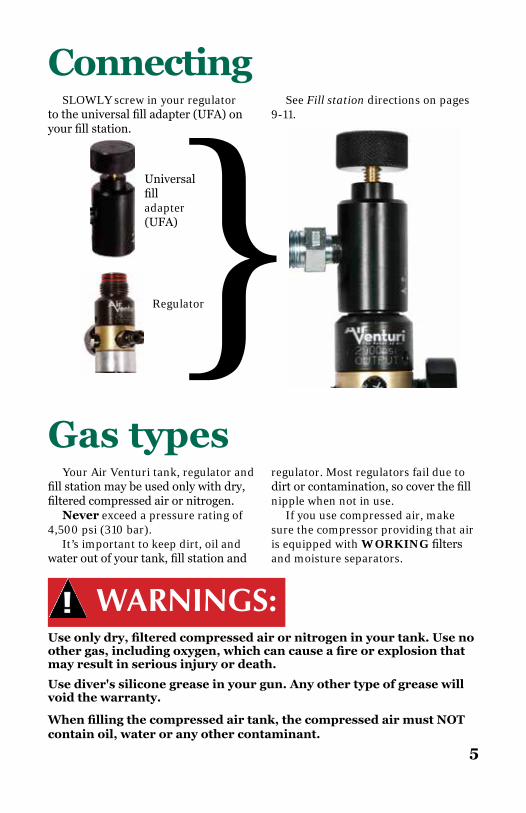
Always make sure there’s no gap between the bottle and the regulator seal. If there IS a gap:
1. STOP! 2. DoNOTfillyoursystem.3. Do NOT use your system.4. Place system on ground and wait
for it to fully degas.
5. Immedi-ately contact aqualifiedairsmith or Air Venturi tech support (216-220-1180).
Make sure there’sno gap here
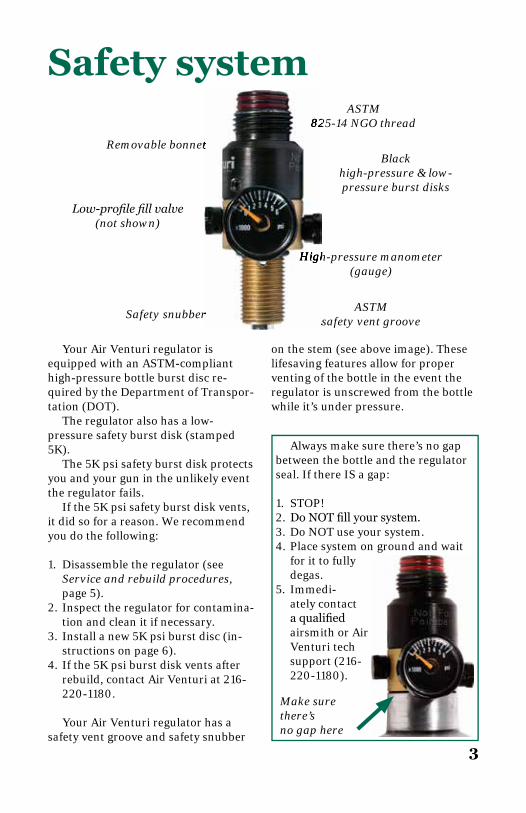
ASTM825-14 NGO thread
Blackhigh-pressure & low-pressure burst disks
High-pressure manometer (gauge)
ASTMsafety vent groove
Low-profi le fi ll valve(not shown)
Removable bonnet
on the stem (see above image). These lifesaving features allow for proper venting of the bottle in the event the regulator is unscrewed from the bottle while it’s under pressure.
Safety snubber
825-14 NGO thread
High-pressure manometer
safety vent groove
Removable bonnet
Safety snubber

4
Fill your tankTofillyourcarbonfibertank,connectthetank'sfillporttothefillsource.Do
NOT fi ll the tank using the fi ll station!
Fill your carbon fi ber tank using the tank's
fi ll port
Do NOT useuniversal fi ll adapter
to fi ll tank!It will damage
the regulator &VOID your warranty!The fi ll station is used only to fi ll
your gun's reservoir!
5
Your Air Venturi tank, regulator and fillstationmaybeusedonlywithdry,filteredcompressedairornitrogen.
Never exceed a pressure rating of 4,500 psi (310 bar).
It’s important to keep dirt, oil and wateroutofyourtank,fillstationand
WARNINGS:Use only dry, fi ltered compressed air or nitrogen in your tank. Use no other gas, including oxygen, which can cause a fi re or explosion that may result in serious injury or death.
When fi lling the compressed air tank, the compressed air must NOT contain oil, water or any other contaminant.
Use diver's silicone grease in your gun. Any other type of grease will void the warranty.
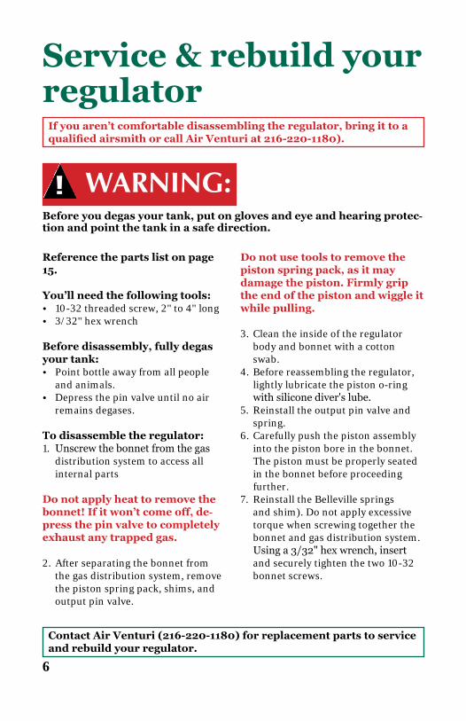
ConnectingSLOWLY screw in your regulator
totheuniversalfilladapter(UFA)onyourfillstation.
See Fill station directions on pages 9-11.
Universalfilladapter (UFA)
Regulator
regulator. Most regulators fail due to dirtorcontamination,socoverthefillnipple when not in use.
If you use compressed air, make sure the compressor providing that air is equipped with WORKING filtersand moisture separators.
}Gas types
6
Service & rebuild your regulator
Reference the parts list on page 15.
You’ll need the following tools:• 10-32 threaded screw, 2" to 4" long• 3/32" hex wrench
Before disassembly, fully degas your tank:• Point bottle away from all people
and animals.• Depress the pin valve until no air
remains degases.
To disassemble the regulator:1. Unscrewthebonnetfromthegas
distribution system to access all internal parts
Do not apply heat to remove the bonnet! If it won’t come off, de-press the pin valve to completely exhaust any trapped gas.
2. After separating the bonnet from the gas distribution system, remove the piston spring pack, shims, and output pin valve.
WARNING:Before you degas your tank, put on gloves and eye and hearing protec-tion and point the tank in a safe direction.
Contact Air Venturi (216-220-1180) for replacement parts to service and rebuild your regulator.
If you aren’t comfortable disassembling the regulator, bring it to a qualified airsmith or call Air Venturi at 216-220-1180).
Do not use tools to remove the piston spring pack, as it may damage the piston. Firmly grip the end of the piston and wiggle it while pulling.
3. Clean the inside of the regulator body and bonnet with a cotton swab.
4. Before reassembling the regulator, lightly lubricate the piston o-ring withsiliconediver'slube.
5. Reinstall the output pin valve and spring.
6. Carefully push the piston assembly into the piston bore in the bonnet. The piston must be properly seated in the bonnet before proceeding further.
7. Reinstall the Belleville springs and shim). Do not apply excessive torque when screwing together the bonnet and gas distribution system. Usinga3/32"hexwrench,insertand securely tighten the two 10-32 bonnet screws.

Low-pressure burst disk replacement
You’ll need the following tools:• 3/8" box wrench• 3/8-24-UNF-2Bgo/no-gogauge• Inch-pound torque wrench
AnASTM-compliantunifiedburstdisk is used on your Air Venturi regula-tor. Burst disks are required by the U.S.Dept.ofTransportation(DOT)and Transport Canada (TC).
For your 4500 psi Air Venturi carbonfibertank,there’sa7500psihigh-pressure burst disk rated for N2/HPA storage bottles.
How to replace your unifi ed burst disk assembly:1. Unscrew(turncounterclockwise)
the failed unit and discard it. These are not serviceable and have no further use.
2. Visually inspect the female port for damageordebris.Ifyoufinddebris,blow it out. If the port is dam-aged, do NOT replace the disk.
WARNING:Serious personal injury or death may result from improper disk replacement. It's essential that you replace failed disks with exact replacements. ASTM unifi ed burst disks have the pressure identifi cation stamped on the head of the unifi ed disks. Some may have the pressure identifi er on the side of the unifi ed disk. The correct low-pressure burst disk for your Air Venturi 4500 psi tank is rated 5000 psi. Do not replace it with a disk with any other rating!
7
Contact Air Venturi at 216-220-1180 for OEM replacement parts to service and rebuild your regulator.
If you aren’t comfortable replacing the burst disk, bring it to a qualifi ed airsmith or call Air Venturi at 216-220-1180.
Call Air Venturi (216-220-1180) for assistance or contact a qualifi ed airsmith. We recom-mend that the female port be checked with a 3/8-24-UNF-2B go/no-go gauge (available at in-dustrial supply stores or www.mscdirect.com).
3. Screw in the new replacement unit.Usinganinch-poundtorquewrench, torque it to a minimum of 55 inch-pounds and maximum of 95 inch-pounds.
4. If the burst disk assembly does not seal at 95 inch-pounds, call Air Venturi at 216-220-1180 or have it inspectedbyaqualifiedairsmith.
Fill check-valveIf you aren’t comfortable replacing the fi ll check-valve, bring it to a qualifi ed airsmith or call Air Venturi at 216-220-1180.
8
Contact Air Venturi at 216-220-1180 for OEM replacement parts to service and and replace your fi ll check-valve.
Your fi ll check-valve requires periodic inspection. If it’s leak-ing or you notice damage on the exterior, replace it.
Refer to the parts list on page 15.
You’ll need the following tool to replace your fi ll check-valve:• 7/16" wrench• 1/8-27-NPT go/no-go gauge
1. Completely degas your tank by depressing the pin valve.
2. Usinga7/16"wrench,removetheoldfillcheck-valveassembly.
3. Remove any old sealant and debris from the port.
4. Inspectthe1/8"NPTfemalefillcheck-valve port threads on the gas distributionbody.Useyourgo/no-go gauge (available at indus-
Before you degas your tank, put on gloves and eye and hearing protec-tion and point the tank in a safe direction.
WARNING:Never inject oil into the regulator through the full check-valve or allow oil to enter the bottle. Oil droplets ignite during the fi ll process and can lead to injury or death.
trial supply stores or www.msc-direct.com) to check the threads. If threads are damaged or worn, STOP! Do NOT use your regulator. Contact a qualifi ed airsmith or call Air Venturi at 216-220-1180.
5. A thread sealant has already been applied to the threads on your OEM fillcheck-valve.Donotuseanyad-ditional sealant or PTFE tape.
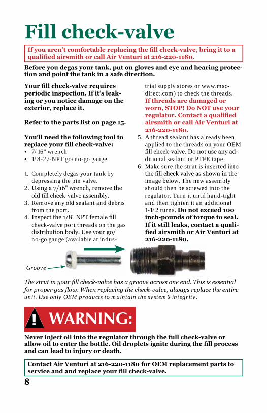
6. Make sure the strut is inserted into thefillcheckvalveasshownintheimage below. The new assembly should then be screwed into the regulator. Turn it until hand-tight and then tighten it an additional 1-1/2 turns. Do not exceed 100 inch-pounds of torque to seal. If it still leaks, contact a quali-fi ed airsmith or Air Venturi at 216-220-1180.
The strut in your fi ll check-valve has a groove across one end. This is essential for proper gas fl ow. When replacing the check-valve, always replace the entire unit. Use only OEM products to maintain the system’s integrity.
Groove

Fill station
Do not use petroleum or petroleum-based products in or on the fi ll station or a precharged pneumatic airgun (PCP). Petroleum may cause fi re or explosion and result in injury or death.
Refer to fi g. 1, above.
Yourfillstationhasauniversalfilladapter(UFA)ontheinputsideand
9
WARNINGS:On the back of the fi ll station is a vent hole. For safety reasons, the vent hole (part 7, fi g. 1) must be directed AWAY from the operator and bystanders.
The hose, fi ttings and muffl ers must have a minimum working pres-sure of 3000 psi. Do not use a sintered bronze muffl er, which is rated to only 125 psi!
Never operate the PCP fi ll station unless a PCP air gun is attached to the fi ll adapter at the end of the fi ll hose. Operating the fi ll station without a PCP airgun attached to the fi ll adapter will cause the hose to whip and may cause injury.
Compressed air rushes out of the vent hole (part 7, fi g. 1) when reliev-eing pressure from the fi ll hose. Use caution in directing the venting air.
Do NOT disconnect the hose under pressure, as it may damage the hose fi tting and result in injury to the operator.
connects to your Air Venture high-pressure regulator.
The vent hole has 1/8" NPT threads and can be attached to a vent hose or muffler,ifyouwouldliketoreducethesound that accompanies venting the airinthelineafteryou'redonefillingthe gun.
Do NOT over-tighten the vent knob (part 5, fi g. 1), as this may damage the seal. Turn the knob enough to stop the release of gas.
Before using your fi ll station, put on gloves and eye and hearing pro-tection.
Fig. 1
1.Universalfilladapter(UFA)2.UFAknob3. Hose4. Vent station
5. Vent knob6. Quick-disconnect7. Vent hole
Fig. 1
4. Vent station1
2
3
4
5
6
7

Fill station continuedBefore using your fi ll station, put on gloves and eye and hearing pro-tection.
10
Refer to fi g. 1 on page 9.
1. Closetheventstation(part4,fig.1)by fully turning the vent knob (part 5,fig.1)inaclockwisedirection.Do NOT over-tighten!
2. TurntheUFAknob(part2,fig.1) counterclockwise until it stops. ScrewtheUFA(part1,fig.1)ontoyour high-pressure air bottle regu-lator. Be sure all components are clean and dry! Hand-tight-en only. Do NOT use tools to tighten!
Besides referring to fi g. 1 (page 9), also reference fi g. 2 (below) for steps 3-6.
3. Make sure your airgun has a 1/8" malequick-disconnectfilladapter.
4. Pull back the sleeve/collar on the quick-disconnect(part6,fig.1).
The universal fi ll adapter vents gases stored under pressure. Make sure the valve vent knob (part 5, fi g. 1) is CLOSED (turn fully clock-wise) BEFORE connecting to a high-pressure compressed air bottle!
5. Connectthefillstationfemalequick-disconnect(part6,fig.1)tothefillnippleonyourairgun.
6. The sleeve/collar must snap back downoverthefillnippleandbesecurebeforefillingyourairgun!DoNOTforceiton.Ifitdoesnotfitproperly,donotfillyourairgun.
7. Once the quick-disconnect adapter has been securely attached to your airgun’sfillport,doNOTletthefillstation, air system or airgun hang or dangle by any component. Sup-portthefillstation,airgunandairsystem.
8. Tostartfillingyourairgun’sreservoir,slowlyturntheUFAknob(part2,fig.1)inaclockwisedirection. You should hear the airgunfillingwithair.Acompletefillshouldtakeabout1minute.Fillyour airgun to the psi according to directions of the gun’s manufac-turer.
Fig. 2

9. Check your airgun’s pressure gauge (manometer). It should show a pressure equal to the output pressure of the bottle’s regulator pressure...typically, 3000 psi. Do not over-pressurize your airgun. Always check your airgun’s manual for the correct pressure.*
10. Afteryou’redonefillingyourair-gun,turntheUFAknob(part2,fig.1) counterclockwise until it stops.
11
Fill station continuedBefore using your fill station, put on gloves and eye and hearing pro-tection.
11. Bleedthepressurefromthefillhose by slowly turning the vent knob(part5,fig.1)counterclock-wise. See warnings below!
12. Disconnect the quick-disconnect from your gun. If it doesn’t open easily,makesurethefillstationisventedandnoairisinthefillstation.
13. DisconnecttheUFAfromthehigh-pressure air bottle.
WARNINGS:Compressed air will rush out of the vent hole (part 7, fig. 1, page 9) when relieving pressure from the fill hose. Use caution in directing the venting air. Always wear gloves and eye and hearing protection when operating your fill station.
Do NOT disconnect the hose if it’s under pressure. Disconnecting the hose while under pressure could cause damage to the hose fitting and injury to the operator.
*Note: Small pressure gauges found on airguns and fill bottles may not agree with each other. Generally speaking, most shooters trust the gauge reading on the fill bottle more than the smaller one on the airgun.

12
WARNINGS:Not a toy. Adult supervision required. Misuse or careless use may cause serious injury or death.
Use only dry, filtered compressed air or nitrogen in your tank. Use no other gas, including oxygen, which can cause a fire or explosion that may result in serious injury or death.
Use diver's silicone grease where lubrication is indicated in this manual. Any other type of grease will void the warranty and may be flammable or explosive.
When filling the compressed air tank, the compressed air must NOT contain oil, water or any other contaminant.
Compressed air tanks must NEVER be opened or modified mechanically by unauthorized specialists.
The compressed air tank must be protected from forceful impacts.
Compressed air tanks are NOT intended for transport of other gases.
Do NOT exceed maximum fill pressure of 310 bar/4,500 psi at
room temperature!
Use only dry, filtered compressed air or nitrogen in this tank. Use no other gases—including oxy-gen, which can cause a fire or ex-plosion that may result in serious injury or death.
Disconnecting the fill hose from your gun without first bleeding the air may result in injury from hose whip as a result of pressure in the fill hose.
Danger of explosion!
Overfilled compressedair cylinder
If you suspect that your carbon fiber (composite) cylinder has been heated to temperatures of 132.8° F/ 56° C or more, it must be hydrostatically retested and fully requalified before further use. Composite cylinders exposed to or with evidence of exposure to heat in excess of 161.6° F/ 72° C must be condemned and removed from service.

General maintenanceALWAYS keep the universal fill adapter clean and dry.
ALWAYS keep the threads of the valve body and cylinder free form oil, dirt and other contaminants. You may wipe these with a clean dry cloth if required.
NEVER overfill or have your cylinder filled beyond its rated capacity. Overfilling may result in property damage, personal injury or death.
NEVER tamper with or alter the cylinder valve, safety relief device or other cylinder attachments.
NEVER use this cylinder for applications other than charging your airgun.
NEVER use caustic paint strippers or corrosive cleaners, which will damage the cylinder.
NEVER use heat-activated paint (such as baked enamel or powder coating) on your cylinders. Use only air-drying paint.
NEVER use lubrication, Teflon tape or thread-locking compound.
NEVER alter or modify the cylinder in any way.
NEVER try to restrict the flow of air from your unit by using your hand to cover a port or leak. High-pressure air can cause serious physical injury if directed against the surface of your skin.
Improper use, filling, storage, disposal or failure to follow instruc-tions may result in property damage, serious injury or death.
Periodically check the UFA and fill hose for thread integrity, cracks or other wear. Immediately replace any suspect part.
Intheunlikelyeventyourtankmalfunctions,DONOTattempttofixtheproblem yourself. Please call Air Venturi so we can address any issues or have you return the tank for repair.
Air Venturi service line: 216-220-1180
Troubleshooting
13

14
WarrantyYourAirVenturicarbonfibertank,regulatorandfillstationaremanufacturedtothehighestpossiblestandards,usingthefinestmaterialstogivealifetimeofservice.Intheunlikelyeventthereareanydefectsinmaterialsorworkmanshipinthefirsttwelve(12) months after retail purchase, we will repair or replace the defective items under warranty.
Note—The warranty will be invalid if:• Any items have been incorrectly disassembled, reassembled or maintained.• Theuniversalfilladapter(UFA)hasbeenusedtofillthetankwithgas.• The unit has not been properly lubricated or the wrong lubricant has been used.• Parts other than original equipment manufacturer parts have been used.• The unit has been abused, misused or improperly stored.• The original purchase receipt cannot be presented.
Note—The warranty does NOT cover:• Any damage or faults caused by owner misuse, action or inaction.• Useoftheuniversalfilladapter(UFA)tofillthetankwithgas.• Shipment damage to or from Air Venturi.
This warranty is in addition to your statutory rights. Retain your sales receipt as proof of purchase.
Composite cylinders must behydrostatically tested every 5 years.
Plus, composite cylinders have amaximum life of 15 years
from their originalhydrostatic test date.
ALWAYS make sure your cylinder iswithin its retest period.
The date of manufacture is listed on the label that is permanently attached to the back of your cylinder. The date follows the text M4625 and is listed in a month-and-year format. For example, if your cylinder reads M4625 10@13, that means yourcylinderwasmanufacturedOctober2013,requiringitsfirstretestonorbefore October 2018 and again on or before October 2023. The last date your cylinder would be usable would be October 2028, which is the end of the 15th year. At that time, the cylinder would have to be replaced. The retesting required canbeperformedbymanyscubadiveshops.Ifyourequireassistancefindingaserviceprovider,contactAirVenturicustomerservice.Yourfillvalvedoesnotrequire any retesting.
15
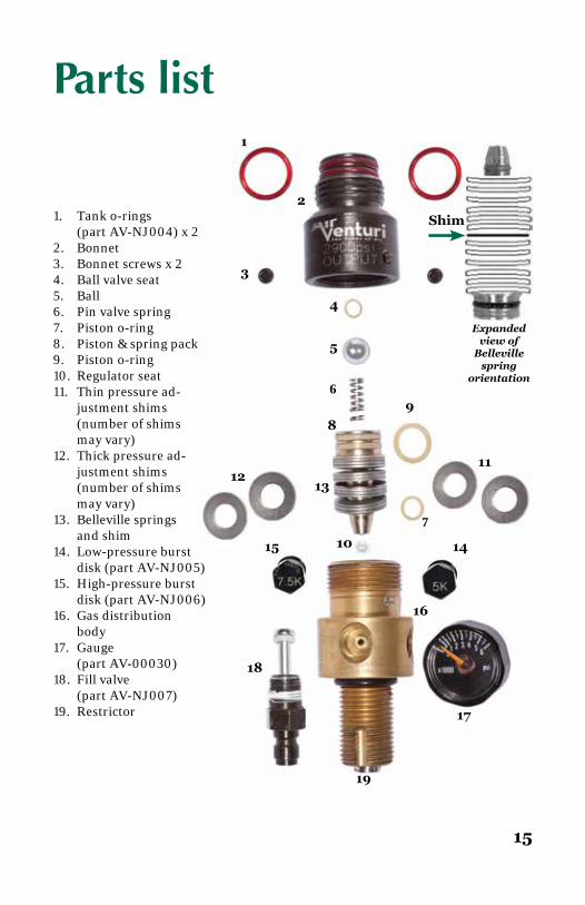
Parts list
Shim
Expanded view of
Belleville spring
orientation
1
2
3
4
5
6
7
89
1312
10
11
15 14
18
19
16
17
1. Tank o-rings (part AV-NJ004) x 22. Bonnet3. Bonnet screws x 24. Ball valve seat5. Ball6. Pin valve spring7. Piston o-ring8. Piston & spring pack9. Piston o-ring10. Regulator seat11. Thin pressure ad- justment shims (number of shims may vary)12. Thick pressure ad- justment shims (number of shims may vary)13. Belleville springs and shim14. Low-pressure burst disk (part AV-NJ005)15. High-pressure burst disk (part AV-NJ006)16. Gas distribution body17. Gauge (part AV-00030)18. Fill valve (part AV-NJ007)19. Restrictor

336U BLK
Air Venturi5135 Naiman Parkway
Solon, OH 44139216-220-1180
Copyright ©2014 Air Venturi. All rights reserved. 02/03/14