carbon steel 900 pumps - samki eng · packing nut/wet-cup 12 ... with king air motor (55 gallon/200...
TRANSCRIPT

308353Rev. E
First choice whenquality counts.�
INSTRUCTIONS-PARTS LIST
INSTRUCTIONS
This manual contains importantwarnings and information.READ AND KEEP FOR REFERENCE.
CARBON STEEL
Dura-Flo� 900 PumpsWith Severe-Duty Rod and Cylinder
Refer to page 2 for a List of Models; page 3 for the Table of Contents.
������
Model 237279
������
Model 236475
GRACO INC. P.O. BOX 1441 MINNEAPOLIS, MN 55440–1441�COPYRIGHT 1994, GRACO INC.
Graco Inc. is registered to I.S. EN ISO 9001

� ������
List of Models
Pump Part No.and Series Pump Model
DisplacementPump Part No. and Series Ratio
Maximum Fluid Working Pressure
Maximum Air/Hydraulic Input Pressure
237279,Series A
Senator� ���������� �� 17:1 11 MPa, 117 bar(1700 psi)
0.7 MPa, 7 bar (100 psi)
237284,Series A
Bulldog� ���������� �� 28:1 19 MPa, 193 bar(2800 psi)
0.7 MPa, 7 bar (100 psi)
237292,Series A
Reduced IcingQuiet Bulldog�
���������� �� 28:1 19 MPa, 193 bar(2800 psi)
0.7 MPa, 7 bar (100 psi)
236475,Series A
King� ���������� �� 56:1 34 MPa, 345 bar(5000 psi)
0.6 MPa, 6 bar (90 psi)
240946,Series A
Quiet King� ���������� �� 56:1 34 MPa, 345 bar(5000 psi)
0.6 MPa, 6 bar (90 psi)
237278,Series A
Reduced IcingQuiet King�
���������� �� 56:1 34 MPa, 345 bar(5000 psi)
0.6 MPa, 6 bar (90 psi)
237283,Series A
King��(55 gallon size)
���������� �� 56:1 34 MPa, 345 bar(5000 psi)
0.6 MPa, 6 bar (90 psi)
237290,Series A
Viscount�(hydraulic)
���������� �� 3.5:1 34 MPa, 345 bar(5000 psi)
9.9 MPa, 99 bar (1428 psi)hydraulic pressure
917028,Series A
Viscount��II(hydraulic)
���������� �� 3.5:1 34 MPa, 345 bar(5000 psi)
9.9 MPa, 99 bar (1428 psi)hydraulic pressure

������ �
Table of ContentsList of Models 2. . . . . . . . . . . . . . . . . . . . . . . . . . . . . . . . Warnings 4. . . . . . . . . . . . . . . . . . . . . . . . . . . . . . . . . . . . . Manual Change Summary 51. . . . . . . . . . . . . . . . . . . . . Installation 7. . . . . . . . . . . . . . . . . . . . . . . . . . . . . . . . . . .
All Pumps 7. . . . . . . . . . . . . . . . . . . . . . . . . . . . . . . . . General Information 7. . . . . . . . . . . . . . . . . . . . . . . . . Grounding 7. . . . . . . . . . . . . . . . . . . . . . . . . . . . . . . . . Air-Powered Pumps 8. . . . . . . . . . . . . . . . . . . . . . . . . System Accessories 8. . . . . . . . . . . . . . . . . . . . . . . . Typical Air-Powered Installation 9. . . . . . . . . . . . . . . Hydraulic-Powered Pumps 10. . . . . . . . . . . . . . . . . . System Accessories 10. . . . . . . . . . . . . . . . . . . . . . . Typical Hydraulic-Powered Installation 11. . . . . . . .
Operation/Maintenance 12. . . . . . . . . . . . . . . . . . . . . . . All Pumps 12. . . . . . . . . . . . . . . . . . . . . . . . . . . . . . . . Pressure Relief Procedure 12. . . . . . . . . . . . . . . . . . Packing Nut/Wet-Cup 12. . . . . . . . . . . . . . . . . . . . . . Air-Powered Pumps 13. . . . . . . . . . . . . . . . . . . . . . . . Flush the Pump Before First Use 13. . . . . . . . . . . . Starting and Adjusting the Pump 13. . . . . . . . . . . . . Shutdown and Care of the Pump 14. . . . . . . . . . . . . Flushing 14. . . . . . . . . . . . . . . . . . . . . . . . . . . . . . . . . . Hydraulic-Powered Pumps 15. . . . . . . . . . . . . . . . . . Flushing the Pump Before First Use 15. . . . . . . . . . Starting and Adjusting the Pump 15. . . . . . . . . . . . . Shutdown and Care of the Pump 16. . . . . . . . . . . . . Flushing 16. . . . . . . . . . . . . . . . . . . . . . . . . . . . . . . . . .
Troubleshooting Chart 17. . . . . . . . . . . . . . . . . . . . . . . Service 18. . . . . . . . . . . . . . . . . . . . . . . . . . . . . . . . . . . . . .
Required Tools 18. . . . . . . . . . . . . . . . . . . . . . . . . . . . Disconnecting the Displacement Pump 18. . . . . . . Reconnecting the Displacement Pump 18. . . . . . . . Displacement Pump Service 20. . . . . . . . . . . . . . . .
Parts 26. . . . . . . . . . . . . . . . . . . . . . . . . . . . . . . . . . . . . . . . Part No. 236475 Pump, Series A, 56:1 Ratio with King Air Motor 26. . . . . . . . . . . . . . . . . . . . . . . . . Part No. 237278 Pump, Series A, 56:1 Ratio with Reduced Icing Quiet King Air Motor 26. . . . . . Part No. 237283 Pump, Series A, 56:1 Ratio with King Air Motor (55 gallon/200 liter size) 27. . .
Part No. 240946 Pump, Series A, 56:1 Ratio with Quiet King Air Motor 28. . . . . . . . . . . . . . . . . . . Part No. 237279 Pump, Series A, 17:1 Ratio with Senator Air Motor 28. . . . . . . . . . . . . . . . . . . . . . Part No. 237284 Pump, Series A, 28:1 Ratio with Bulldog Air Motor 29. . . . . . . . . . . . . . . . . . . . . . Part No. 237292 Pump, Series A, 28:1 Ratio with Reduced Icing Quiet Bulldog Air Motor 29. . . . Part No. 237290 Pump, Series A, with Viscount Hydraulic Motor 30. . . . . . . . . . . . . . . Part No. 917028 Pump, Series A, with Viscount II Hydraulic Motor 31. . . . . . . . . . . . . . Common Displacement Pump Parts 32. . . . . . . . . .
Packing Kits 33. . . . . . . . . . . . . . . . . . . . . . . . . . . . . . . . . Leather Packing Kit 237163, for Standard Displacement Pump 236466, Series A 33. . . . . . . . Teflon Packing Kit 237164, for Optional Displacement Pump 236896, Series A 33. . . . . . . . UHMWPE and Leather Packing Kit237165 (Optional) 33. . . . . . . . . . . . . . . . . . . . . . . . . . UHMWPE and Teflon Packing Kit 237709, for Standard Displacement Pump240682, Series A 34. . . . . . . . . . . . . . . . . . . . . . . . . .
Technical Data 36. . . . . . . . . . . . . . . . . . . . . . . . . . . . . . . Model 236475 and 237283 King Pumps 36. . . . . . . Model 240946 Quiet King and 237278 Reduced Icing Quiet King Pumps 38. . . . . . . . . . . . Model 237284 Bulldog Pump 40. . . . . . . . . . . . . . . . Model 237292 Reduced Icing Quiet Bulldog Pump 42. . . . . . . . . . . . . . . . . . . . . . . . . . . . . Model 237279 Senator Pump 44. . . . . . . . . . . . . . . . Model 237290 Viscount Pump 46. . . . . . . . . . . . . . . Model 917028 Viscount II Pump 48. . . . . . . . . . . . .
Dimensions 50. . . . . . . . . . . . . . . . . . . . . . . . . . . . . . . . . . Pump Dimensions 50. . . . . . . . . . . . . . . . . . . . . . . . . Mounting Hole Layout 50. . . . . . . . . . . . . . . . . . . . . .
Graco Standand Warranty 52. . . . . . . . . . . . . . . . . . . . Graco Phone Number 52. . . . . . . . . . . . . . . . . . . . . . . .

� ������
SymbolsWarning Symbol
WARNING�his symbol alerts you to the possibility of seriousinjury or death if you do not follow the instructions.
Caution Symbol
CAUTIONThis symbol alerts you to the possibility of damage toor destruction of equipment if you do not follow theinstructions.
WARNING
INSTRUCTIONS
EQUIPMENT MISUSE HAZARD
Equipment misuse can cause the equipment to rupture or malfunction and result in serious injury.
� This equipment is for professional use only.
� Read all instruction manuals, tags, and labels before operating the equipment.
� Use the equipment only for its intended purpose. If you are uncertain about usage, call your Gracodistributor.
� Do not alter or modify this equipment.
� Check equipment daily. Repair or replace worn or damaged parts immediately.
� Do not exceed the maximum working pressure of the lowest rated system component. Refer to theTechnical Data on pages 36–46 for the maximum working pressure of this equipment.
� Use fluids and solvents which are compatible with the equipment wetted parts. Refer to the Tech-nical Data section of all equipment manuals. Read the fluid and solvent manufacturer’s warnings.
� Do not use hoses to pull equipment.
� Route hoses away from traffic areas, sharp edges, moving parts, and hot surfaces. Do not exposeGraco hoses to temperatures above 82�C (180�F) or below –40�C (–40�F).
� Wear hearing protection when operating this equipment.
� Do not lift pressurized equipment.
� Comply with all applicable local, state, and national fire, electrical, and safety regulations.

������ �
WARNINGINJECTION HAZARD
Spray from the gun, leaks or ruptured components can inject fluid into your body and cause extremelyserious injury, including the need for amputation. Fluid splashed in the eyes or on the skin can alsocause serious injury.
� Fluid injected into the skin might look like just a cut, but it is a serious injury. Get immediate medi-cal attention.
� Do not point the gun at anyone or at any part of the body.
� Do not put your hand or fingers over the spray tip.
� Do not stop or deflect leaks with your hand, body, glove or rag.
� Do not “blow back” fluid; this is not an air spray system.
� Always have the tip guard and the trigger guard on the gun when spraying.
� Check the gun diffuser operation weekly. Refer to the gun manual.
� Be sure the gun trigger safety operates before spraying.
� Lock the gun trigger safety when you stop spraying.
� Follow the Pressure Relief Procedure on page 12 if the spray tip clogs and before cleaning,checking or servicing the equipment.
� Tighten all fluid connections before operating the equipment.
� Check the hoses, tubes, and couplings daily. Replace worn or damaged parts immediately. Do not repair high pressure couplings; you must replace the entire hose.
� Fluid hoses must have spring guards on both ends, to help protect them from rupture caused bykinks or bends near the couplings.
MOVING PARTS HAZARD
Moving parts, such as the air motor piston, can pinch or amputate your fingers.
� Keep clear of all moving parts when starting or operating the pump.
� Before servicing the equipment, follow the Pressure Relief Procedure on page 12 to prevent theequipment from starting unexpectedly.
� ������
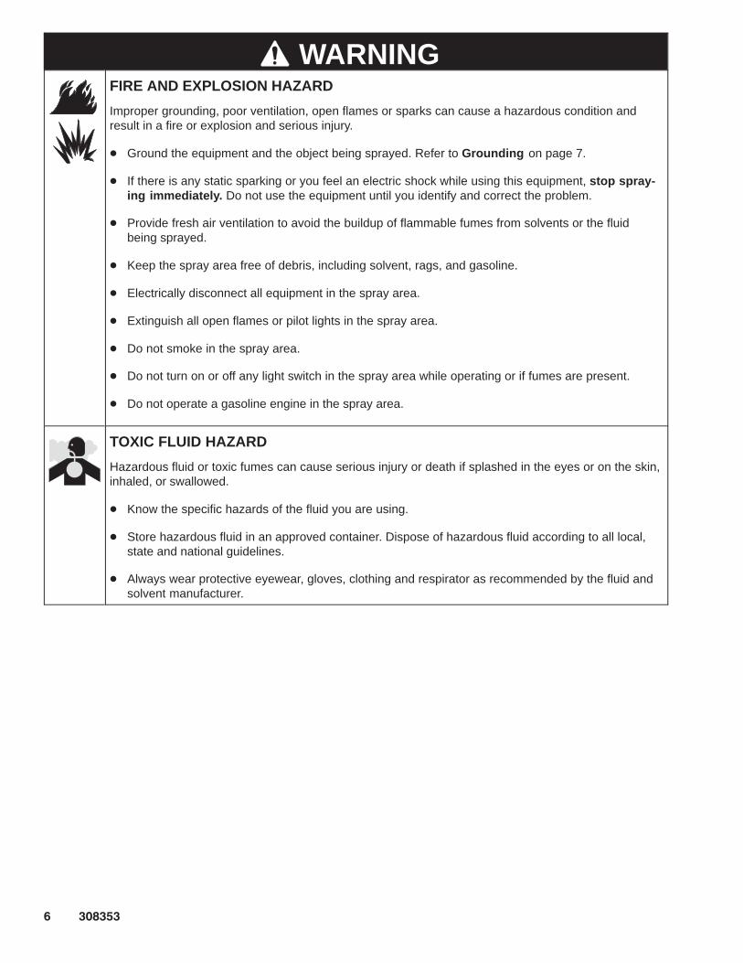
WARNINGFIRE AND EXPLOSION HAZARD
Improper grounding, poor ventilation, open flames or sparks can cause a hazardous condition andresult in a fire or explosion and serious injury.
� Ground the equipment and the object being sprayed. Refer to Grounding on page 7.
� If there is any static sparking or you feel an electric shock while using this equipment, stop spray-ing immediately. Do not use the equipment until you identify and correct the problem.
� Provide fresh air ventilation to avoid the buildup of flammable fumes from solvents or the fluidbeing sprayed.
� Keep the spray area free of debris, including solvent, rags, and gasoline.
� Electrically disconnect all equipment in the spray area.
� Extinguish all open flames or pilot lights in the spray area.
� Do not smoke in the spray area.
� Do not turn on or off any light switch in the spray area while operating or if fumes are present.
� Do not operate a gasoline engine in the spray area.
TOXIC FLUID HAZARD
Hazardous fluid or toxic fumes can cause serious injury or death if splashed in the eyes or on the skin,inhaled, or swallowed.
� Know the specific hazards of the fluid you are using.
� Store hazardous fluid in an approved container. Dispose of hazardous fluid according to all local,state and national guidelines.
� Always wear protective eyewear, gloves, clothing and respirator as recommended by the fluid andsolvent manufacturer.

������ �
Installation(ALL PUMPS)
General Information
NOTE: Reference numbers and letters in parenthesesin the text refer to the callouts in the figures and theparts drawing.
NOTE: Always use Genuine Graco Parts and Acces-sories, available from your Graco distributor. Refer toProduct Data Sheet, Form No. 305715 (SenatorPumps), Form No. 305716 (Bulldog Pumps), Form No.305717 (King Pumps), and Form No. 305718 (ViscountPumps). If you supply your own accessories, be surethey are adequately sized and pressure rated for yoursystem.
Grounding
WARNINGFIRE AND EXPLOSION HAZARDBefore operating the pump, ground thesystem as explained below. Also readthe section FIRE AND EXPLOSIONHAZARD on page 6.
1. Pump: use a ground wire and clamp. See Fig. 1.Loosen the grounding lug locknut (W) and washer(X). Insert one end of a 1.5 mm� (12 ga) minimumground wire (Y) into the slot in lug (Z) and tightenthe locknut securely. Connect the other end of thewire to a true earth ground. Order Part No. 237569Ground Wire and Clamp.
Fig. 1
W
XY
Z
����
2. Air, hydraulic, and fluid hoses: use only electricallyconductive hoses.
3. Air compressor or hydraulic power supply: followmanufacturer’s recommendations.
4. Spray gun: ground through connection to a prop-erly grounded fluid hose and pump.
5. Fluid supply container: follow your local code.
6. Object being sprayed: follow your local code.
7. Solvent pails used when flushing: follow your localcode. Use only metal pails, which are conductive,placed on a grounded surface. Do not place thepail on a nonconductive surface, such as paper orcardboard, which interrupts the grounding continu-ity.
8. To maintain grounding continuity when flushing orrelieving pressure, hold a metal part of the spraygun firmly to the side of a grounded metal pail,then trigger the gun.

� ������
Installation(AIR-POWERED PUMPS)
System Accessories
Fig. 2 is only a guide for selecting and installing sys-tem components and accessories. Contact your Gracodistributor for assistance in designing a system to suityour particular needs.
WARNINGA bleed-type master air valve (E) and a fluid drainvalve (M) are required in your system. Theseaccessories help reduce the risk of serious injury,including fluid injection and splashing of fluid in theeyes or on the skin, and injury from moving parts ifyou are adjusting or repairing the pump.
The bleed-type master air valve relieves air trappedbetween this valve and the pump after the air isshut off. Trapped air can cause the pump to cycleunexpectedly. Locate the valve close to the pump.Order Part No. 107141.
The fluid drain valve assists in relieving fluid pres-sure in the displacement pump, hose, and gun.Triggering the gun to relieve pressure may not besufficient. Order Part No. 210658.
Air and Fluid Hoses
Be sure all air hoses (H) and fluid hoses (N and P) areproperly sized and pressure-rated for your system.Use only electrically conductive hoses. Fluid hosesmust have spring guards on both ends. Use a whiphose (P) and a swivel (R) between the main fluid hose(N) and the gun (S) to allow freer gun movement.
Mounting Accessories
Mount the pump (A) to suit the type of installationplanned. Fig. 2 illustrates a cart mount system. Pumpdimensions and the mounting hole layout are shownon page 50.
Air Line Accessories
Install the following accessories in the locations shownin Fig. 2, using adapters as necessary:
� An air line lubricator (D) provides automatic airmotor lubrication.
� A bleed-type master air valve (E) is required inyour system to relieve air trapped between it andthe air motor when the valve is closed (see theWARNING at left). Be sure the bleed valve is easi-ly accessible from the pump, and is located down-stream from the air regulator.
� An air regulator (F) controls pump speed and out-let pressure by adjusting the air pressure to thepump. Locate the regulator close to the pump, butupstream from the bleed-type master air valve.
� A pump runaway valve (C ) senses when thepump is running too fast and automatically shutsoff the air to the motor. A pump which runs too fastcan be seriously damaged.
� An air manifold (G) has a 3/4 npsm(f) swivel airinlet. It mounts to the pump support bracket, andprovides ports for connecting lines to air-poweredaccessories.
� An air line filter (J) removes harmful dirt andmoisture from the compressed air supply. Also,install a drain valve (W) at the bottom of each airline drop, to drain off moisture.
� A second bleed-type air valve (K) isolates the airline accessories for servicing. Locate upstreamfrom all other air line accessories.
Fluid Line Accessories
Install the following accessories in the locations shownin Fig. 2, using adapters as necessary:
� A fluid filter (L) with a 60 mesh (250 micron)stainless steel element, to filter particles from thefluid as it leaves the pump.
� A fluid drain valve (M), which is required in yoursystem, helps relieve fluid pressure in the hoseand gun (see the WARNING at left).
� A gun (S) dispenses the fluid. The gun shown inFig. 2 is an airless spray gun for light to mediumviscosity fluids.
� A gun swivel (R) allows freer gun movement.
� A suction kit (T) allows the pump to draw fluidfrom a supply container.

������ �
Installation
������
Fig. 2
KEY
A PumpB CartC Pump Runaway Valve (location)D Air Line Lubricator (location)E Bleed-Type Master Air Valve
(required, for pump)F Pump Air RegulatorG Air Manifold
H Electrically Conductive Air Supply HoseJ Air Line FilterK Bleed-Type Master Air Valve
(for accessories)L Fluid FilterM Fluid Drain Valve (required)N Electrically Conductive
Fluid Supply Hose
P Fluid Whip HoseR Gun SwivelS Airless Spray GunT Suction KitY Ground Wire and Clamp
(required; see page 7for installation instructions)
TYPICAL AIR-POWERED INSTALLATION
A
B
C
D
E
F
GH
J K
M
N
P
Y
MAIN AIR LINE
L
R
S
T

�� ������
Installation(HYDRAULIC-POWERED PUMPS)
CAUTIONKeep the hydraulic supply system clean at all times.Be sure that all hydraulic fluid lines are absolutelyclean. Blow out the lines with air and flush thoroughlywith solvent before connecting to the hydraulicmotor, to avoid introducing harmful contaminants intothe motor. Plug the hydraulic lines immediately whenthey are disconnected.
Do not exceed 37.8 liter/min (10 gpm) hydraulic oilvolume to the motor, to avoid stalling the pump.
For optimum pump performance, keep the tempera-ture of the hydraulic oil below 54�C (130�F).
System Accessories
Fig. 3 is only a guide for selecting and installing sys-tem components and accessories. Contact your Gracodistributor for assistance in designing a system to suityour particular needs.
WARNINGA fluid drain valve (M) is required in your system.This accessory helps reduce the risk of seriousbodily injury, including fluid injection and splashingof fluid in the eyes or on the skin, and injury frommoving parts if you are adjusting or repairing thepump.
The fluid drain valve assists in relieving fluid pres-sure in the displacement pump, hose, and gun.Triggering the gun to relieve pressure may not besufficient. Order Part No. 210658.
Mounting Accessories
Mount the pump (A) to suit the type of installationplanned. Fig. 3 illustrates a wall mount system. Pumpdimensions and the mounting hole layout are shownon page 50.
Filters
Be sure your hydraulic power supply is equipped with asuction filter to the hydraulic pump and a system returnline filter (AA) of 10 micron size.
Carefully follow the manufacturer’s recommendationson reservoir and filter cleaning, and periodic changesof hydraulic fluid. Use only Graco-approved hydraulicoil. Order Part No. 169236 for 19 liter (5 gal.) or PartNo. 207428 for 3.8 liter (1 gal.) power supplies.
Hydraulic Lines
The motor has a 3/4 npt(f) hydraulic oil supply fitting,and a 1” npt(f) hydraulic oil return fitting. Use a mini-mum 13 mm (1/2 in.) ID hydraulic supply line, and aminimum 22 mm (7/8 in.) ID return line.
On the hydraulic supply line (C), install the followingaccessories in the order shown in Fig. 3, using adapt-ers as necessary:
� A shutoff valve (U ) isolates the pump for service.
� A fluid pressure gauge (F) to monitor hydraulicoil pressure to the motor and to avoid overpressur-izing the motor or displacement pump, and a pres-sure- and temperature-compensated flow con-trol valve (G) to prevent the motor from runningtoo fast and possibly damaging itself.
� A pressure reducing valve (H), with a drain line(E) run directly to the hydraulic return line (D).
� An accumulator (J) to reduce the hammering ef-fect caused by the motor reversing direction.
� A shutoff valve (V ) isolates the pump for service.
� A filter (AA ) of 10 micron size.
Hydraulic Motor Drip Pan
The hydraulic motor has a drip pan to collect anyleakage. Connect a 6 mm (1/4 in.) ID drain line (K) tothe barbed fitting on the drip pan, and place the freeend in a container to receive the drainage.
Fluid Supply Hoses
Be sure all fluid hoses (N and P) are properly sizedand pressure-rated for your system. Use only electri-cally conductive hoses. Fluid hoses must have springguards on both ends. Use a whip hose (P) and aswivel (R) between the main fluid hose (N) and the gun(S) to allow freer gun movement.

������ ��
Installation(HYDRAULIC-POWERED PUMPS)
Fluid Line Accessories
Install the following accessories in the locations shownin Fig. 3, using adapters as necessary:
� A fluid filter (L) with a 60 mesh (250 micron)stainless steel element, to filter particles from thefluid as it leaves the pump.
� A fluid drain valve (M), which is required in yoursystem, helps relieve fluid pressure in the hoseand gun (see the WARNING on page 10).
� A gun (S) dispenses the fluid. The gun shown inFig. 3 is an airless spray gun for light to mediumviscosity fluids.
� A gun swivel (R) allows freer gun movement.
� A suction kit (T) allows the pump to draw fluidfrom a supply container.
KEY
A PumpB Wall BracketC Hydraulic Supply LineD Hydraulic Return LineE Drain Line (from pressure reducing valve)F Pressure GaugeG Flow Control ValveH Pressure Reducing ValveJ AccumulatorK Drain Line (from motor drip pan)L Fluid FilterM Fluid Drain Valve (required)N Electrically Conductive
Fluid Supply HoseP Fluid Whip HoseR Gun SwivelS Airless Spray GunT Drum Suction KitU Hydraulic Supply Line Shutoff ValveV Hydraulic Return Line Shutoff ValveY Ground Wire (required, see page 7 for
installation instructions)AA Hydraulic Return Line Filter
������
Fig. 3
A
B
D
E
F
G
HJ
K
M
N
P
Y
200 LITER (55 GAL.)DRUM
L
R
S
T
U
C
V
HYDRAULICPOWER SUPPLY
DRAINAGECONTAINER
AA
TYPICAL HYDRAULIC-POWERED INSTALLATION

�� ������
Operation/Maintenance(ALL PUMPS)
Pressure Relief Procedure
WARNINGINJECTION HAZARDThe system pressure must be manuallyrelieved to prevent the system fromstarting or spraying accidentally. Fluid
under high pressure can be injected through theskin and cause serious injury. To reduce the risk ofan injury from injection, splashing fluid, or movingparts, follow the Pressure Relief Procedurewhenever you:
� are instructed to relieve the pressure,� stop spraying,� check or service any of the system equipment,� or install or clean the spray tips.
1. Lock the gun trigger safety.
2. Shut off the air or hydraulic supply to the pump.
3. In air-powered systems, close the bleed-typemaster air valve (required in your system).
In hydraulic-powered systems, close the hydraulicsupply line valve first, then the return line valve.
4. Unlock the gun trigger safety.
5. Hold a metal part of the gun firmly to the side of agrounded metal pail, and trigger the gun to relievepressure.
6. Lock the gun trigger safety.
7. Open the drain valve (required in your system),having a container ready to catch the drainage.
8. Leave the drain valve open until you are ready tospray again.
If you suspect that the spray tip or hose is completelyclogged, or that pressure has not been fully relievedafter following the steps above, very slowly loosen thetip guard retaining nut or hose end coupling and relievepressure gradually, then loosen completely. Now clearthe tip or hose.
Packing Nut/Wet-Cup
Before starting, fill the packing nut (2) 1/3 full withGraco Throat Seal Liquid (TSL) or compatible solvent.See Fig. 4.
WARNINGTo reduce the risk of serious injury whenever youare instructed to relieve pressure, always follow thePressure Relief Procedure at left.
The packing nut is torqued at the factory and is readyfor operation. If it becomes loose and there is leakingfrom the throat packings, relieve pressure, thentorque the nut to 128–156 N.m (95–115 ft-lb) using thesupplied wrench (110). Do this whenever necessary.Do not overtighten the packing nut.
������
Fig. 4
1102
�
�
Model 236475 Shown
Torque to 128–156 N.m (95–115 ft-lb)

������ ��
Operation/Maintenance(AIR-POWERED PUMPS)
Flush the Pump Before First Use
The pump is tested with lightweight oil, which is left into protect the pump parts. If the fluid you are usingmay be contaminated by the oil, flush it out with acompatible solvent. See Flushing on page 14.
Starting and Adjusting the Pump
1. See Fig. 2 on page 9. Connect the suction kit (T)to the pump’s fluid inlet. Place the tube into thefluid supply.
2. Close the air regulator (F).
3. Open the pump’s bleed-type master air valve (E).
4. Hold a metal part of of the gun (S) firmly to theside of a grounded metal pail and hold the triggeropen.
5. Slowly open the regulator until the pump starts.
6. Cycle the pump slowly until all air is pushed outand the pump and hoses are fully primed.
7. Release the gun trigger and lock the trigger safety.The pump should stall against pressure.
8. If the pump fails to prime properly, open the drainvalve (M). Use the drain valve as a priming valveuntil the fluid flows from the valve. Close the valve.
NOTE: When changing fluid containers with the hoseand gun already primed, open the drain valve (M) tohelp prime the pump and vent air before it enters thehose. Close the drain valve when all air is eliminated.
CAUTIONDo not allow the pump to run dry. It will quicklyaccelerate to a high speed, causing damage. If yourpump is running too fast, stop it immediately andcheck the fluid supply. If the container is empty andair has been pumped into the lines, refill the con-tainer and prime the pump and the lines, or flush andleave it filled with a compatible solvent. Eliminate allair from the fluid system.
9. With the pump and lines primed, and with ade-quate air pressure and volume supplied, the pumpwill start and stop as you open and close the gun.In a circulating system, the pump will speed up orslow down on demand, until the air supply is shutoff.
WARNINGCOMPONENT RUPTURE HAZARDTo reduce the risk of overpressurizingyour system, which could cause compo-nent rupture and serious injury, never
exceed the specified Maximum Incoming Air Pres-sure to the pump (see the Technical Data, onpages 36–44).
10. Use the air regulator (F) to control pump speedand fluid pressure. Always use the lowest airpressure necessary to get the desired results.Higher pressures cause premature tip and pumpwear.

�� ������
Operation/Maintenance(AIR-POWERED PUMPS)
Shutdown and Care of the Pump
WARNINGTo reduce the risk of serious injury whenever youare instructed to relieve pressure, always follow thePressure Relief Procedure on page 12.
For overnight shutdown, stop the pump at the bottomof its stroke to prevent fluid from drying on the ex-posed displacement rod and damaging the throatpackings. Relieve the pressure.
Always flush the pump before the fluid dries on thedisplacement rod. See Flushing below.
Flushing
WARNINGFIRE AND EXPLOSION HAZARDBefore flushing, read the section FIREAND EXPLOSION HAZARD on page6. Be sure the entire system and flush-ing pails are properly grounded. Refer toGrounding on page 7.
Flush with a fluid that is compatible with the fluid youare pumping and with the wetted parts in your system.Check with your fluid manufacturer or supplier forrecommended flushing fluids and flushing frequency.Always flush the pump before fluid dries on the dis-placement rod.
CAUTIONNever leave water or water-base fluid in the pumpovernight. If you are pumping water-base fluid, flushwith water first, then with a rust inhibitor such asmineral spirits. Relieve the pressure, but leave therust inhibitor in the pump to protect the parts fromcorrosion.
WARNINGTo reduce the risk of serious injury whenever youare instructed to relieve pressure, always follow thePressure Relief Procedure on page 12.
1. Relieve the pressure.
2. Remove the spray tip from the gun.
3. Hold a metal part of the gun firmly to the side of agrounded metal pail.
4. Start the pump. Always use the lowest possiblefluid pressure when flushing.
5. Trigger the gun.
6. Flush the system until clear solvent flows from thegun.
7. Relieve the pressure.

������ ��
Operation/Maintenance(HYDRAULIC-POWERED PUMPS)
Flush the Pump Before First Use
The pump is tested with lightweight oil, which is left into protect the pump parts. If the fluid you are usingmay be contaminated by the oil, flush it out with acompatible solvent. See Flushing on page 16.
Starting and Adjusting the Pump
1. Refer to Fig. 3 on page 11. Connect the suction kit(T) to the pump’s fluid inlet, and place the tube intothe fluid supply.
2. Check the hydraulic fluid level before each use,and add fluid as necessary.
3. Make certain that the supply line shutoff valve (U)and the return line shutoff valve (V) are closed.
4. Start the hydraulic power supply.
5. Hold a metal part of the gun (S) firmly to the sideof a grounded metal pail and hold the trigger open.
6. Open the return line shutoff valve (V) first, thenslowly open the supply line shutoff valve (U).
7. Cycle the pump slowly until all air is pushed outand the pump and hoses are fully primed.
8. Release the gun trigger and lock the trigger safety.The pump should stall against pressure.
9. If the pump fails to prime properly, open the drainvalve (M). Use the drain valve as a priming valveuntil the fluid flows from the valve. Close the valve.
NOTE: When changing fluid containers with the hoseand gun already primed, open the drain valve (M) tohelp prime the pump and vent air before it enters thehose. Close the drain valve when all air is eliminated.
10. With the pump and lines primed, and with ade-quate hydraulic volume supplied, the pump willstart and stop as you open and close the gun. In acirculating system, the pump will speed up or slowdown on demand, until the hydraulic power supplyis shut off.
11. Use the fluid pressure gauge (F) and flow controlvalve (G) to control the pump speed and the fluidoutlet pressure. Always use the lowest hydraulicflow and pressure necessary to get the desiredresults. Higher pressures cause premature tip/noz-zle and pump wear.
WARNINGCOMPONENT RUPTURE HAZARDTo reduce the risk of overpressurizingyour system, which could cause compo-nent rupture and serious injury, never
exceed the specified Maximum Incoming Air Pres-sure to the pump (see the Technical Data on page46).
To prevent overpressurizing the hydraulic motor orits seals, always shut off the supply line valve (U)first, then shut off the return line valve (V).
CAUTIONDo not allow the hydraulic oil temperature to exceed54�C (130�F). The pump seals will wear faster andleakage may occur if the pump is operated at higheroil temperatures.

�� ������
Operation/Maintenance(HYDRAULIC-POWERED PUMPS)
Shutdown and Care of the Pump
WARNINGTo reduce the risk of serious injury whenever youare instructed to relieve pressure, always follow thePressure Relief Procedure on page 12.
For overnight shutdown, stop the pump at the bottomof its stroke to prevent fluid from drying on the ex-posed displacement rod and damaging the throatpackings. Relieve the pressure.
Always flush the pump before the fluid dries on thedisplacement rod. See Flushing below.
Flushing
WARNINGFIRE AND EXPLOSION HAZARDBefore flushing, read the section FIREAND EXPLOSION HAZARD on page6. Be sure the entire system and flush-ing pails are properly grounded. Refer toGrounding on page 7.
Flush with a fluid that is compatible with the fluid youare pumping and with the wetted parts in your system.Check with your fluid manufacturer or supplier forrecommended flushing fluids and flushing frequency.Always flush the pump before fluid dries on the dis-placement rod.
CAUTIONNever leave water or water-base fluid in the pumpovernight. If you are pumping water-base fluid, flushwith water first, then with a rust inhibitor such asmineral spirits. Relieve the pressure, but leave therust inhibitor in the pump to protect the parts fromcorrosion.
WARNINGTo reduce the risk of serious injury whenever youare instructed to relieve pressure, always follow thePressure Relief Procedure on page 12.
1. Relieve the pressure.
2. Remove the spray tip from the gun.
3. Hold a metal part of the gun firmly to the side of agrounded metal pail.
4. Start the pump. Always use the lowest possiblefluid pressure when flushing.
5. Trigger the gun.
6. Flush the system until clear solvent flows from thegun.
7. Relieve the pressure.

������ ��
Troubleshooting Chart
WARNINGTo reduce the risk of serious injury whenever youare instructed to relieve pressure, always follow thePressure Relief Procedure on page 12.
1. Relieve the pressure.
2. Check all possible causes and problems beforedisassembling the pump.
PROBLEM CAUSE SOLUTION
The pump fails to oper-ate.
Restricted air/hydraulic line or an inade-quate air/hydraulic supply; closed orclogged valves.
Clear the line; increase the air/hydraulic supply.Check that the valves are open.
Obstructed fluid hose or gun;the fluid hose ID is too small.
Open, clear*; use a hose with a larger ID.
Fluid has dried on the displacement rod. Clean the rod; always stop the pump at the bottomof its stroke;keep the wet-cup 1/3 filled with a compatible sol-vent.
Dirty, worn, or damaged motor parts. Clean or repair; see the separate motor manual.
The pump operates,but the output is low onboth strokes.
Restricted air/hydraulic line or an inade-quate air/hydraulic supply; closed orclogged valves.
Clear the line; increase the air/hydraulic supply.Check that the valves are open.
Obstructed fluid hose or gun;the fluid hose ID is too small.
Open, clear*; use a hose with a larger ID.
Worn packings in the displacementpump.
Replace the packings.
The pump operates,but the output is low onthe downstroke.
Held open or worn intake valve. Clear the valve; service.
The pump operates,but the output is low onthe upstroke.
Held open or worn piston valve or pack-ings.
Clear the valve; replace the packings.
Erratic or acceleratedpump speed.
Exhausted fluid supply. Refill the supply and prime the pump.
Held open or worn piston valve or pack-ings.
Clear the valve; replace the packings.
Held open or worn intake valve. Clear the valve; service.
* To determine if the fluid hose or gun is obstructed, follow the Pressure Relief Procedure on page 12. Discon-nect the fluid hose and place a container at the pump fluid outlet to catch any fluid. Turn on the air or hydraulicpower just enough to start the pump. If the pump starts when the air or hydraulic power is turned on, the ob-struction is in the fluid hose or gun.
NOTE: If you experience air motor icing, call your Graco distributor.

�� ������
ServiceRequired Tools� Set of adjustable wrenches� Large pipe wrench� ��������� ����
� Torque wrench� Rubber mallet� O-ring pick� Large vise� Thread lubricant� Thread sealant
Disconnecting the Displacement Pump1. Flush the pump, if possible. Stop the pump at the
bottom of its stroke.
WARNINGTo reduce the risk of serious injury whenever youare instructed to relieve pressure, always follow thePressure Relief Procedure on page 12.
2. Relieve the pressure.
3. Disconnect the air or hydraulic hose and the fluidhose. Plug all hydraulic hoses immediately, toprevent contamination of the hydraulic system.
4. Disconnect the displacement pump (109) from themotor (101) as follows. Note the relative position ofthe pump’s fluid outlet (U) to the air (V) or hydrau-lic inlet of the motor. If the motor does not requireservicing, leave it attached to its mounting. SeeFig. 5.
CAUTIONBe sure to use at least two people when lifting,moving, or disconnecting the pump. This pump is tooheavy for one person. If you are disconnecting thedisplacement pump from a motor which is stillmounted (for example, on a wall bracket), be sure tosupport the displacement pump while it is beingdisconnected, to prevent it from falling and causinginjury or property damage. Do this by securely brac-ing the pump, or by having at least two people hold itwhile another disconnects it.
If the pump is mounted on a cart, slowly tip the cartbackward until the handle rests on the ground, thendisconnect the displacement pump.
5. Using an adjustable wrench (or hammer andpunch), unscrew the coupling nut (106) from themotor shaft (W). Take care not to lose or drop thecoupling collars (107). See Fig. 5.
NOTE: On Model 237283, disconnect the riser tube(119) at either the elbow (120) or the connector (118).See the Parts Drawing on page 27.
6. Hold the tie rod flats with a wrench to keep therods from turning. Unscrew the nuts (108) from thetie rods (105). Carefully remove the displacementpump (109) from the motor (101).
7. Refer to page 20 for displacement pump service.To service the air or hydraulic motor, refer to theseparate motor manual, supplied.
Reconnecting the Displacement Pump
1. Make sure the coupling nut (106) and the couplingcollars (107) are in place on the displacement rod(1). See Fig. 5.
2. Use at least two people to hold the displacementpump while another reconnects it to the motor (seethe CAUTION at left). Orient the pump’s fluidoutlet (U) to the air inlet (V) or hydraulic inlet aswas noted in step 4 under Disconnecting theDisplacement Pump. Position the displacementpump (109) on the tie rods (105).
NOTE: On Model 237283, reconnect the riser tube(119) at either the elbow (120) or the connector (118).
3. Screw the nuts (108) onto the tie rods (105) andtorque to 81–89 N.m (60–66 ft-lb).
Continued on the next page.

������ ��
ServiceReconnecting the Displacement Pump(continued)
4. Screw the coupling nut onto the motor shaft (W)loosely. Hold the motor shaft flats with a wrench tokeep it from turning. Use an adjustable wrench totighten the coupling nut. Torque to 196–210 N.m(145–155 ft-lb).
5. Reconnect all hoses. Reconnect the ground wire ifit was disconnected. Fill the packing nut (2) 1/3 fullof Graco Throat Seal Liquid or compatible solvent.
6. Turn on the air or hydraulic power supply. Onhydraulic pumps, open the hydraulic return linevalve first, then the supply line valve. Run thepump slowly to ensure proper operation.
WARNINGTo reduce the risk of serious injury whenever youare instructed to relieve pressure, always follow thePressure Relief Procedure on page 12.
7. Before returning the pump to production, relievethe pressure and retorque the packing nut (2) to128–156 N.m (95–115 ft-lb).
������
Fig. 5
101
109108
107
105
106
110
2
1
�
�
V
U
W
�
�
Model 236475 Shown
�
�
Torque to 128–156 N.m (95–115 ft-lb)
Torque to 196–210 N.m (145–155 ft-lb)
� Torque to 81–89 N.m (60–66 ft-lb)

�� ������
ServiceDISPLACEMENT PUMP SERVICE
Disassembly
When disassembling the pump, lay out all the removedparts in sequence, to ease reassembly.
NOTE: Packing Repair Kits are available. For the bestresults, use all the new parts in the kit. Kit parts aremarked with an asterisk, for example (3*). These kitscan also be used to convert the pump to differentpacking materials. Refer to pages 33 and 34.
1. Place the pump lengthwise in a large vise, with thejaws on either the outlet housing (7) as shown inFig. 6, or on the cylinder (9) flats. Using the sup-plied wrench (110), loosen, but do not remove, thepacking nut (2).
2. Apply a pipe wrench to the flats of the intake valve(19). Unscrew the intake valve (19) from the intakehousing (18). Be careful to catch the intake ball(17) as you remove the intake valve, so that itdoes not fall and suffer damage. Remove the seal(8) from the intake valve. Inspect the ball and theseat (D) of the intake valve for wear or damage.
3. Apply a pipe wrench to the hex of the valve hous-ing (18). The pump assembly may separate at jointA or joint B.
CAUTIONTo reduce the possibility of costly damage to the rod(1) and cylinder (9), always use a rubber mallet todrive the rod out of the cylinder. Never use a ham-mer.
� If the assembly separates at joint A:
a. Unscrew the valve housing (18) from thecylinder (hold cylinder flats with a 2–5/8 in.wrench). Using a rubber mallet, drive thedisplacement rod (1) and piston assembly outof the outlet housing (7) and cylinder (9) untilthe piston comes free. Pull the rod and pistonfrom the cylinder, being careful not to scratchthe parts.
b. Using a 2–5/8 in. wrench on the cylinder flats,unscrew the cylinder (9) from the outlet hous-ing (7). Remove the two seals (8) from thecylinder. Shine a light into the cylinder (9) toinspect the inner surface for scoring or wear.Now go to step 4.
� If the assembly separates at joint B:
c. Unscrew the cylinder (9) and valve housing(18) from the outlet housing (7). Gently pull thecylinder and valve housing straight out of theoutlet housing; the displacement rod (1) andpiston assembly will come out with theseparts.
d. Place the valve housing (18) in the vise. Usinga 2–5/8 in. wrench on the cylinder flats, un-screw the cylinder (9) from the housing. Thedisplacement rod (1) and piston assembly willremain in the cylinder.
e. Using a rubber mallet, drive the displacementrod (1) and piston assembly out of the cylinder(9) until the piston comes free. Pull the rod andpiston from the cylinder, being careful not toscratch the parts.
f. Remove the two seals (8) from the cylinder.Shine a light into the cylinder (9) to inspect theinner surface for scoring or wear. Now go tostep 4.
4. Place the flats of the piston seat housing (16) in avise, as shown in Fig. 7.
5. Using an adjustable wrench, unscrew the pistonball housing (10) from the piston seat housing. Becareful to catch the piston ball (11) as you sepa-rate the piston seat housing and ball housing, sothat it does not fall and suffer damage.
6. Examine the displacement rod (1) for scratches orother damage. Only if the rod needs replace-ment, unscrew it from the piston ball housing (10),using an adjustable wrench on the flats of the rod.
7. Remove the glands and v-packings (P) from thepiston seat housing (16). Inspect the ball (11), andthe seat (E) and guides (F) on the housing forwear or damage. See Fig. 8.
8. Unscrew the packing nut (2) from the outlet hous-ing (7). Remove the glands and v-packings (T).See Fig. 8.
9. Clean all parts with a compatible solvent andinspect them for wear or damage.

������ ��
Service
������
Fig. 6
1
2
7 9
18
19
A
B
� Torque to 289–389 N.m (213–287 ft-lb).
�
�
D
17*
8*
� Lubricate.
�
�
� Torque to 176–230 N.m (130–170 ft-lb).
�
03793A
Fig. 7
�
16
10
1 �
�
�
10
1
11*
16
Torque to 215–327 N.m (159–241 ft–lb).

�� ������
Service (236466 Only)Reassembly
1. If it was necessary to remove the piston ballhousing (10) from the displacement rod (1), cleanthe threads of the rod and the ball housing. Screwthe ball housing onto the rod, hand tight. Place theflats of the piston ball housing in a vise and torquethe rod to 215–327 N.m (159–241 ft-lb). See Fig.8.
2. Place the piston packings on the piston seathousing (16) in the following order, with the lipsof the v-packings facing up: See the PistonPacking Stack Detail in Fig. 8.
a. the female gland (15*)
b. one Teflon v-packing (14*)
c. four leather v-packings (12*)
d. the male gland (13*).
NOTE: If your pump uses an optional packing configu-ration, or you want to convert the pump to a differentpacking material, see pages 33 and 34.
3. Place the flats of the piston seat housing (16) in avise. Place the ball (11*) on the piston seat (E).Screw the piston ball housing (10) onto the pistonseat housing hand tight, then torque to 215–327N.m (159–241 ft-lb). See Fig. 7.
4. Lubricate the throat packings and place them inthe outlet housing (7) in the following order, withthe lips of the v-packings facing down: Seethe Throat Packing Stack Detail in Fig. 8.
a. the male gland (6*)
b. four leather v-packings (3*)
c. one Teflon v-packing (5*)
d. the female gland (4*).
NOTE: If your pump uses an optional packing configu-ration, or you want to convert the pump to a differentpacking material, see pages 33 and 34.
5. Install the packing nut (2) loosely into the outlethousing (7).
6. Lubricate the piston packings. Slide the displace-ment rod (1) and piston assembly down into thecylinder (9). The cylinder is symmetrical, so eitherend may face up. Use a rubber mallet to drive therod into the cylinder, until the piston seat housing(16) is near the bottom of the cylinder.
7. Install the seal (8*) on the top of the cylinder (9).Lubricate the seal and the top threads of thecylinder.
8. Place the outlet housing (7) in a vise, as shown inFig. 6. Slide the displacement rod (1) up into theoutlet housing, then screw the cylinder (9) into theoutlet housing handtight. The threads will engageeasily until the seal (8*) contacts the sealingsurface of the outlet housing. The top of the rodwill protrude from the packing nut (2).
9. Install the seal (8*) on the bottom of the cylinder(9). Lubricate the seal and the threads of thecylinder. With the beveled ball stop surfaces (S)facing down (see Fig. 8), screw the intake hous-ing (18) onto the cylinder handtight. The threadswill engage easily until the seal contacts the seal-ing surface of the intake housing.
10. Install the seal (8*) on the intake valve (19). Lubri-cate the seal and the threads of the intake valve.Place the intake ball (17*) in the intake housing(18), then screw the intake valve into the intakehousing handtight. The threads will engage easilyuntil the seal contacts the sealing surface of theintake housing.
11. Using a pipe wrench, torque the intake housing(18) to 289–389 N.m (213–287 ft-lb). This willtorque both cylinder joints (A and B). See Fig. 6.
12. Using a pipe wrench, torque the intake valve (19)to 176–230 N.m (130–170 ft-lb). See Fig. 6.
13. Torque the packing nut (2) to 128–156 N.m(95–115 ft-lb).
14. Reconnect the displacement pump to the air motoras explained on page 18.

������ ��
Service (236466 Only)
�����
Fig. 8
�
�
�
�
Torque to 128–156 N.m (95–115 ft–lb).
Torque to 215–327 N.m (159–241 ft–lb).
Lubricate.
�
�
�
�
Lips face up.
Lips face down.
2 (Ref)
*4*5
*6
7 (Ref)
10 (Ref)
9 (Ref)
16 (Ref)
*13
*14
*15
18 (Ref)
*8 (Ref)
�
�
See Throat Packing Detail below.
See Piston Packing Detail below.
Throat Packing Stack Detail
�
Piston Packing Stack Detail
03634
�
�
*3
*12�
�
Torque to 289–389 N.m (213–287 ft-lb).
Torque to 176–230 N.m (130–170 ft-lb).
1
*8
19
17*
16
10
D
E
T
P
2
7
9
*8
*11
18
�
�
�
�
�
�
�
�
A
B
S
F
�
9
9

�� ������
Service (240682 Only)Reassembly
1. If it was necessary to remove the piston ballhousing (10) from the displacement rod (1), cleanthe threads of the rod and the ball housing. Screwthe ball housing onto the rod, hand tight. Place theflats of the piston ball housing in a vise and torquethe rod to 215–327 N.m (159–241 ft-lb). See Fig.9.
2. Place the piston packings on the piston seathousing (16) in the following order, with the lipsof the v-packings facing up: See the PistonPacking Stack Detail in Fig. 9.
a. the female gland (15*)
b. one UHMWPE v-packing (14*)
c. one Teflon v-packing (12*)
d. one UHMWPE v-packing (14*)
e. one Teflon v-packing (12*)
f. one UHMWPE v-packing (14*)
g. the male gland (13*).
NOTE: If your pump uses an optional packing configu-ration, or you want to convert the pump to a differentpacking material, see pages 33 and 34.
3. Place the flats of the piston seat housing (16) in avise. Place the ball (11*) on the piston seat (E).Screw the piston ball housing (10) onto the pistonseat housing hand tight, then torque to 215–327N.m (159–241 ft-lb). See Fig. 7.
4. Lubricate the throat packings and place them inthe outlet housing (7) in the following order, withthe lips of the v-packings facing down: Seethe Throat Packing Stack Detail in Fig. 9.
a. the male gland (6*)
b. one UHMWPE v-packing (5*)
c. one Teflon v-packings (3*)
d. one UHMWPE v-packing (5*)
e. one Teflon v-packings (3*)
f. one UHMWPE v-packing (5*)
g. the female gland (4*).
NOTE: If your pump uses an optional packing configu-ration, or you want to convert the pump to a differentpacking material, see pages 33 and 34.
5. Install the packing nut (2) loosely into the outlethousing (7).
6. Lubricate the piston packings. Slide the displace-ment rod (1) and piston assembly down into thecylinder (9). The cylinder is symmetrical, so eitherend may face up. Use a rubber mallet to drive therod into the cylinder, until the piston seat housing(16) is near the bottom of the cylinder.
7. Install the seal (8*) on the top of the cylinder (9).Lubricate the seal and the top threads of thecylinder.
8. Place the outlet housing (7) in a vise, as shown inFig. 6. Slide the displacement rod (1) up into theoutlet housing, then screw the cylinder (9) into theoutlet housing handtight. The threads will engageeasily until the seal (8*) contacts the sealingsurface of the outlet housing. The top of the rodwill protrude from the packing nut (2).
9. Install the seal (8*) on the bottom of the cylinder(9). Lubricate the seal and the threads of thecylinder. With the beveled ball stop surfaces (S)facing down (see Fig. 9), screw the intake hous-ing (18) onto the cylinder handtight. The threadswill engage easily until the seal contacts the seal-ing surface of the intake housing.
10. Install the seal (8*) on the intake valve (19). Lubri-cate the seal and the threads of the intake valve.Place the intake ball (17*) in the intake housing(18), then screw the intake valve into the intakehousing handtight. The threads will engage easilyuntil the seal contacts the sealing surface of theintake housing.
11. Using a pipe wrench, torque the intake housing(18) to 289–389 N.m (213–287 ft-lb). This willtorque both cylinder joints (A and B). See Fig. 6.
12. Using a pipe wrench, torque the intake valve (19)to 176–230 N.m (130–170 ft-lb). See Fig. 6.
13. Torque the packing nut (2) to 128–156 N.m(95–115 ft-lb).
14. Reconnect the displacement pump to the air motoras explained on page 18.

������ ��
Service (240682 Only)
Fig. 9
�
�
�
�
Torque to 128–156 N.m (95–115 ft–lb).
Torque to 215–327 N.m (159–241 ft–lb).
Lubricate.
�
�
�
�
Lips face up.
Lips face down.
2 (Ref)
*4
*5
*6
7 (Ref)
10 (Ref)
9 (Ref)
16 (Ref)
*13
*14
*15
18 (Ref)
*8 (Ref)
�
�
See Throat Packing Detail below.
See Piston Packing Detail below.
Throat Packing Stack Detail
�
Piston Packing Stack Detail
�
�
*3
*12 �
�
Torque to 289–389 N.m (213–287 ft-lb).
Torque to 176–230 N.m (130–170 ft-lb).
1
*8
19
17*
16
10
D
E
T
P
2
7
9
*8
*11
18
�
�
�
�
�
�
�
�
A
B
S
F
�
9
9
����
�����

�� ������
PartsPart No. 236475 Pump, Series A56:1 Ratio, with King Air Motor
Ref.No. Part No. Description Qty.
101 207647 AIR MOTOR, KingSee 306968 for parts 1
105 190000 ROD, tie; 224 mm (8.82”)shoulder to shoulder 3
106 186925 NUT, coupling 1107 184129 COLLAR, coupling 2108 106166 NUT, hex; M16 x 2.0 3109 236466 PUMP, displacement
See pages 32 & 33 for parts 1110 112887 WRENCH, spanner 1
� Replacement Danger and Warning labels, tags and cardsare available at no cost.
Part No. 237278 Pump, Series A56:1 Ratio, with Reduced Icing Quiet KingAir Motor
Ref.No. Part No. Description Qty.
101 237000 AIR MOTOR, King, reduced icingSee 307741 for parts 1
105 190000 ROD, tie; 224 mm (8.82”)shoulder to shoulder; carbon steel 3
106 186925 NUT, coupling 1107 184129 COLLAR, coupling 2108 106166 NUT, hex; M16 x 2.0 3109 236466 PUMP, displacement
See pages 32 & 33 for parts 1110 112887 WRENCH, spanner 1
� Replacement Danger and Warning labels, tags and cardsare available at no cost.
������
101
109�108
107�
�105 106�
110�
These parts are included in Connection Kit 235417.�
������
101
109
�106
108�
�107105�
110�
These parts are included in Connection Kit 235417.�

������ ��
PartsPart No. 237283 Pump, Series A56:1 Ratio, with King Air Motor(55 gallon/200 liter size)
Ref.No. Part No. Description Qty.
101 207647 AIR MOTOR, KingSee 306968 for parts 1
103 190436 ADAPTER, connecting rod 1105 190437 ROD, tie; 380 mm (14.96”)
shoulder to shoulder; carbon steel 3106 186925 NUT, coupling 1107 184129 COLLAR, coupling 2108 106166 NUT, hex; M16 x 2.0 3109 236466 PUMP, displacement
See pages 32 & 33 for parts 1110 112887 WRENCH, spanner 1117 166153 NUT, collet; 1–1/2” npt 1118 113350 CONNECTOR, tube; 3/4 npt(m) x
7/8 OD tube 1119 190438 TUBE, riser; stainless steel;
402.5 mm (15.85 in.); 22.2 mm OD 1120 113349 ELBOW, tube; 3/4 npt(m) x
7/8 OD tube 1121 158586 BUSHING; 1” npt(m) x 3/4 npt(f) 1122 176393 ELBOW, street; 3/4 npt(m) x 3/4 npt(f) 1
� Replacement Danger and Warning labels, tags and cardsare available at no cost.
������
101
109
119
107
105
106 110103
108
118
120
121
117122

�� ������
PartsPart No. 240946 Pump, Series A56:1 Ratio, with Quiet King Air Motor
Ref.No. Part No. Description Qty.
101 220106 AIR MOTOR, King, quietSee 307741 for parts 1
105 190000 ROD, tie; 224 mm (8.82”)shoulder to shoulder 3
106 186925 NUT, coupling 1107 184129 COLLAR, coupling 2108 106166 NUT, hex; M16 x 2.0 3109 236466 PUMP, displacement
See pages 32 & 33 for parts 1110 112887 WRENCH, spanner 1
� Replacement Danger and Warning labels, tags and cardsare available at no cost.
Part No. 237279 Pump, Series A17:1 Ratio, with Senator Air Motor
Ref.No. Part No. Description Qty.
101 217540 AIR MOTOR, SenatorSee 307592 for parts 1
105 190000 ROD, tie; 224 mm (8.82”)shoulder to shoulder; carbon steel 3
106 186925 NUT, coupling 1107 184129 COLLAR, coupling 2108 106166 NUT, hex; M16 x 2.0 3109 236466 PUMP, displacement
See pages 32 & 33 for parts 1110 112887 WRENCH, spanner 1
� Replacement Danger and Warning labels, tags and cardsare available at no cost.
101
109�108
107�
�105 106�
110�
These parts are included in Connection Kit 235417.�
������
101
109�108
107�
�105 106�
110�
These parts are included in Connection Kit 235417.�

������ ��
PartsPart No. 237284 Pump, Series A28:1 Ratio, with Bulldog Air Motor
Ref.No. Part No. Description Qty.
101 208356 AIR MOTOR, BulldogSee 307049 for parts 1
105 190000 ROD, tie; 224 mm (8.82”)shoulder to shoulder; carbon steel 3
106 186925 NUT, coupling 1107 184129 COLLAR, coupling 2108 106166 NUT, hex; M16 x 2.0 3109 236466 PUMP, displacement
See pages 32 & 33 for parts 1110 112887 WRENCH, spanner 1
� Replacement Danger and Warning labels, tags and cardsare available at no cost.
Part No. 237292 Pump, Series A28:1 Ratio, with Reduced Icing QuietBulldog Air Motor
Ref.No. Part No. Description Qty.
101 237001 AIR MOTOR, Quiet BulldogSee 307304 for parts 1
105 190000 ROD, tie; 224 mm (8.82”)shoulder to shoulder; carbon steel 3
106 186925 NUT, coupling 1107 184129 COLLAR, coupling 2108 106166 NUT, hex; M16 x 2.0 3109 236466 PUMP, displacement
See pages 32 & 33 for parts 1110 112887 WRENCH, spanner 1
� Replacement Danger and Warning labels, tags and cardsare available at no cost.
101
109�108
107�
�105 106�
110�
These parts are included in Connection Kit 235417.�
������
������
101
109�108
107�
�105106�
110�
These parts are included in Connection Kit 235417.�

�� ������
PartsPart No. 237290 Pump, Series A, withViscount Hydraulic Motor
Ref.No. Part No. Description Qty.
101 235345 HYDRAULIC MOTOR, ViscountSee 307158 for parts 1
103 190287 ADAPTER, connecting rod 1104 158586 BUSHING; 3/4 npt(f) x 1” npt(m) 1105 184596 ROD, tie; 315 mm (12.40”)
shoulder to shoulder 3106 186925 NUT, coupling 1107 184129 COLLAR, coupling 2108 106166 NUT, hex; M16 x 2.0 3109 236466 PUMP, displacement
See pages 32 & 33 for parts 1110 112887 WRENCH, packing nut 1111 203921 HOUSING, check valve; 3/4 npt (mbe) 1112 160494 BODY, check valve;
3/4 npt(f) x 1–3/16 unef run;1” npt(f) branch 1
113 100064 BALL, check valve 1114 151220 SPRING, compression 1115 160516 O-RING; buna-N 1116 162289 PLUG, check valve 1
������
101
109
110 108
107
103
105
106
104
111
112
113114
115116

������ ��
PartsPart No. 917028 Pump, Series A, withViscount II Hydraulic Motor
Ref.No. Part No. Description Qty.
101 235345 HYDRAULIC MOTOR, ViscountSee 307158 for parts 1
103 190287 ADAPTER, connecting rod 1104 158586 BUSHING; 3/4 npt(f) x 1” npt(m) 1105 184596 ROD, tie; 315 mm (12.40”)
shoulder to shoulder 3106 186925 NUT, coupling 1107 184129 COLLAR, coupling 2108 106166 NUT, hex; M16 x 2.0 3109 240682 PUMP, displacement
See pages 32 & 34 for parts 1110 112887 WRENCH, packing nut 1111 203921 HOUSING, check valve; 3/4 npt (mbe) 1112 160494 BODY, check valve;
3/4 npt(f) x 1–3/16 unef run;1” npt(f) branch 1
113 100064 BALL, check valve 1114 151220 SPRING, compression 1115 160516 O-RING; buna-N 1116 162289 PLUG, check valve 1
������
101
109
110 108
107
103
105
106
104
111
112
113114
115116

������
7
1
19
18
17*
16
8*
22
9
11*
10
8**8
2
ThroatPackingStack(see page 33)
PistonPackingStack(see page 33)
�� ������
PartsCommon Displacement Pump Parts
NOTE: The parts listed on this page are common to alldisplacement pumps covered in this manual. Refer to pages33 and 34 for the different packing configurations available.
* These parts are included in Repair Kit 237163, which maybe purchased separately for standard DisplacementPumps 236466 and 240682. See pages 33 and 34. Theyare also included in Optional Kits 237164, 237165, and237709.
� Replacement Danger and Warning labels, tags and cardsare available at no cost.
Ref PartNo. No. Description Qty
1 189316 ROD, displacement; stainless steel 12 222995 PACKING NUT; carbon steel 17 237181 HOUSING, outlet;
nickel-plated ductile iron 18* 109499 SEAL; Teflon� 39 189383 CYLINDER; stainless steel 110 189407 HOUSING, ball, piston; carbon steel 111* 100400 BALL, piston; chrome steel;
0.750” (19 mm) dia. 116 236587 HOUSING, seat, piston valve;
stainless steel, w/tungsten carbide seat 1
17* 108001 BALL, intake; stainless steel; 1.5” (38.1 mm) dia. 1
18 184538 HOUSING, intake; ductile iron 119 222952 VALVE, intake; ductile iron
w/tungsten carbide seat 122 101754 PLUG, pipe, socket hd; 3/8 npt 124� 172477 TAG, warning (not shown) 125� 172479 TAG, warning (not shown) 1

������ ��
Packing KitsLeather Packing Kit 237163, for Standard Displacement Pump 236466, Series A
Ref PartNo. No. Description Qty
3* 184304 V-PACKING, throat; leather 44* 184199 GLAND, throat, female; carbon steel 15* 109304 V-PACKING, throat; Teflon� 16* 184249 GLAND, throat, male; carbon steel 112* 184305 V-PACKING, piston; leather 413* 184250 GLAND, piston, male; carbon steel 114* 109305 V-PACKING, piston; Teflon� 115* 184200 GLAND, piston, female; carbon steel 1
* Kit also includes items 8, 11, and 17 (see page 32).08050806
*12
*15
14*
*4
*3
5*
*6
*13
LUBRICATE PACKINGS
THROAT PACKINGS:LIPS FACE DOWN
PISTON PACKINGS:LIPS FACE UP
Teflon � Packing Kit 237164, for Optional Displacement Pump 236896, Series A
Ref PartNo. No. Description Qty
4* 184199 GLAND, throat, female; carbon steel 15* 109304 V-PACKING, throat; Teflon� 56* 184249 GLAND, throat, male; carbon steel 113* 184250 GLAND, piston, male; carbon steel 114* 109305 V-PACKING, piston; Teflon� 515* 184200 GLAND, piston, female; carbon steel 1
* Kit also includes items 8, 11, and 17 (see page 32).08050806
*14
*15
*4
*5
*6
*13
LUBRICATE PACKINGS
THROAT PACKINGS:LIPS FACE DOWN
PISTON PACKINGS:LIPS FACE UP
UHMWPE and Leather Packing Kit 237165 (Optional)
Ref PartNo. No. Description Qty
3* 184304 V-PACKING, throat; leather 24* 184199 GLAND, throat, female; carbon steel 15* 109254 V-PACKING, throat; UHMWPE 36* 184249 GLAND, throat, male; carbon steel 112* 184305 V-PACKING, piston; leather 213* 184250 GLAND, piston, male; carbon steel 114* 109255 V-PACKING, piston; UHMWPE 315* 184200 GLAND, piston, female; carbon steel 1
Kit also includes items 8, 11, and 17 (see page 32).
08050806
*15
*4
*5 3*
*6
*13
LUBRICATE PACKINGS
*14 12*
THROAT PACKINGS:LIPS FACE DOWN
PISTON PACKINGS:LIPS FACE UP

�� ������
Packing KitsUHMWPE and Teflon Packing Kit 237709, forDisplacement Pump 240682, Series A
Ref PartNo. No. Description Qty
3* 109304 V-PACKING, throat; Teflon� 24* 184199 GLAND, throat, female; carbon steel 15* 109254 V-PACKING, throat; UHMWPE 36* 184249 GLAND, throat, male; carbon steel 112* 109305 V-PACKING, piston; Teflon� 213* 184250 GLAND, piston, male; carbon steel 114* 109255 V-PACKING, piston; UHMWPE 315* 184200 GLAND, piston, female; carbon steel 1
Kit also includes items 8, 11, and 17 (see page 32).
08050806
*15
*4
*5 3*
*6
*13
LUBRICATE PACKINGS
*14 12*
THROAT PACKINGS:LIPS FACE DOWN
PISTON PACKINGS:LIPS FACE UP

������ ��
Notes

�� ������
Technical Data(Model 236475 and 237283 King Pumps)
WARNINGBe sure that all fluids and solvents used are chemically compatible with theWetted Parts listed below. Always read the manufacturer’s literature beforeusing fluid or solvent in this pump.
Category Data
Ratio 56:1
Maximum fluid working pressure 34 MPa, 345 bar (5000 psi)
Maximum air input pressure 0.6 MPa, 6 bar (90 psi)
Pump cycles per 3.8 liters (1 gal.) 18
Fluid flow at 60 cycles/min 12.9 liters/min (3.4 gpm)
Air motor piston effective area 506 cm� (78.5 in.�)
Stroke length 120 mm (4.75 in.)
Displacement pump effective area 9 cm� (1.40 in.�)
Maximum pump operating temperature 82�C (180�F)
Air inlet size 3/4 npsm(f)
Fluid inlet size 2” npt(f)
Fluid outlet size 1” npt(f)
Weight approx. 59 kg (130 lb)
Wetted parts Carbon Steel; Chrome Steel; Alloy Steel; Chrome, Zinc, and NickelPlating; 440 and 17–4 PH Grades of Stainless Steel; Ductile Iron;Tungsten Carbide; Teflon�; Glass-Filled Teflon�; Leather (displacement pump 236466 only)
Teflon� is a registered trademark of the DuPont Co.
Sound Pressure Levels (dBa)(measured at 1 meter from unit)
Input Air Pressures at 15 cycles per minute
Air Motor 0.3 MPa, 2.8 bar (40 psi) 0.5 MPa, 4.8 bar (70 psi) 0.6 MPa, 6.2 bar (90 psi)
King 78.8 dB(A) 82.7 dB(A) 90.5 dB(A)
Sound Power Levels (dBa)(tested in accordance with ISO 9614–2)
Input Air Pressures at 15 cycles per minute
Air Motor 0.3 MPa, 2.8 bar (40 psi) 0.5 MPa, 4.8 bar (70 psi) 0.6 MPa, 6.2 bar (90 psi)
King 86.5 dB(A) 88.8 dB(A) 97.7 dB(A)

������ ��
Technical Data(Model 236475 and 237283 King Pumps)
To find Fluid Outlet Pressure (psi/MPa/bar) at a specific fluid flow(lpm/gpm) and operating air pressure (psi/MPa/bar):
1. Locate desired flow along bottom of chart.
2. Follow vertical line up to intersection with selected fluid outletpressure curve (black). Follow left to scale to read fluid outletpressure.
To find Pump Air Consumption (m�/min or scfm) at a specific fluidflow (lpm/gpm) and air pressure (psi/MPa/bar):
1. Locate desired flow along bottom of chart.
2. Read vertical line up to intersection with selected air consumptioncurve (dashes). Follow left to scale to read air consumption.
A 0.6 MPa, 6.2 bar (90 psi) air pressure B 0.5 MPa, 4.9 bar (70 psi) air pressureC 0.3 MPa, 2.8 bar (40 psi) air pressure
Performance Charts
�
����
����
����
����
����
� � � � �
Fluid Outlet Pressure
18 36 54psi
MPa, barcycles per minute
gpmliters/minute 3.8 7.6 11.4
FLU
ID P
RE
SS
UR
E
34, 345
28, 280
14, 140
A
B
C
�
��
���
���
���
� � � � �
Air Consumption
18 36 54scfmm�/min
cycles per minute
gpmliters/minute 3.8 7.6 11.4
AIR
CO
NS
UM
PT
ION
A
B
C
5.60
2.80
Test Fluid: No. 10 Weight Oil
21, 210
7, 70
15.2
72 72
15.2
1.40
4.20

�� ������
Technical Data(Model 240946 Quiet King Pump and Model 237278 Reduced Icing Quiet King Pump)
WARNINGBe sure that all fluids and solvents used are chemically compatible with theWetted Parts listed below. Always read the manufacturer’s literature beforeusing fluid or solvent in this pump.
Category Data
Ratio 56:1
Maximum fluid working pressure 34 MPa, 345 bar (5000 psi)
Maximum air input pressure 0.6 MPa, 6 bar (90 psi)
Pump cycles per 3.8 liters (1 gal.) 18
Fluid flow at 60 cycles/min 12.9 liters/min (3.4 gpm)
Air motor piston effective area 506 cm� (78.5 in.�)
Stroke length 120 mm (4.75 in.)
Displacement pump effective area 9 cm� (1.40 in.�)
Maximum pump operating temperature 82�C (180�F)
Air inlet size 3/4 npsm(f)
Fluid inlet size 2” npt(f)
Fluid outlet size 1” npt(f)
Weight approx. 59 kg (130 lb)
Wetted parts Carbon Steel; Chrome Steel; Alloy Steel; Chrome, Zinc, and NickelPlating; 440 and 17–4 PH Grades of Stainless Steel; Ductile Iron;Tungsten Carbide; Teflon�; Glass-Filled Teflon�; Leather (displacement pump 236466 only)
Teflon� is a registered trademark of the DuPont Co.
Sound Pressure Levels (dBa)(measured at 1 meter from unit)
Input Air Pressures at 15 cycles per minute
Air Motor 0.3 MPa, 2.8 bar (40 psi) 0.5 MPa, 4.8 bar (70 psi) 0.6 MPa, 6.2 bar (90 psi)
Quiet King 77.9 dB(A) 79.2 dB(A) 87.5 dB(A)
Sound Power Levels (dBa)(tested in accordance with ISO 9614–2)
Input Air Pressures at 15 cycles per minute
Air Motor 0.3 MPa, 2.8 bar (40 psi) 0.5 MPa, 4.8 bar (70 psi) 0.6 MPa, 6.2 bar (90 psi)
Quiet King 85.2 dB(A) 86.6 dB(A) 95.2 dB(A)

������ ��
Technical Data(Model 240946 Quiet King Pump and Model 237278 Reduced Icing Quiet King Pump)
To find Fluid Outlet Pressure (psi/MPa/bar) at a specific fluid flow(lpm/gpm) and operating air pressure (psi/MPa/bar):
1. Locate desired flow along bottom of chart.
2. Follow vertical line up to intersection with selected fluid outletpressure curve (black). Follow left to scale to read fluid outletpressure.
To find Pump Air Consumption (m�/min or scfm) at a specific fluidflow (lpm/gpm) and air pressure (psi/MPa/bar):
1. Locate desired flow along bottom of chart.
2. Read vertical line up to intersection with selected air consumptioncurve (dashes). Follow left to scale to read air consumption.
A 0.6 MPa, 6.2 bar (90 psi) air pressure B 0.5 MPa, 4.9 bar (70 psi) air pressureC 0.3 MPa, 2.8 bar (40 psi) air pressure
Performance Charts
�
����
����
����
����
����
� � � � �
Fluid Outlet Pressure
18 36 54psi
MPa, barcycles per minute
gpmliters/minute 3.8 7.6 11.4
FLU
ID P
RE
SS
UR
E
34, 345
28, 280
14, 140
A
B
C
�
��
���
���
���
� � � � �
Air Consumption
18 36 54scfmm�/min
cycles per minute
gpmliters/minute 3.8 7.6 11.4
AIR
CO
NS
UM
PT
ION
A
B
C
5.60
2.80
Test Fluid: No. 10 Weight Oil
21, 210
7, 70
15.2
72 72
15.2
1.40
4.20
�� ������
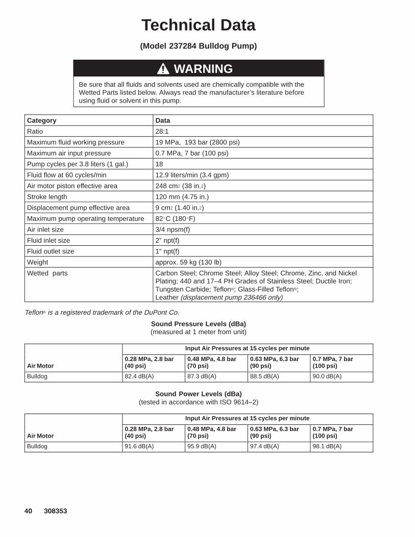
Technical Data(Model 237284 Bulldog Pump)
WARNINGBe sure that all fluids and solvents used are chemically compatible with theWetted Parts listed below. Always read the manufacturer’s literature beforeusing fluid or solvent in this pump.
Category Data
Ratio 28:1
Maximum fluid working pressure 19 MPa, 193 bar (2800 psi)
Maximum air input pressure 0.7 MPa, 7 bar (100 psi)
Pump cycles per 3.8 liters (1 gal.) 18
Fluid flow at 60 cycles/min 12.9 liters/min (3.4 gpm)
Air motor piston effective area 248 cm� (38 in.�)
Stroke length 120 mm (4.75 in.)
Displacement pump effective area 9 cm� (1.40 in.�)
Maximum pump operating temperature 82�C (180�F)
Air inlet size 3/4 npsm(f)
Fluid inlet size 2” npt(f)
Fluid outlet size 1” npt(f)
Weight approx. 59 kg (130 lb)
Wetted parts Carbon Steel; Chrome Steel; Alloy Steel; Chrome, Zinc, and NickelPlating; 440 and 17–4 PH Grades of Stainless Steel; Ductile Iron;Tungsten Carbide; Teflon�; Glass-Filled Teflon�; Leather (displacement pump 236466 only)
Teflon� is a registered trademark of the DuPont Co.
Sound Pressure Levels (dBa)(measured at 1 meter from unit)
Input Air Pressures at 15 cycles per minute
Air Motor0.28 MPa, 2.8 bar (40 psi)
0.48 MPa, 4.8 bar (70 psi)
0.63 MPa, 6.3 bar (90 psi)
0.7 MPa, 7 bar (100 psi)
Bulldog 82.4 dB(A) 87.3 dB(A) 88.5 dB(A) 90.0 dB(A)
Sound Power Levels (dBa)(tested in accordance with ISO 9614–2)
Input Air Pressures at 15 cycles per minute
Air Motor0.28 MPa, 2.8 bar (40 psi)
0.48 MPa, 4.8 bar (70 psi)
0.63 MPa, 6.3 bar (90 psi)
0.7 MPa, 7 bar (100 psi)
Bulldog 91.6 dB(A) 95.9 dB(A) 97.4 dB(A) 98.1 dB(A)

������ ��
Technical Data(Model 237284 Bulldog Pump)
To find Fluid Outlet Pressure (psi/MPa/bar) at a specific fluid flow(lpm/gpm) and operating air pressure (psi/MPa/bar):
1. Locate desired flow along bottom of chart.
2. Follow vertical line up to intersection with selected fluid outletpressure curve (black). Follow left to scale to read fluid outletpressure.
To find Pump Air Consumption (m�/min or scfm) at a specific fluidflow (lpm/gpm) and air pressure (psi/MPa/bar):
1. Locate desired flow along bottom of chart.
2. Read vertical line up to intersection with selected air consumptioncurve (dashes). Follow left to scale to read air consumption.
A 0.7 MPa, 7 bar (100 psi) air pressure B 0.5 MPa, 4.9 bar (70 psi) air pressureC 0.3 MPa, 2.8 bar (40 psi) air pressure
Performance Charts
�
����
����
����
� � � � �
Fluid Outlet Pressure
18 35 50psi
MPa, barcycles per minute
gpmliters/minute 3.8 7.6 11.4
FLU
ID P
RE
SS
UR
E
21, 210
14, 140
A
B
C
�
��
���
���
���
���
� � � � �
Air Consumption
18 35 50scfmm�/min
cycles per minute
gpmliters/minute 3.8 7.6 11.4
AIR
CO
NS
UM
PT
ION
A
B
C
5.60
2.80
Test Fluid: No. 10 Weight Oil
7, 70
15.2
66 66
15.2
1.40
4.20
7.00

�� ������
Technical Data(Model 237292 Reduced Icing Quiet Bulldog Pump)
WARNINGBe sure that all fluids and solvents used are chemically compatible with theWetted Parts listed below. Always read the manufacturer’s literature beforeusing fluid or solvent in this pump.
Category Data
Ratio 28:1
Maximum fluid working pressure 19 MPa, 193 bar (2800 psi)
Maximum air input pressure 0.7 MPa, 7 bar (100 psi)
Pump cycles per 3.8 liters (1 gal.) 18
Fluid flow at 60 cycles/min 12.9 liters/min (3.4 gpm)
Air motor piston effective area 248 cm� (38 in.�)
Stroke length 120 mm (4.75 in.)
Displacement pump effective area 9 cm� (1.40 in.�)
Maximum pump operating temperature 82�C (180�F)
Air inlet size 3/4 npsm(f)
Fluid inlet size 2” npt(f)
Fluid outlet size 1” npt(f)
Weight approx. 59 kg (130 lb)
Wetted parts Carbon Steel; Chrome Steel; Alloy Steel; Chrome, Zinc, and NickelPlating; 440 and 17–4 PH Grades of Stainless Steel; Ductile Iron;Tungsten Carbide; Teflon�; Glass-Filled Teflon�; Leather (displacement pump 236466 only)
Teflon� is a registered trademark of the DuPont Co.
Sound Pressure Levels (dBa)(measured at 1 meter from unit)
Input Air Pressures at 15 cycles per minute
Air Motor0.28 MPa, 2.8 bar (40 psi)
0.48 MPa, 4.8 bar (70 psi)
0.63 MPa, 6.3 bar (90 psi)
0.7 MPa, 7 bar (100 psi)
Reduced Icing Quiet Bulldog 81.5 dB(A) 83.6 dB(A) 85.6 dB(A) 85.8 dB(A)
Sound Power Levels (dBa)(tested in accordance with ISO 9614–2)
Input Air Pressures at 15 cycles per minute
Air Motor0.28 MPa, 2.8 bar (40 psi)
0.48 MPa, 4.8 bar (70 psi)
0.63 MPa, 6.3 bar (90 psi)
0.7 MPa, 7 bar (100 psi)
Reduced Icing Quiet Bulldog 90.2 dB(A) 93.5 dB(A) 94.9 dB(A) 93.3 dB(A)

������ ��
Technical Data(Model 237292 Reduced Icing Quiet Bulldog Pump)
To find Fluid Outlet Pressure (psi/MPa/bar) at a specific fluid flow(lpm/gpm) and operating air pressure (psi/MPa/bar):
1. Locate desired flow along bottom of chart.
2. Follow vertical line up to intersection with selected fluid outletpressure curve (black). Follow left to scale to read fluid outletpressure.
To find Pump Air Consumption (m�/min or scfm) at a specific fluidflow (lpm/gpm) and air pressure (psi/MPa/bar):
1. Locate desired flow along bottom of chart.
2. Read vertical line up to intersection with selected air consumptioncurve (dashes). Follow left to scale to read air consumption.
A 0.7 MPa, 7 bar (100 psi) air pressure B 0.5 MPa, 4.9 bar (70 psi) air pressureC 0.3 MPa, 2.8 bar (40 psi) air pressure
Performance Charts
�
����
����
����
� � � � �
Fluid Outlet Pressure
18 36 54psi
MPa, barcycles per minute
gpmliters/minute 3.8 7.6 11.4
FLU
ID P
RE
SS
UR
E
21, 210
14, 140
A
B
C
�
��
���
���
���
� � � � �
Air Consumption
18 36 54scfmm�/min
cycles per minute
gpmliters/minute 3.8 7.6 11.4
AIR
CO
NS
UM
PT
ION
A
BC
5.60
2.80
Test Fluid: No. 10 Weight Oil
7, 70
15.2
71 71
15.2
1.40
4.20

�� ������
Technical Data(Model 237279 Senator Pump)
WARNINGBe sure that all fluids and solvents used are chemically compatible with theWetted Parts listed below. Always read the manufacturer’s literature beforeusing fluid or solvent in this pump.
Category Data
Ratio 17:1
Maximum fluid working pressure 11 MPa, 117 bar (1700 psi)
Maximum air input pressure 0.7 MPa, 7 bar (100 psi)
Pump cycles per 3.8 liters (1 gal.) 18
Fluid flow at 60 cycles/min 12.9 liters/min (3.4 gpm)
Air motor piston effective area 154 cm� (24 in.�)
Stroke length 120 mm (4.75 in.)
Displacement pump effective area 9 cm� (1.40 in.�)
Maximum pump operating temperature 82�C (180�F)
Air inlet size 3/4 npsm(f)
Fluid inlet size 2” npt(f)
Fluid outlet size 1” npt(f)
Weight approx. 43 kg (95 lb)
Wetted parts Carbon Steel; Chrome Steel; Alloy Steel; Chrome, Zinc, and NickelPlating; 440 and 17–4 PH Grades of Stainless Steel; Ductile Iron;Tungsten Carbide; Teflon�; Glass-Filled Teflon�; Leather (displacement pump 236466 only)
Teflon� is a registered trademark of the DuPont Co.
Sound Pressure Levels(tested at 1 meter from motor)
Input Air Pressures at 15 cycles per minute
Air Motor40 psi (2.8 bar, 280 kPa)
70 psi (4.8 bar, 480 kPa)
90 psi (6 bar, 600 kPa)
100 psi (7 bar, 700 kPa)
Standard Senator 84.3 dB(A) 87.8 dB(A) 89.8 dB(A) 91.2 dB(A)
Sound Power Levels(tested in accordance with ISO 9614)
Input Air Pressures at 15 cycles per minute
Air Motor40 psi (2.8 bar, 280 kPa)
70 psi (4.8 bar, 480 kPa)
90 psi (6 bar, 600 kPa)
100 psi (7 bar, 700 kPa)
Standard Senator 91.6 dB(A) 94.6 dB(A) 96.4 dB(A) 97.3 dB(A)

������ ��
Technical Data(Model 237279 Senator Pump)
To find Fluid Outlet Pressure (psi/MPa/bar) at a specific fluid flow(lpm/gpm) and operating air pressure (psi/MPa/bar):
1. Locate desired flow along bottom of chart.
2. Follow vertical line up to intersection with selected fluid outletpressure curve (black). Follow left to scale to read fluid outletpressure.
To find Pump Air Consumption (m�/min or scfm) at a specific fluidflow (lpm/gpm) and air pressure (psi/MPa/bar):
1. Locate desired flow along bottom of chart.
2. Read vertical line up to intersection with selected air consumptioncurve (dashes). Follow left to scale to read air consumption.
A 0.7 MPa, 7 bar (100 psi) air pressure B 0.5 MPa, 4.9 bar (70 psi) air pressureC 0.3 MPa, 2.8 bar (40 psi) air pressure
Performance Charts
�
���
����
����
����
� � � � �
Fluid Outlet Pressure
17 34 52psi
MPa, barcycles per minute
gpmliters/minute 3.8 7.6 11.4
FLU
ID P
RE
SS
UR
E
14, 140
A
B
C
�
��
��
��
���
� � � � �
Air Consumption
17 34 52scfmm�/min
cycles per minute
gpmliters/minute 3.8 7.6 11.4
AIR
CO
NS
UM
PT
ION
A
B
C
2.80
Test Fluid: No. 10 Weight Oil
7, 70
15.2
69 69
15.2
1.40
10, 105
3.5, 35 0.70
2.10

�� ������
Technical Data(Model 237290 Viscount Pump)
WARNINGBe sure that all fluids and solvents used are chemically compatible with theWetted Parts listed below. Always read the manufacturer’s literature beforeusing fluid or solvent in this pump.
Category Data
Ratio 3.5:1
Maximum fluid working pressure 34 MPa, 345 bar (5000 psi)
Maximum hydraulic oil input pressure 9.9 MPa, 99 bar (1428 psi)
Pump cycles per 3.8 liters (1 gal.) 18
Fluid flow at 60 cycles/min 12.9 liters/min (3.4 gpm)
Hydraulic motor piston effective area 31.6 cm� (4.9 in.�)
Stroke length 120 mm (4.75 in.)
Displacement pump effective area 9 cm� (1.40 in.�)
Maximum pump operating temperature 82�C (180�F)
* Noise level at 1450 psi hydraulicpressure, 25 cycles/min
88 dB(A)
* Sound power level at 1450 psihydraulic pressure, 25 cycles/min
103 dB(A)
Hydraulic oil inlet size 3/4 npt(f)
Fluid inlet size 2” npt(f)
Fluid outlet size 1” npt(f)
Weight approx. 68 kg (150 lb)
Wetted parts Carbon Steel; Chrome Steel; Alloy Steel; Chrome, Zinc, and NickelPlating; 440 and 17–4 PH Grades of Stainless Steel; Ductile Iron;Tungsten Carbide; Teflon�; Glass-Filled Teflon�; Leather (displacement pump 236466 only)
* Tested in accordance with ISO 3744. Teflon� is a registered trademark of the DuPont Co.

������ ��
Technical Data(Model 237290 Viscount Pump)
To find Fluid Outlet Pressure (psi/MPa/bar) at a specific fluid flow(lpm/gpm) and operating hydraulic pressure (psi/MPa/bar):
1. Locate desired flow along bottom of chart.
2. Follow vertical line up to intersection with selected fluid outletpressure curve (black). Follow left to scale to read fluid outletpressure.
To find Pump Hydraulic Oil Consumption (gpm or lpm) at a specificfluid flow (lpm/gpm):
1. Locate desired flow along bottom of chart.
2. Read vertical line up to intersection with selected hydraulic con-sumption curve (dashes). Follow left to scale to read oil consump-tion.
A 9.9 MPa, 99 bar (1428 psi) hydraulic oil pressure B 7 MPa, 70 bar (1000 psi) hydraulic pressureC 4 MPa, 40 bar (571 psi) hydraulic pressure
Performance Charts
�
����
����
����
����
����
� � � � �
Fluid Outlet Pressure
18 36 54psi
MPa, barcycles per minute
gpmliters/minute 3.8 7.6 11.4
FLU
ID P
RE
SS
UR
E
34, 345
28, 280
14, 140
A
B
C
�
�
�
�
�
��
� � � � �
Hydraulic Oil Consumption
18 36 54
gpmlpm
(hyd. oil)cycles per minute
gpmliters/minute 3.8 7.6 11.4
OIL
CO
NS
UM
PT
ION 38.0
22.8
Test Fluid: No. 10 Weight Oil
21, 210
7, 70
15.2
72 72
15.2
15.2
30.4
hydraulic oilconsumption
���

�� ������
Technical Data(Model 917028 Viscount II Pump)
WARNINGBe sure that all fluids and solvents used are chemically compatible with theWetted Parts listed below. Always read the manufacturer’s literature beforeusing fluid or solvent in this pump.
Category Data
Ratio 3.5:1
Maximum fluid working pressure 34 MPa, 345 bar (5000 psi)
Maximum hydraulic oil input pressure 9.9 MPa, 99 bar (1428 psi)
Pump cycles per 3.8 liters (1 gal.) 18
Fluid flow at 60 cycles/min 12.9 liters/min (3.4 gpm)
Hydraulic motor piston effective area 31.6 cm� (4.9 in.�)
Stroke length 120 mm (4.75 in.)
Displacement pump effective area 9 cm� (1.40 in.�)
Maximum pump operating temperature 82�C (180�F)
* Noise level at 1450 psi hydraulicpressure, 25 cycles/min
88 dB(A)
* Sound power level at 1450 psihydraulic pressure, 25 cycles/min
103 dB(A)
Hydraulic oil inlet size 3/4 npt(f)
Fluid inlet size 2” npt(f)
Fluid outlet size 1” npt(f)
Weight approx. 68 kg (150 lb)
Wetted parts Carbon Steel; Chrome Steel; Alloy Steel; Chrome, Zinc, and NickelPlating; 440 and 17–4 PH Grades of Stainless Steel; Ductile Iron;Tungsten Carbide; Teflon�; Glass-Filled Teflon�; Ultra-High MolecularWeight Polyethylene (displacement pump 240682 only)
* Tested in accordance with ISO 3744. Teflon� is a registered trademark of the DuPont Co.

������ ��
Technical Data(Model 917028 Viscount II Pump)
To find Fluid Outlet Pressure (psi/MPa/bar) at a specific fluid flow(lpm/gpm) and operating hydraulic pressure (psi/MPa/bar):
1. Locate desired flow along bottom of chart.
2. Follow vertical line up to intersection with selected fluid outletpressure curve (black). Follow left to scale to read fluid outletpressure.
To find Pump Hydraulic Oil Consumption (gpm or lpm) at a specificfluid flow (lpm/gpm):
1. Locate desired flow along bottom of chart.
2. Read vertical line up to intersection with selected hydraulic con-sumption curve (dashes). Follow left to scale to read oil consump-tion.
A 9.9 MPa, 99 bar (1428 psi) hydraulic oil pressure B 7 MPa, 70 bar (1000 psi) hydraulic pressureC 4 MPa, 40 bar (571 psi) hydraulic pressure
Performance Charts
�
����
����
����
����
����
� � � � �
Fluid Outlet Pressure
18 36 54psi
MPa, barcycles per minute
gpmliters/minute 3.8 7.6 11.4
FLU
ID P
RE
SS
UR
E
34, 345
28, 280
14, 140
A
B
C
�
�
�
�
�
��
� � � � �
Hydraulic Oil Consumption
18 36 54
gpmlpm
(hyd. oil)cycles per minute
gpmliters/minute 3.8 7.6 11.4
OIL
CO
NS
UM
PT
ION 38.0
22.8
Test Fluid: No. 10 Weight Oil
21, 210
7, 70
15.2
72 72
15.2
15.2
30.4
hydraulic oilconsumption
���

�� ������
Dimensions
Pump Dimensions
������
A
B
C
D
E
F
G
Mounting Hole Layout
101.6 mm(4.0”)
50.8 mm(2.0”)
88 mm(3.464”)
94.28 mm(3.712”)
11.1 mm(0.437”)DIA (4)
94.28 mm(3.712”)
0653
Three M16 x 2.0Holes
Pump Model A B C D E F G
236475240946
1146.9 mm(45.15 in.)
746.0 mm(29.37 in.)
400.9 mm(15.78 in.)
413.0 mm(16.26 in.)
2 in. npt(f) 1 in. npt(f) 3/4 npsm(f)
237278 1180 mm(46.44 in.)
590 mm(23.23 in.)
590 mm(23.21 in.)
257 mm(10.12 in.)
2 in. npt(f) 1 in. npt(f) 3/4 npsm(f)
237283 1329 mm(52.32 in.)
746.0 mm(29.37 in.)
583 mm(22.95 in.)
457 mm(17.99 in)
2 in. npt(f) 1 in. npt(f) 3/4 npsm(f)
237284 1134 mm(44.65 in.)
590 mm(23.23 in.)
544 mm(21.42 in.)
257 mm(10.12 in.)
2 in. npt(f) 1 in. npt(f) 3/4 npsm(f)
237292 1180 mm(46.44 in.)
590 mm(23.23 in.)
590 mm(23.23 in.)
301 mm(11.85 in.)
2 in. npt(f) 1 in. npt(f) 3/4 npsm(f)
237279 1138 mm(44.80 in.)
590 mm(23.23 in.)
548 mm(21.57 in.)
257 mm(10.12 in.)
2 in. npt(f) 1 in. npt(f) 3/4 npsm(f)
237290917028
1344 mm(52.91 in.)
681 mm(26.81 in.)
663 mm(26.10 in.)
not applicable 2 in. npt(f) 1 in. npt(f) 3/4 npt(f)

������ ��
Manual Change SummaryPart number 240946 Pump has been added to the manual.
Flats have been added to the pump cylinder.
Displacement pump torque values have changed.
Changes have been made to the Technical Data.
The Performance Charts have been reformatted.

�� ������
Graco Standard WarrantyGraco warrants all equipment manufactured by Graco and bearing its name to be free from defects in material and workmanship on thedate of sale by an authorized Graco distributor to the original purchaser for use. With the exception of any special, extended, or limitedwarranty published by Graco, Graco will, for a period of twelve months from the date of sale, repair or replace any part of the equipmentdetermined by Graco to be defective. This warranty applies only when the equipment is installed, operated and maintained in accor-dance with Graco’s written recommendations.
This warranty does not cover, and Graco shall not be liable for general wear and tear, or any malfunction, damage or wear caused byfaulty installation, misapplication, abrasion, corrosion, inadequate or improper maintenance, negligence, accident, tampering, or sub-stitution of non–Graco component parts. Nor shall Graco be liable for malfunction, damage or wear caused by the incompatibility ofGraco equipment with structures, accessories, equipment or materials not supplied by Graco, or the improper design, manufacture,installation, operation or maintenance of structures, accessories, equipment or materials not supplied by Graco.
This warranty is conditioned upon the prepaid return of the equipment claimed to be defective to an authorized Graco distributor forverification of the claimed defect. If the claimed defect is verified, Graco will repair or replace free of charge any defective parts. Theequipment will be returned to the original purchaser transportation prepaid. If inspection of the equipment does not disclose any defectin material or workmanship, repairs will be made at a reasonable charge, which charges may include the costs of parts, labor, andtransportation.
THIS WARRANTY IS EXCLUSIVE, AND IS IN LIEU OF ANY OTHER WARRANTIES, EXPRESS OR IMPLIED, INCLUDING BUTNOT LIMITED TO WARRANTY OF MERCHANTABILITY OR WARRANTY OF FITNESS FOR A PARTICULAR PURPOSE.
Graco’s sole obligation and buyer’s sole remedy for any breach of warranty shall be as set forth above. The buyer agrees that no otherremedy (including, but not limited to, incidental or consequential damages for lost profits, lost sales, injury to person or property, or anyother incidental or consequential loss) shall be available. Any action for breach of warranty must be brought within two (2) years of thedate of sale.
Graco makes no warranty, and disclaims all implied warranties of merchantability and fitness for a particular purpose in connectionwith accessories, equipment, materials or components sold but not manufactured by Graco. These items sold, but not manufacturedby Graco (such as electric motors, switches, hose, etc.), are subject to the warranty, if any, of their manufacturer. Graco will providepurchaser with reasonable assistance in making any claim for breach of these warranties.
In no event will Graco be liable for indirect, incidental, special or consequential damages resulting from Graco supplying equipmenthereunder, or the furnishing, performance, or use of any products or other goods sold hereto, whether due to a breach of contract,breach of warranty, the negligence of Graco, or otherwise.
FOR GRACO CANADA CUSTOMERSThe parties acknowledge that they have required that the present document, as well as all documents, notices and legal proceedingsentered into, given or instituted pursuant hereto or relating directly or indirectly hereto, be drawn up in English. Les parties reconnais-sent avoir convenu que la rédaction du présente document sera en Anglais, ainsi que tous documents, avis et procédures judiciairesexécutés, donnés ou intentés à la suite de ou en rapport, directement ou indirectement, avec les procedures concernées.
Graco Phone NumberTO PLACE AN ORDER , contact your Graco distributor, or call this number to identify the distributor closest to you:1–800–367–4023 Toll Free
All written and visual data contained in this document reflects the latest product information available at the time of publication.Graco reserves the right to make changes at any time without notice.
Sales Offices: Minneapolis, DetroitForeign Offices: Belgium, Korea, Hong Kong, Japan
GRACO INC. P.O. BOX 1441 MINNEAPOLIS, MN 55440–1441www.graco.com
PRINTED IN U.S.A. 308353 August 1994, Revised May 1999