carbon steel handbook
DESCRIPTION
TRANSCRIPT
Carbon Steel Handbook
Effective December 6, 2006, this report has been made publicly available in accordance with Section 734.3(b)(3) and published in accordance with Section 734.7 of the U.S. Export Administration Regulations. As a result of this publication, this report is subject to only copyright protection and does not require any license agreement from EPRI. This notice supersedes the export control restrictions and any proprietary licensed material notices embedded in the document prior to publication.

EPRI Project Manager D. Gandy
ELECTRIC POWER RESEARCH INSTITUTE 3420 Hillview Avenue, Palo Alto, California 94304-1338 PO Box 10412, Palo Alto, California 94303-0813 USA
800.313.3774 650.855.2121 [email protected] www.epri.com
Carbon Steel Handbook 1014670
Final Report, March 2007
DISCLAIMER OF WARRANTIES AND LIMITATION OF LIABILITIES
THIS DOCUMENT WAS PREPARED BY THE ORGANIZATION(S) NAMED BELOW AS AN ACCOUNT OF WORK SPONSORED OR COSPONSORED BY THE ELECTRIC POWER RESEARCH INSTITUTE, INC. (EPRI). NEITHER EPRI, ANY MEMBER OF EPRI, ANY COSPONSOR, THE ORGANIZATION(S) BELOW, NOR ANY PERSON ACTING ON BEHALF OF ANY OF THEM:
(A) MAKES ANY WARRANTY OR REPRESENTATION WHATSOEVER, EXPRESS OR IMPLIED, (I) WITH RESPECT TO THE USE OF ANY INFORMATION, APPARATUS, METHOD, PROCESS, OR SIMILAR ITEM DISCLOSED IN THIS DOCUMENT, INCLUDING MERCHANTABILITY AND FITNESS FOR A PARTICULAR PURPOSE, OR (II) THAT SUCH USE DOES NOT INFRINGE ON OR INTERFERE WITH PRIVATELY OWNED RIGHTS, INCLUDING ANY PARTY'S INTELLECTUAL PROPERTY, OR (III) THAT THIS DOCUMENT IS SUITABLE TO ANY PARTICULAR USER'S CIRCUMSTANCE; OR
(B) ASSUMES RESPONSIBILITY FOR ANY DAMAGES OR OTHER LIABILITY WHATSOEVER (INCLUDING ANY CONSEQUENTIAL DAMAGES, EVEN IF EPRI OR ANY EPRI REPRESENTATIVE HAS BEEN ADVISED OF THE POSSIBILITY OF SUCH DAMAGES) RESULTING FROM YOUR SELECTION OR USE OF THIS DOCUMENT OR ANY INFORMATION, APPARATUS, METHOD, PROCESS, OR SIMILAR ITEM DISCLOSED IN THIS DOCUMENT.
ORGANIZATION(S) THAT PREPARED THIS DOCUMENT
Flenner Engineering Services, LLC
NOTE
For further information about EPRI, call the EPRI Customer Assistance Center at 800.313.3774 or e-mail [email protected].
Electric Power Research Institute, EPRI, and TOGETHER…SHAPING THE FUTURE OF ELECTRICITY are registered service marks of the Electric Power Research Institute, Inc.
Copyright © 2007 Electric Power Research Institute, Inc. All rights reserved.
iii
CITATIONS
This report was prepared by
Flenner Engineering Services, LLC 6537 Wyndham Dr. Kalamazoo, MI 49009
Principal Investigator P. Flenner
This report describes research sponsored by the Electric Power Research Institute (EPRI).
The report is a corporate document that should be cited in the literature in the following manner:
Carbon Steel Handbook. EPRI, Palo Alto, CA: 2007. 1014670.

v
PRODUCT DESCRIPTION
This report, one in an ongoing series of metallurgical reports, is devoted to iron-based alloys that contain only residual amounts of elements other than the primary alloying element, carbon—the definition of carbon steel. Because of its attractive cost, wide availability, and ease of fabrication and weldability, carbon steel is one of the most commonly used materials in the electric power generation industry. Carbon steels in which carbon represents 0.15–0.35%—those used most often as boiler and piping materials—are the focus of this Carbon Steel Handbook.
Although carbon steel is available in virtually all product forms, it is the pressure-containing applications that are of primary interest in this report: pipes, tubes, plates, castings, forgings, and wrought fittings.
Results and Findings The report presents technical background information on carbon steels and the various international standards that apply to them; applicable American Society of Mechanical Engineers (ASME) and ASTM International (ASTM) codes; the metallurgy of carbon steels; the physical, mechanical, creep, graphitization, fatigue, and grain growth properties of carbon steels; oxidation resistance; and fabrication and welding issues. Two appendices—one containing a table of material chemical compositions and the other containing a table of mechanical properties of selected carbon steels—are included.
Challenges and Objectives Maintaining an accurate knowledge of the full range of boiler materials has become increasingly challenging: even for well-established alloys, the information base continues to expand, and new alloys with complex metallurgies are regularly introduced. The intent of this report and the others in the series is to provide a comprehensive materials reference that organizes relevant information in a concise manner for each material.
vi
Applications, Value, and Use The report will serve as a reference for utility engineers who must make decisions about projects that involve carbon steels. An underlying assumption is that engineers and other plant personnel will benefit from access to information about relevant codes and standards, the metallurgical characteristics of carbon steels, and their mechanical properties. Because carbon is a particularly powerful alloying element in steel, there are significant differences in the strength, hardness, and ductility achievable with relatively small variations in the proportion of carbon.
Although this report concentrates primarily on the pressure-containing applications of carbon steels, it will also be a useful tool in addressing structural fabrication issues. To give it the convenient portability of a field guide, this report has been formatted as a pocket handbook.
EPRI Perspective This report and the others in the series provide information about the most common boiler materials. Although each has been produced as a volume on an individual alloy, a broader perspective of the metallurgical aspects of boiler steels can be gained through the EPRI report Metallurgical Guidebook for Fossil Power Plant Boilers (1011912). Readers might also wish to consult the previous EPRI reports in this series—The Grade 22 Low Alloy Steel Handbook (1011534) and The Grades 11 and 12 Low Alloy Steel Handbook (1013358).
Approach This series is being developed for several major component materials used in fossil power production. In each section of these reports, the project team has presented information in a succinct manner, with references to source documents supporting technical information.
Keywords Carbon steel Fabrication issues Metallurgy Standards and codes Welding issues
vii
CONTENTS
1 INTRODUCTION...................................................................................1-1
2 TECHNICAL BACKGROUND...............................................................2-1 2.1 Forms Available ......................................................................................... 2-7 2.2 Applications ................................................................................................ 2-8
3 STANDARDS AND CODES..................................................................3-1 3.1 Specifications ............................................................................................. 3-1 3.2 ASME Codes.............................................................................................. 3-6
3.2.1 Allowable Stresses .................................................................... 3-7
3.2.2 P Number Identification ............................................................. 3-9
4 METALLURGY .....................................................................................4-1 4.1 Chemical Composition ............................................................................... 4-1 4.2 Carbon Equivalence................................................................................... 4-3 4.3 Microstructure and Heat Treatment ........................................................... 4-4
4.3.1 Microstructure ............................................................................ 4-4
4.3.2 Transformation Behavior ........................................................... 4-9
4.3.3 Transformation Diagrams ........................................................ 4-19
4.3.4 Heat Treatment........................................................................ 4-24
5 PROPERTIES.......................................................................................5-1 5.1 Physical Properties .................................................................................... 5-1 5.2 Mechanical Properties ............................................................................... 5-6 5.3 Creep Properties ........................................................................................ 5-7 5.4 Graphitization ........................................................................................... 5-11 5.5 Fatigue Properties.................................................................................... 5-14 5.6 Grain Growth Effect on Properties........................................................... 5-15
6 OXIDATION RESISTANCE...................................................................6-1 6.1 Scale Formation ......................................................................................... 6-1 6.2 Life Assessment by Oxide Thickness Measurement................................. 6-2
viii
7 FABRICATION .....................................................................................7-1 7.1 Machinability .............................................................................................. 7-1 7.2 Forming and Forging.................................................................................. 7-1 7.3 Welding ...................................................................................................... 7-2
7.3.1 Weldability ................................................................................. 7-2
7.3.2 Weld Joint Preparation .............................................................. 7-5
7.3.3 WPSs....................................................................................... 7-10
7.3.4 Welder and Welding Operator Qualification............................ 7-12
7.3.5 Preheat and PWHT ................................................................. 7-12
7.3.6 Filler Metal Selection ............................................................... 7-17 7.4 Repair....................................................................................................... 7-18 7.5 Welding Dissimilar Steels ........................................................................ 7-19
8 REFERENCES......................................................................................8-1
A MATERIAL CHEMICAL COMPOSITIONS .......................................... A-1
B MECHANICAL PROPERTIES OF SELECTED CARBON STEELS.................................................................................................. B-1
ix
LIST OF FIGURES
Figure 3-1 Allowable Stress Trend Curves, SA-516 Gr. 65 ......................................... 3-8 Figure 4-1 Carbon Steel Microstructures ..................................................................... 4-6 Figure 4-2 The Growth of Bainite and the Development of Upper and Lower
Bainite Morphologies........................................................................................ 4-8 Figure 4-3 Iron-Iron Carbide Phase Diagram ............................................................. 4-10 Figure 4-4 Schematic Representation of Plain Carbon Steel (0.20%
Carbon) When Heated Rapidly to the Temperature Shown .......................... 4-12 Figure 4-5 Schematic Representation of Transformations of Carbon Steel
with Slow Cooling ........................................................................................... 4-14 Figure 4-6 Microstructure of Upper Bainite as Seen in the Transmission
Electron Microscope....................................................................................... 4-16 Figure 4-7 Microstructure of Lower Bainite as Seen in the Transmission
Electron Microscope....................................................................................... 4-17 Figure 4-8 Microstructure of Water-Quenched Low-Alloy Steel Showing
Lath Martensite............................................................................................... 4-18 Figure 4-9 The Relationship Between Carbon Content and Maximum
Obtainable Hardness in Carbon or Alloy Steels ............................................ 4-19 Figure 4-10 The Relationship of CCT and IT Diagrams for Eutectoid Steel .............. 4-20 Figure 4-11 Isothermal Transformation Diagram for SAE 1021 Steel (0.20%
Carbon)........................................................................................................... 4-22 Figure 4-12 Isothermal Transformation Diagram for AISI-SAE 1035 Steel ............... 4-23 Figure 5-1 Carbon Steel (AISI 1025) Specific Heat Versus Temperature ................... 5-5 Figure 5-2 Design Tensile and Yield Strength of Carbon Steels Versus
Temperature ..................................................................................................... 5-6 Figure 5-3 Elevated Temperature Material Properties, Including Creep
Rupture for Medium Carbon Steel ................................................................... 5-8 Figure 5-4 Variation of the LMP with Stress for Rupture of Carbon Steel
Pipe and Tube .................................................................................................. 5-9 Figure 5-5 Variation of LMP with Stress for Rupture of Carbon Steel Plate .............. 5-10 Figure 5-6 The Relationship Between Graphitization, Temperature, and
Time................................................................................................................ 5-12 Figure 5-7 Photomicrograph Illustrating Graphitization (the Black Nodules)
in a Weld Heat-Affected Zone ........................................................................ 5-12 Figure 5-8 Typical S-N Curve for Medium Strength Carbon Steel ............................. 5-14 Figure 5-9 The Effect of Steel Microstructure on the Endurance Ratio ..................... 5-15
x
Figure 5-10 The Effect of Grain Size on Transition Temperature .............................. 5-16 Figure 5-11 The Relationship Between 105-Hour Creep Rupture Strength
and Ultimate Tensile Strength for Carbon Steel ............................................ 5-17 Figure 7-1 Typical Butt Weld Joint Preparations .......................................................... 7-7 Figure 7-2 A Typical Weld Joint Preparation Trimmed for Misalignment..................... 7-8 Figure 7-3 A Typical Welding End Transition: Maximum Envelope ............................. 7-9
xi
LIST OF TABLES
Table 2-1 Comparative International Specifications..................................................... 2-2 Table 3-1 Specific Carbon Steel ASME/ASTM Material Specifications
Covered and Source/Edition Information ......................................................... 3-2 Table 3-2 The Specific Carbon Steel International Material Specifications
Covered ............................................................................................................ 3-5 Table 5-1 Typical Physical Properties of Carbon Steel................................................ 5-2 Table 5-2 The Variation in Selected Physical Properties with Temperature................ 5-3 Table 5-3 Carbon Steel (AISI 1025) Specific Heat (Joules/Kilogram -
°Kelvin) Data Versus Temperature .................................................................. 5-5 Table 6-1 Maximum Metal Temperatures .................................................................... 6-1 Table 7-1 Listed Materials Without Current ASME Section IX P Number
Designations or with Group Number Exceptions ............................................. 7-3 Table A-1 Material Chemical Compositions .................................................................A-2 Table B-1 Mechanical Properties of Selected Carbon Steels ......................................B-2

1-1
1 INTRODUCTION
It is important to clarify the meaning of carbon steel in the generic sense and in the more narrow context used in this report. The term steel is usually taken to mean an iron-based alloy containing carbon in amounts less than about 2%. Carbon steels (sometimes also termed plain carbon steels, ordinary steels, or straight carbon steels) can be defined as steels that contain only residual amounts of elements other than carbon, except those (such as silicon and aluminum) added for deoxidation and those (such as manganese and cerium) added to counteract certain deleterious effects of residual sulfur. However, silicon and manganese can be added in amounts greater than those required strictly to meet these criteria so that arbitrary upper limits for these elements have to be set; usually, 0.60% for silicon and 1.65% for manganese are accepted as the limits for carbon steel.
The carbon steels of interest in this report are those with carbon equal to or less than about 0.35% to facilitate welding. A further distinction can be made according to carbon content. Low-carbon steels (below 0.15% carbon) contain too little carbon to benefit from hardening and are frequently used in the hot-worked or—for maximum ductility—the annealed condition. Steels of less than 0.25% carbon (often referred to as mild steel) have somewhat higher strength near the upper carbon level. Medium-carbon steels (0.25–0.55% carbon) are often heat-treated (quenched and tempered) to achieve yet higher strength, but it is mainly the compositions below 0.35% carbon that are relevant to this report.
Carbon steel is one of the most widely used materials in the industry. This material is used not only in many of the water- and steam-pressure-containing systems in power plants but also in the supports for these systems. Although this report concentrates primarily on the pressure-containing applications of carbon steels, it can also be a useful tool for structural carbon steel fabrication issues.
As the description implies, the primary alloying element of these iron-based materials is carbon. Because carbon is such a powerful alloying element in steel, there are significant differences in the strength, hardness, and ductility achievable with relatively small variations in the levels of carbon in the composition. However, other important factors—such as material fabrication, heat treatment, component fabrication, and

Introduction
1-2
fabrication processes—can result in significant changes to the properties of the carbon steel components.
In some cases, requirements established by codes and standards must be supplemented to achieve adequate results when working with carbon steels. It is important for the utility engineer to have access to metallurgical and properties information to aid in making decisions for projects involving carbon steels. This report is intended to provide such information on the most common boiler and piping materials used in power plants. Not all carbon steels will be covered explicitly, but the user should be able to draw relevant information needed for any required decision.
2-1
2 TECHNICAL BACKGROUND
The carbon steel materials used in pressure applications cover a very wide range of mechanical properties. Carbon steel materials are listed in the American Society of Mechanical Engineers (ASME) Boiler and Pressure Vessel (B&PV) Code [1] with a room temperature tensile strength range from 40 kips per square inch (ksi) (275 megapascals [MPa]) up to 100 ksi (690 MPa). Most of the higher strength materials have very limited application in power plants; accordingly, the materials covered in this report will be limited to those with a specified minimum tensile strength less than 80 ksi (550 MPa).
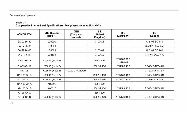
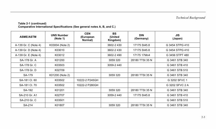
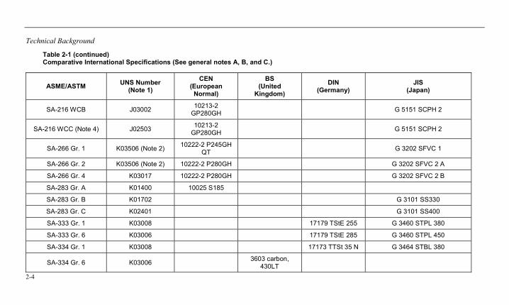
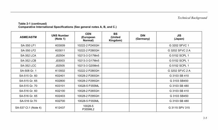
Carbon steels are used in the United States and throughout the world for nearly all of the same reasons: their cost, properties, ease of fabrication, availability, weldability, and so on. Table 2-1 lists some ASME material specifications covered in this report with some comparative European material specifications and with those of the UK, Germany, and Japan (where comparative international specifications are identified) [2]. However, it is important to note that these materials are not necessarily exactly equivalent because there can be minor differences in the chemical composition or mechanical properties requirements for the material. Note that in Table 2-1, these are designated as comparative materials, not equivalent materials. The material specifications of ASME and ASTM International (ASTM), which are listed as comparative, are similar in both chemistry and mechanical properties to those of the international specifications listed. In general, an alloy is considered comparable if the specified mechanical properties are essentially the same despite variation in the compositions. The specifications are not identical, so they cannot be considered equivalent. It is possible that a material meets the requirements of any or all of the comparative specifications. Where available, the Unified Numbering System (UNS) [3] identification is also given because this identification provides some link between materials with the same chemical composition (and to some extent, with their mechanical properties) and has some significance in the ASME Codes.
Technical Background
2-2
Table 2-1 Comparative International Specifications (See general notes A, B, and C.)
ASME/ASTM UNS Number (Note 1)
CEN (European
Normal)
BS (United
Kingdom) DIN
(Germany) JIS
(Japan)
SA-27 60-30 J03000 3100 A1 G 5101 SC 410
SA-27 65-35 J03001 G 5102 SCW 450
SA-27 70-36 J03501 3100 A2 G 5101 SC 480
A-27 70-40 J02501 3100 A2 G 5101 SCW 480
SA-53 Gr. A K02504 (Note 2) 3601 320 17175 St35.8 (Note 3)
SA-53 Gr. B K03005 (Note 2) 3602-2 430 17175 St45.8 G 3454 STPG 410
SA-105 K03504 (Note 2) 10222-2 P 280GH G 3202 SFVC 2 A
SA-106 Gr. B K03006 (Note 2) 3602-2 430 17175 St45.8 G 3454 STPG 410
SA-106 Gr. C K03501 (Note 2) 3602-2 490 17175 17Mn4 G 3456 STPT 480
SA-135 Gr. A K02509 3601 320
SA-135 Gr. B K03018 3602-2 430 17175 St45.8 G 3454 STPG 410
A-139 Gr. A -- 3601 320
A-139 Gr. B K03003 (Note 2) 3602-2 430 17175 St45.8 G 3454 STPG 410
Technical Background
2-3
Table 2-1 (continued) Comparative International Specifications (See general notes A, B, and C.)
ASME/ASTM UNS Number (Note 1)
CEN (European
Normal)
BS (United
Kingdom) DIN
(Germany) JIS
(Japan)
A-139 Gr. C (Note 4) K03004 (Note 2) 3602-2 430 17175 St45.8 G 3454 STPG 410
A-139 Gr. D (Note 4) K03010 3602-2 430 17175 St45.8 G 3454 STPG 410
A-139 Gr. E (Note 4) K03012 3602-2 490 17175 17Mn4 G 3456 STPT 480
SA-178 Gr. A K01200 3059 320 28180 TTSt 35 N G 3461 STB 340
SA-178 Gr. C K03503 3059-2 440 G 3461 STB 410
SA-178 Gr. D K02709 G 3461 STB 510
SA-179 K01200 (Note 2) 3059 320 28180 TTSt 35 N G 3461 STB 340
SA-181 Cl. 60 K03502 10222-2 P245GH G 3202 SFVC 1
SA-181 Cl. 70 K03502 10222-2 P280GH G 3202 SFVC 2 A
SA-192 K01201 3059 320 28180 TTSt 35 N G 3461 STB 340
SA-210 Gr. A1 K02707 3059-2 440 17175 St45.8 G 3461 STB 410
SA-210 Gr. C K03501 G 3461 STB 510
SA-214 K01807 3059 320 28180 TTSt 35 N G 3461 STB 340
Technical Background
2-4
Table 2-1 (continued) Comparative International Specifications (See general notes A, B, and C.)
ASME/ASTM UNS Number (Note 1)
CEN (European
Normal)
BS (United
Kingdom) DIN
(Germany) JIS
(Japan)
SA-216 WCB J03002 10213-2 GP280GH G 5151 SCPH 2
SA-216 WCC (Note 4) J02503 10213-2 GP280GH G 5151 SCPH 2
SA-266 Gr. 1 K03506 (Note 2) 10222-2 P245GH QT G 3202 SFVC 1
SA-266 Gr. 2 K03506 (Note 2) 10222-2 P280GH G 3202 SFVC 2 A
SA-266 Gr. 4 K03017 10222-2 P280GH G 3202 SFVC 2 B
SA-283 Gr. A K01400 10025 S185
SA-283 Gr. B K01702 G 3101 SS330
SA-283 Gr. C K02401 G 3101 SS400
SA-333 Gr. 1 K03008 17179 TStE 255 G 3460 STPL 380
SA-333 Gr. 6 K03006 17179 TStE 285 G 3460 STPL 450
SA-334 Gr. 1 K03008 17173 TTSt 35 N G 3464 STBL 380
SA-334 Gr. 6 K03006 3603 carbon, 430LT
Technical Background
2-5
Table 2-1 (continued) Comparative International Specifications (See general notes A, B, and C.)
ASME/ASTM UNS Number (Note 1)
CEN (European
Normal)
BS (United
Kingdom) DIN
(Germany) JIS
(Japan)
SA-350 LF1 K03009 10222-2 P245GH G 3202 SFVC 1
SA-350 LF2 K03011 10222-2 P280GH G 3202 SFVC 2 A
SA-352 LCA J02504 10213-3 G17Mn5 G 5152 SCPL 1
SA-352 LCB J03003 10213-3 G17Mn5 G 5152 SCPL 1
SA-352 LCC J02505 10213-3 G20Mn5 G 5152 SCPL 1
SA-508 Gr. 1 K13502 10222-2 P280GH G 3202 SFVC 2 A
SA-515 Gr. 60 K02401 10028-2 P265GH G 3103 SB 410
SA-515 Gr. 65 K02800 10028-2 P295GH G 3103 SB450
SA-515 Gr. 70 K03101 10028-5 P355ML G 3103 SB 480
SA-516 Gr. 60 K02100 10028-2 P265GH G 3103 SB 410
SA-516 Gr. 65 K02403 10028-2 P295GH G 3103 SB450
SA-516 Gr.70 K02700 10028-5 P355ML G 3103 SB 480
SA-537 Cl.1 (Note 4) K12437 10028-5 P355ML2 G 3115 SPV 315
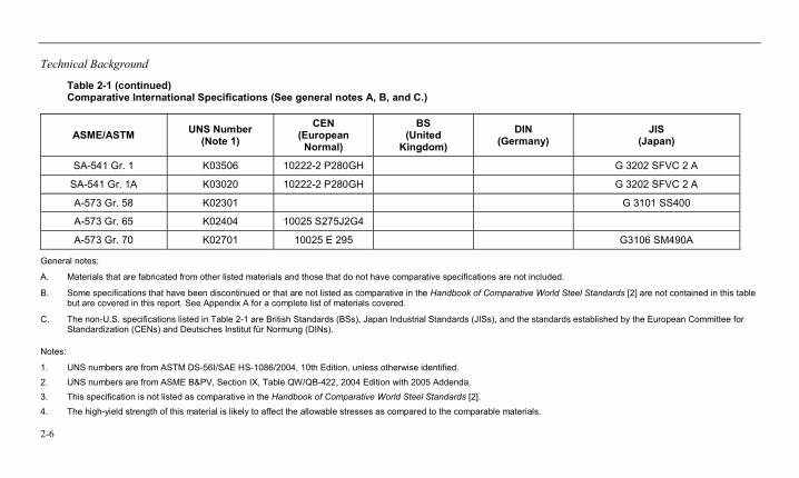
Technical Background
2-6
Table 2-1 (continued) Comparative International Specifications (See general notes A, B, and C.)
ASME/ASTM UNS Number (Note 1)
CEN (European
Normal)
BS (United
Kingdom) DIN
(Germany) JIS
(Japan)
SA-541 Gr. 1 K03506 10222-2 P280GH G 3202 SFVC 2 A
SA-541 Gr. 1A K03020 10222-2 P280GH G 3202 SFVC 2 A
A-573 Gr. 58 K02301 G 3101 SS400
A-573 Gr. 65 K02404 10025 S275J2G4
A-573 Gr. 70 K02701 10025 E 295 G3106 SM490A
General notes:
A. Materials that are fabricated from other listed materials and those that do not have comparative specifications are not included.
B. Some specifications that have been discontinued or that are not listed as comparative in the Handbook of Comparative World Steel Standards [2] are not contained in this table but are covered in this report. See Appendix A for a complete list of materials covered.
C. The non-U.S. specifications listed in Table 2-1 are British Standards (BSs), Japan Industrial Standards (JISs), and the standards established by the European Committee for Standardization (CENs) and Deutsches Institut für Normung (DINs).
Notes:
1. UNS numbers are from ASTM DS-56I/SAE HS-1086/2004, 10th Edition, unless otherwise identified. 2. UNS numbers are from ASME B&PV, Section IX, Table QW/QB-422, 2004 Edition with 2005 Addenda. 3. This specification is not listed as comparative in the Handbook of Comparative World Steel Standards [2]. 4. The high-yield strength of this material is likely to affect the allowable stresses as compared to the comparable materials.
Technical Background
2-7
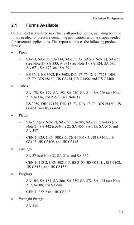
2.1 Forms Available
Carbon steel is available in virtually all product forms, including both the forms needed for pressure-containing applications and the shapes needed for structural applications. This report addresses the following product forms:
• Pipes
– SA-53, SA-106, SA-134, SA-135, A-139 (see Note 1), SA-155 (see Note 2), SA-333, A-381 (see Note 1), SA-524, SA-587, SA-671, SA-672, and SA-691
– BS 3601, BS 3602, BS 3603, DIN 17175, DIN 17173, DIN 17179, DIN 28180, JIS G3454, JIS G3456, and JIS G3460
• Tubes
– SA-178, SA-179, SA-192, SA-210, SA-214, SA-226 (see Note 2), SA-334, and A-573 (see Note 1)
– BS 3059, DIN 17175, DIN 17173, DIN 17179, DIN 28180, JIS G3461, and JIS G3464
• Plates
– SA-212 (see Note 2), SA-283, SA-285, SA-299, SA-433 (see Note 2), SA-442 (see Note 2), SA-455, SA-515, SA-516, and SA-537
– CEN 10025, CEN 10028-2, CEN 10028-5, JIS G3101, JIS G3103, JIS G3106, and JIS G3115
• Castings
– SA-27 (see Note 3), SA-216, and SA-352
– CEN 10213-2, CEN 10213-3, BS 3100, JIS G5101, JIS G5102, JIS G5151, and JIS G5152
• Forgings
– SA-105, SA-181, SA-266, SA-350, SA-372, SA-465 (see Note 2), SA-508, and SA-541
– CEN 10222-2 and JIS G3202
• Wrought fittings
– SA-234
Technical Background
2-8
Notes: 1. There is no ASME material specification, only an ASTM material
specification.
2. The specification or grade has been discontinued: information given is from the last available specification or code. See Table 3-1 for the specific source.
3. Some grades of ASTM A-27 were not accepted in the ASME equivalent (SA-27).
2.2 Applications
Carbon steel is used in boilers, pressure vessels, heat exchangers, piping, and other moderate-temperature service systems in which good strength and ductility are desired. Significant other factors include cost, availability, and the ease of fabrication.
3-1
3 STANDARDS AND CODES
3.1 Specifications
The lists provided in Tables 3-1 and 3-2 identify the specifications covered by this report. In Table 3-1, all specifications listed as SA-nnn are ASME specifications. Those listed as A-nnn are ASTM specifications that have not been adopted by the ASME B&PV Code. However, it should be noted that these steels might have been accepted for use in the ASME Code for Pressure Piping [4], in Code cases, or in structural Codes. Unless otherwise noted, all of the information for the ASME materials was obtained from the ASME B&PV Code, Section II, Part A, 2004 Edition with the 2005 Addenda [5]. For the discontinued specifications and those that are unique to ASTM, the specific source information and the edition year are also noted. The user should recognize that the information can change between different editions of the specifications or Codes referenced.
Table 3-2 identifies the international (non-U.S.) material specifications identified as comparable to a number of the ASME/ASTM specifications covered.
Standards and Codes
3-2
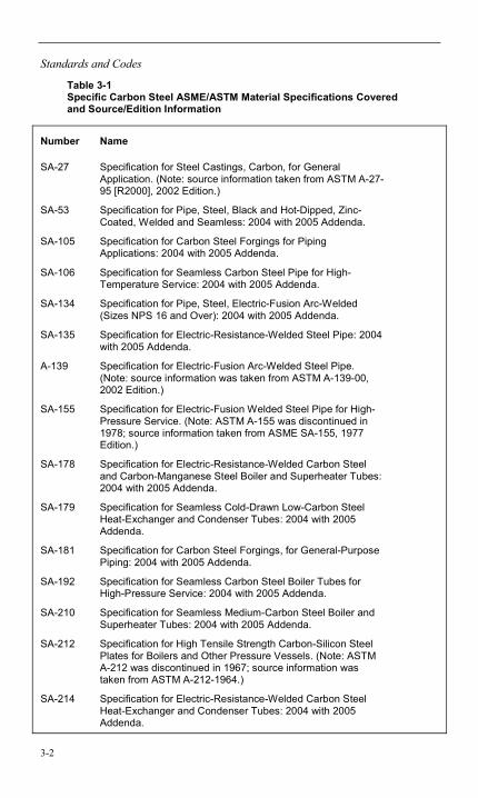
Table 3-1 Specific Carbon Steel ASME/ASTM Material Specifications Covered and Source/Edition Information
Number Name
SA-27 Specification for Steel Castings, Carbon, for General Application. (Note: source information taken from ASTM A-27-95 [R2000], 2002 Edition.)
SA-53 Specification for Pipe, Steel, Black and Hot-Dipped, Zinc-Coated, Welded and Seamless: 2004 with 2005 Addenda.
SA-105 Specification for Carbon Steel Forgings for Piping Applications: 2004 with 2005 Addenda.
SA-106 Specification for Seamless Carbon Steel Pipe for High-Temperature Service: 2004 with 2005 Addenda.
SA-134 Specification for Pipe, Steel, Electric-Fusion Arc-Welded (Sizes NPS 16 and Over): 2004 with 2005 Addenda.
SA-135 Specification for Electric-Resistance-Welded Steel Pipe: 2004 with 2005 Addenda.
A-139 Specification for Electric-Fusion Arc-Welded Steel Pipe. (Note: source information was taken from ASTM A-139-00, 2002 Edition.)
SA-155 Specification for Electric-Fusion Welded Steel Pipe for High-Pressure Service. (Note: ASTM A-155 was discontinued in 1978; source information taken from ASME SA-155, 1977 Edition.)
SA-178 Specification for Electric-Resistance-Welded Carbon Steel and Carbon-Manganese Steel Boiler and Superheater Tubes: 2004 with 2005 Addenda.
SA-179 Specification for Seamless Cold-Drawn Low-Carbon Steel Heat-Exchanger and Condenser Tubes: 2004 with 2005 Addenda.
SA-181 Specification for Carbon Steel Forgings, for General-Purpose Piping: 2004 with 2005 Addenda.
SA-192 Specification for Seamless Carbon Steel Boiler Tubes for High-Pressure Service: 2004 with 2005 Addenda.
SA-210 Specification for Seamless Medium-Carbon Steel Boiler and Superheater Tubes: 2004 with 2005 Addenda.
SA-212 Specification for High Tensile Strength Carbon-Silicon Steel Plates for Boilers and Other Pressure Vessels. (Note: ASTM A-212 was discontinued in 1967; source information was taken from ASTM A-212-1964.)
SA-214 Specification for Electric-Resistance-Welded Carbon Steel Heat-Exchanger and Condenser Tubes: 2004 with 2005 Addenda.
Standards and Codes
3-3
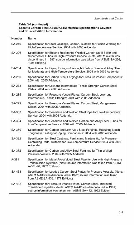
Table 3-1 (continued) Specific Carbon Steel ASME/ASTM Material Specifications Covered and Source/Edition Information
Number Name
SA-216 Specification for Steel Castings, Carbon, Suitable for Fusion Welding for High-Temperature Service: 2004 with 2005 Addenda.
SA-226 Specification for Electric-Resistance-Welded Carbon Steel Boiler and Superheater Tubes for High-Pressure Service. (Note: ASTM A-226 was discontinued in 1997; source information was taken from ASME SA-226, 1998 Edition.)
SA-234 Specification for Piping Fittings of Wrought Carbon Steel and Alloy Steel for Moderate and High-Temperature Service: 2004 with 2005 Addenda.
SA-266 Specification for Carbon Steel Forgings for Pressure Vessel Components: 2004 with 2005 Addenda.
SA-283 Specification for Low and Intermediate Tensile Strength Carbon Steel Plates: 2004 with 2005 Addenda.
SA-285 Specification for Pressure Vessel Plates, Carbon Steel, Low- and Intermediate-Tensile Strength: 2004 with 2005 Addenda.
SA-299 Specification for Pressure Vessel Plates, Carbon Steel, Manganese-Silicon: 2004 with 2005 Addenda.
SA-333 Specification for Seamless and Welded Steel Pipe for Low-Temperature Service: 2004 with 2005 Addenda.
SA-334 Specification for Seamless and Welded Carbon and Alloy-Steel Tubes for Low-Temperature Service: 2004 with 2005 Addenda.
SA-350 Specification for Carbon and Low-Alloy Steel Forgings, Requiring Notch Toughness Testing for Piping Components: 2004 with 2005 Addenda.
SA-352 Specification for Steel Castings, Ferritic and Martensitic, for Pressure-Containing Parts, Suitable for Low-Temperature Service: 2004 with 2005 Addenda.
SA-372 Specification for Carbon and Alloy Steel Forgings for Thin-Walled Pressure Vessels: 2004 with 2005 Addenda.
A-381 Specification for Metal-Arc-Welded Steel Pipe for Use with High-Pressure Transmission Systems. (Note: source information was taken from ASTM A-381-96, 2002 Edition.)
SA-433 Specification for Leaded Carbon Steel Plates for Pressure Vessels. (Note: ASTM A-433 was discontinued in 1972; source information was taken from ASME SA-433, 1971 Edition.)
SA-442 Specification for Pressure Vessel Plates, Carbon Steel, Improved Transition Properties. (Note: ASTM A-442 was discontinued in 1991; source information was taken from ASME SA-442, 1992 Edition.)
Standards and Codes
3-4
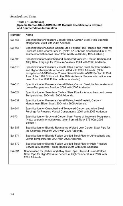
Table 3-1 (continued) Specific Carbon Steel ASME/ASTM Material Specifications Covered and Source/Edition Information
Number Name
SA-455 Specification for Pressure Vessel Plates, Carbon Steel, High-Strength Manganese: 2004 with 2005 Addenda.
SA-465 Specification for Leaded Carbon Steel Forged Pipe Flanges and Parts for Pressure and General Service. (Note: SA-465 was discontinued in 1975; source information was taken from ASTM A-465-68, 1974 Edition.)
SA-508 Specification for Quenched and Tempered Vacuum-Treated Carbon and Alloy Steel Forgings for Pressure Vessels: 2004 with 2005 Addenda.
SA-515 Specification for Pressure Vessel Plates, Carbon Steel, for Intermediate- and Higher-Temperature Service: 2004 with 2005 Addenda. (Note: exception—SA-515 Grade 55 was discontinued in ASME Section II, Part A as of the 1992 Edition with the 1994 Addenda. Source information was taken from the 1992 Edition without addenda.)
SA-516 Specification for Pressure Vessel Plates, Carbon Steel, for Moderate- and Lower-Temperature Service: 2004 with 2005 Addenda.
SA-524 Specification for Seamless Carbon Steel Pipe for Atmospheric and Lower Temperatures: 2004 with 2005 Addenda.
SA-537 Specification for Pressure Vessel Plates, Heat-Treated, Carbon-Manganese-Silicon Steel: 2004 with 2005 Addenda.
SA-541 Specification for Quenched and Tempered Carbon and Alloy Steel Forgings for Pressure Vessel Components: 2004 with 2005 Addenda.
A-573 Specification for Structural Carbon Steel Plates of Improved Toughness. (Note: source information was taken from ASTM A-573-00a, 2002 Edition.)
SA-587 Specification for Electric-Resistance-Welded Low-Carbon Steel Pipe for the Chemical Industry: 2004 with 2005 Addenda.
SA-671 Specification for Electric-Fusion-Welded Steel Pipe for Atmospheric and Lower Temperatures: 2004 with 2005 Addenda.
SA-672 Specification for Electric-Fusion-Welded Steel Pipe for High-Pressure Service at Moderate Temperatures: 2004 with 2005 Addenda.
SA-691 Specification for Carbon and Alloy Steel Pipe, Electric-Fusion-Welded Steel Pipe for High-Pressure Service at High Temperatures: 2004 with 2005 Addenda.
Standards and Codes
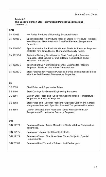
3-5
Table 3-2 The Specific Carbon Steel International Material Specifications Covered [2]
CEN
EN 10025 Hot Rolled Products of Non-Alloy Structural Steels.
EN 10028-2 Specification for Flat Products Made of Steels for Pressure Purposes. Non-Alloy and Alloy Steels with Specified Elevated Temperature Properties.
EN 10028-5 Specification for Flat Products Made of Steels for Pressure Purposes. Weldable Fine Grain Steels, Thermomechanically Rolled.
EN 10213-2 Technical Delivery Conditions for Steel Castings for Pressure Purposes. Steel Grades for Use at Room Temperature and at Elevated Temperature.
EN 10213-3 Technical Delivery Conditions for Steel Castings for Pressure Purposes. Steels for Use at Low Temperatures.
EN 10222-2 Steel Forgings for Pressure Purposes. Ferritic and Martensitic Steels with Specified Elevated Temperature Properties.
BS
BS 3059 Steel Boiler and Superheater Tubes.
BS 3100 Steel Castings for General Engineering Purposes.
BS 3601 Carbon Steel Pipes and Tubes with Specified Room Temperature Properties for Pressure Purposes.
BS 3602 Steel Pipes and Tubes for Pressure Purposes: Carbon and Carbon Manganese Steel with Specified Elevated Temperature Properties.
BS 3603 Carbon and Alloy Steel Pipes and Tubes with Specified Low Temperature Properties for Pressure Purposes.
DIN
DIN 17173 Seamless Circular Tubes Made from Steels with Low Temperature Toughness.
DIN 17175 Seamless Tubes of Heat Resistant Steels.
DIN 17179 Seamless Circular Fine Grain Steel Tubes Subject to Special Requirements.
DIN 28180 Seamless Steel Tubes for Tubular Heat Exchangers.
Standards and Codes
3-6
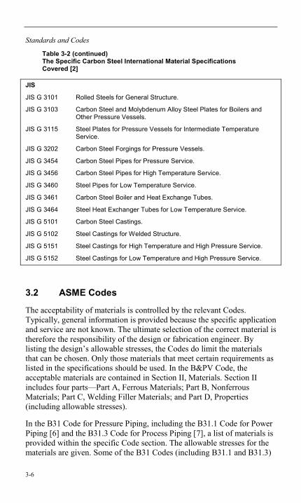
Table 3-2 (continued) The Specific Carbon Steel International Material Specifications Covered [2]
JIS
JIS G 3101 Rolled Steels for General Structure.
JIS G 3103 Carbon Steel and Molybdenum Alloy Steel Plates for Boilers and Other Pressure Vessels.
JIS G 3115 Steel Plates for Pressure Vessels for Intermediate Temperature Service.
JIS G 3202 Carbon Steel Forgings for Pressure Vessels.
JIS G 3454 Carbon Steel Pipes for Pressure Service.
JIS G 3456 Carbon Steel Pipes for High Temperature Service.
JIS G 3460 Steel Pipes for Low Temperature Service.
JIS G 3461 Carbon Steel Boiler and Heat Exchange Tubes.
JIS G 3464 Steel Heat Exchanger Tubes for Low Temperature Service.
JIS G 5101 Carbon Steel Castings.
JIS G 5102 Steel Castings for Welded Structure.
JIS G 5151 Steel Castings for High Temperature and High Pressure Service.
JIS G 5152 Steel Castings for Low Temperature and High Pressure Service.
3.2 ASME Codes
The acceptability of materials is controlled by the relevant Codes. Typically, general information is provided because the specific application and service are not known. The ultimate selection of the correct material is therefore the responsibility of the design or fabrication engineer. By listing the design’s allowable stresses, the Codes do limit the materials that can be chosen. Only those materials that meet certain requirements as listed in the specifications should be used. In the B&PV Code, the acceptable materials are contained in Section II, Materials. Section II includes four parts—Part A, Ferrous Materials; Part B, Nonferrous Materials; Part C, Welding Filler Materials; and Part D, Properties (including allowable stresses).
In the B31 Code for Pressure Piping, including the B31.1 Code for Power Piping [6] and the B31.3 Code for Process Piping [7], a list of materials is provided within the specific Code section. The allowable stresses for the materials are given. Some of the B31 Codes (including B31.1 and B31.3)
Standards and Codes
3-7
allow the use of materials that are not listed. (In the case of B31.1, this has been true only since the 2001 edition.) However, restrictions apply to the use of unlisted materials.
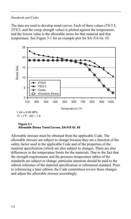
3.2.1 Allowable Stresses
The Code-allowable stresses are determined by the ASME Subcommittee on Materials and are listed in ASME Section II, Part D [8] of the B&PV Code. That organization also determines the allowable stress for the B31 Codes, although those stresses are not published in Section II. The basic rules for acceptance of new materials are contained in the “Guideline on the Approval of New Materials Under the ASME Boiler and Pressure Vessel Code” (found in Section II, Part D, Appendix 5) and in the similar requirements of B31.1, Appendix VI, “Approval of New Materials.” The allowable stresses are based on properties data provided to the Subcommittee from at least three heats of the material. The properties that must be included are the tensile and yield strengths at 100ºF (38ºC) intervals from room temperature to 100ºF (38ºC) above the maximum intended use temperature. Also, if the material is expected to be used in the time-dependent temperature range (that is, creep), creep rate and stress rupture data must be included starting at approximately 50ºF (10ºC) below the temperature at which the time-dependent properties might govern to 100ºF (38ºC) above the maximum use temperature. A duration of at least 6000 hours is required for the creep rupture tests.
The basis for the allowable stresses can vary in different Codes, although the bases are generally the same for most power plant applications. Recent changes to the safety factor in the B&PV Code and in the B31.1 Code have resulted in increased allowable stresses (the safety factor based on tensile strength was reduced from 4 to 3.5). Although different Codes might have different requirements for the allowable stresses, the criteria used to establish the allowable stress for the Code’s Tables 1A and 1B are shown in Table 1-100 of Appendix 1 of ASME Section II, Part D [8]. These criteria follow:
• (1/3.5) x the tensile strength at temperature (2YS/3)
• (2/3) x the yield strength at temperature (TS/3.5)
• A percentage of the creep rupture strength dependent on the testing period
Standards and Codes
3-8
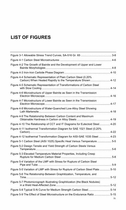
The data are used to develop trend curves. Each of these values (TS/3.5, 2YS/3, and the creep strength value) is plotted against the temperature, and the lowest value is the allowable stress for that material and that temperature. See Figure 3-1 for an example plot for SA-516 Gr. 65.
Figure 3-1 Allowable Stress Trend Curves, SA-516 Gr. 65
Allowable stresses must be obtained from the applicable Code. The allowable stresses are subject to change because they are a function of the safety factor used in the applicable Code and of the properties of the material specification (which are also subject to change). There are also differences in the temperature limits for the materials. Due to the fact that the strength requirements and the pressure-temperature tables of the standards are subject to change, particular attention should be paid to the edition reference of the material specification or referenced standard. Prior to referencing a later edition, the Code committees review these changes and adjust the allowable stresses accordingly.
Standards and Codes
3-9
3.2.2 P Number Identification
The ASME P number is an indication of weldability (see also Section 7.3.1). The ASME B&PV Codes and the B31 Codes all reference ASME Section IX [9] as a standard approach to qualifying welding procedures and welders/welding operators. Section IX designates groups of similar base materials from the weldability standpoint as P numbers (see Section 7.3.1). All of the materials discussed in this report—which include all of the readily weldable carbon steels listed in the B&PV and B31 Codes—carry a P number designation of 1. For the purpose of specific toughness
testing, each set of P number materials is subdivided into groups. The P number 1 materials are divided into groups 1 through 4, which loosely reflect the strength levels of the materials, as follows:
• Group 1: materials with a minimum tensile strength requirement less than 70 ksi (485 MPa)
• Group 2: materials with a minimum tensile strength from 70 ksi (485 MPa) to less than 80 ksi (550 MPa)
• Group 3: materials with a minimum tensile strength from 80 ksi (550 MPa) to less than 90 ksi (620 MPa)
• Group 4: materials with minimum tensile strength properties of more than 90 ksi (620 MPa)
Whereas the purpose of P numbers is to establish qualification material groups based on weldability, the Codes expand the use of the designation into other areas, such as preheat, post-weld heat treatment (PWHT), and bending and forming rules.

4-1
4 METALLURGY
4.1 Chemical Composition
The chemical compositions of the materials are also established by the material specifications for each type or grade of material. The elements that are not identified should not be present in more than trace amounts—except iron, of course, the primary constituent of carbon steels.
The chemical compositions for the ASME carbon steels covered herein are given in Appendix A. Single values are minimums unless otherwise identified, and ranges are given for other elements. The UNS number is listed again for convenience and because the main criteria used to establish that identification is the chemical composition.
The heat analysis is given unless otherwise noted. Although this is the analysis taken from the molten heat and given on the certified material test report, the actual composition of the end product might vary in excess of the heat analysis due to fluctuations that occur during solidification and processing. The limits on the product analysis are therefore somewhat less restrictive than those of the heat analysis.
As previously discussed, the alloying that is used for the materials covered by this report is limited primarily to carbon, manganese, and silicon added in limited and varying percentages to the iron base. In spite of this limited alloying, the properties of the materials are wide-ranging, as described in Section 5. The metallurgical structure and the carbon content are major contributors to the overall properties of the different carbon steel materials. Materials classified as carbon steel might also contain small amounts of other elements, such as chromium, nickel, molybdenum, copper, vanadium, niobium (columbium), phosphorous, and sulfur.
Each element that is added to the basic constituent of iron has some effect on the end properties of the material and how that material reacts to fabrication processes. The alloying additions are responsible for many of
Metallurgy
4-2
the differences between the various types or grades of carbon steels. Following is a list of the elements commonly added to iron and their effects on the material:
• Carbon. Carbon is the most important alloying element in steel and can be present up to 2% (although most welded steels have less than 0.5%). The carbon can exist either dissolved in the iron or in a combined form, such as iron carbide (Fe3C). Increased amounts of carbon increase hardness and tensile strength as well as response to heat treatment (hardenability). On the other hand, increased amounts of carbon reduce weldability.
• Manganese. Steels usually contain at least 0.3% manganese, which acts in a three-fold manner: it assists in deoxidation of the steel, prevents the formation of iron sulfide inclusions, and promotes greater strength by increasing the hardenability of the steel. Amounts up to 1.5% are commonly found in carbon steels.
• Silicon. Usually, only small amounts (0.2%, for example) are present in rolled steel when silicon is used as a deoxidizer. However, in steel castings, 0.35–1.0% is common. Silicon dissolves in iron and tends to strengthen it. Weld metal usually contains approximately 0.5% silicon as a deoxidizer. Some filler metals can contain up to 1.0% to provide enhanced cleaning and deoxidation for welding on contaminated surfaces. When these filler metals are used for welding of clean surfaces, the resulting weld metal strength will be markedly increased. The resulting decrease in ductility could present cracking problems in some situations.
• Sulfur. This is an undesirable impurity in steel rather than an alloying element. Special effort is made to eliminate or minimize sulfur during steelmaking. In amounts exceeding 0.05%, it tends to cause brittleness and reduce weldability. Additions of sulfur in amounts from 0.1% to 0.3% will tend to improve the machinability of steel but impair weldability. These types of steel can be referred to as free-machining.
• Phosphorus. Phosphorus is also considered to be an undesirable impurity in steels. It is normally found in amounts up to 0.04% in most carbon steels. In hardened steels, it tends to cause embrittlement. In low-alloy, high-strength steels, phosphorus can be added in amounts up to 0.10% to improve both strength and corrosion resistance, although it is not generally added for this reason in carbon steels.
Metallurgy
4-3
• Chromium. Chromium is a powerful alloying element in steel. It is added for two principal reasons: first, it greatly increases the hardenability of steel; second, it markedly improves the corrosion resistance of iron and steel in oxidizing types of media. Its presence in some steels could cause excessive hardness and cracking in and adjacent to the weld. Stainless steels contain chromium in amounts exceeding 12%.
• Molybdenum. This element is a strong carbide former and is usually present in alloy steels in amounts less than 1.0%. It is added to increase hardenability and to elevate temperature strength.
• Nickel. Nickel is added to steels to increase their hardenability. It performs well in this function because it often improves the toughness and ductility of the steel, even with the increased strength and hardness. Nickel is frequently used to improve steel toughness at low temperatures.
• Vanadium. The addition of vanadium will result in an increase in the hardenability of steel. It is very effective in this role, so it is generally added in minute amounts. In amounts greater than 0.05%, there can be a tendency for the steel to become embrittled during thermal stress relief treatments.
• Columbium. Columbium (also called niobium), like vanadium, is generally considered to increase the hardenability of steel. However, due to its strong affinity for carbon, it can combine with carbon in the steel to result in an overall decrease in hardenability.
• Other alloying elements. Some carbon steel specifications allow additions of certain other elements, but they are not deliberately added. Other specifications might list these elements as a specified addition to the steel, but the addition would be minor in carbon steels.
4.2 Carbon Equivalence
Carbon is usually considered to be the most important contributor to the hardness and strength of ferrous steels. Even when other alloying elements are not present, high carbon content can result in high local hardnesses. However, other alloying elements also contribute to the overall hardenability of the steel. This effect can be generally quantified by the determination of the carbon equivalence (CE) of the steel.
Metallurgy
4-4
CE is defined by several formulas, and it is important that close attention be paid to the formula being used. The following formula is used in most ASME applications:
CE = C + (Mn + Si)/6 + (Cr + Mo + V)/5 + (Ni + Cu)/15
It is important that any CE determination be calculated using the actual chemical analysis rather than the maximums specified in materials specifications. If this is not done, the calculation will result in an unrealistically high CE [10].
The CE can be specified at certain maximum values (for example, SA-537 Class 1; see Appendix A) and can be applied to a variety of fabrication variables. These are covered within the discussion of those variables.
4.3 Microstructure and Heat Treatment
4.3.1 Microstructure
Metallic materials take the form of a crystalline structure in the solid state (with the exception of amorphous metals that have been formed under radical cooling conditions, unlike those that occur in normal processing). The crystalline structure and the alloying elements added to pure iron give carbon steel the ability to have a wide range of properties, which make it one of the most useful materials in industry today. The crystalline structure of carbon steel might include body-centered cubic (ferrite), face-centered cubic (austenite), or body-centered tetragonal (martensite) forms.
The crystalline structure forms in many directions during solidification from the molten state of the material. Solidification starts from initiation points and continues until the crystalline structure that is formed runs into another island that started from a different point. Each of these islands of a single orientation is a grain that exists as a singular structure. The size of these grains also contributes to the properties of the material and as will be discussed, also affects the ability of the material to form certain microstructures. As the material cools, carbon steel crystalline structures are forced to change from one structure to another—these are called phase transformations. The different structures have different limits of solubility of the alloying elements, primarily carbon in carbon steels. The microstructure can also contain other compounds, such as metallic carbides, interspersed with the crystalline form. The complex microstructure of carbon steel includes the crystalline structure, the grain size, and the size and frequency of the interspersed metallic compounds.
Metallurgy
4-5
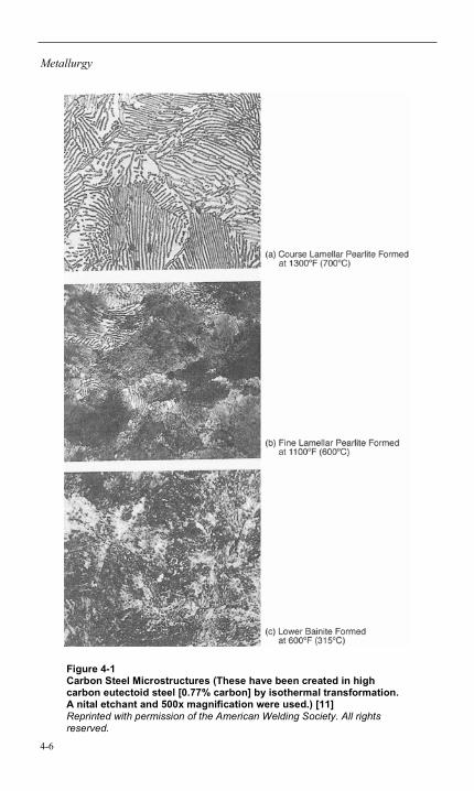
Carbon steels can exist in different microstructures or combinations of microstructures. The microstructures of carbon steels include not only the crystalline structure but also various metallic carbides or compounds in different arrangements. Pearlite, upper bainite, and lower bainite are examples of the arrangements that can exist (see Figure 4-1).
Metallurgy
4-6
Figure 4-1 Carbon Steel Microstructures (These have been created in high carbon eutectoid steel [0.77% carbon] by isothermal transformation. A nital etchant and 500x magnification were used.) [11] Reprinted with permission of the American Welding Society. All rights reserved.
Metallurgy
4-7
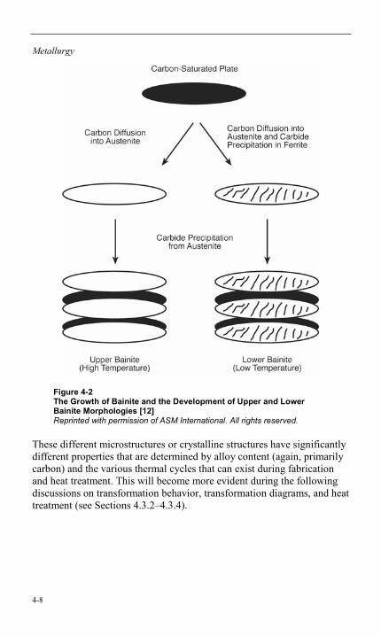
The mechanism by which the arrangements in Figure 4-1 were formed will be covered in Section 4.3.2, but the following is a brief description of each of these microstructures.
Pearlite is an arrangement of thin alternating and roughly parallel lamellar platelets of ferritic (body-centered cubic) structures with iron carbides (Fe3C) called cementite. The lamellar platelets can be coarse or fine, but they are often recognizable with optical microscopy. Bainite is an arrangement of aggregates of ferrite with distributions of precipitated carbide particles. However, the arrangement can take different forms, thus the terms upper bainite and lower bainite. Upper bainite consists of small ferrite grains that form in plate-shaped sheaths. These grains are interspersed with the cementite that forms at relatively high temperatures. Lower bainite consists of needlelike ferrite plates containing a dispersion of very small carbide particles (see Figure 4-1). (Note that the 0.77% carbon material used to illustrate these structures is not the low- to medium-carbon steels of this report.) An illustration of the growth of upper and lower bainite appears in Figure 4-2.
Metallurgy
4-8
Figure 4-2 The Growth of Bainite and the Development of Upper and Lower Bainite Morphologies [12] Reprinted with permission of ASM International. All rights reserved.
These different microstructures or crystalline structures have significantly different properties that are determined by alloy content (again, primarily carbon) and the various thermal cycles that can exist during fabrication and heat treatment. This will become more evident during the following discussions on transformation behavior, transformation diagrams, and heat treatment (see Sections 4.3.2–4.3.4).
Metallurgy
4-9
4.3.2 Transformation Behavior
The crystalline structure of pure iron is ferrite at room temperature. The room temperature form of ferrite is called alpha (α) ferrite. At higher temperatures, the ferritic structure is unstable and transforms into a face-centered cubic structure called gamma (γ) austenite. At even higher temperatures, the austenitic structure might again transform into a higher temperature form of ferrite; this is called delta (δ) ferrite.
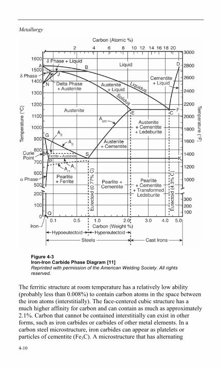
Iron-iron carbide phase diagrams (see Figure 4-3) represent the crystalline structures, or phases, of the carbon steels in an equilibrium state that are determined by very slow cooling from molten material. This is not a realistic view of the microstructural phases that exist during normal fabrication processes because the heating and cooling rates significantly affect the temperatures at which the suggested phase transformations occur. This effect can be seen in the temperature difference between A1, the equilibrium lower transformation temperature, and Ar1, the lower transformation temperature upon cooling. Although not shown, there is also a lower transformation temperature upon heating, Ac1, which is somewhat higher than A1. The Ac1 temperatures depict the start point of the transformation between the α ferrite and the γ austenite upon heating. The phase diagram in Figure 4-3 also shows an equilibrium upper transformation temperature—A3. Similar to the variations noted for A1, there are also upper transformation temperatures upon heating and cooling (Ac3 and Ar3, respectively). The transformation temperatures indicate the points at which the structure becomes an unstable form and begins to undergo a transformation to a different crystalline structure. It can be seen that carbon steels, with a typical maximum carbon content of less than 0.35% for pressure-containing applications, will have a transformation temperature range that will vary with the carbon content and the rate of heating or cooling.
Metallurgy
4-10
Figure 4-3 Iron-Iron Carbide Phase Diagram [11] Reprinted with permission of the American Welding Society. All rights reserved.
The ferritic structure at room temperature has a relatively low ability (probably less than 0.008%) to contain carbon atoms in the space between the iron atoms (interstitially). The face-centered cubic structure has a much higher affinity for carbon and can contain as much as approximately 2.1%. Carbon that cannot be contained interstitially can exist in other forms, such as iron carbides or carbides of other metal elements. In a carbon steel microstructure, iron carbides can appear as platelets or particles of cementite (Fe3C). A microstructure that has alternating
Metallurgy
4-11
platelets of ferrite and cementite is called pearlite. With certain rates of cooling, the carbon steel microstructure can also be bainite. Bainitic structures represent a variety of ferrite aggregates with a distribution of small iron carbide precipitates.
Upon heating the carbon steel microstructure through the transformation range, the ferrite will transform into an austenitic structure. Because the austenitic structure has a much higher solubility of carbon, the iron carbides dissolve and the carbon enters into solution with the austenitic iron microstructure. This is a time- and temperature-dependent mechanism that takes longer if the cementite particles or platelets are large. An increased rate of heating will also have the effect of requiring a higher temperature to complete the dissolution. See Figure 4-4 for an illustration of the transformations that are expected when low-carbon steel is heated rapidly.
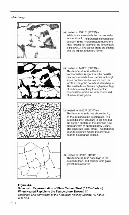
Metallurgy
4-12
Figure 4-4 Schematic Representation of Plain Carbon Steel (0.20% Carbon) When Heated Rapidly to the Temperature Shown [11] Reprinted with permission of the American Welding Society. All rights reserved.
Metallurgy
4-13
Shortly after full austenization has been completed and upon the temperature reaching a point slightly above the upper transformation temperature Ac3, the grain size will be quite small. Upon subsequent cooling, this fine grain structure will be essentially maintained. However, if the metal is heated to a higher temperature before cooling, the grain size will be larger, and the result will be a coarser grain structure in the room temperature structure. The temperature reached during thermal cycles upon heating above the transformation temperatures (such as during a welding process) will therefore have a significant effect on the end properties of the material.
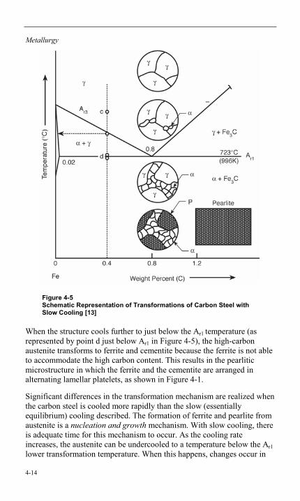
Transformations of even greater significance occur during cooling from the austenitic structure of carbon steel. As previously discussed, the austenitic structure can contain a much higher level of carbon than the ferritic structure, which can contain a maximum of only about 0.008% carbon. When austenitized carbon steel is cooled very slowly (when it is equilibrium cooled, essentially), ferrite grains begin to form just below the Ar3 (the upper transformation temperature upon cooling). These ferrite grains cannot contain the typical carbon content levels of carbon steel; as a result, the content increases in the austenite grains—the reverse of what happens when the ferritic grains are heated through the transformation temperatures shown in Figures 4-4a and 4-4b. As the material is cooled further toward the Ar1 (the lower transformation temperature upon cooling), more ferrite is formed at the grain boundaries of the austenite, and the austenite continues to gain carbon content. This can continue until the Ar1 temperature is reached, at which point the austenite can contain as much as about 0.77% carbon (the eutectoid composition). This can be seen in Figure 4-5 in the illustrations from point c down to point d just above the Ar1 temperature (marked as 723ºC).
Metallurgy
4-14
Figure 4-5 Schematic Representation of Transformations of Carbon Steel with Slow Cooling [13]
When the structure cools further to just below the Ar1 temperature (as represented by point d just below Ar1 in Figure 4-5), the high-carbon austenite transforms to ferrite and cementite because the ferrite is not able to accommodate the high carbon content. This results in the pearlitic microstructure in which the ferrite and the cementite are arranged in alternating lamellar platelets, as shown in Figure 4-1.
Significant differences in the transformation mechanism are realized when the carbon steel is cooled more rapidly than the slow (essentially equilibrium) cooling described. The formation of ferrite and pearlite from austenite is a nucleation and growth mechanism. With slow cooling, there is adequate time for this mechanism to occur. As the cooling rate increases, the austenite can be undercooled to a temperature below the Ar1 lower transformation temperature. When this happens, changes occur in
Metallurgy
4-15
the microstructure of the material. The effects of the cooling rates are discussed more fully in Section 4.3.3. Following is a discussion of the various microstructures that might result from this more rapid cooling.
Equilibrium cooling of typical carbon steel results in a ferritic structure with grains of pearlite. In this case, the carbon in the austenite has the time to diffuse into the cementite platelets and to allow the ferrite platelets to form. The result is a coarse pearlite with ferrite grains that formed at the grain boundaries. If the austenite is undercooled slightly before transformation can occur, the result is a finer pearlitic structure because the time for the carbon to diffuse into the cementite platelets is shortened. Also, the nodules of pearlite and the grains of ferrite tend to be smaller. Strength and hardness are increased as a result.
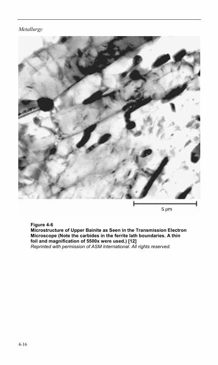
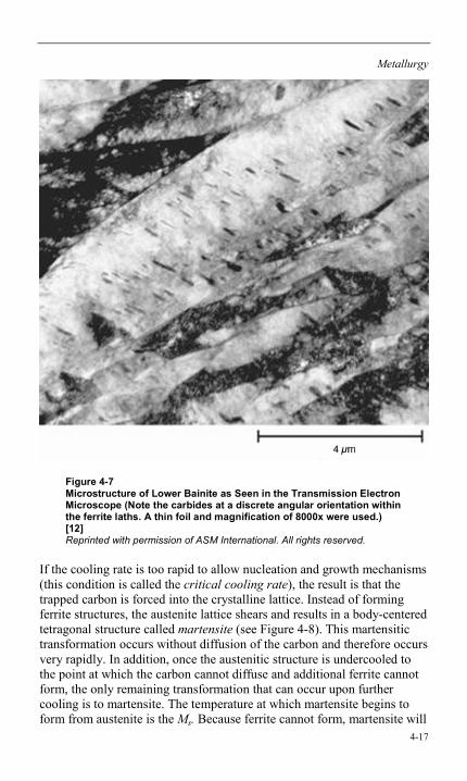
The existence of bainitic structures is possible in carbon steels. Bainitic structures occur when the undercooling of the austenite is such that pearlite can no longer form and the formation of martensite has not yet started (that is, the martensite start temperature [Ms] has not been reached). Bainite can take different morphologies (patterns) as either upper bainite (see Figure 4-6) or lower bainite (see Figure 4-7), depending on the temperature at which it forms. Upper bainite will be somewhat harder and tougher than the pearlite if it forms. Lower bainite will not be as hard as martensite but can be much tougher [11].
Metallurgy
4-16
Figure 4-6 Microstructure of Upper Bainite as Seen in the Transmission Electron Microscope (Note the carbides in the ferrite lath boundaries. A thin foil and magnification of 5500x were used.) [12] Reprinted with permission of ASM International. All rights reserved.
Metallurgy
4-17
Figure 4-7 Microstructure of Lower Bainite as Seen in the Transmission Electron Microscope (Note the carbides at a discrete angular orientation within the ferrite laths. A thin foil and magnification of 8000x were used.) [12] Reprinted with permission of ASM International. All rights reserved.
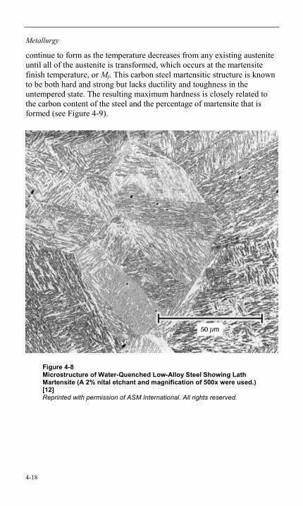
If the cooling rate is too rapid to allow nucleation and growth mechanisms (this condition is called the critical cooling rate), the result is that the trapped carbon is forced into the crystalline lattice. Instead of forming ferrite structures, the austenite lattice shears and results in a body-centered tetragonal structure called martensite (see Figure 4-8). This martensitic transformation occurs without diffusion of the carbon and therefore occurs very rapidly. In addition, once the austenitic structure is undercooled to the point at which the carbon cannot diffuse and additional ferrite cannot form, the only remaining transformation that can occur upon further cooling is to martensite. The temperature at which martensite begins to form from austenite is the Ms. Because ferrite cannot form, martensite will
Metallurgy
4-18
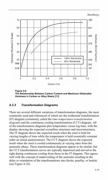
continue to form as the temperature decreases from any existing austenite until all of the austenite is transformed, which occurs at the martensite finish temperature, or Mf. This carbon steel martensitic structure is known to be both hard and strong but lacks ductility and toughness in the untempered state. The resulting maximum hardness is closely related to the carbon content of the steel and the percentage of martensite that is formed (see Figure 4-9).
Figure 4-8 Microstructure of Water-Quenched Low-Alloy Steel Showing Lath Martensite (A 2% nital etchant and magnification of 500x were used.) [12] Reprinted with permission of ASM International. All rights reserved.
Metallurgy
4-19
Figure 4-9 The Relationship Between Carbon Content and Maximum Obtainable Hardness in Carbon or Alloy Steels [11]
4.3.3 Transformation Diagrams
There are several different variations of transformation diagrams, the most commonly used and referenced of which are the isothermal transformation (IT) diagram (commonly called the time-temperature-transformation diagram) and the continuous cooling transformation (CCT) diagram. All of the transformation diagrams plot temperature versus log time, with the display showing the expected crystalline structures and microstructures. The IT diagram shows the expected result when the steel is held for varying lengths of time while the temperature is held essentially constant (after an initial austenization). The CCT diagram shows the expected result when the steel is cooled continuously at varying rates from the austenitic phase. These transformation diagrams appear to be similar, but the CCT transformation curves are typically depressed and moved to the right during continuous cooling from those in the IT diagram. This agrees well with the concept of undercooling of the austenite resulting in the delay or retardation of the transformations into ferrite, pearlite, or bainite (see Figure 4-10).
Metallurgy
4-20
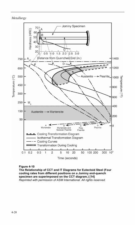
Figure 4-10 The Relationship of CCT and IT Diagrams for Eutectoid Steel (Four cooling rates from different positions on a Jominy end-quench specimen are superimposed on the CCT diagram.) [14] Reprinted with permission of ASM International. All rights reserved.
Metallurgy
4-21
The Jominy end-quench test is related to the CCT diagram because the specimen is raised to an austenitizing temperature and then quenched on one end with water. The result is a varying cooling rate along the specimen that can then be plotted on the CCT to determine the expected microstructure. Hardness readings taken at points along the specimen can then be used to determine the hardenability of the steel.
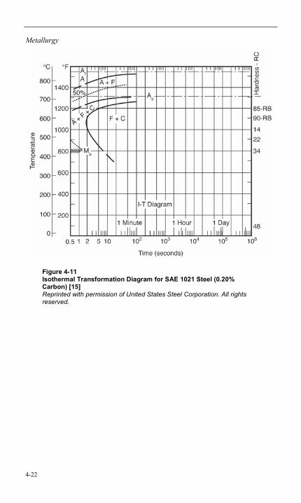
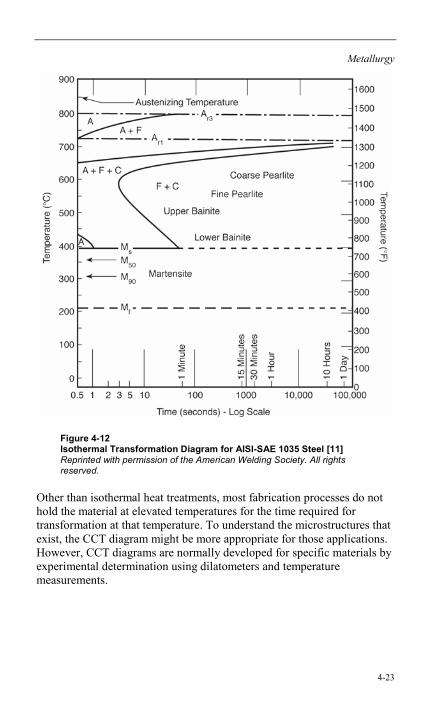
The IT diagram is useful in helping to predict the resulting microstructures if the steel is held at certain temperatures above the Ms temperature for a period of time, such as could be done by quenching the steel in a high-temperature bath of molten salt or metal. Figure 4-11 and Figure 4-12 are IT diagrams for carbon steel with about 0.20% and 0.35% carbon, respectively, that can be used as examples. (AISI is the American Iron and Steel Institute and SAE is the Society of Automotive Engineers International.) The transformation curves for the 0.20% carbon steel are farther to the left than the 0.35% carbon steel. This shows that the transformation would occur faster (as would be expected because not as much carbon would need to diffuse) and that it would be more difficult to avoid transformations upon cooling to the isothermal temperatures. If the 0.35% carbon steel is quenched rapidly down to approximately 1110ºF (600ºC) from the austenitizing temperature and held at that temperature, the following would be expected. Initially, the austenite would not have the time to transform into ferrite or cementite (F or C in Figures 4-11 and 4-12). Shortly after reaching that temperature, the austenite would start to transform into ferrite at the grain boundaries until about 3 seconds elapse at which time ferrite and cementite would begin to form a coarse pearlitic microstructure. If instead the steel were quenched to about 930ºF (500ºC), the material would form an upper bainitic microstructure (although the bainite would not start to form for approximately 10 seconds). If quenched to less than the Ms temperature of about 750ºF (400ºC), martensite would form nearly immediately (because the transformation to martensite is by shear rather than by diffusion or nucleation and growth) to the percentage indicated by the temperature. This transformation of austenite to martensite would become complete when the steel is cooled to below the Mf temperature.
Metallurgy
4-22
Figure 4-11 Isothermal Transformation Diagram for SAE 1021 Steel (0.20% Carbon) [15] Reprinted with permission of United States Steel Corporation. All rights reserved.
Metallurgy
4-23
Figure 4-12 Isothermal Transformation Diagram for AISI-SAE 1035 Steel [11] Reprinted with permission of the American Welding Society. All rights reserved.
Other than isothermal heat treatments, most fabrication processes do not hold the material at elevated temperatures for the time required for transformation at that temperature. To understand the microstructures that exist, the CCT diagram might be more appropriate for those applications. However, CCT diagrams are normally developed for specific materials by experimental determination using dilatometers and temperature measurements.
Metallurgy
4-24
4.3.4 Heat Treatment
The transformation of carbon steel from one microstructure or crystalline structure to another also makes the material heat treatable, or in other words, it allows for changes in the properties of the material just by going through various heating and cooling cycles, without a change in the overall chemical composition of the material. This characteristic can also result in property changes occurring during fabrication processes such as hot bending/forming, welding, and brazing.
The material specifications provide the heat treatments required to achieve the properties necessary for the specific material. Heat treatment is highly dependent on the manufacturing methods used for that product, and the requirements can range from no required heat treatment to subcritical heat treatments (such as precipitation heat treatment, tempering, or stress relief) to high-temperature (austenitizing) heat treatments (such as quench hardening, annealing, or normalizing) that might be followed by a tempering heat treatment. If no heat treatment is required, the properties of the material are dependent on the steelmaking practice, the chemistry, and the fabrication processes used. Descriptions of common heat treatments follow:
• Annealing. Annealing is a very broad term used to describe a variety of heat treatments, but it is a process customarily applied to remove stresses or work hardening. For the purpose of the heat treatment used on carbon steels in the material specifications, the more specific term full annealing better describes the process. Full annealing is defined as “annealing a steel object by austenitizing it and then cooling it slowly through the transformation range” [16]. The result is that the maximum transformation to ferrite and to coarse pearlite is achieved, which corresponds to the lowest hardness and strength. Full annealing of carbon steels would likely require the material to be heated to 1550–1650ºF (845–900ºC) for 1 hour 30 minutes for each additional 1 in. (25.4 mm) above 1-in. (25.4-mm) thickness.
• Normalizing. Normalizing is a specific term defined as “heating a steel object to a suitable temperature above the transformation range and then cooling it in air to a temperature substantially below the transformation range” [16]. For many of the carbon steels discussed in this report, the cooling rate in air is not rapid enough to prevent significant transformation from austenite into ferrite and a pearlitic microstructure. Higher alloy, air-hardenable materials can be significantly hardened by normalizing. The normalizing temperature is typically 100ºF (55ºC) above the upper critical temperature.
Metallurgy
4-25
• Hardening. Quench hardening is often used prior to a tempering heat treatment. It is defined as “hardening a steel object by austenitizing it and then cooling it rapidly enough that some or all of the austenite transforms to martensite” [16]. Quench hardening is normally the first step in a heat treatment that would then include a tempering heat treatment. The martensitic steel is excessively hard and strong with characteristic low toughness, so the tempering treatment is used to recover some of the more desirable properties. The carbon steel material is typically heated to 1500–1600ºF (815–870ºC) and quenched in a medium selected to cause the desired cooling rate.
• Tempering. Tempering is defined as “reheating a quench hardened or normalized steel object to a temperature below Ac1 and then cooling it at any desired rate” [16]. Tempering allows some of the carbon atoms in the strained martensitic structure to diffuse and form iron carbides or cementite. This reduces the hardness, tensile strength, yield strength, and stress level but increases the ductility and toughness. Tempering temperatures and times are interdependent, but tempering is normally done at temperatures between 350°F and 1300°F (175°C and 705°C) and for times from 30 minutes to 4 hours.
• Stress relieving. Stress relieving is often associated with tempering and can occur simultaneously with tempering. It is defined as “heating a steel object to a suitable temperature, holding it long enough to reduce residual stresses, and then cooling it slowly enough to minimize the development of new residual stresses” [16]. Locked-in (residual) stresses in a component cannot exist at a greater level than the yield strength of the material. An increase in the temperature of steel lowers the yield strength and thus relieves some of the stresses. Further reduction in the residual stress can occur due to a creep mechanism at high stress relief temperatures. Stress relieving has a time-temperature relationship similar to tempering. Although some stress relief occurs very quickly as a result of the lower yield strength at temperature, additional stress relief occurs by the primary creep mechanism (see Section 5.3). Stress relief temperatures are typically 1100–1250ºF (595–675ºC) for carbon steels.
Metallurgy
4-26
• Precipitation heat treatment. Precipitation heat treatment is less common in carbon steels because the precipitates desired are generally carbides of alloying elements other than iron. However, some of the carbon steels include a small amount of those elements, such as chromium, molybdenum, niobium, or vanadium. Precipitation heat treatment is defined as “artificial aging in which a constituent precipitates from a supersaturated solid solution” [16]. Because precipitation hardening is not normally used to increase the strength of carbon steels, this does not apply.
5-1
5 PROPERTIES
5.1 Physical Properties
The following physical properties have been compiled from several publications [6, 8, 17, 18]:
• Mean coefficient of linear thermal expansion: the ratio of the change in length to the original length at a reference temperature, T0, per degree of temperature change, where T0 is normally room temperature. If l0 is the length at T0 and alpha (α) is the mean coefficient of linear thermal expansion, the length at temperature T, lt, is given by
lt = l0[1 + α(T-T0)] [19]
• Instantaneous coefficient of linear thermal expansion: the rate of the change in length at a specific temperature.
• Linear thermal expansion: the change in length over a specific temperature range per 100 ft (30.5 m).
• Modulus of elasticity (E): (1) the measure of rigidity or stiffness of a material; the ratio of stress below the proportional limit to the corresponding strain or (2) the slope of a stress-strain curve in the range of linear proportionality of stress to strain. Also known as Young’s modulus [20].
• Thermal conductivity: the quantity of heat transmitted, k, due to unit temperature gradient, in unit time under steady conditions in a direction normal to a surface of unit area and when the heat transfer is solely dependent on the temperature gradient [19].
• Thermal diffusivity: the constant in the heat conduction equation describing the rate at which heat is conducted through a material. It is linked to thermal conductivity, k, specific heat, Cp, and density, ρ, through the equation
Thermal diffusivity = k / ρCp [19]
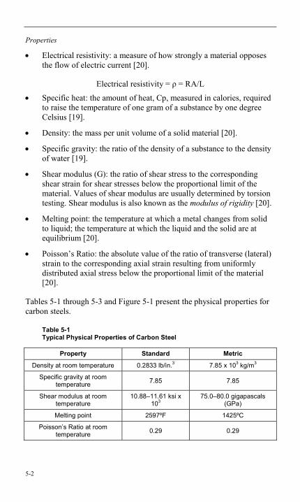
Properties
5-2
• Electrical resistivity: a measure of how strongly a material opposes the flow of electric current [20].
Electrical resistivity = ρ = RA/L
• Specific heat: the amount of heat, Cp, measured in calories, required to raise the temperature of one gram of a substance by one degree Celsius [19].
• Density: the mass per unit volume of a solid material [20].
• Specific gravity: the ratio of the density of a substance to the density of water [19].
• Shear modulus (G): the ratio of shear stress to the corresponding shear strain for shear stresses below the proportional limit of the material. Values of shear modulus are usually determined by torsion testing. Shear modulus is also known as the modulus of rigidity [20].
• Melting point: the temperature at which a metal changes from solid to liquid; the temperature at which the liquid and the solid are at equilibrium [20].
• Poisson’s Ratio: the absolute value of the ratio of transverse (lateral) strain to the corresponding axial strain resulting from uniformly distributed axial stress below the proportional limit of the material [20].
Tables 5-1 through 5-3 and Figure 5-1 present the physical properties for carbon steels.
Table 5-1 Typical Physical Properties of Carbon Steel
Property Standard Metric
Density at room temperature 0.2833 lb/in.3 7.85 x 10³ kg/m3
Specific gravity at room temperature 7.85 7.85
Shear modulus at room temperature
10.88–11.61 ksi x 103
75.0–80.0 gigapascals (GPa)
Melting point 2597ºF 1425ºC
Poisson’s Ratio at room temperature 0.29 0.29
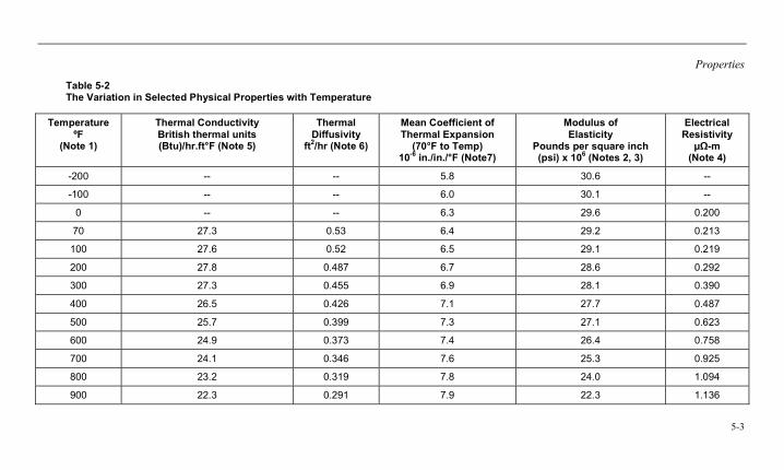
Properties
5-3
Table 5-2 The Variation in Selected Physical Properties with Temperature
Temperature ºF
(Note 1)
Thermal Conductivity British thermal units (Btu)/hr.ft°F (Note 5)
Thermal Diffusivity
ft2/hr (Note 6)
Mean Coefficient of Thermal Expansion
(70°F to Temp) 10-6 in./in./°F (Note7)
Modulus of Elasticity
Pounds per square inch (psi) x 106 (Notes 2, 3)
Electrical Resistivity
µΩ-m (Note 4)
-200 -- -- 5.8 30.6 --
-100 -- -- 6.0 30.1 --
0 -- -- 6.3 29.6 0.200
70 27.3 0.53 6.4 29.2 0.213
100 27.6 0.52 6.5 29.1 0.219
200 27.8 0.487 6.7 28.6 0.292
300 27.3 0.455 6.9 28.1 0.390
400 26.5 0.426 7.1 27.7 0.487
500 25.7 0.399 7.3 27.1 0.623
600 24.9 0.373 7.4 26.4 0.758
700 24.1 0.346 7.6 25.3 0.925
800 23.2 0.319 7.8 24.0 1.094
900 22.3 0.291 7.9 22.3 1.136
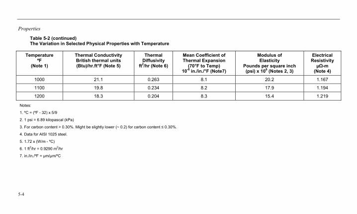
Properties
5-4
Table 5-2 (continued) The Variation in Selected Physical Properties with Temperature
Temperature ºF
(Note 1)
Thermal Conductivity British thermal units (Btu)/hr.ft°F (Note 5)
Thermal Diffusivity
ft2/hr (Note 6)
Mean Coefficient of Thermal Expansion
(70°F to Temp) 10-6 in./in./°F (Note7)
Modulus of Elasticity
Pounds per square inch (psi) x 106 (Notes 2, 3)
Electrical Resistivity
µΩ-m (Note 4)
1000 21.1 0.263 8.1 20.2 1.167
1100 19.8 0.234 8.2 17.9 1.194
1200 18.3 0.204 8.3 15.4 1.219
Notes:
1. ºC = (ºF - 32) x 5/9
2. 1 psi = 6.89 kilopascal (kPa)
3. For carbon content > 0.30%. Might be slightly lower (~ 0.2) for carbon content ≤ 0.30%.
4. Data for AISI 1025 steel.
5. 1.72 x (W/m - ºC)
6. 1 ft2/hr = 0.9290 m2/hr
7. in./in./ºF = µm/µm/ºC
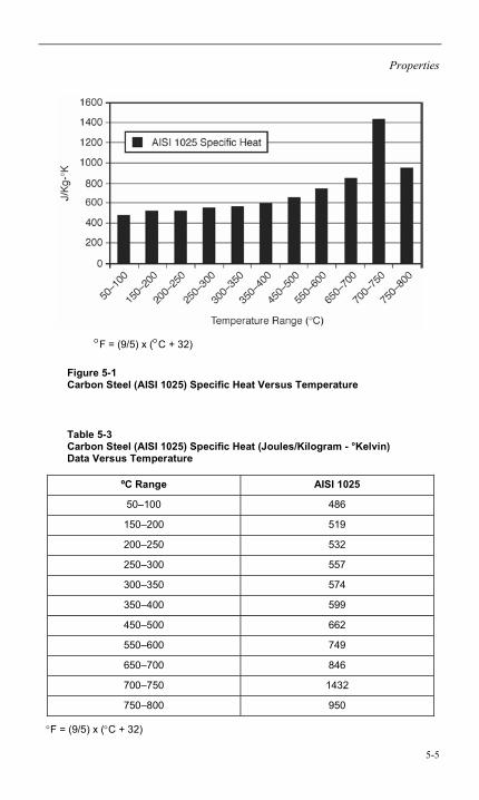
Properties
5-5
°F = (9/5) x (°C + 32)
Figure 5-1 Carbon Steel (AISI 1025) Specific Heat Versus Temperature
Table 5-3 Carbon Steel (AISI 1025) Specific Heat (Joules/Kilogram - °Kelvin) Data Versus Temperature
ºC Range AISI 1025
50–100 486
150–200 519
200–250 532
250–300 557
300–350 574
350–400 599
450–500 662
550–600 749
650–700 846
700–750 1432
750–800 950
°F = (9/5) x (°C + 32)
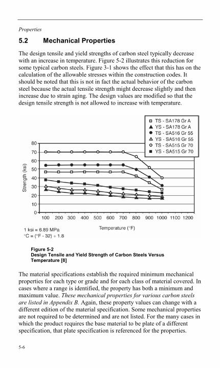
Properties
5-6
5.2 Mechanical Properties
The design tensile and yield strengths of carbon steel typically decrease with an increase in temperature. Figure 5-2 illustrates this reduction for some typical carbon steels. Figure 3-1 shows the effect that this has on the calculation of the allowable stresses within the construction codes. It should be noted that this is not in fact the actual behavior of the carbon steel because the actual tensile strength might decrease slightly and then increase due to strain aging. The design values are modified so that the design tensile strength is not allowed to increase with temperature.
Figure 5-2 Design Tensile and Yield Strength of Carbon Steels Versus Temperature [8]
The material specifications establish the required minimum mechanical properties for each type or grade and for each class of material covered. In cases where a range is identified, the property has both a minimum and maximum value. These mechanical properties for various carbon steels are listed in Appendix B. Again, these property values can change with a different edition of the material specification. Some mechanical properties are not required to be determined and are not listed. For the many cases in which the product requires the base material to be plate of a different specification, that plate specification is referenced for the properties.
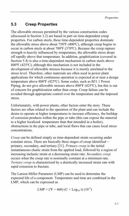
Properties
5-7
5.3 Creep Properties
The allowable stresses permitted by the various construction codes (discussed in Section 3.2) are based in part on time-dependent creep properties. For carbon steels, these time-dependent properties dominate the allowable stress above about 750ºF (400ºC), although creep begins to occur in carbon steels at about 700ºF (370ºC). Because the creep rupture strength is heavily influenced by temperature, the allowable stress drops off rapidly above that temperature. In addition, graphitization (covered in Section 5.4) is also a time-dependent mechanism in carbon steels above 800ºF (425ºC), although this mechanism is not included in the development of allowable stresses because it is mostly unrelated to the stress level. Therefore, other materials are often used in power plant applications for which continuous operation is expected at or near a design temperature above 800ºF (425ºC). Some codes, such as B31.1 Power Piping, do not give allowable stresses above 800ºF (425ºC), but this is out of concern for graphitization rather than creep. Creep failure can be avoided through appropriate control over the temperature and the imposed stress.
Unfortunately, with power plants, other factors enter the story. These factors are often related to the operation of the plant and can include the desire to operate at higher temperatures to increase efficiency, the buildup of corrosion products within the pipe or tube (this can expose the material to a higher localized temperature than that intended in a boiler), obstructions in the pipe or tube, and local flaws that can cause local stress concentrations.
Creep can be defined simply as time-dependent strain occurring under constant stress. There are basically three stages of creep identified—primary, secondary, and tertiary [21]. Primary creep is the initial instantaneous elastic strain from the applied load, followed by a region of increasing inelastic strain at a decreasing strain rate. Secondary creep occurs when the creep rate is nominally constant at a minimum rate. Tertiary creep is characterized by a drastically increased strain rate with rapid extension to fracture.
The Larson-Miller Parameter (LMP) can be used to determine the expected life of a component. Temperature and time are combined in the LMP, which can be expressed as
LMP = (ºF + 460) (C + Log10 t) (10-3)
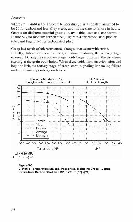
Properties
5-8
where (ºF + 460) is the absolute temperature, C is a constant assumed to be 20 for carbon and low-alloy steels, and t is the time to failure in hours. Graphs for different material groups are available, such as those shown in Figure 5-3 for medium carbon steel, Figure 5-4 for carbon steel pipe or tube, and Figure 5-5 for carbon steel plate.
Creep is a result of microstructural changes that occur with stress. Initially, dislocations occur in the grain structure during the primary stage of creep. During the secondary stage, voids begin to form in the structure, starting at the grain boundaries. When these voids form an orientation and begin to link, the tertiary stage of creep starts, signaling impending failure under the same operating conditions.
Figure 5-3 Elevated Temperature Material Properties, Including Creep Rupture for Medium Carbon Steel (In LMP, C=20, T [°R].) [22]
Properties
5-9
Figure 5-4 Variation of the LMP with Stress for Rupture of Carbon Steel Pipe and Tube [23]

Properties
5-10
Figure 5-5 Variation of LMP with Stress for Rupture of Carbon Steel Plate [23]
Creep failures can occur in carbon steel materials when subjected to long-term overheating while under stress. Although carbon steel materials are generally not used under conditions where creep is expected, a number of factors can cause the material to see higher temperatures than expected, particularly within a boiler with a heat source external to the material. The buildup of an internal oxide scale or tube blockage can cause this
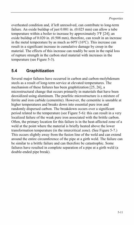
Properties
5-11
overheated condition and, if left unresolved, can contribute to long-term failure. An oxide buildup of just 0.001 in. (0.025 mm) can allow a tube temperature within a boiler to increase by approximately 3ºF [24]; an oxide buildup of 0.020 in. (0.508 mm), therefore, can result in an increase in the metal temperature by as much as 60ºF (16ºC). This increase can result in a significant increase in cumulative damage by creep in the material. The effects of this increase can readily be seen in the rapid loss of rupture strength in the carbon steel material with increases in the temperature (see Figure 5-3).
5.4 Graphitization
Several major failures have occurred in carbon and carbon-molybdenum steels as a result of long-term service at elevated temperatures. The mechanism of these failures has been graphitization [25, 26], a microstructural change that occurs primarily in materials that have been deoxidized using aluminum. The pearlitic microstructure is a mixture of ferrite and iron carbide (cementite). However, the cementite is unstable at higher temperatures and breaks down into essential pure iron and randomly dispersed carbon. The breakdown occurs over a significant period related to the temperature (see Figure 5-6): this can result in a very localized failure of the weak pure iron associated with the brittle carbon. Often, the primary location for this failure is in the heat-affected zone of a weld at the point where the material is briefly heated above the lower transformation temperature (in the intercritical zone). (See Figure 5-7.) This occurs slightly away from the fusion line of the weld and can extend around the entire circumference of the pipe at a girth weld. The failure can be similar to a brittle failure and can therefore be catastrophic. Some failures have resulted in complete separation of a pipe at a girth weld (a double-ended pipe break).
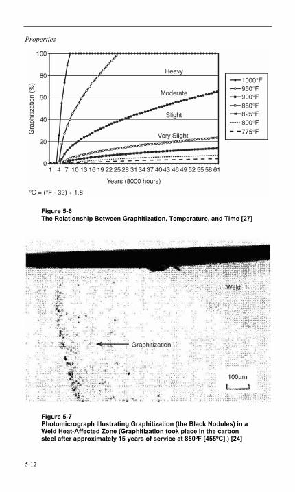
Properties
5-12
Figure 5-6 The Relationship Between Graphitization, Temperature, and Time [27]
Figure 5-7 Photomicrograph Illustrating Graphitization (the Black Nodules) in a Weld Heat-Affected Zone (Graphitization took place in the carbon steel after approximately 15 years of service at 850ºF [455ºC].) [24]
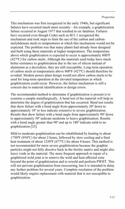
Properties
5-13
This mechanism was first recognized in the early 1940s, but significant failures have occurred much more recently—for example, a graphitization failure occurred in August 1977 that resulted in six fatalities. Failures have occurred even though Codes such as B31.1 recognized the mechanism and took steps to limit the use of the carbon and carbon-molybdenum steels to temperatures at which this mechanism would not be expected. The problem was that many plants had already been designed and built using these materials at higher temperatures. The temperature above which graphitization is expected to occur is approximately 800ºF (427ºC) for carbon steels. Although the materials used today have much better resistance to graphitization due to the use of silicon instead of aluminum as a deoxidizer, they are still susceptible. Long-term operation of carbon steels at temperatures above 800ºF (427ºC) should therefore be avoided. Modern power plant design would not allow carbon steels to be used for long-term operation at the elevated temperature at which graphitization could occur. However, the failure mechanism is still a concern due to material identification or design errors.
The recommended method to determine if graphitization is present is to examine a sample metallurgically. A bend test of the material will help to determine the degree of graphitization that has occurred. Bend test results that show failure with a bend angle from approximately 30º down to approximately 10º or less indicate extensive to severe graphitization. Results that show failure with a bend angle from approximately 90º down to approximately 30º indicate moderate to heavy graphitization. Results with a bend angle greater than 90º and up to 180º indicate mild to no graphitization [25].
Mild to moderate graphitization can be rehabilitated by heating to about 1750ºF (954ºC) for about 2 hours, followed by slow cooling and a final heat treatment of about 1250ºF (677ºC) for about 4 hours. This method is not recommended for more severe graphitization because the graphite particles might not fully dissolve back in the ferritic matrix and might also leave voids in the material. The more frequent approach to repair of a graphitized weld joint is to remove the weld and heat-affected zone beyond the point of graphitization and to reweld and perform PWHT. This will not prevent graphitization from reoccurring, but it is intended to delay any further problem for several years. Complete resolution of the problem would likely require replacement with material that is not susceptible to graphitization.
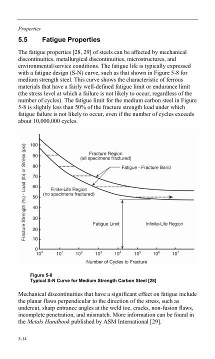
Properties
5-14
5.5 Fatigue Properties
The fatigue properties [28, 29] of steels can be affected by mechanical discontinuities, metallurgical discontinuities, microstructures, and environmental/service conditions. The fatigue life is typically expressed with a fatigue design (S-N) curve, such as that shown in Figure 5-8 for medium strength steel. This curve shows the characteristic of ferrous materials that have a fairly well-defined fatigue limit or endurance limit (the stress level at which a failure is not likely to occur, regardless of the number of cycles). The fatigue limit for the medium carbon steel in Figure 5-8 is slightly less than 50% of the fracture strength load under which fatigue failure is not likely to occur, even if the number of cycles exceeds about 10,000,000 cycles.
Figure 5-8 Typical S-N Curve for Medium Strength Carbon Steel [28]
Mechanical discontinuities that have a significant effect on fatigue include the planar flaws perpendicular to the direction of the stress, such as undercut, sharp entrance angles at the weld toe, cracks, non-fusion flaws, incomplete penetration, and mismatch. More information can be found in the Metals Handbook published by ASM International [29].
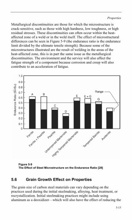
Properties
5-15
Metallurgical discontinuities are those for which the microstructure is crack-sensitive, such as those with high hardness, low toughness, or high residual stresses. These discontinuities can often occur within the heat-affected zone of a weld or in the weld itself. The effect of microstructural differences can be seen in Figure 5-9 (the endurance ratio is the endurance limit divided by the ultimate tensile strength). Because some of the microstructures illustrated are the result of welding in the areas of the heat-affected zone, this is in part the same issue as the metallurgical discontinuities. The environment and the service will also affect the fatigue strength of a component because corrosion and creep will also contribute to an acceleration of fatigue.
Figure 5-9 The Effect of Steel Microstructure on the Endurance Ratio [28]
5.6 Grain Growth Effect on Properties
The grain size of carbon steel materials can vary depending on the practices used during the initial steelmaking, alloying, heat treatment, or recrystallization. Initial steelmaking practices might include using aluminum as a deoxidizer—which will also have the effect of reducing the
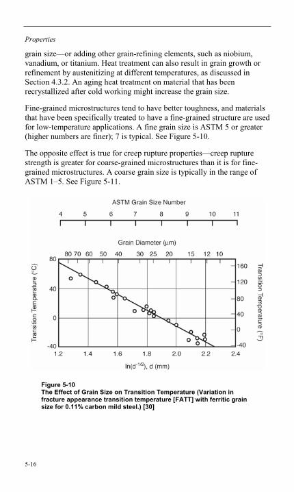
Properties
5-16
grain size—or adding other grain-refining elements, such as niobium, vanadium, or titanium. Heat treatment can also result in grain growth or refinement by austenitizing at different temperatures, as discussed in Section 4.3.2. An aging heat treatment on material that has been recrystallized after cold working might increase the grain size.
Fine-grained microstructures tend to have better toughness, and materials that have been specifically treated to have a fine-grained structure are used for low-temperature applications. A fine grain size is ASTM 5 or greater (higher numbers are finer); 7 is typical. See Figure 5-10.
The opposite effect is true for creep rupture properties—creep rupture strength is greater for coarse-grained microstructures than it is for fine-grained microstructures. A coarse grain size is typically in the range of ASTM 1–5. See Figure 5-11.
Figure 5-10 The Effect of Grain Size on Transition Temperature (Variation in fracture appearance transition temperature [FATT] with ferritic grain size for 0.11% carbon mild steel.) [30]
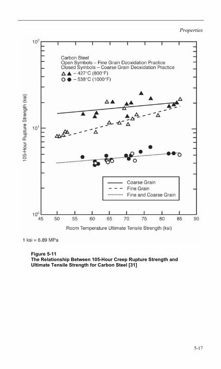
Properties
5-17
Figure 5-11 The Relationship Between 105-Hour Creep Rupture Strength and Ultimate Tensile Strength for Carbon Steel [31]

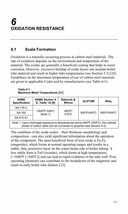
6-1
6 OXIDATION RESISTANCE
6.1 Scale Formation
Oxidation is a naturally occurring process in carbon steel materials. The rate of oxidation depends on the environment and temperature of the material. The oxides are generally a beneficial coating that helps to resist corrosion. However, excessive buildup of oxide layers can insulate boiler tube material and result in higher tube temperatures (see Section 5.3) [24]. Guidelines on the maximum temperature of use of carbon steel materials are given in applicable Codes and by manufacturers (see Table 6-1).
Table 6-1 Maximum Metal Temperatures [31]
ASME Specification
ASME Section II D, Table 1A [8]
Babcock & Wilcox ALSTOM Riley
SA-178 C
SA-192
SA-210 A1
1000ºF/ 538ºC (Note 1)
950ºF/ 510ºC 850ºF/454ºC 850ºF/454ºC
Note 1: Upon prolonged exposure to temperatures above 800ºF (454ºC), the carbide phase of carbon steel can be converted to graphite (see Section 5.4).
The condition of the oxide scales—their thickness morphology and composition—can also yield significant information about the operation of the component. The most beneficial form of iron oxide is Fe3O4 (magnetite), which forms at normal operating ranges and results in a stable, thin, protective layer on the water/steam side of boiler tubing. A less stable form is FeO (wustite), which forms at high temperatures (>1040ºF [>560ºC]) and can lead to rapid oxidation of the tube wall. Poor operating chemistry can contribute to the breakdown of the magnetite and result in early boiler tube failures [32].

Oxidation Resistance
6-2
6.2 Life Assessment by Oxide Thickness Measurement
Scale thickness measurements are widely used in life assessment of tubes in fossil fuel power plants. Exposure to this increased temperature can cause a rapid loss of tube life. A nondestructive measurement of the oxide scale thickness across the tube bank suggests whether a given tube has developed an excessive scale thickness. A greater-than-average scale thickness is taken as indicative of an excessively high temperature, which could deteriorate the remaining life of the particular tube and necessitate replacement of the tube bank. To correlate the thickness of the in-service oxide scale with the temperature history of a component, scale growth rate data are generated over a range of temperatures. For the purpose of life assessment, research groups that serve the power industry have also generated long-term scale growth data over an industrially relevant range of temperatures.
7-1
7 FABRICATION
7.1 Machinability
The carbon steels covered by this report have generally high levels of machinability [33, 34] even though this is not a factor for selection of the steel in the applications intended (primarily, power plant and pressure applications). Machinability can be based on tool life, cutting speed, power consumption, comparison with standard steels, quality of surface finish, and feeds resulting from constant thrust force [33]. As with other properties—such as strength, hardness, and ductility—carbon content is the dominant factor in machinability. Compared to a free-machining steel containing a high level of sulfur that would give the steel low weldability and a possible machinability rating of 100 (based on cutting speed), a carbon steel with approximately 0.15% carbon might have a machinability rating of 60. Carbon steel with 0.30% carbon might have a rating of 70. Steels with higher carbon contents, however, can result in lower ratings because the hardness of the material starts to reduce the machinability—carbon steel with 0.50% carbon might have a rating of only 45 [34].
7.2 Forming and Forging
Forming operations on carbon steels include any method of plastically deforming the material to achieve the desired component. Included are bending (both hot and cold), rolling, extrusion, drawing, and forging. Carbon steels are capable of being formed extensively due to the relatively high ductility of the material. Forming that is performed at temperatures lower than the transformation temperatures will result in cold strain, which can both increase the strength and reduce the ductility of the component, at times requiring a post-forming heat treatment to relieve stresses. Hot forming can affect the properties of the material and might require a heat treatment to recover those properties.
Forging is done with the steel in a high-temperature condition in the 2350–2400ºF (1290–1350ºC) range, with increasing forgeability as the forging rate increases. Generally, carbon steels can be forged very successfully; therefore, many carbon steel components are fabricated by
Fabrication
7-2
forging. Forging results in increased properties as a result of the fibrous grain structure that can enhance the properties in the high-stress direction. Forging can also heal porosity and reduce large as-cast grain sizes.
7.3 Welding
7.3.1 Weldability
Weldability is defined as “the capacity of a material to be welded under the imposed fabrication conditions into a specific, suitably designed structure and to perform satisfactorily in the intended service” [35]. Carbon steel is generally considered to be quite weldable, particularly when the carbon content is below 0.35%, which it is by specification in all of the materials covered in this report. A wide variety of processes are available to weld carbon steel satisfactorily, with properties and composition comparable in the weld and the base material.
The term weldability is also used in a narrower sense to mean the ease with which a material can be welded without cracking or other discontinuities. It is this meaning that is more relevant to the welding qualification.
P Number Designation Section IX of the ASME B&PV Code groups base metals with others of similar weldability. The materials covered in this report all have the current ASME Section IX designation of P number 1, with the exceptions listed in Table 7-1. The P number 1 materials are carbon or carbon-manganese steels. For the purpose of addressing toughness considerations, the P number 1 materials are subdivided into Groups 1–4. Although variations might be considered by the Section IX Code Committee, the following breakdown is used: • P number 1: Carbon or carbon-manganese steels
– Group 1: Minimum tensile strength of less than 70 ksi (485 MPa)
– Group 2: Minimum tensile strength of 70–80 ksi (485–550 MPa)
– Group 3: Minimum tensile strength of 80–90 ksi (550–620 MPa)
– Group 4: Minimum tensile strength of greater than 90 ksi (>620 MPa)
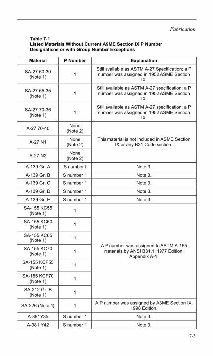
Fabrication
7-3
Table 7-1 Listed Materials Without Current ASME Section IX P Number Designations or with Group Number Exceptions
Material P Number Explanation
SA-27 60-30 (Note 1) 1
Still available as ASTM A-27 Specification; a P number was assigned in 1952 ASME Section
IX.
SA-27 65-35 (Note 1) 1
Still available as ASTM A-27 specification; a P number was assigned in 1952 ASME Section
IX.
SA-27 70-36 (Note 1) 1
Still available as ASTM A-27 specification; a P number was assigned in 1952 ASME Section
IX.
A-27 70-40 None (Note 2)
A-27 N1 None (Note 2)
A-27 N2 None (Note 2)
This material is not included in ASME Section IX or any B31 Code section.
A-139 Gr. A S number1 Note 3.
A-139 Gr. B S number 1 Note 3.
A-139 Gr. C S number 1 Note 3.
A-139 Gr. D S number 1 Note 3.
A-139 Gr. E S number 1 Note 3.
SA-155 KC55 (Note 1) 1
SA-155 KC60 (Note 1) 1
SA-155 KC65 (Note 1) 1
SA-155 KC70 (Note 1) 1
SA-155 KCF55 (Note 1) 1
SA-155 KCF70 (Note 1) 1
SA-212 Gr. B (Note 1) 1
A P number was assigned to ASTM A-155 materials by ANSI B31.1, 1977 Edition,
Appendix A-1.
SA-226 (Note 1) 1 A P number was assigned by ASME Section IX, 1998 Edition.
A-381Y35 S number 1 Note 3.
A-381 Y42 S number 1 Note 3.
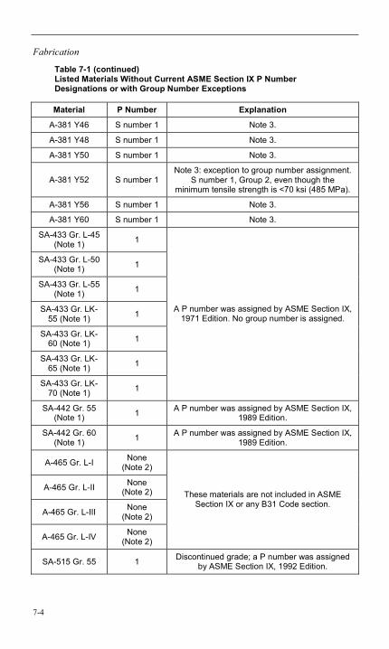
Fabrication
7-4
Table 7-1 (continued) Listed Materials Without Current ASME Section IX P Number Designations or with Group Number Exceptions
Material P Number Explanation
A-381 Y46 S number 1 Note 3.
A-381 Y48 S number 1 Note 3.
A-381 Y50 S number 1 Note 3.
A-381 Y52 S number 1 Note 3: exception to group number assignment.
S number 1, Group 2, even though the minimum tensile strength is <70 ksi (485 MPa).
A-381 Y56 S number 1 Note 3.
A-381 Y60 S number 1 Note 3.
SA-433 Gr. L-45 (Note 1) 1
SA-433 Gr. L-50 (Note 1) 1
SA-433 Gr. L-55 (Note 1) 1
SA-433 Gr. LK-55 (Note 1) 1
SA-433 Gr. LK-60 (Note 1) 1
SA-433 Gr. LK-65 (Note 1) 1
SA-433 Gr. LK-70 (Note 1) 1
A P number was assigned by ASME Section IX, 1971 Edition. No group number is assigned.
SA-442 Gr. 55 (Note 1) 1 A P number was assigned by ASME Section IX,
1989 Edition.
SA-442 Gr. 60 (Note 1) 1 A P number was assigned by ASME Section IX,
1989 Edition.
A-465 Gr. L-I None (Note 2)
A-465 Gr. L-II None (Note 2)
A-465 Gr. L-III None (Note 2)
A-465 Gr. L-IV None (Note 2)
These materials are not included in ASME Section IX or any B31 Code section.
SA-515 Gr. 55 1 Discontinued grade; a P number was assigned by ASME Section IX, 1992 Edition.
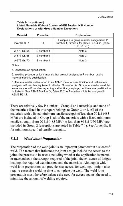
Fabrication
7-5
Table 7-1 (continued) Listed Materials Without Current ASME Section IX P Number Designations or with Group Number Exceptions
Material P Number Explanation
SA-537 Cl. 1 1 Exception to group number assignment: P
number 1, Group 2 for plate > 2.5–4 in. (63.5–101.6 mm).
A-573 Gr. 58 S number 1 Note 3.
A-573 Gr. 65 S number 1 Note 3.
A-573 Gr. 70 S number 1 Note 3.
Notes:
1. Discontinued specification.
2. Welding procedures for materials that are not assigned a P number require material-specific qualification.
3. The material is not included in an ASME material specification and is therefore assigned a P number equivalent called an S number. An S number can be used the same way as a P number regarding weldability groupings, but there are qualification limitations. See ASME Section IX, QW-420.2. A P number might be assigned in ASME B31.1.
There are relatively few P number 1 Group 3 or 4 materials, and none of the materials listed in this report belongs to Group 3 or 4. All of the materials with a listed minimum tensile strength of less than 70 ksi (485 MPa) are included in Group 1; all of the materials with a listed minimum tensile strength from 70 ksi (485 MPa) to less than 80 ksi (550 MPa) are included in Group 2 (exceptions are noted in Table 7-1). See Appendix B for minimum specified tensile strengths.
7.3.2 Weld Joint Preparation
The preparation of the weld joint is an important parameter in a successful weld. The factors that influence the joint design include the access to the joint, the process to be used (including whether the application is manual or mechanized), the strength required of the joint, the existence of fatigue loading, the required examination, and the materials. Although a wide weld joint preparation can provide easy access for welding, it might also require excessive welding time to complete the weld. The weld joint preparation must therefore balance the need for access against the need to minimize the amount of welding required.
Fabrication
7-6
Most applications in pressure-containing equipment require complete or mostly complete penetration welds so that the entire thickness of the joint is filled with sound weld metal. In many applications, this needs to be done from one side only because the root area of the joint might not be accessible after welding. In addition, filled welds are also expected to achieve essentially complete penetration into the root of the joint.
Some structural designs (and to a very limited extent, pressure designs) allow the use of partial penetration joints. The joint design in these cases must provide adequate access so that the required penetration can be achieved. When complete penetration welds are required, structural weld joints usually require either backing or welding from both sides.
The type of examination can also influence the joint design. For example, when an ultrasonic examination is required, the joint is prepared in a way that the backside of the weld minimizes the signal interruption by the joint configuration. Also, the use of backing rings can complicate the interpretation of radiographs.
The welding procedure specification (WPS) is required to specify the type of weld joint but might not always provide the detailed dimensions needed. Whether provided by the WPS or by other methods, the detailed dimensions are needed to provide the proper fit-up of the weld joint in preparation for welding. Due to welder preference, some variation in the fit-up requirements is required when the weld is to be done manually. Some typical weld joint designs are illustrated in Figures 7-1 through 7-3, although there are many variations possible that are not shown for special applications such as machine or automatic welding processes. Specific reference to ASME B16.5, Buttwelding Ends [36]; AWS D1.1, Structural Welding Code – Steel [37]; the welding procedure; and the Code being used for construction can provide additional direction.
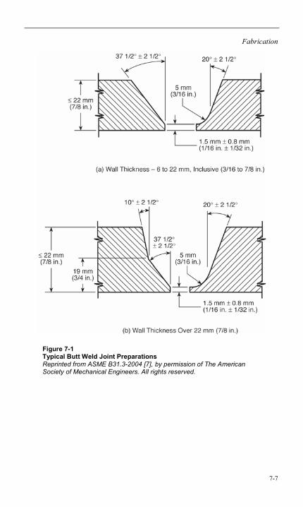
Fabrication
7-7
Figure 7-1 Typical Butt Weld Joint Preparations Reprinted from ASME B31.3-2004 [7], by permission of The American Society of Mechanical Engineers. All rights reserved.
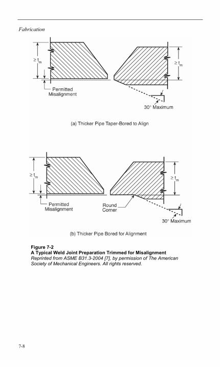
Fabrication
7-8
Figure 7-2 A Typical Weld Joint Preparation Trimmed for Misalignment Reprinted from ASME B31.3-2004 [7], by permission of The American Society of Mechanical Engineers. All rights reserved.
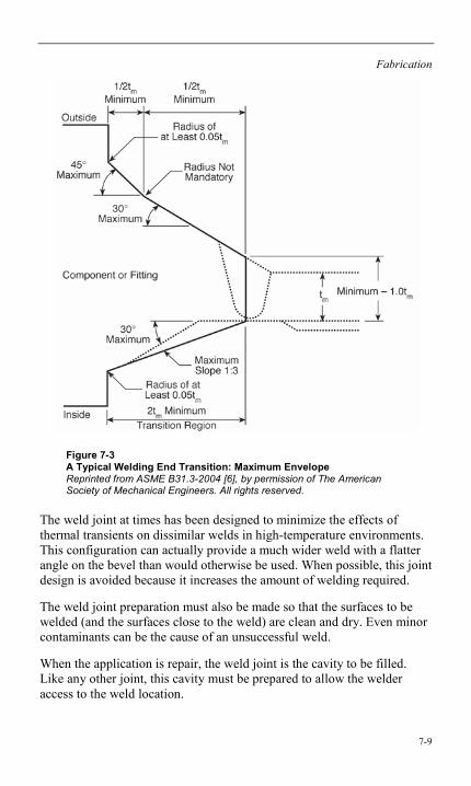
Fabrication
7-9
Figure 7-3 A Typical Welding End Transition: Maximum Envelope Reprinted from ASME B31.3-2004 [6], by permission of The American Society of Mechanical Engineers. All rights reserved.
The weld joint at times has been designed to minimize the effects of thermal transients on dissimilar welds in high-temperature environments. This configuration can actually provide a much wider weld with a flatter angle on the bevel than would otherwise be used. When possible, this joint design is avoided because it increases the amount of welding required.
The weld joint preparation must also be made so that the surfaces to be welded (and the surfaces close to the weld) are clean and dry. Even minor contaminants can be the cause of an unsuccessful weld.
When the application is repair, the weld joint is the cavity to be filled. Like any other joint, this cavity must be prepared to allow the welder access to the weld location.
Fabrication
7-10
7.3.3 WPSs
WPSs are required for all Code welding. When the fabrication is being done in accordance with ASME B&PV Code or ASME B31 Pressure Piping Codes, the WPSs that are required are those qualified in accordance with ASME Section IX, “Welding and Brazing Qualifications,” or those that are acceptable to the Section IX rules (specific rules are applicable in the case of standard welding procedures [SWPs] that have been accepted by ASME Section IX). These WPSs are intended to provide direction to the welder in order to make a weld that meets the design requirements for properties and soundness.
7.3.3.1 WPS Qualification
WPSs are generally required to be qualified by mechanical testing in accordance with ASME Section IX, “Welding and Brazing Qualifications,” in order to prove that welds using the WPS will provide the expected mechanical properties. A sample weld is typically subjected to tensile tests and bend tests (for groove welds) that verify that the weldment can achieve tensile and ductility properties similar to, but not less than, the base metals being tested. Additional tests might be required in cases for which impact toughness is required.
The American Welding Society (AWS) Structural Welding Code D1.1 [37] is often required for structures rather than the ASME B&PV or B31 Codes. The D1.1 code has its own rules for WPSs and the qualification of them. (It is possible that Section IX qualifications can be used in lieu of D1.1 qualifications. See the EPRI report Single Welding Qualification Code Project [38].)
The user is cautioned that the qualification rules for WPSs are simplified and apply to a broad range of materials (the P numbers described in Section 7.3.1). This can result in a WPS that is qualified but not technically adequate for welding some materials. For instance, a P number 1 carbon steel welding procedure qualified using 60-ksi (415-MPa) material and 60-ksi (415-MPa) filler metal could be considered to be qualified for P number 1 carbon steel material of 90 ksi (620 MPa) tensile strength using the same 60-ksi (415-MPa) filler metal. This presents the problem that the weldment might not meet the strength requirements of the base metal. Some (but not all) Codes require that the WPS qualification be performed using materials of the maximum strength level to be used or that the filler metal selected be of similar strength and chemical composition as the base metal. In this latter case, the designer can select other filler metals.
Fabrication
7-11
7.3.3.2 Selection of a Welding Procedure
The WPS selection is based on several factors. All of the requirements of the Code used for the construction, fabrication, or repair must be followed to comply with those rules. These requirements include preheat heat treatment and PWHT for the weldment as well as any specific requirements that affect the qualification of the WPS. Therefore, any WPS to be used must at a minimum be qualified to meet those requirements. The WPS must also be qualified for the base metals to be welded (P number 1 materials for the materials in this report) and for the welding process. The welding process to be used is generally chosen on the basis of quality requirements, access, production, and the availability of personnel qualified to use the WPS.
7.3.3.3 Welding Techniques
Carbon steels are relatively insensitive to the techniques used during welding (in comparison to alloy steels). This is due to the relatively low hardenability of this class of material. However, because a relatively high carbon content does exist in carbon steels as compared to alloyed steels, high hardnesses can be created by welding. Normally, multiple pass welds will temper the previous passes to some extent, but this will not occur with a single pass weld or with the last pass. As a result, single pass welds should be used with caution, and the last pass should probably be on the cap of the weld rather than at the toe. (This would not be particularly important if the weld were required to undergo PWHT.)
This leads to the possible use of controlled deposition techniques in order to avoid the need to do PWHT. The typical controlled deposition techniques are half bead and temper bead techniques. Half bead techniques reduce each pass by grinding to allow a subsequent pass to effectively temper the previous weld and heat-affected zone. Temper bead techniques do the same thing by controlling not only the placement of each weld bead but also the relative heat input of the weld so that the same tempering effect occurs. These techniques might not reduce the residual stresses in the weldment by much, but the hardness and the toughness of the weld will be enhanced, possibly with better properties than a similar weld after PWHT.
Fabrication
7-12
7.3.4 Welder and Welding Operator Qualification
The intent of the performance qualification of welding personnel is to verify that the welder or welding operator is capable of producing a sound weld using a qualified WPS. The variables established by ASME Section IX and by AWS D1.1 for welder qualification can make the welding more difficult. Both Section IX and D1.1 have specific welder and welding operator qualification rules, but like the WPS qualification, it is possible to apply Section IX qualifications to D1.1 [38].
Regarding personnel qualification, it is very important that personnel maintain the validity of their qualifications. The welder must maintain his or her qualification; for example, a welder must perform welding no less than once every six months. Perhaps even more important is to be aware that there are many influences that can prevent a qualified welder from making sound welds, including physical and mental barriers and access issues. When there is a reason to question the ability of the welder to make a weld that is sound and in accordance with the WPS, the qualification should be reviewed to determine if additional steps should be taken. This is a requirement of the Codes that cover welding qualification (for example, Section IX, QW-322).
7.3.5 Preheat and PWHT
7.3.5.1 Preheat
The primary purpose of preheat prior to and during welding is to slow the cooling rate in the weld area. This has multiple effects on the resulting weldment. For those materials that have a high hardenability, the effect is to lower the hardness levels that result from the extreme thermal cycles that occur during welding. For carbon steel materials of fairly high relative carbon content, this becomes important—particularly for single pass welds because these will result in very high peak hardnesses that are not somewhat tempered by other passes.
The objective in lowering the hardness is to minimize the crack sensitivity in the heat-affected zone where the highest hardnesses often occur. These high local hardnesses, particularly adjacent to the weld fusion line, contribute to local material differences that can contribute to fatigue cracking. High hardness levels also increase the susceptibility to corrosion. Finally, the high local hardnesses, coincident with the existence of diffusible hydrogen being rejected from the molten weld metal, can also contribute to hydrogen cracking.
Fabrication
7-13
The hydrogen cracking mechanism is not common in most carbon steels belonging to the P number 1 Groups 1 and 2 covered by this report, although it can occur if normal precautions are not taken. Normal precautions include the preheat required or recommended by the Codes, the care of electrodes and fluxes to minimize the moisture content, and the normal use of multiple pass welds.
The cooling rates that occur during welding are a result of multiple factors beyond the use of preheat. Included are factors such as material thickness (because the primary heat removal is by conduction), thermal conductivity, and welding heat input. Preheat might be needed to counteract such factors. With the exception of the material thicknesses, the rules contained in the Codes do not directly address these factors.
The current Code (B&PV and B31) rules for preheat of carbon steels are fairly consistent. The general requirements are as follow: the minimum preheat is 50ºF (10ºC), and for materials with a carbon content > 0.30% and a thickness at the joint > 1 in. (25 mm), the minimum preheat is 175ºF (80ºC).
Specific preheat rules follow:
• B31.1 – Mandatory.
• B31.3 [7] – Recommended. Uses a tensile strength criteria (> 71 ksi [490MPa]) in lieu of a carbon content criteria.
• Section I [39] – Recommended.
• Section III [40] – Recommended. Appendix D suggests an upper preheat temperature minimum of 250ºF (120ºC).
• Section VIII [41] – Recommended.
Consideration of preheat beyond the requirements of the Codes might be necessary under some circumstances, such as when there is a significant concern for hydrogen cracking. The AWS D1.1 Code [37], Annex XI, “Guidelines on Alternative Methods for Determining Preheat,” provides some criteria for making these decisions. There are also Code requirements for preheat under conditions for which an otherwise required PWHT can be exempted.
There are some restrictions within ASME Section IX qualified WPSs on changes in the preheat being applied. These include a reduction in preheat from that which was qualified (a reduction > 100ºF [55ºC]) or, when impact toughness testing is required, an increase in the interpass
Fabrication
7-14
temperature from that qualified (an increase > 100ºF [55ºC]). It is necessary to observe the preheat requirements of the WPS being used as well as the Code requirements and recommendations.
Preheating the weld joint is done through a variety of methods. Smaller joints can be adequately preheated with a heating torch, although care is required to avoid large temperature differences and contamination of the weld joint. Alternatively, the weld joint area can be preheated using electrical resistance pads or induction heating coils. Both are effective in maintaining a consistent and controllable preheat temperature. The temperature of the preheated joint can be measured with temperature-indicating crayons (avoid using directly in the area to be welded), pyrometers, thermocouples (with readout equipment), and even infrared devices. The objective is to reach the required temperature prior to starting any welding. It is recommended that the area to be preheated extend beyond the weld joint by at least 1 in. (25 mm).
Related to preheating, the control of interpass temperatures can be required, although this is not generally a requirement for carbon steels. If required, interpass temperature is usually expressed as a maximum (the preheat is the minimum) prior to welding. Again, the same methods can be used to determine the temperature, but the measurement is taken during welding or between weld passes.
7.3.5.2 PWHT
The primary reasons that components are required to be subjected to PWHT within the ASME Code rules are that PWHT reduces residual stresses and tempers hardened microstructures [42]. PWHT will achieve both of these results but might not positively benefit the overall properties of the weldment if not properly controlled, particularly in terms of the toughness in the heat-affected zone. When toughness is a requirement, the Codes will impose additional controls on the PWHT, such as time at temperature controls. PWHT done to meet the Code requirements is typically performed at subcritical temperatures (see Section 4.3).
Residual stresses can contribute to increases in the susceptibilty to corrosion mechanisms and to fatigue. Because residual stresses cannot exceed the yield strength of the materials, an immediate benefit of increasing the temperature of the material during PWHT is a corresponding drop in the yield strength of the material and thus a reduction of the maximum residual stresses in the weldment. In order to further reduce the residual stresses, the weldment will need to be held for
Fabrication
7-15
longer periods at the elevated temperatures (this reduction occurs by relaxation-recrystallization or primary creep mechanisms). Although the reduction of residual stresses is a benefit of PWHT, most of the rules for PWHT specified in the Codes are targeted at the hardened microstructures. This is because the applications that might require a reduction in residual stresses are not addressed specifically in the Codes.
Post-weld treatment acts as a tempering process by reducing the hardness of the heat-affected zone and the weld metal. Tempering is a heat treatment whereby the material is heated to a temperature below the lower critical temperature (often assumed to be approximately 1340ºF [725ºC] for carbon steels). The PWHT for carbon steels is generally done in the range of 1100–1200ºF (600–650ºC), although some Codes specify only the minimum temperature of 1100ºF (600ºC). A secondary effect of tempering is to allow some additional transformation of the martensitic grain structure into ferrite, but the main objective is tempering the martensite. The result can be increased ductility and toughness in addition to reduced hardness. If the tempering temperature is too high or held too long, some corresponding reduction in the toughness can result.
The Code requirements for PWHT of carbon steels are quite inconsistent. They are, however, mandatory within each Code application. The thicknesses that require PWHT vary from 0.75 in. (19.1 mm) for the greater thickness at the joint to 1.5 in. (38.1 mm) for the thinner thickness at the joint. There are also many exemptions that apply to different types of welds and for welds in which the weld thickness is less than the exemption thickness. There are efforts to try to bring more consistency to the various Codes, and changes are likely. The one value that is reasonably consistent for carbon steels is the holding temperature previously described. In addition to the Code requirements describing the PWHTs, the WPSs also contain the requirements for PWHT. Both the Code requirement and the WPS requirement must be followed.
Although not normally considered during construction, there can also be requirements for PWHT at temperatures greater than the lower critical temperatures, most likely a heat treatment that will be greater than the upper critical temperature such that the affected material will be austenitized prior to cooling. These heat treatments can be normalizing, annealing, or quenching. In the case of the quenching heat treatment, a subcritical tempering heat treatment would likely follow for carbon steels. The purpose of these heat treatments is to affect the properties of the material and to remove the metallurgical inconsistencies that result from welding. These types of heat treatments are often not required on carbon steel until high strength properties are required.
Fabrication
7-16
PWHT can be accomplished either in a furnace in a shop setting or locally in a field setting. Shop furnaces can be quite large and might include an entire large component. They can be gas fired or electric resistance heated. Care is necessary when using this type of heat treatment equipment: the furnace temperatures must be evenly controlled and the loading balanced.
The heating and cooling rates are required by the Codes to be controlled at maximum rates of either 400ºF (220ºC) per hour or 600ºF (335ºC) per hour, normally above 600ºF (315ºC) to the holding temperature. The purpose of this is to minimize distortion and stresses developed by high thermal gradients.
Local PWHT is often the only choice in field applications. For large vessels, this can be an extensive undertaking because it normally requires the entire circumference of the vessel to be subjected to the PWHT even if the welding occurred at a limited area. ASME Section VIII does allow local PWHT without heating the entire circumference in some applications (see Section VIII, Div. 1, paragraph UW-40 [41]). Local PWHT requires that the soak band (the heated material that is held at the required PWHT temperature) extend beyond the edges of the weld usually by at least one thickness at the joint or a thickness that is three times the total width. The purpose of this width is to ensure that the inner diameter of the weld has been adequately heat-treated because the heated band will be much narrower at the inner diameter when it is uninsulated and the only heating occurs on the outer diameter.
Local PWHT might require multiple controlled zones as a result of heat losses that are not equal at all points (for example, the top and bottom of heated areas, unequal thicknesses, and so forth). In order to properly control the PWHT zone or zones, it is necessary to install thermocouples not only on the weld but also at the limits of the soak band. Excellent suggestions for this are available in AWS’s publication Recommended Practices for Local Heating of Welds in Piping and Tubing [43].
Care must be exercised to ensure that the components are supported during PWHT because the strength of the materials at the high temperatures can be significantly lower. It is also necessary to protect or remove materials that cannot tolerate the high PWHT temperatures (such as valve packing and instruments).
Fabrication
7-17
7.3.6 Filler Metal Selection
An ideal weld would be one that is invisible to the environment and the loads imposed on it. This means that in the ideal weld, the weld metal and the heat-affected zone are very similar in chemical composition and strength properties to those of the base metals being welded. Obviously, this is not always possible due to factors such as dissimilar joints, the availability of filler metals that will result in a deposit of a similar composition, certain weld designs that require different strength properties, the inability to duplicate manufacturing heat treatments, and the inherent isotropy of the dendritic weld structure. However, when these factors are not controlling, the choice of filler metals should achieve as much similarity as possible. In carbon steels, this is primarily achieved by selecting filler metals whose deposit strength is not significantly less or more than the base materials being welded.
As with all of the variables associated with welding, the choice of filler metals is controlled by the WPS and what was used during the WPS qualification. However, particularly for the carbon steels, there can be an excessive range of qualified filler as a result of one qualification test. For example, procedure qualification using a low tensile strength P number 1 carbon steel base material and low tensile strength filler would serve to qualify a much higher tensile strength P number 1 base material with the same low tensile strength filler. This would obviously violate the intent to achieve similar strength properties in the weld and the base material. Some Codes have rules that would require the qualification of the highest strength base materials to be used or to use filler metals of similar strength as the base material.
For the materials in this report, the typical filler metals can be those types designated as E60xx or E70xx for shielded metal arc welding (SMAW), ER70S-x for gas tungsten arc welding (GTAW) or gas metal arc welding (GMAW), and E6xT-x or E7xT-x for flux-cored arc welding (FCAW). The choice of filler metal for the submerged arc welding (SAW) process is more complicated because it involves both the electrode selection and the flux selection. The filler metal specifications (AWS [44] and ASME [45]) for these materials are as follows:
• SMAW: AWS A-5.1 or ASME SFA-5.1
• GTAW or GMAW: AWS A-5.18 or ASME SFA-5.18
• FCAW: AWS A-5.20 or ASME SFA-5.20
• SAW: AWS A-5.17 or SFA-5.17
Fabrication
7-18
Although carbon steels are not as susceptible to hydrogen cracking as the alloy steel materials, it is advisable to use electrodes that have low diffusible hydrogen content of H8 or less.
7.4 Repair
Repair can take the form of restoring the item to the original configuration by a total replacement of sections or components. Repair sometimes takes the form of techniques in which there is a new configuration but the resulting repair will serve the need. In some cases, the repair is not expected to be permanent but rather a stop-gap measure to gain time until a permanent repair can be made. Repair of a component or section requires some knowledge of the expected cause of the failure or degradation in order to avoid a repeat failure or to avoid exacerbating the cause. However, in the case of a temporary repair, often the true cause can not be resolved, but the prior history allows temporary operation in order to properly prepare for a permanent repair.
Repairs in power plants are usually accomplished by welding in new sections or components or reinforcing the failed or degraded area with weld metal. In some cases, rather than to strictly provide strength, the weld metal is added to provide corrosion resistance or a hard, wear-resistant surface. When the pressure boundary is not violated, there might even be occasions when the repair can be done during operation.
Modern repair techniques have been developed for specific problems, often supported by EPRI. Significant work has gone into the acceptance of weld repair on heavy section components and low alloys using the temper bead techniques in order to avoid PWHT. The National Board Inspection Code (NBIC) [46] specifically outlines temper bead and similar controlled deposition techniques for repair welding without PWHT. EPRI has sponsored extensive testing of temper bead welds in support of this method. ASME Section IX [9] has also incorporated qualification rules for temper bead welding procedures.
A number of organizations are providing some direction on repairs. Section XI, “Rules for Inservice Inspection of Nuclear Power Plant Components [47],” includes a number of acceptable repair methods, and ASME has also issued a number of Code cases that address different repair methods. ASME B31.1 [6] contains a nonmandatory Appendix V, “Recommended Practice for Operation, Maintenance, and Modification for Power Piping Systems.” The NBIC also allows the repair buildup of wasted areas and the installation of certain types of patches by welding.
Fabrication
7-19
The ASME Post Construction Committee is generating guides on repair techniques (not yet published as of this writing). The American Petroleum Institute (API) publishes API 510, Pressure Vessel Inspection Code: Maintenance Inspection, Rating, Repair and Alteration [48] and API 570, Piping Inspection Code: Inspection, Repair, Alteration, and Rerating of In-Service Piping Systems [49]. It is not possible to include all of the directions contained in these and other documents on repair methods; it is left to the user to identify specific approaches to satisfy the user’s needs.
7.5 Welding Dissimilar Steels
Steels of many different compositions or properties are often required to be joined to the carbon steels covered in this report. The change in composition might be for a wide variety of reasons, including changes in the temperature of operation, corrosion problems (particularly flow-assisted corrosion), and transitions between components (such as valves to pipe, pumps to pipe, and so on). When welding carbon steels to low-alloy steels, a slight preference would be to use filler metals similar in composition to the alloy material or to some intermediate composition. However, the practice of using fillers similar to the carbon steel material has also been used.
When the weld is between carbon steel and austenitic stainless steel, a filler with increased chromium and nickel content, such as a Type 309 alloy, is often used. This increased alloy content will help to form a similar composition in the weld when diluted with the carbon steel base material. Nickel-based fillers are also used—particularly in high-temperature applications—because the nickel-based material has a thermal expansion coefficient that is closer to the carbon steel than the austenitic filler.
Other techniques are used to provide for transitions between dissimilar metals. One technique is to “butter” the end of the carbon steel with a transition material. This is done by weld depositing a surface layer on the carbon steel joint and then preparing it for welding to the alloy or the stainless material. This technique is often used to avoid the requirement to perform PWHT on the final weld because the “buttered” surface can receive the PWHT required for the carbon steel, eliminating the need to perform PWHT on the final joint.

8-1
8 REFERENCES
1. ASME Boiler and Pressure Vessel Code, various editions. American Society of Mechanical Engineers, New York.
2. J. E. Bringas, Handbook of Comparative World Steel Standards, 2nd Edition. ASTM DS67A. ASTM International, West Conshohocken, PA: 2002.
3. Metals and Alloys in the Unified Numbering System. SAE HS-1086/ASTM DS-56, various editions. SAE International, Warrendale, PA and ASTM International, Conshohocken, PA.
4. Pressure Piping. ASME B31. American Society of Mechanical Engineers, New York: 2004.
5. ASME Boiler and Pressure Vessel Code, Section II, Part A, “Properties.” American Society of Mechanical Engineers, New York: 2004 with 2005 Addenda.
6. Power Piping. ASME B31.1. American Society of Mechanical Engineers, New York: 2004.
7. Process Piping. ASME B31.3. American Society of Mechanical Engineers, New York: 2004.
8. ASME Boiler and Pressure Vessel Code, Section II, Part D, “Ferrous Material Specifications.” American Society of Mechanical Engineers, New York: 2004 with 2005 Addenda.
9. ASME Boiler and Pressure Vessel Code, Section IX, “Welding and Brazing Qualification.” American Society of Mechanical Engineers, New York: 2004 with 2005 Addenda.
10. Realistic Carbon Equivalent for Underwater Welding. EPRI, Palo Alto, CA: 2002. 1006799.
11. G. E. Linnert, Welding Metallurgy: Fundamentals, 4th Edition, Volume 1. American Welding Society, Miami, FL: 1994.
12. Metals Handbook, Volume 9: Metallography and Microstructures, “Metallurgy and Microstructure,” “Bainitic Structures.” ASM International, Materials Park, OH: 2004.
References
8-2
13. Metallurgical Guidebook for Fossil Power Plant Boilers. EPRI, Palo Alto, CA: 2006. 1011912.
14. Metals Handbook, Volume 4: Heat Treating, “Heat Treating of Steel,” “Quantitative Prediction of Transformation Hardening in Steels,” “Relationship Between IT, CCT, and Jominy Curves.” ASM International, Materials Park, OH: 2002.
15. United States Steel, I-T Diagrams, 1963.
16. ASME Boiler and Pressure Vessel Code, Section II, Part A, Ferrous Material Specifications, SA-941, “Specification for Terminology Relating to Steel, Stainless Steel, Related Alloys, and Ferroalloys.” American Society of Mechanical Engineers, New York: 2004.
17. Metals Handbook, Volume 1, Properties and Selection: Irons, Steels, and High Performance Alloys, “Carbon and Low Alloy Steels,” “Physical Properties of Carbon and Low Alloy Steels.” ASM International, Materials Park, OH: 2002.
18. “General Properties of Steels.” Retrieved from www.eFunda.com, 2006.
19. The Grade 22 Low Alloy Steel Handbook. EPRI, Palo Alto, CA: 2005. 1012840.
20. Metals Handbook, Desk Edition, “Glossary of Terms.” ASM International, Materials Park, OH: 2002.
21. Metals Handbook, Volume 11: Failure Analysis and Prevention, “Fracture,” “Creep and Stress Rupture Failures,” “Bulk Creep Behavior.” ASM International, Materials Park, OH: 2003.
22. Boiler Tube Failure Metallurgical Guide, Volume 2: Appendices. EPRI, Palo Alto, CA: 1994. TR-102433-V2.
23. G. V. Smith, An Evaluation of the Elevated Temperature Tensile and Creep-Rupture Properties of Wrought Carbon Steel. ASTM Data Series DS 11S1. ASTM International, West Conshohocken, PA: 1970.
24. Boiler Tube Failures: Theory and Practice, Volume 3: Steam-Touched Tubes. EPRI, Palo Alto, CA: 1996. TR-105261-V3.
References
8-3
25. Metals Handbook, Volume 1: Properties and Selection: Irons, Steels, and High Performance Alloys, “Service Characteristics of Carbon and Low-Alloy Steels,” “Elevated Temperature Properties of Ferritic Steels,” “Factors Affecting Mechanical Properties.” ASM International, Materials Park, OH: 2002.
26. H. Thielsch, “Material Selection,” Defects and Failures in Pressure Vessels and Piping. Reinhold Publishing, New York: 1965.
27. P. Duebler, personal correspondence related to B31.1 Code Revision, 2005.
28. Atlas of Fatigue Curves. ASM International, Materials Park, OH: 1986.
29. Metals Handbook, Volume 19: Fatigue and Fracture, “Fracture Mechanics, Damage Tolerance, and Life Assessment,” “Fatigue and Fracture Control of Weldments,” “Fatigue in Welded Joints.” ASM International, Materials Park, OH: 2002.
30. Metals Handbook, Desk Edition, “Service Characteristics of Carbon and Low Alloy Steels,” “Notch Toughness of Steels, Effects of Manufacturing Practices.” ASM International, Materials Park, OH: 2002.
31. M. K. Booker and B. L. P. Booker, “Factors Influencing the Time-Dependent Properties of Carbon Steels for Elevated Temperature Pressure Vessels,” Analysis of Elevated Temperature Tensile and Creep Properties of Wrought Carbon Steels, MPC-Volume 19. American Society of Mechanical Engineers, New York: 1983.
32. Boiler Tube Failures: Theory and Practice, Volume 1, Boiler Tube Fundamentals. EPRI, Palo Alto, CA: 1996. TR-105261-V1.
33. Metals Handbook, Volume 1, Properties and Selection: Irons, Steels, and High Performance Alloys, “Fabrication Characteristics of Carbon and Low Alloy Steels,” “Machinability of Steels,” “Machinability Ratings of Steels.” ASM International, Materials Park, OH: 2002.
34. Metals Handbook, Volume 1, Properties and Selection: Irons, Steels, and High Performance Alloys, “Fabrication Characteristics of Carbon and Low Alloy Steels,” “Machinability of Steels,”” Carbon Steels.” ASM International, Materials Park, OH: 2002.
35. R. D. Stout, Weldability of Steels. Welding Research Council, 1987.
References
8-4
36. Buttwelding Ends. ASME B16.25. American Society of Mechanical Engineers, New York: 2003.
37. Structural Welding Code – Steel. D1.1/D1.1M. American Welding Society, Miami, FL: 2004.
38. Single Welding Qualification Code Project. EPRI, Palo Alto, CA: 2004. 1009714.
39. ASME Boiler and Pressure Vessel Code, Section I, “Power Boilers.” American Society of Mechanical Engineers, New York: 2004 with 2005 Addenda.
40. ASME Boiler and Pressure Vessel Code, Section III, “Nuclear Power Plant Components.” American Society of Mechanical Engineers, New York: 2004 with 2005 Addenda.
41. ASME, Boiler and Pressure Vessel Code, Section VIII, Division 1, “Rules for Construction of Pressure Vessels.” American Society of Mechanical Engineers, New York: 2004 with 2005 Addenda.
42. BPTCS Task Group on PWHT – Final Report. American Society of Mechanical Engineers, New York: 1998.
43. Recommended Practices for Local Heating of Welds in Piping and Tubing. D10.10/ D10.10M. American Welding Society, Miami, FL: 1999.
44. Filler Metal Specifications. A5.xx. American Welding Society, Miami, FL: various dates.
45. ASME Boiler and Pressure Vessel Code, Section II, Part C, “Specifications for Welding Rods, Electrodes, and Filler Metals.” American Society of Mechanical Engineers, New York: 2004 with 2005 Addenda.
46. National Board Inspection Code. NB-23. National Board of Boiler and Pressure Vessel Inspectors, Columbus, OH: 2001.
47. ASME Boiler and Pressure Vessel Code, Section XI, “Rules for Inservice Inspection of Nuclear Power Plant Components.” American Society of Mechanical Engineers, New York: 2004 with 2005 Addenda.
48. Pressure Vessel Inspection Code: Maintenance Inspection, Rating, Repair and Alteration, API 510. API, Washington, D.C.: 2003.

References
8-5
49. Piping Inspection Code: Inspection, Repair, Alteration, and Rerating of In-Service Piping Systems. API 570. API, Washington, D.C.: 2003.

A-1
A CHEMICAL COMPOSITIONS OF SELECTED CARBON STEELS
Including a list of materials covered.
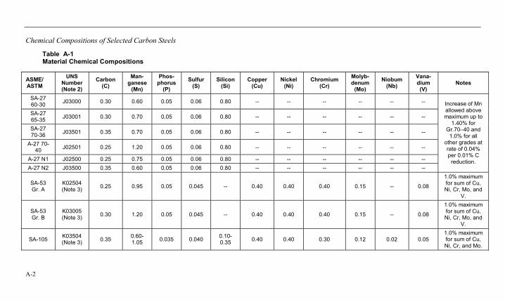
Chemical Compositions of Selected Carbon Steels
A-2
Table A-1 Material Chemical Compositions
ASME/ ASTM
UNS Number (Note 2)
Carbon (C)
Man-ganese
(Mn)
Phos-phorus
(P)
Sulfur (S)
Silicon (Si)
Copper (Cu)
Nickel (Ni)
Chromium (Cr)
Molyb-denum
(Mo)
Niobum (Nb)
Vana-dium (V)
Notes
SA-27 60-30 J03000 0.30 0.60 0.05 0.06 0.80 -- -- -- -- -- --
SA-27 65-35 J03001 0.30 0.70 0.05 0.06 0.80 -- -- -- -- -- --
SA-27 70-36 J03501 0.35 0.70 0.05 0.06 0.80 -- -- -- -- -- --
A-27 70-40 J02501 0.25 1.20 0.05 0.06 0.80 -- -- -- -- -- --
A-27 N1 J02500 0.25 0.75 0.05 0.06 0.80 -- -- -- -- -- -- A-27 N2 J03500 0.35 0.60 0.05 0.06 0.80 -- -- -- -- -- --
Increase of Mn allowed above maximum up to
1.40% for Gr.70–40 and
1.0% for all other grades at rate of 0.04% per 0.01% C
reduction.
SA-53 Gr. A
K02504 (Note 3) 0.25 0.95 0.05 0.045 -- 0.40 0.40 0.40 0.15 -- 0.08
1.0% maximum for sum of Cu, Ni, Cr, Mo, and
V.
SA-53 Gr. B
K03005 (Note 3) 0.30 1.20 0.05 0.045 -- 0.40 0.40 0.40 0.15 -- 0.08
1.0% maximum for sum of Cu, Ni, Cr, Mo, and
V.
SA-105 K03504 (Note 3) 0.35 0.60-
1.05 0.035 0.040 0.10-0.35 0.40 0.40 0.30 0.12 0.02 0.05
1.0% maximum for sum of Cu, Ni, Cr, and Mo.
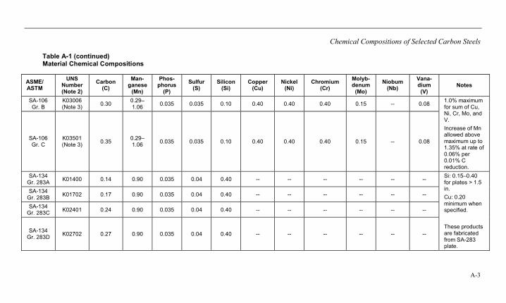
Chemical Compositions of Selected Carbon Steels
A-3
Table A-1 (continued) Material Chemical Compositions
ASME/ ASTM
UNS Number (Note 2)
Carbon (C)
Man-ganese
(Mn)
Phos-phorus
(P)
Sulfur (S)
Silicon (Si)
Copper (Cu)
Nickel (Ni)
Chromium (Cr)
Molyb-denum
(Mo)
Niobum (Nb)
Vana-dium (V)
Notes
SA-106 Gr. B
K03006 (Note 3) 0.30 0.29–
1.06 0.035 0.035 0.10 0.40 0.40 0.40 0.15 -- 0.08
SA-106 Gr. C
K03501 (Note 3) 0.35 0.29–
1.06 0.035 0.035 0.10 0.40 0.40 0.40 0.15 -- 0.08
1.0% maximum for sum of Cu, Ni, Cr, Mo, and V. Increase of Mn allowed above maximum up to 1.35% at rate of 0.06% per 0.01% C reduction.
SA-134 Gr. 283A K01400 0.14 0.90 0.035 0.04 0.40 -- -- -- -- -- --
SA-134 Gr. 283B K01702 0.17 0.90 0.035 0.04 0.40 -- -- -- -- -- --
SA-134 Gr. 283C K02401 0.24 0.90 0.035 0.04 0.40 -- -- -- -- -- --
SA-134 Gr. 283D K02702 0.27 0.90 0.035 0.04 0.40 -- -- -- -- -- --
Si: 0.15–0.40 for plates > 1.5 in. Cu: 0.20 minimum when specified. These products are fabricated from SA-283 plate.
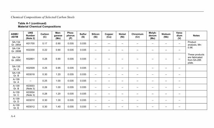
Chemical Compositions of Selected Carbon Steels
A-4
Table A-1 (continued) Material Chemical Compositions
ASME/ ASTM
UNS Number (Note 2)
Carbon (C)
Man-ganese
(Mn)
Phos-phorus
(P)
Sulfur (S)
Silicon (Si)
Copper (Cu)
Nickel (Ni)
Chromium (Cr)
Molyb-denum
(Mo)
Niobum (Nb)
Vana-dium (V)
Notes
SA-134 Gr. 285A K01700 0.17 0.90 0.035 0.035 -- --- -- -- -- -- --
SA-134 Gr. 285B K02200 0.22 0.90 0.035 0.035 -- -- -- -- -- -- --
SA-134 Gr. 285C K02801 0.28 0.90 0.035 0.035 -- -- -- -- -- -- --
Product analysis, Mn: 0.98. These products are fabricated from SA-285 plate.
SA-135 Gr. A K02509 0.25 0.95 0.035 0.035 -- -- -- -- -- -- --
SA-135 Gr. B K03018 0.30 1.20 0.035 0.035 -- -- -- -- -- -- --
A-139 Gr. A -- 0.25 1.00 0.035 0.035 -- -- -- -- -- -- --
A-139 Gr. B
K03003 (Note 3) 0.26 1.00 0.035 0.035 -- -- -- -- -- -- --
A-139 Gr. C
K03004 (Note 3) 0.28 1.20 0.035 0.035 -- -- -- -- -- -- --
A-139 Gr. D K03010 0.30 1.30 0.035 0.035 -- -- -- -- -- -- --
A-139 Gr. E K03012 0.30 1.40 0.035 0.035 -- -- -- -- -- -- --
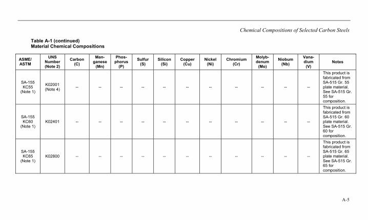
Chemical Compositions of Selected Carbon Steels
A-5
Table A-1 (continued) Material Chemical Compositions
ASME/ ASTM
UNS Number (Note 2)
Carbon (C)
Man-ganese
(Mn)
Phos-phorus
(P)
Sulfur (S)
Silicon (Si)
Copper (Cu)
Nickel (Ni)
Chromium (Cr)
Molyb-denum
(Mo)
Niobum (Nb)
Vana-dium (V)
Notes
SA-155 KC55
(Note 1)
K02001 (Note 4) -- -- -- -- -- -- -- -- -- -- --
This product is fabricated from SA-515 Gr. 55 plate material. See SA-515 Gr. 55 for composition.
SA-155 KC60
(Note 1) K02401 -- -- -- -- -- -- -- -- -- -- --
This product is fabricated from SA-515 Gr. 60 plate material. See SA-515 Gr. 60 for composition.
SA-155 KC65
(Note 1) K02800 -- -- -- -- -- -- -- -- -- -- --
This product is fabricated from SA-515 Gr. 65 plate material. See SA-515 Gr. 65 for composition.

Chemical Compositions of Selected Carbon Steels
A-6
Table A-1 (continued) Material Chemical Compositions
ASME/ ASTM
UNS Number (Note 2)
Carbon (C)
Man-ganese
(Mn)
Phos-phorus
(P)
Sulfur (S)
Silicon (Si)
Copper (Cu)
Nickel (Ni)
Chromium (Cr)
Molyb-denum
(Mo)
Niobum (Nb)
Vana-dium (V) Notes
SA-155 KC70
(Note 1) K03101 -- -- -- -- -- -- -- -- -- -- --
This product is fabricated from SA-515 Gr. 70 plate material. See SA-515 Gr. 70 for composition.
SA-155 KCF55 (Note 1)
K01800 -- -- -- -- -- -- -- -- -- -- --
This product is fabricated from SA-516 Gr. 55 plate material. See SA-516 Gr. 55 for composition.
SA-155 KCF60 (Note 1)
K02100 -- -- -- -- -- -- -- -- -- -- --
This product is fabricated from SA-516 Gr. 60 plate material. See SA-516 Gr. 60 for composition.
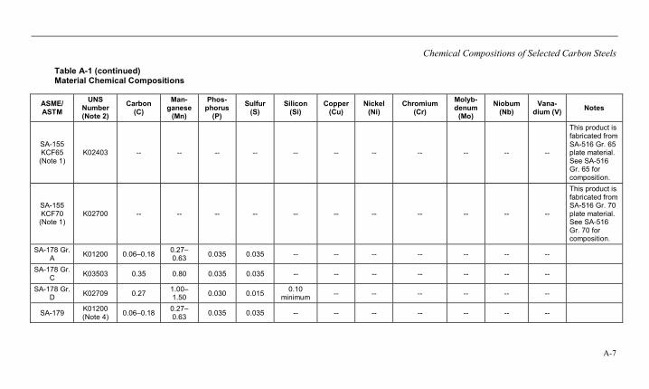
Chemical Compositions of Selected Carbon Steels
A-7
Table A-1 (continued) Material Chemical Compositions
ASME/ ASTM
UNS Number (Note 2)
Carbon (C)
Man-ganese
(Mn)
Phos-phorus
(P)
Sulfur (S)
Silicon (Si)
Copper(Cu)
Nickel (Ni)
Chromium (Cr)
Molyb-denum
(Mo)
Niobum (Nb)
Vana-dium (V) Notes
SA-155 KCF65 (Note 1)
K02403 -- -- -- -- -- -- -- -- -- -- --
This product is fabricated from SA-516 Gr. 65 plate material. See SA-516 Gr. 65 for composition.
SA-155 KCF70 (Note 1)
K02700 -- -- -- -- -- -- -- -- -- -- --
This product is fabricated from SA-516 Gr. 70 plate material. See SA-516 Gr. 70 for composition.
SA-178 Gr. A K01200 0.06–0.18 0.27–
0.63 0.035 0.035 -- -- -- -- -- -- --
SA-178 Gr. C K03503 0.35 0.80 0.035 0.035 -- -- -- -- -- -- --
SA-178 Gr. D K02709 0.27 1.00–
1.50 0.030 0.015 0.10 minimum -- -- -- -- -- --
SA-179 K01200 (Note 4) 0.06–0.18 0.27–
0.63 0.035 0.035 -- -- -- -- -- -- --
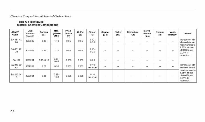
Chemical Compositions of Selected Carbon Steels
A-8
Table A-1 (continued) Material Chemical Compositions
ASME/ ASTM
UNS Number (Note 2)
Carbon (C)
Man-ganese
(Mn)
Phos-phorus
(P)
Sulfur (S)
Silicon (Si)
Copper (Cu)
Nickel (Ni)
Chromium (Cr)
Molyb-denum
(Mo)
Niobum (Nb)
Vana-dium (V) Notes
SA-181 Cl. 60 K03502 0.35 1.10 0.05 0.05 0.10–
0.35 -- -- -- -- -- --
SA-181 Cl. 70 K03502 0.35 1.10 0.05 0.05 0.10–
0.35 -- -- -- -- -- --
Increase of Mn allowed above maximum up to 1.35% at rate of 0.06% per 0.01% C reduction.
SA-192 K01201 0.06–0.18 0.27–0.63 0.035 0.035 0.25 -- -- -- -- -- --
SA-210 Gr. A1 K02707 0.27 0.93 0.035 0.035 0.10
minimum -- -- -- -- -- --
SA-210 Gr. C K03501 0.35 0.29–
1.06 0.035 0.035 0.10 minimum -- -- -- -- -- --
Increase of Mn allowed. above maximum up to 1.35% at rate of 0.06% per 0.01% C reduction.
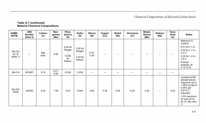
Chemical Compositions of Selected Carbon Steels
A-9
Table A-1 (continued) Material Chemical Compositions
ASME/ ASTM
UNS Number (Note 2)
Carbon (C)
Man-ganese
(Mn)
Phos-phorus
(P)
Sulfur (S)
Silicon (Si)
Copper (Cu)
Nickel (Ni)
Chromium (Cr)
Molyb-denum
(Mo)
Niobum (Nb)
Vana-dium (V)
Notes
SA-212 Gr. B
(Note 1) -- See
note. 0.90
0.04 for flanges
; 0.035
for firebox.
0.05 for flanges
; 0.04 for firebox.
0.15–0.30 -- -- -- -- -- --
Maximum C content: 0.31 for ≤ 1 in. 0.33 for > 1 in., ≤ 2 in. 0.35 for > 2 in., ≤ 8 in. Product analysis, Si: 0.13–0.33.
SA-214 K01807 0.18 0.27–0.63 0.035 0.035 -- -- -- -- -- -- --
SA-216 WCB J03002 0.30 1.00 0.04 0.045 0.60 0.30 0.50 0.50 0.20 -- 0.03
Increase of Mn allowed above maximum up to 1.28% at rate of 0.04% per 0.01% C reduction. 1.0% maximum for sum of Cu, Ni, Cr, Mo, and V.
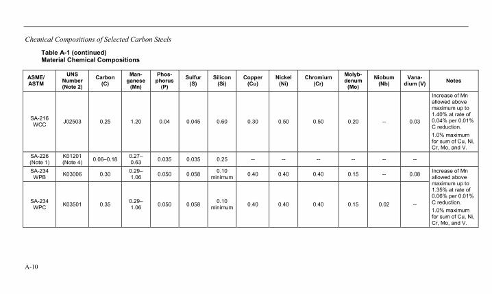
Chemical Compositions of Selected Carbon Steels
A-10
Table A-1 (continued) Material Chemical Compositions
ASME/ ASTM
UNS Number (Note 2)
Carbon (C)
Man-ganese
(Mn)
Phos-phorus
(P)
Sulfur (S)
Silicon (Si)
Copper (Cu)
Nickel (Ni)
Chromium (Cr)
Molyb-denum
(Mo)
Niobum (Nb)
Vana-dium (V) Notes
SA-216 WCC J02503 0.25 1.20 0.04 0.045 0.60 0.30 0.50 0.50 0.20 -- 0.03
Increase of Mn allowed above maximum up to 1.40% at rate of 0.04% per 0.01% C reduction. 1.0% maximum for sum of Cu, Ni, Cr, Mo, and V.
SA-226 (Note 1)
K01201 (Note 4) 0.06–0.18 0.27–
0.63 0.035 0.035 0.25 -- -- -- -- -- --
SA-234 WPB K03006 0.30 0.29–
1.06 0.050 0.058 0.10 minimum 0.40 0.40 0.40 0.15 -- 0.08
SA-234 WPC K03501 0.35 0.29–
1.06 0.050 0.058 0.10 minimum 0.40 0.40 0.40 0.15 0.02 --
Increase of Mn allowed above maximum up to 1.35% at rate of 0.06% per 0.01% C reduction. 1.0% maximum for sum of Cu, Ni, Cr, Mo, and V.
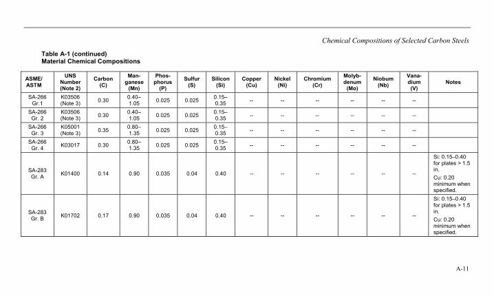
Chemical Compositions of Selected Carbon Steels
A-11
Table A-1 (continued) Material Chemical Compositions
ASME/ ASTM
UNS Number (Note 2)
Carbon (C)
Man-ganese
(Mn)
Phos-phorus
(P)
Sulfur (S)
Silicon (Si)
Copper (Cu)
Nickel (Ni)
Chromium (Cr)
Molyb-denum
(Mo)
Niobum (Nb)
Vana-dium (V)
Notes
SA-266 Gr.1
K03506 (Note 3) 0.30 0.40–
1.05 0.025 0.025 0.15–0.35 -- -- -- -- -- --
SA-266 Gr. 2
K03506 (Note 3) 0.30 0.40–
1.05 0.025 0.025 0.15–0.35 -- -- -- -- -- --
SA-266 Gr. 3
K05001 (Note 3) 0.35 0.80–
1.35 0.025 0.025 0.15–0.35 -- -- -- -- -- --
SA-266 Gr. 4 K03017 0.30 0.80–
1.35 0.025 0.025 0.15–0.35 -- -- -- -- -- --
SA-283 Gr. A K01400 0.14 0.90 0.035 0.04 0.40 -- -- -- -- -- --
Si: 0.15–0.40 for plates > 1.5 in. Cu: 0.20 minimum when specified.
SA-283 Gr. B K01702 0.17 0.90 0.035 0.04 0.40 -- -- -- -- -- --
Si: 0.15–0.40 for plates > 1.5 in. Cu: 0.20 minimum when specified.
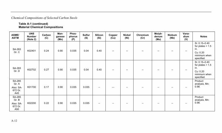
Chemical Compositions of Selected Carbon Steels
A-12
Table A-1 (continued) Material Chemical Compositions
ASME/ ASTM
UNS Number (Note 2)
Carbon (C)
Man-ganese
(Mn)
Phos-phorus
(P)
Sulfur (S)
Silicon (Si)
Copper (Cu)
Nickel (Ni)
Chromium (Cr)
Molyb-denum
(Mo)
Niobum (Nb)
Vana-dium (V)
Notes
SA-283 Gr. C K02401 0.24 0.90 0.035 0.04 0.40 -- -- -- -- -- --
Si: 0.15–0.40 for plates > 1.5 in. Cu: 0.20 minimum when specified.
SA-283 Gr. D K02702 0.27 0.90 0.035 0.04 0.40 -- -- -- -- -- --
Si: 0.15–0.40 for plates > 1.5 in. Cu: 0.20 minimum when specified.
SA-285 Gr. A
Also: SA-672 Gr.
A45
K01700 0.17 0.90 0.035 0.035 -- --- -- -- -- -- --
Product analysis, Mn: 0.98.
SA-285 Gr. B
Also: SA-672 Gr.
A50
K02200 0.22 0.90 0.035 0.035 -- -- -- -- -- -- --
Product analysis, Mn: 0.98.
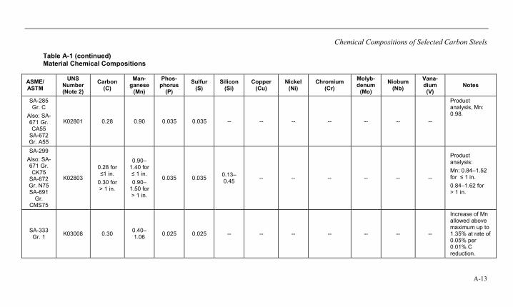
Chemical Compositions of Selected Carbon Steels
A-13
Table A-1 (continued) Material Chemical Compositions
ASME/ ASTM
UNS Number (Note 2)
Carbon (C)
Man-ganese
(Mn)
Phos-phorus
(P)
Sulfur (S)
Silicon (Si)
Copper (Cu)
Nickel (Ni)
Chromium (Cr)
Molyb-denum
(Mo)
Niobum (Nb)
Vana-dium (V)
Notes
SA-285 Gr. C
Also: SA-671 Gr. CA55
SA-672 Gr. A55
K02801 0.28 0.90 0.035 0.035 -- -- -- -- -- -- --
Product analysis, Mn: 0.98.
SA-299 Also: SA-671 Gr. CK75
SA-672 Gr. N75 SA-691
Gr. CMS75
K02803
0.28 for ≤1 in.
0.30 for > 1 in.
0.90–1.40 for ≤ 1 in. 0.90–
1.50 for > 1 in.
0.035 0.035 0.13–0.45 -- -- -- -- -- --
Product analysis: Mn: 0.84–1.52 for ≤ 1 in. 0.84–1.62 for > 1 in.
SA-333 Gr. 1 K03008 0.30 0.40–
1.06 0.025 0.025 -- -- -- -- -- -- --
Increase of Mn allowed above maximum up to 1.35% at rate of 0.05% per 0.01% C reduction.

Chemical Compositions of Selected Carbon Steels
A-14
Table A-1 (continued) Material Chemical Compositions
ASME/ ASTM
UNS Number (Note 2)
Carbon (C)
Man-ganese
(Mn)
Phos-phorus
(P)
Sulfur (S)
Silicon (Si)
Copper (Cu)
Nickel (Ni)
Chromium (Cr)
Molyb-denum
(Mo)
Niobum (Nb)
Vana-dium (V) Notes
SA-333 Gr. 6 K03006 0.30 0.29–
1.06 0.025 0.025 0.10 minimum -- -- -- -- -- --
Increase of Mn allowed above maximum up to 1.35% at rate of 0.05% per 0.01% C reduction.
SA-334 Gr. 1 K03008 0.30 0.40–
1.06 0.025 0.025 -- -- -- -- -- -- --
Increase of Mn allowed above maximum up to 1.35% at rate of 0.05% per 0.01% C reduction.
SA-334 Gr. 6 K03006 0.30 0.29–
1.06 0.025 0.025 0.10 minimum -- -- -- -- -- --
Increase of Mn allowed above maximum up to 1.35% at rate of 0.05% per 0.01% C reduction.
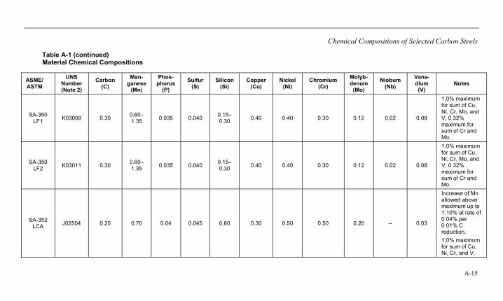
Chemical Compositions of Selected Carbon Steels
A-15
Table A-1 (continued) Material Chemical Compositions
ASME/ ASTM
UNS Number (Note 2)
Carbon (C)
Man-ganese
(Mn)
Phos-phorus
(P)
Sulfur (S)
Silicon (Si)
Copper (Cu)
Nickel (Ni)
Chromium (Cr)
Molyb-denum
(Mo)
Niobum (Nb)
Vana-dium (V)
Notes
SA-350 LF1 K03009 0.30 0.60–
1.35 0.035 0.040 0.15–0.30 0.40 0.40 0.30 0.12 0.02 0.08
1.0% maximum for sum of Cu, Ni, Cr, Mo, and V; 0.32% maximum for sum of Cr and Mo.
SA-350 LF2 K03011 0.30 0.60–
1.35 0.035 0.040 0.15–0.30 0.40 0.40 0.30 0.12 0.02 0.08
1.0% maximum for sum of Cu, Ni, Cr, Mo, and V; 0.32% maximum for sum of Cr and Mo.
SA-352 LCA J02504 0.25 0.70 0.04 0.045 0.60 0.30 0.50 0.50 0.20 -- 0.03
Increase of Mn allowed above maximum up to 1.10% at rate of 0.04% per 0.01% C reduction. 1.0% maximum for sum of Cu, Ni, Cr, and V.
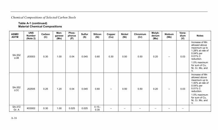
Chemical Compositions of Selected Carbon Steels
A-16
Table A-1 (continued) Material Chemical Compositions
ASME/ ASTM
UNS Number (Note 2)
Carbon (C)
Man-ganese
(Mn)
Phos-phorus
(P)
Sulfur (S)
Silicon (Si)
Copper (Cu)
Nickel (Ni)
Chromium (Cr)
Molyb-denum
(Mo)
Niobum (Nb)
Vana-dium (V)
Notes
SA-352 LCB J03003 0.30 1.00 0.04 0.045 0.60 0.30 0.50 0.50 0.20 -- 0.03
Increase of Mn allowed above maximum up to 1.28% at rate of 0.04% per 0.01% C reduction. 1.0% maximum for sum of Cu, Ni, Cr, Mo, and V.
SA-352 LCC J02505 0.25 1.20 0.04 0.045 0.60 -- 0.50 0.50 0.20 -- 0.03
Increase of Mn allowed above maximum up to 1.40% at rate of 0.04% per 0.01% C reduction. 1.0% maximum for sum of Cu, Ni, Cr, Mo, and V.
SA-372 Gr. A K03002 0.30 1.00 0.025 0.025 0.15–
0.35 -- -- -- -- -- --
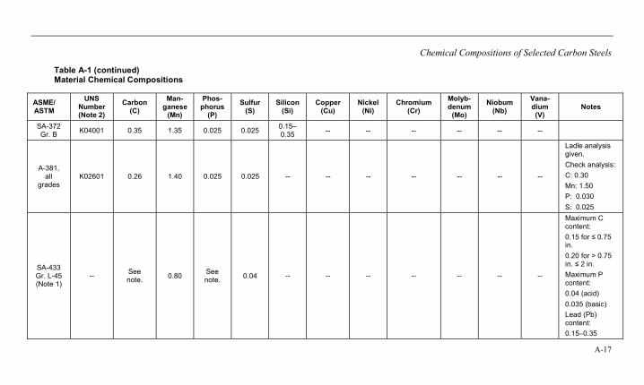
Chemical Compositions of Selected Carbon Steels
A-17
Table A-1 (continued) Material Chemical Compositions
ASME/ ASTM
UNS Number (Note 2)
Carbon (C)
Man-ganese
(Mn)
Phos-phorus
(P)
Sulfur (S)
Silicon (Si)
Copper (Cu)
Nickel (Ni)
Chromium (Cr)
Molyb-denum
(Mo)
Niobum (Nb)
Vana-dium (V)
Notes
SA-372 Gr. B K04001 0.35 1.35 0.025 0.025 0.15–
0.35 -- -- -- -- -- --
A-381, all
grades K02601 0.26 1.40 0.025 0.025 -- -- -- -- -- -- --
Ladle analysis given. Check analysis: C: 0.30 Mn: 1.50 P: 0.030 S: 0.025
SA-433 Gr. L-45 (Note 1)
-- See note. 0.80 See
note. 0.04 -- -- -- -- -- -- --
Maximum C content: 0.15 for ≤ 0.75 in. 0.20 for > 0.75 in. ≤ 2 in. Maximum P content: 0.04 (acid) 0.035 (basic) Lead (Pb) content: 0.15–0.35
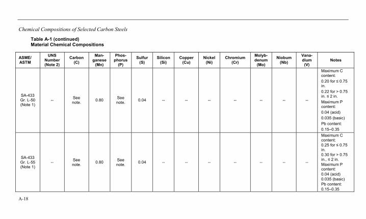
Chemical Compositions of Selected Carbon Steels
A-18
Table A-1 (continued) Material Chemical Compositions
ASME/ ASTM
UNS Number (Note 2)
Carbon (C)
Man-ganese
(Mn)
Phos-phorus
(P)
Sulfur (S)
Silicon (Si)
Copper (Cu)
Nickel (Ni)
Chromium (Cr)
Molyb-denum
(Mo)
Niobum (Nb)
Vana-dium (V)
Notes
SA-433 Gr. L-50 (Note 1)
-- See note. 0.80 See
note. 0.04 -- -- -- -- -- -- --
Maximum C content: 0.20 for ≤ 0.75 in. 0.22 for > 0.75 in. ≤ 2 in. Maximum P content: 0.04 (acid) 0.035 (basic) Pb content: 0.15–0.35
SA-433 Gr. L-55 (Note 1)
-- See note. 0.80 See
note. 0.04 -- -- -- -- -- -- --
Maximum C content: 0.25 for ≤ 0.75 in. 0.30 for > 0.75 in., ≤ 2 in. Maximum P content: 0.04 (acid) 0.035 (basic) Pb content: 0.15–0.35
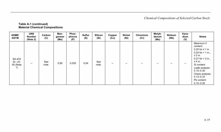
Chemical Compositions of Selected Carbon Steels
A-19
Table A-1 (continued) Material Chemical Compositions
ASME/ ASTM
UNS Number (Note 2)
Carbon (C)
Man-ganese
(Mn)
Phos-phorus
(P)
Sulfur (S)
Silicon (Si)
Copper (Cu)
Nickel (Ni)
Chromium (Cr)
Molyb-denum
(Mo)
Niobum (Nb)
Vana-dium (V)
Notes
SA-433 Gr. LK-
55 (Note 1)
-- See note. 0.80 0.035 0.04 See
note. -- -- -- -- -- --
Maximum C content: 0.20 for ≤ 1 in. 0.24 for > 1 in., ≤ 2 in. 0.27 for > 2 in., ≤ 4 in. Si content: Ladle analysis: 0.15–0.30 Check analysis: 0.13–0.33 Pb content: 0.15–0.35
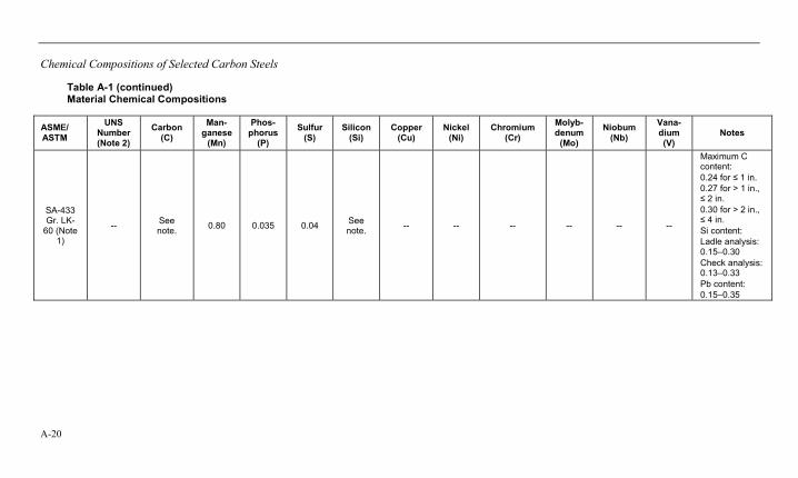
Chemical Compositions of Selected Carbon Steels
A-20
Table A-1 (continued) Material Chemical Compositions
ASME/ ASTM
UNS Number (Note 2)
Carbon (C)
Man-ganese
(Mn)
Phos-phorus
(P)
Sulfur (S)
Silicon (Si)
Copper (Cu)
Nickel (Ni)
Chromium (Cr)
Molyb-denum
(Mo)
Niobum (Nb)
Vana-dium (V)
Notes
SA-433 Gr. LK-
60 (Note 1)
-- See note. 0.80 0.035 0.04 See
note. -- -- -- -- -- --
Maximum C content: 0.24 for ≤ 1 in. 0.27 for > 1 in., ≤ 2 in. 0.30 for > 2 in., ≤ 4 in. Si content: Ladle analysis: 0.15–0.30 Check analysis: 0.13–0.33 Pb content: 0.15–0.35

Chemical Compositions of Selected Carbon Steels
A-21
Table A-1 (continued) Material Chemical Compositions
ASME/ ASTM
UNS Number (Note 2)
Carbon (C)
Man-ganese
(Mn)
Phos-phorus
(P)
Sulfur (S)
Silicon (Si)
Copper (Cu)
Nickel (Ni)
Chromium (Cr)
Molyb-denum
(Mo)
Niobum (Nb)
Vana-dium (V)
Notes
SA-433 Gr. LK-
65 (Note 1)
-- See note. 0.80 0.035 0.04 See
note. -- -- -- -- -- --
Maximum C content: 0.28 for ≤ 1 in. 0.31 for >1 in., ≤ 2 in. 0.33 for >2 in., ≤ 4 in. Si content: Ladle analysis: 0.15–0.30 Check analysis: 0.13–0.33 Pb content: 0.15–0.35
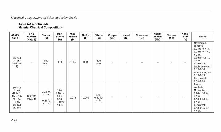
Chemical Compositions of Selected Carbon Steels
A-22
Table A-1 (continued) Material Chemical Compositions
ASME/ ASTM
UNS Number (Note 2)
Carbon (C)
Man-ganese
(Mn)
Phos-phorus
(P)
Sulfur (S)
Silicon (Si)
Copper (Cu)
Nickel (Ni)
Chromium (Cr)
Molyb-denum
(Mo)
Niobum (Nb)
Vana-dium (V)
Notes
SA-433 Gr. LK-
70 (Note 1)
-- See note. 0.80 0.035 0.04 See
note. -- -- -- -- -- --
Maximum C content: 0.31 for ≤ 1 in. 0.33 for >1 in., ≤ 2 in. 0.35 for >2 in., ≤ 4 in. Si content: Ladle analysis: 0.15–0.30 Check analysis: 0.13–0.33 Pb content: 0.15–0.35
SA-442 Gr.55
(Note 1) Also: SA-671 Gr. CE55
SA-672 Gr. E55
K02202 (Note 4)
0.22 for ≤ 1 in.
0.24 for > 1 in.
0.80–1.10 for ≤ 1 in. 0.60–
0.90 for > 1 in.
0.035 0.040 0.15–
0.40 for > 1 in.
-- -- -- -- -- --
Product analysis: Mn content 0.74–1.20 for ≤ 1 in. 0.55–0.98 for > 1 in. Si content: 0.13–0.45 for > 1 in.
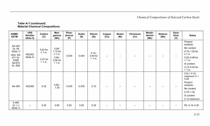
Chemical Compositions of Selected Carbon Steels
A-23
Table A-1 (continued) Material Chemical Compositions
ASME/ ASTM
UNS Number (Note 2)
Carbon (C)
Man-ganese
(Mn)
Phos-phorus
(P)
Sulfur (S)
Silicon (Si)
Copper (Cu)
Nickel (Ni)
Chromium (Cr)
Molyb-denum
(Mo)
Niobum (Nb)
Vana-dium (V)
Notes
SA-442 Gr. 60
(Note 1) Also: SA-671 Gr. CE60
SA-672 Gr. E60
K02402 (Note 4)
0.24 for ≤ 1 in.
0.27 for > 1 in.
0.80-1.10 for ≤ 1 in. 0.60–
0.90 for > 1 in.
0.035 0.040 0.15–
0.40 for > 1 in.
-- -- -- -- -- --
Product analysis: Mn content 0.74–1.20 for ≤ 1 in. 0.55–0.98 for > 1 in. Si content: 0.13–0.45 for > 1 in.
SA-455 K03300 0.33 0.85–1.20 0.035 0.035 0.10 -- -- -- -- -- --
If Si > 0.10, maximum C = 0.28 Product analysis: Mn content 0.79–1.30 Si content 0.13 maximum
A-465 Gr. L-I
(Note 1) -- 0.30 0.90 0.05 0.05 0.35 -- -- -- -- -- -- Pb: 0.15–0.35
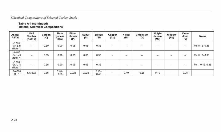
Chemical Compositions of Selected Carbon Steels
A-24
Table A-1 (continued) Material Chemical Compositions
ASME/ ASTM
UNS Number (Note 2)
Carbon (C)
Man-ganese
(Mn)
Phos-phorus
(P)
Sulfur (S)
Silicon (Si)
Copper (Cu)
Nickel (Ni)
Chromium (Cr)
Molyb-denum
(Mo)
Niobum (Nb)
Vana-dium (V)
Notes
A-465 Gr. L-II (Note 1)
-- 0.30 0.90 0.05 0.05 0.35 -- -- -- -- -- -- Pb: 0.15–0.35
A-465 Gr. L-III (Note 1)
-- 0.35 0.90 0.05 0.05 0.35 -- -- -- -- -- -- Pb: 0.15–0.35
A-465 Gr. L-IV (Note 1)
-- 0.35 0.90 0.05 0.05 0.35 -- -- -- -- -- -- Pb – 0.15–0.35
SA-508 Gr. 1 K13502 0.35 0.40–
1.05 0.025 0.025 0.15–0.40 -- 0.40 0.25 0.10 -- 0.05
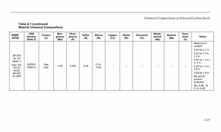
Chemical Compositions of Selected Carbon Steels
A-25
Table A-1 (continued) Material Chemical Compositions
ASME/ ASTM
UNS Number (Note 2)
Carbon (C)
Man-ganese
(Mn)
Phos-phorus
(P)
Sulfur (S)
Silicon (Si)
Copper (Cu)
Nickel (Ni)
Chromium (Cr)
Molyb-denum
(Mo)
Niobum (Nb)
Vana-dium (V)
Notes
SA-515 Gr. 55
(Note 1) Also: SA-155 Gr. KC55
SA-672 Gr. B55
K02001 (Note 5)
See note. 0.90 0.035 0.04 0.15–
0.40 -- -- -- -- -- --
Maximum C content: 0.20 for ≤ 1 in. 0.22 for >1 in., ≤ 2 in. 0.24 for > 2 in., ≤ 4 in. 0.26 for > 4 in., ≤ 8 in. 0.28 for > 8 in. Mn and Si product analyses: Mn: 0.98; Si: 0.13–0.45
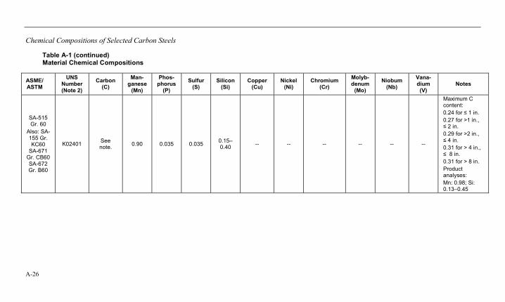
Chemical Compositions of Selected Carbon Steels
A-26
Table A-1 (continued) Material Chemical Compositions
ASME/ ASTM
UNS Number (Note 2)
Carbon (C)
Man-ganese
(Mn)
Phos-phorus
(P)
Sulfur (S)
Silicon (Si)
Copper (Cu)
Nickel (Ni)
Chromium (Cr)
Molyb-denum
(Mo)
Niobum (Nb)
Vana-dium (V)
Notes
SA-515 Gr. 60
Also: SA-155 Gr. KC60
SA-671 Gr. CB60 SA-672 Gr. B60
K02401 See note. 0.90 0.035 0.035 0.15–
0.40 -- -- -- -- -- --
Maximum C content: 0.24 for ≤ 1 in. 0.27 for >1 in., ≤ 2 in. 0.29 for >2 in., ≤ 4 in. 0.31 for > 4 in., ≤ 8 in. 0.31 for > 8 in. Product analyses: Mn: 0.98; Si: 0.13–0.45
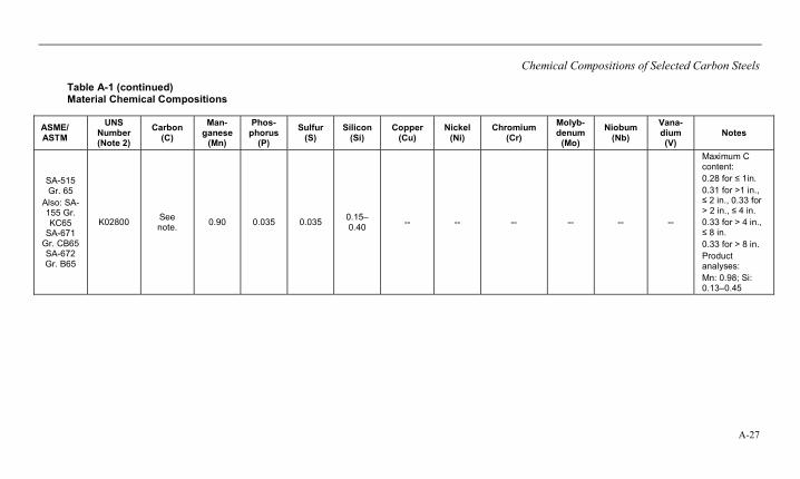
Chemical Compositions of Selected Carbon Steels
A-27
Table A-1 (continued) Material Chemical Compositions
ASME/ ASTM
UNS Number (Note 2)
Carbon (C)
Man-ganese
(Mn)
Phos-phorus
(P)
Sulfur (S)
Silicon (Si)
Copper (Cu)
Nickel (Ni)
Chromium (Cr)
Molyb-denum
(Mo)
Niobum (Nb)
Vana-dium (V)
Notes
SA-515 Gr. 65
Also: SA-155 Gr. KC65
SA-671 Gr. CB65 SA-672 Gr. B65
K02800 See note. 0.90 0.035 0.035 0.15–
0.40 -- -- -- -- -- --
Maximum C content: 0.28 for ≤ 1in. 0.31 for >1 in., ≤ 2 in., 0.33 for > 2 in., ≤ 4 in. 0.33 for > 4 in., ≤ 8 in. 0.33 for > 8 in. Product analyses: Mn: 0.98; Si: 0.13–0.45
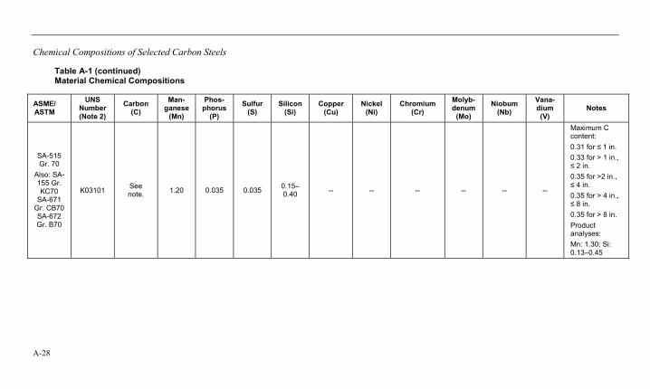
Chemical Compositions of Selected Carbon Steels
A-28
Table A-1 (continued) Material Chemical Compositions
ASME/ ASTM
UNS Number (Note 2)
Carbon (C)
Man-ganese
(Mn)
Phos-phorus
(P)
Sulfur (S)
Silicon (Si)
Copper (Cu)
Nickel (Ni)
Chromium (Cr)
Molyb-denum
(Mo)
Niobum (Nb)
Vana-dium (V)
Notes
SA-515 Gr. 70
Also: SA-155 Gr. KC70
SA-671 Gr. CB70 SA-672 Gr. B70
K03101 See note. 1.20 0.035 0.035 0.15–
0.40 -- -- -- -- -- --
Maximum C content: 0.31 for ≤ 1 in. 0.33 for > 1 in., ≤ 2 in. 0.35 for >2 in., ≤ 4 in. 0.35 for > 4 in., ≤ 8 in. 0.35 for > 8 in. Product analyses: Mn: 1.30; Si: 0.13–0.45
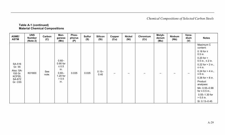
Chemical Compositions of Selected Carbon Steels
A-29
Table A-1 (continued) Material Chemical Compositions
ASME/ ASTM
UNS Number (Note 2)
Carbon (C)
Man-ganese
(Mn)
Phos-phorus
(P)
Sulfur (S)
Silicon (Si)
Copper (Cu)
Nickel (Ni)
Chromium (Cr)
Molyb-denum
(Mo)
Niobum (Nb)
Vana-dium (V)
Notes
SA-516 Gr. 55
Also: SA-155 Gr. KCF55, SA-672 Gr. C55
K01800 See note.
0.60–0.90 for ≤ 0.5
in. 0.60–
1.20 for > 0.5
in.
0.035 0.035 0.15–0.40 -- -- -- -- -- --
Maximum C content: 0.18 for ≤ 0.5 in. 0.20 for > 0.5 in., ≤ 2 in. 0.22 for > 2 in., ≤ 4 in. 0.24 for > 4 in., ≤ 8 in. 0.26 for > 8 in. Product analyses: Mn: 0.55–0.98 for ≤ 0.5 in., 0.55–1.30 for > 0.5 in. Si: 0.13–0.45

Chemical Compositions of Selected Carbon Steels
A-30
Table A-1 (continued) Material Chemical Compositions
ASME/ ASTM
UNS Number (Note 2)
Carbon (C)
Man-ganese
(Mn)
Phos-phorus
(P)
Sulfur (S)
Silicon (Si)
Copper (Cu)
Nickel (Ni)
Chromium (Cr)
Molyb-denum
(Mo)
Niobum (Nb)
Vana-dium (V)
Notes
SA-516 Gr. 60
Also: SA-155Gr. KCF60, SA-671
Gr. CC60, SA-672 Gr. C60
K02100 See note.
0.60–0.90 for ≤ 0.5
in.
0.85–1.20 for
> 0.5 in.
0.035 0.035 0.15–0.40 -- -- -- -- -- --
Maximum C content: 0.21 for ≤ 0.5 in. 0.23 for > 0.5 in., ≤ 2 in. 0.25 for > 2 in., ≤ 4 in. 0.27 for > 4 in., ≤ 8 in. 0.27 for > 8 in. Product analyses: Mn: 0.55–0.98 for ≤ 0.5 in., 0.79–1.30 for > 0.5 in. Si: 0.13–0.45
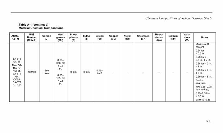
Chemical Compositions of Selected Carbon Steels
A-31
Table A-1 (continued) Material Chemical Compositions
ASME/ ASTM
UNS Number (Note 2)
Carbon (C)
Man-ganese
(Mn)
Phos-phorus
(P)
Sulfur (S)
Silicon (Si)
Copper (Cu)
Nickel (Ni)
Chromium (Cr)
Molyb-denum
(Mo)
Niobum (Nb)
Vana-dium (V)
Notes
SA-516 Gr. 65
Also: SA-155 Gr. KCF65, SA-671
Gr. CC65, SA-672 Gr. C65
K02403 See note.
0.60–0.90 for ≤ 0.5
in.
0.85–1.20 for
> 0.5 in.
0.035 0.035 0.15–0.40 -- -- -- -- -- --
Maximum C content: 0.24 for ≤ 0.5 in. 0.26 for > 0.5 in., ≤ 2 in. 0.28 for > 2 in., ≤ 4 in. 0.29 for > 4 in., ≤ 8 in. 0.29 for > 8 in. Product analyses: Mn: 0.55–0.98 for ≤ 0.5 in., 0.79–1.30 for > 0.5 in. Si: 0.13–0.45
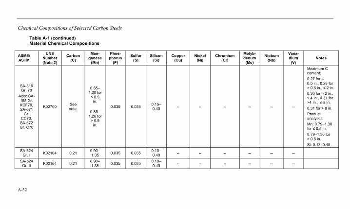
Chemical Compositions of Selected Carbon Steels
A-32
Table A-1 (continued) Material Chemical Compositions
ASME/ ASTM
UNS Number (Note 2)
Carbon (C)
Man-ganese
(Mn)
Phos-phorus
(P)
Sulfur (S)
Silicon (Si)
Copper (Cu)
Nickel (Ni)
Chromium (Cr)
Molyb-denum
(Mo)
Niobum (Nb)
Vana-dium (V)
Notes
SA-516 Gr. 70
Also: SA-155 Gr. KCF70, SA-671
Gr. CC70, SA-672 Gr. C70
K02700 See note.
0.85–1.20 for ≤ 0.5
in.
0.85–1.20 for
> 0.5 in.
0.035 0.035 0.15–0.40 -- -- -- -- -- --
Maximum C content: 0.27 for ≤ 0.5 in., 0.28 for > 0.5 in., ≤ 2 in. 0.30 for > 2 in., ≤ 4 in., 0.31 for >4 in., ≤ 8 in. 0.31 for > 8 in. Product analyses: Mn: 0.79–1.30 for ≤ 0.5 in. 0.79–1.30 for > 0.5 in. Si: 0.13–0.45
SA-524 Gr. I K02104 0.21 0.90–
1.35 0.035 0.035 0.10–0.40 -- -- -- -- -- --
SA-524 Gr. II K02104 0.21 0.90–
1.35 0.035 0.035 0.10–0.40 -- -- -- -- -- --
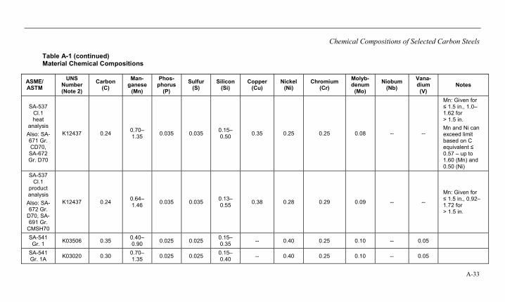
Chemical Compositions of Selected Carbon Steels
A-33
Table A-1 (continued) Material Chemical Compositions
ASME/ ASTM
UNS Number (Note 2)
Carbon (C)
Man-ganese
(Mn)
Phos-phorus
(P)
Sulfur (S)
Silicon (Si)
Copper (Cu)
Nickel (Ni)
Chromium (Cr)
Molyb-denum
(Mo)
Niobum (Nb)
Vana-dium (V)
Notes
SA-537 Cl.1 heat
analysis Also: SA-671 Gr. CD70, SA-672 Gr. D70
K12437 0.24 0.70–1.35 0.035 0.035 0.15–
0.50 0.35 0.25 0.25 0.08 -- --
Mn: Given for ≤ 1.5 in., 1.0–1.62 for > 1.5 in. Mn and Ni can exceed limit based on C equivalent ≤ 0.57 – up to 1.60 (Mn) and 0.50 (Ni)
SA-537 Cl.1
product analysis Also: SA-672 Gr.
D70, SA-691 Gr.
CMSH70
K12437 0.24 0.64–1.46 0.035 0.035 0.13–
0.55 0.38 0.28 0.29 0.09 -- --
Mn: Given for ≤ 1.5 in., 0.92–1.72 for > 1.5 in.
SA-541 Gr. 1 K03506 0.35 0.40–
0.90 0.025 0.025 0.15–0.35 -- 0.40 0.25 0.10 -- 0.05
SA-541 Gr. 1A K03020 0.30 0.70–
1.35 0.025 0.025 0.15–0.40 -- 0.40 0.25 0.10 -- 0.05
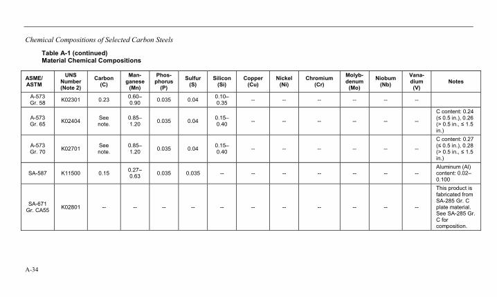
Chemical Compositions of Selected Carbon Steels
A-34
Table A-1 (continued) Material Chemical Compositions
ASME/ ASTM
UNS Number (Note 2)
Carbon (C)
Man-ganese
(Mn)
Phos-phorus
(P)
Sulfur (S)
Silicon (Si)
Copper (Cu)
Nickel (Ni)
Chromium (Cr)
Molyb-denum
(Mo)
Niobum (Nb)
Vana-dium (V)
Notes
A-573 Gr. 58 K02301 0.23 0.60–
0.90 0.035 0.04 0.10–0.35 -- -- -- -- -- --
A-573 Gr. 65 K02404 See
note. 0.85–1.20 0.035 0.04 0.15–
0.40 -- -- -- -- -- --
C content: 0.24 (≤ 0.5 in.), 0.26 (> 0.5 in., ≤ 1.5 in.)
A-573 Gr. 70 K02701 See
note. 0.85–1.20 0.035 0.04 0.15–
0.40 -- -- -- -- -- --
C content: 0.27 (≤ 0.5 in.), 0.28 (> 0.5 in., ≤ 1.5 in.)
SA-587 K11500 0.15 0.27–0.63 0.035 0.035 -- -- -- -- -- -- --
Aluminum (Al) content: 0.02–0.100
SA-671 Gr. CA55 K02801 -- -- -- -- -- -- -- -- -- -- --
This product is fabricated from SA-285 Gr. C plate material. See SA-285 Gr. C for composition.
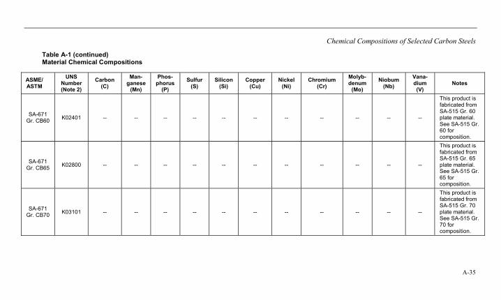
Chemical Compositions of Selected Carbon Steels
A-35
Table A-1 (continued) Material Chemical Compositions
ASME/ ASTM
UNS Number (Note 2)
Carbon (C)
Man-ganese
(Mn)
Phos-phorus
(P)
Sulfur (S)
Silicon (Si)
Copper (Cu)
Nickel (Ni)
Chromium (Cr)
Molyb-denum
(Mo)
Niobum (Nb)
Vana-dium (V)
Notes
SA-671 Gr. CB60 K02401 -- -- -- -- -- -- -- -- -- -- --
This product is fabricated from SA-515 Gr. 60 plate material. See SA-515 Gr. 60 for composition.
SA-671 Gr. CB65 K02800 -- -- -- -- -- -- -- -- -- -- --
This product is fabricated from SA-515 Gr. 65 plate material. See SA-515 Gr. 65 for composition.
SA-671 Gr. CB70 K03101 -- -- -- -- -- -- -- -- -- -- --
This product is fabricated from SA-515 Gr. 70 plate material. See SA-515 Gr. 70 for composition.

Chemical Compositions of Selected Carbon Steels
A-36
Table A-1 (continued) Material Chemical Compositions
ASME/ ASTM
UNS Number (Note 2)
Carbon (C)
Man-ganese
(Mn)
Phos-phorus
(P)
Sulfur (S)
Silicon (Si)
Copper (Cu)
Nickel (Ni)
Chromium (Cr)
Molyb-denum
(Mo)
Niobum (Nb)
Vana-dium (V)
Notes
SA-671 Gr.
CC60 K02100 -- -- -- -- -- -- -- -- -- -- --
This product is fabricated from SA-516 Gr. 60 plate material. See SA-516 Gr. 60 for composition.
SA-671 Gr.
CC65 K02403 -- -- -- -- -- -- -- -- -- -- --
This product is fabricated from SA-516 Gr. 65 plate material. See SA-516 Gr. 65 for composition.
SA-671 Gr.
CC70 K02700 -- -- -- -- -- -- -- -- -- -- --
This product is fabricated from SA-516 Gr. 70 plate material. See SA-516 Gr. 70 for composition.
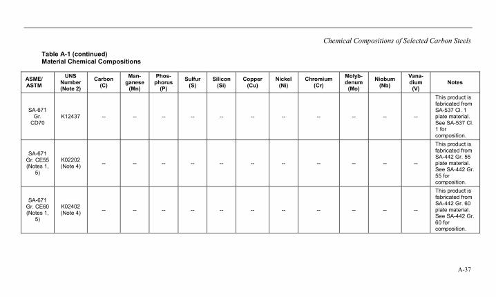
Chemical Compositions of Selected Carbon Steels
A-37
Table A-1 (continued) Material Chemical Compositions
ASME/ ASTM
UNS Number (Note 2)
Carbon (C)
Man-ganese
(Mn)
Phos-phorus
(P)
Sulfur (S)
Silicon (Si)
Copper (Cu)
Nickel (Ni)
Chromium (Cr)
Molyb-denum
(Mo)
Niobum (Nb)
Vana-dium (V)
Notes
SA-671 Gr.
CD70 K12437 -- -- -- -- -- -- -- -- -- -- --
This product is fabricated from SA-537 Cl. 1 plate material. See SA-537 Cl. 1 for composition.
SA-671 Gr. CE55 (Notes 1,
5)
K02202 (Note 4) -- -- -- -- -- -- -- -- -- -- --
This product is fabricated from SA-442 Gr. 55 plate material. See SA-442 Gr. 55 for composition.
SA-671 Gr. CE60 (Notes 1,
5)
K02402 (Note 4) -- -- -- -- -- -- -- -- -- -- --
This product is fabricated from SA-442 Gr. 60 plate material. See SA-442 Gr. 60 for composition.

Chemical Compositions of Selected Carbon Steels
A-38
Table A-1 (continued) Material Chemical Compositions
ASME/ ASTM
UNS Number (Note 2)
Carbon (C)
Man-ganese
(Mn)
Phos-phorus
(P)
Sulfur (S)
Silicon (Si)
Copper (Cu)
Nickel (Ni)
Chromium (Cr)
Molyb-denum
(Mo)
Niobum (Nb)
Vana-dium (V)
Notes
SA-671 Gr. CK75 K02803 -- -- -- -- -- -- -- -- -- -- --
This product is fabricated from SA-299 plate material. See SA-299 for composition.
SA-672 Gr. A45 K01700 -- -- -- -- -- -- -- -- -- -- --
This product is fabricated from SA-285 Gr. A plate material. See SA-285 Gr.A for composition.
SA-672 Gr. A50 K02200 -- -- -- -- -- -- -- -- -- -- --
This product is fabricated from SA-285 Gr. B plate material. See SA-285 Gr.B for composition.
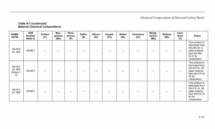
Chemical Compositions of Selected Carbon Steels
A-39
Table A-1 (continued) Material Chemical Compositions
ASME/ ASTM
UNS Number (Note 2)
Carbon (C)
Man-ganese
(Mn)
Phos-phorus
(P)
Sulfur (S)
Silicon (Si)
Copper (Cu)
Nickel (Ni)
Chromium (Cr)
Molyb-denum
(Mo)
Niobum (Nb)
Vana-dium (V)
Notes
SA-672 Gr. A55 K02801 -- -- -- -- -- -- -- -- -- -- --
This product is fabricated from SA-285 Gr. C plate material. See SA-285 Gr.C for composition.
SA-672 Gr. B55
(Notes 1, 5)
K02001 -- -- -- -- -- -- -- -- -- -- --
This product is fabricated from SA-515 Gr. 55 plate material. See SA-515 Gr. 55 for composition.
SA-672 Gr. B60 K02401 -- -- -- -- -- -- -- -- -- -- --
This product is fabricated from SA-515 Gr. 60 plate material. See SA-515 Gr. 60 for composition.

Chemical Compositions of Selected Carbon Steels
A-40
Table A-1 (continued) Material Chemical Compositions
ASME/ ASTM
UNS Number (Note 2)
Carbon (C)
Man-ganese
(Mn)
Phos-phorus
(P)
Sulfur (S)
Silicon (Si)
Copper (Cu)
Nickel (Ni)
Chromium (Cr)
Molyb-denum
(Mo)
Niobum (Nb)
Vana-dium (V)
Notes
SA-672 Gr. B65 K02800 -- -- -- -- -- -- -- -- -- -- --
This product is fabricated from SA-515 Gr. 65 plate material. See SA-515 Gr. 65 for composition.
SA-672 Gr. B70 K03101 -- -- -- -- -- -- -- -- -- -- --
This product is fabricated from SA-515 Gr. 70 plate material. See SA-515 Gr. 70 for composition.
SA-672 Gr. C55 K01800 -- -- -- -- -- -- -- -- -- -- --
This product is fabricated from SA-516 Gr. 55 plate material. See SA-516 Gr. 55 for composition.

Chemical Compositions of Selected Carbon Steels
A-41
Table A-1 (continued) Material Chemical Compositions
ASME/ ASTM
UNS Number (Note 2)
Carbon (C)
Man-ganese
(Mn)
Phos-phorus
(P)
Sulfur (S)
Silicon (Si)
Copper (Cu)
Nickel (Ni)
Chromium (Cr)
Molyb-denum
(Mo)
Niobum (Nb)
Vana-dium (V)
Notes
SA-672 Gr. C60 K02100 -- -- -- -- -- -- -- -- -- -- --
This product is fabricated from SA-516 Gr. 60 plate material. See SA-516 Gr. 60 for composition.
SA-672 Gr. C65 K02403 -- -- -- -- -- -- -- -- -- -- --
This product is fabricated from SA-516 Gr. 65 plate material. See SA-516 Gr. 65 for composition.
SA-672 Gr. C70 K02700 -- -- -- -- -- -- -- -- -- -- --
This product is fabricated from SA-516 Gr. 70 plate material. See SA-516 Gr. 70 for composition.
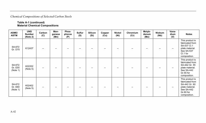
Chemical Compositions of Selected Carbon Steels
A-42
Table A-1 (continued) Material Chemical Compositions
ASME/ ASTM
UNS Number (Note 2)
Carbon (C)
Man-ganese
(Mn)
Phos-phorus
(P)
Sulfur (S)
Silicon (Si)
Copper (Cu)
Nickel (Ni)
Chromium (Cr)
Molyb-denum
(Mo)
Niobum (Nb)
Vana-dium (V)
Notes
SA-672 Gr. D70 K12437 -- -- -- -- -- -- -- -- -- -- --
This product is fabricated from SA-537 Cl.1 plate material. See SA-537 Cl.1 for composition.
SA-672 Gr. E55 (Note 1)
K02202 (Note 5) -- -- -- -- -- -- -- -- -- -- --
This product is fabricated from SA-442 Gr. 55 plate material. See SA-442 Gr.55 for composition.
SA-672 Gr. E60 (Note 1)
K02402 (Note 5) -- -- -- -- -- -- -- -- -- -- --
This product is fabricated from SA-442 Gr. 60 plate material. See SA-442 Gr.60 for composition.
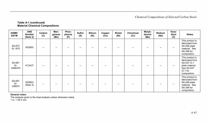
Chemical Compositions of Selected Carbon Steels
A-43
Table A-1 (continued) Material Chemical Compositions
ASME/ ASTM
UNS Number (Note 2)
Carbon (C)
Man-ganese
(Mn)
Phos-phorus
(P)
Sulfur (S)
Silicon (Si)
Copper (Cu)
Nickel (Ni)
Chromium (Cr)
Molyb-denum
(Mo)
Niobum (Nb)
Vana-dium (V)
Notes
SA-672 Gr. N75 K02803 -- -- -- -- -- -- -- -- -- -- --
This product is fabricated from SA-299 plate material. See SA-299 for composition.
SA-691 Gr.
CMSH70 K12437 -- -- -- -- -- -- -- -- -- -- --
This product is fabricated from SA-537 Cl.1 plate material. See SA-537 Cl.1 for composition.
SA-691 Gr.
CMS75
K02803 (Note 3) -- -- -- -- -- -- -- -- -- -- --
This product is fabricated from SA-299 plate material. See SA-299 for composition.
General notes: The analysis given is the heat analysis unless otherwise noted. 1 in. = 25.4 mm.
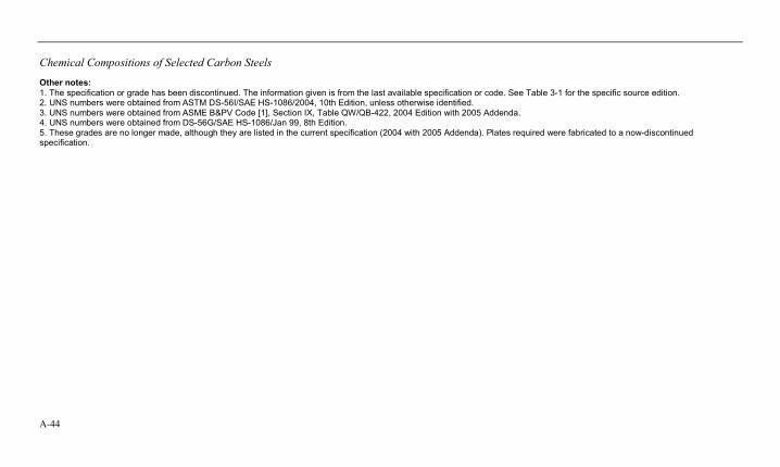
Chemical Compositions of Selected Carbon Steels
A-44
Other notes: 1. The specification or grade has been discontinued. The information given is from the last available specification or code. See Table 3-1 for the specific source edition. 2. UNS numbers were obtained from ASTM DS-56I/SAE HS-1086/2004, 10th Edition, unless otherwise identified. 3. UNS numbers were obtained from ASME B&PV Code [1], Section IX, Table QW/QB-422, 2004 Edition with 2005 Addenda. 4. UNS numbers were obtained from DS-56G/SAE HS-1086/Jan 99, 8th Edition. 5. These grades are no longer made, although they are listed in the current specification (2004 with 2005 Addenda). Plates required were fabricated to a now-discontinued specification.

B-1
B MECHANICAL PROPERTIES OF SELECTED CARBON STEELS
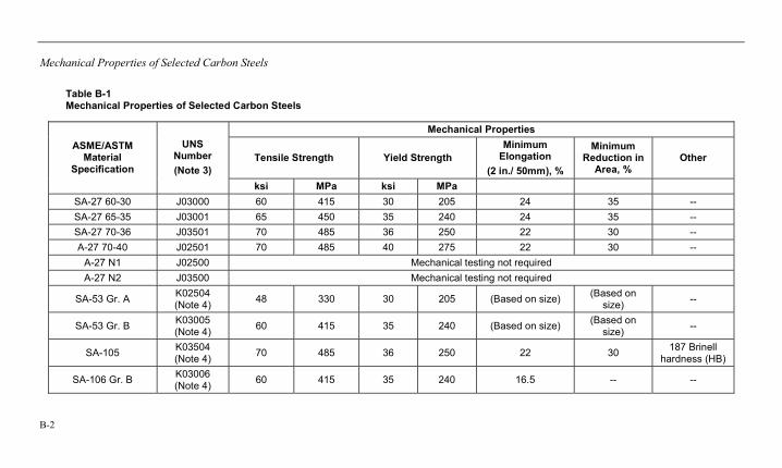
Mechanical Properties of Selected Carbon Steels
B-2
Table B-1 Mechanical Properties of Selected Carbon Steels
Mechanical Properties
Tensile Strength Yield Strength Minimum
Elongation (2 in./ 50mm), %
Minimum Reduction in
Area, % Other
ASME/ASTM Material
Specification
UNS Number (Note 3)
ksi MPa ksi MPa SA-27 60-30 J03000 60 415 30 205 24 35 -- SA-27 65-35 J03001 65 450 35 240 24 35 -- SA-27 70-36 J03501 70 485 36 250 22 30 -- A-27 70-40 J02501 70 485 40 275 22 30 --
A-27 N1 J02500 Mechanical testing not required A-27 N2 J03500 Mechanical testing not required
SA-53 Gr. A K02504 (Note 4) 48 330 30 205 (Based on size) (Based on
size) --
SA-53 Gr. B K03005 (Note 4) 60 415 35 240 (Based on size) (Based on
size) --
SA-105 K03504 (Note 4) 70 485 36 250 22 30 187 Brinell
hardness (HB)
SA-106 Gr. B K03006 (Note 4) 60 415 35 240 16.5 -- --
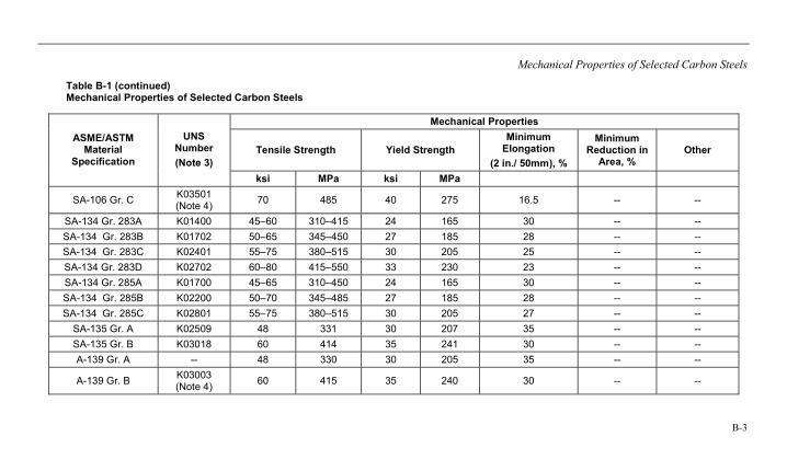
Mechanical Properties of Selected Carbon Steels
B-3
Table B-1 (continued) Mechanical Properties of Selected Carbon Steels
Mechanical Properties
Tensile Strength Yield Strength Minimum
Elongation (2 in./ 50mm), %
Minimum Reduction in
Area, % Other
ASME/ASTM Material
Specification
UNS Number (Note 3)
ksi MPa ksi MPa
SA-106 Gr. C K03501 (Note 4) 70 485 40 275 16.5 -- --
SA-134 Gr. 283A K01400 45–60 310–415 24 165 30 -- -- SA-134 Gr. 283B K01702 50–65 345–450 27 185 28 -- -- SA-134 Gr. 283C K02401 55–75 380–515 30 205 25 -- -- SA-134 Gr. 283D K02702 60–80 415–550 33 230 23 -- -- SA-134 Gr. 285A K01700 45–65 310–450 24 165 30 -- -- SA-134 Gr. 285B K02200 50–70 345–485 27 185 28 -- -- SA-134 Gr. 285C K02801 55–75 380–515 30 205 27 -- --
SA-135 Gr. A K02509 48 331 30 207 35 -- -- SA-135 Gr. B K03018 60 414 35 241 30 -- -- A-139 Gr. A -- 48 330 30 205 35 -- --
A-139 Gr. B K03003 (Note 4) 60 415 35 240 30 -- --
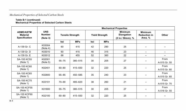
Mechanical Properties of Selected Carbon Steels
B-4
Table B-1 (continued) Mechanical Properties of Selected Carbon Steels
Mechanical Properties
Tensile Strength Yield Strength Minimum
Elongation (2 in./ 50mm), %
Minimum Reduction in
Area, % Other
ASME/ASTM Material
Specification
UNS Number (Note 3)
ksi MPa ksi MPa
A-139 Gr. C K03004 (Note 4) 60 415 42 290 25 -- --
A-139 Gr. D K03010 60 415 46 315 23 -- -- A-139 Gr. E K03012 66 455 52 360 22 -- --
SA-155 KC55 (Note 1)
K02001 (Note 5) 55–75 380–515 30 205 27 --
From A-515 Gr. 55
SA-155 KC60 (Note 1) K02401 60–80 415–550 32 220 25 --
From A-515 Gr. 60
SA-155 KC65 (Note 1) K02800 65–85 450–585 35 240 23 --
From A-515 Gr. 65
SA-155 KC70 (Note 1) K03101 70–90 485–620 38 260 21 --
From A-515 Gr. 70
SA-155 KCF55 (Note 1) K01800 55–75 380–515 30 205 27 --
From A-516 Gr. 55
SA-155 KCF60 (Note 1) K02100 60–80 415–550 32 220 25 -- --
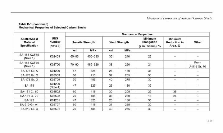
Mechanical Properties of Selected Carbon Steels
B-5
Table B-1 (continued) Mechanical Properties of Selected Carbon Steels
Mechanical Properties
Tensile Strength Yield Strength Minimum
Elongation (2 in./ 50mm), %
Minimum Reduction in
Area, % Other
ASME/ASTM Material
Specification
UNS Number (Note 3)
ksi MPa ksi MPa SA-155 KCF65
(Note 1) K02403 65–85 450–585 35 240 23 -- --
SA-155 KCF70 (Note 1) K02700 70–90 485–620 38 260 21 --
From A-516 Gr. 70
SA-178 Gr. A K01200 47 325 26 180 35 -- -- SA-178 Gr. C K03503 60 415 37 255 30 -- -- SA-178 Gr. D K02709 70 485 40 275 30 -- --
SA-179 K01200 (Note 4) 47 325 26 180 35 -- --
SA-181 Cl. 60 K03502 60 415 30 205 22 35 -- SA-181 Cl. 70 K03502 70 485 36 250 18 24 --
SA-192 K01201 47 325 26 180 35 -- -- SA-210 Gr. A1 K02707 60 415 37 255 30 -- -- SA-210 Gr. C K03501 70 485 40 275 30 -- --
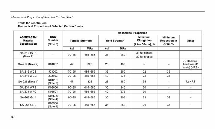
Mechanical Properties of Selected Carbon Steels
B-6
Table B-1 (continued) Mechanical Properties of Selected Carbon Steels
Mechanical Properties
Tensile Strength Yield Strength Minimum
Elongation (2 in./ 50mm), %
Minimum Reduction in
Area, % Other
ASME/ASTM Material
Specification
UNS Number (Note 3)
ksi MPa ksi MPa SA-212 Gr. B
(Note 1) -- 70–85 485–585 38 260 21 for flange; 22 for firebox
-- --
SA-214 (Note 2) K01807 47 325 26 180 -- -- 72 Rockwell hardness (B scale) (HRB)
SA-216 WCB J03002 70–95 485–655 36 250 22 35 -- SA-216 WCC J02503 70–95 485–655 40 275 22 35 --
SA-226 (Note 1) K01201 (Note 5) 47 325 26 180 35 -- 72 HRB
SA-234 WPB K03006 60–85 415–585 35 240 30 -- -- SA-234 WPC K03501 70–95 485–655 40 275 30 -- --
SA-266 Gr. 1 K03506 (Note 4) 60–85 415–585 30 205 23 38 --
SA-266 Gr. 2 K03506 (Note 4) 70–95 485–655 36 250 20 33 --
Mechanical Properties of Selected Carbon Steels
B-7
Table B-1 (continued) Mechanical Properties of Selected Carbon Steels
Mechanical Properties
Tensile Strength Yield Strength Minimum
Elongation (2 in./ 50mm), %
Minimum Reduction in
Area, % Other
ASME/ASTM Material
Specification
UNS Number (Note 3)
ksi MPa ksi MPa
SA-266 Gr. 3 K05001 (Note 4) 75–100 515 690 37.5 260 19 30
SA-266 Gr. 4 K03017 70–95 485–655 36 250 20 33 -- SA-283 Gr. A K01400 45–60 310–415 24 165 30 -- -- SA-283 Gr. B K01702 50–65 345–450 27 185 28 -- -- SA-283 Gr. C K02401 55–75 380–515 30 205 25 -- -- SA-283 Gr. D K02702 60–80 415–550 33 230 23 -- -- SA-285 Gr. A K01700 45–65 310–450 24 165 30 -- -- SA-285 Gr. B K02200 50–70 345–485 27 185 28 -- -- SA-285 Gr. C K02801 55–75 380–515 30 205 27 -- --
SA-299 K02803 75–95 515–655 42 ≤ 1 in. 40 > 1 in.
290 ≤ 1 in.
275 > 1 in.
19 -- --
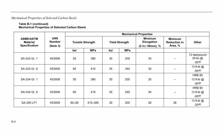
Mechanical Properties of Selected Carbon Steels
B-8
Table B-1 (continued) Mechanical Properties of Selected Carbon Steels
Mechanical Properties
Tensile Strength Yield Strength Minimum
Elongation (2 in./ 50mm), %
Minimum Reduction in
Area, % Other
ASME/ASTM Material
Specification
UNS Number (Note 3)
ksi MPa ksi MPa
SA-333 Gr. 1 K03008 55 380 30 205 35 -- 13 feet/pound
(ft-lb) @ -50ºF
SA-333 Gr. 6 K03006 60 415 35 240 30 -- 13 ft-lb @
-50ºF
SA-334 Gr. 1 K03008 55 380 30 205 35 -- HRB 85
13 ft-lb @ -50ºF
SA-334 Gr. 6 K03006 60 415 35 240 30 -- HRB 90
13 ft-lb @ -50ºF
SA-350 LF1 K03009 60–85 415–585 30 205 28 38 13 ft-lb @
-20ºF
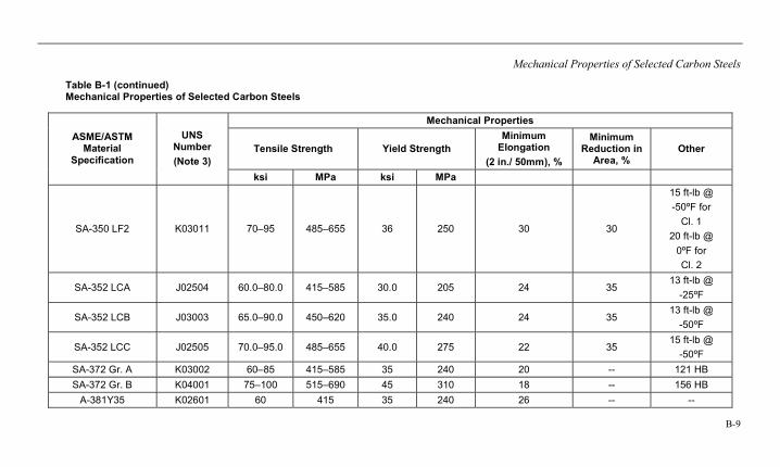
Mechanical Properties of Selected Carbon Steels
B-9
Table B-1 (continued) Mechanical Properties of Selected Carbon Steels
Mechanical Properties
Tensile Strength Yield Strength Minimum
Elongation (2 in./ 50mm), %
Minimum Reduction in
Area, % Other
ASME/ASTM Material
Specification
UNS Number (Note 3)
ksi MPa ksi MPa
SA-350 LF2 K03011 70–95 485–655 36 250 30 30
15 ft-lb @ -50ºF for
Cl. 1 20 ft-lb @
0ºF for Cl. 2
SA-352 LCA J02504 60.0–80.0 415–585 30.0 205 24 35 13 ft-lb @
-25ºF
SA-352 LCB J03003 65.0–90.0 450–620 35.0 240 24 35 13 ft-lb @
-50ºF
SA-352 LCC J02505 70.0–95.0 485–655 40.0 275 22 35 15 ft-lb @
-50ºF SA-372 Gr. A K03002 60–85 415–585 35 240 20 -- 121 HB SA-372 Gr. B K04001 75–100 515–690 45 310 18 -- 156 HB
A-381Y35 K02601 60 415 35 240 26 -- --
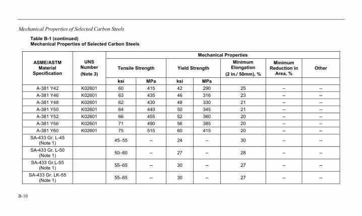
Mechanical Properties of Selected Carbon Steels
B-10
Table B-1 (continued) Mechanical Properties of Selected Carbon Steels
Mechanical Properties
Tensile Strength Yield Strength Minimum
Elongation (2 in./ 50mm), %
Minimum Reduction in
Area, % Other
ASME/ASTM Material
Specification
UNS Number (Note 3)
ksi MPa ksi MPa A-381 Y42 K02601 60 415 42 290 25 -- -- A-381 Y46 K02601 63 435 46 316 23 -- -- A-381 Y48 K02601 62 430 48 330 21 -- -- A-381 Y50 K02601 64 440 50 345 21 -- -- A-381 Y52 K02601 66 455 52 360 20 -- -- A-381 Y56 K02601 71 490 56 385 20 -- -- A-381 Y60 K02601 75 515 60 415 20 -- --
SA-433 Gr. L-45 (Note 1) 45–55 -- 24 -- 30 -- --
SA-433 Gr. L-50 (Note 1) 50–60 -- 27 -- 28 -- --
SA-433 Gr.L-55 (Note 1) 55–65 -- 30 -- 27 -- --
SA-433 Gr. LK-55 (Note 1) 55–65 -- 30 -- 27 -- --
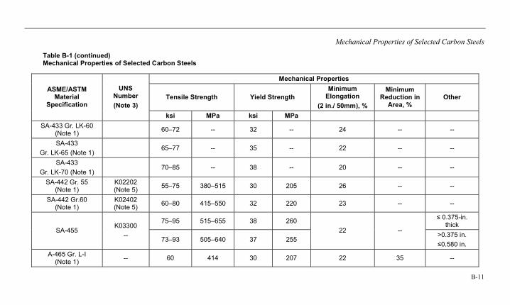
Mechanical Properties of Selected Carbon Steels
B-11
Table B-1 (continued) Mechanical Properties of Selected Carbon Steels
Mechanical Properties
Tensile Strength Yield Strength Minimum
Elongation (2 in./ 50mm), %
Minimum Reduction in
Area, % Other
ASME/ASTM Material
Specification
UNS Number (Note 3)
ksi MPa ksi MPa SA-433 Gr. LK-60
(Note 1) 60–72 -- 32 -- 24 -- --
SA-433 Gr. LK-65 (Note 1)
65–77 -- 35 -- 22 -- --
SA-433 Gr. LK-70 (Note 1)
70–85 -- 38 -- 20 -- --
SA-442 Gr. 55 (Note 1)
K02202 (Note 5) 55–75 380–515 30 205 26 -- --
SA-442 Gr.60 (Note 1)
K02402 (Note 5) 60–80 415–550 32 220 23 -- --
75–95 515–655 38 260 ≤ 0.375-in. thick
SA-455 K03300
-- 73–93 505–640 37 255 22 -- >0.375 in.
≤0.580 in. A-465 Gr. L-I
(Note 1) -- 60 414 30 207 22 35 --
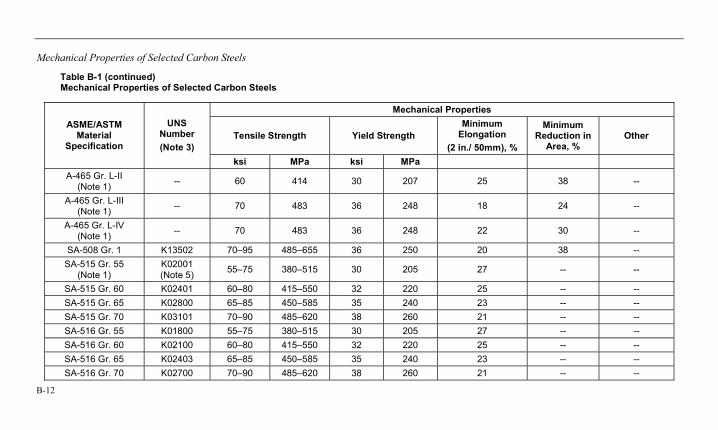
Mechanical Properties of Selected Carbon Steels
B-12
Table B-1 (continued) Mechanical Properties of Selected Carbon Steels
Mechanical Properties
Tensile Strength Yield Strength Minimum
Elongation (2 in./ 50mm), %
Minimum Reduction in
Area, % Other
ASME/ASTM Material
Specification
UNS Number (Note 3)
ksi MPa ksi MPa A-465 Gr. L-II
(Note 1) -- 60 414 30 207 25 38 --
A-465 Gr. L-III (Note 1) -- 70 483 36 248 18 24 --
A-465 Gr. L-IV (Note 1) -- 70 483 36 248 22 30 --
SA-508 Gr. 1 K13502 70–95 485–655 36 250 20 38 -- SA-515 Gr. 55
(Note 1) K02001 (Note 5) 55–75 380–515 30 205 27 -- --
SA-515 Gr. 60 K02401 60–80 415–550 32 220 25 -- -- SA-515 Gr. 65 K02800 65–85 450–585 35 240 23 -- -- SA-515 Gr. 70 K03101 70–90 485–620 38 260 21 -- -- SA-516 Gr. 55 K01800 55–75 380–515 30 205 27 -- -- SA-516 Gr. 60 K02100 60–80 415–550 32 220 25 -- -- SA-516 Gr. 65 K02403 65–85 450–585 35 240 23 -- -- SA-516 Gr. 70 K02700 70–90 485–620 38 260 21 -- --
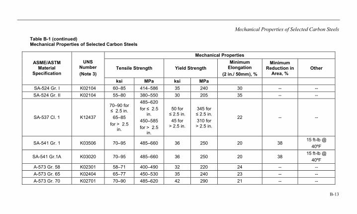
Mechanical Properties of Selected Carbon Steels
B-13
Table B-1 (continued) Mechanical Properties of Selected Carbon Steels
Mechanical Properties
Tensile Strength Yield Strength Minimum
Elongation (2 in./ 50mm), %
Minimum Reduction in
Area, % Other
ASME/ASTM Material
Specification
UNS Number (Note 3)
ksi MPa ksi MPa SA-524 Gr. I K02104 60–85 414–586 35 240 30 -- -- SA-524 Gr. II K02104 55–80 380–550 30 205 35 -- --
SA-537 Cl. 1 K12437
70–90 for ≤ 2.5 in. 65–85
for > 2.5 in.
485–620 for ≤ 2.5
in. 450–585 for > 2.5
in.
50 for ≤ 2.5 in. 45 for
> 2.5 in.
345 for ≤ 2.5 in. 310 for > 2.5 in.
22 -- --
SA-541 Gr. 1 K03506 70–95 485–660 36 250 20 38 15 ft-lb @
40ºF
SA-541 Gr.1A K03020 70–95 485–660 36 250 20 38 15 ft-lb @
40ºF A-573 Gr. 58 K02301 58–71 400–490 32 220 24 -- -- A-573 Gr. 65 K02404 65–77 450–530 35 240 23 -- -- A-573 Gr. 70 K02701 70–90 485–620 42 290 21 -- --
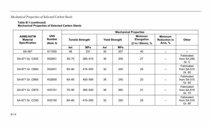
Mechanical Properties of Selected Carbon Steels
B-14
Table B-1 (continued) Mechanical Properties of Selected Carbon Steels
Mechanical Properties
Tensile Strength Yield Strength Minimum
Elongation (2 in./ 50mm), %
Minimum Reduction in
Area, % Other
ASME/ASTM Material
Specification
UNS Number (Note 3)
ksi MPa ksi MPa SA-587 K11500 48 331 30 207 40 -- --
SA-671 Gr. CA55 K02801 55–75 380–515 30 205 27 -- Fabricated
from SA-285 Gr. C
SA-671 Gr. CB60 K02401 60–80 415–550 32 220 25 -- Fabricated
from SA-515 Gr. 60
SA-671 Gr. CB65 K02800 65–85 450–585 35 240 23 -- Fabricated
from SA-515 Gr. 65
SA-671 Gr. CB70 K03101 70–90 485–620 38 260 21 -- Fabricated
from SA-515 Gr. 70
SA-671 Gr. CC60 K02100 60–80 415–550 32 220 25 -- Fabricated
from SA-516 Gr. 60
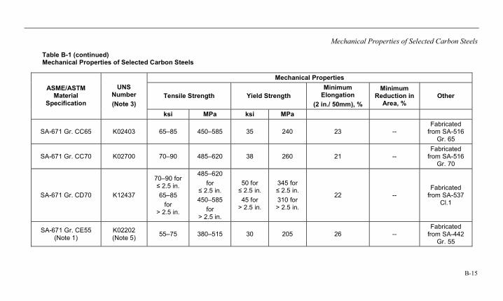
Mechanical Properties of Selected Carbon Steels
B-15
Table B-1 (continued) Mechanical Properties of Selected Carbon Steels
Mechanical Properties
Tensile Strength Yield Strength Minimum
Elongation (2 in./ 50mm), %
Minimum Reduction in
Area, % Other
ASME/ASTM Material
Specification
UNS Number (Note 3)
ksi MPa ksi MPa
SA-671 Gr. CC65 K02403 65–85 450–585 35 240 23 -- Fabricated
from SA-516 Gr. 65
SA-671 Gr. CC70 K02700 70–90 485–620 38 260 21 -- Fabricated
from SA-516 Gr. 70
SA-671 Gr. CD70 K12437
70–90 for ≤ 2.5 in. 65–85
for > 2.5 in.
485–620 for
≤ 2.5 in. 450–585
for > 2.5 in.
50 for ≤ 2.5 in. 45 for
> 2.5 in.
345 for ≤ 2.5 in. 310 for > 2.5 in.
22 -- Fabricated
from SA-537 Cl.1
SA-671 Gr. CE55 (Note 1)
K02202 (Note 5) 55–75 380–515 30 205 26 --
Fabricated from SA-442
Gr. 55
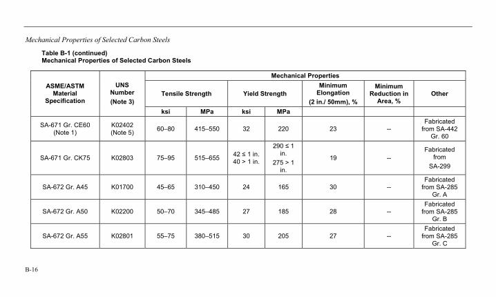
Mechanical Properties of Selected Carbon Steels
B-16
Table B-1 (continued) Mechanical Properties of Selected Carbon Steels
Mechanical Properties
Tensile Strength Yield Strength Minimum
Elongation (2 in./ 50mm), %
Minimum Reduction in
Area, % Other
ASME/ASTM Material
Specification
UNS Number (Note 3)
ksi MPa ksi MPa
SA-671 Gr. CE60 (Note 1)
K02402 (Note 5) 60–80 415–550 32 220 23 --
Fabricated from SA-442
Gr. 60
SA-671 Gr. CK75 K02803 75–95 515–655 42 ≤ 1 in. 40 > 1 in.
290 ≤ 1 in.
275 > 1 in.
19 -- Fabricated
from SA-299
SA-672 Gr. A45 K01700 45–65 310–450 24 165 30 -- Fabricated
from SA-285 Gr. A
SA-672 Gr. A50 K02200 50–70 345–485 27 185 28 -- Fabricated
from SA-285 Gr. B
SA-672 Gr. A55 K02801 55–75 380–515 30 205 27 -- Fabricated
from SA-285 Gr. C
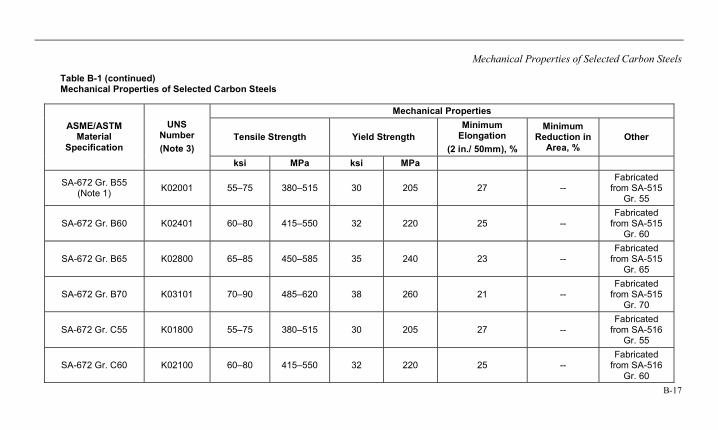
Mechanical Properties of Selected Carbon Steels
B-17
Table B-1 (continued) Mechanical Properties of Selected Carbon Steels
Mechanical Properties
Tensile Strength Yield Strength Minimum
Elongation (2 in./ 50mm), %
Minimum Reduction in
Area, % Other
ASME/ASTM Material
Specification
UNS Number (Note 3)
ksi MPa ksi MPa
SA-672 Gr. B55 (Note 1) K02001 55–75 380–515 30 205 27 --
Fabricated from SA-515
Gr. 55
SA-672 Gr. B60 K02401 60–80 415–550 32 220 25 -- Fabricated
from SA-515 Gr. 60
SA-672 Gr. B65 K02800 65–85 450–585 35 240 23 -- Fabricated
from SA-515 Gr. 65
SA-672 Gr. B70 K03101 70–90 485–620 38 260 21 -- Fabricated
from SA-515 Gr. 70
SA-672 Gr. C55 K01800 55–75 380–515 30 205 27 -- Fabricated
from SA-516 Gr. 55
SA-672 Gr. C60 K02100 60–80 415–550 32 220 25 -- Fabricated
from SA-516 Gr. 60
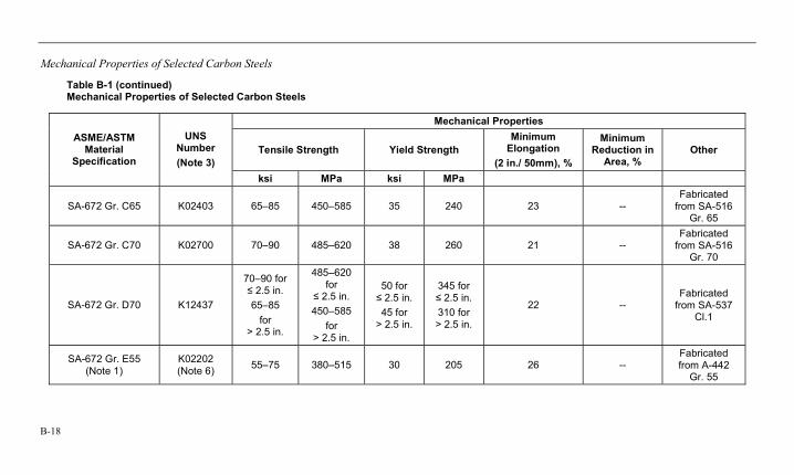
Mechanical Properties of Selected Carbon Steels
B-18
Table B-1 (continued) Mechanical Properties of Selected Carbon Steels
Mechanical Properties
Tensile Strength Yield Strength Minimum
Elongation (2 in./ 50mm), %
Minimum Reduction in
Area, % Other
ASME/ASTM Material
Specification
UNS Number (Note 3)
ksi MPa ksi MPa
SA-672 Gr. C65 K02403 65–85 450–585 35 240 23 -- Fabricated
from SA-516 Gr. 65
SA-672 Gr. C70 K02700 70–90 485–620 38 260 21 -- Fabricated
from SA-516 Gr. 70
SA-672 Gr. D70 K12437
70–90 for ≤ 2.5 in. 65–85
for > 2.5 in.
485–620 for
≤ 2.5 in. 450–585
for > 2.5 in.
50 for ≤ 2.5 in. 45 for
> 2.5 in.
345 for ≤ 2.5 in. 310 for > 2.5 in.
22 -- Fabricated
from SA-537 Cl.1
SA-672 Gr. E55 (Note 1)
K02202 (Note 6) 55–75 380–515 30 205 26 --
Fabricated from A-442
Gr. 55
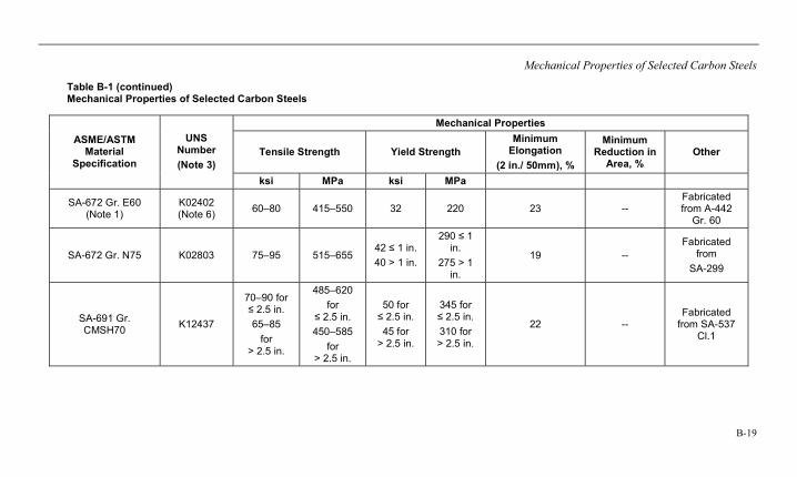
Mechanical Properties of Selected Carbon Steels
B-19
Table B-1 (continued) Mechanical Properties of Selected Carbon Steels
Mechanical Properties
Tensile Strength Yield Strength Minimum
Elongation (2 in./ 50mm), %
Minimum Reduction in
Area, % Other
ASME/ASTM Material
Specification
UNS Number (Note 3)
ksi MPa ksi MPa
SA-672 Gr. E60 (Note 1)
K02402 (Note 6) 60–80 415–550 32 220 23 --
Fabricated from A-442
Gr. 60
SA-672 Gr. N75 K02803 75–95 515–655 42 ≤ 1 in. 40 > 1 in.
290 ≤ 1 in.
275 > 1 in.
19 -- Fabricated
from SA-299
SA-691 Gr. CMSH70 K12437
70–90 for ≤ 2.5 in. 65–85
for > 2.5 in.
485–620 for
≤ 2.5 in. 450–585
for > 2.5 in.
50 for ≤ 2.5 in. 45 for
> 2.5 in.
345 for ≤ 2.5 in. 310 for > 2.5 in.
22 -- Fabricated
from SA-537 Cl.1
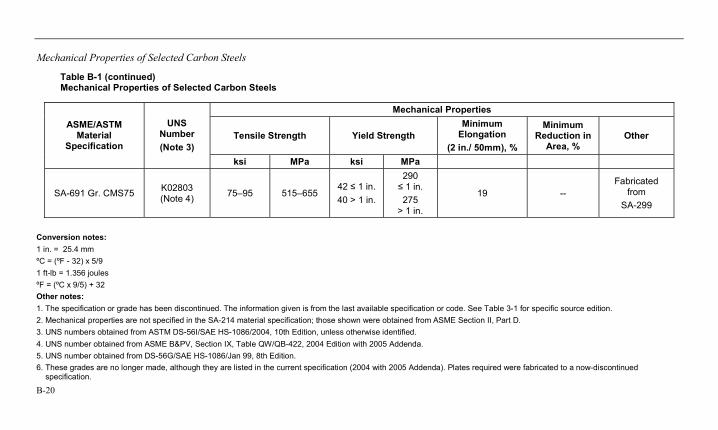
Mechanical Properties of Selected Carbon Steels
B-20
Table B-1 (continued) Mechanical Properties of Selected Carbon Steels
Mechanical Properties
Tensile Strength Yield Strength Minimum
Elongation (2 in./ 50mm), %
Minimum Reduction in
Area, % Other
ASME/ASTM Material
Specification
UNS Number (Note 3)
ksi MPa ksi MPa
SA-691 Gr. CMS75 K02803 (Note 4) 75–95 515–655
42 ≤ 1 in. 40 > 1 in.
290 ≤ 1 in. 275
> 1 in.
19 -- Fabricated
from SA-299
Conversion notes: 1 in. = 25.4 mm ºC = (ºF - 32) x 5/9 1 ft-lb = 1.356 joules ºF = (ºC x 9/5) + 32 Other notes: 1. The specification or grade has been discontinued. The information given is from the last available specification or code. See Table 3-1 for specific source edition. 2. Mechanical properties are not specified in the SA-214 material specification; those shown were obtained from ASME Section II, Part D. 3. UNS numbers obtained from ASTM DS-56I/SAE HS-1086/2004, 10th Edition, unless otherwise identified. 4. UNS number obtained from ASME B&PV, Section IX, Table QW/QB-422, 2004 Edition with 2005 Addenda. 5. UNS number obtained from DS-56G/SAE HS-1086/Jan 99, 8th Edition. 6. These grades are no longer made, although they are listed in the current specification (2004 with 2005 Addenda). Plates required were fabricated to a now-discontinued specification.

Export Control RestrictionsAccess to and use of EPRI Intellectual Property is granted with the specific un-derstanding and requirement that respon-sibility for ensuring full compliance with all applicable U.S. and foreign export laws and regulations is being undertaken by you and your company. This includes an obligation to ensure that any individual receiving access hereunder who is not a U.S. citizen or permanent U.S. resident is permitted access under applicable U.S. and foreign export laws and regulations. In the event you are uncertain whether you or your company may lawfully obtain ac-cess to this EPRI Intellectual Property, you acknowledge that it is your obligation to consult with your company’s legal counsel to determine whether this access is lawful. Although EPRI may make available on a case-by-case basis an informal assessment of the applicable U.S. export classification for specific EPRI Intellectual Property, you and your company acknowledge that this assessment is solely for informational pur-poses and not for reliance purposes. You and your company acknowledge that it is still the obligation of you and your com-pany to make your own assessment of the applicable U.S. export classification and ensure compliance accordingly. You and your company understand and acknowl-edge your obligations to make a prompt report to EPRI and the appropriate authori-ties regarding any access to or use of EPRI Intellectual Property hereunder that may be in violation of applicable U.S. or foreign export laws or regulations.
Electric Power Research Institute 3420 Hillview Avenue, Palo Alto, California 94304-1338 PO Box 10412, Palo Alto, California 94303-0813 USA
800.313.3774 • 650.855.2121 • [email protected] • www.epri.com
The Electric Power Research Institute (EPRI), with major locations in Palo Alto, California; Charlotte, North Carolina; and Knoxville, Tennessee, was established in 1973 as an independent, nonprofit center for public interest energy and environmental research. EPRI brings together members, participants, the Institute’s scientists and engineers, and other leading experts to work collaboratively on solutions to the challenges of electric power. These solutions span nearly every area of electricity generation, delivery, and use, including health, safety, and environment. EPRI’s members represent over 90% of the electricity generated in the United States. International participation represents nearly 15% of EPRI’s total research, development, and demonstration program.
Together...Shaping the Future of Electricity
Program:
Fossil Materials and Repair
1014670
© 2007 Electric Power Research Institute (EPRI), Inc. All rights reserved. Electric Power Research Institute, EPRI, and TOGETHER...SHAPING THE FUTURE OF ELECTRICITY are registered service marks of the Electric Power Research Institute, Inc.
PrintedonrecycledpaperintheUnitedStatesofAmerica