cardax ft connectivity guide - samer · pdf file · 2013-08-15cardax ft...
TRANSCRIPT

Page 1 1 November 2010
Cardax FT Connectivity Guide

Page 2 1 November 2010
Introduction ......................................................................................................... 3
Cardax FT System .............................................................................................. 4 Introduction ..................................................................................................... 4 Hardware communication ............................................................................... 4 System Architecture ........................................................................................ 5 Building Blocks ................................................................................................ 7
Cardax FT Controller 3000 .......................................................................... 8 Cardax FT Controller 5000GL ..................................................................... 9 Cardax FT Command Centre .................................................................... 12
Controller to Field Device Communications .................................................. 12 Termination of Field Device communications cables ................................. 12
Controller to Cardax FT Command Centre Communications ........................ 12
Cardax FT Components ................................................................................... 13
Networking and Communications ..................................................................... 19 Controller to Field Item Connections ............................................................. 19
Communication ports ................................................................................. 19 Cabling ...................................................................................................... 21
High-Level Ethernet Connections ................................................................. 22 Workstation to Server Communications ........................................................ 23 Modem Access to Controllers ....................................................................... 23
Traditional Dial-Up ..................................................................................... 25 Dial-up Via the Internet .............................................................................. 25 Common Properties of Dial-Up Controllers ............................................... 25 Comparison of the Two Options ................................................................ 26
Diverse Communications Routes ..................................................................... 27 Communications Loop .................................................................................. 28 Dual Redundant Connection to an Existing Switched Network ..................... 29
Monitoring the network .............................................................................. 30
Biometric Identification...................................................................................... 31
Disclaimer ......................................................................................................... 32

Page 3 1 November 2010
Introduction
This document was prepared for independent consultants, system engineers, security industry specialists and Cardax distributors. Its purpose is to assist in the planning and upgrading of Cardax security networks. Cardax FT security systems are groups of microprocessor based units which are configured for access control and security monitoring. The processing power of a Cardax FT system is distributed throughout the system’s components making Cardax FT an ideal solution to control and monitor geographically distributed buildings and facilities.

Page 4 1 November 2010
Cardax FT System
INTRODUCTION Cardax FT is the platform for the new generation of access control and security systems from Cardax. Cardax FT is a comprehensive Microsoft® Windows® based security system that integrates access control and alarm management. Features of a Cardax FT system can include:
• access control;
• alarm monitoring;
• alarm management;
• photo identification;
• voice communication (intercom);
• PowerFence™ perimeter control and monitoring;
• Visitor management;
• security photography, encompassing- • closed circuit television (CCTV); and • Integrated digital video recording (DVR).
HARDWARE COMMUNICATION Communication between Cardax FT Controllers and lower level hardware items uses two Cardax-proprietary data communication formats. These are: RS-485 The RS-485 transmission scheme uses asynchronous half duplex
communication. Each RS-485 circuit may be configured to operate to support any of the following functions:
• GBUS. Communication between Cardax FT Controllers and Cardax FT
sub-units. The data rate is 38.4kbits/second. • APERIO. Communication between Cardax FT Controller units and Aperio
readers is 19.2kbits/second. • SENSOR. Communication between Cardax FT Controller 6000 units and
Disturbance or Tautwire Sensors is 115.2kbits/second.
LOCAL BUS Data rate is 187.5 kbits/second. The transmission scheme is RS-485 synchronous, half duplex. This format is now a legacy format and not recommended for new installations.
RS-232 Serial Communications used for Dialler plug-on connectivity The terms “GBUS”, “LOCAL BUS”, and “RS-232” are used throughout this document.

Page 5 1 November 2010
SYSTEM ARCHITECTURE
Continued over..........

Page 6 1 November 2010
A Cardax FT system may consist of a variety of system components. These components are grouped into a hierarchy that determines the communications methodology and interconnection options. Components at Level 2 communicate with Cardax FT Controller 3000, Cardax FT Controller 5000GL or Cardax FT Controller 6000 at Level 3. Note that the Cardax FT IDT (LOCAL BUS) reader is a Level 2 component. Communications between Levels 2 and 3 use a low level protocol. The level 3 Cardax FT Controller 3000, Controller 5000GL and Controller 6000 communicate with the Level 4 Cardax FT Command Centre using a high level protocol. These protocols are described later in this document.

Page 7 1 November 2010
In effect, the Cardax FT Controller 3000 and Cardax FT Controller 6000 with reader module fitted, span Levels 2 and 3. Devices at Level 1 can communicate with the Cardax FT GBUS Universal Reader Interface, or the Cardax FT Controller 3000. The Cardax protocols have been chosen for the following reasons.
• To facilitate the large-scale interconnection of Cardax devices and thus permit the construction of large networks.
• To ensure high security and enhance the resistance of the system to attack.
• To efficiently transport information.
BUILDING BLOCKS The Cardax FT system supports three types of intelligent field controller called Cardax FT Controller 3000, Cardax FT Controller 5000GL and Cardax FT 6000. Peripheral hardware, called field devices, may be connected to the controllers. Not all field devices are compatible with both types of controller. The controllers and field devices are managed by Cardax FT Command Centre. Controllers communicate with field devices using a scheme specific to the type of controller. Controllers communicate with each other and with Cardax FT Command Centre using the Transmission Control Protocol and Internet Protocol (TCP/IP) over Ethernet.

Page 8 1 November 2010
Cardax FT Controller 3000 The Cardax FT Controller 3000 incorporates inputs and outputs and directly supports some types of Cardax and third-party door readers. Field devices specific to this controller use the RS-485 port configured to operate either as GBUS or APERIO ports. GBUS Devices
• Cardax FT Remote Arming Terminal
• Cardax FT Controller 3000 input/output/reader expansion boards: o 8-Input Expansion o I/O Expansion (8-input, 4-output) o High Density I/O Expansion (16-input, 16-output) o Cardax FT GBUS Universal Reader Interface o Cardax FT GBUS Wiegand Universal Reader Interface
• PowerFence Trophy FT Fence Controller
• PowerFence Trophy FT Keypad
• Cardax FT Dialler (RS-232 plug on-board) The Cardax FT Controller 3000 RS-485 port can communicate via GBUS with up to:
• eight input/output/reader expansion boards, PLUS
• four Cardax FT Remote Arming Terminals or PowerFence Trophy FT Keypads, PLUS
• sixteen PowerFence Trophy FT Fence Controllers, PLUS
• one Cardax FT Dialler.
APERIO Devices
• Door escutcheons
• Lock cylinders Connectivity recommendations: While the connectivity of the Controller 3000 allows for up to 24 doors to be physically connected via expansion boards, Cardax FT Controller 3000 is designed to manage 8 doors. This may be equated to 2 access control transactions per second. Where a high transaction load is placed on a Controller 3000, the number of field devices that can be attached to the Controller may reduce from the maximum listed above. Contact your GSMS technical representative prior to exceeding these recommendations.

Page 9 1 November 2010
Cardax FT Controller 5000GL The Controller 5000GL supports two RS-485 communications ports; one port configured for GBUS or APERIO devices, and one user configurable port to support either GBUS/APERIO devices or for LOCAL BUS devices. Field devices specific to this controller may be either GBUS, APERIO or LOCAL BUS devices as detailed below: GBUS Devices
• 8-Input Expansion • I/O Expansion (8-input, 4-output)
• High Density I/O Expansion (16-input, 16-output)
• Cardax FT GBUS Universal Reader Interface
• Cardax FT Remote Arming Terminal
• PowerFence Trophy FT Keypad
• PowerFence Trophy FT Fence Controller Each RS-485 port/run can support via GBUS, up to a maximum of:
• 8 GBUS I/O devices (8-input / I/O Expansion / High Density I/O Expansion / GBUS URI), PLUS
• 4 Cardax FT Remote Arming Terminals or PowerFence Trophy FT Keypads, PLUS
• 16 PowerFence Trophy FT Fence Controllers
APERIO Devices
• Door escutcheons
• Lock cylinders LOCAL BUS Devices
• Cardax FT Intelligent Door Terminals:
• Cardax FT IDT (Mifare Series) • Cardax FT IDT (TIRIS Series) • Cardax FT IDT (125 Series)
The LOCAL BUS port supports two channels allowing physical wiring to split into two physical LOCAL BUS runs. The Cardax FT Controller 5000GL can communicate with up to 16 LOCAL BUS field devices.

Page 10 1 November 2010
Cardax FT Intelligent Door Terminals each incorporate an intercom, which communicates over the same integrated protocol/wiring as the reader communications. The Controller 5000GL also supports the Cardax FT Dialler 5000GL (Direct plug on-board) Connectivity recommendations: While the connectivity of the Controller 5000GL allows for up to 144 doors to be physically connected via expansion boards, Cardax FT Controller 5000GL is designed to manage 8 doors. This may be equated to 2 access control transactions per second. Where a high transaction load is placed on a Controller 5000GL, the number of field devices that can be attached to the Controller may reduce from the maximum listed above. Please contact your GSMS technical representative prior to exceeding any of the following:
• More than one access transaction per second per Controller
• More than 8 doors per Controller
• More than 8 Fence Controllers per Controller
• More than one Controller’s Alarm/Fence Zones associated to a single Remote Arming Terminal / PowerFence Trophy FT Keypad
Cardax FT Controller 6000 The Controller 6000 consists of two units; the controller and the reader module. The controller supports two RS-485 communications ports, each may be configured for either GBUS, APERIO or SENSOR communications: GBUS Devices
• 8-Input Expansion • I/O Expansion (8-input, 4-output)
• High Density I/O Expansion (16-input, 16-output)
• Cardax FT GBUS Universal Reader Interface
• Cardax FT GBUS Wiegand Universal Reader Interface
• Cardax FT Remote Arming Terminal
• PowerFence Trophy FT Keypad
• PowerFence Trophy FT Fence Controller Each GBUS configured port/run can support up to a maximum of:
• 8 GBUS I/O devices (8-input / I/O Expansion / High Density I/O Expansion / GBUS URI), PLUS
• 4 Cardax FT Remote Arming Terminals or PowerFence Trophy FT Keypads, PLUS
• 16 PowerFence Trophy FT Fence Controllers

Page 11 1 November 2010
APERIO Devices
• Door escutcheons
• Lock cylinders SENSOR Devices
• D10 Tautwire sensors
• D21 Disturbance Sensors
• N16 Connector Board
• Each RS-485 port configured for APERIO can support up to 8 APERIO devices. The Controller 6000 also supports the Cardax FT Dialler 3000 (RS-232 plug-on board). Connectivity recommendations: While the connectivity of the Controller 6000 allows a large number of doors to be physically connected via expansion boards, it is designed to manage 10 doors. This may be equated to 2 access control transactions per second. Where a high transaction load is placed on a Controller 6000, the number of field devices that can be attached to the Controller may reduce from the maximum listed above. Please contact your GSMS technical representative prior to exceeding any of the following:
• More than one access transaction per second per Controller
• More than 8 doors per Controller
• More than 8 Fence Controllers per Controller
• More than one Controller’s Alarm/Fence Zones associated to a single Remote Arming Terminal / PowerFence Trophy FT Keypad

Page 12 1 November 2010
Cardax FT Command Centre Cardax FT Command Centre server is the central computer. It runs on an INTEL server computer under a Microsoft® Windows operating system. The server is a collection of background services surrounding a database. Cardax FT Command Centre server records events and manages controllers and their associated field items. Cardax FT Command Centre server communicates with Cardax FT Command Centre workstations as well as controllers. The Cardax FT Command Centre workstation is the user interface. It enables an operator to set up cardholder access and site items and to view and manipulate the presentation of recorded events. A Cardax FT Command Centre workstation may reside on the same computer as the Cardax FT Command Centre server or it may be located on a computer distant from the server. Several Cardax FT Command Centre workstations can be linked to a Cardax FT Command Centre server over local area and wide area networks. This permits operators at diverse sites to monitor or configure a Cardax FT system.
CONTROLLER TO FIELD DEVICE COMMUNICATIONS The Cardax FT Controller 3000, Cardax FT Controller 5000GL and Cardax FT Controller 6000 communicate with field devices. The low-level transmission scheme used to communicate with field devices differs depending on the type of controller. The transmission protocols are referred to as GBUS and LOCAL BUS, and are proprietary to Gallagher Security Management Systems. Cardax FT Controller 3000 can be direct-wired for door monitoring and control, thus for some installations low-level RS-485 communications are not needed. Cardax FT Controller 5000GL always requires low-level RS-485 communications for door monitoring and control. Cardax FT Controller 6000 requires low-level RS-485 communications for door monitoring and control, as well as direct connection via the plug-in Cardax FT Controller 6000 reader Module.
Termination of Field Device communications cables In the Cardax FT system, connections to Field Devices are daisy-chained. Each Field Device bridges the communications cable at high impedance. To ensure the cable is correctly terminated, a resistor is connected across the communications ports of the Field Devices or controller at each end of the communication cable.
CONTROLLER TO CARDAX FT COMMAND CENTRE COMMUNICATIONS Controllers communicate with each other and with Cardax FT Command Centre either by:
• Transmission Control Protocol/Internet Protocol (TCP/IP) over Ethernet; or
• By means of a modem (Cardax FT Dialler or Cardax FT Dialler 5000GL).

Page 13 1 November 2010
Cardax FT Components
The following table summarises some characteristics of Cardax FT system components. Cardax FT Controllers
Component Makes
Decisions Polling Readers Inputs Outputs LOCAL
BUS RS485 Comments
Cardax FT Command Centre
Yes - - - - - - The operator makes site management decisions; the server makes system management decisions.
The server is the background application. The workstation is the graphical user interface.
Cardax FT Controller 3000-8R
Yes Polls Level 2 GBUS components.
8 Cardax IV readers, or 4 Weigand readers
16 8 - 1 Port Supports 8 doors with a maximum of eight Cardax readers or four Wiegand readers.
One RJ45 port for connection to an Ethernet high-level network using 10BaseT cabling.
One RS-485 low-level port for Level 2 communication via:
• GBUS. • APERIO
One RS232 port for communication with a Cardax FT Dialler.
Cardax FT Controller 3000-4R
Yes Polls Level 2 GBUS components.
4 Cardax IV readers, or 2 Weigand readers
8 4 - 1 Port Supports 8 doors with a maximum of four Cardax readers or two Wiegand readers.
One 10BaseT port for connection to an Ethernet high-level network.
One RS-485 low-level ports for Level 2 communication via:
• GBUS. • APERIO
One RS232 port for communication with a Cardax FT Dialler.

Page 14 1 November 2010
Component Makes
Decisions Polling Readers Inputs Outputs LOCAL
BUS GBUS Comments
Cardax FT Controller 5000GL
Yes Polls Level 2 GBUS and LOCAL BUS components.
- 4 1 1 Port or
0 Ports if 2 GBUS ports required
1 Port or
2 Ports if LOCAL BUS not required
Supports 8 doors via LOCAL BUS or GBUS level 2 devices.
One RJ45 port for connection to an Ethernet high-level network using 10BaseT cabling.
One RS-485 low-level port for Level 2 communication via:
• GBUS. • APERIO
One RS-485 low-level port for communication with Level 2 LOCAL BUS site items. Optionally the port can be configured as a second RS-485 port for GBUS or APERIO communication.
One dedicated port for communication with a Cardax FT Dialler 5000GL.
Cardax FT Controller 6000 Control module
Yes Polls Level 2 GBUS
- - - - 2 Supports 10 doors via Controller 6000 Reader Module or GBUS level 2 devices.
RJ45 connection to an Ethernet high-level network
Standard -1 x 10/100BaseT port
High Spec. – 2 x 10/100/1000BaseT ports
Two RS-485 low-level ports for Level 2 communication via:
• GBUS. • APERIO • SENSOR
One dedicated port for communication with a Cardax FT Dialler.
One USB port for on-site system setup and updates.
One interface connection to connect to one Cardax FT Controller 6000 Reader Module.
One In Service relay (HS version only)
Can operate without the Reader Module

Page 15 1 November 2010
Component Makes
Decisions Polling Readers Inputs Outputs LOCAL
BUS GBUS Comments
Cardax FT Controller 6000-4R Reader Module
No - 4 Cardax IV readers or 2 Wiegand readers
12 4 - - Provides input, output and reader connectivity for the Control module
Cardax FT Controller 6000-8R Reader Module
No - 8 Cardax IV readers or 4 Wiegand readers
24 8 - - Provides input, output and reader connectivity for the Control module
Cardax FT Dialler Devices
Component Makes
Decisions Polling Readers Inputs Outputs Comments
Cardax FT Dialler 3000
No - - - - Used for dial-up access between Cardax FT Controller 3000, Cardax FT Controller 6000 and Cardax FT Command Centre, or for the transmission of Ademco Contact ID messages from these Controllers to a 3rd party monitoring station.
One RS232 port for communication with a Cardax FT Controller 3000 of Cardax FT Controller 6000.
Cardax FT Dialler 5000GL
No - - - - Used for dial-up access between Cardax FT Controller 5000GL and Cardax FT Command Centre, or for the transmission of Ademco Contact ID messages from Cardax FT Controller 5000GL to a 3rd party monitoring station.
Connectivity for communication with a Cardax FT Controller 5000GL.
(Continued)

Page 16 1 November 2010
Cardax FT GBUS Devices
Component Makes Decisions
Polling Readers Inputs Outputs Comments
Cardax FT 8-Input Expansion
No Polled by the controller.
- 8 - One RS-485 low-level port for communication with a Cardax FT Controller 3000, Cardax FT Controller 5000GL or a Cardax FT Controller 6000 via the GBUS protocol.
Cardax FT I/O Expansion
No Polled by the controller.
- 8 4 One RS-485 low-level port for communication with a Cardax FT Controller 3000, Cardax FT Controller 5000GL or a Cardax FT Controller 6000 via the GBUS protocol.
Cardax FT High Density I/O Expansion
No Polled by the controller.
- 16 16 One RS-485 low-level port for communication with a Cardax FT Controller 3000, Cardax FT Controller 5000GL or a Cardax FT Controller 6000 via the GBUS protocol.
Cardax FT GBUS URI
No Polled by the controller.
2 Cardax IV readers, or 1 Weigand reader
8 2 One RS-485 low-level port for communication with a Cardax FT Controller 3000, Cardax FT Controller 5000GL or a Cardax FT Controller 6000 via the GBUS protocol.
Cardax FT GBUS Wiegand URI
No Polled by the controller.
2 Weigand readers
4 2 One RS-485 low-level port for communication with a Cardax FT Controller 3000, Cardax FT Controller 5000GL or a Cardax FT Controller 6000 via the GBUS protocol.
Cardax FT Remote Arming Terminal
No Polled by the controller.
- - - Keypad interface for alarms management.
One RS-485 low-level port for communication with a Cardax FT Controller 3000, Cardax FT Controller 5000GL or a Cardax FT Controller 6000 via the GBUS protocol.
Trophy FT Keypad
No Polled by the controller.
- - - Keypad interface for Trophy FT PowerFence alarms management.
One RS-485 low-level port for communication with a Cardax FT Controller 3000, Cardax FT Controller 5000GL or a Cardax FT Controller 6000 via the GBUS protocol.
PowerFence TrophyFT Fence Controller
No Polled by the controller
- 2 2 exp. to 4
Fence Controller for the control and monitoring of a PowerFence perimeter.
One RS-485 low-level port for communication with a Cardax FT Controller 3000, Cardax FT Controller 5000GL or a Cardax FT Controller 6000 via the GBUS protocol.

Page 17 1 November 2010
(Continued) Cardax FT LOCAL BUS Devices
Component Makes Decisions Polling Inputs Outputs Comments
Cardax FT Intelligent Door Terminal (IDT)
No Polled by the controller.
- - Intercom on Cardax FT Intelligent Door Terminal.
Smart Card readers incorporate Mifare® standard technology.
One low-level port for communication with a Cardax FT Controller 5000GL and other Level 2 field items.
Cardax FT APERIO Devices
Component Makes Decisions Polling Inputs Outputs Comments
Door escutcheon
Yes Polled by the controller.
- - Provides door control via a wireless escutcheon to a wired hub, which is connected to a Cardax FT Controller
Door cylinder Yes Polled by the controller.
- - A cylinder fits into an existing door lock having a Australia/New Zealand Oval or the Euro format inserts. Provides door control via a wireless escutcheon to a wired hub, which is connected to a Cardax FT Controller
Cardax FT SENSOR Devices
Component Makes Decisions Polling Inputs Outputs Comments
D10 Tautwire Sensors
Yes Polled by the controller.
- - Provides pre-analysed data from the sensor to the Controller indicating attack on a fence.
D21 Disturbance sensor
Yes Polled by the controller.
- - Provides pre-analysed data from the sensor to the Controller indicating kinetic disturbance of a structure.
N16 Connector Board
No No. (Passive device)
16 +1 1 Provides hub connectivity for up to 16 Sensors. Each sensor is counted towards the total of 32 sensors per SENSOR port on a Controller 6000. An additional input port and an output port are provided for in/out SENSOR network connectivity.

Page 18 1 November 2010
The following diagram shows how some of the components listed in the table can be interconnected.
Page 19 1 November 2010
Networking and Communications
CONTROLLER TO FIELD ITEM CONNECTIONS
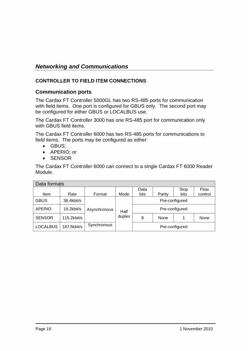
Communication ports The Cardax FT Controller 5000GL has two RS-485 ports for communication with field items. One port is configured for GBUS only. The second port may be configured for either GBUS or LOCALBUS use. The Cardax FT Controller 3000 has one RS-485 port for communication only with GBUS field items. The Cardax FT Controller 6000 has two RS-485 ports for communications to field items. The ports may be configured as either:
• GBUS; • APERIO; or • SENSOR
The Cardax FT Controller 6000 can connect to a single Cardax FT 6000 Reader Module. Data formats
Item Rate Format Mode Data bits Parity
Stop bits
Flow control
GBUS 38.4kbit/s
Asynchronous Half duplex
Pre-configured
APERIO 19.2kbit/s Pre-configured
SENSOR 115.2kbit/s 8 None 1 None
LOCALBUS 187.5kbit/s Synchronous Pre-configured

Page 20 1 November 2010
Controller Port Details Cardax FT Controller 3000
Port GBUS
or APERIO SENSOR LOCALBUS Devices Trophy FT RAT
1 8 16 4 8 - -
Cardax FT Controller 5000GL
Port GBUS
or APERIO SENSOR LOCALBUS Devices Trophy FT RAT 1 8 16 4 8 - -
2
8 16 4 or 8 - - or
- - - - - 16
Cardax FT Controller 6000
Port GBUS
or APERIO
or SENSOR LOCALBUS Devices Trophy FT RAT
1 8 16 4 8 32 -
2 8 16 4 8 32 -

Page 21 1 November 2010
Power supply requirements The DC supply must maintain 13.6 V ± 15% across the supply terminals of each Cardax FT controller and field device. This supply must be provided on–site. Battery back-up is recommended. Each Cardax FT unit draws between 100 mA and 300 mA, however the Cardax High Density I/O board can draw up to approximately 650 mA when all replays are operated. Note: Cardax FT field devices require a well regulated power source with adequate output filtering. Excessive DC supply noise can affect the card-read range of proximity readers. The Cardax Power Supply Unit provides a tested and approved 8 Amp power supply unit for use with Cardax Controllers and Field Devices. This unit comes with monitored mains power fail and low battery indicators, and an isolated 1 Amp secondary output. For Tautwire and Disturbance Sensors, the voltage drop between the Controller and any Sensor must not be greater than 3 volts DC.
Cabling It is recommended that power and communications circuits are each run in a separate, dedicated cable. However, for short runs of 2 - 3 m, these circuits may share a single cable.
Page 22 1 November 2010
HIGH-LEVEL ETHERNET CONNECTIONS Controllers and Cardax FT Command Centre intercommunicate with each other using TCP/IP. Controllers incorporate a built-in Ethernet transceiver. The TCP/IP presents as: 10BaseT on Controller 3000 and Controller 5000GL units; 10/100BaseT on Controller 6000 standard units and; 10/100/1000BaseT on Controller 6000 (HS) units The Ethernet interface physically realised in an RJ-45 socket. Between controllers and Cardax FT Command Centre, any network capable of carrying TCP/IP can be used. Between controllers and Cardax FT Command Centre, the following TCP or User Datagram Protocol (UDP) ports are used.
File transfer TCP port 21 Bootstrap Protocol Server UDP port 67 Bootstrap Protocol Client UDP port 68 World Wide Web TCP port 80 Controller connection TCP port 1072
Controllers acquire IP addresses after they issue a BootP broadcast request. Cardax FT Command Centre incorporates a BootP service. If a controller is isolated from Cardax FT Command Centre by a router, BootP broadcasts are likely to be blocked. In this case, either the Cardax FT BootP server or a third party BootP or DHCP Server needs to be installed in the same network segment as the controller. The physical Ethernet connection can be unshielded twisted-pair CAT5 cable. The maximum cable length of any Ethernet segment is 100m. A segment is defined as the connection between the Ethernet hub/switch and the controller.

Page 23 1 November 2010
SERVER TO SERVER COMMUNICATIONS
Cardax FT supports inter-connection of servers for enterprise-wide solutions. Servers connect to each other via TCP/IP, using OPC (UA) data protocol.
Multi- Server operation should not be considered as a redundant server solution. In the Cardax FT environment, each server stores configuration, alarm and event data for the local system only. Alarms and events are received at remote workstations, not the remote server. The exception to this rule is the cardholder database. This database is replicated to all servers on the system
WORKSTATION TO SERVER COMMUNICATIONS Cardax FT Command Centre server communicates with its workstations using the Distributed Component Object Model (DCOM) over TCP/IP. Because the amount of data transferred between the workstation and server is both substantial and time critical, any TCP/IP infrastructure used by the communications must meet the following minimum standards.
Ping Times < 20 ms Effective data rate > 4 M bit/s
Between the workstation and server, the following TCP or UDP ports are used. DCE endpoint resolution TCP port 135 DCOM Dynamically-allocated TCP ports Intercom TCP port 1072

Page 24 1 November 2010
ENCRYPTION All communication circuits are encrypted using a method appropriate to the communication path. The following diagram details the encryption used:
Cardax FT Controller
3000/5000GL
RSA-2048 / AES-256
Cardax FT Controller
3000/5000GL
RSA-512 / AES-128
RSA-1024 / AES-256
Cardax FT Controller
6000
Cardax FT Controller
6000
RSA-512 / AES-128
RSA-512 / AES-128
RSA-512 / AES-40
RSA-512 / AES-40
RSA-1024 / AES-256
No Encryption
No Encryption
Cardax FT Remote Arming
Terminal
Cardax FTGBUS Universal Reader Interface
Cardax FT Command Centre
Server
Cardax FT Command Centre
Workstation
Cardax FT Command Centre
Server
Linear Congruent Generator (LCG)i.e. not plaintext
Cardax FT Command Centre
Visitor Management Workstation
RSA-2048 / AES-256IPSec
(operating system dependant)

Page 25 1 November 2010
MODEM ACCESS TO CONTROLLERS As an alternative to Ethernet, controllers may be accessed through a modem. Both the Cardax FT Controller 3000 and Cardax FT Controller 5000GL incorporate an RS232 port which can be connected to a Cardax FT Dialler or Cardax FT Dialler 5000GL. The diallers allow a direct dial-up connection through the public switched telephone network (PSTN) or dial-up access to the Internet. Cardax provides two models for dial-up communications:
Traditional Dial-Up In this example, the Cardax FT Dialler in the controller connects to a modem at the server through the PSTN. The Cardax FT server may have a bank of modems. Either the Cardax FT Controller or the server may initiate a call.
Dial-up Via the Internet In this example, the Cardax FT Dialler in the controller is connected to the PSTN. The server has a connection to the PSTN through a modem as well as access to the Internet. The controller accesses the server by first calling an Internet Service Provider using its dialler. It then establishes a Point-to-Point Protocol (PPP) connection with the server over the Internet. The server accesses the controller by dialling it directly through the PSTN. Cardax has some unique properties in being able to perform this type of dial-up communication in a secure manner.
Common Properties of Dial-Up Controllers Controllers can be configured to dial the server based on
• alarm priority;
• event-alarm buffer threshold; and
• a scheduled time of day. Use of the Secure Sockets Layer protocol ensures that both dial-up options are protected from eavesdropping, tampering, or message forgery.

Page 26 1 November 2010
Comparison of the Two Options Issue Traditional Dial-up Dial-up via the Internet
Security Cardax encrypt all server – controller communications using Secure Sockets Layer (SSL) thus the data is secure
Modems connected to the server must be auto-answer. Auto-answer modems are a security threat to any network and generally should have firewall protection from the rest of the network.
Cardax encrypt all server–controller communications using Secure Sockets Layer (SSL) thus the data is secure.
A secure firewall is placed between the open Internet and the company’s internal network and the Cardax FT server. This maintains a high security level.
Install Cost Must provide a bank of modems and probably some form of firewall as mentioned in the section on Security above.
A firewall must be provided and in many companies these exist prior to Cardax installation.
Operational Cost Each call between Cardax FT Controller and the server will normally incur a call charge; often this will be at toll call rates.
There will be an increased maintenance overhead involved in maintaining the bank of modems and the extra changes for line rentals for external telephone circuits for each modem.
Often calls into ISPs can be done on free call numbers thus no call charge. Costs may be done per KB of data transferred (1 k byte of data will be approximately 10 events at the controller).
In General only one ISP account is required and can be used by all controllers.
Where remote site dial-up is the preferred mode of communication, dial-up through an ISP is likely to have the lowest cost of ownership whilst maintaining a high level of security for the system.

Page 27 1 November 2010
Diverse Communications Routes
The Cardax FT Controller 6000 (HS) has two Ethernet ports to provide a primary plus a redundant connection to a second network connection on the same subnet as the primary connection. Should the primary circuit be interrupted then the Cardax FT Controller 6000 (HS) will automatically switch to the second port.
The Cardax FT Controller 6000 standard version has a single Ethernet connection. In situations where diversity may be required for high-level communications routes, Cardax has identified devices made by Moxa Technologies Inc that can be used for this purpose. Moxa make switches that have two ports, different models support either 10BaseT or 100BaseFX using either multimode or single mode optical fibre. Moxa call these switches EtherDevice servers. There are several options for the design of communications route redundancy. The method used will be determined by site-specific needs and how any existing network infrastructure is designed. Two examples follow that explain how redundancy could be provided using Moxa hardware.

Page 28 1 November 2010
COMMUNICATIONS LOOP
In this example the Moxa devices are connected in a loop with one or more Cardax FT Controllers connected at each node. The alarm relay from the EtherDevice server will be wired to an input on one of the Cardax FT Controllers so that network alarms can be monitored from within the Cardax FT system. In the situation where a network segment between the EtherDevice severs fails, normal communication will continue with other devices via the other paths around the loop. It is also possible to design multiple loops that are cross-connected if desired.

Page 29 1 November 2010
DUAL REDUNDANT CONNECTION TO AN EXISTING SWITCHED NETWORK
Ethernet Backbone
Switch Switch
In this scenario there is an existing network that may or may not have communications redundancy. By cabling two circuits from different switches in different parts of the same building or from different buildings two independent network connections can be presented to one EtherDevice server. The Cardax FT Controllers will be connected to the server. Should one of the circuits fail, the EtherDevice server will transparently change over to the other circuit. It will trigger its alarm output relay that will be wired into an input on one of the Cardax FT Controllers.

Page 30 1 November 2010
Monitoring the network Failure of a network segment, or traffic overload, can cause an alarm condition. Moxa provide alarm reporting by:
• Simple Network Management Protocol (SNMP);
• e-mail; and
• equipment alarm relays. The EtherDevice Server has a special version of firmware that enhances management of its alarm relay. Each of the EtherDevice Server’s eight ports can be selected as active or inactive. In the event that one of them changes state, the alarm relay will be activated. The EtherDevice server’s relay can be wired to Cardax FT system inputs. In this way network failures can be integrated with other Cardax FT events.

Page 31 1 November 2010
Biometric Identification
Cardax FT provides the ability to seamlessly enrol and manage fingerprint templates for biometric identification, by way of integration with the SAGEM MorphoAccess fingerprint reader range. The diagram below outlines the connectivity between the various components involved in the enrolment, template management and access decision making process for biometric identification:
Cardax FT Controller SAGEM MA 2xx/3xx/5xx
Cardax FT Command Centre
Ethernet
Biometric Identification - Fingerprint
Access Decision
Wiegand
Template Management
Fingerprint Enrolment
SAGEM MA 1xx
Access Decision
Wiegand
SAGEM MSO 3xx
USB

Page 32 1 November 2010
Contact Us Cardax is committed to providing you with up-to-date information on our product development initiatives. We will provide further updates on our product development programme and pricing as soon as these are ready for publishing. If you have any questions in the meantime please contact your Cardax office:
Gallagher Security Management Systems Private Bag 3026 Hamilton 3204 New Zealand Telephone +64 7 838 9800 Facsimile +64 7 838 9801 E-mail [email protected]
Cardax also has offices and Representatives located in: Asia Australia Canada Central America China Europe Middle East New Zealand South Africa South America United Kingdom United States of America
http://www.cardax.com
Disclaimer
In accordance with the Gallagher policy of continuing development, designs and specifications are subject to change without notice. Gallagher Security Management Systems is a division of Gallagher Group Limited. Cardax is a registered trademark of Gallagher Group Limited. All other product, brand or trade names mentioned within are the property of their respective trademark owners. Copyright © Gallagher Group Limited 2006 - 2009. All rights reserved.