cargo securement guide - transports.gouv.qc.ca · edited by the direction des communications of the...
TRANSCRIPT

CARGOSECUREMENT
GUIDE2017 edition

CARGOSECUREMENT
GUIDE

This publication was prepared by the Direction générale de la sécurité et du camionnage and edited by the Direction des communications of the ministère des Transports, de la Mobilité durable et de l’Électrification des transports
The content of this publication can be found on the ministère des Transports, de la Mobilité durable et de l’Électrification des transports website at the following address: www.transports.gouv.qc.ca.
This publication is also available in French under the title Guide sur les normes d’arrimage des cargaisons.
To obtain copies of the document or more information, you can:
• Dial 511 (in Québec) or 1-888-355-0511 (elsewhere in North America)
• Visit our website at www.transports.gouv.qc.ca
• Email us at [email protected]
• Write to: Direction des communications Ministère des Transports, de la Mobilité durable et de l’Électrification des transports 700, boul. René-Lévesque Est, 27e étage Québec (Québec) G1R 5H1
© Gouvernement du Québec, ministère des Transports, de la Mobilité durable et de l’Électrification des transports, 2018
978-2-550-80460-4 (PDF)
Legal deposit – 2018 Bibliothèque et Archives nationales du Québec
All rights reserved. Translation of any part of this document or reproduction by any means, in whole or in part, is prohibited without written permission from the Ministère.

WARNINGThe purpose of this publication is to provide information on the Cargo Securement Standards Regulation of the ministère des Transports, de la Mobilité durable et de l’Électrification des transports du Québec (Order in council 583-2005). This regulation adopts, by reference, most of the requirements of Standard 10 of the National Safety Code for Motor Carriers.
The information presented in this document is for guidance only. For more complete information, please refer to the regulations available at the following address: www.transports.gouv.qc.ca.
For several years now, the ministère des Transports, de la Mobilité durable et de l’Électrification des transports du Québec has been working at harmonizing Québec standards with those of other North American administrations. However, in spite of these efforts, some differences may remain. Therefore, even if a vehicle complies with Québec regulations, it is important to check the rules applicable in other administrations before driving the vehicle outside Québec.


V
TABLE OF CONTENTS
INTRODUCTION . . . . . . . . . . . . . . . . . . . . . . . . . . . . . . . . . . . . . . . . . . . . . . . . . . . . . . . . . . . . . . . . . . . . . . . . . . . 1
SECTION 1 GENERAL PRINCIPLES AND DEFINITIONS. . . . . . . . . . . . . . . . . . . . . . . . . . . . . . . . . . . . . . . . . . . 3
1.1 SCOPE . . . . . . . . . . . . . . . . . . . . . . . . . . . . . . . . . . . . . . . . . . . . . . . . . . . . . . . . . . . . . . . . . . . . . . . . . . . . . . . . . . . 3
1.2 DEFINITIONS . . . . . . . . . . . . . . . . . . . . . . . . . . . . . . . . . . . . . . . . . . . . . . . . . . . . . . . . . . . . . . . . . . . . . . . . . . . 4
1.3 GENERAL REQUIREMENTS. . . . . . . . . . . . . . . . . . . . . . . . . . . . . . . . . . . . . . . . . . . . . . . . . . . . . . . . . . 13
General performance criteria . . . . . . . . . . . . . . . . . . . . . . . . . . . . . . . . . . . . . . . . . . . . . . . . . . . . . . . 13
Cargo inspection . . . . . . . . . . . . . . . . . . . . . . . . . . . . . . . . . . . . . . . . . . . . . . . . . . . . . . . . . . . . . . . . . . . . . 13
Securing devices . . . . . . . . . . . . . . . . . . . . . . . . . . . . . . . . . . . . . . . . . . . . . . . . . . . . . . . . . . . . . . . . . . . . . 13
Performance criteria . . . . . . . . . . . . . . . . . . . . . . . . . . . . . . . . . . . . . . . . . . . . . . . . . . . . . . . . . . . . . . . . . 14
Appropriate system . . . . . . . . . . . . . . . . . . . . . . . . . . . . . . . . . . . . . . . . . . . . . . . . . . . . . . . . . . . . . . . . . . 14
1.4 EQUIVALENT MEANS OF SECUREMENT . . . . . . . . . . . . . . . . . . . . . . . . . . . . . . . . . . . . . . . . . . 15
SECTION 2 GENERAL REQUIREMENTS FOR NON-SPECIFIC CARGOS . . . . . . . . . . . . . . . . . . . . 16
2.1 REQUIREMENTS RELATED TO CARGO SECUREMENT SYSTEMS. . . . . . . . . . . . . . . . 16
General requirements. . . . . . . . . . . . . . . . . . . . . . . . . . . . . . . . . . . . . . . . . . . . . . . . . . . . . . . . . . . . . . . . 16
Minimum strength of the securement system. . . . . . . . . . . . . . . . . . . . . . . . . . . . . . . . . . . . 16
Blocking system to prevent forward movement. . . . . . . . . . . . . . . . . . . . . . . . . . . . . . . . . . 18
Prevention of rolling . . . . . . . . . . . . . . . . . . . . . . . . . . . . . . . . . . . . . . . . . . . . . . . . . . . . . . . . . . . . . . . . . 18
Material used for cargo securement . . . . . . . . . . . . . . . . . . . . . . . . . . . . . . . . . . . . . . . . . . . . . . . 18
Placement of articles of cargo . . . . . . . . . . . . . . . . . . . . . . . . . . . . . . . . . . . . . . . . . . . . . . . . . . . . . . 19
Tiedowns . . . . . . . . . . . . . . . . . . . . . . . . . . . . . . . . . . . . . . . . . . . . . . . . . . . . . . . . . . . . . . . . . . . . . . . . . . . . . . 19
Minimum number of tiedowns . . . . . . . . . . . . . . . . . . . . . . . . . . . . . . . . . . . . . . . . . . . . . . . . . . . . . 20
2.2 FRONT-END STRUCTURE . . . . . . . . . . . . . . . . . . . . . . . . . . . . . . . . . . . . . . . . . . . . . . . . . . . . . . . . . . 21
Height and width. . . . . . . . . . . . . . . . . . . . . . . . . . . . . . . . . . . . . . . . . . . . . . . . . . . . . . . . . . . . . . . . . . . . . 21
Strength . . . . . . . . . . . . . . . . . . . . . . . . . . . . . . . . . . . . . . . . . . . . . . . . . . . . . . . . . . . . . . . . . . . . . . . . . . . . . . . 22
Structural resistance to penetration . . . . . . . . . . . . . . . . . . . . . . . . . . . . . . . . . . . . . . . . . . . . . . . 22

VI
SECTION 3 SPECIFIC REQUIREMENTS FOR SPECIFIC CARGOS . . . . . . . . . . . . . . . . . . . . . . . . . . . . . 23
3.1 LOGS . . . . . . . . . . . . . . . . . . . . . . . . . . . . . . . . . . . . . . . . . . . . . . . . . . . . . . . . . . . . . . . . . . . . . . . . . . . . . . . . . . 24
3.2 DRESSED LUMBER. . . . . . . . . . . . . . . . . . . . . . . . . . . . . . . . . . . . . . . . . . . . . . . . . . . . . . . . . . . . . . . . . . . . 28
3.3 METAL COILS . . . . . . . . . . . . . . . . . . . . . . . . . . . . . . . . . . . . . . . . . . . . . . . . . . . . . . . . . . . . . . . . . . . . . . . . . 34
3.4 PAPER ROLLS . . . . . . . . . . . . . . . . . . . . . . . . . . . . . . . . . . . . . . . . . . . . . . . . . . . . . . . . . . . . . . . . . . . . . . . . . 39
3.5 CONCRETE PIPES. . . . . . . . . . . . . . . . . . . . . . . . . . . . . . . . . . . . . . . . . . . . . . . . . . . . . . . . . . . . . . . . . . . . . 47
3.6 INTERMODAL CONTAINERS. . . . . . . . . . . . . . . . . . . . . . . . . . . . . . . . . . . . . . . . . . . . . . . . . . . . . . . . 52
3.7 VEHICLES AS CARGO . . . . . . . . . . . . . . . . . . . . . . . . . . . . . . . . . . . . . . . . . . . . . . . . . . . . . . . . . . . . . . . . 54
3.8 ROLL-ON/ROLL-OFF AND HOOK-LIFT CONTAINERS . . . . . . . . . . . . . . . . . . . . . . . . . . . 58
3.9 BOULDERS . . . . . . . . . . . . . . . . . . . . . . . . . . . . . . . . . . . . . . . . . . . . . . . . . . . . . . . . . . . . . . . . . . . . . . . . . . . . 60
3.10 BULK CARGO . . . . . . . . . . . . . . . . . . . . . . . . . . . . . . . . . . . . . . . . . . . . . . . . . . . . . . . . . . . . . . . . . . . . . . . . . 63
3.11 OTHER CARGO. . . . . . . . . . . . . . . . . . . . . . . . . . . . . . . . . . . . . . . . . . . . . . . . . . . . . . . . . . . . . . . . . . . . . . . 64
APPENDIX . . . . . . . . . . . . . . . . . . . . . . . . . . . . . . . . . . . . . . . . . . . . . . . . . . . . . . . . . . . . . . . . . . . . . . . . . . . . . . . . . 65

1
INTRODUCTION
The Highway Safety Code sets out cargo securement provisions applicable to all road vehicles (heavy or light). The purpose of these legislative and regulatory framework policies is to ensure that cargos or objects transported by road vehicles are firmly and adequately secured so as to ensure the stability of the vehicle and make sure the objects that are transported do not fall or hit other vehicles or road users.
Heavy vehicles transport cargos of many different types and shapes, which are, most of the time, massive and bulky. They pose higher risks and require special securement provisions. Provisions applicable to heavy vehicles have therefore been specified in the Cargo Securement Standards Regulation (chapter C-24.2, r.30), hereinafter referred to as “CSSR”.
The CSSR first defines the general performance criteria that must be complied with to make sure that the cargo remains in place during transportation. It sets the minimum strength required for securement systems. This regulation is different from other regulations applicable to heavy vehicles, as it imposes an obligation of result and provides, in certain cases, some flexibility as regards the means to be taken to achieve the required performance.
Furthermore, in common situations, it may be difficult, or even impossible, to measure the efficiency of a securement system based on the general performance criteria. To facilitate compliance with these criteria, the CSSR prescribes the most common and efficient cargo securement means and devices. These means and devices can be used for most cargos composed of general commodities. For specific cargos, the CSSR prescribes specific securement systems and devices.
Whether they are intended for general commodities or specific cargos, the securement systems and means prescribed by the CSSR are deemed to be compliant with the general performance criteria.
The provisions of the CSSR integrate the provisions of Standard 10 of the National Safety Code (NSC), published by the Canadian Council of Motor Transport Adminis-trators (CCMTA), and available at www.ccmta.ca.
The guide provides information on the regulation governing the securement of cargos transported by heavy vehicles. It contains examples and practical explanations intended for owners, operators and drivers of heavy vehicles, as well as for shippers and other stakeholders concerned by cargo securement, so as to help them comply with the regulation.

2
This document is divided in three sections:
Section 1 - General Principles and Definitions
This section specifies the scope and provides definitions for a better understanding of the CSSR and of Standard 10 of the NSC. It deals with the general performance criteria and explains the concept of recognized equivalent means of securement.
Section 2 - General Requirements for Non-Specific Cargos
This section explains the requirements regarding the systems and tiedowns recognized by the CSSR for the securement of general cargos not included in Section 3, and provides examples.
Section 3 - Specific Requirements for Specific Cargos
This section presents the specific requirements applicable to nine (9) specific types of cargos.

3
SECTION 1
GENERAL PRINCIPLES AND DEFINITIONS
1.1 SCOPE
The Cargo Securement Standards Regulation applies to:
Road vehicles or combinations of road vehicles having a gross vehicle weight rating (GVWR) of 4 500 kg or more, or a gross combination weight rating of 4 500 kg or more.
GVWR = Gross vehicle weight rating displayed on the vehicle identifi cation plate. In the case of a combina-tion of road vehicles, the sum of all the vehicles’ GVWR must be taken into consideration.
Buses, minibuses or tow trucks, regardless of the weight.
Section 519.8 of the Highway Safety Code sets out specifi c provisions regarding freight securement in buses.
Section 471 of the Highway Safety Code sets out general and specifi c provisions concerning the securement of cargo in or on all road vehicles.
The Cargo Securement Standards Regulation does not apply to:
Farm motor vehicles or farm trailers within the meaning of the Regulation respecting road vehicle registration, when the following three conditions are met:
• A warning sign is fixed to the rear of the vehicle or combination of vehicles (section 274 of the Highway Safety Code);
• The vehicle travels at a speed of less than 40 km/h;
• The cargo is contained against the struc-ture of the vehicle and the structure is strong enough to prevent any horizontal movement, or the cargo is secured to prevent such movement.
GVWR 15 000 kg
Total GVWR 6 500 kg
GVWR 2 000 kg GVWR 4 500 kg

4
1.2 DEFINITIONS (Standard 10, Part 1)
Anchor point
The part of the structure, fitting or attach-ment on a vehicle or cargo to which a tiedown is attached.
Blocking
A substantial structure, device or article of appropriate size placed against or around cargo to prevent horizontal movement.
Bolster
A transverse, load bearing, structural hori-zontal component of a bunk securing device.
Boulder
A single piece of natural or quarried, irregu-larly shaped rock, that weighs 5 000 kg or more, or has a volume of more than 2 m3.
Bracing
A structure, device or article placed against another structure, device or article to prevent tipping.
Bulk
This term includes different categories of products that are transported without being packed (aggregates, liquids, gas, granular products, etc.).

5
Bulkhead
A vertical barrier (net, rigid or fl exible partition) set across a vehicle to prevent the cargo from moving forward.
Not to be confused with a front-end structure.
Bundle
Articles that have been unitized for the purpose of securing them as a single article with a uniform shape.
Bunk
A horizontal bolster that is installed trans-versely across a vehicle, and is fi tted with a stake at each end.
Cab shield
A vertical barrier placed directly behind the cab of a truck or truck tractor and capable of protecting the driver if the cargo moves forward.
Cargo
All articles or material carried by a vehicle, including those used in the operation of the vehicle.
Cargo securement system
The method by which cargo is contained or secured; it includes vehicle structures, securing devices and all components of the system.

6
Chock
A tapered or wedge-shaped part used to prevent round articles from rolling.
Cleat
A short piece of material nailed to the deck to reinforce blocking.
Coil bunk
A device that keeps the timbers supporting a metal coil in place.
Concrete pipe
Small pipe: pipe with an inside diameter of up to 114.3 cm.
Large pipe: pipe with an inside diameter of more than 114.3 cm.
Bell pipe: pipe with a flanged end that is bigger in diameter than the barrel.
Contained
Cargo in a sided vehicle, where every article is in contact with a wall or other articles and cannot move horizontally or tip.
Container chassis vehicle
A vehicle specifically built for and fitted with locking devices for the transport of intermodal containers.
7
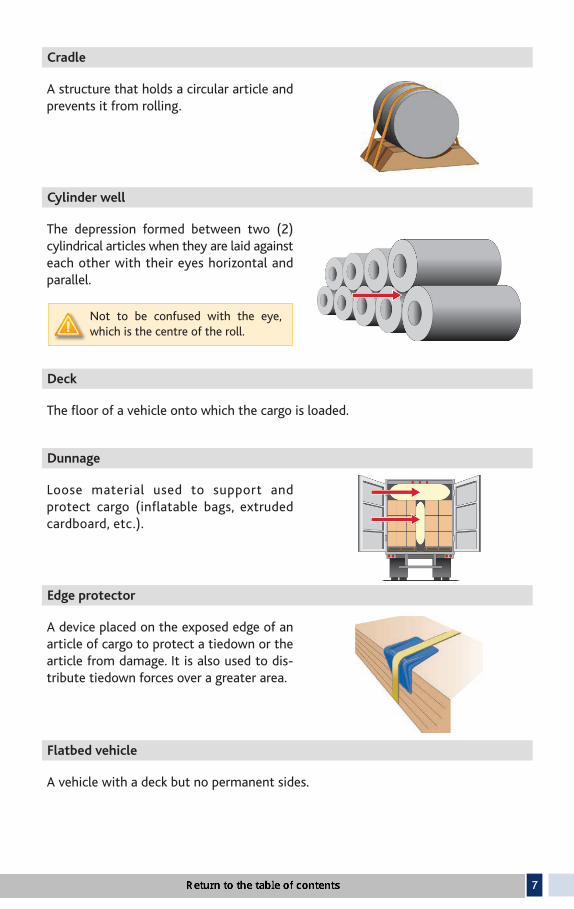
Cradle
A structure that holds a circular article and prevents it from rolling.
Cylinder well
The depression formed between two (2) cylindrical articles when they are laid against each other with their eyes horizontal and parallel.
Not to be confused with the eye, which is the centre of the roll.
Deck
The fl oor of a vehicle onto which the cargo is loaded.
Dunnage
Loose material used to support and protect cargo (inflatable bags, extruded cardboard, etc.).
Edge protector
A device placed on the exposed edge of an article of cargo to protect a tiedown or the article from damage. It is also used to dis-tribute tiedown forces over a greater area.
Flatbed vehicle
A vehicle with a deck but no permanent sides.

8
Frame vehicle
A vehicle that has a skeletal structure fi tted with a front bunk and a rear bunk that together cradle a stack of logs as an integral part of the vehicle.
Friction mat
A device placed between a deck and cargo, or between articles of cargo, that increases the friction between them.
Front-end structure
A vertical barrier across the front of a deck that prevents cargo from moving forward.
Not to be confused with a bulkhead or cab shield.
Heavy vehicle
For the purpose of applying section 89 of standard 10: A vehicle that weighs more than 4,500 kg, or any piece of equipment or machinery on wheels or tracks that weighs more than 4,500 kg.
Hook lift container
A specialized container that is loaded and unloaded onto a tilt frame body by an articulating hook-arm.
Integral locking device
A device that is designed and used to restrain an article of cargo by connecting and locking attachment points on the article to anchor points on the vehicle.
Integral securement system
A roll-on/roll-off container or a hook-lift container and the vehicle used to transport them, which are equipped with compatible front and rear hold-down devices that secure the container to the vehicle.

9
Intermodal container
A reusable, transportable container that is specially designed with integral locking devices so it can be secured to a container chassis vehicle.
Lengthwise
Means along the vehicle.
Light vehicle
For the applicability of Standard 10, section 88: An automobile, truck or van that weighs 4 500 kg or less.
Log
Trunks or sections of trunks from felled, lopped and topped trees (with or without bark), wooden poles (utility, telephone, lights) and wooden posts log.
• Shortwood: logs not longer than 4.9 m.
• Longwood: logs longer than 4.9 m.
Metal coils
A coiled sheet metal shaped as a roll. The empty part at the centre of the roll is called the “eye”.
Coils of steel wires, steel wire ropes or any other types of steel wrapped around a coil used as a support are not considered metal coils for the purposes of this regulation.
Pallet
A platform or tray on which cargo is placed so that it can be handled as a unit.
Eye

10
Pole trailer
A trailer with a frame that consists only of a drawbar.
Not to be confused with a semi-trailer fi tted to carry logs.
Rail vehicle
A vehicle fi tted with stakes at the front and rear to contain logs loaded crosswise.
Restrain
Prevent cargo articles from tipping or moving.
Roll-on/roll-off container
A specialized container which is loaded and unloaded onto a tilt frame body by a lifting mechanism in conjunction with rollers which are fi xed to the container.
Rub rail
A rail along the side of a vehicle that protects the side of the vehicle from impact.
Securing device
A device specifi cally designed and manufactured to attach, restrain or secure cargo such as a chain, strap or tensioning device, etc.

11
Shoring bar
A device placed transversely between the walls of a vehicle and the cargo to prevent the cargo from tipping or moving.
Sided vehicle
A vehicle, including a van, a dump bodied vehicle and a sided intermodal container carried by another vehicle, with a cargo compartment that is enclosed on all sides by walls that:
• are strong enough to contain the cargo, and;
• may have latched openings for loading and unloading.
Spacer
Material placed under an article, or between layers of articles, to make loading and unloading easier.
Stake
A part, including a standard, that is mounted close to vertical on a vehicle frame or as part of a bunk, and that immobilizes cargo placed against it.
Strapping
Tensioned strips of material such as steel or nylon that are clamped or crimped back on themselves.
Tiedown
A combination of securing devices that are attached to one or more anchor points on a vehicle.

12
Unitized
Cargo articles that are wrapped, banded or bound together so they can be handled as a single article.
A unitized article is also called a “bundle”.
Vehicle
A truck or a truck tractor used individually or in combination with one or more semi-trailers or trailers.
Void fi ller
Material that is used to fi ll a space between the cargo and the structure of the vehicle, and is strong enough to prevent the cargo from moving.
Working Load Limit (WLL)
The maximum load indicated by the manufacturer that may be applied to a component of a cargo securement system or a tiedown during normal service.
Under the CSSR, all tiedowns used to secure a cargo must bear the manufacturer’s certifi cate specifying the working load limit.

13
1.3 GENERAL REQUIREMENTS
General performance criteria (Standard 10, sections 3 to 7)
When a vehicle increases its speed (acceleration), because of the inertia forces, the cargo resists movement and tends to move in a rearward direction. Conversely, when a vehicle reduces its speed (deceleration or braking), the cargo maintains its speed because of the inertia forces and tends to move forward. During changes in direction (turning, changing lanes, avoiding obstacles, etc.), because of the centrifugal force, the cargo tends to move to the outside of the turn. In addition, the cargo may also move toward the front and sides of a vehicle travelling on a road with a slope or inclined to the left or to the right.
The purpose of the Cargo Securement Standards Regulation is to establish the minimum requirements and methods to be applied, and to determine the securement components to be used so as to prevent the cargo from moving or shifting. The appropriate use of cargo securement systems contributes to ensuring the stability of the vehicle on the road.
The Regulation provides general performance criteria related to inspection, securing devices and cargo securement systems.
Cargo inspection (Standard 10, section 3)
The driver of a vehicle transporting a cargo must inspect the cargo and the cargo securement system, and make necessary adjustments:
• before driving the vehicle;• not more than 80 km from the point where the cargo was loaded;• after 240 km or 3 hours of driving;• after each change of activity;• before leaving a private road to enter a public highway.
These inspection requirements do not apply if:• the cargo is sealed in a vehicle and the driver has been ordered not to open it to
inspect the cargo
OR• the vehicle is loaded in a manner that makes the cargo, or portions of the cargo,
inaccessible.
Securing devices (Standard 10, sections 4, 15 and 19)
All components of a cargo securement system:• must be in proper working order;• must be fit for the purpose for which they are used;• must not have knots, or any damaged or weakened elements that could adversely
affect their performance;• must not have any cracks or cuts.

14
The securing devices, integral locking devices, movable structures or blocking devices must be secured in a manner that prevent them from becoming unfastened while the vehicle is on a public highway.
Wherever possible, and where a vehicle is equipped with rub rails, securing devices should be located inboard the rub rails.
Performance criteria (Standard 10, section 5)
The cargo securement system must be capable of withstanding the forces resulting from, for example:
• manœuvres of the driver in normal and emergency conditions;
• acceleration and braking of the vehicle, including emergency braking;
• the road geometry (curve radius, cross slope);
• the condition of the roadway;
• the wind.
The cargo securement system must prevent the cargo from moving when subjected to a force corresponding to:
• 50% of its weight toward the sides;
• 80% of its weight toward the front;
• 20% of its weight upward, if the cargo is not entirely contained.
The load on each component of a cargo securement system that reacts to a force mentioned above must not exceed the working load limit (WLL) of the component.
Appropriate system (Standard 10, section 6)
The cargo securement system used to contain, immobilize or restrain cargo, must be:
• appropriate for the size, shape, strength and characteristics of the cargo;
• designed and constructed for the purpose for which it is used;
• used and maintained in accordance with the manufacturer’s instructions.
15
1.4 EQUIVALENT MEANS OF SECUREMENT (CSSR, section 3 and Standard 10, section 7)
Cargo securement must meet the previously mentioned performance criteria which are described in section 5 of Standard 10. Where applicable, cargo must be contained, immobilized or secured on or inside a vehicle, in compliance with Divisions 3, 4 and 5 of Part 1 of Standard 10, and with Part 2 of Standard 10.
Under the Regulation, operators may use a securement method or system that is not mentioned in the Regulation, provided they can establish that the method or system used meets the performance criteria described in section 3 of the Regulation.
In this case, the operator must provide the MTMDET with calculations and a complete securement plan certified by a professional engineer who is a member of the Ordre des ingénieurs du Québec.

16
SECTION 2
GENERAL REQUIREMENTSFOR NON-SPECIFIC CARGOS
This section applies to all types of cargo, with the exception of commodities carried in bulk in sided vehicles, such as dump bodies and tanks specifi cally manufactured to transport the commodities (Standard 10, section 8).
The general rules set out in Section 2 of this guide concern restraining means, tiedowns and their load limits, as well as blocking methods. They apply to most types of cargo.
Note that semi-trailers with fl exible sides, also referred to as “curtain sided semi-trailers”, cannot be considered as sided vehicles. The general provisions apply as if these were fl atbed semi-trailers.
2.1 REQUIREMENTS RELATED TO CARGO SECUREMENT SYSTEMS (CSSR, sections 4 and 5, and Standard 10, sections 9 to 18)
General requirements (Standard 10, section 9)
Cargo must be fi rmly immobilized or secured to prevent it from moving, slipping or tilting using:
• structures of adequate strength (side walls, fl oor and anchor points);
• blocking, dunnage or dunnage bags;
• bracing or shoring bars;
• tiedowns;
• friction mats; or
• a combination of these methods.
Minimum strength of the securement system (Standard 10, sections 10 and 11)
The sum of the working load limits (WLL) of all tiedowns used to secure an article or group of articles on a vehicle represents the aggregate WLL.
The aggregate WLL of all tiedowns must be at least 50% of the loaded cargo.

17
The aggregate WLL is calculated by adding:
• 50% of the WLL of each tiedown for each section of a tiedown that is attached to an anchor point of the vehicle; and
• 50% of the WLL of each tiedown for each section of the tiedown that is attached to the article or group of articles.
When a WLL is identified by a label refer-ring to the numerical value of the WLL (e.g. 3 000 kg), this label is deemed to be the WLL of the device or component.
In the absence of a numeric WLL, a tie-down or component of a tiedown must be marked by its manufacturer with respect to its WLL. The mark can refer to:
• the WLL value
OR• an acronym referring to a standard
(mentioned in Part 4 of Standard 10) and indicating an equivalent WLL.
– For example, a chain that is compliant with the standard of the National Association of Chain Manufacturers has a WLL equivalent to that standard, according to the grade and size indica ted on the chain.
EXAMPLES OF WLL FOR CHAINS
Grade 70 (transport)
Grade 100 (steel alloy)
Mark on chain
7 70
700
10 100
1000
Size mm
Working load limit (WLL) kg
10 mm 2 990 kg 4 000 kg
11 mm 3 970 kg —
13 mm 5 130 kg 6 800 kg

18
Blocking system to prevent forward movement(Standard 10, section 14)
The aggregate WLL of the components of a blocking system used as a unique form of securement to prevent an article of cargo from moving forward, including tiedowns used as blocking, must not be less than 50% of the article being blocked.
Prevention of rolling (Standard 10, section 18)
Where any article of cargo may roll during transport, it must be restrained by chocks, wedges, cradles or any other securing devices.
Material used for cargo securement (Standard 10, section 16)
Material used as dunnage, chocks or cradles or for blocking or bracing must be strong enough that it will not be split or crushed by the cargo or tiedowns.
When wood is used, it is recommended to use hard, properly dried wood, without rot or any knots, holes or cracks.
Timbers used for blocking or bracing must have a wood texture that extends lengthwise.

19
Placement of articles of cargo (Standard 10, section 17)
Where the articles of cargo (on or within a vehicle) are placed beside each other and secured by tiedowns passing over two (2) or more articles, the articles must be:
• placed in direct contact with each other
OR• prevented from moving toward each
other using a blocking system or void fi llers.
Tiedowns
Tension (Standard 10, section 19)
A tiedown must be:
• designed, constructed and maintained so that the driver of the vehicle can tighten it;
• used in a manner that prevents the tiedown from slipping, loosening, unfastening, opening or releasing while the vehicle is on a public highway.
Drivers are responsible for making sure that tiedowns are taut while the vehicle is on a public highway.
Edge protectors (Standard 10, section 20)
An edge protector must:
• be used where a tiedown would be subject to abrasion or cutting at the point where it touches an article of cargo;
• be resistant to abrasion, cuts and crushing;
• allow the tiedown to slide freely when it is tightened or loosened.
20
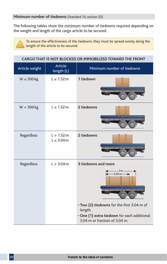
Minimum number of tiedowns (Standard 10, section 22)
The following tables show the minimum number of tiedowns required depending on the weight and length of the cargo article to be secured.
To ensure the effectiveness of the tiedowns, they must be spread evenly along the length of the article to be secured.
CARGO THAT IS NOT BLOCKED OR IMMOBILIZED TOWARD THE FRONT
Article weightArticle
length (L)Minimum number of tiedowns
W ≤ 500 kg L ≤ 1.52 m 1 tiedown
W > 500 kg L ≤ 1.52 m 2 tiedowns
Regardless L > 1.52 m L ≤ 3.04 m
2 tiedowns
Regardless L > 3.04 m 3 tiedowns and more
• Two (2) tiedowns for the fi rst 3.04 m of length.
• One (1) extra tiedown for each additional 3.04 m or fraction of 3.04 m.

21
CARGO BLOCKED OR IMMOBILIZED TOWARD THE FRONT
A cargo is considered blocked or immobilized if a front-end structure bulkhead, other immobilized cargo or another device prevents it from moving forward.
Article weightArticle
length (L) Minimum number of tiedowns
Regardless L ≤ 3.04 m 1 tiedown
Regardless L > 3.04 m 2 tiedowns and more
• One (1) tiedown for the fi rst 3.04 m of length.
• One (1) extra tiedown for each additional 3.04 m or fraction of 3.04 m.
2.2 FRONT-END STRUCTURE
Height and width (Standard 10, section 24)
The height of the front-end structure of the vehicle must not be shorter than the shorter of the following two measures:
• the height at which it prevents the cargo from moving forward
OR• 122 cm above the deck.
The width of the front-end structure of a vehicle must not be narrower than the narrower of the following two measures:
• the width of the vehicle
OR• the width at which it prevents the cargo from moving forward.

22
Strength (Standard 10, sections 25)
When it is in contact with the merchandise, the front-end structure of a vehicle must have a strength (P) of at least the percentage of the total weight of the cargo corresponding to the values indicated in the figure below.
Structural resistance to penetration (Standard 10, section 26)
When a front-end structure or blocking device comes in contact with an article of cargo, it must also:
• withstand the forward pressure of the cargo articles when the vehicle decele-rates at 0.6 g;
• be exempt of an opening or gap that is big enough to permit an article of cargo to pass through it.
It is essential for owners or operators of vehicles or trailers to know the strength of the structure. Manufacturers and salespersons usually have that information.

23
SECTION 3
SPECIFIC REQUIREMENTS FOR SPECIFIC CARGOS (CSSR 10, SECTIONS 6 TO 16) (Standard 10, section 27)
This section applies to specific types of cargo that require specific securement methods. The requirements presented in this section therefore supplement the requirements described in Section 2 (general securement requirements) and do not replace them.
However, if situations presented in this section require containing, immobilizing or securing methods which differ from those described in Section 2, the provisions of Section 3 must apply in priority.
This section applies to the transportation of:
3.1 Logs (CSSR, section 7)
3.2 Dressed lumber (CSSR, section 8)
3.3 Metal coils (CSSR, section 9)
3.4 Paper rolls (CSSR, section 10)
3.5 Concrete pipes (CSSR, section 11)
3.6 Intermodal containers (CSSR, section 12)
3.7 Cargo of vehicles (CSSR, section 14)
3.8 Roll-on/roll-off and hook-lift containers (CSSR, section 13)
3.9 Boulders (CSSR, section 15)
3.10 Bulk cargo (CSSR, section 16)
3.11 Other cargo

24
3.1 LOGS
LOG CONFIGURATION (Short or longwood)
TIEDOWNS
The outer logs in the bottom layer of logs must be in contact with a bunk, bolster or stake. (Standard 10, section 30(2))
Tiedowns must be used to secure the load, in combination with bunks, bolsters, stakes, or other means of cradling the logs. (Standard 10, section 31)
Sufficient additional tiedowns or securing devices must be used to ensure that no part of the cargo becomes dislodged where:
• logs could slip against each other because of a low friction
OR
• a log is not held in place by contact with other logs or by the bunks, bolsters or stakes.
(Standard 10, section 33)
Outside logs on a stack of logs must be held down or touch at least two (2) bunks, bolsters or stakes;
ORWhere one end of a log does not touch a bunk, bolster or stake, it must rest on other logs in a stable manner, and extend beyond the end of the bunk, bolster or stake to prevent it from moving out. (Standard 10, section 30(3))
The centre of the highest outside log on each side or end of the vehicle must be lower than the tops of the bunks or stakes. (Standard 10, section 30(4))
The upper logs that form the top of the cargo must be crowned (semi-circle). (Standard 10, section 30(5))

25
SPECIFIC PROVISIONS FOR SHORTWOOD(not longer than 4.9 m)
CONFIGURATION ANDNUMBER OF STACKS
REQUIREMENTS
CrosswiseOne or more stacks (Standard 10, section 34)
The end of a log in the lower layer of shortwood must not extend more than 1/3 of the log’s total length beyond the nearest supporting structure on the vehicle.
CrosswiseOne stack (Standard 10, section 35)
The stack must be secured by at least two (2) tiedowns that must:
• be attached to the vehicle frame at the front and rear, at about 1/3 of the length of the logs.
Vehicles built after December 31, 2009 must be equipped with a device that maintains a tension of at least 900 kg and takes up slack in the tiedown.
CrosswiseTwo (2) stacks (Standard 10, section 36)
Two stacks loaded side by side must be loaded so that:
• there is no space between the two stacks;
• the outside of each stack is raised by a piece of metal at least 25 mm high within 10 cm of the end of the logs or the side of the vehicle;
• the highest log is not more than 2.44 m above the deck;
• at least one (1) tiedown is used lengthwise across each stack:
– about midway between the stakes,
– attached to the vehicle frame at the front and rear of the load.
Vehicles built after December 31, 2009 must be equipped with a device that maintains a tension of at least 900 kg and takes up slack in the tiedown.

26
SPECIFIC PROVISIONS FOR SHORTWOOD(not longer than 4.9 m)
CONFIGURATION AND NUMBER OF STACKS
REQUIREMENTS
CrosswiseOne or more stacks and cargo carrying surface longer than 10 m (Standard 10, section 37)
The vehicle must have centre stakes that divide the load into equal sections.
Each tiedown must secure the highest log on each side of the centre stake and be fastened below that highest log.
Also, each tiedown must:
• be fi xed at each end and tensioned from the middle
OR• be fi xed in the middle and tensioned
from each end
OR• pass through a pulley or similar device
in the middle of the tiedown and be tensioned from one end.
Lengthwise(Standard 10, section 38)
Each stack of shortwood must be secured by at least two (2) tiedowns.
The aggregate WLL of tiedowns used to secure each stack must be at least 1/6 of the weight of the stack.
LengthwiseStack blocked at the front and rear and logs shorter than 3.04 m(Standard 10, section 38)
Where a stack (with logs shorter than 3.04 m) is blocked at the front and rear by the vehicle’s end structure or a wall that is strong enough to restrain the cargo or by another stack:
• the stack must be secured by a single tiedown located midway between the bunks or stakes.
The aggregate WLL of the tiedowns used to secure each stack must be at least 1/6 of the weight of the stack.

27
SPECIFIC PROVISIONS FOR LONGWOOD(longer than 4.9 m)
LOG CONFIGURATIONAND TYPES OF VEHICLES
REQUIREMENTS
Lengthwise(Standard 10, section 39)
Longwood must be secured to the vehicle by at least two (2) tiedowns.
The aggregate WLL of the tiedowns used to secure each stack must be at least 1/6 of the weight of the stack.
LengthwisePole trailersRegardless of the length of the logs(Standard 10, section 40)
Logs must be secured by:
• at least one (1) tiedown at each bunk
OR• at least two (2) tiedowns used as
wrappers that encircle the entire stack of logs at suffi cient locations along the stack to secure it effectively. The wrappers must be set:– at the front and rear ends
AND– at least 3.04 m apart.
Where the vehicle is transporting one (1) or two (2) logs with diameters greater than 0.6 m:
• each log must be individually immobilized with chock blocks or an equally effective method.
Where a log with a diameter greater than 0.6 m rises above the bunks:
• it must be secured to the underlying logs with at least two (2) other tiedowns used as wrappers.

28
3.2 DRESSED LUMBER (Standard 10, Part 2, Division 2)
This section applies to the following products transported on fl atbed vehicles:
• bundles of dressed lumber and packaged lumber, and;
• unitized building products, including plywood, gypsum board or other materials of similar shape.
Dressed lumber and similar bundled building products being transported in enclosed trucks or trailers can be secured in accordance with the requirements presented in this section or with the general requirements set out in Section 2 of this guide (Standard 10, Part 1).
This section does not apply to building products loaded on pallets or packages of engineered wood products such as beams or trusses.
BUNDLECONFIGURATION
SECUREMENT REQUIREMENTS
EXAMPLES3.66 m long bundles
Side by side(Standard 10,section 42)
Where bundles are placed side by side:
• they must be in direct contact with each other
OR• a method must be used
that prevents the bundles from moving toward each other.
Single layer(Standard 10,sections 19 and 21 to 23)
Bundles must be secured:
• in accordance with the requirements set out in Section 2 of this guide
AND• according to the way
bundles are blocked.
Blocked by a front-end device
Not blocked by a front-end device

29
BUNDLECONFIGURATION
SECUREMENT REQUIREMENTS
EXAMPLES3.66 m long bundles
Two (2) or more layers and bundles blocked against lateral movements by stakes(Standard 10,section 44)
Bundles must be secured:
• by tiedowns laid out over the top layer, as outlined in the general requirements of Section 2 of this guide(Standard 10, section 22).
Two (2) or more layersandbundles restrained from lateral movement by blocking or high friction devices(Standard 10,section 45)
Bundles must be secured:
• by tiedowns laid out over the top layer, as outlined in the general requirements of Section 2 of this guide (Standard 10, section 22).
Examples of blocking or high friction devices:
• Friction or nail mat.
• Timbers with friction surface.
• Other specialized equipment.
Not blocked by a front-end device
Not blocked by a front-end device
Blocked by a front-end device
Blocked by a front-end device

30
BUNDLECONFIGURATION
SECUREMENT REQUIREMENTS
EXAMPLES3.66 m long bundles
Two (2) or more layersandbundles placed directly on top of other bundles or on spacers of adequate size and orientation (Standard 10,section 46)
Bundles must be secured:
• by tiedowns laid out over the top layer, as outlined in the general requirements of Section 2 of this guide. (Standard 10, section 22)
WITH• at least two (2)
tiedowns laid out over each bundle longer than 1.52 m.
Requirements for spacers:
• The length of spacers must provide support to all pieces in the bottom row of the bundle.
• The width of the spacers must be equal to or greater than their height.
• Spacers must provide good interlayer friction.
Not blocked by a front-end device
Blocked by a front-end device

31
BUNDLECONFIGURATION
SECUREMENT REQUIREMENTS
EXAMPLES3.66 m long bundles
Three (3) or more layersandbundles placed directly on top of other bundles or on spacers of adequate size and orientation(Standard 10,section 46)
Bundles must be secured:
• by tiedowns laid out over the top layer of bundles, as outlined in the general requirements of Section 2 of this guide (Standard 10, section 22)
AND• tiedowns laid out over
the middle layer of bundles in accordance with the provisions of Section 2 of this guide (Standard 10, section 22), for each stack of bundles higher than 1.85 m.
Requirements for spacers:
• The length of spacers must provide support to all pieces in the bottom row of the bundle.
• The width of the spacers must be equal to or greater than their height.
• Spacers must provide good interlayer friction.
Two (2) or more layers, in all other circumstances (Standard 10, section 47)
Bundles must be secured:
• by tiedowns laid out over each layer of bundles, in accordance with the provisions of Section 2 of this guide (Standard 10, section 22)
AND• by at least two (2) tiedowns over each top bundle(s) longer
than 1.52 m.
Not blocked by a front-end device
Blocked by a front-end device

32
NUMBER OF TIEDOWNS REQUIRED BASED ON THE LENGTH (L) OF THE BUNDLES AND THE TOTAL HEIGHT (H) OF THE STACK
CASE 1: BUNDLES BLOCKED (By a front-end structure or another stack)
Description of bundles
Number of layers and total height (H)
of the stack
Number of tiedowns per
bundle for the top layer
Number of tiedowns per
bundle for the middle layers
L ≤ 1.52 m
2 layers, regardless of the height
OR
3 layers or more and H ≤1.85 m
1 Not required
3 layers or more and H >1.85 m
1 1
L > 1.52 m AND
L ≤ 3.04 m
2 layers, regardless of the height
OR
3 layers or more and H ≤1.85 m
2 Not required
3 layers or more and H >1.85 m
2 1
L > 3.04 m
2 layers, regardless of the height
OR
3 layers or more and H ≤1.85 m
1 for the first 3.04 m of length AND 1 for each fraction of 3.04 m
Not required
3 layers or more and H >1.85 m
1 for the first 3.04 m of length
AND1 for each fraction of 3.04 m
1 for the first 3.04 m of length
AND
1 for each fraction of 3.04 m

33
CASE 2 BUNDLES NOT BLOCKED
Description of bundles
Number of layers and total height (H)
of the stack
Number of tiedowns per
bundle for the top layer
Number of tiedowns per
bundle for the middle layers
≤ 1.52 m AND≤ 500 kg
2 layers,regardless of the heightOR3 layers or more andH ≤1.85 m
1 Not required
3 layers or more and H >1.85 m
1 1
> 1.52 m AND> 500 kg
2 layers,regardless of the heightOR3 layers or more andH ≤1.85 m
2 Not required
3 layers or more and H >1.85 m
2 2
L > 1.52 m ANDL ≤ 3.04 m
2 layers,regardless of the heightOR3 layers or more andH ≤1.85 m
2 Not required
3 layers or more and H >1.85 m
2 2
L > 3.04 m
2 layers,regardless of the heightOR3 layers or more andH ≤1.85 m
2 for the fi rst 3.04 m of lengthAND1 for each fraction of 3.04 m
Not required
3 layers or more and H >1.85 m
2 for the fi rst 3.04 m of lengthAND1 for each fraction of 3.04 m
2 for the fi rst 3.04 m of lengthAND1 for each fraction of 3.04 m
Additional tiedowns may be required to ensure that the aggregate working load limit is at least 50% of the total weight of the secured cargo (Standard 10, section 10).

34
3.3 METAL COILS (Standard 10, Part 2, Division 3)
This section applies to the transportation of one or more metal coils whose total weight, individually or together, is 2 268 kg or more, and that are carried:
• on fl atbed vehicles;
• in sided vehicles;
• in intermodal containers.
Metal coils weighting less than 2 268 kg may be secured in accordance with the provisions of this section or with the requirements set out in Section 2, “General Requirements”, of this guide.
COILS TRANSPORTED BY A FLATBED VEHICLE OR INTERMODAL CONTAINER
COILS WITH EYES VERTICAL
NUMBER OF COILS/ CONFIGURATION
TIEDOWNS REQUIREDIMMOBILIZING
COILS
A single coil or several coils not grouped in a row (Standard 10, section 49)
Each coil must be secured by at least three (3) tiedowns attached across the eye of the coil, including:
• one (1) attached diagonally from the left side to the right side of the vehicle;
• one (1) attached diagonally from the right side to the left side of the vehicle;
• at least one (1) attached transversely.
Blocking, bracing, or friction mats must be used to prevent coils from moving forward.
Tiedowns must be arranged in a manner that prevents coils from tipping forward, rearward, or sideways.

35
COILS WITH EYES VERTICAL
NUMBER OF COILS/ CONFIGURATION
TIEDOWNS REQUIREDIMMOBILIZING
COILS
Coils grouped and loaded side by side in a transverse or lengthwise row (Standard 10, section 49)
Each row of coils must be secured by:
• at least two (2) tiedowns attached across the front and rear of the row of coils;
• at least one (1) tiedown attached over the top of each coil or row of coils.
Tiedowns attached across must, where practical, make an angle of not more than 45o with the deck of the vehicle, when viewed from the side.
Blocking, bracing, or friction mats must be used to prevent coils from moving forward.
Tiedowns must be arranged in a manner that prevents coils from tipping forward, rearward, or sideways.

36
COILS WITH EYES CROSSWISE
NUMBER OF COILS/ CONFIGURATION TIEDOWNS REQUIRED
IMMOBILIZING COILS
A single coil or several coils (Standard 10, section 50)
Each coil must be secured by:
• at least two (2) tiedowns through the eye of the coil to prevent forward and rearward movements.
Where practical, tiedowns must make an angle of 45o with the deck, when viewed from the side.
If coils are in contact with each other in the longitudinal direction, and tiedowns prevent them from moving:
• Only the foremost and rearmost coils or rows of coils must be secured in accordance with section 50(2) of Standard 10, as explained in the upper part of the section to the right.
• A single tiedown restraining against forward motion may be used to secure all the coils except the rearmost one, which must be restrained against rearward motion.
Each coil must be immobilized with timbers, chocks wedges, a cradle or other device that (Standard 10, section 50(2)):
• prevents the coil from rolling;
• supports the coil off the deck;
• cannot become unfastened or loose during transport.
The devices used must be held in place by coil bunks or similar devices to prevent the blocking devices from coming loose.
The use of nailed wood blocking, cleats as the sole means to secure timbers, chocks or wedges is pro hi-bited (Standard 10, section 56).
When coils are transported with eyes crosswise, attaching tiedowns diagonally through the eye of a coil is prohibited.

37
COILS WITH EYES LENGTHWISE
NUMBER OF COILS/ CONFIGURATION
TIEDOWNS REQUIREDIMMOBILIZING
COILS
A single coil or several coils (Standard 10, section 52)
1st OPTION
Each coil must be secured by:• at least three (3) tiedowns,
including:– one (1) attached diagonally
through its eye from the left side of the vehicle to the right side;
– one (1) attached diagonally through its eye from the right side of the vehicle to the left;
– at least one (1) attached across the top of the coil
AND• blocking or friction mats to
prevent the coil from moving lengthwise.
Each coil must be immobilized with timbers, chocks wedges, a cradle or other device that:• prevents the coil
from rolling;• supports the coil
off the deck;• cannot become
unfastened or loose during transport.
The devices used must be held in place by coil bunks or similar devices to prevent the blocking devices from coming loose.
A single coil or several coils(Standard 10, section 53)
2nd OPTION
Each coil must be secured by:• at least three (3) tiedowns,
including: – one (1) attached straight
through its eye while remaining on the left side of the vehicle
AND– one (1) attached straight
through its eye while remaining on the right side of the vehicle
AND– at least one (1) attached
across the top of the coil AND• blocking or friction mats to
prevent the coil from moving lengthwise.
Where practical, tie-downs must make an angle of 45o with the deck, when viewed from the side.
The use of nailed wood blocking, cleats as the sole means to secure timbers, chocks or wedges is prohi-bited (Standard 10, section 56).

38
COILS WITH EYES LENGTHWISE
NUMBER OF COILS/ CONFIGURATION
TIEDOWNS REQUIREDIMMOBILIZING
COILS
A single coil or several coils(Standard 10, section 54)
3rd OPTION
Each coil must be secured by:• at least two (2) tiedowns,
including:– at least one (1) over the
top of the coil, near the forward-most part of the coil;
– at least one (1) over the top of the coil, near the rearmost part of the coil;
AND• blocking or friction mats to
prevent the coil from moving lengthwise.
Each coil must be immobilized with timbers, chocks wedges, a cradle or other device that:• prevents the coil
from rolling;• supports the coil
off the deck;• cannot become
unfastened or loose during transport.
The devices used must be held in place by coil bunks or similar devices to prevent the blocking devices from coming loose.
Rows of coils with equal outside diameters(Standard 10, section 55)
Each row of coils must be secured by:• at least two (2) tiedowns
including:– one (1) over the top of each
coil, near the forward-most part of the coil;
– one (1) over the top of each coil, near the rearmost part of the coil;
AND• blocking or friction mats to
prevent the coil from moving lengthwise.
The use of nailed wood blocking, cleats as the sole means to secure timbers, chocks or wedges is prohi-bited. (Standard 10, section 56).

39
Securement of coils transported in a sided vehicle or intermodal container without anchor points (Standard 10, section 58):• Metal coils must be secured in a manner that prevents shifting and tipping using:
– tiedowns;– blocking and bracing;– friction mats; OR – a combination of these means.
3.4 PAPER ROLLS (Standard 10, Part 2, Division 4)
This section applies to the transportation of paper rolls whose weight, individually or together, is equal to or greater than 2 268 kg.
A cargo composed of one or more paper rolls unitized on a pallet whose total weight is less than 2 268 kg can also be secured in accordance with the provisions of this section.
GENERAL PROVISIONS APPLICABLE TO ALL CARGOS OF PAPER ROLLS
DEVICES REQUIREMENTS
Friction mat(Standard 10, section 60)
A friction mat must protrude from beneath the roll in the direction in which securement is required, when used as the main securement method.
Chocks, wedges and blocking(Standard 10, section 61)
Chocks, wedges or blocking must not become unfastened during transport.
Banding(Standard 10, section 62)
Where paper rolls are banded together:
• they must be placed tightly against each other to form a stable group;
• the banding must be:– applied tightly and remain so;– secured so that it cannot fall off the rolls or to
the deck.

40
ROLLS WITH EYES VERTICAL
TYPE OF CARGO
REQUIREMENTS
Single layer of paper rolls in a sided vehicle(Standard 10, section 63)
Rolls must be placed tightly:
• against the walls or structure of the vehicle or against other paper rolls or cargo.
Paper rolls can be banded together.
Where there are not enough paper rolls to reach the walls of the vehicle, void fi llers, blocking, bracing, tiedowns or friction mats must be used to prevent the rolls from moving sideways.
To prevent rearward movement and tipping, it is required to:
• use blocking, bracing, tiedowns or friction mats
OR• band the last roll to other rolls.
If the vehicle’s structure or other cargos do not prevent the roll from tipping or falling sideways or rearward, and the width of the roll is more than 2 times its diameter:
• the roll must be banded to other rolls or bracing or tiedowns must be used.

41
ROLLS WITH EYES VERTICAL
TYPE OF CARGO
REQUIREMENTS
Single layer of paper rolls in a sided vehicle (Standard 10, section 63)
A roll must be banded to other rolls, or bracing, or tiedowns must be used when:
• the vehicle’s structure or other cargos do not prevent the roll from tipping or falling forward
AND
• one of the two following situations occurs:
– friction mats are used■ the width of the roll is more than 1.75 times its diameter.
– no frictions mats are used■ the width of the roll is more than 1.25 times its diameter.
Split cargo of paper rolls in a single layer in a sided vehicle (Standard 10,section 64)
When the vehicle’s structure or other cargos cannot prevent a paper roll from moving forward, the roll must be prevented from moving forward by:
• fi lling the open space;
• using blocking, bracing, tiedowns, or friction mats;
OR• using a combination of these methods.

42
ROLLS WITH EYES VERTICAL
TYPE OF CARGO
REQUIREMENTS
Stacked cargo of paper rolls in two (2) layers and more (Standard 10,section 65)
Bottom layer• Rolls must be prevented from
moving by complying with the requirements for cargos of paper rolls in a single layer transported with the eyes vertical.
• The bottom layer must extend to the front of the vehicle before other rolls can be loaded on another layer.
Second and subsequent layers Paper rolls must be prevented from moving:• by complying with the requirements applicable to cargos of
paper rolls in a single layer transported with the eyes vertical; OR• by using a blocking roll from a lower layer.
The blocking roll must be at least 38 mm taller than the other rolls or raised at least 38 mm using dunnage or another method.
ROLLS WITH EYES CROSSWISE
Cargo of paper rolls in a single layer in a sided vehicle (Standard 10,section 66)
Paper rolls must be prevented from rolling or moving lengthwise:• by contact with the vehicle’s structure or other cargos OR• by chocks, wedges, blocking, bracing or tiedowns.
Rolls must be prevented from moving sideways toward the side walls of a vehicle using void fi llers, blocking, bracing, friction mats or tiedowns:• where the total void space between the ends of a paper roll and
the walls of the vehicle or between rolls in a row of rolls is more than 20.3 cm.
The rear doors of the vehicle must not be used to:• secure the rolls located at the rear
OR• hold blocking that secures these rearmost paper rolls.

43
PAPER ROLLS WITH EYES CROSSWISE
TYPE OF CARGO
REQUIREMENTS
Stacked cargo of paper rolls in two (2) layers and more (Standard 10, section 68)
Bottom layer
Rolls must be prevented from moving by complying with the requirements applicable to cargos of rolls in a single layer with eyes crosswise.
Second layer
The bottom layer must extend to the front of the vehicle before rolls can be loaded in a second layer.
Third and subsequent layers
Paper rolls must not be loaded in a third (or higher) layer unless all the cylinder wells in the layer beneath are filled.
The front and rear rolls must be secured and immobilized on the layers by:
• banding them to other rolls (secured);
• using void fillers, blocking, bracing, friction mats or tiedowns where there is a total void space of more than 20.3 cm:
– between the ends of a roll and the walls of the vehicle
OR– in a row of rolls.

44
ROLLS WITH EYES LENGTHWISE
TYPE OF CARGO
REQUIREMENTS
Cargo of rolls in a single layer in a sided vehicle(Standard 10,section 69)
Rolls must be prevented from moving:
Forward
• by contact with the vehicle’s structure or other cargo
OR• by using blocking or tiedowns.
Rearward
• by contact with other cargo
OR• by using blocking, friction mats, tiedowns or cradles with friction
mats applied between the roll and the cradle, and between the cradle and the fl oor.
Sideways
• by contact with the vehicle’s wall or other cargo
OR• by using chocks, wedges, cradles or other blocking mechanism.
When cradles are used, they must be secured with chocks, wedges and blocking, or friction mats.
The width of the cradles must be at least 1/2 times the height of the roll, or the roll must be attached to the cradle with bands or straps.
The cradles must be in contact with at least 1/8 of the roll’s perimeter or must be attached to the roll with bands or straps.

45
ROLLS WITH EYES LENGTHWISE
TYPE OF CARGO
REQUIREMENTS
Stacked cargo of paper rolls in two (2) layers and morein a sided vehicle (Standard 10, section 70)
Bottom layer
• Rolls must be prevented from moving by complying with the requirements for cargos of paper rolls in a single layer transported with the eyes lengthwise.
Second and subsequent layers
• Paper rolls must not be loaded in a higher layer unless all the cylinder wells in the layer beneath are fi lled.
• Rolls from upper layers must be placed in the cylinder wells formed by the rolls beneath.
• To prevent rolls from moving forward or rearward, one of the three following methods must be used:
– Comply with the requirements applicable to a single layer of paper roll transported with the eyes lengthwise;
– Use a blocking roll from a lower layer;
– Band the rolls to other rolls.

46
ROLLS TRANSPORTED ON A FLATBED VEHICLE OR IN A CURTAIN SIDED VEHICLE
TYPE OF CARGO
REQUIREMENTS
Paper rolls with eyes vertical or lengthwise on a fl atbed vehicle or in a curtain sided vehicle (Standard 10,section 71)
The rolls must be loaded and secured as if they were placed in a sided vehicle.
The entire load must be secured in compliance with the general requirements set out in Section 2 of this guide as regards the number of tiedowns.
Stacked loads of paper rolls with eyes vertical are prohibited on fl atbed vehicles or in curtain sided vehicles.
Paper rolls with eyes crosswise on a fl atbed vehicle or in a curtain sided vehicle (Standard 10,section 72)
Rolls must be prevented from rolling or shifting:
• by contact with the vehicle structure or other cargo
OR• by using chocks, wedges, blocking, bracing or tiedowns that
must be held in place.
The number of tiedowns required must be compliant with the general requirements set out in Section 2 of this guide.
When used, chocks, wedges or blocking must be held securely in place by some means, in addition to friction, so that they cannot become unfastened or loose.

47
3.5 CONCRETE PIPES (Standard 10, Part 2, Division 5)
This section applies to the transportation of concrete pipes loaded transversely on a fl atbed vehicle.
This section does not apply to unitized concrete pipes that have no tendency to roll, or concrete pipes loaded in a sided vehicle.
The requirements of section 22 of Standard 10, which are presented in Section 2 of this guide, do not apply to the transportation of concrete pipes to which this section applies.
GENERAL PROVISIONS APPLICABLE TO ALL TYPES OF CONCRETE PIPE CARGO
TIEDOWNS BLOCKING
A transverse tiedown running through a pipe in an upper layer or over lengthwise tiedowns is considered to secure all the concrete pipes in a lower layer on which that tiedown causes pressure. (Standard 10, sections 74 and 75)
Blocking such as chocks or wedges must be used to prevent rolls from moving.
Option 1: Where only one (1) piece of blocking is used for each side, it must extend to at least half the distance from the centre to each end of the pipe.
Option 2: Where two (2) pieces of blocking are used, they must be placed symmetrically near each end of the pipe.
Blocking must be placed fi rmly against a pipe and must be secured to remain under the pipe.
Timber blocking must measure at least 8.9 cm by 14 cm.
48
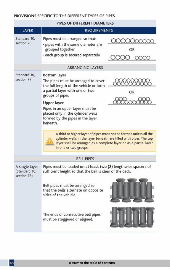
PROVISIONS SPECIFIC TO THE DIFFERENT TYPES OF PIPES
PIPES OF DIFFERENT DIAMETERS
LAYER REQUIREMENTS
Standard 10, section 76
Pipes must be arranged so that:
• pipes with the same diameter are grouped together;
• each group is secured separately.
ARRANGING LAYERS
Standard 10, section 77
Bottom layer
The pipes must be arranged to cover the full length of the vehicle or form a partial layer with one or two groups of pipes
Upper layer
Pipes in an upper layer must be placed only in the cylinder wells formed by the pipes in the layer beneath.
A third or higher layer of pipes must not be formed unless all the cylinder wells in the layer beneath are fi lled with pipes. The top layer shall be arranged as a complete layer or, as a partial layer in one or two groups.
BELL PIPES
A single layer (Standard 10, section 78)
Pipes must be loaded on at least two (2) lengthwise spacers of suffi cient height so that the bell is clear of the deck.
Bell pipes must be arranged so that the bells alternate on opposite sides of the vehicle.
The ends of consecutive bell pipes must be staggered or aligned.
OR
OR

49
PIPES OF DIFFERENT DIAMETERS
LAYER REQUIREMENTS
Upper layers (Standard 10, section 78)
Complete layerThe bells of the pipes in the bottom layer must be placed on the same side of the vehicle. The order must be inverted in the subsequent layer.
Partial layer The bells of the pipes in the bottom layer that do not support a pipe above must alternate on opposite sides of the vehicle.
SMALL PIPES (diameter smaller than or equal to 114.3 cm)
Single layer or bottom layer of stacked pipes (Standard 10, section 79)
Requirements for front and rear pipes:Pipes must be immobilized lengthwise at each end by:• blocking;• a vehicle end structure;• stakes;• a locked pipe unloader; OR• other equivalent means.
At least one (1) tiedown must:• run through the front pipes of
the lower layer AND• run rearward, at an angle of 45o with the horizontal,
where practical.
The same requirement applies to rear pipes, so as to apply a pressure on all pipes that are not located at either ends.
Requirements for the other pipes not located at the front or rear:The pipes must be held firmly in contact with the adjacent pipe and can be held in place by blocks, wedges or both.

50
SMALL PIPES (diameter smaller than or equal to 114.3 cm)
LAYER REQUIREMENTS
Second and subsequent layers (Standard 10, section 80)
Option 1
Pipes secured individually
A tiedown must run through each pipe.
Option 2
Pipes secured in groups
• One (1) chain or wire rope of 1.27 cm (0.5 inch) or two (2) chains or two (2) wire ropes of 0.95 cm (0.375 inch) must be placed lengthwise over the group of pipes.
• One (1) transverse tiedown must be used for every 3.04 m of cargo length.
Top layers (Standard 10, section 81)
Where the first pipe of a group in the top layer is not placed in the first cylinder well formed by the pipes at the front of the layer beneath, it must be secured by one (1) additional tiedown:
• running rearward at an angle of not more than 45° to the horizontal and passing through it;
OR• passing outside of the pipe and over the lengthwise tiedowns.
The same requirements apply to the last pipe of the upper layer.

51
LARGE PIPES (diameter greater than 114.3 cm)
LAYER REQUIREMENTS
All layers (Standard 10, section 82)
The front and rear pipes of a group of pipes must be immobilized by:• blocking; • wedges;• a vehicle end structure;• stakes;• a locked pipe unloader;
OR• other equivalent means.
Each pipe in the front half of the group of pipes, including the middle one where there is an odd number, must be secured by at least one (1) tiedown:
• passing through the pipe;
• running rearward at an angle of not more than 45° with the horizontal so as to be firmly in contact with the adjacent pipe.
The same requirements apply to each pipe of the rear half of a group of pipes.
Where the front or rear pipe in a group of pipes is not in contact with the vehicle’s end structure, stakes or other equivalent means, it must be secured by:
• at least two (2) tiedowns arranged according to the above-mentioned requirements.
Where the vehicle is transporting a single pipe, or several pipes that do not touch each other:
• the pipes must be secured as if they were the front or rear pipe in a group of pipes.

52
3.6 INTERMODAL CONTAINERS (Standard 10, Part 2, Division 6)
This section applies to intermodal containers:
• transported on container chassis vehicles;
• transported on other types of vehicles whose container is loaded or empty.
INTERMODAL CONTAINER
REQUIREMENTS
Loaded or empty container transported on a container chassis vehicle (Standard 10, section 84)
The container must be secured to the container chassis with integral locking devices that must restrain each lower corner of the container.
The front and the rear of the container must be independently secured.
Loaded container transported on other types of vehicles (Standard 10, section 85)
All the lower corners of the container must rest on the vehicle or be supported by a structure:
• capable of bearing the weight of the container;
• independently secured to the vehicle.
The container must be secured to the vehicle with four tiedowns, using one the following methods, or both:
• chains, wire ropes or integral locking devices that are fixed to all the lower corners of the container;
• four cross chains fixed to all upper corners of the container.
The front and the rear of the container must be independently secured.

53
INTERMODAL CONTAINER
REQUIREMENTS
Empty container transported on other types of vehicles (Standard 10, section 86)
All the lower corners of the container must rest on the vehicle or be supported by a structure:
• capable of bearing the weight of the container;
AND • independently secured to the vehicle.
The requirements are not necessary if:
• the container is balanced, positioned and stable on the vehicle before tiedowns are used
AND• the container does not overhang either the front or
rear of the vehicle by more than 1.5 m.
In all cases, the container must be secured against moving sideways, lengthwise or vertically in accordance with:
• the requirements applicable to loaded containers
OR• the general requirements of Section 2 of this guide
(Standard 10, section 22).

54
3.7 VEHICLES AS CARGO (Standard 10, Part 2, Division 7)
This section applies to the transportation of light vehicles, heavy vehicles and fl attened or crushed light vehicles.
VEHICLESTRANSPORTED
REQUIREMENTS
Light vehicles (Standard 10, section 88)
At least one (1) tiedown must be placed at the front and one (1) tiedown must be placed at the rear to prevent the vehicle from moving sideways, forward, rearward and vertically.
Tiedowns that are designed to attach to the structure of a light vehicle must be attached to the mounting points on the vehicle that are specifi cally designed for that purpose.
Tiedowns that are designed to fi t over or around the wheels of a light vehicle must restrain the vehicle from moving sideways, forward, rearward and vertically.
Additional tiedowns may be required to meet the general requirements set out in Section 2 of this guide. For example, the sum of the working load limit of the tiedowns must be at least 50% of the total cargo weight.
Machinery or equip-ment operating on wheels or tracks and whose weight is less than 4 500 kg are not considered light vehi-cles (see definition on p. 9) and must be secured according to the general require-ments of Section 2 or the requirements for heavy vehicles.

55
VEHICLES TRANSPORTED
REQUIREMENTS
Heavy vehicles and pieces of equipment or machinery operated on wheels or tracks (Standard 10, section 89)
At least four (4) tiedowns, each with a working load limit (WLL) of at least 2 268 kg must be attached:
• as close as practical to the front and rear
OR• to mounting points specifi cally designed for
that purpose.
The accessory equipment on a heavy vehicle (e.g. hydraulic shovels) must be completely lowered and secured to the vehicle, unless the equipment:
• can only move vertically
OR• is blocked or immobilized by the structure of the
vehicle or by a blocking mechanism built into the heavy vehicle.
Articulated vehicles must be restrained in a manner that prevents articulation during transport.
The working load limit of all the tiedowns must be at least 50% of the cargo weight.
To know which chain to use, consult the table in Section 2.1 of this guide (p. 17).

56
VEHICLES TRANSPORTED
REQUIREMENTS
Flattened or crushed light vehicles (Standard 10, sections 90 to 92)
These vehicles must be transported using vehicles which have one of the following four options:
Option 1 Containment walls or comparable structures on their four (4) sides, which:
• extend to the full height of the cargo
AND• prevent the cargo from moving forward, rearward
and sideways.
Option 2 Containment walls or comparable structures on three (3) sides, which:
• extend to the full height of the cargo
AND• prevent the cargo from moving forward, rearward
and sideways.
Each stack of vehicles must be secured by at least two (2) tiedowns, each having a WLL of at least 2 268 kg.
Option 3 Containment walls or comparable structures on two (2) sides, which:
• extend to the full height of the cargo
AND• prevent the cargo from moving forward, rearward
and to one side.
Each stack of vehicles must be secured by at least three (3) tiedowns each having a WLL of at least 2 268 kg.

57
VEHICLES TRANSPORTED
REQUIREMENTS
Flattened or crushed light vehicles (Standard 10, sections 90 to 92)
Option 4 The vehicle does not have containment walls:
• Each stack of vehicles must be secured by at least four (4) tiedowns each having a WLL of at least 2 268 kg.
The use of synthetic webbing to secure flattened or crushed light vehicles is prohibited. However it is allowed to use a tiedown consisting of a strap used in combination with a chain or cable if the strap does not exceed 15 cm above the platform and does not come in contact with the vehicles.
VEHICLES TRANSPORTED
REQUIREMENTS
Containment of loose parts of fl attened or crushed light vehicles (Standard 10, section 93)
In order to contain loose parts from fl attened or crushed vehicle, the vehicle transporting the cargo must be equipped with:
• structural walls;
• fl oors;
• sides or sideboards; or
• suitable covering material, alone or in combination.
The equipment must:
• extend to the full height of the cargo;
• prevent any loose part of the load from falling from the vehicle.

58
3.8 ROLL-ON/ROLL-OFF AND HOOK-LIFT CONTAINERS (Standard 10, Part 2, Division 8)
This section applies to the transportation of roll-on/roll-off containers and hook-lift containers. As a rule, these containers are transported on special vehicles equipped with an integral securement system.
VEHICLES ANDSECUREMENT TYPES
REQUIREMENTS
With or without an integral securement system (Standard 10, section 95)
Where a vehicle is not equipped with an integral securement system or does have such a system, but a front stop or lifting device is missing, damaged or not compatible with the securing devices on a container:
• the container must be secured using manually installed tiedowns.
A manually installed tiedown must provide the same level of securement as the component it replaces.
Without an integral securement system (Standard 10, section 96)
To prevent forward movements of the container, the container must be blocked:
• by the lifting device acting as a blocking structure
OR• by at least two (2) stops located on each side,
approximately at the same distance from the longitudinal axis of the container
OR• by a combination of these two means.

59
VEHICLES ANDSECUREMENT TYPES
REQUIREMENTS
Without an integral securement system (Standard 10, section 96)
The container must be secured:
To the front
• by the lifting device
OR• by another securing device (chains, straps, etc.) which
restrains against sideways and vertical movement.
To the rear
• by one (1) tiedown attached to the vehicle chassis and to both sides of the container;
OR• by two (2) tiedowns (one on each side) installed
lengthwise, each securing one side of the container to one of the vehicle’s side rails
OR• by two (2) hooks or equivalent mechanisms, securing both
sides of the container to the vehicle chassis (they must be as effective as the tiedowns mentioned for the previous mechanisms).
Devices used to secure the rear of a container must:
• be installed 2 m or less from the rear of the container AND• have a WLL of at least 2 268 kg.

60
3.9 BOULDERS (Standard 10, Part 2, Division 9)
This section applies to boulders:
• with a weight greater than 5 000 kg or a volume greater than 2 m3;
• transported on a fl atbed vehicle or in a vehicle whose sides are not designed and rated to contain such a cargo.
Boulders with a weight greater than 100 kg but less than 5 000 kg can also be secured in accordance with the provisions of this section.
A block of 2 m3 approximately corresponds to the dimensions of a box whose sides measure 1.26 m:
GENERAL PROVISIONS FOR BOULDERS
POSITIONING OF THE BOULDERS (Standard 10, sections 98 and 99)
TIEDOWNS
Each boulder must: • be placed with its fl attest or largest side down
AND• be supported on at least, two (2) pieces of
hardwood blocking:– with side dimensions equal to or greater than
8.9 cm x 8.9 cm;– that extend over the full width of the boulder;– that are placed as symmetrically as possible
under the boulder;– that support at least 3/4 of the length of
the boulder.
Only chains must be used to secure boulders.
The chains must be:
• in contact with the boulder;
• placed in valleys or notches across the top of the boulder;
• arranged so that it does not slide across the rock surface.

61
SPECIFIC PROVISIONS FOR BOULDERS
SHAPE OF BOULDERS TIEDOWNS REQUIRED
Cubic-shaped boulder (Standard 10, section 100)
Each boulder must be secured independently by at least two (2) chains:
• placed from one side of the vehicle to the other, parallel to each other
AND• placed as close as possible to the hardwood
blocking.
Non-cubic shaped boulder with a stable base (Standard 10, section 100)
Each boulder must be secured independently by at least two (2) chains:
• forming an “X” pattern over the boulder;
• passing over the centre of the boulder;
• attached to each other, where they intersect, by a shackle (ring linking two [2] chains) or another connecting device.

62
SPECIFIC PROVISIONS FOR BOULDERS
SHAPE OF BOULDERS TIEDOWNS REQUIRED
Non-cubic shaped boulder with a stable base (Standard 10, section 100)
Each boulder must be secured independently using the following two means:
• one (1) chain surrounding the top of the boulder
– placed between 1/2 and 2/3 of the height of the boulder;
– having a WLL of 1/2 the weight of the boulder
AND• four (4) chains, each attached to the surrounding
chain and to the vehicle so as to prevent the boulder from moving horizontally.
These chains must:
– have a WLL equal to or greater than 25% of the weight of the boulder;
– be placed, where practical, at an angle of not more than 45° from the horizontal.

63
3.10 BULK CARGO (CSSR, section 16)
This section applies to bulk cargo transported in a dump truck, container or other means of containment whose upper part is totally or partially open.
RESTRAINING METHOD COVERING SYSTEM REQUIREMENTS
The load must be restrained by a covering system consisting of:
• a tarpaulin
OR• a canvas
OR• any other type of
equivalent covering.
The covering system must:• cover at least any portion of the load that extends
beyond a reference point 15 cm below the top of the lowest wall;
• remain in direct contact with any portion of the load that extends beyond the nearest wall, unless the covering system is maintained above the load by bows secured to the vehicle;
• be exempt from tears or other damage in the section used for securement.
This section does not apply in the following situations, when a vehicle is transporting bulk cargo:
• The vehicle is crossing a public highway from a private road.
• The top of the load does not extend beyond the above-mentioned reference point.
• The vehicle is applying salt, sand, a mixture of salt and sand or other similar substance in connection with winter road maintenance.
• The vehicle is applying dust suppressants on a road.
• The vehicle is transporting snow, ice or other similar substance collected during a snow removal operation.
• The load extending beyond the reference point refer-red to in the second paragraph consists only of ele-ments exceeding 40 mm in 3 dimensions and the part of the cargo that is located on the periphery does not extend beyond the top of the lowest wall.

64
3.11 OTHER CARGO
For all other types of cargo that are not included in the specific provisions such as the transportation of rolled sod, cargo securement must be done in accordance with the general requirements set out in Section 2 of this guide.

65
APPENDIX
CONVERSION OF THE UNITS USED IN THIS GUIDE
The imperial units were rounded off to facilitate comprehension. Only the metric units have the force of law.
Size and dimensions
Millime-ters (mm)
Inches (in.)
Centime-ters (cm)
Inches (in.)
Meters (m)
Feet (ft.)
10 3/8 0.95 3/8 0.6 211 7/16 1.27 0.5 1.25 413 0.5 8.9 3.5 1.5 525 1 10 4 1.52 538 1.5 14 5.5 1.83 640 2 15 6 1.85 6
20.3 8 2.44 8114.3 45 3.04 10122 48 3.66 12
4.9 16
Weight
Kilograms (kg)
Pounds (lb.)
100 220500 1 100900 1 985
2 000 4 4102 268 5 0002 990 6 5923 000 6 6143 970 8 7524 000 8 8184 500 9 9205 000 11 0235 130 11 3106 500 14 3306 800 14 991
15 000 33 069
Volume
2 m3 = 70.6 ft3

For additional information: www.transports.gouv.qc.ca
Direction de la normalisation technique

