carpenter and paterson ltd - catalogue · pdf fileancillaryequipment...
TRANSCRIPT

Ancillary Equipment
FIG. 381 SLIDING SUPPORT/FIG. 382 SLIDING GUIDE
Nom PipeSize
PipeO/D B C
MaxMvt G K L Cut From
MaxLoadKg
20 26.6 114 50 100 60 150 Plate
23025 33.4 117 50 100 60 150 Plate32 42.1 121 50 100 60 150 Plate40 48.3 125 50 100 60 150 Plate50 60.3 131 50 100 60 150 Plate65 76.1 138 50 100 100 150 203x102x23 U/B
45080 88.9 145 50 100 100 150 203x102x23 U/B90 101.6 151 50 100 100 150 203x102x23 U/B100 114.3 158 65 90 100 150 203x102x23 U/B125 139.7 170 65 90 100 150 203x102x23 U/B
800150 168.3 185 65 90 100 150 203x102x23 U/B200 219.1 210 80 100 134 200 203x133x30 U/B
2900250 273.0 237 80 100 134 200 203x133x30 U/B300 323.9 262 80 100 205 200 203x203x60 U/C 5900350 355.6 278 80 150 205 250 203x203x60 U/C
6500400 406.4 304 80 150 205 250 203x203x60 U/C450 457.0 329 80 145 254 250 254x254x73 U/C
7900500 508.0 354 90 180 305 300 305x305x97 U/C550 558.8 380 90 180 305 300 305x305x97 U/C 8700600 610.0 405 90 180 305 300 305x305x97 U/C 9200
FIG. 381
FIG. 382
Material - Carbon Steel.
Dimensions may be modified to suit specific applications, andlow friction bearing surfaces applied, i.e. P. T. F. E.
SLIDING SUPPORT (WELDED TYPE)
For Pipework up to and Including 150NS For Pipework 200NS and above
SLIDING GUIDE (WELDED TYPE)
For Pipework up to and Including 150NS For Pipework 200NS and above
04/1086
1010101010101010121212121215151515202020Welded on
3 sides Welded on3 sides
Supporting Steelwork
1mm clearall round
Supporting Steelwork
1mm clearall round
Insulation

Ancillary Equipment
PIPE SADDLE CLAMPED FOR UP TO AND INCLUDING 150NB
Max LoadKg
230 450 800
Nom PipeSize
20 25 32 40 50 65 80 90 100 125 150
A 114 117 121 124 130 138 144 151 157 170 184B 60 60 60 60 60 100 100 100 100 100 100
L 150 150 150 150 150 150 150 150 150 150 150M 102 114 126 140 152 178 192 204 238 276 314
PIPE SADDLE CLAMPED FOR PIPEWORK 200NB & OVER
Max LoadKg 2900 5900 6500 7900 8700 9200
Nom PipeSize 200 250 300 350 400 450 500 550 600
A 210 237 262 278 303 329 354 379 405B 134 134 205 205 205 254 305 305 305L 200 200 200 250 250 250 300 300 300
M 378 452 504 542 592 668 720 804 864
FIG. 384-1
FIG. 384-2
Material - Carbon Steel.
When ordering specify:Figure No.Nominal Pipe Size
Material - Carbon Steel.
When ordering specify:Figure No.Nominal Pipe Size
04/1087
Ancillary Equipment
Material:-Range A Carbon Steel (-20 to 100°C)Range B Carbon Steel (101 to 400°C)Range C Alloy Steel
When ordering specify:Figure No.RangeNominal Pipe SizeInsulation Thickness
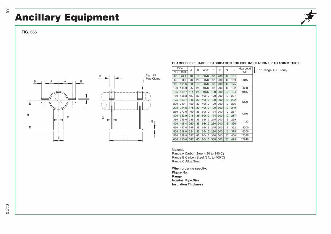
FIG. 385
CLAMPED PIPE SADDLE FABRICATION FOR PIPE INSULATION UP TO 100MM THICK
PipeA B WxT E F G H
Max LoadKgNB O/D
65 76.1 70 19 30x6 62 200 6 161234580 88.9 76 20 30x6 62 200 6 169
90 101.6 83 19 30x6 62 200 6 175
100 114.3 95 24 40x6 62 200 6 182 2650125 139.7 114 24 40x6 120 300 10 184 4075150 168.3 127 30 40x10 120 300 10 207
5200175 193.7 146 30 40x10 120 300 10 222200 219.1 159 30 40x10 120 300 10 236225 244.5 178 30 40x10 120 300 10 249
250 273.0 190 36 50x12 174 300 12 2577240
300 323.9 216 36 50x12 174 300 12 287350 355.6 235 36 65x12 215 300 16 299
11420400 406.4 260 36 65x12 230 300 16 326450 457.0 298 36 65x15 245 300 16 352 15300500 508.0 324 36 65x15 280 300 16 375 16300
550 558.8 357 45 80x15 330 300 20 400 17025600 610.0 387 45 80x15 330 300 20 425 17840
For Range A & B only{
04/1088
Material:-Range A Carbon Steel (-20 to 340oC)Range B Carbon Steel (341 to 400oC)Range C Alloy Steel

Ancillary Equipment
Material:-Range A Carbon Steel (-20 to 100°C)Range B Carbon Steel (101 to 400°C)Range C Alloy Steel
When ordering specify:Figure No.RangeNominal Pipe SizeInsulation Thickness
FIG. 386
CLAMPED PIPE SADDLE FABRICATION FOR PIPE INSULATION 100-200MM THICK
PipeA B WxT E F G H
Max LoadKgNB O/D
65 76.1 70 19 30x6 66 200 8 261367080 88.9 76 20 30x6 66 200 8 269
90 101.6 83 19 30x6 66 200 8 275
100 114.3 95 24 40x6 66 200 8 282 3870125 139.7 114 24 40x6 124 300 12 284 6110150 168.3 127 30 40x10 124 300 12 307
8360175 193.7 146 30 40x10 124 300 12 322200 219.1 159 30 40x10 124 300 12 336225 244.5 178 30 40x10 124 300 12 349
250 273.0 190 36 50x12 182 300 16 35713350
300 323.9 216 36 50x12 182 300 16 387350 355.6 235 36 65x12 220 300 20 399 15290
400 406.4 260 36 65x12 245 300 20 426 16310450 457.0 298 36 65x15 255 300 20 452 17840500 508.0 324 36 65x15 290 300 20 475 20385
550 558.5 357 45 80x15 350 300 25 500 21410600 610.0 387 45 80x15 350 300 25 525 22935
For Range A & B only{
04/1089
Material:-Range A Carbon Steel (-20 to 340oC)Range B Carbon Steel (341 to 400oC)Range C Alloy Steel

Ancillary Equipment
Material:-Range A Carbon Steel (-20 to 100°C)Range B Carbon Steel (101 to 400°C)Range C Alloy Steel
When ordering specify:Figure No.RangeNominal Pipe SizeInsulation Thickness
FIG. 387
PIPE SADDLE FABRICATION FOR PIPE INSULATION UP TO 100MM THICK
PipeWxT B C D E
Max LoadKgNB O/D
65 76.1 30x6 62 200 6 161234580 88.9 30x6 62 200 6 169
90 101.6 30x6 62 200 6 175
100 114.3 40x6 62 200 6 182 2650125 139.7 40x6 120 300 10 184 4075150 168.3 40x10 120 300 10 207
5200175 193.7 40x10 120 300 10 222200 219.1 40x10 120 300 10 236225 244.5 40x10 120 300 10 249
250 273.0 50x12 174 300 12 2577240
300 323.9 50x12 174 300 12 287350 355.6 65x12 215 300 16 299
11420400 406.4 65x12 230 300 16 326450 457.0 65x15 245 300 16 352 15300500 508.0 65x15 280 300 16 375 16300
550 558.8 80x15 330 300 20 400 17025600 610.0 80x15 330 300 20 425 17840
For Range A & B only{
04/1090
Material:-Range A Carbon Steel (-20 to 340oC)Range B Carbon Steel (341 to 400oC)Range C Alloy Steel

Ancillary Equipment
Material:-Range A Carbon Steel (-20 to 100°C)Range B Carbon Steel (101 to 400°C)Range C Alloy Steel
When ordering specify:Figure No.RangeNominal Pipe SizeInsulation Thickness
PIPE SADDLE FABRICATION FOR PIPE INSULATION 100-200MM THICK
PipeWxT B C D E
Max LoadKgNB O/D
65 76.1 30x6 66 200 8 261367080 88.9 30x6 66 200 8 269
90 101.6 30x6 66 200 8 275
100 114.3 40x6 66 200 8 282 3870125 139.7 40x6 124 300 12 284 6110150 168.3 40x10 124 300 12 307
8360175 193.7 40x10 124 300 12 322200 219.1 40x10 124 300 12 336225 244.5 40x10 124 300 12 349
250 273.0 50x12 182 300 16 35713350
300 323.9 50x12 182 300 16 387350 355.6 65x12 220 300 20 399 15290
400 406.4 65x12 245 300 20 426 16310450 457.0 65x15 255 300 20 452 17840500 508.0 65x15 290 300 20 475 20385
550 558.8 80x15 350 300 25 500 21410600 610.0 80x15 350 300 25 525 22935
FIG. 388
For Range A & B only{
04/1091
Material:-Range A Carbon Steel (-20 to 340oC)Range B Carbon Steel (341 to 400oC)Range C Alloy Steel

Ancillary EquipmentMaximum Load - 700 Kg.
Material - Carbon Steel.
When ordering specify:Figure No.Size
FIG. 84
FIG. 139
FIG. 150
FIG. 159
MEDIUM WELDED STEEL BRACKET
Size A B C D E F G H J L0 305 465 395 30 65 110 40 40 5 22
1 460 615 545 30 65 130 50 50 6 222 610 770 700 30 65 130 50 50 6 22
Maximum Load - 1360 Kg.
Material - Carbon Steel.
When ordering specify:Figure No.Size
HEAVY WELDED STEEL BRACKET
Size A B C D E F G H J K L0 305 470 390 30 70 110 40 40 6 - 22
1 460 615 545 35 70 130 50 50 8 70 222 610 760 700 40 70 130 50 65 8 65 263 765 925 845 40 80 130 50 65 8 65 26
4 915 1075 990 40 80 160 65 100 10 90 265 1065 1270 1170 40 90 160 65 100 10 90 26
Maximum Load - 230 Kg.
Material - Carbon Steel.
When ordering specify:Figure No.Size
STEEL BRACKET
Size A B C D G H FlatE
1 305 460 380 14 76 30 100x102 460 610 535 14 76 30 100x10
3 610 760 685 18 76 30 100x124 760 915 840 18 76 30 100x125 915 1070 990 22 76 30 100x15
STEEL BRACKET
Size A B C D HAngleF
PlateE
Max LoadKg
1 305 305 230 14 50 50x50x6 6 310
2 460 460 380 14 50 50x50x6 6 3203 610 610 520 18 50 50x50x8 6 5504 760 760 645 18 65 60x60x10 6 600
5 915 915 780 22 75 80x80x10 10 850
Material - Carbon Steel.
When ordering specify:Figure No.SizeDistance from wall to centre of pipe (Dim. X)Hole Size J
04/1092

Ancillary EquipmentFIG. 1007
PIPE GUIDE
Size A B C D E F G H J T1 95 152 157 55 100 200 100 M12 150 6
2 110 180 183 70 130 200 100 M12 150 63 125 209 211 85 140 200 100 M12 150 84 150 260 262 110 160 200 100 M12 150 8
5 175 312 316 135 185 200 100 M16 150 106 200 378 398 210 280 200 100 M16 150 107 225 428 460 240 300 300 150 M20 230 15
8 250 479 511 280 340 300 150 M20 230 159 280 534 562 340 400 300 150 M24 230 2010 305 584 612 380 460 300 150 M24 230 20
11 330 635 663 400 500 300 150 M24 230 20
Material - Carbon Steel.
Sleeve can be made longer for extreme travel conditions.Sleeve can be split at plus or minus 45 degrees if minimumDimension C is required for clearance.
S.W. Loads to suit specific applications.
When ordering specify:Figure No.Nominal Pipe SizeThickness of InsulationGuide Size No.
SizeThickness of Insulation
NominalPipeSizes
25 38 50 63 75 1001 0-252 32-50 25
3 65 32-50 254 80-100 65-80 32-65 25-50 255 125-150 100-125 80-100 65-80 32-65 25
6 200 150 125-150 100-125 80-100 32-657 250 200 200 150 125-150 80-1008 300 250 250 200 200 125-150
9 350 300-350 300 250 250 20010 400 400 350 300 300 25011 400 400 350 300
04/1093
125
-