carrier commercial refrigeration, inc. service
TRANSCRIPT
SERVICE &INSTALLATION
MANUAL
MEDIUM TEMPERATURE
VERTICAL REFRIGERATORS
51-1337-0201/03
CARRIER COMMERCIAL REFRIGERATION, INC.
Providing BEVERAGE-AIR • FRIGIDAIRE • KELVINATOR • UNIVERSAL NOLIN Products/Services

If additional information is necessary, call the factory.
Our toll free number is 1-800-684-1199. Technical assis-tance engineers are willing to assist you in any way possi-ble. Office hours are from 8:00 a.m. to 5:30 p.m., EasternStandard Time.
Important information is contained in this manual which shouldbe retained in a convenient location for future reference.
All data and information in this manual is subject to change without notice.
Manual effective for models produced January, 2003.Starting serial number .
PART NO. MODELS STYLE CONDENSER SPECIAL USE52-1923-01 BT30RF- EXPR SOLID ONE DOOR TOP MOUNT EXPLOSION PROOF52-1958-02 BT30RF-FMS SOLID ONE DOOR TOP MOUNT FLAMMABLE MAT'L STORAGE52-1993-33 BT30RG-4.1 GLASS ONE DOOR TOP MOUNT SCIENTIFIC GENERAL PURPOSE52-1993-34 BT30RGCH-4.1 GLASS ONE DOOR TOP MOUNT CHROMATOGRAPHY52-1993-35 BT30RS-4.1 SOLID ONE DOOR TOP MOUNT SCIENTIFIC GENERAL PURPOSE52-1993-29 BT30RSFMS-4.1 SOLID ONE DOOR TOP MOUNT FLAMMABLE MAT'L STORAGE52-1993-36 BT50RG-4.1 GLASS TWO DOOR TOP MOUNT SCIENTIFIC GENERAL PURPOSE52-1993-37 BT50RGCH-4.1 GLASS TWO DOOR TOP MOUNT CHROMATOGRAPHY52-1993-38 BT50RS-4.1 SOLID TWO DOOR TOP MOUNT SCIENTIFIC GENERAL PURPOSE52-1993-30 BT50RSFMS-4.1 SOLID TWO DOOR TOP MOUNT FLAMMABLE MAT'L STORAGE52-1993-39 BT80RG-4.1 GLASS THREE DOOR TOP MOUNT SCIENTIFIC GENERAL PURPOSE52-1993-32 ST260RIR-4.1 SOLID ONE DOOR TOP MOUNT INCUBATOR52-1993-41 ST30RGBB-4.1 GLASS ONE DOOR TOP MOUNT BLOOD STORAGE52-1993-42 ST50RGBB-4.1 GLASS TWO DOOR TOP MOUNT BLOOD STORAGE52-1991-64 T30MGP-4.1 GLASS ONE DOOR TOP MOUNT52-1991-65 T30MSP-4.1 SOLID ONE DOOR TOP MOUNT52-1991-66 T50MGP-4.1 GLASS TWO DOOR TOP MOUNT52-1997-36 T50MGPR-4.1 GLASS TWO DOOR TOP MOUNT52-1991-67 T50MSP-4.1 SOLID TWO DOOR TOP MOUNT52-1991-68 T80MGP-4.1 GLASS THREE DOOR TOP MOUNT52-1997-37 T80MGPR-4.1 GLASS THREE DOOR TOP MOUNT52-1992-32 UMG30BS-4.1 GLASS ONE DOOR BOTTOM MOUNT52-1992-33 UMG50BS-4.1 GLASS TWO DOOR BOTTOM MOUNT52-1997-34 UMG50RS-4.1 GLASS TWO DOOR BOTTOM MOUNT52-1992-34 UMG80BS-4.1 GLASS THREE DOOR BOTTOM MOUNT52-1997-35 UMG80RS-4.1 GLASS THREE DOOR BOTTOM MOUNT52-1992-35 UMH30BS-4.1 GLASS ONE DOOR BOTTOM MOUNT HEATED DOORS52-1992-36 UMH50BS-4.1 GLASS TWO DOOR BOTTOM MOUNT HEATED DOORS52-1992-37 UMH80BS-4.1 GLASS THREE DOOR BOTTOM MOUNT HEATED DOORS
MODEL DESIGNATION INFORMATION

TABLE OF CONTENTS-MED. TEMP. VERTICAL
MODEL CODES EXAMPLES..................................................2
HANDLING & INSTALLATION ..............................................4
TOP MOUNT, GLASS PULL DOOR (1-,2-,& 3-DR MODELS)Dimensional Drawings ..........................................................6Refrigerator Specifications....................................................7
BOTTOM MOUNT, GLASS PULL DOOR (1-, 2-, 3-DR MODELS)Dimensional Drawings ..........................................................8Refrigerator Specifications....................................................9
TOP MOUNT, SOLID PULL DOOR (1 & 2-DR MODELS)Dimensional Drawings & Specifications ............................10
MAINTENANCE & REPAIR ......................................37
ELECTRICAL & REFRIGERATION INFORMATIONMedium Temperature Glass & Solid 1 Door ......................15Medium Temperature Glass & Solid 2 Door ......................16Medium Temperature Glass 3 Door ....................................17Medium Temperature Solid 1 & 2 Door FMS......................17
ELECTRICAL & REFRIGERATION INFORMATIONBT30RF-FMSMedium Temperature Solid 1 Door ....................................65
ELECTRICAL & REFRIGERATION INFORMATIONBT30RF-EXPRMedium Temperature Solid 1 Door Refrigerator/Freezer ....69
ELECTRICAL & REFRIGERATION INFORMATIONST260RI, ST260RIRIncubator ............................................................................81
TROUBLESHOOTING ................................................93
COMPONENT IDENTIFICATION ........................100
PARTS LIST ....................................................................109
TABLE OF CONTENTS 1

Medium Temperature Vertical RefrigeratorsIntroduction
These refrigerators have been designed to maintain a medi-um temperature environment. These multi-purpose refrigera-tors are available in one, two, and three-door solid or glassdoor models.
Except for routine cleaning, these medium temperature cabi-nets will require little maintenance. In the unusual event thatrepair should be necessary, this manual presents informationthat is helpful in maintaining, diagnosing, and repairing thesecabinets.
2 INTRODUCTION

MODEL CODES – KELVINATOR & KELVINATOR SCIENTIFIC 3
MODEL CODES
Kelvinator Model Example: T30LGPR-4
T 30 L G P R -4
T = Top MountB = Bottom MountFS = Food Service
30, 50, 80 - Cubic Feet
L = Low TempM - Medium TempH = Hardening Cabinet
G= Glass DoorS = Solid Door
P = Pull DoorS = Sliding DoorQ = Quadrant Pull Door
R = RemoteE = ExportET = Export TransformerCustomer Variations:
BR = Baskin RobbinsDQ = Dairy QueenDQL = Dairy Queen Light Duty
4 = Revision Level
Kelvinator Scientific Model Example: ESTL50RSFMS-4
E S TL 50 R S FMS -4
E = ExportET = Export (Transformer)
S = ScientificB = Base Scientific
T = Top MountB = Bottom MountC = ChestL = Hardening Cabinet
30, 50, 80 = Cubic Feet
F = FreezerR = Refrigerator
G = Glass DoorS = Solid DoorI = Incubator (Solid Door)
FMS = Flammable Material StorageCH = ChromatographyBB = Blood BankEXPR = Explosion ProofR = Recorder on IncubatorCustomer Variations:
XXX
4 = Revision Level

4 MODEL CODES – UN
MODEL CODES
Universal Nolin Model Example: UMG50BS-4
U M G 50 B S -4
U = UprightS = Scientific (upright)
L = Low Temp.M = Med Temp.
H = Heated Glass (medium temp.)G = GlassS = SolidO = OpenT = Sliding Glass Door (track)
30, 50, 80 =Cubic Feet
R = Remote on Bottom Mounted UprightU - Remote on Top Mounted UprightT = Top Mounted CompressorB = Bottom Mounted CompressorS = Single Facing (sliders)D = Double Facing
S = 115V / 60 Hz.D = 208/230V / 60 Hz. / 1 Ph.P = 208V / 60 Hz. / 3 Ph.T = TransformerF = 220V / 50 Hz.
4 = Revision Level

SECTION I – HANDLING & INSTALLATION
HANDLING & INSTALLATION 5
FREIGHT DAMAGES & SHORTAGESThe cabinet was inspected andpackaged at the factory, and should
arrive in excellent condition. The transportation compa-ny or other parties involved in the shipment are respon-sible for loss and/or damage. Always make an inspec-tion before and after uncrating. Inspect the cratedunit(s) before locating (preferably at the point ofunloading by the transportation company).
INSPECTING FOR DAMAGESAlways use care when removing shippingtape, blocks, pads, hardware or other mate-
rial until you are satisfied that the unit is completelyoperational. Contact the factory if technical assistanceis required.
Check the cartons or containers. If these are damagedin any way, open them and inspect the contents in thedriver’s presence. If damage is detected:
1. Have the driver note the nature and extent of thedamage on the freight bill.
2. Notify the transportation company at once to requestan inspection. Carrier claim policies usually requireinspections to be made within 15 days of delivery.
3. If damage is noticed, file a claim with the transporta-tion company.
FILING A CLAIMFile a claim for loss at once with the transportation com-pany for:
A. A cash adjustment; B. Repairs; or C. Replacement.
When filing your claim, retain all packaging materialsand receipts.
HANDLING THE CABINETThe refrigeration system of the cabinet isdesigned to operate with the cabinet located
on a level surface. Do not tilt the cabinet more than10° to any side. If the cabinet must be tilted on anangle for handling or moving purposes, allow it to sit inan upright position 30 minutes prior to starting.
CHOOSING A LOCATIONThis model cabinet should be situated to allow proper aircirculation. These cabinets require a 2" minimum clear-ance behind for proper air circulation.
The cabinet must be installed on sturdy, solid, level floor.
The cabinet must be located so it can be plugged into aproperly grounded three-prong electrical outlet of 115volt, 60 hz. The electrical outlet should not be controlledby a wall switch which might be turned off accidentally.
UNCRATING THE CABINETThe cabinet should be moved as close as possible to theoperating location before removing crate base. Be sureto follow the steps in the “INSPECTING FOR DAM-AGES” instructions.
INSTALLING THE CABINET(Models with Top Mounted Compressor)Whenever possible leave the crate base on the cabinetuntil it is moved close to the final position.When it is nec-essary to move the cabinet through a doorway, it may benecessary to remove the crate base.
Wood runners are provided on the underside of the cab-inet for ease in sliding. These runners should be leftattached to the cabinet when the crate base is removedand should remain attached until after the legs areinstalled. The cabinet can then be pushed around moreeasily without scratching the floor. The runners also pre-vent damage to the electrical receptacle and conden-sate pan hardware on the cabinet bottom.
After the cabinet has been moved to the approximatefinal location, remove the package containing the legsfrom the cabinet interior. Tape the doors to preventaccidental opening when handling. Raise the sides ofthe cabinet high enough to mount the legs at the loca-tions provided on the bottom of the cabinet.
IMPORTANT:
AFTER REMOVALOF WOOD RUN-NER, REPLACEBOLT “A” INTOLEG MOUNTINGBRACKETS. THISIS EXTREMELYIMPORTANT TOTHE SECUREATTACHMENT OFTHE CABINETLEG. THEREMUST BE FOUR(4) BOLTSSECURING EACHLEG.
Level the cabinet by means of the leg adjustments.Cabinet doors are self-closing, and the cabinet must belevel to operate properly.
NOTE:
IMPORTANT:
NOTE:

6 HANDLING & INSTALLATION
CONDENSATE PANINSTALLATION INSTRUCTIONS
MAKE SURE THE CABINET IS DISCONNECTEDFROM ITS POWER SOURCE
1. Remove and discard protective cover over electricalreceptacle on bottom of cabinet
2. Bend down front part of housing. (See above.)
3. Insert condensate evaporator pan assembly into the slidesupports on the underside of the cabinet by pushingtoward back of cabinet until it stops.
4. Plug supply cord into receptacle in underside of cabinet.
5. Bend up front part of housing. Line up slot with rivnut incabinet bottom and insert thumbscrew through slot ontorivnut in cabinet bottom. Insert thumb screw through slotonto rivnut and tighten.
6. The assembly will now operate when power is supplied tothe cabinet.
7. Inspect rear of cabinet to ensure that the drain line fromthe evaporator is properly positioned over the conden-sate pan.
On top mount models, allow a minimum of twelve (12) inch-es between the top of the cabinet and ceiling and two (2)inches from the back of the cabinet to the wall.
(Models with Bottom Mounted Compressor)Remove the crate base mounting clips located behind thefront grill. Slide the cabinet forward on the crate base to clearthe rear mounting clips.
After removing the crate base, move the cabinet into loca-tion. Make sure the cabinet is level to ensure operation of the“self-closing” doors.
Allow a minimum of two (2) inches between the back of thecabinet and the wall for proper air circulation through thecondensing unit.
CABINET STARTUPOnce the cabinet has been located in its permanent locationand the proper power and grounding have been provided,the following items must be checked or completed:
1. Cut and remove the compressor hold-down band (ifapplicable) so the compressor “floats” freely.
2. Check for traces of oil on the compressor pan which couldmean a broken or leaking refrigeration line.
2. UNDER NO CIRCUMSTANCE SHOULD THE COM-PRESSOR BE STARTED WHEN OIL IS PRESENTUNTIL INSPECTED BY A SERVICE TECHNICIAN.
3. INSPECT THE FACTORY WIRING FOR TERMINALSTHAT MIGHT HAVE VIBRATED LOOSE IN SHIPPING.TIGHTEN ALL SCREW-TYPE TERMINALS.
4. Check the refrigeration lines to see that they are “free”and no damage was done during shipping.
5. Check fan blade(s) for “free” operation.
6. Turn on the main power switch. Once the compressorstarts, the voltage should be checked at the compressorterminals to determine if there is proper voltage to thecompressor.The voltage should not exceed 10% above orbelow the rated compressor voltage.
EXAMPLE: If the voltage reads 115 volts with no load and itdrops below 103 volts when the compressor starts, itmay indicate that the supply wiring is too small or thatthe wire run is too long.
7. Make sure that the drain line has not been dislodged orbroken during shipping and that the drain trap termi-nates properly in the condensate pan or floor drain.(See Condensate Pan on top mounted compressor.)
8. Listen for any unusual noise such as lines vibrating, etc.Correct problem by tightening screws, slightly bendingtubing, etc.
9. Check proper tension on doors. (See Door TorqueAdjustment.)
10. Cabinet should not be loaded with product until cabinethas operated for 24 hours and reached desirable stor-age temperature.
THERMOSTAT SETTINGSThe refrigerator is shipped from the factory with a thermostatsetting of approximately the mid-point of the operatingrange. Final thermostat setting must be made in the field.
Allow the cabinet to operate until the compressor cycles onthe thermostat. The normal operating temperature range forthe refrigerator is:
32°F to 55°F (0°C to 13°C)
NOTE: DO NOT OPERATE THE CABINET WITH THERMO-STAT SETTINGS BELOW 32°F (0°C).
The thermostat is easily adjusted with a standard screwdriv-er. The thermostat has settings 1 through 7, turn the ther-mostat to a higher number to lower the cabinet temperature.
The thermostat is located behind the evaporator front grilland can be adjusted through the grill. On some models thethermostat is located in the electrical box at the top of thecabinet.
SCIENTIFIC CONTROL ANDANNUNCIATOR PANELSCabinets for Scientific use may be equipped with a variety ofoptional control, alarm, and recorder devices. Each cabinetis shipped with the appropriate operators manual for thedevice installed on the cabinet. These operator manuals per-tain to the set-up and basic operation of the control paneldevices. For more comprehensive operation, repair, andmaintenance information refer to the control panel servicemanual part number 51-0170-01.
FIGURE 2

GROUNDING INSTRUCTIONS/SERIAL RATING PLATES 7
GROUNDING INSTRUCTIONSThis appliance is equipped with a three-prong(grounding) plug for your protection against shockhazards. The appliance should be plugged directly intoa properly grounded three-prong receptacle.
Where a two-prong wall receptacle is encountered, itmust be replaced with a properly grounded threeprong receptacle in accordance with the NationalElectrical Code and local codes and ordinances. Thework must be done by a licensed electrician.
IMPORTANTDo not under any circumstances cut or remove
the round grounding prong from the equipment plug.
WARNINGConsult a licensed electrician if you have any doubt about the grounding of your wall receptacle. Only a licensed electrician can determine the polarization of your wall receptacle. Only a properly installed three-prongedwall receptacle assures the proper polarization with the equipment plug.
20 Amp
15 Amp
SERIAL RATING PLATESSerial Number Rating Plates on each vertical cabinetare located on the inside upper left hand corner. Thisplate contains all technical data necessary to the oper-
ation of the cabinet. Warranty administration is basedon the serial number as printed on the rating plate.

Medium Temperature, Top Mount, Glass Pull DoorRefrigerators Dimensional Drawings
8 TOP MOUNT GLASS PULL DOOR DIMENSIONAL DRAWINGS
SIDE VIEW
261/4
INTERIOR
263/4
GLASS
61GLASS833/4
6
52
471/4
INTERIOR
215/8
GLASSTYP.
61GLASSTYP.
361/4
343/4
33
605/8
INTERIOR
295/8
INTERIOR
6
833/4
61GLASS
TYP.
215/8
GLASSTYP.
78
731/4
INTERIOR
31

Medium Temperature, Top Mount, Glass Pull DoorRefrigerators Specifications
TOP MOUNT GLASS DOOR REFRIGERATOR SPECIFICATIONS 9
Specification 1-Door 2-Door 3-DoorCompressor Mount Top Top Top
Temperature Range 32° to 55° (0° to 13°C) 32° to 55° (0° to 13°C) 32° to 55° (0° to 13°C)
Number of Doors 1 2 3
Door Construction Double Pane Double Pane Double Pane
Hinge Type Torsion Bar Torsion Bar Torsion Bar
Insulation - CFC-Free Foam-in-Place Urethane Foam-in-Place Urethane Foam-in-Place Urethane
Wall Thickness 2 3/8" 2 3/8" 2 3/8"
Capacity - Gross 27.3 ft.3
49.1 ft.3
76.2 ft.3
Shipping Weight (Approx.) 470 lbs. 640 lbs. 870 lbs.
Compressor BTUH/-10°F Evap. 2400 5400 5400
Condenser Type Fin & Tube Forced Air Fin & Tube Forced Air Fin & Tube Forced Air
Evaporator Type Fin & Tube Forced Air Fin & Tube Forced Air Fin & Tube Forced Air
Refrigerant Type R-404A R-404A R-404A
Refrigerant Control Expansion Valve Expansion Valve Expansion Valve
Amp Rating 9.5 12.1 14.5
11.2 BT30RG & ST30RGBB 13.8 BT50RG & ST50RGBB 16.0 BG80RG
13.2 BT30RGCH 15.8 BT50RGCH
Electrical Specs. (V / Hz / Ph) 115 / 60 / 1 115 / 60 / 1 115 / 60 / 1
NSF NSF7 NSF7 NSF7
UL & CSA Listed Yes Yes Yes
Interior Finish Baked Enamel, Coved Corners Baked Enamel, Coved Corners Baked Enamel, Coved Corners
Exterior Finish Baked Enamel Baked Enamel Baked Enamel
Lighting 2 Insul. 1500 Milliamp Fluor. Lamps 3 Insul. 1500 Milliamp Fluor. Lamps 4 Insul. 1500 Milliamp Fluor. Lamps
Electrical Information 15 Amp Service Cord 20 Amp Service Cord 20 Amp Service Cordw/NEMA 5-15P Plug w/NEMA 5-20 Plug w/NEMA 5-20P Plug20 Amp Cord BT30RGCHw/NEMA 5-20P Plug

Medium Temperature, Bottom Mount, Glass Pull Door Refrigerators Dimensional Drawings
10 BOTTOM MOUNT DIMENSIONAL DRAWINGS
GLASS
INTERIOR
215/8
GLASSTYP.
INTERIOR
78
SIDE VIEW
31
26 1/4
GLASS263/4
61
793/4
52
471/4
61GLASSTYP.
361/4
343/4
33
605/8
INTERIOR
295/8
INTERIOR
731/4
INTERIOR
215/8
GLASSTYP.
61GLASSTYP.
793/4

Medium Temperature, Bottom Mount, Glass Pull Door Refrigerators Specifications
BOTTOM MOUNT REFRIGERATOR SPECIFICATIONS 11
Specification 1-Door 2-Door 3-DoorCompressor Mount Bottom Bottom Bottom
Temperature Range 32° to 55° (0° to 13°C) 32° to 55° (0° to 13°C) 32° to 55° (0° to 13°C)
Number of Doors 1 2 3
Door Construction Double Pane Double Pane Double Pane
Hinge Type Torsion Bar Torsion Bar Torsion Bar
Insulation - CFC-Free Foam-in-Place Urethane Foam-in-Place Urethane Foam-in-Place Urethane
Wall Thickness 2 3/8" 2 3/8" 2 3/8"
Capacity - Gross 27.3 ft.3
49.1 ft.3
76.2 ft.3
Shipping Weight (Approx.) 488 lbs. 640 lbs. 724 lbs.
Compressor BTUH/-10°F Evap. 2400 5400 5400
Condenser Type Fin & Tube Forced Air Fin & Tube Forced Air Fin & Tube Forced Air
Evaporator Type Fin & Tube Forced Air Fin & Tube Forced Air Fin & Tube Forced Air
Refrigerant Type R-404A R-404A R-404A
Refrigerant Control Expansion Valve Expansion Valve Expansion Valve
Amp Rating 9.5 12.1 14.5
Electrical Specs. (V / Hz / Ph) 115 / 60 / 1 115 / 60 / 1 115 / 60 / 1
NSF NSF7 NSF7 NSF7
UL & CSA Listed Yes Yes Yes
Interior Finish Baked Enamel, Coved Corners Baked Enamel, Coved Corners Baked Enamel, Coved Corners
Exterior Finish Baked Enamel Baked Enamel Baked Enamel
Lighting 2 Insul. 1500 Milliamp Fluor. Lamps 3 Insul. 1500 Milliamp Fluor. Lamps 4 Insul. 1500 Milliamp Fluor. Lamps
Electrical Information 15 Amp Service Cord 20 Amp Service Cord 20 Amp Service Cordw/NEMA 5-15P Plug w/NEMA 5-20P Plug w/NEMA 5-20P Plug

12 TOP MOUNT SOLID DOOR DRAWINGS & SPECIFICATIONS
Medium Temperature, Top Mount, Solid Pull DoorDimensional Drawings
Specification 1-Door 2-DoorCompressor Mount Top Top
Temperature Range 32° to 55° (0° to 13°C) 32° to 55° (0° to 13°C)
Number of Doors 1 2
Door Construction Foam-In-Place Foam-In-Place
Hinge Type Camlift Camlift
Insulation Foam-in-Place Urethane Foam-in-Place Urethane
Wall Thickness 2 3/8" 2 3/8"
Capacity - Gross 27.3 ft.3
49.1 ft.3
Shipping Weight (Approx.) 440 lbs. 604 lbs.
Compressor BTUH/-10°F Evap. 2126 2126
Condenser Type Fin & Tube Forced Air Fin & Tube Forced Air
Evaporator Type Fin & Tube Forced Air Fin & Tube Forced Air
Refrigerant Type R-404A R-404A
Refrigerant Control Expansion Valve Expansion Valvee
Amp Rating (80° Running) 8.7 8.7
8.9 BT30RS 8.9 BT50RS
Electrical Specs. (V / Hz / Ph) 115 / 60 / 1 115 / 60 / 1
NSF NSF7 NSF7
UL Listed Yes Yes
Interior Finish Baked Enamel, Coved Corners Baked Enamel, Coved Cornerss
Exterior Finish Baked Enamel Baked Enamel
Compressor Make Tecumseh Tecumseh
Electrical Information 15 Amp Service Cord 15 Amp Service Cordw/NEMA 5-15P Plug w/NEMA 5-15P Plug
Refrigerator Specifications

SECTION II

Compressor Model Number Copeland ASE24C3E-IAA
Recommended Operating Temp. Range 32°F to 55°F (0°C to 13°C)
Cabinet Volts 115
Expansion Device Sporlan FBS 1/4C BP40
Charge Refrig. Type / Oz. / Grams R404A / 23 / 652.0
ELECTRICAL & REFRIGERATION SPECIFICATIONSMedium Temp., Glass, 1-Door Refrigerators
SYSTEM COMPONENTS
AMBIENT 70°F / 21.1°C 80°F / 27°C 90°F / 32.5°C
Cavity Temp. (F/C) 40 / 4 40 / 4 41 / 5
Suction Pressure (PSIG / Kpa) 44 / 303 45 / 317 49 / 338
Discharge Pressure (PSIG / Kpa) 211 / 1455 237 / 1634 269 / 1855
Compressor Amps 6.3 6.3 6.5
Total Refrigeration Amps 8.7 8.8 9.0
SYSTEM PERFORMANCE
NOTE: REFER TO SERIAL DATA PLATE FOR REFRIGERANT TYPE & CHARGE.
Compressor Model Number Americold HP121-1-3087
Recommended Operating Temp. Range (F/C) 32°F to 55°F (0°C to 13°C)
Cabinet Volts 115
Expansion Device Capillary .054 x 7"
Charge Refrig. Type / Oz. / Grams R404A / 15 / 425.2
SYSTEM COMPONENTS
AMBIENT 70°F / 21.1°C 80°F / 27°C 90°F / 32.5°C
Cavity Temp. (F/C) 38 / 3 38 / 3 37 / 3
Suction Pressure (PSIG / Kpa) 39 / 268 41 / 283 45 / 310
Discharge Pressure (PSIG / Kpa) 192 / 1324 217 / 1496 247 / 1703
Compressor Amps 3.9 4.0 4.2
Total Refrigeration Amps 5.7 5.8 6.0
SYSTEM PERFORMANCE
Medium Temp., Solid, 1-Door Refrigerators
1 DOOR (GLASS & SOLID) ELECTRICAL / REFRIGERATION SPECS 15

ELECTRICAL & REFRIGERATION SPECIFICATIONSMedium Temp., Glass, 2-Door Refrigerators
Compressor Model Number Copeland AST54CIE-CAA
Recommended Operating Temp. Range 32°F to 55°F (0°C to 13°C)
Cabinet Volts 115
Expansion Device Sporlan FBS 1/4C BP405
Charge Refrig. Type / Oz. / Grams R404A / 23 / 652.0
SYSTEM COMPONENTS
AMBIENT 70°F / 21.1°C 80°F / 27°C 90°F / 32.5°C
Cavity Temp. (F/C) 49 / 9 50 / 10 50 / 10
Suction Pressure (PSIG / Kpa) 48 / 331 49 / 332 50 / 345
Discharge Pressure (PSIG / Kpa) 238 / 1641 271 / 1868 306 / 2110
Compressor Amps 11.0 11.4 11.2
Total Refrigeration Amps 14.2 14.7 14.6
SYSTEM PERFORMANCE
NOTE: REFER TO SERIAL DATA PLATE FOR REFRIGERANT TYPE & CHARGE.
Compressor Model Number Americold HP121-1-3087
Recommended Operating Temp. Range (F/C) 32°F to 55°F (0°C to 13°C)
Cabinet Volts 115
Expansion Device Capillary .054 x 7"
Charge Refrig. Type / Oz. / Grams R404A / 15 / 425.2
SYSTEM COMPONENTS
AMBIENT 70°F / 21.1°C 80°F / 27°C 90°F / 32.5°C
Cavity Temp. (F/C) 40 / 4 40 / 4 39 / 4
Suction Pressure (PSIG / Kpa) 38 / 262 42 / 289 45 / 310
Discharge Pressure (PSIG / Kpa) 196 / 1351 231 / 1593 264 / 1820
Compressor Amps 3.9 4.2 4.4
Total Refrigeration Amps 5.8 6.0 6.2
Center Mullion Heater 2.5 watt / foot 529 OHMS 115V
SYSTEM PERFORMANCE
Medium Temp., Solid, 2-Door Refrigerators
16 2 DOOR (GLASS & SOLID) ELECTRICAL / REFRIGERATION SPECS

ELECTRICAL & REFRIGERATION SPECIFICATIONSMedium Temp., Glass, 3-Door Refrigerators
Compressor Model Number Copeland AST54CIE-CAA
Recommended Operating Temp. Range 32°F to 55°F (0°C to 13°C)
Cabinet Volts 115
Expansion Device Sporlan FBS 1/2CP BP40
Charge Refrig. Type / Oz. / Grams R404A / 24 / 680.4
SYSTEM COMPONENTS
AMBIENT 70°F / 21.1°C 80°F / 27°C 90°F / 32.5°C
Cavity Temp. (F/C) 36 / 2 37 / 3 35 / 2
Suction Pressure (PSIG / Kpa) 43 / 296 42 / 289 43 / 296
Discharge Pressure (PSIG / Kpa) 205 / 1413 234 / 1648 271 / 1868
Compressor Amps 10.0 9.6 9.8
Total Refrigeration Amps 14.4 14.1 14.2
SYSTEM PERFORMANCE
NOTE: REFER TO SERIAL DATA PLATE FOR REFRIGERANT TYPE & CHARGE.
Compressor Model Number Americold HP110-1-3083
Recommended Operating Temp. Range (F/C) 32°F to 55°F (0°C to 13°C)
Cabinet Volts 115
Expansion Device Capillary .049 x 5"
Charge Refrig. Type / Oz. / Grams R404A / 15 / 425.2
SYSTEM COMPONENTS
AMBIENT 70°F / 21.1°C 80°F / 27°C 90°F / 32.5°C
Cavity Temp. (F/C) 41 / 5 40 / 4 38 / 3
Suction Pressure (PSIG / Kpa) 39 / 268 42 / 290 46 / 317
Discharge Pressure (PSIG / Kpa) 172 / 1186 196 / 1351 229 / 1579
Compressor Amps 1.8 1.9 2.1
Total Refrigeration Amps 3.3 3.4 3.5
SYSTEM PERFORMANCE
Medium Temp., Solid, 1 & 2 Door FMS
3 DOOR (GLASS) & FMS ELECTRICAL / REFRIGERATION SPECS 17

WIRING DIAGRAM REFERENCE
MO
DE
LS
LA
DD
ER
CO
MP
RE
SS
OR
EL
EC
T B
OX
DO
OR
SW
ITC
H,
RA
CE
WA
YA
NT
I-S
WE
AT
H
TR
, RA
CE
WA
YIN
CA
ND
LIG
HT
, R
AC
EW
AY
RE
CE
PT
AC
LE
B
OX
/ L
IGH
TE
VA
PO
RA
TO
RL
IGH
TS
, F
LU
OR
ES
CE
NT
SO
LE
NO
IDC
ON
TR
OL
P
AN
EL
BT
30R
F-
EX
PR
26-0
983-
00B
T30
RF
-FM
S00
-042
8-00
BT
30R
G-4
.100
-005
2-00
00-0
137-
0000
-005
6-00
00-0
050-
0100
-006
7-01
00-0
058-
01/0
2B
T30
RG
CH
-4.1
00-0
052-
0000
-013
7-00
00-0
056-
0000
-005
9-00
00-0
050-
0100
-006
7-01
00-0
058-
01/0
2B
T30
RS
-4.1
00-0
052-
0000
-007
1-00
00-0
056-
0000
-006
1-01
00-0
061-
0500
-005
0-01
00-0
058-
01B
T30
RS
FM
S-4
.100
-005
5-00
00-0
071-
0000
-005
7-00
00-0
050-
0400
-005
8-01
BT
50R
G-4
.100
-005
2-00
00-0
084-
0000
-005
6-00
00-0
061-
0400
-005
0-01
00-0
067-
0200
-005
8-01
/02
BT
50R
GC
H-4
.100
-005
2-00
00-0
084-
0000
-005
6-00
00-0
061-
0400
-005
9-00
00-0
050-
0100
-006
7-02
00-0
058-
01/0
2B
T50
RS
-4.1
00-0
052-
0000
-007
1-00
00-0
056-
0000
-006
1-02
00-0
061-
0400
-006
1-05
00-0
050-
0100
-005
8-01
BT
50R
SF
MS
-4.1
00-0
055-
0000
-007
1-00
00-0
057-
0000
-005
0-04
00-0
058-
01B
T80
RG
-4.1
00-0
052-
0000
-008
4-00
00-0
056-
0000
-006
1-04
00-0
050-
0100
-006
7-03
00-0
058-
01/0
2S
T26
0RIR
-4.1
00-0
053-
0000
-007
1-00
00-0
064-
0000
-006
1-01
00-0
061-
0400
-006
5-00
00-0
050-
0300
-006
5-00
00-0
017-
12S
T30
RG
BB
-4.1
00-0
052-
0000
-013
7-00
00-0
056-
0000
-006
1-01
00-0
050-
0100
-006
7-01
00-0
017-
10S
T50
RG
BB
-4.1
00-0
052-
0000
-008
4-00
00-0
056-
0000
-006
1-04
00-0
050-
0100
-006
7-02
00-0
017-
10T
30M
GP
-4.1
00-0
052-
0000
-013
7-00
00-0
056-
0000
-005
0-01
00-0
067-
01T
30M
SP
-4.1
00-0
052-
0000
-007
1-00
00-0
056-
0000
-005
0-01
T50
MG
P-4
.100
-005
2-00
00-0
084-
0000
-005
6-00
00-0
061-
0400
-005
0-01
00-0
067-
02T
50M
GP
R-4
.100
-005
2-00
00-0
056-
0000
-006
1-04
00-0
050-
0100
-006
7-02
00-0
060-
00T
50M
SP
-4.1
00-0
052-
0000
-007
1-00
00-0
056-
0000
-006
1-04
00-0
050-
01T
80M
GP
-4.1
00-0
052-
0000
-008
4-00
00-0
056-
0000
-006
1-04
00-0
050-
0100
-006
7-03
T80
MG
PR
-4.1
00-0
052-
0000
-005
6-00
00-0
061-
0400
-005
0-01
00-0
067-
0300
-006
0-00
UM
G30
BS
-4.1
00-0
052-
0000
-013
7-00
00-0
056-
0000
-005
0-01
00-0
067-
01U
MG
50B
S-4
.100
-005
2-00
00-0
084-
0000
-005
6-00
00-0
061-
0400
-005
0-01
00-0
067-
02U
MG
50R
S-4
.100
-005
2-00
00-0
056-
0000
-006
1-04
00-0
050-
0100
-006
7-02
00-0
060-
00U
MG
80B
S-4
.100
-005
2-00
00-0
084-
0000
-005
6-00
00-0
061-
0400
-005
0-01
00-0
067-
03U
MG
80R
S-4
.100
-005
2-00
00-0
056-
0000
-006
1-04
00-0
050-
0100
-006
7-03
00-0
060-
00U
MH
30B
S-4
.100
-005
2-00
00-0
137-
0000
-005
6-00
00-0
050-
0100
-006
7-01
UM
H50
BS
-4.1
00-0
052-
0000
-008
4-00
00-0
056-
0000
-006
1-04
00-0
050-
0100
-006
7-02
UM
H80
BS
-4.1
00-0
052-
0000
-008
4-00
00-0
056-
0000
-006
1-04
00-0
050-
0100
-006
7-03
WIR
ING
DIA
GR
AM
RE
FE
RE
NC
E
18 WIRING DIAGRAM REFERENCE

LADDER WIRING DIAGRAM – 00-0052-00
C
CONTACTOR
ON/OFF SWITCH
SWITCHON/OFF
SWITCHON/OFF
L1 N
BK
WE
2
EVAP FAN/S
3
CAVITY T'STAT
COMPRESSOR
M
COND FAN/S
8
L
OPTIONAL INCANDESCENTINTERIOR LIGHTOR DOOR AJAR
OPTIONAL
FUSE
SWITCH/SOPTIONAL DOOR
BALLAST/SLIGHT SWITCH
9 4BN
OPTIONAL HEATED GLASS DOOR/S
MULLION HEATERS/S
CONDENSATE PAN HEATER
OPTIONAL CIRCUIT BREAKER
CHART RECORDER
L
MED TEMP
C NC
115V, 60 HZ
POWER POWER
220V, 50 HZ
BK
OE OE OE WE
OE WE
BK RD WE
INDICATOR
GY
INDICATOR
WE
BK WE
RECEPTACLEOPTIONAL LIGHTED SIGN KIT
(MODELS WITH FLUORESCENT LIGHTING SYSTEM)
BK
BN WE
BK BK W/RIB
BK BK WE
WE
WE
BK
BK
BK
OPTIONAL RECEPTACLES
OPTIONALBK WE
(SOLID 2 & 3 DOOR MODELS)
AND
OPTIONAL
(REMOTE MODELS)COMP. CONTROL CONTACTOR
LIQUID LINE SOLENOID VALVE
OE
COE
WE
WE
FIELD WIRED TO CONDENSING UNIT
(SELF CONTAINED MODELS)
BK/WE
BN WE WE
WE
CONTROL PANELOPTIONAL DELUXEBK
BLOOD BANK MODELS
WE
DPSTDPST
USE COPPER CONDUCTORS ONLY
SEE DATA PLATE FOR AMPERAGE RATING
DENOTES PIN NUMBER OF 9 PIN CONNECTOR
CABINET MUST BE GROUNDED
ALL CONTROLS SHOWN IN OPERATING MODE
*
BK
WE
WE
BK
WE
BN
USE COPPER CONDUCTORS ONLY
BK OE
(REMOTE MODELS)
(SELF CONTAINED MODELS)
GY
WE
BN
BK
BN
WE
OPTIONAL
P/N 00-0052-00 Rev A
BK
OPTIONAL POWER
CAPACITOR 55 MFDFACTOR CORRECTION
WEBK
WIRING DIAGRAM 19

LADDER WIRING DIAGRAM – 00-0053-00
CCONTACTOR
ON/OFF
L1 N
BK
WE
HIGH TEMP SAFETY
COMPRESSOR
M
FUSE
CONDENSATE PAN HEATER
INCUBATOR115V, 60 HZ220V, 50 HZ
BK
BN
RD BK
OE WE
BK WE
BK BK W/RIB
BK
USE COPPER CONDUCTORS ONLY
SEE DATA PLATE FOR AMPERAGE RATING
DENOTES PIN NUMBER OF 9 PIN CONNECTOR
CABINET MUST BE GROUNDED
ALL CONTROLS SHOWN IN OPERATING MODE
*
WE
WE
BK
WE
BN
TEMPERATURE
MONITOR
CONTROL PANEL
DELUXE
ON/OFF
SWITCH
BK
BN
BN
WE
BK
WE
WEOE
CONDENSOR FAN
BK OE
1
BK
RD
YW
4 EVAP FAN
BN WE8
PERIMETER HEATER
BN WE
BN
YW BN
BK WE
PE
TEMPCONTROL
DELUXE CONTROL PANEL
DOOR SWITCH
RD
T'STAT
BE
PE
CAL-ROD
7GY WE
INCANDESCENT
L
INTERIOR LIGHT
GYYW
LIGHT SWITCH
CONTROL PANELDELUXE
BK/WE OE
RECEPTACLE
CIRCUIT BREAKER
5
NC
NO
4
1
2
7
86
53
BK
P/N 00-0053-00
BK
2 3OE
20 WIRING DIAGRAM
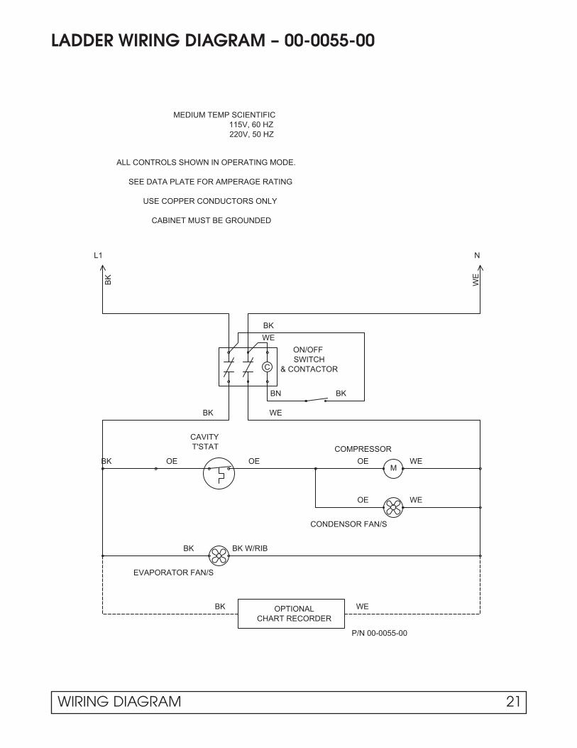
LADDER WIRING DIAGRAM – 00-0055-00
SWITCHON/OFF
L1 N
BK
WE
T'STAT
MEDIUM TEMP SCIENTIFIC115V, 60 HZ
CONDENSOR FAN/S
COMPRESSOR
M
C & CONTACTOR
220V, 50 HZ
WEOE
OE WE
OE
BK W/RIB
EVAPORATOR FAN/S
BK
OPTIONALCHART RECORDER
WEBK
BK
WE
BN
BK WE
ALL CONTROLS SHOWN IN OPERATING MODE.
CAVITY
BK
SEE DATA PLATE FOR AMPERAGE RATING
USE COPPER CONDUCTORS ONLY
CABINET MUST BE GROUNDED
BK
OE
P/N 00-0055-00
WIRING DIAGRAM 21

COMPRESSOR WIRING DIAGRAM – 00-0071-00
1
1
2
2
3
3
4
4
5
5
6
6
23 4
1
ST
AR
T C
AP
AM
ER
ICO
LD C
OM
PR
ES
SO
R A
SS
YS
C
O.L
.
R
HA
RN
ES
S-
CO
MP
RE
SS
OR
GR
-01
HA
RN
ES
S-
ST
AR
T
CO
MP
RE
SS
OR
RE
LAY
FA
N #
1
FA
N #
2(O
PT
ION
AL)
TE
RM
I NA
L B
OA
RD
CO
ND
EN
SO
R
F
CO
ND
EN
SO
R
(OP
TIO
NA
L)P
RE
SS
UR
E S
WIT
CH
5 A
MP
-125
/250
V
TE
RM
INA
L B
LOC
K
BK
RD
BE
PE
BN
OE
WE
YW
BE
RD
WE
OE
220V
, 50
HZ
115V
, 60
HZ
BE R
D
WEPIN
PIN
OE
ELE
CT
RIC
AL
BO
X A
SS
Y
CO
ND
EN
SO
R F
AN
AS
SY
CO
ND
EN
SO
R
NO
TE
S-
2)
F F
OR
WA
RD
RO
TA
TIO
N C
ON
DE
NS
OR
FA
N
(NO
RM
AL
OP
ER
AT
ION
)
1) S
TA
ND
AR
D C
ON
NE
CT
ION
S S
HO
WN
WIT
H S
OLI
D L
INE
S;
OP
TIO
NA
L C
ON
NE
CT
ION
S S
HO
WN
WIT
H D
AS
HE
D L
INE
S.
F
F
BK
OR
WE
BK
OR
WE
BK
BK
RU
N C
AP
FA
N L
EA
DS
BK
BK
F
OE
WE
WE
ST
AR
T B
OX
AS
SY
BK
OE
GR
-01
JUM
PE
R (
RE
MO
VE
WH
EN
INS
TA
LLIN
G P
RE
SS
UR
E S
WIT
CH
)
BK
BK
BK
22 WIRING DIAGRAM

COMPRESSOR WIRING DIAGRAM – 00-0084-00
1
1
2
2
3
3
4
4
5
5
6
6
ST
AR
T C
AP
CO
PE
LAN
D A
ST
54
S
C
O.L
.
R
HA
RN
ES
S-
CO
MP
RE
SS
OR
GR
-05
HA
RN
ES
S-
ST
AR
T
CO
MP
RE
SS
OR
FA
N #
1
FA
N #
2(O
PT
ION
AL)
TE
RM
INA
L B
OA
RD
CO
ND
EN
SO
R
F
CO
ND
EN
SO
R
(OP
TIO
NA
L)P
RE
SS
UR
E S
WIT
CH
5 A
MP
-125
/250
V
TE
RM
INA
L B
LOC
K
BK
RD
BE
PE
BN
OE
WE
YW
OE
220V
, 50
HZ
115V
, 60
HZ
BE
WE
OE
ELE
CT
RIC
AL
BO
X A
SS
Y
CO
ND
EN
SO
R F
AN
AS
SY
CO
ND
EN
SO
R NO
TE
S-
2)
F F
OR
WA
RD
RO
TA
TIO
N C
ON
DE
NS
OR
FA
N
(NO
RM
AL
OP
ER
AT
ION
)
1) S
TA
ND
AR
D C
ON
NE
CT
ION
S S
HO
WN
WIT
H S
OLI
D L
INE
S;
OP
TIO
NA
L C
ON
NE
CT
ION
S S
HO
WN
WIT
H D
AS
HE
D L
INE
S.
F
F
BK
OR
WE
BK
OR
WE
BK
BK
5
1
Z
RE
LAY
FA
N L
EA
DS
F
OE
WE
WE
ST
AR
T B
OX
AS
SY
OE
GR
-02
JUM
PE
R (
RE
MO
VE
WH
EN
INS
TA
LLIN
G P
RE
SS
UR
E S
WIT
CH
)
CO
MP
RE
SS
OR
AS
SY
115V
, 60
HZ
220V
, 50
HZ
OE
WE
BE
RD
BN
YW
RU
N C
AP
BE
WE
WE
IDE
NT
IFIE
DT
ER
MIN AL
BN
WE
WIRING DIAGRAM 23

COMPRESSOR WIRING DIAGRAM – 00-0137-00
1
1
2
2
3
3
4
4
5
5
6
6
ST
AR
T C
AP
CO
MP
RE
SS
OR
AS
SY
S
C
O.L
.
R
HA
RN
ES
S-
CO
MP
RE
SS
OR
GR
-01
HA
RN
ES
S-
ST
AR
T
CO
MP
RE
SS
OR
FA
N #
1
FA
N #
2(O
PT
ION
AL)
TE
RM
INA
L B
OA
RD
CO
ND
EN
SO
R
F
CO
ND
EN
SO
R
(OP
TIO
NA
L)P
RE
SS
UR
E S
WIT
CH
5 A
MP
-125
/250
V
TE
RM
INA
L B
LOC
K
BK
RD
BE
PE
BN
OE
WE
YW
BE
RD
WE
OE
220V
, 50
HZ
115V
, 60
HZ
OE
ELE
CT
RIC
AL
BO
X A
SS
Y
CO
ND
EN
SO
R F
AN
AS
SY
CO
ND
EN
SO
R
NO
TE
S-
2)
F F
OR
WA
RD
RO
TA
TIO
N C
ON
DE
NS
OR
FA
N
(NO
RM
AL
OP
ER
AT
ION
)
1) S
TA
ND
AR
D C
ON
NE
CT
ION
S S
HO
WN
WIT
H S
OLI
D L
INE
S;
OP
TIO
NA
L C
ON
NE
CT
ION
S S
HO
WN
WIT
H D
AS
HE
D L
INE
S.
F
F
BK
OR
WE
BK
OR
WE
BK
BK
FA
N L
EA
DS
F
OE
WE
WE
ST
AR
T B
OX
AS
SY
BK
OE
GR
-01
JUM
PE
R (
RE
MO
VE
WH
EN
INS
TA
LLIN
G P
RE
SS
UR
E S
WIT
CH
)
BK
WE
2M
RELAY
BE
1SCO
PE
LAN
D A
SE
24
115V
, 60
HZ
220V
, 50
HZ
RD
WE
24 WIRING DIAGRAM

ELECTRICAL BOX WIRING DIAGRAM – 00-0056-00
WIRING DIAGRAM 25

ELECTRICAL BOX WIRING DIAGRAM – 00-0057-00
26 WIRING DIAGRAM

ELECTRICAL BOX WIRING DIAGRAM – 00-0064-00
WIRING DIAGRAM 27

RACEWAY WIRING DIAGRAM – 00-0061-*
L
INC
AN
DE
SC
EN
T L
IGH
T
DO
OR
1
DO
OR
RE
CE
PT
AC
LE(O
PT
ION
AL)
PE
RIM
ET
ER
HE
AT
ER
(OP
TIO
NA
L)
WE
GN
GLA
SS
HE
AT
WE
WET
ER
MIN
AL
BLO
CK
(OP
TIO
NA
L)
X3
4
12
N
TIM
E C
LOC
K
OE
BK
YW
RD
TE
RM
INA
L B
LOC
K
RA
CE
WA
YTE
RMIN
AL B
LOCK
RD
5 A
MP
-125
/250
V
BE
BK
PE
BN
WE
YW
OE
RD
5 A
MP
-125
/250
VB
K
WE
BE
YW
PE
OE
BN
RD
5 A
MP
-125
/250
VB
K
WE
BE
YW
PE
OE
BN
ELE
CT
RIC
AL
BO
X A
SS
Y
OE
BLA
CK
TA
PE
LOW
TE
MP
MO
DE
LS
ME
D. T
EM
P &
INC
UB
AT
OR
MO
DE
LS
HA
RN
ES
S-
DO
OR
SW
ITC
H G
RO
UP
-01
ELE
CT
RIC
AL
BO
X A
SS
Y
PE
5 A
MP
-125
/250
V
N
TE
RM
INA
L B
LOC
K
TIM
E C
LOC
K
43
1
OE
2
HA
RN
ES
S-
DO
OR
SW
ITC
H G
RO
UP
-02
BLA
CK
TA
PE
OE
ME
D. T
EM
P M
OD
ELS
LOW
TE
MP
MO
DE
LS
YW
DO
OR
2
RD
YW
RD
BKB
E
WE
X
OE
BN
YW
TIM
E C
LOC
K
TE
RM
INA
L B
LOC
K
N
5 A
MP
-125
/250
V
PE
ELE
CT
RIC
AL
BO
X A
SS
Y
HA
RN
ES
S-
DO
OR
SW
ITC
H G
RO
UP
-03
BLA
CK
TA
PE
OE
LOW
TE
MP
MO
DE
LS
ME
D. T
EM
P M
OD
ELS
OE
12
34
YW
DO
OR
3
RD
RD
BKB
E
WE
X
BN
YW
OE
BK
DO
OR
1
RD
DO
OR
2
YW
RD
BK
DO
OR
1
RD
YW
1 D
OO
R
2 D
OO
R
3 D
OO
R
OP
TIO
NA
L D
OO
R S
WIT
CH
OP
TIO
NA
L D
OO
R S
WIT
CH
ES
OP
TIO
NA
L D
OO
R S
WIT
CH
ES
ELE
CT
RIC
AL
BO
X A
SS
Y
OP
TIO
NA
L IN
CA
ND
ES
CE
NT
INT
ER
IOR
LIG
HT
HA
RN
ES
S-
INC
AN
DE
SC
EN
T L
IGH
T
WE
RD
ELE
CT
RIC
AL
BO
X A
SS
Y
2 &
3 D
OO
R M
OD
ELS
MU
LLIO
N H
EA
TE
R
(OP
TIO
NA
L)
CA
BIN
ET
S O
NLY
)
SH
OR
T M
ULL
ION
HE
AT
ER
(QU
AD
-DO
OR
HA
RD
EN
ING
BN
BN
BN
RE
MO
VE
"O
E"
WIR
E O
N M
ED
. TE
MP
& IN
CU
BA
TO
R M
OD
ELS
RE
MO
VE
"O
E"
WIR
E O
N M
ED
. TE
MP
MO
DE
LS
RE
MO
VE
"O
E"
WIR
E O
N M
ED
. TE
MP
MO
DE
LS
WE
WE
BN
BN
BK
BK
BN
WE
WE
WE
C
NO
C
NO
NO
C
ALL
SO
LID
DO
OR
VE
RT
ICA
L M
OD
ELS
HA
RN
ES
S-
AN
TI-
SW
EA
T H
EA
TE
R
HA
RN
ES
S-
SH
OR
T M
ULL
ION
HE
AT
ER
OR
HA
RN
ES
S-
HA
RD
EN
ING
CA
BIN
ET
LIG
HT
21 3
3 12
McG
ILL
CA
RLI
NG
SW
ITC
H
DO
OR
SW
ITC
H T
ER
MIN
AL
NU
MB
ER
S
LOW
TE
MP
"P
ULS
E"
MO
DE
LS
LOW
TE
MP
"P
ULS
E"
MO
DE
LS
LOW
TE
MP
"P
ULS
E"
MO
DE
LSO
PT
ION
AL
AN
TI-
SW
EA
T H
TR
S
ALL
VE
RT
ICA
L M
OD
ELS
GN
BK
GN
RD
BN
WE
GN
BK
GN
RD
WE
BN
CU
TW
IRE
S
PU
LSE
MO
DE
LS
W/0
DIS
PLA
Y
OP
TIO
NA
L H
EA
TE
D D
OO
R
"PU
LSE
"
WE
BN
MO
DE
LSN
ON
-PU
LSE
W/D
ISP
LAY
PU
LSE
MO
DE
LSD
OO
RD
OO
R
31
2
AR
CO
ELE
CT
RIC
CN
ON
C(R
ED
)
PU
LSE
DIS
PLA
Y IN
SO
LID
DR
FR
T P
AN
EL
(OP
TIO
NA
L)
HA
RN
ES
S-
DIS
PLA
Y
TE
RM
INA
L B
LOC
K
YW
RD
BK
RD
WE B
E
OE
BN
PE
5 A
MP
-125
/250
V
YW
PERIMETER HEATER
DO
OR
SW
ITC
H
BK
BK
WE
WE
BN
ELE
CT
RIC
AL
BO
X A
SS
YU
ND
ER
CO
UN
TE
R M
OD
ELS
VE
RT
ICA
L M
OD
ELS
VE
RT
ICA
L M
OD
ELS
VE
RT
ICA
L M
OD
ELS
BLA
CK
TA
PE
RD+
-+
-B
KR
DB
K
HA
RN
ES
S-
DO
OR
SW
ITC
H
GR
OU
P-
04+
- BK
RD
BA
TT
ER
Y B
AC
KU
P
RE
CT
IFIE
R
PU
SH
BU
TT
ON
SW
ITC
H
BK
RD
0101
02
03 03
02
T T T
*GR
-01
*GR
-02
*GR
-03
*GR
-05
*GR
-04
13
24
21
3
DIS
PLA
Y
1 2
3 4
5 6
7 8
NO
34 65
12
12
3
3 2 1
*GR
-06
DIS
PLA
Y
14
23
12
3
1 2
3 4
5 6
7 8
O N
5 64
2 13
28 WIRING DIAGRAM

EVAPORATOR WIRING DIAGRAM – 00-0050-*
OEOEBN
WE
EV
AP
FA
N/S
RE
MO
TE
T' S
TAT
CA
VIT
Y
HA
RN
ES
S-
EV
AP
OR
ATO
R A
RE
AG
RO
UP
-02
EV
AP
OR
ATO
R A
RE
A
(RE
MO
VE
JU
MP
ER
WH
EN
INS
TALL
ING
TH
ER
MO
STA
T)
MO
UN
TED
CA
VIT
Y T
'STA
T1
FAN
2 FA
NS
WE
WE
BK
BK
BN
BN
BK
BK
WE
BN
OE
OE
OE
OE
US
E W
ITH
MO
UN
TED
HA
RN
ES
S-
EV
AP
OR
ATO
R F
AN
EX
TEN
SIO
NG
RO
UP
-01
; 1
DO
OR
GR
OU
P -
02;
2 D
OO
R/3
DO
OR
SP
AD
ES
PA
DE
14
32
76
59
8
OEYW
PEBNBERDGYWEBK
TO E
LEC
TRIC
AL
BO
X
HA
RN
ES
S-
MA
IN C
AB
INE
T(E
XIT
EV
AP
OR
ATO
R A
RE
A)
OE
12
34
56
78
9
BN
BK
BK
ME
D. T
EM
P M
OD
ELS
*GR
.-01
WIRING DIAGRAM 29

FLUORESCENT LIGHT WIRING DIAGRAM – 00-0067-*
HA
RN
ES
S-
LIGHT SWITCH
YW
YW BE
BE
RD
RD
BK
WE
WE
GY
RD
RD
BE
BE
YW
YW
BK
WE
RD
RO
CK
ER
OR
5 A
MP
-125
/250
V
BNOE
BE
PE
YW
(OPTIONAL)
GY
PU
SH
BU
TT
ON
LIG
HT
SW
ITC
H
BK
/WE
GY
LIG
HT
SW
ITC
H
WE
WE
YW
YW
YW
YWWE
WE
CAVITY SIDEWALL
BKGY BK BK/WE
CAVITY SIDEWALLLIGHT SWITCH
LIG
HT
SW
ITC
HP
US
HB
UT
TO
NR
OC
KE
R O
R
BK
/WE
GY
BK/WE
YW
YW
WE
WE
RD
RD
BE
BK
WE
RD
5 A
MP
-125
/250
V
YW PE
OE
BNW
E
BK
RD
WE
GY
RD
BE
BE
YW
YW
BE
BE
HA
RN
ES
S-
LIG
HT
SW
ITC
H
BK BKGY
(OPTIONAL)
YW
YW
WE
WE
BA
LLA
ST
RD
RD
RD
BK
WE
RD
GY
WE
YW
YW BE
BE
YW
YW BE
BE
BE
BE
WE
WE
BK
/WE
YW PE
5 A
MP
-125
/250
VB
K
WE
RD
BE
OE
BN
LIG
HT
SW
ITC
H
RO
CK
ER
OR
PU
SH
BU
TT
ON
GY
LIGHT SWITCH
BK/WE
CAVITY SIDEWALL
BK BKGY
YWWE
WE YW
WE
WE YW
(OPTIONAL)
WE
WE
WE
WE
RD
RD
BK
WE
YW
RD
RD
YW BE
BE
RD
BK
WE
GY
WE
GY
YW
YW
RD
RD
BE
BE
RD
GY
WE
YW
YW BE
BE
YW
YW BE
BE
HA
RN
ES
S-
LIG
HT
SW
ITC
H
RD
RD
BE
BE
WE YW
WE YW
WE
WE
FLO
UR
ES
CE
NT
LIG
HT
, GR
-03
HA
RN
ES
S-
RD
RD
YW
YW
WE
WEWE
WEBE
BE
GY
YWYW
YWYW
YWYW
YWYW
YWYW
YWYW
YWYW
YWYW
LAM
P F
IXT
UR
E E
XT
EN
SIO
NH
AR
NE
SS
-
YW YW
WE
WE
RD
RD
LAM
P F
IXT
UR
E E
XT
EN
SIO
NH
AR
NE
SS
-
FLO
UR
ES
CE
NT
LIG
HT
, GR
-02
HA
RN
ES
S-
YW
YW
WE
WE
YW
WE
WE
YW
YW
BE
YW
RD
RD
BE
BE
BE
YW
YW
YW YW
WE
WE
RD
RD
HA
RN
ES
S-
LAM
P F
IXT
UR
E E
XT
EN
SIO
N
HA
RN
ES
S-
FLO
UR
ES
CE
NT
LIG
HT
, GR
-01
YW
YW
WE
WE
YW
YW
YW
BE
BE
YW
BK
RD
BE
WE
5 A
MP
-125
/250
V
BN
PE
YW
OE
YW
WE
RD
GY
GY
BE
RD
YW BE
BK/WEBKBKGY
CAVITY SIDEWALL
(OPTIONAL)LIGHT SWITCH
WE
BK/WE
BK
BALLAST TRANS.HARNESS-
ON
E L
AM
P W
IRIN
G
TW
O L
AM
P W
IRIN
G
BA
LLA
ST
TW
O L
AM
P W
IRIN
G
BA
LLA
ST
TW
O L
AM
P W
IRIN
G
BA
LLA
ST
TW
O L
AM
P W
IRIN
G
BA
LLA
ST
(1)
DO
OR
CA
BIN
ET
- (
1- B
ALL
AS
T /
2- B
ULB
S)
*G
R-0
1
CA
VIT
Y L
IGH
T C
HA
NN
ELS
RA
CE
WA
Y
ELE
CT
RIC
AL
BO
X
CO
NT
RO
L P
AN
EL
OP
TIO
NA
L
CA
VIT
Y L
IGH
T C
HA
NN
ELS
OP
TIO
NA
L
(2)
DO
OR
CA
BIN
ET
- (
2- B
ALL
AS
T /
3- B
ULB
S)
*G
R-0
2
CO
NT
RO
L P
AN
EL
ELE
CT
RIC
AL
BO
X
RA
CE
WA
Y
(3)
DO
OR
CA
BIN
ET
- (
2- B
ALL
AS
T /
4- B
ULB
S)
*G
R-0
3
CO
NT
RO
L P
AN
EL
ELE
CT
RIC
AL
BO
X
OP
TIO
NA
LC
AV
ITY
LIG
HT
CH
AN
NE
LS
RA
CE
WA
Y
ELE
CT
RIC
AL
BO
X
CA
VIT
Y L
IGH
T C
HA
NN
ELS
RA
CE
WA
Y
EX
PO
RT
BA
LLA
ST
TR
AN
FO
RM
ER
INP
UT/
PR
IMA
RY
OU
TP
UT
/SE
CO
ND
AR
Y
SE
C
SEC
TY
PIC
AL
EX
PO
RT
TR
AN
SF
OR
ME
R C
ON
NE
CT
ION
S
*GR
-04
CA
P
CA
P
LAM
P 1
RD YW
L2L1
BE
C
LAM
P 2
RD BE
L2L1
YW
C
RD BE
CL1
YW
L2
LAM
P 1
RD YW
CL1
BE
L2
LINE
WH
T
BLK
LINE
WH
T
BLK
L2
BLK
WH
T
LINE
LAM
P 1
LAM
P 2
YW
YW
L1
BE
RD
CCL2B
E
L1RD
WH
T
LINE
BLK
LAM
P 1
LAM
P 2
RD BE
L2L1
YW
C C
RD YW
L1
BE
L2
WH
T
LINE
BLK
LAM
P 1
LAM
P 2
RD BE
L2L1
YW
C C
RD YW
L1
BE
L2
30 WIRING DIAGRAM

SOLENOID WIRING DIAGRAM – 00-0060-00
RD
5 A
MP
-125
/250
VB
K
BN
BE
WE
PE
OE
YW
WE
MO
DE
LSIN
ST
ALL
ON
RE
MO
TE
SO
LEN
OID
VA
LVE
LIQ
UID
LIN
E
BK
BK
OE
HA
RN
ES
S-
SO
LEN
OID
VA
LVE
WIRING DIAGRAM 31

RECEPTACLE BOX/LIGHT WIRING DIAGRAM – 00-0059-00
GN
BK
BK
CIR
CU
IT B
RE
AK
ER
TE
RM
INA
L B
LOC
K
GN
GN
TE
RM
INA
L B
LOC
K
RD
BE
BK
WE
5 A
MP
-125
/250
V
PE
BN
YW
OE
HA
RN
ES
S-
RE
CE
PT
AC
LE B
OX
SU
PP
LY
BK WE
WEBK
WE
WE
BK
BK
BK
BK
WE
WE
WE
BK
RE
CE
PT
AC
LE B
OX
- B
AC
K O
F C
AV
ITY
ELE
CT
RIC
AL
BO
X
32 WIRING DIAGRAM

RECEPTACLE BOX/LIGHT WIRING DIAGRAM – 00-0065-00
GN
5 AMP-125/250V
BE
WE
RD
BK
PE
YW OE
BN
HARNESS- LIGHT BOX SUPPLY
WE
WEGY BK BK
INCANDESCENT LIGHT
CIRCUIT BREAKER
TERMINAL BLOCK
1
2
3
4
5
6
7
8
9
C
L
GY GY
WE
BK
BK/WE
BN
GY
BK
PE
WE
DELUXE CONTROLPANEL CONNECTOR
BK/WE
ELECTRICAL BOX
LIGHT BOX- BACK OF CAVITY
WIRING DIAGRAM 33

CONTROL PANEL WIRING DIAGRAM – 00-0017-10
CIR
CU
IT B
OA
RD
TR
AN
SF
OR
ME
R
230V
NC
CO
M
NO
ALA
RM
115V
4-20
mA
(+)
GN
D(-
)
RT
D
GR
OU
ND
33
L
6V A
LAR
MR
ELA
Y33
TE
RM
INA
L S
TR
IP
6564
6261
C
LL
L
PO
WE
RF
AIL
UR
EIN
DIC
AT
OR
LOW
TE
MP
.
IND
ICA
TO
R
HIG
H
TE
MP
.IN
DIC
AT
OR
C+
-
TIM
E D
ELA
Y
RE
LAY
R E C P T A C L E
1 1 5 AV C
C H A R G E
1 2 V D C
AU
DIO
SIL
EN
CE
GR
OU
ND
41
37
20
12
18
9
9
13
13
28
28
36
36
23
16
17
12
19
3029
27
31
32
4
1
26
34
6 86059
21
14
24
25
7
7
1110
2
53
LOW
VO
LTA
GE
RA
CE
WA
Y
BA
TT
ER
Y
+-
INT
ER
IOR
LIG
HT
SW
ITC
H
1515
5119
52
68
67
66
53
35
63
54
47K
RE
SIS
TO
R
RE
SIS
TO
R15
15
PO
WE
RR
ELA
Y
SW
ITC
H
PO
WE
R
ON
/OF
F
+
-00
-C-0
017-
10R
M2-
26-9
6
HIG
H V
OLT
AG
ER
AC
EW
AY
RED
PINK
PU
SH
TO
TE
ST
DIG
IT D
ISP
LAY
MO
DU
LE #
1
69
3938
TO
MA
TIN
G P
LUG
ON
ELE
CT
RIC
AL
BO
X S
EE
DIA
GR
AM
MO
DU
LE #
2
ALA
RM
SY
ST
EM
SO
NA
LER
T
MO
DU
LE#3
DO
OR
AJA
R
CH
KD
DA
TE
AP
PR
DA
TE
RE
V
XX
XX
XX
XX
XX
X
WIR
EC
OD
ED
ET
AIL
GA
LTH
INC
LRW
IRE
TE
RM
INT
HK
(64)
WIR
ET
YP
E
DA
TE
DR
AW
N:
:
PA
RT
NO
.
RD
= R
ED
BK
= B
LAC
KB
E =
BLU
EB
N =
BR
OW
NW
E =
WH
ITE
OE
= O
RA
NG
E
GN
= G
RE
EN
PE
= P
UR
PLE
PK
= P
INK
GY
= G
RA
YT
N =
TA
N
CO
LOR
CO
DE
ITE
M N
OW
IRE
CO
DE Y
W=
YE
LLO
W
123456789101112131415161718192021222324252627282930313233343536373839404142434445464748495051525354555657585960616263646566676869
BLA
CK
& W
HIT
E L
EA
D18
RD
008G
R2A
18R
D05
4GQ
2AB
LAC
K L
EA
D18
PK
054G
Q2A
18P
K01
6GL2
A18
RD
020G
S2A
18G
Y01
6GL2
A18
YW
020Q
S2A
18P
E02
0RS
2A18
BE
020R
S2A
18R
D00
4GQ
2A18
YW
008Q
R2A
18B
N00
8GR
2A18
YW
008G
R2A
18Y
W00
8GQ
2A18
GY
004G
Q2A
18R
D00
4QQ
2AR
ES
IST
OR
W/L
EA
DS
18P
E00
8GQ
2A18
PE
008G
G2A
18P
E00
8DG
2A18
YW
004G
R2A
18G
Y00
8GG
2A18
GY
012D
G2A
18P
E00
8GR
2A18
OE
004G
R2A
18O
E00
8GG
2A18
WE
008G
Q2A
18B
K00
8GQ
2AB
LAC
K L
EA
DW
HIT
E L
EA
D18
BE
008G
Q2A
18B
K02
4GG
2A18
WE
024G
G2A
18B
N00
4GR
2A18
GY
032S
S2A
18B
K03
6GG
2A18
WE
036G
G2A
18O
E03
2SS
2A
18R
D00
8GS
2A
18O
E00
8GR
2A18
WE
004G
G2A
18B
K00
4GX
2A18
BN
008G
X2A
18B
N00
8GS
2A18
WE
008G
S2A
18P
E00
8GS
2A18
PK
008G
X2A
18G
Y00
8GX
2AW
HIT
E L
EA
DB
LAC
K L
EA
DB
RO
WN
LE
AD
OR
AN
GE
LE
AD
YE
LLO
W L
EA
DR
ED
LE
AD
PU
RP
LE L
EA
DB
LUE
LE
AD
GR
EE
N L
EA
D
19
L
40
18R
D00
8GR
2A
DO
OR
AJA
R
55
56
22
70
F
US
E 1
AM
P 1
9-A
-104
9-00
FUSE 1.0 AMP
70
D
TE
RM
. BO
AR
D
YW
WE
BN
OE
BK
WE
28
64
78
35
1
4
2
6
115V
4
3 2 1 7
6
5
8
RE
DR
ED
RE
D
NO
NC NO
NC
C C
RD
YW BN
GY PK
PE
3 4 1
2 8
INP
UT
E- +
WE
BK
OE TE
RM
. BO
AR
D
RD
BE
PE
OR
AN
GE
BU
TT
ON
NO
C
ON
PA
NE
LS W
/ALA
RM
MO
DU
LE O
PT
ION
.T
HE
SE
CO
NN
EC
TIO
NS
AR
E M
AD
E IN
TH
E R
AC
EW
AY
WE
BK
OE
BN
YW
RD
PE
BE
HA
RN
ES
S19
-102
0-00
BU
TT
ON
TE
RM
INA
LB
OA
RD
ALA
RM
TE
RM
INA
LB
OA
RD
(02)
(03)
(05)
(06)
(07)
(08)
(09)
(10)
(11)
(12)
(13)
(14)
(15)
(16)
(17)
(18)
(20)
(21)
(22)
(23)
(24)
(25)
(26)
(27)
(28)
(29)
(30)
(33)
(34)
(35)
(36)
(37)
(40)
(41)
(44)
(51)
(52)
(53)
(54)
(55)
(56)
(58)
(59)
(60)
19-0
998-
00
19-1004-00
RESISTOR47K
19-1009-00
5858
TE
RM
INA
L
ST
RIP
44
SE
NS
OR 44
*SH
IELD
ED
CA
BLE
19-
A-1
151-
00
* *
SH
IELD
ED
CA
BLE
AS
SE
MB
LYP
/N 1
9-A
-115
1-0
0
39
38
MO
DU
LE #
4
RE
CO
RD
ER
CH
AR
T7172
BLA
CK
19-
A-1
054-
05W
HIT
E 1
9-A
-105
4-04
71
7272
71
J5 4
J266
J3
CO
NT
RO
LLE
R/M
ON
ITO
R
J16
11
1
1
J43
1
34 WIRING DIAGRAM

CONTROL PANEL WIRING DIAGRAM – 00-0017-12
115V
230V
TR
AN
SF
OR
ME
R
CO
M
NC
NO
RT
D
GN
D(-
)
4-20
mA
(+)
CIR
CU
IT B
OA
RD
ALA
RM
GR
OU
ND
33
L
6V A
LAR
MR
ELA
Y33
TE
RM
INA
L S
TR
IP
6564
6261
C
LL
L
PO
WE
RF
AIL
UR
EIN
DIC
AT
OR
LOW
TE
MP
.IN
DIC
AT
OR
HIG
H
TE
MP
.IN
DIC
AT
OR
C+
-
TIM
E D
ELA
Y
RE
LAY
R E C P T A C L E
1 1 5 AV C
C H A R G E
1 2 V D C
AU
DIO
SIL
EN
CE
GR
OU
ND
48
37
20
12
18
9
9
13
13
28
28
36
36
23
16
17
12
19
3029
27
31
32
4
1
26
34
6 86059
21
14
24
25
7
7
1110
2
53
LOW
VO
LTA
GE
RA
CE
WA
Y
BA
TT
ER
Y
+-
INT
ER
IOR
LIG
HT
SW
ITC
H
1515
5119
52
68
67
66
53
35
63
54
47K
RE
SIS
TO
R
RE
SIS
TO
R15
15
PO
WE
RR
ELA
Y
SW
ITC
H
PO
WE
R
ON
/OF
F
+
-
00-C
-001
7-12
RM
2-26
-96
HIG
H V
OLT
AG
ER
AC
EW
AY
RED
PINK
PU
SH
TO
TE
ST
DIG
IT D
ISP
LAY
MO
DU
LE #
1
69
3938
TO
MA
TIN
G P
LUG
ON
ELE
CT
RIC
AL
BO
X S
EE
DIA
GR
AM
MO
DU
LE #
2
ALA
RM
SY
ST
EM
SO
NA
LER
T
CH
KD
DA
TE
AP
PR
DA
TE
RE
V
XX
XX
XX
XX
XX
X
WIR
EC
OD
ED
ET
AIL
GA
LTH
INC
LRW
IRE
TE
RM
INT
HK
(64)
WIR
ET
YP
E
DA
TE
DR
AW
N:
:
PA
RT
NO
.
RD
= R
ED
BK
= B
LAC
KB
E =
BLU
EB
N =
BR
OW
NW
E =
WH
ITE
OE
= O
RA
NG
E
GN
= G
RE
EN
PE
= P
UR
PLE
PK
= P
INK
GY
= G
RA
YT
N =
TA
N
CO
LOR
CO
DE
ITE
M N
OW
IRE
CO
DE Y
W=
YE
LLO
W
123456789101112131415161718192021222324252627282930313233343536373839404142434445464748495051525354555657585960616263646566676869
BLA
CK
& W
HIT
E L
EA
D18
RD
008G
R2A
18R
D05
4GQ
2AB
LAC
K L
EA
D18
PK
054G
Q2A
18P
K01
6GL2
A18
RD
020G
S2A
18G
Y01
6GL2
A18
YW
020Q
S2A
18P
E02
0RS
2A18
BE
020R
S2A
18R
D00
4GQ
2A18
YW
008Q
R2A
18B
N00
8GR
2A18
YW
008G
R2A
18Y
W00
8GQ
2A18
GY
004G
Q2A
18R
D00
4QQ
2AR
ES
IST
OR
W/L
EA
DS
18P
E00
8GQ
2A18
PE
008G
G2A
18P
E00
8DG
2A18
YW
004G
R2A
18G
Y00
8GG
2A18
GY
012D
G2A
18P
E00
8GR
2A18
OE
004G
R2A
18O
E00
8GG
2A18
WE
008G
Q2A
18B
K00
8GQ
2AB
LAC
K L
EA
DW
HIT
E L
EA
D18
BE
008G
Q2A
18B
K02
4GG
2A18
WE
024G
G2A
18B
N00
4GR
2A18
GY
032S
S2A
18B
K03
6GG
2A18
WE
036G
G2A
18R
D00
8GS
2A
18O
E00
8GR
2A18
WE
004G
G2A
18B
K00
4GX
2A18
BN
008G
X2A
18B
N00
8GS
2A18
WE
008G
S2A
18P
E00
8GS
2A18
PK
008G
X2A
18G
Y00
8GX
2AW
HIT
E L
EA
DB
LAC
K L
EA
DB
RO
WN
LE
AD
OR
AN
GE
LE
AD
YE
LLO
W L
EA
DR
ED
LE
AD
PU
RP
LE L
EA
DB
LUE
LE
AD
GR
EE
N L
EA
D
5556
22
70
F
US
E 1
AM
P 1
9-A
-104
9-00
FUSE 1.0 AMP
70
D
12
-+ 3
4
44
45
46
47
22
50
1312
1110
98
12
34
56
TE
MP
ER
AT
UR
EC
ON
TR
OLL
ER
SO
LID
ST
AT
ER
ELA
Y
DE
SC
RIP
TIO
NW
IRIN
G D
IAG
RA
M (
CO
NT
RO
L P
AN
EL)
18R
D00
8DG
2A18
PK
024S
S2A
18O
E02
4SS
2A18
YW
008A
D2A
18B
N00
8AD
2A18
BE
008A
G2A
7
RE
D WH
ITE
BLA
CK
19-1
020-
00H
AR
NE
SS
(44)
(45)
(46)
(47)
(48)
(49)
(50)
(51)
(52)
(53)
(54)
(55)
(56)
(58)
(59)
(60)
(37)
(36)
(35)
(34)
(33)
(30)
(29)
(28)
(27)
(26)
(25)
(24)
(23)
(22)
(21)
(20)
(18)
(17)
(16)
(15)
(14)
(13)
(12)
(11)
(10)
(09)
(08)
(07)
(06)
(05)
(03)
(02)
RD
BE
PE
BU
TT
ON
E- +
NO
C
WE
BK
OE
3 4 1
2 8
4 3 2 1 7
6
5
8
TE
RM
. BO
AR
D
8 5 6
7 3
1
4 2
ALA
RM
BU
TT
ON
NO
NC
NO
NC
C C
19-0
998-
00
TE
RM
INA
LB
OA
RD
RD
YW
BN
GY PK
PE
ON
PA
NE
LS W
/ALA
RM
MO
DU
LE O
PT
ION
.T
HE
SE
CO
NN
EC
TIO
NS
AR
E M
AD
E IN
TH
E R
AC
EW
AY
YW
WE
BN
OE
BK
WE
TE
RM
INA
LB
OA
RD
115V
2 6
8 4
WE
BK
OE
BN
YW
RD
PE
BE
19-1004-00
RE
DR
ED
RE
D
TE
RM
INA
LB
OA
RDP
OT
EN
TIO
ME
TE
R
5858
TE
RM
INA
L
ST
RIP
44
SE
NS
OR 44
CO
NT
RO
LLE
R/M
ON
ITO
R
*SH
IELD
ED
CA
BLE
19-
A-1
151-
00
* *
SH
IELD
ED
CA
BLE
AS
SE
MB
LY
P/N
19-
A-1
151-
00
DO
OR
AJA
R
MO
DU
LE#3
38
39
71
49
NO
TE
: WH
EN
CH
AR
T R
EC
OR
DE
R IS
NO
T
PR
ES
EN
T W
IRE
#48
IS C
ON
NE
CT
ED
T
O J
4/pi
n3 O
N C
ON
TR
OLL
ER
/MO
NIT
OR
A
ND
WIR
E #
37 IS
NO
T U
SE
D.
CH
AR
T R
EC
OR
DE
R
72B
LAC
K 1
9-A
-105
4-05
WH
ITE
19-
A-1
054-
04
71
72
71
72
J4
J3 J2 J1
J5 14
611
3
16 6
1
WIRING DIAGRAM 35

CONTROL PANEL WIRING DIAGRAM – 00-0058-*
L
WIT
HIN
DIC
AT
OR
LIG
HT
SW
ITC
H
47 K
5 A
MP
-125
/250
V
BE
WE
RD
BK
PE
YW
OE
BN
BA
LLA
ST
CO
NN
EC
TO
R/S
GY
GY
BK
/WE
WE
TE
RM
INA
L B
OA
RD
PU
SH
BU
TT
ON
CO
NT
RO
L P
AN
EL
ELE
CT
RIC
AL
BO
X
HA
RN
ES
S-
PA
NE
L, P
US
HB
UT
TO
N L
IGH
T
OP
TIO
N #
1- P
US
HB
UT
TO
N L
IGH
T S
WIT
CH
WIT
H IN
DIC
AT
OR
*
GR
-02
OP
TIO
N #
2- R
OC
KE
R L
IGH
T S
WIT
CH
*
GR
-04
HA
RN
ES
S-
PA
NE
L, R
OC
KE
R L
IGH
T
TE
RM
INA
L B
OA
RD
ELE
CT
RIC
AL
BO
X
BK
RD
PE
5 A
MP
-125
/250
V
BE
BN
WE
WE
YW
OE
GY
CO
NN
EC
TO
R/S
BA
LLA
ST
RO
CK
ER
LIG
HT
SW
ITC
H
CO
NT
RO
L P
AN
EL
BK
/WE
GY
12 5
4
OP
TIO
NA
L C
ON
TR
OL
PA
NE
L M
OU
NT
ED
LIG
HT
SW
ITC
H
KE
YE
D
CO
NT
RO
L P
AN
EL
87
2 64
3
CO
NT
AC
TO
R
ELE
CT
RIC
AL
BO
X
C
T1
L1 L2T
2
WE
GN
BK
BK
BN
HA
RN
ES
S-
PA
NE
L, K
EY
ED
ON
/OF
F
OP
TIO
NA
L C
ON
TR
OL
PA
NE
L M
OU
NT
ED
ON
/OF
F P
OW
ER
SW
ITC
H
OP
TIO
N #
1- K
EY
ED
ON
/OF
F S
WIT
CH
*
GR
-01
CO
NT
AC
TO
R
ELE
CT
RIC
AL
BO
X
T2
L2
T1
L1
C
OP
TIO
N #
2- R
OC
KE
R O
N/O
FF
SW
ITC
H
*GR
-03
CO
NT
RO
L P
AN
EL
BK
RO
CK
ER
BN
HA
RN
ES
S-
PA
NE
L, R
OC
KE
R O
N/O
FF
41
52
PO
WE
R C
OR
D
ON
/OF
F S
WIT
CH
ON
/OF
F S
WIT
CH
GY
BK
/WE
GY
BK
/WE
BN
WE
BK
BK
WE
WE
C
SE
RV
ICE
PLU
G
C
BN
WE
BK
BK
WE
WE
PO
WE
R C
OR
D
SE
RV
ICE
PLU
G
WE
GN
BK
DIA
GR
AM
FO
R 2
30/6
0S
EE
ELE
CT
RIC
AL
BO
XT
YP
FO
R 1
15/6
0 O
R 2
20/5
0
DIA
GR
AM
FO
R 2
30/6
0S
EE
ELE
CT
RIC
AL
BO
XT
YP
FO
R 1
15/6
0 O
R 2
20/5
0
L L
GN
D L
EA
D
GN
D L
EA
D
36 WIRING DIAGRAM

SECTION III
Maintenance
and
Repair
The manufacturer requires compliance to all CGCreclamation laws by saervice companies engagingin system processing.

WARNINGTo avoid the possibility of an electrical shock, turnOFF the thermostat and unplug the power cord ofthe cabinet before cleaning or touching electricalconnections or parts.

MAINTENANCE & REPAIRPRE-SERVICE CHECK LIST
You may avoid the cost and inconvenience of an unnec-essary product call by first reviewing this check list of themost frequently encountered situations that are not theresult of defective workmanship or materials.
COMPRESSOR RUNS TOO MUCH1. A refrigerated cabinet automatically compensates for
product loading by running longer and more often.Before calling for service, check running time for atleast one hour the first thing in the morning (beforestore traffic starts).
2. Be sure the doors seal. A faulty gasket seal will causeincreased running time.
3. Check the room temperature. The warmer the room,the more the compressor will run.
4. Check the condenser to be sure the face is clean. Dirtand lint will raise pressures and increase runningtime. Use a brush or vacuum to clean the condenser.
5. Be sure condenser fan operates.
6. Check to see that evaporator fans are running.
7. If product is too hard (cold), try setting theTemperature Control (thermostat) warmer. This willresult in warmer cabinet temperature and reducedrunning time.
8. Check insufficient ventilation to condenser.
CABINET DOES NOT OPERATE1. Be sure cabinet is plugged in.
2. Check that breakers or fuses are good and all switch-es in the supply line are ON.
3. Be sure that cabinet Master Power Supply Switch isON.
4. If you are in an area with voltage problems, try shut-ting off all non-essential electrical equipment.
LIGHT IS OFF1. If the cabinet is operating, be sure the lamp is prop-
erly seated in sockets.
2. If cabinet is not running, check that Master PowerSupply Switch and Light Switch are ON, fuses areokay, no switch in the supply is OFF, and that the cab-inet is plugged in.
CUSTOMER COMPLAINT ON STOREDPRODUCT1. Check cleaning solutions used inside cabinet.
2. Check cleaning solutions, paint, or other contami-nants used in store maintenance.
3. Sometimes the ingredients used in some products orcontainers will contaminate other products.
4. Be sure to follow a weekly schedule for cleaning cab-inet interior.
SERVICEIn the event of a malfunction, damage to the cabinet,or if the cabinet requires service beyond the items inthe “Pre-Service Checklist,” contact your local servicecompany or the dealer from whom the cabinet waspurchased.
POWER FAILUREDo not open the cabinet doors unnecessarily if power iscut off due to electrical failure. The cabinet will start up ifthe power supply returns, but will require sufficient timeto reach maximum cold storage performance.
CABINET FAILURE1. If the cabinet has stopped operating, check that the
cabinet is securely plugged in and turned on. Contacta licensed electrician to locate and correct any powersupply problems.
2. Do not open the cabinet doors unnecessarily.
3. Provisions for other storage of the product may berequired to prevent spoilage.
If you call for service, describe your problem and give thefollowing information to the service representative:
Cabinet Model No. ____________________________
Part No. ____________________________________
Serial No. __________________________________
(These numbers are located on a silver serial numberrating plate in the upper left side of the cabinet interior.)
MAINTENANCE & REPAIR 39

TOOLS:To provide full service diagnostics and repairs on thesecabinets, the following tools are needed:
A Multimeter
An Electronic Leak Detector
An Electronic Micron Gauge
A Vacuum Pump capable of pulling to 50 microns
Four Hand Valves
A Compound Gauge Set
A cylinder of nitrogen with a regulator capable of 10 to400 pounds.
Standard refrigeration hand tools, e.g.: wrenches, tubecutter, swage and flare tools, wire strippers, wire crimp.ers, wire cutters, slot and phillips head screwdrivers.
PRODUCT HISTORYThe first rule in servicing a refrigeration system is todetermine if the problem is an electrical or mechanicalfailure.
First, try to obtain the product’s history of operationfrom the customer. This will help identify the source ofthe problem.
Good facts from the cabinet user can help identifywhether the problem is electrical, within the refrigera-tion system, or a “misapplication by the user”. Get thehistory of operation and failure by asking these ques-tions:
1) Were there any brown-outs or power outages thatthey are aware of?
2) Is the cabinet on a dedicated circuit?
3) Has any other equipment in this area had opera-tional problems?
4) When was the last time the cabinet’s operation wasconfirmed as working properly?
5) When was a problem noticed?
6) How long has the equipment run without this prob-lem? (Years? Weeks? Days? Hours?)
7) Was anything tried prior to your arrival?
The refrigeration system should only be entered if it isabsolutely necessary. It is critical that a clean, uncon-taminated system be maintained.
If a system is unable to reach the proper operatingtemperature, a test of the unit’s mechanical refrigera-tion components is required.
COMPRESSOR EFFICIENCY TESTTo test the compressor, place compound gauge on thecompressor’s suction port.
While the compressor is running, close off the suctionline so that only the port and valve are part of the com-pressor’s low side.
When the valve is closed and vacuum has started, timehow long it takes to pull the compressor’s low side to itslowest possible vacuum.
Compressors used on these cabinets should be capableof pulling at least 20 to 22 inches of vacuum in less than40 seconds.
Next, shut off the compressor and watch the gauge. Aone or two inch rise in pressure is acceptable, since asmall amount of freon may remain on the low side of thecompressor, after which the reading should stabilize.
If the pressure continues to rise, the discharge reeds inthe valve head have failed, allowing high pressure gas toreturn to the compressor.
If the compressor pulls less than 20 inches, the suctionreeds have failed.
If the compressor takes longer than 40 seconds to pullto its ultimate low vacuum, one or both cylinders are notfunctioning as they should. Any reading less than thesewill require replacement of the compressor.
ENTERING THE SYSTEMEntering the system should only be done as a lastresort. Extreme care must be used no matter what thereason for entering the system. Of course there aretimes when it cannot be avoided, such as component orcompressor replacement, or a leak within the system.
The system must also be entered any time you need toobtain the operating pressures. Again, use extreme cau-tion to avoid any possible contamination.
Cabinets that use hermetic compressors typically do nothave valve ports, so therefore process stubs for bothsuction and discharge sides of the system were added.
Line taps should only be used to obtain pressure read-ings, and not for the reprocessing of the system. Theopening of a line tap is too restrictive for the pressure ofvacuum procedures.
On a hermetic compressor system, once you havedetermined that reprocessing a system is required,recover refrigerant and remove the line taps.
40 MAINTENANCE & REPAIR

Install hand valves at the process stub ends. Handvalves will be less restrictive to flow because of a largeropening. They will also be easier to use during repairprocedures.
EVACUATION Once the system has been cleaned and componentshave been replaced, you are ready to initiate the finalservicing procedures necessary to achieve proper cabi-net operation. Drier should be replaced prior to systemprocessing.
Pull an evacuation to approximately 50 microns.
CHARGINGYou should use a charging cylinder to measure in thecorrect amount of refrigerant.The charging methods are:
1. Add the refrigerant to the system until you reach abalanced pressure. This will give you an approxi-mate static charge.
2. Weigh in the refrigerant using a scale calibrated inounces.
The cabinet’s operation is now ready to be tested. Afinal check of the refrigeration lines should be madebefore running the cabinet.
Be sure the refrigeration lines are not kinked or rub-bing against each other.
Also check that the door seals properly. An air leak willaffect proper operation, and the cabinet’s ability toreach its coldest temperature.
Run the cabinet at both 100% run, and a cycling tem-perature for at least 24 hours. If the temperature andpressures are correct, the system can be consideredrepaired.
Hermetic systems should now have their processstubs pinched off, hand valves removed and the endsbrazed shut.
MAINTENANCE & REPAIR 41

COMPRESSOR INSTALLATION & MAINTENANCETO CHANGE THE COMPRESSOR:1. Disconnect the power supply to the cabinet.
2. Disconnect the power supply leads at thecompressor.
3. Disconnect wires to relay and capacitors.
4. Remove relay and starting capacitor and install onnew compressor.
5. Remove defective compressor from condensingunit base.
6. Set new compressor in place.
7. Reconnect relay and capacitor wires.
8. Reconnect power supply lead.
9. Leak test, evacuate, and weigh in charge.
CHANGING DRIERIf flare connected, make sure flares and faces of fit-tings on new drier are clean and in good conditionbefore installing new drier.
If sweat connected, clean tubing close to originaldrier before cutting tubing in clean area. Check thatends of the replacement drier are clean, then makebrazed connection using as little heat as possible.
Cut tubing only with tube cutters, not hacksaws, toavoid metal filings from entering the system. Driersmust be replaced any time you enter the system,except when you are obtaining pressures.
SERVICE VALVESThe compressors on some cabinets have servicevalves for measuring suction and discharge pressures.Two types are used. The first type is connected direct-ly to the compressor body or shell and back seats toconnect gauges to the access port. The second is onthe end of a process tube and requires a gauge orcharging line with a depressing pin to open valve whenthe connection is made.
This type valve should be tightlycapped except when making the
gauge connection.
TO CHECK FOR OPEN WINDINGSUse a multimeter. Measure ohms between “C” and “R”and between “C” and “S.”
If windings are O.K., multimeter will show a resistancereading between terminals.
If there is no reading, the compressor winding orwindings are open and the compressor should bereplaced.
TO CHECK FOR GROUNDED COMPRESSORUse multimeter. Touch probe from each terminal to anunpainted surface of compressor body. If there is noground, there will be no change of the meter.
WARNING: Be Careful Not to TouchUninsulated Parts of the Meter Probes
A reading indicates a ground and the compressorshould be replaced.
If there is voltage at the compressor terminals and thecompressor tries, but does not run, check voltage atthe compressor terminals while attempting to start thecompressor. If the voltage at the compressor terminalsis below 90% of the nameplate voltage, it is possiblethe motor may not have developed sufficient torque tostart. Check to determine if:
A. Wire sizes are adequate.B. Electrical connections are tight.C. The circuit is not overloaded.D. The power supply is adequate.
A defective relay or capacitor may prevent the com-pressor starting.
TO CHECK OUT THE RELAY1. Disconnect the cabinet from the power supply.2. Remove the wires from the relay.3. Touch probes to the contact terminals. Meter
should show infinity if closed.4. Touch probes to the terminals of coil. The meter
should show a resistance reading.
If items 3 and 4 are O.K., the relay is good. If items 3and 4 are not as indicated, change the relay.
CAUTION:
42 MAINTENANCE & REPAIR

TO CHECK CAPACITORS1. Disconnect the cabinet from the power supply.
2. Make sure the capacitors are discharged beforetouching terminal. (Shunt across the terminal ofcapacitor with a heavy insulated wire.)
3. Remove the wires from the capacitors.
4. Any capacitor found to be bulging, leaking, or dam-aged should be replaced.
5. Use a multimeter to check the run and startcapacitors for shorts or open circuits.
With a good capacitor, the indicator should first moveto a reading and then gradually increase to infinity.
If there is no reading change, an open circuit is indi-cated.
If the multimeter remains on a low resistance reading,a short circuit is indicated.
On run capacitor, touch probes to metal case andeach terminal. If meter show any reading, a ground is indicated. All defective capacitors should bereplaced.
MAINTENANCE & REPAIR 43
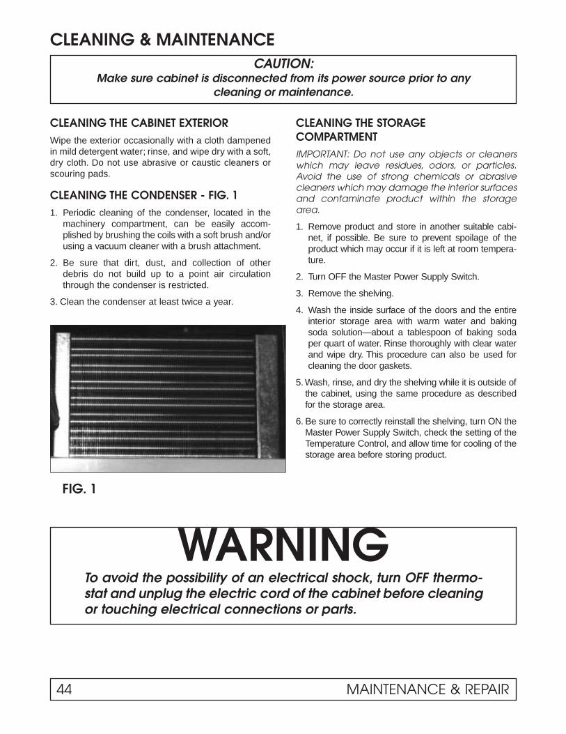
CLEANING & MAINTENANCE
CLEANING THE CABINET EXTERIORWipe the exterior occasionally with a cloth dampenedin mild detergent water; rinse, and wipe dry with a soft,dry cloth. Do not use abrasive or caustic cleaners orscouring pads.
CLEANING THE CONDENSER - FIG. 11. Periodic cleaning of the condenser, located in the
machinery compartment, can be easily accom-plished by brushing the coils with a soft brush and/orusing a vacuum cleaner with a brush attachment.
2. Be sure that dirt, dust, and collection of otherdebris do not build up to a point air circulationthrough the condenser is restricted.
3. Clean the condenser at least twice a year.
CLEANING THE STORAGECOMPARTMENTIMPORTANT: Do not use any objects or cleanerswhich may leave residues, odors, or particles.Avoid the use of strong chemicals or abrasivecleaners which may damage the interior surfacesand contaminate product within the storagearea.
1. Remove product and store in another suitable cabi-net, if possible. Be sure to prevent spoilage of theproduct which may occur if it is left at room tempera-ture.
2. Turn OFF the Master Power Supply Switch.
3. Remove the shelving.
4. Wash the inside surface of the doors and the entireinterior storage area with warm water and bakingsoda solution—about a tablespoon of baking sodaper quart of water. Rinse thoroughly with clear waterand wipe dry. This procedure can also be used forcleaning the door gaskets.
5. Wash, rinse, and dry the shelving while it is outside ofthe cabinet, using the same procedure as describedfor the storage area.
6. Be sure to correctly reinstall the shelving, turn ON theMaster Power Supply Switch, check the setting of theTemperature Control, and allow time for cooling of thestorage area before storing product.
WARNINGTo avoid the possibility of an electrical shock, turn OFF thermo-stat and unplug the electric cord of the cabinet before cleaningor touching electrical connections or parts.
CAUTION:Make sure cabinet is disconnected from its power source prior to any
cleaning or maintenance.
FIG. 1
44 MAINTENANCE & REPAIR

The ballast is located in the machinery compartment(A), attached to the back of the electrical control box(B).
1. Disconnect the power to the cabinet.
2. Remove the front panel.
3. Remove the cover panel on the electrical wiring box.
4. Disconnect the leads to the ballast.
5. Replace the ballast with correct part.
6. Replace the electrical wiring box cover panel.
7. Replace the front panel.
8. Reconnect the power to the cabinet.
BALLAST REPLACEMENT
Figure 1
Figure 2
MAINTENANCE & REPAIR 45

A nine pin wiring harness has been added to theupright models (med & low).
1. Electrical Box to cabinet
2. Main wiring harness to evaporator area.
ELECTRICAL BOX / QUICK CONNECT
1111
2222
46 MAINTENANCE & REPAIR

Disconnect the power supply to the cabinet.
Access the raceway (top or bottom mount) by remov-ing the front panels.
Remove the raceway cover.
1. Terminal board (power to mullion heater).
2. Heated door receptacle.
3. Door switch.
4. Fluorescent light harness.
CABINET RACEWAY / LOWER FRONT PANEL
1111
2222 3333
4444
MAINTENANCE & REPAIR 47

INSTRUCTIONS – SOLID DOOR REMOVAL, INSTALLATION& ADJUSTMENT
48 MAINTENANCE & REPAIR

CAM HINGE DOORS – OPERATION & REMOVAL(Solid Door Cabinets Only)
MAINTENANCE & REPAIR 49
HOLD-OPEN FEATURE
The doors can be opened up to a 95° angle and willmaintain that position for loading or unloading the stor-age compartment. Refer to Fig. 1.
Door Removal
The door can be removed by opening door 180°.Grasp door with one hand. Remove two screws locat-ed in top bracket of door opening. Door can be lifted upand away from the BTM Bracket pin.
NOTE: Door closer cartridge is spring loaded.
ALIGNING THE DOORS
Proper alignment of the cabinet doors will eliminatehinge binding and provide correct gasket seal.
Top Bracket door opening slotted holes for up anddown adjustment.
Spring Cartridge located in door, can be removed bytwo screws Top of Door.
BTM Bracket Door opening slotted holes are foradjustment Left or Right

TORSION ROD HINGED DOORS - Maintenance & RemovalGLASS DOOR CABINETS ONLYMAINTENANCE – ALIGNING DOORSProper alignment of the cabinet doors will eliminatehinge binding and provide correct gasket seal.
1. Check the level of the cabinet and door alignmentby firmly closing each door. Observe the movementof the other doors. They should open slightly, thenclose and seal.
2. The hinge wings fastened to the cabinet door haveslotted mounting holes for adjustment.
3. Additional adjustment can be made by addingshims between the hinge wing and either the dooror the cabinet face.
REMOVING DOORS:1. Loosen lower hex nut (Nut “A”) and release tension
on the torsion rod.
2. Remove the hitch pin from the upper hinge pin.
3. Hold the door steady and unscrew the pin at top ofthe door.The door can now be lifted out of the lowerhinge- bracket
REINSTALLING DOORS:1. Set lower square shaft on door in lower hinge
bracket
2. Insert top hinge pin and tighten to 12 ft./lbs. torque.
NOTE: Washer must be in place so top pin will notloosen and disconnect from door hinge.
3. Insert hitch pin through hole in upper hinge pin.
4. Run Nut “A” up snug. (You may have to loosen Nut“A” as you tighten tension as noted in Step 5.)
5. Set tension on door by turning square shaft in thedirection the door closes. Set tension so that thedoor will self close when opened approximately 1".(Do not overtighten so door will slam.) Tighten Nut“A” so tension can be maintained.
NUT "A"SQUARESHAFT
HINGE PIN
WASHER
HITCHPIN
TORQUE ROD REMOVAL1. Loosen nut “A” to remove door.
2. Attach vice grips to shaft.
3. Drive torque rod out of door.
4. Install new rod into keyway slot in door frame.
5. Reattach nut after installing door.
6. Turn shaft clockwise then lock nut “A”.
7. Add torque until door will close by itself.
50 MAINTENANCE & REPAIR
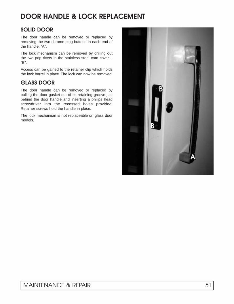
DOOR HANDLE & LOCK REPLACEMENT
SOLID DOORThe door handle can be removed or replaced byremoving the two chrome plug buttons in each end ofthe handle, “A”.
The lock mechanism can be removed by drilling outthe two pop rivets in the stainless steel cam cover –“B”.
Access can be gained to the retainer clip which holdsthe lock barrel in place. The lock can now be removed.
GLASS DOORThe door handle can be removed or replaced bypulling the door gasket out of its retaining groove justbehind the door handle and inserting a philips headscrewdriver into the recessed holes provided.Retainer screws hold the handle in place.
The lock mechanism is not replaceable on glass doormodels.
AAAA
BBBB
BBBB
MAINTENANCE & REPAIR 51

DOOR GASKET REPLACEMENT
The gasket is replaceable on glass or solid door models.A retainer is molded into the door frame. The door gas-ket is then tapped into the retainer and secured for air-tight door seal.
1. Remove door from cabinet.
2. Lay door front down on a flat, firm, nonscratch surface.
3. Pry up one corner of gasket with a putty knife orscrewdriver. Pull gasket from perimeter of doorretainer. Clean new gasket and straighten to insureproper fit.
4. Pull gasket from perimeter of door retainer.
5. Clean new gasket and straighten to insure properfit.
6. Place gasket over retainer in door frame.
7. Using a rubber mallet, tap the gasket into theretainer. (NOTE: Gasket can be soaked in warmwater to make pliable.)
8. Place door back onto cabinet.
52 MAINTENANCE & REPAIR

CENTER MULLION HEATER REPLACEMENT
DISCONNECT POWER SUPPLY TO CABINET
Grip inner mullion cover panel at top while pulling onthe inner mullion panel. Spread plastic extrusion apartat the top. Continue down the mullion assembly untilmullion cover is free. Set aside.
Again spread plastic extrusion apart and carefullyremove the insulation material. This will expose themullion heater taped in place. Heater leads are routedeither up or down (top mount or BTM mount) into anelectrical raceway to a terminal board where they canbe disconnected and replaced. Assemble in reverseorder.
Note: reseal holes provided with a silicone sealantupon repair.
MAINTENANCE & REPAIR 53

EVAPORATOR DRAIN PAN REPLACEMENTThe evaporator drain pan is located in the upper interiorof the cabinet. It pivots down for ease of accessibility.
1. Disconnect the power to the cabinet
2. Release R.H. and L.H. Lock screws.
3. Drop the front of the pan and swing it back.
4. Disconnect the ground wire.
5. Raise the pan, unhook from back.
6. Remove the drain line from the drain hole.
7. Remove the pan from the cabinet.
8. Reconnect the power to the cabinet.
54 MAINTENANCE & REPAIR

LIGHT SWITCH REPLACEMENTOn commercial models, the light switch is locatedinside the cabinet. It is on the light channel assembly.
On scientific cabinets, the light switch is located on thefront control panel.
1. Disconnect the power to the cabinet.
2. Remove the plastic lamp shield. Remove the lampbracket from the cabinet.
3. Remove the lock nut on the switch body.
4. Disconnect wire leads.
5. Connect new switch.
6. Replace the lock nut.
7. Replace the lamp shield.
8. Reconnect the power to the cabinet.
MAINTENANCE & REPAIR 55

FLUORESCENT BULB REPLACEMENT
1. Remove the plastic outer lamp shield.
2. Grasp the bulb.
3. Raise the bulb up. Pull out of the socket.
4. Remove the lamp shields and the end caps.
5. Place a new bulb in the shield. Attach the end caps.
6. Insert the bulb into the cabinet, push up and snapinto place.
56 MAINTENANCE & REPAIR

The thermostat is located in the upper left hand cornerof the drain pan area. It functions to control the tem-perature within the cavity of the cabinet. Rotate thethermostat clockwise for colder and counterclockwisefor warmer.
NOTE: location of bulb well in coil.1. Disconnect power to the cabinet.
2. Lower evaporator drain pan.
3. Remove screws on mounting bracket.
4. Slide thermal bulb assembly out of cabinet.
5. Replace thermostat into position as indicated inabove photo.
6. Replace screws.
7. Replace evaporator drain pan.
8. Reconnect power to cabinet.
(Do not crimp capillary tube. This will affect ther-mostat’s performance or make it inoperable.)
765
43
2 1
Colder
TEMPERATURE CONTROL
Position #7 is the coldest.Position #1 is the warmest.
Temperature Range Adjustment
MAINTENANCE & REPAIR 57

TEMPERATURE CONTROLFlammable Material Storage &Chromatography Refrigerators
SPECIFICATIONSFEATURES:Temp. Range: -30°F / -34°C
Adjustable Differential
Full Motor RatingCapillary Bulb Switch Elec. (Full Load)
Type Range °F Diff. °F Length Size Action Rating 120V AC 240V AC1609-101 -30 to +90 Adj. 31⁄2 to 40 5 ft. 53⁄4" x 3/8" Close FGH 16A 8A
(-34 to +32°C) (2 to 22°C) on Rise
58 MAINTENANCE & REPAIR

METERING DEVICE REPLACEMENTThe refrigerant metering device in this cabinet is
expansion valve. It is a Sporlan FBV 1/4-C. It is locat-ed on the face of the evaporator coil behind the drainpan. (Super heat setting 6° to 8° valve is fieldadjustable.)
1. Disconnect power to the cabinet.
2. Remove the evaporator drain pan.
3. Isolate the valve from the remainder of the system.
4. Remove the valve and replace with exact part num-ber new valve.
5. Reposition the sensing bulb in original location.
6. Replace the drain pan.
7. Reconnect power to the cabinet.
(Non-adjustable Shown)
MAINTENANCE & REPAIR 59

EVAPORATOR FAN MOTOR REPLACEMENT (Rear Fan)
1. Disconnect the power to the cabinet and locate theevaporator fan in the cabinet interior behind theevaporator coil.
2. Remove the fan guard by rotating it counter clock-wise to the position shown.
3. Remove the fan and bracket assembly by rotating itto the position shown.
4. Lower the fan assembly and remove the two screwsthat fasten the motor to the bracket.
Note: To assist the removal of the guard and bracket,press on the detent bumps to guide them out of theobround holes.
60 MAINTENANCE & REPAIR
SHELVING / DRAWERInstallation & Adjustment
To install shelves or drawers in a level position, insertthe cantilever plate tabs into the rectangular holes inthe desired position on the shelf standard. Lower therear of the shelf so that the slots in the plate are com-pletely down over the bottom of the holes.
NOTE: Supporting the front of the shelf with one handwhile pushing down on the rear of the shelf will helpease installation.
To slope shelves, insert the cantilever plate tabs intothe rectangular holes in the desired position on theshelf standard. Lift up on the rear of the shelf so thatthe top tab is locked behind the top of the rectangularhole. Hold the rear of the shelf up while lowering thefront of the shelf until the bottom tab is inserted in theappropriate hole in the shelf standard.
MAINTENANCE & REPAIR 61

CASTER INSTALLATION INSTRUCTIONS
62 MAINTENANCE & REPAIR

ELECTRICAL &REFRIGERATIONINFORMATION
BT30RF-FMSFlammable Material Storage
Refrigerator/FreezerTo meet the requirements for storing flammablematerial, cabinet has no openings, other than thedoor, or any electrical components below thecompressor compartment.
NOTE: Do not modify cabinet or remove label onthe front which specifies storage limits.
PERFORMANCE CHARACTERISTICS: TEMPERATURERefrigerator: 4°C (38°F)
Freezer: -15°C (5°F)

ELECTRICAL & REFRIGERATION SPECS. BT30RF-FMSMedium Temp., Solid, 1-Door Refrigerators
Compressor Model Number Americold HP110-1-3083
Compressor BTUH / -10°F Evaporator 1013
Recommended Operating Temp. Range (F/C) 35°F to 50°F (2°C to 10°C)
Cabinet Volts 115
Expansion Device Capillary .031 x 7"
Charge Refrig. Type / Oz. / Grams R404A / 13 / 368.5
SYSTEM COMPONENTS – R-404A
AMBIENT 70°F / 21.1°C 80°F / 27°C 90°F / 32.5°C
Cavity Temp. (F/C) 37 / 2.7 42 / 5.5 44 / 6.6
Suction Pressure (PSIG / Kpa) 4.8 / 33 8.1 / 56 11.9 / 82
Discharge Pressure (PSIG / Kpa) 180 / 1241 227 / 1565 262 / 1806
Compressor Amps 1.2 1.2 1.3
Total Refrigeration Amps 1.2 1.3 1.4
Freezer Temp. -3 / -19.5 -2 / -18.9 8 / -13
SYSTEM PERFORMANCE
ELECTRICAL / REFRIGERATION SPECIFICATIONS 65

EVAPORATOR LAYOUTThis cabinet is of standard design with the exceptionof a freezer compartment located at the top interior ofthe cabinet - “A”.
Depending on the application and number of dooropenings, this cabinet will need to be manuallydefrosted. A stainless steel pan has been provided tocollect the water during a manual defrost.
TO DECONTAMINATEShould more extensive cleaning and decontaminationbe necessary, the freezer door can be removed and theevaporator assembly pivoted down for complete accessto the cabinet interior. The seam of silicone rubbersealant may also be removed and replaced if needed.
TO REMOVE FREEZER DOOR1. Open freezer door and remove top thumbscrew
securing hinge support bracket to the cabinet wall.Tiltbracket forward and lift door off hinge pin.
2. Remove second fastener and hinge support bracket.
TO TILT FREEZER EVAPORATORASSEMBLY DOWN1. Pull tray and remove it from under freezer compart-
ment.2. Remove freezer door.3. Remove thumbscrews, lower left and right front side
of evaporator freezer interior.4. Carefully swing down front edge of evaporator freez-
er assembly for full access to back of freezer andupper interior cabinet walls. Thermostat bulb mayhave to be disconnected.
5. Reverse process to reassemble.
NOTE: Door may be hard to open for a short period after closing.Wait a few seconds to allow interior air pressure to balance.
DEFROSTING AND CLEANINGTo delay the need for a complete defrost, a plasticscraper may be used to scrape frost off of evaporatorfreezer surfaces.
However, a complete defrost will be required periodi-cally. To defrost, perform the following:
1. Unload product from cabinet.
2. Turn master power supply switch to “OFF,” andunplug power supply plug.
3. Collect defrost water in tray under evaporatorfreezer. A pan of warm water set in the freezer, ora fan blowing into it, will speed the process.
4. Wipe all freezer and drain tray surfaces clean.Let it dry.
5. Remove shelves and shelf standards if necessaryto wipe down and dry refrigerator compartment.
6. Return all components; plug in power supply cord;turn master supply switch to “ON.”
7. Once cabinet has attained desired temperaturereload cabinet with product.
AAAA
66 EVAPORATOR LAYOUT

THERMOSTAT BULB LOCATION & BT30RF-FMSSOLAR DIGITAL THERMOMETER OPT.These bulbs are located at the rear left hand side ofthe freezer box.
The thermostat is mounted to the electrical box on theright hand side. The temperature is set in degreesCelsius (Figure 1).
1111
THERMOSTAT BULB LOCATION & SOLAR DIGITAL THERMOMETER 67

CONDENSING UNIT AREA BT30RF-FMS
1. Compressor
2. Thermostat
3. Perimeter hot gas loop
4. Condenser coil
5. Strainer / Drier
6. Heat exchange
1111
5555
6666
Rear View
2222
3333
4444
68 CONDENSING UNIT AREA

ELECTRICAL &REFRIGERATIONINFORMATION
BT30RF-EXPRExplosion Proof
Refrigerator/Freezer

EXPLOSION PROOF REFRIGERATOR/FREEZER BT30RF-EXPR
The model 525D is also UL listed for storingFlammable Materials. DO NOT MODIFY CABINETOR REMOVE LABEL ON THE FRONT WHICH SPECIFIES STORAGE LIMITS.
CONTAINER REQUIREMENTSRefer to the latest edition of the following codes todetermine correct container requirements and the def-inition of flammable or combustible liquids.
National Fire Protection Agency (NFPA) 45 FireProtection for Laboratories using Chemicals.
National Fire Protection Agency (NFPA) 99 HealthCare Facilities Chapter 7, Laboratories in Health-Related Institutions.
NFPA Address: Batterymarch ParkQuincy, MA 02269
You must follow these codes when storing flammablematerials
The refrigerator/freezer complieswith the following:1. U.L. Listed, Commercial Refrigerator/Freezer for
Haz-ardous Locations. Also Listed for FlammableMaterials Storage. Control number 47R6.
2. For use in Class 1, Division 1, groups C and D Haz-ardous Locations. Operating Temperature Code, T4A.
3. Meets Requirements of OSHA 29CFR 1910.307.
4. Accepted for use: The City of New YorkDepartment of BuildingsMEA 327-87-E
CAUTION: TO PREVENT IGNITION OF HAZARDOUSATMOSPHERES, DISCONNECT THE PRODUCT FROMTHE SUPPLY CIRCUIT BEFORE OPENING ELECTRICALBOXES. KEEP ASSEMBLY TIGHTLY CLOSED WHEN INOPERATION.
For Satisfactory Operation 1. The cabinet should be free standing with a mini-
mum of 4" between the cabinet rear and the wall.To allow air flow over the compressor and machin-ery compartment, a minimum of 12" overheadclearance should be provided.
2. Level cabinet so door will slowly close when heldopen about 4" and released. This setting assuresself closing if the door is closed hard enough torebound open.
ELECTRICAL SUPPLY REQUIREMENTSThe electrical power supply must be installed accord-ing to the latest edition of the NATIONAL ELECTRI-CAL CODE – specifically Article 510 – Hazardous(Classified Locations - Specific). Appropriate materialsand wiring methods must be used in order to complywith the current National Electrical Code for Class 1,Group I and D area installation. All local and otherappropriate codes must be followed.
WARNING:Be absolutely sure that the surrounding location hasbeen checked for the absence of explosive concentra-tions before any electrical work is started.
Over current Protection: 15 amps. (If fuses are useduse time delay type.)
GROUNDING
WARNING:For personal safety, this cabinet must be properlyGROUNDED. The ground wire to the cabinet mustbe installed on the green screw located in the conduit outlet box. (Refer to drawing.)
The conduit outlet box is where the incoming powerwires are connected to the cabinet wires.
The incoming ground wire must be properly installedfrom the power supply. Consult a licensed electrician ifyou have any doubt about this wire being properlyinstalled.
EXPLOSION PROOF REFRIGERATOR/FREEZER 71

DEFROSTING & CLEANINGWhile scraping frost off of evaporator freezer surfaceswith a plastic scraper will delay the need, a completedefrost will be required periodically. To defrost:
1. Unload cabinet of product.
2. Disconnect or turn off the power supply.
3. Collect defrost water in tray under evaporator freez-er. Pans of warm water set in the freezer, or a fanblowing into it will speed the process.
4. Wipe all freezer and drain tray surfaces clean and dry.
5. Remove shelves and shelf standards if necessary,to wipe down and dry refrigerator compartment.
6. Return all components; connect power supply.
7. Once cabinet has attained desired temperature,reload cabinet with product. Intervals betweendefrosting will depend on product and number ofdoor openings, humidity, ambient temperature, etc.
To DecontaminateShould more extensive cleaning and decontaminationbe necessary, the freezer door can be removed and theevaporator assembly pivoted down for complete accessto the cabinet interior. The seam of silicone rubbersealant may also be removed and replaced if needed.
To Remove Freezer Door1. Open freezer door and remove top thumb screw
securing hinge support bracket to cabinet wall. Tiltbracket forward and lift door off hinge pin.
2. Remove second fastener and hinge support bracket.
To Tilt Freezer Evaporator Assembly Down1. Pull tray and remove it from under freezer com-
partment.
2. Remove freezer door.
3. Remove thumb screws, lower left and right frontside of evaporator freezer interior.
4. Carefully, swing down front edge of evaporatorfreezer assembly, for full access to back of freezerand upper interior cabinet walls. Thermostat bulbmay have to be disconnected.
5. Reverse process to reassemble.
72 EXPLOSION PROOF REFRIGERATOR/FREEZER

ELECTRICAL/REFRIGERATION SPECS. BT30RF-EXPRMedium Temp., Solid, 1-Door Refrigerator/Freezer
Compressor Tecumseh AE800AT-421-A4
Recommended Operating Temp. Range 35°F to 50°F (2°C to 10°C)
Cabinet Volts 115
Expansion Device Capillary Tube - 8' x .036
Charge Refrig. Type / Oz. / Grams R-134A / 10 / 283.5
SYSTEM COMPONENTS
AMBIENT 70°F / 21.1°C 80°F / 27°C 90°F / 32.5°CCavity Temp. (F/C) 37 / 2.7 41 / 5° 40 / 4.5
Suction Pressure (PSIG / Kpa) -3 / -21 3 / -21 1 / 7
Discharge Pressure (PSIG / Kpa) 107 / 738 126 / 869 144 / 993
Compressor Amps 2.1 2.2 2.4
Total Refrigeration Amps 2.4 2.4 2.4
Cabinet Pull Down 70° to 44° - Approx. 2 Hr.
SYSTEM PERFORMANCE
ELECTRICAL/REFRIGERATION SPECIFICATIONS 73
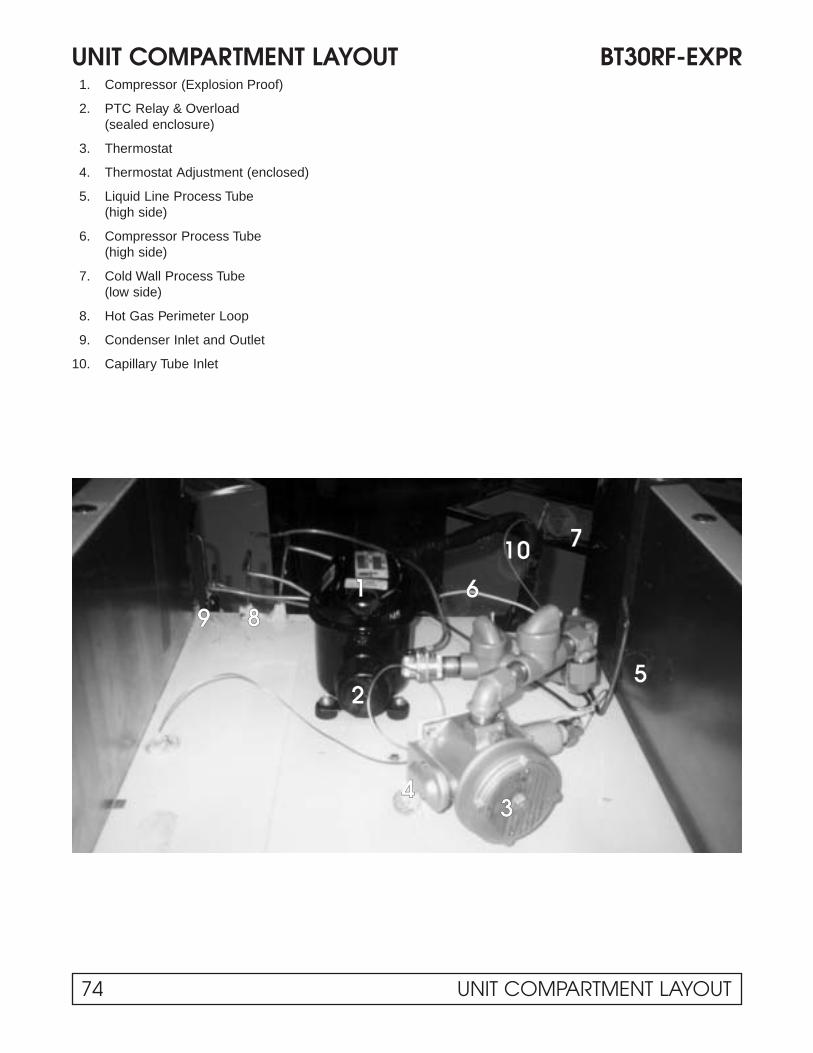
UNIT COMPARTMENT LAYOUT BT30RF-EXPR1. Compressor (Explosion Proof)
2. PTC Relay & Overload(sealed enclosure)
3. Thermostat
4. Thermostat Adjustment (enclosed)
5. Liquid Line Process Tube(high side)
6. Compressor Process Tube(high side)
7. Cold Wall Process Tube(low side)
8. Hot Gas Perimeter Loop
9. Condenser Inlet and Outlet
10. Capillary Tube Inlet
2255
44
118899
66
1100 77
33
74 UNIT COMPARTMENT LAYOUT
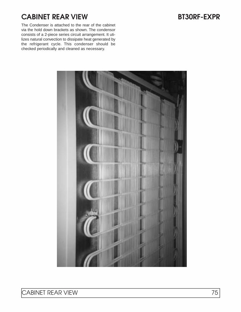
CABINET REAR VIEW BT30RF-EXPRThe Condenser is attached to the rear of the cabinetvia the hold down brackets as shown. The condensorconsists of a 2-piece series circuit arrangement. It uti-lizes natural convection to dissipate heat generated bythe refrigerant cycle. This condenser should bechecked periodically and cleaned as necessary.
CABINET REAR VIEW 75

TEMPERATURE CONTROL BT30RF-EXPRLocated on the unit compartment, behind the frontgrill. The temperature setting may be changed by:1. Remove the two screws that hold the cover in
place;2 Adjust the temperature control knob to desired cav-
ity temperature. Replace cover.
The thermostat dial is calibrated in degreesFahrenheit, but does not indicate temperatures insidethe storage compartment. Typical performance forthermostat control settings is listed below. Cabinetthermostats are factory preset for 0°F.
Thermostat Setting Freezer Temp. Cavity Temp.+20° +11°F 51°+10° +12°F 41°+5° +10°F 41°
SWITCH HOUSING COVER REMOVEDIMPORTANT: Use only factory authorized replace-ment parts and procedures.
CAUTION: Always disconnect supply circuitsbefore removing explosion proof cover.
REPLACEMENT OF SWITCHESTypes E121 & F1201. Remove cover, (2) switch mounting screws, switch
and insulator.
2. Disconnect (3) switch wires at switch terminal.
3. Install new switch and wire per SET POINTADJUSTMENTS.
4. Mount switch and insulator inside enclosure andrecalibrate per SET POINT ADJUSTMENTS.
SET POINT ADJUSTMENTSNOTE: For set point adjustments and recalibration,connect control to a calibrated temperaturesource and stabilize unit.
TYPE E121Adjust set point by turning external knob and pointer todesired setting on scale.
Recalibration—adjusting set point after replacingswitch(es) and/or thermal assembly:
Slowly turn adjustment knob until switch transfers.Compare switch transfer point to actual temperature. Ifthey do not agree, loosen set screws on adjustmentknob and align pointer to indicate actual temperature.
22
11
76 TEMPERATURE CONTROL

THERMOSTAT BULB PLACEMENT BT30RF-EXPRThe Thermostat Bulb is routed through a hole provid-ed on the top, lefthand side of the unit compartment(1). The bulb is then inserted into a clamp located on
top of the stainless steel evaporator as shown inFigure 2.
11
THERMOSTAT BULB PLACEMENT 77

EVAPORATOR LAYOUT BT30RF-EXPRThis cabinet is of standard design with the exceptionof a freezer compartment located at the top interior ofthe cabinet: “A”. Refrigeration is accomplished by tub-ing being attached to the freezer compartment hous-ing: “B”.
Depending on the application and number of dooropenings, this cabinet will need to be manuallydefrosted. A stainless steel pan has been provided tocollect the water during a manual defrost.
AAAA
BBBB
78 EVAPORATOR LAYOUT

USE COPPER CONDUCTORS ONLYCABINET MUST BE GROUNDED
The electrical power supply must be installed according to the latest edition of the National Electrical Code - Article510 - Hazardous (Classified) locations - specific appropriate materials and wiring methods must be used in orderto comply with the current code for Class I, Group C and D area installation. All local and other appropriate codesmust be followed. The installation must be made by a licensed professional electrician and contractor.
WIRING DIAGRAM 13-988-525D
THERMOSTATCOMPRESSOR
TERMINALBLOCK
OVERLOAD
WHITE
BLACK
VIOL
ET
115V / 60 HZ. / 1PHSUPPLY
WIRING DIAGRAM 79

ELECTRICAL &REFRIGERATIONINFORMATION
ST260RIST260RIR

MODULE #1 – DIGITAL DISPLAYBlood Bank & Incubator ModelsVendor – Analogic Effective Through June, 2002
GENERALThis module contains the ON/OFF power switch, inte-rior cabinet light switch and digital meter displayingcavity temperature.
1. Cabinet power is controlled by a keyed ON/OFFswitch. The key is removable in both positions. Inthe OFF position the battery charger and powerfailure relay in the optional Alarm System Moduleare still energized. CAUTION - Risk of ElectricalShock. Disconnect Power Before Servicing.
2. Interior cabinet light is controlled by a push button. Inthe recessed position, cabinet light is on and theswitch will glow (on glass door cabinet and incubatoronly).
3. The digital process meter monitors cavity conditions.Cabinet temperature is displayed on a green vacuumfluorescent display in degrees centigrade (°C). Fourred status indicators que the attendant of displaymode and temperature alarm conditions. The maxi-mum (peak) temperature and minimum (valley) tem-perature are saved for instant recall at a later time.The unit may be provided with alarm relay contactsfor audio, visual and remote signaling from theoptional Alarm System Module. Also a 420 mAprocess signal may be incorporated within the unit todrive an optional circular chart recorder.
SETTING & REVIEWING PARAMETERS1. In normal mode of operation the instrument displays
the current temperature reading. By pressing the ‘D’key, other values and operating parameters may besequentially reviewed. While the ‘D’ key is held downa code indicating the parameter is displayed; whenthe key is released, the parameter value is shown(See Table 1 for parameters). When these values aredisplayed, the two left side red indicator bars are lit,indicating a non-standard display (See Figure 1).
2. When the desired parameter value is displayed,press k key to enter numeric entry mode. One digitwill blink (for changing values only).
3. Press the m key to adjust this digit to the desiredvalue, then press k to select the next digit.
4. When the right most digit is blinking and correct,press the ‘E’ key to store the value and return to nor-mal meter operation.
5. If a mistake is made at any point before the ‘E’ key ispressed, press the ‘X’ key to cancel the operation andreturn to the default display.
6. The peak or valley values may be reset to the currentdisplay by pressing the ‘E’ key when the value is dis-played.
BUTTON FUNCTIONSD DISPLAY Display next parameters
in order
k RIGHT Make first Digit active.Then step right one digit.
m UP Increment active digit by one.
E ENTER Enter the displayed value inparameter memory or resetpeak or valley measurement.
X EXIT Cancel current operationand display interior cabinettemperature.
A NOT USED
9-Segment Display
Lit When NotShowing CavityTemperature in °C
Low Temp.Alarm Indicator
High Temp.Alarm Indicator
ButtonsLocatedBehind HingedAccess Cover
Cabinet Interior Light Switch(Glass Door Cabinets & Incubators)
Keyed ON/OFF
Power Switch
82 MODULE #1
FIGURE 1
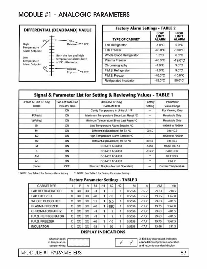
MODULE #1 – ANALOGIC PARAMETERS
MODULE #1 PARAMETERS 83

MODULE #1 – DIGITAL DISPLAYBlood Bank & Incubator ModelsVendor – Daytronics Effective July, 2002 Through Present
84 MODULE #1
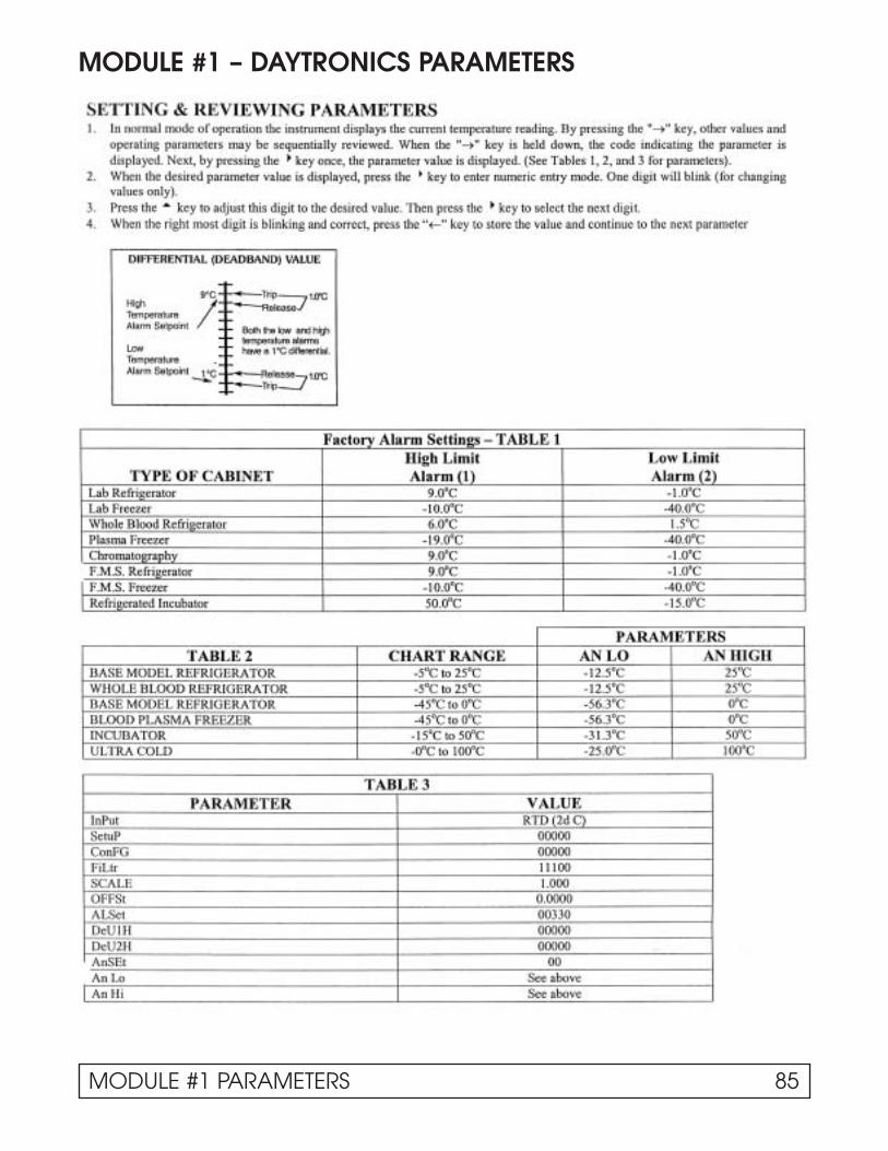
MODULE #1 – DAYTRONICS PARAMETERS
MODULE #1 PARAMETERS 85

OPTIONAL ALARM SYSTEM
GENERALThis module contains audio and visual alarm signals forpower failure, low and high cavity temperature, plus acontact for remote alarm connection.
1. A power failure alarm is provided to que the attendantof interrupted electrical service. This alarm is onlyfunctional when the keyed ON/OFF power switch is inthe ON position, and the battery is connected andproperly charged. In a power failure condition all cab-inet monitoring and operation ceases.
1. A. A rechargeable battery is provided external to thecommunicator panel, when the Alarm SystemModule is installed. Connect the red wire coded +to the positive battery terminal and the pink wirecoded - to the negative. The battery is located inthe compressor compartment.
1. B. Whenever the cabinet is plugged into an electricalsupply the power failure relay and battery chargerwill be energized regardless of the keyed ON/OFFpower switch position. This provides continuouscharging of the battery. Caution should be usedwhen servicing the cabinet.
1. B. CAUTION - Risk of Electrical Shock DisconnectPower Before Servicing Unit.
2. The temperature alarms indicate to the attendant thatcavity conditions are in excess of either the predeter-mined low or high temperature limits. These cavity
temperature limit alarms are signalled from the DigitalDisplay Module and set via the digital process meter.See Table 1 for factory settings.To adjust alarm pointssee “Setting and Reviewing Parameters” under MOD-ULE # 1, DIGITAL DISPLAY.
3. A button is provided for testing proper alarm systemsignaling. When depressed the battery is exclusivelyused to power all visual alarm indicators, audio alarmcircuit, and relay controlling the remote alarm contact.This test should be conducted daily to insure func-tionability and satisfactory battery charge. When test-ing alarms, visually check to see if lights from “PowerFailure,” “Low Temp.,” and “High Temp.” indicatorscome on when button is depressed. A burned outbulb in an indicator will disable that alarm function.
4. During an alarm situation, the audio portion of thealarm signal may be silenced by depressing the“SILENCE” button. If the alarm condition is not cor-rected within sixty minutes the audio signal will againbe activated. This function has no effect on the visualsignal or remote alarm contact.
5. A normally open alarm contact is provided on thereverse side of the communicator panel. It is intend-ed for low voltage, N.E.C. Class II wiring only. Uponan alarm condition the contact closes until the prob-lem, has been corrected.
FACTORY ALARM SETTINGSLOW HIGH
TYPE OF LIMIT LIMITCABINET ALARM ALARMLab Refrigerator ——— 9°CLab Freezer ——— -10.0°CWhole Blood Refrigerator 1.5°C 5.5°CPlasma Freezer -40.0°C -19°CRefrigerated Incubator -15.0°C 50.0°C
TABLE 1
Visual Alarm Indicators
Alarm CircuitTest Switch
Timed AudioSilence Switch
Audio Alarm
86 OPTIONAL ALARM SYSTEM

ALARM SYSTEMS COMPONENTS
Rear Views of an Alarm Module
1 Battery Charger
2 6 Volt Relay
3 120 Volt Relay
4 Silence Indicator Light
5 Time Delay Relay
6 Test Switch
7 High Temp. Indicator
8 Low Temp Indicator
9 Power Failure
10 Remote Alarm Contacts
1111
22223333
7777 99998888
44446666
5555
EmergencyProcedure Planning:Post adjacent to, or on the cabinetdoor, instructions to follow in theevent of an alarm condition:
1. Persons to be notified and thetelephone numbers of each;
2 The location of other refrigera-tor/freezers that might have thespace for emergency storage;
3. The telephone numbers tocall for electrical refrigerationsystem repair.
11110000
ALARM SYSTEMS COMPONENTS 87

GENERALIncubator cabinets incorporate a proportional electronictemperature controller.
Cavity temperature is maintainedby the electronic temperaturecontroller located on the commu-nicator panel. Set control knobpointer on desired cavity temper-ature. (See photo at left.)
Cavity temperature may fluctu-ate slightly with varying ambi-ent temperature.
The photo below shows the rear view of the tempera-ture control module. This module maintains cabinettemperature by pulsing voltage to a heater locatedunder the evaporator coil. This module consists of asolid state controller, solid state relay and a poten-tiometer. When replacing the solid state relay, makesure the polarity between the controller and the relaycoil are the same. When the cabinet has reached setpoint temperature, the load light indicator on the con-troller should be blinking on and off.
NOTE: If the cabinet temperature controller is setbelow 0°C manual defrost will be necessary.
CAVITY TEMPERATURE CONTROLRefrigerated Incubator
88 CAVITY TEMPERATURE CONTROL

MODULE #4 – DOOR AJAR/RECEPTACLE SWITCHESRefrigerators
WHOLE BLOOD REFRIGERATORS – GENERALThis type of refrigerator has a panel indicator to quethe attendant of an open cabinet door. The tempera-ture probe is located in a simulated product load with-in the cavity.
Whenever the cabinet door is open a panel indicatorlight is illuminated, when the door closes the light goesout.
DOOR AJAR
FIGURE 1
MODULE #4 89

WIRING DIAGRAM – Control Panel ST260RIRIncubator
115V
230V
TR
AN
SF
OR
ME
R
CO
M
NC
NO
RT
D
GN
D(-
)
4-20
mA
(+)
CIR
CU
IT B
OA
RD
ALA
RM
GR
OU
ND
33
L
6V A
LAR
MR
ELA
Y33
TE
RM
INA
L S
TR
IP
6564
6261
C
LL
L
PO
WE
RF
AIL
UR
EIN
DIC
AT
OR
LOW
TE
MP
.IN
DIC
AT
OR
HIG
H
TE
MP
.IN
DIC
AT
OR
C+
-
TIM
E D
ELA
Y
RE
LAY
R E C P T A C L E
1 1 5 AV C
C H A R G E
1 2 V D C
AU
DIO
SIL
EN
CE
GR
OU
ND
48
37
20
12
18
9
9
13
13
28
28
36
36
23
16
17
12
19
3029
27
31
32
4
1
26
34
6 86059
21
14
24
25
7
7
1110
2
53
LOW
VO
LTA
GE
RA
CE
WA
Y
BA
TT
ER
Y
+-
INT
ER
IOR
LIG
HT
SW
ITC
H
1515
5119
52
68
67
66
53
35
63
54
47K
RE
SIS
TO
R
RE
SIS
TO
R15
15
PO
WE
RR
ELA
Y
SW
ITC
H
PO
WE
R
ON
/OF
F+
-
00-C
-001
7-12
RM
2-26
-96
HIG
H V
OLT
AG
ER
AC
EW
AY
RED
PINK
PU
SH
TO
TE
ST
DIG
IT D
ISP
LAY
MO
DU
LE #
1
69
3938
TO
MA
TIN
G P
LUG
ON
ELE
CT
RIC
AL
BO
X S
EE
DIA
GR
AM
MO
DU
LE #
2
ALA
RM
SY
ST
EM
SO
NA
LER
T
CH
KD
DA
TE
AP
PR
DA
TE
RE
V
XX
XX
XX
XX
XX
X
WIR
EC
OD
ED
ET
AIL
GA
LTH
INC
LRW
IRE
TE
RM
INT
HK
(64)
WIR
ET
YP
E
DA
TE
DR
AW
N:
:
PA
RT
NO
.
RD
= R
ED
BK
= B
LAC
KB
E =
BLU
EB
N =
BR
OW
NW
E =
WH
ITE
OE
= O
RA
NG
E
GN
= G
RE
EN
PE
= P
UR
PLE
PK
= P
INK
GY
= G
RA
YT
N =
TA
N
CO
LOR
CO
DE
ITE
M N
OW
IRE
CO
DE Y
W=
YE
LLO
W
123456789101112131415161718192021222324252627282930313233343536373839404142434445464748495051525354555657585960616263646566676869
BLA
CK
& W
HIT
E L
EA
D18
RD
008G
R2A
18R
D05
4GQ
2AB
LAC
K L
EA
D18
PK
054G
Q2A
18P
K01
6GL2
A18
RD
020G
S2A
18G
Y01
6GL2
A18
YW
020Q
S2A
18P
E02
0RS
2A18
BE
020R
S2A
18R
D00
4GQ
2A18
YW
008Q
R2A
18B
N00
8GR
2A18
YW
008G
R2A
18Y
W00
8GQ
2A18
GY
004G
Q2A
18R
D00
4QQ
2AR
ES
IST
OR
W/L
EA
DS
18P
E00
8GQ
2A18
PE
008G
G2A
18P
E00
8DG
2A18
YW
004G
R2A
18G
Y00
8GG
2A18
GY
012D
G2A
18P
E00
8GR
2A18
OE
004G
R2A
18O
E00
8GG
2A18
WE
008G
Q2A
18B
K00
8GQ
2AB
LAC
K L
EA
DW
HIT
E L
EA
D18
BE
008G
Q2A
18B
K02
4GG
2A18
WE
024G
G2A
18B
N00
4GR
2A18
GY
032S
S2A
18B
K03
6GG
2A18
WE
036G
G2A
18R
D00
8GS
2A
18O
E00
8GR
2A18
WE
004G
G2A
18B
K00
4GX
2A18
BN
008G
X2A
18B
N00
8GS
2A18
WE
008G
S2A
18P
E00
8GS
2A18
PK
008G
X2A
18G
Y00
8GX
2AW
HIT
E L
EA
DB
LAC
K L
EA
DB
RO
WN
LE
AD
OR
AN
GE
LE
AD
YE
LLO
W L
EA
DR
ED
LE
AD
PU
RP
LE L
EA
DB
LUE
LE
AD
GR
EE
N L
EA
D
5556
22
70
F
US
E 1
AM
P 1
9-A
-104
9-00
FUSE 1.0 AMP
70
D
12
-+ 3
4
44
45
46
47
22
50
1312
1110
98
12
34
56
TE
MP
ER
AT
UR
EC
ON
TR
OLL
ER
SO
LID
ST
AT
ER
ELA
Y
DE
SC
RIP
TIO
NW
IRIN
G D
IAG
RA
M (
CO
NT
RO
L P
AN
EL)
18R
D00
8DG
2A18
PK
024S
S2A
18O
E02
4SS
2A18
YW
008A
D2A
18B
N00
8AD
2A18
BE
008A
G2A
7
RE
D WH
ITE
BLA
CK
19-1
020-
00H
AR
NE
SS
(44)
(45)
(46)
(47)
(48)
(49)
(50)
(51)
(52)
(53)
(54)
(55)
(56)
(58)
(59)
(60)
(37)
(36)
(35)
(34)
(33)
(30)
(29)
(28)
(27)
(26)
(25)
(24)
(23)
(22)
(21)
(20)
(18)
(17)
(16)
(15)
(14)
(13)
(12)
(11)
(10)
(09)
(08)
(07)
(06)
(05)
(03)
(02)
RD
BE
PE
BU
TT
ON
E- +
NO
C
WE
BK
OE
3 4 1
2 8
4 3 2 1 7
6
5
8
TE
RM
. BO
AR
D
8 5 6
7 3
1
4 2
ALA
RM
BU
TT
ON
NO
NC
NO
NC
C C
19-0
998-
00
TE
RM
INA
LB
OA
RD
RD
YW
BN
GY PK
PE
ON
PA
NE
LS W
/ALA
RM
MO
DU
LE O
PT
ION
.T
HE
SE
CO
NN
EC
TIO
NS
AR
E M
AD
E IN
TH
E R
AC
EW
AY
YW
WE
BN
OE
BK
WE
TE
RM
INA
LB
OA
RD
115V
2 6
8 4
WE
BK
OE
BN
YW
RD
PE
BE
19-1004-00
RE
DR
ED
RE
D
TE
RM
INA
LB
OA
RDP
OT
EN
TIO
ME
TE
R
5858
TE
RM
INA
L
ST
RIP
44
SE
NS
OR 44
CO
NT
RO
LLE
R/M
ON
ITO
R
*SH
IELD
ED
CA
BLE
19-
A-1
151-
00
* *
SH
IELD
ED
CA
BLE
AS
SE
MB
LY
P/N
19-
A-1
151-
00
DO
OR
AJA
R
MO
DU
LE#3
38
39
71
49
NO
TE
: WH
EN
CH
AR
T R
EC
OR
DE
R IS
NO
T
PR
ES
EN
T W
IRE
#48
IS C
ON
NE
CT
ED
T
O J
4/pi
n3 O
N C
ON
TR
OLL
ER
/MO
NIT
OR
A
ND
WIR
E #
37 IS
NO
T U
SE
D.
CH
AR
T R
EC
OR
DE
R
72B
LAC
K 1
9-A
-105
4-05
WH
ITE
19-
A-1
054-
04
71
72
71
72
J4
J3 J2 J1
J5 14
611
3
16 6
1
90 WIRING DIAGRAM

1 Evaporator Coil2 Cap Tube (14' x .042)3 Thermodisc
(open 140°F / close 130°F)
4 Heater Calrod(800 Watts / 16.5 Ohms)
5 R.T.D. Temperature Probe
INCUBATOR EVAPORATOR LAYOUT
CABINET INTERIOR LAYOUT
1 Receptacle Box2 2 Amp Fuse
3 Electrical Outlet4 Incandescent Light
11
33
55
3322
44
22
44
11
INCUBATOR EVAPORATOR & CABINET INTERIOR LAYOUTS 91

ELECTRICAL/REFRIGERATION SPECS. ST260RIRIncubator
Compressor HP117-1-3085
Compressor BTUH / -10°F Evap 1777
Recommended Operating Temp. Range 5°F to 122°F (-15°C to 50°C)
Cabinet Volts 115
Expansion Device Capillary .042 x 14'
Charge Refrig. Type / Oz. / Grams R404A / 15 / 425.2
SYSTEM COMPONENTS
AMBIENT 70°F / 21.1°C 80°F / 27°C 90°F / 32.5°CCavity Temp. (F / C) 31 / -2 30 / -2 30 / -2
Suction Pressure (PSIG / Kpa) 16 / 200 18 / 213 21 / 213
Discharge Pressure (PSIG / Kpa) 173 / 1068 198 / 1268 227 / 1358
Compressor Amps 2.4 2.6 2.8
Total Refrigeration Amps 10.8 6.1 10.1
SYSTEM PERFORMANCE
92 ELECTRICAL / REFRIGERATION SPECIFICATIONS

TROUBLESHOOTING CHARTS
TROUBLE COMMON CAUSE REMEDYUNIT WILL NOT RUN. Blown Fuse. Check power for “live” circuit. If outlet is
“dead” but building has power, replace thefuse. Try to determine the cause of the over-load or short circuit
Low Voltage. Check outlet with voltmeter. Should check115V plus or minus 10%.
If circuit is overloaded, either reduce load orhave electrician install separate circuit.
If unable to remedy any other way, installauto-transformer.
Open motor or temperature control. Jumper across terminals of control. If unitruns and connections are all tight, replacecontrol. Power element may have lostcharge or points may be dirty. Repair orreplace thermostat.
Open relay. Check relay. Replace if necessary.
Open overload. Check overload. Replace if necessary
Open compressor. Check compressor. Replace if necessary.
Open service cord. Check with ohmmeter at unit. If no circuitand current is indicated at outlet, replaceor repair.
Broken lead to compressors or cold Repair or replace broken leads.control.
Service cord not plugged in. Plug in cord.
CABINET TOO WARM. Thermostat position set too warm, not Turn knob to colder position.allowing unit to operate often enough.
Fan motor not running. Check and replace fan motor if necessary.
Shortage of refrigerant Check for leaks. Repair, evacuate andrecharge system.
Not enough air circulation around Relocate cabinet or provide clearance tocabinet. allow sufficient circulation.
Dirty condenser or obstructed Clean the condenser and the ducts.condenser ducts.
Thermostat control capillary not Refer back to removal/installationproperly installed. instructions detailed in this manual.
TROUBLESHOOTING 93

TROUBLE COMMON CAUSE REMEDYCABINET RUNS Not enough air circulation around Relocate cabinet or provide proper clearancesCONTINUOUSLY. cabinet or circulation is restricted. around cabinet. Remove restriction.
Cooling large quantities of product or Explain to customer that heavy loadingheavy loading. causes long running time.
Refrigerant charge undercharged Check, evacuate and recharge with properor overcharged. charge.
Room temperature too warm. Ventilate room as much as possible.
Thermostat defective. Check control. If it allows unit to operate allthe time, replace control.
NOISY OPERATION. Loose flooring or floor not firm. Tighten flooring or brace floor.
Tubing contacting cabinet or other tubing. Move tubing gently!
Cabinet not level. Level cabinet.
Compressor mechanically grounded. Replace compressor mounts.
Fan hitting drain pan or Move fan.mechanically grounding.
Shipping bands rubbing. Make sure all shipping bands have been cutand removed.
Loose fan blades or motor. Tighten fan blades and/or motor.
Loose parts or refrigeration or electrical Tighten all loose fittings. Move misplacedlines out of place. lines.
UNIT CYCLES ON Short relay. Replace relayOVERLOAD.
Weak overload protector. Replace overload protector.
Low voltage. Check outlet with voltmeter. Underload voltageshould be 115V plus or minus 10%. Checkfor several cabinets on same circuit orextremely long or underseed cord being used.
Short compressor. Check with meter and also ground beforereplacing.
CABINET LIGHTS Light switch off or defective. Try new bulb or bulbs. Inspect lampholdersWILL NOT WORK. for signs of bad connections.
COMPRESSOR Incorrect voltage. Check voltage to compressor terminalWILL NOT RUN. board. Voltage must be plus or minus 10% of
nameplate voltage.
94 TROUBLESHOOTING

TROUBLE COMMON CAUSE REMEDYUNIT RUNS Abnormally high, heavy use of cabinet. Heavy usage requires more operationTOO MUCH. Check usage and correct or explain.
Shortage of refrigerant. Unit must run Put in the normal charge and check forlonger and will operate at a lower leaks.than normal suction pressure.
Overcharge of refrigerant. Excess- Remove excess charge.ively cold or frosted suction liner results in lost refrigeration effort.
Restricted air flow over condenser Correct the condition.or air or non-condensable gasesin system.
High room temperature. Check for temperature variance. Correct condition.
Compressor inefficient. Replace.
Thermostat setting too cold. Raise setting.
UNIT SHORT CYCLES. Cycling on overload because of high/low Check voltage, head pressure and airline voltage with variance more or less passages. Repair and correct condition.than 10% from 115 volts. May alsobe caused by head pressures too high.
PRODUCT TOO COLD. Thermostat set too cold. Set warmer. (Setting #1 is the warmest; #7 isthe coldest.)
Thermostat bulb contact bad. If the bulb contact is bad, the bulb tempera-ture will lag behind the sleeve temperature,causing the unit to run longer and make thecabinet too cold. Make sure bulb makes goodcontact with the bulb well.
Room temperature abnormally low. Correct conditions.
PRODUCT TOO WARM. Thermostat set too warm. Set colder. (setting #1 is the warmest; #7the coldest.
Thermostat contact points dirty Clean or replace thermostat.or burned.
Thermostat out of adjustment. Readjust or change thermostat.
Excessive service load or abnormally Educate customer about problems that arehigh room temperature. caused by improper loading and excessive
room temperature fluctuations.
Excessive frost accumulation. Defrost the cabinet.
TROUBLESHOOTING 95

COMPRESSOR – TROUBLESHOOTING CHARTS
TROUBLE COMMON CAUSE REMEDYWON’T START. NO HUM. Open line circuit. Check wiring, fuses, receptacle.
Protector open. Wait for reset—check current.
Control contacts open. Check control, check pressures.
Open circuit in stator. Replace stator or compressor.
WON’T START. HUMS Improperly wired. Check wiring against diagram.INTERMITTENTLY.(cycling on protector) Low line voltage. Check main line voltage, determine location of
voltage drop.
Open starting capacitor. Replace starting capacitor.
Relay contacts not closing. Check by operating manually. Replace relay ifdefective.
Open circuit in start winding. Check stator leads. If leads are all right,replace compressor.
Stator winding grounded (normally Check stator leads. If leads are all rightwill blow fuse.) replace compressor.
High discharge pressure. Eliminate cause of excessive pressure. Makesure discharge shut-off and receiver valvesare open if applicable.
Tight compressor. Check oil level – correct binding condition, ifpossible. If not, replace compressor.
Weak starting capacitor or one weak Replace.capacitor of a set.
COMPRESSOR STARTS – Low line voltage. Bring up voltage.MOTOR WON’T GET OFFSTARTING WINDING. Improperly wired. Check wiring against diagram.
Defective relay. Check operation – replace relay if defective.
Running capacitor shorted. Check resistances. Replace capacitor if defective.
Starting and running windings shorted. Check capacitance – replace if defective.
Starting capacitor weak or one of a Check capacitance. Replace if defective.set open.
High discharge pressure. Check discharge shutoff valves.Check pressure.
Tight compressor. Check oil level. Check binding. Replace compressor if necessary.
96 TROUBLESHOOTING

TROUBLE COMMON CAUSE REMEDYCOMPRESSOR STARTS Low line voltage. Bring up voltage.& RUNS BUT CYCLESON PROTECTOR. Additional current passing through Check for added fan motors and pumps
protector. connected to wrong side of protector.
Suction pressure too high. Check compressor for proper application.
Discharge pressure too high. Check ventilation, restrictions and overcharge.
Protector weak. Check current - replace protector ifdefective.
Running capacitor defective. Check capacitance. Replace if defective.
Stator partially shorted or grounded. Check resistances; check for ground. Replaceif defective.
Inadequate motor cooling. Correct cooling system.
Compressor tight. Check oil level. Check for binding condition.
Unbalanced line (three-phase). Check voltage of each phase. If not equal,correct condition of unbalance.
Discharge valve leaking or broken. Replace valve plate.
STARTING CAPACITORS Short cycling. Reduce number of starts to 20 or less perBURNT OUT. hour.
Prolonged operation on starting Reduce starting load (install crankcasewinding. pressure limit valve), increase voltage if
low – replace relay if defective.
Relay contacts sticking. Clean contacts or replace relay.
Improper relay or incorrect relay setting. Replace relay.
Improper capacitor. Check parts list for proper capacitor rating:mfd. and voltage.
Capacitor terminals shorted by water. Install capacitors so terminals won’t be wet.
RUNNING CAPACITORS Excessive line voltage. Reduce line voltage to not over 10% aboveBURNT OUT. rating of motor.
High line voltage and light load. Reduce voltage if over 10% excessive.
Capacitor voltage rating too low. Install capacitors with recommended voltagerating
Capacitor terminals shorted by water Install capacitors so terminals won’t be wet.
RELAYS BURNT OUT. Low line voltage. Increase voltage to not less than 10% abovemotor rating.
Excessive line voltage. Reduce voltage to not more than 10% abovemotor rating.
Incorrect running capacitor. Replace with correct capacitor.
Short cycling. Reduce number of starts per hour.
Relay vibrating. Mount relay rigidly.
Incorrect relay. Use relay recommended for specific motorcompressor.
TROUBLESHOOTING 97

FLUORESCENT LAMP – TROUBLESHOOTING CHARTS
TROUBLE COMMON CAUSE REMEDYNORMAL END OF LIFE. Normal failure. Active material on Replace lamp promptly.Lamp won’t operate. Flashes momen- cathodes exhausted.tarily and goes out or blinks on and off. Ends probably blackened.
SHORT LIFE. Wrong lamp type used. Replace with lamp type marked in owner’smanual.
Wrong type of starter. Replace with correct starter.
Ballast not supplying the specified Replace with correct ballast for rating forelectrical values. lamp size.
Wrong type of ballast used. Replace ballast with proper type.
Too low or too high voltage. Check primary voltage with rangespecified on ballast name plate.
Poor circuit contact (likely at lamp- Lampholders should be rigidly mountedholders). and lamp securely seated.
Ballast improperly or incompletely Study ballast label wiring diagram andconnected. check connections.
Too many lamp starts. Average life for most lamps is dependent onnumber of starts and hours of operation.
END BLACKENING. Normal end of life. Replace lamp promptly.Dense blackening at one end or both, extending 2"-3" from base. Mercury deposit – generally within Should evaporate as lamp is operated.
1" of lamp end.
Poor circuit contact likely at the Lampholders should be rigidly mountedlampholder. and lamp securely seated.
Ballast improperly or incompletely Study ballast wiring instructions and checkconnected. connections.
Wrong type lamp used. Replace with correct lamp type.
Wrong type of starter or defective Replace with proper starter.starter causing on/off blinking orprolonged flashing at each start.
Ballast installed not supplying the Replace with ballast of correct rating forspecified electrical values. lamp size.
Line voltage too low or too high. Check line voltage with range specified onballast plate.
Ballast improperly or incompletely Study ballast label wiring instructions andconnected. check connections.
The manufacturer uses standard fluorescent lamps in ail of its applications. Standard one- and two-lamp ballast circuits are used.
Replacement lamps should be purchased over the counter from a local electrical wholesaler.
The table below indicates general problems that may be encountered with fluorescent lighting applications, possi-ble causes, and corrective maintenance suggestions.
98 TROUBLESHOOTING

TROUBLE COMMON CAUSE REMEDYNO STARTING EFFORT Open lamp cathode circuit due to If open, circuit is shown by continuity test orOR SLOW STARTING. broken cathode, air leak, or by viewing end of bulb against a pinhole
open weld. of light. Replace lamp.
Wrong lamp type used. Replace with lamp type indicated in owner’smanual.
Starter at end of life. Replace starter.
Starter sluggish. Replace starter.
Ballast installed not supplying the Replace with correct ballast of correctspecified electrical values. rating for lamp size.
Temperature cold air contact to Correct installation of lamp protectionbulb. tubes, or shields to prevent cold air effects.
Circuit voltage. Check voltage and correct if possible.
DECREASED LIGHT Temperature operation, cold air Properly install jacketed lamps whereOUTPUT. Full illumination of affects lamp performance. applicable.bulbs requires correct assemblyof all components of lighting system. Circuit voltage. Check voltage and correct if possible.
Ballast improperly or incompletely Study ballast label wiring instructions andconnected. check connections.
Dust or dirt on lamp or fixture. Clean.
BLINKING ON/OFF: Normal failure. Active material on Replace lamp promptly.Accompanied by shimmering cathodes exhausted.effect during “lighted” period.
Possible lamp fault in some lampholders. Replace lamp. Investigate further ifsuccessive lamps blink or flicker during “lighted” period.
Wrong type of starter or defective starter. Replace with proper starter.
Ballast installed not supplying the Replace with correct ballast with correctspecified electrical circuit. rating for lamp size.
Circuit voltage. Check voltage and correct if possible.
Loose circuit contact. Lampholders should be rigidly mounted andlamp securely seated.
OVERHEATED BALLAST. Wrong lamp type used. Replace with correct lamp number located inowner’s manual.
Wrong ballast used. Wrong voltage Replace ballast.rating.
Circuit voltage. Check voltage and correct to designspecifications.
Ballast improperly or incompletely Study ballast label. Correct if installedconnected. wrong.
TROUBLESHOOTING 99

COMPRESSOR AREA MEDIUM TEMP.Component Identification
START COMPONENT ASS'Y,
CONDENSER COIL
FAN MOTOR
COMPRESSORDESCRIPTION
FILTER/DRIERFAN BLADE
2
6
3
54
ITEM1
6
4
3
25
1
100 COMPRESSOR AREA ILLUSTRATION

ELECTRICAL BOX ASSEMBLY – (All components shown where applicable)
2
OFF
1 3
5
4
6
L1
L2
T1
T2
WH
ITE
YE
LLO
WO
RA
NG
E
PU
RP
LE
5 A
MP
-125
/250
V
BR
OW
N
FU
SE
BLA
CK
BLU
ER
ED
WH
ITE
YE
LLO
WO
RA
NG
E
PU
RP
LE
5 A
MP
-125
/250
V
BR
OW
N
FU
SE
BLA
CK
BLU
ER
ED
LAB
EL
REFER TO THIS VIEW FORMODELS WITH TIME CLOCKDEFROST CONTROL
HARNESS, BALLAST
CAPACITOR, RUN 55 MFD/370 60
START CAPACITOR
TOGGLE SWITCH, POWER
TERMINAL BOARD
RELAY, POWER (SCIENTIFIC MODELS)
BALLAST BOXASSEMBLY
6
RECEPTACLE
7
12
11
10
8
9
POWER CORD
RUN CAPACITOR
BALLAST
FUSE
THIS LOCATION USEDONLY ON DUALBALLAST MODELS
SEQ
5
6
4
3
2
1
6
THERMOSTAT
DESCRIPTION
9
8
HARNESS PLUG FROMBALLAST, WIREDFOR ONE LAMP,MUST BE IN THISPOSITION
114
7
3
2
REFER TO THESE VIEWS FOR COLD WALLAND DUAL TEMPERATURE MODELS
SIDE VIEW
THERMOSTAT, CW MODELS
SIDE VIEW
2
5
110
12
BALLAST ASSY.SEE DETAIL
OFF
ON
OFF
ON
7
ELECTRICAL BOX ILLUSTRATION 101

START COMPONENT ASSEMBLY
6
5
4
4
ORANGE JUMPER WIRE
BLACK WIRE
ORANGE WIRE
31
2
RELAY, START
TERMINAL BLOCK
3
4
2 CAPACITOR, RUN
1
DESCRIPTIONITEM
CAPACITOR, START
2
HARNESS, COMPRESSOR
HARNESS, ELECTRICAL BOX6
5
1
102 START COMPONENT ILLUSTRATION
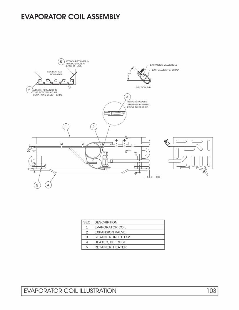
EVAPORATOR COIL ASSEMBLY
SECTION 'B-B'
45
REMOTE MODELS,STRAINER INSERTED
PRIOR TO BRAZING
5 4
3 STRAINER, INLET TXV
RETAINER, HEATER
HEATER, DEFROST4
5
DESCRIPTION
EXPANSION VALVE
EVAPORATOR COIL
SEQ
2
1
1 2
'A'
'B' 'A'
'B'
SECTION 'A-A'INCUBATOR
5 ATTACH RETAINER INTHIS POSITION AT ALLLOCATIONS EXCEPT ENDS
5
3
THIS POSITION ATATTACH RETAINER IN
ENDS OF COIL EXPANSION VALVE BULB
EXP. VALVE MTG. STRAP
1/16
EVAPORATOR COIL ILLUSTRATION 103

EVAPORATOR FAN SHROUD ASSEMBLY
104 EVAPORATOR FAN SHROUD ILLUSTRATION

SIDE LIGHT ASSEMBLY
1
3
2
2
1
3
SWITCH, TOGGLE
2 LAMPHOLDER, BOTTOM (STATIONARY)
3
1
DESCRIPTIONSEQ
LAMPHOLDER, TOP (SPRING LOADED PLUNGER)
ASSEMBLY SHOWN IS LEFT SIDE FOR TOP MOUNT MODELS. ON BOTTOM MOUNT MODELS WIRES EXIT AT THE BOTTOM AND THE SWITCH IS MOUNTED IN THE RIGHT SIDE ASSEMBLY.ON SCIENTIFIC MODELS, SWITCH IS MOUNTED IN THE CONTROL PANEL.
ASSEMBLY SHOWN IS RIGHT SIDE FOR BOTTOM MOUNT MODELS. ON TOP MOUNT MODELS WIRES EXIT AT THE TOP AND THE SWITCH IS MOUNTED IN THE LEFT SIDE ASSEMBLY. ON SCIENTIFIC MODELS, SWITCH IS MOUNTED IN THE CONTROL PANEL.
3
3
SIDE LIGHT ILLUSTRATION 105

MULLION LAMP ASSEMBLY
INSULATION
TAPE APPROX. EVERY12" AS SHOWN.
SUPPLY HARNESS
TOP LAMPHOLDER
DESCRIPTION
BOTTOM LAMPHOLDER
STANDARD MULLION
2 MIN3 MAX
1/2 MAX
ON OUTER PANEL
HEATER PLACEMENT
1/2 MAX
SEQ
6
5
4
HEATER
BREAKER
3
2
1
TAPE OVERHEATER,FULL LENGTH
LOCATE SPLICE APPROX. AS SHOWN. DO NOT BEND.TAPE MUST COVER SPLICE
1
COMPLETED ASS'Y
COMPLETED ASS'Y CROSS-SECTION
BOTTOM MOUNT WIRES
INNER PLATE W/LAMPTOP MOUNT SHOWN
EXIT AT BOTTOM
44
5/16 TYP
OUTER PLATE
INNER PLATE
3
3
6 2
106 MULLION LAMP ILLUSTRATION
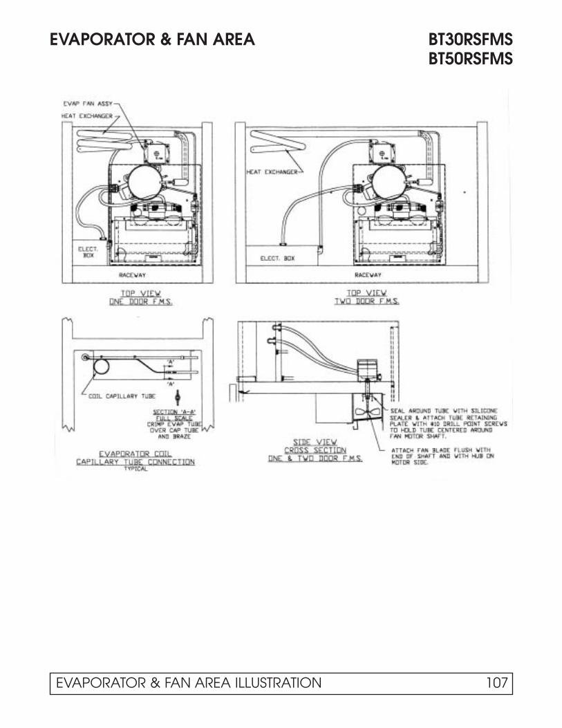
EVAPORATOR & FAN AREA BT30RSFMSBT50RSFMS
EVAPORATOR & FAN AREA ILLUSTRATION 107

SECTION IVPART LISTS
WHEN ORDERING PARTS FURNISH COMPLETE MODEL & SERIAL # INFORMATION.
Keep This Manual for Future Reference
Engineering and Technical Data are Subject to Change Without Notice.

PARTS LIST – One Door
T30MGP-4.1 UMG30BS-4.1 UMH30BS-4.1 BT30RG-4.1 BT30RGCH-4.1 ST30RGBB-4.1 T30MSP-4.1 BT30RS-4.1 BT30RSFMS-4.1
Compressor 16-0221-00 16-0221-00 16-0221-00 16-0221-00 16-0221-00 16-0221-00 16-0310-00 16-0310-00 16-0308-00Start Relay 17-0286-00 17-0286-00 17-0286-00Start Capacitor 17-0143-00 17-0143-00 17-0143-00 17-0143-00 17-0143-00 17-0143-00 17-0291-00 17-0291-00 17-0291-00Run Capacitor 17-0288-00 17-0288-00 17-0288-00Motor Protector, Compr 17-0316-00 17-0316-00 17-0314-00Condenser Coil 18-1211-01 18-1211-01 18-1211-01 18-1211-01 18-1211-01 18-1211-01 18-1211-01 18-1211-01 18-1211-01Fan Motor, Cond 19-0933-00 19-0933-00 19-0933-00 19-0933-00 19-0933-00 19-0933-00 19-0933-00 19-0933-00 19-0933-00Fan Blade, Cond 19-0101-00 19-0101-00 19-0101-00 19-0101-00 19-0101-00 19-0101-00 19-0101-00 19-0101-00 19-0101-00Filter/Drier 18-1106-00 18-1106-00 18-1106-00 18-1106-00 18-1106-00 18-1106-00 18-1106-00 18-1106-00 18-1106-00Heat Exchange 50-0219-01 50-3682-00 50-3682-00 50-0219-01 50-0219-01 50-0219-01 50-0222-01 50-0222-01 50-3783-02Evaporator Coil 18-0713-00 18-0713-00 18-0713-00 18-0713-00 18-0713-00 18-0713-00 18-0713-00 18-0713-00 18-0713-00Expansion Valve 18-0386-08 18-0386-08 18-0386-08 18-0386-08 18-0386-08 18-0386-08Capillary Tube 14-2403-00 14-2403-00 14-2408-00Harness, Evap 19-1652-02 19-1652-02 19-1652-02 19-1652-02 19-1652-02 19-1652-02 19-1652-02 19-1652-02Fan Motor, Evap 19-1221-00 19-1221-00 19-1221-00 19-1221-00 19-1221-00 19-1221-00 19-1221-00 19-1221-00 24-0500Fan Blade, Evap 19-1223-00 19-1223-00 19-1223-00 19-1223-00 19-1223-00 19-1223-00 19-1223-00 19-1223-00 19-1042-00Motor Mount, Evap 10-1478-00 10-1478-00 10-1478-00 10-1478-00 10-1478-00 10-1478-00 10-1478-00 10-1478-00Grill, Evap Fan 10-1479-00 10-1479-00 10-1479-00 10-1479-00 10-1479-00 10-1479-00 10-1479-00 10-1479-00 15-0291-00Switch, Power 19-0103-00 19-0103-00 19-0103-00 19-1006-00 19-1006-00 19-1006-00 19-0103-00 19-1006-00 19-1006-00Relay, Power 19-1005-00 19-1005-00 19-1005-00 19-1005-00 19-1005-00Thermostat, Cabinet 19-1030-02 19-1030-02 19-1030-02 19-1030-02 19-1030-02 19-1031-00 19-1030-02 19-1030-02 19-1031-00Power Cord 19-0620-00 19-0620-00 19-0620-00 19-0620-00 19-0967-00 19-0620-00 19-0620-00 19-0620-00 19-0620-00Harness, Ebox to Main 19-1675-02 19-1675-02 19-1675-02 19-1675-02 19-1675-02 19-1675-02 19-1675-02 19-1675-02Heater, Cond Pan 19-1688-00 19-1688-00 19-1688-00 19-1688-00 19-1688-00 19-1688-00Ballast 19-1725-00 19-1725-00 19-1725-00 19-1725-00 19-1725-00 19-1725-00Harness, Ballast 19-1730-00 19-1730-00 19-1730-00 19-1730-00 19-1730-00 19-1730-00Fuse, Lights 19-0970-00 19-0970-00 19-0970-00 19-0970-00 19-0970-00 19-0970-00Lampholder, Top 19-0957-01 19-0957-01 19-0957-01 19-0957-01 19-0957-01 19-0957-01 503-248DLampholder, Bottom 19-0957-02 19-0957-02 19-0957-02 19-0957-02 19-0957-02 19-0957-02Switch, Light 19-0729-00 19-0729-00 19-0729-00 19-1003-00 19-1003-00 19-1003-00Lamp 19-1040-00 19-1040-00 19-1040-00 19-1040-00 19-1040-00 19-1040-00 22-0213Safety Shield, Lamp 10-0983-00 10-0983-00 10-0983-00 10-0983-00 10-0983-00 10-0983-00Cover, Lamp 10-0809-00 10-0809-00 10-0809-00 10-0809-00 10-0809-00 10-0809-00 44-1034Breaker Trim, Side 10-1485-02 10-1485-02 10-1485-02 10-1485-02 10-1485-02 10-1485-02 10-1485-02 10-1485-02 10-1485-02Breaker Trim, Top/Btm 10-1485-03 10-1485-03 10-1485-03 10-1485-03 10-1485-03 10-1485-03 10-1485-03 10-1485-03 10-1485-03Thermometer, Solar 19-1050-03 19-1050-03 19-1974-00 19-1050-03 19-1050-03Switch, Door 19-0969-00 19-0969-00Hinge, Lower LH 03-1232-01 03-1232-01Hinge, Lower RH 03-1232-02 03-1232-02 03-1232-02 03-1232-02 25-0178-09 25-0178-09 25-0178-09Hinge, Upper LH 03-1231-03 03-1231-03Hinge, Upper RH 03-1231-04 03-1231-04 03-1231-04 03-1231-04 25-0178-03 25-0178-03 25-0178-03Hold Open Arm, RH 25-0543-02 25-0543-02 25-0543-02Door Assy, LH 51-0988-07 51-0988-19Door Assy, RH 51-1027-08 51-1027-16 51-1027-16 51-1027-20 51-0172-02 51-0172-02 51-0172-02Door Closer 50-3159-00 50-3159-00 50-3159-00 50-3159-00 50-3159-00 50-3159-00 25-0178-01 25-0178-01 25-0178-01Gasket, Door 10-0822-02 10-0822-02 10-0822-02 10-0822-02 10-0822-02 10-0822-02 10-0882-05 10-0882-05 10-0882-05Handle, Door 25-0518-00 25-0409-00 25-0409-00 25-5055-00 25-5055-00 25-5055-00 25-5055-00 25-5055-00 25-5055-00Lock, Door 25-0412-02 25-0412-02 25-0412-02 25-0226-00 25-0226-00 25-0226-00Shelf, Cantilever 15-0267-00 15-0267-00 15-0267-00 15-0325-00 15-0284-00 15-0267-00 15-0325-00 15-0325-00Shelf, Bottom 15-0197-03 15-0197-03 15-0197-03 15-0197-03 15-0197-03 15-0197-03 15-0197-03 15-0197-03Drawer Assembly 50-3145-03Pole Mast 15-0285-00Leg, Adjustable 33-0504-01 33-0504-01 33-0504-01 33-0504-01 33-0504-01 33-0504-01 33-0504-01Front/Control Panel Assy 50-0176-01 50-0176-01 50-0176-01 51-0174-01 51-0174-01 50-2999-46 50-0176-11 51-0174-04 51-0174-04
PARTS LIST - ONE DOOR MEDIUM TEMPERATURE
PARTS LIST 111

PARTS LIST – Two Door
T50MGP-4.1 UMG50BS-4.1 UMH50BS-4.1 BT50RG-4.1 BT50RGCH-4.1 ST50RGBB-4.1 T50MSP-4.1 BT50RS-4.1 BT50RSFMS-4.1
Compressor 16-0222-00 16-0222-00 16-0222-00 16-0222-00 16-0222-00 16-0222-00 16-0310-00 16-0310-00 16-0308-00Start Relay 17-0146-00 17-0146-00 17-0146-00 17-0146-00 17-0146-00 17-0146-00 17-0286-00 17-0286-00 17-0286-00Start Capacitor 17-0147-00 17-0147-00 17-0147-00 17-0147-00 17-0147-00 17-0147-00 17-0291-00 17-0291-00 17-0291-00Run Capacitor 17-0149-00 17-0149-00 17-0149-00 17-0149-00 17-0149-00 17-0149-00 17-0288-00 17-0288-00 17-0288-00Motor Protector, Compr 17-0316-00 17-0316-00 17-0314-00Condenser Coil 18-0546-02 18-0546-02 18-0546-02 18-0546-02 18-0546-02 18-0546-02 18-1211-01 18-1211-01 18-1211-01Fan Motor, Cond 19-0933-00 19-0933-00 19-0933-00 19-0933-00 19-0933-00 19-0933-00 19-0933-00 19-0933-00 19-0933-00Fan Blade, Cond 19-0101-00 19-0101-00 19-0101-00 19-0101-00 19-0101-00 19-0101-00 19-0101-00 19-0101-00 19-0101-00Filter/Drier 18-1106-00 18-1106-00 18-1106-00 18-1106-00 18-1106-00 18-1106-00 18-1106-00 18-1106-00 18-1106-00Heat Exchange 50-0218-00 50-0218-00 50-0218-00 50-0218-00 50-0218-00 50-0218-00 50-0222-02 50-0222-02 50-3783-03Evaporator Coil 18-0713-00 18-0713-00 18-0713-00 18-0713-00 18-0713-00 18-0713-00 18-0713-00 18-0713-00 18-0713-00Expansion Valve 18-0386-08 18-0386-08 18-0386-08 18-0386-08 18-0386-08 18-0386-08Capillary Tube 14-2403-00 14-2403-00 14-2408-00Harness, Evap 19-1652-02 19-1652-02 19-1652-02 19-1652-02 19-1652-02 19-1652-02 19-1652-02 19-1652-02Fan Motor, Evap 19-1221-00 19-1221-00 19-1221-00 19-1221-00 19-1221-00 19-1221-00 19-1221-00 19-1221-00 24-0500Fan Blade, Evap 19-1223-00 19-1223-00 19-1223-00 19-1223-00 19-1223-00 19-1223-00 19-1223-00 19-1223-00 19-1042-00Motor Mount, Evap 10-1478-00 10-1478-00 10-1478-00 10-1478-00 10-1478-00 10-1478-00 10-1478-00 10-1478-00Grill, Evap Fan 10-1479-00 10-1479-00 10-1479-00 10-1479-00 10-1479-00 10-1479-00 10-1479-00 10-1479-00 15-0291-00Switch, Power 19-0103-00 19-0103-00 19-0103-00 19-1006-00 19-1006-00 19-1006-00 19-0103-00 19-1006-00 19-1006-00Relay, Power 19-1005-00 19-1005-00 19-1005-00 19-1005-00 19-1005-00Thermostat, Cabinet 19-1030-02 19-1030-02 19-1030-02 19-1030-02 19-1030-02 19-1031-00 19-1030-02 19-1030-02 19-1031-00Power Cord 19-0967-00 19-0967-00 19-0967-00 19-0967-00 19-0967-00 19-0967-00 19-0620-00 19-0620-00 19-0620-00Harness, Ebox to Main 19-1675-02 19-1675-02 19-1675-02 19-1675-02 19-1675-02 19-1675-02 19-1675-02 19-1675-02Heater, Cond Pan 19-1688-00 19-1688-00 19-1688-00 19-1688-00 19-1688-00 19-1688-00Ballast 19-1725-00 19-1725-00 19-1725-00 19-1725-00 19-1725-00 19-1725-00Harness, Ballast 19-1730-00 19-1730-00 19-1730-00 19-1730-00 19-1730-00 19-1730-00Fuse, Lights 19-0970-00 19-0970-00 19-0970-00 19-0970-00 19-0970-00 19-0970-00Lampholder, Top 19-0957-01 19-0957-01 19-0957-01 19-0957-01 19-0957-01 19-0957-01 503-248DLampholder, Bottom 19-0957-02 19-0957-02 19-0957-02 19-0957-02 19-0957-02 19-0957-02Switch, Light 19-0729-00 19-0729-00 19-0729-00 19-1003-00 19-1003-00 19-1003-00Lamp 19-1040-00 19-1040-00 19-1040-00 19-1040-00 19-1040-00 19-1040-00 22-0213Safety Shield, Lamp 10-0983-00 10-0983-00 10-0983-00 10-0983-00 10-0983-00 10-0983-00Cover, Lamp 10-0809-00 10-0809-00 10-0809-00 10-0809-00 10-0809-00 10-0809-00 44-1034Heater, Vert Mullion 19-1657-01 19-1657-01 19-1657-01 19-1657-01 19-1657-01 19-1657-01 19-1657-01 19-1657-01Breaker Trim, Side 10-1485-02 10-1485-02 10-1485-02 10-1485-02 10-1485-02 10-1485-02 10-1485-02 10-1485-02 10-1485-02Breaker Trim, Top/Btm 10-1485-04 10-1485-04 10-1485-04 10-1485-04 10-1485-04 10-1485-04 10-1485-04 10-1485-04 10-1485-04Thermometer, Solar 19-1050-03 19-1050-03 19-1974-00 19-1050-03 19-1050-03Switch, Door 19-0969-00 19-0969-00Hinge, Lower LH 03-1232-01 03-1232-01 03-1232-01 03-1232-01 03-1232-01 03-1232-01 25-0178-08 25-0178-08 25-0178-08Hinge, Lower RH 03-1232-02 03-1232-02 03-1232-02 03-1232-02 03-1232-02 03-1232-02 25-0178-09 25-0178-09 25-0178-09Hinge, Upper LH 03-1231-03 03-1231-03 03-1231-03 03-1231-03 03-1231-03 03-1231-03 25-0178-02 25-0178-02 25-0178-02Hinge, Upper RH 03-1231-04 03-1231-04 03-1231-04 03-1231-04 03-1231-04 03-1231-04 25-0178-03 25-0178-03 25-0178-03Hold Open Arm, LH 25-0543-01 25-0543-01 25-0543-01Hold Open Arm, RH 25-0543-02 25-0543-02 25-0543-02Door Assy, LH 51-1027-05 51-0988-05 51-0988-17 51-1027-13 51-1027-13 51-1027-21 51-0172-05 51-0172-05 51-0172-05Door Assy, RH 51-1027-06 51-0988-06 51-0988-18 51-1027-14 51-1027-14 51-1027-22 51-0172-06 51-0172-06 51-0172-06Door Closer 50-3159-00 50-3159-00 50-3159-00 50-3159-00 50-3159-00 50-3159-00 25-0178-01 25-0178-01 25-0178-01Gasket, Door 10-0822-01 10-0822-01 10-0822-01 10-0822-01 10-0822-01 10-0822-01 10-0882-05 10-0882-05 10-0882-05Handle, Door 25-0518-00 25-0409-00 25-0409-00 25-5055-00 25-5055-00 25-5055-00 25-5055-00 25-5055-00 25-5055-00Lock, LH Door 25-0412-01 25-0412-01 25-0412-01 25-0226-00 25-0226-00 25-0226-00Lock, RH Door 25-0412-02 25-0412-02 25-0412-02 25-0226-00 25-0226-00 25-0226-00Shelf, Cantilever 15-0267-00 15-0267-00 15-0267-00 15-0267-00 15-0267-00 15-0267-00 15-0267-00 15-0267-00Shelf, Bottom 15-0197-03 15-0197-03 15-0197-03 15-0197-03 15-0197-03 15-0197-03 15-0197-03 15-0197-03Shelf, Cantilever Half 15-0284-00Drawer Assembly 50-3145-04Pole Mast 15-0285-00Leg, Adjustable 33-0504-01 33-0504-01 33-0504-01 33-0504-01 33-0504-01 33-0504-01 33-0504-01Front/Control Panel Assy 50-0176-02 50-0176-02 50-0176-02 51-0174-02 51-074-02 50-2999-47 50-0176-12 51-0174-05 51-0174-05
PARTS LIST - TWO DOOR MEDIUM TEMPERATURE
112 PARTS LIST

PARTS LIST – Three Door
T80MGP-4.1 UMG80BS-4.1 UMH80BS-4.1 BT80RG-4.1
Compressor 16-0222-00 16-0222-00 16-0222-00 16-0222-00Start Relay 17-0146-00 17-0146-00 17-0146-00 17-0146-00Start Capacitor 17-0147-00 17-0147-00 17-0147-00 17-0147-00Run Capacitor 17-0149-00 17-0149-00 17-0149-00 17-0149-00Condenser Coil 18-0546-02 18-0546-02 18-0546-02 18-0546-02Fan Motor, Cond 24-0396 24-0396 24-0396 24-0396Fan Blade, Cond 19-0410-00 19-0410-00 19-0410-00 19-0410-00Filter/Drier 18-1106-00 18-1106-00 18-1106-00 18-1106-00Heat Exchange 50-0218-00 50-3682-00 50-3682-00 50-0218-00Evaporator Coil 18-0714-01 18-0714-01 18-0714-01 18-0714-01Expansion Valve 18-0386-09 18-0386-09 18-0386-09 18-0386-09Harness, Evap 19-1652-02 19-1652-02 19-1652-02 19-1652-02Fan Motor, Evap 19-1221-00 19-1221-00 19-1221-00 19-1221-00Fan Blade, Evap 19-1223-00 19-1223-00 19-1223-00 19-1223-00Motor Mount, Evap 10-1478-00 10-1478-00 10-1478-00 10-1478-00Grill, Evap Fan 10-1479-00 10-1479-00 10-1479-00 10-1479-00Switch, Power 19-1003-00 19-1003-00 19-1003-00 19-1006-00Relay, Power 19-1005-00Thermostat, Cabinet 19-1030-02 19-1030-02 19-1030-02 19-1030-02Power Cord 19-0967-00 19-0967-00 19-0967-00 19-0967-00Harness, Ebox to Main 19-1675-02 19-1675-02 19-1675-02 19-1675-02Heater, Cond Pan 19-1688-00 19-1688-00Ballast 19-1725-00 19-1725-00 19-1725-00 19-1725-00Harness, Ballast 19-1730-00 19-1730-00 19-1730-00 19-1730-00Fuse, Lights 19-0970-00 19-0970-00 19-0970-00 19-0970-00Lampholder, Top 19-0957-01 19-0957-01 19-0957-01 19-0957-01Lampholder, Bottom 19-0957-02 19-0957-02 19-0957-02 19-0957-02Switch, Light 19-0729-00 19-0729-00 19-0729-00 19-0729-00Lamp 19-1040-00 19-1040-00 19-1040-00 19-1040-00Safety Shield, Lamp 10-0983-00 10-0983-00 10-0983-00 10-0983-00Cover, Lamp 10-0809-00 10-0809-00 10-0809-00 10-0809-00Heater, Vert Mullion 19-1657-01 19-1657-01 19-1657-01 19-1657-01Breaker Trim, Side 10-1485-02 10-1485-02 10-1485-02 10-1485-02Breaker Trim, Top/Btm 10-1485-04 10-1485-04 10-1485-04 10-1485-04Breaker Trim, Top/Btm Ctr 10-1485-05 10-1485-05 10-1485-05 10-1485-05Thermometer, Solar 19-1050-03Hinge, Lower LH 03-1232-01 03-1232-01 03-1232-01 03-1232-01Hinge, Upper LH 03-1231-03 03-1231-03 03-1231-03 03-1231-03Hold Open Arm, LH 25-0543-01Door Assy, LH 51-1027-05 51-0988-05 51-0988-17 51-1027-13Door Closer 50-3159-00 50-3159-00 50-3159-00 50-3159-00Gasket, Door 10-0822-01 10-0822-01 10-0822-01 10-0822-01Handle, Door 25-0518-00 25-0409-00 25-0409-00 25-5055-00Shelf, Cantilever 15-0267-00 15-0267-00 15-0267-00 15-0267-00Shelf, Bottom 15-0197-03 15-0197-03 15-0197-03 15-0197-03Leg, Adjustable 33-0504-01 33-0504-01Front/Control Panel Assy 50-0176-03 50-0176-03 50-0176-03 51-0174-03
PARTS - LIST THREE DOOR MEDIUM TEMPERATURE
PARTS LIST 113

PARTS LIST – Remote Condensing Unit
T50MGPR-4.1 UMG50RS-4.1 T80MGPR-4.1 UMG80RS-4.1
Heat Exchange 50-0149-00 50-0148-00 50-0149-00 50-0148-00Solenoid Valve 19-3037-00 19-3037-00 19-3037-00 19-3037-00Evaporator Coil 18-0713-00 18-0713-00 18-0714-01 18-0714-01Expansion Valve 18-0386-08 18-0386-08 18-0386-09 18-0386-09Strainer, TXV Inlet 18-0389-00 18-0389-00 18-0389-00 18-0389-00Harness, Evap 19-1652-02 19-1652-02 19-1652-02 19-1652-02Fan Motor, Evap 19-1221-00 19-1221-00 19-1221-00 19-1221-00Fan Blade, Evap 19-1223-00 19-1223-00 19-1223-00 19-1223-00Motor Mount, Evap 10-1478-00 10-1478-00 10-1478-00 10-1478-00Grill, Evap Fan 10-1479-00 10-1479-00 10-1479-00 10-1479-00Switch, Power 19-0103-00 19-0103-00 19-0103-00 19-0103-00Thermostat, Cabinet 19-1030-02 19-1030-02 19-1030-02 19-1030-02Harness, Ebox to Main 19-1675-02 19-1675-02 19-1675-02 19-1675-02Heater, Cond Pan 19-1688-00 19-1688-00Ballast 19-1725-00 19-1725-00 19-1725-00 19-1725-00Harness, Ballast 19-1730-00 19-1730-00 19-1730-00 19-1730-00Fuse, Lights 19-0970-00 19-0970-00 19-0970-00 19-0970-00Lampholder, Top 19-0957-01 19-0957-01 19-0957-01 19-0957-01Lampholder, Bottom 19-0957-02 19-0957-02 19-0957-02 19-0957-02Switch, Light 19-0729-00 19-0729-00 19-0729-00 19-0729-00Lamp 19-1040-00 19-1040-00 19-1040-00 19-1040-00Safety Shield, Lamp 10-0983-00 10-0983-00 10-0983-00 10-0983-00Cover, Lamp 10-0809-00 10-0809-00 10-0809-00 10-0809-00Heater, Vert Mullion 19-1657-01 19-1657-01 19-1657-01 19-1657-01Breaker Trim, Side 10-1485-02 10-1485-02 10-1485-02 10-1485-02Breaker Trim, Top/Btm 10-1485-04 10-1485-04 10-1485-04 10-1485-04Breaker Trim, Top/Btm Ctr 10-1485-05 10-1485-05Hinge, Lower LH 03-1232-01 03-1232-01 03-1232-01 03-1232-01Hinge, Lower RH 03-1232-02 03-1232-02Hinge, Upper LH 03-1231-03 03-1231-03 03-1231-03 03-1231-03Hinge, Upper RH 03-1231-04 03-1231-04Door Assy, LH 51-1027-05 51-0988-05 51-1027-05 51-0988-05Door Assy, RH 51-1027-06 51-0988-06Door Closer 50-3159-00 50-3159-00 50-3159-00 50-3159-00Gasket, Door 10-0822-01 10-0822-01 10-0822-01 10-0822-01Handle, Door 25-0518-00 25-0409-00 25-0518-00 25-0409-00Shelf, Cantilever 15-0267-00 15-0267-00 15-0267-00 15-0267-00Shelf, Bottom 15-0197-03 15-0197-03 15-0197-03 15-0197-03Leg, Adjustable 33-0504-01 33-0504-01Front/Control Panel Assy 50-0176-02 50-0176-02 50-0176-03 50-0176-03
PARTS LIST - REMOTE CONDENSING UNIT MEDIUM TEMPERATURE
114 PARTS LIST

PARTS LIST – Refrigerator/Freezer FMS & EXPR, & Incubator
BT30RF-FMS BT30RF- EXPR ST260RIR-4.1
Compressor 16-0308-00 16-0263-00 16-0309-00Start Relay 17-0286-00 17-0286-00Start Capacitor 17-0291-00 17-0291-00Run Capacitor 17-0288-00 17-0288-00Motor Protector, Compr 17-0314-00 17-0315-00Condenser Coil 18-1214-01 18-1214-01 18-1211-01Fan Motor, Cond 19-0933-00Fan Blade, Cond 19-0101-00Filter/Drier 12-3024 12-3024 18-1106-00Heat Exchange 50-4056-01 50-3866-00 50-3783-01Capillary Tube 14-2401-00 10-9003 10-9032 Evaporator Coil 18-0713-00Freezer Box Ass'y 50-3625-00 50-3625-00Heater, Defrost 19-0952-01Thermostat, Def. Term. 19-1048-00Harness, Evap 19-1652-03Fan Motor, Evap 19-1221-00Fan Blade, Evap 19-1223-00Motor Mount, Evap 10-1478-00Grill, Evap Fan 10-1479-00Switch, Power 19-0103-00 19-1006-00Relay, Power 19-1005-00Thermostat, Cabinet 19-1031-00 23-5177 19-1018-00Power Cord 19-0620-00 19-0967-00Harness, Ebox to Main 19-1675-03Heater, Cond Pan 19-1688-00Lampholder 503-248DSwitch, Light 19-1003-00Lamp 22-0213Cover, Lamp 44-1034Heater, Perimeter 19-0966-02Breaker Trim, Side 10-1485-02 10-1485-02 10-1485-02Breaker Trim, Top/Btm 10-1485-03 10-1485-03 10-1485-03Thermometer, Solar 19-1050-03Switch, Door 19-0969-00Hinge, Lower RH 25-0178-09 25-0178-09 25-0178-09Hinge, Upper RH 25-0178-03 25-0178-03 25-0178-03Door Assy, RH 51-0172-02 51-0172-02 51-0172-02Door Closer 25-0178-01 25-0178-01 25-0178-01Gasket, Door 10-0882-05 10-0882-05 10-0882-05Handle, Door 25-5055-00 25-5055-00 25-5055-00Lock, Door 25-0226-00 25-0226-00 25-0226-00Shelf, Cantilever 15-0325-00 15-0325-00 15-0325-00Shelf, Bottom 15-0197-03 15-0197-03 15-0197-03Leg, Adjustable 33-0504-01 33-0504-01 33-0504-01Front/Control Panel Assy 51-0174-10 51-0174-11 50-2999-44
PARTS LIST - REFRIGERATOR/FREEZER FMS & EXPR, &INCUBATOR
PARTS LIST 115