carrier ip network telephony requirements€¦ · carrier ip network telephony requirements table...
TRANSCRIPT
Carrier IP NetworkTelephony Requirements
10 October 2004.
Copyright © Nortel.
All rights reserved.
Nortel Confidential: The information contained in this document is the property of Nortel. Except as specifically authorised in writing by Nortel, the holder of this document shall keep the information contained herein confidential and shall protect the same in whole or in part from disclosure and dissemination to third parties and use same for evaluation, operation, and maintenance purposes only.

10 October 2004 Nortel Confidential Page ii of xii
PrefaceServices need to satisfy quality requirements, at least when they use the ‘managed IP network’ that the service provider controls. The managed IP network can be characterised by the requirements at its external interfaces, regardless of its design. Then design deicisions can be taken to ensure that the network satisfies these requirements.
This paper identifies requirements that carrier telephony over IP can place on the managed IP network. These requirements can arise from user expectations or from network elements. They define the context in which design decisions are made, but they are not used in this paper to impose requirements on individual network segments or to propose a network implementation.
A service provider designing a managed IP network has to make choices between the priorities of customers. The requirements in this paper can be used in making these choices: they can be deliberately accepted or rejected, bearing in mind that an acceptable solution may be preferable to a perfect solution due to cost or convenience. Many of them arise if the service provider aims to achieve ‘PSTN equivalence’, in that quality should not be perceptibly worse when traffic is carried over the managed IP network than when traffic is carried over the TDM PSTN. All of them are independent of Nortel products.
The chapters discuss:
Connectivity.
Capacity.
Performance.
Dependability.
Security.
Addressing.
Timing.
Table of ContentsPreface ii
Table of Contents iii
Abbreviations v
References ix
1 Connectivity 11.1 Architectural Framework 11.2 Variations in the Network Edge 4
1.2.1 Use of Aggregation Networks 41.2.2 Use of Access Networks 41.2.3 Edge Router Connections with LANs 41.2.4 Further VLANs Using CS LAN Routing Switches 51.2.5 VLANs Not Using CS LAN Routing Switches 5
1.3 Implications at the Network Edge 61.3.1 CS LAN Routing Switch Connections 61.3.2 Remote Carrier Media Gateway Connections 81.3.3 Customer Network Connections 10
1.4 Traffic Types 11
2 Capacity 132.1 Considerations for Voice Traffic 132.2 Bandwidth Definitions 162.3 Bandwidth Estimations 16
3 Performance 193.1 Considerations for Voice Traffic 193.2 Metrics 233.3 Targets 253.4 Notes 273.5 Implications at the Network Edge 33
4 Dependability 354.1 Availability Expectations 35
4.1.1 Circuit Availability 354.1.2 Network Component Availability 364.1.3 Service Availability 374.1.4 Dependability Dimensions 37
10 October 2004 Nortel Confidential Page iii of xii

Carrier IP Network Telephony Requirements Table of Contents
4.2 Metrics 384.3 Targets 414.4 Notes 424.5 Implications at the Network Edge 45
4.5.1 CS LAN Routing Switch Connections 454.5.2 Remote Carrier Media Gateway Connections 464.5.3 Customer Network Connections 46
5 Security 475.1 System Hardening 475.2 Network Partitioning 485.3 Packet Filtering 495.4 Cryptographic Protection 525.5 User Authorisation 525.6 Security Logging 535.7 Vulnerability Assessment 535.8 Intrusion Detection 53
6 Addressing 546.1 Public and Private Addresses 546.2 Implications at the Network Edge 556.3 Network Address and Port Translation 566.4 Media Transport Proxies 57
7 Timing 597.1 Network Clock Synchronisation 597.2 Time of Day Synchronisation 59
Page iv of xii Nortel Confidential 10 October 2004

Abbreviations3GPP Third Generation Partnership Programme (3GPP).
AAL ATM Adaptation Layer.AAL1 ATM Adaptation Layer 1.AAL2 ATM Adaptation Layer 2.AAL5 ATM Adaptation Layer 5.AES Advanced Encryption Standard.AH Authentication Header.A-law International PCM standard used for voice encoding.AMA Automatic Message Accounting (for billing calls).APS Automatic Protection Switching.ARP Address Resolution Protocol (for finding the MAC address for an IP
address).ASN.1 Abstract Syntax Notation 1.ANSI American National Standards Institute.ATM Asynchronous Transfer Mode.
BER Bit Error Ratio.BICC Bearer Independent Call Control.BPS2000 Business Policy Switch 2000.BRI Basic Rate Interface for ISDN.b/s Bits per second.
CallP Call Processing.CCITT Consultative Committee for International Telephony and Telegraphy.CCS7 Common Channel Signalling system 7 (also called SS7).CMTS Cable Modem Termination System.CoS Class of Service.CPE Customer Premises Equipment.CS Communication Server.CS2000 Communication Server 2000.
DES Data Encryption Standard.DF Default Forwarding (as used in DiffServ).DHCP Dynamic Host Configuration Protocol.DiffServ Differentiated Services (for classifying and scheduling IP traffic).DMSX Digital Multiplex System eXtension (for controlling concentrators).DNS Domain Name Server.DSL Digital Subscriber Line.DSP Digital Signal Processor.DSS Digital Signature Standard.DTMF Dual-Tone Multi-Frequency.
ECMP Equal Cost Multi-Path.EM Element Manager.ES End System (host).
10 October 2004 Nortel Confidential Page v of xii

Carrier IP Network Telephony Requirements Abbreviations
ES Errored Second.ESP Encapsulating Security Payload.ESR Errored Second Ratio.ESR8600 Ethernet Routing Switch 8600.ETSI European Telecommunications Standards Institute.
FQDN Fully Qualified Domain Name.
Gb/s Gigabits per second.GoS Grade of Service.GPS Global Positioning System.GUI Graphical User Interface.
HDLC High level Data Link Control.
IAD Integrated Access Device.IANA Internet Assigned Numbers AuthorityICMP Internet Control Message ProtocolIEEE Institute of Electrical and Electronic Engineers.IETF Internet Engineering Task Force.IKE Internet Key Exchange.IMS IP Multimedia Subsystem.IP Internet Protocol.IPSEC IP SECurity (generic security framework).ISDN Integrated Services Digital Network.IS-IS Intermediate System to Intermediate System (for link-state routing).ISP Internet Service Provider.ISUP ISDN User Part (as used in SS7).ITU-T International Telecommunication Union - Telecommunications
Standardisation Sector.IUA ISDN User Adaptation (for carrying ISDN signalling layers over IP).
Kb/s Kilobits per second.
LAN Local Area Network.LLC Logical Link Control.LSP Label Switched Path.
M3UA MTP3 User Adaptation (for carrying SS7 user parts over IP).MAC Media Access Control.MAN Metropolitan Area Network.Mb/s Megabits per second.MCS5200 Multimedia Communication Server 5200.MD5 Message Digest 5.MF Multi-Frequency.MG Media Gateway.MG9000 Media Gateway 9000.MGC Media Gateway Controller.MGCP Media Gateway Control Protocol.MIME Multi-purpose Internet Mail Extensions (for determining how to handle
data).MLT Multi-Link Trunking.MOS Mean Opinion Score.MPLS Multi-Protocol Label Switching.
Page vi of xii Nortel Confidential 10 October 2004

Carrier IP Network Telephony RequirementsAbbreviations
MTA Multimedia Terminal Adapter.MTBF Mean Time Between Failures.MTTR Mean Time To Recover.MTP3 Message Transfer Part 3 (for carrying SS7 user parts over TDM).µ-law North American PCM standard used for voice encoding.
NAPT Network Address and Port Translation.NAT Network Address Translation.NCS Network-based Call Signalling (between communication server and MTA).NE Network Element.NEBS Network Equipment Building SystemNOC Network Operations Centre.NTP Network Time Protocol.
OAM&P Operations, Administration, Maintenance and Provisioning.OSPF Open Shortest Path First (for link-state routing).
PBX Private Branch eXchange.PCM Pulse Code Modulation (as used to digitise speech).PKI Public Key Infrastructure.PoP Point of Presence.POS PPP Over SDH (also, for instance, Packet Over SONET).PPP Point to Point Protocol.PRI Primary Rate Interface for ISDN.PSTN Public Switched Telephone Network.PTE Packet Telephony Equipment.PVG Packet Voice Gateway.p/s Packets per second.
QoS Quality of Service.QSIG PBX VPN protocol.
RAS Registration, Admission and Status.RFC Request For Comment (for defining Internet standards, describing best
current practices or providing other information available through the IETF).RTP Real Time Protocol (for carrying media streams, including fax streams).RTCP Real Time Control Protocol (for monitoring delivery to complement RTP).
SCTP Stream Control Transmission Protocol (for transporting multiple streams reliably).
SDH Synchronous Digital Hierarchy.SDP Session Description Protocol.SES Severely Errored Second.SESR Severely Errored Second Ratio.SG Signalling Gateway.SHA1 Secure Hash Algorithm 1.SIP Session Initiation Protocol.SIP-T Session Initiation Protocol for Telephony (for supporting SS7
encapsulation).SLA Service Level Agreement.SMLT Split Multi-Link Trunking.SNMP Simple Network Management Protocol.SNTP Simple Network Time Protocol.SONET Synchronous Optical NETwork.
10 October 2004 Nortel Confidential Page vii of xii
Carrier IP Network Telephony Requirements Abbreviations
SS7 Signalling System number 7 (also called CCS7).SSH2 Secure Shell 2.SSL Secure Sockets Layer.STM Synchronous Transfer Mode (SDH signal format).STP Spanning Tree Protocol.
TCP Transmission Control Protocol (for transporting single streams reliably).TDM Time Division Multiplexing.TFTP Trivial File Transfer Protocol.TLS Transport Layer Security.ToS Type of Service.TUP Telephony User Part (as used in SS7).
UA User Adaptation.UDP User Datagram Protocol (for transporting streams without reliable delivery).UDPTL User Datagram Protocol Transport Layer (for carrying fax streams).USP Universal Signalling Point.UTC Universal Time Co-ordinated.
V5.1 Access network protocol protocol without concentration.V5.2 Access network protocol with concentration.V5UA V5 User Adaptation (for carrying V5.1 and V5.2 signalling layers over IP).VC Virtual Circuit.VC Virtual Container.VLAN Virtual LAN.VRRP Virtual Router Redundancy Protocol.
WAN Wide Area Network.
Page viii of xii Nortel Confidential 10 October 2004

ReferencesITU-T
E.180 Technical characteristics of tones for the telephone service.E.671 Post-selection delay in PSTN/ISDN using Internet telephony for a portion of
the connection E.721 Network grade of service parameters and target values for circuit-switched
services in the evolving ISDN.E.723 Grade-of-service parameters for Signalling System No. 7 networks.E.850 Connection retainability objective for the international telephone service.
G.107 The E-model, a computational model for use in transmission planningG.113 Transmission impairments.G.114 One-way transmission time.G.703 Physical/electrical characteristics of hierarchical digital interfaces.G.711 Pulse code modulation (PCM) of voice frequencies.G.723.1 Dual rate speech coder for multimedia communications transmitting at 5.3
and 6.3 kbit/s.G.726 40, 32, 24, 16 kbit/s adaptive differential pulse code modulation (ADPCM).G.729 Coding of speech at 8 kbit/s using conjugate-structure
algebraic-code-excited linear-prediction (CS-ACELP).G.821 Error performance of an international digital connection operating at a bit
rate below the primary rate and forming part of an integrated services digital network.
G.964 V-interfaces at the digital local exchange (LE) - V5.1 interface (based on 2048 kbit/s) for the support of access network (AN).
G.965 V-interfaces at the digital local exchange (LE) - V5.2 interface (based on 2048 kbit/s) for the support of access network (AN).
G.1010 End-user multimedia QoS categories.
H.221 Frame structure for a 64 to 1920 kbit/s channel in audiovisual teleservices.H.225.0 Call signalling protocols and media stream packetization for packet-based
multimedia communication systems.H.245 Control protocol for multimedia communication.H.248 Gateway control protocol.H.320 Narrow-band visual telephone systems and terminal equipment.H.323 Packet-based multimedia communications systems.
I.352 Network performance objectives for connection processing delays in an ISDN.
I.355 ISDN 64 kbit/s connection type availability performance.I.356 B-ISDN ATM layer cell transfer performance.
Q.24 Multifrequency push-button signal reception.Q.543 Digital exchange performance design objectives.Q.703 Signalling link.Q.704 Signalling network functions and messages.
10 October 2004 Nortel Confidential Page ix of xii

Carrier IP Network Telephony Requirements References
Q.706 Message transfer part signalling performance.Q.709 Hypothetical signalling reference connection.Q.725 Signalling performance in the telephone application.Q.766 Performance objectives in the integrated services digital network application.Q.922 ISDN data link layer specification for frame mode bearer services.Q.931 ISDN user-network interface layer 3 specification for basic call control.
T.4 Standardization of Group 3 facsimile terminals for document transmission.T.30 Procedures for document facsimile transmission in the general switched
telephone network.T.38 Procedures for real-time Group 3 facsimile communication over IP
networks.
V.8 Procedures for starting sessions of data transmission over the public switched telephone network.
V.17 A 2-wire modem for facsimile applications with rates up to 14 400 bit/s.V.21 300 bits per second duplex modem standardized for use in the general
switched telephone network.V.23 600/1200-baud modem standardized for use in the general switched
telephone network.V.27ter 4800/2400 bits per second modem standardized for use in the general
switched telephone network.V.29 9600 bits per second modem standardized for use on point-to-point 4-wire
leased telephone-type circuits.V.32bis A duplex modem operating at data signalling rates of up to 14 400 bit/s for
use on the general switched telephone network and on leased point-to-point 2-wire telephone-type circuits.
V.34 A modem operating at data signalling rates of up to 33 600 bit/s for use on the general switched telephone network and on leased point-to-point 2-wire telephone-type circuits.
V.53 Limits for the maintenance of telephone-type circuits used for data transmission.
V.90 A digital modem and analogue modem pair for use on the Public Switched Telephone Network (PSTN) at data signalling rates of up to 56 000 bit/s downstream and up to 33 600 bit/s upstream.
V.92 Enhancements to Recommendation V.90.
X.137 Availability performance values for public data networks when providing international packet-switched services.
X.146 Performance objectives and quality of service classes applicable to frame relay.
Y.1540 Internet protocol data communication service – IP packet transfer and availability performance parameters.
Y.1541 Network performance objectives for IP-based services.
IETF
RFC 768 User Datagram Protocol.RFC 791 Internet Protocol.RFC 792 Internet Control Message Protocol.RFC 793 Transmission Control Protocol DARPA Internet program Protocol
specification.RFC 959 File Transfer Protocol (FTP).
Page x of xii Nortel Confidential 10 October 2004

Carrier IP Network Telephony RequirementsReferences
RFC 1305 Network Time Protocol (Version 3) Specification, Implementation and Analysis.
RFC 1350 The TFTP Protocol (Revision 2).RFC 1661 The Point-to-Point Protocol (PPP).RFC 1662 PPP in HDLC-like Framing.RFC 1918 Address Allocation for Private Internets.RFC 1990 The PPP Multilink Protocol (MP).
RFC 2030 Simple Network Time Protocol (SNTP) Version 4 for IPv4, IPv6 and OSI.RFC 2198 RTP Payload for Redundant Audio Data.RFC 2225 Classical IP and ARP over ATM.RFC 2327 SDP: Session Description Protocol.RFC 2330 Framework for IP performance metrics.RFC 2338 Virtual Router Redundancy Protocol.RFC 2364 PPP over AAL5.RFC 2427 Multiprotocol Interconnect over Frame Relay.RFC 2516 A Method for Transmitting PPP Over Ethernet (PPPoE).RFC 2615 PPP over SONET/SDH.RFC 2679 A One-way Delay Metric for IPPM.RFC 2680 A One-way Packet Loss Metric for IPPM.RFC 2681 A Round-trip Delay Metric for IPPM.RFC 2684 Multiprotocol Encapsulation over ATM Adaptation Layer 5.RFC 2686 The Multi-Class Extension to Multi-Link PPP.RFC 2833 RTP Payload for DTMF Digits, Telephony Tones and Telephony Signals.RFC 2960 Stream Control Transmission Protocol.
RFC 3027 Protocol Complications with the IP Network Address Translator.RFC 3261 SIP: Session Initiation Protocol.RFC 3331 Signaling System 7 (SS7) Message Transfer Part 2 (MTP2) - User
Adaptation LayerRFC 3332 Signaling System 7 (SS7) Message Transfer Part 3 (MTP3) - User
Adaptation Layer (M3UA)RFC 3372 Session Initiation Protocol for Telephones (SIP-T): Context and
ArchitecturesRFC 3410 Introduction and Applicability Statements for Internet Standard Management
Framework.RFC 3550 RTP: A Transport Protocol for Real-Time Applications.RFC 3689 General Requirements for Emergency Telecommunication Service (ETS).RFC 3690 IP Telephony Requirements for Emergency Telecommunication Service
(ETS).
Others[1] Economic and technical aspects of the choice of telephone switching systems,
CCITT GAS 6 (1981).
[2] A Technical Report on Network Survivability Performance (Supplement to Technical Report No. 24), ANSI T1A1.2/97-001R3 (August 1997).
[3] Technical Report on Enhanced Network Survivability Performance, ANSI T1.TR.68-2001 (February 2001).
10 October 2004 Nortel Confidential Page xi of xii

Carrier IP Network Telephony Requirements References
[4] Local Access and Transport Area Switching Systems Generic Requirements (LSSGR): Reliability Section 12, Telcordia Technologies GR-512-CORE (January 1998)
[5] Telcordia Technologies Specification of Signaling System Number 7, Telcordia Technologies GR-246-CORE (December 2003).
[6] Transport Systems Generic Requirements (TSGR): Common Requirements,Telcordia Technologies GR-499-CORE (December 1998).
[7] J-C. Bolot, End-to-End Packet Delay and Loss Behavior in the Internet, ACM SIGCOMM (September 1993).
[8] J. Schallenberg, Is 50 ms Restoration Necessary?, IEEE Bandwidth Management Workshop IX, Montebello (June 2001).
[9] A. Watson and M.A. Sasse, Measuring Perceived Quality of Speech and Video in Multimedia Conferencing Applications, ACM Multimedia 98, Bristol (September 1998).
Page xii of xii Nortel Confidential 10 October 2004

1 ConnectivityThe connectivity required by the managed IP network is determined by the network elements at the network edge. These are identified in section 1.1 in a minimal form; possible variants of the network edge are discussed in section 1.2.
The network elements at the network edge combine to provide services that use protocols carried over the managed IP network. These services may use types of traffic that have very different requirements. (In fact all of the requirements placed on the managed IP network originate in either the types of traffic or the network elements at the network edge.) The traffic types and protocol stacks needed by the network elements at the network edge are identified in section 1.3 and summarised in section 1.4.
1.1 Architectural FrameworkThe managed IP network is controlled by the service provider with the objective of ensuring a certain level of quality for telephony or multimedia over IP. Usually it contains a core network; it can also include or exclude aggregation networks (depending largely on the extent to which the customers have low bandwidth access links) and access networks (depending largely on the degree to which the service provider controls the access links). The differences between the routers in these networks reflect their forwarding rates and interface rates. (By contrast, the difference between edge routers and interior routers relates to the functions that they perform; in particular, an edge router may be in either a core network or an aggregation network.)
The managed IP network may connect to:
Communication Server (CS) LANs providing access to communication servers (in particular, Nortel CS2000 and MCS5200), signalling gateways (in particular, Nortel USP), media servers, media proxies and element managers through Ethernet routing switches (in particular, Nortel ESR8600), with each CS LAN comprising at least:
A call processing VLAN (also referred to as the ‘CallP’ VLAN) for the communication servers and signalling gateways.An OAM&P VLAN for the element managers for trusted network elements.
Carrier-located trunk and line media gateways (in particular, Nortel PVG and MG9000) supporting:
Interconnections with the PSTN.Access from PBXs.Access to multiplexors and concentrators that themselves have direct connections to subscriber lines.Direct connections to subscriber lines.
10 October 2004 Nortel Confidential Page 1 of 59

Carrier IP Network Telephony Requirements Connectivity
Access routers providing access to customer networks containing Customer Premises Equipment (CPE) such as:
Integrated Access Devices (IADs).Cable network Multimedia Terminal Adapters (MTAs).IP clients (dedicated terminals and soft clients using PCs).
In this paper these network elements and network links are taken to lie outside the managed IP network, although the CS LAN, for instance, is actually managed by the service provider.
The managed IP network also connects to a NOC LAN supporting centralised OAM&P applications. This is mentioned here only for completeness: its characteristics are specific to the service provider, so they are outside the scope of this paper.
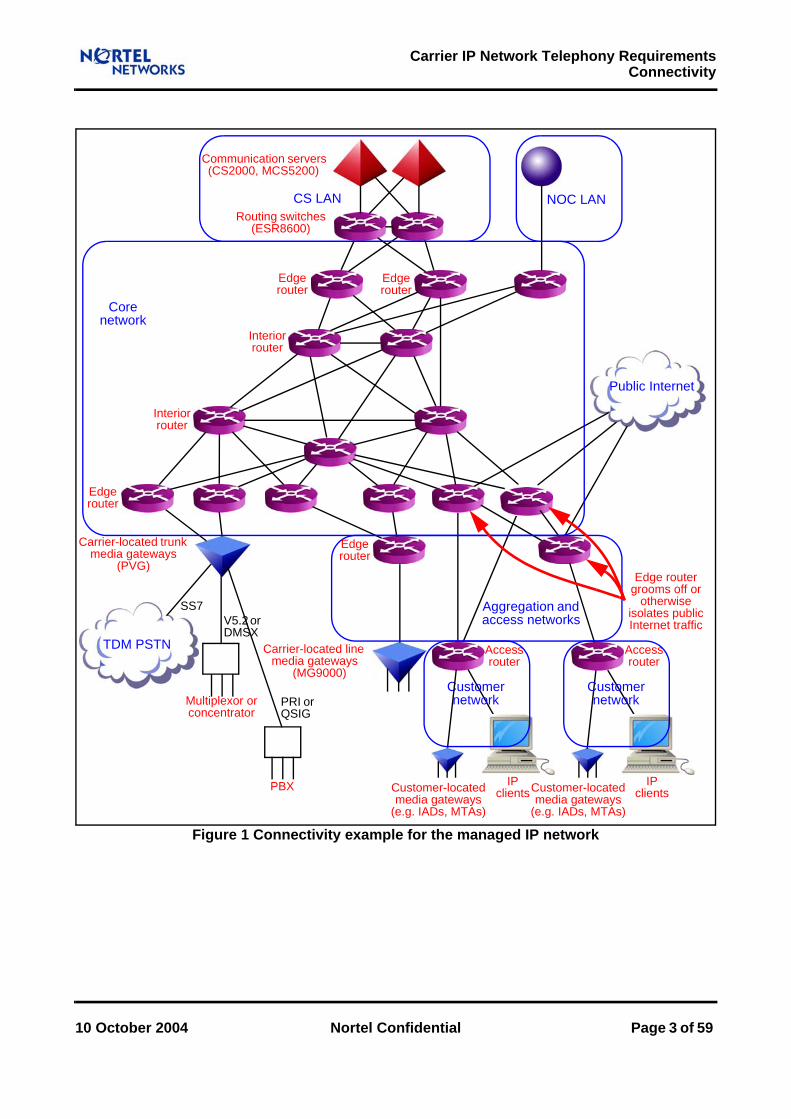
Figure 1 indicates the external connectivity that the managed IP network may need. It is intended as a framework for the discussion in this paper, not as a network design. (In particular, it shows a carrier-located trunk media gateway connecting to the core network and a carrier-located line media gateway connecting to an aggregation network, although the choice of connections actually depends on the required forwarding rates and interface rates.) This framework reflects certain assumptions about the edge of the managed IP network. These assumptions, and alternative views of where the edge might lie, are discussed in section 1.2. As elsewhere in this paper, the aim here is to convey ideas and identify issues, not to suggest that there is only one way of doing things.
Different specifications use different architectures when formulating the connectivity and functions needed for telephony and multimedia over IP. They include, for instance, ones for H.248, H.323, SIP and the documents of the Third Generation Partnership Programme (3GPP). There are, however, many aspects of these architectures that are common to them all; in particular, the 3GPP specifications make extensive use of H.248 for interworking with the PSTN and SIP for constructing the 3GPP IP Multimedia Subsystem (IMS). The framework adopted in this paper can be interpreted in terms of these different specifications and is not confined to any one of them.
Page 2 of 59 Nortel Confidential 10 October 2004
Carrier IP Network Telephony RequirementsConnectivity
Figure 1 Connectivity example for the managed IP network
Edge router grooms off or
otherwise isolates public Internet traffic
PRI or QSIG
Multiplexor orconcentrator
PBX
V5.2 or DMSX
Carrier-located trunkmedia gateways
(PVG)
IPclients
Core network
Edge router
Interior router
Routing switches(ESR8600)
Communication servers(CS2000, MCS5200)
CS LAN
Carrier-located linemedia gateways
(MG9000)
Access router
Access router
Aggregation and access networks
Customer network
Customer network
Customer-locatedmedia gateways
(e.g. IADs, MTAs)
IPclients
Interior router
NOC LAN
Customer-locatedmedia gateways
(e.g. IADs, MTAs)
Edge router
Edge router
Edge router
Public Internet
TDM PSTN
SS7
10 October 2004 Nortel Confidential Page 3 of 59
Carrier IP Network Telephony Requirements Connectivity
1.2 Variations in the Network Edge
1.2.1 Use of Aggregation NetworksThe managed IP network may be structured, not uniform, with at least various aggregation networks and a core network. The aggregation networks provide geographically diverse Points of Presence (PoPs) for external connectivity, while the core network simply provides high-capacity connection. Using aggregation networks provides structure, supports multiplexing and simplifies network management. Structuring the network into appropriate partitions can also enhance security by allowing IP routing between partitions to be restricted to selected points where packet filtering can be applied.
1.2.2 Use of Access NetworksThe customer networks of large customers may be connected directly to the core network routers by links offering high capacity and high functionality (such as trusted traffic differentiation). However, the customer networks of small customers will be connected by links that may have limited capacity and limited functionality; these links are combined in the aggregation networks. (This is likely to be so, in particular, for residential connections using early deployments of DSL modems.) The access links, and even the aggregation networks, may not be controlled by the service provider (when, for instance, certain forms of local loop unbundling are in force). They may affect greatly the quality experienced by end users.
1.2.3 Edge Router Connections with LANsCommunication servers are connected to edge routers through CS LAN routing switches. Figure 1, however, shows remote carrier-located media gateways directly connected to edge routers.
The edge routers to which a remote carrier-located media gateway is attached could be regarded as the hub of a Media Gateway (MG) LAN, rather than as core network devices. To apply the same reasoning in reverse, it would also be possible to regard CS LAN routing switches as core network devices.
However, the following considerations point against doing this:
The CS LAN routing switches are configured to provide essential, dedicated communications capability between communication server components and associated elements, and their ability to do so has been exhaustively tested and verified by Nortel. Traffic not related to the communication servers should not be permitted to traverse the CS LAN, as it might compromise the performance of the communication server system. It is therefore important to retain a distinction between the CS LAN and the core network.
The edge routers may well be delivering other data services, such as IP VPNs, in addition to providing connectivity for the media gateway. The service provider, not Nortel, determines their network roles and configurations. Indeed, depending upon their other requirements, different service providers may deploy different edge routers and these may even be third-party units. It is therefore appropriate to regard edge routers for remote carrier-located media gateways as being in the core network, not in an MG LAN.
Page 4 of 59 Nortel Confidential 10 October 2004

Carrier IP Network Telephony RequirementsConnectivity
1.2.4 Further VLANs Using CS LAN Routing SwitchesThe CS LAN is structured into Virtual LANs (VLANs), each supporting different types of traffic between communication server components and associated elements. The only essential VLANs in a minimal configuration of the CS LAN are the call processing VLAN and the OAM&P VLAN. However, other VLANs may be configured, including:
Media server VLANOne or more media servers are connected to a media VLAN supported by the CS LAN. These media servers can be used to support announcements, conferences and centralised replication functionality for lawful interception; they are collocated with the communication servers when they have provide this support, as their functions are then closely coupled with those of the communication servers. For signalling purposes, the media servers are connected to a CS LAN call processing VLAN.
Media proxy VLANOne or more media proxies are connected to a media VLAN supported by the CS LAN. These media proxies provide Network Address and Port Translation (NAPT) functions that isolate the addresses allocated to customer-located media gateways and clients from each other and from the addresses allocated to media servers and carrier-located media gateways; they are therefore located near the media servers and media gateways where the traffic volumes justify doing so.
Media gateway VLANOne or more media gateways are connected to a media VLAN supported by the CS LAN. If the traffic profile so permitted, this media VLAN could be used by media servers also. For signalling purposes, the media gateways are connected to a CS LAN call processing VLAN.
Moreover, element managers on the CS LAN are connected through the CS LAN routing switches to the client desk tops and higher-level management application servers that access them in order to perform management tasks. These clients reside on a Network Operations Centre (NOC) LAN in the intranet of the service provider. The connections to this LAN are often made directly from the CS LAN routing switches without traversing the core network.
If additional VLANs are attached to the CS LAN routing switches, traffic not related to the communication servers should not be permitted to traverse the CS LAN; in particular, these additional VLANs must not encroach on the routing switch capacity required for the CS LAN.
1.2.5 VLANs Not Using CS LAN Routing SwitchesWhere MCS5200 is the only communication server used (and, in particular, the SS7 and other capabilities of CS2000 are not available) the service provider may choose to attach certain VLANs required in the communication server site direct to the edge routers, without using routing switches. The communication server and its associated media proxies can be reached over these VLANs by traffic from customer networks but can also communicate between themselves over other VLANs to which the customer networks have no access.
10 October 2004 Nortel Confidential Page 5 of 59

Carrier IP Network Telephony Requirements Connectivity
1.3 Implications at the Network Edge
1.3.1 CS LAN Routing Switch ConnectionsCall processing is supported by communication servers attached to the Communication Server (CS) LAN. This is connected to the core network through the CS LAN routing switches.
The CS LAN routing switches are connected to the core network by Gigabit Ethernet or ATM over SDH.
For redundancy, each CS LAN routing switch must have at least two links to the core network (four can be used if required). These redundant physical links must be connected to different edge routers, so that the service undergoes little disruption if either edge router fails.
The traffic using the CS LAN routing switches can include:
Media (or ‘user’ or ‘bearer’) trafficVoice.Tones (upspeeded to G.711 or demodulated using RFC 2833).Fax (upspeeded to G.711 or demodulated using T.38).Modems (upspeeded to G.711).64 Kb/s ISDN clear channel data.
Signalling (or ‘control’) trafficDevice and call control of media devices such as media servers, media gateways, media proxies and IP clients from communication servers (e.g. H.248, MGCP, H.323, SIP).Call control backhauled to communication servers from media gateways (e.g. PRI, QSIG, V5.2).Call control backhauled to communication servers from signalling gateways (e.g. ISUP, TUP).Call control passing between communication servers (e.g. SIP, SIP-T).
Management traffic (e.g. SNMP, DHCP, TFTP).
Not all these types of the following types of media, signalling and management traffic are necessarily present, but the CS LAN provides at least:
A call processing VLAN (also referred to as the ‘CallP’ VLAN) for the communication servers and signalling gateways.
An OAM&P VLAN for the element managers for trusted network elements.
Typically, the CS LAN routing switches also carry media traffic to or from media servers that support announcements, conferences and centralised replication functionality for lawful interception. They may also carry media traffic to or from collocated media gateways and media proxies, and management traffic to or from the Network Operations Centre (NOC), as indicated in section 1.2.
Page 6 of 59 Nortel Confidential 10 October 2004

Carrier IP Network Telephony RequirementsConnectivity
When MCS5200 is used there may be extra traffic types, appropriate to multimedia rather than telephony.
Figure 2 displays both the possible traffic types and the possible connection types (Gigabit Ethernet and ATM over SDH) between the CS LAN routing switches and the managed IP network. (The support for H.323 device and call control traffic assumes that H.245 message contents are carried in H.225.0 messages.) Not all of this traffic necessarily crosses between the CS LAN routing switches and the edge routers; in particular, media servers and signalling gateways are generally collocated with corresponding communication servers.
Figure 2 Traffic presented by the CS LAN
Voi
ce
64 K
b/s
ISD
N
clea
r cha
nnel
da
ta
Mod
ems
UDP
RFC 2684AAL5ATMSDH
MAC
1000 BaseX
LLC
Tone
s
Fax
IP
RTPRTP UDPTL
Links to core network
Intra-routing switch links
1000 BaseX
LLCIP
MAC
100 BaseT
LLCIP
MAC
100 BaseT
LLCIP
MAC
Routingswitch
Routingswitch
Signalling and management traffic
Media trafficEdgerouter
Edgerouter
Cal
l con
trol
pass
ing
betw
een
com
mun
icat
ion
serv
ers
OA
M&
P
RFC 2684AAL5ATMSDH
MAC
1000 BaseX
LLC
UDP TCPIP
UDP
Dev
ice
and
call
cont
rol o
f m
edia
dev
ices
Cal
l con
trol
back
haul
ed
from
med
ia
gate
way
sSCTP
Cal
l con
trol
back
haul
ed
from
sign
allin
g ga
tew
ays
UDPSCTPUDPSCTP
10 October 2004 Nortel Confidential Page 7 of 59
Carrier IP Network Telephony Requirements Connectivity
1.3.2 Remote Carrier Media Gateway ConnectionsMedia gateways are not routers but end systems that must be connected to routers. Nonetheless, Nortel PVG can have integrated into it routing capabilities; alternatively, separate routers, including third-party ones, may be used.
This paper treats routers for remote carrier-located media gateways as edge routers belonging to the core network, though in conceptual terms they could be regarded as the hub of a Media Gateway (MG) LAN that is in turn connected to the core network. As explained in section 1.2, carrier-located media gateways may also be attached to a VLAN supported by the CS LAN routing switches.
The remote carrier-located media gateways are connected to the core network by Gigabit Ethernet or ATM over SDH.
For redundancy, each remote carrier-located media gateway should have two links to the core network. These redundant physical links should be connected to different edge routers, so that the service undergoes little disruption if either edge router fails. A service provider may use one edge router instead of two edge routers, but the failure of the edge router would make the media gateway inaccessible.
The traffic using the remote carrier-located media gateways can include:
Media (or ‘user’ or ‘bearer’) trafficVoice.Tones (upspeeded to G.711 or demodulated using RFC 2833).Fax (upspeeded to G.711 or demodulated using T.38).Modems (upspeeded to G.711).64 Kb/s ISDN clear channel data
Signalling (or ‘control’) trafficDevice and call control of media devices such as media gateways from communication servers (e.g. H.248, MGCP, H.323, SIP).Call control backhauled to communication servers from media gateways (e.g. PRI, QSIG, V5.2).
Management traffic (e.g. SNMP, DHCP, TFTP).
The remote carrier-located media gateways provide:
Interconnections with the PSTN.
Access to PBXs.
Access to multiplexors and concentrators that themselves have direct connections to subscriber lines.
Direct connections to subscriber lines.
Figure 3 displays both the possible traffic types and the possible connection types (Gigabit Ethernet and ATM over SDH) between remote carrier-located media gateways (such as PVGs) and the managed IP network.
Page 8 of 59 Nortel Confidential 10 October 2004

Carrier IP Network Telephony RequirementsConnectivity
Figure 3 Traffic presented by remote carrier-located media gateways
Links to core networkMediagateway
Signalling and management traffic
Media traffic
Voi
ce
64 K
b/s
ISD
N
clea
r cha
nnel
da
ta
Mod
ems
Edgerouter
Edgerouter
UDP
RFC 2684AAL5ATMSDH
MAC
1000 BaseX
LLC
Tone
s
Fax
OA
M&
P
UDP
RFC 2684AAL5ATMSDH
MAC
1000 BaseX
LLC
Dev
ice
and
call
cont
rol o
f m
edia
dev
ices
Cal
l con
trol
back
haul
ed
from
med
ia
gate
way
s
SCTP UDP TCP
IP
IP
RTPRTP UDPTL
10 October 2004 Nortel Confidential Page 9 of 59

Carrier IP Network Telephony Requirements Connectivity
1.3.3 Customer Network ConnectionsCustomer-located media gateways (and, as a special case, IP clients) are connected to the managed IP network through access routers using various protocols which depend on the access links.
There is usually no redundancy in the access networks, except for high-value connections to major enterprise sites. There may, however, be redundancy in the aggregation networks, with (for instance) each edge router being connected to two interior routers.
The traffic using the customer networks can include:
Media (or ‘user’ or ‘bearer’) trafficVoice.Tones (upspeeded to G.711 or demodulated using RFC 2833).Fax (upspeeded to G.711 or demodulated using T.38).
Signalling (or ‘control’) trafficDevice and call control of media devices such as media gateways and IP clients from communication servers (e.g. H.248, MGCP, H.323, SIP).
Management traffic (e.g. SNMP, DHCP, TFTP).
Customer networks also generate public Internet traffic. This should be filtered out (typically at the edge routers or at broadband remote access servers in the aggregation networks) so that it cannot reach communication servers or media gateways.
The access routers support Customer Premises Equipment (CPE) such as
Integrated Access Devices (IADs).
Cable network Multimedia Terminal Adapters (MTAs).
IP clients (dedicated terminals and soft clients using PCs)
Figure 4 displays both the possible traffic types and some possible connection types (Gigabit Ethernet and ATM over DSL) between access routers and the managed IP network. (The support for H.323 device and call control traffic assumes that H.245 message contents are carried in H.225.0 messages.) The treatment of ATM over DSL represents just one possibility, which uses ‘Classical IP over ATM’; it is not intended to preclude various alternatives involving the use of PPP over ATM and Ethernet over ATM.
Page 10 of 59 Nortel Confidential 10 October 2004

Carrier IP Network Telephony RequirementsConnectivity
Figure 4 Traffic presented by customer networks
1.4 Traffic TypesThe various connections at the network edge require telephony over IP to support various traffic types. Table 1 indicates which traffic types are needed at each connection to support telephony over IP.
Other traffic types also use the managed IP network (in VPNs, for instance), because there may be other services to end users and there is management and control traffic for the managed IP network itself (such as ‘keep alive’ messages and routing updates).
Links to core network100 BaseT
LLCIP
MAC
100 BaseT
LLCIP
MAC
Accessrouter
Signalling and management traffic
Media traffic
Voi
ce
Fax
RTP
Edgerouter
UDP
RFC 2684AAL5ATMDSL
MAC
1000 BaseX
LLC
Tone
s
OA
M&
P
RFC 2684AAL5ATMDSL1000 BaseX
LLC
UDP TCP
IP
IP
UDPTL
UDP
Dev
ice
and
call
cont
rol o
f m
edia
dev
ices
MAC
10 October 2004 Nortel Confidential Page 11 of 59

Carrier IP Network Telephony Requirements Connectivity
Traffic typeCS LAN Routing
Switch Connections
Remote Carrier Media Gateway
Connections
Customer Network
Connections
Voice Yes Yes Yes
TonesYes (upspeeded to
G.711),Yes (demodulated using RFC 2833)
Yes (upspeeded to G.711),
Yes (demodulated using RFC 2833)
Yes (upspeeded to G.711),
Yes (demodulated using RFC 2833)
FaxYes (upspeeded to
G.711),Yes (demodulated
using T.38)
Yes (upspeeded to G.711),
Yes (demodulated using T.38)
Yes (upspeeded to G.711),
Yes (demodulated using T.38)
Modems Yes Yes No
64 Kb/s ISDN clear channel data Yes Yes No
Device and call control of media devices Yes Yes Yes
Call control backhauled from media gateways Yes Yes No
Call control backhauled from signalling gateways Yes No No
Call control passing between communication servers Yes No No
OAM&P Yes Yes Yes
Table 1 Connectivity requirements at the network edge
Page 12 of 59 Nortel Confidential 10 October 2004
2 CapacityCapacity requirements are determined by the extent to which users the users of a service can be served without preventing other users of the same or a different service from being served. For the TDM PSTN these requirements are summarised in a Grade of Service (GoS) which is the probability that calls are blocked. They influence the network design by demanding that the network elements and network links themselves have particular capacities (so, for instance, the switches must be able to process calls at given rates).
Similarly, capacity requirements for services offered over a managed IP network impose demands both on the end points, such as the communication servers, and on the network links. However, the demands on the end points are not due to the managed IP network itself, so they are outside the scope of this paper. For the managed IP network there is one major influence on the capacity required; this is the bandwidth needed to support traffic of a given type passing between each source and destination. The bandwidth needed by voice is identified in section 2.1.
The bandwidth needed varies between and within traffic types in accordance with the performance requirements. The overall bandwidth can be calculated in the way discussed in section 2.2 and estimated in the way described in section 2.3.
2.1 Considerations for Voice TrafficTable 2 summarises how the bandwidth required by one voice call can be calculated for some common codecs, inter-packet intervals and link layers. The bandwidth requirements should be understood as follows:
They apply separately in each direction.
They assume that there is no silence suppression.
They include inter-frame gaps and IEEE 802.1Q fields for Ethernet.
They exclude any overhead for SDH.
They consider just the media traffic, not the signalling and management traffic.
Multiple ‘stacked’ link layers, such as those for PPP over ATM and Ethernet over ATM, require correspondingly greater bandwidths.
A service provider can choose to reduce costs by reducing the bandwidth requirements in the following ways, all of which may reduce perceived voice quality:
Using longer inter-packet intervalsThe RTP, UDP and IP overheads are the same for each packet regardless of sample size, so less bandwidth is required if there are fewer packets, even although each packet must collect voice samples for a longer interval. Thus 10 ms inter-packet intervals require 32 Kb/s for RTP, UDP and IP overheads, whilst 20 ms inter-packet
10 October 2004 Nortel Confidential Page 13 of 59

Carrier IP Network Telephony Requirements Capacity
intervals require 16 Kb/s. However, using longer inter-packet intervals can increase delay and distortion (because, for instance, it increases the impact of packet loss).
Using voice compressionG.711 requires 64 Kb/s, whilst G.729, for example, requires only 8 Kb/s, so using voice compression can save bandwidth. (G.729 differs from G.729A mainly by using a more complicated algorithm.) However, the saving is not as great as this example might suggest, because bandwidth is still needed for RTP, UDP and IP overheads and for traffic other than voice traffic, such as fax traffic, that does not benefit from voice compression. Moreover, voice compression can increase delay and distortion, especially if it is applied more than once in the traffic path (as it may be, for instance, in mobile and international calls, or in conferences).
Using silence suppressionNot transmitting voice packets when a participant in a conversation is silent can reduce the bandwidth required by 40% (depending on the background sound). (Even if there is no background sound, there remains traffic, amounting to one IP packet of 41 bytes - 42 bytes each second to indicate silence insertion detection.) However, between 20 and 30 voice calls are likely to be needed to make silence suppression effective: when the number of users is lower than this, the likelihood of simultaneous talk-spurts is too high to save bandwidth consistently. Moreover, silence suppression can increases distortion slightly, by clipping speech or varying what speakers hear, especially when there is background sound.
Using header compressionHeader compression can reduce the RTP, UDP and IP overheads to 2 bytes - 5 bytes for each packet. However, currently header compression techniques need additional processing (so they can add delay) and can be unstable if there is packet loss (so they can add distortion). They are not recommended except perhaps for use on low bandwidth (less than 1 Mb/s) links.
Page 14 of 59 Nortel Confidential 10 October 2004

Carrier IP Network Telephony RequirementsCapacity
L
M
ink layerCodec = G.711 Codec = G.729
inter-packet interval = 10 ms
inter-packet interval = 20 ms
inter-packet interval = 10 ms
inter-packet interval = 20 ms
None
Voice packet size 80 bytes 160 bytes 10 bytes 20 bytes
RTP / UDP / IP header size 40 bytes 40 bytes 40 bytes 40 bytes
IP packet size 120 bytes 200 bytes 50 bytes 60 bytes
Bandwidth 96.0 Kb/s 80.0 Kb/s 40.0 Kb/s 24.0 Kb/s
MPLS /POS
MPLS / PPP header size 11 bytes 11 bytes 11 bytes 11 bytes
Total packet size 131 bytes 211 bytes 61 bytes 71 bytes
Bandwidth 104.8 Kb/s 84.4 Kb/s 48.8 Kb/s 28.4 Kb/s
Ethernet
LLC / MACheader size 42 bytes 42 bytes 42 bytes 42 bytes
Total packet size 162 bytes 242 bytes 92 bytes 102 bytes
Bandwidth 129.6 Kb/s 96.8 Kb/s 73.6 Kb/s 40.8 Kb/s
ulti-class Multi-link
PPP
Multi-class Multi-link PPP header size
9 bytes (short),11 bytes (long
9 bytes (short),11 bytes (long)
9 bytes (short),11 bytes (long)
9 bytes (short),11 bytes (long)
Total packet size 129 bytes (short),131 bytes (long)
209 bytes,211 bytes (long)
59 bytes,61 bytes (long)
69 bytes,71 bytes (long)
Bandwidth 103.2 Kb/s (short),104.8 Kb/s (long)
83.6 Kb/s (short),84.4 Kb/s (long)
47.2 Kb/s (short),48.8 Kb/s (long)
27.6 Kb/s (short),28.4 Kb/s (long)
FrameRelay
RFC 2427 / Q.922header size 7 bytes 7 bytes 7 bytes 7 bytes
Total packet size 127 bytes 207 bytes 57 bytes 67 bytes
Bandwidth 101.6 Kb/s 82.8 Kb/s 45.6 Kb/s 26.8 Kb/s
AAL5 /ATM
RFC 2684 / AAL5header size
8 bytes (VC based),
16 bytes (LLC encapsulated)
8 bytes (VC based),
16 bytes (LLC encapsulated)
8 bytes (VC based),
16 bytes (LLC encapsulated)
8 bytes (VC based),
16 bytes (LLC encapsulated)
ATM cell count 3 cells 5 cells 2 cells 2 cells
Total packet size 159 bytes 265 bytes 106 bytes 106 bytes
Bandwidth 127.2 Kb/s 106.0 Kb/s 84.8 Kb/s 42.4 Kb/s
Table 2 Capacity requirements due to voice bandwidth
10 October 2004 Nortel Confidential Page 15 of 59

Carrier IP Network Telephony Requirements Capacity
2.2 Bandwidth DefinitionsAs section 2.1 illustrates for voice traffic, the principal measures used in calculating the bandwidth needed are the packet size and the packet rate. (The packet rate is derived from the inter-packet interval; for example, it is 100 p/s if the inter-packet interval is 10 ms.) However, voice traffic is particularly straightforward: unless there is silence suppression, voice traffic usually has a constant bit rate that is achieved by emitting packets for which the packet size and packet rate stay constant, so the bandwidth needed by voice traffic can be calculated just by multiplying the packet size by the packet rate. Traffic for which the packet size or the packet rate is not constant presents problems: the bandwidth needed would be over-estimated if it were calculated by multiplying the maximum packet size by the maximum packet rate and would be under-estimated if it were calculated by multiplying the average packet size by the average packet rate.
Moreover, to satisfy performance requirements, a network link must have a bandwidth exceeding that calculated by multiplying a packet size by a packet rate. The extent of the excess required depends on the variability of the packet size and packet rate: on some networks voice traffic may require much less excess bandwidth than bursty traffic having performance requirements like those for voice. (These performance requirements demand stringent upper bounds on the maximum delay and packet loss ratio for the traffic.)
Consequently, bandwidth calculations should take into account the distributions of the packet size and packet rate. The formal way of doing this results in the ‘effective bandwidth’. The effective bandwidth describes the bandwidth that must be supplied to satisfy performance requirements (which are upper bounds on the maximum delay and packet loss ratio) for a given traffic volume. It can depend on characteristics of the network elements and network links such as buffer size, traffic mix and scheduling policy. However, in many respects it is well behaved; for instance, an upper bound on the effective bandwidth for multiple independent traffic flows can be obtained by adding together upper bounds on the effective bandwidths for the individual flows.
As section 3.3 indicates, the traffic types found in telephony over IP tend either to have constant packet sizes and constant packet rates or to have less demanding performance requirements than voice. (Even fax traffic demodulated using T.38 is often transmitted with a constant packet size and a constant packet rate.) Accordingly the bandwidth that must be supplied can be estimated from the bandwidth needed for voice traffic by making appropriate allowances for other types of traffic. This way of estimating the bandwidth, with no overt reference to the calculation of effective bandwidth, is described in section 2.3.
2.3 Bandwidth EstimationsTable 2 indicates the bandwidth required in one direction by one voice call. Often data network engineering is concerned implicitly or explicitly with the bandwidth required in both directions, because its primary focus is the switching rates of the nodes, not the transmission rates of the links; this bidirectional figure is double the unidirectional one, for conventional conversations (as opposed to lectures, for instance).
The bandwidth for voice traffic is calculated by multiplying the bandwidth required for one voice call by the number of calls expected. However, telephony over IP depends on other types of traffic, as identified in section 1.4. The bandwidth for voice traffic can be converted into the bandwidth for the overall traffic by noting the following:
Page 16 of 59 Nortel Confidential 10 October 2004

Carrier IP Network Telephony RequirementsCapacity
Other forms of media traffic have different bandwidth requirements. In particular, traffic for tones upspeeded to G.711, fax upspeeded to G.711, modems upspeeded to G.711 and 64 Kb/s ISDN clear channel data is treated as if is voice traffic without compression or silence suppression and with the same inter-packet interval as the actual voice traffic. In addition, tones demodulated using RFC 2833 can be treated in this way, although they usually require less bandwidth unless the corresponding audio encodings are also transmitted. For simplicity, fax demodulated using T.38 can be treated in this way, although in reality its bandwidth requirements depend on the fax rate and redundancy level. (For example, one implementation of V.17 needs a packet rate of 67 p/s in one direction and a IP packet size of 75 bytes - 204 bytes, depending on the level of redundancy, before the addition of link layer overheads.)
RTP streams usually induce RTCP streams flowing in the opposite direction. The traffic due to these RTCP streams may amount to only one IP packet of 80 bytes each second for each RTP stream; however, RFC 3550 suggests that 5% of the bandwidth may be devoted to RTCP.
The network must accommodate signalling and management traffic. Typically the proportion of signalling and management traffic is higher in an IP network than in an equivalent TDM network, because there are more messages (generated by more distributed network elements) and because the messages are often expressed as text instead of with ASN.1 encoding rules. Accommodating signalling and management traffic entails increasing the bandwidth by a suitable fraction (which can be 5% - 10%, at least if signalling traffic between communication servers is included).
The considerations above apply irrespective of the network size and topology. They indicate that the bandwidth for RTP media traffic may need to be multiplied by 110% - 115% to accommodate RTCP media traffic, signalling traffic and management traffic as well as RTP media traffic. (The bandwidth for RTP media traffic itself is obtained by assuming that all the RTP media traffic, other than voice encoded as G.729, can be treated in bandwidth calculations as if it is voice encoded using G.711; how accurate this is depends on the expected modes of use of the network, which determine such matters as the fax rate and redundancy level.)
Here these points are illustrated by an example. Table 2 indicates that each direction of the media traffic for one voice call using G.711 with 10 ms samples without silence suppression requires 104.8 Kb/s when the IP network uses MPLS over POS. Consequently if there are to be 80000 simultaneous calls, for instance, 8.4 Gb/s will be required in each direction. When this figure is modified to accommodate RTCP media traffic, signalling traffic and management traffic as well as RTP media traffic, it rises to 9.2 Gb/s - 9.6 G/s. The corresponding bidirectional figure is 18.4 Gb/s - 19.3 Gb/s.
The bandwidth requirements are also affected by considerations that depend on the network size and topology and that arise during network design. These are the following:
The network needs to avoid congestion. The design has to accommodate the forecast growth in demand and to ensure that certain upper bounds on the maximum delay and packet loss ratio are not exceeded. Often all of the routes are required to have no more than 60% - 80% utilisation even after a failure (so if there is load balancing between two paths offering protection then in normal operation each path will have no more than 30% - 40% utilisation).
The network needs to provide protection. The provision of alternative paths for protection is likely to introduce a significant extra factor. Sometimes all of the paths have to be 1:1 protected independently of each other.
10 October 2004 Nortel Confidential Page 17 of 59
Carrier IP Network Telephony Requirements Capacity
The different services on the network as a whole can have bandwidth requirements that are interrelated, for the following reasons:
The bandwidth required for avoiding congestion and providing protection may differ for services having different volumes and values. There are ways of sharing network capacity between services so that the bandwidth required is not dictated by aggregate traffic demands but instead recognises the differences in requirements between different services.
The network may be utilised to different degrees by different services at different hours of the day and on different days of the week. The service provider may be able to share network capacity between two services for which the maximum traffic volumes occur at different times or within one service for which the users are in different time zones.
Different transmission systems offer different degrees of granularity in the bandwidth available. After all of the link layer multiplexing above the transmission layer is included by the bandwidth calculations there remains an overhead due to rounding up the bandwidth required to the smallest possible container in the transmission hierarchy. This might be an SDH Virtual Container (VC), for example.
Page 18 of 59 Nortel Confidential 10 October 2004

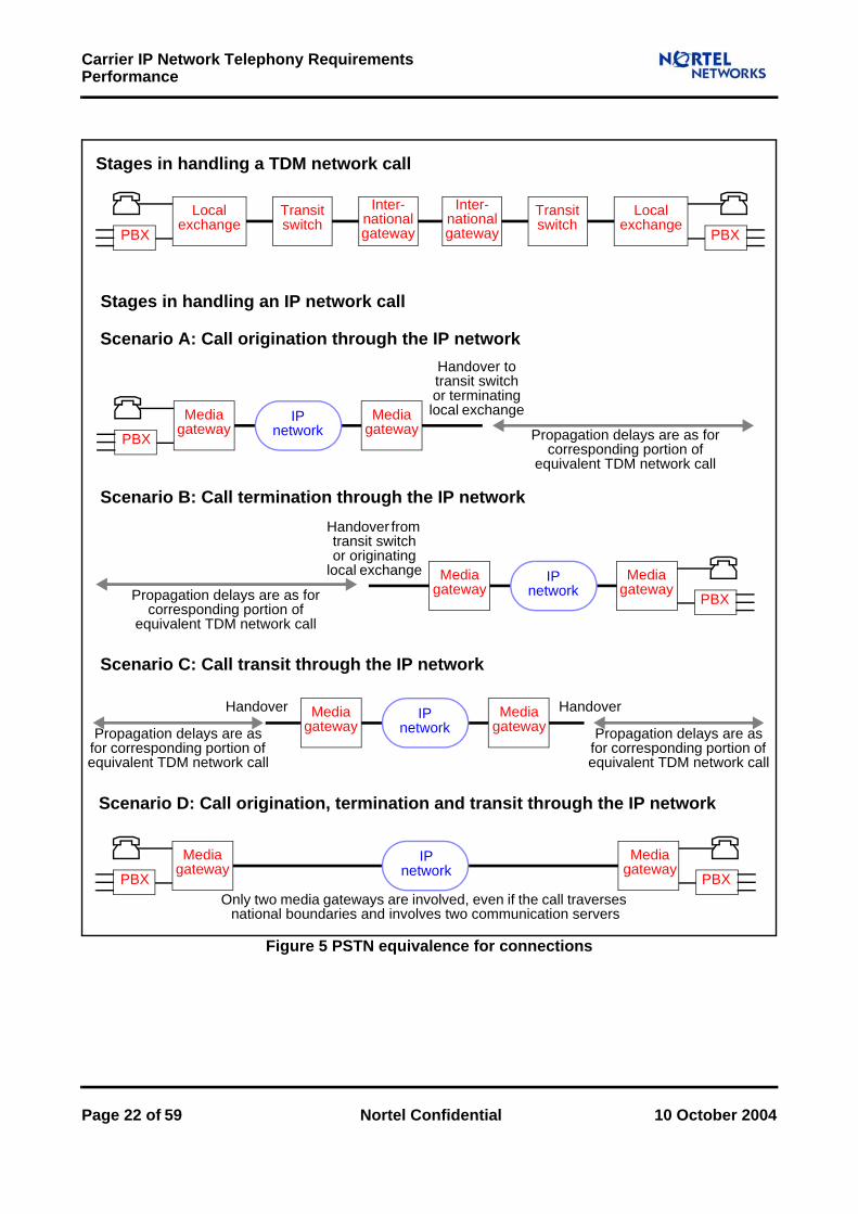
3 PerformanceThe aim of ‘PSTN equivalence’ for carrier telephony over IP is that quality should not be perceptibly worse when traffic is carried over the managed IP network than when traffic is carried over the TDM PSTN. One aspect of this quality is termed ‘performance’ in this paper; it concerns the extent to which services that are operational meet the sensory expectations of users. Examples where performance is important include the audibility of voice, the legibility of fax and the timeliness of tone generation. The implications for voice quality are explored in section 3.1.
The quality experienced by the users of a service can be predicted by characterising the network using certain metrics. The quality is then regarded as acceptable if the values of these metrics for the network are no worse than certain targets. Because different traffic types (for media, signalling and management) affect the perceived quality to different extents, the targets can be different for different traffic types. However, typically the targets apply equally to all sources and destinations of traffic served by the network, at least when the sources and destinations are not too far apart. Specifically, for performance, metrics are defined in section 3.2 and targets for some of these metrics are specified for each relevant traffic type in section 3.3. Notes explaining the targets are provided in section 3.4, indexed by the numbered cross-references. Where possible the targets are derived from standards for the TDM PSTN, so that the requirements on the managed IP network due to PSTN equivalence can be understood. Mechanisms at the edge of the managed IP network (such as packet loss concealment), as well as changes in the priorities of users, may allow these requirements to be relaxed.
The managed IP network may need to apply different forwarding treatments to packets having different traffic types, in order to satisfy performance requirements most cost-effectively. (In particular, for every traffic type there must be no unacceptable degradation in performance if capacity is shared between different traffic types.) The ways of doing this imposes some constraints at the edge of the managed IP network; these and other constraints due to the performance requirements are outlined in section 3.5.
3.1 Considerations for Voice TrafficThe PSTN currently determines user expectations of voice quality. However, some service providers may be able to achieve performance that is acceptable to the intended users without achieving full PSTN equivalence for every target. An adequate solution may be preferable to an ideal solution for reasons of cost or convenience (just as mobile phone users accept performance that is generally inferior to that of fixed lines). Furthermore, a solution intended for a particular environment (for financial dealing networks, for example), not for general business or residential applications, may need to satisfy quite different requirements.
Voice quality is affected by distortion and delay. As switches introduce little delay, most of the delay in the TDM PSTN is due to the propagation time of the transport medium, which is proportional to distance for a given medium. Propagation time contributes equally to delay for TDM and IP networks. It can therefore be discounted when estimating
10 October 2004 Nortel Confidential Page 19 of 59

Carrier IP Network Telephony Requirements Performance
the impact on quality of replacing a TDM connection by an IP one on part or all of the route taken by a call.
A network having low delay may be able to tolerate the introduction of extra delay without significant degradation in the voice quality, provided that the total delay remains less than 150 ms - 200 ms. (The degradation is very small below 150 ms, which is the figure widely cited, but also remains small until about 175 ms - 200 ms, when it starts to become much more severe.) By contrast, introducing extra distortion always degrades the voice quality. Distortion in the TDM PSTN is associated mainly with echo signals, compression codecs in the core network (in international gateways and submarine links, for example) and compression codecs in the access network (typically for mobile phones). Replacing a TDM connection by an IP one is more likely to increase distortion than to decrease it, except in some cases where international links or active echo control devices are used.
The delay and distortion in voice calls are affected by various factors that are specific to IP networks. They include the following:
Media gateway processingVoice traffic incurs a delay just by entering and leaving the IP network, owing to the processing that takes place in the media gateways. This delay (or ‘latency’) must use part of the end-to-end delay budget and will therefore reduce the budget available for traversing the IP network itself. The delay depends on the codec and on the inter-packet interval, which determines the duration of the speech utterance that a packet encodes. In addition, the use of voice compression or silence suppression in the media gateways creates distortion that is characteristic of the codec chosen, as indicated in section 2.1.
Packet delay variationPacket delay variation (or ‘jitter’) arises from queuing and routing as packets traverse the network. Packet delay variation is converted into delay at any network function that reshapes the traffic and in particular at a receiving media gateway that uses a ‘jitter buffer’. This holds packets for a time at least equal to an acceptable upper bound on the packet delay variation before playing them out, with the effect that gaps can be removed from the speech, at the expense of adding delay. Packets that arrive later than this acceptable upper bound are lost because they miss their playout times. Hence packet delay variation and packet loss are closely related.Packet mis-sequencingPackets that follow different routes may be delivered out of sequence. In this case, if the packets are not to be lost, the receiving media gateway jitter buffer must be capable of holding enough received packets to re-order them into the correct sequence before they are played out. Doing this adds delay. A preferable approach is to make all the media packets for each call follow the same route in normal conditions and to require that the routers themselves do not transmit packets in incorrect orders across their backplanes. With this approach the jitter buffer need not re-order packets.Packet lossAny loss of packets between media gateways will cause a gap in speech utterances, which is a form of distortion. The amount of distortion will depend on the distribution of lost packets, the choice of codec and the packet size. Packet loss in the managed IP network is caused by congestion in routers, so avoiding packet loss requires designing the network itself, not just using the media gateways.
Page 20 of 59 Nortel Confidential 10 October 2004

Carrier IP Network Telephony RequirementsPerformance
Appropriately chosen media gateways support packet loss concealment, to mitigate the effect of packet loss on voice quality. However, even if there is packet loss concealment, packet loss can be deleterious: packet loss concealment can be ineffective against long bursts of packet loss, and some traffic types, such as that for circuit emulation over IP using a ‘pseudo-wire’, tolerate less packet loss than voice. Consequently, the network should be designed so that in normal operation there is a low probability of packet loss through congestion from excess traffic entering the network or routes changing in the network. This probability defines a maximum for the packet delay variation that is used to configure receiving media gateway jitter buffers.
The E-model described in G.107 can be used to estimate voice quality for both TDM networks and IP networks (and indeed hybrid networks). An E-model calculation for a reference connection uses the delay and distortion assumed for the components to provide a measure of voice quality that is denoted by ‘R’: values of R above 80 are deemed to be satisfactory and values of R above 90 are deemed to be very satisfactory. (The maximum value of R obtainable for narrowband voice on the TDM PSTN is 93.2.) This objective measure of voice quality has been validated against subjective user assessments.
Subjective user assessments themselves have various limitations [9]. For instance, a Mean Opinion Score (MOS), tends to be difficult to use generally, because the experimental conditions and objectives are embedded in the results and even the five point scale is interpreted differently in different countries.
Figure 5 illustrates the reference connections for which PSTN equivalence is recommended. The E-model can be used to predict the voice quality provided over the TDM and IP connections. In this respect it is most useful in making relative assessments that compare the voice quality provided over a TDM connection with that provided over the corresponding IP connection, not in making absolute judgements about voice quality.
10 October 2004 Nortel Confidential Page 21 of 59
Carrier IP Network Telephony Requirements Performance
Figure 5 PSTN equivalence for connections
Local exchange
PBX
Scenario A: Call origination through the IP network
Stages in handling a TDM network call
Handover to transit switch or terminating local exchange
Propagation delays are as for corresponding portion of
equivalent TDM network call
Inter-nationalgateway
Transit switch
Local exchange
PBX
Inter-nationalgateway
Transit switch
Media gateway
PBXIP
networkMedia
gateway
Stages in handling an IP network call
Scenario B: Call termination through the IP networkHandover from transit switch or originating
local exchange
Propagation delays are as for corresponding portion of
equivalent TDM network call
Media gateway
PBXIP
networkMedia
gateway
Scenario C: Call transit through the IP network
Propagation delays are as for corresponding portion of equivalent TDM network call
Media gateway
IP network
Media gateway
Scenario D: Call origination, termination and transit through the IP network
Only two media gateways are involved, even if the call traverses national boundaries and involves two communication servers
Media gateway
PBXIP
network
Propagation delays are as for corresponding portion of equivalent TDM network call
HandoverHandover
Media gateway
PBX
Page 22 of 59 Nortel Confidential 10 October 2004

Carrier IP Network Telephony RequirementsPerformance
3.2 MetricsThe factors that affect delay and distortion in voice calls and that are described in section 2.1 can be used to define performance metrics for networks. Moreover, performance metrics that exist for TDM networks can be supplemented and re-interpreted for IP networks. The performance metrics that need to be considered are as follows:
Maximum delayThe maximum delay is the long term maximum delay to the traffic that is not regarded as lost (of a given type from a given source to a given destination). (Thus the maximum delay, like all the other performance metrics considered here, is a one-way figure, from one source to one destination.) A packet is regarded as lost when its delay is worse than the maximum delay. (A packet that never arrives is viewed as having an infinite delay.) Consequently the packet loss ratio is the probability that a packet will have a delay worse than the maximum delay.The maximum delay arises from:
Distance-related propagation.Switching in TDM networks.Sample collection, encoding, queuing, serialisation, buffering and decoding in media gateways.Switching and routing in IP networks.
Nortel plans networks with a transmission propagation delay of 5 µs/Km, in accordance with G.114. This accounts for all optical transmission equipment (cross-connections, regenerators, repeaters and retiming) and distance-related transfer delays (except for bit delay variation at the transmission level). The metric is provided by the maximum delay, not the average delay, in order to be most relevant to users; however, some standards, such as Y.1540, refer to the average delay. If the metric were provided by the average delay, then the maximum delay could be estimated from the average delay (for traffic that is not regarded as lost) and packet loss ratio when a particular statistical distribution is assumed.
Packet delay variationThe packet delay variation is the accumulation (or ‘convolution’) of all variable packet delays in the paths taken by the traffic (of a given type from a given source to a given destination). Variable packet delays are due to queuing and routing, so they depend on the traffic shape and load, whilst constant packet delays apply equally to all the traffic.Because the packet delay variation contributes to the delay, formally there is no need to specify a target for it; choosing an upper bound for it becomes a design decision. However, there are specific features of media packets having high priority and small size that influence packet delay variation. These considerations are especially relevant to voice (and to 64 Kb/s ISDN clear channel data, which may be used for voice).Unless there is silence suppression, voice traffic has a constant packet size and a constant packet rate. Consequently, when link speeds are higher than 10 Mb/s and router output links are loaded to 80%, the packet delay variation of voice traffic will be acceptably low, provided that the packets follow the same path.
10 October 2004 Nortel Confidential Page 23 of 59

Carrier IP Network Telephony Requirements Performance
The principal contribution to packet delay variation in the core network will be the changing call pattern in the network, but this is almost constant for the lifetime of an individual call. Much more significant is the packet delay variation in access networks that have low bandwidth links, where both the maximum delay and the packet delay variation can become excessive unless media traffic has high enough priority and data traffic is well enough fragmented.Receiving equipment normally compensates by configuring a jitter buffer for the upper bound on the packet delay variation that the network is designed to tolerate; when the implementation of the receiving equipment places a limit on the size of the jitter buffer, the network must be designed so that the packet delay variation does not exceed that limit. The packet loss ratio then stays beneath its target.Adaptive jitter buffer algorithms that change the compensation in silent periods (through packet loss or speech activity signalling) can reduce the average delay, but not the maximum delay that the jitter buffer is designed to accommodate.Bit delay variation in the TDM network is insignificant compared with packet delay variation in the IP network.
Packet mis-sequencing ratioThe packet mis-sequencing ratio is the long term proportion of the packets that are mis-sequenced on the paths taken by the traffic (of a given type from a given source to a given destination). Such packets are the ones delivered out of sequence. Because the packet mis-sequencing ratio contributes to the packet delay variation, formally there is no need to specify a target for it: choosing an upper bound for it becomes a design decision.When packets can be delivered out of sequence, either the jitter buffer in the receiving equipment must be large enough to allow the sequence to be restored (and packets will be delayed before being played out) or the packets will be lost.
Packet loss ratioThe packet loss ratio is the long term proportion of the packets that are lost on the paths taken by the traffic (of a given type from a given source to a given destination). It is therefore the probability that a packet will have too large a delay.Packet loss varies in distribution according to the root causes. Packet loss due to background errors may be closer to a random distribution than the channel error bursts that induce it, because of the relative lengths of channel error bursts and packets. Packet loss due to congestion is likely to occur in bursts, because congestion endures while several packets arrive. The burst length for a individual traffic flow depends on the inter-packet interval. Experiments [7] indicated that, for the Internet, the length of a burst can have a mean of 2.5 packets for an inter-packet interval of 8 ms, a mean of 1.7 packets for an inter-packet interval of 20 ms and a mean of 1.3 packets for an inter-packet interval of 50 ms. The burst length distribution can have a long tail, although most bursts lasts less than 1 second.In some circumstances bursts of packet losses can have more serious effects than individual packet losses. For instance, packet loss concealment does not protect voice against bursts of packet loss of more than 40 ms - 60 ms. (Prolonged disruption from packet loss can lead to dropped calls and is regarded as related more closely to dependability than to performance.) To impose requirements that reduce the incidence of packet loss bursts of (say) 3 packets, an upper bound for the packet loss ratio could be made be 3 times more demanding than would be required for single packets.
Page 24 of 59 Nortel Confidential 10 October 2004

Carrier IP Network Telephony RequirementsPerformance
Bit error ratioThe Bit Error Ratio (BER) is the long term proportion of the bits that are errored in the traffic (of a given type from a given source to a given destination). The Block Error Ratio is the long term proportion of blocks that are errored, where a block is errored when the number of erroneous bits exceeds a specified threshold. (The number of bits in the block and the threshold may depend on the bit rate.) The Block Error Ratio is potentially more useful than the Bit Error Ratio, because it is easier to measure for certain transmission systems and provides performance indicators that take into account channel characteristics.An Errored Second (ES) is a second in which at least one bit is errored; the Errored Second Ratio (ESR) is the proportion of ESs that occur in transmitting data over a specified distance for a specified interval of time that is usually fairly long.A Severely Errored Second (SES) is a second in which the proportion of the bits that are errored is at least 1 x 10⁻³; the Severely Errored Second Ratio (SESR) is the proportion of SESs that occur in transmitting data over a specified distance for a specified interval of time that is usually fairly long.Data traffic using the TDM PSTN is judged according to targets like those defined in V.53 and G.821. These are upper bounds on the BER, ESR or SESR. Achieving PSTN equivalence entails matching these targets when the data traffic is carried in packets (effectively using circuit emulation) over the IP network instead of directly over the TDM PSTN; in the IP network the errors are due not just to equipment and transmission noise but also to packet loss. Hence upper bounds on the BER, ESR or SESR are used in this paper to define packet loss ratio targets (which are upper bounds on the packet loss ratio) for the IP network, not as targets on their own. The circuit emulation over IP considered here does not apply error correction to the packets, so all bit errors not corrected by the underlying transmission can be treated as inducing packet losses. Conversely, all packet losses from the emulating traffic induce bit errors. In fact, in any “suitably long” time interval, the number of errored bits is the mean packet size multiplied by the number of lost packets and the number of bits is the mean packet size multiplied by the number of packets, so the proportion of errored bits is the proportion of lost packets.Hence, for a circuit emulated over IP, the BER is actually the packet loss ratio. Furthermore, when the mean packet size is “low enough” to ignore packets straddling one second intervals, an ES is a second in which at least one packet is lost and an SES is a second in which the proportion of the packets that are lost is at least 1 x 10⁻³. (In particular, if the inter-packet interval is at least 1 ms, all of the packet losses give rise to SESs.)
3.3 TargetsTable 3 summarises end-to-end performance targets for the traffic types identified in section 2.1 for which the quality is intended to be not perceptibly worse when an IP network is used than when the TDM PSTN is used. As far as possible they are derived from targets that have been standardised for the TDM PSTN, rather than from targets that have been suggested for IP. Several of them are tentative, as the standards taken together are often incomplete and sometimes inconsistent; for these targets the methods of derivation are perhaps more significant then the targets themselves, because the targets for the TDM PSTN are not always directly applicable to IP, especially when they concern international signalling and data links. The targets are presented so that service providers
10 October 2004 Nortel Confidential Page 25 of 59

Carrier IP Network Telephony Requirements Performance
can make conscious choices about the levels of performance that users will accept and that networks should provide, without necessarily having to achieve full PSTN equivalence.
The targets cover the entire network portion for which there is intended to be PSTN equivalence, including TDM links, communication servers, media gateways and element managers. However, whereas the end points for the media traffic are associated with the user terminals, the end points for the signalling and management traffic are associated with communication servers, media gateways and element managers. Consequently figures for particular sequences of signalling messages across sequences of network elements are composed using reference connections as in Q.708; these sequences include ones that have effects immediately perceptible to users (such as dial tone generation, “alerting” sending and “answering” sending).
The performance metrics have values that depend to some degree on the lengths of the paths between the source and the destination of the traffic. (The maximum value of the length of a path across the network is the ‘network span’; in G.826 this is taken to be 25% more than the air-route diameter of the network, for terrestrial paths across a network having a diameter of more than 1200 Km, but in some IP networks it can be at least double the air-route diameter.) Consequently the corresponding targets may be more or less attainable, depending on the network span of the network under consideration. The targets proposed in this paper are intended to be appropriate to reference connections across a network having a span of 3000 Km, which can accommodate many national networks.
Traffic type Upper bound on the maximum delay
Upper bound on the packet loss ratio
Voice 150 ms [P1] 5 x 10⁻³ [P11]
Tones 400 ms [P2]1 x 10⁻³ (upspeeded to
G.711),5 x 10-3 (demodulated using RFC 2833) [P12]
Fax 400 ms [P3]4 x 10⁻⁵ (upspeeded to
G.711),5 x 10-4 (demodulated
using T.38) [P13]
Modems 600 ms [P4] 2 x 10⁻⁵ [P14]
64 Kb/s ISDN clear channel data 150 ms [P5] 2 x 10⁻⁵ [P15]
Device and call control of media devices 100 ms [P6] 2 x 10⁻⁴ [P16]
Call control backhauled from media gateways 100 ms [P7] 2 x 10⁻⁴ [P17]
Call control backhauled from signalling gateways 100 ms [P8] 2 x 10⁻⁴ [P18]
Call control passing between communication servers 100 ms [P9] 2 x 10⁻⁴ [P19]
OAM&P 600 ms [P10] 1 x 10⁻² [P20]
Table 3 Performance targets
Page 26 of 59 Nortel Confidential 10 October 2004

Carrier IP Network Telephony RequirementsPerformance
3.4 Notes[P1] Upper bound on the maximum delay for voice
The target quoted is drawn from G.114, which also indicates how perceived quality declines when the delay exceeds 150 ms. Below this threshold, voice quality is not very sensitive to delay if echo is controlled well; even when delay rises to 200 ms the degradation in voice quality may not be apparent. (Above this point, participants in a voice call interrupt, hesitate to reply or become uncertain of having been heard; ultimately they are unable to take turns to speak.) The delay can therefore lie somewhere between 150 ms and 200 ms.The delay over any IP network segment should be matched as closely as possible to the delay over the corresponding TDM network segment. Doing this allows consistent quality between calls which may have variable routing between the PSTN and IP network during service migration; it also allows comparable quality for features such as call forwarding and conferences that can be affected by delay. Matching the delays entails minimising IP network delay components, such as encoding delay in media gateways, packet forwarding in routers and path variation across the network. If compression is used then the encoding delay must take into account the extra processing and the look-ahead. (For instance, both G.711 and G.729 are subject to delays such as a sample collection delay which is the inter-packet interval, but G.729 can also require 5 ms processing and 5 ms look-ahead more than G.711.)Where the IP network is supporting a service end-to-end, the delay budget might allocate 30 ms for processing at each media gateway or IP client (giving 60 ms in total) and 50 ms for traversing a national managed IP network. For a network span of 3000 Km, 15 ms of the budget for the managed IP network can be consumed by propagation delay (although the core network routers may operate at wire speed) and 5 ms can be consumed by packet delay variation in the core network.If there are low bandwidth links they will consume much of the rest of the budget for the managed IP network. For instance, on encountering a 256 Kb/s link, a 160 byte packet is delayed by 5 ms while it enters the link from the head of the queue and is delayed by up to a further 10 ms before it reaches the head of the queue if a 320 byte packet is already entering the link. The packet size of 160 bytes is approximately that needed by G.711 with an inter-packet interval of 10 ms, carried over Ethernet or AAL5/ATM without multiple ‘stacked’ link layers. Hence in a call between two IP clients at the ends of two such links the minimum delay for entering the links would be 10 ms and the packet delay variation due to the links would be 20 ms even if other packets were sent as fragments of no more than 320 bytes.If the end-to-end path includes, for example, two or more IP networks “islands” separated by TDM where packets both enter and leave over low bandwidth links, then the maximum delay is likely to be worse than the target.A delay of 400 ms is regarded in G.114 as the limit for general network planning of international networks even when there is one satellite hop. As noted above, the degradation in voice quality is apparent for much shorter delays; a delay of 400 ms may be acceptable only if the alternative is to have no voice calls at all.Figures of 100 ms (covering average delay in the IP network, except for packet delay variation) and 50 ms (covering packet delay variation) are suggested for a related service class in Y.1541. However, these figures are less stringent than those quoted here, because they relate to the average delay (not the maximum delay) between gateways (not between users).
10 October 2004 Nortel Confidential Page 27 of 59

Carrier IP Network Telephony Requirements Performance
[P2] Upper bound on the maximum delay for tonesTones serve many purposes; they can be Dual-Tone Multi-Frequency (DTMF) key tones (as in Q.24), data session preamble tones (as in V.8 and V.21), line tones (as in E.180) or Multi-Frequency (MF) trunk tones. Among these, DTMF key tones generally place the most stringent requirements on the network, at least for packet loss. (DTMF key tones may be replaced by SIP or H.323 signalling traffic, instead of forming media traffic; in that case their requirements are subsumed in those for signalling traffic.)Tones may be sent by servers or by clients on behalf of users and may be received by servers or by clients on behalf of users. There is no evident universal bound on the delay that is acceptable. However, among the tones that may be upspeeded to G.711 are ones for data session preambles that determine the target for fax; hence the target quoted is at least as demanding as the target for fax.In addition, Q.24 indicates that DTMF receiving equipment will usually tolerate interruptions in transmission of 10 ms (or, in some countries, 20 ms) but that tones and pauses may last only 40 ms; the packet delay variation for DTMF key tones upspeeded to G.711 may need to be no greater than 10ms. Because RTP provides time stamps that can be used when tones are played out, DTMF key tones demodulated using RFC 2833 may tolerate a greater packet delay variation.
[P3] Upper bound on the maximum delay for faxThe maximum machine-to-machine delay of Group 3 fax is limited by the time-out on T.30 handshakes, the command transmission time, the processing delay and the reaction delay. T.30 handshakes have a 3 second time-out. V.21 commands include a preamble and can take more than 1 second to transmit in each direction of a half-duplex handshake. Consequently there is less than 1 second available for a round-trip delay, the processing delay and the reaction delay. The target quoted recognises this.
[P4] Upper bound on the maximum delay for modemsThe two directions of transmission for a modem may have different transmission rates. However, V.34 and V.90 have a handshake protocol to control downspeeding. The target quoted is half the maximum round-trip delay specified in V.34.
[P5] Upper bound on the maximum delay for 64 Kb/s ISDN clear channel data64 Kb/s ISDN clear channel data does not usually have maximum delay guarantees. However, as 64 Kb/s ISDN clear channel data may be used for voice the target quoted is intended to be at least as demanding as that for voice.
[P6] Upper bound on the maximum delay for device and call control of media devicesH.248 indicates that 200 ms is an appropriate value for the time interval after which a message is first retransmitted if no response has been received and that five such retransmissions, occurring after exponentially increasing time intervals that sum to 6 seconds, might be needed in the worst case.H.323 indicates, by contrast with H.248, that an initial retransmission interval of 500 ms, eight retransmissions and a sum of 360 seconds should be used. (RFC 3261 for SIP recommends an initial retransmission interval of 500 ms, five retransmissions and a sum of 31.5 seconds, at least for INVITE.)Q.543 provides targets for the upper bound on the average delay and maximum delay in many different stages of call handling, covering both analogue and digital phones. These should therefore constrain the delay for the path between a
Page 28 of 59 Nortel Confidential 10 October 2004

Carrier IP Network Telephony RequirementsPerformance
communication server and a media gateway. The most relevant of them are the average delays for dial tone generation (400 ms), “alerting” sending (300 ms) and “answering” sending (250 ms). (The maximum delays, at the 95% quantile, are less demanding.) This is a summary only; the definitive statements, including the differences between the targets for analogue and digital phones, are in Q.543.Avoiding ring clipping (in which the called party ring tone is clipped or even lost because the media path has not yet been established) may entail reducing the target quoted in some circumstances: the media path starts to be established only after a processing-intensive message (such as IAM) is delivered and processed.
[P7] Upper bound on the maximum delay for call control backhauled from media gatewaysThe arguments applied to device and call control of media devices are relevant also to call control backhauled from media gateways.
[P8] Upper bound on the maximum delay for call control backhauled from signalling gatewaysPerformance targets for end-to-end delay, relating to sequences of messages in both directions, are provided in I.352 (and in E.721 and E.723 for connections that include some older signalling systems). However, in this paper certain targets from Q.766 are adopted, because they consider individual network segments and individual messages. Where the IP network is supporting a service end-to-end, usually at most two communication servers will be present for each service provider in a call path; hence performance targets based on assumptions about the structure of call paths in TDM networks are inappropriate.The target quoted is derived from the average cross-office transfer times in a normally loaded network specified in Q.766; these are 110 ms for simple messages and 180 ms for processing-intensive messages. (The maximum delays, at the 95% quantile, are less demanding.) The cross-office transfer times in Q.766 actually describes the times taken through a TDM switch, but in an IP network a communication server is analogous to a switch core and a media gateway or a signalling gateway is analogous to a switch peripheral. For a network span of 3000 Km the target quoted should be attainable without any further allowance for propagation delay.A figure of 100 ms (covering average delay in the IP network, except for packet delay variation) is suggested for a related service class in Y.1541.
[P9] Upper bound on the maximum delay for call control passing between communication serversThe arguments applied to call control backhauled from signalling gateways are relevant also to call control passing between communication servers.
[P10] Upper bound on the maximum delay for OAM&POAM&P performance should offer adequate responsiveness to user interaction. For this purpose a delay of 600 ms is found to be usually satisfactory in practice.A figure of 400 ms (covering average delay in the IP network, except for packet delay variation) is suggested for a related service class in Y.1541.
[P11] Upper bound on the packet loss ratio for voiceThe target quoted is at the limit of acceptable additional distortion for most voice coding algorithms, including those offering packet loss concealment. (Packet loss
10 October 2004 Nortel Confidential Page 29 of 59
Carrier IP Network Telephony Requirements Performance
concealment might add up to 5 ms to the delay for G.711, depending on the extent of the concealment, but it adds no further delay for G.729 as it is intrinsic to the G.729 algorithm.) The impact on distortion is analysed in G.113.A figure of 1 x 10⁻³ is suggested for a related service class in Y.1541.
[P12] Upper bound on the packet loss ratio for tonesQ.24 indicates that interruptions in transmission of 10 ms (or, in some countries, 20 ms) for tones and pauses (which typically last at least 40 ms) should not cause mismatches in DTMF receiving equipment. This in turn suggests that the reception of DTMF key tones upspeeded to G.711 will withstand a packet loss of 1 x 10⁻¹ if the inter-packet interval is 10 ms but may not withstand any packet loss if the inter-packet interval rises to 20 ms. In V.53 no upper bound on the BER is specified for a bit rate of 0.3 Kb/s for V.8 and V.21; an upper bound on the BER to be 1 x 10⁻³
over switched circuits (and 5 x 10⁻⁵ over leased circuits), following V.53, would be appropriate.Tones demodulated using RFC 2833 can benefit from various ways of mitigating packet loss. (These trade packet loss for delay or bandwidth by introducing delay before playing out tones or by using bandwidth with the redundant encodings of RFC 2198.) The target quoted recognises this and takes account of the use of DTMF key tones in voice response systems as alternatives to voice.
[P13] Upper bound on the packet loss ratio for faxGroup 3 fax over IP as defined in T.4 has been modelled and measured extensively by Nortel. Significant packet loss can cause calls to be lengthened by retransmissions or even to be dropped. In particular, T.30 commands (such as CSI and DSI) are sent using V.21 at 0.3 Kb/s for V.17 modems, so they require many packets (for instance, 104 packets for CSI and DIS together when the inter-packet interval is 10 ms) and are susceptible to packet loss, which entails the retransmission of a complete sequence of commands. The modelling of V.17 indicated that, for fax upspeeded to G.711 in the presence of a packet loss ratio of 1 x 10⁻⁴ with a random distribution of lost packets, the mean increase in call duration due to retransmissions is 1% and the call defect ratio is 1 x 10⁻³. For V.17, an upper bound on the packet loss ratio of 1 x 10⁻⁴ would be broadly consistent with the upper bound on the BER in V.53 (after scaling according to the ratio of the bit rates). For V.34, the corresponding upper bound on the packet loss ratio would be 4 x 10⁻⁵. V.34 fax must be upspeeded using G.711 across the IP network, as it is not compatible with T.38, because of limitations in T.38; consequently this target of 4x 10⁻⁵ is relevant to fax over IP if V.34 fax is supported on the IP network. However, a service provider can choose whether to support V.34 fax, because V.34 fax machines are fairly rare. The target quoted here provides for V.34 fax, but the lower version, 1 x 10⁻⁴, might be acceptable to users.Fax demodulated using T.38 (as used for V.17, V.27ter and V.29) performs better than fax upspeeded to G.711 but is still limited by its dependence on T.30. If T.38 uses TCP to provide reliable delivery, delay due to retransmissions and congestion may lead to time-out problems in T.30 or the fax machines. If T.38 uses UDP with redundancy in UDPTL or RTP to provide reliable delivery, the redundancy information records the history of the transmission. Redundancy may not benefit T.30 commands, each of which occupies few packets (or even just one packet, if there is no advantage in delivering partial commands) and is isolated in its half-duplex handshake. Redundancy may benefit page images, each of which occupies many packets that can be recorded in the history, but it requires extra
Page 30 of 59 Nortel Confidential 10 October 2004
Carrier IP Network Telephony RequirementsPerformance
bandwidth, as indicated in section 2.3. (The selective error correction mode defined in T.4 and T.30 and available even for fax machines using the TDM PSTN may be more efficient in this respect.) Hence in practice T.38 may be used with little redundancy, in which case the packet loss ratio target can be related directly to the corresponding packet rate. (Alternatively, the packets may be kept small to reduce delay, permit redundancy and avoid imposing packet delay variation on other users of low bandwidth links without prioritisation and fragmentation.) The target quoted reflects these considerations.
[P14] Upper bound on the packet loss ratio for modemsPacket loss can adversely affect modem training, continuity of carrier detection, transfer speed and call duration. In V.53 the upper bound on the BER is specified to be 1 x 10⁻³ over switched circuits (and 5 x 10⁻⁵ over leased circuits) for a bit rate of 1.2 Kb/s as in V.23. An upper bound on the BER has not been specified for any higher bit rate for a modem (such as those in V.27ter, V.32bis, V.34 and V.90); here the figure in V.53 is scaled by the ratio of the bit rates, which is approximately 0.02 for V.90 and V.92.This upper bound for the BER translates into an upper bound for the packet loss ratio according to the argument given in section 3.2. This upper bound on the packet loss ratio does not take into account how packet loss bursts affect the short term value of the packet loss ratio that would be perceived over typical call durations, so a more demanding target might ultimately be needed.The target quoted gives an average call duration without error of 500 seconds, or 8.3 minutes, for an inter-packet interval of 10 ms (if the inter-burst time has a negative exponential distribution). This is adequate for modems for point-of-sale and email, which are widespread and are likely to generate traffic for the IP network. Higher bit rate modems for PCs are likely not to generate traffic for the IP network but instead to be terminated in the TDM PSTN near the point of access; however, if they are used to generate traffic carried in the IP network then demodulation may be needed.Demanding that all the applications ensure the reliable delivery of messages (through the use of TCP or SCTP, for instance) would let the packet loss ratio target be less stringent but would increase call durations.
[P15] Upper bound on the packet loss ratio for 64 Kb/s ISDN clear channel dataThere is no standard target for the BER for 64 Kb/s ISDN clear channel data, but H.221 implies that for H.320 video conferencing, which might be carried by 64 Kb/s ISDN clear channel data, a BER of 1 x 10⁻³ may be expected.G.821 specifies upper bounds of 3.2 x 10⁻² and 8 x 10⁻⁴ respectively on the ESR and SESR of a ‘high grade’ international network segment having a network span of 25000 Km. G.821 treats shorter network spans proportionately; in particular, for a network span of 3000 Km, the upper bounds are 1.3 x 10⁻³ and 9.6 x 10⁻⁵
respectively. However, users would expect the performance of 64 Kb/s ISDN clear channel data traffic to be at least as good as that of modem traffic; this expectation may call for a more stringent packet loss ratio target than would be predicted from the ESR and SESR. (As mentioned in 3.2, in an emulation of a 64 Kb/s link using an inter-packet interval of at least 1 ms, packet losses always consume parts of the ESR and SESR budgets.) Also, for network paths shorter than the network span, users might expect a proportionately smaller SESR and therefore a proportionately smaller packet loss ratio. (However, not every packet loss component is proportional to the path length, as the number of routers is not closely related to the
10 October 2004 Nortel Confidential Page 31 of 59

Carrier IP Network Telephony Requirements Performance
path length but is closely related to the amount of packet loss caused by congestion.) The target quoted reflects these considerations.In terms of G.821 the core network might be a ‘high grade’ network segment, whilst the aggregation and access networks, and any TDM network segments, might be ‘medium grade’ or ‘low grade’ network segments. G.821 specifies upper bounds of 4.8 x 10⁻² and 1.2 x 10⁻³ on the ESR and SESR of the ‘medium grade’ and ‘low grade’ network segments when concatenated at the two ends of the link. However, 64 Kb/s ISDN clear channel data is unlikely to be carried over IP on aggregation and access networks; if it encounters the managed IP network at all it is likely to do so at a carrier-located trunk media gateway connected directly to the core network. Accordingly the ‘medium grade’ and ‘low grade’ portions of the ESR and the SESR budgets are attributed entirely to the TDM network segments and do not contribute to the packet loss ratio target.
[P16] Upper bound on the packet loss ratio for device and call control of media devicesThe BERs in Q.706 are intended for SS7, which in a TDM network is typically treated more carefully than other forms of signalling traffic. This difference in treatment may persist in an IP network when the media gateways are small customer-located ones, connected to the core network over access networks that have low bandwidth links; in this case the upper bound on the packet loss ratio might need to be less demanding.Moreover, typical signalling packets in an IP network are considerably larger than in a TDM network. (Even packets for SS7 itself are larger, because they include headers for IP and other protocols; packets for H.248 can be somewhat larger than those for SS7 and packets for SIP can be much larger than those for SS7.) This fact implicitly increases the burden imposed on the network by the maximum delay target and the packet loss ratio target.
[P17] Upper bound on the packet loss ratio for call control backhauled from media gatewaysThe arguments applied to device and call control of media devices are relevant also to call control backhauled from media gateways.
[P18] Upper bound on the packet loss ratio for call control backhauled from signalling gatewaysPerformance targets for SS7 are provided in Q.543, Q.706, Q.725 and Q.766.Where they concern network performance (as opposed to network element performance) they relate to messages that receive reliable delivery, not to individual packets. In Nortel carrier telephony over IP, all the signalling traffic receives reliable delivery: either it is carried over TCP or SCTP (both of which provide reliable transport) or it is carried over UDP but includes reliability at the application layer, so that messages are retransmitted if they do not elicit adequate responses. Moreover, messages are generally encapsulated in single packets. Consequently statements about the delay and loss ratio for these messages can be converted into similar statements about signalling packets in the IP network, provided that the delay is decreased and the loss ratio is increased to take account of the unreliable delivery of packets (as opposed to messages); for instance, a loss ratio of 1 x 10⁻²
for packets might achieve a maximum delay of 200 x (1 + 10 x 10-2) ms for messages if the maximum delay is 200 ms for packets (where 10 x 10-2 allows a wait of several round-trip delays before lost packets are retransmitted).Q.706 mentions upper bounds of 1 x 10⁻¹⁰, 1 x 10⁻¹⁰ and 1 x 10⁻⁷ respectively on the BER, the message mis-sequencing ratio, and the message loss ratio. These
Page 32 of 59 Nortel Confidential 10 October 2004

Carrier IP Network Telephony RequirementsPerformance
targets refer to messages that receive reliable delivery, not to individual packets. Q.706 also indicates that the reliable delivery techniques can withstand long term and medium term BERs of 1 x 10⁻⁶ and 1 x 10⁻⁴ for transmission on a 64 Kb/s link; when 32 byte datagrams are carried over this transmission, this suggests that the techniques can withstand datagram loss ratios of 2.5 x 10⁻⁴ and 2.5 x 10⁻². (Such datagrams have very approximately the average length of SS7 datagrams in a TDM network using ISUP; using TUP can halve the length and double the datagram loss ratios.) When the reliable delivery techniques used over IP are equally effective, these datagram loss ratios are equivalent to packet loss ratios for IP. The target quoted uses the long term BER. (The medium term BER proposed by Q.706 may reflect a view of the impact of signalling link failures or long error bursts.)The target quoted can be attained over links offering more bandwidth than 64 Kb/s by avoiding congestion and providing redundancy. Doing this is in keeping with current practice in the TDM PSTN, where typically signalling links are loaded to 40% occupancy and are duplicated.A figure of 1 x 10⁻³ is suggested for a related service class in Y.1541.
[P19] Upper bound on the packet loss ratio for call control passing between communication serversThe arguments applied to call control backhauled from signalling gateways are relevant also to call control passing between communication servers.
[P20] Upper bound on the packet loss ratio for OAM&PSome of the management traffic receives reliable delivery. Moreover, messages are generally encapsulated in single packets. The delay figures, in turn, relate to the reliable delivery of single messages, which are assumed to be carried in individual packets across an IP network. Consequently statements about the delay and loss ratio for these messages can be converted into similar statements about management packets in the IP network.A figure of 1 x 10⁻³ is suggested for a related service class in Y.1541.
3.5 Implications at the Network EdgeKeeping the delay and packet loss acceptable is likely to entail ensuring that packet delay variation is small, as indicated in section 3.1. The following points are noteworthy:
Media packets should be processed ahead of much larger data packets on low bandwidth (less than 1 Mb/s) links. Doing this usually involves having both prioritisation and fragmentation (so that media packets are not held up behind even one complete data packet). Prioritisation and fragmentation may be accomplished in the IP layer and in several link layers found in access networks (such as Multi-class Multi-link PPP, Frame Relay and ATM). Fragmentation in the IP layer is unsatisfactory because it can increase substantially the number of packets and does not work properly when there is Network Address and Port Translation (NAPT) on the path; consequently link layer fragmentation should be used where fragmentation is needed.
Media packets should not be delivered out of sequence. In particular, techniques such as Equal Cost Multi-Path (ECMP) routing that use multiple paths must be configured suitably: any two media packets must take the same path if they have the
10 October 2004 Nortel Confidential Page 33 of 59

Carrier IP Network Telephony Requirements Performance
same source and destination addresses, source and destination port numbers, and protocol identifiers.
Furthermore, the network design must ensure that congestion does not make the delay or the packet loss unacceptable. This could be achieved by over-provisioning, but Nortel expects that many service providers will also use traffic differentiation, typically in the form of the IETF Differentiated Services (DiffServ) architecture. This enables traffic to be classified so that different levels of Quality of Service (QoS) can be provided to different traffic classes. Each class is designed to have a particular aggregate behaviour and each packet is marked with the class to which it belongs. The aggregation of the traffic into classes and the marking of the packets allow the behaviours to be enforced without out-of-band signalling, irrespective of the sources, destinations and applications of the traffic.
If traffic differentiation is used then existing traffic classes already implemented by service providers should be adopted where traffic engineering permits and any necessary new traffic classes should adopt the scheme embedded in Nortel network elements. These network elements use certain packet markings for the different traffic classes by default; these packet markings, and the corresponding behaviours of the traffic classes, have been selected to conform with the DiffServ architecture, to be appropriate to the performance requirements for all the traffic types and to map to suitable link layer implementations of Class of Service (CoS). (These link layer implementations might use MPLS, Ethernet, Multi-class Multi-link PPP, Frame Relay or ATM.) However, the packet markings can be altered easily to match those already implemented by service providers, either in the network elements themselves or in the edge routers of the managed IP network.
A service provider may in any case choose to ensure that packets are marked when entering the managed IP network from customer networks, on the grounds that packet markings created in customer networks are not to be trusted.
If traffic differentiation is used in the aggregation and access networks it is not necessarily used in the core network. However, in this case the core network must either preserve the packet markings unchanged across the core network or restore the packet markings when the packets leave the core network, so that the aggregation and access networks can use the markings.
Page 34 of 59 Nortel Confidential 10 October 2004

4 DependabilityThe aim of ‘PSTN equivalence’ for carrier telephony over IP is that quality should not be perceptibly worse when traffic is carried over the managed IP network than when traffic is carried over the TDM PSTN. One aspect of this quality is termed ‘dependability’ in this paper; it concerns the extent to which services are regarded as operational by users and others (such as regulators). The relations between this and some ways of defining availability are outlined in section 4.1.
The quality experienced by the users of a service can be predicted by characterising the network using certain metrics. The quality is then regarded as acceptable if the values of these metrics for the network are no worse than certain targets. Because different traffic types (for media, signalling and management) affect the perceived quality to different extents, the targets can be different for different traffic types. Specifically, for dependability, metrics are defined in section 4.2 and targets for some of these metrics for each relevant traffic type are specified in section 4.3. Notes explaining the targets are provided in section 4.4, indexed by the numbered cross-references. Where possible the targets are derived from standards for the TDM PSTN, so that the requirements on the managed IP network due to PSTN equivalence can be understood. Service providers can then decide which of these requirements are important to customers.
When dependability requirements concern the experience of individual users, the metrics are defined for particular sources and destinations of traffic. Service providers may have additional dependability requirements; for instance, regulators may impose limits on how much of the time services are unavailable to groups of users, and network operations departments may impose limits on how often services to groups of users requires manual repair to network elements. Such requirements are very important, but they are often specific to particular countries and have rarely been standardised at an international level. Accordingly in this paper some metrics for them are discussed but targets for these metrics are not proposed. However, because there are likely to be such targets, there are likely to be constraints at the edge of the managed IP network; these and other constraints arising from the dependability requirements are outlined in section 4.5.
4.1 Availability Expectations
4.1.1 Circuit AvailabilityBroadly, performance requirements like those mentioned in section 3.1 are determined by the extent to which users tolerate imperfection without considering a service to be unacceptable for use, whilst dependability requirements are determined by the extent to which users tolerate imperfection without considering a service to be unavailable for use. Thus performance requirements are generally intended to reflect expectations about transient network impairments, whilst dependability requirements are generally intended to reflect expectations about persistent network impairments.
10 October 2004 Nortel Confidential Page 35 of 59

Carrier IP Network Telephony Requirements Dependability
An example of this distinction is provided by G.821 and I.355 for 64 Kb/s circuits. G.821 defines the concepts of Bit Error Ratio (BER), Errored Second (ES) and Severely Errored Second (SES) for use in performance metrics, essentially as in section 3.2. (Actually the definition of SES in G.821 is slightly more complicated than the one in this paper but there are no practical implications for this paper.) G.821 then uses these concepts to describe a period of unavailability for 64 Kb/s circuits: a period of unavailability begins at the start of 10 consecutive seconds that are SESs and ends at the start of 10 consecutive seconds that are not SESs. I.355 uses these periods of unavailability in dependability metrics. Figure 6 illustrates the definition of periods of unavailability in G.821.
Figure 6 Example of unavailable time
4.1.2 Network Component AvailabilityTargets for network dependability have sometimes been set just by combining the targets for dependability of the network components on reference connections. Such targets are not due to obvious user needs and may even be founded on detailed implicit assumptions about the network components. An example is provided by the target set for transmission link failover times, which is designed to ensure that transmission links recover rapidly enough to avoid dropping calls. The target usually chosen now is 50 ms. This target actually arose because early TDM channel banks needed to detect no gaps in speech paths longer than 200 ms to avoid dropping calls. The 200 ms period was split between various network elements and network links; 100 ms was allocated to the fibre system, because for early fibre systems the best possible recovery time was about 100 ms. The advent of SDH allowed this allocation of 100 ms to be halved; doing this not only met the requirements of channel banks but also ensured that fax reframing did not occur during failover. Experiments [8] established that, for the TDM PSTN, in practice 200 ms can be adequate now.
In general a network is constructed on the assumption that the networks with which it interconnects are responsible for satisfying constraints that, if violated, would cause it to fail. This is so whether those networks are TDM networks or IP networks.
Time
10s
Period of availability
10s
Period of unavailability
Detection of availability
Detection of unavailability
Error-free second
Errored Second
Severely Errored Second
less than 10s
Page 36 of 59 Nortel Confidential 10 October 2004

Carrier IP Network Telephony RequirementsDependability
4.1.3 Service AvailabilityDependability may be seen in somewhat different lights by individual users and service providers. From the perspective of an individual user, dependability is assessed largely in terms of annual downtime. From the perspective of a service provider, dependability can relate to the network (for example, link recovery times), network elements (for example, card return rates) or network operations (for example, node annual scheduled and unscheduled downtimes).
The TDM PSTN has been designed to support highly available telephony services that satisfy specific requirements for emergency calling, as discussed briefly in RFC 3689 and RFC 3690, as well as general user expectations. Much of the time highly available real-time services using the TDM PSTN recover from failures so rapidly that users perceive no impact.
However, different services can endure different periods of unavailability, because of user needs or network constraints. Figure 7 illustrates one view [3] of this for PSTN services and some other services.
Figure 7 Impact of different restoration times on users
4.1.4 Dependability DimensionsFailures in networks are often caused not by failures in network elements but by external physical factors (such as cable cuts). Redundancy in the network can mitigate such failures, at a cost. The cost of redundancy in access networks may be too high for an individual customer; consequently dependability targets may exclude the effects of external physical failures, at least in access networks. (Customers wishing to guard against these failures may ask for diversely routed access links.) However, dependability targets that exclude these effects may need to be accompanied by others that in effect restrict the range of the exclusions. These other dependability targets are defined not for individual users but for groups of users: they restrict how much of the time groups of users
Protection SwitchingTarget Range
•Potential voicebanddisconnection•Effects on ATM cell rerouting process•Changeover of SS7 links
Impact
•Service hit by reframing
FirstRestorationTarget Range
SecondRestorationTarget Range
•Voicebanddisconnectiondepending on the channel bank vintage
ThirdRestorationTarget Range
•Any circuit switched service disconnection•Leased line disconnection•Potential X.25 disconnection•Potential data session time-out
FourthRestorationTarget Range
•X.25 disconnection•Data session time-out
•Network congestion•Expected impact on society
FifthRestorationTarget Range
•Potential report to regulators
SixthRestorationTarget Range
Duration50 ms 200 ms 2 seconds 10 seconds 5 minutes 30 minutes
10 October 2004 Nortel Confidential Page 37 of 59

Carrier IP Network Telephony Requirements Dependability
may be affected by failures simultaneously and they thereby restrict the size of network segments which have no redundancy.
In fact dependability targets can be thought to have the following dimensions of variability:
The unusability during the service loss (which might be the proportion of users affected by the service loss or the proportion of service requests denied during the service loss).
The duration of the service loss.
The extent of the service loss (which might be the number of users affected by the service loss or the number of service requests denied during the service loss).
If the concept of ‘service loss’ was clear, the dimensions could be combined to provide metrics in a weighted manner (which would reflect, for instance, the fact that in general night-time failures of services other than emergency services are less significant than day-time failures). The analysis of dependability in these terms has been attempted [2]and abandoned [3]. There are few established practical ways of measuring (or at least estimating) values of these dimensions and of specifying targets for metrics based on these dimensions by reference to user expectations. Accordingly only much more modest metrics for dependability are considered in section 4.2.
4.2 MetricsMuch prior work on dependability relates to network elements (and indeed to TDM network elements) and is not directly applicable to the dependability of services as perceived by users. However, some dependability metrics are suggested by general considerations of the impact of failures in services. The dependability metrics that need to be considered are as follows:
Traffic disruption intervalThe traffic disruption interval is a continuous period of time during which traffic (of a given type from a given source to a given destination) is regarded as disrupted. The traffic is regarded as disrupted if the short term value of any performance metric is worse than the corresponding performance target. (In this paper the performance metrics are the maximum delay and the packet loss ratio.)In this paper the upper bound on the traffic disruption interval is interpreted where possible to be such that if traffic were disrupted throughout that interval then a session would often be terminated by a user or the network. With this interpretation, an upper bound on the traffic disruption interval is likely to be closer to 10 seconds than to 5 minutes. This interpretation is rather severe; for example, a user may abandon a call after it has been disrupted for some seconds but may not conclude that the service is unavailable until two or three repeated attempts have failed. However, any other interpretation has no more empirical justification and introduces more uncertainty about what is being assessed. (Basing dependability requirements for all of the types of traffic on the standard 50 ms protection switching target of SDH would be even more demanding and not be entirely appropriate, for reasons indicated in section 4.1.)The upper bound on the traffic disruption interval is intended as a dependability target. However, it also has a role in the definition of other dependability targets, in the guise of the ‘unavailability detection interval’.
Page 38 of 59 Nortel Confidential 10 October 2004

Carrier IP Network Telephony RequirementsDependability
UnavailabilityThe unavailability is the long term proportion of time during which the traffic (of a given type from a given source to a given destination) is regarded as lost. The traffic is regarded as lost if it is regarded as disrupted for a time that is greater than the unavailability detection interval. (Also, thereafter the traffic is regarded as restored if it is regarded as not disrupted for a time that is greater than the unavailability detection interval.)Although unavailability targets have not always been conceived in this way, future targets could be so conceived. The concept is intended to generalise the concept of unavailability adopted in G.821, where, as described in section 4.1, in essence traffic loss is regarded as occurring when the short term value of a particular performance metric (BER) is worse than a particular ‘unavailability detection threshold’ (1 x 10⁻³) during a particular ‘unavailability detection interval’ (10 seconds). A similar concept is discussed in Y.1540, which suggests unavailability detection thresholds between 9.7 x 10⁻¹ and 1 x 10⁻² and an unavailability detection interval of 5 minutes.Thus here unavailability is conceived in terms of performance metrics, unavailability detection thresholds and unavailability detection intervals constrained as follows:
The performance metrics are the maximum delay and the packet loss ratio.The unavailability detection threshold for the short term value of a performance metric is taken to be the corresponding performance target for the maximum delay or for the packet loss ratio, in order to avoid confusion. If it is not defined in this way there can be a “grey area” in which a service is considered to be unacceptable for use (because it does not satisfy the performance requirements) but is not considered to be unavailable for use (because it does satisfy the dependability requirements).The unavailability detection interval must be no less than the corresponding performance target for the maximum delay, in order to avoid contradiction. Usually it is greater than that performance target (perhaps by a factor of 10), because for many types of traffic delays can occur several times before the traffic (as opposed to an individual packet) is regarded as lost. As indicated in section 4.1, for various types of traffic the unavailability detection interval should be fairly short and may depend on the service or the type of traffic. However, it must also be long enough to remove transient network impairments from unavailability measurements.
The availability and the annual downtime are directly related to the unavailability. For instance, an unavailability of 1 x 10⁻⁵ is equivalent to an availability of 99.999% (or “five nines”) and an annual downtime of approximately 315 seconds. Moreover, the unavailability of a composite system can be calculated from the unavailabilities of the system components, at least if the system components have independent negative exponential inter-failure time and restoration time distributions with small unavailabilities. (In fact in this case the unavailabilities could themselves be defined in terms of the mean times between failures and the mean times to recover, which could then be the main metrics.)Unavailability of network elements is used in many descriptions of network properties. The role of unavailability considered here is not the same, as it concentrates on the traffic as seen by users. However, it represents only one aspect of dependability; other metrics need to be examined.
10 October 2004 Nortel Confidential Page 39 of 59

Carrier IP Network Telephony Requirements Dependability
Mean time to recoverThe mean time to recover is the long term average length of a single period of time during which traffic (of a given type from a given source to a given destination) is regarded as lost.A target could be either an upper bound or a lower bound on the mean time to recover (or, equivalently, a lower bound or an upper bound on the annual number of failures), depending on whether fewer but longer periods of unavailability are seen as more or less disruptive than more but shorter periods of unavailability. Such a target is not used in this paper, because it is difficult to interpret for users and present in rather few standards. In particular, it is adopted in only one of the ITU-T recommendations used in this paper, I.355, where it is given a tentative value that is inconsistent with the unavailability target in this paper (but consistent with the less demanding unavailability target in I.355).Generally the target would not be the same as the target for the mean time to repair for network elements, which is often stated to be 4 hours when field technicians are required.Like the unavailability, the mean time to recover represents only one aspect of dependability; for instance, in terms of the dimensions of dependability mentioned in section 4.1 it says nothing about the proportion of users affected by a failure or the number of users affected by a failure. Again other metrics need to be investigated.
Group coincident unavailabilityThe group coincident unavailability is the long term proportion of time during which the traffic (of a given type from each source in the group) is regarded as lost. It therefore depends on the size of the group; in ETSI countries, a size of either 30 or 1890 would be the obvious one to pick because of its role in the TDM transmission hierarchy, but there might a more appropriate size related to the characteristic size of a community. It may also relate to only periods of unavailability that are long enough; for example, in some countries a failure affecting more than 30000 potential users or lasting for more than 30 minutes may need to be reported to the regulators, whilst other failures may be just the subject of root cause analysis by the service providers and the equipment vendors. This metric could be used to assess the design of a network segment incorporating a line media gateway, for instance: a failure could prevent network access for all the traffic sources directly attached to that media gateway. Targets for this metric and related metrics are specific to particular regulators, so they are omitted from this paper.
Mean annual number of group coincident failures requiring manual interventionThe mean annual number of group coincident failures requiring manual intervention is the long term average annual number of single periods of time during which traffic (of a given type from each source in the group) is regarded as lost. The size of the group for it might be different from that for the group coincident unavailability, because it is intended to reflect the views of the network operations departments, not those of the regulators.This metric could be used to influence holdings of spares and vehicles, for instance. Targets for this metric and related metrics are specific to particular service providers, so they are omitted from this paper.
Page 40 of 59 Nortel Confidential 10 October 2004

Carrier IP Network Telephony RequirementsDependability
4.3 TargetsTable 4 summarises end-to-end dependability targets for the traffic types identified in section 1.4 for which the quality is intended to be not perceptibly worse when an IP network is used than when the TDM PSTN is used. As far as possible they are derived from targets that have been standardised for the TDM PSTN, rather than from targets that have been suggested for IP. Generally these dependability targets are even more tentative than the corresponding performance targets, perhaps because user expectations of availability are more difficult to investigate experimentally than user expectations of voice quality. The targets are presented so that service providers can make conscious choices about the levels of dependability that users will accept and that networks should provide, without necessarily having to achieve full PSTN equivalence.
The targets cover the entire network portion for which there is intended to be PSTN equivalence, including TDM links, communication servers, media gateways and element managers. However, whereas the end points for the media traffic are associated with the user terminals, the end points for the signalling and management traffic are associated with communication servers, media gateways and element managers. The apportionment of end-to-end dependability targets to particular network segments, typically described by reference connections, can depend on the requirements of customers, regulators and network operations departments; these requirements can be more or less demanding than those implied by the targets given in this paper.
The performance metrics have values that depend to some degree on the lengths of the paths between the source and the destination of the traffic. (The maximum value of the length of a path across the network is the ‘network span’; in G.826 this is taken to be 25% more than the air-route diameter of the network, for terrestrial paths across a network having a diameter of more than 1200 Km, but in some IP networks it can be at least double the air-route diameter.) Consequently the corresponding targets may be more or less attainable, depending on the network span of the network under consideration. The targets proposed in this paper are intended to be appropriate to reference connections across a network having a span of 3000 Km, which can accommodate many national networks.
10 October 2004 Nortel Confidential Page 41 of 59

Carrier IP Network Telephony Requirements Dependability
4.4 Notes[D1] Upper bound on the traffic disruption interval for voice
If a voice call has its quality severely degraded by excessive delay or excessive packet loss for some seconds, a user may abandon the call and dial again. Similar user expectations are observed in web usage: a user may stop trying to find a web site if there has been no response for some seconds. (Of course these user expectations can differ from time to time even for the same user, as they depend on factors such as the national environment and the access medium.)Experiments [8] indicated that if a if a trunk between two switches fails for less than 2 seconds then there is no effect but that if a trunk between two switches fails for more than 2 seconds then alarms are set and calls are dropped. The target quoted here is based on that result, not on the 50 ms protection switching interval of SDH.
[D2] Upper bound on the traffic disruption interval for tonesDTMF key tones sent or received from telephones may be mixed freely with voice. Consequently their traffic disruption interval would be expected by users to be that of voice.
[D3] Upper bound on the traffic disruption interval for faxThere are several timers for T.30. T.30 handshakes have a 3 second time-out; this leads to disconnection only after three repeated attempts fail, and the packet loss ratio should be low enough to stop such repeated attempts from failing unless there
Traffic typeUpper bound on the
traffic disruption interval
Upper bound on the unavailability
Voice 2 seconds [D1] 1 x 10⁻⁴ [D11]
Tones 2 seconds [D2] 1 x 10⁻⁴ [D12]
Fax 3 seconds [D3] 1 x 10⁻⁴ [D13]
Modems 2 seconds [D4] 1 x 10⁻⁴ [D14]
64 Kb/s ISDN clear channel data 2 seconds [D5] 1 x 10⁻⁴ [D15]
Device and call control of media devices30 seconds
(customer-located),6 seconds
(carrier-located) [D6]2 x 10⁻⁵ [D16]
Call control backhauled from media gateways30 seconds
(customer-located),6 seconds
(carrier-located) [D7]2 x 10⁻⁵ [D17]
Call control backhauled from signalling gateways 200 ms [D8] 2 x 10⁻⁵ [D18]
Call control passing between communication servers 200 ms [D9] 2 x 10⁻⁵ [D19]
OAM&P 10 seconds [D10] 1 x 10⁻⁴ [D20]
Table 4 Dependability targets
Page 42 of 59 Nortel Confidential 10 October 2004

Carrier IP Network Telephony RequirementsDependability
is a failure in the network. (For this reason the traffic disruption interval for fax is not the same as the maximum delay for fax, although the argument about the round-trip delay given in section 3.4 might seem to be equally applicable here.) The next most demanding timer that can lead to disconnection requires there to be at most 5 seconds between sending a command and receiving a response.
[D4] Upper bound on the traffic disruption interval for modemsA modem has a time-out of 2 seconds - 3 seconds after detecting a loss of signal and recovers synchronisation 15 seconds - 20 seconds after the failure is cleared. The timers for V.34 that initiate retraining require 2.5 seconds plus a number of round-trip delays that varies according to circumstance. The target quoted is based on this.
[D5] Upper bound on the traffic disruption interval for 64 Kb/s ISDN clear channel dataFor H.320 video conferencing, which might be supported by 64 Kb/s ISDN clear channel data, a frame can be lost in 33 ms and restoration times of more than 100 ms can affect reframing, but some seconds can be disrupted without much effect on users.Experiments [8] indicated that if a leased line fails for less than 2.7 seconds then a 64 Kb/s data stream recovers synchronisation 20 ms - 30 ms after the failure is cleared but that if a leased line fails for more than 2.7 seconds then a 64 Kb/s data stream recovers synchronisation 15 seconds - 20 seconds after the failure is cleared.
[D6] Upper bound on the traffic disruption interval for device and call control of media devicesH.248 takes 6 seconds or 30 seconds to be the interval that elapses before an end point is assumed to have failed.H.323 requires that ‘keep-alive’ messages be sent every 6 seconds and that failure detection should entail missing six such messages (so 36 seconds elapse before an end point is assumed to have failed). In this case one end point is usually CPE.The figure of 30 seconds for H.248 is intended to allow time to overcome a transient problem or to execute a failover. However, the figures for H.323 and Q.931, for which one end point is usually CPE, suggest that 30 seconds might be appropriate whenever CPE is deployed.
[D7] Upper bound on the traffic disruption interval for call control backhauled from media gatewaysQ.931 takes 30 seconds to be the interval that elapses before a signalling channel is assumed to have failed. In this case one end point is usually CPE.
[D8] Upper bound on the traffic disruption interval for call control backhauled from signalling gatewaysAn SS7 signalling might be regarded as having failed if alignment is lost for 146 ms [4]; at that point failover may occur to the alternative link. Experiments [8] indicated that if an SS7 signalling link fails for less than 200 ms then there is no effect but that if an SS7 signalling link fails for more than 200 ms then alarms are set (and are cleared immediately for failures lasting less than 1.2 seconds); in addition if the same signalling link fails for more than 200 ms twice in 5 minutes it is shut down for 1 minute.
10 October 2004 Nortel Confidential Page 43 of 59
Carrier IP Network Telephony Requirements Dependability
[D9] Upper bound on the traffic disruption interval for call control passing between communication serversThe arguments applied to call control backhauled from signalling gateways are relevant also to call control passing between communication servers.
[D10]Upper bound on the traffic disruption interval for OAM&PThe target quoted is appropriate to fairly leisurely interaction. However, it may be too brief for management activities that do not need ‘immediate’ responses and that use the reliable delivery of such protocols as TCP and SCTP to mask excessive packet loss. Moreover an interval of 30 seconds might be appropriate for CPE.
[D11]Upper bound on the unavailability for voiceE.850 suggests upper bounds for the ‘typical’ probability of terminating voice calls prematurely. In brief, these are 2 x 10⁻⁴ and 8 x 10⁻⁵ for international calls and national calls respectively. The target quoted here is slightly higher than the upper bound for national calls but has already been suggested [1] and adopted [6] in many situations.Figures between 2 x 10⁻³ and 3 x 10⁻⁴ (depending on the codec) are mentioned in Y.1540.Different users might require different unavailabilities. For instance, several aviation and defence users may require a traffic disruption interval target of 6 seconds and an unavailability target of 1.3 x 10⁻⁶ for ‘critical’ services (the loss of which through a catastrophe would prevent the network from exercising safe operation for users) [3]. For such critical services, and for emergency services, a separate overlay network may be needed.
[D12]Upper bound on the unavailability for tonesDTMF key tones sent or received from telephones may be mixed freely with voice. Consequently their unavailability would be expected by users to be that of voice.
[D13]Upper bound on the unavailability for faxGroup 3 fax machines use the same sorts of TDM PSTN connections as telephones, from the view point of users. Giving fax traffic a higher unavailability than voice traffic on the grounds that it provided a data service (without emergency calling, for instance) would therefore be counter to user expectations.
[D14]Upper bound on the unavailability for modemsPCs use the same sorts of TDM PSTN connections as telephones, from the view point of users. Giving modem traffic a higher unavailability than voice traffic on the grounds that it provided a data service (without emergency calling, for instance) would therefore be counter to user expectations.An unavailability of 5 x 10⁻³ for packet-switched data services (which might be used in point-of-sale terminals, for instance) is proposed in X.137. However, that figure is not concerned with general services that might use modems.
[D15]Upper bound on the unavailability for 64 Kb/s ISDN clear channel dataG.821 considers that a 64 Kb/s link becomes unavailable when there are 10 consecutive Severely Error Seconds (SESs), defined as in section 3.2. The related dependability targets are defined in I.355 (for ISDN dedicated connections), with 2.5 x 10⁻³ as the unavailability appropriate to both international links and national links. The international link could, however, be treated as the ‘high grade’ network
Page 44 of 59 Nortel Confidential 10 October 2004
Carrier IP Network Telephony RequirementsDependability
segment having a network span of 25000 Km used in G.821, in which case, as argued in section 3.4, the unavailability of the core network should be reduced accordingly for a smaller network span. (For a path containing no active components the mean time between failures should be proportional to the length of the route, so when there are negative exponential inter-failure time and restoration time distributions with small unavailabilities, the unavailability should be proportional to the network span.) Thus the unavailability target for a network span of 3000 Km would be 3 x 10⁻⁴ and that for a shorter path could be still lower. Moreover, as 64 Kb/s ISDN clear channel data may be used for voice the target quoted is intended to be at least as demanding as that for voice.
[D16]Upper bound on the unavailability for device and call control of media devicesThe upper bound on the unavailability of a TDM switch has been taken to be 5 x 10⁻⁵ [4]. This figure is based on upper bounds on the unavailability of a digital trunk interface and an analogue line interface of 2 x 10⁻⁵ and 3 x 10⁻⁵ respectively. The target quoted here is akin to the figure for a digital trunk interface.
[D17]Upper bound on the unavailability for call control backhauled from media gatewaysThe arguments applied to device and call control of media devices are relevant also to call control backhauled from media gateways.
[D18]Upper bound on the unavailability for call control backhauled from signalling gatewaysQ.543 indicates that an upper bound on the probability that an exchange malfunction will wrongly achieve or prevent the release of a call should be 2 x 10⁻⁵
and that an upper bound on the probability that an exchange malfunction will cause any other problem for a call should be 1 x 10-4.Q.706 indicates that an upper bound on the unavailability of an SS7 route set should be 2 x 10⁻⁵. The target quoted here uses this value.
[D19]Upper bound on the unavailability for call control passing between communication serversThe arguments applied to call control backhauled from signalling gateways are relevant also to call control passing between communication servers.
[D20]Upper bound on the unavailability for OAM&PThe target quoted is selected for this paper to ensure that the management of the services can have the same unavailability as the media. However, an unavailability of 1 x 10⁻² for administrative operations has also been suggested [1].
4.5 Implications at the Network Edge
4.5.1 CS LAN Routing Switch ConnectionsConnectivity to CS LAN routing switches is described in section 1.3.
At least two physical links must be used between each CS LAN routing switch and the core network (four can be used if required), with each link being connected to a different edge router. This configuration ensures that service undergoes little disruption after a
10 October 2004 Nortel Confidential Page 45 of 59

Carrier IP Network Telephony Requirements Dependability
failure of either edge router. The part of the end-to-end availability budget consumed by this network segment, including the CS LAN itself, should be small.
Open Shortest Path First (OSPF) must be supported by the edge routers to which the CS LAN routing switches are connected. OSPF is used on the WAN side of the CS LAN routing switches. Virtual Router Redundancy Protocol (VRRP) is used on the LAN side of the CS LAN routing switches, with Split Multi-Link Trunking (SMLT) between the CS LAN routing switches for use after a routing switch failure.
4.5.2 Remote Carrier Media Gateway ConnectionsConnectivity to remote carrier-located media gateways is described in section 1.3.
Two physical links should be used between each remote carrier-located media gateway and the core network, with each link being connected to a different edge router. This configuration ensures that the service undergoes little disruption after a failure of either edge router. A service provider may use one edge router instead of two edge routers, but the failure of the edge router would make the media gateway inaccessible. The part of the end-to-end availability budget consumed by this network segment depends on whether the physical links and edge routers are duplicated.
4.5.3 Customer Network ConnectionsConnectivity to customer networks is described in section 1.3.
There is usually no redundancy in the access networks, except for high-value connections to major enterprise sites. There may, however, be redundancy in the aggregation networks, with (for instance) each edge router being connected to two interior routers. Any requirement for redundancy should emerge during network engineering based on dependability targets like those given in section 4.3. The part of the end-to-end availability budget consumed by this network segment depends on whether there is redundancy and on whether the dependability targets are intended to cover external physical failures in access networks.
Page 46 of 59 Nortel Confidential 10 October 2004

5 SecuritySecurity is required to guard the service against attacks of the following types:
Denial of service, e.g. clearing calls or taking devices out of service.
Theft of service, e.g. continued use of RTP stream after call clearing.
Denial of content, e.g. inserting silence into calls or forcing a codec change.
Theft of content, e.g. interception of passwords or credit card numbers.
Thus although the basic requirement for security is apparent, the threats to which a network might be subject are multiple and diverse. Accordingly the topic is treated here more by outlining the implementation techniques that counter these threats than by elaborating the requirements. The operating procedures that are essential to making these implementation techniques effective are specific to the service provider, so they are outside the scope of this paper.
The main implementation techniques for maintaining security are as follows:
System hardening, discussed in section 5.1.
Network partitioning, discussed in section 5.2.
Packet filtering, discussed in section 5.3.
Cryptographic protection, discussed in section 5.4.
User authorisation, discussed in section 5.5.
Security logging, discussed in section 5.6.
Vulnerability assessment, discussed in section 5.7.
Intrusion detection, discussed in section 5.8.
5.1 System HardeningRouters and other devices should not permit direct application connections to themselves. Access from any application that is not explicitly required by a device should be disabled during the installation and configuration of the operating system.
Explicit access control can prevent selected packet types from being received via the IP addresses of the normal network interfaces of a device. Packet filtering must be used to complement it to ensure that access is also prevented via broadcast or loopback addresses.
10 October 2004 Nortel Confidential Page 47 of 59

Carrier IP Network Telephony Requirements Security
5.2 Network PartitioningA large proportion of the security incidents in a network typically originate within that network, and would therefore not be prevented by security measures applied at the perimeter of the network. To allow packet filtering to be applied within the network without incurring the overhead of having every router apply it, The network should be partitioned to allow IP routing between partitions only at certain edge routers, where stringent packet filtering is applied along the lines described in section 5.3. The partitions constitute separate ‘trust domains’: two network elements are regarded as equally trustworthy for IP traffic if they are in the same trust domain.
Trust domains separate traffic by using separate physical connections, separate link layer network segments (such as Ethernet VLANs, ATM VCCs or MPLS LSPs) or separate cryptographic encapsulations. The network elements used in the separation must be validated against known vulnerabilities. (For Ethernet VLANs, for example, these vulnerabilities may include broadcasting frames when table overflow occurs, instead of performing point-to-point VLAN switching using a MAC address obtained via a query.)
Traffic differentiation, as outlined in section 3.5, can also be regarded as a form of network partitioning. Management and control traffic that must meet packet delay and packet loss constraints even when the network is severely congested must have guarantees provided by means such as traffic differentiation.
Network partitioning is intended to maximise for every device the ratio of applications necessarily enabled on the device to applications necessarily permitted in the trust domain containing the device. End points should be in different trust domains if any of the following conditions holds:
They intercommunicate rarely.
They are administered by different organisations.
They have dissimilar requirements for protection from security violations.
Among the partitions recognised in Nortel carrier telephony or multimedia over IP are these:
The service provider end point addressing domain, containing the CS LAN and carrier-located media gateways.
Customer networks.
The managed IP network, lying between the service provider end point addressing domain and the customer networks. This is an example of a ‘transport partition’; such a partition contains network elements that route the traffic without modifying or reading media and signalling streams and without reading management streams.
The public Internet.
Perfect partitioning according to the types of traffic carried may not be feasible, as not every network element can support independent streams for different types of traffic. In particular, some third party CPE media gateways do not have separate IP addresses for signalling and management or even for media, signalling and management. In such cases, network partitioning should be used to separate (and perform stringent packet filtering on) the different streams as close to their sources as possible.
Page 48 of 59 Nortel Confidential 10 October 2004

Carrier IP Network Telephony RequirementsSecurity
Traffic must not be falsely modified or generated in transport partitions (to safeguard both those transport partitions and the end points). The packet filtering on the perimeter of each partition must therefore, in particular, block packets with unexpected IP addresses and ports; this is so even if true traffic is authenticated end-to-end, as false traffic should be eliminated as close to its source as possible.
5.3 Packet FilteringStringent packet filtering must be applied when forwarding packets across the perimeter of a trust domain. The VLANs of the CS LAN, the NOC LAN and the customer networks are separate trust domains that apply, or are subject to, packet filtering. In particular:
Traffic from the OAM&P VLAN of the CS LAN may be destined for large carrier-located media gateways (such as PVGs) and devices on other VLANs of the CS LAN.
Traffic from the NOC LAN must not be destined for large carrier-located media gateways (such as PVGs) or devices on VLANs of the CS LAN except for element managers. The edge routers, like the CS LAN routing switches, must perform appropriate filtering. The edge routers to which the media gateways are connected should perform appropriate filtering. (The CS LAN routing switches also perform appropriate filtering.)
Traffic from customer networks must not be destined for large carrier-located media gateways (such as PVGs) or devices on VLANs of the CS LAN except for certain communication server components, element managers and media transport proxies. The edge routers to which the media gateways are connected should perform appropriate filtering. (The CS LAN routing switches also perform appropriate filtering.)
Traffic from customer networks that is destined for the public Internet should be segregated from the telephony or multimedia over IP traffic so that it cannot interfere. An edge router acting as a broadband remote access server may be used for this; it may also be used for aggregating traffic from different customer networks and for filtering traffic to and from the public Internet (so that routing, route advertisement and address advertisement are restricted).
As far as possible, the following packet filtering rules should be applied between trust domains:
Disabling source routing options in the edge routers.
Blocking packets entering or leaving the network to or from IP addresses and ports expected not to use the protocols for the packets.
Blocking packets entering the network from IP addresses expected to be private, reserved or in the address space of the network.
Disabling directed IP broadcasts in all devices.
Inserting and removing filtering pinholes according to the needs of the application, instead of maintaining them permanently.
Preventing the acceptance of route updates from outside the network and the announcement of route updates from inside the network.
10 October 2004 Nortel Confidential Page 49 of 59

Carrier IP Network Telephony Requirements Security
Logging traffic, at least in sampling intervals.
Marking with the right DSCPs packets entering or leaving the network to or from IP addresses and ports expected to use the protocols for the packets.
These rules will not only protect the network itself, but also protect other networks (especially against use of the network in distributed denial of service attacks). The last rule offers a defence against denial of service and theft of service attacks based on falsifying DSCPs.
Firewalls are packet filters designed specifically to control and log traffic streams according to rule sets. They can be used to stop traffic from entering or leaving a network and, to a degree, overcome limitations in the extent to which the other devices in the network can be configured to stop unwanted traffic. Firewalls and NAPT devices currently have limited application awareness: typically they are unable to deal properly with media end point addresses in signalling protocol messages. Nortel provides engineering rules for the optimal configuration of customer network firewalls and NAPT devices to accommodate telephony or multimedia over IP. In conjunction with the deployment of media proxies as described in section 6.4, these rules retain both security and the feasibility of telephony or multimedia over IP. Their principles are as follows:
There must be a stateful (or ‘minimal restricted’) policy for UDP, as well as for TCP, enforced on the customer side of the firewall or NAPT device, so that packets from the carrier side are blocked unless they are in response to packets from the customer side.
The end points must send ‘keep alive’ messages at suitable time intervals to maintain pinholes and NAPT bindings for signalling protocols.
The time intervals for the expiry of pinholes and NAPT bindings must be long enough not to be exceeded between ‘keep alive’ signalling messages (and between silence insertion descriptors for media streams with silence suppression).
Streams for protocols having ‘well-known’ ports (such as most signalling streams) should be allowed through those ports when their sources and destinations are clients, customer-located media gateways and communication servers.
Streams for protocols not having ‘well-known’ ports (such as media streams and some signalling streams) should be allowed through narrow ranges of ports when their sources and destinations are clients, customer-located media gateways and transport proxies.
Figure 8 indicates where stringent packet filtering must occur.
Page 50 of 59 Nortel Confidential 10 October 2004
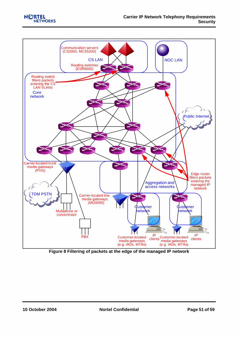
Carrier IP Network Telephony RequirementsSecurity
Figure 8 Filtering of packets at the edge of the managed IP network
Multiplexor orconcentrator
PBX
Carrier-located trunkmedia gateways
(PVG)
IPclients
Core network
Routing switches(ESR8600)
Communication servers(CS2000, MCS5200)
CS LAN
Carrier-located linemedia gateways
(MG9000)
Aggregation and access networks
Customer network
Customer network
Customer-locatedmedia gateways
(e.g. IADs, MTAs)
IPclients
NOC LAN
Customer-locatedmedia gateways
(e.g. IADs, MTAs)
Routing switch filters packets
entering the CS LAN VLANs
Edge router filters packets entering the managed IP
network
Public Internet
TDM PSTN
10 October 2004 Nortel Confidential Page 51 of 59

Carrier IP Network Telephony Requirements Security
5.4 Cryptographic ProtectionCryptographic separation of traffic uses protocols that provide authentication and encryption in the IP layer or above. Authentication and encryption provide the following checks on communications:
AuthenticationIntegrity guarantees that a message has not been not falsified in transit. Authenticity guarantees that a message has not been falsified in transit or generated by an untrusted source. Non-repudiability guarantees that a message has not been falsified in transit, generated by an untrusted source or falsified on arrival.
Encryption guarantees that a message has not been read in transit.
Authentication and encryption should be applied wherever these checks are desirable and available. They are most important for management streams, but are also relevant for signalling streams and media streams. They are usually applied outside the network, at the application level. The responsibilities of the managed IP network for them are limited to the following:
Using authentication and encryption itself where possible (e.g. by applying MD5 HMAC to authenticate routing protocol messages).
Preventing denial of service and denial of content attacks as far as possible (and, in particular, preventing modification or destruction of encrypted or authenticated packets).
Ensuring that traffic across the network is not subject to address modifications (e.g. by NAPT devices), which could invalidate authentication or encryption based on an address or on a key that incorporates an address.
Authentication and encryption are not available for all network elements. In particular, they are not available for certain third-party line media gateways. Theft of service and theft of content attacks may therefore still be feasible, which means that the network must continue to have essential responsibilities for:
Preventing, as far as possible, addresses from being “spoofed” (fabricated by network elements that do not own the addresses).
Preventing, as far as possible, packets from being read or modified by untrustworthy network elements.
5.5 User AuthorisationIn Nortel carrier telephony or multimedia over IP, user authorisation is primarily concerned with preventing unauthorised access to communication servers and other network elements. This unauthorised access might be intended to be used by either a service application or a management application. Access is secured during service registration for IP clients and management log-in; the responsibility of the managed IP network is mainly to carry the messages. Of course, access to the managed IP network routers and other network elements must also be secured.
Page 52 of 59 Nortel Confidential 10 October 2004

Carrier IP Network Telephony RequirementsSecurity
5.6 Security LoggingAll routers and other devices should maintain security logs of who does what to them. Audit logs should contain enough information to allow the creation of audit trails (finding the sequences of activities and events in the logs) and thereby help to achieve the following specific objectives:
Individual accountability.
Root cause analysis of security problems.
Trend detection.
5.7 Vulnerability AssessmentThe vast majority of network intrusions exploit known weaknesses in system design and configuration. Vulnerability assessment systems check which operating systems, protocols and services are in use on network nodes so that potential vulnerabilities known to be associated with particular software can be identified and minimised. They assess node and system vulnerability by means of scanning techniques based on protocols such as Internet Control Message Protocol (ICMP).
Vulnerability assessment systems have varying degrees of success. However, even partial success is useful, so comprehensive vulnerability assessment is recommended.
5.8 Intrusion DetectionIntrusion detection systems monitor patterns of activities and events to check whether the network is about to be attacked or whether weaknesses in the defences have been exploited. They typically look for known patterns of misuse or anomalous behaviour.
An intrusion detection system that has no application awareness can detect only patterns of misuse with rather simple signatures. Application awareness is required to detect such problems as an RTP stream continuing to flow after a call has ostensibly ended.
Intrusion detection systems that look for anomalous behaviour focus on protocol message sequences, volumes of different traffic types and network usage patterns. They can help to detect, for instance, unknown or disguised attacks intended to make buffers overflow.
Intrusion detection systems typically help to defend against attacks subverting management or control traffic rather than media or signalling traffic. They can most usefully be deployed near the network perimeter (for network-based intrusion detection) and on crucial servers (for host-based intrusion detection).
10 October 2004 Nortel Confidential Page 53 of 59

6 AddressingAt the network edge the managed IP network connects with various networks and network elements. These must use IP addressing strategies that conform with the standard outlined in section 6.1. Additional requirements and recommendations appropriate to these strategies are described in section 6.2.
The IP addressing strategies may nonetheless conflict. The technique for resolving these conflicts that is adopted by service providers and customers is explained in section 6.3. However, this technique itself creates difficulties that must be removed if service providers are to deploy telephony or multimedia over IP. The way of removing them introduced by Nortel is indicated in section 6.4.
6.1 Public and Private Addresses.Private IP addresses are used to increase the effective number of IP addresses that are available. (They thereby reduce the problem of the depletion of globally unique IP addresses and simplify network structuring and management.) Two networks can use the same private IP addresses, provided that there is no routing between them that uses these addresses. Instead, the networks must translate between their private addresses and public addresses that are externally accessible points of contact to the networks. Typically the translations are performed at the edges of the networks, which form separate ‘addressing domains’.
Here the term ‘public address’ does not necessarily signify a public internet address. It denotes an address that is accessible to certain external networks. The private addresses and the public addresses for a network constitute a private addressing domain and a public addressing domain respectively; the public addressing domain can support routing between different private addressing domains.
The Internet Assigned Numbers Authority (IANA) has reserved the following ranges of IP addresses for private addressing domains, as described in RFC 1918:
From 10.0.0.0 to 10.255.255.255 (10.0.0.0/8 prefix), yielding 224 or 16M IP addresses.
From 172.16.0.0 to 172.31.255.255 (172.16.0.0/12 prefix), yielding 220 or 1M IP addresses.
From 192.168.0.0 to 192.168.255.255 (192.168.0.0/16 prefix), yielding 216 or 64K IP addresses.
10 October 2004 Nortel Confidential Page 54 of 59

Carrier IP Network Telephony RequirementsAddressing
6.2 Implications at the Network EdgeThe addressing domains envisaged in Nortel Networks carrier telephony or multimedia over IP include the following:
The service provider end point addressing domain, containing the CS LAN and carrier-located media gateways. It is a private addressing domain.
Customer networks. Customer-located media gateways typically lie behind Network Address and Port Translation (NAPT) devices and firewalls for the customer networks. These networks constitute private addressing domains.
The managed IP network, lying between the service provider end point addressing domain and the customer networks. This supports communication between private addressing domains (which might be those of service providers or customers). It is regarded as a public addressing domain by these private addressing domains, but it is actually another private network belonging to the service provider, not a network open to everyone.
The public internet.
Nortel Networks imposes no rigid IP addressing rules; any IP addressing strategy can be adopted subject to the following basic requirements:
The service provider end point addressing domain can reach and be reached from the managed IP network addressing domain.
The managed IP network can reach and be reached from the private addressing domains of customers.
Some service providers may already have devised and deployed IP addressing strategies that they wish to retain; others will not have done so. Nortel Networks provides recommendations for IP addressing strategies for service providers that do not have their own rules already. In such cases Nortel Networks suggests the following:
Call processing elements in the CallP VLAN of the CS LAN can be addressed by:Subnetting the 172.16.0.0/12 subnet with a 19-bit mask.Subnetting each block with a 23-bit mask to address the CallP VLAN for a given CS2000.
OAM&P elements in the OAM&P VLAN of the CS LAN can be addressed by reserving a /26 public subnet.
If a NOC is not already present, its addressing can be based on reserving a /27 public subnet.
If out-of-band management is adopted (typically, to add extra reliability to network management) it can be based on:
Using the 192.168.0.0/16 subnet for out-of-band management.Resubnetting this subnet according to the number of elements that need to be managed and their physical location.
Media gateway addressing depends on the particular network to be deployed, but can be based on:
Using the 10.0.0.0/8 subnet.
10 October 2004 Nortel Confidential Page 55 of 59

Carrier IP Network Telephony Requirements Addressing
Resubnetting this subnet with a 9-bit subnet mask (255.128.0.0).Resubnetting the resulting subnets with a 15-bit mask.
6.3 Network Address and Port TranslationNetwork Address Translation (NAT) is a method of binding IP addresses in one addressing domain to IP addresses in another domain, enabling transparent routing to take place between end points belonging to different addressing domains. Network Address and Port Translation (NAPT) extends NAT by also translating transport identifiers such as UDP port numbers; it thereby allows several end points to share a public address and allows a large number of private addresses to consume a small number of public addresses. The public addresses may be assigned dynamically and translated as required to meet the changing demands of the private addressing domains.
Unidirectional NAPT allows end points in a private addressing domain to access end points in a public addressing domain. Because the addresses of end points in a private addressing domain are unique only within that addressing domain and may not be valid in the public addressing domain, NAPT does not advertise private addresses to the public addressing domain, but does let public addresses be used in the private addressing domain.
Bidirectional NAPT translates addresses and ports in both directions, in order to prevent address collisions between the private addressing domain and the public addressing domain. Collisions might arise, for example, if the private addressing domain has improperly numbered internal nodes using public addresses.
Figure 9 illustrates unidirectional NAPT and bidirectional NAPT.
Figure 9 Unidirectional and bidirectional NAPT
Address translation for unidirectional NAPT
Private addressing
domain end point address
A:a
The public addressing domain end point is visible to the private addressing domain network end point, but not the other way round
Public addressing
domain end point address
B:b
Source address translatedOutgoing packet
Destination address translated Incoming packet
DA B:b SA A:a
DA A:a SA B:b
NAPTdevice DA B:b SA X:x
DA X:x SA B:b
Address translation for bidirectional NAPT
Private addressing
domain end point address
A:a
Both end points are visible only to the bidirectional NAPT device and not to each other
Public addressing
domain end point address
B:b
Both addresses translatedOutgoing packet
Both addresses translated Incoming packet
DA Y:y SA A:a
DA A:a SA Y:y
NAPTdevice DA B:b SA X:x
DA X:x SA B:bbinding:A:a - X:xY:y - B:b
binding:A:a - X:x
Page 56 of 59 Nortel Confidential 10 October 2004

Carrier IP Network Telephony RequirementsAddressing
6.4 Media Transport ProxiesCustomer networks usually perform NAPT at the boundary with the managed IP network, typically using their access routers for this purpose. Signalling protocol messages may mention media end point addresses, so applying NAPT to media end point addresses can make telephony or multimedia over IP infeasible. (The problems with NAPT are described in RFC 3027.) Nortel Networks carrier telephony or multimedia over IP places no requirements on applications of NAPT to media end point addresses; in particular, customer networks (and indeed the managed IP network) can perform any form of NAPT any number of times.
For Nortel Networks carrier telephony or multimedia over IP, bidirectional NAPT is used to ensure that a customer network does not need to know public addresses allocated by the NAPT devices in another private addressing domain. This bidirectional NAPT is provided by a media transport proxy (a network element that terminates and re-originates the transport layer for media traffic). This has two specific capabilities:
It enables media streams to traverse NAPT devices and firewalls that control access to customer networks.
It can act as a firewall to control the entry of media streams into the private addressing domain that contains the CS LAN and carrier-located media gateways.
A media transport proxy (or ‘media proxy’ for brevity) is controlled by a communication server. It is inserted in a call when call processing on the communication server determines that a media stream satisfies one of the following conditions:
The media stream has end points in different addressing domains (as at least one of them lies behind a NAPT device).
The media stream crosses between the private addressing domain that contains the communication servers and carrier-located media gateways and a public addressing domain that is accessible to customers or is otherwise untrusted.
NAPT is then performed on the IP addresses and UDP ports specified in the source and destination fields of each incoming packet.
Media traffic for calls involving a media proxy does not pass directly between media gateways, so network engineering must consider the following:
Capacity is affected because packet flows routed through media proxies need extra bandwidth on the network segments containing the media proxies.
Performance is affected because packet flows routed through media proxies incur small additional delays.
Generally media proxies should be located as close as possible to the media gateways for which they are to provide proxy functionality. The following configurations are typical:
Media proxies located on the CS LAN.
Media proxies collocated with carrier-located gateways
Media proxies collocated with broadband remote access servers connected to customer-located gateways.
Figure 10 shows the configuration when a media proxy is located on the CS LAN.
10 October 2004 Nortel Confidential Page 57 of 59

Carrier IP Network Telephony Requirements Addressing
Figure 10 Use of a media proxy for calls involving NAPT
Multiplexor orconcentrator
PBX
Carrier-located trunkmedia gateways
(PVG)
IPclients
Core network
Routing switches(ESR8600)
Communication servers(CS2000, MCS5200)
CS LAN
Carrier-located linemedia gateways
(MG9000)Customer network
Customer network
Customer-locatedmedia gateways
(e.g. IADs, MTAs)
IPclients
NOC LAN
Customer-locatedmedia gateways
(e.g. IADs, MTAs)
Edge router possibly applies NAPT to some
packets
Access router probably applies
NAPT to all packets
Media proxy applies NAPT to
acceptable packets to or
from customer networks under
the control of the communication
server
Aggregation and access networks
Public Internet
TDM PSTN
Page 58 of 59 Nortel Confidential 10 October 2004

10 October 2004 Nortel Confidential Page 59 of 59
7 TimingTelephony or multimedia over IP needs the following forms of synchronisation:
Network clock synchronisation (to provide bit synchronisation for transmission paths), discussed in section 7.1.
Time of day synchronisation (to ensure consistency between time stamps in billing records, logs and reports generated by network elements), discussed in section 7.2.
7.1 Network Clock SynchronisationIn a TDM network, network clock synchronisation is required for all network elements because all transmission paths are synchronous. In an IP network, on the other hand, network clock synchronisation is required for most network elements, but only for those that terminate synchronous transmission paths. (The term ‘clock’ here denotes a frequency reference, not a time of day indicator.) For Nortel carrier telephony or multimedia over IP, these network elements are the signalling and media gateways with interfaces to the TDM network. If these network elements are not synchronised there can be buffer overruns or underruns and, in consequence, actual or apparent packet loss.
For signalling gateways and carrier-located media gateways, network clock synchronisation is required on TDM carriers in order to minimise slips. This requires an external clock source synchronised with the TDM PSTN. This source can be provided by a stratum 0 clock, such as a GPS reference system or a precision controlled oscillator. GPS can achieve synchronisation to within 100 µs.
7.2 Time of Day SynchronisationNetwork Time Protocol (NTP), as specified in RFC 1305, is the most widely used protocol for time of day synchronisation across a network. An NTP client queries NTP servers to obtain the network time, which it then uses to calibrate its time of day clock. Simple Network Time Protocol (SNTP), as specified in RFC 1769, is a simplified scheme for servers and clients that do not need the degree of accuracy provided by NTP.
For Nortel carrier telephony or multimedia over IP, NTP provision for components attached to the CS LAN does not directly involve the managed IP network. Instead, at least two NTP servers should be supported by the OAM&P VLAN of the CS LAN and all routers and gateways acting as NTP clients should use these as synchronisation sources. These two NTP servers should themselves be synchronised with three independent stratum 1 clocks.
NTP can be deployed on any reliable server platform, such as a suitable element manager platform. (Typically, network element configuration commands specify the NTP servers to be used, with the element managers as defaults.) NTP might allow synchronisation to within 10 ms if the NTP servers and clients have stable and symmetrical delays.