cartooino projects book - greenlab microfactory · 2018-07-25 · this cartooino projects book is a...
TRANSCRIPT

1
CARTOOINO
Projects
Book
2
Acknowledgement
Acknowledgement
This Cartooino Projects Book is a cartoon based adaptation of the Arduino Projects Book.
The Cartooino Project Book was developed by the GreenLab Microfactory for use for her
‘One Student One Arduino’ project. The essence of which is to create a more relatable
learning approach for the participants of the One Student One Arduino’ project.
Therefore, the GreenLab Microfactory would like to acknowledge Arduino LLC for their
selflessness and contribution to the body of knowledge by fortifying the open source
community with their products and projects.
In addition, the cartoon characters used in this project book were developed using the
online animation platform ToonDoo (http://www.toondoo.com/). Finally, GreenLab
Microfactory will also like to acknowledge that some of the content of this book were
derived and adapted from the online platform Tutorials point
(https://www.tutorialspoint.com/index.htm).
Disclaimer
This book was not created for commercial purposes, and the contents of the Cartooino
Projects Book are licensed under a Creative Commons Attribution-NonCommercial-
ShareAlike 3.0 License 2012 by GreenLab Microfactory. This means that you can copy,
reuse, adapt and build upon the text of this book non-commercially while attributing the
original work (but not in any way that suggests that we endorse you or your use of the
work) and only if the results are transmitted under the same Creative Commons license.
Full license terms: creativecommons.org/licenses/by-nc-sa/3.0/

3
Introduction

4
Introduction
5
Introduction
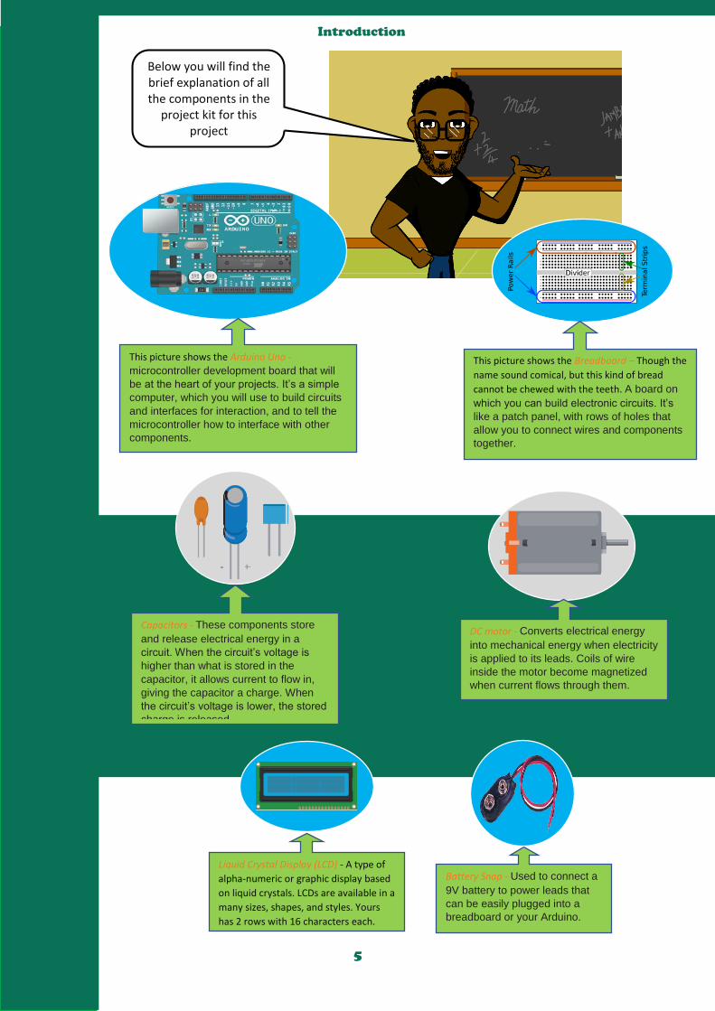
This picture shows the Arduino Uno -
microcontroller development board that will
be at the heart of your projects. It’s a simple
computer, which you will use to build circuits
and interfaces for interaction, and to tell the
microcontroller how to interface with other
components.
This picture shows the Breadboard – Though the
name sound comical, but this kind of bread
cannot be chewed with the teeth. A board on
which you can build electronic circuits. It’s
like a patch panel, with rows of holes that
allow you to connect wires and components
together.
Capacitors - These components store
and release electrical energy in a
circuit. When the circuit’s voltage is
higher than what is stored in the
capacitor, it allows current to flow in,
giving the capacitor a charge. When
the circuit’s voltage is lower, the stored
charge is released.
DC motor - Converts electrical energy
into mechanical energy when electricity
is applied to its leads. Coils of wire
inside the motor become magnetized
when current flows through them.
Battery Snap - Used to connect a
9V battery to power leads that
can be easily plugged into a
breadboard or your Arduino.
Liquid Crystal Display (LCD) - A type of
alpha-numeric or graphic display based
on liquid crystals. LCDs are available in a
many sizes, shapes, and styles. Yours
has 2 rows with 16 characters each.
Below you will find the brief explanation of all the components in the
project kit for this project
6
Introduction
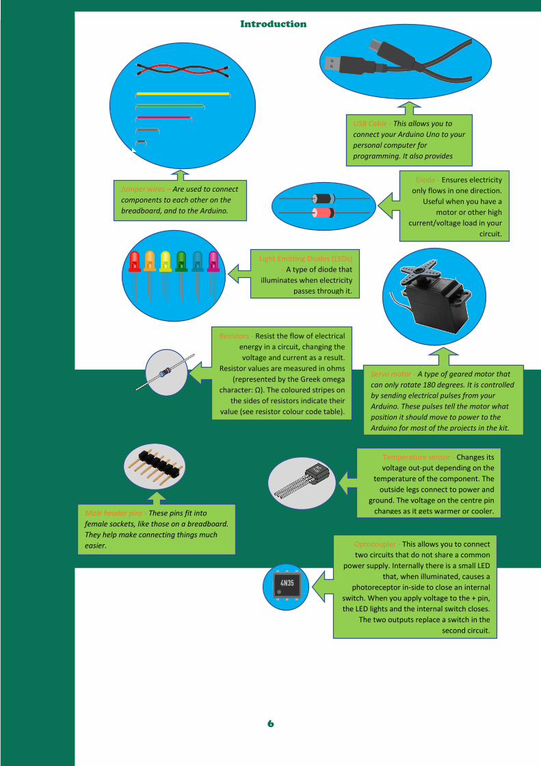
Jumper wires – Are used to connect
components to each other on the
breadboard, and to the Arduino.
USB Cable - This allows you to
connect your Arduino Uno to your
personal computer for
programming. It also provides
power to the Ar-duino for most of
the projects in the kit. Diode - Ensures electricity
only flows in one direction. Useful when you have a
motor or other high
current/voltage load in your
circuit.
Light Emitting Diodes (LEDs)
- A type of diode that
illuminates when electricity
passes through it.
Servo motor - A type of geared motor that
can only rotate 180 degrees. It is controlled
by sending electrical pulses from your
Arduino. These pulses tell the motor what
position it should move to power to the
Arduino for most of the projects in the kit.
Resistors - Resist the flow of electrical
energy in a circuit, changing the
voltage and current as a result.
Resistor values are measured in ohms
(represented by the Greek omega
character: Ω). The coloured stripes on
the sides of resistors indicate their
value (see resistor colour code table).
Male header pins - These pins fit into
female sockets, like those on a breadboard.
They help make connecting things much
easier.
Temperature sensor - Changes its
voltage out-put depending on the
temperature of the component. The
outside legs connect to power and
ground. The voltage on the centre pin
changes as it gets warmer or cooler.
Optocoupler - This allows you to connect
two circuits that do not share a common
power supply. Internally there is a small LED
that, when illuminated, causes a
photoreceptor in-side to close an internal
switch. When you apply voltage to the + pin,
the LED lights and the internal switch closes.
The two outputs replace a switch in the
second circuit.
7
Introduction
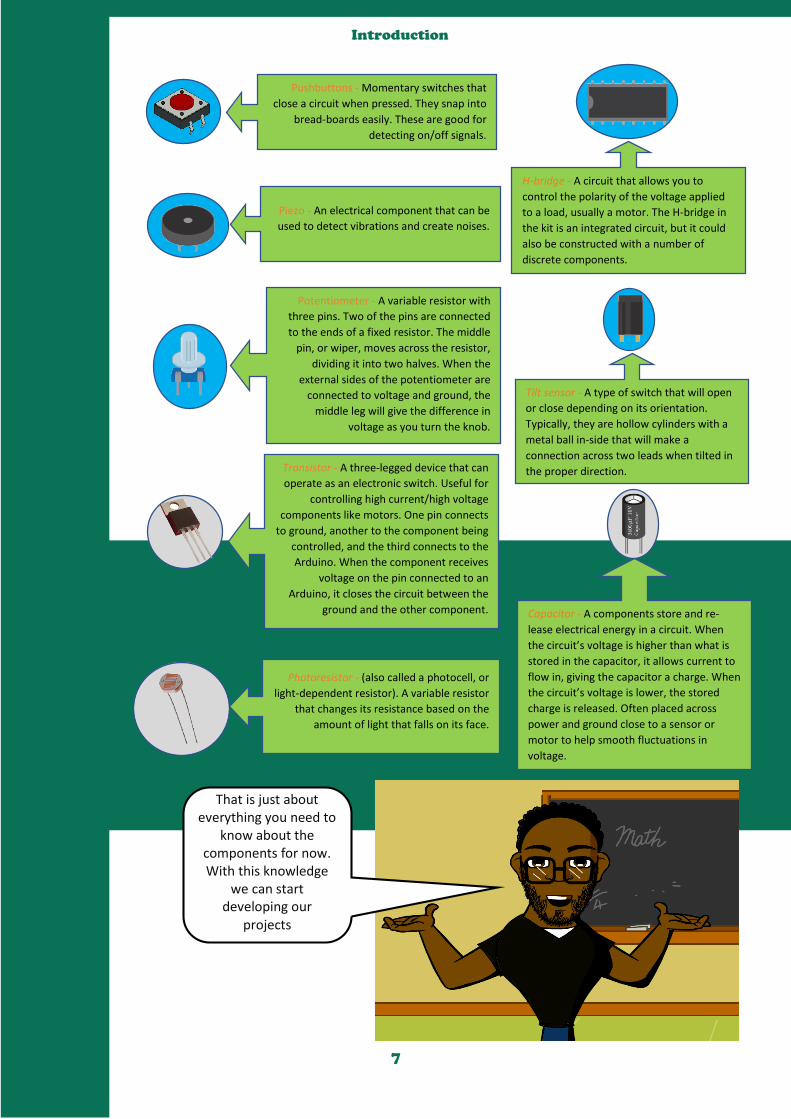
Pushbuttons - Momentary switches that
close a circuit when pressed. They snap into
bread-boards easily. These are good for
detecting on/off signals.
Piezo - An electrical component that can be
used to detect vibrations and create noises.
H-bridge - A circuit that allows you to
control the polarity of the voltage applied
to a load, usually a motor. The H-bridge in
the kit is an integrated circuit, but it could
also be constructed with a number of
discrete components.
Potentiometer - A variable resistor with
three pins. Two of the pins are connected
to the ends of a fixed resistor. The middle
pin, or wiper, moves across the resistor,
dividing it into two halves. When the
external sides of the potentiometer are
connected to voltage and ground, the
middle leg will give the difference in
voltage as you turn the knob.
Tilt sensor - A type of switch that will open
or close depending on its orientation.
Typically, they are hollow cylinders with a
metal ball in-side that will make a
connection across two leads when tilted in
the proper direction. Transistor - A three-legged device that can
operate as an electronic switch. Useful for
controlling high current/high voltage
components like motors. One pin connects
to ground, another to the component being
controlled, and the third connects to the
Arduino. When the component receives
voltage on the pin connected to an
Arduino, it closes the circuit between the
ground and the other component. Capacitor - A components store and re-
lease electrical energy in a circuit. When
the circuit’s voltage is higher than what is
stored in the capacitor, it allows current to
flow in, giving the capacitor a charge. When
the circuit’s voltage is lower, the stored
charge is released. Often placed across
power and ground close to a sensor or
motor to help smooth fluctuations in
voltage.
Photoresistor - (also called a photocell, or
light-dependent resistor). A variable resistor
that changes its resistance based on the
amount of light that falls on its face.
That is just about everything you need to
know about the components for now. With this knowledge
we can start developing our
projects
8
Introduction
Before we proceed
further, it is worthwhile to
know how to read a
resistor. Hope you still
remember what a resistor
is?
Below, an explanation on
how to read a resistor will
be given.
For your first
assignment, go through
your Arduino project kit
and perform the
following:
1. What types of
resistors are in your kit?
2. Calculate the values
of each type.
Source: https://electronics.stackexchange.com/questions/119/6-band-
resistors-which-way-should-the-bands-be-read
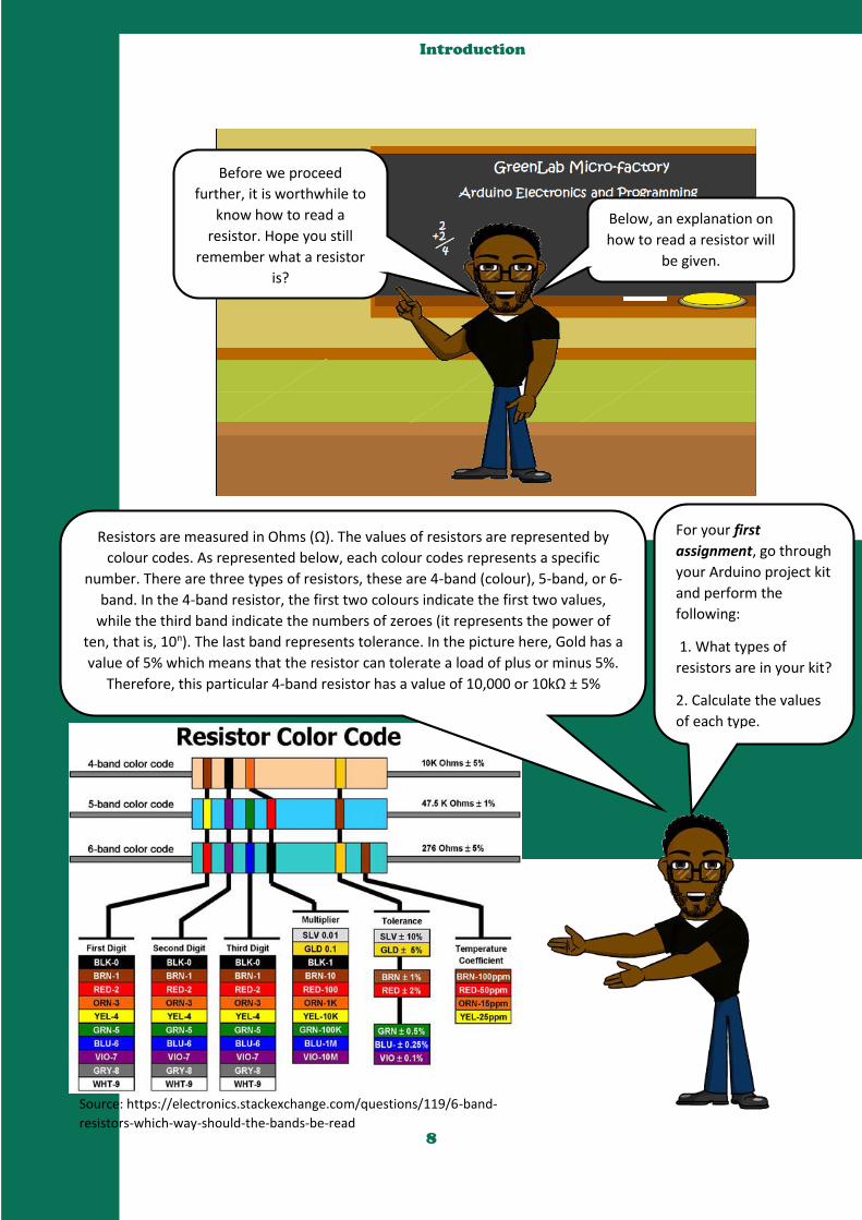
Resistors are measured in Ohms (Ω). The values of resistors are represented by
colour codes. As represented below, each colour codes represents a specific
number. There are three types of resistors, these are 4-band (colour), 5-band, or 6-
band. In the 4-band resistor, the first two colours indicate the first two values,
while the third band indicate the numbers of zeroes (it represents the power of
ten, that is, 10n). The last band represents tolerance. In the picture here, Gold has a
value of 5% which means that the resistor can tolerate a load of plus or minus 5%.
Therefore, this particular 4-band resistor has a value of 10,000 or 10kΩ ± 5%

9
Getting to know your tool –
Understanding the Arduino UNO
electronic Board
Power USB - Arduino board can be powered by using the USB cable from your
computer. All you need to do is connect the USB cable to the USB connection (1).
Power (Barrel Jack) Arduino boards can be powered directly from the AC mains power supply by connecting it to the Barrel Jack (2).
Voltage Regulator The function of the voltage regulator is to control the voltage given to the Arduino board and stabilize the DC voltages used by the processor and other elements.
Crystal Oscillator The crystal oscillator helps Arduino in dealing with time issues. How does Arduino calculate time? The answer is, by using the crystal oscillator. The number printed on top of the Arduino crystal is 16.000H9H. It tells us that the frequency is 16,000,000 Hertz or 16 MHz.
Arduino Reset You can reset your Arduino board, i.e., start your program from the beginning. You can reset the UNO board in two ways. First, by using the reset button (17) on the board. Second, you can connect an external reset button to the Arduino pin labelled RESET (5).
Pins (3.3, 5, GND, Vin) 3.3V (6) − Supply 3.3 output volt 5V (7) − Supply 5 output volt Most of the components used with Arduino board works fine with 3.3 volt and 5 volt.
I know you are eager to start
building your toys. But there are
few information you need to know
about the Arduino in your kit.
Source:https://www.tutorialspoint.com/arduino/arduino_board_description.htm
2
1
3
4
6, 7,
8, 9
5, 17
10
Getting to know your tool –
Understanding the Arduino UNO
electronic Board
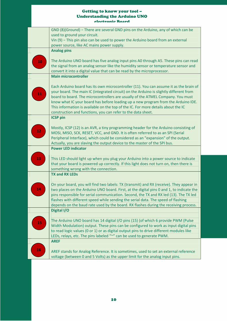
GND (8)(Ground) − There are several GND pins on the Arduino, any of which can be used to ground your circuit. Vin (9) − This pin also can be used to power the Arduino board from an external power source, like AC mains power supply.
Analog pins The Arduino UNO board has five analog input pins A0 through A5. These pins can read the signal from an analog sensor like the humidity sensor or temperature sensor and convert it into a digital value that can be read by the microprocessor.
Main microcontroller Each Arduino board has its own microcontroller (11). You can assume it as the brain of your board. The main IC (integrated circuit) on the Arduino is slightly different from board to board. The microcontrollers are usually of the ATMEL Company. You must know what IC your board has before loading up a new program from the Arduino IDE. This information is available on the top of the IC. For more details about the IC construction and functions, you can refer to the data sheet.
ICSP pin Mostly, ICSP (12) is an AVR, a tiny programming header for the Arduino consisting of MOSI, MISO, SCK, RESET, VCC, and GND. It is often referred to as an SPI (Serial Peripheral Interface), which could be considered as an "expansion" of the output. Actually, you are slaving the output device to the master of the SPI bus.
Power LED indicator This LED should light up when you plug your Arduino into a power source to indicate that your board is powered up correctly. If this light does not turn on, then there is something wrong with the connection.
TX and RX LEDs On your board, you will find two labels: TX (transmit) and RX (receive). They appear in two places on the Arduino UNO board. First, at the digital pins 0 and 1, to indicate the pins responsible for serial communication. Second, the TX and RX led (13). The TX led flashes with different speed while sending the serial data. The speed of flashing depends on the baud rate used by the board. RX flashes during the receiving process.
Digital I/O The Arduino UNO board has 14 digital I/O pins (15) (of which 6 provide PWM (Pulse Width Modulation) output. These pins can be configured to work as input digital pins to read logic values (0 or 1) or as digital output pins to drive different modules like LEDs, relays, etc. The pins labeled “~” can be used to generate PWM.
AREF AREF stands for Analog Reference. It is sometimes, used to set an external reference voltage (between 0 and 5 Volts) as the upper limit for the analog input pins.
10
11
12
13
14
15
16
11
Getting to know your tool – How to
Download, Install, and Setup the
Arduino IDE software
We are one step closer to the real
fun. In order to build your toy,
you first need to download,
install, and setup the Arduino IDE.
But Uncle!
What is an IDE?
Good question Ope! IDE means Integrated
Development Environment, and it is a software that
tells the Arduino board what you want to do. As a
developer you will be writing and testing software.
So the IDE allows you to write and test your code. An
IDE contains a code editor, a compiler or interpreter
and a debugger that the developer accesses through
a single graphical user interface (GUI).
I know you also would like to
know what I meant by code. A
source code is any collection
of computer instructions,
possibly with comments,
written using a human-
readable programming
language
Code! Oh! I now
Understand!
Thank you Uncle!
IDE!

12
Getting to know your tool – How to
Download, Install, and Setup the
Arduino IDE software
In this section you will be put
through on how to download,
install, and setup the Arduino IDE
after which the real fun begins.
To download the IDE, go to this link -
https://www.arduino.cc/en/Main/Software
. Please follow the steps and pictures below
to install and setup your IDE. Then we will
be ready to start building our prototypes.
Step 1: After your file download is complete, unzip
the file.

13
Getting to know your tool – How to
Download, Install, and Setup the
Arduino IDE software
Step 2: After the download the next step is to power up your Arduino
board.
The Arduino Uno automatically draw power from either, the USB connection
to the computer or an external power supply. To power up your Arduino,
connect the Arduino board to your computer using the USB cable. The green
power LED (labelled PWR) should glow.
Step 3: Now launch the Arduino IDE
After your Arduino IDE software is downloaded, you need to unzip the
folder. Inside the folder, you can find the application icon with an infinity
(∞) label (application.exe). Double-click the icon to start the IDE. As
shown in the diagram below.
Now it is time to open your first project.
Once the software starts, you have two
options – (1) Create a new project, or (2)
Open an existing project example.
The next pictures explains how to do these.
But before you can create your project, you
need to do step 5 and 6. So do those first
then create your project.

14
Getting to know your tool – How to
Download, Install, and Setup the
Arduino IDE software
Step 4.1: To create a new project, select File → New.
As shown in the picture below.
Step 4.2: To open an existing project example, select File → Example → Basics → Blink. Here,
you are selecting just one of the examples with the name Blink. Blink turns the LED on and off
with some time delay. If you like, you can select any other example from the list.
15
Getting to know your tool – How to
Download, Install, and Setup the
Arduino IDE software
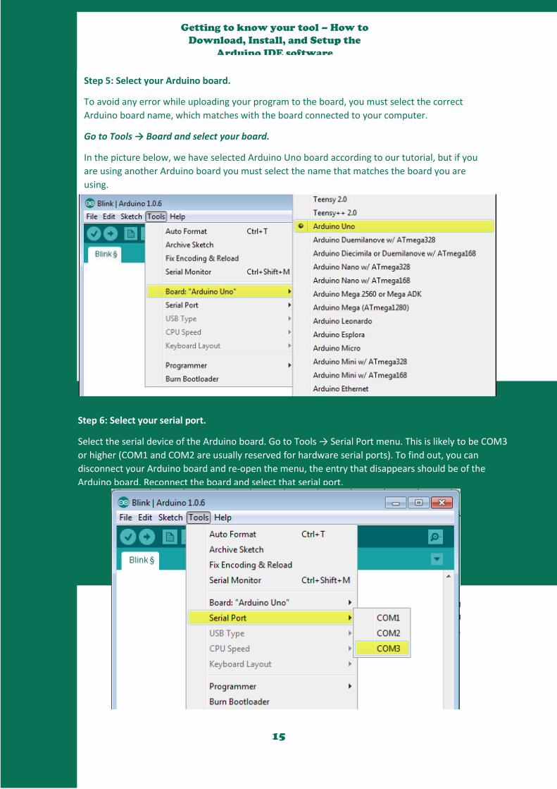
Step 5: Select your Arduino board.
To avoid any error while uploading your program to the board, you must select the correct
Arduino board name, which matches with the board connected to your computer.
Go to Tools → Board and select your board.
In the picture below, we have selected Arduino Uno board according to our tutorial, but if you
are using another Arduino board you must select the name that matches the board you are
using.
Step 6: Select your serial port.
Select the serial device of the Arduino board. Go to Tools → Serial Port menu. This is likely to be COM3
or higher (COM1 and COM2 are usually reserved for hardware serial ports). To find out, you can
disconnect your Arduino board and re-open the menu, the entry that disappears should be of the
Arduino board. Reconnect the board and select that serial port.
16
Getting to know your tool – How to
Download, Install, and Setup the
Arduino IDE software
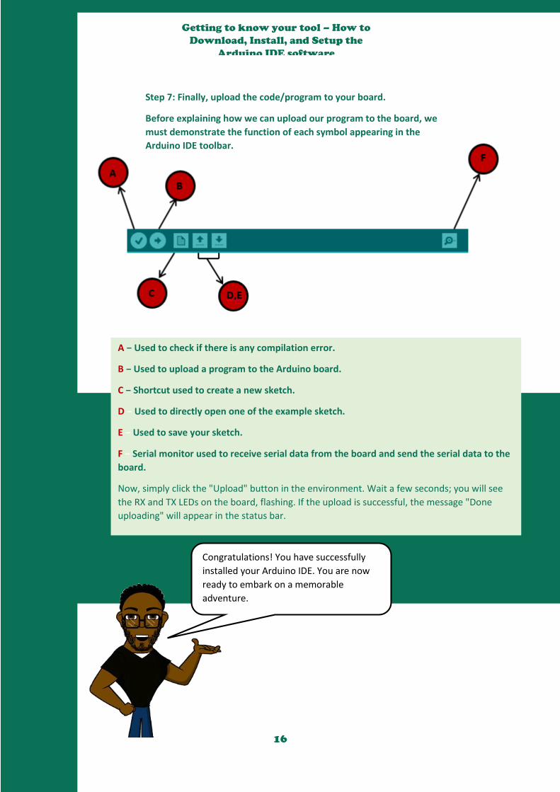
Step 7: Finally, upload the code/program to your board.
Before explaining how we can upload our program to the board, we
must demonstrate the function of each symbol appearing in the
Arduino IDE toolbar.
A − Used to check if there is any compilation error.
B − Used to upload a program to the Arduino board.
C − Shortcut used to create a new sketch.
D − Used to directly open one of the example sketch.
E − Used to save your sketch.
F − Serial monitor used to receive serial data from the board and send the serial data to the
board.
Now, simply click the "Upload" button in the environment. Wait a few seconds; you will see
the RX and TX LEDs on the board, flashing. If the upload is successful, the message "Done
uploading" will appear in the status bar.
Congratulations! You have successfully
installed your Arduino IDE. You are now
ready to embark on a memorable
adventure.

17
Project 01 – Build a Simple Circuit
Hello class, I am glad that you have made it this far. To officially
welcome you on the ‘One Student One Arduino’ project, you
will be given an opportunity to build a simple circuit.
To complete this project, you will need some switches, a LED,
and a 220Ω resistor. Lastly, you will need at least 30 minutes to
complete the project.
During this project, you will
discover some basic electrical
theory, and how to connect
components in series and parallel.
So if you are ready let’s start.
Electricity is a type of energy, much like heat, gravity, or light. Electrical energy flows through conductors,
like wire. You can convert electrical energy into other forms of energy to do something interesting, like
turn on a light or make some noise out of a speaker.
The components you might use to do this, like speakers or light bulbs, are electrical transducers.
Transducers change other types of energy into electrical energy and vice versa. Things that convert other
forms of energy into electrical energy are often called sensors, and things that convert electrical energy
into other forms of energy are sometimes called actuators. You will be building circuits to move electricity
through different components. Circuits are closed loops of wire with a power source (like a battery) and
something to do something useful with the energy, called a load.
In a circuit, electricity flows from a point of higher potential energy (usually referred to as power or +) to
a point of lower potential energy. Ground (often represented with a - or GND) is generally the point of
least potential energy in a circuit. In the circuits you are building, electricity only flows in one direction.
This type of circuit is called direct current, or DC. In alternating current (AC) circuits electricity changes its
direction 50 or 60 times a second (depending on where you live). This is the type of electricity that comes
from a wall socket.
There are a few terms you should be familiar with when working with electrical circuits. Current (measured
in amperes, or amps; with the A symbol) is the amount of electrical charge flowing past a specific point in
your circuit. Voltage (measured in volts; with the V symbol) is the difference in energy between one point
in a circuit and another. And finally, resistance (measured in ohms; with the Ω symbol) is how much a
component resists the flow of electrical energy.
The Basic Electrical Theory

18
Project 01 – Build a Simple Circuit
There are few things you need to
know about a circuit. These points
will be presented in the box below.
There needs to be a complete path from the energy source (power) to the
point of least energy (ground) to make a circuit. If there’s no path for the
energy to travel, the circuit won’t work.
All the electrical energy gets used up in a circuit by the components in it.
Each component converts some of the energy into another form of energy.
In any circuit, all of the voltage is converted to another form of energy (light,
heat, sound, etc.).
The flow of current at a specific point in a circuit will always be the same
coming in and going out.
Electrical current will seek the path of least resistance to ground. Given two
possible paths, more of the electrical current will go down the path with less
resistance. If you have a connection that connects power and ground
together with no resistance, you will cause a short circuit, and the current
will try to follow that path. In a short circuit, the power source and wires
convert the electrical energy into light and heat, usually as sparks or an
explosion. If you’ve ever shorted a battery and seen sparks, you know how
dangerous a short circuit can be.
The diagram below shows a simple circuit made
from three jumper cables, a 220Ω resistor, and a
LED. Please go to the introduction section to get
more information about each of these components.
Don’t forget that the long leg of the LED is the
positive side (+) called anode, while the short leg is
the negative (-) side called cathode.

19
Project 01 – Build a Simple Circuit
One major warning
for you to note. Always unplug
your Arduino from the power
source before building the
circuit.
Connect the jumper cables, push button, resistor, and LED
(with a jumper wire connect the long leg of the LED to the
anode, and the short leg of the LED to ground) from the
Arduino board to the breadboard as shown in this picture.
Once you are done connecting them, now connect your
Arduino to the computer using the USB cable. Now press the
pushbutton to switch on the LED. If the LED lights up then you
have successfully built your first circuit. Congratulations!

20
Project 01 – Build a Simple Circuit
After successfully building your
first circuit. Now you will learn the
differences between the two types
of circuit you can build. Which are
series circuit and a parallel circuit.
Once again do not forget to unplug
the Arduino board from the computer before
making any changes to the breadboard.
Series circuit
Components in SERIES come one after another
To build this remove your power source, add a switch next to
the one already on your breadboard. Wire them together in
series as shown in the diagram on the right hand side.
Connect the anode (long leg) up the LED to the second
switch. Connect the LED cathode to ground. Power up the
Arduino again: now to turn on the LED, you need to press
both switches. Since these are in series, they both need to be
closed for the circuit to be completed.

21
Project 01 – Build a Simple Circuit
Parallel circuit
Components in PARALLEL run side by side
To wire up switches in parallel, keep the switches
and LED where they are, but remove the
connection between the two switches. Wire both
switches to the resistor. Attach the other end of
both switches to the LED, as shown in the
diagram on the right hand side. Now when you
press any of the buttons, the circuit is completed
and the light turns on.
We have now gotten to the end of our first project. During this
project, you have learned about the basic electrical theory, that is,
properties of voltage, current, and resistance while building a very
simple circuit on a breadboard. With basic components like LED,
resistor and switches, you have created the simplest interactive
system where the user presses the button in order to switch on the
light.
These fundamental knowledge of working with electronics will be
built upon in the following projects.
In the next project, you will be building a spaceship interface so
you can explore and discover the galaxy. See you then.
22
Project 02 – Spaceship Interface
Uncle! At the end of the
last class you said we will
build a spaceship
interface today. But what
is a spaceship?
A spaceship is a craft, vehicle,
vessel or machine designed to
take humans or things deep into
the sky. Just like the one here.
So in today’s class, you
will learn how to build an
interface to send signals
deep into the galaxy.
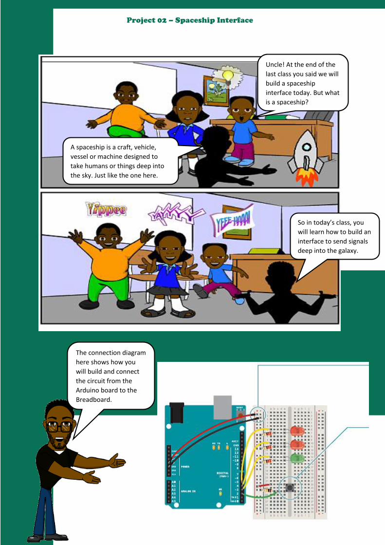
The connection diagram
here shows how you
will build and connect
the circuit from the
Arduino board to the
Breadboard.
23
Project 02 – Spaceship Interface
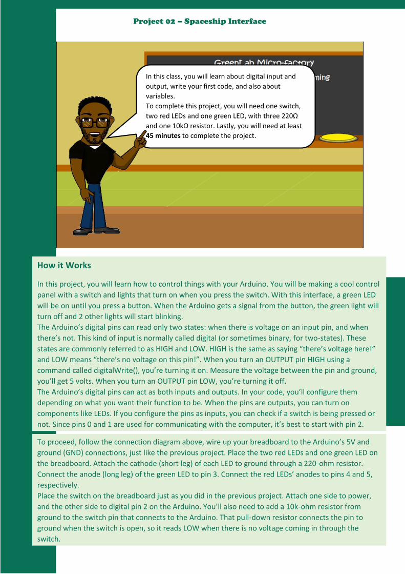
In this class, you will learn about digital input and
output, write your first code, and also about
variables.
To complete this project, you will need one switch,
two red LEDs and one green LED, with three 220Ω
and one 10kΩ resistor. Lastly, you will need at least
45 minutes to complete the project.
How it Works
In this project, you will learn how to control things with your Arduino. You will be making a cool control
panel with a switch and lights that turn on when you press the switch. With this interface, a green LED
will be on until you press a button. When the Arduino gets a signal from the button, the green light will
turn off and 2 other lights will start blinking.
The Arduino’s digital pins can read only two states: when there is voltage on an input pin, and when
there’s not. This kind of input is normally called digital (or sometimes binary, for two-states). These
states are commonly referred to as HIGH and LOW. HIGH is the same as saying “there’s voltage here!”
and LOW means “there’s no voltage on this pin!”. When you turn an OUTPUT pin HIGH using a
command called digitalWrite(), you’re turning it on. Measure the voltage between the pin and ground,
you’ll get 5 volts. When you turn an OUTPUT pin LOW, you’re turning it off.
The Arduino’s digital pins can act as both inputs and outputs. In your code, you’ll configure them
depending on what you want their function to be. When the pins are outputs, you can turn on
components like LEDs. If you configure the pins as inputs, you can check if a switch is being pressed or
not. Since pins 0 and 1 are used for communicating with the computer, it’s best to start with pin 2.
To proceed, follow the connection diagram above, wire up your breadboard to the Arduino’s 5V and
ground (GND) connections, just like the previous project. Place the two red LEDs and one green LED on
the breadboard. Attach the cathode (short leg) of each LED to ground through a 220-ohm resistor.
Connect the anode (long leg) of the green LED to pin 3. Connect the red LEDs’ anodes to pins 4 and 5,
respectively.
Place the switch on the breadboard just as you did in the previous project. Attach one side to power,
and the other side to digital pin 2 on the Arduino. You’ll also need to add a 10k-ohm resistor from
ground to the switch pin that connects to the Arduino. That pull-down resistor connects the pin to
ground when the switch is open, so it reads LOW when there is no voltage coming in through the
switch.

24
Project 02 – Spaceship Interface
For you to be able to control things with your
Arduino you will need to write some codes to
instruct the Arduino. Below, we will be
talking about how to write the ‘Codes’.
Understanding Arduino Code
The source code in Arduino is called “Sketch”.
Arduino programs can be divided in three main parts: Structure, Values
(variables and constants), and Functions. In this tutorial, we will learn
about the Arduino software program, step by step, and how we can write
the program without any syntax or compilation error.
Let us start with the Structure. Software structure consist of two main
functions −
Setup( ) function
Loop( ) function
The setup() function is called when a sketch starts. Use it to initialize the variables, pin modes, start
using libraries, etc. The setup function will only run once, after each power up or reset of the Arduino
board. This is where you configure the digital pins to be either inputs or outputs using a function named
pinMode(). The pins connected to LEDs will be OUTPUTs and the switch pin will be an INPUT.
The loop() function does precisely what its name suggests, and loops continuously, allowing your
program to change and respond. Use it to actively control the Arduino board. The loop() is where you’ll
check for voltage on the inputs, and turn outputs on and off. To check the voltage level on a digital
input, you use the function digitalRead() that checks the chosen pin for voltage. To know what pin to
check, digitalRead() expects an argument.
Arguments are information that you pass to functions, telling them how they should do their job. For
example, digitalRead() needs one argument: what pin to check. In your program, digitalRead() is going to
check the state of pin 2 and store the value in the switchState variable.
If there’s voltage on the pin when digitalRead() is called, the switchState variable will get the value HIGH
(or 1). If there is no voltage on the pin, switchState will get the value LOW (or 0).
Curly brackets
Any code you write inside
the curly brackets will be
executed when the function
is called.

25
Project 02 – Spaceship Interface
S
int switchState = 0; // this is a comment. Comments are used to explain a code
void setup()
// put your setup code here, to run once:
pinMode(3,OUTPUT);
pinMode(4,OUTPUT);
pinMode(5,OUTPUT);
pinMode(2,INPUT);
void loop()
// put your main code here, to run repeatedly:
switchState = digitalRead(2);
if (switchState == LOW) // the button is not pressed
digitalWrite(3, HIGH); // green light
digitalWrite(4, LOW); // red light
digitalWrite(5, LOW); // red light
else // the button is pressed
digitalWrite(3, LOW);
digitalWrite(4, LOW);
digitalWrite(5, HIGH);
delay(250); // waits for a quarter second
digitalWrite(4, HIGH);
digitalWrite(5, LOW);
delay(250);
Case sensitivity
Pay attention to the case
sensitivity in your code. For
example, pinMode is the name
of a command, but pinmode
will produce an error.
Comments
If you ever want to include natural
language in your program, you can
leave a comment. Comments are
notes you leave for yourself that the
computer ignores. To write a
comment, add two slashes //
The computer will ignore anything on
the line after those slashes.
Enter the Code below on your Arduino IDE to build
and control the spaceship interface
26
Project 02 – Spaceship Interface
If Statement
In the code above, you used the word if to check the state of something (namely, the switch
position). An if() statement in programming compares two things, and determines whether the
comparison is true or false. Then it performs actions you tell it to do. When comparing two
things in programming, you use two equal signs ==. If you use only one sign, you will be setting
a value instead of comparing it.
Spaceship Interface Code
digitalWrite() is the command that allows you to send 5V or 0V to an output pin. digitalWrite()
takes two arguments: what pin to control, and what value to set that pin, HIGH or LOW. If you
want to turn the red LEDs on and the green LED off inside your if() statement, your code would
look like this .
You’ve told the Arduino what to do when the switch is open. Now define what happens when
the switch is closed. The if() statement has an optional else component that allows for
something to happen if the original condition is not met. In this case, since you checked to see
if the switch was LOW, write code for the HIGH condition after the else statement.
To get the red LEDs to blink when the button is pressed, you’ll need to turn the lights off and
on in the else statement you just wrote. To do this, change the code to look like this.
After setting the LEDs to a certain state, you’ll want the Arduino to pause for a moment before
changing them back. If you don’t wait, the lights will go back and forth so fast that it will
appear as if they are just a little dim, not on and off. This is because the Arduino goes through
its loop() thousands of times each second, and the LED will be turned on and off quicker than
we can perceive. The delay() function lets you stop the Arduino from executing anything for a
period of time. delay() takes an argument that determines the number of milliseconds before it
executes the next set of code. There are 1000 milliseconds in one second. delay(250) will pause
for a quarter second.
Once your Arduino is programmed, you should see the green light turn on. When you press the
switch, the red lights will start flashing, and the green light will turn off. Try changing the time
of the two delay() functions; notice what happens to the lights and how the response of the
system changes depending on the speed of the flashing. When you call a delay() in your
program, it stops all other functionality. No sensor readings will happen until that time period
has passed. While delays are often useful, when designing your own projects make sure they
are not unnecessarily interfering with your interface.
27
Project 02 – Spaceship Interface
Uncle! What is a
function? What is
‘int’, and I also
need more
information
about variables.
What is a
Function!
We have now gotten to the end of our second project.
In this project, you created your first Arduino program
to control the behaviour of some LEDs based on a
switch. You have used variables, an if()...else
statement, and functions to read the state of an input
and control outputs.
Good question! In
the next class I will
explain everything
better to you.

28
Project 03 – Understanding the
Program Structure
Hello Everyone! Welcome back to our Arduino
class. In today’s class, you will learn more about
functions, variables, if-statements, loops, and other
concepts used in Arduino.
Again, you will use the analogWrite() function to
make a LED fade. To complete this simple project,
you will need one LED, one 220Ω resistor, and
some jumper wires. Lastly, you will need at least 60
minutes to complete the project.
Uncle! Why do
we need to
know all these? You see Ope, without all
these information you
will not be able to build
your toys and other
prototypes properly.

29
Project 03 – Understanding the
Program Structure
Without further ado, let’s carry on with
our explanation. Please be informed
that only brief information with regards
to the structure will be provided.
void
The void keyword is used only in function declarations. It indicates that the function is expected to
return no information to the function from which it was called.
Example
Void Loop ( )
// rest of the code
Boolean
A Boolean holds one of two values, true or false. Each Boolean variable occupies one byte of
memory.
Example
boolean val = false ; // declaration of variable with type boolean and initialize it with false
boolean state = true ; // declaration of variable with type boolean and initialize it with true
Data types
Data types are used for declaring variables or functions of different
types. It determines how much space it occupies in the storage and
how the bit pattern stored is interpreted.
The following are all the data types that you will use during Arduino
programming.
1). void 2). Boolean 3). char 4). Unsigned char
5). Byte 6). int 7). word 8). Unsigned int
9). long 10). Unsigned long 11). String-object
12). short 13). float 14). double 15). array
16). String-char array

30
Project 03 – Understanding the
Program Structure
Char
A data type that takes up one byte of memory that stores a character value. Character literals are
written in single quotes like this: 'A' and for multiple characters, strings use double quotes: "ABC".
However, characters are stored as numbers. You can see the specific encoding in the ASCII chart.
This means that it is possible to do arithmetic operations on characters, in which the ASCII value of
the character is used. For example, 'A' + 1 has the value 66, since the ASCII value of the capital letter
A is 65.
Example
Char chr_a = ‘a’ ;//declaration of variable with type char and initialize it with character a
Char chr_c = 97 ;//declaration of variable with type char and initialize it with character
Unsigned char
Unsigned char is an unsigned data type that occupies one byte of memory. The unsigned char data
type encodes numbers from 0 to 255.
Example
Unsigned Char chr_y = 121 ; // declaration of variable with type Unsigned char and initialize it with
character y
byte
A byte stores an 8-bit unsigned number, from 0 to 255.
Example
byte m = 25 ;//declaration of variable with type byte and initialize it with 25
int
Integers are the primary data-type for number storage. int stores a 16-bit (2-byte) value. This yields
a range of -32,768 to 32,767 (minimum value of -2^15 and a maximum value of (2^15) - 1).
The int size varies from board to board. On the Arduino Due, for example, an int stores a 32-bit (4-
byte) value. This yields a range of -2,147,483,648 to 2,147,483,647 (minimum value of -2^31 and a
maximum value of (2^31) - 1).
Example
int counter = 32 ;// declaration of variable with type int and initialize it with 32

31
Project 03 – Understanding the
Program Structure
Unsigned int
Unsigned ints (unsigned integers) are the same as int in the way that they store a 2 byte value.
Instead of storing negative numbers, however, they only store positive values, yielding a useful
range of 0 to 65,535 (2^16) - 1). The Due stores a 4 byte (32-bit) value, ranging from 0 to
4,294,967,295 (2^32 - 1).
Example
Unsigned int counter = 60 ; // declaration of variable with
type unsigned int and initialize it with 60
Word
On the Uno and other ATMEGA based boards, a word stores a 16-bit unsigned number. On the Due
and Zero, it stores a 32-bit unsigned number.
Example
word w = 1000 ;//declaration of variable with type word and initialize it with 1000
Long
Long variables are extended size variables for number storage, and store 32 bits (4 bytes), from -
2,147,483,648 to 2,147,483,647.
Example
Long velocity = 102346 ;//declaration of variable with type Long and initialize it with 102346
Unsigned long
Unsigned long variables are extended size variables for number storage and store 32 bits (4 bytes).
Unlike standard longs, unsigned longs will not store negative numbers, making their range from 0 to
4,294,967,295 (2^32 - 1).
Example
Unsigned Long velocity = 101006 ;// declaration of variable with
type Unsigned Long and initialize it with 101006
short
A short is a 16-bit data-type. On all Arduinos (ATMega and ARM based), a short stores a 16-bit (2-
byte) value. This yields a range of -32,768 to 32,767 (minimum value of -2^15 and a maximum value
of (2^15) - 1).
Example
short val = 13 ;//declaration of variable with type short and initialize it with 13
32
Project 03 – Understanding the
Program Structure
float
Data type for floating-point number is a number that has a decimal point. Floating-point numbers
are often used to approximate the analog and continuous values because they have greater
resolution than integers.
Floating-point numbers can be as large as 3.4028235E+38 and as low as -3.4028235E+38. They are
stored as 32 bits (4 bytes) of information.
Example
float num = 1.352;//declaration of variable with type float and initialize it with 1.352
double
On the Uno and other ATMEGA based boards, Double precision floating-point number occupies four
bytes. That is, the double implementation is exactly the same as the float, with no gain in precision.
On the Arduino Due, doubles have 8-byte (64 bit) precision.
Example
double num = 45.352 ;// declaration of variable with type double and initialize it with 45.
Now that you have learnt about the different types
of data types, next you will be learning about
variables. But before you proceed further, make
sure you spend more time learning the data type
by heart. That will eventually make you a real
Arduino genius you aspire to be.
33
Project 03 – Understanding the
Program Structure
What is Variable Scope?
Variables in Arduino has a property called scope. A scope is a region of the program and there are three
places where variables can be declared. They are −
Inside a function or a block, which is called local variables.
In the definition of function parameters, which is called formal parameters.
Outside of all functions, which is called global variables.
Local Variables
Variables that are declared inside a function or block are local variables. They can be used only by the
statements that are inside that function or block of code. Local variables are not known to function outside
their own. Following is the example using local variables −
Void setup ()
Void loop ()
int x , y ;
int z ; Local variable declaration
x = 0;
y = 0; actual initialization
z = 10;
Global Variables
Global variables are defined outside of all the functions, usually at the top of the program. The global
variables will hold their value throughout the life-time of your program.
A global variable can be accessed by any function. That is, a global variable is available for use throughout
your entire program after its declaration.
The following example uses global and local variables −
int T , S ;
float c = 0 ; Global variable declaration
Void setup ()
Void loop ()
int x , y ;
int z ; Local variable declaration
x = 0;
y = 0; actual initialization
z = 10;

34
Project 03 – Understanding the
Program Structure
Arithmetic Operators
Assume variable A holds 10 and variable B holds 20 then −
Example
void loop ()
int a = 9,b = 4,c;
c = a + b;
c = a - b;
c = a * b;
c = a / b;
c = a % b;
Result
a + b = 13
a - b = 5
a * b = 36
a / b = 2
Remainder when a divided by b = 1
Operator name Operator
simple
Description Example
assignment
operator =
Stores the value to the right of the equal sign in
the variable to the left of the equal sign. A = B
addition + Adds two operands A + B will
give 30
subtraction - Subtracts second operand from the first A - B will
give -10
multiplication * Multiply both operands A * B will
give 200
division / Divide numerator by denominator B / A will
give 2
modulo % Modulus Operator and remainder of after an
integer division
B % A will
give 0
Comparison Operators
Assume variable A holds 10 and variable B holds 20 then −
Show Example
Operators
An operator is a symbol that tells the compiler to perform specific mathematical or logical functions. The
following are the types of operators:
35
Project 03 – Understanding the
Program Structure
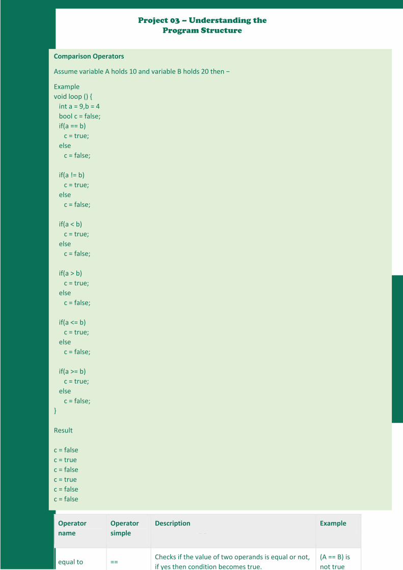
Comparison Operators
Assume variable A holds 10 and variable B holds 20 then −
Example
void loop ()
int a = 9,b = 4
bool c = false;
if(a == b)
c = true;
else
c = false;
if(a != b)
c = true;
else
c = false;
if(a < b)
c = true;
else
c = false;
if(a > b)
c = true;
else
c = false;
if(a <= b)
c = true;
else
c = false;
if(a >= b)
c = true;
else
c = false;
Result
c = false
c = true
c = false
c = true
c = false
c = false
Operator
name
Operator
simple
Description Example
equal to == Checks if the value of two operands is equal or not,
if yes then condition becomes true.
(A == B) is
not true
36
Project 03 – Understanding the
Program Structure
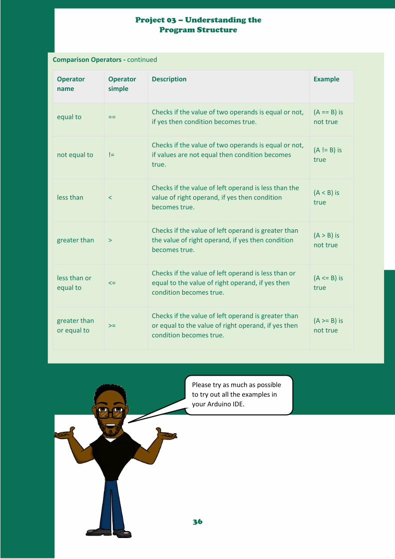
Comparison Operators - continued
Operator
name
Operator
simple
Description Example
equal to == Checks if the value of two operands is equal or not,
if yes then condition becomes true.
(A == B) is
not true
not equal to !=
Checks if the value of two operands is equal or not,
if values are not equal then condition becomes
true.
(A != B) is
true
less than <
Checks if the value of left operand is less than the
value of right operand, if yes then condition
becomes true.
(A < B) is
true
greater than >
Checks if the value of left operand is greater than
the value of right operand, if yes then condition
becomes true.
(A > B) is
not true
less than or
equal to <=
Checks if the value of left operand is less than or
equal to the value of right operand, if yes then
condition becomes true.
(A <= B) is
true
greater than
or equal to >=
Checks if the value of left operand is greater than
or equal to the value of right operand, if yes then
condition becomes true.
(A >= B) is
not true
Please try as much as possible
to try out all the examples in
your Arduino IDE.

37
Project 03 – Understanding the
Program Structure
Boolean Operators
Assume variable A holds 10 and variable B holds 20 then −
Operator
name
Operator
simple
Description Example
and && Called Logical AND operator. If both the operands are
non-zero then then condition becomes true.
(A && B) is
true
or || Called Logical OR Operator. If any of the two operands
is non-zero then then condition becomes true.
(A || B) is
true
not !
Called Logical NOT Operator. Use to reverses the logical
state of its operand. If a condition is true then Logical
NOT operator will make false.
!(A && B)
is false
Example
void loop ()
int a = 9,b = 4
bool c = false;
if((a > b)&& (b < a))
c = true;
else
c = false;
if((a == b)|| (b < a))
c = true;
else
c = false;
if( !(a == b)&& (b < a))
c = true;
else
c = false;
Result
c = true
c = true
c = true
38
Project 03 – Understanding the
Program Structure
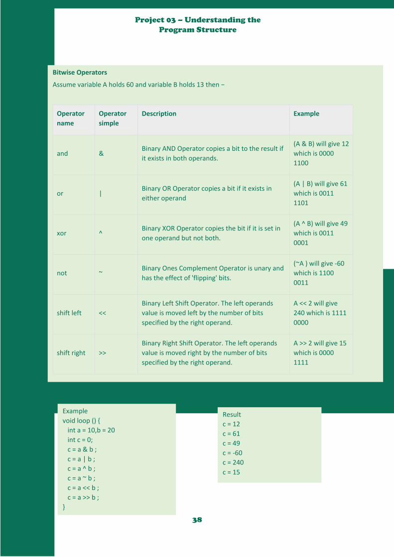
Bitwise Operators
Assume variable A holds 60 and variable B holds 13 then −
Operator
name
Operator
simple
Description Example
and & Binary AND Operator copies a bit to the result if
it exists in both operands.
(A & B) will give 12
which is 0000
1100
or | Binary OR Operator copies a bit if it exists in
either operand
(A | B) will give 61
which is 0011
1101
xor ^ Binary XOR Operator copies the bit if it is set in
one operand but not both.
(A ^ B) will give 49
which is 0011
0001
not ~ Binary Ones Complement Operator is unary and
has the effect of 'flipping' bits.
(~A ) will give -60
which is 1100
0011
shift left <<
Binary Left Shift Operator. The left operands
value is moved left by the number of bits
specified by the right operand.
A << 2 will give
240 which is 1111
0000
shift right >>
Binary Right Shift Operator. The left operands
value is moved right by the number of bits
specified by the right operand.
A >> 2 will give 15
which is 0000
1111
Example
void loop ()
int a = 10,b = 20
int c = 0;
c = a & b ;
c = a | b ;
c = a ^ b ;
c = a ~ b ;
c = a << b ;
c = a >> b ;
Result
c = 12
c = 61
c = 49
c = -60
c = 240
c = 15
39
Project 03 – Understanding the
Program Structure
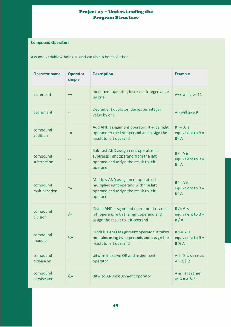
Compound Operators
Assume variable A holds 10 and variable B holds 20 then −
Operator name Operator
simple
Description Example
increment ++ Increment operator, increases integer value
by one A++ will give 11
decrement -- Decrement operator, decreases integer
value by one A-- will give 9
compound
addition +=
Add AND assignment operator. It adds right
operand to the left operand and assign the
result to left operand
B += A is
equivalent to B =
B+ A
compound
subtraction -=
Subtract AND assignment operator. It
subtracts right operand from the left
operand and assign the result to left
operand
B -= A is
equivalent to B =
B - A
compound
multiplication *=
Multiply AND assignment operator. It
multiplies right operand with the left
operand and assign the result to left
operand
B*= A is
equivalent to B =
B* A
compound
division /=
Divide AND assignment operator. It divides
left operand with the right operand and
assign the result to left operand
B /= A is
equivalent to B =
B / A
compound
modulo %=
Modulus AND assignment operator. It takes
modulus using two operands and assign the
result to left operand
B %= A is
equivalent to B =
B % A
compound
bitwise or |=
bitwise inclusive OR and assignment
operator
A |= 2 is same as
A = A | 2
compound
bitwise and &= Bitwise AND assignment operator
A &= 2 is same
as A = A & 2

40
Project 03 – Understanding the
Program Structure
Example
void loop ()
int a = 10,b = 20
int c = 0;
a++;
a--;
b += a;
b -= a;
b *= a;
b /= a;
a %= b;
a |= b;
a &= b;
Result
a = 11
a = 9
b = 30
b = 10
b = 200
b = 2
a = 0
a = 61
a = 12
Next, you will be learning more
about the control statements
which are ‘if-else’ and switch
case statements. As shown in
the picture here, if the condition
is true then the conditional code
is executed, else it is not
executed.
41
Project 03 – Understanding the
Program Structure
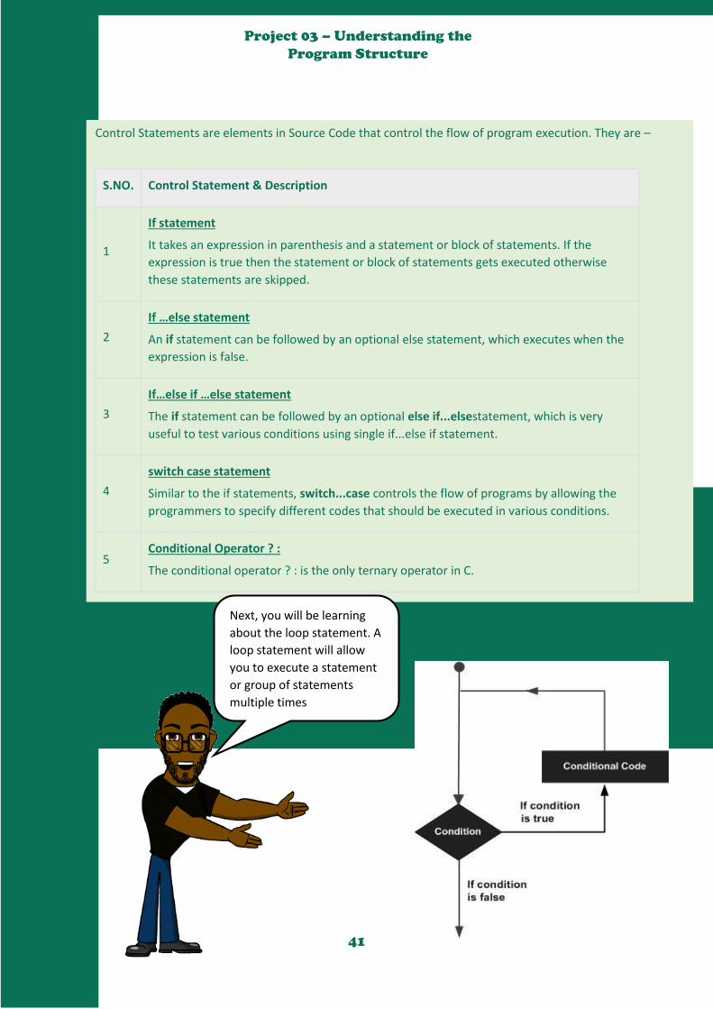
Control Statements are elements in Source Code that control the flow of program execution. They are –
S.NO. Control Statement & Description
1
If statement
It takes an expression in parenthesis and a statement or block of statements. If the
expression is true then the statement or block of statements gets executed otherwise
these statements are skipped.
2
If …else statement
An if statement can be followed by an optional else statement, which executes when the
expression is false.
3
If…else if …else statement
The if statement can be followed by an optional else if...elsestatement, which is very
useful to test various conditions using single if...else if statement.
4
switch case statement
Similar to the if statements, switch...case controls the flow of programs by allowing the
programmers to specify different codes that should be executed in various conditions.
5 Conditional Operator ? :
The conditional operator ? : is the only ternary operator in C.
Next, you will be learning
about the loop statement. A
loop statement will allow
you to execute a statement
or group of statements
multiple times
42
Project 03 – Understanding the
Program Structure
the following types of loops to handle looping requirements.
S.NO. Loop & Description
1
while loop
while loops will loop continuously, and infinitely, until the expression inside the
parenthesis, () becomes false. Something must change the tested variable, or the while
loop will never exit.
2
do…while loop
The do…while loop is similar to the while loop. In the while loop, the loop-continuation
condition is tested at the beginning of the loop before performed the body of the loop.
3
for loop
A for loop executes statements a predetermined number of times. The control expression
for the loop is initialized, tested and manipulated entirely within the for loop parentheses.
4
Nested Loop
C language allows you to use one loop inside another loop. The following example
illustrates the concept.
5 Infinite loop
It is the loop having no terminating condition, so the loop becomes infinite.
Functions
43
Project 03 – Understanding the
Program Structure
Functions allow structuring the programs in segments of code to perform individual tasks. The typical case for
creating a function is when one needs to perform the same action multiple times in a program.
Standardizing code fragments into functions has several advantages −
Functions help the programmer stay organized. Often this helps to conceptualize the program.
Functions codify one action in one place so that the function only has to be thought about and
debugged once.
This also reduces chances for errors in modification, if the code needs to be changed.
Functions make the whole sketch smaller and more compact because sections of code are reused
many times.
They make it easier to reuse code in other programs by making it modular, and using functions often
makes the code more readable.
There are two required functions in an Arduino sketch or a program i.e. setup () and loop(). Other functions
must be created outside the brackets of these two functions.
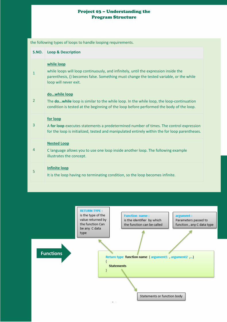
The most common syntax to define a function is −
Return type function name (argument1, argument2, …)
Statements;
Function Declaration
A function is declared outside any other functions, above or below the loop function.
We can declare the function in two different ways −
The first way is just writing the part of the function called a function prototype above the loop function,
which consists of −
Function return type
Function name
Function argument type, no need to write the argument name
Function prototype must be followed by a semicolon ( ; ).
The following example shows the demonstration of the function declaration using the first method.
Example
int sum_func (int x, int y) // function declaration
int z = 0;
z = x+y ;
return z; // return the value
void setup ()
Statements // group of statements
44
Project 03 – Understanding the
Program Structure
Example
int sum_func (int x, int y) // function declaration
int z = 0;
z = x+y ;
return z; // return the value
void setup ()
Statements // group of statements
Void loop ()
int result = 0 ;
result = Sum_func (5,6) ; // function call
The second part, which is called the function definition or declaration, must be declared below the loop
function, which consists of −
Function return type
Function name
Function argument type, here you must add the argument name
The function body (statements inside the function executing when the function is called)
The following example demonstrates the declaration of function using the second method.
Example
int sum_func (int , int ) ; // function prototype
void setup ()
Statements // group of statements
Void loop ()
int result = 0 ;
result = Sum_func (5,6) ; // function call
int sum_func (int x, int y) // function declaration
int z = 0;
z = x+y ;
return z; // return the value
The second method just declares the function above the loop function.

45
Project 03 – Understanding the
Program Structure
Now, it is time to use the analogWrite() function to
make a LED fade. Don’t forget that you will need one
LED, one 220Ω resistor, and some jumper wires.
Lastly, you will need at least 45 minutes to complete
the project.
To build the project, follow
the circuit diagram and hook
up the components on the
breadboard as shown in the
image given here.
46
Project 03 – Understanding the
Program Structure
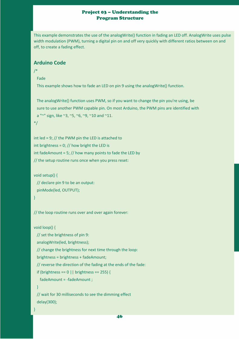
This example demonstrates the use of the analogWrite() function in fading an LED off. AnalogWrite uses pulse
width modulation (PWM), turning a digital pin on and off very quickly with different ratios between on and
off, to create a fading effect.
Arduino Code
/*
Fade
This example shows how to fade an LED on pin 9 using the analogWrite() function.
The analogWrite() function uses PWM, so if you want to change the pin you're using, be
sure to use another PWM capable pin. On most Arduino, the PWM pins are identified with
a "~" sign, like ~3, ~5, ~6, ~9, ~10 and ~11.
*/
int led = 9; // the PWM pin the LED is attached to
int brightness = 0; // how bright the LED is
int fadeAmount = 5; // how many points to fade the LED by
// the setup routine runs once when you press reset:
void setup()
// declare pin 9 to be an output:
pinMode(led, OUTPUT);
// the loop routine runs over and over again forever:
void loop()
// set the brightness of pin 9:
analogWrite(led, brightness);
// change the brightness for next time through the loop:
brightness = brightness + fadeAmount;
// reverse the direction of the fading at the ends of the fade:
if (brightness == 0 || brightness == 255)
fadeAmount = -fadeAmount ;
// wait for 30 milliseconds to see the dimming effect
delay(300);
47
Project 03 – Understanding the
Program Structure
Code to Note
After declaring pin 9 as your LED pin, there is nothing to do in the setup() function of your code. The
analogWrite() function that you will be using in the main loop of your code requires two arguments: One,
telling the function which pin to write to and the other indicating what PWM value to write.
In order to fade the LED off and on, gradually increase the PWM values from 0 (all the way off) to 255 (all the
way on), and then back to 0, to complete the cycle. In the sketch given above, the PWM value is set using a
variable called brightness. Each time through the loop, it increases by the value of the variable fadeAmount.
If brightness is at either extreme of its value (either 0 or 255), then fadeAmount is changed to its negative. In
other words, if fadeAmount is 5, then it is set to -5. If it is -5, then it is set to 5. The next time through the
loop, this change causes brightness to change direction as well.
analogWrite() can change the PWM value very fast, so the delay at the end of the sketch controls the speed
of the fade. Try changing the value of the delay and see how it changes the fading effect.
Result
You should see your LED brightness change gradually.
We have now gotten to the end
of this long project. In this
project you learnt about the loop
statements, if-else statements,
the operators, data types,
variables, and functions. Thank
you for sticking around. See you
in the next class.
48
Project 04 – Next Einstein (Know
how Hot you are)
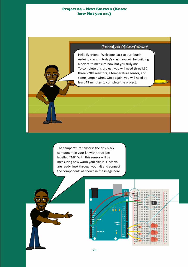
Hello Everyone! Welcome back to our fourth
Arduino class. In today’s class, you will be building
a device to measure how hot you truly are.
To complete this project, you will need three LED,
three 220Ω resistors, a temperature sensor, and
some jumper wires. Once again, you will need at
least 45 minutes to complete the project.
The temperature sensor is the tiny black
component in your kit with three legs
labelled TMP. With this sensor will be
measuring how warm your skin is. Once you
are ready, look through your kit and connect
the components as shown in the image here.

49
Project 04 – Next Einstein (Know
how Hot you are)
How to connect the components
1. Attach the cathode (short leg) of each of the LEDs you’re using to
ground through a 220-ohm resistor. Connect the anodes of the
LEDs to pins 2 through 4. These will be the indicators for the
project.
2. Place the TMP36 on the breadboard with the rounded part facing
away from the Arduino (the order of the pins is important!) as
shown in Fig. 2. Connect the left pin of the flat facing side to
power, and the right pin to ground. Connect the center pin to pin
A0 on your Arduino. This is analog input pin 0.
Please Note
the
following
The temperature sensor is a component that outputs a changing voltage depending on
the temperature it senses. It has three pins: one that connects to ground (GND),
another that connects to power, and a third that outputs a variable voltage to your
Arduino. In the sketch for this project, you’ll read the sensor’s output and use it to
turn LEDs on and off, indicating how warm you are. There are several different models
of temperature sensor. The model in your kit is the TMP36. TMP36 is convenient
because it outputs a voltage that changes directly proportional to the temperature in
degrees Celsius.
Moreover, the Arduino IDE comes with a tool called the serial monitor that enables
you to report back results from the microcontroller. Using the serial monitor, you can
get information about the status of sensors, and get an idea about what is happening
in your circuit and code as it runs.
The image depicts how the
Arduino IDE will output the
outcome of this project.

50
Project 04 – Next Einstein (Know
how Hot you are)
To build the code for this project, you
will need to know few new things
about the code. These information are
presented below.
Constants
Constants are similar to variables in that they allow you to uniquely name things
in the program, but unlike variables they cannot change. Name the analog input
for easy reference, and create another named constant to hold the baseline
temperature. For every 2 degrees above this baseline, an LED will turn on.
You’ve already seen the int datatype, used here to identify which pin the sensor
is on. The temperature is being stored as a float, or floating-point number. This
type of number has a decimal point, and is used for numbers that can be
expressed as fractions.
Serial.begin()
In the setup you’re going to use a new command, Serial. begin(). This opens up a connection between
the Arduino and the computer, so you can see the values from the analog input on your computer
screen.
The argument 9600 is the speed at which the Arduino will communicate, 9600 bits per second. You will
use the Arduino IDE’s serial monitor to view the information you choose to send from your
microcontroller. When you open the IDE’s serial monitor verify that the baud rate is 9600.
For() loop
Next up is a for() loop to set some pins as outputs. These are the pins that you attached LEDs to earlier.
Instead of giving them unique names and typing out the pinMode() function for each one, you can use a
for() loop to go through them all quickly. This is a handy trick if you have a large number of similar
things you wish to iterate through in a program. Tell the for() loop to run through pins 2 to 4
sequentially.
In the loop(), you’ll use a local variable named sensorVal to store the reading from your sensor. To get
the value from the sensor, you call analogRead() that takes one argument: what pin it should take a
voltage reading on. The value, which is between 0 and 1023, is a representation of the voltage on the
pin.
Serial.print()
The function Serial.print() sends information from the Arduino to a connected computer. You can see
this information in your serial monitor. If you give Serial.print() an argument in quotation marks, it will
print out the text you typed. If you give it a variable as an argument, it will print out the value of that
variable.
51
Project 04 – Next Einstein (Know
how Hot you are)
Serial.begin()
In the setup you’re going to use a new command, Serial. begin(). This opens up a connection between
the Arduino and the computer, so you can see the values from the analog input on your computer
screen.
The argument 9600 is the speed at which the Arduino will communicate, 9600 bits per second. You will
use the Arduino IDE’s serial monitor to view the information you choose to send from your
microcontroller. When you open the IDE’s serial monitor verify that the baud rate is 9600.
For() loop
Next up is a for() loop to set some pins as outputs. These are the pins that you attached LEDs to earlier.
Instead of giving them unique names and typing out the pinMode() function for each one, you can use a
for() loop to go through them all quickly. This is a handy trick if you have a large number of similar
things you wish to iterate through in a program. Tell the for() loop to run through pins 2 to 4
sequentially.
In the loop(), you’ll use a local variable named sensorVal to store the reading from your sensor. To get
the value from the sensor, you call analogRead() that takes one argument: what pin it should take a
voltage reading on. The value, which is between 0 and 1023, is a representation of the voltage on the
pin.
Serial.print()
The function Serial.print() sends information from the Arduino to a connected computer. You can see
this information in your serial monitor. If you give Serial.print() an argument in quotation marks, it will
print out the text you typed. If you give it a variable as an argument, it will print out the value of that
variable.
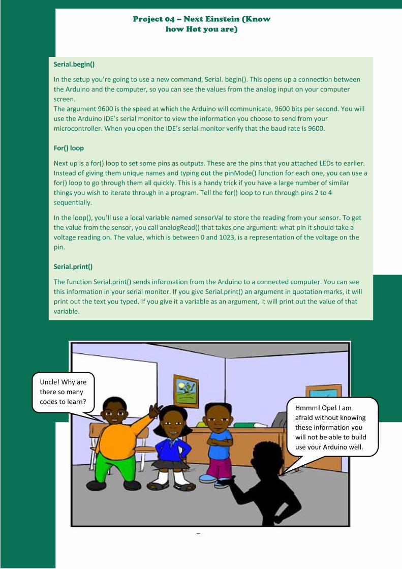
Uncle! Why are
there so many
codes to learn? Hmmm! Ope! I am
afraid without knowing
these information you
will not be able to build
use your Arduino well.
52
Project 04 – Next Einstein (Know
how Hot you are)
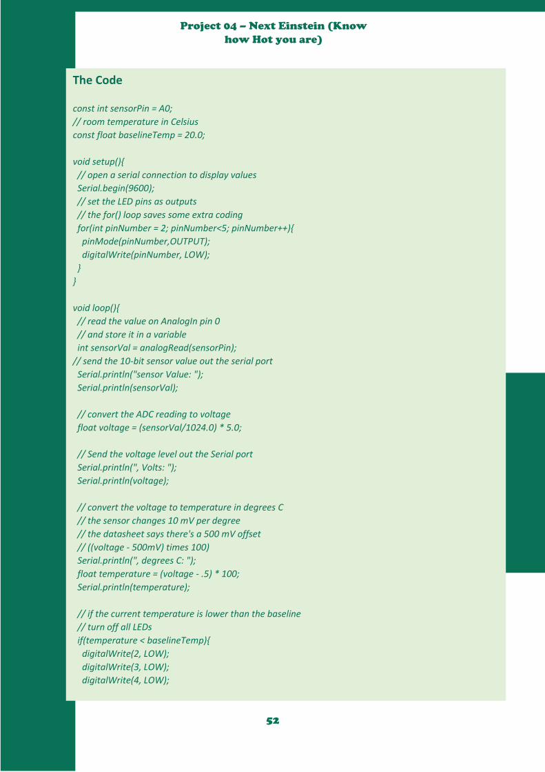
The Code
const int sensorPin = A0;
// room temperature in Celsius
const float baselineTemp = 20.0;
void setup()
// open a serial connection to display values
Serial.begin(9600);
// set the LED pins as outputs
// the for() loop saves some extra coding
for(int pinNumber = 2; pinNumber<5; pinNumber++)
pinMode(pinNumber,OUTPUT);
digitalWrite(pinNumber, LOW);
void loop()
// read the value on AnalogIn pin 0
// and store it in a variable
int sensorVal = analogRead(sensorPin);
// send the 10-bit sensor value out the serial port
Serial.println("sensor Value: ");
Serial.println(sensorVal);
// convert the ADC reading to voltage
float voltage = (sensorVal/1024.0) * 5.0;
// Send the voltage level out the Serial port
Serial.println(", Volts: ");
Serial.println(voltage);
// convert the voltage to temperature in degrees C
// the sensor changes 10 mV per degree
// the datasheet says there's a 500 mV offset
// ((voltage - 500mV) times 100)
Serial.println(", degrees C: ");
float temperature = (voltage - .5) * 100;
Serial.println(temperature);
// if the current temperature is lower than the baseline
// turn off all LEDs
if(temperature < baselineTemp)
digitalWrite(2, LOW);
digitalWrite(3, LOW);
digitalWrite(4, LOW);
53
Project 04 – Next Einstein (Know
how Hot you are)
// if the temperature rises 2-4 degrees, turn an LED on
else if(temperature >= baselineTemp+2 && temperature < baselineTemp+4)
digitalWrite(2, HIGH);
digitalWrite(3, LOW);
digitalWrite(4, LOW);
// if the temperature rises 4-6 degrees, turn a second LED on
else if(temperature >= baselineTemp+4 && temperature < baselineTemp+6)
digitalWrite(2, HIGH);
digitalWrite(3, HIGH);
digitalWrite(4, LOW);
// if the temperature rises more than 6 degrees, turn all LEDs on
else if(temperature >= baselineTemp+6)
digitalWrite(2, HIGH);
digitalWrite(3, HIGH);
digitalWrite(4, HIGH);
delay(100);
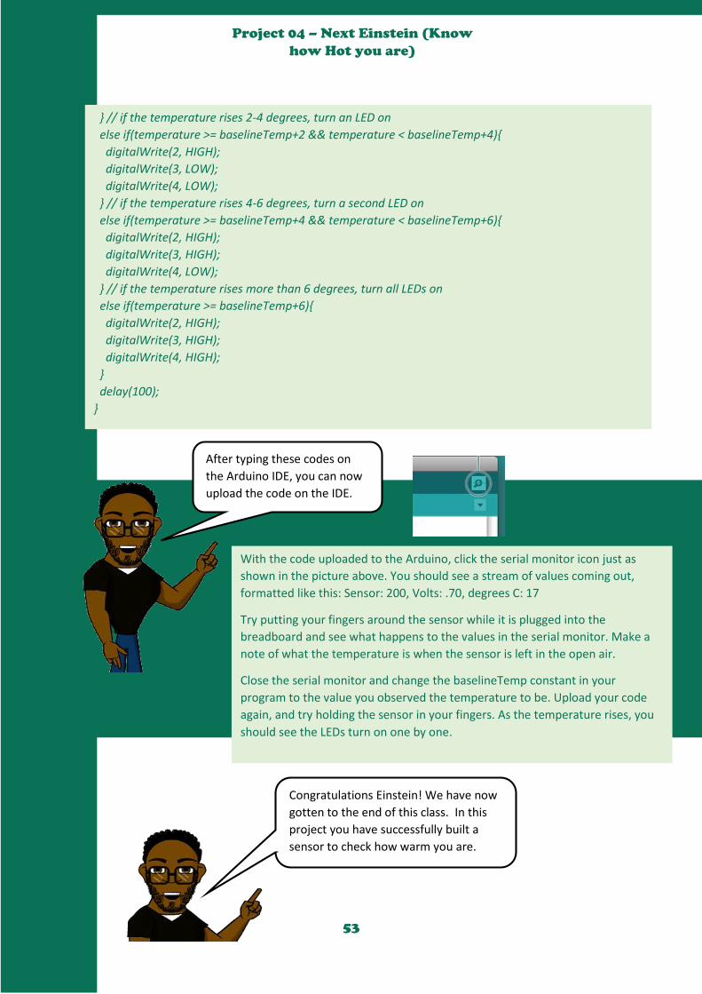
After typing these codes on
the Arduino IDE, you can now
upload the code on the IDE.
With the code uploaded to the Arduino, click the serial monitor icon just as
shown in the picture above. You should see a stream of values coming out,
formatted like this: Sensor: 200, Volts: .70, degrees C: 17
Try putting your fingers around the sensor while it is plugged into the
breadboard and see what happens to the values in the serial monitor. Make a
note of what the temperature is when the sensor is left in the open air.
Close the serial monitor and change the baselineTemp constant in your
program to the value you observed the temperature to be. Upload your code
again, and try holding the sensor in your fingers. As the temperature rises, you
should see the LEDs turn on one by one.
Congratulations Einstein! We have now
gotten to the end of this class. In this
project you have successfully built a
sensor to check how warm you are.

54
Project 05 – Welcome to YouNiversity
Hello Class! Welcome to YouNiversity! At the YouNiversity,
you have to do the following:
Go to YouTube
Find an Arduino project
Follow how it was built and build it
Then, present your project to your friends explaining to
them why you selected the project, what you have
learnt, and how others can learn from the project.

55
Project 06 – Colour Mixing Lamp
Hello Class! Welcome back from YouNiversity! Hope you
learnt one or two vital lessons. Now we carry on with
our remaining projects. In this project, you will create a
lamp that changes its color depending on the room's
lighting conditions. Shine red and blue light on a set of
three light sensors, and the LED will turn purple! This
project uses three analog inputs and you will watch data
from the sensor in the "serial monitor."
Using a tri-colour LED and three photoresistors,
you will be creating a lamp that smoothly
changes colours depending on external lighting
conditions. So if you are ready, connect your
components as shown in the image here.
You will need the following electrical
components for this project: one RGB
LED, three 220Ω resistors, three 10
kΩ resistors, three photoresistors,
and at least 45 Minutes.
56
Project 06 – Colour Mixing Lamp
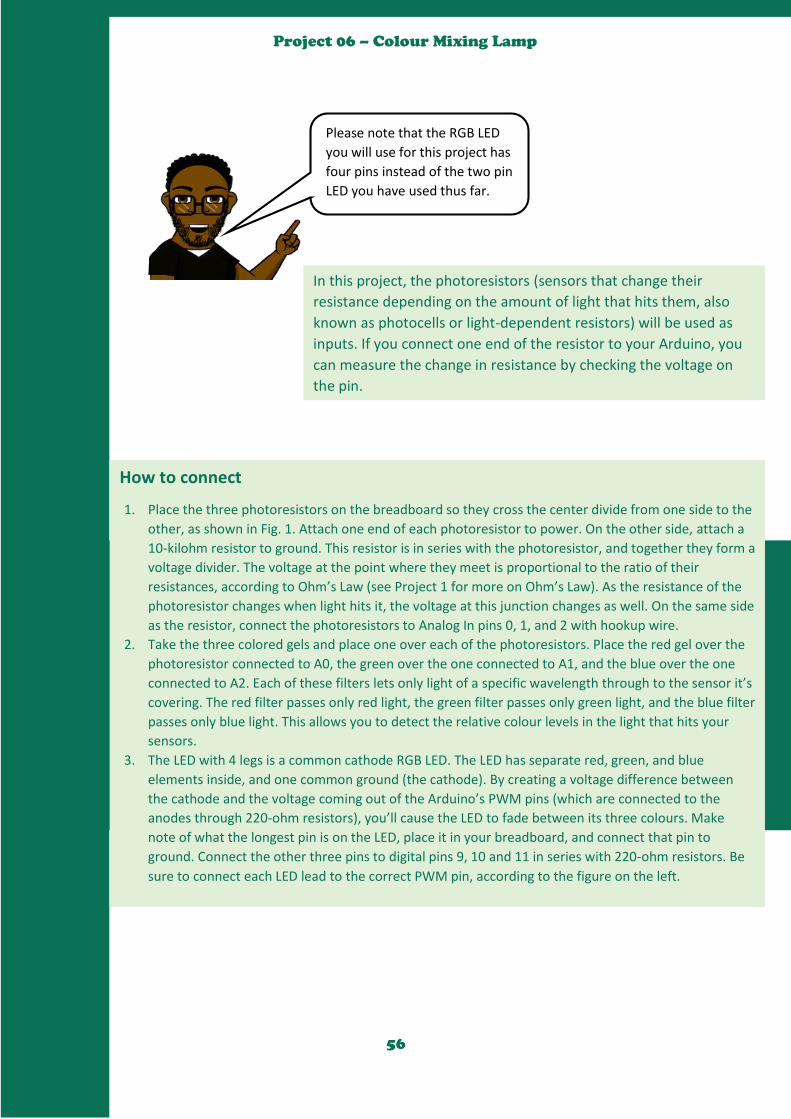
Please note that the RGB LED
you will use for this project has
four pins instead of the two pin
LED you have used thus far.
How to connect
1. Place the three photoresistors on the breadboard so they cross the center divide from one side to the
other, as shown in Fig. 1. Attach one end of each photoresistor to power. On the other side, attach a
10-kilohm resistor to ground. This resistor is in series with the photoresistor, and together they form a
voltage divider. The voltage at the point where they meet is proportional to the ratio of their
resistances, according to Ohm’s Law (see Project 1 for more on Ohm’s Law). As the resistance of the
photoresistor changes when light hits it, the voltage at this junction changes as well. On the same side
as the resistor, connect the photoresistors to Analog In pins 0, 1, and 2 with hookup wire.
2. Take the three colored gels and place one over each of the photoresistors. Place the red gel over the
photoresistor connected to A0, the green over the one connected to A1, and the blue over the one
connected to A2. Each of these filters lets only light of a specific wavelength through to the sensor it’s
covering. The red filter passes only red light, the green filter passes only green light, and the blue filter
passes only blue light. This allows you to detect the relative colour levels in the light that hits your
sensors.
3. The LED with 4 legs is a common cathode RGB LED. The LED has separate red, green, and blue
elements inside, and one common ground (the cathode). By creating a voltage difference between
the cathode and the voltage coming out of the Arduino’s PWM pins (which are connected to the
anodes through 220-ohm resistors), you’ll cause the LED to fade between its three colours. Make
note of what the longest pin is on the LED, place it in your breadboard, and connect that pin to
ground. Connect the other three pins to digital pins 9, 10 and 11 in series with 220-ohm resistors. Be
sure to connect each LED lead to the correct PWM pin, according to the figure on the left.
In this project, the photoresistors (sensors that change their
resistance depending on the amount of light that hits them, also
known as photocells or light-dependent resistors) will be used as
inputs. If you connect one end of the resistor to your Arduino, you
can measure the change in resistance by checking the voltage on
the pin.
57
Project 06 – Colour Mixing Lamp
The Code
const int greenLEDPin=9;
const int blueLEDPin=10;
const int redLEDPin=11;
const int redSensorPin=A0;
const int greenSensorPin=A1;
const int blueSensorPin=A2;
int redValue=0;
int greenValue=0;
int blueValue=0;
int redSensorValue=0;
int greenSensorValue=0;
int blueSensorValue=0;
void setup()
Serial.begin(9600);
pinMode(greenLEDPin,OUTPUT);
pinMode(blueLEDPin,OUTPUT);
pinMode(redLEDPin,OUTPUT);
void loop()
redSensorValue=analogRead(redSensorPin);
delay(5);
greenSensorValue=analogRead(greenSensorPin);
delay(5);
blueSensorValue=analogRead(blueSensorPin);
Serial.print(“Raw Sensor Value \t red: “);
Serial.print(redSensorValue);
Serial.print(” \t green: “);
Serial.print(greenSensorValue);
Serial.print(” \t blue: “);
Serial.println(blueSensorValue);

58
Project 06 – Colour Mixing Lamp
The Code - continued //report the calculated LED light levels
redValue=redSensorValue/4;
greenValue=greenSensorValue/4;
blueValue=blueSensorValue/4;
Serial.print(“Maped Sensor Value \t red: “);
Serial.print(redValue);
Serial.print(” \t green: “);
Serial.print(greenValue);
Serial.print(” \t blue: “);
Serial.println(blueValue);
analogWrite(redLEDPin,redValue);
analogWrite(greenLEDPin,greenValue);
analogWrite(blueLEDPin,blueValue);
analogWrite(redLEDPin,redValue);
analogWrite(greenLEDPin,greenValue);
analogWrite(blueLEDPin,blueValue);
Use it Once you have your Arduino programmed and wired up, open the serial monitor. The LED will probably be
an off-white colour, depending on the predominant colour of the light in your room. Look at the values
coming from the sensors in the serial monitor, if you’re in an environment with stable lighting, the number
should probably be fairly consistent.
Turn off the light in the room you’re in and see what happens to the values of the sensors. With a
flashlight, illuminate each of the sensors individually and notice how the values change in the serial
monitor, and notice how the LED’s colour changes. When the photoresistors are covered with a gel, they
only re-act to light of a certain wavelength. This will give you the opportunity to change each of the
colours independently.
We have now gotten to the
end of this project. Hope to
see you in our next class.

59
Project 07 – Mood Cue
Welcome back to our Arduino class!
Arriving to this project means not only that
you are starting to familiarize with Arduino,
but also that you are determined to be able
to create amazing things with it. So first of
all, we would like to congratulate you.
The knowledge you have gained so
far is really important, but we really
have to step things up by learning
how to make things move. For this
purpose, a servomotor is going to be
used. So let us begin.
In today’s class, you will be making use
of the following, one potentiometer,
one Servomotor, two 100UF Capacitors,
three male header pins, and as usual
some jumper wires. Lastly, this project
will require at least 60 minutes of your
time. But before we proceed further, we
will be giving a short explanation of the
servomotor below.

60
Project 07 – Mood Cue
The picture here shows what the Servo motor
looks like. Servo motors are a special type of
motor that don’t spin around in a circle, but move
to a specific position and stay there until you tell
them to move again. Servos usually only rotate
180 degrees (one half of a circle).
Similar to the way you used pulses to PWM an LED in the Colour Mixing Lamp Project, servo
motors expect a number of pulses that tell them what angle to move to. The pulses always come
at the same time intervals, but the width varies between 1000 and 2000 microseconds. While it’s
possible to write code to generate these pulses, the Arduino software comes with a library that
allows you to easily control the motor.
Because the servo only rotates 180 degrees, and your analog input goes from 0-1023, you’ll need
to use a function called map() to change the scale of the values coming from the potentiometer.
One of the great things about the Arduino community are the talented people who extend its
functionality through additional software. It’s possible for anyone to write libraries to extend the
Arduino’s functionality. There are libraries for a wide variety of sensors and actuators and other
devices that users have contributed to the community. A software library expands the
functionality of a programming environment. The Arduino software comes with a number of
libraries that are useful for working with hardware or data. One of the included libraries is
designed to use with servo motors. In your code, you’ll import the library, and all of its
functionality will be available to you.
Before reading the code, note that a servomotor library is being used. After importing it, you can
use all the functions that contains making the code much easier.
As it is shown in the picture below, the potentiometer must be connected to an analog input as
long as to the 5V entry and to the ground (GND). Otherwise, the servo must be to a digital input
as well as to the 5V and the GND. Make sure you connect the capacitors properly as they have
polarity.
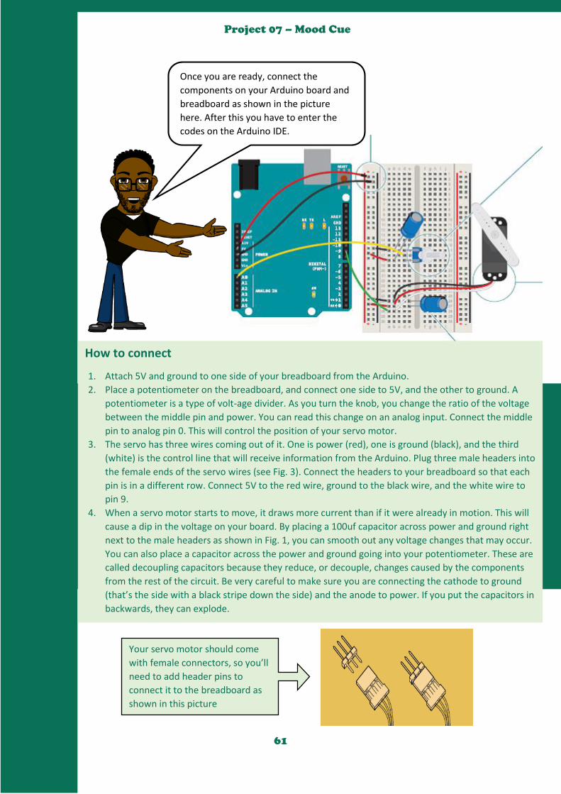
61
Project 07 – Mood Cue
Once you are ready, connect the
components on your Arduino board and
breadboard as shown in the picture
here. After this you have to enter the
codes on the Arduino IDE.
How to connect
1. Attach 5V and ground to one side of your breadboard from the Arduino.
2. Place a potentiometer on the breadboard, and connect one side to 5V, and the other to ground. A
potentiometer is a type of volt-age divider. As you turn the knob, you change the ratio of the voltage
between the middle pin and power. You can read this change on an analog input. Connect the middle
pin to analog pin 0. This will control the position of your servo motor.
3. The servo has three wires coming out of it. One is power (red), one is ground (black), and the third
(white) is the control line that will receive information from the Arduino. Plug three male headers into
the female ends of the servo wires (see Fig. 3). Connect the headers to your breadboard so that each
pin is in a different row. Connect 5V to the red wire, ground to the black wire, and the white wire to
pin 9.
4. When a servo motor starts to move, it draws more current than if it were already in motion. This will
cause a dip in the voltage on your board. By placing a 100uf capacitor across power and ground right
next to the male headers as shown in Fig. 1, you can smooth out any voltage changes that may occur.
You can also place a capacitor across the power and ground going into your potentiometer. These are
called decoupling capacitors because they reduce, or decouple, changes caused by the components
from the rest of the circuit. Be very careful to make sure you are connecting the cathode to ground
(that’s the side with a black stripe down the side) and the anode to power. If you put the capacitors in
backwards, they can explode.
Your servo motor should come
with female connectors, so you’ll
need to add header pins to
connect it to the breadboard as
shown in this picture

62
Project 07 – Mood Cue
The Code
#include <Servo.h>
Servo TestServo;
int const potPin=A0;
int potValue;
int angle;
void setup()
TestServo.attach(9);
Serial.begin(9600);
void loop()
potValue=analogRead(potPin);
Serial.print(“potValue: “);
Serial.print(potValue);
angle=map(potValue, 0,1023,0,179);
Serial.print(“,angle: “);
Serial.println(angle);
TestServo.write(angle);
delay(15);
How it works
To use the servo library, you’ll first need to import it. This makes the additions from the library
available to your sketch.
To refer to the servo, you’re going to need to create a named instance of the servo library in a
variable. This is called an object. When you do this, you’re making a unique name that will have all the
functions and capabilities that the servo library offers. From this point on in the program, every time
you refer to myServo, you’ll be talking to the servo object.
Set up a named constant for the pin the potentiometer is attached to, and variables to hold the
analog input value and angle you want the servo to move to.
In the setup(), you’re going to need to tell the Arduino what pin your servo is attached to.
Include a serial connection so you can check the values from the potentiometer and see how they
map to angles on the servo motor.
In the loop(), read the analog input and print out the value to the serial monitor.
To create a usable value for the servo motor from your analog input, it’s easiest to use the map()
function. This handy function scales numbers for you. In this case it will change values between 0-
1023 to values between 0-179. It takes five arguments : the number to be scaled (here it’s potVal),
the minimum value of the input (0), the maximum value of the input (1023), the minimum value of
the output (0), and the maximum value of the output (179). Store this new value in the angle variable.
Then, print out the mapped value to the serial monitor.
Finally, it’s time to move the servo. The command servo. write() moves the motor to the angle you
specify. At the end of the loop() put a delay so the servo has time to move to its new position.

63
Project 07 – Mood Cue
Once your Arduino has been
programmed and powered up, open
the serial monitor. You should see a
stream of values similar to the one
here
potVal : 1023, angle : 179
potVal : 1023, angle : 179
When you turn the potentiometer, you should see the
numbers change. More importantly, you should see your
servo motor move to a new position. Notice the
relationship be-tween the value of potVal and angle in
the serial monitor and the position of the servo. You
should see consistent results as you turn the pot.
One nice thing about using potentiometers as analog
inputs is that they will give you a full range of values
between 0 and 1023. This makes them helpful in testing
projects that use analog input.
Congratulations! You have successfully
completed the project. In this project
you learnt how t make things move using
a servo motor. Now, your dream of
making your toy robots is 70%
accomplished. See you in the next class.

64
Project 08 – Little Symphony
Welcome back to our Arduino class! Hope
you are still in a good mood after the last
class. Today we will be doing another
spectacular project. In today’s project we
will be building a little symphony using a
theremin.
A theremin is an instrument that makes sounds
based on the movements of a musician’s hands
around the instrument. A piezo is a small element
that vibrates when it receives electricity. When it
moves, it displaces air around it, creating sound
waves. To build project, a Piezo element, a
Photoresistor, and a 10KΩ resistor. Lastly, you will
need 45 minutes to complete the project.
Uncle! What
is a Theremin
and Piezo?

65
Project 08 – Little Symphony
Once you are ready please make the
connection as shown on this picture.
In case you need more information on
the components, please consult the
introduction.
The theremin detects where a performer’s hands are in
relation to two antennas by reading the capacitive
change on the antennas. These antennas are connected
to analog circuitry that create the sound. One antenna
controls the frequency of the sound and the other
controls volume. While the Arduino can’t exactly
replicate the mysterious sounds from this instrument, it
is possible to emulate them using the tone() function.
Instead of sensing capacitance with the Arduino, you’ll be using a photoresistor to detect the amount of
light. By moving your hands over the sensor, you’ll change the amount of light that falls on the
photoresistor’s face, as you did in Project 4. The change in the voltage on the analog pin will determine
what frequency note to play.
You’ll connect the photoresistors to the Arduino using a voltage divider circuit like you did in Project 4. You
probably noticed in the earlier project that when you read this circuit using analogRead(), your readings
didn’t range all the way from 0 to 1023. The fixed resistor connecting to ground limits the low end of the
range, and the brightness of your light limits the high end. Instead of settling for a limited range, you’ll
calibrate the sensor readings getting the high and low values, mapping them to sound frequencies using
the map() function to get as much range out of your theremin as possible. This will have the added benefit
of adjusting the sensor readings whenever you move your circuit to a new environment, like a room with
different light conditions.
Take your piezo, and connect one end to
ground, and the other to digital pin 8 on the
Arduino.
Place your photoresistor on the breadboard,
connecting one end to 5V. Connect the
other end to the Arduino’s analogIn pin 0,
and to ground through a 10-kilohm resistor.
This circuit is the same as the voltage divider
circuit in Project 4.

66
Project 08 – Little Symphony
About the Code
Create a variable to hold the analogRead() value from the photoresistor. Next, create variables for
the high and low values. You’re going to set the initial value in the sensorLow variable to 1023, and
set the value of the sensorHigh variable to 0. When you first run the program, you’ll compare these
numbers to the sensor’s readings to find the real maximum and minimum values.
Create a constant named ledPin. You’ll use this as an indicator that your sensor has finished
calibrating. For this project, use the on-board LED connected to pin 13.
In the setup(), change the pinMode() of ledPin to OUTPUT, and turn the light on.
The next steps will calibrate the sensor’s maximum and minimum values. You’ll use a while()
statement to run a loop for 5 seconds. while() loops run until a certain condition is met. In this case
you’re going to use the millis() function to check the current time. millis() reports how long the
Arduino has been running since it was last powered on or reset.
In the loop, you’ll read the value of the sensor; if the value is less than sensorLow (initially 1023),
you’ll update that variable. If it is greater than sensorHigh (initially 0), that gets updated.
When 5 seconds have passed, the while() loop will end. Turn off the LED attached to pin 13. You’ll
use the sensor high and low values just recorded to scale the frequency in the main part of your
program.
In the loop(), read the value on A0 and store it in sensorValue.
Create a variable named pitch. The value of pitch is going to be mapped from sensorValue. Use
sensorLow and sensorHigh as the bounds for the incoming values. For starting values for output, try
50 to 4000. These numbers set the range of frequencies the Arduino will generate.
Next, call the tone() function to play a sound. It takes three arguments : what pin to play the sound
on (in this case pin 8), what frequency to play (determined by the pitch variable), and how long to
play the note (try 20 milliseconds to start).
Then, call a delay() for 10 milliseconds to give the sound some time to play.
Once you are done, then
enter the code on the
next page in your
Arduino IDE.
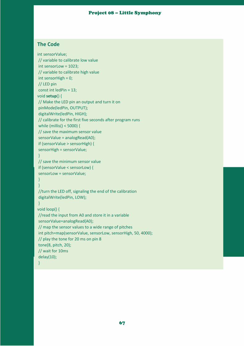
67
Project 08 – Little Symphony
The Code
int sensorValue;
// variable to calibrate low value
int sensorLow = 1023;
// variable to calibrate high value
int sensorHigh = 0;
// LED pin
const int ledPin = 13;
void setup()
// Make the LED pin an output and turn it on
pinMode(ledPin, OUTPUT);
digitalWrite(ledPin, HIGH);
// calibrate for the first five seconds after program runs
while (millis() < 5000)
// save the maximum sensor value
sensorValue = analogRead(A0);
if (sensorValue > sensorHigh)
sensorHigh = sensorValue;
// save the minimum sensor value
if (sensorValue < sensorLow)
sensorLow = sensorValue;
//turn the LED off, signaling the end of the calibration
digitalWrite(ledPin, LOW);
void loop()
//read the input from A0 and store it in a variable
sensorValue=analogRead(A0);
// map the sensor values to a wide range of pitches
int pitch=map(sensorValue, sensorLow, sensorHigh, 50, 4000);
// play the tone for 20 ms on pin 8
tone(8, pitch, 20);
// wait for 10ms
delay(10);

68
Project 08 – Little Symphony
How it works
When you first power the Arduino on, there is a 5 second window for you to calibrate the sensor.
To do this, move your hand up and down over the photoresistor, changing the amount of light that
reaches it. The closer you replicate the motions you expect to use while playing the instrument, the
better the calibration will be.
After 5 seconds, the calibration will be complete, and the LED on the Arduino will turn off. When
this happens, you should hear some noise coming from the piezo! As the amount of light that falls
on the sensor changes, so should the frequency that the piezo plays.
Congratulations! It is
time for a little
jamboree! So let’s
dance everybody!
Three GBOSA
for GreenLab!
GBOSA!
GBOSA!!
GBOSA!!! GBOSA!
GBOSA!!
GBOSA!!!

69
Project 09 – Welcome back to
YouNiversity
Hello Class! Welcome back to YouNiversity! Just like you did
in the last YouNiversity, once again:
Go to YouTube
Find an Arduino project
Follow how it was built and build it
Then, present your project to your friends explaining to
them why you selected the project, what you have
learnt, and how others can learn from the project.

70
Project 10 – Piano
Hello Class! Welcome back from YouNiversity!
Without doubt I know you are learning while
having as much fun as you can. To carry on with
our Music lessons we will be building a little
Piano that has 4 notes. Who knows what those
notes are?
Uncle! Me! Uncle! Please
can I try?
Tayo please
try.
It is Do Re Mi
Fa. Oh Yes!
Exactly!

71
Project 10 – Piano
As we wanted the instrument to have 4 notes, we put four switches in
parallel. In three branches we connected a resistor in series with the
switch and in the fourth one a wire connected directly to power. This
kind of structure is called a mixed resistor circuit. Each resistor had a
different value, so every time we pushed one switch the voltage read
by the analogic entrance was different. Then, in function of this value,
the piezometer vibrated at a different frequency.
To build this project, you will need four
switches, your Piezo, one 10KΩ, one 220Ω, and
one 1MΩ. Finally, just like the previous projects
you will need at least 45 minutes to complete
this project. But I encourage you not to rush,
take your time and have fun while you learn.
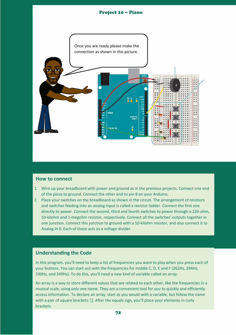
72
Project 10 – Piano
Once you are ready please make the
connection as shown in this picture.
How to connect
1. Wire up your breadboard with power and ground as in the previous projects. Connect one end
of the piezo to ground. Connect the other end to pin 8 on your Arduino.
2. Place your switches on the breadboard as shown in the circuit. The arrangement of resistors
and switches feeding into an analog input is called a resistor ladder. Connect the first one
directly to power. Connect the second, third and fourth switches to power through a 220-ohm,
10-kilohm and 1-megohm resistor, respectively. Connect all the switches’ outputs together in
one junction. Connect this junction to ground with a 10-kilohm resistor, and also connect it to
Analog In 0. Each of these acts as a voltage divider.
Understanding the Code
In this program, you’ll need to keep a list of frequencies you want to play when you press each of
your buttons. You can start out with the frequencies for middle C, D, E and F (262Hz, 294Hz,
330Hz, and 349Hz). To do this, you’ll need a new kind of variable called an array.
An array is a way to store different values that are related to each other, like the frequencies in a
musical scale, using only one name. They are a convenient tool for you to quickly and efficiently
access information. To declare an array, start as you would with a variable, but follow the name
with a pair of square brackets: []. After the equals sign, you’ll place your elements in curly
brackets.
To read or change the elements of the array, you reference the individual element using the array
name and then the index of the item you want to address. The index refers to the order in which
the items appear when the array is created. The first item in the array is item 0, the second is item
1, and so forth.

73
Project 10 – Piano
To read or change the elements of the array, you reference the individual element using the array
name and then the index of the item you want to address. The index refers to the order in which
the items appear when the array is created. The first item in the array is item 0, the second is item
1, and so forth.
Set up an array of four notes using the frequencies listed above. Make this array a global variable
by declaring it before the setup().
In your setup(), start serial communication with the computer.
In the loop(), declare a local variable to hold the value read on pin A0. Because each switch has a
different resistor value connecting it to power, each will have a different value associated with it.
To see the values, add the line Serial. println(keyVal) to send to the computer.
Using an if()...else statement, you can assign each value to a different tone. The values included in
the example program are ballpark figures for these resistor sizes. As all resistors have some
tolerance for error, these may not work exactly for you. Use the information from the serial
monitor to adjust as necessary.
After each if() statement, call the tone() function. The program references the array to determine
what frequency to play. If the value of A0 matches one of your if statements, you can tell the
Arduino to play a tone. It’s possible your circuit is a little “noisy” and the values may fluctuate a
little bit while pressing a switch. To accommodate for this variation, it’s a good idea to have a small
range of values to check against. If you use the comparison “&&”, you can check multiple
statements to see if they are true.
If you press the first button, notes[0] will play. If you press the second, notes[1] will play, and if
you press the third, notes[2] will play. This is when arrays become really handy.
Only one frequency can play on a pin at any given time, so if you’re pressing multiple keys, you’ll
only hear one sound.
To stop playing notes when there is no button being pressed, call the noTone() function, providing
the pin number to stop playing sound on.
If your resistors are close in value to the values in the example program, you should hear some
sounds from the piezo when you press the buttons. If not, check the serial monitor to make sure
each of the buttons is in a range that corresponds to the notes in the if()...else statement. If you’re
hearing a sound that seems to stutter, try increasing the range a little bit.
Press multiple buttons at the same time, and see what sort of values you get in the serial monitor.
Use these new values to trigger even more sounds. Experiment with different frequencies to
expand your musical output. You can find frequencies of musical notes on this page:
arduino.cc/frequencies
74
Project 10 – Piano
The Code
//Create a matrix with the frequencies of the musical notes C4,D4,E4,F4
int notes[ ]=262,294,330,349;
void setup()
//To force transmission speed between Arduino and the computer to be 9600 bytes/second
Serial.begin(9600);
void loop()
int PushedKeyValue=analogRead(A0);
Serial.println(PushedKeyValue);
//Depending on the value obtained, we make the piezometre vibrate at the correspondant
frequence. If PushedKeyValue==1023 it will be a C4, for example.
if (PushedKeyValue==1023)
tone(8,notes[0]);
else if (PushedKeyValue >=990 && PushedKeyValue<=1010)
tone(8,notes[1]);
else if (PushedKeyValue >=505 && PushedKeyValue<=515)
tone(8,notes[2]);
else if (PushedKeyValue >=5 && PushedKeyValue<=10)
tone(8,notes[3]);
else
noTone(8);
If your resistors are close in value to the values in the example program, you should hear some
sounds from the piezo when you press the buttons. If not, check the serial monitor to make sure
each of the buttons is in a range that corresponds to the notes in the if()...else statement. If you’re
hearing a sound that seems to stutter, try increasing the range a little bit.
Press multiple buttons at the same time, and see what sort of values you get in the serial monitor.
Use these new values to trigger even more sounds. Experiment with different frequencies to
expand your musical output. You can find frequencies of musical notes on this page:
arduino.cc/frequencies
75
Project 10 – Piano
Thank you for your time and
attention. Please try if you can
build a 5 notes or 6 notes piano.
We are now at the end of
today’s class.

76
Project 11 - Digital Hourglass
Hello Class! Welcome back to
our Arduino class. In today’s
class we will be digitizing the
hour glass.
Uncle! Please can I ask
a question? What is an
hour glass?
That’s a great question Tayo! This is an Hourglass, and
it is a device used to measure time in the olden days.
It has two glass compartments from which sand runs
from the upper compartment to the lower one. In our
project, the sand will be replaced by some LEDs and a
tilt switch (also known as mercury switch) will detect
when the hourglass turns.
Oh yes! I remember
seeing it in one of
my cartoons.

77
Project 11 - Digital Hourglass
In today’s class, you will be making use
of the following, six LEDs, six 220Ω
resistor, one 10KΩ, one tilt switch, and
as usual some jumper wires. Lastly, this
project will require at least 30 minutes
of your time. But please spend as much
time as required so you can fully
understand the project.
During this project you will learn about tilt switches and how to use them. In addition, we are using
the millis() function , which is going to replace delay(). Long variables are being introduced too.
Up to now, when you’ve wanted something to happen at a specific time interval with the Arduino,
you’ve used delay(). This is handy, but a little confining. When the Arduino calls delay(), it freezes its
current state for the duration of the delay. That means there can be no other input or output while it’s
waiting. Delays are also not very helpful for keeping track of time. If you wanted to do something
every 10 seconds, having a 10 second delay would be fairly cumbersome.
The millis() function helps to solve these problems. It keeps track of the time your Arduino has been
running in milliseconds. You used it previously in Project 6 when you created a timer for calibration.
So far you’ve been declaring variables as int. An int (integer) is a 16-bit number, it holds values
between -32,768 and 32,767. Those may be some large numbers, but if the Arduino is counting 1000
times a second with millis(), you’d run out of space in less than a minute. The long datatype holds a 32-
bit number (between -2,147,483,648 and 2,147,483,647). Since you can’t run time backwards to get
negative numbers, the variable to store millis() time is called an unsigned long. When a datatype is
called unsigned, it is only positive. This allows you to count even higher. An unsigned long can count
up to 4,294,967,295. That’s enough space for millis() to store time for almost 50 days. By comparing
the current millis() to a specific value, you can see if a certain amount of time has passed.
When you turn your hourglass over, a tilt switch will change its state, and that will set off another
cycle of LEDs turning on.
The tilt switch works just like a regular switch in that it is an on/off sensor. You’ll use it here as a digital
input. What makes tilt switches unique is that they detect orientation. Typically they have a small
cavity inside the housing that has a metal ball. When tilted in the proper way, the ball rolls to one side
of the cavity and connects the two leads that are in your breadboard, closing the switch.
With six LEDs, your hourglass will run for an hour, just as its name implies.
78
Project 11 - Digital Hourglass
Understanding the Code
1. You’re going to need a number of global variables in your program to get this all working. To
start, create a constant named switchPin. This will be the name of the pin your tilt switch is on.
2. Create a variable of type unsigned long, This will hold the time an LED was last changed.
3. Create a variable for the switch state, and another to hold the previous switch state. You’ll use
these two to compare the switch’s position from one loop to the next.
4. Create a variable named led. This will be used to count which LED is the next one to be turned
on. Start out with pin 2.
5. The last variable you’re creating is going to be the interval between each LED turning on. This
will be be a long datatype. In 10 minutes (the time between each LED turning on) 600,000
milliseconds pass. If you want the delay between lights to be longer or shorter, this is the
number you change.
6. In your setup(), you need to declare the LED pins 2-7 as outputs. A for() loop declares all six as
OUTPUT with just 3 lines of code. You also need to declare switchPin as an INPUT.
7. When the loop() starts, you’re going to get the amount of time the Arduino has been running
with millis() and store it in a local variable named currentTime.
8. Using an if() statement, you’ll check to see if enough time has passed to turn on an LED.
Subtract the currentTime from the previousTime and check to see if it is greater than the
interval variable. If 600,000 milliseconds have passed (10 minutes), you’ll set the variable
previousTime to the value of currentTime.
9. previousTime indicates the last time an LED was turned on. Once you’ve set previousTime,
turn on the LED, and increment the led variable. The next time you pass the time interval, the
next LED will light up.
10. Add one more if statement in the program to check if the LED on pin 7 is turned on. Don’t do
anything with this yet. You’ll decide what happens at the end of the hour later.
11. Now that you’ve checked the time, you’ll want to see if the switch has changed its state. Read
the switch value into the switchState variable.
12. With an if() statement, check to see if the switch is in a different position than it was
previously. The != evaluation checks to see if switchState does not equal prevSwitchState. If
they are different, turn the LEDs off, return the led variable to the first pin, and reset the timer
for the LEDs by setting previousTime to currentTime.
13. At the end of the loop(), save the switch state in prevSwitchState , so you can compare it to
the value you get for switchState in the next loop().
How to connect
1. Connect power and ground to your breadboard.
2. Connect the anode (longer leg) of six LEDs to digital pins 2-7. Connect the LEDs to ground
through 220-ohm resistors.
3. Connect one lead of the tilt switch to 5V. Connect the other to a 10-kilohm resistor to ground.
Connect the junction where they meet to digital pin 8.
You don’t need to have your Arduino tethered to the computer for this to work. Try building a
stand with some cardboard or styrofoam and power the Arduino with a battery to make a portable
version. You can create a cover with some numeric indicators alongside the lights.

79
Project 11 - Digital Hourglass
The Code
const int switchPin = 8;
unsigned long previousTime = 0;
int switchState = 0;
int prevSwitchState = 0;
int led = 2;
long interval = 600000;
void setup()
for(int x = 2;x<8;x++) pinMode(x, OUTPUT);
pinMode(switchPin, INPUT);
void loop()
unsigned long currentTime = millis();
if(currentTime - previousTime > interval)
previousTime = currentTime;
digitalWrite(led, HIGH);
led++;
if(led == 7)
switchState = digitalRead(switchPin);
if(switchState != prevSwitchState)
for(int x = 2;x<8;x++) digitalWrite(x, LOW);
led = 2;
previousTime = currentTime;
prevSwitchState = switchState;
We are now at the end of
today’s class. Please do not
hesitate to ask your tutor for
help or check online for more
information. See you in the next
class.
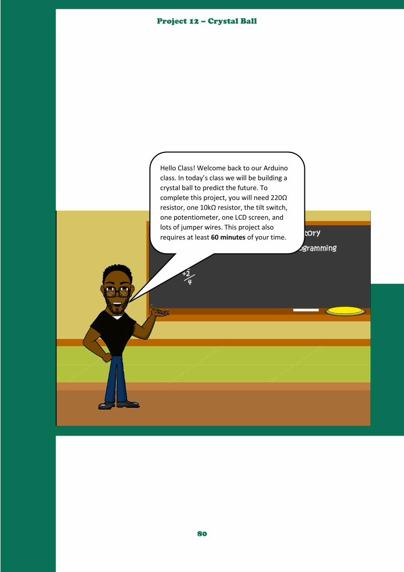
80
Project 12 – Crystal Ball
Hello Class! Welcome back to our Arduino
class. In today’s class we will be building a
crystal ball to predict the future. To
complete this project, you will need 220Ω
resistor, one 10kΩ resistor, the tilt switch,
one potentiometer, one LCD screen, and
lots of jumper wires. This project also
requires at least 60 minutes of your time.
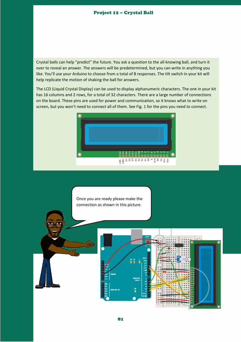
81
Project 12 – Crystal Ball
Crystal balls can help “predict” the future. You ask a question to the all-knowing ball, and turn it
over to reveal an answer. The answers will be predetermined, but you can write in anything you
like. You’ll use your Arduino to choose from a total of 8 responses. The tilt switch in your kit will
help replicate the motion of shaking the ball for answers.
The LCD (Liquid Crystal Display) can be used to display alphanumeric characters. The one in your kit
has 16 columns and 2 rows, for a total of 32 characters. There are a large number of connections
on the board. These pins are used for power and communication, so it knows what to write on
screen, but you won’t need to connect all of them. See Fig. 1 for the pins you need to connect.
Once you are ready please make the
connection as shown in this picture.
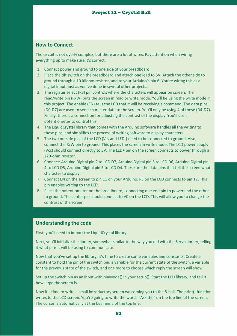
82
Project 12 – Crystal Ball
How to Connect
The circuit is not overly complex, but there are a lot of wires. Pay attention when wiring
everything up to make sure it’s correct.
1. Connect power and ground to one side of your breadboard.
2. Place the tilt switch on the breadboard and attach one lead to 5V. Attach the other side to
ground through a 10-kilohm resistor, and to your Arduino’s pin 6. You’re wiring this as a
digital input, just as you’ve done in several other projects.
3. The register select (RS) pin controls where the characters will appear on screen. The
read/write pin (R/W) puts the screen in read or write mode. You’ll be using the write mode in
this project. The enable (EN) tells the LCD that it will be receiving a command. The data pins
(D0-D7) are used to send character data to the screen. You’ll only be using 4 of these (D4-D7).
Finally, there’s a connection for adjusting the contrast of the display. You’ll use a
potentiometer to control this.
4. The LiquidCrystal library that comes with the Arduino software handles all the writing to
these pins, and simplifies the process of writing software to display characters.
5. The two outside pins of the LCD (Vss and LED-) need to be connected to ground. Also,
connect the R/W pin to ground. This places the screen in write mode. The LCD power supply
(Vcc) should connect directly to 5V. The LED+ pin on the screen connects to power through a
220-ohm resistor.
6. Connect: Arduino Digital pin 2 to LCD D7, Arduino Digital pin 3 to LCD D6, Arduino Digital pin
4 to LCD D5, Arduino Digital pin 5 to LCD D4. These are the data pins that tell the screen what
character to display.
7. Connect EN on the screen to pin 11 on your Arduino. RS on the LCD connects to pin 12. This
pin enables writing to the LCD.
8. Place the potentiometer on the breadboard, connecting one end pin to power and the other
to ground. The center pin should connect to V0 on the LCD. This will allow you to change the
contrast of the screen.
Understanding the code
First, you’ll need to import the LiquidCrystal library.
Next, you’ll initialize the library, somewhat similar to the way you did with the Servo library, telling
it what pins it will be using to communicate.
Now that you’ve set up the library, it’s time to create some variables and constants. Create a
constant to hold the pin of the switch pin, a variable for the current state of the switch, a variable
for the previous state of the switch, and one more to choose which reply the screen will show.
Set up the switch pin as an input with pinMode() in your setup(). Start the LCD library, and tell it
how large the screen is.
Now it’s time to write a small introductory screen welcoming you to the 8-ball. The print() function
writes to the LCD screen. You’re going to write the words “Ask the” on the top line of the screen.
The cursor is automatically at the beginning of the top line.
83
Project 12 – Crystal Ball
Understanding the code
First, you’ll need to import the LiquidCrystal library.
Next, you’ll initialize the library, somewhat similar to the way you did with the Servo library, telling
it what pins it will be using to communicate.
Now that you’ve set up the library, it’s time to create some variables and constants. Create a
constant to hold the pin of the switch pin, a variable for the current state of the switch, a variable
for the previous state of the switch, and one more to choose which reply the screen will show.
Set up the switch pin as an input with pinMode() in your setup(). Start the LCD library, and tell it
how large the screen is.
Now it’s time to write a small introductory screen welcoming you to the 8-ball. The print() function
writes to the LCD screen. You’re going to write the words “Ask the” on the top line of the screen.
The cursor is automatically at the beginning of the top line.
In order to write to the next line, you’ll have to tell the screen where to move the cursor. The
coordinates of the first column on the second line are 0,1 (recall that computers are zero indexed.
0,0 is the first column of the first row). Use the function lcd. setCursor() to move the cursor to the
proper place, and tell it to write “Crystal ball!”.
Now, when you start the program, it will say “Ask the Crystal ball!” on your screen.
In the loop(), you’re going to check the switch first, and put the value in the switchState variable.
Use an if() statement to determine if the switch is in a different position than it was previously. If it
is different than it was before, and it is currently LOW, then it’s time to choose a random reply. The
random() function returns a number based on the argument you provide it. To start, you’ll have a
total number of 8 different responses for the ball. Whenever the statement random(8) is called, it
will give a number between 0-7. Store that number in your reply variable.
Clear the screen with the function lcd.clear(). This also moves the cursor back to location 0,0; the
first column in the first row of the LCD. Print out the line “ The ball says:” and move the cursor for
the output.
The switch() statement executes different pieces of code depending on the value you give it. Each
of these different pieces of code is called a case. switch() checks the value of the variable reply;
whatever value reply holds will determine what named case statement is executed.
Inside the case statements, the code will be the same, but the messages will be different. For
example, in case 0 the code says lcd.print (“Yes”). After the lcd.print() function, there’s another
command: break. It tells the Arduino where the end of the case is. When it hits break, it skips to
the end of the switch statement. You’ll be creating a total of 8 case statements to start out. Four of
the responses will be positive, 2 will be negative, and the final 2 will ask you to try again.
The last thing to do in your loop() is to assign switchState’s value to the variable prevSwitchState.
This enables you to track changes in the switch the next time the loop runs.
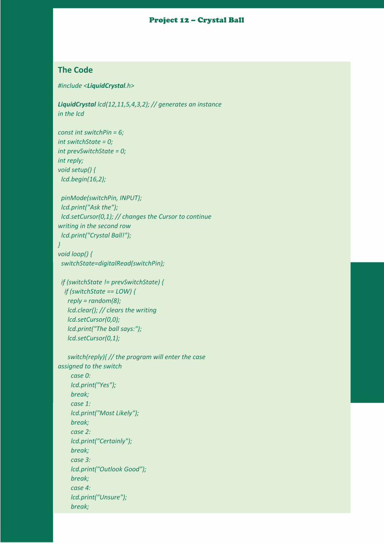
84
Project 12 – Crystal Ball
The Code
#include <LiquidCrystal.h>
LiquidCrystal lcd(12,11,5,4,3,2); // generates an instance
in the lcd
const int switchPin = 6;
int switchState = 0;
int prevSwitchState = 0;
int reply;
void setup()
lcd.begin(16,2);
pinMode(switchPin, INPUT);
lcd.print("Ask the");
lcd.setCursor(0,1); // changes the Cursor to continue
writing in the second row
lcd.print("Crystal Ball!");
void loop()
switchState=digitalRead(switchPin);
if (switchState != prevSwitchState)
if (switchState == LOW)
reply = random(8);
lcd.clear(); // clears the writing
lcd.setCursor(0,0);
lcd.print("The ball says:");
lcd.setCursor(0,1);
switch(reply) // the program will enter the case
assigned to the switch
case 0:
lcd.print("Yes");
break;
case 1:
lcd.print("Most Likely");
break;
case 2:
lcd.print("Certainly");
break;
case 3:
lcd.print("Outlook Good");
break;
case 4:
lcd.print("Unsure");
break;
case 5:
lcd.print("Pregunta de nuevo");

85
Project 12 – Crystal Ball
The Code
case 5:
lcd.print("Ask again");
break;
case 6:
lcd.print("Doubtful");
break;
case 7:
lcd.print("No");
break;
prevSwitchState = switchState;
The Code
To use the magic ball, power the Arduino. Check the screen to make sure it says “Ask the
Crystal ball!” If you can’t see the characters, try turning the potentiometer. It will adjust the
contrast of the screen.
Ask a question of your crystal ball, and try tilting the switch up-side down and back again. You
should get an answer to your question. If the answer doesn’t suit you, ask again.
Try adding your own sayings to the print() statements, but be mindful of the fact that there are only
16 characters to use per line. You can also try adding more responses. Make sure when you add
additional switch cases, you adjust the number of options that will randomly populate the reply
variable.
LCDs work by changing the electrical properties of a liquid sandwiched between polarized glass.
The glass only allows certain kinds of light to pass through. When the liquid between the glass is
charged, it starts to form into a semi-solid state. This new state runs in a different direction than
the polarized glass, blocking light from passing through, thus creating the characters you see on the
screen.

86
Project 12 – Crystal Ball
We are now at the end of
today’s class. Please do not
hesitate to ask your tutor for
help or check online for more
information. See you in the next
class.

87
Project 13 – Welcome back to
YouNiversity
Hello Class! Welcome back to YouNiversity! Just like you did
in the last YouNiversity, once again:
Go to YouTube
Find an Arduino project
Follow how it was built and build it
Then, present your project to your friends explaining to
them why you selected the project, what you have
learnt, and how others can learn from the project.

88
Project 13 – Welcome back to
YouNiversity
We are now at the end of our Arduino class. Please
make sure you keep working on the projects, look
for new projects to develop, and to forget to keep
sharing your result with your friends. If you need
any further assistance, do not hesitate to ask your
tutor for help or check online for more information.
I wish you a bright, prosperous and productive
future!