cas gps user manual - fcc id · cas gps user manual.docx rev is on: e1 page 3 of 30 cas gps user...
TRANSCRIPT

CAS GPS
Collision Avoidance System
User Manual
Rev E1
GE Mining Industrea Mining Technology
PO Box 5107 Fountaindale, New South Wales
Australia, 2258 t +61 2 4336 1800 f +61 2 4336 1888
e [email protected] w www.ge.com/au

CAS GPS User Manual.docx Revision: E1 Page 2 of 30
CAS GPS User Manual
Table of Contents 1 Document Revision ............................................................................................................................................................................................... 3 2 Copyright Notice .................................................................................................................................................................................................... 3 3 Disclaimer ................................................................................................................................................................................................................. 3 4 Warnings ................................................................................................................................................................................................................... 3 5 Company Details ................................................................................................................................................................................................... 3 6 Scope .......................................................................................................................................................................................................................... 4
6.1 Abbreviations .............................................................................................................................................................................................. 4 6.2 Definitions ..................................................................................................................................................................................................... 4
7 Transport................................................................................................................................................................................................................... 4 8 Storage....................................................................................................................................................................................................................... 4 9 Unpacking of Equipment .................................................................................................................................................................................... 4 10 Installation ................................................................................................................................................................................................................ 4 11 Test & Commission ............................................................................................................................................................................................... 4 12 Operation .................................................................................................................................................................................................................. 5
12.1 Principle of Operation .............................................................................................................................................................................. 5 12.2 Object Types ................................................................................................................................................................................................ 7 12.3 Key Components ........................................................................................................................................................................................ 8
12.3.1 Display Unit ....................................................................................................................................................................................... 8 12.3.2 In Vehicle Unit (IVU) ...................................................................................................................................................................... 17
12.4 System Interconnections ...................................................................................................................................................................... 18 13 Service, Maintenance & Disposal ...................................................................................................................................................................... 21
13.1 Equipment Service ................................................................................................................................................................................... 21 13.1.1 Display Unit .......................................................................................................................................................................................... 21 13.1.2 System ................................................................................................................................................................................................... 21 13.1.3 Scheduled System Servicing ........................................................................................................................................................ 21 13.1.4 Software Updates ............................................................................................................................................................................. 21 13.2 Equipment Maintenance .................................................................................................................................................................. 21
14 Troubleshooting ................................................................................................................................................................................................... 22 14.1 No power / blank screen ...................................................................................................................................................................... 22 14.2 GPS Problems ............................................................................................................................................................................................ 23 14.3 V2V Problems ............................................................................................................................................................................................ 24 14.4 WiFi/GSM Problems ................................................................................................................................................................................ 25
15 Decommission ...................................................................................................................................................................................................... 26 16 Disposal ................................................................................................................................................................................................................... 26 17 Specifications ........................................................................................................................................................................................................ 27 18 Authorized Representatives ............................................................................................................................................................................ 28
18.1 - Brazil ................................................................................................................................................................................................................. 28 18.2 - South Africa.................................................................................................................................................................................................... 28 18.3 - Indonesia......................................................................................................................................................................................................... 28 18.4 – Canada ............................................................................................................................................................................................................ 28 18.5 – North America .............................................................................................................................................................................................. 28 18.6 – Australia .......................................................................................................................................................................................................... 28
19 Warranty Terms ................................................................................................................................................................................................... 29 20 Regulatory Information ..................................................................................................................................................................................... 29
FEDERAL COMMUNICATIONS COMMISSION Part 15 Compliant ........................................................................................................... 29 FCC Interference Statement for Class B devices. .................................................................................................................................. 29 Federal Communication Commission (FCC) - Radiation Exposure Statement ......................................................................... 29
INDUSTRY CANADA Compliant ........................................................................................................................................................................... 29 Concerning Radio Transmitters .................................................................................................................................................................... 29 Detachable Antennas ........................................................................................................................................................................................ 29 Industry Canada - Radiation Exposure Statement ............................................................................................................................... 30
Australian Radio Communications Equipment - Radiation Exposure Statement ........................................................................ 30 Anatel Resolution 506 Statement...................................................................................................................................................................... 30

CAS GPS User Manual.docx Revision: E1 Page 3 of 30
CAS GPS User Manual
1 Document Revision REV DESCRIPTION Author Review Approval Date
Draft
Draft Release
SW
28/11/13
A
First Release
SW
CH
CH
28/11/13
B
Addition of RF functionality
SW
TW
TW
14/03/14
C
Additional of operator screens
TW
CH
TW
24/07/14
D
Update product name, Add 868MHz Specs
NM
CH
TW
17/12/14
E
Update Compliance Information / Format Images
NM
17/02/16
2 Copyright Notice No part of this publication may be reproduced, transmitted or transcribed into any language by any means without the express written permission of Industrea Mining Technology Pty Ltd.
3 Disclaimer These materials are provided for information purposes only, "as is," without express or implied warranty of any kind. GE makes no ANY EXPRESS OR IMPLIED WARRANTY OF MERCHANTABILITY OR OF FITNESS FOR A PARTICULAR PURPOSE OR ANY OTHER EXPRESS OR IMPLIED WARRANTY REGARDING ANY PRODUCTS DESCRIBED in these materials. To the maximum extent permitted by law, GE disclaims any and all implied warranties that might otherwise arise or apply, including any implied warranty of merchantability or of fitness for a particular purpose. GE further makes no representation or warranty of accuracy of these materials and neither GE will have no responsibility or liability for any error or omission in these materials.
4 Warnings • The CAS product is a driver’s aid and should not be relied upon as the primary means of reducing
the risks of high potential interactions between Heavy Vehicles, Light Vehicles, infrastructure and personnel.
• GPS based proximity detection may not operate when satellites are not fully visible in the sky (e.g. in a deep mining pit near a high-wall or under a workshop roof). Consideration should be given to supplementing GPS with RF proximity detection and visual aids using cameras.
• Alarm logic should be determined via site specific risk assessment based on the end-users specified high risk interactions.
• The CAS product does not take control of the vehicle although can provide inhibit signals to prevent movement from a stationary position – implementation will require approval from the vehicle OEM, vehicle owner and GE and a detailed risk assessment conducted.
5 Company Details
Industrea Mining Technology PO Box 5107 Chittaway Bay NSW 2258 3 Co-Wyn Close, Fountaindale, NSW 2258 Australia Industrea Mining Technology T +61 243 361 800 F +61 243 892 355 E [email protected] W www.ge.com/au

CAS GPS User Manual.docx Revision: E1 Page 4 of 30
CAS GPS User Manual
6 Scope CAS GPS User Manual
This user manual covers the following variants of the CAS GPS system (defined by the IVU features):
• PROD0841-x LAN CAS In Vehicle Unit (IVU) • PROD0842-x WIFI/LAN CAS In Vehicle Unit (IVU) • PROD0843-x GSM/LAN CAS In Vehicle Unit (IVU) • PROD0847-x GSM/WIFI/LAN CAS In Vehicle Unit (IVU)
6.1 Abbreviations Abbreviation Meaning IVU In Vehicle Unit GPS Global Positioning System CAS Collision Avoidance System LAN Local Area Network Wi-Fi Wireless Communication Medium GSM Global System for Mobile Communications OEM Original Equipment Manufacture
6.2 Definitions
Term Definition “system” Refers to the assembled and installed operational elements which together perform
the desired functionality. “system components” Refers to the individual single elements which when assembled together at the
point of installation form the “system”. Each of these elements has a unique part number.
7 Transport All possible precautions are taken to protect the equipment against damage or losses during shipment, however before accepting delivery, check all items against the packing list or Bill of Lading. If there are shortages or evidence of physical damage, notify GE Mining immediately.
Notify GE Mining within 7 days (maximum) in case of shortages or discrepancies, according to the packing list. This action will help ensure a speedy resolution to any perceived problems. Keep a record of all claims and correspondence. Photographs are recommended.
Where practicable do not remove protective covers prior to installation unless there are indications of damage. Boxes opened for inspection and inventory should be carefully repacked to ensure protection of the contents or else the parts should be packaged and stored in a safe place. Examine all packing boxes, wrappings and covers for items attached to them, especially if the wrappings are to be discarded.
8 Storage Where the equipment is not to be installed immediately, proper storage is important to ensure protection of equipment and validity of warranty.
All equipment should be stored indoors protected from the elements in a cool dry area. If storing on the ground, ensure that the storage area is not an area where water will collect.
9 Unpacking of Equipment The method of packing used will depend on the size and quantity of equipment. Take care when unpacking the equipment to avoid damage.
10 Installation Installation should be in accordance with the installation procedures defined by GE Mining and only performed by authorized and qualified installers.
11 Test & Commission At installation the system will be tested to ensure that electrically and functionally the system is correctly installed After passing its final installation test, the system is then ready for use after which inbuilt self- diagnostic testing combined with daily user monitoring ensures that any faults can be acted upon

CAS GPS User Manual.docx Revision: E1 Page 5 of 30
CAS GPS User Manual
12 Operation 12.1 Principle of Operation
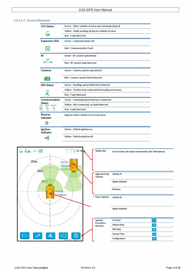
The CAS GPS product is designed to offer a situational awareness driver aid utilising GPS proximity detection of vehicles/objects and data logging. Each vehicle broadcasts its current position and relevant parameters which are used to detect warnings of possible intersections with other vehicles that receive the broadcast. The position of other vehicles, together with any warnings is shown graphically on the Display Unit.
The system aids the driver with a continuous view of other objects that are moving, stationary, over the horizon, just behind the vehicle or simply out of sight due to bad visibility when operating their vehicle. The system is designed to avoid distracting the driver from driving, but provides the driver with an awareness tool to notify and visualise other objects surrounding the vehicle on take-off and during operation.
The CAS-GPS system notifies the driver with progressive audible and graphic alerts as shown in the table below. The system continually broadcasts its location and receives broadcasts of other vehicles in radio communications for up to 500 meters using the in-built proprietary radio link. Vehicle interactions are projected based on the trajectories of the vehicles; an alert is triggered and depending on the configuration, an acknowledgement by the driver on the touch screen may be required (only when the vehicle is stationary).

CAS GPS User Manual.docx Revision: E1 Page 6 of 30
CAS GPS User Manual
Positional Tracking The system uses the latest precision point GPS technology which gives accurate location-based tracking. The accuracy of the GPS is backed up by an advanced array of tracking aiding multidimensional G-Force and Gyro digital sensors. The tracking aiding digital sensors assist the GPS position fix when the GPS signal is inhibited resulting in accurate positions even with no view of the sky.
Data Logging The IVU continuously logs all parameters and objects in view to a local database every second (black box technology). The IVU retains 30 days of the 1 second logs. The database captures every 1 second the engine parameters, the vehicle dynamics and other vehicles in view. The local IVU database allows the site manager to retrieve all of the events in a desired date range to gain access to more detail of a specific event.
Connectivity The IVU has the ability to upload event logs from its internal database in real-time or upload all data from within a selected date range including the detailed 1 second system-wide logs. The event logs can be transmitted to the central server’s database via the following connections.
• Wi-Fi • Ethernet, • GPRS GSM, 3G, HSDPA and in future models the 4G LTE network.
The event logs can be retrieved manually from the removable flash card if there is no connectivity available from the IVU. The data can then be transferred into the central server’s database for reporting and analysis.

CAS GPS User Manual.docx Revision: E1 Page 7 of 30
CAS GPS User Manual
12.2 Object Types These icons are used on the display to represent the various vehicle types:

CAS GPS User Manual.docx Revision: E1 Page 8 of 30
CAS GPS User Manual
12.3 Key Components
12.3.1 Display Unit
CAS GPS User Manual.docx Revision: E1 Page 9 of 30
CAS GPS User Manual
12.3.1.1 Screen Elements

CAS GPS User Manual.docx Revision: E1 Page 10 of 30
CAS GPS User Manual
12.3.1.2 List View
Pressing the button toggles the object list view on or off

CAS GPS User Manual.docx Revision: E1 Page 11 of 30
CAS GPS User Manual
12.3.1.3 GPS Status view
Pressing the button will present the operator with the GPS status screen. The GPS Status screen holds all of the crucial data that is currently available from the GPS in real time. Pressing the GPS button again will turn off this screen and if the heading is not valid, the list view will be presented otherwise the screen will have the GPS status screen removed.

CAS GPS User Manual.docx Revision: E1 Page 12 of 30
CAS GPS User Manual
12.3.1.4 User Settings View
Pressing the button turns the user settings screen on. The user settings screen allows the operator to adjust the brightness of the screen from minimum to maximum settings using the slide bar. On automatic change of day and night mode, the brightness is changed to the default day and night values and the operator selected brightness will be overridden. Also on a restart of the system, the brightness will default back to the default day and night settings. The operator can change the current brightness settings at any time.

CAS GPS User Manual.docx Revision: E1 Page 13 of 30
CAS GPS User Manual
12.3.1.5 Camera View
Pressing the button turns on the camera view.
Pressing the button closes the camera view
The camera view will automatically close when the vehicle travels faster than the preconfigured camera off speed (default 10km/h).

CAS GPS User Manual.docx Revision: E1 Page 14 of 30
CAS GPS User Manual
12.3.1.6 Camera Selection
Once the camera view has been enabled cameras may be selected by pressing anywhere in the relevant quadrant as shown in the diagram below:

CAS GPS User Manual.docx Revision: E1 Page 15 of 30
CAS GPS User Manual
12.3.1.7 RF Detections
The CAS GPS system can optionally be fitted with additional RF proximity detection unit(s). This may be the case if the site wants additional redundancy in the system or commonly when sites update their existing CAS-CAM/RF systems.
The following example shows a truck travelling forward at 6km/h with the Front camera selected. As a vehicle fitted with RF detectors (only) approaches from the RHS the Right camera will automatically be selected and the quadrant highlighted to indicate a vehicle is within the preconfigured distance (30m in this example). Note no icon is presented on the screen but the vehicles ID appears in the table (no speed or distance is displayed).

CAS GPS User Manual.docx Revision: E1 Page 16 of 30
CAS GPS User Manual
12.3.1.8 Using the Display
On Vehicle Start-up Immediately after starting the vehicle and before putting it into motion; perform a quick check of the Display’s status bar. Check that none of the icons are Red, if so your CAS GPS system is not functioning correctly and its operation cannot be assured!
Before engaging gear (and in addition to your normal safety procedures), use the Display to gain further awareness of other nearby CAS GPS equipped vehicles. These vehicles will be displayed as icons on your screen each representing their type of vehicle, vehicle ID, speed, distance and direction of travel.
If a nearby vehicle’s beams are overlapping your vehicles beam an audible alarm will be sounded. Only when your vehicle is stationary may you silence the alarm by touching anywhere on the screen.
Vehicle in Motion When your vehicle is moving you can operate using your normal safe operating procedures. The Display will sound an alarm to gain your attention if there is another vehicle that is getting too close. A quick glance at the display will show the location, type, ID, heading and speed of other vehicles. You cannot silence the alarm while your vehicle is moving!
Night Operations A light sensor in the Display will put the screen into Night Mode when the ambient light level drops below a preconfigured level. In night mode the screen will change from a white to a black background, this keeps the brightness down so that the screen will not become a distraction during night operations.
Daytime Operations A light sensor in the Display will put the screen into Daytime Mode when the ambient light level rises above a preconfigured level. In Daytime mode the screen will change from a black to a white background, this makes the information displayed on the screen easy to read in high ambient light levels.
CAS GPS User Manual.docx Revision: E1 Page 17 of 30
CAS GPS User Manual
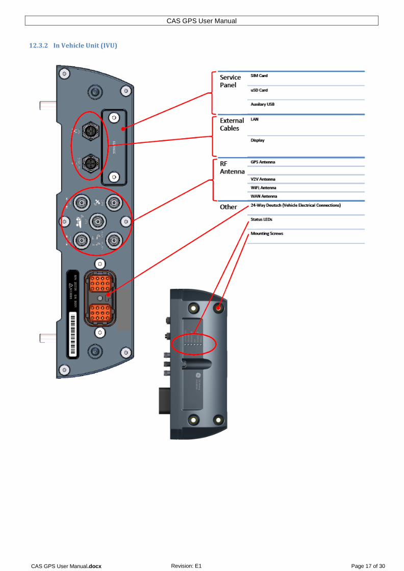
12.3.2 In Vehicle Unit (IVU)

CAS GPS User Manual.docx Revision: E1 Page 18 of 30
CAS GPS User Manual
12.4 System Interconnections
The main system components and their connections are shown below:

CAS GPS User Manual.docx Revision: E1 Page 19 of 30
CAS GPS User Manual
12.4.1.1 CAS-CAM/RF interconnections (1CAM/1RF)

CAS GPS User Manual.docx Revision: E1 Page 20 of 30
CAS GPS User Manual
12.4.1.2 CAS-CAM/RF interconnections (4CAM/4RF)

CAS GPS User Manual.docx Revision: E1 Page 21 of 30
CAS GPS User Manual
13 Service, Maintenance & Disposal 13.1 Equipment Service
13.1.1 Display Unit • Clean screen surface with a clean dry soft cloth - Do not use solvents or cleaners on the screen
surface! • Check for physical damage to screen surface • Check the cable connector is securely connected at the rear of the screen – finger tighten only if
loose • Check the mounting bracket is secure – finger tighten only if loose
13.1.2 System • Check visually that all antennas are in good condition and the antenna cables are connected • Check visually that no cables are loose or damaged • Verify that the system is working correctly prior to starting the vehicle and during operations
13.1.3 Scheduled System Servicing It is recommended that the system undergo preventative scheduled maintenance and inspections. These should be carried out by trained and authorized personnel every 6 month or 1500hrs (whichever occurs first).
13.1.4 Software Updates Software updates are automatically pushed out to all IVUs connected to the CAS server.
13.2 Equipment Maintenance If the system is not functioning as expected, refer to section 14 Troubleshooting. If a fault cannot be resolved, please contact your nearest authorized representative.
It is essential that no attempt be made to repair the equipment (other than replacement of individual components). Opening equipment enclosures should never be attempted and will void any warranty and could compromise the safe operation of the system.

CAS GPS User Manual.docx Revision: E1 Page 22 of 30
CAS GPS User Manual
14 Troubleshooting 14.1 No power / blank screen
Use this flow diagram to troubleshoot an apparent loss of power or blank screen:

CAS GPS User Manual.docx Revision: E1 Page 23 of 30
CAS GPS User Manual
14.2 GPS Problems
The GPS signal status is indicated by the colour of the icon at the top of the display.
• Green – Position and Heading fix – no faults • Yellow – Position fix but no heading – no faults • Red – No GPS signal or GPS error – fault or no signal detected

CAS GPS User Manual.docx Revision: E1 Page 24 of 30
CAS GPS User Manual
14.3 V2V Problems
The Vehicle to Vehicle communication status is indicated by the colour of the icon at the top of the display.
• Green – Communicating with other vehicles – no faults • Yellow – No other vehicles in range – no faults • Red – Radio error – fault or error detected

CAS GPS User Manual.docx Revision: E1 Page 25 of 30
CAS GPS User Manual
14.4 WiFi/GSM Problems
The Wi-Fi or GSM communication status is indicated by the colour of the or icons at the top of the display.
• Green – Connected to the network – no fault • Red – No signal or fault/error detected

CAS GPS User Manual.docx Revision: E1 Page 26 of 30
CAS GPS User Manual
15 Decommission • Removal of the system should only be performed if authorized by the owner of the vehicle • Removal should be performed by a qualified Auto Electrician • All system components and wiring should be removed • All vehicle wiring should be restored back to original condition • Dispose or store removed system in accordance with this manual
16 Disposal
The electronic equipment discussed in this manual must not be treated as general waste. By ensuring that this product is disposed of correctly, you will be helping to prevent potentially negative consequences for the environment and human health which could otherwise be caused by incorrect waste handling of this product.
The system should be disposed of in accordance with local regulations. The electronics of CAS GPS are ROHS compliant. The system contains a Lithium Ion Battery and should be disposed of in accordance with local regulations.

CAS GPS User Manual.docx Revision: E1 Page 27 of 30
CAS GPS User Manual
17 Specifications
International Approvals
Australia
ACMA RCM (PROD0841-2) (PROD0842-2) + WiFi (PROD0843-2) + GSM (PROD0847-2) + WiFi & GSM
North America
FCC (PROD0841-2) FCC ID: YIY-PROD08422 (PROD0842-2) FCC ID: YIY-PROD08422 (PROD0843-2) FCC ID: YIY-PROD08472 (PROD0847-2) FCC ID: YIY-PROD08472
Brazil ANATEL 3973-13-1486 (PROD0841-2) (PROD0842-2)
Indonesia
POSTEL 34481/SDPPI/2014 PLG ID: 3944 (PROD0841-2) (PROD0842-2)
Canada
INDUSTRY CANADA (PROD0841-2) IC: 8903A-PROD08422 (PROD0842-2) IC: 8903A-PROD08422 (PROD0843-2) IC: 8903A-PROD08472 (PROD0847-2) IC: 8903A-PROD08472
South Africa
ICASA TA-2015/074 (PROD0841-1) (PROD0842-1) (PROD0843-1) (PROD0847-1)
Environmental Performance Storage Temp. -30°C to +85°C
Vibration Withstands 3.5mm at 5-18.7Hz, 5g at 18.7-150Hz
Shock Withstands 15g ½ sine 10ms on each axis, bi- directional on all 3 axes
Power Requirements Input Voltage 9-36VDC
Typical power consumption for 24/12V input.
0.01A for IVU standby & V2V powered by internal battery
0.5/1.0A for IVU & display
0.8/1.6A for IVU & display & 1 camera & 2 TOF
1.2/2.4A for IVU & display & 4 camera & 4 TOF (+ 0.2/0.4A when charging backup battery)
Display Unit Type Capacitive touchscreen
Dimensions 133 wide x 223 high x 25mm deep (basic) 57mm deep (with ball)
Weight 810g
IP Rating IP52
Operating Temp. -10°C to +60°C
Mounting 1” Ball (RAM Mount)
Power From IVU
Screen size 7”
Screen Resolution 1024 x 600 WSVGA
Inputs From IVU via M12 connector
Microphone yes
Buzzer 78dB at 50cm
Speakers 2x1W, programmable up to 81dB at 50cm
In Vehicle Unit (IVU) Dimensions 290 wide x 72 high x 130mm deep (basic)
Weight 2060g
IP Rating IP66
Operating Temp. -15°C to +60°C
Mounting holes Footprint 215x48mm (suits 4 x M8 SHCS)
Typical battery backup
14hrs standby operation (GPS+V2V active).
3hrs charge time
Battery type LiFePO4, 3.7V, 3200mAh, UN38.3 Certification
Main CPU Standby CPU
ARM 32-bit Cortex™ A8, 800MHz
ARM 32-bit Cortex™ M3
Memory Card Micro SD
RAM 1Gb DDR3
Sensors
3-axis gyroscope
3-axis accelerometer
3-axis magnetometer
Altimeter -500m to 9000m
Main interface Deutsch DRC series 24-pin connector
12V DC Output 1 x 12VDC @ 1.2A Max
Digital Output 2 x SPST (wet contact) Vin @ 250mA Max
Digital Inputs 2 x dry 2.5kV isolated
2 x wet Common Ground (60Vdc Tolerant @30mA)
CAN interface J1939 support
USB interface 2 x USB2.0
LAN interface 1 x 10BASE-T / 100BASE-TX
Other interface 2 x RS232/485 configurable
Video input 1 x differential
RF connectors TNC
V2V Radio PROD084x-2
965 kHz 6dB RF bandwidth.
920 MHz Digital radio.
100 mW transmit power. 1000 kbps data rate. (500 kHz symbol rate, 2 bits/ symbol), Single channel, 4GFSK Modulation (4 Gaussian Frequency Shift Keying, 125 kHz inner deviation). 960 bits per packet (490 symbols). 980 μs packet duration. 320 ms packet repetition period. Duty cycle < 1%. (0.3%).
Range up to 500m
3 dBi nominal antenna gain (< 6dBi). Pre-terminated cable to dedicated antenna mount.
GPS
Multi-GNSS. GPS, GLONASS, Galileo and QZSS compatible.
Horizontal accuracy ± 2.5m *
* (CEP, 50%, 24 hours static, -130 dBm, > 6 SVs)
Mobile communications (optional)
UMTS WCDMA/HSDPA/HSUPA/HSPA+. 800 MHz, 850 MHz, 900 MHz, 1800 MHz, 1900MHz, 2100 MHz
GSM, GPRS, EDGE.
WIFI (optional) IEEE 802.11 b/g/n
TOF proximity ranging (optional)
2.4GHz IEEE 802.15.4a
0-250m, ±2m accuracy

CAS GPS User Manual.docx Revision: E1 Page 28 of 30
CAS GPS User Manual
Reference Standards IEC 60529 Degrees of protection provided by enclosures (IP Code) ETSI EN 300 220 RF Performance Characteristics (V2V)
IEC 60068-2-6 Vibration ETSI EN 300 328 RF Performance Characteristics (Wi-Fi)
IEC 60068-2-27 Shock ETSI EN 300 440 RF Performance Characteristics (GPS)
IEC 61000-4-2 Electrostatic Discharge ETSI EN 301 511 RF Performance Characteristics (GSM)
EN 61000-4-3 Immunity to Radiated Electromagnetic Field ETSI EN 301 908 RF Performance Characteristics (3G)
IEC 61000-4-4 Electrical Fast Transient / Burst (EFT) EN 60950 -1 Electrical Safety
IEC 61000-4-5 Surge Immunity AS/NZS 4268 Radio-Communications Limits (RSE)
EN 61000-4-6 Immunity to Conducted Disturbances FCC 47 PART 15A&B Electromagnetic Compatibility Class B (EMC)
ISO 7637-2 Automotive Electrical Disturbances FCC 47 PART 15C Radio-Communications Limits (RSE)
ETSI EN 301 489 Electromagnetic Compatibility (EMC / EMI) (Parts 1, 3, 7, 17, 24) ICES-003 Electromagnetic Compatibility Class B (EMC)
EN 55022 (CISPR22) Electromagnetic Compatibility Class B (EMC) RSS-247 Radio-Communications Limits (RSE)
RSS-102 Electromagnetic Radiation
18 Authorized Representatives 18.1 - Brazil 18.2 - South Africa
Avenida Portugal 4511/Bairro Itapoa Belo Horizonte, M.G. 31710-400, Brazil P: +55 31 3311 7200 F: +55 31 3311 7205 Email: [email protected] www.joyglobal.com
Probe CAMS 245 Albert Amon Road Meadowdale Germiston 1614 P: +27 11 453 0924 F: +27 11 453 2141 www.probebattery.co.za
18.3 - Indonesia 18.4 – Canada
PT Intecs Teknikatama Industri Jl. Ciputat Raya No. 18D Kebayoran Lama Selatan Jakarta 12240 . P: +62 21 729 3351 F: +62 21 729 3352 www.intecs.co.id
General Electric Canada 2300 Meadowvale Blvd, Mississauga, ON, L5N 5P9 P: 1-800-561-3344 P: +1 905-858-5100 www.ge.com
18.5 – North America 18.6 – Australia
General Electric Company, Mining 2901 East Lake Road, Erie, Pennsylvania, 16531, US P: 480 264-2063 F: 480 264-6402 www.getransportation.com
GE Mining, Industrea Mining Technology 3 Co-Wyn Close, Fountaindale, NSW, 2258, Australia P: +612 4336 1800 F: +612 4389 2355 www.getransportation.com

CAS GPS User Manual.docx Revision: E1 Page 29 of 30
CAS GPS User Manual
19 Warranty Terms
Equipment and Parts: 15 months from delivery, or 12 months from when system is placed in service (whichever occurs first). Modifications to this product without written consent from the manufacturer or its designated authorised representatives will void all warranty obligations.
20 Regulatory Information
Compliance markings of the CAS-GPS are available via the service Information menu of the system display.
FEDERAL COMMUNICATIONS COMMISSION Part 15 Compliant CAUTION: This device complies with part 15 of the FCC Rules. Operation is subject to the following two conditions: (1) This device may not cause harmful interference, and (2) This device must accept any interference received, including interference that may cause undesired operation. Changes or modifications not expressly approved by the party responsible for compliance could void the user's authority to operate the equipment.
FCC Interference Statement for Class B devices. This equipment has been tested and found to comply with the limits for a Class B digital device, pursuant to part 15 of the FCC Rules. These limits are designed to provide reasonable protection against harmful interference in a residential installation. This equipment generates, uses and can radiate radio frequency energy and, if not installed and used in accordance with the instructions, may cause harmful interference to radio communications. However, there is no guarantee that interference will not occur in a particular installation. If this equipment does cause harmful interference to radio or television reception, which can be determined by turning the equipment off and on, the user is encouraged to try to correct the interference by one or more of the following measures: —Reorient or relocate the receiving antenna. —Increase the separation between the equipment and receiver. —Connect the equipment into an outlet on a circuit different from that to which the receiver is connected. —Consult the dealer or an experienced radio/TV technician for help. WARNING: A shielded type Ethernet cord is required to meet FCC Class B emission limits and also prevent interference to the nearby radio and television reception. This device and its antenna(s) must not be co-located or operate in conjunction with any other antenna or transmitter. The antenna is considered an integral system component. Use of any antenna other than those specified in the installation manual or supplied with the product may void the product’s compliance.
Federal Communication Commission (FCC) - Radiation Exposure Statement To comply with FCC RF exposure limits for general population / uncontrolled exposure, the antennas used for this transmitter must be installed to provide a separation distance of at least 20 cm from all persons and must not be co-located or operating in conjunction with any other antenna or transmitter. INDUSTRY CANADA Compliant This Class B digital apparatus complies with Canadian ICES-003. Changes or modifications not expressly approved by the party responsible for compliance could void the user’s authority to operate the equipment.
Concerning Radio Transmitters This device complies with Industry Canada’s licence-exempt RSSs. Operation is subject to the following two conditions:
(1) This device may not cause interference; and (2) This device must accept any interference, including that may cause undesired operation of the device.
Under Industry Canada regulations, this radio transmitter may only operate using an antenna of a type and maximum (or lesser) gain approved for the transmitter by Industry Canada. To reduce potential radio interference to other users, the antenna type and its gain should be so chosen that the equivalent isotropically radiated power (e.i.r.p.) is not more than that necessary for successful communication
Detachable Antennas This radio transmitter has been approved by Industry Canada to operate with the antenna types listed in the installation manual with the maximum permissible gain and required antenna impedance for each antenna type indicated. Antenna types not included in this list, having a gain greater than the maximum gain indicated for that type, are strictly prohibited for use with this device.

CAS GPS User Manual.docx Revision: E1 Page 30 of 30
CAS GPS User Manual
Industry Canada - Radiation Exposure Statement To comply with Industry Canada RF exposure limits for general population / uncontrolled exposure, the antennas used for this transmitter must be installed to provide a separation distance of at least 25 cm for GSM product variants or 20cm for non GSM product variants from all persons and must not be co-located or operating in conjunction with any other antenna or transmitter.
Industrie Canada – Déclaration sur l’exposition aux radiations Afin de respecter les limites d’exposition pour l’ensemble de la population/l’exposition non contrôlée de la FCC/IC RF, les antennes utilisées pour cet émetteur doivent être installées de manière à offrir une distance de séparation minimum de 25 cm pour les variantes de produits GSM ou de 20 cm pour les variantes de produits non GSM de toutes les personnes et ne doivent pas être utilisées en conjonction avec d’autres antennes ou émetteurs.
Conforme aux normes d’INDUSTRIE CANADA Cet appareil numérique de classe B est conforme à la norme canadienne ICES-003. Les changements ou les modifications non approuvés expressément par la partie responsable de la conformité pourraient annuler l’autorisation de l’utilisateur de faire fonctionner l’équipement.
Au sujet des émetteurs radio Cet appareil respecte les systèmes de satellite de radiodiffusion d’Industrie Canada. Son fonctionnement est soumis aux deux conditions suivantes :
(1) Cet appareil ne peut pas causer de l’interférence; et (2) Cet appareil doit accepter toute interférence, y compris celle qui provoque un fonctionnement non souhaité
de l’appareil.
Conformément aux règlements d’Industrie Canada, cet émetteur radio peut fonctionner uniquement au moyen d’une antenne de type et avec un gain maximal (ou plus petit) approuvés pour l’émetteur par Industrie Canada. Afin de réduire la possible interférence radio avec les autres utilisateurs, le type d’antenne et son gain devraient être choisis de manière à ce que la puissance isotrope rayonnée équivalente (p.i.r.e.) ne soit pas plus grande que nécessaire pour une communication réussie.
Antennes détachables Cet émetteur radio a été approuvé par Industrie Canada pour fonctionner avec les types d’antennes inscrites dans le manuel d’installation avec le gain maximum permis et l’impédance d’antenne requise pour chaque type d’antenne indiqué. Les types d’antennes non compris dans la liste, qui ont un gain supérieur au gain maximum indiqué pour le type en question, sont strictement interdits.
Australian Radio Communications Equipment - Radiation Exposure Statement The equipment complies with the Radiocommunications (Electromagnetic Radiation – Human Exposure) Standard 2014 for General Public Exposure, Non-Aware User, for a Compliance Level 2 Radiocommunications Equipment, when the minimum safety distance of 36cm is adhered to, and shall bear the RCM. Anatel Resolution 506 Statement This equipment operates in a secondary manner, that is, does not have the right of protection against prejudicial interference, even from stations of the same type, and nor can they cause interference to systems operating in a primary manner.