cascade hc/hfc - co2 system how to control the...
TRANSCRIPT
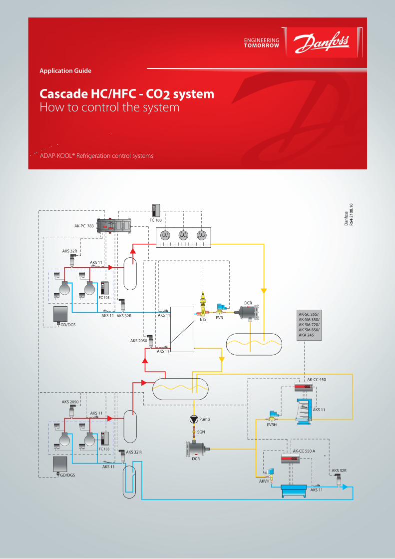
Cascade HC/HFC - CO2 systemHow to control the system
Application Guide
ADAP-KOOL® Refrigeration control systems
AKS 32 R
AKS 32R
GD/DGS
AKS 11
AKS 2050
AKS 11
GD/DGS
AKS 11
AKS 32R
FC 103
AKS 11
DCR
Pump
SGN
AKS 2050
AKS 11
EVRETS
DCR
FC 103
FC 103
AK-CC 450
AKS 11
AK-CC 550 A
AKS 11
AK-PC 783 Dan
foss
R64-
2108
.10
AKS 32R
AK-SC 355/AK-SM 350/AK-SM 720/AK-SM 850/AKA 245
AKS 11
EVRH
AKVH
2 Application guide RA8AB202 © Danfoss 5/2013 Cascade HC/HFC - CO2 system
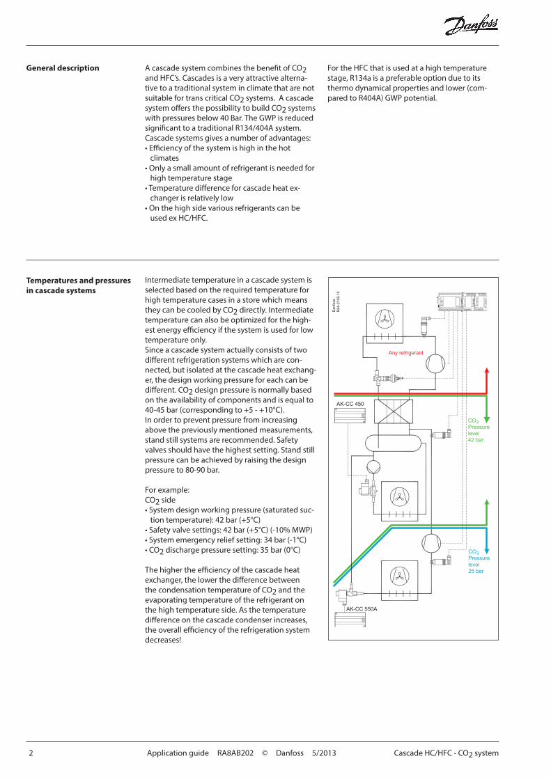
Intermediate temperature in a cascade system is selected based on the required temperature for high temperature cases in a store which means they can be cooled by CO2 directly. Intermediate temperature can also be optimized for the high-est energy efficiency if the system is used for low temperature only. Since a cascade system actually consists of two different refrigeration systems which are con-nected, but isolated at the cascade heat exchang-er, the design working pressure for each can be different. CO2 design pressure is normally based on the availability of components and is equal to 40-45 bar (corresponding to +5 - +10°C). In order to prevent pressure from increasing above the previously mentioned measurements, stand still systems are recommended. Safety valves should have the highest setting. Stand still pressure can be achieved by raising the design pressure to 80-90 bar.
For example:CO2 side• System design working pressure (saturated suc-
tion temperature): 42 bar (+5°C)• Safety valve settings: 42 bar (+5°C) (-10% MWP)• System emergency relief setting: 34 bar (-1°C)• CO2 discharge pressure setting: 35 bar (0°C)
The higher the efficiency of the cascade heat exchanger, the lower the difference between the condensation temperature of CO2 and the evaporating temperature of the refrigerant on the high temperature side. As the temperature difference on the cascade condenser increases, the overall efficiency of the refrigeration system decreases!
General description
Temperatures and pressures in cascade systems
For the HFC that is used at a high temperature stage, R134a is a preferable option due to its thermo dynamical properties and lower (com-pared to R404A) GWP potential.
A cascade system combines the benefit of CO2 and HFC’s. Cascades is a very attractive alterna-tive to a traditional system in climate that are not suitable for trans critical CO2 systems. A cascade system offers the possibility to build CO2 systems with pressures below 40 Bar. The GWP is reduced significant to a traditional R134/404A system. Cascade systems gives a number of advantages:• Efficiency of the system is high in the hot
climates• Only a small amount of refrigerant is needed for
high temperature stage • Temperature difference for cascade heat ex-
changer is relatively low• On the high side various refrigerants can be
used ex HC/HFC.
AK-CC 550A
AK-CC 450
Dan
foss
R64
-210
9.10
COPressurelevel42 bar
2
COPressurelevel25 bar
2
Cascade HC/HFC - CO2 system Application guide RA8AB202 © Danfoss 5/2013 3
Temperatures and pressures in cascade systems (contin-ued)
If a CO2 system has high superheat, then desuper-heaters need to be used in order to reduce the load on the high temperature side.
Optimal intermediate pressure in CO2 cascade systems depends on a number of parameters (high temperature refrigerant, load pattern etc.). Generally 2 cases need to be considered:
1) Systems with load at the medium temperature. In this case intermediate pressure should be as high as possible in order to reduce the load at the high temperature stage. The limitations are there-fore required temperature on the intermediate level and pressure rating of the system.
Operating sequence of cas-cade systems
2) Systems without load at medium temperature.In this case the intermediate temperature should be in the range of -10 - 0°C (due to the high pres-sure of the CO2 LT) where lower limit is defined by efficiency and higher by system pressure rating
In Cascade Systems, it is essential that at least one compressor in the high temperature side is running before the first compressor in the low temperature side can start. Otherwise, the com-pressor in the low temperature side may be cut out due to high pressure.
The same sequence is also valid for charging the system. First of all, the high temperature circuit needs to be filled with refrigerant and started up. When this is done, the CO2 can be charged into the low temperature system.
The high temperature expansion valve (ETS) to the cascade heat exchanger should start simulta-neously with the high temperature compressors. After this, the valve controls the superheat of the high temperature gas. LT compressors are then started up by the CO2 pressure increase on the suction line.
Danfoss pack controller AK-PC 783 is specially designed with built in control functions to coordi-nate these operations.
Injection into cascade heat exchanger
Injecting liquid into a plate heat exchanger is not a trivial matter. The heat exchanger is often compact and therefore the time constant is very low. AKV valves are not recommended for this application.
It is recommended to use motor valves (ETS or CCM) or other valves that give constant flow.
Desuper-heating of CO2 gas entering the cascade heat exchanger can also be recommended for three reasons. • The gas is often 60°C and therefore the heat
can be rejected to the ambient or used for heat recovery without problems.
• To reduce thermal stress in the heat exchanger.• CO2 gas gives very high heat fluxes which
therefore create unstable conditions on the evaporation side. Therefore it is recommended to reduce the superheat on the CO2 side.

4 Application guide RA8AB202 © Danfoss 5/2013 Cascade HC/HFC - CO2 system
Cascade HFC - CO2 system
AKS 32 R
AKS 32R
GD/DGS
AKS 11
AKS 2050
AKS 11
GD/DGS
AKS 11
AKS 32R
FC 103
AKS 11
DCR
Pump
SGN
AKS 2050
AKS 11
EVRETS
DCR
FC 103
FC 103
AK-CC 450
AKS 11
AK-CC 550 A
AKS 11
AK-PC 783 Dan
foss
R64-
2108
.10
AKS 32R
AK-SC 355/AK-SM 350/AK-SM 720/AK-SM 850/AKA 245
AKS 11
EVRH
AKVH
Cascade HC/HFC - CO2 system Application guide RA8AB202 © Danfoss 5/2013 5
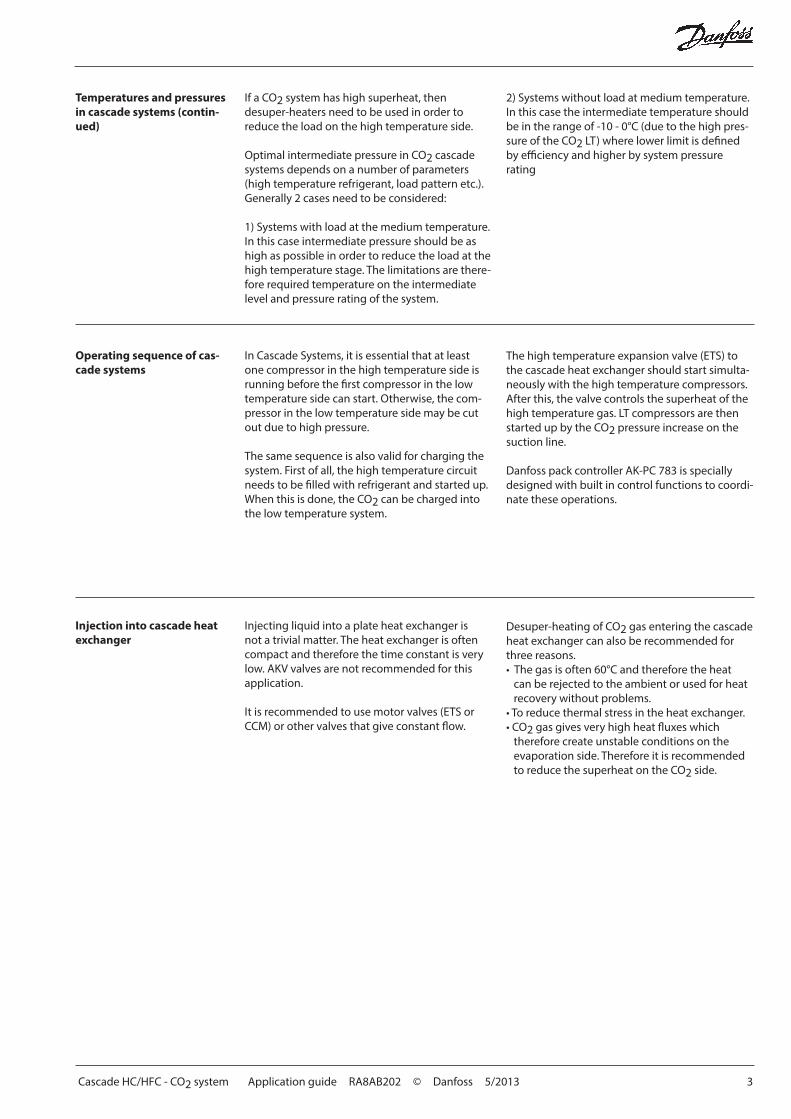
Controls of Cascade system Control of cascade systems can be divided into:• Condenser capacity control• Compressor capacity control• Cascade injection control
Condenser capacity control Capacity control of the condenser can be ac-complished via step regulation or speed control of the fans. As regulating sensor for the capacity distribu-tor the condenser pressure should be selected. The reference for the regulation can be defined in two ways. Either as a fixed reference or as a reference that varies according to the outdoor temperature. The reference for the condensing pressure is set in °C (°F).
Compressor capacity controls
The AK-PC 783 is also able to coordinate the LT and MT start to ensure a smooth operation.Here the high-pressure compressors can start either as a result of:- Load on the high-pressure circuit - Requirements from the low-pressure circuit The high-pressure circuit will still ensure that the low-pressure circuit is only permitted to start
when at least one high-pressure compressor has started. It will also ensure that security timers and compressor timers are complied with.
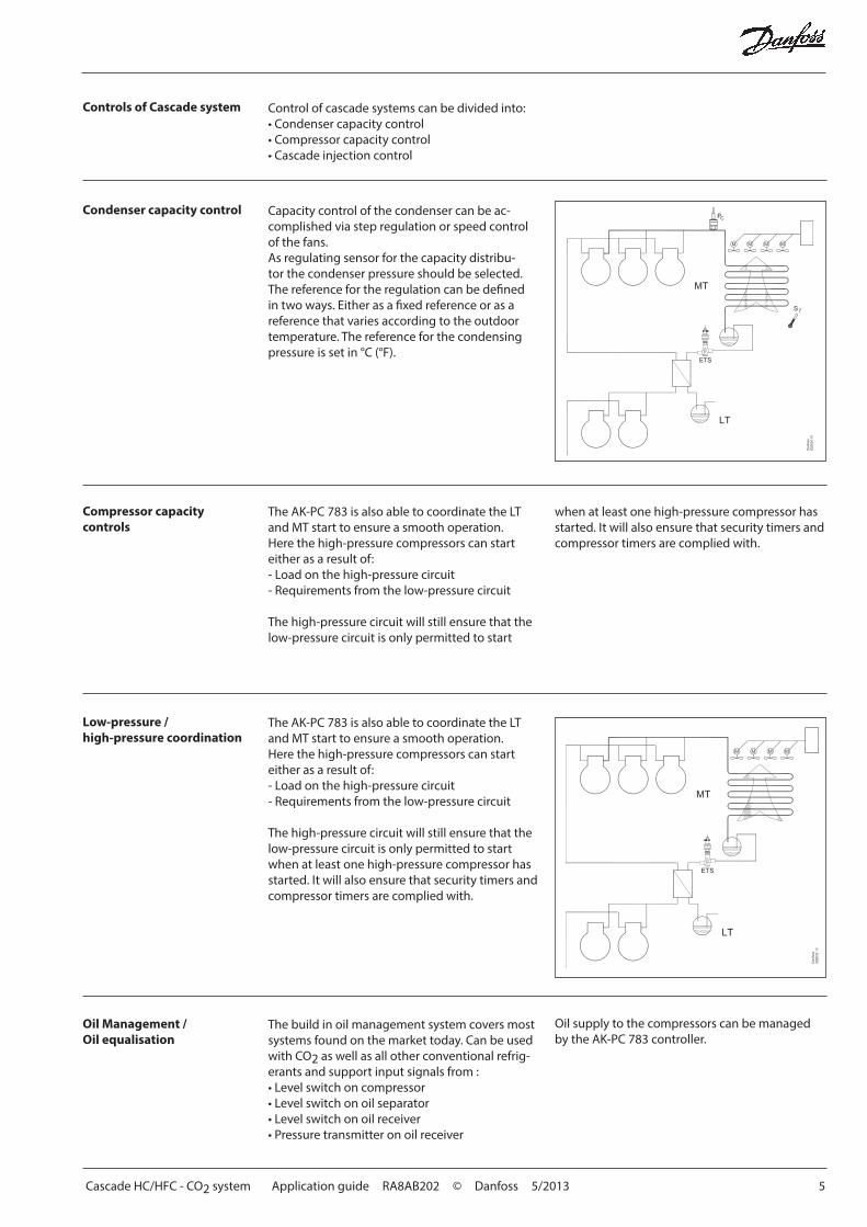
Low-pressure /high-pressure coordination
The AK-PC 783 is also able to coordinate the LT and MT start to ensure a smooth operation.Here the high-pressure compressors can start either as a result of:- Load on the high-pressure circuit - Requirements from the low-pressure circuit The high-pressure circuit will still ensure that the low-pressure circuit is only permitted to start when at least one high-pressure compressor has started. It will also ensure that security timers and compressor timers are complied with.
Oil Management / Oil equalisation
The build in oil management system covers most systems found on the market today. Can be used with CO2 as well as all other conventional refrig-erants and support input signals from :• Level switch on compressor• Level switch on oil separator• Level switch on oil receiver• Pressure transmitter on oil receiver
Oil supply to the compressors can be managed by the AK-PC 783 controller.
6 Application guide RA8AB202 © Danfoss 5/2013 Cascade HC/HFC - CO2 system
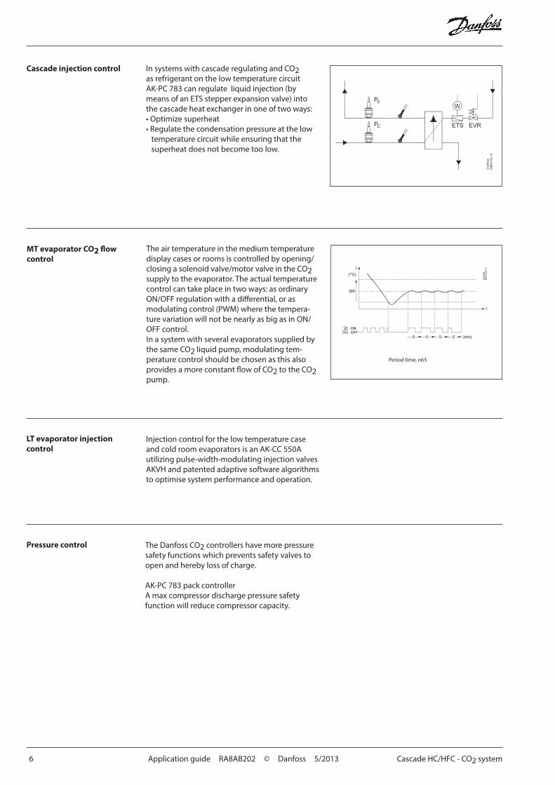
Cascade injection control In systems with cascade regulating and CO2 as refrigerant on the low temperature circuit AK-PC 783 can regulate liquid injection (by means of an ETS stepper expansion valve) into the cascade heat exchanger in one of two ways:• Optimize superheat• Regulate the condensation pressure at the low
temperature circuit while ensuring that the superheat does not become too low.
MT evaporator CO2 flow control
The air temperature in the medium temperature display cases or rooms is controlled by opening/closing a solenoid valve/motor valve in the CO2 supply to the evaporator. The actual temperature control can take place in two ways: as ordinary ON/OFF regulation with a differential, or as modulating control (PWM) where the tempera-ture variation will not be nearly as big as in ON/OFF control.In a system with several evaporators supplied by the same CO2 liquid pump, modulating tem-perature control should be chosen as this also provides a more constant flow of CO2 to the CO2 pump.
LT evaporator injection control
Injection control for the low temperature case and cold room evaporators is an AK-CC 550A utilizing pulse-width-modulating injection valves AKVH and patented adaptive software algorithms to optimise system performance and operation.
Period time, n63
Pressure control The Danfoss CO2 controllers have more pressure safety functions which prevents safety valves to open and hereby loss of charge.
AK-PC 783 pack controllerA max compressor discharge pressure safety function will reduce compressor capacity.
Cascade HC/HFC - CO2 system Application guide RA8AB202 © Danfoss 5/2013 7
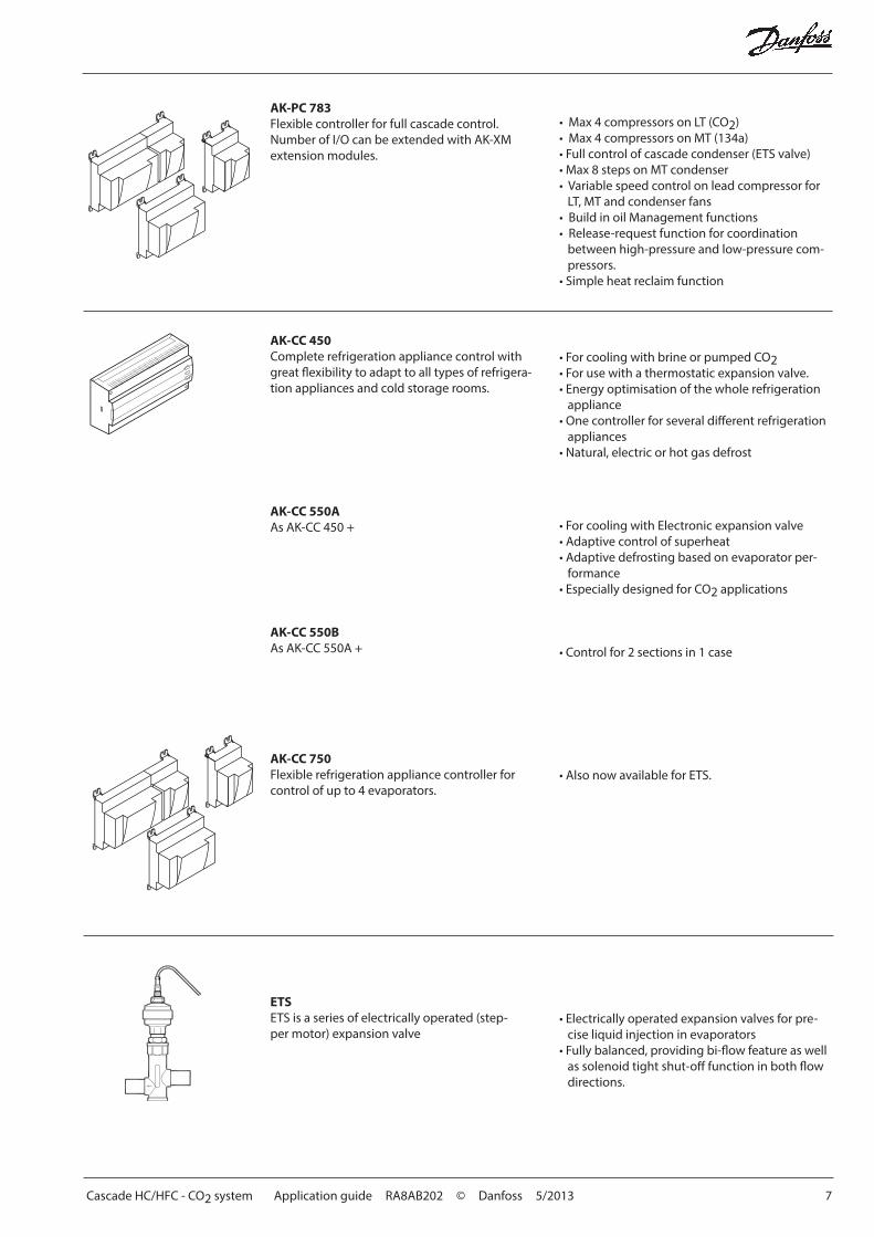
• Max 4 compressors on LT (CO2)• Max 4 compressors on MT (134a)• Full control of cascade condenser (ETS valve)• Max 8 steps on MT condenser• Variable speed control on lead compressor for
LT, MT and condenser fans• Build in oil Management functions• Release-request function for coordination
between high-pressure and low-pressure com-pressors.
• Simple heat reclaim function
AK-PC 783Flexible controller for full cascade control. Number of I/O can be extended with AK-XM extension modules.
• Electrically operated expansion valves for pre-cise liquid injection in evaporators
• Fully balanced, providing bi-flow feature as well as solenoid tight shut-off function in both flow directions.
ETSETS is a series of electrically operated (step-per motor) expansion valve
AK-CC 750Flexible refrigeration appliance controller for control of up to 4 evaporators.
AK-CC 550AAs AK-CC 450 +
AK-CC 450Complete refrigeration appliance control with great flexibility to adapt to all types of refrigera-tion appliances and cold storage rooms.
• For cooling with Electronic expansion valve • Adaptive control of superheat • Adaptive defrosting based on evaporator per-
formance• Especially designed for CO2 applications
• For cooling with brine or pumped CO2• For use with a thermostatic expansion valve.• Energy optimisation of the whole refrigeration
appliance• One controller for several different refrigeration
appliances• Natural, electric or hot gas defrost
AK-CC 550BAs AK-CC 550A + • Control for 2 sections in 1 case
• Also now available for ETS.

8 Application guide RA8AB202 © Danfoss 5/2013 Cascade HC/HFC - CO2 system
AD
AP-
KOO
L®
Danfoss can accept no responsibility for possible errors in catalogues, brochures and other printed material. Danfoss reserves the right to alter its products without notice. This also applies to products already on order provided that such alternations can be made without subsequential changes being necessary in specifications already agreed.All trademarks in this material are property of the respecitve companies. Danfoss and Danfoss logotype are trademarks of Danfoss A/S. All rights reserved.