case histories for cased crossings using an integrated...
TRANSCRIPT

“Case Histories for Cased Crossings
Using an Integrated Tool Approach with
Long Range Guided Wave”
NACE DA Conference
By Joe Pikas

Overview
• Introduction
• Corrosion and Causes– Coatings
– Shielding
– Metallic Contacts
• Criteria for Casings
• Monitoring– Electrical Tests
– Long Range Guided Wave
– Other Technologies
• Verification and Prove Up
• Maintenance
• Procedure for Testing Integrity of Carrier Pipe

Introduction
• Common Practice started w/RR X-ings
• End Seals– Concrete or Enamel w/Rope (Old Type)
– Link, Hot Applied Sleeves, etc.
– None - Concrete coated pipe w/open ends
• Spacers– Hemp Rope w/enamel (Old Type)
– Non metallic• Plastics
• Molded Epoxy Sleeves
– Concrete coated pipe

Corrosion and Causes
• Coating Deterioration– Age
– Physical Damage to Coating during construction
• Shielding– Spacers
– Insulators
– Coating
• Metallic Contact (Generally @ End(s)– Galvanic
– Drain on CP outside casing
– Stress Concentrator
• Atmospheric– High Delta t (temperature difference between pipe surface and
atmosphere)
– Humid Environment in Annulus
– Vent(s) supplying oxygen to the annulus

Criteria for a Short
“A shorted casing may exist if there is a small differential or there is no differential between the pipe to electrolyte and casing electrolyte potential.”
• Severe Indication - Pipe to Electrolyte "ON" Potentials are less than -850 mV and the difference in the Pipe and Casing Potential is less than 10 mV.
• Moderate Indication - Pipe to Electrolyte “ON” Potentials are borderline -850 mV and the difference in the P/S & C/S potentials is greater than 10 mV and less than or equal to 100 mV .
• Minor Indication - Pipe to Electrolyte “ON” Potentials are greater than -850 mV and the difference in the P/S & C/S potentials is greater than 10 mV and less than or equal to 100 mV .Electrically Clear – Pipe to Electrolyte “ON” Potentials are greater than 1000 mV and the difference P/S & C/S potentials is greater than 150 mV.

Test DescriptionSevere (Metallic
Contact)
Moderate
(Electrolytic with
Coating
Holidays)
Minor
(Electrolytic Path)Electrically Clear Remarks
Pipe to Electrolyte
Potential (Industry
Standard)
Pipe to Electrolyte
Potentials are
severely depressed
and below -850 mV
Criterion
Pipe to Electrolyte
ON Potentials are
borderline near
casing
Pipe to Electrolyte
ON Potentials are
slightly depressed
near casing
structure and are
above -850 mV
criterion
Pipe to Electrolyte
ON Potentials
show no or little
influence from
casing proximity
Pipe, Casing and
OCP Potential Tests
Should Always be
Run Together
Casing-to-Electrolyte
Potential
(Industry Standard)
Casing to
Electrolyte
Potentials track
Pipe Potentials and
the difference in
the Pipe and
Casing "ON"
Potentials < than
10 mV.
Casing to
Electrolyte ON
Potentials partially
track Pipe
Potentials and the
difference in the
P/S & C/S "ON"
potentials is
greater than or
equal to 10 mV
and less than or
equal to 100 mV .
Casing to
Electrolyte ON
Potentials partially
track Pipe
Potentials and the
difference in the
P/S & C/S "ON"
potentials is
greater than100
mV .
Difference in the
P/S & C/S "ON"
greater than 150
mV and are below
bare steel potential
for that
environment
Pipe, Casing and
OCP Potential Tests
Should Always be
Run Together
Open Circuit Potential
(OCP) between
Casing and Pipe
(Industry Standard)
Difference in Pipe
and Casing
Structure Potential
< 10 mV
Difference in the
P/S & C/S "ON"
greater than or
equal to 10 mV
and less than or
equal to 100 mV.
Difference in the
P/S & C/S "ON"
greater than100
mV.
Difference in the
P/S & C/S "ON"
greater than 150
mV.
Pipe, Casing and
OCP Potential Tests
Should Always be
Run Together
Internal Resistance
(Industry Standard)
Pipe-to-Casing
(P/C) resistance
less than or equal
to 0.01 Ω
P/C resistance
greater than 0.01
Ω and less than or
equal to 0.1 Ω.
P/C resistance
greater than 0.1 Ω.
P/C resistance
greater than 0.15 Ω
Internal Resistance
Test will determine
metal to metal
contacts
Classification Table

Test DescriptionSevere (Metallic
Contact)
Moderate
(Electrolytic with
Coating
Holidays)
Minor
(Electrolytic Path)Electrically Clear Remarks
Cycling the Rectifier
(Subjective)
Difference in the
P/S & C/S shifts
less than 10 mV
"OR" C/S shift
greater than 75%
P/S shift
Difference in the
P/S & C/S shifts
greater than or
equal to 10 mV
and less than or
equal to 100 mV
"OR" C/S shift
greater than or
equal to 25% P/S
shift and less than
or equal to 75%
P/S shift
Difference in the
P/S & C/S shifts
greater than 100
mV "AND" C/S shift
less than 25% P/S
shift
Difference in the
P/S & C/S shifts
greater than 150
mV "AND" C/S shift
less than 10% P/S
shift
Subjective
AC Signal
(Subjective)
Near total signal
loss from both
directions large
spike in mb/ft (C-
Scan) or > 80
dBmA (PCM)
Moderate Spike
mb/ft (C-Scan) or
< 80 dBmA (PCM)
Minor spike or
signal loss for
either C-Scan or
PCM
No significant
signal loss (Normal
Attenuation)
Subjective except
for direct metal to
metal contact
Polarization Test
(Panhandle Eastern
Method)
(Subjective)
P/C resistance less
than or equal to
0.01 Ω
P/C resistance
greater than 0.01
Ω and less than or
equal to 0.1 Ω.
P/C resistance
greater than 0.1 Ω.
Additional testing
required to defineSubjective
Casing-to-Pipe (C/P)
Capacitance "Shorted" display Not Defined None "Clear" display
Not Proven by
Industry
Classification Table
Note: Many of these tests were determined subjective because the results have not
been proven up empirically or by standards.

Monitoring
• Initial Electrical Field Tests– Potential Survey
• This method is the initial test conducted to identify a shorted casing. A voltmeter and a reference electrode are used to conduct these tests.
• P/S, C/S, & OCP
– Internal Resistance• This method indicates whether direct metal-to-metal contact
exists between a carrier pipe and the casing pipe by measuring electrical resistance.
• Metal to metal <0.01 ohms)
– Four Wire IR Drop• This method may indicate the existence and location of a
short.

Potential Survey

Internal Resistance

Calibration of
Four Wire Calibration

Four Wire U/S End
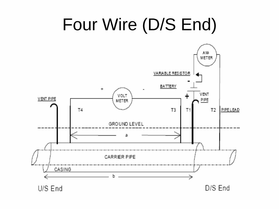
Four Wire (D/S End)

Monitoring
• Initial Electrical Field Tests (continued)
– Casing Depolarization
• Panhandle Eastern Method
– Cycling the cathodic protection rectifier is another
method used to evaluate the electrical isolation
between pipe and casing.
– AC Signal (Current Attenuation)
• This method uses a signal generator and receiver to detect
signal loss at a metallic short or a coating defect.
– Capacitive (Go-no-Go Type Test)

Monitoring
Verification Tests
• Long Range Guided Wave – This method use torsional data as well as
compressional wave modes to detect cracks, metal loss and other defects on a carrier pipe inside a casing.
• In Line Inspection or Tethered Pigs– ILI is used to determine the presence or absence of
pitting-corrosion damage on carrier pipe inside a casing.
• Hydrostatic Test (Go-no-Go Type Test)
Direct Examinations
• Excavate both End(s) of Casing – Prove Up
• Conduct Inspection for:– Condition of Carrier Pipe
• Coating
• Pipe Surface for defects
– Condition of Casing & Components• Integrity of Casing Pipe, Vent Pipes, Welds, End Seals,
Spacers, etc.
– Electrolyte/Soil/Water Testing for Corrosivity• Lab and Field
• Electrolyte inside casing annulus
• Electrolyte outside casing
Procedure for Casing Test
• Pre-Assessment
– Operations
• Temperature, Stress Levels, Dig Reports, etc.
– History
• Year installed, Leaks, Shorts, CP, MIC, etc.
– Pipe/Casing Attributes
• Diameter, W.T., SYMS, Welds, etc.
– Construction Practices
• End Seals, Spacers, Seam type, Problems, Vents, etc.
– Soils and Environmental
• Drainage, Topography, Land Use, etc.
– Corrosion Control
• Coating type, Coating Condition, Current Demand, Potentials of Pipe/Casing, Test Stations, etc.

Procedure (Continued)
• Indirect Examinations - Initial Field Tests plus (2 or more tests are recommended)
– Potential Method • Pipe to Electrolyte
• Casing to Electrolyte
• Open Circuit Potential (OCP)
Note: If OCP is < 100 mV and P/S below -850 conduct or likelihood of atmospheric may corrosion exist, conduct additional verification tests for corrosion or no corrosion.
– Resistance Test
– 0.01 ohms or less Metallic Contact
– >0.01 and less 0.10 ohms Possible Electrolytic Couple
– >0.10 ohms - Little or no electrolyte in annulus
– 4 Wire IR Drop Test – Determine End or Ends for Metallic Short

Procedure for Casing Testing
• Indirect Exams (Verification Field
Tests) Determine Likelihood of:
– Metallic Contact (Stress Riser),
– Galvanic,
– MIC,
– Atmospheric Corrosion,
– History of Leaks,
– Any Threats to Cause an Integrity Problems

Procedure for Casing Testing– Conduct borescope, temperature and humidity tests
– Conduct C-SCAN or PCM Tests• Determine if end or ends are metallically shorted
• Determine coating holidays on carrier pipe where water is present
– Conduct 18 Point Long Range Guided Wave Test
• Verify the presence or no presence of corrosion
• Determine depth and length of metal loss– B31.G calculations to determine integrity

Procedure for Casing Tests
• Direct Examinations– Reason for Inspection (Metallic Short/Atmospheric Corrosion)
• Location
• Engineering Station # and GPS
• Pipe Attributes
– Coating Type's) and Evaluation
– Environment (Soil/Water – Field/Lab)
– Evidence of
• Corrosion, SCC, Defect, Damage, etc.
– Repair
• Recoat, Composite Sleeve, Replace, etc.
– Type of Tests Performed
• MIC, UT, Mag. Particle, Dye Penetrant, pH, resistivity, Conformable Array, etc.

New Corrosion Mapping Tool
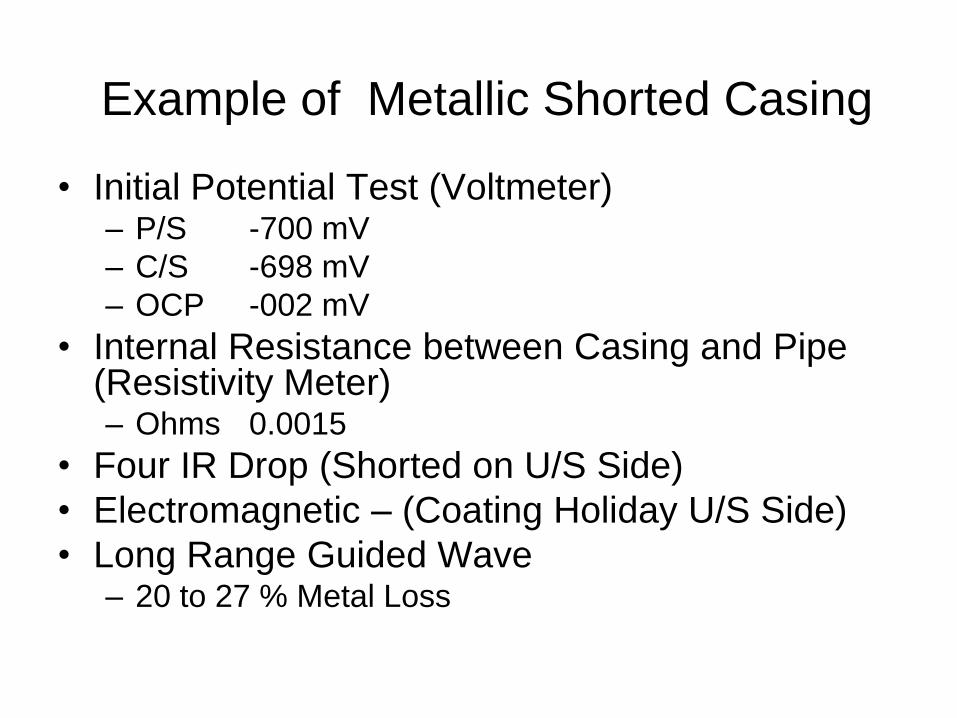
Example of Metallic Shorted Casing
• Initial Potential Test (Voltmeter)– P/S -700 mV
– C/S -698 mV
– OCP -002 mV
• Internal Resistance between Casing and Pipe (Resistivity Meter)– Ohms 0.0015
• Four IR Drop (Shorted on U/S Side)
• Electromagnetic – (Coating Holiday U/S Side)
• Long Range Guided Wave– 20 to 27 % Metal Loss
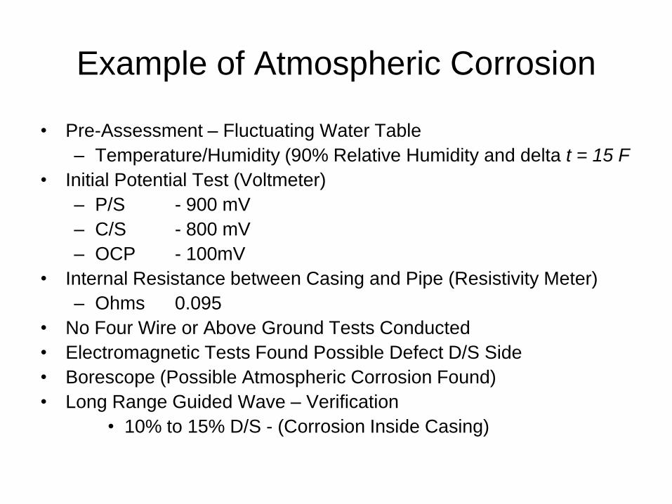
Example of Atmospheric Corrosion
• Pre-Assessment – Fluctuating Water Table
– Temperature/Humidity (90% Relative Humidity and delta t = 15 F
• Initial Potential Test (Voltmeter)
– P/S - 900 mV
– C/S - 800 mV
– OCP - 100mV
• Internal Resistance between Casing and Pipe (Resistivity Meter)
– Ohms 0.095
• No Four Wire or Above Ground Tests Conducted
• Electromagnetic Tests Found Possible Defect D/S Side
• Borescope (Possible Atmospheric Corrosion Found)
• Long Range Guided Wave – Verification
• 10% to 15% D/S - (Corrosion Inside Casing)

GUL – Shorted Casing

GUL Dual Collar, Pitch/Catch

Cased X-ing Mitigation
• Eliminate metal to metal contact– Remove casing end if feasible
• Replace carrier pipe
• Provide supplemental cathodic protection to the
carrier pipe
• Fill casing with a high dielectric material
• Apply coating or recoat the carrier pipe
• Replace end seals
• Remove, flush electrolyte and debris from inside the casing
• Monitor the condition of the carrier pipe
• Install a new pipe crossing such as using a directional drill
• Inject vapor and or water based type inhibitor in annulus

Conclusions
• Found Metallic Short - U/S side
– Potential, Resistance and 4 Wire Tests showed metallic short
– Electromagnetic test showed possible short
– GUL showed 20 to 27% Metal loss
• Found Atmospheric Corrosion on D/S Side
– Pre-assessment showed likelihood of atmospheric corrosion
– Potential and Resistance tests showed electrolyte in casing
– Electromagnetic tests showed possible coating indication
– Borescope showed indication of atmospheric corrosion
– GUL showed 10 to 20% metal loss

Conclusions
• Indirect Tools Found Problems– Potential Surveys, Resistance Tests, etc.
– Electromagnetic surveys (C-Scan/PCM)
– Borescope, Temperature, Humidity, etc.
• Tools Confirmed Indications– Long Range Guided Wave
• Direct Examination Verified Findings by Indirect Surveys– Conformable Array used in inaccessible areas
between casing and pipe.

Questions
• Corrosion and Causes
• Criteria for Casings
• Monitoring
– Borescope, Temperature, Humidity, etc.
• Maintenance/Mitigation
• Procedures for Testing Integrity of Carrier
Pipe (Electromagnetic Tools)
• Use of Long Range Guided Wave (GUL)
• Other Technologies