case studies of duct retrofits and guidelines for attic - wiki.ornl.gov
TRANSCRIPT

ORNL/TM-2011/??
ORNL/TM-0000/00
Case Studies of Duct Retrofits and Guidelines for Attic and Crawl Space Duct Sealing
November 2011
Prepared by Philip Boudreaux Jeffrey E. Christian Roderick Jackson
DOCUMENT AVAILABILITY
Reports produced after January 1, 1996, are generally available free via the U.S. Department of Energy (DOE) Information Bridge.
Web site http://www.osti.gov/bridge Reports produced before January 1, 1996, may be purchased by members of the public from the following source.
National Technical Information Service 5285 Port Royal Road Springfield, VA 22161 Telephone 703-605-6000 (1-800-553-6847) TDD 703-487-4639 Fax 703-605-6900 E-mail [email protected] Web site http://www.ntis.gov/support/ordernowabout.htm Reports are available to DOE employees, DOE contractors, Energy Technology Data Exchange (ETDE) representatives, and International Nuclear Information System (INIS) representatives from the following source.
Office of Scientific and Technical Information P.O. Box 62 Oak Ridge, TN 37831 Telephone 865-576-8401 Fax 865-576-5728 E-mail [email protected] Web site http://www.osti.gov/contact.html
This report was prepared as an account of work sponsored by an agency of the United States Government. Neither the United States Government nor any agency thereof, nor any of their employees, makes any warranty, express or implied, or assumes any legal liability or responsibility for the accuracy, completeness, or usefulness of any information, apparatus, product, or process disclosed, or represents that its use would not infringe privately owned rights. Reference herein to any specific commercial product, process, or service by trade name, trademark, manufacturer, or otherwise, does not necessarily constitute or imply its endorsement, recommendation, or favoring by the United States Government or any agency thereof. The views and opinions of authors expressed herein do not necessarily state or reflect those of the United States Government or any agency thereof.

ORNL/TM-0000/00
Energy and Transportation Sciences Division
Case Studies of Duct Retrofits and Guidelines for Attic and Crawl Space Duct Sealing
Philip Boudreaux
Jeffrey Christian
Roderick Jackson
November 2011
Prepared by
OAK RIDGE NATIONAL LABORATORY
Oak Ridge, Tennessee 37831-6283
managed by
UT-BATTELLE, LLC
for the
U.S. DEPARTMENT OF ENERGY
under contract DE-AC05-00OR22725

iii
CONTENTS
Abstract ......................................................................................................................................................... v
1. Introduction .............................................................................................................................................. 1
2. Duct Sealing Practices in the mixed-humid climate ................................................................................ 2 2.1 Historical Duct Sealing Practices .................................................................................................... 2 2.2 Current Duct sealing Practices ........................................................................................................ 4 2.3 Novel duct sealing practices ............................................................................................................ 4
3. Case Study of HVAC Duct Retrofits ....................................................................................................... 5 3.1 Candlewick ...................................................................................................................................... 5
3.1.1 Pre-Retrofit Condition .......................................................................................................... 5 3.1.2 Retrofit Measures ................................................................................................................. 7 3.1.3 Post-Retrofit Condition ........................................................................................................ 8
3.2 Baker ............................................................................................................................................... 9 3.2.1 Pre-Retrofit Condition .......................................................................................................... 9 3.2.2 Retrofit Measures ................................................................................................................. 9 3.2.3 Post-Retrofit Condition ........................................................................................................ 9
3.3 Campbell Creek ............................................................................................................................... 9 3.3.1 Pre-Retrofit Condition .......................................................................................................... 9 3.3.2 Retrofit Measures ................................................................................................................. 9 3.3.3 Post-Retrofit Condition ........................................................................................................ 9
3.4 New York ...................................................................................................................................... 10 3.4.1 Pre-Retrofit Condition ........................................................................................................ 10 3.4.2 Retrofit Measures ............................................................................................................... 10 3.4.3 Post-Retrofit Condition ...................................................................................................... 10
3.5 South Carolina ............................................................................................................................... 10 3.5.1 Pre-Retrofit Condition ........................................................................................................ 10 3.5.2 Retrofit Measures ............................................................................................................... 10 3.5.3 Post-Retrofit Condition ...................................................................................................... 10
3.6 Virginia .......................................................................................................................................... 10 3.6.1 Pre-Retrofit Condition ........................................................................................................ 10 3.6.2 Retrofit Measures ............................................................................................................... 11 3.6.3 Post-Retrofit Condition ...................................................................................................... 11
3.7 North Carolina ............................................................................................................................... 11 3.7.1 Pre-Retrofit Condition ........................................................................................................ 11 3.7.2 Retrofit Measures ............................................................................................................... 11 3.7.3 Post-Retrofit Condition ...................................................................................................... 11
3.8 Eagle .............................................................................................................................................. 11 3.8.1 Pre-Retrofit Condition ........................................................................................................ 11 3.8.2 Retrofit Measures ............................................................................................................... 12 3.8.3 Post-Retrofit Condition ...................................................................................................... 12
3.9 Yellow Jacket ................................................................................................................................ 12 3.9.1 Pre-Retrofit Condition ........................................................................................................ 12 3.9.2 Retrofit Measures ............................................................................................................... 12 3.9.3 Post-Retrofit Condition ...................................................................................................... 12
3.10 Lakeview ..................................................................................................................................... 13 3.10.1 Pre-Retrofit Condition ....................................................................................................... 13
iv
3.10.2 Retrofit Measures ............................................................................................................. 13 3.10.3 Post-Retrofit Condition .................................................................................................... 13
4. Conclusions ............................................................................................................................................ 13 4.1 Results of duct retrofit case studies ............................................................................................... 13 4.2 Lessons Learned ............................................................................................................................ 15
4.2.1 Homeowners ....................................................................................................................... 15 4.2.2 Calculating measured energy savings ................................................................................ 15 4.2.3 Variability of costs ............................................................................................................. 15 4.2.4 Challenge in targeting areas of high duct leakage .............................................................. 15
4.3 Duct Retrofit Decision Chart ......................................................................................................... 16 4.4 General Best Practices ................................................................................................................... 17
4.4.1 Threshold Leakage for Duct Sealing .................................................................................. 17 4.4.2 Make Sure Ducting is Sized Right ..................................................................................... 17 4.4.3 Preparation ......................................................................................................................... 17 4.4.4 Repair Largest Holes First .................................................................................................. 17 4.4.5 Insulate Ducts in Unconditioned Spaces ............................................................................ 17 4.4.6 Using Tape or Mastic ......................................................................................................... 17 4.4.7 Protect Yourself From Hazards .......................................................................................... 18 4.4.8 Flexible Duct ― Connection to Metal Collar Take-Off or Sleeve ..................................... 18 4.4.9 Galvanized Steel (Sheet Metal) Ductwork ......................................................................... 18 4.4.10 Fiberglass Duct Board (IBS Advisors, LLC 2007) .......................................................... 18 4.4.11 Wall Cavities or Floor Joist Cavities ................................................................................ 19
6. References .............................................................................................................................................. 22

v
ABSTRACT
The U.S. Department of Energy (DOE) is fully committed to research for developing the information and
capabilities necessary to provide cost-effective residential retrofits yielding 50% energy savings within
the next several years. Heating, ventilation, and air conditioning (HVAC) is the biggest energy end use in
the residential sector, and a significant amount of energy can be wasted through leaky ductwork in
unconditioned spaces such as attics and crawl spaces. A detailed duct sealing case study is presented for
one house along with nine brief descriptions of other duct retrofits completed in the mixed-humid climate.
Costs and estimated energy savings are reported for most of the ten houses. Costs for the retrofits ranged
from $0.92/ft2 to $1.80/ft
2 of living space and estimated yearly energy cost savings due to the duct
retrofits range from 1.8% to 18.5%. Lessons learned and duct sealing guidelines based on these ten
houses, as well as close work with the HVAC industry in the mixed-humid climate of East Tennessee,
northern Georgia, and south-central Kentucky are presented. It is hoped that the lessons learned and
guidelines will influence local HVAC contractors, energy auditors, and homeowners when diagnosing or
repairing HVAC duct leakage and will be useful for steering DOE’s future research in this area.

vi

1
1. INTRODUCTION
Heating, ventilation, and air conditioning (HVAC) is the biggest energy end use in the residential sector,
and 2040% of HVAC energy use in residential buildings is lost through leaky ducts (U.S. EPA 2009;
LBNL 2001; Vineyard, Linkous, and Baskin 2003). This energy loss is due to two main factors: leaky
ducts, and uninsulated or poorly insulated ducts.
Leaky ducts lose energy through convection when conditioned air leaks into unconditioned spaces such as
attics and crawl spaces or to the outside, and also when unconditioned air is sucked into the return ducts.
These are the biggest avenues of energy loss in HVAC systems.
Uninsulated or poorly insulated ducts lose energy through conduction when the air in the ducts heats or
cools the ductwork and then the ductwork heats or cools the air around the duct. This type of energy
transfer is reduced by installing insulation on the ducts, which resists energy loss by conduction.
The energy loss is worse when ducts are installed outside the building’s conditioned space, which is
common in residential construction, particularly in the mixed-humid climate. When ducts are installed in
a vented attic or crawl space, more energy is lost through conduction than if ducts were inside the
conditioned space because of the larger temperature difference between the ducts and the surrounding air.
If ducts are leaky, energy is also lost though convection, with only a percentage of the air flowing through
the ducts arriving at the desired location. If ducts are inside the conditioned space then leakage imposes a
smaller energy penalty because the conditioned air is at least leaking into spaces intended to be heated or
cooled.
Energy losses through conduction and convection can be addressed by sealing and insulating the HVAC
ducts. These retrofits will save money and energy and increase indoor air quality and occupant comfort.
This report focuses on sealing and insulating ducts in unconditioned spaces, with best practices geared
toward the mixed-humid climate. The authors discuss historical, current, and novel duct sealing practices,
all of which help inform duct retrofit efforts. A case study is presented on duct improvements in a home
built in 1985, along with brief descriptions of nine other duct retrofit cases in the area. One of these cases
actually uses two research houses which were built in 2009, in which occupancy is simulated and
extensive instrumentation is installed to monitor and measure energy performance. In both houses the
ductwork is at least up to current minimum code, and in one of them the ductwork was installed in the
insulated and conditioned attic. The other nine homes were built between 1909 and 1996, are occupied,
and are undergoing deep energy retrofits which include mitigating duct leaks which result in air leakage
to the outside. Reductions in duct leakage and cost and energy savings estimates are presented for most of
these ten houses. Finally, lessons learned and general guidelines are presented along with a decision tree
to help homeowners or contractors determine the scope of a duct retrofit.
The guidelines for duct sealing in the mixed-humid climate of East Tennessee are informed by ORNL’s
close work with the HVAC industry and energy auditors in the area, as well as a literature review. The
guidelines are also based on results from Oak Ridge National Laboratory’s (ORNL’s) work in ten
research houses in East Tennessee. It is hoped that this report will help homeowners and contractors
determine the most cost-effective scope of potential duct retrofits. DOE can also use this report to guide
future research into integrating duct retrofits into whole-house “deep” retrofit packages that yield energy
savings of 4050%
2
2. DUCT SEALING PRACTICES IN THE MIXED-HUMID CLIMATE
2.1 HISTORICAL DUCT SEALING PRACTICES
Many different practices have been used over the years by the HVAC industry in installing, insulating,
and sealing ducts. In the 1970s, the energy crisis caused the nation to think about how to save energy in
homes. Buildings were air-sealed to reduce infiltration and exfiltration, insulation was increased in
homes, and space conditioning equipment was turned off in some buildings (Air Quality Sciences, Inc.
2006). An unintended side effect of these new ideas was that indoor air quality worsened in some homes
because of insufficient fresh air ventilation. Although some of the ideas for building more energy efficient
homes from the 1970s carried over into the coming decades, as energy prices went back down, conserving
energy generally became less important. However, energy researchers and conservation proponents of the
1970s continued to believe in the importance of energy efficiency. Now, in the twenty-first century, as
energy prices are rising, energy efficiency is extremely important in the minds of the public, and we need
to focus on both energy efficiency and air quality. When examining duct systems in the current residential
building stock, we understand why air-sealing of ductwork was not done: energy was cheap. The duct
sealing and insulating guidance offered in this report is relevant to the current residential building stock
spanning houses built in 2011 to homes more than 100 years old.
Ductwork in a house can be made of galvanized steel, fiberglass or fiberglass duct board, aluminum pre-
insulated panels, flexible (flex) ducts, or even wall cavities or floor joist cavities (Yingling, Luebes, and
Johnson 1981). Connections, transitions, and seams in ductwork are not always sealed. Common methods
used when they are sealed are duct tape (fabric mesh with rubber adhesive) or various types of aluminum
(foil) furnace tape. Sometimes butyl rubber/mastic tape is seen, and rarely liquid mastic is used.
If duct tape was used it will have degraded over time and the duct will no longer be well sealed
(Lawrence Berkeley Laboratory 1999). Where a wall or floor joist cavity was used as a chase, it most
likely was not air-sealed, or if it was, it is no longer air-tight because of the dramatic differences in
expansion and contraction of dissimilar materials such as wood and galvanized metal. If foil tape, even
UL 181, was used, the acrylic adhesive has possibly broken down and peeled away from the duct (IBS
Advisors, LLC 2007). Over time ducts can become disconnected from diffusers, and connections to
trunks may become unsound, if the ducts were not mechanically fastened with sheet metal screws or tie
wraps at commissioning.
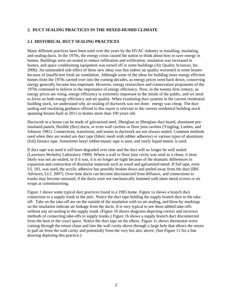
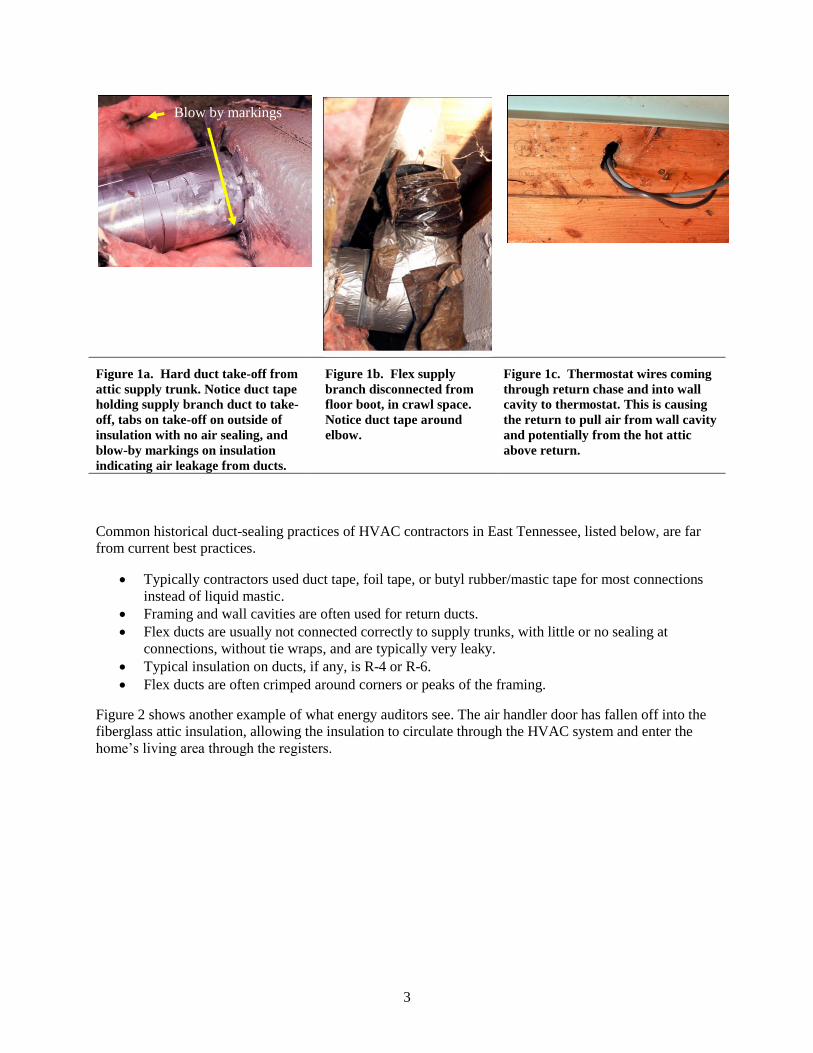
Figure 1 shows some typical duct practices found in a 1985 home. Figure 1a shows a branch duct
connection to a supply trunk in the attic. Notice the duct tape holding the supply branch duct to the take-
off: Tabs on the take-off are on the outside of the insulation with no air-sealing, and blow-by markings
on the insulation indicate air leakage from the ducts. It is very typical to see these tabbed take-offs
without any air-sealing to the supply trunk. (Figure 10 shows diagrams depicting correct and incorrect
methods of connecting take-offs to supply trunks.) Figure 1b shows a supply branch duct disconnected
from the boot in the crawl space. Notice the duct tape on the elbow. Figure 1c shows thermostat wires
coming through the return chase and into the wall cavity above through a large hole that allows the return
to pull air from the wall cavity and potentially from the very hot attic above. (See Figure 11 for a line
drawing depicting this practice.)
3
Figure 1a. Hard duct take-off from
attic supply trunk. Notice duct tape
holding supply branch duct to take-
off, tabs on take-off on outside of
insulation with no air sealing, and
blow-by markings on insulation
indicating air leakage from ducts.
Figure 1b. Flex supply
branch disconnected from
floor boot, in crawl space.
Notice duct tape around
elbow.
Figure 1c. Thermostat wires coming
through return chase and into wall
cavity to thermostat. This is causing
the return to pull air from wall cavity
and potentially from the hot attic
above return.
Common historical duct-sealing practices of HVAC contractors in East Tennessee, listed below, are far
from current best practices.
Typically contractors used duct tape, foil tape, or butyl rubber/mastic tape for most connections
instead of liquid mastic.
Framing and wall cavities are often used for return ducts.
Flex ducts are usually not connected correctly to supply trunks, with little or no sealing at
connections, without tie wraps, and are typically very leaky.
Typical insulation on ducts, if any, is R-4 or R-6.
Flex ducts are often crimped around corners or peaks of the framing.
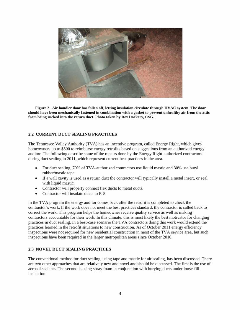
Figure 2 shows another example of what energy auditors see. The air handler door has fallen off into the
fiberglass attic insulation, allowing the insulation to circulate through the HVAC system and enter the
home’s living area through the registers.
Blow by markings
4
Figure 2. Air handler door has fallen off, letting insulation circulate through HVAC system. The door
should have been mechanically fastened in combination with a gasket to prevent unhealthy air from the attic
from being sucked into the return duct. Photo taken by Rex Dockery, CSG.
2.2 CURRENT DUCT SEALING PRACTICES
The Tennessee Valley Authority (TVA) has an incentive program, called Energy Right, which gives
homeowners up to $500 to reimburse energy retrofits based on suggestions from an authorized energy
auditor. The following describe some of the repairs done by the Energy Right-authorized contractors
during duct sealing in 2011, which represent current best practices in the area.
For duct sealing, 70% of TVA-authorized contractors use liquid mastic and 30% use butyl
rubber/mastic tape.
If a wall cavity is used as a return duct the contractor will typically install a metal insert, or seal
with liquid mastic.
Contractor will properly connect flex ducts to metal ducts.
Contractor will insulate ducts to R-8.
In the TVA program the energy auditor comes back after the retrofit is completed to check the
contractor’s work. If the work does not meet the best practices standard, the contractor is called back to
correct the work. This program helps the homeowner receive quality service as well as making
contractors accountable for their work. In this climate, this is most likely the best motivator for changing
practices in duct sealing. In a best-case scenario the TVA contractors doing this work would extend the
practices learned in the retrofit situations to new construction. As of October 2011 energy efficiency
inspections were not required for new residential construction in most of the TVA service area, but such
inspections have been required in the larger metropolitan areas since October 2010.
2.3 NOVEL DUCT SEALING PRACTICES
The conventional method for duct sealing, using tape and mastic for air sealing, has been discussed. There
are two other approaches that are relatively new and novel and should be discussed. The first is the use of
aerosol sealants. The second is using spray foam in conjunction with burying ducts under loose-fill
insulation.
5
The aerosol method (commercially known as Aeroseal®) was developed by Lawrence Berkeley National
Laboratory (LBNL) in 1987. LBNL Researchers saw the need for a more convenient method of duct
sealing, since the traditional method is time- and labor-intensive and some duct systems are not
accessible. The aerosol sealing process involves closing the supply and return registers of the duct system
and attaching the aerosol device to one of the registers. The aerosol duct sealing machine blows
aerosolized adhesive particles into the duct system along with air. As air turns corners these heavier
adhesive particles collide with the edges of holes in the ducts. The adhesive particles can seal holes as
large as 1 inch but this method is most practical for holes less than 3/8 inch across. As the sealant is
blown into the system the duct leakage is monitored in real time. The procedure can be done for a single-
family home in 30 minutes to 1 hour. Aeroseal® technology is responsible for 3,000 – 4,000 duct seals
per year, and more than 25,000 duct seals have been completed since its commercialization (LBNL 2011).
Currently there are nine dealers in the mixed-humid climate of the United States (Aeroseal, LLC 2011).
The second novel duct sealing method is to spray closed-cell foam around entire ducts and bury them
under loose-fill insulation. Steven Winter Associates (SWA), Inc. has investigated this practice in vented
attics (CARB 2009). This is similar to simply burying attic ducts in loose-fill insulation, but the problem
with this practice, especially in the mixed-humid climate of East Tennessee, is that it can cause
condensation to form on the ducts and drip onto the attic floor below. After computer modeling, SWA
found that R-4.2 flex duct buried with 3.5 inches of loose-fill insulation on top of the duct brings the
ductwork to an equivalent R-28, and burying with insulation just covering the top of the ducts gives an
effective R-14. Experiments done in California homes showed that buried R-15 duct systems reduced
peak loads enough to downsize HVAC equipment by a half-ton. Next SWA went to the humid climate of
Florida to experiment with the buried duct scenario. As expected, condensation formed on the ducts
during brief periods of the year. To remedy this SWA first sprayed 1 inch of closed-cell foam over the
attic flex duct (to reach R-13 when combined with the R-6 of the flex duct) and then buried the ducts in
blown cellulose insulation. The closed-cell foam does three things. First it air-seals the ducts, then it
contains duct condensation, and finally it insulates the ducts. This study was successful and no
condensation penetrated the closed-cell foam barrier into the attic. Before using this approach local
building codes should be checked to make sure that they allow using closed-cell foam in this way.
3. CASE STUDY OF HVAC DUCT RETROFITS
An extensive case study of a duct retrofit for one home is presented below, followed by an overview of
duct sealing retrofits at nine other homes. Aliases are used to identify each home, and do not describe the
location of the homes. Seven of the homes are described in more detail in a technical report (Jackson
2011). In many of these houses the attic was encapsulated, meaning that the attic was brought into the
building envelope by sealing the space from the outside by closing the gable, ridge, soffit and any other
vents. This is accomplished by spraying open-cell foam from the ridge line all the way to the soffits. Any
other penetration to the attic ceiling is also sealed. The spray foam air-seals as well as insulates the attic
space. Also note that all following duct leakage values are measured as duct leakage to the outside and are
not a total duct leakage measurement.
3.1 CANDLEWICK
3.1.1 Pre-Retrofit Condition
The Candlewick house underwent significant duct retrofits. After visual inspection of the ducts by the
home owner and then by a TVA Energy Right auditor, the recommendation was to replace ducts in the
vented crawl space and seal the ducts in the vented attic. The crawl space ducts had clearly not been
installed correctly and consequently the connections between duct sections were leaking. The ducts also

6
had holes in them that were made by the local wildlife (Figure 3). Measures to correct these problems
were at the top of the TVA auditor’s list because their payback would potentially be the greatest of all the
recommended energy retrofits.
Figure 3. State of ducts in the Candlewick house crawl space before retrofit.
This house was built in 1985, is 1650 ft
2, and at the time of retrofit was 26 years old. Before the retrofit a
duct leakage test was conducted by pressurizing the house to 25 Pascal (Pa), then pressurizing the ducts to
25 Pa. This setup stops air movement between the house and duct system, so that any measured duct
leakage is from the ducts to the outside of the conditioned space. The test result was a duct leakage rate of
245 cubic feet per minute (cfm) at 25 Pa (cfm25).
Duct leakage results in cfm can be normalized to a home by either dividing by the floor area of the home,
or dividing by the air handler flow. The duct leakage as compared to the floor area of the home in this
case is 14.8%. The Building America Builder’s Challenge states that the goal for duct leakage to the
outside should be no greater than 5% (BA 2008). The air handler flow of this house was measured by a
vane anemometer to be 940 cfm, which yielded a duct leakage to the outside of 26.1% (as compared to air
handler flow). This is well above the 10% that the Building Performance Institute (BPI) recommends as
the maximum allowable duct leakage (BPI 2007).
The homeowner received three quotes for duct retrofit work and settled on “Company 2” because they
proposed to use liquid mastic and R-8 insulation on the ducts that would be replaced in the crawl space
and to seal the ducts in the attic. Table 1 gives information on each quote.
Table 1. Details of three quotes for Candlewick house duct retrofits
Cost Work to be done Insulation on
replaced ducts
Sealing
technique
Company 1 $4100 Replace crawl space ducts R-6 Liquid mastic

7
Company 2 $3500 Replace crawl space ducts/
Seal attic ducts
R-8 Liquid mastic
Company 3 $2700 Replace crawl space ducts R-6 Butyl rubber
/mastic tape
3.1.2 Retrofit Measures
For this duct retrofit all the ducts in the crawl space were removed and replaced with a round hard duct
supply trunk with flex duct supply branches to the floor registers. A scoop was installed where the metal
chase comes off the supply trunk to the attic to increase air flow to the upstairs registers. A scoop is a
smooth, low-restriction method of redirecting duct air flow by 90 degrees (see Figure 4).
Figure 4. A round take-off collar with a scoop. The scoop helps to turn more of the air in the main trunk
up though the take-off.
The return duct was replaced with a flex return. In Figure 5, images showing good duct sealing practices
for the supply trunk are presented. Figure 5a shows the round sheet metal supply trunk being sealed.
Longitudinal seams, called Pittsburgh seams, run horizontally on the hard duct sections and are important
because they hold the duct pieces together. These seams should not leak under pressure. The duct sections
come flat and can be put together at the job site; the sheets are rolled into a tube and snapped together.
The Pittsburgh seam is reinforced with sheet metal screws, then the seam and screw heads are taped over,
and finally mastic is applied over the tape and to a tape width on either side. Figure 5b shows a reducing
flange in the supply trunk. Joints and seams are screwed together, and then fiberglass mesh tape is
applied. Next mastic is applied over the mesh tape and to one tape width on each side. Figure 5c shows
the take-offs on the supply trunk. They are screwed to the supply trunk (where a foam gasket is
sandwiched between the take-off and trunk), mastic is then used to seal the take-offs to the trunk (an
added measure because the gasket will degrade over time), and then insulation is added and the insulation
facing is taped.

8
Figure 5a. Round hard duct supply
trunk. Pittsburgh seam is reinforced
with sheet metal screws, then seam
and screw heads are taped over with
a rubber adhesive cloth tape, and
finally mastic is applied over the
tape and to one tape width on either
side of tape.
Figure 5b. Reducing flange in
supply trunk. Joints and seams are
screwed together, then fiberglass
mesh tape is applied. Next mastic is
applied over the mesh tape and to
one tape width on each side.
Figure 5c. Take-offs are
screwed to supply trunk, then
mastic is used to seal take-offs
to trunk.
Figure 6 shows details of air-sealing the existing boots in the floor. Figure 6a shows water-based mastic
applied to the inside of a hard duct connection from the boot in the floor above. This practice seals any
seams in the connection between the boot and hard duct, which is sometimes easier to do from inside the
house than from outside. Figure 6b shows mastic on the inside of the boot below the floor supply register
(picture is taken from inside the house). It is better to use water-based mastic than solvent-based mastic
inside the home because of the high content of volatile organic compounds in solvent-based mastic.
Always read the material safety data sheet to ensure that hazards are controlled and the product is used
safely.
3.1.3 Post-Retrofit Condition
Since the duct retrofit was done, the homeowners have noticed an improvement in air quality and
comfort, and hope to see energy savings in the coming months. Before the ducts were sealed the relative
humidity in the home was typically 55% during the summer; after the retrofit it was 45%; and the
homeowners are now comfortable setting the thermostat 2 degrees higher in the summer because of the
lower humidity. Musty smells on the first floor of the home are gone. The duct leakage was measured
after the retrofit to be 72 cfm25. The duct leakage to the outside after the duct retrofit was 7.4% compared
to system air flow (971 cfm post-retrofit) and 4.4% compared to floor area.
Figure 6a. Mastic applied to inside of hard duct connection
(from boot to flex connection in crawl space). This practice seals
any seams in the connection between the boot and hard duct.
Figure 6b. Mastic on inside of boot
(looking from inside the home).

9
3.2 BAKER
3.2.1 Pre-Retrofit Condition
The HVAC unit in the Baker house is in the unfinished conditioned basement. Inspection of the ducts
revealed wall cavities used as ducts, which are very difficult to seal in a retrofit situation. Since the Baker
house also had a significant amount of outside air infiltration coming in from the front porch cantilever,
using wall cavities as ductwork imposed an even greater energy penalty. Upon initial testing the duct
leakage in this home was too great to measure, as the duct system was too leaky to pressurize to 25 Pa.
3.2.2 Retrofit Measures
The homeowner had the basement HVAC unit replaced and the accessible ductwork was replaced or
sealed.
3.2.3 Post-Retrofit Condition
Post-retrofit measurements showed that the duct leakage rate to the outside is 144 cfm25. With 4122 ft2 of
floor area this amounts to 3.5% duct leakage, or 15% of air handler flow (960 cfm). A post-retrofit
inspection revealed that leakage is still coming from the ducts located in the cavity space between the two
floors.
3.3 CAMPBELL CREEK
3.3.1 Pre-Retrofit Condition
Two houses make up the pre- and post-retrofit conditions of the Campbell Creek house. The base house
(pre-retrofit condition) is a 2351 ft2 home with a vented attic and two HVAC units, one in the garage and
one in the attic. The duct leakage of these two systems was measured to be 131 cfm25 for the upstairs unit
and 52 cfm25 for the downstairs unit. The second floor is 1016 ft2 and the first floor is 1335 ft
2, yielding
leakage rates of 10% and 5% for the second and first floors respectively. The system air flows of these
two units are 815 cfm and 593 cfm for the upstairs and downstairs. This yields a leakage rate to the
outside of 16.1% and 8.8% with respect to system air flow for the upstairs and downstairs respectively.
3.3.2 Retrofit Measures
The retrofit house (post-retrofit condition) is of the same floor plan and orientation as the base house. The
HVAC system in the retrofit house consists of only one unit in the attic. The attic is encapsulated,
meaning the soffit, gable, and ridge vents are sealed and the roof deck is coated with spray foam. This
essentially brings the attic and therefore the ducts and HVAC unit into the building envelope. Since these
homes were both new construction there was no extra cost from downsizing from two units totaling 4 tons
to one 3-ton unit in the retrofit house attic. The ductwork was sealed the same way in both houses, so any
energy savings result from the unit and ductwork being brought into the conditioned space by
encapsulating the attic.
3.3.3 Post-Retrofit Condition
Energy savings can be attributed to two mechanisms. Because the ducts are in the conditioned space duct
leakage to the outside is reduced to 60 cfm25, or compared to the whole house living area of 2351 ft2, to
2.5%. The system air flow in the retrofit house is 989 cfm, so the duct leakage to the outside is 6%
compared to the system air flow. There will also be energy savings due to the attic encapsulation because
the ducts are now in an environment with more moderate temperatures than typically observed in vented
attics with no insulation on the roof deck.
10
3.4 NEW YORK
3.4.1 Pre-Retrofit Condition
This home, located in Atlanta, had two HVAC units, one in the vented attic, and one in the vented crawl
space. Both the attic and crawl space also contained ducting insulated to R-6. The attic unit served the 820
ft2 second floor and the crawl space unit serviced the 2230 ft
2 first floor. Duct leakage to the outside of
785 cfm25 and 291 cfm25 was measured for the first- and second-floor systems respectively. The duct
leakage by floor area was 35% for both floors.
3.4.2 Retrofit Measures
The crawl space and attic were encapsulated, effectively bringing both HVAC units and ducts into the
building envelope. Both first- and second-floor duct systems were sealed or replaced if needed.
3.4.3 Post-Retrofit Condition
Duct leakage measurements yielded 267 cfm25 (12%) for the first floor and 0 cfm25 (0%) for the second
floor. The remaining duct leakage in the first floor system is likely due to registers and duct boots that are
located in interior walls, which are difficult to seal adequately.
3.5 SOUTH CAROLINA
3.5.1 Pre-Retrofit Condition
The HVAC unit and ducts are all located in the crawl space, outside the building envelope, in the South
Carolina house in Atlanta. The ducts were poorly sealed, as determined by initial diagnostic tests. Since
the ducts could not be pressurized to 25 Pa during testing, a “can’t reach factor” was used to determine a
total leakage to the outside of 1,254 cfm25 (or 42% of the conditioned floor area of 2989 ft2). Also, most
of the duct runs were either not insulated or poorly insulated with newspaper and plastic mats.
3.5.2 Retrofit Measures
A new HVAC system was relocated to the encapsulated attic, thereby bringing the system into the
conditioned space. Ceiling registers were added to replace the floor registers that had been used by the
previous system.
3.5.3 Post-Retrofit Condition
Replacing the ducts had a big impact on duct leakage. Whereas initially the duct leakage to the outside of
the building envelope was measured as 1,254 cfm25, after new ducts were installed with attention paid to
properly sealing all potential leakage points, only 68 cfm25 of duct leakage was measured. This amounts
to a 2% duct leakage rate to the outside. Additionally, because the large leakage rate contributed to
unbalanced air flows through the house, sealing the ducts will also provide superior thermal comfort.
3.6 VIRGINIA
3.6.1 Pre-Retrofit Condition
The HVAC system and ducts in this house are located in the crawl space, outside the building envelope.
There were several duct connections that were disconnected so that pressurizing the ducts to evaluate the
overall leakage was not possible.
11
3.6.2 Retrofit Measures
The ducts on the first floor were repaired and replaced where needed. Ducts in the interior walls, which
went to the second floor, could not be sealed using traditional duct sealing methods. More advanced
approaches such as Aeroseal® duct sealing could have been employed in this house. However, the
homeowners chose to install a high-efficiency, ductless, mini-split system, which provides more localized
control of the thermal environment and eliminates the ducts that were in the interior walls.
3.6.3 Post-Retrofit Condition
Whereas initially the substantial duct leakage to the outside was such that the ducts could not be
pressurized to permit measurement, after the retrofit, there is only 98 cfm25 of leakage. With a conditioned
floor area of 1670 ft2, the duct leakage after retrofit is 5.9%. The large improvement was due to all of the
ducts that provide conditioned air to the first floor being replaced with new ducts that were installed with
special attention given to minimizing leakage, and the installation of the ductless system to serve the
second floor.
3.7 NORTH CAROLINA
3.7.1 Pre-Retrofit Condition
The ducts for the first-floor HVAC system were located in the vented crawl space. While the ducts were
insulated with R-6 insulation, they were not very effective for delivering conditioned air. There were
several disconnected duct connections that made pressurizing the ducts to evaluate the overall leakage
impossible.
The ducts for second-floor HVAC system were located in the attic, with R-6 insulation on the flex ducts.
While much better than the first floor with regard to duct leakage, a duct blaster test revealed
approximately 280 cfm25 of leakage. This is equal to about 22% of the floor area (1296 ft2) served by this
system.
3.7.2 Retrofit Measures
The ducts in the attic were sealed, and the ducts in the crawl space were replaced and sealed.
3.7.3 Post-Retrofit Condition
Whereas initially the substantial duct leakage to the outside of the building envelope was such that the
ducts could not be pressurized to permit measurement, after the retrofit duct leakage for the 2407 ft2 first
floor was only 103 cfm25 (4.3%) and for the 1296 ft2 second floor was 43 cfm25 (3.3%). The large
improvement was due to replacing all of the ducts that provide conditioned air to the first floor with new
ducts that were installed with specific attention given to minimizing leakage.
3.8 EAGLE
3.8.1 Pre-Retrofit Condition
The entire HVAC system, including ducts, was located in the attic. About 60% of the ducts were insulated
with R-6 insulation, while the remaining ducts were insulated with R-8 insulation. The total conditioned
area is 1318 ft2. Testing showed duct leakage of 266 cfm25 or 20.2% of the conditioned floor area.
12
3.8.2 Retrofit Measures
In order to eliminate ducts in the attic, the HVAC system was installed in the crawl space, which has a
more moderate temperature than the attic. Since the homeowner is considering encapsulating the crawl
space, the system could be included within the building envelope in the future. Because the ductwork was
relocated to the crawl space, new floor registers were added. The original ceiling registers were capped
and flash-foamed.
3.8.3 Post-Retrofit Condition
The impact of relocating and replacing the ducts yielded a post-retrofit duct leakage rate of 160
cfm25. This brings the post-retrofit duct leakage to 9.1%. The post-retrofit floor area of the house
was increased to 1755 ft2 because a conditioned storage room and closet were added to the
conditioned space.
3.9 YELLOW JACKET
3.9.1 Pre-Retrofit Condition
For the first-floor system of this home, the ducts were minimally insulated from R-5 to R-6 and were
located in the unconditioned, unfinished basement along with the furnace. The duct leakage to the outside
for this system was about 677 cfm25, or 47.6% of the square footage (1423 ft2) served by the duct system.
The second HVAC unit and ducts were located in the attic. The ducts were insulated to approximately R-
5 to R-6. The duct leakage to the outside for the second floor system was about 105 cfm25, or 6.0% of the
square footage (1745 ft2) served by the duct system.
3.9.2 Retrofit Measures
The attic was encapsulated so it is now semi-conditioned. Per the request of the homeowner, a return was
added to each of the four bedrooms. New R-8 insulated flex duct runs were installed along with a new
HVAC system in the attic. Since the roofline has been insulated and sealed, the ducts for this particular
system are now considered to be inside the building envelope, such that air loss through duct leakage will
be contained in the living space.
The first-floor unit was not upgraded, per the homeowners’ request. They did, however, try to seal the
existing ductwork and upgraded the basement to bring this space and ducts into the conditioned building
envelope. They are intending to finished the basement as living space in the future. Enclosing the
basement space in the building envelope increased the area conditioned by the first-floor unit to 283 ft2.
3.9.3 Post-Retrofit Condition
The duct systems showed some improvement after retrofit work was completed, particularly the second
floor system, which was entirely replaced. However, the air leakage in the ducts that serve the first floor
increased after the retrofit, even though the homeowner paid to have the ducts sealed. This could be due
to additional leakage introduced when supply registers were added to the basement. The leakage is now
708 cfm25 (25%) for the first-floor system and 0 cfm25 (0%) for the second-floor system.

13
3.10 LAKEVIEW
3.10.1 Pre-Retrofit Condition
The HVAC system, along with all ducts, was located in the attic. The ducts were insulated to R-6
and duct leakage to the outside measured 526 cfm25 or 30.8% of conditioned floor area (1710
ft2).
3.10.2 Retrofit Measures
Because the system was being downsized significantly, the majority of HVAC contractors
consulted advised the homeowner to resize the ducts to match, and the homeowner decided to
follow that recommendation. The attic was also encapsulated.
3.10.3 Post-Retrofit Condition
The impact of encapsulating the attic and downsizing and replacing the ducts was significant.
The post-retrofit duct leakage to the outside was 110 cfm25, or 6.4% leakage by floor area.
4. CONCLUSIONS
4.1 RESULTS OF DUCT RETROFIT CASE STUDIES
Ten research homes were retrofitted with some measure of duct improvement, either using standard
methods of tape and mastic, replacing the duct system, bringing the ductwork inside the conditioned
space, or by a combination of these methods. Table 2 is a summary of the ten homes’ duct retrofit work,
measured pre- and post-retrofit duct leakage to the outside, retrofit costs if available (does not include
cost of HVAC unit if it was replaced), and energy savings estimated using EnergyGuage. (Energy savings
may also be estimated using a procedure presented in the Minneapolis Duct Blaster Manual (Energy
Conservatory 2011) if an EnergyGauge model of the home is not available.)

14
Table 2. Summary of duct retrofit results for ten homesa
Pre-retrofit
duct leakage Post-retrofit duct leakage
Energy
savingsb
Year built
Pre- (post-) retrofit
conditioned floor area
(ft2)
cfm cfm/ft
2
floor area
cfm cfm/ft
2
floor area
Duct retrofit measures Retrofit costs
Site Source Pre-retrofit
yearly utility bills
Estimated yearly
savings
Estimated simple
payback (years)
Candlewick 1985 1650 245 14.8% 72 4.4% Replaced and sealed ducts
in crawl, sealed ducts in attic $3000 N/A N/A $1800 $155 19
Baker 1966 4122 N/A N/A 144 3.5% Replaced and sealed basement ductwork
N/A 12% 8.5% $2500 N/A
Campbell Creek
2009 2351 183 7.8% 60 2.5% Downsized HVAC
equipment, encapsulated attic
$0 N/A N/A $1970 $365 0
New York 1920s 3050 1076 35.3% 267 8.8% Both duct systems sealed, attic and crawl space were
encapsulated $2880 7.6% 6.0% $3614 $215 13
South Carolina
1920s 2989 1254 42.0% 68 2.3% Sealed and moved to the
conditioned space (encapsulated attic)
N/A 22.7% 18.5% N/A $806 N/A
Virginia 1920s 1670 N/A N/A 98 5.9% Sealed ductwork servicing
first floor, used mini-splits for upstairs
$4480 14% 10% $2260 $234 19
North Carolina
1920s 3703 N/A N/A 146 3.9% Replaced and sealed ducts
in crawl, sealed ducts in attic $4000 9% 7% $6380 $319 13
Eagle 1955 1318
(1755) 266 20.2% 160 9.1%
Moved unit to encapsulated crawl space, new ductwork
N/A 8% 14% $2450 $255 N/A
Yellow Jacket
1970s 3168
(4576) 782 24.7% 708 15.5%
Sealed ductwork and encapsulated attic
N/A 3% 2% $2800 $52 N/A
Lakeview 1985 1710 526 30.8% 110 6.4% Replaced ductwork and
encapsulated attic $3000 4% 4% $2074 $64 47
a ”N/A” indicates that data is not available.
b Energy savings estimated by EnergyGauge.

15
4.2 LESSONS LEARNED
4.2.1 Homeowners
One of the biggest issues in consulting with homeowners about potential retrofits is “sticker shock.”
Many homeowners are not ready to spend $30$50,000 to get energy savings of 4050%. However, most
homeowners are willing to implement the suggested retrofits over time and as money becomes available.
On the other hand, a handful of homeowners place a high value on being good stewards of natural
resources, and this translates into their priorities in energy retrofits. Homeowners with this mindset are
more willing to pay for high-dollar retrofits, since payback is not their first priority.
Still other homeowners seem to value retrofits for health reasons. This was the case for the Candlewick
house. The homeowners felt that the musty crawl space air that was getting sucked into the leaky return
duct in the crawl space and being brought into the conditioned space was causing health problems.
As seen in these ten houses, duct retrofits in many cases involve replacing duct systems rather than simply
insulating and/or sealing them. This is generally more expensive than sealing and is a significant expense,
with small cost savings compared to the investment and a considerable payback period.
None of the studied retrofit cases paid for themselves in less than 13 years (not including Campbell
Creek). The average payback is 22 years, with the average cost of retrofit being $3,472 (not including
Campbell Creek). High costs and long paybacks such as these will rarely appeal to homeowners whose
first priority is cost savings, but in many cases will be tolerable to homeowners who place a high priority
on energy conservation for its own sake or to those who wish to improve the air quality of their homes.
4.2.2 Calculating measured energy savings
It is not possible to specifically measure duct retrofit savings in the retrofit houses with the
instrumentation that was installed. Furthermore, the only homeowner who completed only the duct
retrofit (no other energy retrofits were done at that time) was the Candlewick house. Using utility bills,
even after weather normalization, to determine energy or cost savings due to duct retrofits is difficult.
Because of this models such as EnergyGauge or the Minneapolis Duct Blaster Manual are used to
estimate energy savings. Looking at simply the yearly energy savings as estimated by EnergyGauge
divided by the yearly utility bill for the ten homes shows a yearly cost savings between 1.8% and 18.5 %.
It should be reiterated that cost for duct retrofits may be acceptable to homeowners whose main purpose
is to increase air quality (Candlewick house) or have a smaller carbon footprint (Baker house). In these
cases energy savings is not the driving factor in deciding to retrofit the ductwork, but the health of the
occupants and having a smaller impact on the environment. Both of these goals were achieved in these
homes.
4.2.3 Variability of costs
Costs of retrofits vary widely among contractors and homes. For example, the first and third quotes for
retrofits of the Candlewick house differed by $1400, though both proposed doing the same work. It is
difficult for the average homeowner to know if this difference is due to sub-par sealing methods being
used by one of the companies. The difference between the least and most expensive retrofit in Table 2 is
$1600, and retrofit costs per living area range from $0.92/ft2 to $1.80/ft
2.
4.2.4 Challenge in targeting areas of high duct leakage
When framing cavities are used as ducts or when ducts are in the space between floors, it can be difficult
to repair leaks. This was seen in both the Baker and Yellow Jacket homes. In cases such as these novel
methods of duct sealing such as Aeroseal® technology can be used.
16
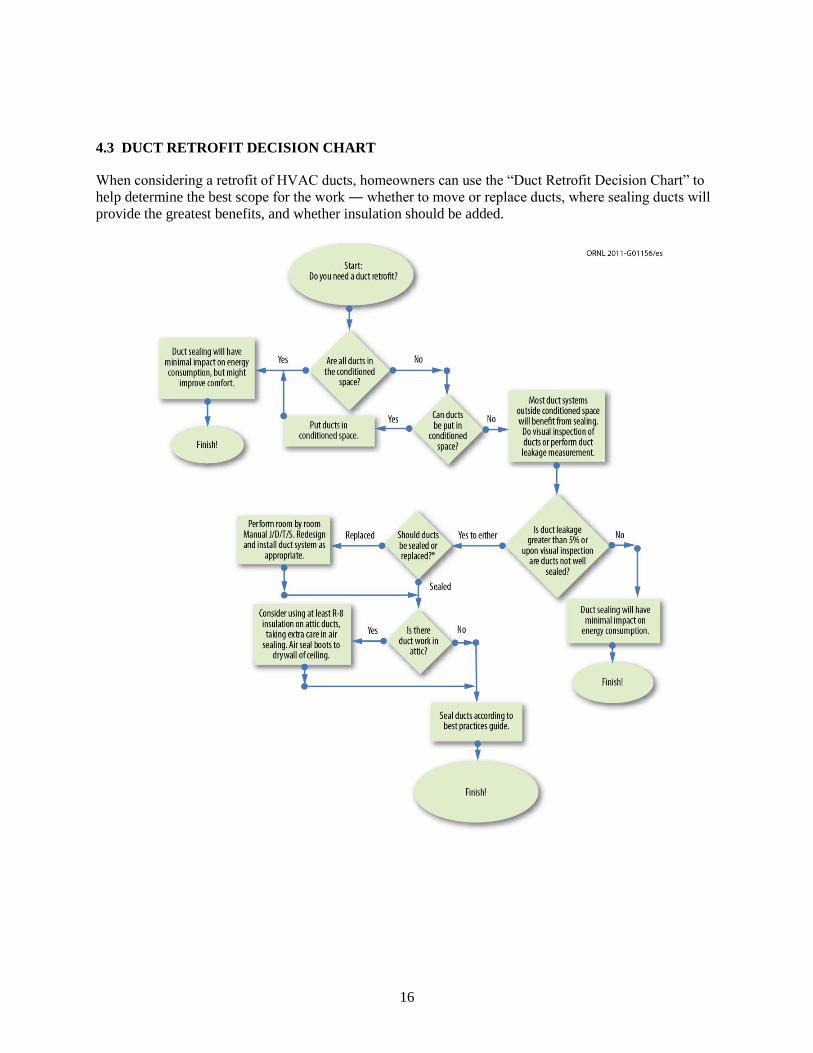
4.3 DUCT RETROFIT DECISION CHART
When considering a retrofit of HVAC ducts, homeowners can use the “Duct Retrofit Decision Chart” to
help determine the best scope for the work ― whether to move or replace ducts, where sealing ducts will
provide the greatest benefits, and whether insulation should be added.

17
Figure 9. This duct retrofit decision chart can help homeowners and professionals determine whether a
duct retrofit is needed, where sealing ducts will provide the greatest benefits, and whether insulation should
be added around ducts.*
4.4 GENERAL BEST PRACTICES
These general best practices for duct retrofits in the mixed-humid climate are based on ORNL’s
observations in ten research houses undergoing retrofits and/or comprehensive research and monitoring,
as well as the best available knowledge in the field, gathered from DOE-sponsored organizations, the U.S.
EPA, and others (as cited). These best practices are given below and specific best practices for flexible
and galvanized steel ducts, fiberglass duct board, and wall or floorboard joist cavities used as ducts are
also presented.
4.4.1 Threshold Leakage for Duct Sealing
According to the Building America Builder’s Challenge (BA 2008) duct leakage to the outside at 25 Pa
compared to the conditioned floor area should not be more than 5%. The Building Performance Institute
(BPI) recommends that duct sealing measures should be taken if the duct leakage to the outside at 25 Pa
divided by the air handler flow is greater than 10% (BPI 2007).
4.4.2 Make Sure Ducting is Sized Right
Use ANSI/ACCA Manual J 8th edition and Manual D 3
rd edition before duct sealing to determine whether
the HVAC system(s), including AC units as well as supplies to each room and return ducts, are sized right
(Rutkowski 2009).
4.4.3 Preparation
HVAC units should not be run just before or during duct sealing, because cold metal ducts can
accumulate condensation in humid areas such as the crawl space. Ducts must be clean and free from
condensation for sealants to bond effectively and for duct sealing to be successful.
4.4.4 Repair Largest Holes First
Repair largest holes or leaks first, such as those caused by disconnected branch ducts (EPA 2009). On
gaps and holes larger than 1/8 inch use fiberglass mesh tape and mastic (Jones and Klahn 2003). Leaks
closest to the air handler should be repaired first since this is where the highest duct pressure is located.
4.4.5 Insulate Ducts in Unconditioned Spaces
It is very important to insulate ducts well in vented attics and crawl spaces. This is because a typical
vented attic can reach 130°F during the summer, when the air moving through the ducts is at about 55°F.
During the winter, air temperatures in vented crawl and attic spaces in the mixed-humid climate can get
close to freezing while the air going through the ducts can be close to 120°F. To combat these energy
losses, it is beneficial to have at least R-8 insulation on ducts in unconditioned attics and crawl spaces
(IBS Advisors 2007). Consider burying attic ducts under spray foam and then blown-in insulation.
4.4.6 Using Tape or Mastic
Use water-based mastic for air-sealing in EVERY situation. Even butyl rubber/mastic tape becomes less
effective after 78 years (IBS Advisors 2007).
* Deciding whether ducts should be sealed or replaced is best left to a trained HVAC technician. If the ducts are in
such bad shape that it would be cheaper to replace them than seal them, then the ducts should be replaced.
18
If tape is used for some reason, ducts must be clean, dry, and free from dust before sealing (Building
Science Corporation 2011). Less stringent surface preparation is required when liquid mastic is used,
which is one of the reasons it is preferred, especially in retrofit situations.
Let liquid mastic dry per manufacturer’s instructions before turning HVAC system on, typically for 12
hours or more (RCD Corporation 2008).
Do not use mastic as a means of mechanical fastening. Sheet metal ductwork should be connected with
screws, flex duct with tie wraps, and fiber duct board with approved tape. For all three types of ducting
use mastic in conjunction with mechanical fastening for air-sealing (IBS Advisors 2007).
4.4.7 Protect Yourself From Hazards
If using liquid mastic inside, carefully read the material safety data sheets for the products being used.
(An example can be seen at http://www.hardcast.com/reference/msdsfiles/msdsDS321.pdf ). Although
inhalation hazards are low, if the concentration of fumes is too high it can cause nausea and irritation to
the nose, throat and lungs. Water-based mastic is less irritating than petroleum- or solvent-based mastic.
Make sure the home is well ventilated during use of mastic.
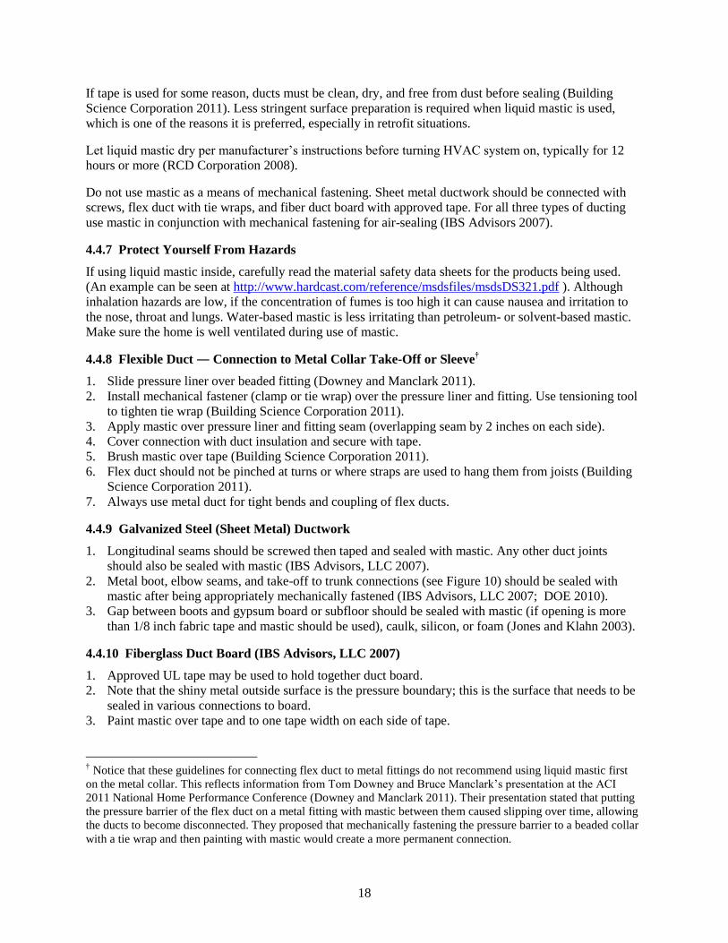
4.4.8 Flexible Duct ― Connection to Metal Collar Take-Off or Sleeve†
1. Slide pressure liner over beaded fitting (Downey and Manclark 2011).
2. Install mechanical fastener (clamp or tie wrap) over the pressure liner and fitting. Use tensioning tool
to tighten tie wrap (Building Science Corporation 2011).
3. Apply mastic over pressure liner and fitting seam (overlapping seam by 2 inches on each side).
4. Cover connection with duct insulation and secure with tape.
5. Brush mastic over tape (Building Science Corporation 2011).
6. Flex duct should not be pinched at turns or where straps are used to hang them from joists (Building
Science Corporation 2011).
7. Always use metal duct for tight bends and coupling of flex ducts.
4.4.9 Galvanized Steel (Sheet Metal) Ductwork
1. Longitudinal seams should be screwed then taped and sealed with mastic. Any other duct joints
should also be sealed with mastic (IBS Advisors, LLC 2007).
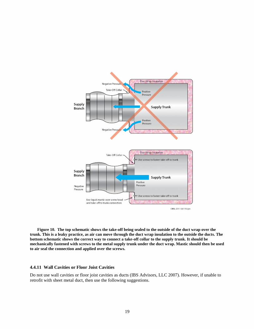
2. Metal boot, elbow seams, and take-off to trunk connections (see Figure 10) should be sealed with
mastic after being appropriately mechanically fastened (IBS Advisors, LLC 2007; DOE 2010).
3. Gap between boots and gypsum board or subfloor should be sealed with mastic (if opening is more
than 1/8 inch fabric tape and mastic should be used), caulk, silicon, or foam (Jones and Klahn 2003).
4.4.10 Fiberglass Duct Board (IBS Advisors, LLC 2007)
1. Approved UL tape may be used to hold together duct board.
2. Note that the shiny metal outside surface is the pressure boundary; this is the surface that needs to be
sealed in various connections to board.
3. Paint mastic over tape and to one tape width on each side of tape.
† Notice that these guidelines for connecting flex duct to metal fittings do not recommend using liquid mastic first
on the metal collar. This reflects information from Tom Downey and Bruce Manclark’s presentation at the ACI
2011 National Home Performance Conference (Downey and Manclark 2011). Their presentation stated that putting
the pressure barrier of the flex duct on a metal fitting with mastic between them caused slipping over time, allowing
the ducts to become disconnected. They proposed that mechanically fastening the pressure barrier to a beaded collar
with a tie wrap and then painting with mastic would create a more permanent connection.
19
Figure 10. The top schematic shows the take-off being sealed to the outside of the duct wrap over the
trunk. This is a leaky practice, as air can move through the duct wrap insulation to the outside the ducts. The
bottom schematic shows the correct way to connect a take-off collar to the supply trunk. It should be
mechanically fastened with screws to the metal supply trunk under the duct wrap. Mastic should then be used
to air seal the connection and applied over the screws.
4.4.11 Wall Cavities or Floor Joist Cavities
Do not use wall cavities or floor joist cavities as ducts (IBS Advisors, LLC 2007). However, if unable to
retrofit with sheet metal duct, then use the following suggestions.
20
1. Seal all joints/seams, etc., with mastic or silicone caulk. These joints include those between metal
joist space end caps and framing or floor, and between studs and any blocking that make up return
cavities (Jones and Klahn 2003).
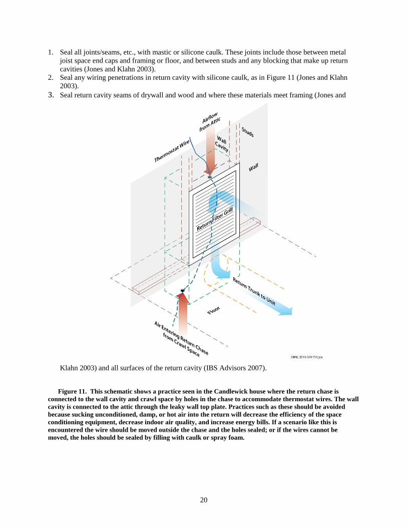
2. Seal any wiring penetrations in return cavity with silicone caulk, as in Figure 11 (Jones and Klahn
2003).
3. Seal return cavity seams of drywall and wood and where these materials meet framing (Jones and
Klahn 2003) and all surfaces of the return cavity (IBS Advisors 2007).
Figure 11. This schematic shows a practice seen in the Candlewick house where the return chase is
connected to the wall cavity and crawl space by holes in the chase to accommodate thermostat wires. The wall
cavity is connected to the attic through the leaky wall top plate. Practices such as these should be avoided
because sucking unconditioned, damp, or hot air into the return will decrease the efficiency of the space
conditioning equipment, decrease indoor air quality, and increase energy bills. If a scenario like this is
encountered the wire should be moved outside the chase and the holes sealed; or if the wires cannot be
moved, the holes should be sealed by filling with caulk or spray foam.

21
22
6. REFERENCES
Aeroseal, LLC. 2011. Aeroseal: Certified Duct Diagnostics and Sealing. (Company Website).
http://www.aeroseal.com/ (August 23, 2011).
Air Quality Sciences, Inc. 2006. “Energy Conservation and Indoor Air Quality: Partnering to Protect
Public Health.” http://www.aerias.org/uploads/EnergyConservationandIAQ.pdf.
Building America (BA). 2008. “Builders Challenge Quality Criteria Guide – Version 1.3.”
http://www1.eere.energy.gov/buildings/challenge/pdfs/bcqc_version_1_3_060408.pdf#page=6.
Building Performance Institute (BPI). 2007. “Technical Standard for the Heating Professional.”
http://www.bpi.org/Web%20Download/BPI%20Standards/Heating%20Professional_11-20-07.pdf.
Building Science Corporation. 2011. “BSC Information Sheet 603: Duct Sealing for All Climates.”
http://www.buildingscience.com/documents/information-sheets/information-sheet-duct-
sealing/files/bscinfo_603_duct_sealing.pdf (October 26, 2011).
Consortium for Advanced Residential Buildings (CARB), Steven Winter Associates, Inc. 2009. “Still
Placing Ducts in the Attic? Consider Burying Them.” http://www.carb-
swa.com/articles/guidelines/Buried%20Ducts_updated%203_17_2009.pdf.
DOE. 2010. Building America Best Practices Series: Vol. 10 ― Retrofit Techniques & Technologies: Air
Sealing ― A Guide for Contractors to Share with Homeowners, PNNL-19284, U.S. DOE,
Washington, D.C.
http://apps1.eere.energy.gov/buildings/publications/pdfs/building_america/ba_airsealing_report.pdf.
Downey, Tom, and Bruce Manclark. 2011. “Duct Repairing and Sealing.” Presentation at ACI National
Home Performance Conference, March 31, 2011.
http://2011.acinational.org/sites/default/files/session/81056/aci11hc5downeytom.pdf (October 26,
2011).
Energy Conservatory, The. 2011. “Minneapolis Duct Blaster® Operation Manual.”
http://www.energyconservatory.com/download/dbmanual.pdf (October 31, 2011).
[EPA] U.S Environmental Protection Agency. 2009. “Duct Sealing.” EPA 430-F-09-050 February 2009.
http://www.energystar.gov/ia/products/heat_cool/ducts/DuctSealingBrochure04.pdf.
Example Liquid Mastic MSDS Sheet. http://www.hardcast.com/reference/msdsfiles/msdsDS321.pdf
(August 23, 2011).
IBS Advisors, LLC. 2007. “Ductwork: A Guide to Proper Installation and Sealing.”
http://www.ibsadvisorsllc.com/_library/Ductwork.pdf.
Jackson, Roderick K., Eyu-Jin Kim, Sydney Roberts, and Robert Stephenson. 2011. Advancing
Residential Retrofits in Atlanta (draft). U.S. DOE Office of Energy Efficiency & Renewable
Energy, Building America Program.
Jones, Don Michael, and Robert Klahn. 2003. “Best Practice – Duct Sealing Overview.” Energy Designed
Homes, http://www.energydesignedhomes.com/Papers/DuctSealing.pdf.
23
Kissock, J. Kelly, Jeff S. Haberl, and David E. Claridge. 2004. “RP-1050 – Development of a Toolkit for
Calculating Linear, Change-Point Linear and Multiple-Linear Inverse Building Energy Analysis
Models.” ASHRAE. http://rp.ashrae.biz/researchproject.php?rp_id=479.
Lawrence Berkeley Laboratory (LBL). 1999. “Duct Sealant Longevity: Can duct tape take the heat?”
http://ducts.lbl.gov/ducttape/index.html.
Lawrence Berkeley National Laboratory (LBNL). 2011. “Aerosol Duct Sealing.”
http://eetd.lbl.gov/l2m2/aerosol.html (August 23, 2011).
Lawrence Berkeley National Laboratory (LBNL). 2001. “California’s Duct Opportunity.”
http://ducts.lbl.gov/calducts.htm.
RCD Corporation. 2008. “#8 Mastic Low to High Velocity Air Duct Sealant [Specifications],” RCD
Corporation Makes Home Weatherization Easy, http://rcdmastics.com/images/stories/pdf/8pds.pdf
(October 26, 2011).
Rutkowski, Hank. 2009. Manual D, Residential Duct Systems, Third Edition, Version 1.00, ANSI/ACCA
Manual D- 2009, ISBN #1-892765-50-0.
Vineyard, E.A., R.A. Linkous, and E. Baskin. 2003. “Measured Performance of Conventional and High-
Velocity Distribution Systems in Attic and Space Locations.” ASHRAE Transactions 109(2):45-51.
Yingling, Ronald K., Donald F. Luebes, and Ralph J. Johnson. 1981. Residential Duct Systems: Selection
and Design of Ducted HVAC Systems. Home Builder Press: Washington DC.
http://www.toolbase.org/PDF/DesignGuides/residential_duct_systems.pdf.