case study 1: unix and linux -...
TRANSCRIPT

1
Wireless networks

2
Overview
• Wireless networks basics
• IEEE 802.11 (Wi-Fi) a/b/g/n
• ad Hoc MAC protocols
• ad Hoc routing DSR AODV

3
Wireless Networks
• Autonomous systems of mobile hosts connected by
wireless links
• Nodes are autonomous and independent
– mobile, battery powered
– communicate mainly via radio frequncies
• Two modes of operations
– wireless networking with a base station:
• wired access points
– ad hoc networking:
• no centralized coordinators

4
Wireless networking with a BS
Basestation
To wired network

5
Wireless networking with a BS (2)
Basestation
To wired network
Intracell
communication
s
d

6
Wireless networking with a BS (3)
Basestation
Intercell
communication
s
d
Basestation

7
Ad hoc networking

8
Ad hoc networking (2)
s
d

9
Ad hoc networking (3)
s
d

10
Ad hoc networking (4)
s
dMultihop
communication

11
Wireless networks: challanges• Limited knowledge
– a terminal cannot head all the others
– multipath fading effects
• Mobility/Failure of terminals
– terminals move in the range of different BS
– terminals move away from each other
• Limited terminals
– battery life, memory, processing and transmission range
• Privacy
– eavesdropping of ongoing communications

12
Wireless networks: some problems
• Access to a shared wireless channel
– CSMA/CD cannot be used
– hidden-exposed terminal problem
• Hand-off
– moving a terminal into the range of a different BS
• Routing
– deciding a path from source to destination in multi
hop networks
– dealing with arbitrary changes in neighborhood
13
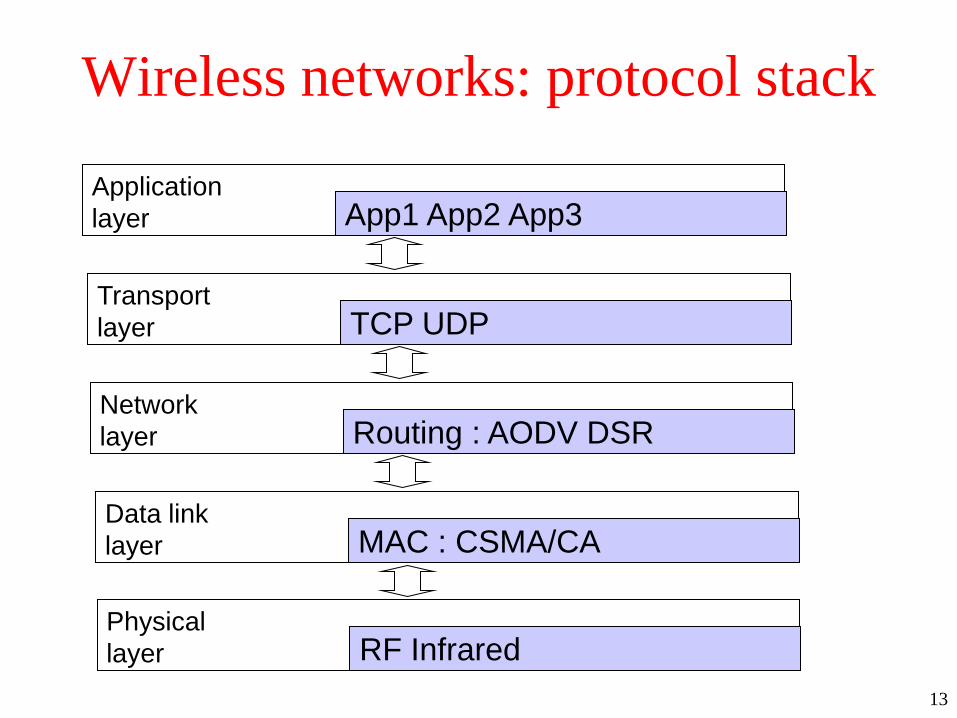
Wireless networks: protocol stack
App1 App2 App3Application
layer
TCP UDPTransport
layer
Routing : AODV DSRNetwork
layer
MAC : CSMA/CAData link
layer
RF InfraredPhysical
layer

14
Wired networks MAC protocols
• Basic assumptions:
– a single channel is available for all communications
– all stations can transmit on it and receive from it
– if frames are send simultaneously on the channel
the resulting segnal is garbles (a collision)
– all stations can detect collisions
• Different protocols
– ALOHA, slotted ALOHA, CSMA, CSMA/CD

15
CSMA/CD
• Carries Sense Multiple Accesses with Collision
Detection
• Basic idea of CSMA:
– When a station has a frame to send listens to the
channel to see if anyone else is transmitting
– if the channel is busy, the station waits until it
becomes idle
– when channel is idle, the station transmits the frame
– if a collision occurs the station waits a random
amount of time and repeats the procedure.

16
CSMA/CD (2)
• CSMA with Collision Detection
– a station aborts its transmission as soon as it detects
a collision
• if two stations sense the channel idle simultaneously and
start transmitting, they quickly abort the frame as soon as
collision is detected
– it is widely used on LANs in MAC sub-layer
– IEEE 802.3 Ethernet

17
CSMA/CD (3)
• CSMA/CD behavior
Frame
transmission
period
Frame Frame
contention
period
idle
period
contention
slot (2*T)

18
Binary Exponential Backoff
• Used in IEEE 802.3
• Time after a collision is divided in contention slots
– length of a contention slot is equal to worst case round
propagation time (2T if T is the time to reach the most
distant stations)
• After the first collision
– each station waits 0 or 1 slot before trying again

19
Binary Exponential Backoff (2)
• After collision i
– chooses x at random in 0, 1, 2, …,2i-1
– skips x slots before retrying
• After 10 collisions:
– the randomization interval is frozen at 0..1023
• After 16 collisions
– failure is reported back to upper levels

20
Wireless networks: MAC
• Hidden terminal problem
– what matters is interference at the receiver not at the
sender
21
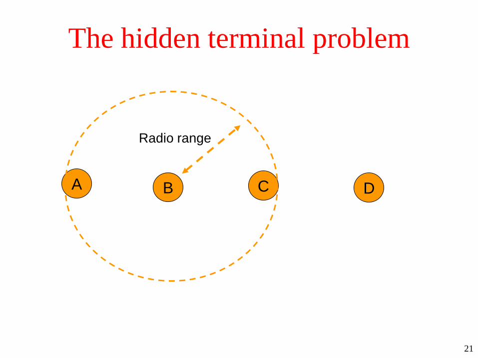
The hidden terminal problem
A CB D
Radio range

22
The hidden terminal problem (2)
A CB D
A is sending to B

23
Hidden terminal problem (3)
A CB D
A is sending to B
C senses the medium: it will NOT hear A, out of range

24
Hidden terminal problem (4)
A CB D
A is sending to B
C senses the medium: it will NOT hear A, out of range
C starts to sent to B -- COLLISION OCCURS at B

25
Wireless networks: MAC
• Hidden terminal problem
– what matters is interference at the receiver not at the
sender
– in the example: C is not able to detect a potential
competitor because it is out of range and collision
happens at B (the receiver)
• Exposed terminal problem
– a station can hear a transmission and be able to transmit
without interfere with it

26
The exposed terminal problem
A CB D
1. B is transmitting to A, C wants to transmit to D

27
The exposed terminal problem (2)
A CB D
1. B is transmitting to A, C wants to transmit to D
2. C senses the medium,
hears B and concludes: cannot transmit to D

28
The exposed terminal problem (3)
A CB D
1. B is transmitting to A, C wants to transmit to D
2. C senses the medium, concludes: cannot transmit to D
3. The two transmissions can actually happen in parallel.
Interference zone

29
Wireless networks: MAC (2)
• what matters is interference at the receiver not at
the sender
– this cannot be established sensing the carrier at the
sender
• Multiple transmissions can occur simultaneously if
destinations are out of range of each other
– a station can hear a transmission and be able to transmit
without interfere with it
• Need different MAC protocols from wired LANs

30
The MACA protocol
• Multiple Accesses with Collision Avoidance
• Basic idea:
– stimulate the receiver into transmitting a short frame
– then transmitting a (long) data frame
– stations hearing the short frame refrain from
transmitting during the transmission of the subsequent
data frame

31
The MACA protocol
C BA D
C is within range of A but not within range of B and D
D is within range of B but not within range of A and C
E is within range of both A and B
E

32
The MACA protocol (2)
C BA D
1. A wants to transmit to B, sends a Request To Send to B
E
RTS
33
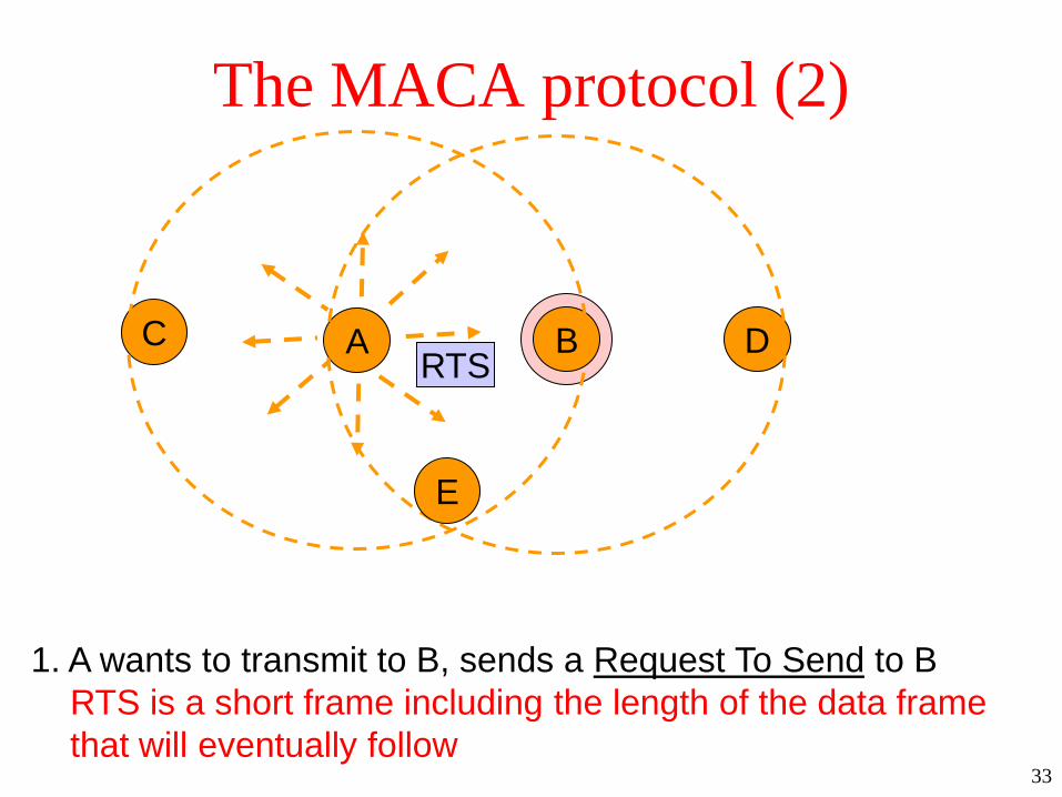
The MACA protocol (2)
C BA D
1. A wants to transmit to B, sends a Request To Send to B
RTS is a short frame including the length of the data frame
that will eventually follow
E
RTS

34
The MACA protocol (3)
C BA D
1. A wants to transmit to B, sends an RTS to B
E
RTS

35
The MACA protocol (4)
C BA D
1. A wants to transmit to B, sends an RTS to B
2. If B wants to receive the message replies with a Clear To Send
CTS is a short frame with data length copied from RTS
E
CTS

36
The MACA protocol (5)
C BA D
1. A wants to transmit to B, sends an RTS to B
2. If B wants to receive the message replies with a CTS
E
CTS
37
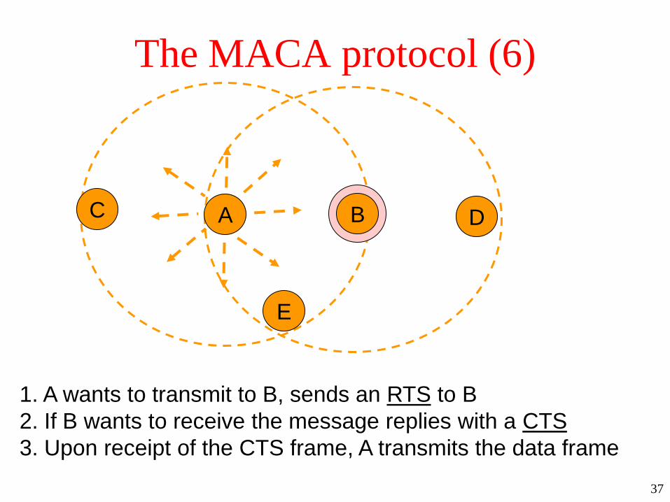
The MACA protocol (6)
C BA D
1. A wants to transmit to B, sends an RTS to B
2. If B wants to receive the message replies with a CTS
3. Upon receipt of the CTS frame, A transmits the data frame
E
38
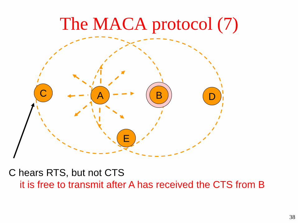
The MACA protocol (7)
C BA D
C hears RTS, but not CTS
it is free to transmit after A has received the CTS from B
E

39
The MACA protocol (8)
C BA D
D hears CTS, but not RTS
it should stay silent until data frame transmission completes
E

40
The MACA protocol (9)
C BA D
D hears CTS and RTS
it should stay silent until data frame transmission completes
E

41
The MACA protocol: collisions
C BA D
C and B send RTS simultaneously to A
E
RTS
RTS

42
The MACA protocol: collisions (2)
C BA D
C and B send RTS simultaneously to A
The two messages collide
No CTS is generated
E
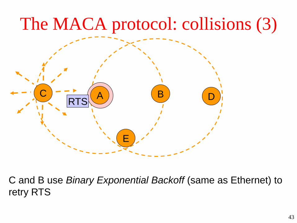
43
The MACA protocol: collisions (3)
C BA D
C and B use Binary Exponential Backoff (same as Ethernet) to
retry RTS
E
RTS

44
MACAW: MACA for Wireless
• Fine tunes MACA to improve performance
– introduces an ACK frame to acknowledge a successful
data frame
– added Carrier Sensing to keep a station from
transmitting RTS when a nearby station is also doing so
to the same destination
– exponential backoff is run for each separate pair
source/destination and not for the single station
– mechanisms to exchange information among stations
and recognize temporary congestion problems
– CSMA/CA used in IEEE 802.11 is based on MACAW

45
IEEE 802.11 family
• IEEE 802.11 (Legacy mode)
– First released in 1997 and clarified in 1999
– rarely used today
– 1-2 Mbps data rate implemented via
• infrared (IR) signals,
• radio frequencies in the 2.4GHz band (ISM -- Industrial
Scientific Medical Frequency band)
– many degrees of freedom: interoperability was
challenging among different products
– rapidly supplemented (and popularized) by 802.11b
– most used today 802.11a/b/g emerging 802.11n

46
IEEE 802.11 family (2)
• IEEE 802.11b
– Released 1999
– Operating frequency: 2.4GHz band (ISM band)
• potential interference with other appliances : cordless
telephones, microwave ovens etc
– Throughput (typ): 4.3 Mbps
– Data rate (max): 11 Mbps
– Modulation technique: DSSS
47
IEEE 802.11 family (3)
• IEEE 802.11a
– Released 1999
– Operating frequency: 5 GHz band (Unlicensed
National Information Infrastructure U-NII band)
– Throughput (typ): 23 Mbps
– Data rate (max): 54 Mbps
– Modulation technique: OFDM

48
IEEE 802.11 family (4)
• IEEE 802.11g
– Released 2003
– Operating frequency: 2.4GHz band (ISM band)
– Throughput (typ): 19 Mbps
– Data rate (max): 54 Mbps
– Modulation technique: OFDM
49
IEEE 802.11 family (5)
• IEEE 802.11n
– To be released 2009
– Operating frequency: 2.4GHz band and 5GHz band
– Throughput (typ): 74 Mbps
– Data rate (max): 248 Mbps
– Modulation technique: MIMO using multiple
antennas

50
IEEE 802.11: protocol stack
Upper
Layers
Logical Link Control
MAC Sublayer
Data link
layer
Physical
layer
802.11g
OFDM
802.11b
HR-
DSSS
802.11a
OFDM802.11n
MIMO802.11
legacy

51
IEEE 802.11: Architecture
• A group of stations operating under a given
coordination function
– may use or not a base station (Access Point)
– is using APs a station communicates with another
channeling all the traffic through a centralized AP
– AP can provide connectivity with other APs and other
groups of stations via fixed infrastructure
52
IEEE 802.11: Architecture (2)
• Supports ad hoc networks
the IEEE 802.11 view
a group of stations that are under the direct control of a
single coordination function without the aid of an
infrastructure network
– a station can communicate directly with another
without channeling all the traffic through AP

53
The physical layer
• All techniques make it possible to deliver a
MAC frame from one station to another
• Technology used and speed differ
• We give a short list of keyword

54
The physical layer: IR
• Features:
– Diffused transmission at 0.85-0.95 microns
– Two speeds: 1Mbps 2Mbps
– encoding gray code
• at 1Mbps : 4 bits on 16 bits containing fifteen 0s and a
single 1
• at 2Mbps : 2 bits on 4 bits 0001,0010,0100, 1000
– cannot penetrate walls, swamped by sun
– not very popular

55
The physical layer: FHSS
• Frequency Hopping Spread Spectrum
– 79 channels, 1MHz wide each starting at the low end of
the 2.4 GHz
– bandwidth: 1MBps
– Frequency hopping
• pseudo-random generator drives hopping
• same seed on all stations, synchronization
• dwell time (time spent in each frequency) less than 400msec
• makes eavesdropping harder
• solves multipath fading over long distances

56
The physical layer: DSSS
• Discrete Sequence Spread Spectrum
– bandwidth: 1-2MBps
– ?????

57
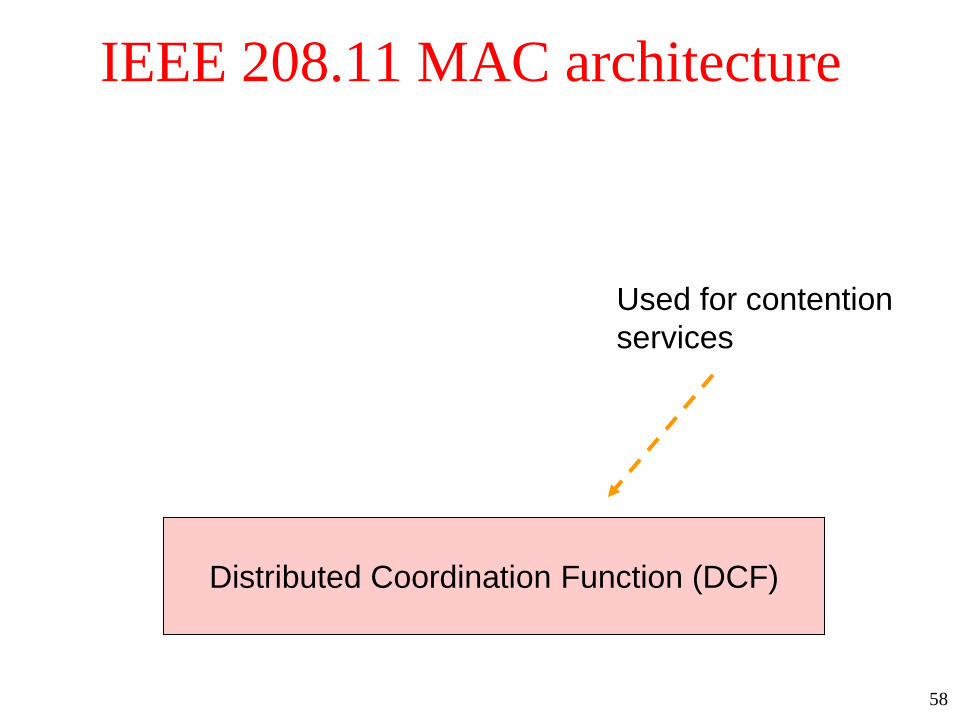
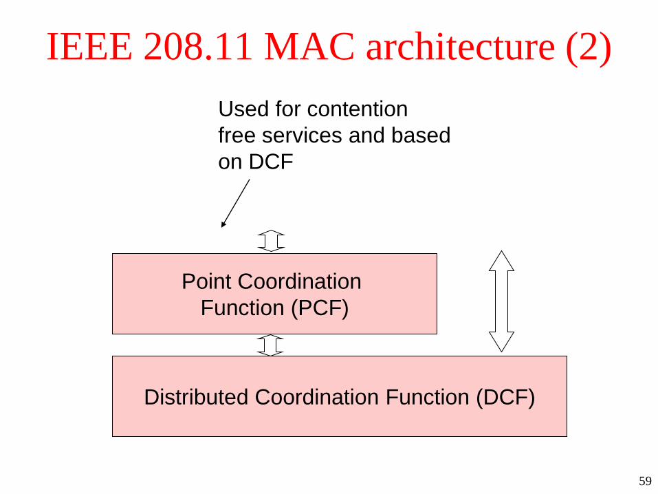
IEEE 802.11:MAC Sublayer• Two modes of operations:
– DCF : Distributed Coordination Function
• completely decentralized
• thought for best effort asynchronous traffic
– PCF : Point Coordination Function
• uses base station to control all activity in its cell
• thought for delay-sensitive traffic
• BS polls stations to ask for transmissions
• based on DCF
• DCF must be implemented by all stations
• DCF and PCF can be active at the same time in
the same cell
58
IEEE 208.11 MAC architecture
Distributed Coordination Function (DCF)
Used for contention
services
59
IEEE 208.11 MAC architecture (2)
Distributed Coordination Function (DCF)
Point Coordination
Function (PCF)
Used for contention
free services and based
on DCF

60
IEEE 802.1: DCF
• Must be implemented by all stations
• Completely decentralized
• Best effort asynchronous traffic
• Stations must contend for the channel for each
frame
– using CSMA/CA

61
IEEE 802.1: DCF (2)• Carrier sensing is performed at two levels:
– physical CS
• detects the presence of other IEEE 802.11 WLAN users by
analyzing all the detected packets
• detects any activity in the channel due to other sources
– virtual CS
• performed sending duration information in the header of an
RTS, CTS and data frame
• duration information is used to adjust station’s NAV (network
allocation vector) that indicates channel busy and the time that
must elapse before sampling again the channel for idle status
– A channel is marked busy if either the physical or the
virtual CS indicate busy
62
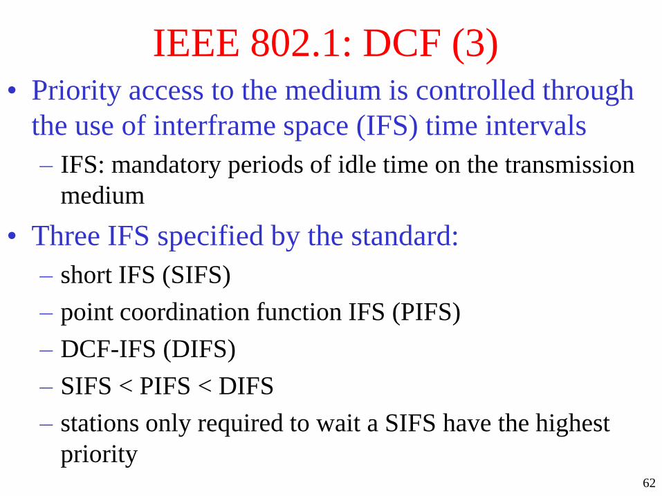
IEEE 802.1: DCF (3)• Priority access to the medium is controlled through
the use of interframe space (IFS) time intervals
– IFS: mandatory periods of idle time on the transmission
medium
• Three IFS specified by the standard:
– short IFS (SIFS)
– point coordination function IFS (PIFS)
– DCF-IFS (DIFS)
– SIFS < PIFS < DIFS
– stations only required to wait a SIFS have the highest
priority

63
DCF basic access method
source
destination
other
Senses channel idle and waits for DIFS

64
DCF basic access method (2)
source
destination
other
If idle starts transmitting data
DIFS
65
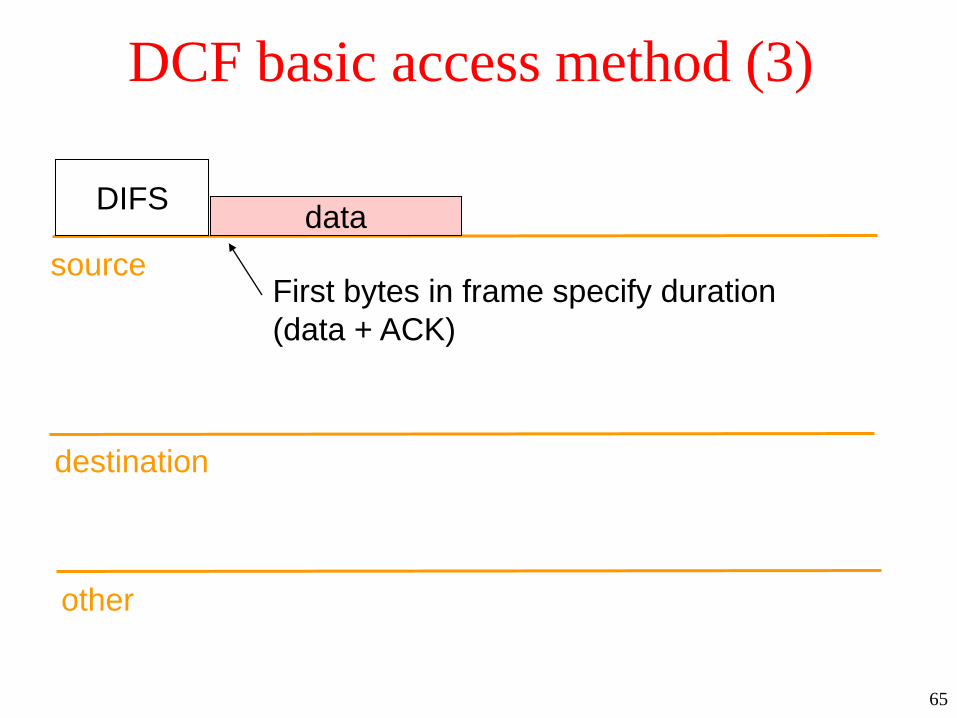
DCF basic access method (3)
source
destination
other
First bytes in frame specify duration
(data + ACK)
dataDIFS

66
DCF basic access method (3)
source
destination
other
First bytes in frame specify duration
(data + ACK)
dataDIFS
NAV
Hearing duration
sets NAV for virtual CS

67
DCF basic access method (4)
source
destination
other
dataDIFS
ACKSIFS
Waits SIFS before ack
successful transmission
NAV

68
DCF basic access method (5)
source
destination
other
dataDIFS
ACKSIFS
DIFS
Stations must
again wait DIFS
before transmitting
NAV
69
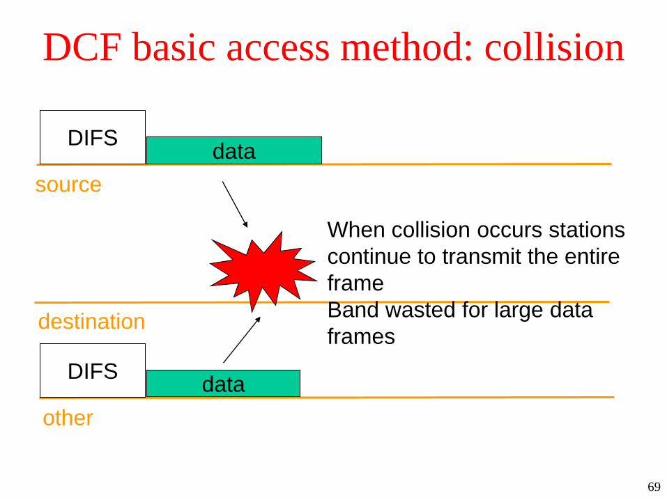
DCF basic access method: collision
source
destination
other
dataDIFS
data
When collision occurs stations
continue to transmit the entire
frame
Band wasted for large data
frames
DIFS

70
DCF basic access method: collision (2)
source
destination
other
dataDIFS
dataBackoff to resend
Backoff to resend
DIFS

71
DCF RTS/CTS
source
destination
other
RTSDIFS
NAV/RTS
ACKSIFS
20 bytes
CTS
data
SIFS
NAV/CTS
SIFS
NAV/data
14 bytes

72
DCF: RTS/CTS• Three choices:
– never use RTS/CTS: lightly loaded medium
– use RTS/CTS for long messages: when length exceeds RTS_Threshold
– always use RTS/CTS

73
DCF: Fragmentation• Fragmentation of large data frames may improve
reliability:
– performed only if data is larger than
Fragmentation_Theshold (size of each fragment except
last)
– all fragments are sent in sequence
– channel is not released until the complete data has been
transmitted or the source station fails to receive an
acknowledgement for the transmitted fragment

74
DCF Fragmentation (2)
source
destination
other
Frag0SIFS
NAV/RTS/CTS
ACK1SIFS
NAV/Frag0
ACK0SIFS
Frag1SIFS
NAV/Frag1

75
DCF: Fragmentation (3)– When an ACK is not received in time, the source station
re-contends the channel
– after getting the channel again it starts from the last
unacknowledged fragment
– if RTS/CTS is used the duration in RTS/CTS account
only for the transmission of the first fragment
– the subsequent duration information are extracted in the
duration information of each fragment
76
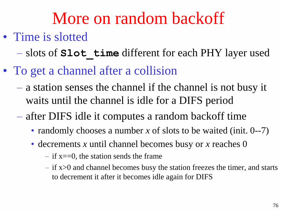
More on random backoff• Time is slotted
– slots of Slot_time different for each PHY layer used
• To get a channel after a collision
– a station senses the channel if the channel is not busy it
waits until the channel is idle for a DIFS period
– after DIFS idle it computes a random backoff time
• randomly chooses a number x of slots to be waited (init. 0--7)
• decrements x until channel becomes busy or x reaches 0
– if x==0, the station sends the frame
– if x>0 and channel becomes busy the station freezes the timer, and starts
to decrement it after it becomes idle again for DIFS
77
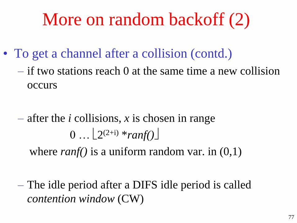
More on random backoff (2)
• To get a channel after a collision (contd.)
– if two stations reach 0 at the same time a new collision
occurs
– after the i collisions, x is chosen in range
0 … 2(2+i) *ranf()
where ranf() is a uniform random var. in (0,1)
– The idle period after a DIFS idle period is called
contention window (CW)

78
IEEE 802.11: Frames
• Three types of frames:
– management: station association/disassociation with
the AP, synchronization, authentication
– control: handshaking and acknowledgement
– data: data transmission, can be combined with polling
and ACK in PCF

79
IEEE 802.11: Frame format
Frame
control
Duration
conn
ID
2 2bytes
Addr Addr Addr Seq Addr Data CRC
6 6 6 6 0--2312 42
Prot.
Vers.Type
2 2
Sub-
type
To
DS
From
DS
Last
FragRetry
Power
mgt
More
data
4 1 1 1 1 11bits
W O
1 1
Version: more than one protocol can coexist
in the same cell

80
IEEE 802.11: Frame format (2)
Frame
control
Duration
conn
ID
2 2bytes
Addr Addr Addr Seq Addr Data CRC
6 6 6 6 0--2312 42
Prot.
Vers.Type
2 2
Sub-
type
To
DS
From
DS
Last
FragRetry
Power
mgt
More
data
4 1 1 1 1 11bits
W O
1 1
Type of the frame:
management, control, data
Subtype of the frame:
eg. RTS, CTS,ACK

81
IEEE 802.11: Frame format (3)
Frame
control
Duration
conn
ID
2 2bytes
Addr Addr Addr Seq Addr Data CRC
6 6 6 6 0--2312 42
Prot.
Vers.Type
2 2
Sub-
type
To
DS
From
DS
Last
FragRetry
Power
mgt
More
data
4 1 1 1 1 11bits
W O
1 1
Is the frame going to or coming from the intercell
distribution system?
eg. To/From Ethernet interconnecting AS

82
IEEE 802.11: Frame format (4)
Frame
control
Duration
conn
ID
2 2bytes
Addr Addr Addr Seq Addr Data CRC
6 6 6 6 0--2312 42
Prot.
Vers.Type
2 2
Sub-
type
To
DS
From
DS
More
FragRetry
Power
mgt
More
data
4 1 1 1 1 11bits
W O
1 1
More fragments will follow? Marks retransmission of a
frame sent earlier

83
IEEE 802.11: Frame format (5)
Frame
control
Duration
conn
ID
2 2bytes
Addr Addr Addr Seq Addr Data CRC
6 6 6 6 0--2312 42
Prot.
Vers.Type
2 2
Sub-
type
To
DS
From
DS
More
FragRetry
Power
mgt
More
data
4 1 1 1 1 11bits
W O
1 1
Used to put the receiver into
sleep or take out from sleepSender has additional frames
for the receiver
84
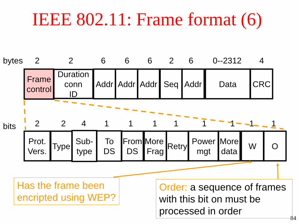
IEEE 802.11: Frame format (6)
Frame
control
Duration
conn
ID
2 2bytes
Addr Addr Addr Seq Addr Data CRC
6 6 6 6 0--2312 42
Prot.
Vers.Type
2 2
Sub-
type
To
DS
From
DS
More
FragRetry
Power
mgt
More
data
4 1 1 1 1 11bits
W O
1 1
Has the frame been
encripted using WEP?Order: a sequence of frames
with this bit on must be
processed in order

85
IEEE 802.11: Frame format (7)
Frame
control
Duration
conn
ID
2 2bytes
Addr Addr Addr Seq Addr Data CRC
6 6 6 6 0--2312 42
Time (microsecs): how long the frame/fragment and its
acknowledgement will occupy the channel

86
IEEE 802.11: Frame format (8)
Frame
ctrl
Duration
conn
ID
2 2bytes
Addr Addr Addr Seq Addr Data CRC
6 6 6 6 0--2312 42
Standard IEEE 48-bit MAC addresses:
source, destination, source and destionation AP
for inter-cell traffic

87
IEEE 802.11: Frame format (9)
Frame
ctrl
Duration
conn
ID
2 2bytes
Addr Addr Addr Seq Addr Data CRC
6 6 6 6 0--2312 42
Sequence: allows fragments
to be numbered. 12 bits identify the frame
and 4 identify fragments

88
IEEE 802.11: Frame format (10)
Frame
ctrl
Duration
conn
ID
2 2bytes
Addr Addr Addr Seq Addr Data CRC
6 6 6 6 0--2312 42
Payload + (optional) bytes
encription/decription for
WEP (Wired Equivalent Privacy)
protocol

89
IEEE 802.11: Frame format (11)
Frame
ctrl
Duration
conn
ID
2 2bytes
Addr Addr Addr Seq Addr Data CRC
6 6 6 6 0--2312 42
Cyclic Redundancy Check:
32 bit hash code of the data
for transmission error detection
(NOT recovery)

90
IEEE 802.11: PCF• Optional capability:
– connection oriented
– provides contention-free frame transfer
– acts under the control of the point coordinator (PC) that
performs polling and enables stations to transmit without
contending for the channel
– the method by which polling tables are maintained and
polling sequence is determined is left to the implementor
– it is required to coexist with DCS

91
IEEE 802.11: PCF (2)
• Starting contention-free period
– AP sends a Beacon Frame (BF)
– stations synchronize using BF
• PCF occurs periodically
– CFP_rate specifies the repetition interval
– in each repetition interval a portion of the time is allotted
for contention-free traffic and the remaining for
contention based traffic
– CFP_rate corresponds to an integral number of BF

92
IEEE 802.11: PCF (3)
• Length of PCF period
– CFP_Max_Duration determines the maximum size of a
contention free period
– AP decides the actual length, can be smaller if PCF
traffic is light or DCF traffic is heavy
93
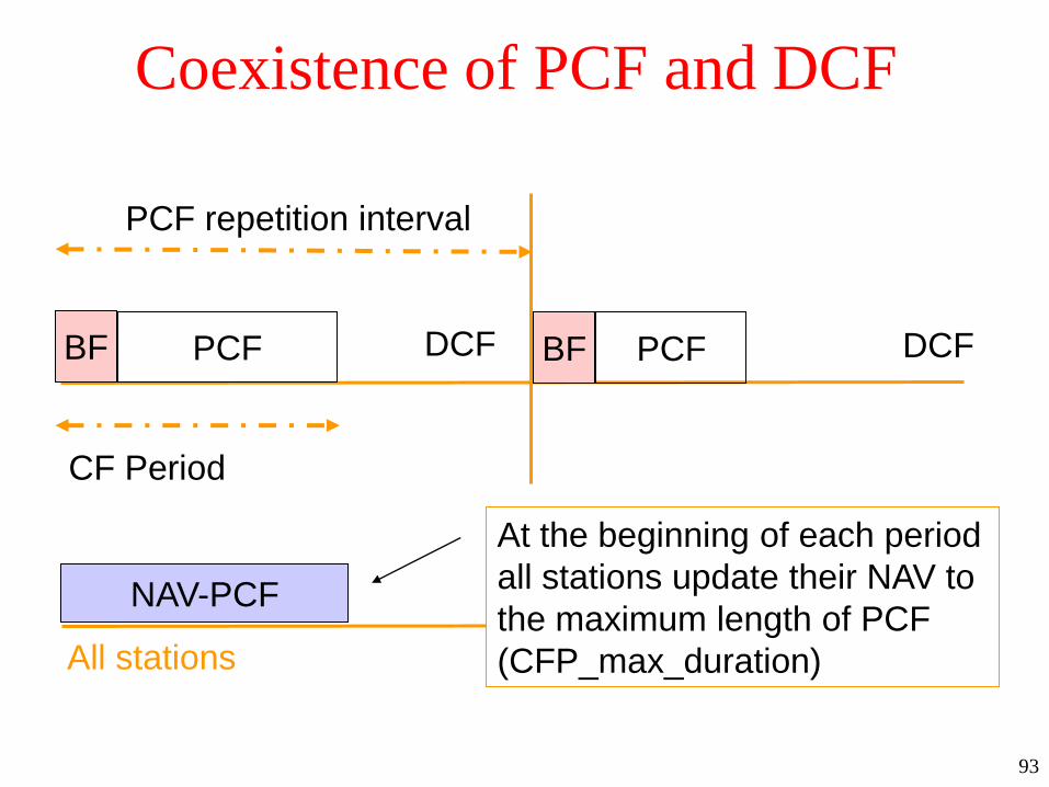
Coexistence of PCF and DCF
All stations
BF PCF DCF BF PCF DCF
PCF repetition interval
NAV-PCF
At the beginning of each period
all stations update their NAV to
the maximum length of PCF
(CFP_max_duration)
CF Period

94
Coexistence of PCF and DCF (2)
All stations
BF PCF DCF BF PCF DCF
PCF repetition interval
NAV-PCF
During PCF stations can only
respond to a poll from the PC
or for transmission of an ACK
in the SIFS after receiving a data
frame
CF Period

95
Coexistence of PCF and DCF (3)
All stations
BF PCF DCF BF PCF DCF
PCF repetition interval
NAV-PCF
PCF is always closed by PC
sending a Contention Free End
frame (CFE)
CF Period
CFE CFE

96
Running PCF
All stations
NAV-PCF
PC senses the medium. If idle
for PIFS (SIFS < PIFS < DIFS)
it sends the beacon frame
PC
PIFS BF

97
Running PCF (2)
All stations
NAV-PCF
Then waits for SIFS and sends a data
and/or CF-poll frame
PC
PIFS BF SIFS D1+poll

98
Running PCF (3)
All stations
NAV-PCF
After SIFS, the destination can send
a CF-ACK or data+CF-ACK frame
PC
PIFS BF SIFS D1+poll SIFS
U1+ACK

99
Running PCF (4)
All stations
NAV-PCF
After SIFS, the PC can send
a CF-ACK or data or CF-poll frame
PC
PIFS BF SIFS D1+poll SIFS
U1+ACK
SIFS D2+ACK+poll

10
0
Running PCF (5)
All stations
NAV-PCF
When polled a station can send
data directly to another station
PC
D1+poll SIFS
stn-to-stn SIFS ack

10
1
Running PCF (6)
All stations
NAV-PCF
PC waits PIFS following and ACK frame
to be sure transmission is finished before
polling again
PC
D1+poll SIFS
stn-to-stn
PIFS D2+poll
SIFS ack

10
2
Running PCF (7)
• With this model
– PC can decide to send to a non-PCF aware station (one
that only has DCF)
• interaction works well as this station will respond with and
ACK
– messages can be fragmented as in DCF