case study 4: wlans and aperture antennas · case study 4: wlans and aperture antennas increasing...
TRANSCRIPT

1 ECE422 / Prof. S. V. Hum
Case Study 4: WLANs and Aperture Antennas
Increasing the range of your WLAN

Agenda
• Background: WLAN standards (WiFi) • EIRP limitations • Circular waveguide theory • Design of a open-end circular waveguide
aperture • “Mod”-ing an 802.11b/g access point • Does it work?
2 ECE422 / Prof. S. V. Hum

WiFi WLAN Background • Governed by the 802.11
standard established by the Institute of Electrical and Electronics Engineers (IEEE)
• Standard describes over-the-air (OTA) modulation techniques for wireless LANs – Operating frequency – Protocol
3 ECE422 / Prof. S. V. Hum

Capacity
• Higher throughputs possible through data compression and source coding
• View of legacy channel assignments at 2.4 GHz (courtesy Wikipedia)
4 ECE422 / Prof. S. V. Hum
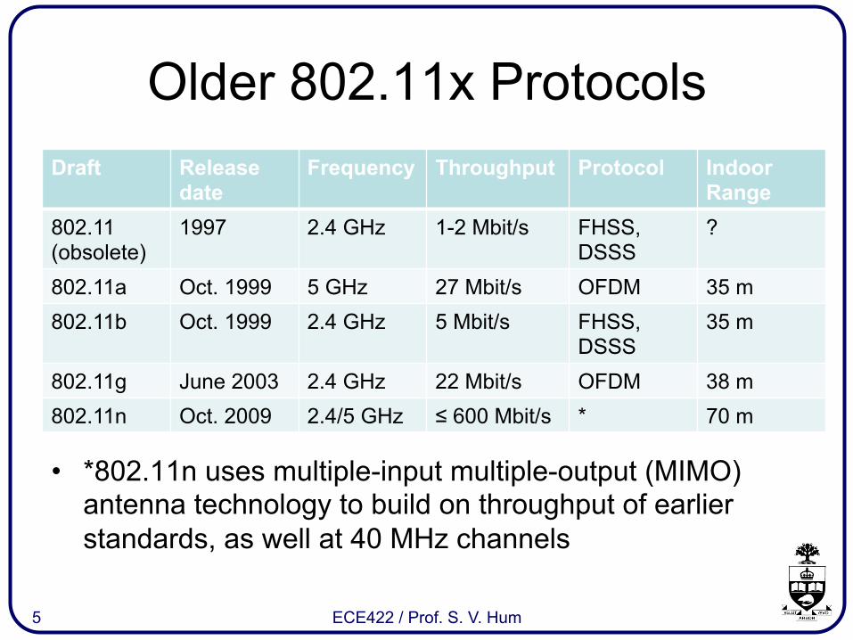
Older 802.11x Protocols Draft Release
date Frequency Throughput Protocol Indoor
Range 802.11 (obsolete)
1997 2.4 GHz 1-2 Mbit/s FHSS, DSSS
?
802.11a Oct. 1999 5 GHz 27 Mbit/s OFDM 35 m 802.11b Oct. 1999 2.4 GHz 5 Mbit/s FHSS,
DSSS 35 m
802.11g June 2003 2.4 GHz 22 Mbit/s OFDM 38 m 802.11n Oct. 2009 2.4/5 GHz ≤ 600 Mbit/s * 70 m
5 ECE422 / Prof. S. V. Hum
• *802.11n uses multiple-input multiple-output (MIMO) antenna technology to build on throughput of earlier standards, as well at 40 MHz channels

802.11ac
• Mandatory 80 MHz channels, extendable to 160 MHz
• 8 spatial MIMO streams (vs. 4 in 802.11n) • Downlink multi-user MIMO (MU-MIMO),
for handling more users • Higher spectral efficiency: 256 QAM (vs 64
QAM in 802.11n) • Single-user capacity up to 1.7 Gbps
6 ECE422 / Prof. S. V. Hum

Other Features • Many older access points
use two antennas for “diversity” combining of radio signals – For combatting fading
• Newest generation equipment uses multiple antennas for MIMO / MU-MIMO – Each TX/RX pair constitute
an “antenna stream” that is uncorrelated from other streams
7 ECE422 / Prof. S. V. Hum
Discussion on Performance
• Operation at 5 GHz gives (gave) higher throughput due to higher carrier frequency
• All things equal, the fractional bandwidth leads to higher channel bandwidths at higher carrier frequencies
• 802.11a was better for throughput reasons – 2.4 GHz ISM band also heavily congested
• 802.11b was vastly more popular due to lower hardware costs, and comparable throughputs with 802.11g extension
8 ECE422 / Prof. S. V. Hum

Range Limitations • Many objects attenuate
signals more at higher frequencies, making 2.4 GHz more preferable for indoor applications than 5 GHz
• Regardless, regulatory bodies restrict the allowable EIRP from 802.11 devices which limits the ultimate range of WLANs
9 ECE422 / Prof. S. V. Hum

Range Limitations for Mobile LANs
• Limitations to control co-channel interference • If transmit antenna gain < 6 dBi
– Maximum EIRP is 1 W (+30 dBm) – Example: 100 mW into 3 dBi antenna = 200 mW
(compliant) – Most “stock” WLAN antennas fall into this category
• If transmit antenna gain > 6 dBi – 1 dB reduction in transmit power required for each
additional 3 dB of antenna gain past 6 dBi – Thus, small increases in TX power are permissible
10 ECE422 / Prof. S. V. Hum

Custom Antennas for WLANs
• Practically we are limited in the EIRP that can be produced – Hardware (power amplifier) limitations – Physical size of aperture that would be needed
• Let’s look at a simple “homebrew” medium-gain aperture antenna
• We need: – Aperture “current” distribution, so that we can find far
field pattern – Input impedance, for matching purposes
11 ECE422 / Prof. S. V. Hum
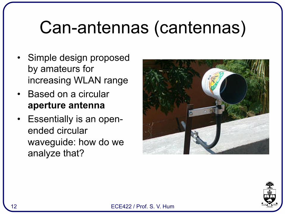
Can-antennas (cantennas) • Simple design proposed
by amateurs for increasing WLAN range
• Based on a circular aperture antenna
• Essentially is an open-ended circular waveguide: how do we analyze that?
12 ECE422 / Prof. S. V. Hum

Circular Waveguide Theory • Consider the equation
• Expanding the Laplacian,
• Solution can be expressed as a product (using separation of variables)
13 ECE422 / Prof. S. V. Hum
h2

Circular Waveguide Solutions
where Jn is a Bessel function of the first kind of nth order
14 ECE422 / Prof. S. V. Hum
• TM and TE modes are supported in circular waveguides
• We can have transverse field variation in the radial [R(r)] and the axial directions [Φ(f)]
• Mode designation: TMmn and TEmn, where m is the # of half-wave field variations in φ-direction, n is the # of half-wave field variations in the r-direction

TE11 Mode (dominant mode) • We are concerned with
the TE mode for antenna purposes
• Boundary conditions and Maxwell’s equations to find the remaining field components
• The transverse field distribution is important for computing the far-field
15 ECE422 / Prof. S. V. Hum

TE11 Mode (dominant mode) • The electric and magnetic
fields across the aperture compose “equivalent currents” in a continuous 2D array
• The Fourier transform of these equivalent currents gives the far-field pattern
16 ECE422 / Prof. S. V. Hum

Making a Cantenna 1. Get a large can of
appropriate diameter so that we are above the cutoff frequency
2. Consume the contents 3. Remove one end of the
can to form the aperture
a = 53 mm length = 180 mm
17 ECE422 / Prof. S. V. Hum
“Back of the envelope” directivity calculation: 4π/λ2 * Aap = 7.10 = 8.51 dBi
fc11 = 1.658 GHz

Making a Cantenna 4. Insert a coaxially-fed
probe a short distance away from the shorted end of the waveguide
• The location and length of the feed probe are optimized to maximize coupling into the TE11 mode
– Optimized numerically in a CAD package
– Fine-tuned experimentally
18 ECE422 / Prof. S. V. Hum

Impedance Match to 50Ω
19 ECE422 / Prof. S. V. Hum
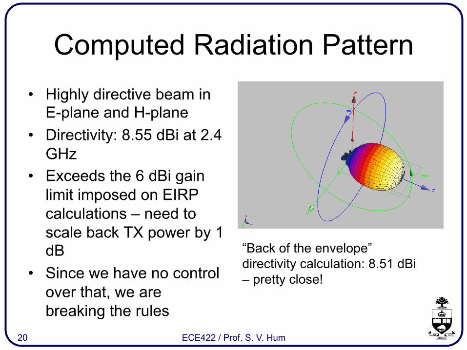
Computed Radiation Pattern • Highly directive beam in
E-plane and H-plane • Directivity: 8.55 dBi at 2.4
GHz • Exceeds the 6 dBi gain
limit imposed on EIRP calculations – need to scale back TX power by 1 dB
• Since we have no control over that, we are breaking the rules
20 ECE422 / Prof. S. V. Hum
“Back of the envelope” directivity calculation: 8.51 dBi – pretty close!

Modifying the Access Point • Starting point: Linksys
WUSB854G • Stock antenna: integrated λ/2 dipole
• What kind of range improvement does the cantenna provide?
• Need to connect antenna port on device to SMA connector on cantenna
21 ECE422 / Prof. S. V. Hum
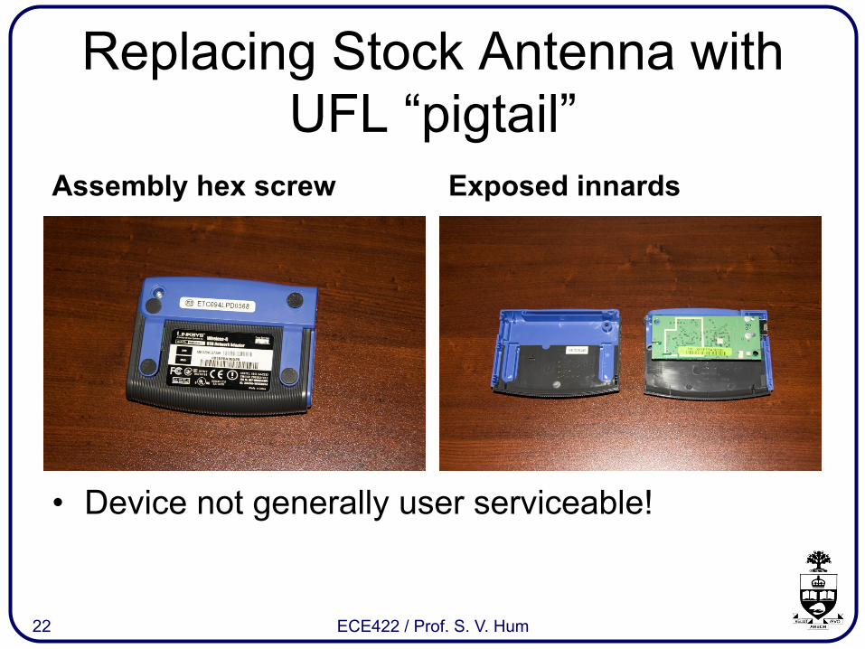
Replacing Stock Antenna with UFL “pigtail”
Assembly hex screw Exposed innards
22 ECE422 / Prof. S. V. Hum
• Device not generally user serviceable!

Replacing Stock Antenna with UFL “pigtail”
Front side w/antenna Replacement UFL pigtail
23 ECE422 / Prof. S. V. Hum

Observations • Significantly more access
points are visible with new antenna
• RSSI of existing stations increases by about 6 dB
• Theoretical improvement should yield a minimum of double the range as before
24 ECE422 / Prof. S. V. Hum

Conclusions and Extensions • Aperture antennas can be
easily fabricated and used to “improve WLAN link budgets” using household items
• Aperture / waveguide theory helps guide the design
• Many more access points can be picked up by the cantenna compared to a standard integrated laptop antenna
• Existing stations can be picked up over longer distances
• Extensions: larger antenna (e.g. “woktenna”)
25 ECE422 / Prof. S. V. Hum

Acknowledgement
• Krishna Kumar Kishor, for simulating the cantenna design in SEMCAD, and for testing the final antenna
26 ECE422 / Prof. S. V. Hum