case study: fish processing plant wastewater treatment
TRANSCRIPT
6860 Cortona Dr. • Goleta, CA 93117 • Phone (805) 685 9100 • Fax (805) 685 9105 www.cleanwatertech.com
Page 1
CASE STUDY: FISH PROCESSING PLANT WASTEWATER TREATMENT
1Miroslav Colic, Clean Water Technology, Inc. Wade Morse, Clean Water Technology, Inc. Jason Hicks, Clean water Technology, Inc.
Ariel Lechter, Clean Water Technology, Inc. Jan D. Miller, University of Utah
1Clean Water Technology, Inc. 6860 Cortona Dr., Building A
Goleta, CA 93117
ABSTRACT This presentation describes the full scale installation of a wastewater treatment system at the Ocean Gold Seafood (�OCS�) plant in Westport, Washington, USA. Local Government requires that fish processors remove total suspended solids (TSS), fats, oil and grease (FOGs) and colloidal materials almost completely in order to allow for efficient disinfection. The OCS plant had only a limited amount of space. Clean Water Technology, Inc. (�CWT�) and OCS teams designed the system with an underground equalization tank, 1/8 inch rotating drum screens, flocculation � flotation (�GEM System�) and chlorination � dechlorination. Hybrid centrifugal � dissolved air flocculation � flotation (the GEM System), is the key component of the wastewater treatment plant. The GEM System built to treat 500 GPM of wastewater required only an 8� � 16� area. The System has operated since 2004. TSS and FOGs are almost completely removed to less than 20 mg/l and 1 mg/l, respectively. This allowed for successful breakpoint chlorination � dechlorination and fecal coliform removal (99.995%). The produced sludge after overnight drainage contains over 15% of solids. Novel ultrahigh molecular weight polyacrylamide flocculants used in the process enabled TSS and FOG removal even at high salinity. The GEM System variable mixing energy inside hydrocylone heads and columns enabled activation of flocculant long polymeric chains without chain or floc breakage that occurs with classical impeller high energy mixing. KEYWORDS Fish processing wastewater treatment, flocculation � flotation, TSS, FOG and fecal coliforms removal
6860 Cortona Dr. • Goleta, CA 93117 • Phone (805) 685 9100 • Fax (805) 685 9105 www.cleanwatertech.com
Page 2
INTRODUCTION The seafood industry consists primarily of many small processing plants, with a number of larger plants located near industry and population centers. Numerous types of seafood are processed, often at the same plant. Saltwater fish (tuna, sardines, pacific whiting, swordfish), mollusks (oysters, clams, scallops), crustaceans (crabs and lobster) and others such as shrimp, octopus etc. are often processed concurrently or seasonally. As in most processing industries, seafood � processing operations produce wastewater containing a substantial amount of contaminants in soluble, colloidal and particulate forms. The degree of contamination depends on the process. It may be small (washing operations), mild (fish filleting), or heavy (boat storage tanks unloading, blood water from facilities storage tanks, �stick water� from fishmeal processing). Wastewater from seafood processing operations can be very high in dissolved and suspended organic materials. This results in high biological oxygen demand (BOD) and chemical oxygen demand (COD). Fats, oil and grease are also present in high amounts. Often suspended solids and nutrients such as nitrogen and phosphate can be high. Unpleasant odor and high temperature are also issues. Seafood processing wastewater was noted to sometimes contain a high concentration of sodium chloride from boat unloading, processing water and brine solutions. The major types of waste found in seafood processing wastewater are blood, offal products, viscera, fins, fish heads, shells, skins, and meat �fines�. The major process operations include product receiving, boat unloading, sorting and weighing, preparation (butchering, scaling, filleting, skinning, evisceration), inspection and trimming, product processing such as pickling brining etc, further processing (canning, bottling), packaging and dispatch. Organic materials in the wastewater are produced in the majority of these processes. However, most of it originates from the butchering process, which generally produces organic materials such as blood and gut materials. Wastewater from seafood processing industries generally can be divided into two categories: high volume � low strength wastes and low volume � high strength wastes. High volume � low strength wastes consist of the water used for unloading, fluming, transporting, and handling the fish plus the washdown water. The boat bilge water, fish preparation water and �stickwater� from fish meal processing are examples of low volume � high strength water. The degree of pollution of wastewater depends on several parameters. The type of operation involved and type and amount of seafood processed are the most important factors involved. Good manufacturing practices, including water savings and segregation of high strength wastes also influence the strength and volume of wastewater produced. Tuna canning plants commonly produce light, easy to treat wastewater, with low BODs and CODs (700 and 1,600 mg/l average was reported), low TSS (up to 500 mg/l) and moderate FOGs (up to 500 mg/l). Fishmeal plants were reported to produce some of the most contaminated and challenging to treat wastewater with BODs and CODs as high as 30,000 and 50,000 mg/l, TSS 30,000 mg/l and FO�s over 10,000 mg/l. All herring processing also produces heavy load wastewater. Salmon, cod, mahi-mahi, and pacific whiting processing produce moderately contaminated wastewaters with BODs

6860 Cortona Dr. • Goleta, CA 93117 • Phone (805) 685 9100 • Fax (805) 685 9105 www.cleanwatertech.com
Page 3
and CODs up to 6,000 and 15,000 mg/l, TSS up to 12,000 mg/l and FOGs up to 2,000 mg/l. Crab and shrimp processing also produce moderately contaminated wastewater. Fats, oil and grease are among the most objectionable components from the seafood processing wastewater. The presence of FOG in an effluent is mainly due to processing operations such as canning. Fish oil, unless removed in a fishmeal plant, often ends up in the processing wastewater. The FOG should be removed from wastewater for numerous reasons: it usually floats on top of water�s surface and affects the oxygen transfer to the water; it is objectionable from an aesthetic point of view, and its decomposition generates unpleasant odors. FOGs also cling to tanks as well as pumps, ducts and pipes reducing their capacity in the long term. The FOGs of a seafood processing wastewater varies from 10 to 20,000 mg/l, depending on the seafood being processed and the operation being carried out. Suspended solids (TSS) present similar problems. Heavy solids also sediment and over time can clog pumps, pipes, tanks or accumulate at waterways floors. Solids and FOGs should be removed as soon as possible in the wastewater treatment process with as low shear � mixing energy as possible. Time and shear energy often dissolve solid and colloidal components. Dissolved organic materials are much more expensive to remove. SEAFOOD PROCESSING WASTEWATER TREATMENT First step in wastewater treatment and system design is sampling and sample analysis. The seafood processing wastewater often varies considerably by hour, day, week and season. Obtaining a representative sample to design a treatment system can be a real problem. Often only a single point sample is available in the early stages of the design process. Second step, if possible, should be the collection of 24 hours of effluents on an hourly basis. This may identify peak loads of contaminants, peak flows and duration of peak loads and flows. The best location to take a sample is prior to the discharge to the receiving water body. In addition to the analysis of contaminants loads such as TSS, FOG, COD, BOD, nutrients, it is always a good idea to perform jar tests to determine best dosage and type of treatment chemicals, such as pH adjustment (acid and base), coagulants, flocculants and defoamers if needed. Such data can be a tremendous help when designing the primary treatment system. If possible such samples should also be treated with laboratory sieves/screens to determine the best pore size and type of screen to install. A stepwise approach to wastewater treatment commonly yields the best results in the most economic way. The primary treatment deals with the removal of suspended solids, colloidal materials and large screenable and settable solids. As already mentioned, in the treatment of seafood wastewater solids and colloids, they should be removed fast and with low shear technologies in order to avoid dissolution. For seafood processing wastewater, the primary treatment processes are flow equalization, screening, sedimentation, the pH adjustment - flocculation � flotation, and microfiltration. Equalization Equalization Tanks (EQ). Proper equalization of an industrial effluent can provide a more constant and homogeneous flow to the flotation unit. This can improve the effectiveness of the

6860 Cortona Dr. • Goleta, CA 93117 • Phone (805) 685 9100 • Fax (805) 685 9105 www.cleanwatertech.com
Page 4
chemical treatment program used for coagulation and flocculation prior to flotation. In addition, equalization reduces hydraulic surging, which can be detrimental to the system performance. In some cases, EQ tanks can be sized to allow operation of the flotation units during specific time periods (e.g., a single plant shift), thus reducing operator labor costs. Equalization also allows for installations of screens with smaller capacities (average as opposed to peak flow). Screening The removal of relatively large solids (0.7 mm or larger) can be achieved by screening. Screening is one of the cheapest and simplest wastewater treatment steps used in food processing plants. Flow � through static screens with openings around 1mm are among the most popular configurations. Sometimes a self-cleaning mechanism such as scrapping or jet cleaning (water or gas jets) is included. Tangential screens are static screens less prone to fouling due to their flow characteristics. They are designed so that wastewater flow avoids clogging. Such screens are mostly cleaned manually with water jets or brushes/scrapers. Rotary drum screens are mechanically more complex. They consist of a drum that rotates along its axis, and the influent enters through opening at one end. Screened wastewater flows outside the drum and the retained solids are washed out from the screen into a collector in the upper part of the drum by a spray of water. Such spray is also used for self � cleaning. If needed, spraying can be done with cleaning solutions. Depending on how the screen material is manufactured, screens can be described as perforated sheet, mesh or wedge-wire. Screens with perforated sheets are less prone to fouling with hair or small fish bones. Such screens are therefore more often used in seafood and meat processing plants. Screens used in seafood processing wastewater treatment often can remove between 30% and 80% of solids. This can substantially reduce load to subsequent primary treatment steps such as flotation. Savings in amount and cost of treatment chemicals such as coagulants and flocculants can also be achieved. Coagulation and Flocculation Coagulation, flocculation and flotation are among the most effective approaches to remove fats oils and grease, suspended solids and colloidal materials (even some proteins and macromolecules) from any food processing wastewater. Solids, colloids and macromolecules present in seafood processing wastewater are generally charged. Charge stabilization often produces very stable colloidal suspensions. Solids and colloids that are charge stabilized repel each other and produce systems that have a tendency to �swim� within the wastewater bulk, rather than sediment or float. Surface charge has to be neutralized in order to get particles close together so that other attractive forces such as hydrophobic or van der Waals forces result in formation of larger aggregates that either sediment or attach to bubbles and float. Most colloids, macromolecules and solids in seafood processing wastewater are of organic nature. Ionization of carboxyl and amino groups from fatty acids or proteins produces some charge. Oil and grease particles are often emulsified and charge is present in the surfactants used as emulsifying agents. Many neutral colloids will preferentially adsorb hydroxyl ions and become negatively charged. Most colloids present in any food processing wastewater are negatively charged, probably due to preferential adsorption of hydroxyl ions and widespread surface availability of carboxyl groups. The surface charge/dissociation of such groups is pH dependent. It is possible to find a pH at

6860 Cortona Dr. • Goleta, CA 93117 • Phone (805) 685 9100 • Fax (805) 685 9105 www.cleanwatertech.com
Page 5
which total surface charge is zero (point of zero charge). At such pH colloids are quite unstable. However, coagulants and flocculants are designed so as to promote even faster, more efficient destabilization of colloids with growth of large, stable aggregates. The pH, therefore, should be adjusted close to the point of zero charge, in order to save on dosage of coagulants and flocculants needed to neutralize the surface charge. If surface charge is fully neutralized, the performance of flocculants is low. Once the pH is adjusted, coagulation and flocculation process follow. Coagulation is addition of oppositely charged ions or molecules in order to neutralize surface charge and destabilize colloidal suspensions. Inorganic coagulants such as sulfate or chloride salts of trivalent iron (Fe[III]) or aluminum (Al[III]) have been quite popular in food processing wastewater treatment. However, such salts hydrolyze as part of coagulation process and produce oxohydroxyde sludge that is bulky and difficult to dewater. Prehydrolyzed �inorganic polymeric aluminum reagents such as polyaluminum chloride (PAC) or aluminum chlorohydrate (ACH) are more efficient in charge neutralization. Such salts also produce less bulky sludge. Cationic polyelectrolytes (organic low molecular weight polymers) such as quaternary polyamines produce less sludge that is easier to dewater. Such reagents are also much more efficient in charge neutralization. Therefore, the dosages needed to neutralize surface charge with polyelectrolytes are often more than order of magnitude lower compared to dosages of aluminum or iron salts. However, ferric salts have to be used if blood clarification is to be achieved. Precipitation of phosphate or sulfide ions also can be achieved only with inorganic ions. Finally some proteins can be removed with proper pH adjustment and use of inorganic coagulants. Flocculation is a process of formation of large stable flocs that either sediment or float. Flocculants are reagents that achieve flocculation. Flocculants are large polymeric molecules that bind together smaller flocs produced by coagulation. Synthetic high molecular weight polyacrylamides are the most commonly used flocculants. Cationic polyacrylamides can neutralize residual negative surface charge and also bind smaller flocs together. Flocs may also be overcharged with coagulants and cationic flocculants, with subsequent use of anionic polyacrylamide. Such approach, termed dual flocculants approach, will be described in detail later in this manuscript (also see Figure 1). Several steps are involved in the coagulation and flocculation processes. First, coagulants are added to the wastewater with the precise dosing pumps. Then coagulants are mixed with the particles in the high energy mixing process in order to uniformly distribute adsorbed coagulant molecules or ions. Upon initial charge neutralization, flocculants are added. Even more precise dosing is needed in order to avoid under or overcharging of particles. Flocculants are mixed with less energy in order to avoid breakup of formed flocs or even polymer molecules, which are large delicate chains. On the other hand, enough mixing intensity is needed to achieve uniform distribution of polymer and adsorption on all particles, rather than over absorption on nearby particles only. Mixing is also needed to activate polymeric flocculants. Such giant molecules are coiled into the tight coils. Linearization is needed to achieve polymer configuration that can bind numerous smaller flocs together (see Figure 2).

6860 Cortona Dr. • Goleta, CA 93117 • Phone (805) 685 9100 • Fax (805) 685 9105 www.cleanwatertech.com
Page 6
Figure 1. Schematic presentation of the dual polymeric flocculant flocculation.
+
+
+ +
+
+
+ +
-
-
-
-
+
+
+
+
+
+

6860 Cortona Dr. • Goleta, CA 93117 • Phone (805) 685 9100 • Fax (805) 685 9105 www.cleanwatertech.com
Page 7
Figure 2. Mixing to activate � uncoil coiled high molecular weight polyacrylamide flocculant molecules. Synthetic polyacrylamide flocculants can be manufactured in four different ways, as granular, emulsion, brine (water solution) or direct dispersion (concentrated emulsion) solutions. Prior to use, flocculants have to be hydrated with water molecules and activated (partial uncoiling). This laborious, time-consuming process can be automated. Granular high molecular weight polyacrylamides are the most efficient flocculants. Since they are 85-95% pure, less dosage is needed compared to other solution reagents such as emulsions or brines. However, the dissolution and activation process is more time and labor intensive. Emulsions can be diluted and activated with the automated makedown units. However, such units are expensive and often do not yield constant polymer concentration. Phase separation can occur during storage. Emulsion flocculants are also less efficient than granular reagents. Finally, most emulsion flocculants are 20 � 40 percent active polymer only. This means that you will need 2-4 times more emulsion flocculant as compared to granular. Brines use special stabilization additives to dissolve concentrated polymeric flocculants in water solutions. Makedown units for such polymers are much cheaper, and no phase separation occurs. However, they cannot be
+
+ +
+
+
+
+
Coiled Flocculant
Partially UncoiledFlocculant
Mixing

6860 Cortona Dr. • Goleta, CA 93117 • Phone (805) 685 9100 • Fax (805) 685 9105 www.cleanwatertech.com
Page 8
manufactured at more than 25% of active ingredients, and are also very expensive. Direct dispersions are emulsions that are concentrated by removal of oil and water. Direct dispersion may contain between 50 -80% of active flocculant polymer. However, direct dispersions with more than 70% of actives are currently not on the market. Such flocculants can be directly added into the flotation or sedimentation polymer mixing units without a need for activation. This could significantly reduce time and labor costs in the future. At the moment, granular and emulsion flocculants are still the most often used ones. Proper dosage of coagulants and flocculants is very important. Simple jar tests to determine the optimum pH, coagulant and flocculant dosage should be performed every 2-3 hours. If large equalization tanks are installed, one can adjust dosages only once a day. However this rarely happens in practice. Another option is to install automatic dosage control systems. Such systems follow strength or charge of incoming influent, effluent (or both) and adjust coagulants and flocculants dosages accordingly. Turbidity or particle charge can be used as criteria for wastewater characterization. Computer software exists to analyze such data and control the dosage pumps. Automated dosage systems are very expensive and few plants currently use them. Flotation Flotation is one of the most effective removal systems for suspensions that contain fats, oil and grease mixed with low density organic suspended solids. Flotation is a process in which one or more specific particulate (particular) constituents of a slurry or suspension of finely dispersed particles or droplets become attached to gas bubbles so that they can be separated from water and/or other constituents. Gas/particle aggregates float to the top of the flotation vessel where they are separated from water and other non - floatable constituents. Flotation processes in water and wastewater treatment are designed to remove all suspended particles, colloids, emulsions, and even some ions or soluble organics that can be precipitated or adsorbed on suspended solids. In this case, the process is optimized by the maximum recovery of cleaned water with the lowest concentration of contaminants. It is also often desired that the recovered sludge contain a high percentage of solids. Such solids can sometimes be recycled and reused. The design features and operating conditions of flotation equipment used for this purpose must be modified accordingly. It is evident that the processes causing water loss to the froth phase or migration of solids to the water phase must be minimized and appropriate conditions established for complete particle recovery. A recent review summarizes new developments in flotation as a wastewater treatment technique (Rubio et al., 2002). One of the key steps in the flotation method is the introduction of air bubbles into water. In early flotation machines, coarse bubbles (2 to 5 mm) were introduced into the contaminated water by blowing air through canvas or other porous material. In some impeller-based machines, air could be introduced from the atmosphere without compressors or blowers. This type of flotation, in which impeller action is used to provide bubbles, is known as induced-air flotation (IAF) and also produces fairly coarse bubbles. Such flotation methods are not suitable for wastewater treatment and oil extraction. Jameson (Clayton et al., 1991) developed an improved version of induced-air flotation, which was more successful in the removal of fats, oil, and grease from the

6860 Cortona Dr. • Goleta, CA 93117 • Phone (805) 685 9100 • Fax (805) 685 9105 www.cleanwatertech.com
Page 9
wastewater. Another flotation method, called dissolved-air flotation (DAF), is much more common in the treatment of oily wastewater (Bratby and Marais, 1977; Kiuri, 2001). In DAF, a stream of wastewater is saturated with air at elevated pressures up to 5 atm (40-70 psig). Bubbles are formed by a reduction in pressure as the pre-saturated water is forced to flow through needle valves or specific orifices. Small bubbles are formed, and continuously flowing particles are brought into contact with bubbles. There is a price to pay for having such small bubbles (up to 20 microns): Such bubbles rise very slowly to the surface of the tank. This is the main driver of the large dimensions for DAF tanks. Final solubility of gas in water, even at high pressures, also results in fairly low air-to-water ratios. Air-to-water ratios of 0.15:1 by volume are common in DAF systems, and it is very difficult to achieve higher ratios. Therefore, classical DAF systems are not efficient in treating wastewater with more than 1% of suspended solids. DAF units have been somewhat successful in the treatment of the seafood processing wastewater (Tay et al., 2006). When used without coagulants and flocculants, DAF units can remove up to 50% of suspended solids and 80% of FOGs. Addition of coagulants and flocculants increased separation efficiencies to between 80 and 95%. Removal of COD/BOD depends on the amount of dissolved materials and separation efficiencies can vary between 15 and 65%. DAF units used in seafood processing wastewater treatment are usually operated around pH 5 to minimize protein solubility. Ferric sulfate is used as coagulant to help with blood clarification. Few ppm�s of anionic flocculants are added to increase the size of flocs. Floc tubes or impeller-based mixers are used for coagulant and flocculant mixing. NEW DEVELOMENTS IN FLOTATION SYSTEMS Centrifugal Flotation Systems As mentioned earlier, DAF systems have some serious limitations. While small bubbles used in such systems yield better contaminant removal efficiencies than IAF or other flotation techniques, there is a price to pay for small bubbles: rise time of particles attached to bubbles is minutes, which results in long water residence time inside flotation tanks and a large footprint � tank size. The solubility of air in water and a necessity of recycling instead of full flow treatment limit the number of bubbles that can be produced in such systems. Until recently, these matters limited the use of DAF systems for applications in which high strength industrial wastewater was treated. Coagulation and flocculation are performed ahead of bubble nucleation. Therefore, bubble attachment is the only mechanism of particle removal. If gases could nucleate inside simultaneously nucleated flocs, more efficient processes can be developed. To address these and other limitations of DAF systems, other flotation techniques have been developed and applied in industrial wastewater pretreatment. Air Sparged Hydrocyclone Flotation (ASH) One of the recent developments in flotation technology circumvented some of these problems. In particular, the air-sparged hydrocyclone (ASH) couples a porous cylindrical membrane with design features of a hydrocyclone (Miller, 1981). Gas is introduced through the porous membrane while wastewater is pumped through the hydrocyclone. Such a device is not

6860 Cortona Dr. • Goleta, CA 93117 • Phone (805) 685 9100 • Fax (805) 685 9105 www.cleanwatertech.com
Page 10
dependent on the gas solubility and can introduce air-to-water ratios as high as 100:1. Because the bubbles are sheared off the wall of the porous membrane due to the high velocity and centrifugal forces inside the hydrocyclone, they are broken up into very small sizes comparable to those observed in the DAF. Thus, even though the ASH is essentially a mechanically sparged device similar to the IAF or early flotation devices, it does not suffer from similar problems. The ASH is one of the first centrifugal flotation techniques that was developed and applied in the treatment of wastewater. The ASH and other centrifugal flotation systems will be described below. Because the ASH is essentially a modified hydrocyclone device, it has similar restrictions. Removed particulates in such devices are forced through an overflow device known as the vortex finder. In the ASH, the creation of an overflow results in a separate stream of contaminated water with a low concentration of solids. This deficiency results in sludge with low particulate concentrations and a larger volume of waste. Below, we discuss modifications to the ASH device. Bubble-accelerated flotation (BAF) evolved from ASH technology to address operational limitations resulting from the traditional stream-splitting characteristics of hydrocyclones. BAF no longer incorporates a cleaned-water underflow restriction that forces the froth and contaminants to be ejected through a vortex finder. Removing the underflow restriction in the BAF improves the consistency and ease of operation. The point at which the stream exits the BAF hydrocyclone, the bubble/particle aggregates have already formed, and coagulation and flocculation are complete before the froth particles are ejected with the cleaned water through the underflow. The requirement to separate this froth in the receiving tank from the treated water results in the new system described below.
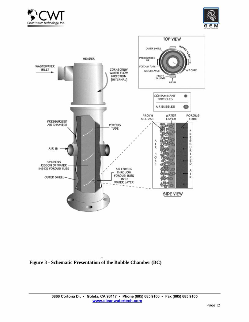
Bubble Accelerated Flotation (BAF) Description and Principles of Operation The BAF system consists of a bubble chamber and a BAF tank. The bubble chamber can be operated with sparged air, induced air, vacuum, electro-flotation and even dissolved air. We will describe the air-sparged bubble chamber and BAF system. Such systems are commercially installed and successfully operated in over twenty locations within the U.S. See Morse et al. (2000 and 2001), Owen et al. (1999), and Colic et al. (2001) for detailed descriptions of this system. Figure 3 contains an illustration of the air-sparged bubble chamber. Wastewater is introduced through a liquid/liquid hydrocyclone head (tangential injection) at the top of the unit. The tangential inlet creates a swirl flow and causes centrifugal acceleration as the water is forced into a swirl layer against the inner wall of an inert porous tube. A gas plenum, which encloses the porous tube, is pressurized commonly with low-pressure air from a blower. The air pressure must slightly exceed the water pressure due to the centrifugal acceleration and the resistance of the tube itself. Gas forced through the porous tube generates bubbles on the inside surface due to high shear. These bubbles are extremely buoyant in the centrifugal field because of the effective radial pressure gradient in the swirl layer generated by the hydrocyclone action. The bubbles accelerate toward the inner surface of the swirl layer. In addition to creating the radial acceleration of the bubbles, the centrifugal field also aids in the classification of particles with densities different from that of water. The acceleration across the swirl layer usually ranges from 25 to 1,000 Gs during routine operation. Even though the residence time of the liquid stream in the bubble chamber is only a fraction of a second, due to their rapid acceleration, the bubbles
6860 Cortona Dr. • Goleta, CA 93117 • Phone (805) 685 9100 • Fax (805) 685 9105 www.cleanwatertech.com
Page 11
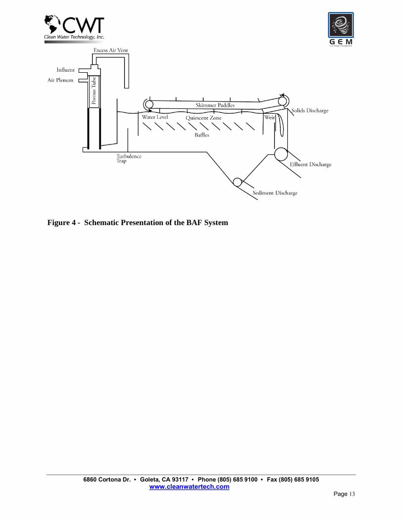
traverse the short distance across the swirl layer (typically 1 cm for a 15-cm diameter unit) in milliseconds. During this time, the bubbles collide with particles moving toward the porous tube and form bubble/particle aggregates. Another advantage of the sparging gas is that it cleans and protects the porous tube from scaling and fouling. Given the small bubble size, large bubble flux, and the kinetic paths of the bubbles through the swirl layer, gas transfer rates are very high. This results in the ability to remove volatile organic species or to aerate the water if desired. The flotation process is completed outside the bubble chamber in the BAF tank. In a DAF system, the tank is designed to allow sufficient residence time for the bubbles and particles to collide and for the resulting aggregates to rise to the surface. This results in low hydraulic flow rates in order to permit bubble/particle aggregates to form and to float to the surface without being swept out of the system. In DAF systems, the low hydraulic flow rate is accomplished by increasing the cross-sectional area of the flow and consequently enlarging the tanks. Consequently, for the DAF there is a trade-off between footprint and residence time. The design needs for BAF separation tanks are completely different. The bubble chamber has already created bubble/particle/polymer aggregates before they enter the tank. The tank is simply used as a separator and not to achieve bubble/particle contact. Unlike other flotation tanks, the effluent from the bubble chamber can enter the tank above the water level, resulting in a shorter distance for the froth to reach the surface. This feature, combined with the fact that the aggregates are already formed, permits much higher hydraulic flow rates through the flotation tank. Figure 4 illustrates the BAF tank with the bubble chamber attached.
6860 Cortona Dr. • Goleta, CA 93117 • Phone (805) 685 9100 • Fax (805) 685 9105 www.cleanwatertech.com
Page 12
Figure 3 - Schematic Presentation of the Bubble Chamber (BC)
6860 Cortona Dr. • Goleta, CA 93117 • Phone (805) 685 9100 • Fax (805) 685 9105 www.cleanwatertech.com
Page 13
Figure 4 - Schematic Presentation of the BAF System
6860 Cortona Dr. • Goleta, CA 93117 • Phone (805) 685 9100 • Fax (805) 685 9105 www.cleanwatertech.com
Page 14
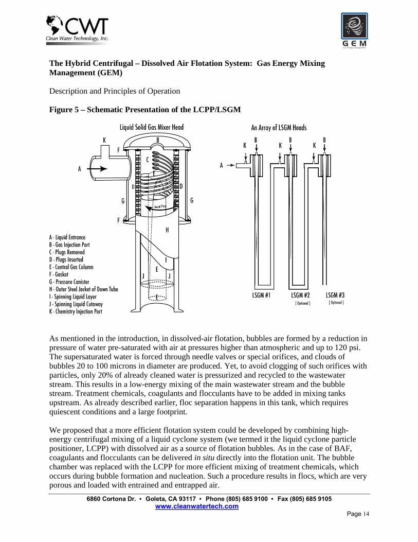
The Hybrid Centrifugal – Dissolved Air Flotation System: Gas Energy Mixing Management (GEM) Description and Principles of Operation Figure 5 – Schematic Presentation of the LCPP/LSGM
As mentioned in the introduction, in dissolved-air flotation, bubbles are formed by a reduction in pressure of water pre-saturated with air at pressures higher than atmospheric and up to 120 psi. The supersaturated water is forced through needle valves or special orifices, and clouds of bubbles 20 to 100 microns in diameter are produced. Yet, to avoid clogging of such orifices with particles, only 20% of already cleaned water is pressurized and recycled to the wastewater stream. This results in a low-energy mixing of the main wastewater stream and the bubble stream. Treatment chemicals, coagulants and flocculants have to be added in mixing tanks upstream. As already described earlier, floc separation happens in this tank, which requires quiescent conditions and a large footprint. We proposed that a more efficient flotation system could be developed by combining high-energy centrifugal mixing of a liquid cyclone system (we termed it the liquid cyclone particle positioner, LCPP) with dissolved air as a source of flotation bubbles. As in the case of BAF, coagulants and flocculants can be delivered in situ directly into the flotation unit. The bubble chamber was replaced with the LCPP for more efficient mixing of treatment chemicals, which occurs during bubble formation and nucleation. Such a procedure results in flocs, which are very porous and loaded with entrained and entrapped air.

6860 Cortona Dr. • Goleta, CA 93117 • Phone (805) 685 9100 • Fax (805) 685 9105 www.cleanwatertech.com
Page 15
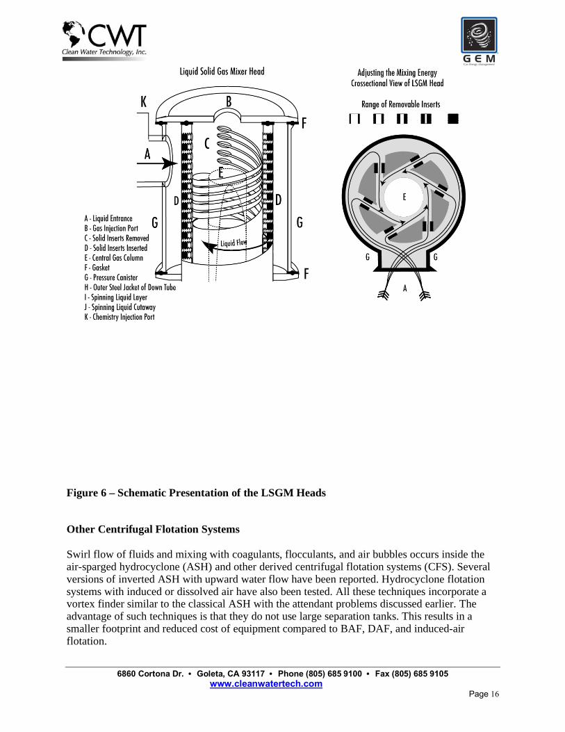
As shown in Figure 5 the LCPP also acts as a liquid-solid-gas mixer (LSGM). Replacing the classical hydrocyclone head with the LCPP provides extremely energetic mixing by sequentially transporting liquid and entrained particles and gas bubbles throughout a centrifugally rotating liquid layer. Microturbulence in such vortices results in all particles and bubbles down to colloidal and molecular size acting as little mixers. Axial and radial forces inside the LCPP help mix coagulants and flocculants with the particles. Uncoiling of polymer and better mixing of ultrahigh-molecular-weight polymers is achieved in the LCPP. Such efficient mixing is important for proper flocculation of suspended particles. Further modification of LCPP heads, as opposed to hydrocyclone heads, introduced multiple holes with plugs inside the LSGM heads, as shown in Figure 6. By changing the number of plugs, we can modify the mixing energy and head pressure from very low to very high. In this way, we can mix low-molecular-weight coagulant at relatively high energy and high-molecular-weight flocculants at relatively medium and low mixing energy to promote final large floc formation. Figure 7 presents a schematic of the GEM flotation system. It should be noted that for the sake of clarity only one LSGM head is presented. If more treatment chemicals are added, the LSGM head can be used to properly mix every additional chemical at its proper mixing energy (one mixing head per addition). Water and gas are introduced into the LSGM on top and pumped through the LCPP chamber. After rapid mixing (seconds), pressure is released with the cavitation plate. Nucleating bubbles and flocs are well mixed. As mentioned before, this results in the formation of large flocs full of entrained and entrapped air. Such flocs are already separated from water inside the LCPP nucleation chamber. As flocs enter the tank, they rise quickly to the top where they are skimmed and sent to solids dewatering devices. As compared to the ASH and BAF, the GEM system uses less energy, since there is no need for air blowers for air sparging. This also results in less noise. Controlled mixing energy produces stable flocs with much less carryover and higher solids loading. The footprint for this system is still only 10 to 20% of the classical DAF or clarifier devices. A blanket of small bubbles inside the tank acts as a "gas filter," filtering out clean water while preventing the transport of small pinpoint flocs into the clean water stream. Also, when wastewater with surfactants is treated no foaming occurs inside the GEM system. Finally, it is possible to install sensors close to the nucleation chamber and observe any disturbance in flocculation performance almost instantaneously. This can be used to install turbidity-driven, chemical-additive dosage-control systems. Such systems can save significant amounts of money and produce a better quality of outgoing wastewater effluent. A detailed description of the GEM system can be found in Morse et al. (2004a, 2004b).
6860 Cortona Dr. • Goleta, CA 93117 • Phone (805) 685 9100 • Fax (805) 685 9105 www.cleanwatertech.com
Page 16
Figure 6 – Schematic Presentation of the LSGM Heads
Other Centrifugal Flotation Systems
Swirl flow of fluids and mixing with coagulants, flocculants, and air bubbles occurs inside the air-sparged hydrocyclone (ASH) and other derived centrifugal flotation systems (CFS). Several versions of inverted ASH with upward water flow have been reported. Hydrocyclone flotation systems with induced or dissolved air have also been tested. All these techniques incorporate a vortex finder similar to the classical ASH with the attendant problems discussed earlier. The advantage of such techniques is that they do not use large separation tanks. This results in a smaller footprint and reduced cost of equipment compared to BAF, DAF, and induced-air flotation.

6860 Cortona Dr. • Goleta, CA 93117 • Phone (805) 685 9100 • Fax (805) 685 9105 www.cleanwatertech.com
Page 17
Figure 7 – Schematic Presentation of the Hybrid Centrifugal – Dissolved Air Flotation
System
Modified versions of the jet (Jameson cell) flotation system have also been developed and applied. In a recent advancement of the Jameson cell technology, a new “low shear” method is used to mix the air, untreated wastewater, and flocculants. As in the previously described induced-air BAF system, untreated wastewater and flocculants are gently introduced into the top of the cylinder used for centrifugal mixing (termed the downcomer for Jameson cell systems). A portion of the clean effluent is recycled back into the top of the downcomer. The recycle effluent passes through an orifice, accelerating the liquid to produce a simple liquid jet. The kinetic energy of the jet results in air being entrained into the downcomer in much the same way as air might be entrained into a bucket of water using a hose. Air is dragged down into the liquid and broken up into small bubbles by the turbulence in the top of the downcomer. The Jameson cell
6860 Cortona Dr. • Goleta, CA 93117 • Phone (805) 685 9100 • Fax (805) 685 9105 www.cleanwatertech.com
Page 18
thereby utilizes the energy of the fluid to induce air into the cell, rather than requiring an external compressor or blower. As in the case of the BAF system, the presence of air bubbles at the time of flocculation is extremely beneficial, as it results in the bubbles being entrapped with the actual floc structure. The incorporation of bubbles in the floc structure provides buoyancy and allows particles to be floated independent of their surface characteristics. The downward velocity of the bubble/liquid mixture in the downcomer is designed such that all bubbles have to descend and emerge into a reservoir (or cell) at the bottom of the downcomer. The reservoir acts as a disengagement zone, allowing the aerated floc structures to float to the surface to form a sludge layer. As in the case of BAF and GEM, separation already happens inside the centrifugal force column (in this case downcomer). The sludge overflows the reservoir into a launder, whilst the cleaned effluent passes to the next stage in the process. Other modifications of jet flotation include the DAF jet (dissolved-air mode) and addition of one more cylinder around the downcomer to lead separated flocs towards the top of the separation tank (Feris et al., 2004). While these modifications increase the cost and result in a more complicated system, they also increase the separation efficiency. Another turbulent in situ centrifugal flotation system, termed flocculation flotation (FF), was recently developed (daRosa and Rubio, 2005). As in the case of GEM, BAF, and the modified jet-flotation cell, polymer and air are added at the same time inside a centrifugal mixing system. Dissolved air is used for smaller bubbles. As in the case of BAF and the GEM system, large flocs entrained with air develop when high-molecular-weight flocculants are used. Multiple cylinders around the downcomer are used, similar to the modified jet-flotation cell. The air excess leaves through the centrifugal cylinders at the top, and the flocs float very fast within seconds after leaving the downcomer cylinder. A novel flocculation and helical mixing system has also been developed by the same group (Carissimi and Rubio, 2005). Other Flotation techniques While it is impossible within the given space to review all recent developments in flotation techniques we will mention few other popular systems. Cavitation air flotation (CAF) utilizes an aerator (rotating disc), which draws ambient air down a shaft and injects “micro-bubbles” directly into the wastewater (as reported in Rubio et al., 2002). However, there is no knowledge of any fundamental work with this flotation technique. CAF is not as efficient as DAF or centrifugal flotation systems, but is very economically feasible and simple to operate. Gas aphrons and suspended air flotation (SAF) is based on the use of colloidal gas aphrons, micro-foams or simply micro-gas – suspended air dispersions (as reported in Rubio et., 2002). They are dispersions of air in liquids formed with the use of a venturi generator, which introduces a gas to a circulating surfactant solution in a region of high velocity and low pressure. This produces very small stable bubbles, which range in size from 10 to 50 microns and provide a large amount of surface area. The disadvantage of this technique is that it adds surfactants into wastewater. Nozzle flotation (NF) process uses a gas aspiration nozzle (an educator or exhauster) to draw air into recycled water, which in turn is discharged into a flotation vessel (similar to the dispersed-

6860 Cortona Dr. • Goleta, CA 93117 • Phone (805) 685 9100 • Fax (805) 685 9105 www.cleanwatertech.com
Page 19
air conventional IAF machines) to develop a two-phase mixture of air and water (as described in Rubio et al., 2002). Low initial cost, energy use and maintenance are characteristics of this system. Applications reported have been exclusively in the treatment of oily wastewater from petrochemical industries. LABORATORY AND PILOT STUDIES OF THE SEAFOOD PROCESSING WASTEWATER Laboratory Studies Representative samples from 22 different seafood-processing plants have been collected for the laboratory jar tests. The purpose of these tests were to evaluate various coagulants, flocculants, pH treatment and capacity of flocculation � flotation technique to reduce TSS, turbidity, FOG, COD and BOD. The most efficient and economically feasible chemistries were then tested in the pilot studies with the BAF and GEM Systems prior to full -scale installations. Wastewater samples were coagulated and flocculated at numerous pHs ranging from 3 to 11. For most samples, best flocculation can be achieved at pH between 5 and 6. Removal of fine emulsions and proteins is also most efficient in this pH range. Some wastewater samples had a very small amount of TSS and colloidal materials. For such samples, the pH was adjusted between 7 and 9. Similar approach was used for samples with colloidal materials that are almost neutral. Increasing pH above 8 results in higher surface charge and stronger adsorption of flocculants. At pHs below 5, performance of flocculants was found to be sub optimal with smaller, weaker flocs and more carryover in laboratory flotation tests. At pHs above 9, consumption of coagulants and flocculants was very high. Numerous inorganic, organic and blend coagulants were tested with seafood processing wastewater. Ferric (FeIII) and aluminum(III) sulfate require the highest dosages and produce sludge with the lowest % solids that is most difficult to dewater and dry. As wastewater becomes loaded with TSS and FOGs, the necessary dosages to achieve coagulation can be as high as 6,000 mg/l. These two coagulants also interfere with the performance of flocculants, producing �pinpoint� floc with very small particles and high amount of carryover (often over 200 mg/l) in laboratory flotation tests. However, if water is rich in blood proteins, small amount of ferric coagulant (10-60 ppm) is needed to clarify wastewater and reduce foaming problems. Prepolymerized inorganic coagulants suffer from similar deficiency, namely large dosages needed, carryover after flotation produced, and sludge with low % solids produced. Needless to say, dosages are lower than that of monomeric ferric or aluminum ions based coagulants. The most popular reagents from this group are polyaluminum chlorides, (PAC) with various basisity and aluminum chlorohydrate (ACH). Also, inorganic coagulants produce sludge with tendency to sediment, rather than to float. Organic polyelectrolyte coagulants are the most advanced new generation of coagulant reagents. Usually, those are small cationic polymers with 100% backbone charge. Polyethyeleneimines were the first reagents used for such purpose. Modern quaternary polyamines, epiamine, and polydyallyldymethyl chlorides (polyDADMAC�s) are most often used in wastewater treatment
6860 Cortona Dr. • Goleta, CA 93117 • Phone (805) 685 9100 • Fax (805) 685 9105 www.cleanwatertech.com
Page 20
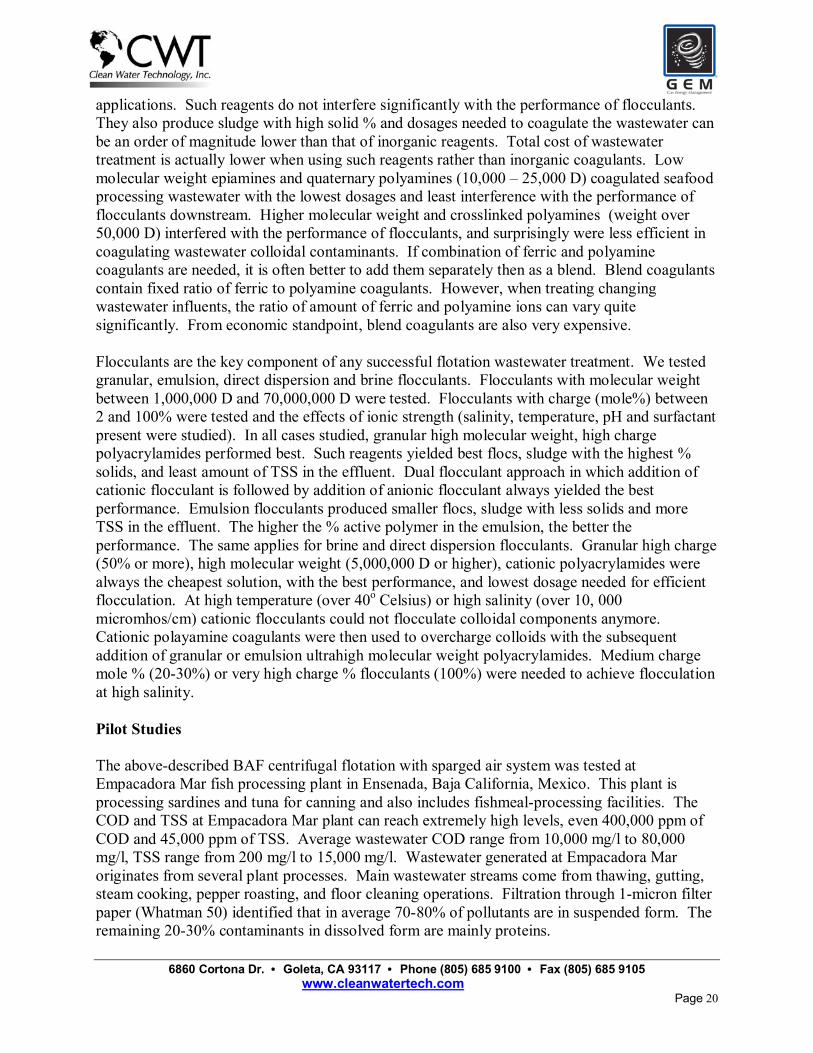
applications. Such reagents do not interfere significantly with the performance of flocculants. They also produce sludge with high solid % and dosages needed to coagulate the wastewater can be an order of magnitude lower than that of inorganic reagents. Total cost of wastewater treatment is actually lower when using such reagents rather than inorganic coagulants. Low molecular weight epiamines and quaternary polyamines (10,000 � 25,000 D) coagulated seafood processing wastewater with the lowest dosages and least interference with the performance of flocculants downstream. Higher molecular weight and crosslinked polyamines (weight over 50,000 D) interfered with the performance of flocculants, and surprisingly were less efficient in coagulating wastewater colloidal contaminants. If combination of ferric and polyamine coagulants are needed, it is often better to add them separately then as a blend. Blend coagulants contain fixed ratio of ferric to polyamine coagulants. However, when treating changing wastewater influents, the ratio of amount of ferric and polyamine ions can vary quite significantly. From economic standpoint, blend coagulants are also very expensive. Flocculants are the key component of any successful flotation wastewater treatment. We tested granular, emulsion, direct dispersion and brine flocculants. Flocculants with molecular weight between 1,000,000 D and 70,000,000 D were tested. Flocculants with charge (mole%) between 2 and 100% were tested and the effects of ionic strength (salinity, temperature, pH and surfactant present were studied). In all cases studied, granular high molecular weight, high charge polyacrylamides performed best. Such reagents yielded best flocs, sludge with the highest % solids, and least amount of TSS in the effluent. Dual flocculant approach in which addition of cationic flocculant is followed by addition of anionic flocculant always yielded the best performance. Emulsion flocculants produced smaller flocs, sludge with less solids and more TSS in the effluent. The higher the % active polymer in the emulsion, the better the performance. The same applies for brine and direct dispersion flocculants. Granular high charge (50% or more), high molecular weight (5,000,000 D or higher), cationic polyacrylamides were always the cheapest solution, with the best performance, and lowest dosage needed for efficient flocculation. At high temperature (over 40o Celsius) or high salinity (over 10, 000 micromhos/cm) cationic flocculants could not flocculate colloidal components anymore. Cationic polayamine coagulants were then used to overcharge colloids with the subsequent addition of granular or emulsion ultrahigh molecular weight polyacrylamides. Medium charge mole % (20-30%) or very high charge % flocculants (100%) were needed to achieve flocculation at high salinity. Pilot Studies The above-described BAF centrifugal flotation with sparged air system was tested at Empacadora Mar fish processing plant in Ensenada, Baja California, Mexico. This plant is processing sardines and tuna for canning and also includes fishmeal-processing facilities. The COD and TSS at Empacadora Mar plant can reach extremely high levels, even 400,000 ppm of COD and 45,000 ppm of TSS. Average wastewater COD range from 10,000 mg/l to 80,000 mg/l, TSS range from 200 mg/l to 15,000 mg/l. Wastewater generated at Empacadora Mar originates from several plant processes. Main wastewater streams come from thawing, gutting, steam cooking, pepper roasting, and floor cleaning operations. Filtration through 1-micron filter paper (Whatman 50) identified that in average 70-80% of pollutants are in suspended form. The remaining 20-30% contaminants in dissolved form are mainly proteins.
6860 Cortona Dr. • Goleta, CA 93117 • Phone (805) 685 9100 • Fax (805) 685 9105 www.cleanwatertech.com
Page 21
The BAF system was continuously operated for more than 60 working days. Average flow rates used during tests ranged from 100 � 110 GPM, peak flow rate used was 250 GPM. The dimensions of the BAF units are 4 feet wide, 12 feet long and 8 feet high. The TSS in the influent during this period varied between 200 and 15,000 mg/l. The TSS in the effluent ranged between 40 and 180 mg/l, with average around 110 mg/l. COD�s of the influent wastewater ranged between 1,000 and 80,000 mg/l. COD in the effluent ranged between 6,000 and 12,000 mg/l. Turbidities of the influent were higher than 1,000 NTU. Turbidities of the effluent ranged between 8 and 110 NTU. This indicated that most suspended and colloidal materials were removed. As expected, dissolved proteins could not be removed from the wastewater. The efficiency of TSS removal ranged from 85 % for water with light TSS loads (< 1,000 mg/l) to 99.5% for heavy load influent (up to 30,000 mg/l). The efficiency of COD removal ranged from 37% to 82%. As expected, influents with low TSS could not be treated successfully, since most materials in such wastewater streams were dissolved proteins. The sludge produced by the BAF system contained between 5 and 14% of solids. After overnight drainage, the sludge can be concentrated to over 20%. Such sludge was easily dried to over 80% solids in dry sunny Baja California weather. Numerous coagulants and flocculants were tested in this pilot study. The best, and economically most feasible treatment was achieved with ferric chloride as coagulant (120 mg/l average dosage) followed by high molecular weight granular cationic polyacrylamide (55 mg/l average dosage). Dual flocculant approach (high molecular weight granular cationic polyacryalamide followed by anionic high molecular weight polyacrylamide) consistently produced best TSS and COD removal rates, and sludge with the highest solids loading. Filtration through 1-micron filter was used to follow the efficiency of the flocculation in removal of submicron and nanocolloids. Average particle size of filtered wastewater influent was 725 nm. Upon dual flocculant flocculation, the average particle size increased to 2.2 microns. This is far below the size of even the smallest bubbles that can be produced in any flotation system (15 microns with electroflotation). It is apparent from these studies that other technologies such as nanofiltration or aerobic bioreactor treatment should be considered for the removal of dissolved materials from seafood processing wastewater. After the BAF treatment, average COD�s still exceeded 6,000 ppm and could be as high as 12,000 ppm occasionally. Our preliminary nanofiltration studies with GE Osmonics membranes showed that COD�s could be reduced less than 1,000 ppm. The concentrated proteins (2-4%) can then be processed into fish food. However, most seafood processing plants find membrane filtration processes too expensive due to large amounts of wastewater and high surface area of membranes needed to avoid membrane fouling. CASE STUDY: FULL SCALE INSTALLATION AT OCEAN GOLD SEAFOOD PROCESSING PLANT
6860 Cortona Dr. • Goleta, CA 93117 • Phone (805) 685 9100 • Fax (805) 685 9105 www.cleanwatertech.com
Page 22
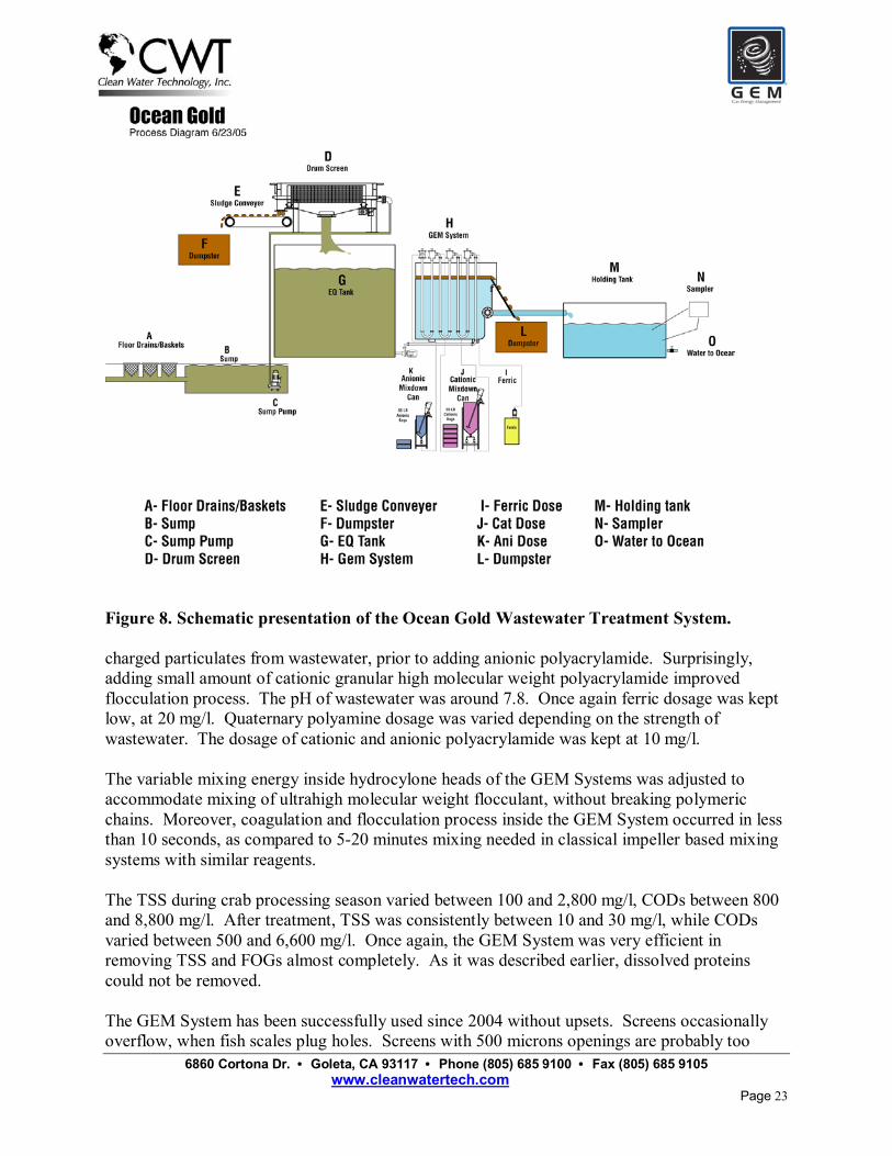
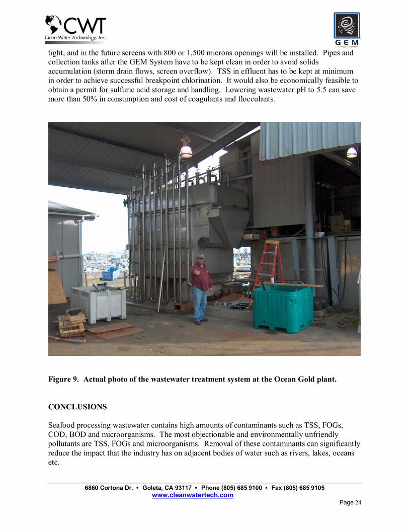
The knowledge resulting from laboratory and pilot plant studies has been implemented in several full-scale installations. This presentation describes the full-scale installation at Ocean Gold Seafood (OCS) plant in Westport, Washington, US. Ocean Gold Seafood Inc. is one of the larger fish processing companies in the Pacific Northwest. It processes up to 1.5 million lbs of fish per day. The main current products are pacific whiting fish and Dungeness crabs. Boat unloading as well as fish and crab gutting, cleaning and storage result in production of up to 750,000 gallons of wastewater per day. Local Government requires that fish processors remove TSS, FOGs and colloidal materials in order to allow for efficient chlorination for subsequent fecal coliform removal. OCS plant had only a limited amount of space for wastewater treatment system. CWT and OCS teams designed the system with underground equalization and clean water collection/chlorination tanks (11,000 gallons each), 1/8 inch self � cleaning rotating drum perforated sheet screens (500 microns openings), coagulation, flocculation, hybrid dissolved air � centrifugal flotation (the GEM System), and chlorination � dechlorination. Figure 8 presents schematic illustrations of the implemented system. The GEM System built to treat 500 GPM of wastewater required only 8� - 16� area. Figure 9 is a photograph of the actual GEM System installed at the OCS plant. Coagulation, flocculation and GEM System flotation have been described in detail earlier in this manuscript. OCS team did not have approval for handling acids and caustic, consequently the pH of wastewater was �as received�. Most of the time, the pH is in the neutral range between 7.1 and 7.85. Ferric sulfate is used as coagulant to remove traces of blood color from wastewater. Dual flocculant approach described earlier is used to flocculate the particulates, while simultaneously nucleating bubbles inside the hydrocyclone columns of the GEM System. Ferric sulfate dosage is kept low (20 mg/l) to avoid bulky wet sludge production. Dosage of anionic flocculant is kept constant at 10 mg/l. Dosage of cationic flocculant is varied to satisfy charge requirement. This produces large porous flocs that are easy to float and drain up to 22% of solids loading in sludge. Removal of TSS and FOGs also significantly reduces odor problems. During pacific whiting processing season, TSS can vary between 50 and 3,000 mg/l, and CODs between 2,000 and 30,000 mg/l. After treatment, average TSS were 10-20 mg/l, FOGs 1mg/l and COD�s 2,000 mg/l. This allows for the successful breakpoint chlorination (25-50 mg/l of chlorine needed) and dechlorination, and fecal coliform removal to less than 200 per ml (99.995% reduction). As already explained earlier, numerous coagulation and flocculation strategies were tested. However, no chemical treatment was successful in removing more than 20% of proteins. During crab processing season, conductivity of wastewater was high, and varied between 6,000 and 22,000 micromhos/cm. Dissolved sodium calcium, chloride and sulfate ions interfere with the activation and flocculation performance of polyacrylamide flocculants. New generation of ultrahigh molecular weight anionic polyacrylamide was used to flocculate particulates in such streams. Ferric and cationic polyamine coagulants were used to overcharge initially negatively
6860 Cortona Dr. • Goleta, CA 93117 • Phone (805) 685 9100 • Fax (805) 685 9105 www.cleanwatertech.com
Page 23
Figure 8. Schematic presentation of the Ocean Gold Wastewater Treatment System. charged particulates from wastewater, prior to adding anionic polyacrylamide. Surprisingly, adding small amount of cationic granular high molecular weight polyacrylamide improved flocculation process. The pH of wastewater was around 7.8. Once again ferric dosage was kept low, at 20 mg/l. Quaternary polyamine dosage was varied depending on the strength of wastewater. The dosage of cationic and anionic polyacrylamide was kept at 10 mg/l. The variable mixing energy inside hydrocylone heads of the GEM Systems was adjusted to accommodate mixing of ultrahigh molecular weight flocculant, without breaking polymeric chains. Moreover, coagulation and flocculation process inside the GEM System occurred in less than 10 seconds, as compared to 5-20 minutes mixing needed in classical impeller based mixing systems with similar reagents. The TSS during crab processing season varied between 100 and 2,800 mg/l, CODs between 800 and 8,800 mg/l. After treatment, TSS was consistently between 10 and 30 mg/l, while CODs varied between 500 and 6,600 mg/l. Once again, the GEM System was very efficient in removing TSS and FOGs almost completely. As it was described earlier, dissolved proteins could not be removed. The GEM System has been successfully used since 2004 without upsets. Screens occasionally overflow, when fish scales plug holes. Screens with 500 microns openings are probably too
6860 Cortona Dr. • Goleta, CA 93117 • Phone (805) 685 9100 • Fax (805) 685 9105 www.cleanwatertech.com
Page 24
tight, and in the future screens with 800 or 1,500 microns openings will be installed. Pipes and collection tanks after the GEM System have to be kept clean in order to avoid solids accumulation (storm drain flows, screen overflow). TSS in effluent has to be kept at minimum in order to achieve successful breakpoint chlorination. It would also be economically feasible to obtain a permit for sulfuric acid storage and handling. Lowering wastewater pH to 5.5 can save more than 50% in consumption and cost of coagulants and flocculants.
Figure 9. Actual photo of the wastewater treatment system at the Ocean Gold plant. CONCLUSIONS Seafood processing wastewater contains high amounts of contaminants such as TSS, FOGs, COD, BOD and microorganisms. The most objectionable and environmentally unfriendly pollutants are TSS, FOGs and microorganisms. Removal of these contaminants can significantly reduce the impact that the industry has on adjacent bodies of water such as rivers, lakes, oceans etc.
6860 Cortona Dr. • Goleta, CA 93117 • Phone (805) 685 9100 • Fax (805) 685 9105 www.cleanwatertech.com
Page 25
The system that included screens, hybrid centrifugal � dissolved air flotation (the GEM System), coagulation, flocculation and breakpoint chlorination/dechlorination significantly reduced or eliminated such pollutants from wastewater. The efficiency of TSS and FOGs removal reached 99%. The reduction of COD/BODs depends on the amount of dissolved materials (mostly proteins) and varies between 15 and 82% (around 65% average was observed). Upon efficient removal of TSS and FOGs to less than 20 mg/l and 1 mg/l respectively, successful breakpoint chlorination enabled removal of fecal coliforms and other microorganisms. The GEM System produced sludge with more than 15% and up to 22% of solids. Small, dissolved protein molecules could not be removed.

6860 Cortona Dr. • Goleta, CA 93117 • Phone (805) 685 9100 • Fax (805) 685 9105 www.cleanwatertech.com
Page 26
REFERENCES Bratby, J.; Marais, G.V.R., (1977) Flotation. In Purchas D.B. (Ed.), Solid/Liquid Separation
Equipment Scale �Up. Upland Press, pp. 155-168. Carissimi, E.; Rubio, J. (2005) The Flocs Generator Reactor-FGR: A New Basis for Flocculation
and Solid-liquid separation. Int. J. Miner. Process., 75, 237-247. Clayton, R.; Jameson, G.J.; Manlapig, E.V. (1991) The Development and Application of
Jameson Cell. Mineral Engineering, 4, 925-933. Colic, M.; Morse, D.E.; Morse, W.O.; Matherly, T.G.; Carty, S.; Miller J.D. (2001) From Air-
sparged Hydrocyclone to Bubble Accelerated Flotation: Mineral Industry Technology sets Stage for Development of New Wastewater Treatment Flotation. Proceedings Engineering Foundation Conference, Froth Flotation/Dissolved Air Flotation: Bridging the Gap, UEF Conferences, Tahoe City, California, in press.
Da Rosa, J.; Rubio, J. (2005) The FF (flocculation-flotation) Process, in Minerals Engineering (web version available at www.elsevier.com/locate/mineng), in press.
Desam, P.R.; Datta, A.; Morse, W.; Miller, J.D. (2001) A Computational Fluid Dynamics (CFD) Model for a Bubble Separation Tank Used in Wastewater Treatment, Proceedings Engineering Foundation Conference, Froth Flotation/Dissolved Air Flotation: Bridging the Gap, UEF Conferences, Tahoe City, California, in press.
Fan, A.X.; Turro, N.J.; Somasundaran, P.; (2000) A Study of Dual Polymer Flocculation. Colloids Surf. A, 162, 141-148.
Feris, L.A.; De Leon, A.T.; Santander M.; Rubio, J. (2004) Advances in The Adsorptive Particulate Flotation Process, Int. J. Miner. Process., 74, 101-106.
Jameson, G.J. (1999) Hydrophobicity and Floc Density in Induced-air Flotation for Water Treatment. Colloids Surf. A, 151, 269-281.
Kiuri, H.J. (2001) Development of Dissolved Air Flotation Technology from the 1st Generation to the Newest 3rd one (very thick microbubbles) with High Flow-rates (DAF in turbulent flow conditions). Water Science and Technology, 8, 1-8.
Miller, J. D. (1981) Air-sparged Hydrocyclone and Method. US Pat. 4,279,743. Morse, D.E.; DeWitt, J.B.; Gnegy, B.; Hendrickson, E.D.; Jovine, R.; Matlick, A.; Matherly,
T.G.; Morse, W.O.; Owen, J.J.; (2000) Fluid Conditioning System and Method. US Pat. 6,106,711.
Morse, D.E.; Hendrickson E.D.; Jovine, R.; Morse, W.O.; Mandoza D.W.; (2001) Fluid Conditioning System. US Pat. 6,171,488.
Morse, D.E.; Morse, W.O.; Matherly T.G.; Hendrickson E.D. (2001) System and method to improve flotation systems. US Patent Application 20010032812.
Morse, D.E; Morse W.O; Matherly, T.G (2004a) System and method of gas energy management for particle flotation and separation. US Patent Application 20040178152.
Morse, D.E.; Morse, W.O.; Matherly, T.G. (2004b) Adjustable Contaminated Liquid Mixing Apparatus. US Patent Application 20040178153.
Owen, J.J.; Morse, D.E.; Morse, W.O.; Jovine, R. (1999) New Developments in Flotation Equipment for Water Treatment Systems, in Advances in Flotation Technology, B.K. Parekh and J.D. Miller, eds., SME, Littleton, Colorado, pp. 381-389.
Rubio, J; Souza, M.L., Smith, R.W. (2002) Overview of Flotation as a Wastewater Treatment Technique. Minerals Eng., 15, 139-155.

6860 Cortona Dr. • Goleta, CA 93117 • Phone (805) 685 9100 • Fax (805) 685 9105 www.cleanwatertech.com
Page 27
Tay, J. H.; Show, K-Y., Hung, Y-T. (2006) Seafood Processing Wastewater Treatment in Waste Treatment in the Food Processing Industry, L.K. Wang et al., eds., Taylor &Francis, Boca Raton, Florida, pp. 29-66.