case study: meyersdal
TRANSCRIPT

0 Case Study: Meyersdal
Case Study: Meyersdal
Rain and Grey Water Treatment Plants, Swimming Pool Treatment
and Filtration and Koi Pond Treatment and Filtration System for the
Proposed New Residence on Strand 720, Meyersdal Estate.
August 2014

1 Case Study: Meyersdal
Company Background
Branch Water Icon Head office
Address J2, Pinelands office park , Ardeer Road, Moddefontein , 1645
City, Province Johannesburg
Phone number +2711 608 3345
Country South Africa
Fax Number +27 11 608 3224
Contact Name Chris Ashmore
Title Marketing Manager : Business Development: Africa
Phone Number +27 84 851 9744
E-mail Address [email protected]
Project Name Rain and Grey Water Treatment Plants, Swimming Pool Treatment and Filtration and Koi Pond Treatment and Filtration System for the Proposed New Residence on Strand 720, Meyersdal Estate.
Customer Profile
Customer name Jock Lopes
Division Pvt
Address Strand 720, Meyersdal Est. Ext. 1. Jhb
City, Province Johannesburg, Gauteng
Phone number 083 460 6422
Country South Africa
E-mail Address [email protected]
Industry Pvt

2 Case Study: Meyersdal
Technical Situation
A private customer recently began construction on a new residence in Meyersdal. With an objective
to reduce waste, the customer approached Water Icon requesting the design a zero-liquid discharge
solution for his new residence. The aim was to recycle and reuse water on the property. This
included the design of a grey water recovery system and rain water recovery system. Additionally he
required the construction of a koi pond and swimming pool.
Solution
Water Icon was tasked with completing several water treatment solutions namely: A Rain Water
Recovery System, A Grey Water Recovery System, A Koi Fish Pond System and Swimming Pool
System.
RAIN WATER RECOVERY SYSTEM
The Rain Water Recovery System is capable of handling rain water collected from the roof structures
of the above residence buildings and the rain water is subsequently stored in three separate holding
tanks constructed for the purpose of raw rain water storage. The collected rain water is filtered to
remove suspended solids. A pH corrector is introduced to the water to correct the pH after which
the water is disinfected, fed to a clean water storage tank constructed for the purpose of treated
clean water storage. In this treated clean water storage tank the water will be circulated, filtered and
disinfected on a continuous basis to keep the quality of the water of high standard while at the same
time boosting the water to a pressure suitable for feed to the reticulation network of the residence.
This system will be capable of handling the raw rain water and producing treated water fit for
human consumption, within the limits of the TDS of the raw rain water.
3 Case Study: Meyersdal
Process Description
Summary of Rain Water Recovery and Treatment System
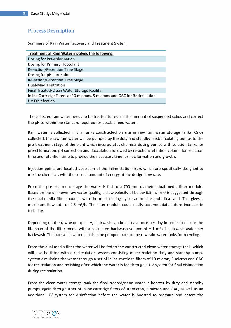
Treatment of Rain Water involves the following:
Dosing for Pre-chlorination Dosing for Primary Flocculant Re-action/Retention Time Stage Dosing for pH correction Re-action/Retention Time Stage Dual-Media Filtration Final Treated/Clean Water Storage Facility Inline Cartridge Filters at 10 microns, 5 microns and GAC for Recirculation UV Disinfection
The collected rain water needs to be treated to reduce the amount of suspended solids and correct
the pH to within the standard required for potable feed water.
Rain water is collected in 3 x Tanks constructed on site as raw rain water storage tanks. Once
collected, the raw rain water will be pumped by the duty and standby feed/circulating pumps to the
pre-treatment stage of the plant which incorporates chemical dosing pumps with solution tanks for
pre-chlorination, pH correction and flocculation followed by re-action/retention column for re-action
time and retention time to provide the necessary time for floc formation and growth.
Injection points are located upstream of the inline static mixers which are specifically designed to
mix the chemicals with the correct amount of energy at the design flow rate.
From the pre-treatment stage the water is fed to a 700 mm diameter dual-media filter module.
Based on the unknown raw water quality, a slow velocity of below 6.5 m/h/m2 is suggested through
the dual-media filter module, with the media being hydro anthracite and silica sand. This gives a
maximum flow rate of 2.5 m3/h. The filter module could easily accommodate future increase in
turbidity.
Depending on the raw water quality, backwash can be at least once per day in order to ensure the
life span of the filter media with a calculated backwash volume of ± 1 m3 of backwash water per
backwash. The backwash water can then be pumped back to the raw rain water tanks for recycling.
From the dual media filter the water will be fed to the constructed clean water storage tank, which
will also be fitted with a recirculation system consisting of recirculation duty and standby pumps
system circulating the water through a set of inline cartridge filters of 10 micron, 5 micron and GAC
for recirculation and polishing after which the water is fed through a UV system for final disinfection
during recirculation.
From the clean water storage tank the final treated/clean water is booster by duty and standby
pumps, again through a set of inline cartridge filters of 10 micron, 5 micron and GAC, as well as an
additional UV system for disinfection before the water is boosted to pressure and enters the

4 Case Study: Meyersdal
reticulation system of the residence, with a backup mains feed solenoid valve and non-return valve
system, in place for when there is a shortage of rain water. This solenoid valve system and the level
probes in the clean water storage tank together with the required timer system will ensure that the
residence is fed with mains water when no rain water is available.
Storage Tank – Rain Water System Dosing System – Rain Water System
Pump System – Rain Water System Filtration System – Rain Water
System

5 Case Study: Meyersdal
Figure 1: Schematic of Rain Water Recovery System

6 Case Study: Meyersdal
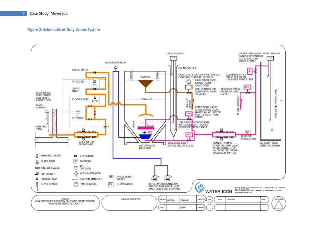
GREY WATER RECOVERY SYSTEM
The grey water is treated to remove cleaning agents, soaps, shampoo, body oils and lotions as well
as neutralize the pH so that the water can be fit for irrigation purposes.
The Grey Water Recovery and Treatment System involves the following:
Flow and pH Monitoring Dosing for Primary Flocculant, Static Mixing Dosing for pH Correction Static Mixing Batch re-action/retention tank system with time controlled aeration/floatation process complete with auto skimming spill, decant and de-sludge facilities
Process Description
A tank constructed on site as the grey water storage tank for grey water collection will collect all the grey water from where it will be pumped by the duty and standby grey water feed pumps, through the pre-treatment stage of the plant. Pre-treatment incorporates mechanical flow measurement and pH monitoring, chemical dosing pumps with solution tanks for pH correction and flocculation followed by a batch re-action/retention treatment tank for aeration, floatation and separation where the grey water is finally processed and de-natured to a condition fit for irrigation purposes only. Injection points are located upstream of the inline static mixers which are specifically designed to mix the chemicals with the correct amount of energy at the design flow rate. From the batch re-action/retention treatment tank the processed water will be fit for irrigation after the aeration, floatation and separation process. The processed water will then be decanted directly from the batch re-action/retention treatment tank by the client’s irrigation pump system and then be fed to the irrigation stations. As soon as the processed water level in the batch re-action/retention treatment tank reaches a low level the irrigation system will switch over to the raw rain water tanks for additional irrigation feed water. The process control in the batch re-action/retention treatment tank will be an automated function based on pre-set times and level control with a manual override system.
Grey Water System
7 Case Study: Meyersdal
Figure 2: Schematic of Grey Water System

8 Case Study: Meyersdal
KOI FISH POND SYSTEM
The system design makes provision for bio-filtration, dual media pressure filtration and circulation to
ensure good quality water in the koi fish pond. The filtration, bio-filtration, aeration, circulation and
surface skimming of the koi fish pond have been optimised.
Koi Pond Specs
Approximate Area 103 m2
Average Depth 1.5 m
Volume of Pond 155 m3
Turnover Rate: Dual-Media Filtration System 2 hours
Turnover Rate: Bio-filtration System 2 hours
Process Description
The principle on which the water feature system operates is based on two separate filtration circuits
- one through a bio-filter and the second through dual-media filter as well as a circulation circuit
system.
For the bio-filter to work it is essential that the system operate 24 hours a day. The bio-filter relies
on the growth of specific bacteria on the bio-filter media and these organisms will die if the water
flow is stopped for more than a few hours. Clearly this can be recovered however, to do this on a
daily basis is self-destructing and the bio-filter will then not function properly.
The bio-filter system for the koi fish pond comes with:
Corrugated plastic biological media blocks of 600 x 600 x800 high blocks
2 x sets of duty and standby air blower system
4 x airlifts
Isolating and control valves
Under drain suction from the bottom of the bio-filter
Return-to-pond piping
Airlift discharge pipe work to discharge the treated water over the weirs in the pond
The system also assumes that the dual-media filter run continuously all the time. Without these
conditions the plant cannot be expected to operate properly. Allowance has been made for a
dual-media filtration system for the koi fish pond complete with duty and standby feed pumps,
isolating and control valves, suction from and return-to-pond piping as well as discharge.
Allowance has been made for two separate duty and standby circulation pumps set systems to feed
water over the weirs at a certain calculated flow rate to ensure and optimize the surface skimming
of the water in the koi fish pond at all times to prevent any build-up of debris in stagnant areas
inside the koi fish pond. These circulation pump sets are complete with isolating and control valves,
suction from the floor of the koi fish pond and return-to-nozzle manifold piping as well as the
required bubbler nozzles.

9 Case Study: Meyersdal
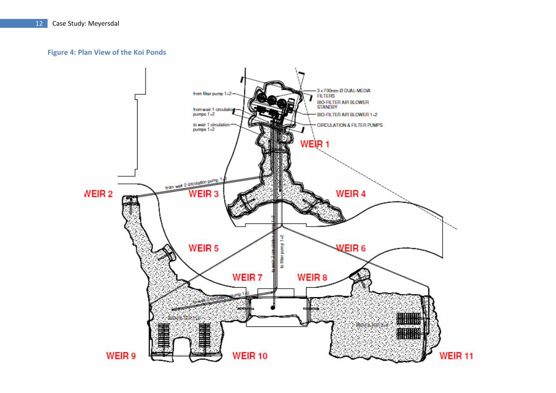
11 weirs are constructed as part of the koi fish pond structure to help provide the necessary surface
skimming required. Water runs over these weirs from one pond to another which is situated at a
lower level until the water eventually runs into the lowest pond from where it is then pumped back
to the top pond via the dual-media filtration and circulation systems.
10 Case Study: Meyersdal
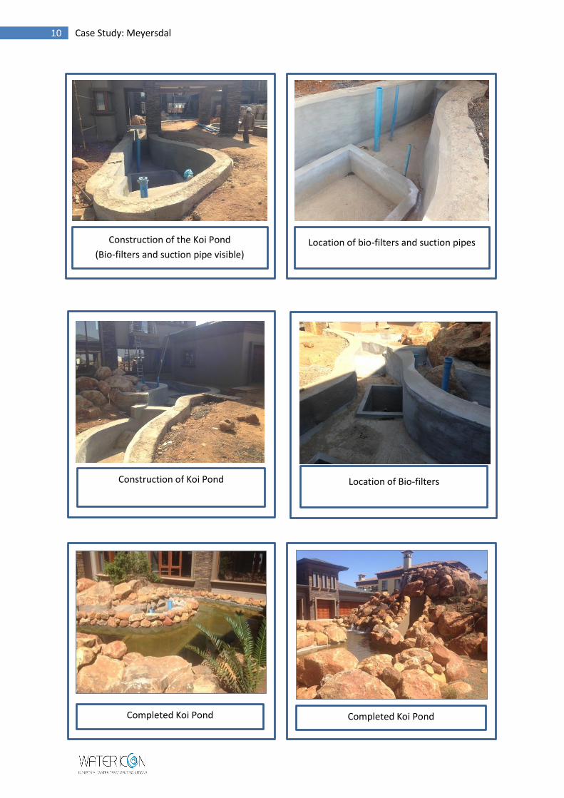
Location of Bio-filters Construction of Koi Pond
Completed Koi Pond Completed Koi Pond
Construction of the Koi Pond
(Bio-filters and suction pipe visible) Location of bio-filters and suction pipes

11 Case Study: Meyersdal
Figure 3: Schematic of the Koi Pond Design
12 Case Study: Meyersdal
Figure 4: Plan View of the Koi Ponds

13 Case Study: Meyersdal
SWIMMING POOL SYSTEM
Swimming Pool System Specs
Approximate Area 25 m2
Average Depth 1.46 m
Volume of Pool 42 m3
Turnover Rate 3 hours
Flow Rate 14 m3/hr
The pool has a rim flow on three sides of the pool along the width and both side lengths of the pool
from where the water would overflow to an overflow channel created along these two sides of the
pool, which runs into the balance tank inside the plant room next to the pool. The overflow of water
caused by splashing inside the pool would also end up in the overflow channel. The volume of this
overflow channel should be approx. 0.5 m3
The dual-media filter system has been selected together with filter pump, automated multi-port
valve system, isolating and control valves, suction from the balance tank and floor drains in the pool
floor and return-to-pool piping as well as discharge nozzles.
The filter pump system will pump water from the balance tank and floor drains in the pool floor via
the dual-media filter system back to the pool through the inlet discharge nozzles in the pool from
where the water would run over the rim flow back into the overflow channel, also creating the
required skimming action for the surface of the water.
Allowance has been made for a separate duty and standby circulation pump set system to feed
water over the rim of the swimming pool into the overflow channel to always ensure the same
amount of flow over the weir at all times to prevent any dry patches when the flow of water reduces
due to the loading on the filtration system. This circulation pump set comes complete with isolating
and control valves, suction from the balance tank and return-to-nozzle manifold piping.
A 26 g/hr Pentair IntelliChlor Electrolytic Salt Chlorinator has been included for disinfection. This is
the most effective and convenient way to keep pool water sparkling clean. The IntelliChlor unit uses
common table salt to produce all the chlorine the pool needs, right in the pool—safely, effectively
and automatically including the initial salt loading, complete with, fittings pipe work and controls.
Allowance has been made for low level protection on the filter pump and a set of filling probes to
operate the auto filling solenoid.
Pool filling is accomplished by monitoring the level in the balance tank of the pool during running
conditions by a probe that automatically opens the filling solenoid valve. For this purpose a separate
50mm pipe from the balance tank of the pool to the plant room must be allowed for.
A switchboard manufactured from injection-moulded polyester resin has been provided. The
switchboard is completely corrosion-free. It is fitted with normal Klockner Moeller and other EEC
standard equipment. There is ample space for each drive, which consists of a magnetic circuit
breaker, thermal over-load protection and a suitably rated contactor for the filter pump motor.

14 Case Study: Meyersdal
Swimming Pool Swimming Pool
15 Case Study: Meyersdal
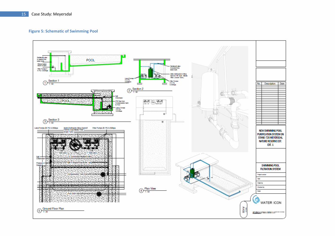
Figure 5: Schematic of Swimming Pool