cast carbon, stainless and alloy steel...
TRANSCRIPT

Catalog: POW-CS-12-r1
CAST CARBON, STAINLESS AND ALLOY STEEL VALVES
GATE, GLOBE AND CHECK VALVES
API 600 / API RP 591 / ASME CLASS 150 TO 2500 / 1” TO 60”

1
SUBJECT PAGE
THE WM. POWELL COMPANY—PROFILE 2-3
HOW TO ORDER 5
FUGITIVE EMISSIONS 6
GATE VALVES 7-9
GLOBE VALVES 10-12
NON-RETURN VALVES 13-14
SWING CHECK VALVES 15-17
TILTING DISC VALVES 18-20
ACCESSORIES 21-24
ENGINEERING DATA 25-54
TERMS AND CONDITIONS 55-57
POWELL’S STANDARD MATERIAL INSPECTION FLOW 4

2
The Wm. Powell Company - Profile The Wm. Powell Company is very proud of our achievements and our evolution in the past 165 years. We like to refer to ourselves as 166 years young due to our flexibility in changing quickly to our customer and the industry’s needs. Our business strategy is to maintain excellent customer service. We will continue to focus on manufacturing the best of class products both in design fea-tures and quality, at competitive prices. The Wm. Powell Company’s products include a wide variety of valves in bronze, iron, steel, and corrosion resistant alloys for class 125 to class 4500 pressure service. Our experience as pioneer in the development of industrial valves encompasses over a century and a half of craftsmanship and valve know-how. Through modern engineering, laboratory, research and testing facilities, the Wm. Powell Company has been a leader in changes in our industry. Our on-going program is a long-term commitment to the valve industry and is poised for significant future growth. Powell Valves has endured a Civil War, World Wars I and II, and the Korean and Vietnam Wars. Powell rebuilt after floods, U.S. economic disaster in the Great Depression, and fierce foreign com-petition to help put men on the moon. Whether it was the “Manhattan Project”, projects on U.S. Nuclear Submarines, Titan or Atlas rockets, in Nuclear Power plants, at Chemical or Petroleum plants, Pulp and Paper mills, or the harshness of cryogenic use, Powell Valve has a long tradition of quality in temperatures from – 425°F to 1500°F and pressures from Class 125 to 4500. Powell’s market base is the Industrial Users: Petrochemical, Industrial Gas, Pulp & Paper, Pharma-ceutical, Hydrocarbon processing, Food processing, Mining, Power Generation, Pipeline, Chemi-cal, and Mechanical construction. Powell has formed business partnerships with industrial end-users, contractors, distributors and A&E’s in the United States and around the World. Business partnerships formed on competitively priced product, on-time delivery, service and our tradition of product reliability. Powell’s network of support and product availability is unmatched. Powell offers the most com-plete multi-turn product line from a single source manufacturer. Powell’s products are of the high-est quality standards, are competitively priced and are produced with modern manufacturing tech-nology and astute materials sourcing, with strategic purchasing & financial ventures in place. Powell’s diverse products and services, industry knowledge, project capabilities and reputation, coupled with our high quality distribution network, create a win-win arrangement where the end-user, contractor, distributor and manufacturer can benefit. The Wm. Powell Company has made a commitment to our industry to increase growth and market share, with quality competitive products and services and on-time delivery. This is a global com-mitment. Powell’s end user customers have to react quickly to the demands that are on them to expand their businesses by implementing increased capacity and introducing new products into the market place at low costs and fast turn around times. Powell has addressed our customer’s needs by in-creasing finished product inventory to over $35,000,000 USD in the U.S.A. and with inventory hubs in Asia and Europe. As an additional advantage to our domestic and global customers, The Wm. Powell Company’s Manning, SC facility is a Registered Free Trade Zone.
3
Powell also used its valve knowledge and expertise to construct a modification facility in the U.S.A. to assist customers with their needs, such as, automation, trim changes, end connection changes, additional quality inspections and special service pressure testing requirements, field service, etc… The Wm. Powell Company is a closely held private corporation that has been in business since 1846. In fact, only nine presidents have led the Company through its 166, plus, years. The fact that we have been a healthy corporation during this period of time, having survived wars, depressions and natural disasters – in a very competitive marketplace – speaks well for itself. We look forward to further discussing ways that The Wm. Powell Company can capture current and future opportunities together. Again, The Wm. Powell Company thanks you for your interest in our company, our products and services. Powell looks forward to discussing ways to be your Preferred Valve Supplier. If you should have any questions, or comments, please contact us. Sincerely, Randy Cowart President, CEO & Chairman The Wm. Powell Company

4
POWELL’S STANDARD MATERIAL INSPECTION FLOW

5
How
to O
rder
Pow
ell C
ast B
olte
d B
onne
t and
Pre
ssur
e Se
al V
alve
s Th
e fig
ure
num
ber s
yste
m o
utlin
ed b
elow
is d
esig
ned
to c
over
the
mos
t com
mon
con
figur
atio
ns.
If sp
ecia
l fea
ture
s are
requ
ired
whi
ch a
re n
ot li
sted
belo
w, p
leas
e
advi
se th
e de
taile
d de
scrip
tion
for a
ccur
ate
proc
essi
ng.
Dig
it
1 2
3 4
5 6
7 8
9 10
11
12
13
14
15
Size
B
lank
B
ase
Figu
re N
umbe
r En
d C
ode
Mat
eria
l C
ode
Trim
Pa
ckin
g/G
aske
t O
ptio
n C
ode
6
. 0
1
5 0
3 F
C
8 G
X
X
X
Size
Cod
e
Base
Fig
ure
Num
ber
En
d C
ode
M
ater
ial C
odes
Trim
Pack
ing/
Gas
ket
Cod
e
Size
C
ode
Des
crip
tion
C
ode
Opt
ion
C
ode
Opt
ion
C
ode
Opt
ion
0.1
⅛”
A
Sch.
100
C
A21
6 W
CB
0
API
Trim
10
G
Std
Gra
phite
0.2
¼"
B Sc
h. 1
40
D
A
217
WC
6
1 A
PI T
rim 1
T St
d PT
FE
0.4
⅜”
Four
dig
it ba
se fi
gure
nu
mbe
r. S
ee p
rodu
ct
page
for f
igur
e nu
mbe
r.
C
125
RMS
Max
E A
217
WC
9
2 A
PI T
rim 1
2
X
N
one
0.5
½"
D
B16
.47
Serie
s B F
lg.
F
A21
7 C
5
3 A
PI T
rim 1
3
Z
Spec
ial P
acki
ng o
r Gas
ket
0.8
¾"
E
Flat
Fac
e Fl
g.
G
A
217
C12
5 A
PI T
rim 5
M
Pack
ing
PTFE
, Gas
ket
Gra
phite
1.0
1”
F Fl
g. E
nd
H
A
217
C12
A
6
API
Trim
16
R St
d G
raph
ite, R
ing
Join
t G
aske
t 1.
2 1¼
”
G
B16
.47
Serie
s A F
lg.
J
A35
2 LC
B
7 A
PI T
rim 1
7
1.5
1½”
H
Sc
h 10
/10S
K
A35
2 LC
C
8 A
PI T
rim 8
Opt
ion
Cod
es
2.0
2”
I
Sch
40/4
0S
L
A21
6 W
CC
9
API
Trim
9
C
ode
Opt
ion
2.5
2-”
J
Sch
80/8
0S
A
A
351
CF8
(304
)
A
Inte
gral
hal
f H
F
X
XX
N
o O
ptio
ns
3.0
3”
K
Sc
h 12
0
B A
351
CF3
(304
L)
B
Inte
gral
full
HF
BX
X
Sing
le V
alve
Byp
ass
4.0
4”
L
Sch
160
M
A
351
CF8
M (3
16)
C
Inte
gral
BA
1 Tw
o V
alve
Byp
ass
5.0
5"
M
Sc
h X
S
N
A35
1 C
F3M
(316
L)
D
A
PI T
rim 1
1
B
A2
Two
Val
ve B
ypas
s w/
Dra
in V
alve
6.0
6”
N
Sc
h X
XS
P
A35
1 C
G8M
(317
)
E A
PI T
rim 2
BA
3 O
ne V
alve
Byp
ass w
/Dra
in
Val
ve
8.0
8”
P
Sch
60
Q
A
351
CG
3M (3
17L)
N
API
Trim
8
NA
CE
BA
4 D
rill &
Tap
@ P
ositi
on G
10.
10”
R
RTJ
End
s
R A
351
CF8
C (3
47)
Z
Spec
ial T
rim
B
VX
B
onne
t Ven
t
12.
12”
W
Sc
h ST
AN
DA
RD
Z Sp
ecia
l Mat
eria
l
G
XX
G
ear O
pera
tor
14.
14"
Z
Spec
ial e
nds
G
A5
Gea
r, 1.
25" H
ex
16.
16"
GB
P G
ear,
Sing
le V
alve
B
ypas
s 18
. 18
"
G
CA
G
ear,
Lock
ing
Dev
ice
20.
20"
GB
1 G
ear,
Post
ion
Ind.
24
. 24
"
Exam
ples
:
PL
L Li
ve L
oad
30.
30"
6.
0 15
03FC
8GX
XX
6"
Fig
ure
1503
Fla
nged
end
, WC
B, t
rim 8
, gra
phite
PLR
La
nter
n R
ing
36.
36"
3.
0 15
03FG
8GX
XX
3"
Fig
ure
1503
Fla
nged
end
, C12
, trim
8, g
raph
ite
FR
T R
adio
grap
hy
48.
48"
3.
0 24
67JN
2TX
XX
3"
Fig
ure
2467
Sch
. 80S
, CF3
M, t
rim 1
2, P
TFE
H
LD
Lock
ing
Dev
ice
etc.
et
c.
8.
0 60
03JD
5GG
XX
8"
Fig
ure
6003
Sch
. 80,
WC
6, tr
im 5
, gra
phite
, gea
r ope
rato
r
CN
X
Oxy
gen
Cle
an N
on-E
xt

6
BRAIDED CARBON YARN END RINGS WITH CORROSION INHIBITOR
DIE FORMED FLEXIBLE GRAPHITE RIBBON INNER RINGS WITH CORROSION INHIBITOR
BELLEVILLE WASHERS
STANDARD PACKING ARRANGEMENT
Powell standard design cast steel valves are designed and manufactured to a 100 ppm maximum fugitive emissions level.
LIVE LOAD OPTION
Live load design with standard packing. Live load washers help maintain packing load to reduce frequency of packing adjustment.
BODY/BONNET GASKETS
RING JOINT SPIRAL WOUND SHEET
Corrugated 316 stainless steel totally encapsulated with graphite. Standard gasket arrangement for class 150 valves.
Stainless steel spiral wound gasket with graphite fill and gauge ring for controlled compression. Standard gasket arrangement for class 300-600 valves.
ASME B16.20 ring joint gasket with material at least equal to body. Standard gasket arrangement for class 900-1500 valves. Optionally available on most other valves.
LANTERN RING OPTION
LANTERN RING Lantern ring design and other special packing arrangements available. The lantern ring arrange-ment consists of two packing sets with lantern spacer between the sets. The bonnet connection at the lantern ring location allows monitoring of leakage past packing set.

7
API 600 GATE VALVES BOLTED BONNET, ASME CLASSES 150 TO 1500 CAST CARBON, STAINLESS STEEL OR ALLOY STEEL
DESIGN FEATURES: • Flexible Wedge for improved seat-
ing and ease of operation, espe-cially in high temperature service. Wedges are accurately guided thru the entire stroke.
• Standard trim is API trim 8 for carbon steel valves, API trim 5 for chrome alloy valves, and API trim 10 for CF8M (T316) valves for optimal performance under normal conditions. Other trim materials available on request.
• Seat faces lapped for smooth finish and superior sealing.
• Stems are non-rotating with sur-face finish to maximize packing seal for low fugitive emissions.
• Bonnet and Yoke arms designed for ease of gear, motor or cylinder actuator adaptation.
• Each valve is shell, seat and back-seat pressure tested per industry standard API 598.
• Gland is two piece gland / gland flange design for optimal alignment and uniform packing compression.
• End Flanges have the following raised faces per ASME B16.5:
Classes 150-300: 1/16” (2mm). Classes 600-1500: 1/4” (7mm). • Weld ends are available per ASME B16.25
or per customer’s specification. • Each valve has a unique certification number
that is traceable to the valve certification sheet which includes MTR data, pressure test report, inspection report and certificate of conformance.
• Other available options as follows: -Alternate valve materials such as chrome and stainless steel alloys -Alternate trim materials -Bypass, drain and other auxiliary connections -Gear, motor, and cylinder actuators available -NACE service -Special cleaning for applications such as oxygen or chlorine -Other options available as specified
Class Fig. No. 150 1503 300 3003 600 6003 900 9003
1500 1303
Item Applicable Specification Wall thickness API 600
Pressure - temperature ratings ASME B16.34 General valve design API 600 & B16.34
End to End dimensions ASME B16.10 Flange design ASME B16.5
Butt Weld design ASME B16.25 Materials ASTM
Design Specifications
(1) Weld end valve body A351 Gr. CF3M
NOTE: See page 52 for flow, safety and maintenance information.
STANDARD MATERIALS (Other materials available) PART MATERIALS
Body A216 Gr. WCB (STANDARD) A217 Gr. WC6 A217 Gr. WC9 A351 Gr. CF8M (1)
Bonnet / Yoke arm A216 Gr. WCB A217 Gr. WC6 A217 Gr. WC9 A351 Gr. CF8M
Wedge A217 Gr CA15 or WCB + 13% CR Faced
WC6 + Stellite 6 Faced A351 Gr. CF8M
Seat Ring Carbon Steel + Stellite 6 Faced
A182 F11 + Stellite 6 Faced
A182 F22 + Stellite 6 Faced SST 316
Stem SST 410 SST 316 Stem Bushing A 439 Ductile NI-Resist Gr. D2
Stem Bushing Lock Nut Steel SST 316
Gland Flange Carbon Steel Series 300 SST Eye Bolt A193 Gr. B7 A193 Gr. B8
Eye Bolt Nut A194 Gr. 2H A194 Gr.8 Groove Pin Steel Series 300
Gland SST 410 SST 316 Packing Graphite PTFE
Packing Washer / Packing Spacer SST 410 SST 316
Gasket
Class 150: Corrugated SST Encapsulated w/ Graphite Class 150: PTFE Class 300 to 600: Spiral Wound SST with Graphite Class 300-600: Spiral
Wound SST with PTFE Class 900-1500: RTJ
Back Seat SST 410 SST 316 Hand Wheel Malleable Iron or Steel
Hand Wheel Nut Malleable Iron or Steel Key Steel
Lubricant Fitting Steel Body / Bonnet Stud A193 Gr. B7 A193 Gr. B16 A193 Gr. B8 Body / Bonnet Nut A194 Gr. 2H A194 Gr. 7 A194 Gr.8
Bearing Cap Carbon Steel Series 300 SST Cap Screws Steel Identification Plate Series 300 SST
WC9 + Stellite 6 Faced

8
GATE VALVE DIMENSIONS (CLASS 150—1500).
(1) Gear operators stan-dard for 18” and up class 300 and 14” and up class 600. Height is to top of actuator.
SIZE ASME 900 ASME 1500
in A B(1) C(1) D E
A B(1) C(1) D E
mm WE/FE WE/FE
2 14.50 15.8 18.5 1.87 10 14.50 15.8 18.5 1.87 10
50 368 402 470 48 254 368 402 470 48 254
2 ½ 16.50 18.7 22.1 2.25 12 16.50 18.7 22.1 2.25 12
65 419 475 561 57 305 419 475 561 57 305
3 15.00 19.5 23.1 2.87 14 18.50 20.4 24.1 2.75 16
80 381 495 588 73 350 470 518 613 70 400
4 18.00 21.4 25.8 3.87 14 21.50 22.1 26.5 3.62 16
100 457 543 655 98 350 546 561 674 92 400
6 24.00 30.4 37.3 5.75 22 27.75 32.9 40.2 5.37 24
150 610 773 948 146 560 705 836 1021 136 610
8 29.00 34.7 43.4 7.50 24 32.75 48.0 56.5 7.00 26
200 737 882 1102 191 610 832 1219 1435 178 660
10 33.00 40.6 51.2 9.37 30 39.00 57.8 68.2 8.75 30
250 838 1030 1300 238 762 991 1467 1734 224 762
SIZE ASME 150 ASME 300 ASME 600 in A B(1) C(1) D E A B(1) C(1) D E A B(1) C(1) D E mm FE WE WE/FE WE/FE 1 5.00 5.00 8.6 9.8 1.00 4 6.50 8.6 9.8 1.00 4 - - - - -
25 127 127 217 248 25 114 165 217 248 25 114 - - - - - 1 ½ 6.50 6.50 10.7 12.4 1.50 6 7.50 10.7 12.4 1.50 6 - - - - - 40 165 165 271 314 38 152 190 271 314 38 152 - - - - - 2 7.00 8.50 12.3 14.6 2.00 7 8.50 12.3 14.6 2.00 7 11.50 13.5 15.7 2.00 8
50 178 216 313 372 51 178 216 313 372 51 178 292 342 400 51 203 2 ½ 7.50 9.50 12.8 15.6 2.50 7 9.50 12.8 15.6 2.50 7 13.00 18.1 21.9 2.50 12 65 190 241 324 395 64 178 241 324 395 64 178 330 461 555 64 305 3 8.00 11.12 14.8 18.1 3.00 9 11.12 15.9 19.3 3.00 9 14.00 19.2 22.8 3.00 12
80 203 282 375 459 76 230 282 405 490 76 230 356 487 580 76 305 4 9.00 12.00 17.7 22.1 4.00 10 12.00 19.0 23.3 4.00 10 17.00 23.0 27.5 4.00 14
100 229 305 450 561 102 254 305 482 593 102 254 432 585 698 102 356 5 10.00 15.00 24.4 31.1 5.00 12 15.00 26.5 33.1 5.00 14 - - - - -
125 254 381 620 789 127 305 381 674 842 127 356 - - - - - 6 10.50 15.88 24.4 31.1 6.00 12 15.88 26.5 33.1 6.00 14 22.00 32.5 39.1 6.00 20
150 267 403 620 789 152 305 403 674 842 152 356 559 825 993 152 508 8 11.50 16.50 30.7 39.2 8.00 14 16.50 32.8 41.4 8.00 16 26.00 35.0 45.4 7.87 22
200 292 419 780 996 203 356 419 833 1051 203 406 660 890 1154 200 560 10 13.00 18.00 36.4 47.2 10.00 16 18.00 39.4 50.3 10.00 20 31.00 41.9 52.4 9.75 24 250 330 457 925 1198 254 406 457 1002 1277 254 508 787 1065 1332 248 610 12 14.00 19.75 42.7 55.6 12.00 20 19.75 44.8 57.7 12.00 20 33.00 47.3 59.9 11.75 28 300 356 502 1084 1412 305 508 502 1139 1466 305 508 838 1202 1521 298 710 14 15.00 22.50 47.5 61.5 13.25 20 30.00 49.1 63.4 13.25 22 35.00 67.4 (1) 12.87 28 350 381 572 1207 1562 337 508 762 1248 1611 337 560 889 1712 327 710 16 16.00 24.00 51.7 67.8 15.25 22 33.00 54.5 70.7 15.25 24 39.00 75.2 (1) 14.75 36 400 406 610 1313 1722 387 560 838 1384 1796 387 610 991 1910 375 915 18 17.00 26.00 58.1 76.4 17.25 24 36.00 79.2 (1) 17.00 28 43.00 81.1 (1) 16.50 36 450 432 660 1477 1940 438 610 914 2012 432 710 1092 2060 419 915 20 18.00 28.00 63.3 83.3 19.25 28 39.00 87.3 (1) 19.00 28 47.00 87.3 (1) 18.25 28 500 457 711 1615 2123 489 710 991 2217 483 710 1194 2217 464 710 24 20.00 32.00 76.7 101.1 23.25 28 45.00 102.9 (1) 23.00 36 55.00 104.3 (1) 22.00 32 600 508 813 1948 2568 591 710 1143 2614 584 915 1397 559 810 30 24.00 36.00 91.9 123.0 29.25 24 55.00 130.0 (1) 29.00 24
750 610 914 2334 3125 743 610 1397 3302 737 610 36 28.00 40.00 107.4 143.1 34.50 24
900 711 1016 2729 3635 876 610 42 31.00 44.00 131.7 173.8 40.25 24
1050 787 1118 3345 4415 1022 610
2649
WE = Butt weld ends FE = Flanged ends B = Center to top closed C = Center to top open
ADDITIONAL SIZES, MATERIALS AND CLASSES AVAILABLE UPON REQUEST.

9
SIZE ASME 150 ASME 300 ASME 600 in F in WT lb WT lb CV F in WT lb WT lb CV F in WT lb WT lb CV mm mm FE kg WE kg mm FE kg WE kg mm FE kg WE kg 1 12.0 14 12 90 12.0 19 15 90 - - - -
25 305 6 5 305 9 7 - - - - 1 ½ 15.5 25 22 190 15.5 34 25 190 - - - - 40 390 11 10 390 15 11 - - - - 2 19.0 35 33 240 19.0 42 33 240 20.0 77 57 240
50 475 16 15 475 19 15 505 35 26 2 ½ 19.5 49 44 390 19.5 55 44 390 26.0 148 126 390 65 500 22 20 500 25 20 655 67 57 3 22.0 72 62 560 24.0 112 73 560 28.0 174 143 560
80 565 33 28 610 51 33 710 79 65 4 26.5 112 97 1000 29.0 176 135 1000 33.5 315 251 1000
100 675 51 44 735 80 61 850 143 114 5 36.0 142 - 1600 39.0 225 - 1600 - - - -
125 915 64 - 990 102 - - - - - 6 36.0 203 190 2400 39.0 346 273 2400 46.5 677 573 2400
150 915 92 86 990 157 124 1185 307 260 8 45.5 320 287 4500 48.5 540 430 4500 54.5 1096 942 4300
200 1155 145 130 1230 245 195 1380 497 427 10 53.0 507 465 7000 58.5 838 692 7000 62.0 1574 1334 6700
250 1350 230 211 1480 380 314 1580 714 605 12 63.0 721 662 10000 67.0 1162 955 10000 71.0 2000 1702 10000
300 1600 327 300 1705 527 433 1805 907 772 14 70.5 988 966 13000 74.0 1555 1277 13000 76.0 2761 2373 12000
350 1795 448 438 1875 705 579 1935 1252 1076 16 78.0 1191 1111 17000 82.0 1949 1663 17000 85.0 3616 3098 16000
400 1985 540 504 2080 884 754 2150 1640 1405 18 85.0 1433 1299 23000 89.5 3790 2196 22000 91.5 4507 3861 21000
450 2150 650 589 2270 1720 996 2325 2044 1751 20 95.0 1744 1678 28000 98.0 4230 2745 27000 100.0 4507 4279 25000
500 2415 791 761 2505 1918 1245 2520 2044 1941 24 112.5 2580 2481 41000 116.0 6850 4500 40000 116.5 7949 7621 37000
600 2860 1170 1125 2945 3100 2040 2960 3605 3457 30 133.5 5510 * 65000 132.5 7932 * 64000
750 3395 2500 * 3365 3600 * 36 155.5 7453 * 90000
900 3950 3380 * 42 192.0 11687 * 120000
1050 4875 5300 *
API 600 GATE VALVES BOLTED BONNET, ASME CLASSES 150 TO 1500 CAST CARBON, STAINLESS STEEL OR ALLOY STEEL
FE = Flanged Ends WE = Weld Ends WT = Weight F = Dismantling Dimension CV = Flow Coefficient
(*) Weld ends are available on request.
SIZE ASME 900 ASME 1500 in
F in WT lb WT lb
CV F in WT lb WT lb
CV mm mm FE kg WE kg mm FE kg WE kg
2 23.5 176 141 210 23.5 176 141 210 50 595 80 64 595 80 64
2 ½ 29.0 210 176 310 29.5 386 316 310
65 735 95 80 745 175 143 3 29.0 210 176 510 29.5 387 316 470
80 735 95 80 745 175 143 4 32.5 324 239 950 33.0 536 446 830
100 825 147 108 830 243 202 6 46.0 794 644 2200 49.0 1365 1230 2000
150 1170 360 292 1235 619 558 8 53.5 1320 1100 3900 57.0 2500 2200 3400
200 1355 599 499 1455 1134 998 10 63.5 2340 2190 6200 69.0 5200 5000 5400
250 1615 1061 993 1745 2267 2313

10
API 600 WALL GLOBE VALVES BOLTED BONNET, ASME CLASS 150 TO 1500 CAST CARBON, STAINLESS STEEL OR ALLOY STEEL
• Weld ends are available per ASME B16.25 or per customer’s specification.
• Impactor hand wheel design standard on the following sizes to assist seating.
8” to 12” class 150 6” to 12” class 300 4” to 10” 600 For larger sizes or pressure classes, gears are
standard. • Each valve has a unique certification number
that is traceable to the valve certification sheet which includes MTR data, pressure test, inspec-tion result and certificate of conformance.
Class Fig. No. 150 1531 300 3031 600 6031 900 9031
1500 1331
Item Applicable Specification Wall thickness API 600
Pressure - temperature ratings ASME B16.34 General valve design B16.34
End to End dimensions ASME B16.10 Flange design ASME B16.5
Butt Weld design ASME B16.25 Materials ASTM
Design Specifications
DESIGN FEATURES: • Standard trim is API trim 8 for car-
bon steel valves, API trim 5 for chrome alloy valves, and API trim 10 for CF8M (T316) valves for optimal performance under normal conditions. Other trim materials available on request.
• Wall thickness per heavy wall API 600 requirements.
• Seat faces lapped for smooth finish and superior sealing.
• Swivel disc for optimal seating and longer seat life.
• Stems of hand wheel operated valves are rotating / rising design.
• Each valve is shell, seat and backseat pressure tested per industry standard API 598.
• Gland is two piece gland / gland flange design for optimal alignment and uniform packing compression.
• End Flanges have the following raised faces per ASME B16.5:
Classes 150-300: 1/16” (2mm) Classes 600-1500: 1/4” (7mm)
• Other available options as follows: -Alternate valve materials such as chrome and stainless steel alloys -Alternate trim materials -Bypass, drain and other auxiliary connections -Gear, motor, and cylinder actuators available -NACE service -Special cleaning for applications such as oxygen or chlorine -Other options available as specified
(1) Weld end valve body A351 Gr. CF3M
NOTE: See page 52 for flow, safety and maintenance information.
STANDARD MATERIALS (Other materials available) PART MATERIALS
Body A216 Gr. WCB A217 Gr. WC6 A217 Gr. WC9 A351 Gr. CF8M (1) Bonnet A216 Gr. WCB A217 Gr. WC6 A217 Gr. WC9 A351 Gr. CF8M
Disc A105 or A217 WC6 +
Stellite 6 Faced A217 WC9 +
Stellite 6 Faced SST 316 A216 WCB + 13% Cr Faced
Disc Nut SST 410 SST 316
Seat Ring A105 or A216 WCB + Stellite 6 Faced
A182 F11 + Stellite 6 Faced
A182 F22 + Stellite 6 Faced A351 Gr.CF8M
Stem SST 410 SST 316 Stem Bushing A 439 Ductile NI-Resist Gr. D2
Stem Bushing Set Screw Steel Series 300 SST
Gland Flange Carbon Steel A351 Gr. CF8M Eye Bolt A193 Gr. B7 Series 300 SST
Eye Bolt Nut A194 Gr. 2H A194 Gr.8 Groove Pin Steel Series 300 SST
Gland SST 410 SST 316 Packing Graphite PTFE
Packing Washer SST 410 SST 316
Gasket
Class 150: Corrugated SST Encapsulated w/ Graphite Class 150: PTFE Class 300 to 600: Spiral Wound SST with Graphite Class 300-600: Spiral
Wound SST with PTFE Class 900 to 1500: RTJ
Back Seat SST 410 SST 316 Hand Wheel Malleable Iron or Steel
Hand Wheel Nut Malleable Iron or Steel Body / Bonnet Stud A193 Gr. B7 A193 Gr. B16 A193 Gr. B8 Body / Bonnet Nut A194 Gr. 2H A194 Gr. 7 A194 Gr.8 Identification Plate Series 300 SST

11
GLOBE VALVE DIMENSIONS (CLASS 150—1500).
(1) Gear operators standard for 14” and up classes 150 and 300, 12” and up for class 600, 6” and up for classes 900 and 1500. Height is to top of actuator.
B = Center to top closed C = Center to top open WE = Butt weld ends FE = Flanged ends
SIZE ASME 150 ASME 300 ASME 600 in A
B C D E A
B C D E A
B C D E mm WE/FE WE/FE WE/FE
2 8.00 11.9 12.9 2.00 8 10.50 11.9 13.1 2.00 8 11.50 13.6 14.7 2.00 10 50 203 302 327 51 200 267 302 332 51 200 292 346 374 51 250
2 ½ 8.50 14.9 16.4 2.50 8 11.50 12.9 14.5 2.50 10 13.00 16.4 17.6 2.50 12 65 216 378 416 64 200 292 328 369 64 250 330 416 448 64 300 3 9.50 14.1 15.4 3.00 10 12.50 14.1 15.4 3.00 12 14.00 17.2 18.7 3.00 14
80 241 357 390 76 250 318 357 390 76 300 356 438 475 76 350 4 11.50 16.5 18.0 4.00 12 14.00 16.7 18.0 4.00 14 17.00 20.2 21.7 4.00 18
100 292 419 457 102 300 356 423 458 102 350 432 514 552 102 450 6 16.00 17.6 19.7 6.00 14 17.50 21.0 23.2 6.00 18 22.00 25.7 27.9 6.00 20
150 406 446 499 152 350 444 534 589 152 450 559 653 709 152 500 8 19.50 20.1 22.6 8.00 18 22.00 23.9 26.3 8.00 18 26.00 29.1 31.6 7.87 22
200 495 511 574 203 450 559 606 669 203 450 660 739 803 200 560 10 24.50 29.5 10.00 18 24.50 29.7 10.00 22 31.00 32.7 9.75 28
250 622 750 254 450 622 753 254 560 787 830 248 710 12 27.50 31.9 12.00 20 28.00 34.2 12.00 26 33.00 47.8 (1) 11.75 28
300 698 810 305 500 711 868 305 650 838 1215 298 710 14 31.00 42.5 (1) 13.25 24 33.00 45.9 (1) 13.25 24 35.00 51.2 (1) 12.87 32
350 787 1080 337 610 838 1165 337 610 889 1401 327 810 16 36.00 45.1 (1) 15.25 24 34.00 51.4 (1) 15.25 24 39.00 56.4 (1) 14.75 40
400 914 1146 387 610 864 1305 387 610 991 1630 375 1000 18 38.50 50.1 (1) 17.25 28 38.50 57.2 (1) 17.00 24 43.00 61.7 (1) 16.50 40
450 978 1450 438 710 978 1453 432 610 1092 1567 419 1000 20 38.50 55.9 (1) 19.25 28 40.00 62.2 (1) 19.00 40 47.00 67.3 (1) 18.25 40
500 978 1420 489 710 1016 1579 483 1000 1194 1710 464 1000 24 51.00 67.7 (1) 23.25 32 53.00 72.9 (1) 23.00 40 55.00 78.9 (1) 22.00 60
600 1295 1720 591 810 1346 1852 584 1000 1397 2004 559 1500
38.9 988
35.1 892 41.2 1047
33.6 853 36.7 932
SIZE ASME 900 ASME 1500
in A B C D E
A B C D E
mm WE/FE WE/FE
2 14.50 19.0 20.6 1.87 14 14.50 19.0 20.6 1.87 14
50 368 483 523 48 350 368 483 523 48 350
2 ½ 16.50 19.0 20.6 2.25 14 16.50 19.0 20.6 2.25 16
65 419 483 523 57 350 419 483 523 57 400
3 15.00 23.8 25.5 2.87 18 18.50 27.9 28.9 2.75 18
80 381 605 648 73 450 470 702 735 70 450
4 18.00 26.0 28.2 3.87 18 21.50 28.0 30.2 3.62 18
100 457 661 716 98 450 546 712 767 92 450
6 24.00 33.6 (1) 5.75 24 27.75 39.2 (1) 5.37 28
150 610 853 146 610 705 996 136 710
8 29.00 43.5 (1) 7.50 28 32.75 47.1 (1) 7.00 32
200 737 1105 191 710 832 1196 178 810
10 33.00 52.4 (1) 9.37 32 39.00 56.2 (1) 8.75 32
250 838 1331 238 810 991 1427 224 810
ADDITIONAL SIZES, MATERIALS AND CLASSES AVAILABLE UPON REQUEST.

12
API 600 WALL GLOBE VALVES BOLTED BONNET, ASME CLASS 150 TO 1500 CAST CARBON, STAINLESS STEEL OR ALLOY STEEL
FE = Flanged ends WE = Weld ends F = Dismantling dimension WT = Weight CV = Flow coefficient
SIZE ASME 150 ASME 300 ASME 600 in
F in WT lb WT lb
CV F in WT lb WT lb
CV F in WT lb WT lb
CV mm mm FE kg WE kg mm FE kg WE kg mm FE kg WE kg
2 17.5 38 34 50 18.5 49 40 50 21.0 71 57 50 50 440 17 15 470 22 18 535 32 26
2 ½ 16.5 45 40 75 17.0 71 56 75 21.5 115 90 75 65 425 21 18 435 32 25 545 52 41 3 20.5 77 66 110 21.5 104 84 110 24.0 148 121 110
80 520 35 30 545 47 38 610 67 55 4 24.0 121 104 200 26.5 165 142 200 29.5 260 227 200
100 615 55 47 670 75 65 745 118 103 6 28.5 205 175 480 31.5 280 232 480 38.0 585 584 480
150 720 93 79 795 127 105 960 265 265 8 31.0 353 300 880 41.0 565 408 880 44.0 1010 904 850
200 785 160 136 1035 256 185 1115 458 410 10 35.0 567 481 1370 43.0 830 672 1370 47.0 1450 1279 1300
250 895 257 218 1085 376 305 1190 658 580 12 45.0 800 679 2050 50.5 1120 772 2050 56.5 2359 1920 2000
300 1145 363 308 1280 508 350 1435 1070 870 14 47.0 1279 1080 2500 52.5 1786 1455 2500 60.0 4409 3629 2400
350 1200 580 490 1330 810 660 1530 2000 1646 16 52.0 1742 1477 3300 56.0 2491 2028 3300 63.0 4982 4079 3100
400 1320 790 670 1420 1130 920 1605 2260 1850 18 55.0 1874 1587 4400 64.5 3527 2866 4300 73.0 6812 5578 4000
450 1400 850 720 1640 1600 1300 1855 3090 2530 20 60.0 1984 1676 5500 70.5 5710 3417 5300 79.5 8664 7099 4900
500 1525 900 760 1790 2590 1550 2015 3930 3220 24 68.0 3307 2756 8000 82.0 10141 6107 7800 92.0 13161 10869 7200
600 1725 1500 1250 2080 4600 2770 2340 5970 4930
SIZE ASME 900 ASME 1500
in F
in WT lb WT lb CV F
in WT lb WT lb CV
mm mm FE kg WE kg mm FE kg WE kg
2 23.5 185 150 40 23.5 201 154 40
50 595 84 68 595 91 70
2 ½ 24.5 254 198 60 27.5 331 232 60
65 625 115 90 695 150 105
3 26.5 290 238 100 30.0 452 364 90
80 675 132 108 765 205 165
4 31.5 487 397 190 34.0 597 465 160
100 805 221 180 865 271 211
6 42.0 891 728 440 46.0 1111 882 380
150 1065 404 330 1175 504 400
8 45.0 1592 1323 770 57.5 2668 2161 670
200 1145 722 600 1460 1210 980
10 55.0 2646 2094 1200 62.0 4850 3858 1050
250 1390 1200 950 1580 2200 1750

13
API 600 WALL UPRIGHT AND ANGLE NON-RETURN VALVES BOLTED BONNET, ASME CLASSES 300 AND 600 CAST CARBON OR ALLOY STEEL
• Weld ends are available per ASME B16.25 or per cus-tomer’s specification.
• Impactor hand wheel design standard on the following sizes to assist seating.
6” and larger class 300 4” and larger class 600 • NON-RETURN valve discs
are fully body guided for smooth operation; internal pres-sure equalization eliminates need for external equalizer pipe.
• Each valve has a unique certifi-cation number that is traceable to the valve certification sheet which includes MTR data, pres-sure test, inspection result and certificate of conformance.
Type Class Fig. No.
Globe 300 3084
600 6084
Item Applicable
Specification Wall thickness API 600
Pressure - temperature ratings ASME B16.34
General valve design B16.34 End to End dimensions ASME B16.10
Flange design ASME B16.5
Butt Weld design ASME B16.25
Materials ASTM
Design Specifications
DESIGN FEATURES: • Standard trim is API trim 8 for
class 300 carbon steel valves and API trim 5 for all chrome alloy valves and class 600 carbon steel valves for optimal performance under normal conditions. Other trim materials available on re-quest.
• Wall thickness per heavy wall API 600 requirements.
• Seat faces lapped for smooth finish and superior sealing.
• Swivel disc for optimal seating and longer seat life.
• Stems of hand wheel operated valves are rotating / rising de-sign.
• Each valve is shell, seat and backseat pressure tested per industry standard API 598.
• Gland is two piece gland / gland flange design for optimal align-ment and uniform packing com-pression.
• End Flanges have the following raised faces per ASME B16.5:
Class 300: 1/16” (2mm) Class 600: 1/4” (7mm)
• Other available options as follows: -Alternate valve materials such as chrome and stainless steel alloys -Alternate trim materials -Bypass, drain and other auxiliary connections -Gear, motor, and cylinder actuators available -NACE service -Special cleaning for applications such as oxygen or chlorine -Other options available as specified
Type Class Fig. No.
Angle 300 3086
600 6086
NOTE: See page 52 for flow, safety and maintenance information.
STANDARD MATERIALS (Other materials available)
PART MATERIALS Body A216 Gr. WCB A217 Gr. WC6 A217 Gr. WC9
Bonnet A216 Gr. WCB A217 Gr. WC6 A217 Gr. WC9
Disc
A105 or A217 WC6 +
Stellite 6 Faced A217 WC9 +
Stellite 6 Faced A216 WCB + 13% Cr Faced
(1) Disc Nut SST 410
Seat Ring Carbon Steel + Stellite 6 Faced
A182 F11 + Stellite 6 Faced
A182 F22 + Stellite 6 Faced
Stem SST 410 Stem Bushing A 439 Ductile NI-Resist Gr. D2 Stem Bushing
Set Screw Steel
Gland Flange Carbon Steel Eye Bolt A193 Gr. B7
Eye Bolt Nut A194 Gr. 2H Groove Pin Steel
Gland SST 410 Packing Graphite
Packing Washer SST 410
Gasket Spiral Wound SST with Graphite Back Seat SST 410
Hand Wheel Malleable Iron or Steel
Hand Wheel Nut Malleable Iron or Steel
Body / Bonnet Stud A193 Gr. B7 A193 Gr. B16
Body / Bonnet Nut A194 Gr. 2H A194 Gr. 7
Identification Plate Series 300 SST
(1) Class 600 discs have stellite facing.

14
NON-RETURN VALVE DIMENSIONS (CLASS 300 AND 600).
(1) The center to end length, A1, is half of the end to end length, A.
(2) Gear operators standard on 12” class 600 valves. Height is to top of actuator.
(3) NOTE: Weld ends are avail-able upon request.
FE = Flanged ends B = Center to top closed C = Center to top open
F = Dismantling Dimension CV = Flow coefficient
NON–RETURN TECHNICAL INFORMATION (CLASS 300 AND 600)
SIZE ASME 300 ASME 600 in A (1)
B C D E A (1)
B C D E mm FE FE
4 14.00 16.7 18.0 4.00 14 17.00 20.2 21.7 4.00 18 100 356 423 458 102 356 432 514 552 102 450 6 17.50 21.0 23.2 6.00 18 22.00 25.7 27.9 6.00 24
150 445 534 589 152 450 559 653 709 152 610 8 22.00 23.9 26.3 8.00 22 26.00 29.1 31.6 7.87 28
200 559 606 669 203 560 660 739 803 200 710 10 24.50 29.7 10.00 24 31.00 32.7 9.75 28 250 622 753 254 610 787 830 248 710 12 28.00 34.2 12.00 28 33.00 47.8 (2) 11.75 32 300 711 868 305 710 838 1215 (2) 298 800
35.1 892 41.2 1047
38.9 988
SIZE ASME 300 ASME 600
F WT CV
F WT CV
in Globe
in Angle
in Globe
lb Angle
lb Globe
in Angle
in Globe
lb Angle
lb
mm mm mm kg kg Globe Angle mm mm kg kg Globe Angle
4 21.0 23.0 170 165 200 300 25.0 27.0 280 255 200 300
100 535 580 77 75 630 685 127 116
6 27.5 30.5 295 275 480 730 32.0 35.0 580 570 480 730
150 690 770 134 125 815 895 263 259
8 30.5 34.5 580 540 880 1300 36.5 40.5 985 945 850 1300
200 770 880 263 245 925 1030 447 429
10 34.0 39.5 875 810 1400 2100 41.0 46.5 1425 1390 1300 2000
250 870 1005 397 367 1045 1180 646 630
12 40.0 46.0 1160 1090 2000 3100 47.0 51.5 1900 1860 2000 3000
300 1010 1165 526 494 1190 1300 862 844
ADDITIONAL SIZES, MATERIALS AND CLASSES AVAILABLE UPON REQUEST.

15
API 600 WALL SWING CHECK VALVES BOLTED BONNET, ASME CLASSES 150 TO 1500 CAST CARBON , STAINLESS STEEL OR ALLOY STEEL
(1) 8” Valve size and up. (2) CF3M used for weld end valves.
Class Figure Number 150 1561 300 3061 600 6061 900 9061
1500 1361
DESIGN FEATURES: • Standard trim is API trim 8 for carbon
steel valves, API trim 5 for chrome alloy valves, and API trim 10 for CF8M (T316) valves for optimal performance under nor-mal conditions. Other trim materials avail-able on request.
• Seat faces lapped for smooth finish and superior sealing.
• Wall thickness per heavy wall API 600 requirements.
• Swivel disc for improved seat alignment and longer life.
• Each valve is shell and seat pressure tested per industry standard API 598.
• Check valves are suitable for service in horizontal line with cap vertical or in a vertical line with flow upward.
• Carrier Pin is confined within the body wall and is not accessible from the exterior, thus no side body penetrations, eliminating a common leak path, on classes 150 through 600.
• End Flanges have the following raised faces per ASME B16.5:
Classes 150-300: 1/16” (2mm). Classes 600-1500: 1/4” (7mm).
Item Applicable Specification Wall thickness API 600
Pressure - temperature ratings ASME B16.34
General valve design B16.34
End to End dimensions ASME B16.10 Flange design ASME B16.5
Butt Weld design ASME B16.25
Materials ASTM
Design Specifications
• Each valve has a unique certification number that is traceable to the valve certification sheet which includes MTR data, pressure test, inspection result and certificate of conformance.
• Other available options as follows: -Alternate valve materials such as chrome and stainless steel alloys -Alternate trim materials -Drain and other auxiliary connections -NACE service -Special cleaning for applications such as oxygen or chlorine
-Other options available as specified
Valve design for valve sizes 8” and above all pressure classes.
NOTE: See page 52 for flow, safety and maintenance information.
STANDARD MATERIALS (Other materials available) PART MATERIALS
Body A216 Gr. WCB A217 Gr. WC6 A217 Gr. WC9 A351 Gr. CF8M (2)
Cap A216 Gr. WCB A217 Gr. WC6 A217 Gr. WC9 A351 Gr. CF8M
Disc A105+13% CR
Faced or WCB+13% CR Faced
WC6+Stellite 6 Faced
WC9+Stellite 6 Faced A351 Gr. CF8M
Seat Ring Carbon Steel + Stel-lite 6 Faced
A182 F11 + Stellite 6 Faced
A182 F22 + Stellite 6 Faced 316 SST
Gasket
Class 150: Corrugated SST Encapsulated w/ Graphite Class 150: PTFE
Class 300 to 600: Spiral Wound SST with Graphite Class 300-600: Spi-ral Wound SST with
Graphite Class 900-1500: RTJ
Carrier A216 Gr. WCB A217 Gr. WC6 A217 Gr. WC9 A351 Gr. CF8M Carrier Pin SST 410 316 SST Disc Nut Series 300 SST A193 Gr. B8M
Disc Carrier Hanger (1) A216 Gr. WCB A217 Gr. WC6 A217 Gr. WC9 A351 Gr. CF8M
Disc Carrier Hanger Bolts (1) A193 Gr. B7 A193 Gr. B8M
Body / Cap Stud A193 Gr. B7 A193 Gr. B16 A193 Gr. B8
Body / Cap Nut A194 Gr. 2H A194 Gr. 7 A194 Gr.8
Identification Plate Series 300 SST
A193 Gr. B16
16
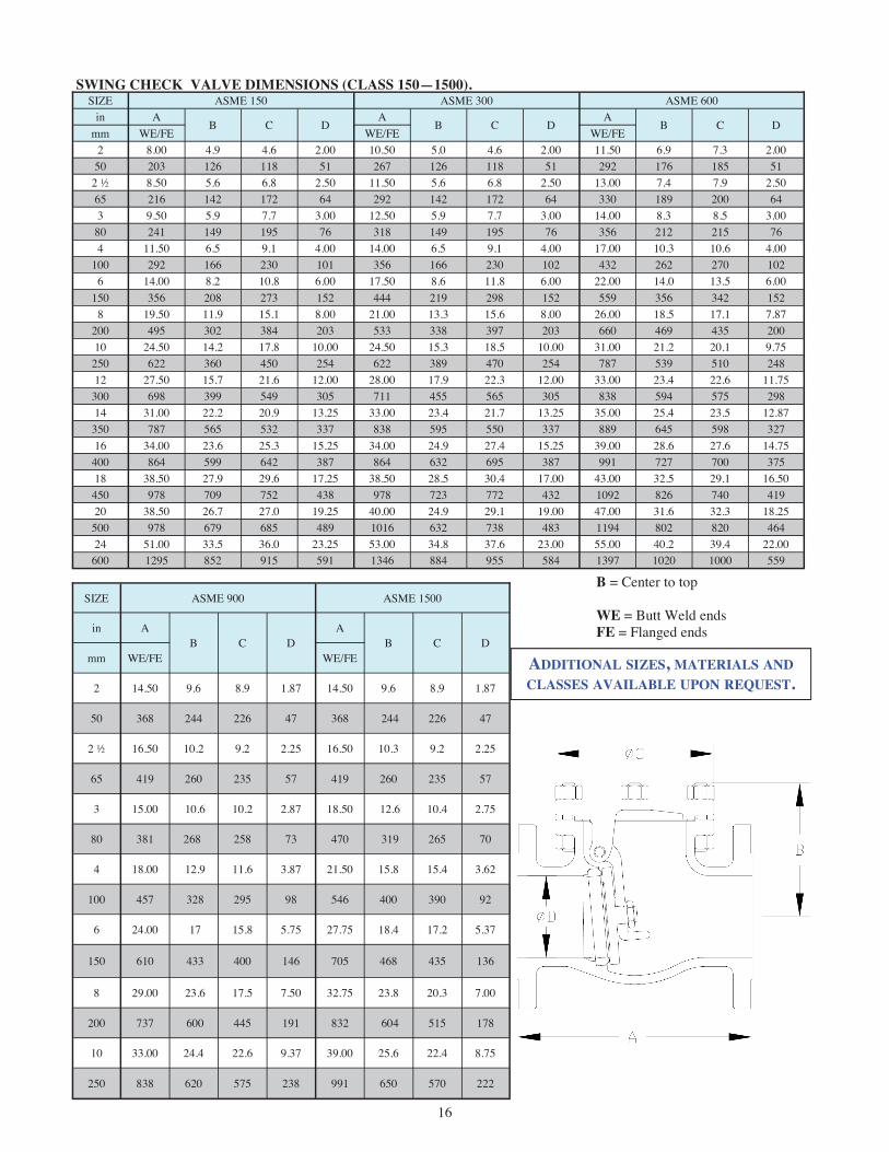
SWING CHECK VALVE DIMENSIONS (CLASS 150—1500).
B = Center to top WE = Butt Weld ends FE = Flanged ends
SIZE ASME 150 ASME 300 ASME 600 in A
B C D A
B C D A
B C D mm WE/FE WE/FE WE/FE
2 8.00 4.9 4.6 2.00 10.50 5.0 4.6 2.00 11.50 6.9 7.3 2.00 50 203 126 118 51 267 126 118 51 292 176 185 51
2 ½ 8.50 5.6 6.8 2.50 11.50 5.6 6.8 2.50 13.00 7.4 7.9 2.50 65 216 142 172 64 292 142 172 64 330 189 200 64 3 9.50 5.9 7.7 3.00 12.50 5.9 7.7 3.00 14.00 8.3 8.5 3.00
80 241 149 195 76 318 149 195 76 356 212 215 76 4 11.50 6.5 9.1 4.00 14.00 6.5 9.1 4.00 17.00 10.3 10.6 4.00
100 292 166 230 101 356 166 230 102 432 262 270 102 6 14.00 8.2 10.8 6.00 17.50 8.6 11.8 6.00 22.00 14.0 13.5 6.00
150 356 208 273 152 444 219 298 152 559 356 342 152 8 19.50 11.9 15.1 8.00 21.00 13.3 15.6 8.00 26.00 18.5 17.1 7.87
200 495 302 384 203 533 338 397 203 660 469 435 200 10 24.50 14.2 17.8 10.00 24.50 15.3 18.5 10.00 31.00 21.2 20.1 9.75
250 622 360 450 254 622 389 470 254 787 539 510 248 12 27.50 15.7 21.6 12.00 28.00 17.9 22.3 12.00 33.00 23.4 22.6 11.75
300 698 399 549 305 711 455 565 305 838 594 575 298 14 31.00 22.2 20.9 13.25 33.00 23.4 21.7 13.25 35.00 25.4 23.5 12.87
350 787 565 532 337 838 595 550 337 889 645 598 327 16 34.00 23.6 25.3 15.25 34.00 24.9 27.4 15.25 39.00 28.6 27.6 14.75
400 864 599 642 387 864 632 695 387 991 727 700 375 18 38.50 27.9 29.6 17.25 38.50 28.5 30.4 17.00 43.00 32.5 29.1 16.50
450 978 709 752 438 978 723 772 432 1092 826 740 419 20 38.50 26.7 27.0 19.25 40.00 24.9 29.1 19.00 47.00 31.6 32.3 18.25
500 978 679 685 489 1016 632 738 483 1194 802 820 464 24 51.00 33.5 36.0 23.25 53.00 34.8 37.6 23.00 55.00 40.2 39.4 22.00
600 1295 852 915 591 1346 884 955 584 1397 1020 1000 559
SIZE ASME 900 ASME 1500
in A B C D
A B C D
mm WE/FE WE/FE
2 14.50 9.6 8.9 1.87 14.50 9.6 8.9 1.87
50 368 244 226 47 368 244 226 47
2 ½ 16.50 10.2 9.2 2.25 16.50 10.3 9.2 2.25
65 419 260 235 57 419 260 235 57
3 15.00 10.6 10.2 2.87 18.50 12.6 10.4 2.75
80 381 268 258 73 470 319 265 70
4 18.00 12.9 11.6 3.87 21.50 15.8 15.4 3.62
100 457 328 295 98 546 400 390 92
6 24.00 17 15.8 5.75 27.75 18.4 17.2 5.37
150 610 433 400 146 705 468 435 136
8 29.00 23.6 17.5 7.50 32.75 23.8 20.3 7.00
200 737 600 445 191 832 604 515 178
10 33.00 24.4 22.6 9.37 39.00 25.6 22.4 8.75
250 838 620 575 238 991 650 570 222
ADDITIONAL SIZES, MATERIALS AND CLASSES AVAILABLE UPON REQUEST.

17
API 600 WALL SWING CHECK VALVES BOLTED BONNET, ASME CLASSES 150 TO 1500 CAST CARBON , STAINLESS STEEL OR ALLOY STEEL
F = Dismantling dimension WE = Butt Weld ends FE = Flanged ends WT = Weight CV = Flow coefficient
SIZE ASME 150 ASME 300 ASME 600 in
F in WT lb WT lb
CV F in WT lb WT lb
CV F in WT lb WT lb
CV
mm mm FE kg WE kg mm FE kg WE kg mm FE kg WE kg
2 6.0 27 23 75 6.0 34 29 75 8.0 62 49 75 50 155 12 10 155 15 13 205 28 22
2 ½ 7.0 40 35 120 7.0 53 45 120 8.5 79 62 120 65 175 18 16 175 24 21 220 36 28 3 7.5 53 41 170 7.5 68 58 170 10.0 110 79 170
80 190 24 19 190 31 27 250 50 36 4 8.5 79 57 320 8.5 110 94 320 12.5 215 168 320
100 215 36 26 220 50 42 315 98 76 6 11.0 132 113 760 11.5 212 182 760 17.0 439 335 760
150 285 60 51 295 96 82 435 199 152 8 16.0 337 293 1400 17.5 507 437 1400 22.5 811 633 1300
200 405 153 133 440 230 198 570 368 287 10 19.0 567 483 2200 20.5 858 728 2200 26.0 1343 1047 2100
250 490 257 219 515 389 330 665 609 475 12 22.0 873 758 3300 24.0 1160 1077 3300 29.5 1702 1363 3100
300 555 396 344 610 526 488 745 772 618 14 29.0 979 834 4000 30.0 1411 1241 4000 32.0 1958 1585 3700
350 735 444 378 765 640 563 810 888 719 16 31.0 1438 1250 5200 32.5 1764 1550 5200 36.0 2994 2364 4900
400 795 652 567 825 800 703 915 1358 1072 18 36.5 1927 1656 7000 37.0 2578 2192 6800 35.5 3449 2932 6400
450 930 874 751 940 1169 994 900 1564 1330 20 36.5 1771 1522 8700 34.5 2913 2505 8500 36.5 4792 4121 7800
500 925 803 690 875 1321 1136 925 2174 1869 24 45.0 3559 3062 13000 46.5 5204 4428 12000 45.0 7608 6467 11000
600 1150 1614 1388 1175 2360 2008 1145 3451 2933
SIZE ASME 900 ASME 1500
in F
in WT lb WT lb CV F
in WT lb WT lb CV
mm mm FE kg WE kg mm FE kg WE kg
2 10.5 165 132 65 10.5 165 132 65
50 270 75 60 270 75 60
2 ½ 11.5 265 183 100 11.5 265 183 100
65 290 120 83 290 120 83
3 12.0 209 154 160 14.0 375 271 150
80 305 95 70 355 170 123
4 15.0 375 271 300 17.5 963 463 260
100 380 170 123 445 437 210
6 20.0 716 518 700 21.0 1235 1036 600
150 505 325 235 535 560 470
8 27.5 1257 877 1200 27.5 2271 1907 1100
200 700 570 398 695 1030 865
10 29.0 1808 1437 1900 30.0 3483 2888 1700
250 740 820 652 760 1580 1310

18
API 600 WALL TILTING DISC CHECK VALVES BOLTED BONNET, ASME CLASSES 150 TO 1500 CAST CARBON OR ALLOY STEEL
Item Applicable Specification Wall thickness API 600
Pressure - temperature ratings ASME B16.34
General valve design ASME B16.34 End to End dimensions ASME B16.10
Flange design ASME B16.5 Butt Weld design ASME B16.25
Materials ASTM
Design Specifications
DESIGN FEATURES: • Standard trim is API trim 8 for carbon steel
valves, API trim 5 for chrome alloy valves, and API trim 10 for CF8M (T316) valves for optimal performance under normal condi-tions. Other trim materials available on re-quest.
• Seat face: Stellited, ground and lapped to a smooth finish.
• Body and cap joint accurately machined. • Flanges: Classes 150-300: 1/16” raised face. Class 600 and up: 1/4” raised face. Finish 125-250 AARH for all valves. • Check valves are suitable for service in hori-
zontal line with cap vertical or in a vertical line with flow upward.
Class Figure Number
150 1595
300 3095
600 6095
900 9095
1500 1395
(1) Side Plug Gasket Design
(2) Side Plug Packing Design
NOTE: See page 52 for flow, safety and maintenance information.
STANDARD MATERIALS (Other materials available) PART MATERIALS
Body A216 Gr. WCB A217 Gr. WC6 A217 Gr. WC9 Cap A216 Gr. WCB A217 Gr. WC6 A217 Gr. WC9
Disc A105 + 13% CR or
A216 WCB + 13% CR Faced
WC6 + Stellite 6 Faced
Seat Ring Carbon Steel + Stellite 6 Faced
A182 F11 + Stellite 6 Faced
A182 F22 + Stellite 6 Faced
Gasket Class 150: Corrugated SST Encapsulated w/ Graphite
Class 300 to 600: Spiral Wound SST w/ Graphite Class 900 to 1500: RTJ
Pin SST 410 Bushing SST 410
Pin Plug (1) SST 410 Pin Plug Gasket (1) Graphite coated SST
Body / Cap Stud A193 Gr. B7 A193 Gr. B16 Body / Cap Nut A194 Gr. 2H A194 Gr. 7
Gland Flange (2) A216 WCB Gland (2) SST 410
Packing (2) Graphite Gland Flange Stud (2) A193 Gr. B7 A193 Gr. B16
Gland Flange Nut (2) A194 Gr. 2H A194 Gr. 7
Identification Plate Series 300 SST
WC9 + Stellite 6 Faced
A217 WC6 A217 WC9

19
TILTING DISC CHECK VALVE DIMENSIONS (CLASS 150—600).
B = Center to top WE = Butt Weld ends FE = Flanged ends
SIZE ASME 150 ASME 300 ASME 600 in A
B C D A
B C D A
B C D mm WE/FE WE/FE WE/FE 2 ½ 8.50 6.3 7.1 2.50 11.50 7.5 8.1 2.50 13.00 9.5 8.0 2.50 65 216 160 180 64 292 190 205 64 330 242 203 64 3 9.50 6.8 7.7 3.00 12.50 9.1 6.7 3.00 14.00 9.9 8.9 3.00
80 241 172 195 76 318 231 170 76 356 252 225 76 4 11.50 7.6 8.9 4.00 14.00 10.6 9.5 4.00 17.00 10.6 9.7 4.00
100 292 193 225 102 356 268 240 102 432 269 245 102 6 14.00 10.9 11.0 6.00 17.50 12.8 11.6 6.00 22.00 12.8 12.9 6.00
150 356 277 280 152 444 325 295 152 559 324 328 152 8 19.50 12.7 14.4 8.00 21.00 15.5 14.8 8.00 26.00 15.1 15.8 7.88
200 495 324 365 203 533 394 375 203 660 384 402 200 10 24.50 13.2 19.9 10.00 24.50 17.4 18.3 10.00 31.00 19.3 19.5 9.75
250 622 336 506 254 622 442 465 254 787 490 495 248 12 27.50 18.6 20.3 12.00 28.00 20.3 21.5 12.00 33.00 21.1 21.6 11.75
300 698 472 515 305 711 516 545 305 838 537 549 298 14 31.00 19.1 22.1 13.25 33.00 20.6 22.8 13.25 35.00 23.7 24.4 12.88
350 787 485 560 337 838 524 578 337 889 602 620 327 16 34.00 21.6 25.0 15.25 34.00 22.4 26.2 15.25 39.00 26.5 27.2 14.75
400 864 548 635 387 864 570 665 387 991 673 690 375 18 38.50 24.3 28.0 17.25 38.50 28.1 28.7 17.00
450 978 617 710 438 978 713 730 432 20 38.50 26.1 29.5 19.25 40.00 35.0 31.9 19.00
500 978 674 750 489 1016 889 809 483 24 51.00 27.3 33.9 23.25 53.00 42.8 37.5 23.00
600 1295 694 860 591 1346 1082 953 584
ADDITIONAL SIZES, MATERIALS AND
CLASSES AVAILABLE UPON REQUEST.

20
API 600 TILTING DISC CHECK VALVES BOLTED BONNET, ASME CLASSES 150 TO 1500 CAST CARBON , STAINLESS STEEL OR ALLOY STEEL
FE = Flanged ends WE = Weld ends F = Dismantling dimension WT = Weight CV = Flow coefficient
SIZE ASME 150 ASME 300 ASME 600
in F
in WT lb WT lb CV F
in WT lb WT lb CV F
in WT lb WT lb CV
mm mm FE kg WE kg mm FE kg WE kg mm FE kg WE kg
2 ½ 9.0 20 17 150 10.0 35 30 150 12.0 40 34 150
65 225 9 8 255 16 14 305 18 15
3 10.0 29 25 200 12.0 46 40 200 13.0 51 43 200
80 250 13 11 305 21 18 330 23 20
4 11.5 49 42 360 14.5 58 50 360 14.5 75 65 360
100 295 22 19 370 26 23 370 34 29
6 17.0 92 80 790 19.0 138 120 790 19.0 185 159 790
150 430 42 36 475 63 54 475 84 72
8 20.5 161 140 1400 23.5 240 208 1400 23.0 335 289 1400
200 530 73 64 600 109 94 585 152 131
10 23.5 262 229 2100 27.5 385 334 2100 29.0 700 600 2100
250 590 119 104 695 175 152 740 318 272
12 30.5 380 330 3000 32.5 520 450 3000 33.0 774 672 3000
300 780 172 150 820 236 204 835 351 305
14 32.5 517 450 3700 34.0 750 650 3700 36.5 980 850 3500
350 825 235 204 860 340 295 930 445 386
16 37.0 713 620 4900 38.0 1050 900 4900 41.5 1300 1124 4600
400 935 323 281 960 476 408 1050 590 510
18 41.5 829 720 6200 45.0 1126 980 6200
450 1055 376 327 1145 511 445
20 45.5 938 815 7700 54.0 1422 1231 7700
500 1165 426 370 1375 645 558
24 50.5 1325 1152 11000 66.0 2004 1735 11000
600 1285 601 523 1670 909 787

21
ACCESSORIES GEAR ACTUATOR
Most Powell Multi-Turn Valves can be supplied with Adapto Gears. For installed Powell valves, gear units with adaptor parts are available. Adapto Gear units are also available separately for any Multi-Turn valve appli-cation.
Typical Adapto-Gear Installation: a. Remove the handwheel. b. Remove bolts from the yoke, mount the
adaptor, replace bolts and tighten. c. Install the sleeve and key on stem bushing. d. Mount gear operator on adaptor and bolt
together. e. Conversion is completed.
For installed valves, adaptors are provided so that new stem bushings or bonnets are not necessary. Field conversion can be completed without removing the valve from service.
Powell Adapto Gear Actuators are fully enclosed, light weight, maintenance free Bevel Gear units for valves which require gearing to facilitate operation. The actuators mount quickly and easily as installation does not require special complicated parts. The manual valve actuators, Type AA, B, and C, have been designed for simplicity, high efficiency and ease of adaptability to make them ideal for use on both small and large valves. The input shaft is mounted on antifriction bearings and the bevel gear drive sleeve is supported by an integral bearing arrangement. The actuator does not take any of the valve stem thrust since the thrust is absorbed in the valve stem bushing.
• Anti-friction bearings permits ease of operation. • Housing protects gears from dirt, dust, and other
foreign materials. Also good as a safety factor to protect operating personnel.
• Housing has provision for plug or pipe stem protector when required. Sealed housing retains the lubricant and protects the moving parts.
• Adaptors for air wrench operation can be supplied on order.
ADVANTAGES
MODEL AA-18 ACTUATOR
Max Torque: 996 ft-lb [1350 Nm] Gear Ratio: 2.92:1
MODEL B-24 ACTUATOR
Max Torque: 1990 ft-lb [2700 Nm] Gear Ratio: 4.07:1
MODEL C-24 ACTUATOR
Max Torque: 3980 ft-lb [5400 Nm] Gear Ratio: 6:1

22
ACCESSORIES cont... MOTOR ACTUATOR Most Powell Valves can be furnished with electric
motor actuators. This type of equipment gives fast, safe, efficient operation of any valve by means of a push button locally or from a remote point or automatically from a limit switch, pres-sure switch or other similar device.
To enable Powell to quote accurately on Motor Actuated Valves, please provide the following complete information:
A. Valve Size and Figure Number
B. Media
C. Media Pressure and Temperature
D. Differential Pressure against which the valve must open and close and Line Pres-sure if different from differential pressure.
E. Opening or Closing Time Requirements. Unless specified - gate valve stem speed is 12” per minute (approx.) and globe valve stem speed is 4” per minute (approx.).
F. Voltage, Frequency and Number of Phases
G. Special Features (e.g. control station re-quirements, special enclosure types, etc.)

23
ACCESSORIES cont... HYDRAULIC OR
PNEUMATIC ACTUATOR Most Powell Valves can be equipped with Hydraulic or Pneumatic Actuators for automatic or remote opening and closing.
When ordering such valves, please provide the following information:
A. Valve Size and Figure Number
B. Media
C. Media Pressure and Temperature
D. Differential Pressure against which the valve must open and close and Line Pressure if dif-ferent from differential pressure.
E. Opening or Closing Time Requirements
F. Actuator Media Pressure - Min./Max.
G. Failure Position (open, close, or as is)
H. Special Features (e.g. limit switches, manual override, etc.)
I. Environmental Temperature Range - Min./Max.

24
ACCESSORIES cont... LIMIT SWITCH
Powell Valves can be equipped with Limit Switches to signal users when the valve is in the fully open and fully closed position. This can help reduce extraneous wear caused by forcing the wedge or disc farther into the seat rings or back seat after the valve is already in the fully open or fully closed position. Limit Switches can also be used for fully automated valve operation in conjunction with motor, hydraulic, or pneu-matic actuators.
NOTE: The installation of a limit switch may require further machining or more parts added to the valve. Typical installation on handwheel operated valves.

25
ENGINEERING DATA INDEX
PAGE
VALVE STANDARDS AND RELATED INFORMATION 26
PRESSURE/TEMPERATURE RATINGS 27-34
CHEMICAL AND PHYSICAL PROPERTIES 35
TRIM DESCRIPTIONS 36
DIMENSIONS OF WROUGHT STEEL PIPE AND WELD END CONFIGURATIONS 37-42
STEEL VALVE FLANGE DIMENSIONS 43-49
METHOD OF DESIGNATING LOCATION OF AUXILIARY CONNECTIONS 50
BYPASS DIMENSIONS 51
FLOW DESIGN AND MAINTENANCE RECOMMENDATIONS 52
CONVERSION DATA AND EQUIVALENTS 53-54
NOTE: DATA PROVIDED IN THIS SECTION IS FOR REFERENCE PURPOSES AND IS SUBJECT TO CHANGE. CONSULT CURRENT STANDARDS AND SPECIFICATIONS FOR THE LATEST DATA AND FOR SPE-CIFIC DETAILS WHICH MAY BE BEYOND THE SCOPE OF THIS CATALOG.

26
VALVE STANDARDS AND RELATED INFORMATION
1. Steel and Corrosion Resistant Designs
(A) ASME B16.34 → Valves – Flanged, Threaded, and Welded End
This is the basic ASME valve standard for steel and corrosion resistant alloys. This standard contains re-quirements such as minimum shell wall thickness, pressure/temperature ratings, and pressure testing re-quirements.
(B) API Standard 600 → Steel Gate Valve Flanged and Butt Welded Ends, Bolted Bonnets
This is the basic API Gate valve standard and contains wall thicknesses that are heavier than ASME B16.34 for bolted bonnet steel and alloy steel valves. This standard refers to B16.34 for pressure/temperature rat-ings.
(C) API Standard 598 → Valve Inspection and Testing
This standard is referenced by both ASME B16.34 and API 600 and contains minimum inspection and pres-sure test requirements.
(D) ASME B16.10 → Face to Face and End to End Dimensions of Valves
(E) ASME B16.5 → Pipe Flanges and Flanged Fittings
(F) ASME B16.25 → Buttwelding Ends
(G) MSS SP-25 → Standard Marking System for Valves, Fittings, Flanges and Unions
(H) MSS SP-55 → Quality Standard for Steel Castings for Valves, Flanges, Fittings, and Other Piping Components
2. Powell Publications and Miscellaneous Information
The Handbook of Valve Information contains valve selection, storage, installation, operation, and maintenance infor-mation for all Powell Valves. NOTE: Prior to any installation or maintenance, appropriate precautions must be followed. For example, all pressure must be relieved from the valve and affected piping prior to servicing and proper protective clothing and equipment must be worn.

27
PRESSURE/TEMPERATURE RATINGS
TABLE 1
ASTM A216 Grade WCB
Upon prolonged exposure to temperatures above 800º F, the carbide phase of steel may be converted to graphite. Permissible, but not recommended for prolonged use above 800º F.
STANDARD CLASS Working Pressures by Classes, psig
Temperature. ºF 150 300 600 900 1500 2500 4500 -20 to 100 285 740 1,480 2,220 3,705 6,170 11,110
200 260 680 1,360 2,035 3,395 5,655 10,185 300 230 655 1,310 1,965 3,270 5,450 9,815 400 200 635 1,265 1,900 3,170 5,280 9,505 500 170 605 1,205 1,810 3,015 5,025 9,040 600 140 570 1,135 1,705 2,840 4,730 8,515 650 125 550 1,100 1,650 2,745 4,575 8,240 700 110 530 1,060 1,590 2,665 4,425 7,960 750 95 505 1,015 1,520 2,535 4,230 7,610 800 80 410 825 1,235 2,055 3,430 6,170
Working Pressures by Classes, psig Temperature. ºF 150 300 600 900 1500 2500 4500
-20 to 100 290 750 1,500 2,250 3,750 6,250 11,250 200 290 750 1,500 2,250 3,750 6,250 11,250 300 285 740 1,480 2,220 3,700 6,170 11,105 400 280 735 1,465 2,200 3,665 6,105 10,995 500 280 735 1,465 2,200 3,665 6,105 10,995 600 280 735 1,465 2,200 3,665 6,105 10,995 650 275 715 1,430 2,145 3,575 5,960 10,730 700 265 690 1,380 2,075 3,455 5,760 10,365 750 245 635 1,270 1,905 3,170 5,285 9,515 800 195 515 1,030 1,545 2,570 4,285 7,715
SPECIAL CLASS
NOTE: Special Class Ratings apply to Threaded and Weld End Valves only and require upgrading per paragraph 8 of ASME B16.34
28
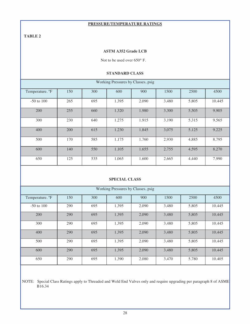
PRESSURE/TEMPERATURE RATINGS
TABLE 2
ASTM A352 Grade LCB
Not to be used over 650° F.
STANDARD CLASS
Working Pressures by Classes, psig
Temperature. ºF 150 300 600 900 1500 2500 4500
-50 to 100 265 695 1,395 2,090 3,480 5,805 10,445
200 255 660 1,320 1,980 3,300 5,505 9,905
300 230 640 1,275 1,915 3,190 5,315 9,565
400 200 615 1,230 1,845 3,075 5,125 9,225
500 170 585 1,175 1,760 2,930 4,885 8,795
600 140 550 1,105 1,655 2,755 4,595 8,270
650 125 535 1,065 1,600 2,665 4,440 7,990
Working Pressures by Classes, psig
Temperature. ºF 150 300 600 900 1500 2500 4500
-50 to 100 290 695 1,395 2,090 3,480 5,805 10,445
200 290 695 1,395 2,090 3,480 5,805 10,445
300 290 695 1,395 2,090 3,480 5,805 10,445
400 290 695 1,395 2,090 3,480 5,805 10,445
500 290 695 1,395 2,090 3,480 5,805 10,445
600 290 695 1,395 2,090 3,480 5,805 10,445
650 290 695 1,390 2,080 3,470 5,780 10,405
SPECIAL CLASS
NOTE: Special Class Ratings apply to Threaded and Weld End Valves only and require upgrading per paragraph 8 of ASME B16.34

29
PRESSURE/TEMPERATURE RATINGS
TABLE 3
ASTM A217 Grade WC6
Use normalized and tempered material only. Not to be used over 1100º F.
STANDARD CLASS
Working Pressures by Classes, psig Temperature. ºF 150 300 600 900 1500 2500 4500
-20 to 100 290 750 1,500 2,250 3,750 6,250 11,250 200 260 750 1,500 2,250 3,750 6,250 11,250 300 230 720 1,445 2,165 3,610 6,015 10,830 400 200 695 1,385 2,080 3,465 5,775 10,400 500 170 665 1,330 1,995 3,325 5,540 9,965 600 140 605 1,210 1,815 3,025 5,040 9,070 650 125 590 1,175 1,765 2,940 4,905 8,825 700 110 570 1,135 1,705 2,840 4,730 8,515 750 95 530 1,065 1,595 2,660 4,430 7,970 800 80 510 1,015 1,525 2,540 4,230 7,610 850 65 485 975 1,460 2,435 4,060 7,305 900 50 450 900 1,350 2,245 3,745 6,740 950 35 320 640 955 1,595 2,655 4,785
1000 20 215 430 650 1,080 1,800 3,240 1050 20(1) 145 290 430 720 1,200 2,160 1100 20(1) 95 190 290 480 800 1,440
NOTE: (1) For welding end valves only. Flanged end ratings terminate at 1000º F.
SPECIAL CLASS
Working Pressures by Classes, psig Temperature. ºF 150 300 600 900 1500 2500 4500
-20 to 100 290 750 1,500 2,250 3,750 6,250 11,250 200 290 750 1,500 2,250 3,750 6,250 11,250 300 290 750 1,500 2,250 3,750 6,250 11,250 400 290 750 1,500 2,250 3,750 6,250 11,250 500 290 750 1,500 2,250 3,750 6,250 11,250 600 290 750 1,500 2,250 3,750 6,250 11,250 650 290 750 1,500 2,250 3,750 6,250 11,250 700 280 735 1,465 2,200 3,665 6,110 10,995 750 280 730 1,460 2,185 3,645 6,070 10,930 800 275 720 1,440 2,160 3,600 6,000 10,800 850 260 680 1,355 2,030 3,385 5,645 10,160 900 225 585 1,175 1,760 2,935 4,895 8,805 950 155 400 795 1,195 1,995 3,320 5,980
1000 105 270 540 810 1,350 2,250 4,050 1050 70 180 360 540 900 1,500 2,700 1100 45 120 240 360 600 1,000 1,800
NOTE: Special Class Ratings apply to Threaded and Weld End Valves only and require upgrading per paragraph 8 of ASME B16.34

30
PRESSURE/TEMPERATURE RATINGS
TABLE 4
ASTM A217 Grade WC9
Use normalized and tempered material only. Not to be used over 1100º F.
STANDARD CLASS
Working Pressures by Classes, psig Temperature. ºF 150 300 600 900 1500 2500 4500
-20 to 100 290 750 1,500 2,250 3,750 6,250 11,250 200 260 750 1,500 2,250 3,750 6,250 11,250 300 230 730 1,455 2,185 3,640 6,070 10,925 400 200 705 1,410 2,115 3,530 5,880 10,585 500 170 665 1,330 1,995 3,325 5,540 9,965 600 140 605 1,210 1,815 3,025 5,040 9,070 650 125 590 1,175 1,765 2,940 4,905 8,825 700 110 570 1,135 1,705 2,840 4,730 8,515 750 95 530 1,065 1,595 2,660 4,430 7,970 800 80 510 1,015 1,525 2,540 4,230 7,610 850 65 485 975 1,460 2,435 4,060 7,305 900 50 450 900 1,350 2,245 3,745 6,740 950 35 385 755 1,160 1,930 3,220 5,795
1000 20 265 535 800 1,335 2,230 4,010 1050 20(1) 175 350 525 875 1,455 2,625 1100 20(1) 110 220 330 550 915 1,645
NOTE: (1) For welding end valves only. Flanged end ratings terminate at 1000º F.
SPECIAL CLASS
Working Pressures by Classes, psig Temperature. ºF 150 300 600 900 1500 2500 4500
-20 to 100 290 750 1,500 2,250 3,750 6,250 11,250 200 290 750 1,500 2,250 3,750 6,250 11,250 300 285 740 1,480 2,220 3,695 6,160 11,090 400 280 730 1,455 2,185 3,640 6,065 10,915 500 280 725 1,450 2,175 3,620 6,035 10,865 600 275 720 1,440 2,165 3,605 6,010 10,815 650 275 715 1,430 2,145 3,580 5,965 10,735 700 270 705 1,415 2,120 3,535 5,895 10,605 750 270 705 1,415 2,120 3,535 5,895 10,605 800 270 705 1,415 2,120 3,535 5,895 10,605 850 260 680 1,355 2,030 3,385 5,645 10,160 900 230 600 1,200 1,800 3,000 5,000 9,000 950 180 470 945 1,415 2,360 3,930 7,070
1000 130 335 670 1,005 1,670 2,785 5,015 1050 85 220 435 655 1,095 1,820 3,280 1100 55 135 275 410 685 1,145 2,055
NOTE: Special Class Ratings apply to Threaded and Weld End Valves only and require upgrading per paragraph 8 of ASME B16.34

31
PRESSURE/TEMPERATURE RATINGS
TABLE 5
ASTM A217 Grade C5 Use normalized and tempered material only.
STANDARD CLASS
NOTE: (1) For welding end valves only. Flanged end ratings terminate at 1000º F.
SPECIAL CLASS
NOTE: Special Class Ratings apply to Threaded and Weld End Valves only and require upgrading per paragraph 8 of ASME B16.34
Working Pressures by Classes, psig Temperature ºF 150 300 600 900 1500 2500 4500
-20 to 100 290 750 1,500 2,250 3,750 6,250 11,250 200 260 750 1,500 2,250 3,750 6,250 11,250 300 230 730 1,455 2,185 3,640 6,070 10,925 400 200 705 1,410 2,115 3,530 5,880 10,585 500 170 665 1,330 1,995 3,325 5,540 9,965 600 140 605 1,210 1,815 3,025 5,040 9,070 650 125 590 1,175 1,765 2,940 4,905 8,825 700 110 570 1,135 1,705 2,840 4,730 8,515 750 95 530 1,065 1,595 2,660 4,430 7,970 800 80 510 1,015 1,525 2,540 4,230 7,610 850 65 485 975 1,460 2,435 4,060 7,305 900 50 375 745 1,120 1,870 3,115 5,605 950 35 275 550 825 1,370 2,285 4,115
1000 20 200 400 595 995 1,655 2,985 1050 20(1) 145 290 430 720 1,200 2,160 1100 20(1) 100 200 300 495 830 1,490 1150 20(1) 60 125 185 310 515 925 1200 15(1) 35 70 105 170 285 515
Working Pressures by Classes, psig Temperature ºF 150 300 600 900 1500 2500 4500
-20 to 100 290 750 1,500 2,250 3,750 6,250 11,250 200 290 750 1,500 2,250 3,750 6,250 11,250 300 290 750 1,500 2,250 3,750 6,250 11,250 400 290 750 1,500 2,250 3,750 6,250 11,250 500 290 750 1,500 2,250 3,750 6,250 11,250 600 290 750 1,500 2,250 3,750 6,250 11,250 650 290 750 1,500 2,250 3,750 6,250 11,250 700 280 735 1,465 2,200 3,665 6,110 10,995 750 280 730 1,460 2,185 3,645 6,070 10,930 800 275 720 1,440 2,160 3,600 6,000 10,800 850 260 615 1,225 1,840 3,065 5,105 9,195 900 230 465 935 1,400 2,335 3,895 7,005 950 170 345 685 1,030 1,715 2,855 5,145
1000 125 250 495 745 1,245 2,070 3,730 1050 90 180 360 540 900 1,500 2,700 1100 60 125 250 375 620 1,035 1,865 1150 40 75 155 230 385 645 1,155 1200 20 45 85 130 215 355 645

32
PRESSURE/TEMPERATURE RATINGS
TABLE 6
ASTM A217 Grade C12 Use normalized and tempered material only.
STANDARD CLASS
NOTE: (1) For welding end valves only. Flanged end ratings terminate at 1000º F.
SPECIAL CLASS
NOTE: Special Class Ratings apply to Threaded and Weld End Valves only and require upgrading per paragraph 8 of ASME B16.34
Working Pressures by Classes, psig Temperature ºF 150 300 600 900 1500 2500 4500
-20 to 100 290 750 1,500 2,250 3,750 6,250 11,250 200 260 750 1,500 2,250 3,750 6,250 11,250 300 230 730 1,455 2,185 3,640 6,070 10,925 400 200 705 1,410 2,115 3,530 5,880 10,585 500 170 665 1,330 1,995 3,325 5,540 9,965 600 140 605 1,210 1,815 3,025 5,040 9,070 650 125 590 1,175 1,765 2,940 4,905 8,825 700 110 570 1,135 1,705 2,840 4,730 8,515 750 95 530 1,065 1,595 2,660 4,430 7,970 800 80 510 1,015 1,525 2,540 4,230 7,610 850 65 485 975 1,460 2,435 4,060 7,305 900 50 450 900 1,350 2,245 3,745 6,740 950 35 375 755 1,130 1,885 3,145 5,655
1000 20 255 505 760 1,270 2,115 3,805 1050 20(1) 170 345 515 855 1,430 2,570 1100 20(1) 115 225 340 565 945 1,695 1150 20(1) 75 150 225 375 630 1,130 1200 20(1) 50 105 155 255 430 770
Working Pressures by Classes, psig Temperature ºF 150 300 600 900 1500 2500 4500
-20 to 100 290 750 1,500 2,250 3,750 6,250 11,250 200 290 750 1,500 2,250 3,750 6,250 11,250 300 290 750 1,500 2,250 3,750 6,250 11,250 400 290 750 1,500 2,250 3,750 6,250 11,250 500 290 750 1,500 2,250 3,750 6,250 11,250 600 290 750 1,500 2,250 3,750 6,250 11,250 650 290 750 1,500 2,250 3,750 6,250 11,250 700 280 735 1,465 2,200 3,665 6,110 10,995 750 280 730 1,460 2,185 3,645 6,070 10,930 800 275 720 1,440 2,160 3,600 6,000 10,800 850 260 680 1,355 2,030 3,385 5,645 10,160 900 230 600 1,200 1,800 3,000 5,000 9,000 950 180 470 945 1,415 2,355 3,930 7,070
1000 120 315 635 950 1,585 2,645 4,755 1050 80 215 430 645 1,070 1,785 3,215 1100 55 140 285 425 705 1,180 2,120 1150 35 95 190 285 470 785 1,415 1200 25 65 130 195 320 535 965

33
PRESSURE/TEMPERATURE RATINGS
TABLE 7
ASTM A217 Grade C12A
STANDARD CLASS
NOTE: (1) For welding end valves only. Flanged end ratings terminate at 1000º F.
SPECIAL CLASS
NOTE: Special Class Ratings apply to Threaded and Weld End Valves only and require upgrading per paragraph 8 of ASME B16.34
Working Pressures by Classes, psig Temperature ºF 150 300 600 900 1500 2500 4500
-20 to 100 290 750 1,500 2,250 3,750 6,250 11,250 200 260 750 1,500 2,250 3,750 6,250 11,250 300 230 730 1,455 2,185 3,640 6,070 10,925 400 200 705 1,410 2,115 3,530 5,880 10,585 500 170 665 1,330 1,995 3,325 5,540 9,965 600 140 605 1,210 1,815 3,025 5,040 9,070 650 125 590 1,175 1,765 2,940 4,905 8,825 700 110 570 1,135 1,705 2,840 4,730 8,515 750 95 530 1,065 1,595 2,660 4,430 7,970 800 80 510 1,015 1,525 2,540 4,230 7,610 850 65 485 975 1,460 2,435 4,060 7,305 900 50 450 900 1,350 2,245 3,745 6,740 950 35 385 775 1,160 1,930 3,220 5,795
1000 20 365 725 1090 1,820 3,030 5,450 1050 20(1) 360 720 1080 1,800 3,000 5,400 1100 20(1) 300 605 905 1,510 2,515 4,525 1150 20(1) 225 445 670 1,115 1,855 3,345 1200 20(1) 145 290 430 720 1,200 2,160
Working Pressures by Classes, psig Temperature ºF 150 300 600 900 1500 2500 4500
-20 to 100 290 750 1,500 2,250 3,750 6,250 11,250 200 290 750 1,500 2,250 3,750 6,250 11,250 300 290 750 1,500 2,250 3,750 6,250 11,250 400 290 750 1,500 2,250 3,750 6,250 11,250 500 290 750 1,500 2,250 3,750 6,250 11,250 600 290 750 1,500 2,250 3,750 6,250 11,250 650 290 750 1,500 2,250 3,750 6,250 11,250 700 280 735 1,465 2,200 3,665 6,110 10,995 750 280 730 1,460 2,185 3,645 6,070 10,930 800 275 720 1,440 2,160 3,600 6,000 10,800 850 260 680 1,355 2,030 3,385 5,645 10,160 900 230 600 1,200 1,800 3,000 5,000 9,000 950 180 470 945 1,415 2,360 3,930 7,070
1000 160 420 840 1,260 2,105 3,505 6,310 1050 160 420 840 1,260 2,105 3,505 6,310 1100 145 375 755 1,130 1,885 3,145 5,655 1150 105 280 555 835 1,395 2,320 4,180 1200 70 180 360 540 900 1,500 2,700

34
PRESSURE/TEMPERATURE RATINGS
TABLE 8
STANDARD CLASS
SPECIAL CLASS
ASTM A351 Grade CF3M (a) ASTM A351 Grade CF8M (b)
(a) Not to be used over 850° F. (b) At temperatures over 1000º F, use only when the carbon content is 0.04% or higher. This requirement must be specified
by customer when applicable.
NOTE: (1) For Cryogenic Valves, -20° F rating extends to -423° F. (2) For welded end valves only. Flanged end ratings terminate at 1000° F.
NOTE: Special Class Ratings apply to Threaded and Weld End Valves only and require upgrading per paragraph 8 of ASME B16.34
Working Pressures by Classes, psig Temperature, ºF 150 300 600 900 1500 2500 4500 -20 to 100 (1) 275 720 1,440 2,160 3,600 6,000 10,800
200 235 620 1,240 1,860 3,095 5,160 9,290 300 215 560 1,120 1,680 2,795 4,660 8,390 400 195 515 1,025 1,540 2,570 4,280 7,705 500 170 480 955 1,435 2,390 3,980 7,165 600 140 450 900 1,355 2,255 3,760 6,770 650 125 440 885 1,325 2,210 3,680 6,625 700 110 435 870 1,305 2,170 3,620 6,515 750 95 425 855 1,280 2,135 3,560 6,410 800 80 420 845 1,265 2,110 3,520 6,335 850 65 420 835 1,255 2,090 3,480 6,265 900 50 415 830 1,245 2,075 3,460 6,230 950 35 385 775 1,160 1,930 3,220 5,795
1000 20 365 725 1,090 1,820 3,030 5,450 1050 20(2) 360 720 1,080 1,800 3,000 5,400 1100 20(2) 305 610 915 1,525 2,545 4,575 1150 20(2) 235 475 710 1,185 1,970 3,550 1200 20(2) 185 370 555 925 1,545 2,775 1250 20(2) 145 295 440 735 1,230 2,210 1300 20(2) 115 235 350 585 970 1,750 1350 20(2) 95 190 290 480 800 1,440 1400 20(2) 75 150 225 380 630 1,130 1450 20(2) 60 115 175 290 485 875 1500 15(2) 40 85 125 205 345 620
Working Pressures by Classes, psig Temperature, ºF 150 300 600 900 1500 2500 4500 -20 to 100 (1) 290 750 1,500 2,250 3,750 6,250 11,250
200 265 690 1,380 2,075 3,455 5,760 10,365 300 240 625 1,250 1,870 3,120 5,200 9,360 400 220 575 1,145 1,720 2,865 4,775 8,600 500 205 535 1,065 1,600 2,665 4,440 7,995 600 195 505 1,005 1,510 2,520 4,195 7,555 650 190 495 985 1,480 2,465 4,105 7,395 700 185 485 970 1,455 2,425 4,040 7,270 750 185 475 955 1,430 2,385 3,975 7,150 800 180 470 945 1,415 2,355 3,930 7,070 850 180 465 930 1,400 2,330 3,885 6,990 900 180 465 925 1,390 2,315 3,860 6,950 950 175 460 915 1,375 2,290 3,815 6,870 1000 160 420 840 1,260 2,105 3,505 6,310 1050 160 420 840 1,260 2,105 3,505 6,310 1100 145 380 765 1,145 1,905 3,180 5,720 1150 115 295 590 885 1,480 2,465 4,435 1200 90 230 465 695 1,155 1,930 3,470 1250 70 185 370 555 920 1,535 2,765 1300 55 145 290 435 730 1,215 2,185 1350 45 120 240 360 600 1,000 1,800 1400 35 95 190 285 470 785 1,415 1450 30 75 145 220 365 605 1,095 1500 20 50 105 155 260 430 770

35
CHEMICAL AND PHYSICAL PROPERTIES CAST CARBON, ALLOY STEELS, AND STAINLESS STEEL
TABLE 9
*RESIDUAL ELEMENTS-Total must not exceed 1.00 maximum. **NITROGEN range is 0.030 to 0.070; ALUMINUM is 0.02 Max; TITANIUM is 0.01 max. ***The maximum MANGANESE may increase 0.04%, up to 1.28% maximum, for each reduction of 0.01% below the specified maximum CARBON content. ˟Impact tests required at –50° F. Minimum 13 ft-lb for two specimens and average of three. Minimum single specimen is 10 ft-lbs Ŧ For temperatures over 1000° F, minimum CARBON is 0.04. Customer must specify if temperature is over 1000° F and this minimum CARBON is required. NOTE: Chemical Compositions Are In Units Of Percent.
ASTM STANDARD GRADE A216 WCB
A217 WC6
A217 WC9
A217 C12
A217 C12A**
A352 LCB˟
A351 CF3M (316L)
A351 CF8M (316)
CARBON (C) (Min) - 0.05 0.05 - - 0.08 - - - (Max) 0.30 0.20 0.18 0.20 0.20 0.12 0.30 0.03 0.08
MANGANESE (Mn)
(Min) - 0.50 0.40 0.40 0.35 0.30 - - - (Max) 1.00*** 0.80 0.70 0.70 0.65 0.60 1.00*** 1.50 1.50
PHOSPHOROUS (P)
(Min) - - - - - - - - - (Max) 0.04 0.04 0.04 0.04 0.04 0.030 0.04 0.040 0.040
SULFUR (S) (Min) - - - - - - - - - (Max) 0.045 0.045 0.045 0.045 0.045 0.010 0.045 0.040 0.040
SILICON (Si) (Min) - - - - - 0.20 - - - (Max) 0.60 0.60 0.60 0.75 1.00 0.50 0.60 1.50 1.50
COPPER (Cu) (Min) - - - - - - - - - (Max) 0.30* 0.50* 0.50* 0.50* 0.50* - 0.30* - -
NICKEL (Ni) (Min) - - - - - - - 9.0 9.0 (Max) 0.50* 0.50* 0.50* 0.50* 0.50* 0.40 0.50* 13.0 12.0
CHROMIUM (Cr) (Min) - 1.00 2.00 4.00 8.00 8.0 - 17.0 18.0 (Max) 0.50* 1.50 2.75 6.50 10.00 9.5 0.50* 21.0 21.0
MOLYBDENUM (Mo)
(Min) - 0.45 0.90 0.45 0.90 0.85 - 2.0 2.0 (Max) 0.20* 0.65 1.20 0.65 1.20 1.05 0.20* 3.0 3.0
VANADIUM (V) (Min) - - - - - 0.18 - - - (Max) 0.03* - - - 0.06 0.25 0.03* - -
TUNGSTEN (W) (Min) - - - - - - - - - (Max) - 0.10* 0.10* 0.10* 0.10* - - - -
COLUMBIUM (Cb)
(Min) - - - - - 0.060 - - - (Max) - - - - 0.03 0.10 - - -
TENSILE STRENGTH
(Min) 70 Ksi 70 Ksi 70 Ksi 90 Ksi 90 85 Ksi 65 Ksi 70 Ksi 70 Ksi (Max) 95 95 95 115 115 110 90
YIELD STRENGTH
(Min) 36 Ksi 40 Ksi 40 Ksi 60 Ksi 60 Ksi 60 Ksi 35 Ksi 30 Ksi 30 Ksi
ELONGATION (Min) 22% 20% 20% 18% 18% 18% 24% 30% 30%
REDUCTION OF (Min) 35% 35% 35% 35% 35% 45% 35% - -
TEMPERATURE (Min) -20F -20F -20F -20F -20F -20F -50F -425F -425F (Max) 800F 1100F 1100F 1200F 1200F 1200F 650F 850F 1500FŦ
A217 C5

36
TRIM DESCRIPTIONS
TABLE 10
(a) Minimum 50HB differential hardness between mating seating surfaces (b) Stellite 6 ™ or equal.
API Trim No. Powell Trim Designation
Seat Nominal Description
Seat Nominal Composition
Nominal Hardness (HB)
Typical Stem/Backseat Material
1 1 F6 13 Cr 250 min (a) TYPE 410 or 420 (13Cr)
2 E 304 18Cr-8Ni - TYPE 304 (18Cr-8Ni)
5 5 Hardfaced Co-CrA (b) 350 TYPE 410 or 420 (13 Cr)
8 8 F6 and 13 Cr. 250 TYPE 410 or 420 (13 Cr)
Hardfaced Co-CrA (b) 350 9 9 Monel Ni-Cu Alloy - Monel (Ni-Cu)
10 0 316 18 Cr-8Ni-Mo - TYPE 316 (18Cr-8Ni-Mo)
11 D Monel and Ni-Cu Alloy - Monel (Ni-Cu) Hardfaced Co-CrA (b) 350
12 2 316 And 18Cr-8Ni-Mo - TYPE 316 (18Cr-8Ni-Mo)
Hardfaced Co-CrA (b) 350
13 3 Alloy 20 19Cr-29Ni - Alloy 20 (19Cr-29Ni)
14 4 Alloy 20 and 19Cr-29Ni - Alloy 20 (19Cr-29Ni)
Hardfaced Co-CrA (b) 350
15 U Hardfaced Co-CrA (b) 350 TYPE 304 (18Cr-8Ni)
16 6 Hardfaced Co-CrA (b) 350 TYPE 316 (18Cr-8Ni-Mo)
17 7 Hardfaced Co-CrA (b) 350 TYPE 347 (18Cr-10Ni-Cb)
18 J Hardfaced Co-CrA (b) 350 Alloy 20 (19Cr-29Ni)
Integral ½HF A Equal to Body Equal to Body -
Equal to Body Hardfaced Co-CrA (b) -
Integral Full HF B Hardfaced Co-CrA (b) - Equal to Body Integral C Equal to Body Equal to Body - Equal to Body
37
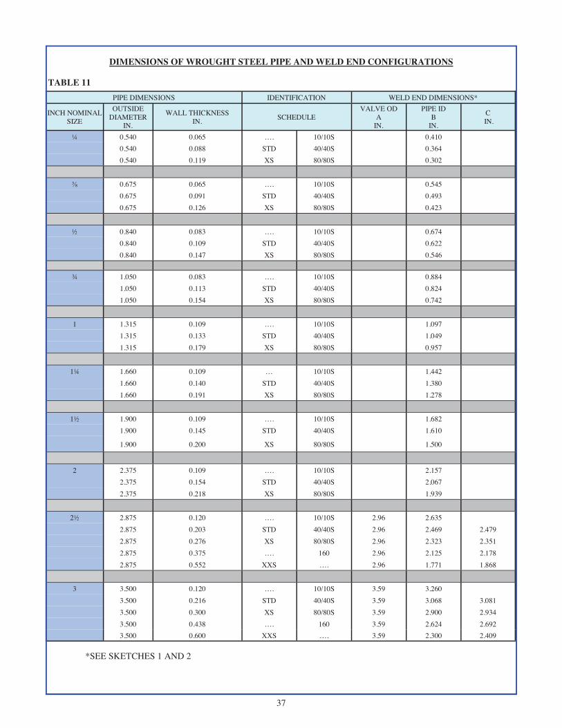
DIMENSIONS OF WROUGHT STEEL PIPE AND WELD END CONFIGURATIONS
TABLE 11 PIPE DIMENSIONS IDENTIFICATION WELD END DIMENSIONS*
INCH NOMINAL SIZE
OUTSIDE DIAMETER
IN.
WALL THICKNESS IN. SCHEDULE
VALVE OD A
IN.
PIPE ID B
IN. ¼ 0.540 0.065 …. 10/10S 0.410 0.540 0.088 STD 40/40S 0.364 0.540 0.119 XS 80/80S 0.302 ⅜ 0.675 0.065 …. 10/10S 0.545 0.675 0.091 STD 40/40S 0.493 0.675 0.126 XS 80/80S 0.423 ½ 0.840 0.083 …. 10/10S 0.674 0.840 0.109 STD 40/40S 0.622 0.840 0.147 XS 80/80S 0.546 ¾ 1.050 0.083 …. 10/10S 0.884 1.050 0.113 STD 40/40S 0.824 1.050 0.154 XS 80/80S 0.742 1 1.315 0.109 …. 10/10S 1.097 1.315 0.133 STD 40/40S 1.049 1.315 0.179 XS 80/80S 0.957
1¼ 1.660 0.109 … 10/10S 1.442 1.660 0.140 STD 40/40S 1.380 1.660 0.191 XS 80/80S 1.278
1½ 1.900 0.109 …. 10/10S 1.682 1.900 0.145 STD 40/40S 1.610
1.900 0.200 XS 80/80S 1.500
2 2.375 0.109 …. 10/10S 2.157 2.375 0.154 STD 40/40S 2.067 2.375 0.218 XS 80/80S 1.939
2½ 2.875 0.120 …. 10/10S 2.96 2.635 2.875 0.203 STD 40/40S 2.96 2.469 2.479 2.875 0.276 XS 80/80S 2.96 2.323 2.351 2.875 0.375 …. 160 2.96 2.125 2.178 2.875 0.552 XXS …. 2.96 1.771 1.868 3 3.500 0.120 …. 10/10S 3.59 3.260 3.500 0.216 STD 40/40S 3.59 3.068 3.081 3.500 0.300 XS 80/80S 3.59 2.900 2.934 3.500 0.438 …. 160 3.59 2.624 2.692 3.500 0.600 XXS …. 3.59 2.300 2.409
C IN.
*SEE SKETCHES 1 AND 2

38
DIMENSIONS OF WROUGHT STEEL PIPE AND WELD END CONFIGURATIONS
TABLE 11 (cont.)
PIPE DIMENSIONS IDENTIFICATION WELD END DIMENSIONS* INCH NOMINAL
SIZE OUTSIDE
DIAMETER IN.
WALL THICKNESS IN.
SCHEDULE VALVE OD A
IN.
PIPE ID B
IN. 4 4.500 0.120 …. 10/10S 4.62 4.260 4.500 0.237 STD 40/40S 4.62 4.026 4.044 4.500 0.337 XS 80/80S 4.62 3.826 3.869 4.500 0.438 …. 120 4.62 3.624 3.692 4.500 0.531 …. 160 4.62 3.438 3.530 4.500 0.674 XXS …. 4.62 3.152 3.279 6 6.625 0.134 …. 10/10S 6.78 6.357 6.625 0.280 STD 40/40S 6.78 6.065 6.094 6.625 0.432 XS 80/80S 6.78 5.761 5.828 6.625 0.562 …. 120 6.78 5.501 5.600 6.625 0.719 …. 160 6.78 5.187 5.326 6.625 0.864 XXS …. 6.78 4.897 5.072 8 8.625 0.148 …. 10/10S 8.78 8.329 8.625 0.250 …. 20 8.78 8.125 8.146 8.625 0.322 STD 40/40S 8.78 7.981 8.020 8.625 0.406 …. 60 8.78 7.813 7.873 8.625 0.500 XS 80/80S 8.78 7.625 7.709 8.625 0.594 …. 100 8.78 7.437 7.544 8.625 0.719 …. 120 8.78 7.187 7.326 8.625 0.812 …. 140 8.78 7.001 7.163 8.625 0.875 XXS …. 8.78 6.875 7.053 8.625 0.906 …. 160 8.78 6.813 6.998
10 10.750 0.165 …. 10/10S 10.94 10.420 10.750 0.250 …. 20/20S 10.94 10.250 10.272 10.750 0.365 STD 40/40S 10.94 10.020 10.070 10.750 0.500 XS 60/80S 10.94 9.750 9.834 10.750 0.594 …. 80 10.94 9.562 9.670 10.750 0.719 …. 100 10.94 9.312 9.451 10.750 0.844 …. 120 10.94 9.062 9.232 10.750 1.000 XXS 140 10.94 8.750 8.959 10.750 1.125 …. 160 10.94 8.500 8.740
12 12.750 0.180 …. 10/10S 12.97 12.390 12.750 0.250 …. 20 12.97 12.250 12.272 12.750 0.375 STD 40S 12.97 12.000 12.053 12.750 0.406 …. 40 12.97 11.938 11.999 12.750 0.500 XS 80S 12.97 11.750 11.834 12.750 0.562 …. 60 12.97 11.626 11.725 12.750 0.688 …. 80 12.97 11.374 11.505 12.750 0.844 …. 100 12.97 11.062 11.232 12.750 1.000 XXS 120 12.97 10.750 10.959 12.750 1.125 …. 140 12.97 10.500 10.740
C IN.
12.750 1.312 …. 160 12.97 10.126 10.413
*SEE SKETCHES 1 AND 2

39
DIMENSIONS OF WROUGHT STEEL PIPE AND WELD END CONFIGURATIONS
TABLE 11 (cont.)
*SEE SKETCHES 1 AND 2
PIPE DIMENSIONS IDENTIFICATION WELD END DIMENSIONS* INCH NOMINAL
SIZE OUTSIDE
DIAMETER IN.
WALL THICKNESS IN.
SCHEDULE VALVE OD A
IN.
PIPE ID B
IN.
C IN.
14 14 0.188 …. 10S 14.25 13.624
14 0.250 …. 10 14.25 13.500 14 0.312 …. 20 14.25 13.376 13.413 14 0.375 STD 30 14.25 13.250 13.303 14 0.438 …. 40 14.25 13.124 13.192 14 0.500 XS …. 14.25 13.000 13.084 14 0.594 …. 60 14.25 12.812 12.920 14 0.750 …. 80 14.25 12.500 12.646 14 0.938 …. 100 14.25 12.124 12.318 14 1.094 …. 120 14.25 11.812 12.044 14 1.250 …. 140 14.25 11.500 11.771 14 1.406 …. 160 14.25 11.188 11.498
16 16 0.188 …. 10S 16.25 15.624 16 0.250 …. 10 16.25 15.500 16 0.312 …. 20 16.25 15.376 15.413 16 0.375 STD 30 16.25 15.250 15.303 16 0.500 XS 40 16.25 15.000 15.084 16 0.656 …. 60 16.25 14.688 14.811 16 0.844 …. 80 16.25 14.312 14.482 16 1.031 …. 100 16.25 13.938 14.155 16 1.219 …. 120 16.25 13.562 13.826 16 1.438 …. 140 16.25 13.124 13.442 16 1.594 …. 160 16.25 12.812 13.170
18 18 0.188 …. 10S 18.28 17.624 18 0.250 …. 10 18.28 17.500 18 0.312 …. 20 18.28 17.376 17.413 18 0.375 STD …. 18.28 17.250 17.303 18 0.500 XS …. 18.28 17.000 17.084 18 0.562 …. 40 18.28 16.876 16.975 18 0.750 …. 60 18.28 16.500 16.646 18 0.938 …. 80 18.28 16.124 16.318 18 1.156 …. 100 18.28 16.688 15.936 18 1.375 …. 120 18.28 15.250 15.553 18 1.562 …. 140 18.28 14.876 15.225 18 1.781 …. 160 18.28 14.438 14.842
20 20 0.218 …. 10S 20.31 19.564 20 0.250 …. 10 20.31 19.500 20 0.375 STD 20 20.31 19.250 19.303 20 0.500 XS 30 20.31 19.000 19.084 20 0.594 …. 40 20.31 18.812 18.920

40
DIMENSIONS OF WROUGHT STEEL PIPE AND WELD END CONFIGURATIONS
TABLE 11 (cont.)
*SEE SKETCHES 1 AND 2
PIPE DIMENSIONS IDENTIFICATION WELD END DIMENSIONS* INCH NOMINAL
SIZE OUTSIDE
DIAMETER IN.
WALL THICKNESS IN.
SCHEDULE VALVE OD A
IN.
PIPE ID B
IN.
C IN.
20 0.812 …. 60 20.31 18.376 18.538 20 1.031 …. 80 20.31 17.938 18.155 20 1.281 …. 100 20.31 17.438 17.717 20 1.500 …. 120 20.31 17.000 17.334 20 1.750 …. 140 20.31 16.500 16.896 20 1.969 …. 160 20.31 16.062 16.513
24 24 0.250 …. 10/10S 24.38 23.500 24 0.375 STD 20 24.38 23.250 23.303 24 0.500 XS …. 24.38 23.000 23.084 24 0.562 …. 30 24.38 22.876 22.975 24 0.688 …. 40 24.38 22.624 22.755 24 0.969 …. 60 24.38 22.062 22.263 24 1.219 …. 80 24.38 21.562 21.826 24 1.531 …. 100 24.38 20.938 21.280 24 1.812 …. 120 24.38 20.376 20.788 24 2.062 …. 140 24.38 19.876 20.350 24 2.344 …. 160 24.38 19.312 19.857
30 30 0.312 …. 10/10S 30.38 29.376 29.413 30 0.375 STD …. 30.38 29.250 29.303 30 0.500 XS 20 30.38 29.000 29.084 30 0.625 …. 30 30.38 28.750 28.865
36 36 0.312 …. 10 36.50 35.376 35.413 36 0.375 STD …. 36.50 35.250 35.303 36 0.500 XS 20 36.50 35.000 35.084 36 0.625 …. 30 36.50 34.750 34.865 36 0.750 …. 40 36.50 34.500 34.646
42 42 0.375 STD …. 42.50 41.250 41.303 42 0.500 XS …. 42.50 41.000 41.084

41
SKETCH 1 TYPICAL WELD BEVEL DETAILS FOR WALL THICKNESS NOT OVER 0.88 in. (22 mm)
(a) Welding End Detail for Joint without Backing Ring (b) Welding End Detail for Joint Using Split Rectangular Backing Ring
(c) Welding End Detail for Joint Using Continuous Rectangular Backing Ring
(d) Welding End Detail for Joint Using Continuous Tapered Backing Ring
GENERAL NOTES: (a) Broken lines denote maximum envelope for transition from welding bevel and root face into body of component. Refer to Figure 1 of ASME B16.25 for details. (b) Purchase order must specify contour of any backing ring to be used. (c) Linear dimensions are in inches with millimeter values in parentheses.
NOTES: (1) Internal surface may be as-formed or machined for dimension B at root face. (2) Intersections should be slightly rounded. (3) Tolerances for “B” dimension on valve weld ends:
• ±0.03” (±1.0 mm) for NPS ≤ 10 • ±0.06” (±2.0 mm) for 12 ≤ NPS ≤ 18 • +0.12”, -0.06” (+3.0 mm, -2.0 mm) for NPS ≥ 20
REFER TO ASME 16.25 FIG 2.
(NOTE 3) (NOTE 3)

42
SKETCH 2 TYPICAL WELD BEVEL DETAILS FOR WALL THICKNESS OVER 22 mm (0.88 in.)
(a) Welding End Detail for Joint without Backing Ring (b) Welding End Detail for Joint Using Split Rectangular Backing Ring
(c) Welding End Detail for Joint Using Continuous Rectangular Backing Ring
(d) Welding End Detail for Joint Using Continuous Tapered Backing Ring
REFER TO ASME 16.25 FIG 3.
GENERAL NOTES: (a) Broken lines denote maximum envelope for transition from welding bevel and root face into body of component. Refer to Figure 1 of ASME B16.25 for details. (b) Purchase order must specify contour of any backing ring to be used. (c) Linear dimensions are in inches with millimeter values in parentheses.
NOTES: (1) Internal surface may be as-formed or machined for dimension B at root face. (2) Intersections should be slightly rounded. (3) Tolerances for “B” dimension on valve weld ends:
• ±0.03” (±1.0 mm) for NPS ≤ 10 • ±0.06” (±2.0 mm) for 12 ≤ NPS ≤ 18 • +0.12”, -0.06” (+3.0 mm, -2.0 mm) for NPS ≥ 20
(NOTE 3) (NOTE 3)

43
STEEL VALVE FLANGE DIMENSIONS
For valve sizes through 24", Powell's standard for flange dimensions is ASME B16.5. Classes 150 and 300 valves use flanged fitting dimensions. Classes 600 and higher use flange dimensions. For valve size larger than 24", there are two standards that are available as follows:
(1) ASME B16.47 Series A (equivalent to MSS SP-44) or (2) ASME B16.47 Series B (equivalent to API 605)
For valve sizes over 24", the flange type required (Series A or Series B) must be clearly specified. For Reference Purposes the following Tables contain Flange Dimensions as described below:
TABLE 12: ASME B16.5 CLASSES 150 and 300, Sizes ½" through 24"
TABLE 13: ASME B16.5 CLASSES 600 and 900, Sizes ½" through 24"
TABLE 14: ASME B16.47 SERIES A, CLASS 150, Sizes 26: through 60"
TABLE 15: ASME B16.47 SERIES A, CLASS 300, Sizes 26" through 60"
TABLE 16: ASME B16.47 SERIES B, CLASS 150, Sizes 26" through 60"
TABLE 17: ASME B16.47 SERIES B, CLASS 300, Sizes 26" through 60"

44
STEEL VALVE FLANGE FITTING DIMENSIONS
All Dimensions in Units of Inches
CLASS 150
CLASS 300
TABLE 12
Nominal Pipe Size
Outside Diameter of Flange (D)
Diameter of Bolt Circle (BC)
Diameter of Bolt Holes (d)
Number of Bolts Thickness (T)
Raised Face Diameter (RF)
½ 3.50 2.38 0.62 4 0.31 1.38 ¾ 3.88 2.75 0.62 4 0.34 1.69 1 4.25 3.12 0.62 4 0.38 2.00
1 ¼ 4.62 3.50 0.62 4 0.44 2.50 1 ½ 5.00 3.88 0.62 4 0.50 2.88 2 6.00 4.75 0.75 4 0.56 3.62
2 ½ 7.00 5.50 0.75 4 0.62 4.12 3 7.50 6.00 0.75 4 0.69 5.00
3 ½ 8.50 7.00 0.75 8 0.75 5.50 4 9.00 7.50 0.75 8 0.88 6.19 5 10.00 8.50 0.88 8 0.88 7.31 6 11.00 9.50 0.88 8 0.94 8.50 8 13.50 11.75 0.88 8 1.06 10.62 10 16.00 14.25 1.00 12 1.12 12.75 12 19.00 17.00 1.00 12 1.19 15.00 14 21.00 18.75 1.12 12 1.31 16.25 16 23.50 21.25 1.12 16 1.38 18.50 18 25.00 22.75 1.25 16 1.50 21.00 20 27.50 25.00 1.25 20 1.62 23.00 24 32.00 29.50 1.38 20 1.81 27.25
Nominal Pipe Size
Outside Diameter of Flange (D)
Diameter of Bolt Circle (BC)
Diameter of Bolt Holes (d)
Number of Bolts Thickness (T)
Raised Face Diameter (RF)
½ 3.75 2.62 0.62 4 0.50 1.38 ¾ 4.62 3.25 0.75 4 0.56 1.69 1 4.88 3.50 0.75 4 0.62 2.00
1 ¼ 5.25 3.88 0.75 4 0.69 2.50 1 ½ 6.12 4.50 0.88 4 0.75 2.88
2 6.50 5.00 0.75 8 0.81 3.62 2 ½ 7.50 5.88 0.88 8 0.94 4.12
3 8.25 6.62 0.88 8 1.06 5.00 3 ½ 9.00 7.25 0.88 8 1.12 5.50
4 10.00 7.88 0.88 8 1.19 6.19 5 11.00 9.25 0.88 8 1.31 7.13 6 12.50 10.62 0.88 12 1.38 8.50 8 15.00 13.00 1.00 12 1.56 10.62
10 17.50 15.25 1.12 16 1.81 12.75 12 20.50 17.75 1.25 16 1.94 15.00 14 23.00 20.25 1.25 20 2.06 16.25 16 25.50 22.50 1.38 20 2.19 18.50 18 28.00 24.75 1.38 24 2.31 21.00 20 30.50 27.00 1.38 24 2.44 23.00 24 36.00 32.00 1.62 24 2.69 27.25

45
STEEL VALVE FLANGE DIMENSIONS
All Dimensions in Units of Inches
CLASS 600
CLASS 900
TABLE 13
Nominal Pipe Size
Outside Diameter of Flange (D)
Diameter of Bolt Circle (BC)
Diameter of Bolt Holes (d)
Number of Bolts Thickness (T)
Raised Face Diameter (RF)
½ 3.75 2.62 0.62 4 0.56 1.38 ¾ 4.62 3.25 0.75 4 0.62 1.69 1 4.88 3.50 0.75 4 0.69 2.00
1 ¼ 5.25 3.88 0.75 4 0.81 2.50 1 ½ 6.12 4.50 0.88 4 0.88 2.88 2 6.50 5.00 0.75 8 1.00 3.62
2 ½ 7.50 5.88 0.88 8 1.12 4.12 3 8.25 6.62 0.88 8 1.25 5.00
3 ½ 9.00 7.25 1.00 8 1.38 5.50 4 10.75 8.50 1.00 8 1.50 6.19 5 13.00 10.50 1.12 8 1.75 7.31 6 14.00 11.50 1.12 12 1.88 8.50 8 16.50 13.75 1.25 12 2.19 10.62 10 20.00 17.00 1.38 16 2.50 12.75 12 22.00 19.25 1.38 20 2.62 15.00 14 23.75 20.75 1.50 20 2.75 16.25 16 27.00 23.75 1.62 20 3.00 18.50 18 29.25 25.75 1.75 20 3.25 21.00 20 32.00 28.50 1.75 24 3.50 23.00 24 37.00 33.00 2.00 24 4.00 27.25
Nominal Pipe Size
Outside Diameter of Flange (D)
Diameter of Bolt Circle (BC)
Diameter of Bolt Holes (d)
Number of Bolts Thickness (T)
Raised Face Diameter (RF)
½ 4.75 3.25 0.88 4 0.88 1.38 ¾ 5.12 3.50 0.88 4 1.00 1.69 1 5.88 4.00 1.00 4 1.12 2.00
1 ¼ 6.25 4.38 1.00 4 1.12 2.50 1 ½ 7.00 4.88 1.12 4 1.25 2.88
2 8.50 6.50 1.00 8 1.50 3.62 2 ½ 9.62 7.50 1.12 8 1.62 4.12
3 9.50 7.50 1.00 8 1.50 5.00 4 11.50 9.25 1.25 8 1.75 6.19 5 13.75 11.00 1.38 8 2.00 7.13 6 15.00 12.50 1.25 12 2.19 8.50 8 18.50 15.50 1.50 12 2.50 10.62
10 21.50 18.50 1.50 16 2.75 12.75 12 24.00 21.00 1.50 20 3.12 15.00 14 25.25 22.00 1.62 20 3.38 16.25 16 27.75 24.25 1.75 20 3.50 18.50 18 31.00 27.00 2.00 20 4.00 21.00 20 33.75 29.50 2.12 20 4.25 23.00 24 41.00 35.50 2.62 20 5.50 27.25

46
DIMENSIONS OF CLASS 150 SERIES A FLANGES
TABLE 14
All Dimensions in Units of Inches
Nominal Pipe Size
Outside Diameter of Flange
(D)
Diameter of Bolt Circle (BC)
Diameter of Bolt Holes
(d)
Number of Bolts
Thickness (T)
Raised Face Diameter
(RF)
26 34.25 31.75 1.38 24 2.63 29.50 28 36.50 34.00 1.38 28 2.75 31.50 30 38.75 36.00 1.38 28 2.88 33.75 32 41.75 38.50 1.62 28 3.13 36.00 34 43.75 40.50 1.62 32 3.19 38.00 36 46.00 42.75 1.62 32 3.50 40.25 38 48.75 45.25 1.62 32 3.38 42.25 40 50.75 47.25 1.62 36 3.50 44.25 42 53.00 49.50 1.62 36 3.75 47.00 44 55.25 51.75 1.62 40 3.94 49.00 46 57.25 53.75 1.62 40 4.00 51.00 48 59.50 56.00 1.62 44 4.19 53.50 50 61.75 58.25 1.88 44 4.32 55.50 52 64.00 60.50 1.88 44 4.50 57.50 54 66.25 62.75 1.88 44 4.69 59.50 56 68.75 65.00 1.88 48 4.82 62.00 58 71.00 67.25 1.88 48 5.00 64.00 60 73.00 69.25 1.88 52 5.13 66.00

47
DIMENSIONS OF CLASS 300 SERIES A FLANGES
TABLE 15
All Dimensions in Units of Inches
Nominal Pipe Size
Outside Diameter of Flange
(D)
Diameter of Bolt Circle (BC)
Diameter of Bolt Holes
(d)
Number of Bolts
Thickness (T)
Raised Face Diameter
(RF)
26 38.25 34.50 1.75 28 3.07 29.50 28 40.75 37.00 1.75 28 3.32 31.50 30 43.00 39.25 1.88 28 3.57 33.75 32 45.25 41.50 2.00 28 3.82 36.00 34 47.50 43.50 2.00 28 3.94 38.00 36 50.00 46.00 2.12 32 4.07 40.25 38 46.00 43.00 1.62 32 4.19 40.50 40 48.75 45.50 1.75 32 4.44 42.75 42 50.75 47.50 1.75 32 4.63 44.75 44 53.25 49.75 1.88 32 4.82 47.00 46 55.75 52.00 2.00 28 5.00 49.00 48 57.75 54.00 2.00 32 5.19 51.25 50 60.25 56.25 2.12 32 4.44 53.50 52 62.25 58.25 2.12 32 5.63 55.50 54 65.25 61.00 2.38 28 5.94 57.75 56 67.25 63.00 2.38 28 6.00 59.75 58 69.25 65.00 2.38 32 6.19 62.00 60 71.25 67.00 2.38 32 6.38 64.00

48
DIMENSIONS OF CLASS 150 SERIES B FLANGES
TABLE 16
All Dimensions in Units of Inches
Nominal Pipe Size
Outside Diameter of Flange
(D)
Diameter of Bolt Circle (BC)
Diameter of Bolt Holes
(d)
Number of Bolts
Thickness (T)
Raised Face Diameter
(RF)
26 30.94 29.31 0.88 36 1.57 28.00
28 32.94 31.31 0.88 40 1.69 30.00
30 34.94 33.31 0.88 44 1.69 32.00
32 37.06 35.44 0.88 48 1.75 34.00
34 39.56 37.69 1.00 40 1.88 36.25
36 41.62 39.75 1.00 44 2.00 38.25
38 44.25 42.12 1.12 40 2.07 40.25
40 46.25 44.12 1.12 44 2.13 42.50
42 48.25 46.12 1.12 48 2.25 44.50
44 50.25 48.12 1.12 52 2.32 46.50
46 52.81 50.56 1.25 40 2.38 48.62
48 54.81 52.56 1.25 44 2.50 50.75
50 56.81 54.56 1.25 48 2.63 52.75
52 58.81 56.56 1.25 52 2.69 54.75
54 61.00 58.75 1.25 56 2.75 56.75
56 63.00 60.75 1.25 60 2.82 58.75
58 65.94 63.44 1.38 48 2.88 60.75
60 67.94 65.44 1.38 52 2.94 63.00

49
DIMENSIONS OF CLASS 300 SERIES B FLANGES
TABLE 17
All Dimensions in Units of Inches
Nominal Pipe Size
Outside Diameter of Flange
(D)
Diameter of Bolt Circle (BC)
Diameter of Bolt Holes
(d)
Number of Bolts
Thickness (T)
Raised Face Diameter
(RF)
26 34.12 31.62 1.38 32 3.44 29.00
28 36.25 33.75 1.38 36 3.44 31.00
30 39.00 36.25 1.50 36 3.63 33.25
32 41.50 38.50 1.62 32 4.00 35.50
34 43.62 40.62 1.62 36 4.00 37.50
36 46.12 42.88 1.75 32 4.00 39.75
38 48.12 44.88 1.75 36 4.31 41.75
40 50.12 46.88 1.75 40 4.50 43.88
42 52.50 49.00 1.88 36 4.63 46.00
44 54.50 51.00 1.88 40 4.94 48.00
46 57.50 53.75 2.00 36 5.00 50.00
48 59.50 55.75 2.00 40 5.00 52.25
50 61.50 57.75 2.00 44 5.38 54.25
52 63.50 59.75 2.00 48 5.56 56.25
54 65.88 62.12 2.00 48 5.32 58.25
56 69.50 65.00 2.38 36 6.00 60.50
58 71.94 67.44 2.38 40 6.00 62.75 60 73.94 69.44 2.38 40 5.88 65.00

50
METHOD OF DESIGNATING LOCATION OF AUXILIARY CONNECTIONS WHEN SPECIFIED
FIGURE 1
GATE VALVE CHECK VALVE
ANGLE VALVE GLOBE VALVE
GENERAL NOTE: The above sketches represent valves with symmetrical shapes. Sketches are illustrative only and do not imply design.

51
FIGURE 2
BYPASS DIMENSIONS CAST STEEL VALVES
CLASS 150 THROUGH 1500
BY-PASS SIZES AND CLEARANCE DIMENSIONS-BOLTED BONNET (in) Size of Valve 4 6 8 10 12 14 16 18 20 24
Size of By-Pass 1/2 3/4 3/4 1 1 1 1 1 1 1
Bypass Clearance
Dimensions, Approximate,
(in)
Class 150
M - F.E. - - 17 1/2 19 13/16 21 1/8 23 1/8 23 3/4 25 1/8 25 1/2 28 3/4
M - W.E. - - 18 7/8 20 7/8 21 13/16 24 1/2 25 9/16 25 13/16 26 7/8 30
C - F.E. - - 23 3/8 26 11/16 28 30 30 5/8 32 32 3/8 35 5/8
C - W.E. - - 24 3/4 27 3/4 28 11/16 31 3/8 32 7/16 32 11/16 33 3/4 36 7/8
Class 300
M - - 18 13/16 20 13/16 22 1/8 24 3/4 25 3/4 27 1/4 28 1/2 31 1/8
C - - 24 11/16 27 11/16 29 31 5/8 32 5/8 34 1/8 35 3/8 38
Class 600
M 16 7/8 19 3/8 20 1/2 24 1/4 25 1/4 26 26 7/8 30 3/4 30 3/4 -
C 22 25 3/8 26 1/2 31 32 32 3/4 33 5/8 37 1/2 37 1/2 -
Class 900
M 16 7/8 19 1/2 20 5/8 24 1/4 25 3/8 26 1/8 27 1/4 30 1/8 - -
C 22 1/8 25 1/2 26 5/8 31 32 1/8 32 7/8 34 36 7/8 - -
Class 1500
M 17 19 5/8 20 3/4 24 1/4 25 3/8 - - - - -
C 22 3/8 25 3/4 26 7/8 31 1/8 32 3/8 - - - - -
One-Valve Bypass Two-Valve Bypass One-Valve Bypass with Drain Valve
Two-Valve Bypass with Drain Valve

52
FLOW DESIGN AND MAINTENANCE RECOMMENDATIONS
WATER SATURATED STEAM SUPERHEATED STEAM (FT/MIN) (FT/MIN) (FT/MIN)
3" and UNDER 1200 7200 9000 4 1200 8800 11000 6 1620 10400 13000 8 1860 12000 15000 10 2100 14400 18000 12 2220 15200 19000 14 2400 16000 20000 16 2400 17600 22000 18 2400 19200 24000 20" and LARGER 2400 20800 26000
VALVE SIZE
(1) SWING CHECK VALVES- Minimum ½ psi differential pressure across valve to maintain proper “full open” position.
(2) LIFT CHECK AND NON-RETURN VALVES- Minimum 2 psi differential pressure across valve to maintain proper “full open” position (3) Recommended length of straight pipe before and after check and non-return valves to be 10 times pipe diameter to
avoid flow turbulence at valve.
(4) For metal seated check valves at low pressure applications (approximately 50 psi or less), seat leakage may be signifi-cantly greater than the normal high pressure seat test allowable limit.
(5) RECOMMENDED MAXIMUM FLOW VELOCITIES (APPROXIMATE):
(6) GATE VALVES — Not to be used in throttling services. Open and closed service only.
(7) GLOBE VALVES— Not to be throttled under 20% open.
FOR MAINTENANCE AND SAFETY INFORMATION, SEE THE POWELL HANDBOOK OF VALVE INFORMATION, AS DESCRIBED ON PAGE 26.
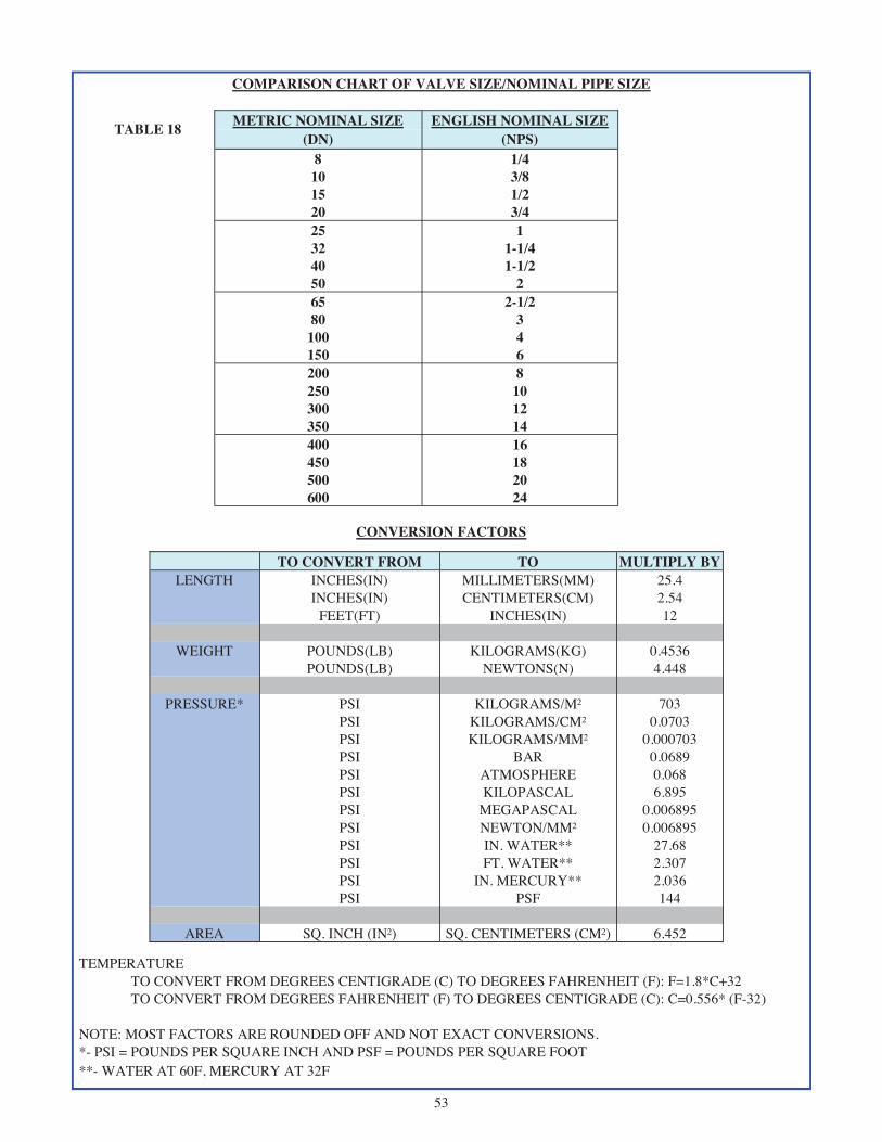
53
COMPARISON CHART OF VALVE SIZE/NOMINAL PIPE SIZE
TABLE 18 METRIC NOMINAL SIZE ENGLISH NOMINAL SIZE (DN) (NPS)
8 1/4 10 3/8 15 1/2 20 3/4 25 1 32 1-1/4 40 1-1/2 50 2 65 2-1/2 80 3
100 4 150 6 200 8 250 10 300 12 350 14 400 16 450 18 500 20 600 24
CONVERSION FACTORS
TO CONVERT FROM TO MULTIPLY BY LENGTH INCHES(IN) MILLIMETERS(MM) 25.4
INCHES(IN) CENTIMETERS(CM) 2.54 FEET(FT) INCHES(IN) 12
WEIGHT POUNDS(LB) KILOGRAMS(KG) 0.4536
POUNDS(LB) NEWTONS(N) 4.448
PRESSURE* PSI KILOGRAMS/M² 703 PSI KILOGRAMS/CM² 0.0703 PSI KILOGRAMS/MM² 0.000703 PSI BAR 0.0689 PSI ATMOSPHERE 0.068 PSI KILOPASCAL 6.895 PSI MEGAPASCAL 0.006895 PSI NEWTON/MM² 0.006895 PSI IN. WATER** 27.68 PSI FT. WATER** 2.307 PSI IN. MERCURY** 2.036 PSI PSF 144
AREA SQ. INCH (IN²) SQ. CENTIMETERS (CM²) 6.452
TEMPERATURE TO CONVERT FROM DEGREES CENTIGRADE (C) TO DEGREES FAHRENHEIT (F): F=1.8*C+32 TO CONVERT FROM DEGREES FAHRENHEIT (F) TO DEGREES CENTIGRADE (C): C=0.556* (F-32)
NOTE: MOST FACTORS ARE ROUNDED OFF AND NOT EXACT CONVERSIONS. *- PSI = POUNDS PER SQUARE INCH AND PSF = POUNDS PER SQUARE FOOT **- WATER AT 60F, MERCURY AT 32F

54
MEASUREMENT EQUIVALENTS
FRACTION DECIMAL MILLIMETERS 1/64 0.0156 0.3969 1/32 0.0313 0.7938
0.0394 1.0000 3/64 0.0469 1.1906 1/16 0.0625 1.5875 5/64 0.0781 1.9844
0.0787 2.0000 3/32 0.0938 2.3813 7/64 0.1094 2.7781
0.1181 3.0000 1/8 0.1250 3.1750
9/64 0.1406 3.5719 5/32 0.1563 3.9688
0.1575 4.0000 11/64 0.1719 4.3656 3/16 0.1875 4.7625 0.1969 5.0000 13/64 0.2031 5.1594 7/32 0.2188 5.5563 15/64 0.2344 5.9531
0.2362 6.0000 1/4 0.2500 6.3500
17/64 0.2656 6.7469 0.2756 7.0000
9/32 0.2813 7.1438 19/64 0.2969 7.5406 5/16 0.3125 7.9375
0.3150 8.0000 21/64 0.3281 8.3344 11/32 0.3438 8.7313
0.3543 9.0000 23/64 0.3594 9.1281
3/8 0.3750 9.5250 25/64 0.3906 9.9219
0.3937 10.0000 13/32 0.4063 10.3188 27/64 0.4219 10.7156
0.4331 11.0000 7/16 0.4375 11.1125 29/64 0.4531 11.5094 15/32 0.4688 11.9063
0.4724 12.0000 31/64 0.4844 12.3031
1/2 0.5000 12.7000
FRACTION DECIMAL MILLIMETERS 0.5118 13.0000
33/64 0.5156 13.0969 17/32 0.5313 13.4938 35/64 0.5469 13.8906
0.5512 14.0000 9/16 0.5625 14.2875 37/64 0.5781 13.6844
0.5906 15.0000 19/32 0.5938 15.0813 39/64 0.6094 15.4781 5/8 0.6250 15.8750
0.6299 16.0000 41/64 0.6406 16.2719 21/32 0.6563 16.6688
0.6693 17.0000 43/64 0.6719 17.0656 11/16 0.6875 17.4625 45/64 0.7031 17.8594
0.7087 18.0000 23/32 0.7188 18.2563 47/64 0.7344 18.6531
0.7480 19.0000 3/4 0.7500 19.0500
49/64 0.7656 19.4469 25/32 0.7813 19.8438
0.7874 20.0000 51/64 0.7969 20.2406 13/16 0.8125 20.6375
0.8268 21.0000 53/64 0.8281 21.0344 27/32 0.8438 21.4313 55/64 0.8594 21.8281
0.8661 22.0000 7/8 0.8750 22.2250
57/64 0.8906 22.6219 0.9055 23.0000
29/32 0.9063 23.0188 59/64 0.9219 23.4156 15/16 0.9375 23.8125
0.9449 24.0000 61/64 0.9531 24.2094 31/32 0.9688 24.6063
0.9843 25.0000 63/64 0.9844 25.0031
1 1.0000 25.4000
TABLE 19

55
March, 2011 THE WILLIAM POWELL COMPANY GENERAL TERMS AND CONDITIONS OF SALE 1. TERMS EXCLUSIVE: The terms and conditions of the purchase order or requisition to which these GENERAL TERMS AND CONDITIONS OF SALE (these “Terms and Conditions”) relate or are attached (each, an “Order”), are exclusive and represent the full and final agreement of The William Powell Company, an Ohio corporation (“Powell”) and the purchaser (“Purchaser”) as they relate to the goods, materials, services or labor covered in the Order (all, whether or not tangible property or goods, the “Products”), and may not be added to, modified, superseded or altered except by written agreement or modification signed by Powell’s authorized representative, notwithstanding any additional or other proposals, terms and conditions which may now or in the future appear on Purchaser’s Orders or other forms (notification of objection thereto being given hereby), in whatever form transmitted, and notwithstanding any shipment of Products, acceptance of payments or other similar acts of Powell. 2. SALE BY AGENT OR REPRESENTATIVE: These Terms and Conditions shall govern the liability and obligations of Powell in regard to the transaction in Products, whether the sale was procured directly by Powell or indirectly through an authorized sales representative. 3. CONTRACT: Orders may be submitted to Powell in writing (which will include via an electronic transmission) or orally, provided, however, that if Purchaser fails to provide a detailed, formal written Order (a) within ten (10) days of an oral Order or (b) before shipment of the Order, whichever is earlier, then Product descriptions, quantities, specifications, etc., as set forth in Powell’s acknowledgement, acceptance and/or invoice, shall be conclusive and binding on both parties, and discrepancies shall be for Pur-chaser’s account. All Orders are subject to credit approval and acceptance by Powell. An Order shall be deemed to have been accepted by Powell upon the first to occur of the following: (i) Powell’s first shipment or other tender of the Order or (ii) acceptance thereof by Powell in writing. 4. PERMISSIBLE VARIATIONS: Powell has the right, prior to the delivery of Products to Purchaser and without the giving of notice to Purchaser, to make any changes in the composition, fabrication or design of the Products which, in the opinion of Powell, do not affect the general characteristics or properties of the Products. In addition, Powell may make any change or any variation in the Products, whether of quality or quantity, which is within governmental or professional standards or specifications applicable at the time of manufacture without giving notice to Purchaser. Purchaser will accept any Products which may incorporate any changes in the composition, fabrication or design. 5. PRICES: Prices for Products are quoted and payable in U.S. dollars (“USD”). Prices stated in general price lists are subject to change without prior notice, at Powell’s sole discretion. Prices that are provided in a specific quotation will remain firm for thirty (30) days of the issued date of the written quotation. All prices are exclusive of freight costs, taxes and duties. All taxes (including, without limitation, sales, use, stamp, value added and other taxes) duties, fees, charges and assessments by whomsoever levied on or with respect to the Products, and whether levied against Purchaser or Powell, are for Purchaser’s account and, unless invoiced, shall be paid by Purchaser directly to the appropriate governmental agency. 6. SHIPPING TERMS: Delivery of Products to Canada, the United States and Mexico shall be F.O.B. (as defined in the Uniform Commercial Code as in effect in the State of Ohio) Powell’s plant of manufacture. Delivery of Products outside of Canada, United States and Mexico shall be Ex Works (as defined by INCOTERMS 2000) Powell’s plant of manufacture. All transportation expenses, freight and insurance shall be paid by Purchaser, and risk of delay, loss or damage incurred in transit shall be borne by Purchaser, who shall be responsible to file any such claims with the relevant carrier(s) or insurers. Upon tender of delivery, title shall pass to Purchaser, subject to Powell’s right of stoppage in transit and to Powell’s security interest in the Products, as set forth in Section 8. If the Products are held by Powell subject to receiving instructions from Purchaser or in any case where Powell, in its sole discretion, determines any part of the Products should be held for Purchaser’s account, Powell may invoice the Products, and Purchaser agrees to make payment in accordance with these Terms and Conditions. Products invoiced and held at any location by Powell will be held at Purchaser’s risk, and Powell may charge for (but is not obligated to carry) insurance and storage. If Purchaser has declared or manifested an intention not to accept delivery in accordance with these Terms and Conditions, no tender will be necessary, but Powell may, at its op-tion, give notice to Purchaser that Powell is ready and willing to deliver and such notice will constitute a valid tender of delivery. 7. INSPECTION AND ACCEPTANCE: Each shipment shall be inspected by Purchaser for observable damage and/or non-conformity at the time of delivery of the Products. Failure to so inspect shall constitute a waiver of Purchaser’s rights of inspection and shall constitute an unqualified acceptance of the Products. If, after such inspection, Purchaser attempts to reject any Products, Purchaser shall fully specify all claimed damage or non-conformity in writing in a notice of rejection sent to Powell within five (5) days of delivery of the Products. Purchaser’s failure to so specify shall constitute a waiver of that damage or non-conformity. Partial deliveries shall be accepted by Purchaser and paid for according to these Terms and Conditions. 8. PAYMENT TERMS: Payment shall be due net thirty (30) days from the date of invoice. Overdue accounts shall be subject to a carrying charge of one and one-half percent (1.5%) per month or portion of a month on the unpaid balance until paid in full. In the event Purchaser shall default on its obligations hereunder, Purchaser shall be liable for all of Powell’s costs and expenses of collection, including reasonable attorneys’ fees. Powell may, at its option, cancel and/or sell any unshipped Products should Purchaser fail to fulfill the complete terms of payment. Purchaser will have no right to offset any amounts against any payment or other obligation which Powell may owe to Purchaser. Powell hereby reserves a security interest in the Products to secure Purchaser’s payment of the purchase price and any other amounts owed by Purchaser, and Purchaser agrees that Powell may (but is not obligated to) take such action as Powell deems advisable to evidence and perfect such interest and that Purchaser will cooperate with Powell in the taking of such actions. 9. CREDIT APPROVAL: Notwithstanding the provisions of Section 8, Powell may at any time decline to make any shipment or delivery or perform any work except upon receipt of payment or upon terms and conditions or security satisfactory to Powell, including, but not limited to, requiring that Purchaser provide Powell one or more letters of credit. 10. LEAD TIMES: Estimated lead times, if specified, are approximate only and are not guaranteed. Failure to ship on or near the estimated date shall not entitle Purchaser to any remedy or to cancel the Order without charge. Estimated lead times are provided Ex Works Powell’s plant in weeks after receipt of Order. Estimated lead times are stated on a net basis and do not include any additional lead time due to scheduled and/or unscheduled plant shutdowns. Scheduled plant shutdowns include a two (2) week shutdown each winter and each summer. Estimated lead times are quoted on the basis of material availability and plant loading at the time of quotation, which are subject to change. Purchaser should confirm any estimated lead times at time of Order. 11. MINIMUM ORDER CHARGE: With respect to any Order that includes spare, replacement or component parts (“Parts”) as Products, a minimum Order charge of One Hundred USD ($100) shall apply. With respect to any Order that includes valves (“Valves”) as Products, a minimum Order charge of Three Hundred Fifty USD ($350) shall apply. 12. RETURN OF PRODUCTS: No Products shall be returned to Powell without Powell’s prior written agreement. Products returned by Purchaser shall be returned in the same condition as when delivery was affected by Powell. Only Products that are new, unused and in a condition suitable for immediate resale shall be considered for return. Powell reserves the right to assess a minimum thirty-five percent (35%) restocking charge for Products returned for reasons other than defects or non-conformity. 13. CANCELLATION/SUSPENSION: Purchaser shall not cancel or suspend an Order without Powell’s prior written consent, which such consent Powell shall be under no obligation to provide. In the event of cancellation or suspension of an Order without Powell’s prior written consent, in addition to Powell’s other rights and remedies available hereunder and under applicable law, Purchaser shall pay cancellation charges as follows: (a) Order entered in Powell’s system, but no engineering yet initiated, 5%, (b) Engineering work has begun and orders for casings and/or outside purchased parts have been placed, 25%, (c) Castings poured and/or components made, but not yet received at Powell’s location, 75%, (d) Castings poured and/or components made and received at Powell’s location, 85%, (e) Manufacturing process started, 95% and (f) Components fin-ished, 100%. Powell may cancel all or part of an Order immediately upon the happening of any of the following: Purchaser is delinquent on any of its obligations hereunder or under any order or transaction with Powell, insolvency of Purchaser; the appointment of a custodian as that term is defined in Title 11 U.S.C., as amended (the “Bankruptcy Code”), or the com-mencement of a case under any chapter of the Bankruptcy Code or the bankruptcy, receivership, insolvency or similar laws of any country for, by or against Purchaser; Purchaser’s suspension or termination of business or assignment for the benefit of creditors; or any event, whether or not similar to the foregoing, which materially impairs Purchaser’s ability to perform hereunder. Powell’s rights to cancel or postpone set forth herein may be exercised by Powell without liability. 14. CORRECTIONS: Powell reserves the right to make corrections to price lists, quotations, invoices or other contract documents in the event of clerical or typographical errors. 15. COUNTRY OF ORIGIN: Powell reserves the right to furnish Products from any of its plants at its sole discretion and does not represent that the Products listed
55

56
herein originate from any specific country. Any costs affected by country of origin, including, but not limited to, customs duties, are not included in the purchase price and are for Purchaser’s account. 16. INFORMATION REGARDING PRODUCTS: Purchaser acknowledges that it has received and is familiar with Powell’s and any other manufacturer’s labeling and literature concerning the Products and will forward such information to its employees, agents and customers. 17. POWELL PRODUCT WARRANTY: For a period of (a) ninety (90) days from tender of delivery with respect to Parts and (b) the earlier of (i) eighteen (18) months from tender of delivery or (ii) twelve (12) months from installation with respect to Valves, Powell warrants to Purchaser that the Parts and/or Valves, as applicable, of its own manufacture are free of defects in material and workmanship, under normal use and proper operation. If any such Products fail to comply with such warranty, Powell, at Pow-ell’s option, shall either: (i) replace such defective Products; (ii) furnish replacement parts for repairing Products (iii) issue written authorization for Purchaser or others to replace or repair, without charge to Purchaser, at costs comparable to Powell’s normal manufacturing costs, those parts proven defective; or (iv) refund all monies paid by Purchaser to Powell for such Products and, at the sole discretion of Powell, have the Products returned to Powell at Powell’s expense. Finished materials and accessories purchased from other manufacturers are warranted only to the extent of the manufacturer’s warranty to Powell (to the extent transferable by Powell to Purchaser). Any alteration in material or design of the Products or component parts thereof by Purchaser or others and/or the undertaking of repairs or replacement by Purchaser or its agents without Powell’s written consent shall relieve Powell of all responsibility herewith. Powell’s obligations under this warranty shall be conditioned upon (a) Purchaser’s notifying Powell of any alleged defect(s) in a writing that references Purchaser’s Order number and provides complete identification of any allegedly defective Products within ten (10) days of the discovery of the damage or defect, and (b) Powell’s satisfying itself upon in-spection that its warranty has been breached. Purchaser may not bring any action under or arising from an Order or these Terms and Conditions unless such action is commenced within one year after the cause of action accrues. EXCEPT AS SET FORTH IN THIS SECTION 17, POWELL MAKES NO WARRANTY CONCERNING THE PRODUCTS WHATSOEVER; POWELL DISCLAIMS AND EXCLUDES ALL OTHER WARRANTIES, EXPRESS OR IMPLIED, INCLUDING, WITHOUT LIMITATION, WARRANTIES OF NON-INFRINGEMENT AND THE IM-PLIED WARRANTIES OF MERCHANTABILITY AND FITNESS FOR A PARTICULAR PURPOSE. THE OBLIGATIONS SET FORTH IN THIS SECTION 17 ARE POW-ELL’S SOLE OBLIGATIONS AND PURCHASER’S EXCLUSIVE REMEDY. POWELL SHALL NOT BE LIABLE FOR ANY DIRECT, INDIRECT, INCIDENTAL OR CONSEQUENTIAL DAMAGES, AND PURCHASER HEREBY WAIVES, FOR ITSELF AND ITS SUCCESSORS AND ASSIGNS, (A) ANY AND ALL CLAIMS FOR PU-NITIVE DAMAGES AND (B) ALL CLAIMS OF NEGLIGENCE OR STRICT LIABILITY OR BOTH. WITHOUT LIMITATION TO THE FOREGOING, IN NO EVENT SHALL POWELL BE LIABLE FOR THE LOSS OF USE OF THE PRODUCT OR FOR THE LOSS OF USE OF ANY OTHER PRODUCT, PROCESS, EQUIPMENT, OR FACILITIES OF PURCHASER OR OF THE END-USER, WHETHER PARTIALLY OR WHOLLY DUE TO DEFECTS IN MATERIAL AND/OR WORKMANSHIP AND/OR DESIGN OF POWELL’S PRODUCT, AND IN NO EVENT SHALL POWELL BE LIABLE FOR REMOVAL OF APPURTENANCES OR INCIDENTALS SUCH AS CONNECTIONS, PIPE WORK AND SIMILAR ITEMS OF OBSTRUCTION OR FOR ANY COSTS BROUGHT ABOUT BY NECESSITY OF REMOVING THE PRODUCT FROM ITS POINT OF INSTALLATION. Purchaser (a) recognizes that the limitations contained in this Section 17 are material factors in Powell’s sale of the Products at the price(s) specified, and (b) agrees that any ac-commodation to Purchaser by Powell, whether for sales policy reasons or otherwise, shall not be taken to establish any liability of Powell or any contract term inconsistent with this Agreement. Purchaser shall neither make nor purport to make (a) any warranty to any person by or on behalf of Powell or (b) any warranty or representation inconsistent with this Section 17. 18. COMPLIANCE WITH LAWS: Powell certifies that the Products produced by it, if any, were produced in compliance with all applicable requirements of Sections 6, 7 and 12 of the Fair Labor Standards Act of 1938, as amended, and the Regulations and Orders of the Administrator of the Wage and Hour Division issued under Section 14 thereof. Powell shall endeavor to comply with all applicable Ohio and United States federal laws. Powell is not responsible for compliance with any other laws or regulations, or with any Product standard or specification, whether of general or particular application, unless Purchaser has furnished specific written notice thereof prior to Powell’s entry of Purchaser’s Order. All sales of Products are conditioned upon and subject to strict compliance with United States export control laws, rules and regulations, including, without limitation, the Export Administration Act, the Export Administration Regulations, the Arms Control Act, the International Traffic in Arms Regulations, the Trading With the Enemy Act, the Interna-tional Economic Powers Act and the Foreign Assets Control Regulations, as they may be amended and supplemented from time to time (each, an “Export Law” and collectively, the “Export Laws”). For any sale of Products requiring a license, permit or other approval under any Export Law (“Restricted Products”), Powell shall determine the feasibility of obtaining such license, permit or other approval (“Export Approval”) and whether it will fill the order for the Restricted Products in light of required Export Approval. In the event Powell applies for Export Approval for the Restricted Products, it shall do so at Purchaser’s cost and expense and Purchaser agrees to reimburse Powell for any cost or expenses (including Powell’s reasonable attorneys’ fees) incurred by Powell in pursuing Export Approval. Powell shall not be under any obligation to ship any such Restricted Products unless and until such Export Approval is granted, and only in strict compliance with the terms and conditions of such Export Approval. Purchaser shall be responsible for timely obtaining and maintaining any required import license, permit or approval necessary to import any Restricted Products into Purchaser’s country and any other required governmen-tal authorization (“Import Approval”). Powell shall not be liable if any Export Approval or Import Approval is delayed, denied, revoked, restricted or not renewed, and Purchaser shall not be relieved thereby of its obligations to pay Powell for the Restricted Products or Powell’s costs and expenses of obtaining Export Approval in respect of Restricted Prod-ucts under the Export Laws. For Products other than Restricted Products, Purchaser (or its designated export agent) shall be responsible for the timely application for any required export authorization and the payment of any required fees, duties, taxes, tariffs, levies or other charges necessary to export the Products out the United States of America and shall be responsible for timely obtaining and maintaining any required Import Approval and the payment of any required fees, duties, taxes, tariffs, levies or other charges necessary to import the Products into Purchaser’s country. Powell shall not be liable if any export authorization or Import Approval is delayed, denied, revoked, restricted or not renewed, and Purchaser shall not be relieved thereby of its obligations to pay Powell for the Products. Purchaser shall not make any disposition of any Products purchased hereunder, by way of transshipment, reexport, diversion or otherwise, other than in and to the ultimate end user and country of destination specified on Purchaser’s order or declared as the ultimate end user and country of ultimate destination on Powell’s invoices, except as the Export Laws or Export Approval may expressly permit. Purchaser shall not distribute or resell any Product to or within any country or to any individual, government authority or other entity that is presently or at any time in the future subject to sanctions of the United States government, or is in violation of any Export Laws or other United States federal laws, statutes, codes, Executive Orders, decrees, rules or regulations relating to terrorism, drug trafficking or money laundering, or is designated under any such authority as being subject to sanctions or connected in any way to terrorism, drug trafficking or money laundering, including, without limitation, on the Specially Designated Nationals List and Block Persons List maintained by the Office of Foreign Assets Control (OFAC), United States Department of the Treasury, and the Denied Persons List, the Entity List and the Unverified List maintained by the Bureau of Industry and Security, United States Department of Commerce. Purchaser shall indemnify and hold harmless Powell from and against any damages, liabilities or expenses of any kind incurred by Powell as a result of Purchaser’s direct or indi-rect breach of any term or condition related to the Export Laws. 19. SAFETY: Purchaser warrants that it will comply with all laws, regulations, standards and requirements which are applicable to the use of the Products and Purchaser’s business. 20. CONFIDENTIALITY: Purchaser will not disclose or otherwise disseminate, directly or indirectly, any of the terms of these Terms and Conditions or any other infor-mation of Powell given to or received by Purchaser or its associates or agents, unless Purchaser received Powell’s written permission or such information is required to be dis-closed by law or becomes part of the public domain through no fault of Purchaser, its associates or agents. 21. GOVERNING LAW; JURISDICTION AND VENUE: These Terms and Conditions shall be governed by and construed in accordance with the internal laws of the State of Ohio, without regard to such state’s choice of law principles. These Terms and Conditions shall not be governed by or construed in accordance with the United Nations Convention on the International Sale of Goods, 1980, for any purpose. Customer and Powell hereby submit to the jurisdiction and venue of the state and federal courts in Cincinnati, Hamilton County, Ohio over any controversy relating to or arising from these Terms and Conditions. Notwithstanding the foregoing, Powell’s right to institute or de-fend any proceedings in any jurisdiction, in or out of the United State of America, shall not be limited. 22. SEVERABILITY: If any of the provisions of these Terms and Conditions are deemed invalid, illegal or unenforceable, the validity, legality and enforceability of the remaining provisions will in no way be affected or impaired thereby.
5756

57
23. FORCE MAJEURE: Delivery of all or any part of the Products is contingent upon Powell’s ability to obtain supplies, raw materials and services through its regular and usual sources of supply. If by reason of any contingency beyond Powell’s reasonable control, including (but not limited to) war, governmental requests, restrictions or regulations, fire, flood, casualty, accident, or other acts of God, strikes or other difficulties with employees, delay or inability to obtain labor, equipment, material and services through Powell’s usual sources, failure or refusal of any carrier to transport materials, delay in transport thereof, or any other similar occurrence, Powell is not able to meet anticipated deliveries, Powell shall not be liable therefore and may, in its discretion without prior notice to Purchaser, postpone the delivery date(s) under this docu-ment for a time which is reasonable under all the circumstances. If during the occurrence of any of the foregoing contingencies, Powell holds any of the Products, Powell may invoice and hold the same for the account of Purchaser and Purchaser agrees to make payment at the maturity of the invoice so rendered. 24. ASSIGNMENT: No right or interest in the contract arising from these Terms and Conditions shall be assigned by Purchaser and no delegation of any obligation owed by Purchaser shall be made without the prior written permission of Powell. As used herein, “Purchaser” and “Powell” include the respective heirs, executors, personal representatives, successors and permitted assigns of each. 25. REMEDIES CUMULATIVE; NO WAIVER: The individual rights and remedies of Powell reserved herein shall be cumulative and additional to any other or further remedies provided in law or equity or in this document. Waiver by Powell of performance or breach of any provision hereof by Purchaser, or failure of Powell to enforce any provision hereof which may establish a defense or limitation of liability, shall not be deemed a waiver of future compliance therewith or a course of performance modifying such provision, and such provision shall remain in full force and effect as written. 26. LIMITATION OF LIABILITY: UNDER NO CIRCUMSTANCES SHALL POWELL BE LIABLE TO PURCHASER UNDER OR IN CONNECTION WITH ORDERS FOR PRODUCTS AND THESE TERMS AND CONDITIONS, WHETHER ANY CLAIM FOR RECOVERY IS BASED UPON OR ARISES OUT OF THEORIES OF BREACH OF CONTRACT, BREACH OF WARRANTY, INDEMNIFICATION, NEGLIGENCE, TORT (INCLUDING STRICT LIABILITY) OR OTHERWISE, IN EX-CESS OF AN AMOUNT EQUAL TO THE NET CONTRACT VALUE OF THE PRODUCTS PROVIDED BY POWELL TO PURCHASER DURING THE MOST RECENTLY ENDED CALENDAR QUARTER.
57

2503 SPR ING GROVE AVENUE, C INCINNATI , OHIO 45214-1771, U.S .A.
www.powellvalves.com