cast steel valves - valve automation - valve repair€¦ · maintenance manual, bolted bonnet gate,...
TRANSCRIPT

VEL–CSVM– 2002
CAST STEEL VALVESMAINTENANCE MANUAL, Bolted Bonnet Gate, Globe, Parallel Slide and Check Valves 2–60”, (50– 1500 mm)
MaintenanceManuals
2
GENERAL INFORMATION PAGE
I INTRODUCTION ........................................................................................................................7
1.1 General Introduction ..............................................................................................................................71.2 Essential Features of Velan Valves........................................................................................................8
II RECEIVING AND PREPARATION FOR INSTALLATION ........................................................................9
2.1 Receiving Inspection ..............................................................................................................................92.2 Quality Control Documentation ............................................................................................................92.3 Storage ....................................................................................................................................................92.4 Handling and Preparation ......................................................................................................................92.5 Instructions for Gate Valves ..................................................................................................................92.6 Instructions for Globe Valves ..............................................................................................................102.7 Instructions for Check Valves ..............................................................................................................102.8 Instructions for Tilting Disc Check Valves ..........................................................................................112.9 Recheck for Bolt Tightness With or Without Line Pressure ..............................................................11
2.9.1 Seat Cleaning / Flushing............................................................................................................11
III WARNINGS ..........................................................................................................................12
IV GENERAL MAINTENANCE ........................................................................................................13
4.1 Trouble Shooting Chart........................................................................................................................134.2 Operation ..............................................................................................................................................14
4.2.1 General ......................................................................................................................................144.2.2 Smoothness of Operation ........................................................................................................14
4.3 Recommended Lubrication..................................................................................................................144.4 General Assembly Information ..........................................................................................................144.5 Body/Bonnet or Cover Torquing Procedure ......................................................................................15
4.5.1 General ......................................................................................................................................154.5.2 Application of Torque................................................................................................................15
V INFORMATION PERTINENT TO GATE, GLOBE AND PARALLEL SLIDE VALVES ..................................18
5.1 Packing ..................................................................................................................................................185.1.1 Number of Packing Rings Required ........................................................................................185.1.2 Packing Ring Replacement on Line ..........................................................................................185.1.3 Repacking with Graphite Packing Rings for Valves Without Leak Off Connection ..............195.1.4 Repacking with Graphite Rings for Valves with Leak Off Connection (Lantern Ring) ........215.1.5 Packing Torques ........................................................................................................................215.1.6 Live-Loading Packings ..............................................................................................................24
5.2 Detailed Maintenance ..........................................................................................................................255.2.1 Packing Chamber Leakage ........................................................................................................255.2.2 Body Bonnet (Gasket) Leakage ................................................................................................255.2.3 Seat Leakage ..............................................................................................................................25
5.2.3.1 General ......................................................................................................................255.2.3.2 Wedge and Disc Repairs – Gate and Parallel Slide ................................................255.2.3.3 Seat Repairs ..............................................................................................................26
5.2.3.3.1 Gate and Parallel Slide Valves ................................................................265.2.3.3.2 Globe,Needle, Stop And Piston Check Valves........................................27
5.2.3.4 Fitting of Repaired Parts ..........................................................................................295.2.3.4.1 Gate Valves................................................................................................295.2.3.4.2 Parallel Slide Valves..................................................................................305.2.3.4.3 Globe, Stop Check, Piston Check Valves ................................................31
5.2.4 Seat Tightness – Closing Torques ............................................................................................32
TABLE OF CONTENTS

3
TABLE OF CONTENTS
5.2.5 Backseat Repairs ........................................................................................................................335.3 Torque Values – Actuator, Yoke/Bonnet Bolting................................................................................34
GATE VALVE PAGE
VI GATE VALVE ........................................................................................................................35
6.1 Types of Gate Valves............................................................................................................................356.2 Gate Valves: Exploded View ................................................................................................................376.3 Partial Disassembly – Gasket Replacement........................................................................................386.4 Total Disassembly ................................................................................................................................38
6.4.1 Disassembly of Body/Bonnet and Wedge/Stem ....................................................................386.4.2 Disassembly of Top Works ......................................................................................................38
6.5 Assembly ..............................................................................................................................................406.5.1 Top Works Assembly ................................................................................................................406.5.2 Bonnet/Body Assembly ............................................................................................................40
GLOBE VALVE PAGE
VII GLOBE VALVE ......................................................................................................................41
7.1 Types of Globe Valves..........................................................................................................................417.2 Globe Valves Rotating Stem: Exploded View ....................................................................................447.3 Globe Valves Non-Rotating Stem: Exploded View ............................................................................457.4 Piston Check Valve: Exploded View ....................................................................................................467.5 Partial Disassembly – Gasket Replacement........................................................................................477.6 Total Disassembly of Globe, Stop Check and Piston Check Valves ................................................47
7.6.1 Disassembly of Body/Bonnet and Disc/Stem/Union ..............................................................477.6.2 Disassembly of Top Works ......................................................................................................48
7.7 Total Disassembly of Piston Check Valves ........................................................................................497.8 Assembly ..............................................................................................................................................50
7.8.1 Top Works Assembly ................................................................................................................507.8.2 Disc and Bonnet/Body Assembly ............................................................................................50
PARALLEL SLIDE VALVES PAGE
VIII PARALLEL SLIDE VALVES ......................................................................................................51
8.1 Parallel Slide Valve : Exploded View ..................................................................................................518.2 Parallel Slide Valve Stem/Disc Carrier/Disc Assembly ......................................................................528.3 Partial Disassembly – Gasket Replacement........................................................................................538.4 Total Disassembly ................................................................................................................................53
8.4.1 Disassembly of Body/Bonnet and Wedge/Stem ....................................................................538.4.2 Disassembly of Top Works ......................................................................................................54
8.5 Assembly ..............................................................................................................................................568.5.1 Top Works Assembly ................................................................................................................568.5.2 Bonnet/Body and Disc/Stem Assembly ..................................................................................56
SWING CHECK AND TILTING DISC VALVES PAGE
IX SWING CHECK VALVE............................................................................................................58
9.1 Types of Swing Check Valves..............................................................................................................589.2 Swing Check Valve: Exploded View....................................................................................................609.3 Types of Tilting Disc Check Valves......................................................................................................61
9.3.1 Tilting Disc Closure Kit Fit-up ..................................................................................................629.4 Partial Disassembly – Gasket Replacement Swing Check and Tilting Disc Valves ........................629.5 Total Disassembly – Tilting Disc..........................................................................................................62

4
TABLE OF CONTENTS
9.6 Detailed Maintenance – Tilting Disc....................................................................................................629.6.1 Body/Cover (Gasket) Leakage ..................................................................................................629.6.2 Seat Leakage-Tilting Disc ..........................................................................................................62
9.6.2.1 Tilting Disc Repairs - General ..................................................................................629.6.2.2 Tilting Disc Seat Repairs - General ..........................................................................639.6.2.3 Bearing Blue or Developer Test (Removal of disc is required) ............................63
9.7 Assembly - Tilting Disc ........................................................................................................................639.7.1 Disc Assembly Fit-Up ................................................................................................................639.7.2 Tilting Disc Adjustment Procedure ..........................................................................................63
9.8 Total Disassembly – Swing Check ......................................................................................................649.9 Detailed Maintenance - Swing Check ................................................................................................65
9.9.1 Body/Cover (Gasket) Leakage ..................................................................................................659.9.2 Seat Leakage ..............................................................................................................................65
9.9.2.1 Disc Repairs ..............................................................................................................659.9.3 Seat Repairs ..............................................................................................................................659.9.4 Bearing Blue or Developer Test (Removal of disc is required) ..............................................659.9.5 Paper or Light Test (Removal of disc is not required) ............................................................679.9.6 Fitting of New Disc ....................................................................................................................68
9.10 Assembly ..............................................................................................................................................689.10.1 Disc Assembly Fit-Up ................................................................................................................689.10.2 Internal and Mid-Section Assembly ........................................................................................68
9.11 Disassembly and Re-assembly of Bolted Cover Testable Swing Check Valve................................699.11.1 Disassembly ..............................................................................................................................699.11.2 Re-assembly ..............................................................................................................................699.11.3 Bolted Cover Positive Assist Swing Check Valve (exploded view)........................................70
9.12 Disassembly and Re-assembly of Bolted Cover Ball Check Valve ..................................................719.12.1 Disassembly ..............................................................................................................................719.12.2 Re-assembly ..............................................................................................................................719.12.3 Ball Check Cage Unit (exploded view)....................................................................................................................72
APPENDIX PAGE
X APPENDIX ............................................................................................................................73
10.1 Procedure for Removing Manual Gear Actuator ..............................................................................7310.1.1 Style 1 ........................................................................................................................................7310.1.2 Style 2 ........................................................................................................................................74
10.2 Procedure for Removing Motor Actuators ........................................................................................7510.3 Procedure for Removing Motor Hydraulic or Pneumatic Actuators ................................................7710.4 Spare Parts ............................................................................................................................................77
TERMS AND CONDITIONS OF SALE ....................................................................................................................78
FIGURES NUMBER PAGE
Automatic reseater machine for grinding/lapping globe seats....................... 5.2G 29Automatic grinding lapping machine for gate valve seats and wedge.......... 5.2C 27
Backseat repair .................................................................................................... 5.2S 33Ball check cage unit (exploded view) ................................................................ 9.12.3 72Bevelgear actuator (exploded view).................................................................. 10.2D 76Body recess–spacer washer gap....................................................................... 9.10A 68Bolted cover ball check valve............................................................................. 9.1C 59Bolted cover positive assist swing check valve (exploded view).................... 9.11.3 70Bolted cover testable swing check valve .......................................................... 9.1D 59Bolt tightening sequence.................................................................................... 4.5A 17Blueing test.......................................................................................................... 5.2H 29Braided graphite packing ring............................................................................ 5.1B 18

5
LIST OF FIGURES
FIGURES (CONT’D) NUMBER PAGE
“C” saw packing removal tool ........................................................................... 5.1F 19Cast iron lapping disc ......................................................................................... 5.2E 28Check for gap disc/disc carrier and retainer plate ............................................ 8.5B 57Clearance verification ......................................................................................... 5.2K 30
Disc assembly clearances................................................................................... 9.9B 66Disc unit ............................................................................................................... 9.8A 64
Examples of coupling ......................................................................................... 10.3A 77
Flat style disc ....................................................................................................... 5.2P 31Flexible packing removal tool cork skew tip..................................................... 5.1E 18Full seating circumference ................................................................................. 5.2J 30
Gate valve API 600 2–12” (50-300 mm)............................................................. 6.1A 35Gate valve API 600 14–24” (350-600 mm)......................................................... 6.1B 35Gate valve API 600 26–28” (650-700 mm)......................................................... 6.1C 36Gate valve API 603 1/2 –20” (15-500 mm)........................................................... 6.1D 36Gate valve (exploded view)................................................................................ 6.2 37Globe valve bolted bonnet 2–14” (50-350 mm) ............................................... 7.1A 41Globe valve bolted bonnet 2–12” (50-300 mm) ............................................... 7.1B 41Globe valve bolted bonnet 14–16” (350-400 mm) ........................................... 7.1C 42Globe valve - non rotating stem (exploded view) ............................................ 7.3 45Globe valve - rotating stem (exploded view).................................................... 7.2 44Globe valve stainless bolted bonnet 1/2 –12” (15-300 mm).............................. 7.1E 43Graphite ribbon packing..................................................................................... 5.1A 18
Inclined check valve: angle of incline and roll angle........................................ 2.7A 10Insertion of first packing ring ............................................................................. 5.1G 19
Lantern ring configuration ................................................................................. 5.1D 18Lapping of disc .................................................................................................... 9.9A 65Lapping of wedge ............................................................................................... 5.2A 26Leak off connection............................................................................................. 5.1J 20Live-loading ......................................................................................................... 5.1K 24Live-loading packing........................................................................................... 5.1L 24Lapping plate....................................................................................................... 5.2D 27
Machining of hanger arm ............................................................................. 9.9F 67Manual gear actuator–Style 1...................................................................... 10.1A 73Manual gear actuator–Style 2...................................................................... 10.1B 74Material removal from disc post .................................................................. 9.9D 66Motor actuator–adapter plate attachment (assembly) .............................. 10.2B 75Motor actuator–adapter plate attachment (exploded view) ..................... 10.2C 76Motor actuator–direct attachment .............................................................. 10.2A 75
Original stem-disc assembly ........................................................................ 5.2F 28
Parallel slide disc clamp................................................................................ 8.5A 57Parallel slide (exploded view)....................................................................... 8.1 51Parallel slide full seating circumference...................................................... 5.2M 31Parallel slide preparation for blue ink test................................................... 5.2L 31Parallel slide valve stem/disc carrier/disc assembly................................... 8.2 52Piston check valve (exploded view) ............................................................. 7.4 46

6
LIST OF FIGURES, DIAGRAM AND TABLES
FIGURES (CONT’D) NUMBER PAGE
Removal of actuators .................................................................................... 10.3B 77
Seven packings shown ................................................................................. 5.1C 18Split packing adapter .................................................................................... 5.1H 19Six o’clock contact......................................................................................... 9.9E 67Six packings installed.................................................................................... 5.1I 20Stop Check valve bolted bonnet 2–14” (50-350 mm)................................. 7.1D 42Stroke limiter type II ...................................................................................... 8.4A 54Swing check styles ........................................................................................ 9.8B 64Swing check valve API 600 2–12”(50-300 mm)............................................ 9.1A 58Swing check valve API 603 2–24” (50-600 mm)...................................................... 9.1B 58Swing check valve (exploded view) ................................................................. 9.2 60
Tapered disc– full seating circumference.................................................... 5.2N 31Tapered disc–hardface deposit ................................................................... 5.2Q 32Tapered disc – thrust pad.............................................................................. 5.2O 31To centralize disc with body seat ................................................................. 9.10B 68Top works styles–gate.................................................................................. 6.4A 39Top works styles–globe ............................................................................... 7.6B 49Top works styles– parallel slide ................................................................... 8.4C 55Torque arm 4 types ....................................................................................... 7.5A 48Twelve o’clock contact .................................................................................. 9.9C 66Types of backseats ........................................................................................ 5.2R 33Type of tilting disc check valve 21/2-12” (65-300 mm) ................................ 9.3 61
Wedge dimensions........................................................................................ 5.2I 30Wedge or disc automatic grinding machine ............................................... 5.2B 26
90º check valve: angle of incline and roll angle .......................................... 2.7B 11
DIAGRAM DIAGRAM NUMBER PAGE
Closing torques.............................................................................................. 5.2A 32
TABLES TABLE NUMBER PAGE
Body /bonnet bolting torque ........................................................................ 4.5A 16
Packing flange stud /nut torques for graphite and PTFE packings forgate & parallel slide valves...................................................................... 5.1A 22
Packing flange stud /nut torques for graphite and PTFE packings for globe valves ............................................................................................... 5.1B 23
Recommended lubrication ........................................................................... 4.3 14
Top works styles–gate.................................................................................. 6.4A 39Top works styles– globe ............................................................................... 7.6A 49Top works styles – parallel slide .................................................................. 8.3A 54Torque values ................................................................................................ 5.3A 34
7
INTRODUCTION I
This manual has been prepared by Velan
engineers, designers and maintenance
personnel to assist you in obtaining many years
of satisfactory service from your cast steel valves.
It will also assist you in restoring your valve to the
best working condition with a minimum of time
and expense.
Velan valves are designed and manufactured based
on many years of research and product development
and are constantly being improved. Before beginning
any major work, we recommend that you read this
booklet carefully at least once to understand the
valve's physical condition.
Please note that if you do not understand the reason
for the service problem, we suggest that you get in
touch with your local Velan representative or call the
Customer Service Manager for technical assistance.
Before beginning any major work, we recommend
that you carefully check the nameplate on the valve
and record the figure number to identify the type and
size of valve. See the “Essential Features of Velan
Valves” form on the following page for an explanation
of Velan “Figure Numbers”.
1.1 GENERAL INTRODUCTION
8
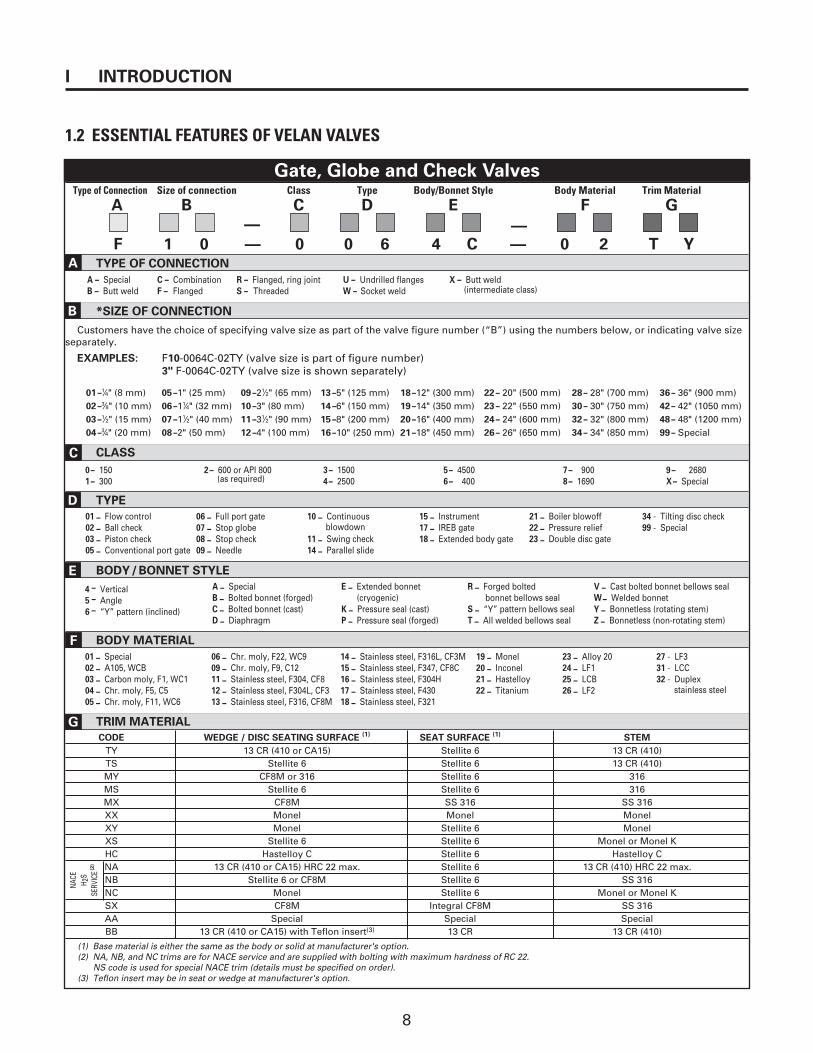
Gate, Globe and Check ValvesType of Connection Size of connection Class Type Body/Bonnet Style Body Material Trim Material
A B C D E F G
— —
F 1 0 — 0 0 6 4 C — 0 2 T YTYPE OF CONNECTION
A – Special C – Combination R – Flanged, ring joint U – Undrilled flanges X – Butt weldB – Butt weld F – Flanged S – Threaded W – Socket weld (intermediate class)
*SIZE OF CONNECTION
Customers have the choice of specifying valve size as part of the valve figure number (“B”) using the numbers below, or indicating valve sizeseparately.
EXAMPLES: F10-0064C-02TY (valve size is part of figure number)3" F-0064C-02TY (valve size is shown separately)
01 –1⁄4" (8 mm) 05 –1" (25 mm) 09 –21⁄2" (65 mm) 13 –5" (125 mm) 18 –12" (300 mm) 22 – 20" (500 mm) 28 – 28" (700 mm) 36 – 36" (900 mm)02 –3⁄8" (10 mm) 06 –11⁄4" (32 mm) 10 –3" (80 mm) 14 –6" (150 mm) 19 –14" (350 mm) 23 – 22" (550 mm) 30 – 30" (750 mm) 42 – 42" (1050 mm)03 –1⁄2" (15 mm) 07 –11⁄2" (40 mm) 11 –31⁄2" (90 mm) 15 –8" (200 mm) 20 –16" (400 mm) 24 – 24" (600 mm) 32 – 32" (800 mm) 48 – 48" (1200 mm)04 –3⁄4" (20 mm) 08 –2" (50 mm) 12 –4" (100 mm) 16 –10" (250 mm) 21 –18" (450 mm) 26 – 26" (650 mm) 34 – 34" (850 mm) 99 – Special
CLASS
0– 150 2– 600 or API 800 3– 1500 5– 4500 7– 900 9– 26801– 300 (as required) 4– 2500 6– 400 8– 1690 X– Special
TYPE
01 – Flow control 06 – Full port gate 10 – Continuous 15 – Instrument 21 – Boiler blowoff 34 - Tilting disc check02 – Ball check 07 – Stop globe blowdown 17 – IREB gate 22 – Pressure relief 99 - Special03 – Piston check 08 – Stop check 11 – Swing check 18 – Extended body gate 23 – Double disc gate05 – Conventional port gate 09 – Needle 14 – Parallel slide
BODY/BONNET STYLE
4 – Vertical A – Special E – Extended bonnet R – Forged bolted V – Cast bolted bonnet bellows seal
5 – Angle B – Bolted bonnet (forged) (cryogenic) bonnet bellows seal W– Welded bonnet
6 – “Y” pattern (inclined) C – Bolted bonnet (cast) K – Pressure seal (cast) S – “Y” pattern bellows seal Y – Bonnetless (rotating stem)D – Diaphragm P – Pressure seal (forged) T – All welded bellows seal Z – Bonnetless (non-rotating stem)
BODY MATERIAL
01 – Special 06 – Chr. moly, F22, WC9 14 – Stainless steel, F316L, CF3M 19 – Monel 23 – Alloy 20 27 - LF302 – A105, WCB 09 – Chr. moly, F9, C12 15 – Stainless steel, F347, CF8C 20 – Inconel 24 – LF1 31 - LCC03 – Carbon moly, F1, WC1 11 – Stainless steel, F304, CF8 16 – Stainless steel, F304H 21 – Hastelloy 25 – LCB 32 - Duplex04 – Chr. moly, F5, C5 12 – Stainless steel, F304L, CF3 17 – Stainless steel, F430 22 – Titanium 26 – LF2 stainless steel05 – Chr. moly, F11, WC6 13 – Stainless steel, F316, CF8M 18 – Stainless steel, F321
TRIM MATERIAL
CODE WEDGE / DISC SEATING SURFACE (1) SEAT SURFACE (1) STEM
TY 13 CR (410 or CA15) Stellite 6 13 CR (410)TS Stellite 6 Stellite 6 13 CR (410)MY CF8M or 316 Stellite 6 316MS Stellite 6 Stellite 6 316MX CF8M SS 316 SS 316XX Monel Monel Monel XY Monel Stellite 6 Monel XS Stellite 6 Stellite 6 Monel or Monel KHC Hastelloy C Stellite 6 Hastelloy CNA 13 CR (410 or CA15) HRC 22 max. Stellite 6 13 CR (410) HRC 22 max.NB Stellite 6 or CF8M Stellite 6 SS 316NC Monel Stellite 6 Monel or Monel KSX CF8M Integral CF8M SS 316AA Special Special SpecialBB 13 CR (410 or CA15) with Teflon insert(3) 13 CR 13 CR (410)
(1) Base material is either the same as the body or solid at manufacturer's option.(2) NA, NB, and NC trims are for NACE service and are supplied with bolting with maximum hardness of RC 22.
NS code is used for special NACE trim (details must be specified on order).(3) Teflon insert may be in seat or wedge at manufacturer's option.
I INTRODUCTION
1.2 ESSENTIAL FEATURES OF VELAN VALVES
A
B
D
E
F
G
NACE
H 2
SSE
RVIC
E(2)
C
9
RECEIVING AND PREPARATION FOR INSTALLATION II
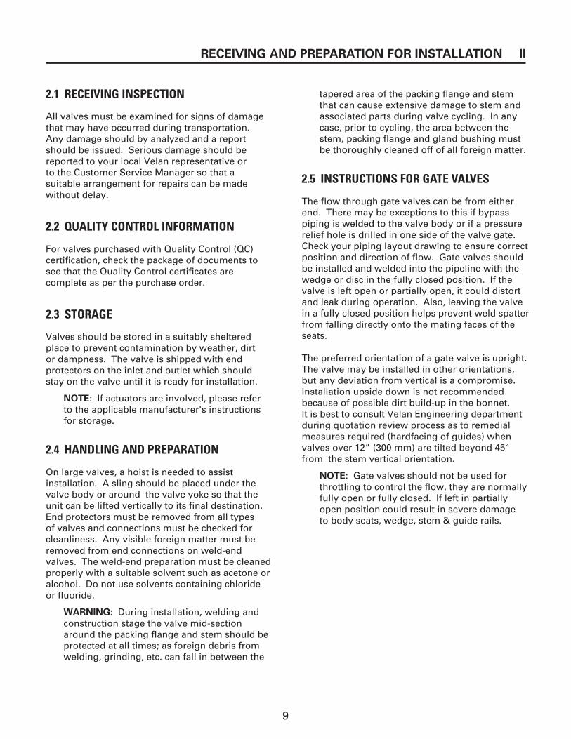
2.1 RECEIVING INSPECTION
All valves must be examined for signs of damagethat may have occurred during transportation.Any damage should by analyzed and a reportshould be issued. Serious damage should bereported to your local Velan representative or to the Customer Service Manager so that a suitable arrangement for repairs can be madewithout delay.
2.2 QUALITY CONTROL INFORMATION
For valves purchased with Quality Control (QC)certification, check the package of documents tosee that the Quality Control certificates arecomplete as per the purchase order.
2.3 STORAGE
Valves should be stored in a suitably shelteredplace to prevent contamination by weather, dirt or dampness. The valve is shipped with endprotectors on the inlet and outlet which shouldstay on the valve until it is ready for installation.
NOTE: If actuators are involved, please referto the applicable manufacturer's instructionsfor storage.
2.4 HANDLING AND PREPARATION
On large valves, a hoist is needed to assist installation. A sling should be placed under thevalve body or around the valve yoke so that theunit can be lifted vertically to its final destination.End protectors must be removed from all types of valves and connections must be checked forcleanliness. Any visible foreign matter must beremoved from end connections on weld-endvalves. The weld-end preparation must be cleanedproperly with a suitable solvent such as acetone oralcohol. Do not use solvents containing chlorideor fluoride.
WARNING: During installation, welding andconstruction stage the valve mid-sectionaround the packing flange and stem should beprotected at all times; as foreign debris fromwelding, grinding, etc. can fall in between the
tapered area of the packing flange and stemthat can cause extensive damage to stem andassociated parts during valve cycling. In anycase, prior to cycling, the area between thestem, packing flange and gland bushing mustbe thoroughly cleaned off of all foreign matter.
2.5 INSTRUCTIONS FOR GATE VALVES
The flow through gate valves can be from eitherend. There may be exceptions to this if bypass piping is welded to the valve body or if a pressurerelief hole is drilled in one side of the valve gate.Check your piping layout drawing to ensure correctposition and direction of flow. Gate valves shouldbe installed and welded into the pipeline with thewedge or disc in the fully closed position. If thevalve is left open or partially open, it could distortand leak during operation. Also, leaving the valvein a fully closed position helps prevent weld spatterfrom falling directly onto the mating faces of theseats.
The preferred orientation of a gate valve is upright.The valve may be installed in other orientations,but any deviation from vertical is a compromise.Installation upside down is not recommendedbecause of possible dirt build-up in the bonnet. It is best to consult Velan Engineering departmentduring quotation review process as to remedialmeasures required (hardfacing of guides) whenvalves over 12” (300 mm) are tilted beyond 45˚from the stem vertical orientation.
NOTE: Gate valves should not be used forthrottling to control the flow, they are normallyfully open or fully closed. If left in partiallyopen position could result in severe damage to body seats, wedge, stem & guide rails.

10
II RECEIVING AND PREPARATION FOR INSTALLATION
2.6 INSTRUCTIONS FOR GLOBE VALVES
Globe valves are usually installed with the inletbelow the valve seat. This must be checked carefully to prevent incorrect installation. If throttlingservice is particularly severe, Velan recommendsthat the valve be installed so that the flow entersover the top of the seat and goes down through it.This maintains the valve in a more stable condition.The amount of wear is minimized and there is lessexternal noise. Valve operation also becomes easier because less torque is required to close the valve.
Globe type valves should be installed and weldedwith the disc in a fully closed position to preventdamage to the valve during installation. Leaving the disc in a fully closed position also prevents weldspatter from falling directly onto the mating faces of the seat and disc.
The preferred orientation of a globe valve is upright.The valve may be installed in other orientations, but any deviation from vertical is a compromise.Installation upside down is not recommendedbecause of possible dirt build-up in the bonnet.
PRECAUTION: Allow time for welding tocool before trying the valve for the firsttime in the pipeline.
20…20…
-5… TO 95…FROM
HORIZONTAL
VE
RT
ICA
L
VE
RT
ICA
L
20…20…
VE
RT
ICA
L
HORIZONTAL
Figure 2.7A Inclined check valve: Angle of incline and roll angle
2.7 INSTRUCTIONS FOR CHECK VALVES
All Velan inclined piston check and stop-checkvalves without springs, when installed in verticalor near vertical line, should have fluid flow upwardand the angle of incline of the line not more than5º past the vertical in the direction of the bonnet.When installed in horizontal or near horizontallines, the valve bonnet should be up and the angleof incline of the line should be not more than 5ºbelow the horizontal. See figure 2.7 for incline androll angle allowable. Consult your Velan represen-tative concerning installation other than that men-tioned above.
NOTE: All check valves should be installed at least ten pipe diameters away from upstreampumps, elbows, fittings or equipment. If closerinstallation is required, please consult the VelanCustomer Service Manager (see Fig. 2.7A & 2.8B).
CAUTION: Velan 90º piston check and stopcheck valves without springs should beinstalled with the bonnet up, and the angleof incline of the line should be no morethan 45° from horizontal. Also, the rollangle of the valve bonnet should be nomore than 45° from side to side.

11
All check valves must be installed with the inlet indirection of arrow. This must be checked carefullybefore installing the valve. Placing a check valvein the opposite direction to the flow will preventthe disc from swinging free and will therefore prevent normal operation of the valve.
2.8 INSTRUCTIONS FOR TILTING DISCCHECK VALVES
Tilting disc check valves can be installed horizon-tally or vertically according to the design specifica-tions and with the inlet in the direction of thearrow. Placing a check valve in the opposite direc-tion to the flow will prevent the disc from swing-ing free and will therefore prevent normal opera-tion of the valve
NOTE: All check valves should be installed at leastten pipe diameters away from upstream pumps,elbows, fittings or equipment. If closer installationis required, please consult the Velan CustomerService Manager.
2.9 RECHECK FOR BOLT TIGHTNESSWITH OR WITHOUT LINE PRESSURE
After valve installation, recheck and retighten thebolts including gland bolts as necessary to the val-ues given as follows:
Gasket bolts: body-bonnet, use Table 4.5APacking bolts: gate and parallel slide valves, useTable 5.1A and for globe valves, use Table 5.1B.All other bolts: use Table 5.3A
RECEIVING AND PREPARATION FOR INSTALLATION II
The tightness of the joint bolt tension and glandbolts should be checked at approximately one yearintervals thereafter. Use bolt tightening procedureas follows:
1. Remove one nut at a time, lubricate stud andnut flats thoroughly with an approved anti- seize compound and torque to recom-mended values shown in Table 4.5A.
2. Remove opposite nut and repeat procedureuntil all nuts have been retorqued.
3. Re-check bolt torque by going once aroundclockwise.
NOTE: If gasket must be replaced, followSection 4.5 Body/Bonnet (or Cover) TorquingProcedure.
2.9.1 Seat Cleaning-Flushing
After installation prior to system test and start-up, it is recommended to clean the valve by flushing line debris matter that may have accumulated inside the valve and between thevalve seating surfaces during Plant constructionand valve installation. Open the valve fully, flushas deemed necessary, then close and open thevalve while flushing. If seat leakage is noted afterflushing repeat the procedure. If the leakage stillpersists, it must be assumed the seating surfacemaybe damaged.
NOTE: If seat must be repaired, follow Section 5.2.3 Seat Leakage.
Flow
45°max. 45°max.
45°max.
Figure 2.7B 90º check valve: Angle of incline and roll angle

12
III WARNING
FOR SAFETY REASONS,it is important to take these precautions
before removing a valve from a line.
☛Personnel making any adjustments on the valves should wear safety equipment normally used to work with fluid in the line where the valve is installed.
☛Before removing the yoke bushing under pressure, the valve should be in fully open posi-tion in order to prevent injuries.
☛Before removing a valve from a line, line pressure must be relieved with no exception.
☛Velan valves can be equipped with a variety of manual gear, electric motor, hydraulic orpneumatic actuators. Generally, all pressure must be relieved from both sides of the valvebefore the actuator is removed.
☛A valve in the fully open position (backseated), should not be jammed-tight (overtorqued),to avoid thermal binding. It is our recommendation that the valve be removed 1/4 turn ofthe handwheel from the fully open position. This will also ensure that packing tightness isverifiable. In gear-operated valves, because of the backlash, it is difficult sometimes toensure this position.
☛Valve standards, such as API and MSS, caution users that successful completion of abackseat test should not be construed as a recommendation by the manufacturer
that a valve may be repacked while it is under pressure.
☛The backseat may be used as a means of stopping or reducing packing leakage until the packing can be replaced under
no pressure. Removal of packing with the valve under pressure is at the owner’s risk.
1. Warning on Over-Pressurization Relief
Under certain conditions, double-seated valveswhich have the integrate cavity filled with fluid andis subjected to increase in temperature can result inexcessive buildup of pressure in the center cavity,leading to pressure boundary failure.
Such situations occur when liquid from condensa-tion, testing fluid, leakage from upstream side, etc.accumulates in the center cavity. If this fluid is notrelieved by some means, over-pressurization mayoccur. It is the responsibility of the purchaser toensure that adequate precautions are taken againstsuch an eventuality.
2. Warning on NACE Conversions
It is extremely important to ensure that valves,when converted to NACE trims in the field are doneby Velan authorized service shops. Unauthorizedconversions can result in failure to carry out post-weld heat treatment and result in severe stresscracks in non-stress relieved areas.
3. Warning on Conversion to Globe Stop Check
Velan globe valves cannot be automatically con-verted to glove stop check valves, without verifyingdesign parameters in detail with Velan Engineering.Any unauthorized conversions may result in thejamming of the disc in the valve.
For further details on the above subjects, pleasecontact the Customer Service Manager.

13
AREA GENERAL PROBLEMS PROCEDURE FOR REPAIR
• Packing compression • Packing chamber leakage• Gland bushing binding Gate, globe & parallel slide:
Section 5.2.1
• Packing worn • Repacking procedure• Stem, packing chamber Gate, globe, parallel slide:
damaged Section 5.1.3
• Gasket damaged • Replacement of gasket• Body or bonnet damaged Gate: Section 6.3
Globe: Section 7.4Swing check: Section 9.4
• Tightness of bolting • Body-bonnet stud torquingGate, globe, parallel slide,swing check & tilting disc: Section 4.5
• Lack of seating torque • Closing torqueGate & Globe: Section 5.2.4
• Damaged seat faces • Seat repair(optional informationavailable upon request)
• Disc movement restricted • Disassembly and reassembly Swing check valves
• Lubrication• Lubrication Gate, globe, parallel slide,
swing check & tilting disc: Section 4.3
• Packing torque• Packing compression Gate, globe & tilting disc:
Section 5.1.5
• Stem thread • Disassembly and reassembly • Yoke nut thread Gate: Sections, 6.3, 6.4, 6.5
Globe: Sections, 7.5, 7.6, 7.7, 7.8Parallel slide: Sections, 8.3, 8.4, 8.5Swing Check, 9.4, 9.5, 9.7, 9.8, 9.10, 9.11, 9.12
PACKING
CHAMBER
LEAKAGE
BODY-BONNET
JOINT LEAKAGE
SEAT
LEAKAGE
OPERATIONAL
SMOOTHNESS
4.1 TROUBLE SHOOTING CHART
GENERAL MAINTENANCE IV

14
4.2 OPERATION
4.2.1 General
All valves require examination before being putinto operation. Additionally, valves should beinspected regularly during operation and shouldreceive prompt attention when trouble arises.As a general rule, valves should be subjected toscheduled maintenance.
4.2.2 Smoothness of Operation
Stem threads, gearing and other working compo-nents outside the fluid area should be lubricatedfrequently and at least once every six months.Specific lubricants and frequency of applicationare shown in the recommended lubrication Tableof Section 4.3. Valves that are not operatedfrequently and which may remain open or closedfor long periods of time should be worked (even ifonly partially) about once a month.
IMPORTANT: Excessive handwheel effort canindicate the following:
1. Improperly lubricated or damagedvalve stem.
2. Valve packing compression too tight(check torque Table 5.1A) .
3. Faulty or damaged valve parts.
4. Foreign particle matter on threads andon stem-packing flange area.
4.4 GENERAL ASSEMBLY INFORMATION
1. The most important fact to be considered isthe cleanliness of all parts. All rust and dirtshould be removed from all parts with a wirebrush or emery cloth. Oil and grease shouldbe removed with suitable solvents.
2. All threaded parts (capscrews, nuts and studs)must be well relubricated. The stem and yokenut threads should be cleaned of all old greasebefore new grease is applied to the threads.All recommended lubricants can be found inSection 4.3. Use correct lubricant for each indi-vidual part.
3. Repaired or replacement parts must bechecked to see if all repair procedures havebeen done and that all replacement parts (e.g.packing rings, gasket, etc.) have been checkedfor size so that they will fit into the valve youare servicing.
4. All orientation marks assigned during disas-sembly must be observed so that correctorientation is maintained. Where applicable,orientation marks should be made on partsnear the body serial number (e.g., wedge, disc,seat etc.)
Recommended lubricant subject to change without notice.
Table 4.3 Recommended lubrication
4.3 RECOMMENDED LUBRICATION
PART LUBRICATION APPLICATION FREQUENCY
Stem Exxon: Ronex MP, Castrol MP Directly to When threadsthreads or equivalent MP group (up to 6500F) threads appear dry
Ronex Extra duty 2 (above 6500F)
Yoke nut Exxon: Ronex MP, Castrol MP Inject through Concurrentlyor equivalent MP group (up to 6500F) grease fitting with stemRonex Extra duty 2 (above 6500F) at hub of yoke thread lubrication
All threaded parts - Anti-seize compound No. 425-A Thin coat on On valveexcept (Crane) or equivalent threads assembly onlystem and yoke nut - Nickel Anti-Seize to MIL-A-90TE
or MOLYKOTE P37
IV GENERAL MAINTENANCE

15
4.5 BODY/BONNET (OR COVER) TORQUINGPROCEDURE
4.5.1 General
1. Clean all studs and nuts. Visually inspect all threads to ensure removal of all foreignmatter, rust, corrosion, burrs and previouslubricants.
2. Liberally cover the stud threads and thesurface under the nut head with FELPROtype C5A Hi-Temp Antiseize compound orapproved equivalent. Also, lubricate thefemale threads of the nuts and nut flats, and wipe off any excess lubricant that mayadhere to any of the stainless steel parts with recommended solvents.
Recommended solvents for this work are:a) unused or redistilled acetoneb) alcohol
3. After tightening bolts by hand, follow the bolt tightening sequence shown in Fig. 4.5A.This sequence depends on the quantity ofbolts used. The drawing illustrates thetightening sequence of different size and class. The bolts should be torqued to the values in accordance with the table materialfor stud threads (see Table 4.5A).
4.5.2 Application of Torque
When applying the torque to the bolts, each boltshould be torqued in steps of approximately 20%of the final torque.
After the final torque has been applied in sequence.It is recommended that the bolts be rechecked oncearound in a clockwise rotation.
On sizes of bolts larger than 1 1/8”, special torquemultipliers with ratios 1:7 or 1:6 should be used fortorquing.
PRECAUTION:1. If tightening sequence is not followed, it
is possible that the gasket will not be compressed evenly, and may result in gasket leakage.
2. Over-torquing can cause deformation of the body or bonnet flange and can also cause joint leakage.
3. Do not use impacting devices to tighten up the bolting on the body/bonnet (cover). Use suitable mechanical devices for tightening.
4. Use hand torque wrenches. If torque wrenches are not suitable, use standardwrenches and the following guidelines will apply:
BOLT SIZE LENGTH OF WRENCHinches mm
3/8” 5” 1251/2” 6” 1509/16” 9” 2255/8” 12” 3003/4” 18” 4507/8” 24” 6001” 30” 7501 1/8” 36” 900
GENERAL MAINTENANCE IV

16
BOLTING MATERIAL
Stud Size
B7M/L7M B7/B16 660 630 B8M CL.1 B8M CL.2
3⁄8 –16 UNC 15 (20) 20 (27) 20 (27) 20 (27) 15 (20) 20 (27)
7⁄16 –14 UNC 25 (34) 30 (41) 25 (34) 35 (47) 25 (34) 25 (34)
1⁄2 –13 UNC 40 (54) 50 (68) 40 (54) 55 (75) 35 (47) 45 (61)
9⁄16 – 12 UNC 55 (75) 70 (95) 60 (81) 80 (108) 55 (75) 65 (88)
5⁄8-11 UNC 75 (102) 100 (136) 80 (108) 100 (136) 70 (95) 85 (115)
3⁄4 –10 UNC 135 (183) 170 (231) 150 (203) 200 (271) 125 (170) 150 (203)
7⁄8 –9 UNC 200 (271) 270 (366) 250 (339) 300 (407) 200 (271) 200 (271)
1–8 UNC 350 (475) 400 (542) 350 (475) 450 (610) 300 (407) 350 (475)
11⁄8-8 UN 500 (678) 600 (814) 500 (678) 650 (881) 450 (610) 450 (610)
11⁄4-8 UN 675 (915) 850 (1153) 700 (949) 950 (1288) 650 (881) 650 (881)
13⁄8-8 UN 900 (1220) 1200 (1627) 1000 (1356) 1300 (1763) 900 (1220) 900 (1220)
11⁄2 –8 UN 1200 (1627) 1500 (2034) 1300 (1763) 1700 (2305) 1200 (1627) 1200 (1627)
15⁄8 –8 UN 1600 (2170) 2000 (2712) 1700 (2305) 2200 (2983) 1500 (2034)
13⁄4 –8 UN 2000 (2712) 2500 (3390) 2100 (2848) 2800 (3797) 1900 (2576)
17⁄8–8 UN 2500 (3390) 3100 (4204) 2600 (3526) 3500 (4746) 2300 (3119)
2–8 UN 3000 (4068) 3800 (5153) 3200 (4339) 4200 (5695) 2800 (3797)
21⁄8 – 8 UN 3600 (4882) 4500 (6102) 3800 (5153) 5000 (6780) 3400 (4610)
21⁄4 – 8 UN 4400 (5966) 5400 (7322) 4600 (6238) 6100 (8272) 4100 (5560)
21⁄2 – 8 UN 6000 (8136) 7500(10170) 6400 (8678) 8500 (11526) 5700 (7729)
Table 4.5A Body/bonnet bolting torque ft.lb (N.m).
Note:(1) Torque tolerance ±10%.(2) Maximum temperature for 630 is 650°F.(3) For temperatures above 750°F (400°C) use 75% of the torque values.(4) Above torque values are with the bolts lubricated.
IV GENERAL MAINTENANCE

17
Figure 4.5A Bolt tightening sequence
GENERAL MAINTENANCE IV

18
5.1 PACKINGNOTE: All Cast Steel Valves having 13SX as the last four digits of the figure number (see p.8) come standard with teflon packingsand gasket. These valves may, as an option,come with graphite packings and gasket but this must be requested at time of order, in such a case an orange tag stating graphitepacking and gasket will be attached to the valve.
5.1.1 Number of packing rings required
Number of packing rings ( Figs 5.1A and 5.1B )required without a leak off connection:
(1) For cast gate and parallel slide valves up to 12", 5-6 packings are required.
(2) For cast gate valves 14” and up,6-7packings are required.
(3) For standard cast globe valves, 6-7packings are required.
(4) For cast globe valves, non-rotating stem5-6 packings are required (Fig. 5.1C)
5.1.2 Packing Ring Removal on Line
Follow warning instructions in Section III beforereplacing packing rings on line.
1. Remove the packing flange nuts and, if fit withlive-loading, remove Belleville spring washers.
2. Lift packing flange and gland bushing as highas possible and secure.
3. For braided packing rings: Fig. 5.1C & D usespecial flexible removal tools (cork screw tip)Fig. 5.1E screw into the packing ring and pullout.
Figure 5.1A Graphite ribbon packing
Figure 5.1B Braided graphite packing ring
Braidedpacking
Graphiteribbonpackings
Braidedpacking
Figure 5.1C Seven packings shown
Lantern ring
BraidedpackingGraphite
ribbonpacking
Graphiteribbonpacking
Braidedpacking
Braidedpacking
Braidedpacking
Figure 5.1D Lantern ring configurationFigure 5.1E Flexible packing removal toolcork screw tip
V INFORMATION PERTINENT TO GATE, GLOBE, CHECK &PARALLEL SLIDE VALVES

19
For graphite ribbon packing Fig 5.1C & D with special “C”-saw tool Fig. 5.1F cut through thepackings, apply downward pressure as you workthe tool in a back and forth motion. Blow out pack-ing remains using instrument air or suck out witha vacuum cleaner. Care must be taken not toscratch the stem or the walls of the packing cham-ber during the removal of the packing rings.
4. If the valve is equipped with a leak-off pipe,there is a lantern ring after the third packingring. To remove the lantern ring, insert twohooks into the holes at the top of the lanternring or insert screw-in extracting wires wheretapped holes are provided. These tappedholes are 6-32 UNC for valves 21/2” (65 mm) to 4” (100 mm), and 8-32 UNC for valves 6”(150 mm) and larger.
5. After the lantern ring is lifted, the last fourpacking rings can be removed using the procedure described in step 3.
5.1.3 Repacking with Graphite Packing Rings for Valves Without Leak-off Connection
1. Before repacking, check the stem and the packing chamber wall for damage. Packing Chamber: Scratches (damage) nodeeper than 0.010” (0.25 mm) per side can beremoved by polishing the surfaces with a buffing wheel (120 - 220 grit) or by machiningthe entire packing chamber surface. The sur-face finish should be 16 RMS or better.Stem: Scratches (damage) no deeper than0.010” (0.25 mm) per side can be removed bymachining the entire stem smooth portion upto the back seat. Surface finish should be 16 RMS or better.
21⁄2”–6003” and up150 /300 /600
2”–150 /300 /6002 1⁄2”–150 /300
Split packing adapter
2 1⁄2”–6003” and up21⁄2”–150/300
2”–150 /300 /600150 /300 /600
Figure 5.1G Insertion of first packing ring
Figure 5.1H Split packing adapter
Figure 5.1F ”C”-saw packing removal tool
2. Insert the first packing ring (braided graphitetype, end ring) manually and place as deepinto the packing chamber as possible followedby 1 graphite ribbon (intermediate packingring). Refer to Fig. 5.1G.
3. Insert the split packing adapter (Fig. 5.1H).Push the packing rings to the bottom of thechamber, making sure that the lap joint is notreversed during the operation.
INFORMATION PERTINENT TO GATE, GLOBE, CHECK & VPARALLEL SLIDE VALVES

20
4. Place the gland bushing and packing flangeinto position and compress the bottom packing by tightening the nuts to 130% of the torque value shown in Table 5.1A & B.
NOTE: Ensure gland bolts/nuts are well lubricated with anti-seize compound.
5. Remove the nuts and split packing adapters(Fig. 5.1H), insert the next graphite ribbonpacking and repeat the procedure above untilall intermediate graphite ribbon packings havebeen torqued.
NOTE:
a) The split lap joints of each consecutive ringshould be staggered at approximately 120°so that the fourth ring installed has its lap back at the starting point (Fig. 5.I).Subsequent packing rings should berepacked in the same manner until the special packing adapters are no longerrequired and the standard gland bushing can be used.
b) In case valves are equipped with live-loading (Belleville spring washers) removespring washers during precompression ofpacking rings, and reinstall at final torque.
6. Remove the nuts and split packing adapterand insert the last end ring (braided graphitetype) lower gland bushing and check for bushing positive engagement with packingchamber.
NOTE: As a rule of thumb 1⁄4” (6 mm) min.engagement of the gland bushing inside the packing chamber is required (Fig. 5.1I).Lower the gland flange, relubricate the glandstuds/nuts using anti-seize compound andtorque to values shown in Table 5.1A or Band/or project drawing. Cycle the valve once,for approximately the length of the packingchamber, first cycle, open then close andretighten to the appropriate torque value.
7. Repacking valves using “packing consolida-tion method”. When split packing adapters isnot available use the following procedure:
a) Insert one braided packing ring, followed byintermediate graphite packings and one lastbraided packing ring refer to Fig. 5.1C.Lower the gland bushing and check for bushing positive engagement, see note in step 6.
b) Torque down the gland bolts to torque values shown in Table 5.1A & B.
c) Cycle the valve approximately the length of the packing chamber. First open thenclose and retighten the gland bolts toappropriate torque values. Repeat this step approximately four, five times until the packings become fully consolidated (no more loss of torque)
NOTE: For motor operated valves (mov) usemov manual override handwheel to cycleopen & close.
2 1⁄2” –6003” and up150 /300 /600
2”–150 /300 /6002 1⁄2” –150/300
Figure 5.1I Six packings installed
MIN 1⁄4”
2 1⁄2” – 6003” and up150 /300 /600
2” – 150 /300 /6002 1⁄2” – 150 /300
Figure 5.1J Leak off connection
V INFORMATION PERTINENT TO GATE, GLOBE, CHECK &PARALLEL SLIDE VALVES
21
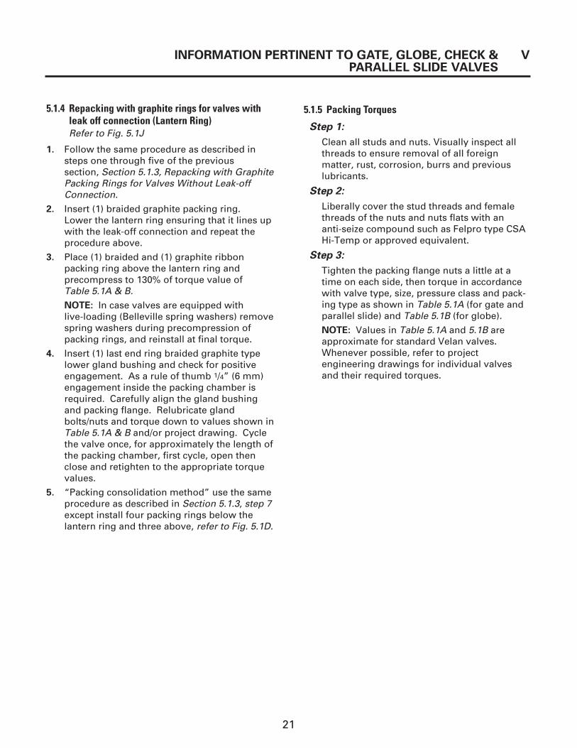
5.1.4 Repacking with graphite rings for valves withleak off connection (Lantern Ring)Refer to Fig. 5.1J
1. Follow the same procedure as described insteps one through five of the previous section, Section 5.1.3, Repacking with GraphitePacking Rings for Valves Without Leak-off Connection.
2. Insert (1) braided graphite packing ring. Lower the lantern ring ensuring that it lines upwith the leak-off connection and repeat the procedure above.
3. Place (1) braided and (1) graphite ribbon packing ring above the lantern ring and precompress to 130% of torque value of Table 5.1A & B.
NOTE: In case valves are equipped with live-loading (Belleville spring washers) removespring washers during precompression ofpacking rings, and reinstall at final torque.
4. Insert (1) last end ring braided graphite typelower gland bushing and check for positiveengagement. As a rule of thumb 1/4” (6 mm)engagement inside the packing chamber isrequired. Carefully align the gland bushingand packing flange. Relubricate glandbolts/nuts and torque down to values shown inTable 5.1A & B and/or project drawing. Cyclethe valve once, for approximately the length ofthe packing chamber, first cycle, open thenclose and retighten to the appropriate torquevalues.
5. “Packing consolidation method” use the sameprocedure as described in Section 5.1.3, step 7except install four packing rings below thelantern ring and three above, refer to Fig. 5.1D.
5.1.5 Packing Torques
Step 1:
Clean all studs and nuts. Visually inspect allthreads to ensure removal of all foreignmatter, rust, corrosion, burrs and previouslubricants.
Step 2:
Liberally cover the stud threads and femalethreads of the nuts and nuts flats with an anti-seize compound such as Felpro type CSAHi-Temp or approved equivalent.
Step 3:
Tighten the packing flange nuts a little at atime on each side, then torque in accordancewith valve type, size, pressure class and pack-ing type as shown in Table 5.1A (for gate andparallel slide) and Table 5.1B (for globe).
NOTE: Values in Table 5.1A and 5.1B areapproximate for standard Velan valves.Whenever possible, refer to projectengineering drawings for individual valves and their required torques.
INFORMATION PERTINENT TO GATE, GLOBE, CHECK & VPARALLEL SLIDE VALVES

22
Note:(1) The torque table is based on a packing compression (PC) of 3500 psi. For other PC simply multiply the above torque values by:
PC new (psi)/3500
(2) The torque values listed are for standard Velan valve designs. For other valve sizes and/or stud diameters contact the VelanCustomer Service Manager.
(3) Torque tolerances ± 10%
(4) If the packings are installed individually and pre-compressed, use the torque values as in the table.
(5) If the packings are installed as a set without individual pre-compression, use “packing consolidation method” see step 7, cyclethe valve 5 times and ensure that after each cycle the gland bolts are torqued to the 100% value.
V INFORMATION PERTINENT TO GATE, GLOBE, CHECK &PARALLEL SLIDE VALVES
Valve Stud API 600 Gate and Parallel Slide Size Dia. 150 300 600 900 1500
inches inches(mm) ft.lb N.m ft.lb N.m ft.lb N.m ft.lb N.m ft.lb N.m
23⁄8 9 12 9 12 9 12
(50) 5⁄8 18 25 18 2521/2
3⁄8 9 12 9 12(65) 1⁄2 13 18
3 1⁄2 13 18 13 18 15 20(80) 5⁄8 28 39 28 39
4 5⁄8 18 25 18 25 20 27(100) 3⁄4 36 49 36 49
6 5⁄8 26 36 26 36 41 56(150) 3⁄4 55 75 55 75
8 5⁄8 28 39 31 42(200) 3⁄4 52 70 77 105
10 5⁄8 31 42(250) 3⁄4 47 64 58 79
12 3⁄4 49 66 52 70 74 100(300)
14 3⁄4 55 75(350) 11⁄8 139 189
16 3⁄4 58 79 58 79(400) 11⁄8 146 198
18 7⁄8 67 92 85 116(450) 11⁄8 152 206
20 1 97 132 102 138(500) 11⁄4 181 246
24 11⁄4 139 189 152 206(600) 11⁄4 224 303
26 1 131 177 148 200(650)
28 7⁄8 86 117(700)
30 1 148 200 148 200(750) 13⁄8 154 209
32 1 148 200(800)
36 13⁄8 262 355 262 355(900) 11⁄2 217 294
42 11⁄8 217 294(1050)
48 11⁄4 349 474(1200)
60
(1500)
Table 5.1A Packing flange stud/nut torques in ft.lb (N.m) for Graphite and PTFE packings–Gate and Parallel Slide

23
Valve Stud API 600 Globe
Size Dia.150 300 600 900 1500
inches inches
(mm) ft.lb N.m ft.lb N.m ft.lb N.m ft.lb N.m ft.lb N.m
2 3⁄8 9 12 9 12 9 12
(50) 5⁄8 18 25 18 25
21/23⁄8 9 12 9 12
(65) 1⁄2 13 18
3 1⁄2 13 18 13 18 15 20
(80)
4 5⁄8 18 25 18 25 26 36
(100)
5 5⁄8 28 39
(125)
6 5⁄8 28 39 28 39
(150) 3⁄4 49 66
8
5⁄8 31 42
(200)3⁄4 52 70
1 102 138
10 3⁄4 49 66 52 70
(250)
12 3⁄4 58 79 58 79
(300)
14 3⁄4 58 79 58 79
(350)
16 3⁄4 74 100 74 100
(400)
18
(450)
Note:
(1) The torque table is based on a packing compression (PC) of 3500 psi. For other PC simply multiply the abovetorque values by: PC new (psi)/3500
(2) The torque values listed are for standard Velan valve designs. For other valve sizes and/or stud diameters contactthe Velan Customer Service Manager.
(3) Torque tolerances ± 10%
(4) If the packings are installed individually and pre-compressed, use the torque values as in the table.
(5) If the packings are installed as a set without individual pre-compression, use “packing consolidation method” seestep 7, cycle the valve 5 times and ensure that after each cycle the gland bolts are torqued to the 100% value.
Table 5.1B Packing Flange Stud/Nut torques in ft.lb (N.m) for Graphite and PTFE Packings–Globe
INFORMATION PERTINENT TO GATE, GLOBE, CHECK & VPARALLEL SLIDE VALVES

24
Figure 5.1K Live-loading
V INFORMATION PERTINENT TO GATE, GLOBE, CHECK &
PARALLEL SLIDE VALVES
5.1.6 Live-Loading Packings
The basic part necessary for achieving the live-loading on packings consist of longer glandstuds/eyebolts, Belleville washers , guide sleeveand guide ring (see Fig. 5.1K)
Installation of the packing rings follows theprocedures described in Sections 5.1.3 & 5.1.4(‘without’ and ‘with’ a leak-off connection, respectively). The Belleville washers are not to beused while compressing individual packing into the packing chamber. However, if packingconsolidation method is used as described inSection 5.1.3 step 7, the belleville spring washers(live-loading) must be in place prior to compress-ing the packings.
IMPORTANT: 1/4” (6 mm) engagement of thegland bushing into the packing chamber isessential to ensure that the packing does notblowout. Velan’s standard live-loaded packingconfiguration for bolted bonnet valves is illustrated in Fig. 5.1L.
Assembly Procedure:1. On each gland stud/eyebolt, place guide ring
on the packing flange, a guide sleeve, a stackof Belleville washers (either single or doublestack depending on application), and a glandnut.
Guidesleeve
Figure 5.1L Live-loaded packing
Single stacked
2. Tighten the gland nuts a little at a time on eachside to the torque values indicated in Table 5.1A & B
Gland nut
Bellevillewasher
Flatwasher
Longerglandstuds
3 to 12”bonnet
2 to 21⁄2”bonnet
Guidesleeve
Double stacked

25
5.2 DETAILED MAINTENANCE
5.2.1 Packing Chamber Leakage
If moisture or dripping occurs around the stem of the ID packing chamber, the following pointsmust be investigated before removing the packing:
1. Check if the packing flange is torqued down tothe correct torque as shown in Table 5.1A & B
2. Check if the live-load arrangement is in correct order. Compare your live-loadingarrangement with Fig. 5.1K. If it is not correct,open the valve to the backseat position andtighten up on the back seat firmly.
3. Check if the gland bushing is binding againstthe packing chamber wall or stem. If so, fullyopen the valve and tighten the stem againstthe backseat firmly. Loosen the packing flangeand realign the gland bushing. Tighten up thepacking flange a little at a time on each side,then torque down to the correct torque asshown in Table 5.1A & B.
4. After retightening, cycle the valve once for approximately the length of the packingchamber, first open then close and retightennuts to original torque value (Table 5.1A & B).If steps 1 through 4 do not stop leakage, pro-ceed with the removal and replacement of thepacking rings.
5.2.2 Body/Bonnet (Gasket) Leakage
To maintain the tightness of a factory–testedbolted bonnet valve, it is essential to apply sufficient bolt tension at all times by having theproper torque on the nuts. The original torquemight be lost due to vibration, relaxation of material caused by frequent temperature and pressure fluctuations, or by creep in high temperature applications. Gasket bolt tension
CAUTION: You must determine the effec-tiveness of the backseat seal as you dismantlethe live-loading arrangement. If leakageoccurs during disassembly, line pressuremust be shut off. Reassemble live-loadingarrangement in correct order, then torquedown to the correct torque as shown in Table 5.1A & B.
should be checked at approximately one–year inter-vals and if necessary , retighten bolts in accordancewith Section 2.9 Recheck For Bolt Tightness.
NOTE: Standard gasket material is corrugatedsteel with graphite in the channels or spiralwound gasket. For alternate gasket materialscontact our service department.
5.2.3 Seat Leakage
5.2.3.1 General
An indication of a valve leak is a pressure loss inthe high pressure line side after a valve has beenproperly closed. In the case of hot water or steamlines, note whether the downstream pipe remainshot beyond the usual length of time. This type ofleak may be the result of a distorted seat caused byimproper welding of the valve into the pipeline orseating damaged caused by foreign particle matteror by stress relieving temperatures that may havebeen used during installation.
Leaks can also develop from failure to close thevalve tightly, resulting in high-velocity flow througha small opening. The hardfacing material (e.g.Stellite 6) is corrosion and erosion-resistant, butgrooves, pit marks or other surface irregularitiesmay still form on the mating surfaces. Valves whichleak should be repaired as quickly as possible toprevent greater damage caused by high velocity.
5.2.3.2 Wedge and Disc Repairs - Gate and Parallel Slide Valves
1. Disassemble valve as described in Section 6.4for gate valves and Section 8.3 for parallel slidevalves, and inspect the wedge or disc forscratches or damage.
2. If seating faces are scratched, the wedge or discmust be lapped. Slight pitting, grooving orindentations no deeper than 0.005” (0.1 mm)can be removed by lapping. If defects cannotbe corrected by lapping, wedge or disc shouldbe ground or machined.
For Wedge Gate Velan recommends that amaximum of 0.015” (0.4 mm) on each side beremoved from a 10-degree seated wedge and0.010” (0.25 mm) on each side for a 7-degreeseated wedge.
For Parallel Slide Disc Gate Velan recommendsmaximum removal of 0.040” (1 mm) per disc.
INFORMATION PERTINENT TO GATE, GLOBE, CHECK & VPARALLEL SLIDE VALVES

26
V INFORMATION PERTINENT TO GATE, GLOBE, CHECK &
PARALLEL SLIDE VALVES
NOTE: If more than 0.035” (0.89 mm) totalmust be removed from both discs and seats of a parallel slide valve, then the retainer plate (45) and or disc groove must also beground, milled or machined to compensate for gap allowance.
3. For the lapping, a flat plate, preferably castiron, should be used and an abrasive lapping compound mixed with olive oil should be evenly distributed over the plate as shown in Fig. 5.2A. Only light, even pressure should beapplied to the plate, lifting the wedge or disc as often as possible to prevent accumulation of particles in one area and to allow for properdistribution of the lapping compound. The lapping plate should be turned slightly everyfew strokes to maintain a flat surface. The part should be lapped until seating faces aresmooth. Velan recommends the use of CloverCompound (silicone carbide) grade “E”medi-um course and grade“C” fine grit compoundfor finishing or an approved equivalent.
Figure 5.2B Wedge or disc automatic grinding machine
4. Thoroughly clean off the lapping compoundwith a suitable cleaning fluid such as acetoneor alcohol. Do not use solvents containingchloride or fluoride
NOTE: If lapping cannot be performed thewedge or disc seating surface should beground using an automatic grinding machineFig 5.2B. For major damage use 60-80 grit,diamond or Micron Alumina stick on abrasivediscs and finish with fine grit 180 and up. For minor imperfections use stick on abrasive
Figure 5.2A Lapping of wedge
medium course 120 grit and finish with 180-220 fine grit.
5.2.3.3 Seat Repairs
5.2.3.3.1 Gate & Parallel Slide Valves1. If seating faces are damaged, the body seat
must be corrected by lapping. Slight pitting,scratches or indentations no deeper than0.005” (0.1 mm) can be removed by lapping.If defects cannot be corrected by lapping, the seats should be ground using specializedautomatic grinding/lapping equipment. Velanrecommends a maximum of 0.015” (0.4 mm)per side that can be removed from a 10°seated valve, and 0.010” (0.25 mm) per sideon a 7° seated valve.
For parallel slide valves, a maximum of 0.040:(1 mm) per seat can be removed, see “NOTE”in Section 5.2.3.2 step 2. Grinding the seatusing automatic grinding equipment can save considerable time, refer to Fig. 5.2C.For major damage use 60-80 grit, diamond or Micron Alumina stick on abrasive discs.For minor damage use 120-180 grit and for finishing, fine grit 220 and up can be used.For details contact our Customer Service Dept.
2. In those cases where the automatic grindingand lapping machine is not employed, seatfaces must be repaired using a lapping plate.The plate should be made of cast iron if possible and should be large enough to coverthe face of the seat (Fig. 5.2D). Apply lappingcompound mixed with olive oil and distribute

27
Figure 5.2C Automatic grinding lappingmachine for gate valve seatsand wedges
View A
View B
INFORMATION PERTINENT TO GATE, GLOBE, CHECK & VPARALLEL SLIDE VALVES
evenly over the plate. Lap seat by movinglapping plate in a circular motion on seat face. Lift the plate as often as possible to prevent accumulation of particles in one area and to allow for proper distribution of the lapping compound. Lap until both seats have smooth faces and then clean off the lapping compound very thoroughly with a suitablecleaning fluid such as acetone or alcohol.
NOTE: Velan recommend the use of clovercompound (silicon carbide) grade “E” medium course for minor imperfections andgrade “C” fine grit compound for finishing.
Figure 5.2D Lapping plate
5.2.3.3.2 Globe, Needle, Stop andPiston Check Valves
1. Disassemble the valve as described in Section 7.5.1 for globe valves, stop checkvalves and piston check valves. Inspect thedisc and the seat for scratches, pitting marksor other damage.
2. If there are indentations or pitting marks nodeeper than 0.005” (0.1 mm), a cast iron lapping disc (Fig. 5.2E) with the proper seatangle must be used with a suitable lappingcompound to roughen the surface first with the use of a new or refurbished original disc

28
(Fig 5.2F), use a fine lapping compound to final lap the disc and seat together.
NOTE: For body seat damage exceeding0.005” (0.12 mm) up to a maximum; for globeB.S. model, needle valve, stop check and pis-ton check having a seat angle of 30°, 0.040” (1 mm) can be removed by grinding with theautomatic grinding machines Fig. 5.2G. Formajor seat damage use 60-80 grit, diamond ormicron Alumina stick on abrasive discs, andfinish with fine grit 180 and up. For minorimperfections use medium course 120 gritstick on abrasive discs and finish with fine grit,180 and up.
For the valve disc seating surface damageexceeding 0.005” (0.12 mm), up to maximum of 0.040” (1 mm) can be removed. For globe,B.S. model, needle disc, stop check and pistoncheck with disc angle of 27°. Chuck and centerthe disc in a lathe machine, remove only asneeded up to the maximum indicated above.The repaired disc should be mated fine lappedwith the body seat as shown in Fig. 5.2F.
V INFORMATION PERTINENT TO GATE, GLOBE, CHECK &
PARALLEL SLIDE VALVES
Cast ironlapping disc
Figure 5.2E Cast iron lapping disc
IMPORTANT: A guiding plate for the stem is required to maintain alignment during the lapping operation. Refer to Fig 5.2F. It should be made of wood or any other suitable material to the same gasket dimensions as the bonnet.
The section of the plate where the stemextends through should be made 1/64” (0.4 mm) larger than the stem diameter.
3. Place a small quantity of lapping compoundmixed with olive oil and evenly distribute onthe two mating surfaces.
4. It is important to apply slight pressure whenlapping seats and to rotate reciprocally. Forbest results, use an air or electric hand toolwith adjustable speed and reciprocal move-ment. The lap should be lifted frequently andturned to a new starting position so that thelapping will be rotated over a new area.
5. In order to ensure that the pressure is appliedevenly, it is necessary, on some valves, tosuspend the disc and stem assembly from acoil spring as shown in Fig. 5.2E.
Figure 5.2F Original stem/disc assembly
Originalstem/discassembly
Guidingplate
29
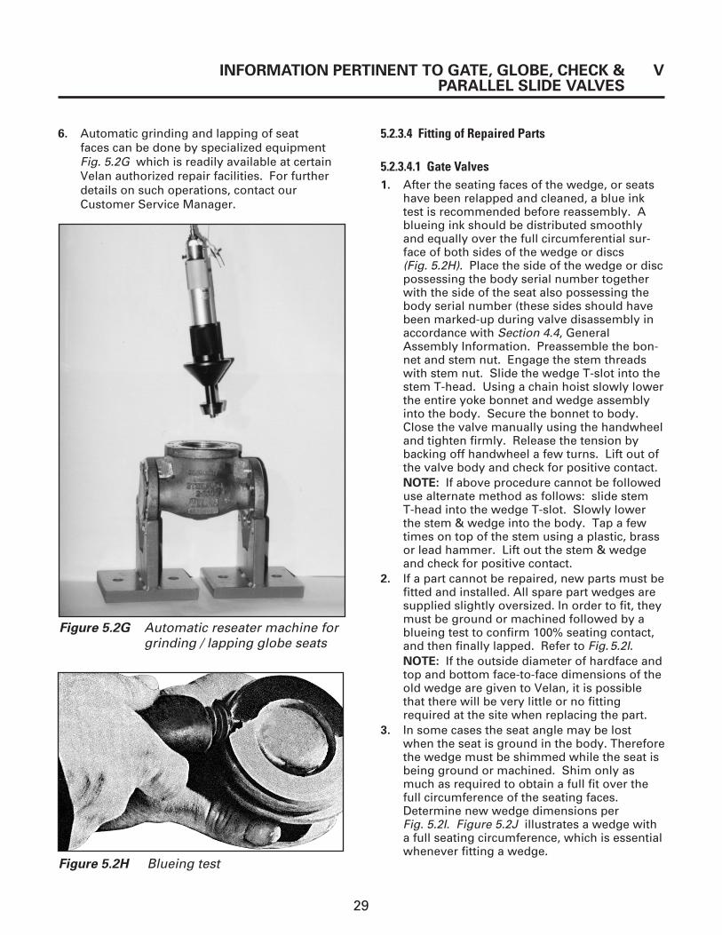
Figure 5.2H Blueing test
Figure 5.2G Automatic reseater machine forgrinding / lapping globe seats
6. Automatic grinding and lapping of seat faces can be done by specialized equipment Fig. 5.2G which is readily available at certainVelan authorized repair facilities. For furtherdetails on such operations, contact ourCustomer Service Manager.
5.2.3.4 Fitting of Repaired Parts
5.2.3.4.1 Gate Valves1. After the seating faces of the wedge, or seats
have been relapped and cleaned, a blue inktest is recommended before reassembly. Ablueing ink should be distributed smoothlyand equally over the full circumferential sur-face of both sides of the wedge or discs (Fig. 5.2H). Place the side of the wedge or discpossessing the body serial number togetherwith the side of the seat also possessing thebody serial number (these sides should havebeen marked-up during valve disassembly inaccordance with Section 4.4, GeneralAssembly Information. Preassemble the bon-net and stem nut. Engage the stem threadswith stem nut. Slide the wedge T-slot into thestem T-head. Using a chain hoist slowly lowerthe entire yoke bonnet and wedge assemblyinto the body. Secure the bonnet to body.Close the valve manually using the handwheeland tighten firmly. Release the tension bybacking off handwheel a few turns. Lift out ofthe valve body and check for positive contact.NOTE: If above procedure cannot be followeduse alternate method as follows: slide stem T-head into the wedge T-slot. Slowly lowerthe stem & wedge into the body. Tap a fewtimes on top of the stem using a plastic, brassor lead hammer. Lift out the stem & wedgeand check for positive contact.
2. If a part cannot be repaired, new parts must befitted and installed. All spare part wedges aresupplied slightly oversized. In order to fit, theymust be ground or machined followed by ablueing test to confirm 100% seating contact,and then finally lapped. Refer to Fig.5.2I. NOTE: If the outside diameter of hardface andtop and bottom face-to-face dimensions of theold wedge are given to Velan, it is possiblethat there will be very little or no fittingrequired at the site when replacing the part.
3. In some cases the seat angle may be lostwhen the seat is ground in the body. Thereforethe wedge must be shimmed while the seat isbeing ground or machined. Shim only asmuch as required to obtain a full fit over thefull circumference of the seating faces.Determine new wedge dimensions perFig. 5.2I. Figure 5.2J illustrates a wedge witha full seating circumference, which is essentialwhenever fitting a wedge.
INFORMATION PERTINENT TO GATE, GLOBE, CHECK & VPARALLEL SLIDE VALVES

30
Figure 5.2J Full seating circumference
1 2
3 4
B
t
d
4. When fitting a wedge, it is also important thatthe clearance between the wedge and thewedge guide slots be checked with a feelergauge at four locations, as shown in Fig. 5.2K.Ideally, the clearance on both sides should bethe same, however, a minimum clearance of0.005” (0.12 mm) at any position along thelength of the guide must be maintained.
5.2.3.4.2 Parallel Slide Valves
1. After the seating faces of the disc and seathave been relapped and cleaned with a suitable cleaning fluid such as acetone or alcohol, it is essential that the results be verified using a blue ink test, check for full circumferential contact. A light coating of blue ink should be distributed smoothly and equally over the seating diameter of the disc.To maintain the disc concentric with the seat,place shim stock at the bottom of the valvebody and lower the disc. Using a wood disc, a stud and nut and tension against the oppo-site seat, refer to Fig. 5.2L.
NOTE: Ensure that the same match markeddisc and seat are being checked.
2. Release bolt tension and remove stud and nut,lift out the disc and check for positive contact
Figure 5.2I Wedge dimensions
D
b
T
T = t -B × D + Bd
NOTE:
Seat dimensionBshould be transferred to wedge dimension b ± .005" (0.1 mm)
Top wedge dimension
Bottom wedge dimension
Serial number of body
Serial number of body
NOTE: Numbers refer to four locations to bechecked by filler gauge.
Figure 5.2K Clearance verification
V INFORMATION PERTINENT TO GATE, GLOBE, CHECK &PARALLEL SLIDE VALVES

31
INFORMATION PERTINENT TO GATE, GLOBE, CHECK & VPARALLEL SLIDE VALVES
(full seating circumference) Fig. 5.2M illus-trates a disc with a full seating circumference,which is essential whenever fitting a disc.
NOTE: Damages to the seat and disc exceed-ing 0.060” (1.5 mm) may require new part tobe replaced.
stud & nut
shim stock
wood disc
Figure 5.2L Parallel slide Preparation for blue ink test
Figure 5.2M Parallel slidefull seating circumference
Figure 5.2N Tapered disc– full seating circumference
5.2.3.4.3 Globe, Stop Check and Piston CheckValves
NOTE: Velan globe valves have, in the past,been designed with a flat style disc. In acontinuous effort to improve valve design,Velan has more recently adopted a tapereddisc as its standard.
1. After the seating faces of the disc and seathave been relapped and cleaned with a suit-able cleaning fluid such as acetone or alcohol,it is essential that the results be verified by ablue ink check. For full circumferential con-tact, a blue ink should be distributed smooth-ly and equally over the seating diameter of thedisc. Slowly lower the part into the body and
find the correct mating point of the faces.Fig.5.2N illustrates a disc with a full seatingcircumference, which is essential whenever fitting a disc.
2. When fitting the disc, it is also important that the body inside diameter be checked forsufficient clearance to allow the disc to movefreely up and down. We recommend a visualexamination of the body wall. Any grooves or scratches should be polished with a fineemery cloth, or buffing wheel 120-180 grit.
3. Verification of contact between the valve disc and the stem is made by a radius on the end of the valve stem and is designed togive center loading for the disc as closely aspossible. A hard thrust pad (Fig. 5.2O and5.2P), which can be found in some designs,will help prevent galling. On valves without a thrust pad, the bearing surface in the disc
Figure 5.2OTapered disc– thrust pad
Thrustpad
Figure 5.2PFlat style disc
Thrust pad

32
5.2.4 Seat Tightness– Closing Torques
Even with a brand new valve, seat tightness willonly be achieved when sufficient load has beenapplied to the wedge or disc. This load varies with
Hardface deposit
Figure 5.2QTapered disc–hardface deposit
V INFORMATION PERTINENT TO GATE, GLOBE, CHECK &
PARALLEL SLIDE VALVES
the pressure differential against which the valve has to be closed or opened.
As a guideline, Diagram 5.2A can be used to estimate the torque required to open or close avalve against a given differential pressure. Thetorque calculated is that torque which has to beapplied directly to the valve stem and does not take into account any mechanical advantage such as that achieved with a gear actuator, etc.
NOTE: Diagram 5.2A serves only as a generalguide line to determine approximate closing andopening torques required. It is not to be used ine.g. motor actuator, bevel gear or pneumatic actuator sizing.
CAUTION: The use of wheel wrenches,cheater bars, etc., is quite common.However, it must be emphasized that thesedevices should be used with discretion, andthen only to achieve approximately thetorque as calculated from Diagram 5.2A.
EXAMPLE:
Torque = (Pressure x K1) + K2
Type = GateSize = 10" (250 mm)Pressure = 1125 psiK1 = 0.41K2 = 26Torque = (1125 x 0.41) + 26
= 487 ft.lb.
NOTE: For API 603 valve use 50% of value calculated
Diagram 5.2A Closing torques
K 1gl
obe
K 1ga
te
Valve size
has a hardface depositon it (Fig.5.2Q).
If particles get caughtbetween the end ofthe valve stem and thedisc, the center of thestem could bedestroyed and the discwill not seat tightly.The contact surfacesof the stem and thedisc must be checkedfirst in leaky valves inorder to ensure thatthe disc-stem contactis in proper condition.

33
5.2.5 Backseat Repairs
1. The following valves are equipped with anintegral or screwed-in backseat in the bonnet(Fig.5.2R).
a) Screwed–in: All API 600 gate, globe, stop check and parallel slide valves
b) Integral: All API 603 gate, globe, stop checkand parallel slide valves
The above valves have a stem with a backseatshoulder. This should sit perfectly against the bonnet backseat to make a perfect seal. It is possible that this seal may leak due toscratches, pitting or other reasons. Thereforethis seal must be repaired by relapping themating faces.
2. Dismantle the valve in accordance withSection6.4.1 for gate valves, Section7.6.1 forglobe and stop check valves and Section 8.4.1for parallel slide valves
3. Place the bonnet and stem upside down asshown in Fig. 5.2S and insert two or threepacking rings in the packing chamber to serveas a guide for the centralizing of the stem tothe backseat.
Add a fine mixture of lapping compoundbetween the two mating faces. Gently rotatethe stem back and forth and occasionally liftthe stem slightly and rotate around backseatso that lapping will be distributed over a new area.
NOTE: On larger valves, the stem must besupported so that the weight of the stem doesnot cause a groove or galling on the backseat.
4. When the lapping procedure is finished, all lapping compound must be removed with a suitable cleaning fluid such as acetoneor alcohol.
5. Velan recommends that the lapping procedurebe verified for full contact by blueing one ofthe two faces. After verification, the surfacesmust be cleaned again.
Screwed in API 600
Integral API 603
Figure 5.2R Types of backseats
Figure 5.2S Backseat repair
INFORMATION PERTINENT TO GATE, GLOBE, CHECK & VPARALLEL SLIDE VALVES

34
BOLTING MATERIAL
THREAD SIZE B7, A-574, 630 B8, B8M
ft.lb. N.m ft.lb. N.m
3⁄8 –16 UNC 30 41 10 14
7⁄16 –14 UNC 45 61 15 20
1⁄2 –13 UNC 75 102 25 34
9⁄16 –12 UNC 105 142 35 48
5⁄8 –11 UNC 145 197 50 68
3⁄4 –10 UNC 255 346 85 115
7⁄8 – 9 UNC 405 549 135 183
1 – 8 UNC 615 834 205 278
11⁄8 –8 UN 900 1221 300 407
11⁄4 –8 UN 1270 1723 425 576
13⁄8 –8 UN 1725 2340 575 780
11⁄2 –8 UN 2280 3092 760 1031
15⁄8 – 8 UN 2935 3981 980 1329
13⁄4 – 8 UN 3715 5039 1240 1682
17⁄8 –8 UN 4615 6259 1540 2089
2 –8 UN 5650 7663 1880 2550
5.3 TORQUE VALUES – ACTUATOR, YOKE/BONNET BOLTING
The torque values shown in Table 5.3A are for all bolting other than bonnet retaining bolting or packing flange studs.
Table 5.3A Torque Values
Note :
(1) Torque tolerance ±10%
(2) For temperatures above 750°F (400°C) use 75% of the values.
(3) Maximum temperature for 630 is 650°F (345°C)
(4) Above Torque values are with the bolts lubricated.
V INFORMATION PERTINENT TO GATE, GLOBE, CHECK &
PARALLEL SLIDE VALVES
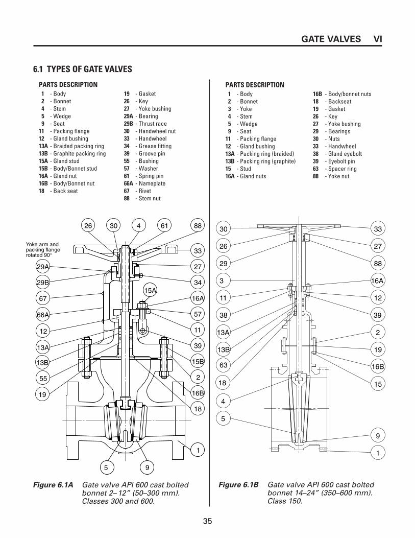
35
GATE VALVES VI
Figure 6.1A Gate valve API 600 cast boltedbonnet 2–12” (50–300 mm). Classes 300 and 600.
6.1 TYPES OF GATE VALVES
Yoke arm and packing flange rotated 90°
26 30 4 61 88
29A
29B
67
66A
12
13A
55
13B
19
34
16A
57
11
39
15B
2
16B
18
1
95
27
33
15A
Figure 6.1B Gate valve API 600 cast boltedbonnet 14–24” (350–600 mm).Class 150.
30
26
29
3
11
38
13A
13B
18
4
5
63
33
27
88
16A
12
39
2
19
15
9
1
16B
PARTS DESCRIPTION1 - Body 19 - Gasket2 - Bonnet 26 - Key4 - Stem 27 - Yoke bushing5 - Wedge 29A - Bearing9 - Seat 29B - Thrust race
11 - Packing flange 30 - Handwheel nut12 - Gland bushing 33 - Handwheel13A - Braided packing ring 34 - Grease fitting13B - Graphite packing ring 39 - Groove pin15A - Gland stud 55 - Bushing15B - Body/Bonnet stud 57 - Washer16A - Gland nut 61 - Spring pin16B - Body/Bonnet nut 66A - Nameplate18 - Back seat 67 - Rivet
88 - Stem nut
PARTS DESCRIPTION1 - Body 16B - Body/bonnet nuts2 - Bonnet 18 - Backseat3 - Yoke 19 - Gasket4 - Stem 26 - Key5 - Wedge 27 - Yoke bushing9 - Seat 29 - Bearings
11 - Packing flange 30 - Nuts12 - Gland bushing 33 - Handwheel13A - Packing ring (braided) 38 - Gland eyebolt13B - Packing ring (graphite) 39 - Eyebolt pin15 - Stud 63 - Spacer ring16A - Gland nuts 88 - Yoke nut

36
Figure 6.1C Gate valve API 600 cast bolted bonnet 26–28” (650–700 mm).Class 150.
6.1 TYPES OF GATE VALVES (CONT’D)
32
11
12
18
2
19
16C
16A
15C
15A
13A 13B
15B 16B
66
5
1
9
4
3
17
Rotated 90°for clarity
FLOW
Figure 6.1DGate valve API 603 stainless steel bolted bonnet, Classes 300, 600 and 900.1⁄2 –20” (15–500 mm) Class 150, 1⁄2 –12” (15–300mm) Class 300, integral seats,N/A in Classes 600/900.
VI GATE VALVES
NOTE: API 600 cast bolted bonnet gate valves, 30” and up (750 mm and up) are also equipped with gear operators.
PARTS DESCRIPTION1 - Body 15B - Body/Bonnet stud2 - Bonnet 15C - Yoke/actuator stud3 - Yoke 16A - Gland nut4 - Stem 16B - Body/Bonnet nut5 - Wedge 16C - Yoke/actuator nut9 - Seat 17 - HSH capscrew
11 - Packing flange 18 - Backseat12 - Gland bushing 19 - Gasket13A - Braided packing ring 32 - Gear operator13B - Graphite packing ring 66 - Nameplate15A - Gland stud
PARTS DESCRIPTION1 - Body 15B - Body/bonnet stud2 - Bonnet 16A - Gland nut4 - Stem 16B - Body/bonnet nut5 - Wedge 19 - Gasket
11 - Packing flange 27 - Yoke bushing12 - Gland bushing 33 - Handwheel13A - Packing rings 34 - Grease fitting13B - Packing rings 39 - Eye groove pin15A - Gland stud 61 - Spring pin
66A - Nameplate

37
33
61
30
16A
27
26
8834
12
13B
11
57
2
66A
67
13A
55
15B
19
5
4
18
39
15A
16B
1
9
GATE VALVES VI
6.2 GATE VALVE: EXPLODED VIEW
PARTS DESCRIPTION1 - Body2 - Bonnet4 - Stem5 - Wedge9 - Seat
11 - Packing flange12 - Gland bushing13A - Packing ring braided13B - Packing ring graphite15A - Gland stud15B - Body/Bonnet stud16A - Gland nut16B - Body/Bonnet nut18 - Backseat19 - Gasket26 - Key27 - Yoke bushing30 - Handwheel nut33 - Handwheel34 - Grease fitting39 - Groove pin55 - Bushing57 - Washer61 - Spring pin66A - Nameplate67 - Rivet88 - Stem nut

38
VI GATE VALVES
6.3 PARTIAL DISASSEMBLY – GASKET REPLACEMENT
Follow warning instructions in Section III beforebeginning disassembly. If valve is equipped with gear or motor actuator, see Appendix for disassembly of actuators.
NOTE: Numbers between brackets refer toitem numbers in exploded view.
1. Valve should be in partially open position.
2. If the valve is equipped with a leakoff pipe,disconnect it first. Leakoff pipes should be cutapproximately six inches from the bonnet.
3. Remove body/bonnet nuts (16B).
NOTE: If a valve has been in high temperatureservice for extensive periods of time, the nutsmay be seized to the studs (15B). Tight nutthreads can sometimes be loosened byapplying penetrating oil or applying heat tothe nut and working it free. As a last resort, a hacksaw, a cutting torch or a grinder can beused to cut the nut away from the stud.
4. Once all the nuts are removed, the entirebonnet assembly can be lifted from the valvebody. When lifting the bonnet assembly, careshould be taken to prevent the internal partsfrom disengaging from the stem. It is veryimportant to match–mark the body/bonnet andthe wedge (5) in order to maintain properorientation of these parts at reassembly.
5. Remove used gasket (19).
6. During inspection check the body/bonnetstuds for damage. Studs may have beendamaged when removing seized nuts. If studsare damaged, replace them.
7. Install new gasket. For corrugated steel withgraphite strips gasket and spiral woundgasket, body and bonnet flange surface mustbe completely cleaned and free of oil andgrease.
8. Line up the bonnet assembly with the bodyand lower onto the body.
9. Apply recommended lubricant (Table 4.3) tothe body/bonnet studs (15B) and nut flats(16B) then install body/bonnet nuts. Tightennuts in strict accordance with the body/bonnettorquing procedure Section 4.5, Table 4.5A
10. Mount packing flange nuts and torque down inaccordance with Table 5.1A.
11. Verify operation by cycling at least three timesfrom fully opened to fully closed position.
6.4 TOTAL DISASSEMBLY
6.4.1 Disassembly of Body/Bonnet and Wedge/Stem
Follow warning instructions in Section III beforebeginning disassembly. If valve is equipped withgear or motor actuator, see Appendix for disassem-bly of actuators.
1. Follow steps 1 through 6 in Section 6.3 PartialDisassembly - Gasket Replacement
2. If removing top works, follow steps 1 through 4in Section 6.4.2 Disassembly of Top Works
3. Loosen gland nuts (16A) and then carefully pullstem out through bottom of the bonnet.
4. Unscrew gland nuts from gland studs (15A).
5. Remove packing flange (11).
6. Only if required, remove groove pins (39) inorder to remove gland studs.
7. Unscrew the backseat (18) only if necessary.
8. Carefully remove old packing rings (13A,13B).Care should be taken not to scratch the walls ofthe packing chamber during the removal of thepacking rings.
6.4.2 Disassembly of Top Works
There are six basic styles of valve top works forVelan valves. Style 1 (no bearings), Style 2 (topandbottom sets of bearings) and Style 3 (top set ofbearings) apply to gate valves, (Fig. 6.4A). They areavailable for various sizes of gate valves as indicat-ed in Table 6.4A.
CAUTION: Do not tighten the body/bonnetnuts when the wedge is in the fully closed position.

39
GATE VALVES VI
The disassembly procedure for each of these stylesis described below.
NOTE: The handwheel nut may be secured byset screw or spring pin
1. The spring pin (61) is press fit. To remove the handwheel nut, It will be necessary to snap-offthe spring pin by holding firm the handwheeland applying sufficient force on the handwheelnut (counterclockwise) until the spring pinsnaps off.
2. Unscrew the handwheel nut (30). Remove thehandwheel (33) and the handwheel key (26).
3. After the tack weld is removed, unscrew the yoke bushing (27) from the bonnet (2). ForStyle 2 and Style 3, remove the top set ofbearings.
4. Unscrew the stem nut (88) from the stem (4).For Style 2, remove bottom set of bearings.
Tack weld
26 30 4 88 61 33
27
29B
29A 34
27
Tack weld
29A
26
27
29B
29A 29B
30 4 88 61 33
34
27
29A
29B
27
26 30 4 88 61 33
27
34
Tack weld
Figure 6.4A Top works styles–gate
Style 1
Style 2
Style 3
STYLE CLASS API 600 API 603
150 2 to 12” 1⁄2 to 12”300 2 to 8” 1⁄2 to 12”
1 600 2 to 4” N/A900 2 to 4” N/A1500 2 to 4” N/A150 14 to 24” 14 to 20”300 14 to 16” 14 to 16”
2 600 6 to 12” N/A900 6 to 8” N/A1500 6” N/A
3150 10 to 12” N/A300 10 to 12” N/A
Table 6.4A Top Works Styles–Gate
PARTS DESCRIPTION4 - Stem
26 - Key27 - Yoke bushing29A - Bearing29B - Thrust race (qty. 2)30 - Handwheel nut33 - Handwheel34 - Grease fitting61 - Spring pin88 - Stem nut

40
VI GATE VALVES
6.5 ASSEMBLYNOTE: Where * appears refer to lubricationtable in Section 4.3.
6.5.1 Top Works Assembly
1. *Apply new grease to threaded portion ofstem (4).
2. *For Style 2, grease and place bottom set ofbearings.
3. *Apply new grease to internal thread in stemnut (88).
4. Place stem nut.
5. *For Style 2 and Style 3 grease and install topset of bearings.
6. Screw in the yoke bushing (27). The yoke bush-ing must be tack-welded or staked to thebonnet (2).
7. Insert the handwheel key (26) in the stem nutand mount the handwheel (33).
8. Tighten handwheel nut (30) onto the stem nutand lock with set screw or spring pin (61) ifspring pin is used drill on new location. Inabsence of set screw and spring pin stakebetween handwheel and handwheel nut.
9. *Inject more new grease into the top worksthrough the grease fitting (34) on the side of thebonnet.
10. Verify operation by cycling at least once fromfully open to fully closed position.
6.5.2 Bonnet /Body Assembly
1. *Install new gasket (19). For corrugated steelwith graphite strips gasket and spiral woundgasket, body and bonnet flange surface must be completely cleaned and free of oil andgrease.
2. Lift and carefully lower the stem/wedge assembly.
3. Lift the bonnet using a chain block or comealong, and partially lower through the stem.Place the junk ring (packing spacer) and lantern ring if so equipped followed by the gland bushing and packing flange. Completelowering the bonnet. Care should be taken not to damage the gasket while lowering. Installtop works assembly in accordance with Section 6.5.1
4. *Apply recommended lubricant to thebody/bonnet studs (15B) and nut flats (16B)then install body bonnet nuts (16B). Tightennuts in strict accordance with the body/bonnettorquing procedure Section 4.5, Table 4.5A.
5. Mount packing flange nuts and torque down inaccordance with Table 5.1A.
6. Verify operation by cycling at least three timesfrom fully open to fully closed position.
CAUTION: Do not tighten the body/bonnetnuts when the wedge is in the fully closed position.
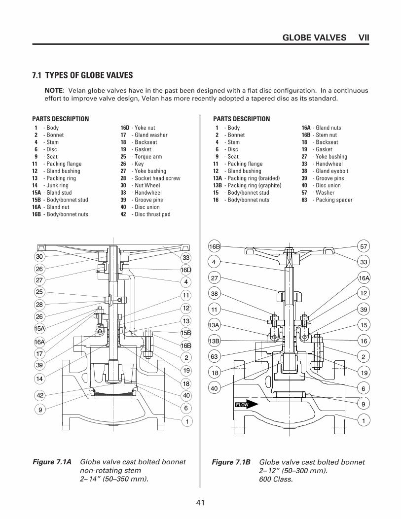
41
GLOBE VALVES VII
7.1 TYPES OF GLOBE VALVES
Figure 7.1B Globe valve cast bolted bonnet 2–12” (50–300 mm). 600 Class.
NOTE: Velan globe valves have in the past been designed with a flat disc configuration. In a continuous effort to improve valve design, Velan has more recently adopted a tapered disc as its standard.
30
26
27
25
26
28
15A
16A
17
39
14
33
16D
4
11
12
13
15B
16B
18
2
19
40
6
42
9
1
16B
4
27
38
11
13B
18
40
63
13A
57
33
16A
12
39
15
16
2
19
6
9
1
FLOW
Figure 7.1A Globe valve cast bolted bonnet non-rotating stem 2–14” (50–350 mm).
PARTS DESCRIPTION1 - Body 16A - Gland nuts2 - Bonnet 16B - Stem nut4 - Stem 18 - Backseat6 - Disc 19 - Gasket9 - Seat 27 - Yoke bushing
11 - Packing flange 33 - Handwheel12 - Gland bushing 38 - Gland eyebolt13A - Packing ring (braided) 39 - Groove pins13B - Packing ring (graphite) 40 - Disc union15 - Body/bonnet stud 57 - Washer16 - Body/bonnet nuts 63 - Packing spacer
PARTS DESCRIPTION1 - Body 16D - Yoke nut 2 - Bonnet 17 - Gland washer4 - Stem 18 - Backseat6 - Disc 19 - Gasket9 - Seat 25 - Torque arm
11 - Packing flange 26 - Key12 - Gland bushing 27 - Yoke bushing13 - Packing ring 28 - Socket head screw14 - Junk ring 30 - Nut Wheel15A - Gland stud 33 - Handwheel15B - Body/bonnet stud 39 - Groove pins16A - Gland nut 40 - Disc union16B - Body/bonnet nuts 42 - Disc thrust pad

42
VII GLOBE VALVES
Figure 7.1D Stop check valve cast bolted bonnet 2–14” (50–350 mm). The hardfaced seat is seal welded.
Figure 7.1C Globe valve cast bolted bonnet 14–16” (350–400 mm). 600 Class.
32
15C
26
11
12
2
19
16D
66
25
15B
39
13A
18
13B
38
16C
15A
4
40
41
9
16A
1
6
16B
FLOW
7.1 TYPES OF GLOBE VALVES (CONT’D)
PARTS DESCRIPTION1 - Body 16B - Gland nut2 - Bonnet 16C - Torque arm nut4 - Stem 16D - Yoke/actuator nut6 - Disc 18 - Backseat9 - Seat 19 - Gasket
11 - Packing flange 25 - Torque arm12 - Gland bushing 26 - Key13A - Packing ring (braided) 32 - Gear operator13B - Packing ring (graphite) 38 - Gland eyebolt15A - Body/bonnet stud 39 - Groove pin15B - Torque arm stud 40 - Disc union15C - Yoke/actuator stud 41 - Stem collar16A - Body/bonnet nut 66 - Name plate
PARTS DESCRIPTION1 - Body 16B - Body/bonnet nut2 - Bonnet 18 - Backseat3 - Yoke 19 - Gasket4 - Stem 27 - Yoke bushing6 - Disc 30 - Handwheel nut9 - Seat 33 - Handwheel
11 - Packing flange 39 - Groove pins12 - Gland bushing 40 - Disc union13B - Packing ring 42 - Disc thrust pad15B - Body/bonnet stud 46 - Spring15A - Gland stud 57 - Washer16A - Gland nut

43
Figure 7.1E Globe valve stainless bolted bonnet 1⁄2–12” (15–300 mm). Integral seats.
GLOBE VALVES VII
7.1 TYPES OF GLOBE VALVES (CONT’D)
PARTS DESCRIPTION1 - Body 16 - Lock nut2 - Bonnet 16A - Gland nut4 - Stem 16B - Nut6 - Disc 19 - Gasket
11 - Packing flange 27 - Yoke bushing12 - Gland bushing 33 - Handwheel13A - Packing ring 35 - Set screw15A - Gland stud 40 - Disc union15B - Body/bonnet stud 66A - Nameplate

44
13
30
55
33
57
38
11
16
2
12
16
19
18
4
40
156
91
7.2 GLOBE VALVE–ROTATING STEM: EXPLODED VIEW
PARTS DESCRIPTION
1 - Body2 - Bonnet4 - Stem6 - Disc9 - Seat
11 - Packing flange12 - Gland bushing13 - Packing ring15 - Body/bonnet16 - Nut18 - Backseat19 - Gasket30 - Handwheel nut33 - Handwheel38 - Gland stud40 - Disc union55 - Yoke bushing57 - Flat washer
VII GLOBE VALVES

45
1
15A
9
19
16A
34
88
26
27
3011
16B
57
15B
39
55
13
24
4
40
6
18
12
33
2
16A
17
25
GLOBE VALVES VII
7.3 GLOBE VALVE–NON-ROTATING STEM: EXPLODED VIEW
PARTS DESCRIPTION
1 - Body2 - Bonnet4 - Stem6 - Disc9 - Seat
11 - Packing flange12 - Gland bushing13 - Packing ring15A - Body/bonnet stud15B - Gland stud16A - Body/bonnet nut16B - Gland Nut17 - Cap screw18 - Backseat19 - Gasket24 - Key (torque arm)25 - Torque arm26 - Key 27 - Yoke bushing30 - Handwheel nut33 - Handwheel34 - Grease fitting39 - Grove pin40 - Disc union55 - Bushing57 - Flat washer88 - Stem nut
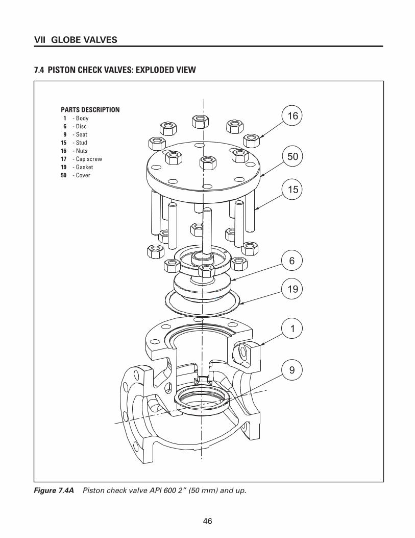
46
16
50
15
6
19
1
9
VII GLOBE VALVES
7.4 PISTON CHECK VALVES: EXPLODED VIEW
Figure 7.4A Piston check valve API 600 2” (50 mm) and up.
PARTS DESCRIPTION1 - Body6 - Disc9 - Seat
15 - Stud16 - Nuts17 - Cap screw19 - Gasket50 - Cover

47
GLOBE VALVES VII
7.5 PARTIAL DISASSEMBLY -GASKET REPLACEMENT
Follow warning instructions in Section III beforebeginning disassembly. If valve is equipped withgear or motor actuator, see appendix for disassem-bly of actuators.
1. Valve should be in partially open position.2. If the valve is equipped with a leakoff pipe,
disconnect it first. Leakoff pipes should beunscrewed or cut approximately six inchesfrom the bonnet.
3. Remove body/bonnet/cover nuts (16).NOTE: If a valve has been in high temperatureservice for extensive periods of time, the nutsmay be seized to the studs (15). Tight nutthreads can sometimes be loosened byapplying penetrating oil or applying heat to the nut and working it free. As a last resort, a hacksaw, a cutting torch or grinder can beused to cut the nut away from the stud.
4. Once all the nuts are removed, the entirebonnet assembly or cover can be lifted fromthe valve body. When lifting the bonnetassembly, care should be taken to prevent thedisc from becoming cocked and jam withinside the body core. It is very important tomatch–mark the body/bonnet and the disc (6)in order to maintain proper orientation of theseparts at reassembly.
5. Remove used gasket (19).6. During inspection check the body/bonnet studs
for damage. Studs may have been damagedwhen removing seized nuts. If studs are dam-aged, replace them.
7. Install new gasket. For corrugated steel withgraphite strips gasket and spiral wound gasket,body and bonnet flange surface must be com-pletely cleaned and free of oil and grease.
8. Line up the bonnet assembly with the body andlower onto the body.
9. Apply recommended lubricant (Table 4.3) tothe body/bonnet studs (15) and nut flats (16)then install body bonnet nuts. Tighten nuts instrict accordance with the body/bonnettorquing procedure of Section 4.5.
CAUTION: Do not tighten the body/bonnetnuts when the disc is in the fully closedposition.
10. Mount packing flange nuts and torque down inaccordance with Table 5.1B.
11. Verify operation by cycling at least three timesfrom fully opened to fully closed position.
7.6 TOTAL DISASSEMBLY OF GLOBE, STOP CHECK AND PISTON CHECK VALVES
7.6.1 Disassembly of Body/Bonnet andDisc/Stem/Union
Follow warning instructions in Section III beforebeginning disassembly. If valve is equipped withgear or motor actuator, see appendix fordisassembly of actuators.
NOTE: Numbers between brackets refer to itemnumbers in exploded view.
1. Valve should be in partially open position.2. If the valve is equipped with a leakoff pipe,
disconnect it first. Leakoff pipes should be cutapproximately six inches from the bonnet.
3. Remove body/bonnet/cover nuts (16).NOTE: If a valve has been in high temperatureservice for extensive periods of time, the nutsmay be seized to the studs (15). Tight nutthreads can sometimes be loosened byapplying penetrating oil or applying heat to the nut and working it free. As a last resort, a hacksaw, a cutting torch or grinder can beused to cut the nut away from the stud.
4. Once all the nuts are removed, the entirebonnet assembly or cover can be lifted from the valve body. When lifting the bonnet assem-bly, care should be taken to prevent the disc from becoming cocked and jam with the valvebody. It is very important to match–mark thebody/bonnet and the cover in order to maintainproper orientation of these parts at reassembly.
5. Remove used gasket (19).6. During inspection check the body/bonnet/cover
studs for damage. Studs may have been dam-aged when removing seized nuts. If studs aredamaged, replace them.
7. On the globe and needle disc valves the stemand disc will come out in one piece with thebonnet assembly. As for the stop check/pistoncheck valve, the disc must be removed onlyafter the bonnet/cover assembly has beenremoved from the body.
8. The connection between the stem and the discis made by the use of a disc union. To removethis connection, break the tack welds by using asaw or a grinder.

48
VII GLOBE VALVES
9. For the globe and needle disc valves, after thetack welds are removed, unscrew the discunion (40) from the disc. Check inside the discfor possible damages.
10. Remove top works refer to Section 7.6.2Disassembly of Top Works
11. Remove Torque arm (25) (non-rotating stem).There are four types of torque arms, see Fig. 7.6A:
Type I: One piece with bearing,Type II: One piece without bearing,Type III: Two piece with bearing,Type IV: Two piece without bearing.
a) Removal of Types I and II:
Loosen the cap screw (17C) and remove.Slide torque arm (25) up along stem andremove torque arm key (26A) from stem.Torque arm will not come off at this point,but you must make sure that the torque arm slides freely over the stem.
b) Removal of Types III and IV:
Loosen hex nuts (16D), pull torque armapart and remove torque arm key (26A)from stem. The torque arm will come totally off assembly at this point.
12. Loosen gland nuts (16) and then carefully pullstem out through the bottom of the bonnet.
13. Unscrew gland nuts from gland studs/eyebolt (15A).
14. Remove packing flange (11) from glandstuds/eyebolts.
15. Only if required, remove groove pins (39) inorder to remove gland studs/eyebolts.
16. Unscrew the backseat only if necessary (18).17. Carefully remove old packing rings (13). Care
should be taken not to scratch the walls of thepacking chamber during the removal of thepacking rings.
7.6.2 Disassembly of Top Works
There are six basic styles of valve top works forVelan valves. Style 2 (top and bottom sets ofbearings), Style 4 (no bearings) and Style 3 top setof bearings only shown in Fig.7.6B, apply to globevalves. They are available for various sizes of globevalves as indicated in Table 7.6A.
The disassembly procedure for each of these stylesis described below.
Disassembly Procedure:
Style 2 and 3
NOTE: The handwheel nut maybe secured byset screw or spring pin.
1. The spring pin (61) is press fit, to remove thehandwheel nut, it will be necessary to snap-off
Figure 7.5A Torque arm 4 types
TYPE I
TYPE III
TYPE II
TYPE IV
PARTS DESCRIPTION15D - Stud (torque arm)16D - Nut (torque arm)17C - Cap screw (torque arm)25 - Torque arm26A - Key (torque arm)29 - Bearing35 - Set screw

49
Table 7.6A Top works styles–Globe
Figure 7.6B Top works styles–Globe
Style 4
Style 2
Tack weld
the spring pin by holding firm the handwheeland applying sufficient force on the handwheelnut (counterclockwise) until the spring pinsnaps off.
2. Unscrew the handwheel nut (30). Remove thehandwheel (33) and the handwheel key (26).
3. After the tack weld is removed, unscrew theyoke bushing (27) from the bonnet. Remove thetop set of bearings. (for Style 2 and 3)
4. Unscrew the stem nut (88) from the stem (4).Remove bottom set of bearings. (for Style 2)
Style 41. Remove the handwheel nut (30) and hand-
wheel (33).2. After the tack weld is removed, unscrew the
yoke bushing (27) from the bonnet.
Tack weld
29A
26
27
29B
29A 29B
30 4 88 61 33
34
27
29A
29B
27
26 30 4 88 61 33
27
34
Tack weld
Style 3
STYLE CLASS WCB CAST
STAINLESS
150 12 to 14” N/A300 8 to 14” N/A
2 600 6 to 8” N/A900 2 to 4” N/A1500 2 to 4” N/A
150 8” N/A3
300 6” N/A
150 2 to 10” 1⁄2 to 6”300 2 to 6” 1⁄2 to 6”
4 600 2 to 4” N/A900 2 to 4” N/A1500 2 to 4” N/A
7.7 TOTAL DISASSEMBLY OF PISTON CHECK VALVE
1. Remove body/cover nuts (16).
2. Once all the nuts are removed, the cover (50)and gasket can be lifted from the valve bodyas shown in Fig. 7.5A.
3. Lift the disc (6) and spring option (46) from thevalve body.
GLOBE VALVES VII
QUANTITYPARTS DESCRIPTION STYLE
2 3 44 - Stem 1 1 1
26 - Key 1 1 127 - Yoke bushing 1 1 129A - Bearing 2 1 029B - Thrust race 4 2 030 - Handwheel nut 1 1 133 - Handwheel 1 1 134 - Grease fitting 1 1 157 - Flat washer 1 1 161 - Spring pin 1 1 188 - Stem nut 1 1 1
50
7.8 ASSEMBLYNOTE: Where *appears refer to lubricationtable in Section 4.3.
7.8.1 Top Work Assembly
1. *Apply new grease to threaded portion ofstem (4).
2. *For Style 2, grease and place bottom set of bearings.
3. *Apply new grease to internal thread in stem nut (88).
4. Place stem nut.
5. *For Style 2 and 3 grease and install top set of bearings.6. Screw in the yoke bushing (27).The yoke bushing must be tack-welded to thebonnet (2), or staked.
7. Insert the handwheel key (26) in the stem nutand mount the handwheel (33).
8. Tighten handwheel nut (30) onto the stem nutand lock with set screw or spring pin (61). Ifspring pin is used, drill on new location. Inabsence of set screw and spring pin stakebetween handwheel and handwheel nut.
9. *Inject more new grease into the top worksthrough the grease fitting (34) on the side ofthe bonnet.
10. Verify operation by cycling at least once fromfully open to fully closed position.
7.8.2 Disc and Bonnet/Body Assembly
1. Insert disc into valve body. Insert spring intodisc if so equipped.
Install small thrust pad into disc. Install stem in disc and tighten down with disc union.Check if disc can be rotated. If disc can berocked, it is correctly installed on stem. Therocking will allow the disc to self-align itself to the seat.
2. Tack weld disc union to disc in three or fourplaces. Check again to see if the disc can rockafter tack welding has cooled.
3. *Install new gasket. For corrugated steel withgraphite strips gasket and spiral wound gasket,body and bonnet flange surface must be com-pletely cleaned and free of oil and grease.
4. Lift the stem/disc assembly and carefully lowerinto the body.
NOTE: for 8” valves and up, a chain block orcome along should be used. Mount the torquearm (25), wrap a nylon sling around the stemjust below the torque arm. Lift and carefullylower the stem/disc assembly
5. Lift the bonnet using a chain block or comealong, and partially lower through the stem.Place the junk ring (packing spacer) and lantern ring, if so equipped, followed by the gland bushing, packing flange and torque arm.Completely lower the bonnet. Care should betaken not to damage the gasket while lowering.Install Top Works Assembly in accordance withSection 7.8.1
6. *Apply recommended lubricant to thebody/bonnet studs (15) and nut flats (16) theninstall body/bonnet nuts. Tighten nuts in strictaccordance with the body/bonnet torquingprocedure, Section 4.5 Table 4.5A.
7. Mount packing flange nuts and torque down inaccordance with Table 5.1B.
8. Verify operation by cycling at least three timesfrom fully open to fully closed position.
CAUTION: Do not tighten the body/bonnetnuts when the disc is in the fully closedposition.
VII GLOBE VALVES

51
PARALLEL SLIDE VALVES VIII
4935
1725
426
45
43
15
60
16
46
1
9
7
8.1 PARALLEL SLIDE VALVE: EXPLODED VIEW
PARTS DESCRIPTION1 - Body4 - Stem7 - Slide discs9 - Seat
15 - Stud16 - Nut17 - Torque arm bolting25 - Torque arm26 - Key 35 - Limiter set screw43 - Slide disc carrier45 - Slide disc retainers46 - Spring49 - Stroke limiter60 - Tab lock washer

52
VIII PARALLEL SLIDE VALVES
19
4
4346
7
15
16
6045
454
9
Gap "B" (Carrier/Disc)
Gap "C" (Min. 0.005" (0.13 mm)(Retainer/Disc)
Gap "A" (Retainer/Disc)
43
7
15
16
60
8.2 PARALLEL SLIDE VALVE STEM/DISC CARRIER/DISC ASSEMBLY
PARTS DESCRIPTION1 - Body4 - Stem7 - Slide discs9 - Seat
15 - Stud16 - Nut43 - Slide disc carrier45 - Slide disc retainers46 - Spring60 - Tab lock washer
-ALWAYS MAINTAIN MINIMUM 0.005”(0.13 mm) AT GAP "C"
-GAP "A" MUST ALWAYS BE GREATER THAN GAP "B"NOTE:
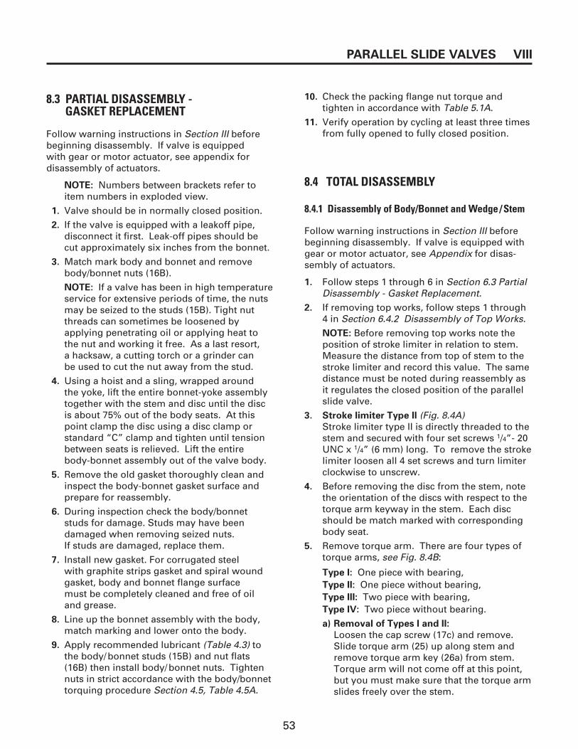
53
PARALLEL SLIDE VALVES VIII
8.3 PARTIAL DISASSEMBLY - GASKET REPLACEMENT
Follow warning instructions in Section III beforebeginning disassembly. If valve is equipped with gear or motor actuator, see appendix for disassembly of actuators.
NOTE: Numbers between brackets refer toitem numbers in exploded view.
1. Valve should be in normally closed position.
2. If the valve is equipped with a leakoff pipe,disconnect it first. Leak-off pipes should be cut approximately six inches from the bonnet.
3. Match mark body and bonnet and removebody/bonnet nuts (16B).
NOTE: If a valve has been in high temperatureservice for extensive periods of time, the nutsmay be seized to the studs (15B). Tight nutthreads can sometimes be loosened byapplying penetrating oil or applying heat tothe nut and working it free. As a last resort, a hacksaw, a cutting torch or a grinder can be used to cut the nut away from the stud.
4. Using a hoist and a sling, wrapped around the yoke, lift the entire bonnet-yoke assemblytogether with the stem and disc until the discis about 75% out of the body seats. At thispoint clamp the disc using a disc clamp orstandard “C” clamp and tighten until tensionbetween seats is relieved. Lift the entire body-bonnet assembly out of the valve body.
5. Remove the old gasket thoroughly clean andinspect the body-bonnet gasket surface andprepare for reassembly.
6. During inspection check the body/bonnetstuds for damage. Studs may have beendamaged when removing seized nuts. If studs are damaged, replace them.
7. Install new gasket. For corrugated steel with graphite strips gasket and spiral woundgasket, body and bonnet flange surface must be completely cleaned and free of oil and grease.
8. Line up the bonnet assembly with the body,match marking and lower onto the body.
9. Apply recommended lubricant (Table 4.3) tothe body/bonnet studs (15B) and nut flats(16B) then install body/bonnet nuts. Tightennuts in strict accordance with the body/bonnettorquing procedure Section 4.5, Table 4.5A.
10. Check the packing flange nut torque and tighten in accordance with Table 5.1A.
11. Verify operation by cycling at least three timesfrom fully opened to fully closed position.
8.4 TOTAL DISASSEMBLY
8.4.1 Disassembly of Body/Bonnet and Wedge/Stem
Follow warning instructions in Section III beforebeginning disassembly. If valve is equipped withgear or motor actuator, see Appendix for disas-sembly of actuators.
1. Follow steps 1 through 6 in Section 6.3 PartialDisassembly - Gasket Replacement.
2. If removing top works, follow steps 1 through4 in Section 6.4.2 Disassembly of Top Works.
NOTE: Before removing top works note theposition of stroke limiter in relation to stem.Measure the distance from top of stem to thestroke limiter and record this value. The samedistance must be noted during reassembly as it regulates the closed position of the parallelslide valve.
3. Stroke limiter Type II (Fig. 8.4A)Stroke limiter type II is directly threaded to thestem and secured with four set screws 1/4”- 20UNC x 1/4” (6 mm) long. To remove the strokelimiter loosen all 4 set screws and turn limiterclockwise to unscrew.
4. Before removing the disc from the stem, notethe orientation of the discs with respect to thetorque arm keyway in the stem. Each discshould be match marked with correspondingbody seat.
5. Remove torque arm. There are four types oftorque arms, see Fig. 8.4B:
Type I: One piece with bearing,Type II: One piece without bearing,Type III: Two piece with bearing,Type IV: Two piece without bearing.
a) Removal of Types I and II:
Loosen the cap screw (17c) and remove.Slide torque arm (25) up along stem andremove torque arm key (26a) from stem.Torque arm will not come off at this point,but you must make sure that the torque armslides freely over the stem.

54
VIII PARALLEL SLIDE VALVES
b) Removal of Types III and IV:
Loosen hex nuts (16D), pull torque armapart and remove torque arm key (26A) from stem. The torque arm will come totally off assembly at this point.
6. Loosen gland nuts (16A) and then carefullypull stem out through the bottom of the bonnet.
7. Unscrew gland nuts from gland studs (15A).8. Remove packing flange (11).9. Only if required, remove groove pins (39) in
order to remove gland studs.
10. Unscrew the backseat (18) only if necessary.
11. Carefully remove old packing rings (13A, 13B).Care should be taken not to scratch the wallsof the packing chamber during the removal ofthe packing rings.
8.4.2 Disassembly of Top Works
There are six basic styles of valve top works forVelan valves. Style 5 (top set of bearings and 1thrust race at the bottom), Style 6 (topand bottomthrust race).
The disassembly procedure for each of thesestyles is described below.
1. Before removing stroke limiter (49) take noteof the stroke limiter position in relation to the valve stem as described in Section 6.4.1step 2 and 3 .
NOTE: The handwheel nut may be secured byset screw or spring pin.
2. The spring pin (61) is press fit. to remove thehandwheel nut, it will be necessary to snap-offthe spring pin by holding firm the handwheeland applying sufficient force on the handwheelnut (counterclockwise) until the spring pinsnaps off. Unscrew the handwheel nut (30)Remove the handwheel (33) and the hand-wheel key (26).
3. After the tack weld is removed, unscrew theyoke bushing (27) from the bonnet (2). ForStyle 5, remove the top set of bearings. ForStyle 6, remove top thrust race.
4. Unscrew the stem nut (88) from the stem (4).For Style 5 and 6, remove bottom thrust race.
Table 8.4A Top Works Styles–Parallel Slide
STYLE CLASS SIZES
1 1500 1 - 2”5 300 10 - 12”6 300 3 - 8”
33
35A
26B
17D
88
49
35
30
28
34
Figure 8.4A Stroke limiter Type II
PARTS DESCRIPTION03 - Yoke04 - Stem17D - HSH cap screw26A - Key28 - Housing cover30 - Handwheel nut31 - Lock washer33 - Handwheel34 - Grease fitting35 - Set screw35A - Set screw49 - Stroke limiter88 - Stem nut

55
Tack weld
26 30 4 88 61 33
27
34
27
Style 6
Style 5Style 1
PARALLEL SLIDE VALVES VIII
Tack weld
26 30 4 88 61 33
27
29B
29A 34
27
29A
29B
27
26 30 4 88 61 33
27
3429B
Tack weld
QUANTITYPARTS DESCRIPTION STYLE
1 5 64 - Stem 1 1 1
26 - Key 1 1 127 - Yoke bushing 1 1 129A - Bearing 1 1 029B - Thrust race 2 3 030 - Handwheel nut 1 1 133 - Handwheel 1 1 134 - Grease fitting 1 1 157 - Flat washer 1 1 161 - Spring pin 1 1 188 - Stem nut 1 1 1
Figure 8.4B Torque arm 4 types
TYPE I
TYPE III
TYPE II
TYPE IV
PARTS DESCRIPTION
15D - Stud (torque arm)16D - Nut (torque arm)17C - Cap screw (torque arm)25 - Torque arm26A - Key (torque arm)29 - Bearing35 - Set screw
Figure 8.4C Top works style - Parallel Slide

56
8.5 ASSEMBLYNOTE: Where * appears refer to lubricationtable in Section 4.3.
8.5.1 Top works assembly1. *Apply new grease to threaded portion of
stem (4).2. *For Style 5 and 6, grease and place bottom
thrust race.3. *Apply new grease to internal thread in stem
nut (88). 4. Place stem nut.5. *For Style 5 grease and install top set of
bearings. For Style 6 place top thrust race.6. Screw in the yoke bushing (27). The yoke
bushing must be tack-welded to the bonnet (2)or staked.
7. Insert the handwheel key (26) in the stem nutand mount the handwheel (33).
8. Tighten handwheel nut (30) onto the stem nutand lock with set screw or spring pin (61) ifspring pin is used drill on new location. Inabsence of set screw and spring pin stakebetween handwheel and handwheel nut.
9. *Inject more new grease into the top worksthrough the grease fitting (34) on the side ofthe bonnet.
10. Mount stroke limiter and position as notedduring disassembly, and secure with setscrews.IMPORTANT: The position of the stroke limitermust be the same as that noted during valvedisassembly. If the original position has notbeen noted, the following procedure should beused:a) Open valve fully to its back seated position
and mark up with a pen or marker.b) Verify applicable valve project drawing for
valve “loft” (stroke). Measure from markedup open position and draw a line (mark up)indicating valve closed position.
c) Close the valve to its marked up closed position and readjust stroke limiter.
For Motor Actuated Valves: It is necessary toreadjust open/close limit switch. Open limitswitch should be adjusted as a rule of thumb(6 mm) off back seat. Closed limit switchshould be adjusted at already establishedclosed position.
11. Verify operation by cycling at least once fromfully open to fully closed position.
8.5.2 Bonnet /Body and Disc/Stem Assembly1. Thread the stem (4) in the disc carrier (43) and
line up with bolt holes. Place one disc half (7)and wave spring (46) into the disc carrier followed by 2nd disc half. Using a disc clampFig. 8.4A or standard “C” clamp squeeze thetwo disc halves together. Install disc retainerplates (45) into the disc groove (per side) andline up bolt holes. Install two retainer studs orhex. bolts (56A) connecting the retainer platesdisc carrier and stem and tighten firmly.
2. Partially lower stem/disc assembly into thebody seats. Remove the disc clamp, and completely lower into the seats.NOTE: For values 8” and up it may be necessary to mount the torque arm (25) toenable placing a sling under the torque arm and around the stem for lifting and loweringpurposes.
3. Check disc/disc carrier/retainer plate for propergap allowance refer to Fig. 8.5B
4. Install new gasket (19). For corrugated steelwith graphite strips gasket and spiral woundgasket, body and bonnet flange surface must be completely cleaned and free of oil andgrease.
5. Apply recommended lubricant to the body/bonnet studs (15B) and nut flats (16B) theninstall body bonnet nuts. Tighten nuts in strictaccordance with the body/bonnet torquing procedure Section 4.5, Table 4.5A.
6. Lift the bonnet using a chain block or comealong, and partially lower through the stem.Place the junk ring (packing spacer) and lantern ring if so equipped followed by the gland bushing, packing flange and torque arm.Completely lower the bonnet. Care should betaken not to damage the gasket while lower-ing. Install top works assembly in accordancewith Section 6.5.1.
7. Mount packing flange nuts and torque down inaccordance with Table 5.1A.
8. Verify operation by cycling at least three timesfrom fully open to fully closed position.
CAUTION: To prevent close torque switchtrip out, stroke limiter must be backed off by1/8–1/4” (3–6 mm) and set screw secured.
VIII INFORMATION PERTINENT TO GATE, GLOBE, CHECK &PARALLEL SLIDE VALVES

57
PARALLEL SLIDE VALVES VIII
Figure 8.5A Parallel slide disc clamp
454
9
Gap "B" (Carrier/Disc)
Gap "C" (Min. 0.005" (0.13 mm)(Retainer/Disc)
Gap "A" (Retainer/Disc)
43
7
15
16
60
Figure 8.5B Check for gap disc / disc carrierand retainer plate
PARTS DESCRIPTION
1 - Arm2 - Adjusted screw3 - Cross member4 - Pivot pin
PARTS DESCRIPTION4 - Stem7 - Slide discs9 - Seat
15 - Stud16 - Nut43 - Slide disc carrier45 - Slide disc retainers60 - Tab lock washer

58
IX SWING CHECK, TILTING DISC, TESTABLE & BALL CHECK VALVES
Figure 9.1B Swing check valve API 603 stainless bolted cover 2–24” (50-600 mm)integral seats.
Figure 9.1A Swing check valve API 600 cast bolted cover 2–12” (50-300 mm).The hardfaced seat is seal welded.
9.1 TYPES OF SWING CHECK VALVES
19
15 16 50
51
58
56
54
5789 16A
60
57B
54
1
FLOW
16 5054 15
19
51
54
60
156 57B
585789 16A
FLOW
Manufacturer’s option
Hinge pin arrangement
Hinge pin arrangement
Manufacturer’s option
PARTS DESCRIPTION
1 - Body8 - Disc9 - Seat
15 - Stud16 - Nuts16A - Disc nut19 - Gasket50 - Cover51 - Hanger arm54 - Hinge pin56 - Hex hd cap screw57 - Washer57B - Hinge pin washer58 - Cotter pin60 - Tab washer
PARTS DESCRIPTION
1 - Body8 - Disc9 - Seat
15 - Stud16 - Nuts16A - Disc nut19 - Gasket50 - Cover51 - Hanger arm54 - Hinge pin56 - Hex hd cap screw57 - Washer57B - Hinge pin washer58 - Cotter pin60 - Tab washer

59
SWING CHECK, TILTING DISC, TESTABLE & BALL CHECK VALVES IX
Figure 9.1C Bolted Cover Ball Check Valve
9.1 TYPES OF SWING CHECK VALVES
1
19
73B
6016
15
8
50
61
74 72 73A35
Figure 9.1D Bolted Cover Testable Swing Check Valve
9
19
51
54
50
58
1
16A
60
8
16
15
PARTS DESCRIPTION1 - Body8 - Disc9 - Seat
15 - Stud16 - Nuts16A - Disc nut19 - Gasket50 - Cover51 - Hanger arm54 - Hinge pin58 - Cotter pin60 - Tab washer
PARTS DESCRIPTION
1 - Body5 - Ball
15 - Stud16 - Nuts19 - Gasket35 - Set screws50 - Cover
60 - Tab lock washers61 - Dowel pin72 - Soft seat73A - Soft seat retainer73B - Check ball cage74 - O-ring

60
IX SWING CHECK, TILTING DISC, TESTABLE & BALL CHECK VALVES
9.2 SWING CHECK VALVE: EXPLODED VIEW
16
56
19
50
54
16A
57
8
9
51
1
15
PARTS DESCRIPTION1 - Body8 - Disc9 - Seat
15 - Body/bonnet stud16 - Body/bonnet nut16A - Disc nut19 - Gasket50 - Cover51 - Hanger arm54 - Hinge pin56 - Hex hd cap screw57 - Flat washer

61
SWING CHECK, TILTING DISC, TESTABLE & BALL CHECK VALVES IX
9.3 TYPE OF TILTING DISC CHECK VALVE
1615
50
9
8
50
1
19
54
56
31
61
52
548
Figure 9.3C Tilting disc check valve 21/2–12” (65–300 mm).The hardfaced seat is sealwelded.
PARTS DESCRIPTION1 - Body8 - Disc9 - Seat
15 - Body/bonnet stud16 - Body/bonnet nut31 - Lock bracket19 - Gasket50 - Cover52 - Pin bracket54 - Hinge pin56 - Hex hd cap screw61 - Dowel pin

62
9.3.1 Tilting Disc Closure Kit Fit-up(refer to Fig. 9.3D)
The tilting disc (08), swing on the hinge pin (54)which is stationary. The hinge pin is held in placeby the hinge pin block (18) which is bolted to thebody (01) by a hex bolt (56) and secured with lockwasher (60). The hinge pin block hole diameter isoversized by approximately 1/16” (1.6 mm) to allowdisc adjustment with body seat. Once adjusted, thehinge block, the hinge pin and the body hinge knoba hole is drilled for the dowel pin (17). This is doneat assembly and should not be required in the fieldunless new spare part hinge block, hinge pin and ortilting disc is being replaced. If new parts must bereplaced follow tilting disc adjustment procedureSection 9.7.2 a) and b).
9.4 PARTIAL DISASSEMBLY - GASKET REPLACEMENTSWING CHECK AND TILTING DISC VALVES
Follow warning instructions in Section III beforebeginning disassembly.
NOTE: Numbers between brackets refer toitem numbers in exploded view.
1. Remove body–cover nuts (16).
2. Once all the nuts are removed, the cover (50) and gasket (19) can be lifted from the valve body.
3. Install new spiral wound flexitalic gasket.
NOTE: If it is a soft iron gasket, apply lubrication (a light coat of oil).
4. Line up the cover with the body (1) and loweronto the body.
5. Apply the recommended lubricant to thebody–cover studs and then install thebody–cover nuts. Tighten in strict accordancewith Section 4.5, Body /Cover TorquingProcedure.
9.5 TOTAL DISASSEMBLY - TILTING DISC
Follow warning instructions in Section III beforebeginning disassembly.
Further to steps 1 and 2 in Section9.4 PartialDisassembly, the following steps illustrate total disassembly of the tilting disc valve.
IX SWING CHECK, TILTING DISC, TESTABLE & BALL CHECK VALVES
1. The valve is now ready for inspection. At thispoint in the disassembly procedure, inspect the rotation of the disc (8) on the hinge pin(54) and the alignment between the disc andthe seat (9). Ensure that the disc has freemovement, is not binding and is not beingrestricted by any internal part.
2. After inspecting all points mentioned above,remove all internal parts by unfolding the lock washers (60) around the hex hd bolt (56)in body.
3. After hex HD bolts have been removed, theinternal assembly can be removed from thebody. Fig. 9.3D shows internal assembly.
NOTE: It is important to match-mark left andright side of hinge pin, hinge block and body,as these must go back in the same order atreassembly.
9.6 DETAILED MAINTENANCETILTING DISC VALVE
9.6.1 Body/Cover (Gasket) Leakage
To maintain the tightness of a factory-testedbolted bonnet valve, it is essential to applysufficient bolt tension at all times by having theproper torque on the nuts or cap screws. Theoriginal torque might be lost due to vibration,relaxation of material caused by frequent temper-ature and pressure fluctuations, or by creep inhigh temperature applications. Gasket bolt tensionshould be checked at approximately one-yearintervals (see Section 5.2.3 Gasket boltsretorquing procedure).
NOTE: Standard gasket material is corrugatedsteel with graphite in the channels or spiralwound gasket.
For alternate gasket materials contact our servicedepartment.
9.6.2 Seat Leakage - Tilting Disc
9.6.2.1 Tilting Disc Repairs - General
If minor damage to disc seating surface is noted, itshould be lapped out using a seat ring having anangle of 22º. Place (smear) medium grit lappingcompound on seat ring and disc surface and rockseat ring in an up and down motion, with lightpressure applied against the disc. If major repairs

63
become necessary, the disc should be repaired bymachining. No more than 0.015” (0.4 mm) shouldbe removed.
NOTE: Disc seating surface is of a SphericalRadius.
9.6.2.2 Tilting Disc Seat Repairs - General
If minor damage to seating surface is noted, up to 0.005” (0.08 mm), it should be lapped out by using original disc. Place (smear) 80-100 medium grit lapping compound on seat and discsurface. Reinstall disc and move back and forth,(open-close) slightly while applying light pressureagainst seat. Complete lapping with fine compound 220 or higher.
If major seat damage is noted, no greater than0.015” (0.38 mm), it should be repaired using acone shaped seat guided disc for hand or machineoperation. Use stick on abrasive paper 60-120 grit to remove damage and 220 grit or higher forpolishing. If stick on abrasive paper is not available use lapping compound similar grit.
NOTE: Tilting disc seat angle is 22º. A coneshaped disc or ring for hand or machine lapping may have to be fabricated with sameseat angle.
9.6.2.3 Bearing Blue or Developer Test(Removal of disc is required)
Prior to reassembly, apply light coating of bearingblue or dye developer on the disc seating surface.Install the disc with hinge pin. Place the disc intothe valve body and on the body knob hinge pinlocation. With one hand keep the disc from con-tacting the seat. With the other hand insert thedowel pins and hinge block. Secure the hingeblock with bolts. Gently release the disc and pushfirmly against the seat. Remove the hinge blockbolts and remove the disc. Verify for 100% seatingcontact.
Alternate Test Using Feeler Gauge:
Reassemble and install disc as described above.Using a 0.001” (0.025 mm) feeler gauge, with onehand press the disc against the seat, with the otherhand check between the disc and seat all aroundthe 360º degrees seating circumference. If thefeeler gauge does not penetrate between seats,the disc is properly aligned with 360º degrees circumferential contact.
9.7 ASSEMBLY - TILTING DISC
9.7.1 Disc Assembly Fit-up
1. After completion of all repair work and successful blue ink or dye developer check.Clean the valve and all components thorough-ly. Following match marks, insert hinge pin(54) into disc (80) lower the disc with hingepin into the body (1) and onto the body knobhinge pin location. Insert dowel pins (17) inthe holes provided. Install the hinge pin block(18) on top of hinge pin and body knob. Placelock washers (60) and secure tighten withhinge pin bolts (56) use appropriate torquevalue see torque Table 5.3A. Swing the discopen/close a few times to ensure disc freemovement (no interference). Replace with anew gasket (19) and cover (50). Install bodycover bolts and torque to appropriate valve inaccordance with bolt torque procedure Section4.5 Table 4.5A.
9.7.2 Tilting Disc Adjustment Procedure
1. This procedure is to be used whenever replacing with new spare part tilting disc (8),hinge pin (54), hinge pin block (18) or bodyseat (9).
a) If using new hinge pin and or hinge pinblock, the disc must be aligned manually bypressing the disc against the body seat withone hand and then tighten hinge pin blockwith hinge pin bolts. This will keep the discaligned. Drill new alignment location holes(dowel pin holes) (one per side).
NOTE: The new location holes must be awayform the existing hole in the body knob.
b) If using new tilting disc and or body seat,disc alignment should be checked usingexisting down pin holes. If off align use thesame adjustment procedure as describedabove in paragraph a).
SWING CHECK, TILTING DISC, TESTABLE & BALL CHECK VALVES IX
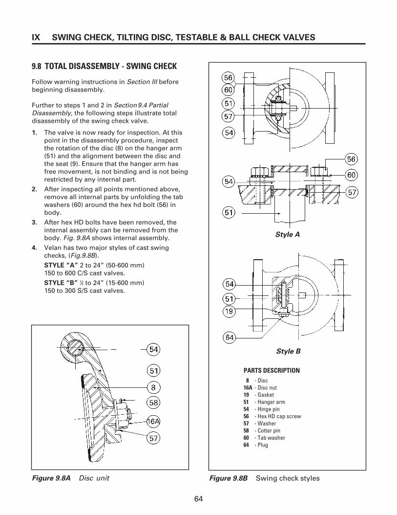
64
IX SWING CHECK, TILTING DISC, TESTABLE & BALL CHECK VALVES
9.8 TOTAL DISASSEMBLY - SWING CHECK
Follow warning instructions in Section III beforebeginning disassembly.
Further to steps 1 and 2 in Section9.4 PartialDisassembly, the following steps illustrate totaldisassembly of the swing check valve.
1. The valve is now ready for inspection. At thispoint in the disassembly procedure, inspectthe rotation of the disc (8) on the hanger arm(51) and the alignment between the disc andthe seat (9). Ensure that the hanger arm hasfree movement, is not binding and is not beingrestricted by any internal part.
2. After inspecting all points mentioned above,remove all internal parts by unfolding the tabwashers (60) around the hex hd bolt (56) inbody.
3. After hex HD bolts have been removed, theinternal assembly can be removed from thebody. Fig. 9.8A shows internal assembly.
4. Velan has two major styles of cast swingchecks, (Fig.9.8B).
STYLE “A” 2 to 24” (50-600 mm)150 to 600 C/S cast valves.
STYLE “B” 1⁄2 to 24” (15-600 mm)150 to 300 S/S cast valves.
Style A
Style B
PARTS DESCRIPTION8 - Disc
16A - Disc nut19 - Gasket51 - Hanger arm54 - Hinge pin56 - Hex HD cap screw57 - Washer58 - Cotter pin60 - Tab washer64 - Plug
Figure 9.8B Swing check stylesFigure 9.8A Disc unit

65
SWING CHECK, TILTING DISC, TESTABLE & BALL CHECK VALVES IX
9.9 DETAILED MAINTENANCESWING CHECK
9.9.1 Body/Cover (Gasket) Leakage
To maintain the tightness of a factory-testedbolted bonnet valve, it is essential to applysufficient bolt tension at all times by having theproper torque on the nuts or cap screws. Theoriginal torque might be lost due to vibration,relaxation of material caused by frequent tempera-ture and pressure fluctuations, or by creep in hightemperature applications. Gasket bolt tensionshould be checked at approximately one-yearintervals (see Section 2.9 Recheck For Bolt Tightness procedure).
NOTE: Standard gasket material is corrugatedsteel with graphite in the channels or spiralwound gasket.
For alternate gasket materials contact our servicedepartment.
9.9.2 Seat Leakage
9.9.2.1 Disc Repairs
1. Disassemble the valve as described inSection 9.6, and inspect the disc and seat forscratches, pitting marks or other damage.
2. If the seating face of the disc is scratched, itmust be lapped. Slight pitting, grooving, orindentations no deeper than 0.005” (0.1 mm)can be removed by lapping. If defects cannotbe corrected by lapping, the disc can beground and/or machined. Velan recommendsthat no more than 0.031” (0.80 mm) beremoved. After grinding is completed, lap the disc.
3. For the lapping, a flat plate (preferably madeof cast iron) should be used. An abrasive lap-ping compound should be mixed togetherwith olive oil and evenly distributed over theplate as shown in Fig. 9.9A. Only light, evenpressure should be applied and the discshould be moved in a figure 8 motion on theplate. Lift the disc as often as possible to pre-vent accumulation of particles in one area andto allow for proper distribution of the lappingcompound. The lapping plate should beturned slightly every few strokes to maintain aflat surface. The part should be lapped untilseating faces are smooth.
4. Thoroughly clean off the lapping compoundwith a suitable cleaning fluid such as acetoneor alcohol. Do not use solvents containingchloride or fluoride.
Figure 9.9A Lapping of disc
9.9.3 Seat Repairs
If repairs are required on the seat of a swing checkvalve, the procedure is the same as described inSection 5.2.4.3, Seat Repairs – Gate. The onlydifference between these seats is the angle of theseat face. They can be repaired with an automaticgrinding or lapping machine or by the manualmethod.
9.9.4 Bearing Blue or Developer Test (Removal of disc is required)
To perform a bearing blue or developer test thedisc unit must be preassembled as described inSection 9.10.1 Disc Assembly Fit-Up. First, smearor spray a light coating of bearing blue or dye developer over the disc seating circumference.With one hand, hold the disc at its post-disc nutarea. With the other hand, secure the hinge pinwith hex. bolts. Gently release the disc againstthe seat. Press firmly and at the same time, movethe disc partially back and forth.
Examine disc seating area for contact
1. If there is seating contact throughout thewhole seating circumference (360°), the disc is well aligned with sufficient disc freedom.This also indicates that the seating surfacesare well mated and free of any damage.
2. If there is contact at the 3 or 9 o’clock position,the disc does not have sufficient freedom ofmovement in the disc hanger

66
IX SWING CHECK, TILTING DISC, TESTABLE & BALL CHECK VALVES
arm bore. The disc should be held, but notconstrained, by the hanger arm. The discshould be free to find its own seat. This free-dom comes from the clearance between thedisc post OD and the hanger arm bore ID, andthe gap between the hanger arm and the discnut washer. Confirm that the clearances areadequate (Fig. 9.9B ).
3. Whenever replacing with new hanger, hingepin, or disc, it may be necessary to align thedisc to be approximately in centre with thebody seat. This may be accomplished by rais-ing or lowering the disc. Refer to Fig. 9.10B
a) To raise the disc determine approximateamount the disc needs to be lifted, placeshim(s) under the hinge pin as necessary.
b) To lower the disc, determine approximateamount the disc needs to be lowered andmachine (mill) bottom of hinge pin flats as necessary.
NOTE: This procedure should be donebefore proceeding with steps 4 and 5.
4. If there is contact at 12 o’clock position (see Fig. 9.9C), the disc needs to be lifted bymachining. To determine the amount to beremoved, first lift the disc assembly by thehanger back stop then gently and slowly lower the disc. Determine the gap by checkingat 6 o’clock with an “L” shaped feeler gauge or shim stock. Equal amount of material mustbe removed from the base of the disc post andtop of the post shoulder, or as necessary toachieve ideal gap between the hanger arm anddisc nut washer. Refer to Fig. 9.9B & D.
NOTE: This condition is rare for a valve with itsoriginal parts. It sometimes occurs when newseating surfaces have been added, when anew disc has been installed, or if a hanger armhas been replaced or bent (if bent, the hangerarm should be replaced).
Hangerarm
Disc washer
Stainlesssteelcotter pin
Disc nut
1/32 Gap
Disc
Shoulder
Gap
Figure 9.9B Disc assembly clearances
Gap
HingepinHanger
Disc nut
Cotterpin
Disc
12 o'clockcontact
Body
Seat
Figure 9.9C Twelve o’clock contact
Both heights must be equal
"C"
"C"
Area to be machined
Disc
Figure 9.9D Material removal from disc post
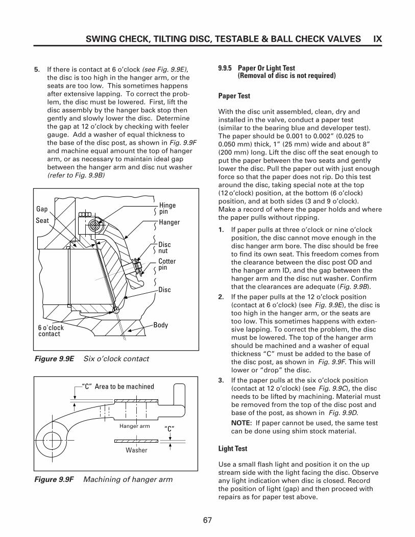
67
SWING CHECK, TILTING DISC, TESTABLE & BALL CHECK VALVES IX
HingepinHanger
Disc nutCotterpin
Disc
Body
Gap
Seat
6 o'clockcontact
Figure 9.9E Six o’clock contact
“C” Area to be machined
“C”
Figure 9.9F Machining of hanger arm
Washer
Hanger arm
5. If there is contact at 6 o’clock (see Fig. 9.9E),the disc is too high in the hanger arm, or theseats are too low. This sometimes happensafter extensive lapping. To correct the prob-lem, the disc must be lowered. First, lift thedisc assembly by the hanger back stop thengently and slowly lower the disc. Determinethe gap at 12 o’clock by checking with feelergauge. Add a washer of equal thickness to the base of the disc post, as shown in Fig. 9.9Fand machine equal amount the top of hangerarm, or as necessary to maintain ideal gapbetween the hanger arm and disc nut washer(refer to Fig. 9.9B)
9.9.5 Paper Or Light Test(Removal of disc is not required)
Paper Test
With the disc unit assembled, clean, dry andinstalled in the valve, conduct a paper test(similar to the bearing blue and developer test).The paper should be 0.001 to 0.002” (0.025 to0.050 mm) thick, 1” (25 mm) wide and about 8”(200 mm) long. Lift the disc off the seat enough toput the paper between the two seats and gentlylower the disc. Pull the paper out with just enoughforce so that the paper does not rip. Do this testaround the disc, taking special note at the top(12o’clock) position, at the bottom (6 o’clock) position, and at both sides (3 and 9 o’clock). Make a record of where the paper holds and wherethe paper pulls without ripping.
1. If paper pulls at three o’clock or nine o’clockposition, the disc cannot move enough in thedisc hanger arm bore. The disc should be freeto find its own seat. This freedom comes fromthe clearance between the disc post OD andthe hanger arm ID, and the gap between thehanger arm and the disc nut washer. Confirmthat the clearances are adequate (Fig. 9.9B).
2. If the paper pulls at the 12 o’clock position(contact at 6 o’clock) (see Fig. 9.9E), the disc istoo high in the hanger arm, or the seats aretoo low. This sometimes happens with exten-sive lapping. To correct the problem, the discmust be lowered. The top of the hanger armshould be machined and a washer of equalthickness “C” must be added to the base ofthe disc post, as shown in Fig. 9.9F. This willlower or “drop” the disc.
3. If the paper pulls at the six o’clock position(contact at 12 o’clock) (see Fig. 9.9C), the discneeds to be lifted by machining. Material mustbe removed from the top of the disc post andbase of the post, as shown in Fig. 9.9D.
NOTE: If paper cannot be used, the same testcan be done using shim stock material.
Light Test
Use a small flash light and position it on the upstream side with the light facing the disc. Observeany light indication when disc is closed. Recordthe position of light (gap) and then proceed withrepairs as for paper test above.
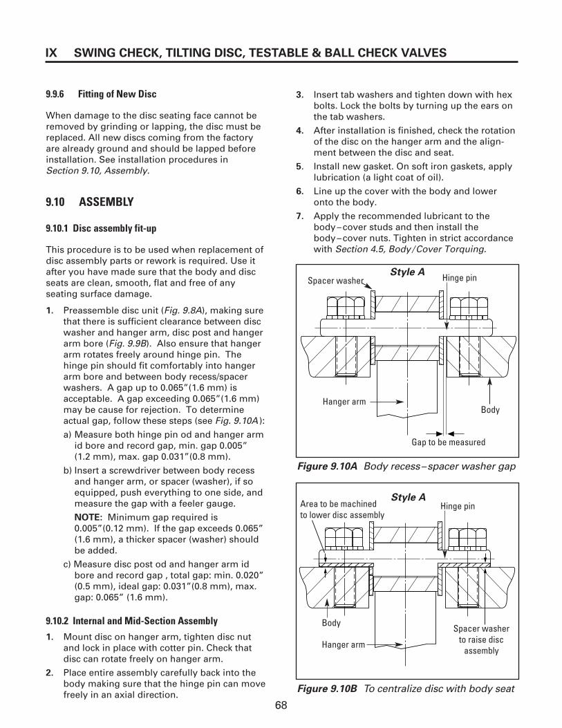
68
IX SWING CHECK, TILTING DISC, TESTABLE & BALL CHECK VALVES
9.9.6 Fitting of New Disc
When damage to the disc seating face cannot beremoved by grinding or lapping, the disc must bereplaced. All new discs coming from the factoryare already ground and should be lapped beforeinstallation. See installation procedures inSection 9.10, Assembly.
9.10 ASSEMBLY
9.10.1 Disc assembly fit-up
This procedure is to be used when replacement ofdisc assembly parts or rework is required. Use itafter you have made sure that the body and discseats are clean, smooth, flat and free of anyseating surface damage.
1. Preassemble disc unit (Fig. 9.8A), making surethat there is sufficient clearance between discwasher and hanger arm, disc post and hangerarm bore (Fig. 9.9B). Also ensure that hangerarm rotates freely around hinge pin. Thehinge pin should fit comfortably into hangerarm bore and between body recess/spacerwashers. A gap up to 0.065”(1.6 mm) is acceptable. A gap exceeding 0.065”(1.6 mm)may be cause for rejection. To determineactual gap, follow these steps (see Fig. 9.10A ):
a) Measure both hinge pin od and hanger armid bore and record gap, min. gap 0.005”(1.2 mm), max. gap 0.031”(0.8 mm).
b) Insert a screwdriver between body recessand hanger arm, or spacer (washer), if soequipped, push everything to one side, andmeasure the gap with a feeler gauge.
NOTE: Minimum gap required is 0.005”(0.12 mm). If the gap exceeds 0.065”(1.6 mm), a thicker spacer (washer) shouldbe added.
c) Measure disc post od and hanger arm idbore and record gap , total gap: min. 0.020”(0.5 mm), ideal gap: 0.031”(0.8 mm), max.gap: 0.065” (1.6 mm).
9.10.2 Internal and Mid-Section Assembly
1. Mount disc on hanger arm, tighten disc nutand lock in place with cotter pin. Check thatdisc can rotate freely on hanger arm.
2. Place entire assembly carefully back into thebody making sure that the hinge pin can movefreely in an axial direction.
3. Insert tab washers and tighten down with hexbolts. Lock the bolts by turning up the ears onthe tab washers.
4. After installation is finished, check the rotationof the disc on the hanger arm and the align-ment between the disc and seat.
5. Install new gasket. On soft iron gaskets, applylubrication (a light coat of oil).
6. Line up the cover with the body and loweronto the body.
7. Apply the recommended lubricant to thebody–cover studs and then install thebody–cover nuts. Tighten in strict accordancewith Section 4.5, Body /Cover Torquing.
Style A
Gap to be measured
Hanger arm
Hinge pin
Figure 9.10A Body recess–spacer washer gap
Figure 9.10B To centralize disc with body seat
Style A
Hanger arm
Body
Hinge pin
Body
Spacer washer
Spacer washerto raise disc
assembly
Area to be machinedto lower disc assembly
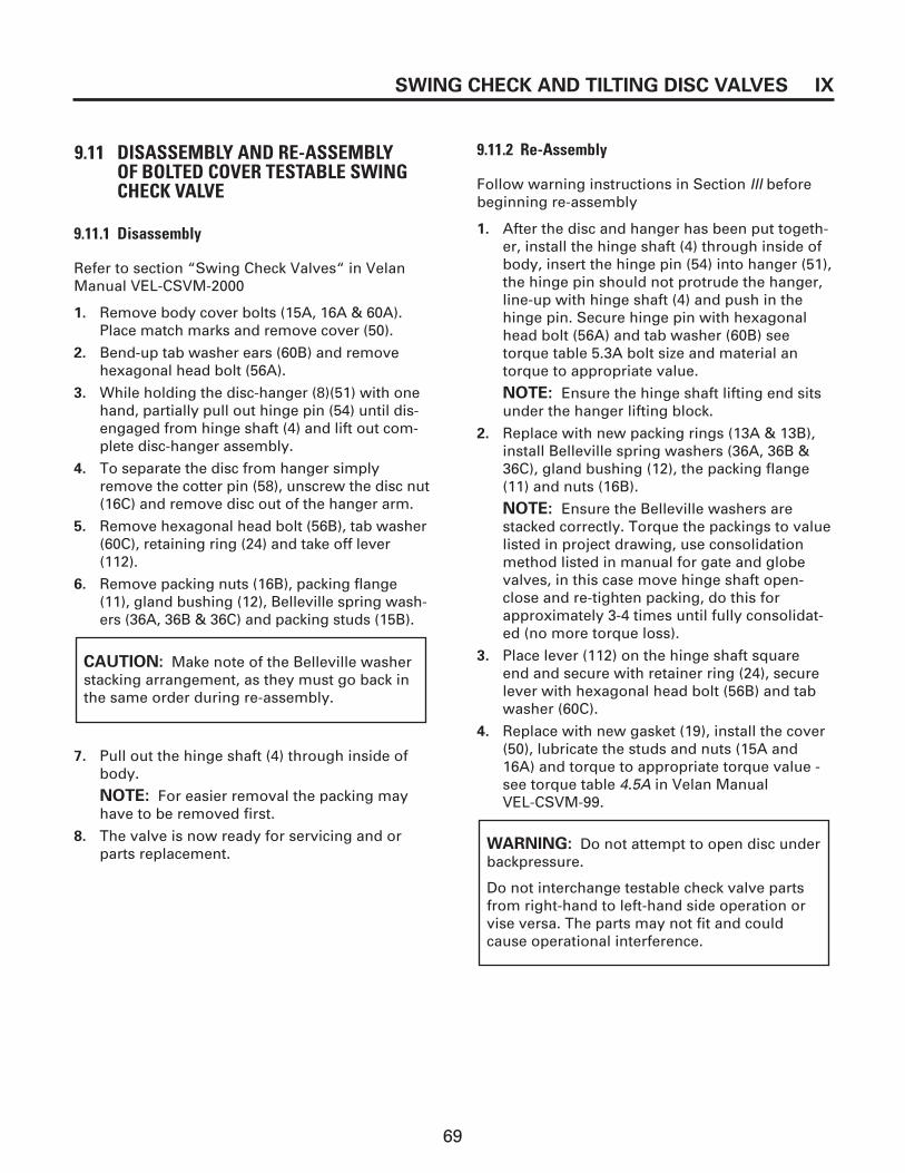
69
SWING CHECK AND TILTING DISC VALVES IX
9.11 DISASSEMBLY AND RE-ASSEMBLY OF BOLTED COVER TESTABLE SWINGCHECK VALVE
9.11.1 Disassembly
Refer to section “Swing Check Valves“ in VelanManual VEL-CSVM-2000
1. Remove body cover bolts (15A, 16A & 60A).Place match marks and remove cover (50).
2. Bend-up tab washer ears (60B) and removehexagonal head bolt (56A).
3. While holding the disc-hanger (8)(51) with onehand, partially pull out hinge pin (54) until dis-engaged from hinge shaft (4) and lift out com-plete disc-hanger assembly.
4. To separate the disc from hanger simplyremove the cotter pin (58), unscrew the disc nut(16C) and remove disc out of the hanger arm.
5. Remove hexagonal head bolt (56B), tab washer(60C), retaining ring (24) and take off lever(112).
6. Remove packing nuts (16B), packing flange(11), gland bushing (12), Belleville spring wash-ers (36A, 36B & 36C) and packing studs (15B).
7. Pull out the hinge shaft (4) through inside ofbody.
NOTE: For easier removal the packing mayhave to be removed first.
8. The valve is now ready for servicing and orparts replacement.
CAUTION: Make note of the Belleville washerstacking arrangement, as they must go back inthe same order during re-assembly.
9.11.2 Re-Assembly
Follow warning instructions in Section III beforebeginning re-assembly
1. After the disc and hanger has been put togeth-er, install the hinge shaft (4) through inside ofbody, insert the hinge pin (54) into hanger (51),the hinge pin should not protrude the hanger,line-up with hinge shaft (4) and push in thehinge pin. Secure hinge pin with hexagonalhead bolt (56A) and tab washer (60B) seetorque table 5.3A bolt size and material antorque to appropriate value.
NOTE: Ensure the hinge shaft lifting end sitsunder the hanger lifting block.
2. Replace with new packing rings (13A & 13B),install Belleville spring washers (36A, 36B &36C), gland bushing (12), the packing flange(11) and nuts (16B).
NOTE: Ensure the Belleville washers arestacked correctly. Torque the packings to valuelisted in project drawing, use consolidationmethod listed in manual for gate and globevalves, in this case move hinge shaft open-close and re-tighten packing, do this forapproximately 3-4 times until fully consolidat-ed (no more torque loss).
3. Place lever (112) on the hinge shaft square end and secure with retainer ring (24), securelever with hexagonal head bolt (56B) and tabwasher (60C).
4. Replace with new gasket (19), install the cover(50), lubricate the studs and nuts (15A and16A) and torque to appropriate torque value -see torque table 4.5A in Velan Manual VEL-CSVM-99.
WARNING: Do not attempt to open disc underbackpressure.
Do not interchange testable check valve partsfrom right-hand to left-hand side operation orvise versa. The parts may not fit and couldcause operational interference.
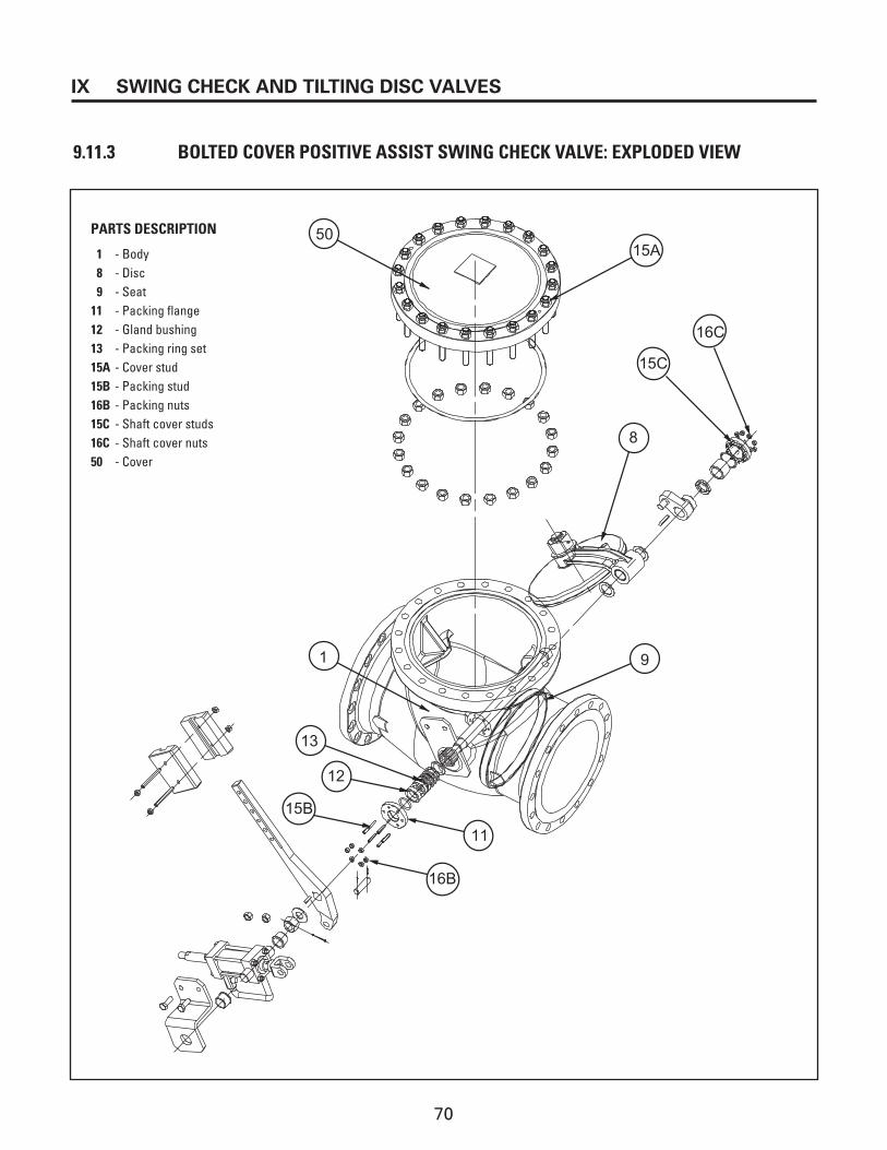
70
IX SWING CHECK AND TILTING DISC VALVES
9.11.3 BOLTED COVER POSITIVE ASSIST SWING CHECK VALVE: EXPLODED VIEW
50
1
13
12
15B
16B
11
9
8
15A
16C
15C
PARTS DESCRIPTION
1 - Body8 - Disc9 - Seat
11 - Packing flange12 - Gland bushing13 - Packing ring set15A - Cover stud15B - Packing stud16B - Packing nuts15C - Shaft cover studs16C - Shaft cover nuts50 - Cover

71
SWING CHECK AND TILTING DISC VALVES IX
9.12 DISASSEMBLY AND RE-ASSEMBLY OFBOLTED COVER BALL CHECK VALVE
9.12.1 Disassembly
Refer to section “Swing Check Valves“ in VelanManual VEL-CSVM-2001.
1. Remove body cover bolts (15, 16 & 60). Placematch marks and remove cover (50).
2. Match mark Ball cage unit (47) with body (1)using the cage unit pull up holes, screw in twoeyebolts and lift out complete cage unit.
NOTE: It may be necessary to use a hoist orcome along to lift out the cage unit. Careshould be taken while lifting to ensure the cageunit does not become cocked.
3. With the cage unit out of the valve body,remove ball (6), set screw (35) and the seat (9).
NOTE: The seat is screwed in type, to remove,unscrew counter clockwise.
4. Once the seat has been taken out of the cageunit, remove seat insert (72), and if necessary“O“ ring (74).
NOTE: Ball stopper (49) is welded to cover, toremove the stopper grind off the welds flushwith cover and stopper.
5. Seat insert (72) seating angle is 25° (degrees),in case of damage it must be replaced.
6. The seat (9) stellited surface angle is 30°(degrees). In case of soft seat failure this actsas a secondary seal. Under normal conditionswhen the ball makes contact with soft seat(seat insert) the secondary stellite seating sur-face should have a gap of approximately0.014“ (0.35 mm). In case of damage to thissurface a maximum of 0.010“ (0.25 mm) canbe removed by lapping. If damage is in excessof 0.010“ (0.25 mm) the seat must be replaces.
9.12.2 Re-Assembly
Follow warning instructions in Section III beforebeginning re-assembly
1. Slide in seat insert (72) into cage unit (47),screw in clockwise the seat (9) until metal tometal with bottom of cage unit. Secure seatwith set screw (35).
2. Place the ball (6) into cage unit and install O-ring (74).
3. Carefully lower the entire unit into the valvebody. Follow match marks and ensure it hasengaged with centering pin (61).
4. Replace with new gasket (19). Lubricate withanti-seize compound and install studs (15),install cover (50), place tab washers (60), lubri-cate stud / nut threads and nut flats and torquein accordance with Velan torquing procedureand torque table 4.5A in Velan Manual VEL-CSVM-2001.
5. Secure nut with tab washer (60) by bendingtab ears against the nut flat and cover.

72
IX SWING CHECK AND TILTING DISC VALVES
9.12.3 BALL CHECK CAGE UNIT: EXPLODED VIEW
1
8
15
16
60
19
35
50
61
7273A
74
73B
PARTS DESCRIPTION
1 - Body8 - Ball
15 - Stud16 - Nuts19 - Gasket35 - Set screws50 - Cover60 - Tab lock washers61 - Dowel pin72 - Soft seat73A - Soft seat retainer73B - Check ball cage74 - O-ring

73
APPENDIX X
Figure 10.1A Manual gear actuator—Style 1
10.1 PROCEDURE FOR REMOVING MANUALGEAR ACTUATOR
Velan valves can be equipped with a variety ofmanual gear actuators. Actuators of this typecome in two main styles: one for applicationswhere only rotary torque is required, and onefor applications requiring both rotary torque andlinear thrust.
Generally, all pressure must be relieved from bothsides of the valve before removal of the manualgear actuator. Exceptions to this rule includevalves which have a self-contained unit.
IMPORTANT: Determine the actuator stylethat is mounted on the valve you are servic-ing. If it is not possible to determine the styleof actuator, refer to the actuator manufactur-er's maintenance and instruction manual orcontact your local Velan representative formore technical assistance.
10.1.1 Style I (Fig.10.1A)
1. Valves with Style 1 manual gear actuators areequipped with a self-contained thrust unit. Thisactuator can be removed under line pressure.
2. Remove housing actuator bolting (17B).
3. Using a hoist, raise the actuator (32) above thestem (4) and stem nut (88).
4. To repair the actuator, refer to the manufacturer'sinstruction manual. If there is further work to doon this valve, refer to the appropriate sectionof this manual.
5. The disassembly of the self-contained thrustunit follows the same procedure as describedin Disassembly Valve Top Works.
PARTS DESCRIPTION3 - Yoke4 - Stem
17A - Yoke/housing cap screw28 - Yoke/housing cover
29A - Bearing32 - Gear actuator34 - Grease fitting88 - Stem nut
113 - Stem nut gear driver178 - Housing/actuator
cap screw

74
X APPENDIX
10.1.2 Style 2 (Fig.10.1B)
1. Valves with a Style 2 manual gear actuator are equipped with a self-contained thrust unitwhich will be removed with the actuator.Therefore the actuator cannot be removedunder line pressure. The pressure must berelieved.
NOTE: In case the valve can be fully opened,then the actuator can be removed under linepressure. Follow steps 3, 4, 5 and 6.
2. The valve should be in a partially open position.
3. Make sure that the packing flange nuts are tight.
4. Remove the yoke-actuator bolting (17B).
5. Turn the actuator handwheel clockwise. Thiswill cause the actuator (32) to rise and unthreadfrom the valve stem. As this takes place, theweight of the actuator should be supported by ahoist to prevent damage to the stem thread orany internal part of the valve.
NOTE: Applications where both rotary torque and linear thrust are required.
Figure 10.1B Manual gear actuator—Style 2
PARTS DESCRIPTION03 - Yoke04 - Stem17B - Yoke/actuator cap screw32 - Gear actuator
ASSEMBLY EXPLODED VIEW
6. To repair the actuator, refer to the manufacturer's instruction manual. If there isfurther work to be done on the valve, refer tothe appropriate section of this manual.
IMPORTANT: Velan does not recommend interchanging of actuator parts as this maycause parts to be misfitted that could result inactuator damage making the valve inoperable. If parts must be interchanged contact VelanCustomer Service Department for instruction.
CAUTION: When reinstalling actuator, the valve should be in a slightly off-seated position (main seat or backseat) for centering purposes.

75
APPENDIX X
IMPORTANT: For torque seated valves, thetorque switch of the motor-actuated valve isset during factory assembly to close the valveagainst the specified differential pressure andrequires the same special attention for resetting.
WARNING: Should it become necessary tochange the torque switch setting for any reason, contact your Velan Customer ServiceManager to obtain a correct new setting fromthe factory.
10.2 PROCEDURE FOR REMOVINGMOTOR ACTUATOR
Velan valves can be equipped with a variety ofelectrical motor actuators. Motor actuators aremounted through two different methods. Someunits are attached directly to the yoke (Fig. 10.2A),and some are attached to an adapter plate andthen to the valve yoke (Fig. 10.2B). Both methodshave the same removal procedure.
Figure10.2A Motor actuator- direct attachment
Figure 10.2B Motor actuator - adapter plate attachment (assembly)
Refer to Fig. 10.2C and Fig. 10.2D
NOTE: If the valve is in full open position, themotor actuator and bevelgear can be removedunder line pressure, otherwise.
CAUTION:
1. If the valve packing material is changedfor any reason, the torque switch settingmay have to be changed in this casecontact Velan customer serviceDepartment.
2. Upon reassembly of a valve equippedwith an electro-mechanical actuator, theopen and close limit switches must bereset. Please refer to the maintenanceand instruction manual provided by theactuator manufacturer for appropriateinstructions.IMPORTANT: Velan recommends toreset open limit switch as a rule ofthumb 1/4” (6 mm) off back seated position. For torque seated valves onlythe close limit switch should be adjustedat approximately 95% of closed valvetravel, this is to allow sufficient torqueswitch by-pass during unseating.
3. When checking for proper rotation ofthe electrical actuator, make sure thatthe valve is in mid-stroke position. If the three-phase wiring connection isincorrect, the valve will close when theopen button is pressed and the closetorque switch will not function, whichcould damage the valve. If the valvedoes not travel in the correct direction,then simply interchange any two of thethree power connections.
4. When checking for full stroke of thevalve without pressure in the line, theclosing torque switch should be set toits minimum value which will close thevalve until all testing is finished. Thetorque switch should then be reset to its recommended value.

76
X APPENDIX
1. All pressure must be relieved from both sidesof the valve before removing the motor actuator and bevelgear.
2. The valve should be in a partially open position.
3. Disconnect the electrical wiring from theactuator.
4. Tighten the packing flange nuts.
5. Remove all actuator bolting (17C) from theunderside of the yoke flange.
NOTE: If removing the motor actuator withbevelgear Fig. 10.2D, remove hex bolts (17)push out the motor actuator (32) frombevelgear keyed stem (33). If removing bevelgear, remove cap screws (17C), rotatebevelgear clockwise this will cause the bevelgear to unthread from the stem.
6. All electrical actuators have an automatichand-wheel declutching arrangement. Inmost cases, move the lever from the motor operation position to the hand operation position (manual mode).
NOTE: Do not try to force declutch lever intoan operation position.
Figure 10.2C Motor actuator - Adapter plateattachment (Exploded view)
PARTS DESCRIPTION03 - Yoke04 - Stem15 - Adapter/actuator
stud16 - Adapter/actuator
nut17C - Yoke/adapter
cap screw32 - Motor actuator37 - Adapter plate
3433
17
32
17C
50
04
03
Figure 10.2D Bevelgear actuator(Exploded view)
7. Turn the actuator handwheel clockwise toclose the valve. This will cause the actuator torise and unthread itself from the valve stem.As this takes place, the weight of the actuatorshould be supported by a hoist to preventdamage to the stem or to the internal parts ofthe valve.
8. If further disassembly of the actuator isrequired, refer to the maintenance manualprovided by the actuator manufacturer.
9. If there is further work to be performed on thevalve, refer to the proper valve disassemblyand maintenance section in this manual.
CAUTION: When reinstalling actuator, thevalve should be in the slightly off-seatedposition (main seat or backseat) forcentering purposes.
PARTS DESCRIPTION03 - Yoke 32 - Motor actuator04 - Stem 33 - Bevelgear actuator17 - Bevelgear/actuator hexbolt 50 - Stem protector17C -Yoke/bevelgear cap screw

77
APPENDIX X
Figure 10.3A Examples of coupling
Figure 10.3B Removal of actuators
PARTS DESCRIPTION3 - Yoke4 - Stem
17B - Yoke/actuator cap screw
32 - Actuator35 - Coupling
set screw97 - Coupling
PARTS DESCRIPTION4 - Stem
4B - Actuator stem16 - Jam nut97 - Coupling
10.3 PROCEDURE FOR MOTOR HYDRAULIC OR PNEUMATIC ACTUATORS (Fig. 10.3A)
The following instructions will give you a generalguide for removal and reinstallation of a hydraulicor pneumatic actuator. All hydraulic or pneumaticactuators have a connection between the valvestem and the stem of the actuator. All these connections are formed by some type of coupling.Fig. 10.3A illustrates some examples of couplingused on Velan valves. As a rule, examine this connection first to understand how the couplingworks.
Removal of Actuators (Fig. 10.3B )
1. All pressure must be relieved from both sidesof the valve before removal of actuator.
2. All air pressure must be relieved from actuatorbefore disassembly.
3. Remove yoke-actuator bolting (17B).NOTE: In case of fail close actuator type (airfail spring to close). Before air is relievedreplace two capscrews (17B) one opposite theother with longer (twice the length) studs orthreaded rod, relieve air and gradually releasespring tension by backing off stud nuts.
4. Loosen coupling (97).
NOTE: On some actuators, it is necessary torotate the actuator stem to remove thisconnection.
5. When the stem threads are disengaged, liftthe actuator (32) clear of the yoke and place itdown on a clean area. If further disassembly on the actuator is required, refer to the manufacturer's maintenance and instructionmanual.
PRECAUTION: Examine coupling (97)for set screw (35) or any locking devicebefore loosening it.
6. If there is further work to be performed on thevalve, refer to the proper valve disassemblysection in this manual.
CAUTION: When reinstalling actuator,the valve should be slightly off seatedposition (main seat or backseat) for centering purposes.
10.4 SPARE PARTSAll parts on any valve can be ordered, but Velandoes not recommend changing all parts in the field(e.g. integral seat, integral backseat, wedge guides,etc.).
Changing these parts may require special fitting. Inthese cases, it is best to get in touch with your localVelan representative who will help you determinethe way to restore your valve with a minimum oftime and expense.
When ordering spare parts, correctly determinewhich parts are required. After this is done, presentVelan with the following information, preferably:
1. Velan order number2. Velan item number (if more than one item)3. Velan figure number and drawing number
(usually found on the valve name plate)
OR (in absence of the above)
1. Customer order number2. Customer item number3. Valve size, type, pressure class and drawing no.

TERMS AND CONDITIONS OF SALE
CONTRACT: Orders are subject to acceptance bythe Velan Companies hereinafter referred to as theseller. No terms or conditions of Purchaser's ordercontrary to the Seller's terms and condition shallbe binding upon the Seller unless specificallyagreed to by the Seller in writing.
MINIMUM ORDER CHARGE: $500.00 net.PRICES: All quoted prices are subject to change bythe seller without prior notice and, unless other-wise stipulated by Seller, are understood to beF.O.B. Seller's plant, with delivery to carrier consti-tuting delivery to purchaser. Right to possession ofthe material to secure the payment of the purchaseprice shall remain in Seller until all paymentstherefore shall have been fully made. For the pro-tection of the Purchaser and the Seller, verbal cus-tomer orders must be confirmed by a formal writ-ten purchase order. If a written purchase order isnot received within ten days or a verbal order,product descriptions, quantities, specifications,etc., as set forth in Seller's acknowledgement andinvoice shall be conclusive and binding on bothparties. Any order that is shipped before receipt ofconfirmation which might have been entered incor-rectly and would require remedial action would befor the Purchaser's account.
TAXES: All prices are exclusive of taxes. Sales,use and other taxes, by whomsoever levied, are tobe paid by the Purchaser, and unless invoiced, areto be paid by the Purchaser directly to the appro-priate governmental agency.
DELIVERY: Delivery or shipment specified isSeller's best estimate and Seller shall not be liablefor delay in deliveries resulting from any causewhatsoever. Failure to ship on or near the estimat-ed date shall not entitle Purchaser to cancel hisorder without charge.
RETURN OF MATERIALS: Materials may bereturned only with prior written agreement ofSeller.
CANCELLATION: Cancellation of orders may bemade only with the Seller's written consent andPurchaser shall be subject to cancellation charges.PRODUCT WARRANTY: Seller warrants the equip-ment of its own manufacture to be free of defectsin material and workmanship, under normal useand proper operation for a period of one year fromthe date of shipment from Seller's plant. Seller'sobligation under warranty shall be strictly limited,at Seller's option, to: (i) furnishing replacementparts for or repairing without charge to Purchaser,F.O.B. Seller's plant or (ii) issuing written autho-rization for Purchaser or others to replace or repairwithout charge to Purchaser, at costs comparableto Seller's normal manufacturing costs those parts
proven defective, or (iii) in discharge of Seller'smaximum liability herewith, refunding all moniespaid by Purchaser to Seller for the Product and, atdiscretion of Seller, having the product removedand returned to Seller at Purchaser's expense. Alltransportation charges relative to corrective work,defective parts or replacement parts shall be borneby Purchaser. Purchaser shall give Seller immedi-ate notice upon discovery of any defect. Theundertaking of repairs or replacements byPurchaser or its agents without Seller's writtenconsent shall relieve seller of all responsibilityherewith.
Finished materials and accessories purchasedfrom other manufacturers are warranted only tothe extent of the manufacturer's warranty toSeller.
Any alteration in material or design of Seller's prod-uct or component parts thereof by Purchaser or oth-ers without written authorization by Seller voids allobligations of Seller regarding the product and anyassociated warranty herein stated or implied.
Seller's sole liability shall be exclusively as setforth herein, and Seller shall not be liable for anyincidental or consequential damages due to itsbreach of any warranty herein contained, or other-wise. Without limitation to the foregoing, in noevent shall Seller be liable for the loss of use ofthe product or of any other product, process,plant, equipment, or facilities of the Purchaser orend-user whether partially or wholly due todefects in material and /or workmanship and /ordesign of Seller's product, and in no event shallSeller be liable for removal of appurtenances orincidentals such as connections, pipe work andsimilar items of obstruction or for any costbrought about by the necessity of removing theproduct from its point of installation.
Seller makes no warranty of any kind whatsoever,expressed or implied, other then is specifically stat-ed herein; and there are no warranties of mer-chantability and/or fitness for a particular purposewhich exceed the obligations and warranties specifi-cally stated herein.
Parts furnished without charge as replacementsfor original parts under warranty are warranted forthat period of time during which the original partswarranty is effective.
ALL SHIPMENTS WILL BE F.O.B. PLANT LOCATION.SHIPMENTS WILL BE MADE VIA MOST ECONOMI-CAL CARRIERS UNLESS OTHERWISE REQUEST-ED.TERMS: NET 30 DAYS FROM DATE OF INVOICE:11⁄2% PER MONTH OF ALL OVERDUE ACCOUNTS,ALL TAXES EXTRA. PRICES SUBJECT TO CHANGEWITHOUT NOTICE.
78