casting lithium targets for use in photonuclear physics
TRANSCRIPT

University of SaskatchewanSubatomic Physics Internal Report
SPIR 138
Casting lithium targets for use in photonuclear physics
Ward Andrew Wurtz
4th January 2007
Contents
1 Introduction 1
2 Handling Li 1
3 Target design 1
4 Description of the apparatus 2
5 Procedure for casting the targets 45.1 Using the glove box . . . . . . . . . . . . . . . . . . . . . . . . . . . . . . . . . . . . 45.2 Casting the natural Li target . . . . . . . . . . . . . . . . . . . . . . . . . . . . . . . 55.3 Casting the 6Li target . . . . . . . . . . . . . . . . . . . . . . . . . . . . . . . . . . . 8
6 Conclusion 9
References 9
A Appendix: Apparatus drawings 9
3 TARGET DESIGN
1 Introduction
The experimental nuclear physics group at the University of Saskatchewan desires to study the photo-disintegration of Li isotopes. As there are two isotopes of Li, 6Li and 7Li, we must build two targets.The first target is made from isotopically enriched 6Li. The second target is made from natural Li,which is 92.4% 7Li. The impurity in the natural Li target can be corrected by using the results of the6Li experiment.
We had in our possession a 6Li target used in an experiment [1] at the Saskatchewan AcceleratorLaboratory (SAL). This target has a volume of 201 cm3 and the centre cylinder has been redrawn inappendix A. Also, we purchased 100 g (187 cm3) of natural Li.
2 Handling Li
Being a group I element, Li is a metal and is highly reactive. It will react with the atmosphere, waterand many other metals. Li must be handled in an inert atmosphere, such as argon. It should never comeinto contact with moisture and should be kept away from other other metals. Therefore, only plasticscame into contact with the Li during the casting of our targets.
A further complication occurs in that the Li will be molten for some time. Molten Li reacts muchmore readily than solid Li so extra care will need to be taken.
Before handling Li, consult a Material Safety Data Sheet (MSDS).
3 Target design
Both the 6Li and 7Li targets were desired to have the same geometry. A third, empty target was built inorder to do background measurements. The three targets were made from Teflon tubes as Teflon has ahigh melting point and does not react with Li.
The diameters of the targets were chosen to accommodate the beam size at the High IntensityGamma Source at Duke University, Durham, NC, USA. The diameter was chosen to be 4.1 cm basedon previous deuterium targets [2]. The length of the targets was chosen based on the quantity of Liavailable. A length of 12.7 cm was chosen giving a volume of 167 cm3. This conservative lengthensured that we would have enough 6Li even if air had leaked into the old target causing much of it toform LiHO.
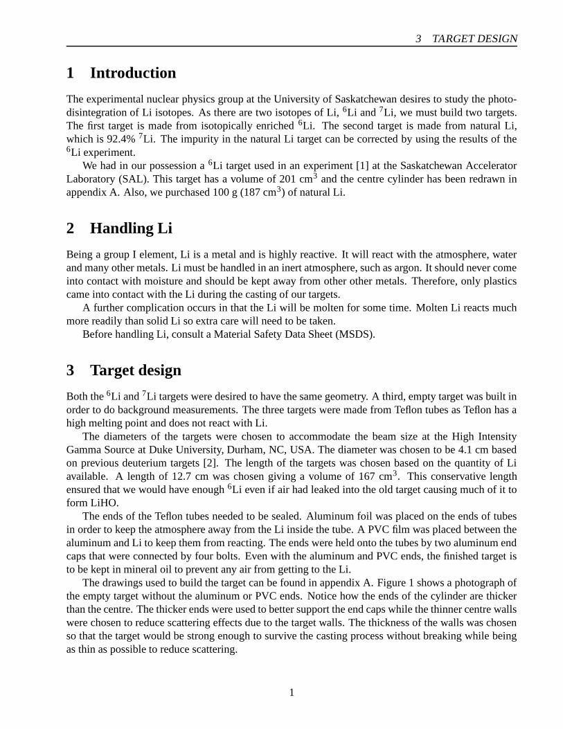
The ends of the Teflon tubes needed to be sealed. Aluminum foil was placed on the ends of tubesin order to keep the atmosphere away from the Li inside the tube. A PVC film was placed between thealuminum and Li to keep them from reacting. The ends were held onto the tubes by two aluminum endcaps that were connected by four bolts. Even with the aluminum and PVC ends, the finished target isto be kept in mineral oil to prevent any air from getting to the Li.
The drawings used to build the target can be found in appendix A. Figure 1 shows a photograph ofthe empty target without the aluminum or PVC ends. Notice how the ends of the cylinder are thickerthan the centre. The thicker ends were used to better support the end caps while the thinner centre wallswere chosen to reduce scattering effects due to the target walls. The thickness of the walls was chosenso that the target would be strong enough to survive the casting process without breaking while beingas thin as possible to reduce scattering.
1

4 DESCRIPTION OF THE APPARATUS
Figure 1: Empty target tube, end caps and bolts without aluminum foil or PVC ends
4 Description of the apparatus
Because the SAL 6Li had a radically different geometry than desired, the target needed to be recast.Also, the natural Li came in the form of a wire with a 3.2 mm diameter meaning that it had to be meltedand cast into the correct geometry. Thus, in both cases, we needed to melt and cast Li.
The casting of Li must be done in an inert atmosphere, such as argon. In order to handle the Li in anargon atmosphere a Labconco 50601-00 glove box [3] was used at the Canadian Light Source (CLS) atthe University of Saskatchewan. This glove box was placed in the experimental hall of the CLS and ispictured in figure 2. The glove box was connected to the argon gas by the CLS staff. The pressure wasregulated by a bubbler and the argon was vented into the experimental hall. The argon could be ventedinto the experimental hall without danger as it is a large room.
An apparatus for melting and casting the Li was built and placed in the glove box. The drawingsused to build the apparatus can be found in appendix A. The apparatus in its configuration for castingthe natural Li target can be found in figure 3 and figure 4 shows the apparatus in its configuration forcasting the 6Li target. Notice that the natural Li configuration is a subset of the 6Li configuration.
Central to the natural Li configuration is the target cylinder described in section 3 and pictured infigure 1. The end caps were removed from the target and it was placed on a thin Kapton layer on analuminum plate. The aluminum plate has a special hole for the thermometer probe and sits upon ahot-plate style heater. The Kapton ensures that the Li does not bond to the aluminum but allows heatto be transfered from the aluminum plate to the Li inside the target. The target cylinder is capped onthe top by a Teflon end cap. This end cap has a hole so that Li may be placed inside the target cylinder.The apparatus is held together by four bolts running from the aluminum plate through the Teflon endcap. These bolts are spring loaded at the top to accommodate for thermal expansion while heating thetarget. In order to prevent Li from touching the steel bolts, Kapton pieces were placed over the endsof the bolts. These Kapton pieces were only used with the natural Li configuration. The rest of theapparatus was similarly setup for the 6Li configuration.
2

4 DESCRIPTION OF THE APPARATUS
Figure 2: Glove box used to control the atmosphere during the casting of the Li targets
Figure 3: The apparatus in its configuration for casting the natural Li target
3

5 PROCEDURE FOR CASTING THE TARGETS
Figure 4: The apparatus in its configuration for casting the 6Li target
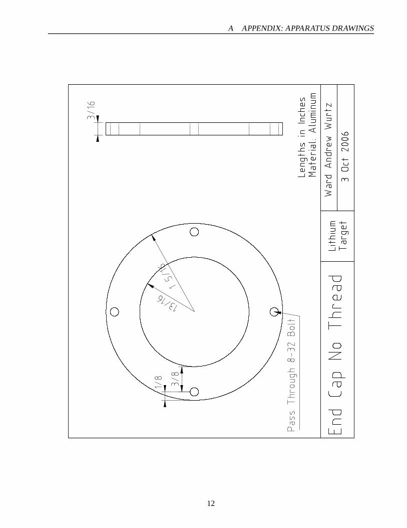
Since the casting of the 6Li target involves pouring molten 6Li, the 6Li apparatus configuration ismore complex. A Teflon funnel is mounted on top of the apparatus and can be viewed in figure 4 restingon the aluminum plate. Since the funnel is relatively heavy it raises the centre-of-mass of the castingapparatus. Therefore, three legs were added to three corners of the apparatus and the heater was movedto support the fourth corner. This ensured that the apparatus would not tip over during the pouringof the 6Li. Also sitting on the aluminum plate in figure 4 is the old 6Li target placed inside a specialapparatus for melting it. The centre cylinder is that which the target was originally cast into. Below thecentre cylinder is a Kapton layer sitting on an aluminum plate. Above the centre cylinder is a Tefloncap with holes specially made for pouring the molten 6Li. The melting apparatus is held together byseven spring-loaded bolts and is placed directly on the aluminum plate. Both the funnel and the meltingapparatus have aluminum tabs so that they may be lifted with pliers when hot.
Beyond the above mentioned apparatus there were many smaller parts including tools, paper towel,sealing containers and a large Kapton sheet that covered the bottom of the glove box. This apparatusallowed us to safely cast the two Li targets.
5 Procedure for casting the targets
5.1 Using the glove box
The CLS glove box was connected to an argon gas cylinder as shown in figure 5. The first step inpreparing the atmosphere was to purge the glove box. An inflatable bag was placed inside the glovebox and filled with argon. This caused the pressure inside the glove box to increase and the air passedout through the bubbler. After the bag had been inflated to its maximum size, it was disconnected fromthe argon line and the external valve was opened. The ‘Gas In’ valve was opened and the glove box wasfilled with argon, forcing the argon in the bag out of the glove box and into the CLS experimental hall.Repeating this procedure two times was found to give a good atmosphere and three times an excellent
4

5.2 Casting the natural Li target 5 PROCEDURE FOR CASTING THE TARGETS
Gas
Cyl
inde
rRegulator
Transfer Chamber
Glove Box
Inflatable Bag
Gas
In
Gas
In
Bag
Fill
Bub
bler
Vacuum
Figure 5: Diagram of the argon gas system used to control the atmosphere inside the glove box
atmosphere for the purposes of casting Li.Once the glove box had been purged of air, the bag was deflated and we used the bubbler to maintain
a steady flow of argon through the glove box. We kept the glove box at positive pressure to prevent airfrom entering through the seals that were good but imperfect.
The transfer chamber could be used in order to get equipment in and out of the glove box withouthaving to purge the atmosphere each time. To move an object into the glove box it was first placedin the transfer chamber from the outside while the inside door of the chamber remained sealed. Theoutside door was then sealed and a vacuum was used to pump the air out of the chamber. The chambercould then be filled with argon from the cylinder. Performing this process twice was found to maintaina good atmosphere when inserting equipment into the glove box.
To remove a piece of equipment from the glove box the transfer chamber would first be sealed andpurged of air. The inside door could then be safely opened and the object placed inside the transferchamber. Once the inside door was closed, the outside door could be opened and the object removed.
The steps outlined in this section made melting and casting the Li safe. A quick quality check couldbe done on the atmosphere by striking a piece of Li with a blunt object. If red sparks could be seen,then the atmosphere was insufficiently pure. However, performing this test after the above steps weretaken always demonstrated that the atmosphere was sufficiently pure.
5.2 Casting the natural Li target
The casting of the natural Li target was performed before the 6Li target because the procedure is moresimple as we did not need to pour molten Li. The natural Li was purchased from Sigma Aldrich. Wechose to use natural Li due to the high cost of enriched 7Li.
The Li arrived in a special shipping container. It was shipped inside a large box filled with packingfoam. Inside the box there was a sealed aluminum container with a removable lid. This inside containerwas not opened until moments before the natural Li was placed inside the transfer chamber. Thealuminum container was filled with sand and there was a small glass jar containing 3.2 mm Li wire
5

5.2 Casting the natural Li target 5 PROCEDURE FOR CASTING THE TARGETS
and a quantity of mineral oil pictured in figure 6. It was deemed that the glass jar needed to be opened
Figure 6: The natural Li wire
before it was placed inside the transfer chamber or it could break when the chamber was evacuated.Therefore, the jar was turned so that a layer of mineral oil covered the wire; the jar was opened andplaced inside the transfer chamber without incident. The chamber was evacuated and filled with argontwice and the jar was removed and placed inside the glove box.
The apparatus was configured as shown in figure 3 and described in section 4. Once the Li wirewas placed inside the glove box, the heater was turned on and the apparatus began to warm. While theapparatus was warming, Li wire was removed from the jar and the mineral oil was wiped off using papertowel. Pieces of Li wire were then placed inside the target cylinder to melt. The pieces were pusheddown with a make-shift plunger which was originally intended as a fourth leg for the aluminum plate.The melting point of Li is 180◦C and while it did not take long for the aluminum plate to reach thistemperature we did not see evidence of melting Li for more than two hours. We had placed too manyKapton sheets between the aluminum plate and the Teflon cylinder which impeded the heat transfer.
After four hours all 100 g of the Li wire had been placed inside the Teflon cylinder and we hadestablished a column of molten Li. It should be noted that the Teflon cylinder expanded so that 10%more Li was placed inside the cylinder than thought. Instead of only using 90 g of Li, all 100 g wereused. This caused some concern that the Teflon cylinder would crack after it cooled, however the Teflonstretched and the cylinder did not crack.
Establishing a nice surface for the Li was difficult. The molten Li formed a skin on top and it wasdifficult to make this skin flat. In the end a good enough surface was established and the Li was allowedto cool. The two surfaces can be seen in figure 7.
Once the Li target was cool enough to handle, the PVC and aluminum ends were put on and heldin place with the aluminum end caps and steel bolts. The Li target was then placed in a glass jar andthe jar was filled with mineral oil. An argon bubble was left in the jar to compensate for changes intemperature and pressure without cracking the glass jar. The jar was then sealed and removed fromthe glove box and is pictured in figure 8. With the natural Li target removed from the glove box, theapparatus was allowed to sit until we were prepared to cast the 6Li target.
6

5.2 Casting the natural Li target 5 PROCEDURE FOR CASTING THE TARGETS
Figure 7: The smooth bottom (left) and rough top (right) ends of the natural Li target
Figure 8: Jar with completed natural Li target and mineral oil
7

5.3 Casting the 6Li target 5 PROCEDURE FOR CASTING THE TARGETS
5.3 Casting the 6Li target
The procedure for casting the 6Li target is similar to the natural Li target except for the added com-plication of pouring the 6Li instead of being able to put small pieces of wire into the cylinder. Theapparatus was setup as in figure 4 and the old 6Li target had been placed inside the glove box beforethe atmosphere had been purged for the first time. This was done to prevent the ends of the old targetfrom being damaged in the transfer chamber.
The ends of the old target were removed and it was placed in the melting apparatus. It was set onthe aluminum plate so that the heater could melt the aluminum in the target. Also, the Teflon funnelwas set on the Kapton sheet on the aluminum plate so that it could be warmed to better allow the molten6Li to travel through it.
The heater was turned on and it took two hours for the old target to become molten. It was left toheat for an extra hour and then poured through the funnel, which had been transfered to the top of thecasting assembly, and the 6Li filled the new target. The funnel was removed and the level of 6Li in thenew target was checked. This process was repeated until the cylinder was almost completely filled with6Li. It should be noted that red sparks were observed inside the new target as the 6Li was being poured.This is possibly due to impurities left on the inside of the target due to machining.
The melting assembly was then set on the stainless steel bottom of the glove box so that it couldtransfer heat to the glove box and cool faster. Once the melting assembly was cool enough, it wasopened. There remained a small amount of now solid 6Li in the assembly and small chunks werebroken off to finish filling the Teflon cylinder. When there was sufficient 6Li in the new target cylinder,the heater was turned off and the new target was allowed to cool.
When the new 6Li target was sufficiently cool, it was removed from the casting apparatus. It wasnoticed that there was a convex meniscus of 6Li on the top end of the target. This was hammered downagainst the aluminum plate to make a better end. The two ends of the target can be seen in figure 9.
Figure 9: The smooth bottom (left) and flattened top (right) ends of the 6Li target
After the end was flattened, the PVC and aluminum ends were added and held together with the endcaps and bolts. The 6Li target was placed in a jar and stored similarly to the natural Li target.
8

A APPENDIX: APPARATUS DRAWINGS
6 Conclusion
With the combination of the high quality CLS glove box and well designed apparatus, the creation ofthe natural Li and 6Li targets proceeded without incident. The apparatus functioned as planned andthe quality of the final product was high. Safety was viewed as the number one design criteria andthe procedure was created to be as safe as possible. The targets are ready to be shipped so that theexperiment can proceed.
References
[1] J.C. Bergstrom, R. Igarashi and J.M. Vogt, Phys. Rev. C 59, 2588 (1999).
[2] B. Sawatzky, A Measurement of the Neutron Asymmetry in d(~γ,n)p Near Threshold, PhD Thesis,University of Virginia (2005).
[3] Labconco Corporation, Protector Controlled Atmosphere Glove Box Instruction Manual, 50755Revision E, (2002).
A Appendix: Apparatus drawings
This appendix contains the drawings that were used to build the Li casting apparatus. All lengths inthese drawings are given in the units of fractional inches which can be converted into metric units by2.54 cm = 1 inch.
9

A APPENDIX: APPARATUS DRAWINGS
10

A APPENDIX: APPARATUS DRAWINGS
11
A APPENDIX: APPARATUS DRAWINGS
12

A APPENDIX: APPARATUS DRAWINGS
13

A APPENDIX: APPARATUS DRAWINGS
14

A APPENDIX: APPARATUS DRAWINGS
15

A APPENDIX: APPARATUS DRAWINGS
16

A APPENDIX: APPARATUS DRAWINGS
17

A APPENDIX: APPARATUS DRAWINGS
18

A APPENDIX: APPARATUS DRAWINGS
19

A APPENDIX: APPARATUS DRAWINGS
20

A APPENDIX: APPARATUS DRAWINGS
21
A APPENDIX: APPARATUS DRAWINGS
22

A APPENDIX: APPARATUS DRAWINGS
23

A APPENDIX: APPARATUS DRAWINGS
24

A APPENDIX: APPARATUS DRAWINGS
25