cat. no. ldata - leviton · cat. no. ldata installation instructions english di-000-ldata-00a...
TRANSCRIPT

Smart Breaker Data Hub KitCat. No. LDATA
INSTALLATION INSTRUCTIONS ENGLISH
DI-000-LDATA-00A
WARNINGS• TO AVOID FIRE, SHOCK OR DEATH: TURN OFF POWER SUPPLYING THIS EQUIPMENT,
AND CONFIRM POWER IS OFF, before installing, removing or servicing this equipment.
• It is recommended that this equipment be installed and serviced by an electrician or other qualified personnel.
• Replace all doors and covers before connecting power to this equipment.
• To be installed and/or used in accordance with electrical codes and regulations.
• Turn off all power to the panelboard by moving the handle of the main breaker to OFF position.
• If installing the device in a sub-panel, turn power off from the breaker located in the main panel.
CAUTIONS
• Use this device with copper or copper clad wire only.
• To ensure water tight seal is not compromised, do not loosen screws on the exterior perimeter of the Smart Breaker Data Hub unit.
• Connection to supply source must be done in accordance with the requirements of the Local Building Codes, the Canadian Electrical Code (CEC), CAN/CSA C22.1 and the National Electrical Code (NEC), NFPA 70.
• Must be protected by an agency listed over-current protective device rated up to 20A.
• When the unit is to be installed for outdoor application, the antenna and RJ45 connector must be oriented in a downward position (towards the ground).
What's included
Mounting Bracket
and Robertson Screws
Data Hub Cable Extender GasketLocknut
(2) Liquid Tight Bushings
Protective Tubing
Before Installation1. Remove panel cover.
2. Choose mounting location for hub and choose a breaker for power near mounting location.
3. Before removing the knockout, ensure the power wires will reach the breaker chosen to power the Smart Breaker Data Hub.
NOTE: The hub requires a single pole breaker rated up to 20A.
NOTE: The wires should remain twisted. The twisting is omitted in the diagrams for clarity only.
Installing inside an enclosure.WARNING: TO AVOID FIRE, SHOCK OR DEATH: TURN OFF POWER SUPPLYING THIS EQUIPMENT, AND CONFIRM POWER IS OFF, before installing, removing or servicing this equipment.
2. Attach cable extender for Wi-Fi® or insert ethernet cable for LAN.
1. Remove the cover.
3. Measure and trim tubing to length of cable extender. Feed cable through tubing.
CAUTION: PROTECTIVE TUBING MUST BE USED to ensure the cable extender does not touch any live wires.
4. Replace cover.
5. Mount bracket to panel with (2) Robertson screws. Attach hub to bracket with a locknut.
a.
b.
a.
b.
Attachcable extenderfor Wi-Fi
Or
Insert ethernet cable for LAN
6. Remove your chosen knockout. Poke a small hole in bushing.
For Wi-Fi, firmly push cable extender through bushing. Snap bushing into knockout. Attach antenna to cable extender.
For ethernet, push cable through bushing.
NOTE: For any wire enter or exit point through the panel enclosure, use liquid tight bushing to prevent liquid intrusion.
NOTE: For flush mount applications where the drywall is already installed, run the antenna through the water tight bushing and through a knockout close to the device.
NOTE: Hub and bracket assembly can be mounted on the panels shown on these suggested locations. The wires must be directed toward the branch breakers.
30, 42 Position Outdoor 3R Panels
20, 30, 42, 66 Position Indoor Panels20, 30, 42, 66 Position Indoor Panels
Antenna
20 Position Outdoor 3R Panel
Ferrite Clamp
Zip Tie
WE
B V
ER
SIO
N
FO
R O
UT
DO
OR
IN
STA
LL
AT
ION
SM
US
T IN
STA
LL
TH
IS S
IDE
UP
OXB5024
PO
UR
IN
STA
LL
AT
ION
EX
TÉ
RIE
UR
EIN
STA
LL
ER
CE
CÔ
TÉ
VE
RS
LE
HA
UT
INDUSTRY CANADA COMPLIANCE STATEMENT
This device complies with Industry Canada license-exempt RSS standard(s). Operation is subject to the following two conditions: (1) this device may not cause interference, and (2) this device must accept any interference, including interference that may cause undesired operation of the device.
IMPORTANT! Any changes or modifications not expressly approved by the party responsible for compliance could void the user’s authority to operate this equipment.
This Class B digital apparatus complies with Canadian ICES-003.
TRADEMARK DISCLAIMER: Use herein of third party trademarks, service marks, trade names, brand names and/or product names are for informational purposes only, are/may be the trademarks of their respective owners; such use is not meant to imply affiliation, sponsorship, or endorsement.
TECHNICAL SUPPORTFor Technical Support, please contact Leviton Manufacturing at [email protected], or 1-800-824-3005.
LIMITED 5 YEAR WARRANTY AND EXCLUSIONSLeviton warrants to the original consumer purchaser and not for the benefit of anyone else that this product at the time of its sale by Leviton is free of defects in materials and workmanship under normal and proper use for five years from the purchase date. Leviton’s only obligation is to correct such defects by repair or replacement, at its option. For details visit www.leviton.com or call 1-800-824-3005. This warranty excludes and there is disclaimed liability for labor for removal of this product or reinstallation. This warranty is void if this product is installed improperly or in an improper environment, overloaded, misused, opened, abused, or altered in any manner, or is not used under normal operating conditions or not in accordance with any labels or instructions. There are no other or implied warranties of any kind, including merchantability and fitness for a particular purpose, but if any implied warranty is required by the applicable jurisdiction, the duration of any such implied warranty, including merchantability and fitness for a particular purpose, is limited to five years. Leviton is not liable for incidental, indirect, special, or consequential damages, including without limitation, damage to, or loss of use of, any equipment, lost sales or profits or delay or failure to perform this warranty obligation. The remedies provided herein are the exclusive remedies under this warranty, whether based on contract, tort or otherwise.
FOR CANADA ONLYFor warranty information and/or product returns, residents of Canada should contact Leviton in writing at Leviton Manufacturing of Canada ULC to the attention of the Quality Assurance Department, 165 Hymus Blvd, Pointe-Claire (Quebec), Canada H9R 1E9 or by telephone at 1 800 405-5320.
FCC COMPLIANCE STATEMENT
This equipment has been tested and found to comply with the limits for a Class B digital device, pursuant to part 15 of the FCC Rules. These limits are designed to provide reasonable protection against harmful interference when the equipment is operated in a commercial environment. This equipment generates, uses and can radiate radio frequency energy and, if not installed and used in accordance with the instruction manual, may cause harmful interference to radio communications. Operation of this equipment in a residential area is likely to cause harmful interference in which case the user will be required to correct the interference at his own expense.
Any changes or modifications not expressly approved by Leviton could void the user’s authority to operate this equipment.
© 2019 Leviton Mfg. Co., Inc. For Technical Assistance Call: 1-800-824-3005 (USA Only) or 1-800-405-5320 (Canada Only) www.leviton.com DI-000-LDATA-00A
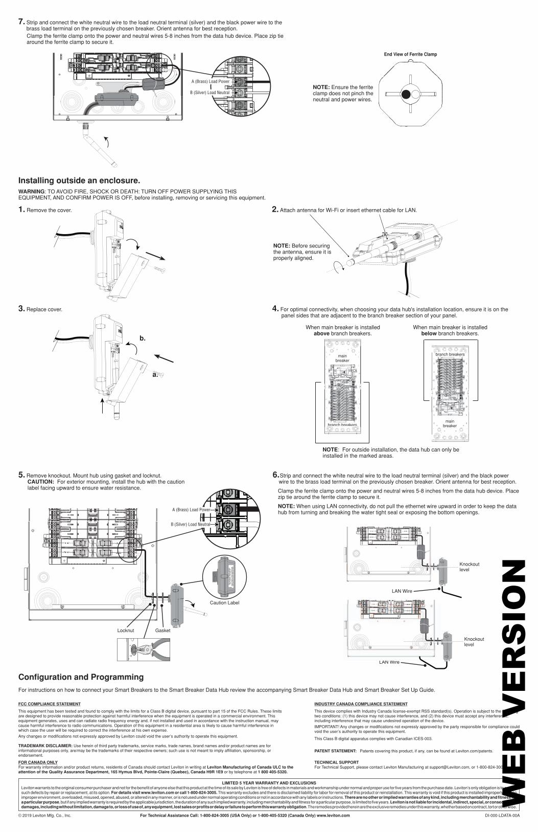
7. Strip and connect the white neutral wire to the load neutral terminal (silver) and the black power wire to the brass load terminal on the previously chosen breaker. Orient antenna for best reception.
Clamp the ferrite clamp onto the power and neutral wires 5-8 inches from the data hub device. Place zip tie around the ferrite clamp to secure it.
6. Strip and connect the white neutral wire to the load neutral terminal (silver) and the black power wire to the brass load terminal on the previously chosen breaker. Orient antenna for best reception.
Clamp the ferrite clamp onto the power and neutral wires 5-8 inches from the data hub device. Place zip tie around the ferrite clamp to secure it.
NOTE: When using LAN connectivity, do not pull the ethernet wire upward in order to keep the data hub from turning and breaking the water tight seal or exposing the bottom openings.
A (Brass) Load Power
B (Silver) Load Neutral
Installing outside an enclosure.WARNING: TO AVOID FIRE, SHOCK OR DEATH: TURN OFF POWER SUPPLYING THIS EQUIPMENT, AND CONFIRM POWER IS OFF, before installing, removing or servicing this equipment.
3. Replace cover. 4. For optimal connectivity, when choosing your data hub's installation location, ensure it is on the panel sides that are adjacent to the branch breaker section of your panel.
5. Remove knockout. Mount hub using gasket and locknut. CAUTION: For exterior mounting, install the hub with the caution label facing upward to ensure water resistance.
a.
b.
1. Remove the cover.
Configuration and Programming
For instructions on how to connect your Smart Breakers to the Smart Breaker Data Hub review the accompanying Smart Breaker Data Hub and Smart Breaker Set Up Guide.
Gasket
Knockout level
Knockout level
LAN Wire
LAN Wire
Locknut
Caution Label
A (Brass) Load Power
B (Silver) Load Neutral
LAN Wi
2. Attach antenna for Wi-Fi or insert ethernet cable for LAN.
NOTE: Before securing the antenna, ensure it is properly aligned.
End View of Ferrite Clamp
NOTE: For outside installation, the data hub can only be installed in the marked areas.
When main breaker is installed above branch breakers.
When main breaker is installed below branch breakers.
main breaker
branch breakersmain
breaker
branch breakers
PATENT STATEMENT: Patents covering this product, if any, can be found at Leviton.com/patents.
NOTE: Ensure the ferrite clamp does not pinch the neutral and power wires.
WE
B V
ER
SIO
N