catalog air handling unit - vortice ventilation, fans and air ... air handling unit - vortice...
TRANSCRIPT
VorticeAir treatment
2
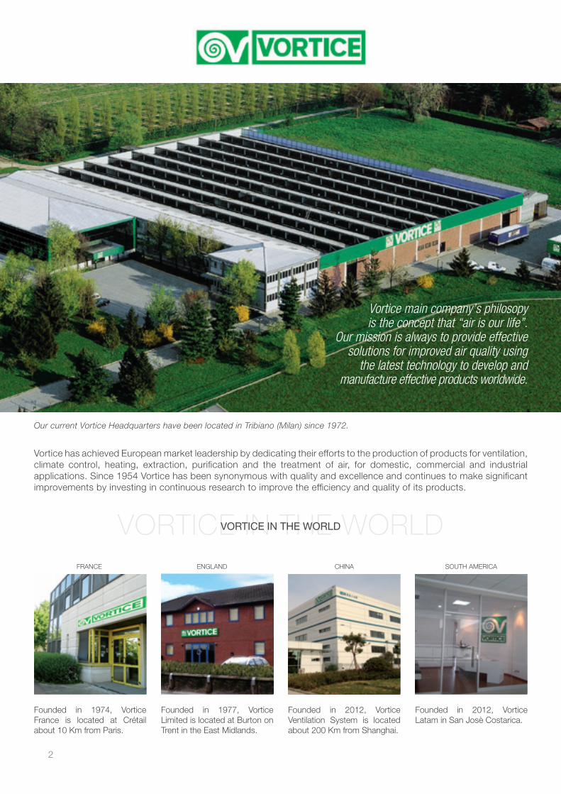
Vortice has achieved European market leadership by dedicating their efforts to the production of products for ventilation, climate control, heating, extraction, purification and the treatment of air, for domestic, commercial and industrial applications. Since 1954 Vortice has been synonymous with quality and excellence and continues to make significant improvements by investing in continuous research to improve the efficiency and quality of its products.
Our current Vortice Headquarters have been located in Tribiano (Milan) since 1972.
VORTICE IN THE WORLDVORTICE IN THE WORLD
Founded in 1977, Vortice Limited is located at Burton on Trent in the East Midlands.
ENGLAND
Founded in 2012, Vortice Ventilation System is located about 200 Km from Shanghai.
CHINA
Founded in 2012, Vortice Latam in San Josè Costarica.
SOUTH AMERICAFRANCE
Founded in 1974, Vortice France is located at Crétail about 10 Km from Paris.
Vortice main company’s philosopy is the concept that “air is our life”.
Our mission is always to provide effective solutions for improved air quality using
the latest technology to develop and manufacture effective products worldwide.
3
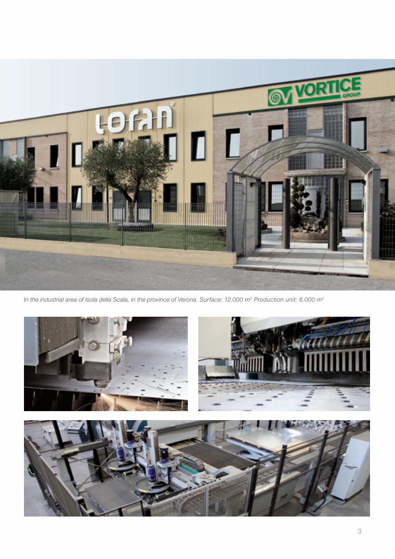
In the industrial area of Isola della Scala, in the province of Verona. Surface: 12.000 m2 Production unit: 6.000 m2


We are working to contributewell- being to people and
also environmental protectionby developing, manufacturing and
supplying products fitted to commercialand industrial application in accordance
of the environment and a people.
Better Air Better Life

AIR TREATMENT
6

7
INDEX
AIR TREATMENT
08 AIR HANDLING UNITS CTL
26 MICRO AIR HANDLING UNITS MCL
50 SANITARY UNITS STEEL CLEAN
52 SANITARY UNITS FOR FOOD INDUSTRY PRO CLEAN
110 DIRECTLY COUPLED THERMOVENTILATING UNITS TVL-DD
128 HIGH EFFICIENCY UNITS HRL

AIR TREATMENT
8
CTLAir handling units special execution for higher air volumes
PRODUCT SPECIFICATIONS
This catalogue represents a summary of the CTL series air handling units, illustrating their main characteristics.
The purpose is to describe the standard range, while at the same time highlighting the flexibility and best technical solutions possible for meeting different needs on site. Loran air handling units make an important contribution
to improving air quality and the environments we live in. The company is constantly committed to research and development of environmentally-sustainable products with maximum energy efficiency. Constructional quality and the components used
guarantee reliability, functionality and efficiency that last over time. The CTL units are available in 32 sizes, covering a vast
range of air flows, and are designed using a simple and flexible modular system.
CE marking All VORTICE air handling units are built in compliance with
Machinery Directive 2006/42/EC, Low Voltage Directive 2006/95/EC, and Electromagnetic Compatibility Directive 2004/108/EC, and consequently conform to the “essential health and safety requirements” defined by such Directives. The design work is develped respecting these standards and to this end the machines are equipped with a series of prevention and safety features suitable for satisfying the obligatory requirements:
- accident prevention protection grills over moving parts; - safety micro-switches; - lights for illuminating the inside of the machines; - handles that open also from inside the machine; - rounded edges and no parts that cut. Adhesive signs - clearly visible because of their colour and
size are applied to the external casings of the machine indicating possible dangers from moving parts and the electric current present.
CERTIFICATION
9
CTK
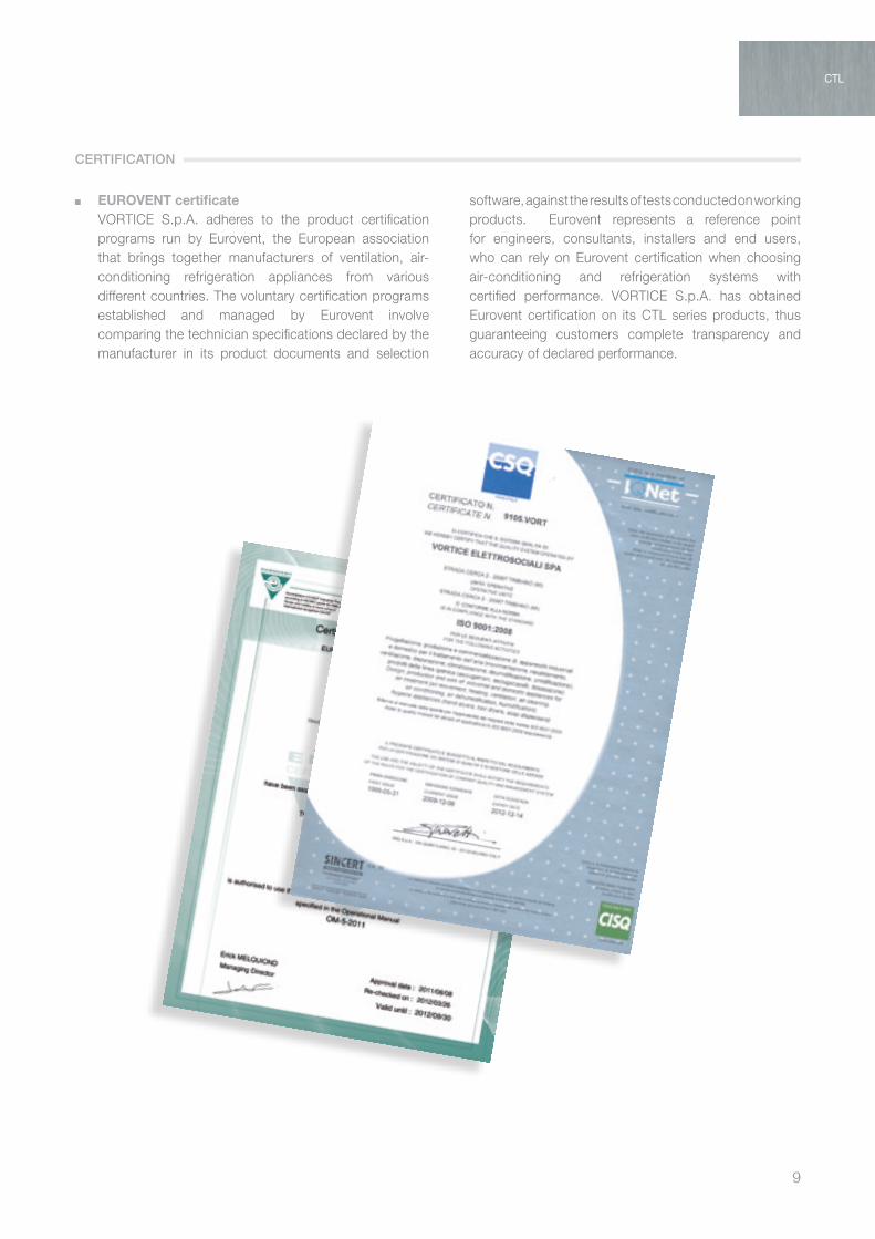
EUROVENT certificate VORTICE S.p.A. adheres to the product certification
programs run by Eurovent, the European association that brings together manufacturers of ventilation, air-conditioning refrigeration appliances from various different countries. The voluntary certification programs established and managed by Eurovent involve comparing the technician specifications declared by the manufacturer in its product documents and selection
software, against the results of tests conducted on working products. Eurovent represents a reference point for engineers, consultants, installers and end users, who can rely on Eurovent certification when choosing air-conditioning and refrigeration systems with certified performance. VORTICE S.p.A. has obtained Eurovent certification on its CTL series products, thus guaranteeing customers complete transparency and accuracy of declared performance.
CTL
CERTIFICATION

AIR TREATMENT
10
Air handling units are sized by selecting the components that meet the system’s thermo-mechanical design requirements. The unit is selected according to air flow and air velocity through the coils.The following values are recommended:
ventilation section (no filters, no heat exchangers) max 4,0 m/sec heating coil max 3,5 m/seccooling coil max 2,8 m/sec
The CTL range is available in 32 sizes for nominal air flow from 1,000 to 100,000 m3/h.
The tables show the possible choices based on these two main parameters.
0
CTL 020
Air volume m³/h
1000
4000
6000
1000
0
2000
3000
5000
8000
CTL 030
CTL 040
CTL 050
CTL 060
CTL 070
CTL 080
1200
0
1400
0
1800
0
1600
0
2000
0
2200
0
2400
0
2600
0
2800
0
CTL 100
CTL 120
CTL 140
CTL 160
CTL 170
CTL 200
CTL 220
speed on battery
2.0 2.5 3.0 3.5
0
CTL 240
Air volume m³/h
CTL 250
CTL 270
CTL 300
CTL 340
CTL 350
CTL 360
CTL 380
CTL 450
CTL 480
CTL 510
CTL 530
CTL 570
CTL 600
1000
0
2000
0
3000
0
4000
0
5000
0
6000
0
7000
0
8000
0
9000
0
1000
00
1100
00
1200
00
1300
00
1400
00
CTL 700
CTL 800
CTL 900
CTL 1000
0
CTL 020
Air volume m³/h
1000
4000
6000
1000
0
2000
3000
5000
8000
CTL 030
CTL 040
CTL 050
CTL 060
CTL 070
CTL 080
1200
0
1400
0
1800
0
1600
0
2000
0
2200
0
2400
0
2600
0
2800
0
CTL 100
CTL 120
CTL 140
CTL 160
CTL 170
CTL 200
CTL 220
speed on battery
2.0 2.5 3.0 3.5
0
CTL 240
Air volume m³/h
CTL 250
CTL 270
CTL 300
CTL 340
CTL 350
CTL 360
CTL 380
CTL 450
CTL 480
CTL 510
CTL 530
CTL 570
CTL 600
1000
0
2000
0
3000
0
4000
0
5000
0
6000
0
7000
0
8000
0
9000
0
1000
00
1100
00
1200
00
1300
00
1400
00
CTL 700
CTL 800
CTL 900
CTL 1000
SIZE
11
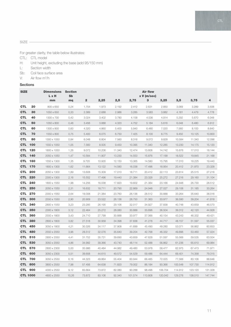
For greater clarity, the table below illustrates:CTL: CTL modelH: Unit height, excluding the base (add 95/150 mm)L: Section widthSb: Coil face surface areaV: Air flow m3/h
Sections
SIZE Dimensions Section Air flow L x H Sb x V (m/sec) mm mq 2 2,25 2,5 2,75 3 3,25 3,5 3,75 4
CTL 20 800 x 650 0,24 1.754 1.973 2.192 2.412 2.631 2.850 3.069 3.289 3.508
CTL 30 1050 x 650 0,33 2.389 2.688 2.986 3.285 3.583 3.882 4.181 4.479 4.778
CTL 40 1300 x 700 0,42 3.024 3.402 3.780 4.158 4.536 4.914 5.292 5.670 6.048
CTL 50 1050 x 800 0,48 3.456 3.888 4.320 4.752 5.184 5.616 6.048 6.480 6.912
CTL 60 1300 x 800 0,60 4.320 4.860 5.400 5.940 6.480 7.020 7.560 8.100 8.640
CTL 70 1550 x 800 0,75 5.400 6.075 6.750 7.425 8.100 8.775 9.450 10.125 10.800
CTL 80 1300 x 1050 0,84 6.048 6.804 7.560 8.316 9.072 9.828 10.584 11.340 12.096
CTL 100 1550 x 1050 1,05 7.560 8.505 9.450 10.395 11.340 12.285 13.230 14.175 15.120
CTL 120 1800 x 1050 1,26 9.072 10.206 11.340 12.474 13.608 14.742 15.876 17.010 18.144
CTL 140 2050 x 1050 1,47 10.584 11.907 13.230 14.553 15.876 17.199 18.522 19.845 21.168
CTL 160 1550 x 1300 1,35 9.720 10.935 12.150 13.365 14.580 15.795 17.010 18.225 19.440
CTL 170 1800 x 1300 1,62 11.664 13.122 14.580 16.038 17.496 18.954 20.412 21.870 23.328
CTL 200 2050 x 1300 1,89 13.608 15.309 17.010 18.711 20.412 22.113 23.814 25.515 27.216
CTL 220 2300 x 1300 2,16 15.552 17.496 19.440 21.384 23.328 25.272 27.216 29.160 31.104
CTL 240 1800 x 1550 1,98 14.256 16.038 17.820 19.602 21.384 23.166 24.948 26.730 28.512
CTL 250 2050 x 1550 2,31 16.632 18.711 20.790 22.869 24.948 27.027 29.106 31.185 33.264
CTL 270 2300 x 1550 2,64 19.008 21.384 23.760 26.136 28.512 30.888 33.264 35.640 38.016
CTL 300 2550 x 1550 2,90 20.909 23.522 26.136 28.750 31.363 33.977 36.590 39.204 41.818
CTL 340 2800 x 1550 3,23 23.285 26.195 29.106 32.017 34.927 37.838 40.748 43.659 46.570
CTL 350 2300 x 1800 3,12 22.464 25.272 28.080 30.888 33.696 36.504 39.312 42.120 44.928
CTL 360 2550 x 1800 3,43 24.710 27.799 30.888 33.977 37.066 40.154 43.243 46.332 49.421
CTL 380 2800 x 1800 3,82 27.518 30.958 34.398 37.838 41.278 44.717 48.157 51.597 55.037
CTL 450 3050 x 1800 4,21 30.326 34.117 37.908 41.699 45.490 49.280 53.071 56.862 60.653
CTL 480 2550 x 2050 3,96 28.512 32.076 35.640 39.204 42.768 46.332 49.896 53.460 57.024
CTL 510 2800 x 2050 4,41 31.752 35.721 39.690 43.659 47.628 51.597 55.566 59.535 63.504
CTL 530 3050 x 2050 4,86 34.992 39.366 43.740 48.114 52.488 56.862 61.236 65.610 69.984
CTL 570 2800 x 2300 5,00 35.986 40.484 44.982 49.480 53.978 58.477 62.975 67.473 71.971
CTL 600 3050 x 2300 5,51 39.658 44.615 49.572 54.529 59.486 64.444 69.401 74.358 79.315
CTL 700 3050 x 2550 6,16 44.323 49.864 55.404 60.944 66.485 72.025 77.566 83.106 88.646
CTL 800 3800 x 2550 7,98 57.456 64.638 71.820 79.002 86.184 93.366 100.548 107.730 114.912
CTL 900 4300 x 2550 9,12 65.664 73.872 82.080 90.288 98.496 106.704 114.912 123.120 131.328
CTL 1000 4800 x 2550 10,26 73.872 83.106 92.340 101.574 110.808 120.042 129.276 138.510 147.744
CTL
SIZE
AIR TREATMENT
12
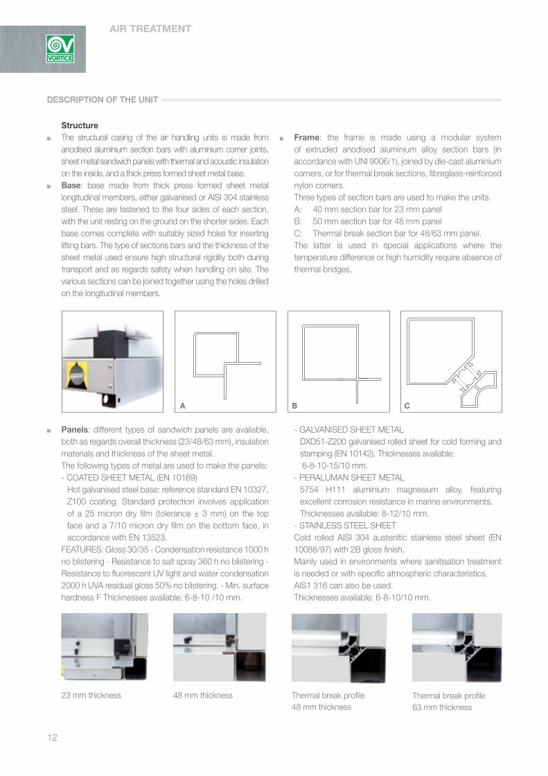
Structure The structural casing of the air handling units is made from
anodised aluminium section bars with aluminium corner joints, sheet metal sandwich panels with thermal and acoustic insulation on the inside, and a thick press formed sheet metal base.
Base: base made from thick press formed sheet metal longitudinal members, either galvanised or AISI 304 stainless steel. These are fastened to the four sides of each section, with the unit resting on the ground on the shorter sides. Each base comes complete with suitably sized holes for inserting lifting bars. The type of sections bars and the thickness of the sheet metal used ensure high structural rigidity both during transport and as regards safety when handling on site. The various sections can be joined together using the holes drilled on the longitudinal members.
Frame: the frame is made using a modular system of extruded anodised aluminium alloy section bars (in accordance with UNI 9006/1), joined by die-cast aluminium corners, or for thermal break sections, fibreglass-reinforced nylon corners.
Three types of section bars are used to make the units. A: 40 mm section bar for 23 mm panel B: 50 mm section bar for 48 mm panel C: Thermal break section bar for 48/63 mm panel. The latter is used in special applications where the
temperature difference or high humidity require absence of thermal bridges.
Panels: different types of sandwich panels are available, both as regards overall thickness (23/48/63 mm), insulation materials and thickness of the sheet metal.
The following types of metal are used to make the panels: - COATED SHEET METAL (EN 10169) Hot galvanised steel base: reference standard EN 10327,
Z100 coating. Standard protection involves application of a 25 micron dry film (tolerance ± 3 mm) on the top face and a 7/10 micron dry film on the bottom face, in accordance with EN 13523.
FEATURES: Gloss 30/35 - Condensation resistance 1000 h no blistering - Resistance to salt spray 360 h no blistering - Resistance to fluorescent UV light and water condensation 2000 h UVA residual gloss 50% no blistering. - Min. surface hardness F Thicknesses available: 6-8-10 /10 mm.
- GALVANISED SHEET METAL DXD51-Z200 galvanised rolled sheet for cold forming and
stamping (EN 10142). Thicknesses available: 6-8-10-15/10 mm. - PERALUMAN SHEET METAL 5754 H111 aluminium magnesium alloy, featuring
excellent corrosion resistance in marine environments. Thicknesses available: 8-12/10 mm.
- STAINLESS STEEL SHEET Cold rolled AISI 304 austenitic stainless steel sheet (EN
10088/97) with 2B gloss finish. Mainly used in environments where sanitisation treatment
is needed or with specific atmospheric characteristics. AIS1 316 can also be used. Thicknesses available: 6-8-10/10 mm.
A B C
23 mm thickness 48 mm thickness Thermal break profile48 mm thickness
Thermal break profile63 mm thickness
DESCRIPTION OF THE UNITDESCRIPTION OF THE UNIT

13
CTK
Internal insulation: the following types of thermal and acoustic insulation can be used:
- Polyurethane foam, density 40+/-5 kg/m3, thermal conductivity 0.022 (W/mk). Reaction to fire in accordance with ISO 3582 DIN 4102:B3.
- Mineral wool, as well as being a natural material with good thermal insulation properties, has an open cell structure that makes it an excellent soundproofing material; indeed it combines five fundamental features, including thermal-acoustic insulation and excellent reaction to fire. Density 90/100 kg/m3, thermal conductivity 0.045 (W/mk).
Sound attenuation
23 mm polyurethane foam panel
Frequency Hz 63 125 250 500 1000 2000 4000 8000Sound attenuation dB 2 9 9 11 12 12 22 30
48 mm polyurethane foam panel
Frequency Hz 63 125 250 500 1000 2000 4000 8000Sound attenuation dB 3 9 9 11 13 12 26 32
23 mm mineral wool panel
Frequency Hz 63 125 250 500 1000 2000 4000 8000Sound attenuation dB 2 13 16 24 23 23 22 30
48 mm mineral wool panel
Frequency Hz 63 125 250 500 1000 2000 4000 8000Sound attenuation dB 4 13 18 24 24 23 26 30
63 mm mineral wool panel
Frequency Hz 63 125 250 500 1000 2000 4000 8000Sound attenuation dB 4 16 21 27 27 28 31 39
CTK
Rain cover: required for installations outside of the equipment room, made from:
- coated sheet metal, 6/10 mm thick - galvanised sheet metal, 6/10 mm thick - Peraluman sheet metal, 8/10 mm thick Secured directly onto the sections using suitably insulated
and sealed screws.
CTK
CTK
CTL
DESCRIPTION OF THE UNIT
AIR TREATMENT
14
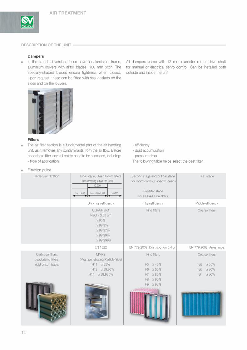
Molecular filtration Final stage, Clean Room filters Second stage and/or final stage First stage
for rooms without specific needs
Pre-filter stage
for HEPA/ULPA filters
Ultra high efficiency High efficiency Middle efficiency
ULPA/HEPA Fine filters Coarse filters
NaCl - 0,65 um
≥ 95%
≥ 99,9%
≥ 99,97%
≥ 99,99%
≥ 99,999%
EN 1822 EN 779:2002, Dust spot on 0.4 um EN 779:2002, Arrestance
Cartridge filters, MMPS Fine filters Coarse filters
deodorising filters, (Most penetrating Particle Size)
rigid or soft bags. H11 ≥ 95% F5 ≥ 40% G2 ≥ 65%
H13 ≥ 99,95% F6 ≥ 60% G3 ≥ 80%
H14 ≥ 99,995% F7 ≥ 80% G4 ≥ 90%
F8 ≥ 90%
F9 ≥ 95%
Dampers In the standard version, these have an aluminium frame,
aluminium louvers with airfoil blades, 100 mm pitch. The specially-shaped blades ensure tightness when closed. Upon request, these can be fitted with seal gaskets on the sides and on the louvers.
All dampers came with 12 mm diameter motor drive shaft for manual or electrical servo control. Can be installed both outside and inside the unit.
Filters The air filter section is a fundamental part of the air handling
unit, as it removes any contaminants from the air flow. Before choosing a filter, several points need to be assessed, including:
- type of application
Filtration guide
- efficiency - dust accumulation - pressure drop The following table helps select the best filter.
Class according to Fed. Std 209 E
10.000
from 1 to 10 from 100 to 1.000 100.000
DESCRIPTION OF THE UNIT

15
CTK
Middle efficiency filters: Middle efficiency or coarse filters are used as the first or second filter stage.
Filter class in accordance with EN 779-2002: G2 Weighted average efficiency ≥ 65% G3 Weighted average efficiency ≥ 80% G4 Weighted average efficiency ≥ 90%
Type of filters: G2 Corrugated mesh filter cells (stainless/galvanised steel) G3 Drum filter with progressive density synthetic media G4 Corrugated filter cells with synthetic media,
galvanised steel frame, welded galvanised steel wire protective grill.
High efficiency filters: High efficiency filters or fine filters are used as the second or final filter stage in places without specific needs. Also used as pre-filters for HEPA / ULPA.
Filter class in accordance with EN 779-2002: F5 Average dust spot efficiency ≥ 40% F6 Average dust spot efficiency ≥ 60% F7 Average dust spot efficiency ≥ 80% F8 Average dust spot efficiency ≥ 90% F9 Average dust spot efficiency ≥ 95%
Type of filters: F5 - Corrugated filter cells with synthetic media, galvanised
steel frame, welded galvanised steel wire protective grill. Recommended maximum pressure drop 200 Pa. - Soft pocket filters with large glass fibre filtering surface. Galvanised steel frame. Recommended maximum pressure drop 250 Pa. F6 / F7 / F9 (fig. 2) - Soft pocket filters with large glass fibre filtering surface. Galvanised steel frame Length 380 mm. Upon request the filtering surface area can be increased
by extending the length of the filter to 535 or 635 mm. Recommended pressure drop 250 Pa. - Rigid glass fibre pocket filter, polypropylene/ABS frame. Recommended maximum pressure drop 250 Pa (fig. 1).
Ultra high efficiency filters: Ultra high efficiency filters are used as the final stage to ensure high air purity. Mainly installed in places that need to remain aseptic, such as clean rooms, hospital environments, pharmaceutical or electronics facilities. The type of installation of these filters is essential, being housed in special galvanised or stainless steel frames fitted with gaskets to ensure the filter is not bypassed (fig. 3).
Filter class in accordance with EN 1822: H 11 Efficiency ≥ 95% H 13 Efficiency ≥99.95% H 14 Efficiency ≥ 99.995%
H 11 / 13 / 14 Absolute HEPA filter, galvanised steel frame and micron-
sized glass fibre filter media. Recommended maximum pressure drop 600 Pa.
Molecular filtration: These filters were originally designed for trapping gaseous pollutants (molecules) such as vehicle exhausts, industrial emissions from combustion processes or simple cigarette smoke.
Their trapping capacity depends on the type of molecule being filtered.
Can be used in combination with dust filters.
Type: - Soft pocket with activated carbon for double action:
filtration of dust (EN 779 filtration class F7) and gaseous pollutants. Installed to replace existing pocket filters, with no further filtering systems required. Made from glass fibre media plus activated carbon.
- Rigid pocket with activated carbon for double action: filtration of dust (EN 779 filtration class F7) and gaseous pollutants. Installed to replace existing pocket filters, with no further filtering systems required. Made from glass fibre media plus activated carbon (fig. 4).
- Cartridges containing activated carbon, ideal for service and industrial applications where deodorising is required. Fitted on galvanised metal plates with bayonet mount (fig. 5).
fig. 1 fig. 2 fig. 3 fig. 4 fig. 5
CTL
DESCRIPTION OF THE UNIT

AIR TREATMENT
16
Heat exchange coils Heat exchange coils are the principal elements bringing about
changes in air temperature and humidity. Heat exchange is indirect; a primary fluid such as hot or cold water, or hot or cold gas that flows through the coils interacts with the secondary fluid, in this case the process air. The coils are finned tubes made from different materials with continuous fins featuring a collar to adjust and evenly space the fins. The tubes are mechanically expanded to ensure perfect coupling between tube and fin and consequently perfect heat exchange. The fins have a corrugated surface to ensure rigidity and create air turbulence, increasing the heat exchange coefficient. All coils can be removed both from the side with fittings and the opposite side. The heat exchanger construction materials are chosen based on the primary and secondary fluids; the following options are available:
Materials Copper tube Aluminium fins Copper tube Copper fins Copper tube Tinned copper fins Copper tube Coated aluminium fins Iron tube Aluminium fins Stainless steel tube Aluminium fins Stainless steel tube Stainless steel fins
Configurations PT 60 60x30 ø 5/8 tube PT 30 30x30 ø 5/8 tube PT 30 30x26 ø 3/8 tube PT 40 40x30 ø 5/8 tube
Fin pitch mm 1,8 2,0 2,5 3,0 4,0 5,0 6,0
Operation Hot water Cold water Superheated water Steam Direct expansion of Freon Condensation of Freon
The number of rows, circuit configuration and materials can be easily determined using the VORTICE selection program and with the help of the company’s technical department.
When sizing the unit, as well as air velocity, a number of minimum and maximum limits also been to be taken into account, based on experience and practical considerations.
TYPE OF PROCESS MINIMUM LIMIT MAXIMUM LIMIT m/sec m/sec
Cooling and condensation without droplet separator 1.6 2.5
Cooling and condensation with droplet separator 1.6 3.2
Heating 1.6 4.1
DESCRIPTION OF THE UNIT

17
Electric coils: electric coils are made from finned tubular air heating elements with single- or multi-stage operation.
The standard configuration features iron tubes and galvanised iron fins, the heating elements are fastened to a galvanised sheet metal sheath by insulated bushes complete with vibration-damping gasket.
Complete with mechanical thermoregulator with two changeover contacts, range 20°/120°C.
Power supply 400 V 3 Phase 50 Hz. Terminal block protection IP 55.
For correct operation, air velocity must not be less than 2.6 m/sec.
The electric coil should be installed downstream of the fan to avoid overheating the motor.
If used in humid environments with steam production or frequent washing, the heater contacts can be sealed for protection.
A wide range of heat outputs is available, depending on the type of process performed.
Coil dimensions
SIZE Section Coil dimensions 60x30 30x30 30x26 40x30 dimensions config. config. config. config. base x height W x H section tubes tubes tubes tubes 50 mm rhick mq
CTL 20 800 x 650 580 x 420 0,24 7 14 14 10
CTL 30 1050 x 650 790 x 420 0,33 7 14 14 10
CTL 40 1300 x 700 1000 x 420 0,42 7 14 14 10
CTL 50 1050 x 800 800 x 600 0,48 10 20 20 15
CTL 60 1300 x 800 1000 x 600 0,60 10 20 20 15
CTL 70 1550 x 800 1250 x 600 0,75 10 20 20 15
CTL 80 1300 x 1050 1000 x 840 0,84 14 28 28 21
CTL 100 1550 x 1050 1250 x 840 1,05 14 28 28 21
CTL 120 1800 x 1050 1500 x 840 1,26 14 28 28 21
CTL 140 2050 x 1050 1750 x 840 1,47 14 28 28 21
CTL 160 1550 x 1300 1250 x 1080 1,35 18 36 36 27
CTL 170 1800 x 1300 1500 x 1080 1,62 18 36 36 27
CTL 200 2050 x 1300 1750 x 1080 1,89 18 36 36 27
CTL 220 2300 x 1300 2000 x 1080 2,16 18 36 36 27
CTL 240 1800 x 1550 1500 x 1320 1,98 22 44 44 33
CTL 250 2050 x 1550 1750 x 1320 2,31 22 44 44 33
CTL 270 2300 x 1550 2000 x 1320 2,64 22 44 44 33
CTL 300 2550 x 1550 2200 x 1320 2,90 22 44 44 33
CTL 340 2800 x 1550 2450 x 1320 3,23 22 44 44 33
CTL 350 2300 x 1800 2000 x 1560 3,12 26 52 52 39
CTL 360 2550 x 1800 2200 x 1560 3,43 26 52 52 39
CTL 380 2800 x 1800 2450 x 1560 3,82 26 52 52 39
CTL 450 3050 x 1800 2700 x 1560 4,21 26 52 52 39
CTL 480 2550 x 2050 2200 x 1800 3,96 30 60 60 45
CTL 510 2800 x 2050 2450 x 1800 4,41 30 60 60 45
CTL 530 3050 x 2050 2700 x 1800 4,86 30 60 60 45
CTL 570 2800 x 2300 2450 x 2040 5,00 34 68 68 51
CTL 600 3050 x 2300 2700 x 2040 5,51 34 68 68 51
CTL 700 3050 x 2550 2700 x 2280 6,16 38 76 76 57
CTL 800 3800 x 2550 3500 x 2280 7,98 38 76 76 57
CTL 900 4300 x 2550 4000 x 2280 9,12 38 76 76 57
CTL 1000 4800 x 2250 4500 x 2280 10,26 38 76 76 57
DESCRIPTION OF THE UNIT
CTL

AIR TREATMENT
18
Humidifier sections Air humidification plays a fundamental role in normal air-
conditioning processes, as the humidity level needs to be kept constant to ensure personal comfort in air-conditioned spaces.
The most common solutions are: - Adiabatic humidification with wetted media - Water spray humidification with one or two nozzle racks - Steam humidification The features of each are described below.
Wetted media humidifier Evaporative humidification uses specially-shaped wetted
media with a honeycomb-like structure, made from sheets of resin-impregnated absorbent paper to ensure the right consistency and structural strength, protect against decomposition and prevent mould formation. The media is formed using sheets of cross corrugated cellulose glued together using atoxic adhesives; no phenolic resins are used. This arrangement ensures a large contact surface between the air and water, meaning high efficiency. The operating principle is simple, and involves uniformly wetting the media using a special distribution system to avoid dry areas that would cause a decline in efficiency. The air flowing through the media is humidified and cooled to an extent that varies depending on the conditions.
Main features of the cellulose media include: - Excellent efficiency - Low pressure drop - Low running costs - Fast installation
To achieve good efficiency and correct hygiene, the conditions of the humidifier sections in civil air-conditioning systems need to be checked periodically.
The following types of application are available: - 100 mm honeycomb media with once-through water - 200 mm honeycomb media with once-through water - 100 mm honeycomb media with recirculating pump - 200 mm honeycomb media with recirculating pump
Efficiency
Water spray humidifier with one or two nozzle racks Adiabatic humidifier made up of a series of spray nozzles
operating at low pressure, supplied via a manifold connected to the water mains or a pumping system. This type of humidifier can also be used for evaporative cooling or as a washer. In this case, two rows of nozzles are used with flow in both the same and the opposite directions, creating turbulence that causes the dust to precipitate.These systems have a multitude of applications; naturally, demineralised water must be used for sterile and aseptic environments. Main features of the spray system include:
- Reasonably good efficiency - Low pressure drop - Low running costs
The following types of application are available: Low pressure nozzles - Humidifier with 1 low press. nozzle rack and once-through water - Humidifier with 2 low press. nozzle racks and once-through water - Humidifier with 1 low press. nozzle rack and recirculating pump - Humidifier with 2 low press. nozzle racks and recirculating pump
100 200
2,0
1,5
2,5
3,0
Air
velo
city
V (m
/s)
50 60 70 80 90 100Efficiency Ue (%)
Wetted media humidifier Water spray humidifier
DESCRIPTION OF THE UNIT

19
CTK
Spray humidification efficiency
Atomising humidifier (fig. 6): this type of humidifier represents a new generation of economical appliances, with power consumption of just 4 watts for each l/h of water atomised. Ideal for all applications where high humidification capacities are required, up to 500 kg/h. The appliance uses a special pump to deliver water at high pressure through stainless steel nozzles and produce a very fine and uniform fog. The droplets generated then spontaneously evaporate, humidifying and cooling the air. This air/water system does not require the use of a compressor or installation of a compressed air line. In addition, as a further guarantee of hygiene, the appliance does not atomise recirculated water, in compliance with the main international guidelines and standards (ASHRAE 12-2000, VDI6022, VDI3803, L8).
EFFICIENCY: Absorption efficiency is 85-87%.
Steam humidifier: isothermal humidifier made using one or more perforated stainless steel steam pipes, complete with additional concentric pipes for draining condensate.
The humidifier section is sized to ensure maximum air/steam interaction. Main features of the steam system include: - Very high efficiency - Low pressure drop - Multiple applications - Easy to install Naturally, running costs are regards energy consumption
are higher when compared against the systems described previously.
This type of humidifier can be supplied as follows: - unit configured for humidifier installation by the customer - steam distributor only (if a source of steam is already available) - distribution system and immersed electrode steam generator
EFFICIENCY: Efficiency is around 90%.
Droplet separators (fig. 7) These are designed to trap as many droplets of water as
possible generated inside the unit by air dehumidification or humidification systems. These must be installed:
- when the air velocity across the cooling coil exceeds 2.5 m/sec - downstream of all the humidification systems described previously - in certain applications downstream of plate heat recovery
exchangers where a high amount of condensation takes place
The following materials and types can be selected: - 2 changes in direction, extruded polypropylene - 4 changes in direction, extruded polypropylene - 2 changes in direction, extruded aluminium - 3 changes in direction, press formed stainless steel sheet
Drain tank Condensate collection tanks are provided near the
following components: Cooling coil - Heat recovery coils - Cross-flow heat recovery units - Heat wheels - Humidifier sections - Droplet separators Made from thick press formed and welded AISI 304/316 stainless steel or galvanised iron sheet. Featuring drain opening and hose connector to simplify water connection on site. For sanitisable air handling units, tanks are provided with higher inclines to assist complete drainage of the water (fig. 8).
2,0
1,5
2,5
3,0
Air
velo
city
V (m
/s)
10 20 30 40 50 60Efficiency Ue (%)
fig. 6 fig. 7 fig.8
CTL
DESCRIPTION OF THE UNIT

AIR TREATMENT
20
Heat recovery units Heat recovery units are widely used to partially recover
waste or exhaust energy, bringing significant savings in system running costs. The following types are available:
- Plate heat recovery exchangers - Heat wheels - Heat recovery coils - Heat pipe heat exchangers (contact the technical department for sizing)
Plate heat recovery exchangers: plate heat recovery units are heat exchangers that transfer heat between two air flows due to the difference in temperature. These units allow significant savings in running costs of air-conditioning systems by recovering energy that otherwise would be lost in the form of heat.
Essential features - low installation and running costs - complete separation of air flows - no moving parts - low pressure drop - high efficiency - easy cleaning and minimum maintenance - effective noise abatement. These can be made from aluminium, aluminium with atoxic
corrosion-resistant coating or AISI 316L stainless steel.
Heat wheels (fig. 10): rotary air-to-air heat exchangers consist of a rotating cylinder containing thousands of pockets with a very large surface area, a housing frame (comp. with brush gaskets to minimise leaks between ventilation and exhaust air flows), and a drive system made up of an electric motor with speed control where necessary.
Essential features - The very high heat exchange surface in relation to the
volume of air ensures much higher performance than other types of heat recovery units, reaching efficiency of up to 85%.
- This high efficiency plus the possibility to recovery moisture as well as heat (enthalpy wheel) mean the capacity of the units installed can be reduced considerably.
- Possibility to transfer heat latent.
- Low pressure drop. Can be made from aluminium or aluminium with atoxic coating.
Enthalpy wheels can be supplied for the recovery of latent heat.
Heat recovery coils: these are made in the same way as normal heat exchange coils, installed in the exhaust air and fresh air sections and connected via a circulating pump, generally with a water-glycol mix, creating heat exchange with efficiency less than 50%. These units are mainly used in environments where there must be no contamination between air flows.
Heat pipe heat exchangers: heat recovery units are made up of a heat exchanger, similar to a finned coil and generally with copper pipes and aluminium fins, divided into two adjacent sections. The pipes are filled with refrigerant (typically R134a) that changes state, from liquid to vapour and vice-versa, when the temperature changes. The partition between the sections, generally placed in the centre of the heat exchanger, separates the fresh air flow from the exhaust air. A tilt control device is available for seasonal changeover in operating mode.
Silencers Noise pollution is a problem that increasingly often needs
to be faced during the design process. Sound emissions are generated by the fans, and the only noise abatement system involves placing silencers upstream or downstream, depending on requirements. These are made from 100/200 mm thick mineral wool, protected by a layer of fabric or, on request, heat shrink plastic film, to ensure a perfect seal. The mineral wool is housed in a galvanised metal frame, with galvanised iron retaining mesh.
Baffle lengths: 700, 950, 1200, 1450, 1750, 1950 mm. Sound attenuation
fig.9 fig.10
DESCRIPTION OF THE UNIT
HZ/ Length 63 125 250 500 1000 2000 4000 8000
700 6 10 14 23 32 26 20 15
950 9 14 25 42 39 37 31 21
1200 9 15 27 44 40 39 32 21
1450 10 17 30 47 44 42 36 23
1750 12 19 35 48 47 47 42 26
1950 13 21 39 48 49 49 45 28

21
Ventilation sections These consist of: fan, motor, supports and dampers. Fans: centrifugal fans can be installed with the following
configurations: - forward curved blades - backward curved blades - backward curved without scroll (plug fan) - backward curved airfoil blades The impellers are statically and dynamically balanced in
accordance with the standards in force. Series R uses an individual sealed ball bearing ring, with lifetime lubrication, while the other versions have bearings with grease nipples. The bearings are rated for a lifespan of at least 40,000 hours. The type is selected according to the required performance, efficiency and sound emissions.
Accessories: - Painting, completely painted versions can be made upon
request. - Explosion proof configuration, with aluminium alloy,
copper or raised copper edge intake openings. - Condensate drain. - Inspection opening.
Orientation
CTL
DESCRIPTION OF THE UNIT

AIR TREATMENT
22
Ventilation sections The following tables illustrate the fans available with
reference to the size of the unit.
Size Fans with forward curved / backward curved / airfoil blades
CTL 20 225*
CTL 30 225*
CTL 40 225* 250*
CTL 50 225* 250* 315
CTL 60 225* 250* 315
CTL 70 225* 250* 315
CTL 80 250* 315 450
CTL 100 250* 315 450
CTL 120 250* 315 450
CTL 140 250* 315 450
CTL 160 250* 315 450 560
CTL 170 250* 315 450 560
CTL 200 250* 315 450 560
CTL 220 250* 315 450 560
CTL 240 250* 315 450 560 710
CTL 250 250* 315 450 560 710
CTL 270 250* 315 450 560 710
CTL 300 250* 315 450 560 710
CTL 340 250* 315 450 560 710
CTL 350 250* 315 450 560 710 800
CTL 360 250* 315 450 560 710 800
CTL 380 250* 315 450 560 710 800
CTL 450 250* 315 450 560 710 800
CTL 480 250* 315 450 560 710 800 900
CTL 510 250* 315 450 560 710 800 900
CTL 530 250* 315 450 560 710 800 900
CTL 570 250* 315 450 560 710 800 900 1000
CTL 600 250* 315 450 560 710 800 900 1000
CTL 700 250* 315 450 560 710 800 900 1000 1120
CTL 800 1120
CTL 900 * not available in the airfoil version 1120
CTL 1000 1120
DESCRIPTION OF THE UNIT

23
Sizes referring to plug fans.
Size Plug fans
CTL 20 315
CTL 30 315
CTL 40 315 355
CTL 50 315 355 400
CTL 60 315 355 400
CTL 70 315 355 400
CTL 80 315 355 400 630
CTL 100 315 355 400 630
CTL 120 315 355 400 630
CTL 140 315 355 400 630
CTL 160 315 355 400 630 800
CTL 170 315 355 400 630 800
CTL 200 315 355 400 630 800
CTL 220 315 355 400 630 800
CTL 240 315 355 400 630 800 1000
CTL 250 315 355 400 630 800 1000
CTL 270 315 355 400 630 800 1000
CTL 300 315 355 400 630 800 1000
CTL 340 315 355 400 630 800 1000
CTL 350 315 355 400 630 800 1000 1100
CTL 360 315 355 400 630 800 1000 1100
CTL 380 315 355 400 630 800 1000 1100
CTL 450 315 355 400 630 800 1000 1100
CTL 480 315 355 400 630 800 1000 1100
CTL 510 315 355 400 630 800 1000 1100
CTL 530 315 355 400 630 800 1000 1100
CTL 570 315 355 400 630 800 1000 1100
CTL 600 315 355 400 630 800 1000 1100
CTL 700 315 355 400 630 800 1000 1100
CTL 800 315 355 400 630 800 1000 1100
CTL 900 315 355 400 630 800 1000 1100
CTL 1000 315 355 400 630 800 1000 1100
CTL
DESCRIPTION OF THE UNIT
AIR TREATMENT
24
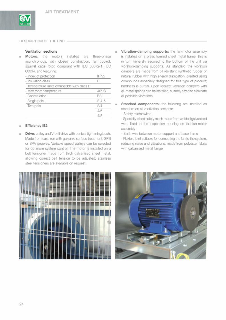
Ventilation sections Motors: the motors installed are three-phase
asynchronous, with closed construction, fan cooled, squirrel cage rotor, compliant with IEC 60072-1, IEC 60034, and featuring:
- Index of protection IP 55 - Insulation class F - Temperature limits compatible with class B - Max room temperature 40° C - Construction B3 - Single pole 2-4-6 - Two pole 2/4 4/6 4/8
Efficiency IE2
Drive: pulley and V-belt drive with conical tightening bush.Made from cast iron with galvanic surface treatment, SPB or SPA grooves. Variable speed pulleys can be selected for optimum system control. The motor is installed on a belt tensioner made from thick galvanised sheet metal, allowing correct belt tension to be adjusted; stainless steel tensioners are available on request.
Vibration-damping supports: the fan-motor assembly is installed on a press formed sheet metal frame; this is in turn generally secured to the bottom of the unit via vibration-damping supports. As standard the vibration dampers are made from oil resistant synthetic rubber or natural rubber with high energy dissipation, created using compounds especially designed for this type of product; hardness is 60°Sh. Upon request vibration dampers with all-metal springs can be installed, suitably sized to eliminate all possible vibrations.
Standard components: the following are installed as standard on all ventilation sections:
- Safety microswitch - Specially-sized safety mesh made from welded galvanised
wire, fixed to the inspection opening on the fan-motor assembly
- Earth wire between motor support and base frame - Flexible joint suitable for connecting the fan to the system,
reducing noise and vibrations, made from polyester fabric with galvanised metal flange
DESCRIPTION OF THE UNIT

25
All VORTICE air handling units can be installed with the following accessories, upon request:
- External compartments for housing valves or electrical panels, made-to-measure where required. Made from the same 23 mm sandwich panel as the air handling unit.
- Vibration damper joints on return air, fresh air inlet and ventilation air sections.
- Fresh air and return air intake grills made from aluminium with fixed louvers.
- Closed panels to be drilled on site. - IP 65 light fitting. - IP 65 light fitting with wiring. - Column pressure gauge, Magnehlic pressure gauge,
differential pressure switch. - Pressure test points. Completely wired control systems and electrical panels can
also be supplied.Testing can be performed directly on site.
CTL
ACCESSORIES

AIR TREATMENT
26
PRODUCT SPECIFICATIONS
The MCL micro air handlers are designed to respond to special system requirements where installation space is restricted and low ceiling heights areunavoidable. Application in small and medium-sized spaces with special
air-conditioning requirements. This series uses centrifugal fans coupled to electronically-
controlled single-phase motors with constant flow-rate, covering a range of system flow-rates from 1000 m3/h to 6000 m3/h.
Frame, made using a modular system of extruded anodised aluminium alloy section bars (in accordance with UNI 9006/1), joined by die-cast aluminium corners.
Sandwich panels, insulated using polyurethane foam, density 40 kg/m3, 18 mm thick. Outside panel made from coated sheet metal, 6/10 thickness with protective film, inside panel made from galvanised sheet metal, 6/10 thickness.
G4 filter, synthetic filtering media, weighted average efficiency ≥ 90% with galvanised frame and retaining mesh. Heat exchange coils suitable for heating/cooling operation,
2/4/6 rows made from 5/8” copper tube with aluminium fins and turbulators. Coils and basin removable from below. Condensate collection basin made from galvanised
sheet metal with drain at bottom and welded hose fitting. Double suction centrifugal fans with forward curved
blades, complete with programmable electronically- controlled 6-pole motor for “sensorless” constant flow- rate control. High efficiency and low noise motor driven by a 16 KHz inverter to eliminate acoustic disturbance. Single- phase power supply, 230 V 50 Hz IP 54. Insulation class F. Programming by potentiometer. Control using 0/5 Volt potentiometric signal (+5 Volt). The correspondence between potentiometric signal and flow-rate is defined when programming each fan and is based on predefined flow-rates.
Warning: Maximum operating temperature between -20°C and +40°C with air-cooled motor.
KEY FEATURES
MCLMicro air handling units horizontal execution
27
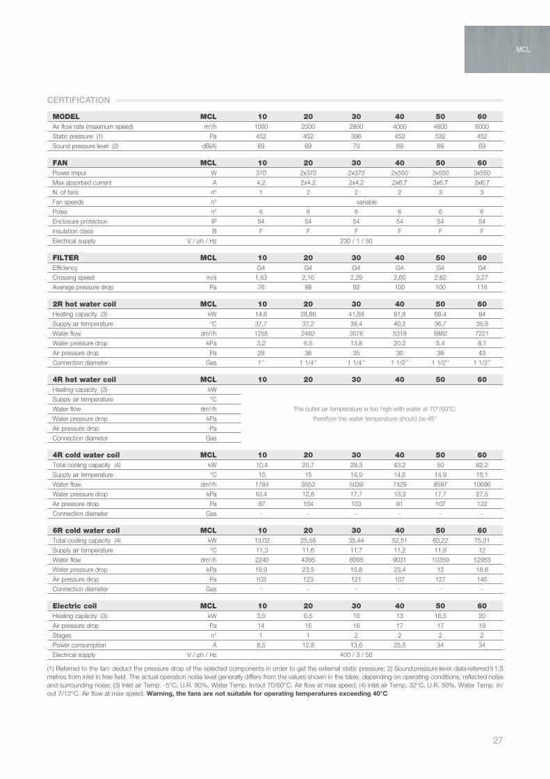
MODEL MCL 10 20 30 40 50 60Air flow rate (maximum speed) m3/h 1000 2000 2800 4000 4800 6000
Static pressure (1) Pa 452 452 396 452 532 452
Sound pressure level (2) dB(A) 69 69 70 69 69 69
FAN MCL 10 20 30 40 50 60Power imput W 370 2x370 2x370 2x550 3x550 3x550
Max absorbed current A 4,2 2x4,2 2x4,2 2x6,7 3x6,7 3x6,7
N. of fans n° 1 2 2 2 3 3
Fan speeds n° variable
Poles n° 6 6 6 6 6 6
Enclosure protection IP 54 54 54 54 54 54
Insulation class B F F F F F F
Electrical supply V / ph / Hz 230 / 1 / 50
FILTER MCL 10 20 30 40 50 60Efficiency G4 G4 G4 G4 G4 G4
Crossing speed m/s 1,63 2,16 2,29 2,60 2,62 3,27
Average pressure drop Pa 76 88 92 100 100 116
2R hot water coil MCL 10 20 30 40 50 60Heating capacity (3) kW 14,6 28,86 41,59 61,8 68,4 84
Supply air temperature °C 37,7 37,2 38,4 40,2 36,7 35,9
Water flow dm3/h 1255 2482 3576 5319 5882 7221
Water pressure drop kPa 3,2 6,5 13,8 20,2 5,4 8,1
Air pressure drop Pa 29 36 35 30 38 43
Connection diameter Gas 1’’ 1 1/4’’ 1 1/4’’ 1 1/2’’ 1 1/2’’ 1 1/2’’
4R hot water coil MCL 10 20 30 40 50 60Heating capacity (3) kW
Supply air temperature °C
Water flow dm3/h
Water pressure drop kPa
Air pressure drop Pa
Connection diameter Gas
4R cold water coil MCL 10 20 30 40 50 60Total cooling capacity (4) kW 10,4 20,7 29,3 43,2 50 62,2
Supply air temperature °C 15 15 14,9 14,5 14,9 15,1
Water flow dm3/h 1784 3552 5039 7429 8597 10696
Water pressure drop kPa 10,4 12,8 17,7 13,3 17,7 27,5
Air pressure drop Pa 87 104 103 91 107 122
Connection diameter Gas - - - - - -
6R cold water coil MCL 10 20 30 40 50 60Total cooling capacity (4) kW 13,02 25,55 35,44 52,51 60,22 75,31
Supply air temperature °C 11,3 11,6 11,7 11,2 11,9 12
Water flow dm3/h 2240 4395 6095 9031 10359 12953
Water pressure drop kPa 19,9 23,5 15,8 23,4 12 18,8
Air pressure drop Pa 103 123 121 107 127 145
Connection diameter Gas - - - - - -
Electric coil MCL 10 20 30 40 50 60Heating capacity (3) kW 3,5 6,5 10 13 16,5 20
Air pressure drop Pa 14 16 16 17 17 19
Stages n° 1 1 2 2 2 2
Power consumption A 8,5 12,8 13,6 25,5 34 34
Electrical supply V / ph / Hz 400 / 3 / 50
The outlet air temperature is too high with water at 70°/60°C,
therefore the water temperature should be 45°
MCL
CERTIFICATION
(1) Referred to the fan: deduct the pressure drop of the selected components in order to get the external static pressure; 2) Sound pressure level: data referred ti 1,5metres from inlet in free field. The actual operation noise level generally differs from the values shown in the table, depending on operating conditions, reflected noise and surrounding noise; (3) Inlet air Temp. -5°C, U.R. 80%, Water Temp. In/out 70/60°C. Air flow at max speed; (4) Inlet air Temp. 32°C, U.R. 50%, Water Temp. in/out 7/12°C. Air flow at max speed. Warning, the fans are not suitable for operating temperatures exceeding 40°C

AIR TREATMENT
28
A BB
C
D G
35H M
20
20 L 20Basic unit
Left View
MCL 50-60 Right View
MCL 10-20-30-40-50-60
Coil connections and drain
Access points
20
GR SR PA SM SILR VR CM3
FT BASE UNITS UP UV
BE BA SILM PM PMF BM
H35
D
B
GG D
B
D
35H
GG D
D
Right View MCL 10
Right ViewMCL 20-30-40
GD D
DIMESIONS
10 20 30 40 50 60
A 900 900 900 960 960 960
B 710 1070 1400 1680 1900 2000
C 380 380 380 450 450 450
D 239 168 244 308 272 336
G 232 232 232 232 232 232
H 262 262 262 262 262 262
L 670 1030 1360 1640 1740 1960
M 340 340 340 410 410 410
Dimensions (mm)
MODEL
29
A BB
C
D G
35H M
20
20 L 20Basic unit
Left View
MCL 50-60 Right View
MCL 10-20-30-40-50-60
Coil connections and drain
Access points
20
GR SR PA SM SILR VR CM3
FT BASE UNITS UP UV
BE BA SILM PM PMF BM
H35
D
B
GG D
B
D
35H
GG D
D
Right View MCL 10
Right ViewMCL 20-30-40
GD D
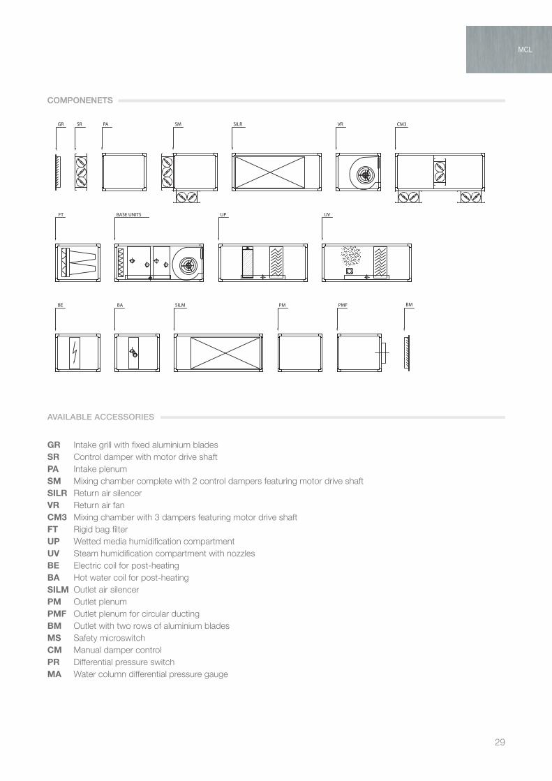
GR Intake grill with fixed aluminium bladesSR Control damper with motor drive shaftPA Intake plenumSM Mixing chamber complete with 2 control dampers featuring motor drive shaftSILR Return air silencerVR Return air fanCM3 Mixing chamber with 3 dampers featuring motor drive shaftFT Rigid bag filter UP Wetted media humidification compartmentUV Steam humidification compartment with nozzlesBE Electric coil for post-heatingBA Hot water coil for post-heatingSILM Outlet air silencerPM Outlet plenumPMF Outlet plenum for circular ductingBM Outlet with two rows of aluminium bladesMS Safety microswitchCM Manual damper controlPR Differential pressure switchMA Water column differential pressure gauge
MCL
COMPONENETSCOMPONENETS
AVAILABLE ACCESSORIES

AIR TREATMENT
30
MCL 10
Air Water 80/70°C Water 70/60°C Water 45/40°C
Volume T.i. T.u. Pot. Pw. Dp W T.u. Pot. Pw. Dp W T.u. Pot. Pw. Dp W
m3/h °C °C kW dm3/h KPa °C kW dm3/h KPa °C kW dm3/h KPa
1000 -10 43,1 18,2 1561 4,7 36 15,7 1353 3,7 22,4 11,07 1904 6,7
1000 -5 44,8 17,0 1463 4,2 37,7 14,6 1255 3,2 24,1 9,93 1708 5,6
1000 0 46,4 15,87 1365 3,7 39,4 13,46 1157 2,8 1513 8,8 1513 4,5
1000 5 48,1 14,73 1267 3,3 41 12,32 1059 2,4 27,4 7,66 1318 3,5
1000 10 49,8 13,59 1169 2,8 42,7 11,18 962 2 29,1 6,53 1123 2,6
1000 15 51,4 12,45 1071 2,4 44,4 10,05 864 1,7 30,8 5,4 929 1,9
Air Water 80/70°C Water 70/60°C Water 45/40°C
Volume T.i. T.u. Pot. Pw. Dp W T.u. Pot. Pw. Dp W T.u. Pot. Pw. Dp W
m3/h °C °C kW dm3/h KPa °C kW dm3/h KPa °C kW dm3/h KPa
1000 -10 * * * * 56,2 22,62 1945 9,7 36,1 15,75 2708 17,5
1000 -5 * * * * * * * * 36,6 14,23 2447 14,6
1000 0 * * * * * * * * 37,2 12,71 2185 11,9
1000 5 * * * * * * * * 37,7 11,19 1924 9,5
1000 10 * * * * * * * * 38,3 9,7 1662 7,3
1000 15 * * * * * * * * 38,8 8,14 1400 5,4
MCL 20 Air Water 80/70°C Water 70/60°C Water 45/40°C
Volume T.i. T.u. Pot. Pw. Dp W T.u. Pot. Pw. Dp W T.u. Pot. Pw. Dp W
m3/h °C °C kW dm3/h KPa °C kW dm3/h KPa °C kW dm3/h KPa
2000 -10 42,2 35,7 3071 9,6 35,4 31,06 2671 7,5 21,9 21,82 3753 13,7
2000 -5 44 33,49 2880 8,5 37,2 28,86 2482 6,5 23,7 19,61 3373 11,3
2000 0 45,8 31,3 2690 7,6 39 26,65 2292 5,7 25,5 17,41 2994 9,1
2000 5 47,5 29,08 2501 6,6 40,8 24,45 2103 4,9 27,2 15,21 2616 7,2
2000 10 49,3 26,87 2311 5,8 42,5 22,25 1913 4,1 29 13,01 2238 5,4
2000 15 51,1 24,66 2121 4,9 44,3 20,1 1724 3,4 30,8 10,8 1861 3,9
Air Water 80/70°C Water 70/60°C Water 45/40°C
Volume T.i. T.u. Pot. Pw. Dp W T.u. Pot. Pw. Dp W T.u. Pot. Pw. Dp W
m3/h °C °C kW dm3/h KPa °C kW dm3/h KPa °C kW dm3/h KPa
2000 -10 * * * * 54,9 44,4 3818 11,7 35,2 30,9 5318 21,1
2000 -5 * * * * * * * * 35,9 27,93 4805 17,6
2000 0 * * * * * * * * 36,5 24,95 4291 14,4
2000 5 * * * * * * * * 37,1 21,96 3777 11,5
2000 10 * * * * * * * * 37,7 18,97 3262 8,8
2000 15 * * * * * * * * 38,4 15,97 2748 6,5
MCL 30 Air Water 80/70°C Water 70/60°C Water 45/40°C
Volume T.i. T.u. Pot. Pw. Dp W T.u. Pot. Pw. Dp W T.u. Pot. Pw. Dp W
m3/h °C °C kW dm3/h KPa °C kW dm3/h KPa °C kW dm3/h KPa
2800 -10 43,4 51,16 4400 19,9 36,7 44,7 3844 15,7 22,7 31,3 5387 28,6
2800 -5 45,2 48,05 4132 17,8 38,4 41,59 3576 13,8 24,5 28,21 4853 23,7
2800 0 46,9 44,93 3864 15,8 40,2 38,48 3309 12 26,2 25,11 4319 19,3
2800 5 48,7 41,82 3597 13,9 41,9 35,37 3042 10,3 28 22 3785 15,2
2800 10 50,4 38,71 3329 12,1 43,7 32,26 2774 8,8 29,7 18,9 3251 11,6
2800 15 52,2 35,6 3061 10,4 45,,5 29,15 2507 7,3 31,5 15,81 2719 8,5
Air Water 80/70°C Water 70/60°C Water 45/40°C
Volume T.i. T.u. Pot. Pw. Dp W T.u. Pot. Pw. Dp W T.u. Pot. Pw. Dp W
m3/h °C °C kW dm3/h KPa °C kW dm3/h KPa °C kW dm3/h KPa
2800 -10 * * * * 55,5 62,67 5389 15,9 35,6 43,61 7502 28,7
2800 -5 * * * * * * * * 36,2 39,42 6781 24
2800 0 * * * * * * * * 36,8 35,23 6060 29,6
2800 5 * * * * * * * * 37,4 31,08 5339 15,7
2800 10 * * * * * * * * 38 26,84 4617 12,1
2800 15 * * * * * * * * 38,7 22,64 3895 8,9
* Warning: the type of the fan installed does not allow operation at temperatures above 40°C
EFFICIENCY HEATING COILS
RO
WS 2
RR
OW
S 4
RR
OW
S 2
RR
OW
S 4
RR
OW
S 2
RR
OW
S 4
R

31
MCL 40
Air Water 80/70°C Water 70/60°C Water 45/40°C
Volume T.i. T.u. Pot. Pw. Dp W T.u. Pot. Pw. Dp W T.u. Pot. Pw. Dp W
m3/h °C °C kW dm3/h KPa °C kW dm3/h KPa °C kW dm3/h KPa
4000 -10 45,5 75,8 6523 29 38,6 66,41 5711 22,9 24 46,47 7993 41,6
4000 -5 47,1 71,27 6129 26 40,2 61,8 5319 20,2 25,6 41,91 7208 34,6
4000 0 48,8 66,7 5736 23,1 41,9 57,28 4926 17,6 27,3 37,35 6424 28,2
4000 5 50,4 62,13 5343 20,3 43,5 52,71 4533 15,2 29 32,79 5640 22,4
4000 10 52,1 57,56 4950 17,7 45,2 48,15 4141 12,9 30,6 28,23 4856 17,1
4000 15 53,8 52,99 4557 15,3 46,9 43,58 3748 10,8 32,3 23,68 4072 12,5
Air Water 80/70°C Water 70/60°C Water 45/40°C
Volume T.i. T.u. Pot. Pw. Dp W T.u. Pot. Pw. Dp W T.u. Pot. Pw. Dp W
m3/h °C °C kW dm3/h KPa °C kW dm3/h KPa °C kW dm3/h KPa
4000 -10 * * * * 56,3 90,66 7797 11,6 36,1 63,08 10851 20,9
4000 -5 * * * * * * * * 36,7 57,02 9808 17,5
4000 0 * * * * * * * * 37,3 50,96 8765 14,3
4000 5 * * * * * * * * 37,8 44,89 7722 11,4
4000 10 * * * * * * * * 38,4 38,8 6678 8,8
4000 15 * * * * * * * * 38,9 32,75 5632 6,5
MCL 50
Air Water 80/70°C Water 70/60°C Water 45/40°C
Volume T.i. T.u. Pot. Pw. Dp W T.u. Pot. Pw. Dp W T.u. Pot. Pw. Dp W
m3/h °C °C kW dm3/h KPa °C kW dm3/h KPa °C kW dm3/h KPa
4800 -10 41,6 84,7 7288 7,9 34,9 73,66 6334 6,2 21,5 51,76 8903 11,3
4800 -5 43,4 79,48 6835 7,1 36,7 68,4 5882 5,4 23,3 46,51 7999 9,4
4800 0 45,2 74,21 6382 6,3 38,5 63,15 5431 4,7 25,1 41,26 7097 7,6
4800 5 47 68,95 5930 5,5 40,3 57,9 4979 4 27 36,02 6196 5,9
4800 10 48,8 63,69 5477 4,8 42,1 52,65 4528 3,4 28,8 30,79 5296 4,5
4800 15 50,6 58,43 5025 4,1 43,9 47,41 4078 2,8 30,6 25,57 4398 3,2
Air Water 80/70°C Water 70/60°C Water 45/40°C
Volume T.i. T.u. Pot. Pw. Dp W T.u. Pot. Pw. Dp W T.u. Pot. Pw. Dp W
m3/h °C °C kW dm3/h KPa °C kW dm3/h KPa °C kW dm3/h KPa
4800 -10 * * * * 55,1 106,84 9188 15,9 35,3 74,37 12791 28,7
4800 -5 * * * * * * * * 36 67,22 11561 24
4800 0 * * * * * * * * 36,6 60,06 10331 19,6
4800 5 * * * * * * * * 37,2 52,91 9100 15,7
4800 10 * * * * * * * * 37,9 45,8 7869 12,1
4800 15 * * * * * * * * 38,5 38,59 6637 8,9
MCL 60
Air Water 80/70°C Water 70/60°C Water 45/40°C
Volume T.i. T.u. Pot. Pw. Dp W T.u. Pot. Pw. Dp W T.u. Pot. Pw. Dp W
m3/h °C °C kW dm3/h KPa °C kW dm3/h KPa °C kW dm3/h KPa
6000 -10 40,6 103,8 8928 11,8 34,1 90,36 7771 9,2 20,9 63,46 10916 16,9
6000 -5 42,5 97,4 8376 10,5 35,9 84,0 7221 8,1 22,8 57,06 9815 14,0
6000 0 44,4 90,98 7824 9,3 37,8 77,56 6671 7 24,7 50,67 8715 11,3
6000 5 46,2 84,57 7273 8,2 39,7 71,17 6121 6 26,6 44,29 7617 8,9
6000 10 48,1 78,17 6722 7,1 41,6 64,78 5571 5,1 28,5 37,91 6521 6,7
6000 15 50 71,76 6172 6,1 43,5 58,39 5022 4,2 30,4 31,55 5426 4,9
Air Water 80/70°C Water 70/60°C Water 45/40°C
Volume T.i. T.u. Pot. Pw. Dp W T.u. Pot. Pw. Dp W T.u. Pot. Pw. Dp W
m3/h °C °C kW dm3/h KPa °C kW dm3/h KPa °C kW dm3/h KPa
6000 -10 * * * * 54,3 131,97 11349 24,5 34,8 91,85 15799 44,1
6000 -5 * * * * * * * * 35,5 83,04 14283 36,8
6000 0 * * * * * * * * 36,2 74,22 12766 30,2
6000 5 * * * * * * * * 36,9 65,4 11250 24,1
6000 10 * * * * * * * * 39,6 56,6 9732 18,6
6000 15 * * * * * * * * 38,3 47,75 8213 13,8* Warning: the type of the fan installed does not allow operation at temperatures above 40°C
MCL
EFFICIENCY HEATING COILS
RO
WS 2
RR
OW
S 4
RR
OW
S 2
RR
OW
S 4
RR
OW
S 2
RR
OW
S 4
R

AIR TREATMENT
32
MCL 10
Air Water 7/12°C Water 8/13°
Volume T.i. U.R. T.u. Pot. Pw. Dp W T.u. Pot. Pw. Dp W m3/h °C % °C kW dm3/h KPa °C kW dm3/h KPa
1000 35 60 16,8 14,9 2559 19,7 17,5 14,3 2460 18,4
1000 32 50 15 10,4 1784 10,4 15,6 9,7 1672 9,3
1000 28 50 13,8 7,27 1251 5,5 14,4 6,73 1157 4,8
1000 26 50 13,1 5,98 1028 3,9 13,8 5,45 937 3,3
Air Water 7/12°C Water 8/13°
Volume T.i. U.R. T.u. Pot. Pw. Dp W T.u. Pot. Pw. Dp W m3/h °C % °C kW dm3/h KPa °C kW dm3/h KPa
1000 35 60 12,6 18,47 3177 37,1 13,5 17,68 3041 34,3
1000 32 50 11,3 13,02 2240 19,9 12,2 12,31 2118 18
1000 28 50 10,7 9,46 1626 11,3 11,5 8,81 1516 9,9
1000 26 50 10,3 7,91 1361 8,2 11,1 7,27 1250 7,0
MCL 20 Air Water 7/12°C Water 8/13°
Volume T.i. U.R. T.u. Pot. Pw. Dp W T.u. Pot. Pw. Dp W m3/h °C % °C kW dm3/h KPa °C kW dm3/h KPa
2000 35 60 17,2 29,1 5009 23,7 17,9 27,7 4762 21,6
2000 32 50 15 20,7 3552 12,8 15,8 19,5 3345 11,5
2000 28 50 13,8 14,73 2553 7 14,4 13,61 2341 6,1
2000 26 50 13,6 11,32 1946 4,4 14,3 10,2 1755 3,7
Air Water 7/12°C Water 8/13°
Volume T.i. U.R. T.u. Pot. Pw. Dp W T.u. Pot. Pw. Dp W m3/h °C % °C kW dm3/h KPa °C kW dm3/h KPa
2000 35 60 13,0 36,36 6254 44 13,8 34,8 5986 40,7
2000 32 50 11,6 25,55 4395 23,5 12,5 24,13 4151 21,2
2000 28 50 11 18,47 3176 13,2 11,8 17,1 2942 11,5
2000 26 50 10,7 15,2 2615 9,3 11,6 13,86 2385 7,9
MCL 30 Air Water 7/12°C Water 8/13°
Volume T.i. U.R. T.u. Pot. Pw. Dp W T.u. Pot. Pw. Dp W m3/h °C % °C kW dm3/h KPa °C kW dm3/h KPa
2800 35 60 35 41,9 7210 33,4 17,4 40,1 6900 30,9
2800 32 50 14,9 29,3 5039 17,7 15,5 27,7 4771 16
2800 28 50 13,6 20,94 3602 9,7 14,4 19,1 3284 8,3
2800 26 50 13,2 16,97 2919 6,7 13,9 15,38 2646 5,6
Air Water 7/12°C Water 8/13°
Volume T.i. U.R. T.u. Pot. Pw. Dp W T.u. Pot. Pw. Dp W m3/h °C % °C kW dm3/h KPa °C kW dm3/h KPa
2800 35 60 13,2 50,44 8675 29,7 13,9 48,39 8322 27,5
2800 32 50 11,7 35,44 6095 15,8 12,6 33,53 5768 14,3
2800 28 50 11,1 25,54 4393 8,8 11,9 23,66 4069 7,7
2800 26 50 10,8 21,21 3647 6,3 11,5 19,46 3347 5,4
EFFICIENCY COOLING COILS
RO
WS 4
RR
OW
S 6
RR
OW
S 4
RR
OW
S 6
RR
OW
S 4
RR
OW
S 6
R

33
Air Water 7/12°C Water 8/13°
Volume T.i. U.R. T.u. Pot. Pw. Dp W T.u. Pot. Pw. Dp W m3/h °C % °C kW dm3/h KPa °C kW dm3/h KPa
4000 35 60 16,5 60,4 10396 24,2 17,2 58,1 9985 22,5
4000 32 50 14,5 43,2 7429 13,3 15,1 40,6 6980 11,9
4000 28 50 13,3 31,01 5334 7,4 14 28,6 4919 6,4
4000 26 50 13 24,24 4169 4,8 13,8 21,7 3732 3,9
Air Water 7/12°C Water 8/13°
Volume T.i. U.R. T.u. Pot. Pw. Dp W T.u. Pot. Pw. Dp W m3/h °C % °C kW dm3/h KPa °C kW dm3/h KPa
4000 35 60 12,4 74,44 12803 43,5 13,2 71,62 12318 40,6
4000 32 50 11,2 52,51 9031 23,4 12 49,56 8525 21,1
4000 28 50 10,6 38,09 6552 13,2 11,4 35,35 6080 11,6
4000 26 50 10,3 31,75 5461 9,6 11,2 29,09 5004 8,2
MCL 40
RO
WS 4
RR
OW
S 6
R
Air Water 7/12°C Water 8/13°
Volume T.i. U.R. T.u. Pot. Pw. Dp W T.u. Pot. Pw. Dp W m3/h °C % °C kW dm3/h KPa °C kW dm3/h KPa
4800 35 60 16,9 71,4 12272 33,3 17,6 67,9 11677 30,5
4800 32 50 14,9 50,0 8597 17,7 15,7 49,9 8069 15,8
4800 28 50 13,7 35,66 6134 9,7 14,5 32,82 5644 8,4
4800 26 50 13,2 29,27 5034 6,8 13,8 26,62 4579 5,8
Air Water 7/12°C Water 8/13°
Volume T.i. U.R. T.u. Pot. Pw. Dp W T.u. Pot. Pw. Dp W m3/h °C % °C kW dm3/h KPa °C kW dm3/h KPa
4800 35 60 13,6 84,56 14545 21,9 14,4 81,03 13937 20,3
4800 32 50 11,9 60,22 10359 12 12,8 57,1 9821 10,9
4800 28 50 11,3 43,49 7480 6,7 12 40,63 6988 5,9
4800 26 50 11,2 34,75 5978 4,5 12 31,46 5411 3,8
MCL 50
RO
WS 4
RR
OW
S 6
R
Air Water 7/12°C Water 8/13°
Volume T.i. U.R. T.u. Pot. Pw. Dp W T.u. Pot. Pw. Dp W m3/h °C % °C kW dm3/h KPa °C kW dm3/h KPa
6000 35 60 17 88,3 15189 51,4 17,8 84,1 14469 47,1
6000 32 50 15,1 62,2 10696 27,5 15,7 58,9 10127 25
6000 28 50 13,8 44,52 7658 15,2 14,5 41,32 7107 13,3
6000 26 50 13,2 36,88 6343 10,9 13,9 33,61 5781 9,2
Air Water 7/12°C Water 8/13°
Volume T.i. U.R. T.u. Pot. Pw. Dp W T.u. Pot. Pw. Dp W m3/h °C % °C kW dm3/h KPa °C kW dm3/h KPa
6000 35 60 13,6 105,51 18148 34,3 14,4 101,18 17403 31,8
6000 32 50 12 75,31 12953 18,8 13,1 70,12 12061 16,6
6000 28 50 11,4 53,54 9210 10,2 12 51,17 8801 9,4
6000 26 50 11,3 43,66 7509 7,1 12,1 39,58 6807 6,0
MCL 60
RO
WS 4
RR
OW
S 6
RMCL
EFFICIENCY COOLING COILS
AIR TREATMENT
34
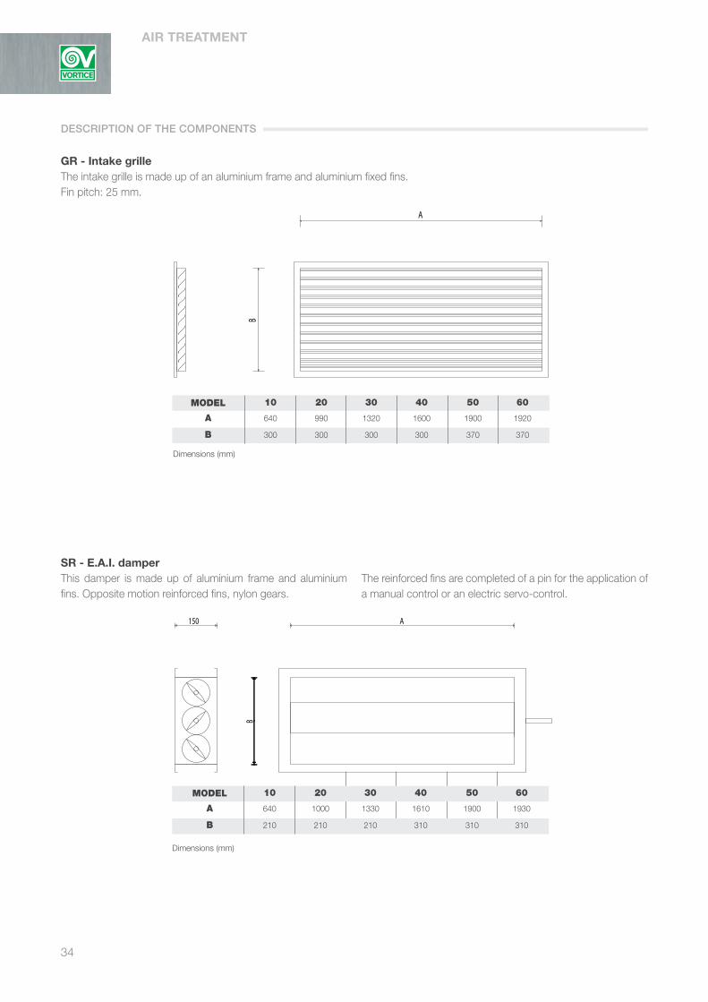
GR - Intake grilleThe intake grille is made up of an aluminium frame and aluminium fixed fins. Fin pitch: 25 mm.
MODEL 10 20 30 40 50 60
A 640 990 1320 1600 1900 1920
B 300 300 300 300 370 370
SR - E.A.I. damperThis damper is made up of aluminium frame and aluminium fins. Opposite motion reinforced fins, nylon gears.
The reinforced fins are completed of a pin for the application of a manual control or an electric servo-control.
DESCRIPTION OF THE COMPONENTS
Dimensions (mm)
MODEL 10 20 30 40 50 60
A 640 1000 1330 1610 1900 1930
B 210 210 210 310 310 310
Dimensions (mm)
35
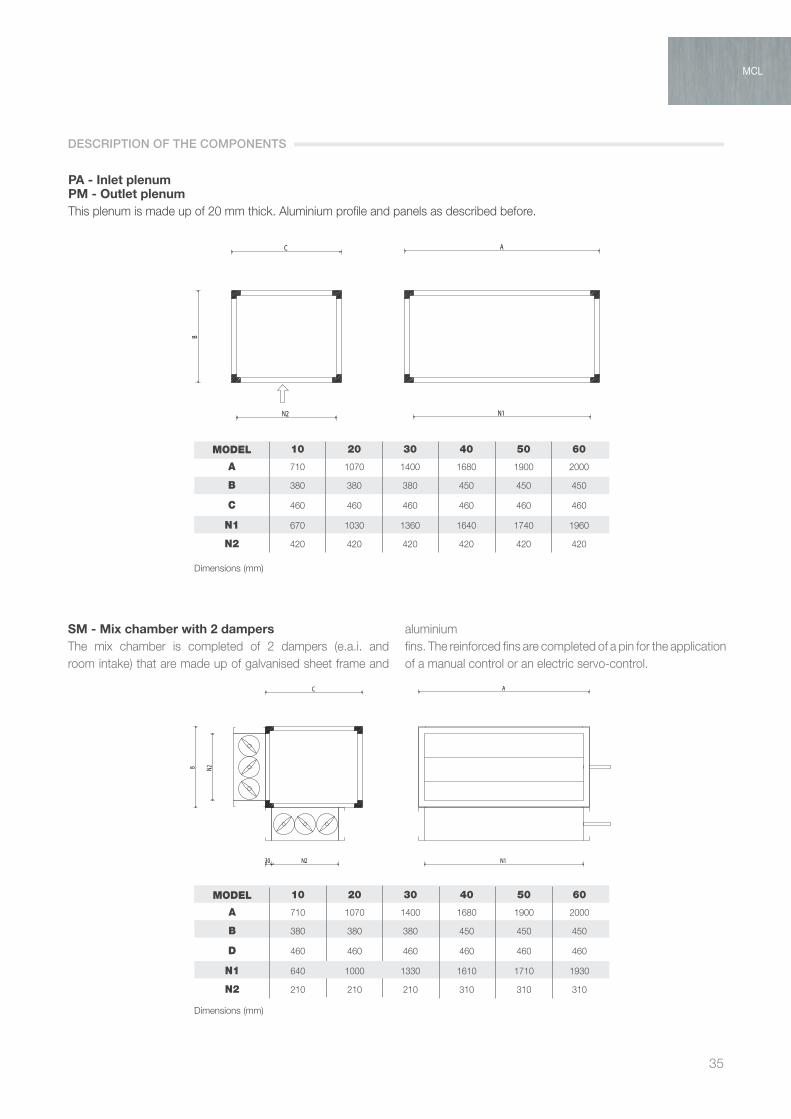
PA - Inlet plenumPM - Outlet plenumThis plenum is made up of 20 mm thick. Aluminium profile and panels as described before.
SM - Mix chamber with 2 dampersThe mix chamber is completed of 2 dampers (e.a.i. and room intake) that are made up of galvanised sheet frame and
aluminiumfins. The reinforced fins are completed of a pin for the application of a manual control or an electric servo-control.
DESCRIPTION OF THE COMPONENTS
MODEL 10 20 30 40 50 60
A 710 1070 1400 1680 1900 2000
B 380 380 380 450 450 450
C 460 460 460 460 460 460
N1 670 1030 1360 1640 1740 1960
N2 420 420 420 420 420 420
Dimensions (mm)
MCL
MODEL 10 20 30 40 50 60
A 710 1070 1400 1680 1900 2000
B 380 380 380 450 450 450
D 460 460 460 460 460 460
N1 640 1000 1330 1610 1710 1930
N2 210 210 210 310 310 310
Dimensions (mm)

AIR TREATMENT
36
SILR - Inlet silencerSILM - Outlet silencerThey are made up of an external shell with aluminium frame and 18 mm thick. Double panel. These silencers have in their internal side more than one 100 mm thick.
Sound absorbing baffles, which are made up of multiple layers of mineral fibres that are enclosed in a perforated galvanized steel sheet (L 700 mm).
MODEL 10 20 30 40 50 60
A 710 1070 1400 1680 1900 2000
B 380 380 380 450 450 450
C 900 900 900 960 960 960
N1 670 1030 1360 1640 1740 1960
N2 340 340 340 410 410 410
Acoustic attenuation
Frequency Hz
63 125 250 500 1000 2000 4000
Attenuation 5 9 16 30 39 39 31
DESCRIPTION OF THE COMPONENTS
Dimensions (mm)

37
VR - Inlet fanPlenum with inlet fan in a 18 mm thick. Double panel and fan as indicted in the basic unit.
MODEL 10 20 30 40 50 60
A 710 1070 1400 1680 1900 2000
B 380 380 380 450 450 450
C 460 460 460 460 460 460
N1 670 1030 1360 1640 1740 1960
N2 420 420 420 420 420 420
MODEL 10 20 30 40 50 60
Air flow - m3/h 1000 2000 2800 4000 4800 6000
Power at axle - W 370 740 740 1110 1110 1650
N. of fans - n. 1 2 2 2 3 3
Poles - n. 6 6 6 6 6 6
Max. sound pressure - dB(A) 69,3 69,3 70,3 69,1 69,1 69,1
Max. absorbed current - A 4,2 8,4 8,4 12 18 18
Engine speed variable variable variable variable variable variable
Protection grade - IP 54 54 54 54 54 54
Insulation class F F F F F F
Electric stoking - V/Ph/Hz 240/1/50 240/1/50 240/1/50 240/1/50 240/1/50 240/1/50
DESCRIPTION OF THE COMPONENTS
MCL
Dimensions (mm)

AIR TREATMENT
38
CM3 - Mix chamber with 3 dampersThis mix chamber is completed of n. 3 dampers (e.a.i. + by-pass + expulsion) which are made up of a galvanised sheet frame and aluminium fins. The opposite motion reinforced fins, nylon gears,
are completed of a pin for the application of a manual control or an electric servo-control.
MODEL 10 20 30 40 50 60
A 710 1070 1400 1680 1900 2000
B 380 380 380 450 450 450
C 900 900 900 960 960 960
N1 640 1000 1330 1610 1710 1930
N2 210 210 210 310 310 310
FT - Bag filterThis section has been realised as first filtering stage, with corrugated filtering cells which are made up of polyester fibre, class G4 (min. Eff. 90% ponderal), of a metal frame and of an
electro welded control net. The second filtering stage includes hard bags filters, high efficiency, class F7 (medium eff. EN779 60%) which are made up of glass microfibre paper and plastic frame.
MODEL 10 20 30 40 50 60
A 710 1070 1400 1680 1900 2000
B 380 380 380 450 450 450
C 500 500 500 500 500 500
N1 670 1030 1360 1640 1740 1960
N2 390 390 390 460 460 460
DESCRIPTION OF THE COMPONENTS
Dimensions (mm)
Dimensions (mm)

39
UP - Honeycombing pack humidifierHumidification with not-returnable water and evaporating pack which is made up of cellulose that is impregnated with 10 mm
thick. phenolic resins. This section is completed of a 2 folds PVC drops separator and a galvanized steel sheet collection tank.
UV - Steam humidificationThis section is prearranged for steam humidification; this predisposition consists of the supplying of a stainless steel distribution lance (Ø 30; suitable lenght) for each unit.
This section is completed of a 2 folds PVC drops separator and a galvanized steel sheet collection tank.
DESCRIPTION OF THE COMPONENTS
MCL
MODEL 10 20 30 40 50 60
A 710 1070 1400 1680 1900 2000
B 380 380 380 450 450 450
C 900 900 900 960 960 960
N1 670 1030 1360 1640 1740 1960
N2 340 340 340 410 410 410
Dimensions (mm)
Dimensions (mm)
MODEL 10 20 30 40 50 60
A 710 1070 1400 1680 1900 2000
B 380 380 380 450 450 450
C 900 900 900 960 960 960
N1 670 1030 1360 1640 1740 1960
N2 340 340 340 410 410 410

AIR TREATMENT
40
BE - Electric after-heating
MODEL 10 20 30 40 50 60
A 710 1070 1400 1680 1900 2000
B 380 380 380 450 450 450
C 450 450 450 450 450 450
N1 670 1030 1360 1640 1740 1960
N2 340 340 340 410 410 410
Coil dataThe electric coil are constructed with armoured resistances, with galvanised sheet frame, connection board and safety thermostat.
MODEL 10 20 30 40 50 60
Nominal power - kW 3,5 6,5 10 13 16,5 20
Phases 1 1 2 2 2 2
Elec. stoking - V/Ph/Hz 400/3/50 400/3/50 400/3/50 400/3/50 400/3/50 400/3/50
Leaving air temperature 25 25 25 25 25 25
It is calculated with entering air temperature = 15°C
DESCRIPTION OF THE COMPONENTS
Dimensions (mm)

41
BA - Water after-heating
Coil dataThe Copper - Aluminium extractable water heating coil is mechanically expanded. Its frame is made up of galvanised steel
sheet and its manifolds are made of steel with threaded connections. This coil is tested in water with dry air at a 30 Ate pressure.
MODEL 10 20 30 40 50 60
A 710 1070 1400 1680 1900 2000
B 380 380 380 450 450 450
C 450 450 450 450 450 450
N1 670 1030 1360 1640 1740 1960
N2 340 340 340 410 410 410
MODEL 10 20 30 40 50 60
Water flow - m3/h 1000 2000 2800 4000 4800 6000
Rows 2 2 2 2 2 2 2 2 2 2 2 2
In/out water temp. - °C 70/60 45/40 70/60 45/40 70/60 45/40 70/60 45/40 70/60 45/40 70/60 45/40
Entering air temp. = 15°C
Out air temp. °C 43,7 30,4 43,8 30,6 43,4 30,4 45,6 31,6 42,1 29,6 42,6 29,9
Water flow l/h 810 869 1602 1728 2586 2802 3674 3991 4107 4425 4799 5180
Power kW 9,4 5,04 18,6 10,0 30,0 16,3 42,6 23,1 47,6 25,7 55,7 30,0
DESCRIPTION OF THE COMPONENTS
MCL
Dimensions (mm)

AIR TREATMENT
42
PMV/PMF - Outlet plenum for flexible ductsIt is made up of a 20 mm thick aluminium frame and panel as indicated before.
The plenum is completed of galvanised sheet collars for the connection to flexible ducts Ø 200 mm.
MODEL 10 20 30 40 50 60
A 710 1070 1400 1680 1900 2000
B 380 380 380 450 450 450
C 450 450 450 450 450 450
N. of collars 2 3 3 4 5 6
Diametre 200 200 200 200 200 200
BM - Outlet small openingThe outlet small opening is composed of an aluminium frame and aluminium double row fins. Fin pitch: 25 mm
MODEL 10 20 30 40 50 60
A 640 990 1320 1600 1700 1920
B 300 300 300 300 370 370
DESCRIPTION OF THE COMPONENTS
Dimensions (mm)
Dimensions (mm)

43
MCL 10
PERFORMANCE CURVES A B C D E F (2) G (2) H (2)
Air flow rate m3/h 650 750 850 950 1000 1200 1400 1600
Static pressure (1) Pa 620 567 526 517 491 469 431 392
Signal to inverter Volt 0,28 1,4 1,9 2,5 3 3,6 4,2 4,8
Sound pressure level (2) dB(A) 69 69 70 69 69 70 69 69
LOAD DROP A B C D E F G H
Basic Unit 2R Pa 74 82 90 99 106 124 144 165
Basic Unit 4R Pa 89 100 113 126 134 164 195 228
Basic Unit 6R Pa 103 122 142 150 161 200 243 288
Basic Unit 2R+4R Pa 103 118 135 153 164 204 247 293
Basic Unit 2R+6R Pa 117 136 156 177 191 240 295 353
Basic Unit 4R+6R Pa 132 154 179 204 219 280 346 n.d.
GR Grid Pa 10 10 12 12 15 17 25 35
SR Damper Pa 10 10 12 12 15 17 25 35
SM Mixing box 2 dampers Pa 11 11 13 13 16 18 26 37
SILR/SILM Sound attenuator Pa 10 14 18 22 24 32 40 48
CM3 Mixing box 3 dampers Pa 12 12 14 14 17 20 29 40
FT Bag Filter Pa 20 30 35 40 45 55 65 75
UP Honeycomb pack humidifier Pa 14 14 21 28 35 47 60 82
UV Steam humidification Pa 4 4 6 8 10 12 15 27
BE Re-heating electric coil Pa 10 11 12 13 14 15 16 17
BA Re-heating water coil Pa 14 18 22 27 30 40 52 65
PMF Supply plenum Pa 10 10 11 11 11 12 13 14
BM Supply small opening Pa 11 11 13 13 16 18 26 37
MCL 20
PERFORMANCE CURVES A B C D E F (2) G (2) H (2)
Air flow rate m3/h 1300 1500 1700 1900 2000 2400 2800 3200
Static pressure (1) Pa 569 522 482 475 452 430 396 360
Signal to inverter Volt 0,28 1,4 1,9 2,5 3 3,6 4,2 4,8
Sound pressure level (2) dB(A) 69 69 70 69 69 70 69 69
LOAD DROP A B C D E F G H
Basic Unit 2R Pa 85 98 107 121 124 149 175 199
Basic Unit 4R Pa 122 144 162 184 192 236 284 330
Basic Unit 6R Pa 132 155 176 202 211 263 324 388
Basic Unit 2R+4R Pa 139 166 189 217 228 285 347 409
Basic Unit 2R+6R Pa 149 177 203 235 247 312 387 n.d.
Basic Unit 4R+6R Pa 186 223 258 298 315 399 n.d. n.d.
GR Grid Pa 10 12 15 20 20 30 40 50
SR Damper Pa 10 12 15 20 20 30 40 50
SM Mixing box 2 dampers Pa 11 13 16 21 21 32 42 53
SILR/SILM Sound attenuator Pa 12 16 20 24 26 34 42 52
CM3 Mixing box 3 dampers Pa 12 14 17 23 23 35 46 58
FT Bag Filter Pa 35 40 50 55 60 70 85 100
UP Honeycomb pack humidifier Pa 21 28 35 42 49 63 92 110
UV Steam humidification Pa 6 8 10 12 14 18 27 30
BE Re-heating electric coil Pa 12 14 15 15 16 17 18 20
BA Re-heating water coil Pa 17 22 27 33 36 49 63 79
PMF Supply plenum Pa 13 14 15 15 16 17 19 20
BM Supply small opening Pa 11 13 16 21 21 32 42 53
(1) The external static pressure will be determined subtracting to the total static pressure, the pressure drops of the various components;(2) Don’t use this airflow on units with cooling coil
DESCRIPTION OF THE COMPONENTS
MCL

AIR TREATMENT
44
MCL 30 PERFORMANCE CURVES A B C D E F G H (2)
Air flow rate m3/h 1300 1500 1700 1900 2000 2400 2800 3200
Static pressure (1) Pa 569 522 482 475 452 430 396 360
Signal to inverter Volt 0,28 1,4 1,9 2,5 3 3,6 4,2 4,8
Sound pressure level (2) dB(A) 69 69 70 69 69 70 70 69
LOAD DROP A B C D E F G H
Basic Unit 2R Pa 70 76 83 91 96 112 128 145
Basic Unit 4R Pa 91 103 115 129 138 166 195 225
Basic Unit 6R Pa 98 111 125 139 149 180 213 249
Basic Unit 2R+4R Pa 101 115 130 148 158 194 231 270
Basic Unit 2R+6R Pa 108 123 140 158 169 208 249 294
Basic Unit 4R+6R Pa 129 150 172 196 211 262 316 n.d.
GR Grid Pa 10 10 10 12 12 17 25 30
SR Damper Pa 10 10 10 12 12 17 25 30
SM Mixing box 2 dampers Pa 11 11 11 13 13 18 26 32
SILR/SILM Sound attenuator Pa 10 16 20 24 26 34 42 50
CM3 Mixing box 3 dampers Pa 12 12 12 14 14 20 29 35
FT Bag Filter Pa 20 30 35 40 45 55 65 75
UP Honeycomb pack humidifier Pa 14 21 28 35 42 55 71 102
UV Steam humidification Pa 4 6 8 10 12 15 21 27
BE Re-heating electric coil Pa 10 11 12 13 14 15 16 17
BA Re-heating water coil Pa 10 12 15 19 20 28 36 45
PMF Supply plenum Pa 10 10 10 11 11 12 13 14
BM Supply small opening Pa 11 11 11 13 13 18 26 32
MCL 40
PERFORMANCE CURVES A B C D E F (2) G (2) H (2)
Air flow rate m3/h 1600 2600 3200 3600 4200 4600 4900 5200
Static pressure (1) Pa 604 588 580 570 452 411 350 335
Signal to inverter Volt 0,28 1,4 1,9 2,5 3 3,6 4,2 4,8
Sound pressure level (2) dB(A) 67 67 68 68 69 70 69 72
LOAD DROP Aì B C D E F G H
Basic Unit 2R Pa 67 91 110 119 132 152 161 170
Basic Unit 4R Pa 81 122 153 169 191 224 239 254
Basic Unit 6R Pa 87 132 164 183 207 244 261 280
Basic Unit 2R+4R Pa 88 137 175 196 223 264 284 304
Basic Unit 2R+6R Pa 94 147 186 210 239 284 306 n.d.
Basic Unit 4R+6R Pa 108 178 229 260 298 356 n.d. n.d.
GR Grid Pa 10 10 12 15 15 20 20 25
SR Damper Pa 10 10 12 15 15 20 20 25
SM Mixing box 2 dampers Pa 11 11 13 16 16 21 21 26
SILR/SILM Sound attenuator Pa 10 12 20 24 28 34 38 42
CM3 Mixing box 3 dampers Pa 12 12 14 17 17 23 23 29
FT Bag Filter Pa 20 45 55 65 70 85 92 100
UP Honeycomb pack humidifier Pa 14 21 33 42 49 60 68 82
UV Steam humidification Pa 4 6 8 12 14 15 18 27
BE Re-heating electric coil Pa 10 14 15 16 17 18 19 19
BA Re-heating water coil Pa 7 15 22 27 32 40 45 50
PMF Supply plenum Pa 10 11 13 13 13 14 14 15
BM Supply small opening Pa 11 11 13 16 16 21 21 26
(1) The external static pressure will be determined subtracting to the total static pressure, the pressure drops of the various components (2) Don’t use this airflow on units with cooling coil
LOAD DROP
45
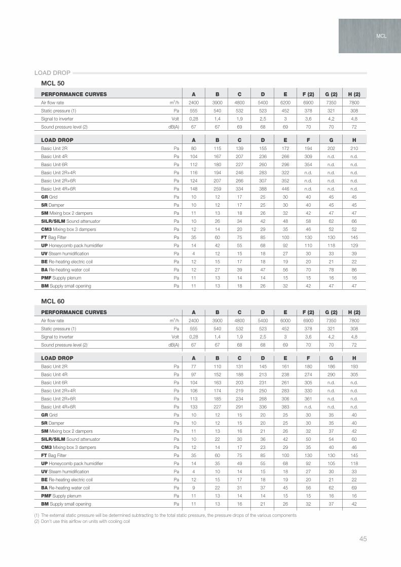
MCL 50
PERFORMANCE CURVES A B C D E F (2) G (2) H (2)
Air flow rate m3/h 2400 3900 4800 5400 6200 6900 7350 7800
Static pressure (1) Pa 555 540 532 523 452 378 321 308
Signal to inverter Volt 0,28 1,4 1,9 2,5 3 3,6 4,2 4,8
Sound pressure level (2) dB(A) 67 67 69 68 69 70 70 72
LOAD DROP A B C D E F G H
Basic Unit 2R Pa 80 115 139 155 172 194 202 210
Basic Unit 4R Pa 104 167 207 236 266 309 n.d. n.d.
Basic Unit 6R Pa 112 180 227 260 296 354 n.d. n.d.
Basic Unit 2R+4R Pa 116 194 246 283 322 n.d. n.d. n.d.
Basic Unit 2R+6R Pa 124 207 266 307 352 n.d. n.d. n.d.
Basic Unit 4R+6R Pa 148 259 334 388 446 n.d. n.d. n.d.
GR Grid Pa 10 12 17 25 30 40 45 45
SR Damper Pa 10 12 17 25 30 40 45 45
SM Mixing box 2 dampers Pa 11 13 18 26 32 42 47 47
SILR/SILM Sound attenuator Pa 10 26 34 42 48 58 62 66
CM3 Mixing box 3 dampers Pa 12 14 20 29 35 46 52 52
FT Bag Filter Pa 35 60 75 85 100 130 130 145
UP Honeycomb pack humidifier Pa 14 42 55 68 92 110 118 129
UV Steam humidification Pa 4 12 15 18 27 30 33 39
BE Re-heating electric coil Pa 12 15 17 18 19 20 21 22
BA Re-heating water coil Pa 12 27 39 47 56 70 78 86
PMF Supply plenum Pa 11 13 14 14 15 15 16 16
BM Supply small opening Pa 11 13 18 26 32 42 47 47
MCL 60
PERFORMANCE CURVES A B C D E F (2) G (2) H (2)
Air flow rate m3/h 2400 3900 4800 5400 6000 6900 7350 7800
Static pressure (1) Pa 555 540 532 523 452 378 321 308
Signal to inverter Volt 0,28 1,4 1,9 2,5 3 3,6 4,2 4,8
Sound pressure level (2) dB(A) 67 67 68 68 69 70 70 72
LOAD DROP A B C D E F G H
Basic Unit 2R Pa 77 110 131 145 161 180 186 193
Basic Unit 4R Pa 97 152 188 213 238 274 290 305
Basic Unit 6R Pa 104 163 203 231 261 305 n.d. n.d.
Basic Unit 2R+4R Pa 106 174 219 250 283 330 n.d. n.d.
Basic Unit 2R+6R Pa 113 185 234 268 306 361 n.d. n.d.
Basic Unit 4R+6R Pa 133 227 291 336 383 n.d. n.d. n.d.
GR Grid Pa 10 12 15 20 25 30 35 40
SR Damper Pa 10 12 15 20 25 30 35 40
SM Mixing box 2 dampers Pa 11 13 16 21 26 32 37 42
SILR/SILM Sound attenuator Pa 10 22 30 36 42 50 54 60
CM3 Mixing box 3 dampers Pa 12 14 17 23 29 35 40 46
FT Bag Filter Pa 35 60 75 85 100 130 130 145
UP Honeycomb pack humidifier Pa 14 35 49 55 68 92 105 118
UV Steam humidification Pa 4 10 14 15 18 27 30 33
BE Re-heating electric coil Pa 12 15 17 18 19 20 21 22
BA Re-heating water coil Pa 9 22 31 37 45 56 62 69
PMF Supply plenum Pa 11 13 14 14 15 15 16 16
BM Supply small opening Pa 11 13 16 21 26 32 37 42
(1) The external static pressure will be determined subtracting to the total static pressure, the pressure drops of the various components (2) Don’t use this airflow on units with cooling coil
MCL
LOAD DROP

AIR TREATMENT
46
Fan with directly coupled engine constant air flowThe electronic motor is equipped with inverter programmed to maintain a constant flow selectable between 8 preset values depending on the model.
Controls Standard Control through the signal +5 volts this on the
engine modulated through the potentiometer supplied as standard with which it is possible to select the range between the 8 available. At the request in the send order phase, possibility of
control through signal 0-10 Volts or 4-20 mA supplied by thermoregulation Score, with which manage the automatic flow between the 8 available.
Connection outline of control signal
Dip 1 = ON; Dip 2 = OFF; Dip 3 = OFF
Fig. 1
Dip 1 = OFF; Dip 2 = ON; Dip 3 = OFF
Fig. 2
Dip 1 = OFF; Dip 2 = OFF; Dip 3 = ON
Fig. 3
Electric connections schedule
ELECTRIC CONNECTIONS

47
CONTROL CONTROL STATE OF R6
SUPPLY V+ 10V max
MINIMUM Vmin 0 + 0.5 V+ CONNECT
REGULATOR IN Vmin + V+
MAXIMUM Vmax 0.5 V+ OPEN
REGULATOR IN 0 + Vmax
- IN and V+ are referred to V-- Impedance between IN and V- must be bigger than 50 Kohn
MCL
CONNECTION OUTLINE WITH POTENTIOMETER

AIR TREATMENT
48
T.S.P. [Pa]
Connections side:
Rows
Rows
Air volume [m3/h]
INDICATE CONFIGURATION:
SELECT COMPONENTS AND ACCESSORIES:
[BAC] Heating coil
[BAF] Cooling coil
[GR] Grid
[SR] Damper
[SM] Mixing box with 2 dampers
[SILR] Return sound attenuator
[SILM] Supply sound attenuator
[CM3] Mixing box with 3 dampers
[FT] Bag filter
[UP] Honeycomb pack humidifier
[UV] Steam humidification
[BE] Re-heating electric coil
[BA] Re-heating water coil
[PMF] Supply plenum
[BM] Supply small opening
[CM] Manual control for damper
EXTERNAL STATIC PRESSURE (*): Pa
TOTAL PRICE LIST: v
LF
Pressure drops [Pa]
Price List [v]
RH
YES NO
YES NO
YES NO
YES NO
YES NO
YES NO
YES NO
YES NO
YES NO
YES NO
YES NO
YES NO
YES NO
[n° pieces]
(*) The external static pressure is determined subtracting to the total static pressure, the pressure drops of the various components
MCL Quotation Table
SAMPLE UNIT SELECTION
49
MCL
NOTE

AIR TREATMENT
50
PRODUCT SPECIFICATIONS
STEEL CLEAN is designed to meet plant engineering demands of industrial or commercial sectors such as: - food industry - pharmaceutical industry - hospitals - electronic industry - clean rooms
VORTICE offers an extremely versatile product, which is also easy to sterilize. It is drew up for those spaces where cleanliness is required every day, and where air quality is a guarantee of protection for the customer. The internal chamber is made of high thickness stainless steel
AISI 304 sheet with rounded corners. Each section is completely TIG welded in order to ensure the absence of sharp edges. Thermal and noise insulation is warranted by an aluminium
structure with sandwich panels having thickness of 100 mm. The panels are shell shaped and contain expanded
polyurethane with density 40 kg/m3. Components are easy to access for cleaning and washing operations.
KEY FEATURES
STEEL CLEANSanitary units

51
Available sections1. Fresh air damper2. Mixing box with 2 or 3 dampers3. Return section4. Panel filters, soft-bag filters, rigid-bag filters, absolute filters
5. Heating, cooling and after-heating coils6. Electric coils7. Adiabatic or steam humidification8. Supply section
fig. 1 fig. 2
STEEL CLEAN
Baseframe realized in galvanized or stainless steel AISI 304/316 high thickness sheets suitably bended to assure rigidity and strenghtness to the unit.
Adjustable feet, made of stainless or galvanized steel, with a plastic support.
Internal chamber in stainless steel AISI 304, or on request AISI 316, with rounded corners. The lower part of the chamber functions as a drip tray, with great slopes and an appropriate outlet to allow condensation flow (fig. 1).
Internal guides, supports and locks are in stainless steel AISI 304, or on request AISI 316.
Sandwich paneling is 100 mm thick, external paneling is realized in: prepainted sheet, aluminium, stainless steel.
Centrifugal fan without scroll, flanged motor, including three cold wires. Motor rotor with bushing, support unit, motor support and solid base frame with adjustable modular construction. Centrifugal impeller with backward curved blades made from welded and painted steel sheet metal, secured to the shaft of a flanged motor, statically and dynamically balanced in accordance with DIN ISO 1940.
The fans can be fitted with a measuring device to determine flow-rate. Square connection fitting on the intake side, with elastic joint element. Performance (without actuator) included in accuracy class 1 in accordance with DIN 24166 (Fig. 2).
Filter sections are installed over stainless steel frames. The range includes prefilter G2 metallic or G4 synthetic, softbag filters, rigid-bag filters eff. F5/F6/F7/F9 and absolute filters H14 (fig. 3).
Coils made of: - Copper tube - Aluminium fins - Copper tube - Aluminium prepainted fins - Copper tube - Copper fins - Copper tube - Copper tinned fins - Stainless steel AISI 304 tube - Aluminium fins - Stainless steel AISI 304 tube - Aluminium prepainted fins - Stainless steel AISI 304 tube - Stainless steel AISI 304 fins - Stainless steel AISI 316 tube - Stainless steel AISI 304 fins
CONSTRUCTIONAL FEATURES

AIR TREATMENT
52
PRODUCT SPECIFICATIONS
The air handling units series HPU have been designed in order to satisfy all requirements coming from the plant enginnering for very special applications such as:
- food industry, - pharmaceutical laboratories - clean rooms and offer a high cleanliness level and a perfect washability.
These features are proper of those productive industries where air quality and absence of contaminants are the absolute priority as a warrant of the final product.
The special configuration of the structure made of glassfiber reinforced plastic, with internal rounded corners (coplanar and without junctions) and inspectionable in each section makes the optimum structure in order to meet a high cleanliness level which is necessary in order to prevent any bacterial proliferation. The whole bottom of the unit is supplied with stainless
steel drain pan. All the internal components are removable and easily
accessible for maintenance and cleaning operations.
KEY FEATURES
PRO-CLEANSanitary units for food industry
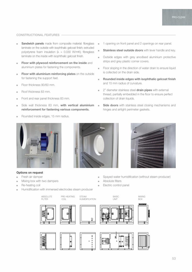
53
ABSOLUTE FILTER
PRE-HEATING COIL
STEAM HUMIDIFICATION
BASIC UNIT
MIXING BOX
PRO-CLEAN
Options on request Fresh air damper
Mixing box with two dampers Re-heating coil Humidification with immersed electrodes steam producer
Spayed water humidification (without steam producer) Absolute filters Electric control panel
Sandwich panels made from composite material: fibreglass laminate on the outside with isophthalic gelcoat finish; extruded polystyrene foam insulation (λ = 0.030 W/mK); fibreglass laminate on the inside with isophthalic gelcoat finish.
Floor with plywood reinforcement on the inside and aluminium plates for fastening the components.
Floor with aluminium reinforcing plates on the outside for fastening the support feet.
Floor thickness 90/60 mm.
Roof thickness 83 mm.
Front and rear panel thickness 83 mm.
Side wall thickness 83 mm, with vertical aluminium reinforcement for fastening various components.
Rounded inside edges, 15 mm radius.
1 opening on front panel and 2 openings on rear panel.
Stainless steel outside doors with lever handle and key.
Outside edges with grey anodised aluminium protective strips and grey plastic corner covers.
Floor sloping in the direction of water drain to ensure liquid is collected on the drain side.
Rounded inside edges with isophthalic gelcoat finish and 15 mm radius of curvature.
2” diameter stainless steel drain pipes with external thread, partially embedded in the floor to ensure perfect collection of drain liquids.
Side doors with stainless steel closing mechanisms and hinges and airtight perimeter gaskets.
CONSTRUCTIONAL FEATURES

AIR TREATMENT
54
TVLThermoventilating units horizontal and vertical execution
PRODUCT SPECIFICATIONS
The TVL fan coils can fulfil heating and cooling requirements in medium and large civil and industrial environments. This series uses double suction centrifugal fans with
forward curved blades and features 9 models with flow-rates from 1.700 m3/h to 25.000 m3/h, offering extremely simple installation and flexibility.
Coarse filtering by: corrugated filters with large surface area, class G4, synthetic filter media with weighted efficiency ≥ 90%, galvanised frame and retaining mesh.
Heat exchange coils: water-cooled, made from 5/8” copper tubes with continuous aluminium fins, 2.5 mm pitch. The tubes are mechanically expanded to ensure perfect coupling between tube and fin and consequently perfect heat exchange. The fins have a corrugated surface to ensure rigidity and create air turbulence, increasing the heat exchange coefficient. All coils can be removed both from the side with fittings and the opposite side. Electric coils: made using finned tubular air heaters with
one or more stages. Dimensioned as post-heating to a ∆t of 8°C. For other powers, contact the Sales Office. Fan assembly: the fan assembly is supported by a press
formed galvanised sheet metal base with special rubber vibration dampers. Double suction centrifugal fans with
forward curved blades can be installed. The impellers are statically and dynamically balanced in accordance with the relevant standards in force. The units use an individual sealed ball bearing ring with lifetime lubrication, rated for a minimum of 40,000 operating hours. The motors installed are three-phase asynchronous, with closed construction, fan cooled, squirrel cage rotor, compliant with IEC 60072-1, IEC 60034.
Frame made using a modular system of extruded anodised aluminium alloy section bars (in accordance with UNI 9006/1), joined by die-cast aluminium corners. Sandwich panels, insulated using polyurethane foam, density 40 kg/m3, 23 mm thick. Outside panel made from coated sheet metal, 6/10
thickness, inside panel made from galvanised sheet metal, 6/10 thickness. (variants such as 50 mm thick panelling or different materials such as: AISI 304 stainless steel, Peraluman... will be quoted on specific request by our technical-sales department).
KEY FEATURES

55
TVL 020
Portata aria / Air volume mc/h
1000
4000
6000
1000
0
2000
3000
5000
8000
TVL 030
TVL 040
TVL 060
TVL 080
1200
0
1400
0
1800
0
1600
0
2000
0
2200
0
2400
0
2600
0
2800
0
TVL 100
TVL 120
TVL 170
TVL 250
velocità sulla batteria
2.0 2.5 3.0 3.5
3000
0
Air volume mc/h
TVL
The TVL series units are selected according to: Air flow-rate
Type of system: 2- or 4-pipe (heating/cooling or both)
Vertical or horizontal configuration
The following tables help determine the most suitable model for the system in question.
The flow-rates are represented in the following diagram in m3/h, highlighting the velocity across the coil at 2 - 2.5 - 3.0 m/sec.
TVL SERIES
GR Intake grille with fixed aluminium finsSR Control damper with motor drive shaftPA Intake plenumSM Mixing chamber complete with 2 control dampers featuring motor drive shaft PM Outlet plenum complete with three outlets featuring two rows of adjustable aluminium bladesMS Safety micro-switch
VB Variable pitch pulleysCM Manual damper controlTPV Coated sheet metal rain cover for vertical unitsTPH Coated sheet metal rain cover for horizontal unitsXXX Additional soundproofing on fan compartmentPR Differential pressure switchMA Water column differential pressure gauge
TVL SERIES

AIR TREATMENT
56
MODEL TVL 20 30 40 60 80 100 120 170 250Nom. air flow rate (v=2,5 m/sec) m3/h 2200 2900 3600 5400 7600 9500 11300 14500 20800Static pressure Pa 600 600 600 600 600 600 600 600 600
FAN TVL 20 30 40 60 80 100 120 170 250Model fan AT 9/7 AT 9/9 AT 10/10 AT 12/12 AT 15/15 AT 18/18 ADH 450 ADH 500 ADH 630Max. motor power installed kW 1,1 1,1 1,5 2,2 3 4 5,5 7,5 11Poles n° 4 4 4 4 4 4 4 4 4Enclosure protection IP 55 55 55 55 55 55 55 55 55Insulation class F F F F F F F F FElectrical supply V / ph / Hz 230-400 / 3 / 50 400 / 3 / 50
FILTER TVL 20 30 40 60 80 100 120 170 250Efficiency G4 G4 G4 G4 G4 G4 G4 G4 G4Crossing speed m/s 2,55 2,40 1,74 2,07 1,93 2,02 2,08 2,21 2,31Average pressure drop Pa 80 80 80 80 80 80 80 80 80
2R hot water coil TVL 20 30 40 60 80 100 120 170 250Heating capacity (1) kW 18,59 24,68 31,33 45,56 63,97 76,94 93,35 114,76 173,54Supply air temperature °C 20,1 20,3 20,9 20,1 20 19,1 19,5 19,6 19,8Water flow dm3/h 1629 2163 2746 3994 5607 6744 6957 10510 15212Water pressure drop kPa 11,6 7,9 12,9 9,6 9,3 5,7 7,3 6 9,2Air pressure drop Pa 23,5 15,4 21,7 23,4 23,4 23,6 20,4 23,3 23,4Connection diameter Gas 3/4” 3/4” 3/4” 1” 1”1/4 1”1/2 1”1/2 2” 2”
3R hot water coil TVL 20 30 40 60 80 100 120 170 250Heating capacity (1) kW 26,21 34,39 43,8 64,5 90,46 108,56 131,63 169,05 244,7Supply air temperature °C 30,4 30,3 31,1 30,5 30,4 28,9 29,6 29,6 29,9Water flow dm3/h 1964 3023 3840 5654 7929 9516 11538 14818 21450Water pressure drop kPa 10,4 6,2 8,9 12 15,8 5 6,2 5,3 7,8Air pressure drop Pa 32,7 30,8 30,1 34,1 34,4 34,4 33,9 33,8 34,1Connection diameter Gas 3/4” 3/4” 1” 1”1/4 1”1/4 2” 2” 2”1/2 2”1/2
4R hot water coil TVL 20 30 40 60 80 100 120 170 250Heating capacity (1) kW 31,49 41,27 52,38 77,17 108,38 137,12 165,01 211,88 305,17Supply air temperature °C 37,5 37,3 38,2 37,5 37,4 37,9 38,4 38,4 38,6Water flow dm3/h 2760 3617 4592 6764 9500 12716 14465 18573 26750Water pressure drop kPa 9,2 5,1 7 9,5 9,7 16,3 24,8 19,5 35,5Air pressure drop Pa 44,2 42 41 46,5 46,9 54 46,3 46,1 46,6Connection diameter Gas 3/4” 1” 1” 1”1/4 1”1/2 1”1/2 1”1/2 2” 2”
4R cold water coil TVL 20 30 40 60 80 100 120 170 250Total cooling capacity (2) kW 12,77 17,11 22,15 31,43 41,03 53,61 65,98 84,51 123,26Supply air temperature °C 20 19,9 19,6 20 20,4 20,1 19,9 19,9 19,9Water flow dm3/h 2195 2940 3807 5402 7053 9213 11341 14525 21185Water pressure drop kPa 13,6 14,3 26,6 13,3 7,7 11,7 18,6 15 27,4Air pressure drop Pa 46,3 67,7 66 74,3 74,9 74,9 73,9 73,7 74,4Connection diameter Gas 3/4” 1” 1” 1”1/4 1”1/2 1”1/2 1”1/2 2” 2”
6R cold water coil TVL 20 30 40 60 80 100 120 170 250Total cooling capacity (2) kW 16,85 22,72 28 41,06 57,46 73,93 85,55 115,56 159,78Supply air temperature °C 17,2 17 17 17,3 17,3 17,8 17,3 16,9 17,6Water flow dm3/h 2896 3906 4813 7056 9875 12706 15481 19861 27461Water pressure drop kPa 16,5 20,5 10,8 14,7 14,9 26,4 13 35,5 19,3Air pressure drop Pa 58,4 84,3 82 92,5 93,2 106,7 92 91,8 92,6Connection diameter Gas 1” 1” 1”1/4 1”1/4 1”1/2 1”1/2 2” 2” 2”1/2
Electric coil TVL 20 30 40 60 80 100 120 170 250Electric capacity kW 6 7,5 9 15 20 25 30 38 55Electrical supply V / ph / Hz 400 / 3 / 50
TECHNICAL DATA
Electric coil: for sizing and quotations contact the Technical Department.(1) Inlet air Temp. -5°C, UR 90%, Water Temp. In/out 70/60°C. Air flow at 2,5 m/sec(2) Inlet air Temp. 32°C, UR 50%, Water Temp. in/out 7/12°C. Air flow at max speed. 2,5 m/sec

57
GR
SM2 Basic unit PM
40F
40
750
B
750
H1 H2 H3
H1/H2/H3
E
BE
500
R1
R2
R3
M1
M2
M3
V2
V3
EV1
Basic unit
EV1
/V2/
V3
GR SR
A
BE
500
Coil connections and access points
C
E E
PM
750
TVL 20-30-40-60-80-100 Front View
I
B
D
L
D
C
120-170-250
SM
500
120 A 120
LEFT SIDE
RIGHT SIDE
L
ATO
SX
RIG
HT
SID
E
Coil connections and drain
Access points
C
F
500
BE
500
PM
750
SM
C
TVL 20-30-40-60-80-100 Top View
1
A
L
C
120-170-250
E
M1
M2
M3
R1 R2
FH G
GH
HORIZONTAL UNIT (H)
TVL
POSSIBLE DIMENSIONS AND CONFIGURATION
GR
SM2 Basic unit PM
40F
40
750
B
750
H1 H2 H3
H1/H2/H3
E
BE
500
R1
R2
R3
M1
M2
M3
V2
V3
EV1
Basic unit
EV1
/V2/
V3
GR SR
A
BE
500
Coil connections and access points
C
E E
PM
750
TVL 20-30-40-60-80-100 Front View
I
B
D
L
D
C
120-170-250
SM
500
120 A 120
LEFT SIDE
RIGHT SIDE
L
ATO
SX
RIG
HT
SID
E
Coil connections and drain
Access points
C
F
500
BE
500
PM
750
SM
C
TVL 20-30-40-60-80-100 Top View
1
A
L
C
120-170-250
E
M1
M2
M3
R1 R2
FH G
GH
MODEL 20 30 40 60 80 100 120 170 250
H1 1290 1290 1290 1540 1540 1790 1790 2040 2290
H2 1540 1540 1540 1790 1790 2040 2040 2540 2790
H3 1540 1540 1540 1790 1790 2040 2040 2540 2790
B 600 600 650 790 1040 1040 1040 1290 1540
C 790 1040 1290 1290 1290 1540 1790 1790 2040
D 290 415 540 440 390 465 590 540 565
E 95 95 95 95 150 150 150 150 150
F 710 960 1210 1210 1210 1460 1710 1710 1960
G 210 210 210 410 510 610 610 710 910
H 210 310 310 510 710 710 710 910 1110
I 230 300 330 395 470 600 610 680 840
L 265 265 290 340 405 480 570 640 800
Dimensions (mm)

AIR TREATMENT
58
GR
SM2 Basic unit PM
40F
40
750
B
750
H1 H2 H3
H1/H2/H3
E
BE
500
R1
R2
R3
M1
M2
M3
V2
V3
EV1
Basic unit
EV1
/V2/
V3
GR SR
A
BE
500
Coil connections and access points
C
E E
PM
750
TVL 20-30-40-60-80-100 Front View
I
B
D
L
D
C
120-170-250
SM
500
120 A 120
LEFT SIDE
RIGHT SIDE
L
ATO
SX
RIG
HT
SID
E
Coil connections and drain
Access points
C
F
500
BE50
0
PM
750
SM
C
TVL 20-30-40-60-80-100 Top View
1
A
LC
120-170-250
E
M1
M2
M3
R1 R2
FH G
GH
MODEL 20 30 40 60 80 100 120 170 250 A 600 600 650 790 1040 1040 1040 1290 1540
V1 1290 1290 1290 1540 1540 1790 1790 2040 2290
V2 1540 1540 1540 1790 1790 2040 2040 2290 2540
V3 1790 1790 1790 2040 2040 2290 2290 2540 2790
C 790 1040 1290 1290 1290 1540 1790 1790 2040
E 95 95 95 95 150 150 150 150 150
F 710 960 1210 1210 1210 1460 1710 1710 1960
G 210 210 210 410 510 610 610 710 910
H 210 310 310 510 710 710 710 910 1110
I 230 300 330 395 470 600 610 680 840
L 265 265 290 340 405 480 570 640 800
POSSIBLE DIMENSIONS AND CONFIGURATION
VERTICAL UNIT (V)

59
TVL 20 heating
Coil performance in heating mode for each size of unit at different air flows and with different air and water inlet temperatures.
Air Water 70/60°C Water 45/40°C
Volume T. in T. out Power Water flow ∆p W T. out Power Water flow ∆p W m3/h °C °C kW dm3/h KPa °C kW dm3/h KPa
1700 -10 20,1 17,23 1510 10,1 11,2 12,11 2098 19,7
1700 -5 22,3 15,6 1368 9,1 14,1 10,94 1893 16,3
1700 0 26 14,89 1305 8,2 17 9,75 1688 13,1
1700 5 29 13,71 1202 7,4 20 8,56 1482 10,3
1700 10 31,9 12,53 1098 6,7 22,9 7,37 1275 8,3
1700 15 34,8 11,34 997 6 25,8 6,17 1068 6,7
Air Water 70/60°C Water 45/40°C
Volume T. in T. out Power Water flow ∆p W T. out Power Water flow ∆p W m3/h °C °C kW dm3/h KPa °C kW dm3/h KPa
2200 -10 16,9 19,94 1748 13,3 8,9 14,03 2429 26
2200 -5 20,1 18,59 1629 11,6 12,1 12,66 2192 21,4
2200 0 23,3 17,23 1510 10,1 15,2 11,26 1954 17,3
2200 5 26,4 15,86 1390 8,9 18,4 9,91 1715 13,5
2200 10 29,6 14,49 1270 8 21,5 8,52 1475 8,52
2200 15 32,7 13,1 1149 7 24,6 7,13 1234 8
Air Water 70/60°C Water 45/40°C
Volume T. in T. out Power Water flow ∆p W T. out Power Water flow ∆p W m3/h °C °C kW dm3/h KPa °C kW dm3/h KPa
2400 -10 15,9 20,92 1834 14,5 8,2 14,72 2549 28,5
2400 -5 19,1 19,5 1709 12,7 11,4 13,28 2300 23,5
2400 0 22,4 18,07 1584 11 14,7 11,84 2050 18,9
2400 5 25,6 16,64 1458 9,6 17,9 10,39 1799 14,8
2400 10 28,8 15,19 1332 8,4 21,1 8,93 1547 11,2
2400 15 32 13,74 1204 7,4 24,3 7,47 1294 8,5
Air Water 70/60°C Water 45/40°C
Volume T. in T. out Power Water flow ∆p W T. out Power Water flow ∆p W m3/h °C °C kW dm3/h KPa °C kW dm3/h KPa
2600 -10 14,9 21,85 1915 15,8 7,6 15,38 2662 30,9
2600 -5 18,3 20,36 1785 13,8 10,9 13,87 2402 25,5
2600 0 21,6 18,87 1654 12 14,1 12,37 2141 20,5
2600 5 24,8 17,37 1522 10,3 17,4 10,85 1878 16,1
2600 10 28,1 15,86 1390 8,9 20,7 9,33 1615 12,1
2600 15 31,4 14,34 1257 7,8 23,9 7,8 1350 9
RO
WS 2
RTVL
EFFICIENCY HEATING COILS

AIR TREATMENT
60
TVL 20 heating
Air Water 70/60°C Water 45/40°C
Volume T. in T. out Power Water flow ∆p W T. out Power Water flow ∆p W m3/h °C °C kW dm3/h KPa °C kW dm3/h KPa
1700 -10 32 24,03 2106 9,1 19,4 16,85 2918 17,3
1700 -5 34,1 22,4 1964 8,3 21,6 15,21 2634 14,3
1700 0 36,3 20,77 1820 7,5 23,7 13,57 2349 11,5
1700 5 38,4 19,13 1677 6,8 25,8 11,91 2063 9,2
1700 10 40,5 17,47 1532 6,2 27,9 10,26 1776 7,6
1700 15 42,6 15,82 1387 5,5 30 8,59 1488 6,2
Air Water 70/60°C Water 45/40°C
Volume T. in T. out Power Water flow ∆p W T. out Power Water flow ∆p W m3/h °C °C kW dm3/h KPa °C kW dm3/h KPa
2200 -10 28 28,12 2465 11,9 16,6 19,73 3416 23,2
2200 -5 30,4 26,21 2297 10,4 19,1 17,81 3084 19,1
2200 0 32,8 24,29 2129 9,3 21,4 15,88 2749 15,4
2200 5 35,2 22,36 1960 8,3 23,8 13,94 2413 12,1
2200 10 37,6 20,42 1790 7,4 26,2 11,99 2076 9,3
2200 15 40 18,48 1620 6,6 28,6 10,04 1738 7,4
Air Water 70/60°C Water 45/40°C
Volume T. in T. out Power Water flow ∆p W T. out Power Water flow ∆p W m3/h °C °C kW dm3/h KPa °C kW dm3/h KPa
2400 -10 26,6 29,59 2594 13,1 15,7 20,78 3957 25,6
2400 -5 29,1 27,58 2418 11,5 18,2 18,75 3247 21,1
2400 0 31,6 25,56 2241 10 20,7 16,72 2894 17
2400 5 34,1 23,53 2063 8,9 23,2 14,67 2540 13,3
2400 10 36,6 21,49 1884 7,9 25,6 12,62 2185 10
2400 15 39,1 19,45 1705 7 28,1 10,56 1829 7,9
Air Water 70/60°C Water 45/40°C
Volume T. in T. out Power Water flow ∆p W T. out Power Water flow ∆p W m3/h °C °C kW dm3/h KPa °C kW dm3/h KPa
2600 -10 25,4 31 2718 14,3 14,9 21,77 3769 27,9
2600 -5 28 28,89 2532 12,5 17,4 19,65 3402 23
2600 0 30,6 26,77 2347 10,9 20 17,51 3032 18,6
2600 5 33,2 24,64 2160 9,4 22,6 15,37 2661 14,5
2600 10 35,7 22,51 1973 8,4 25,1 13,22 2289 10,9
2600 15 38,3 20,36 1785 7,4 27,6 11,06 1919 8,4
RO
WS 3
R
EFFICIENCY HEATING COILS

61
Air Water 70/60°C Water 45/40°C
Volume T. in T. out Power Water flow ∆p W T. out Power Water flow ∆p W m3/h °C °C kW dm3/h KPa °C kW dm3/h KPa
1700 -10 40 28,61 2508 8,1 25 20,02 3467 14,6
1700 -5 41,6 26,68 2339 7,4 26,6 18,08 3130 12
1700 0 43,2 24,73 2168 6,8 28,2 16,12 2792 9,8
1700 5 44,8 22,78 1997 6,2 29,8 14,17 2454 8,2
1700 10 46,4 20,83 1826 5,6 31,3 12,21 2114 6,8
1700 15 48 18,86 1654 5,1 32,9 10,24 1773 5,6
Air Water 70/60°C Water 45/40°C
Volume T. in T. out Power Water flow ∆p W T. out Power Water flow ∆p W m3/h °C °C kW dm3/h KPa °C kW dm3/h KPa
2200 -10 35,6 33,78 2961 10,3 21,9 23,66 4097 19,9
2200 -5 37,5 31,49 2760 9,2 23,8 21,36 3697 16,4
2200 0 39,4 29,19 2558 8,3 25,7 19,04 3297 13,3
2200 5 41,3 26,88 2356 7,5 27,6 16,73 2896 10,4
2200 10 43,2 24,56 2153 6,7 29,4 14,4 2494 8,4
2200 15 45 22,24 1949 6 31,3 12,07 2090 6,8
Air Water 70/60°C Water 45/40°C
Volume T. in T. out Power Water flow ∆p W T. out Power Water flow ∆p W m3/h °C °C kW dm3/h KPa °C kW dm3/h KPa
2400 -10 34,1 35,66 3126 11,4 20,9 24,99 4326 22,1
2400 -5 36,1 33,24 2914 10 22,9 22,55 3904 18,2
2400 0 38,1 30,8 2700 8,9 24,9 20,11 3481 14,7
2400 5 40,1 28,36 2486 8 26,9 17,66 3057 11,5
2400 10 42,1 25,92 2272 7,2 28,8 15,2 2633 9
2400 15 44 23,45 2056 6,4 30,8 12,74 2205 7,2
Air Water 70/60°C Water 45/40°C
Volume T. in T. out Power Water flow ∆p W T. out Power Water flow ∆p W m3/h °C °C kW dm3/h KPa °C kW dm3/h KPa
2600 -10 32,8 37,46 3283 12,5 20 26,25 4546 24,3
2600 -5 34,9 34,9 3059 10,9 22,1 23,69 4101 20
2600 0 37 32,35 2835 9,6 24,1 21,12 3656 16,1
2600 5 39 29,78 2610 8,6 26,2 18,55 3211 12,6
2600 10 41,1 27,2 2385 7,6 28,2 15,96 2764 9,6
2600 15 43,1 24,62 2158 6,8 30,3 13,37 2315 7,6
RO
WS4R
TVL 20 heating
TVL
EFFICIENCY HEATING COILS
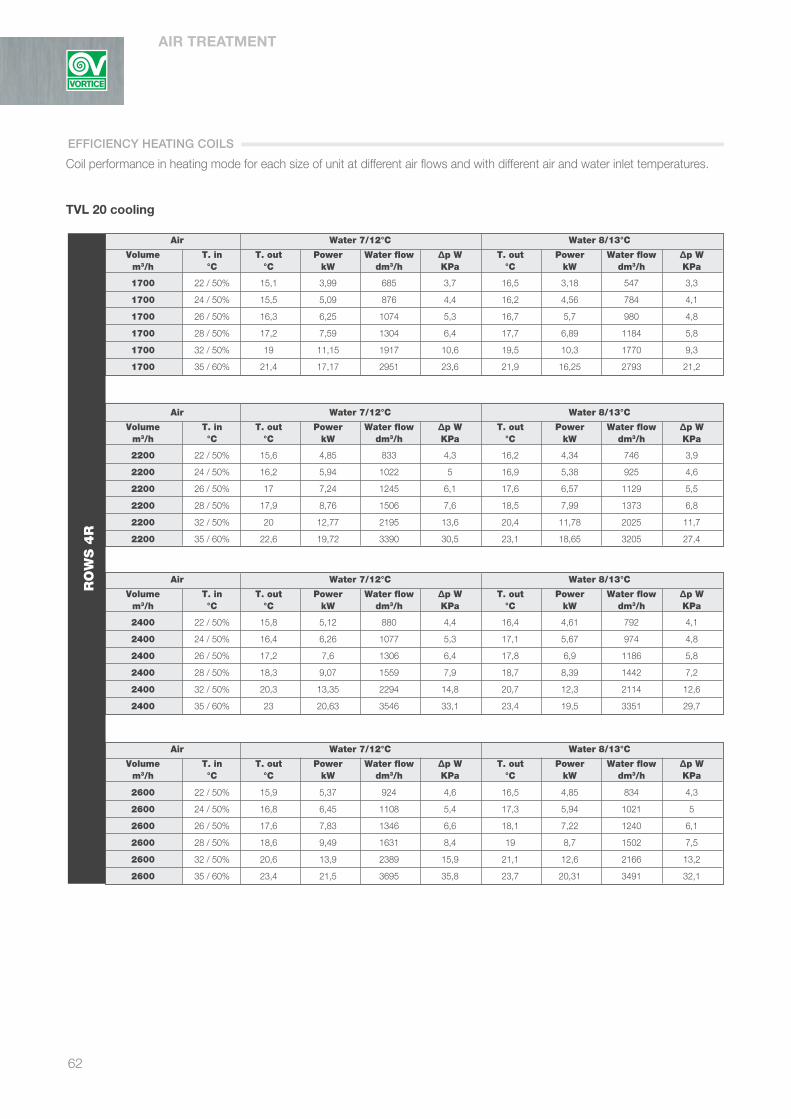
AIR TREATMENT
62
TVL 20 cooling
Coil performance in heating mode for each size of unit at different air flows and with different air and water inlet temperatures.
Air Water 7/12°C Water 8/13°C
Volume T. in T. out Power Water flow ∆p W T. out Power Water flow ∆p W m3/h °C °C kW dm3/h KPa °C kW dm3/h KPa
1700 22 / 50% 15,1 3,99 685 3,7 16,5 3,18 547 3,3
1700 24 / 50% 15,5 5,09 876 4,4 16,2 4,56 784 4,1
1700 26 / 50% 16,3 6,25 1074 5,3 16,7 5,7 980 4,8
1700 28 / 50% 17,2 7,59 1304 6,4 17,7 6,89 1184 5,8
1700 32 / 50% 19 11,15 1917 10,6 19,5 10,3 1770 9,3
1700 35 / 60% 21,4 17,17 2951 23,6 21,9 16,25 2793 21,2
Air Water 7/12°C Water 8/13°C
Volume T. in T. out Power Water flow ∆p W T. out Power Water flow ∆p W m3/h °C °C kW dm3/h KPa °C kW dm3/h KPa
2200 22 / 50% 15,6 4,85 833 4,3 16,2 4,34 746 3,9
2200 24 / 50% 16,2 5,94 1022 5 16,9 5,38 925 4,6
2200 26 / 50% 17 7,24 1245 6,1 17,6 6,57 1129 5,5
2200 28 / 50% 17,9 8,76 1506 7,6 18,5 7,99 1373 6,8
2200 32 / 50% 20 12,77 2195 13,6 20,4 11,78 2025 11,7
2200 35 / 60% 22,6 19,72 3390 30,5 23,1 18,65 3205 27,4
Air Water 7/12°C Water 8/13°C
Volume T. in T. out Power Water flow ∆p W T. out Power Water flow ∆p W m3/h °C °C kW dm3/h KPa °C kW dm3/h KPa
2400 22 / 50% 15,8 5,12 880 4,4 16,4 4,61 792 4,1
2400 24 / 50% 16,4 6,26 1077 5,3 17,1 5,67 974 4,8
2400 26 / 50% 17,2 7,6 1306 6,4 17,8 6,9 1186 5,8
2400 28 / 50% 18,3 9,07 1559 7,9 18,7 8,39 1442 7,2
2400 32 / 50% 20,3 13,35 2294 14,8 20,7 12,3 2114 12,6
2400 35 / 60% 23 20,63 3546 33,1 23,4 19,5 3351 29,7
Air Water 7/12°C Water 8/13°C
Volume T. in T. out Power Water flow ∆p W T. out Power Water flow ∆p W m3/h °C °C kW dm3/h KPa °C kW dm3/h KPa
2600 22 / 50% 15,9 5,37 924 4,6 16,5 4,85 834 4,3
2600 24 / 50% 16,8 6,45 1108 5,4 17,3 5,94 1021 5
2600 26 / 50% 17,6 7,83 1346 6,6 18,1 7,22 1240 6,1
2600 28 / 50% 18,6 9,49 1631 8,4 19 8,7 1502 7,5
2600 32 / 50% 20,6 13,9 2389 15,9 21,1 12,6 2166 13,2
2600 35 / 60% 23,4 21,5 3695 35,8 23,7 20,31 3491 32,1
RO
WS 4
R
EFFICIENCY HEATING COILS

63
Air Water 7/12°C Water 8/13°C Volume T. in T. out Power Water flow ∆p W T. out Power Water flow ∆p W m3/h °C °C kW dm3/h KPa °C kW dm3/h KPa
1700 22 / 50% 13,2 5,13 881 3,9 14,7 4,24 728 3,5
1700 24 / 50% 13,4 6,58 1132 4,7 14,1 5,91 1016 4,3
1700 26 / 50% 14 8,14 1399 5,8 14,7 7,37 1267 5,2
1700 28 / 50% 14,7 9,98 1715 7,2 15,4 9,08 1560 6,5
1700 32 / 50% 16,1 14,53 2498 12,6 16,7 13,48 2316 10,9
1700 35 / 60% 17,2 18,5 3180 19,6 18,8 21,02 3612 24,7
Air Water 7/12°C Water 8/13°C Volume T. in T. out Power Water flow ∆p W T. out Power Water flow ∆p W m3/h °C °C kW dm3/h KPa °C kW dm3/h KPa
2200 22 / 50% 13,6 6,31 1084 4,6 14,4 5,68 975 4,2
2200 24 / 50% 14,1 7,79 1338 5,5 14,8 7,06 1213 5
2200 26 / 50% 14,9 9,48 1629 6,8 15,4 8,64 1485 6,1
2200 28 / 50% 15,7 11,53 1982 8,6 16,2 10,54 1812 7,7
2200 32 / 50% 17,2 16,85 2896 16,5 17,8 15,6 2680 14,2
2200 35 / 60% 19,5 25,74 4425 36,2 20,1 24,41 4196 32,6
Air Water 7/12°C Water 8/13°C Volume T. in T. out Power Water flow ∆p W T. out Power Water flow ∆p W m3/h °C °C kW dm3/h KPa °C kW dm3/h KPa
2400 22 / 50% 13,8 6,69 1150 4,8 14,6 6,05 1040 4,4
2400 24 / 50% 14,4 8,21 1411 5,8 15 7,45 1281 5,3
2400 26 / 50% 15,1 9,98 1715 7,2 15,7 9,07 1560 6,5
2400 28 / 50% 15,9 12,12 2083 9,2 16,5 11,08 1904 8,2
2400 32 / 50% 17,6 17,68 3040 18 18,1 16,36 2812 15,6
2400 35 / 60% 20 27,04 4647 39,6 20,5 25,62 4404 35,7
Air Water 7/12°C Water 8/13°C Volume T. in T. out Power Water flow ∆p W T. out Power Water flow ∆p W m3/h °C °C kW dm3/h KPa °C kW dm3/h KPa
2600 22 / 50% 14,1 7,05 1212 5 14,8 6,39 1098 4,6
2600 24 / 50% 14,6 8,61 1476 6,1 15,3 7,83 1346 5,5
2600 26 / 50% 15,4 10,45 1795 7,6 16 9,52 1636 6,8
2600 28 / 50% 16,2 12,66 2176 9,8 16,8 11,52 1979 8,6
2600 32 / 50% 17,9 18,46 3173 19,5 18,5 16,93 2909 16,6
2600 35 / 60% 20,4 28,26 4857 43 20,9 26,79 4604 38,8
RO
WS 6
R
TVL 20 cooling
TVL
EFFICIENCY HEATING COILS

AIR TREATMENT
64
TVL 30 heating
Coil performance in heating mode for each size of unit at different air flows and with different air and water inlet temperatures.
Air Water 70/60°C Water 45/40°C Volume T. in T. out Power Water flow ∆p W T. out Power Water flow ∆p W m3/h °C °C kW dm3/h KPa °C kW dm3/h KPa
2300 -10 20 23,22 2035 7,3 11,1 16,33 2828 12,5
2300 -5 22,9 21,63 1896 6,7 14 14,75 2551 10,4
2300 0 25,9 20,05 1757 6,2 17 13,13 2274 8,8
2300 5 28,8 18,45 1617 5,7 19,9 11,52 1994 7,4
2300 10 31,8 16,84 477 5,2 22,8 9,9 1714 6,2
2300 15 34,7 15,23 1335 4,7 25,7 8,27 1433 5,2
Air Water 70/60°C Water 45/40°C Volume T. in T. out Power Water flow ∆p W T. out Power Water flow ∆p W m3/h °C °C kW dm3/h KPa °C kW dm3/h KPa
2900 -10 17,1 26,48 2321 8,6 9,1 18,64 3228 16
2900 -5 20,3 24,68 2163 7,9 12,2 16,82 2912 13,2
2900 0 23,4 22,86 2004 7,2 15,3 14,98 2594 10,7
2900 5 26,5 21,03 1844 6,5 18,5 13,14 2274 8,8
2900 10 29,7 19,2 1683 5,9 21,6 11,28 1954 7,3
2900 15 32,8 17,35 1521 5,3 24,7 9,43 1632 5,9
Air Water 70/60°C Water 45/40°C Volume T. in T. out Power Water flow ∆p W T. out Power Water flow ∆p W m3/h °C °C kW dm3/h KPa °C kW dm3/h KPa
3200 -10 15,9 27,96 2451 9,2 8,3 19,69 3409 17,7
3200 -5 19,2 26,05 2284 8,4 11,5 17,76 3074 14,6
3200 0 22,4 24,13 2115 7,6 14,7 15,82 2738 11,8
3200 5 25,6 22,2 1946 6,9 17,9 13,87 2401 9,4
3200 10 28,8 20,26 1776 6,2 21,1 11,91 2062 7,7
3200 15 32 18,31 1605 5,6 24,2 9,95 1722 6,3
Air Water 70/60°C Water 45/40°C Volume T. in T. out Power Water flow ∆p W T. out Power Water flow ∆p W m3/h °C °C kW dm3/h KPa °C kW dm3/h KPa
3500 -10 14,9 29,35 2573 9,9 7,5 20,67 2579 19,4
3500 -5 18,2 27,35 2397 9 10,8 18,64 3228 16
3500 0 21,5 25,33 2220 8,1 14,1 16,6 2875 12,9
3500 5 24,8 23,3 2043 7,3 17,4 14,56 2520 10,1
3500 10 28 21,26 1864 6,6 20,6 12,5 2164 8,2
3500 15 31,3 19,21 1684 5,9 23,9 10,44 1807 6,6
RO
WS 2
R
EFFICIENCY HEATING COILS

65
TVL 30 heating
Air Water 70/60°C Water 45/40°C
Volume T. in T. out Power Water flow ∆p W T. out Power Water flow ∆p W m3/h °C °C kW dm3/h KPa °C kW dm3/h KPa
2300 -10 31,5 32,16 2819 5,7 19,2 22,58 3909 8,8
2300 -5 33,7 29,95 2626 5,3 21,3 2037 3526 7,7
2300 0 35,8 27,74 2432 5 23,4 18,14 3140 6,7
2300 5 38 25,52 2237 4,6 25,5 15,9 2753 5,8
2300 10 40,1 23,29 2041 4,3 27,6 13,66 2366 5
2300 15 42,2 21,05 1846 4 29,7 11,41 1976 4,3
Air Water 70/60°C Water 45/40°C Volume T. in T. out Power Water flow ∆p W T. out Power Water flow ∆p W m3/h °C °C kW dm3/h KPa °C kW dm3/h KPa
2900 -10 27,9 3703 3246 6,7 16,6 26,03 4506 11
2900 -5 30,3 34,39 3023 6,2 19 23,47 4063 9,3
2900 0 32,7 31,93 2799 5,7 21,4 20,89 3617 7,9
2900 5 35,1 29,37 2574 5,2 23,8 18,31 3170 6,8
2900 10 37,4 26,79 2348 4,8 26,1 15,72 2722 5,7
2900 15 39,8 24,21 2122 4,4 28,4 13,12 2272 4,8
Air Water 70/60°C Water 45/40°C Volume T. in T. out Power Water flow ∆p W T. out Power Water flow ∆p W m3/h °C °C kW dm3/h KPa °C kW dm3/h KPa
3200 -10 26,4 39,25 3441 7,2 15,6 27,59 4777 12,2
3200 -5 28,9 36,55 3204 6,6 18,1 24,88 4307 10,1
3200 0 31,4 33,84 2966 6,1 20,6 22,15 3834 8,6
3200 5 33,9 31,11 2727 5,5 23 19,41 3360 7,3
3200 10 36,4 28,38 2488 5,1 25,5 16,66 2884 6,1
3200 15 38,8 25,64 2247 4,6 27,9 13,9 2407 5,1
Air Water 70/60°C Water 45/40°C Volume T. in T. out Power Water flow ∆p W T. out Power Water flow ∆p W m3/h °C °C kW dm3/h KPa °C kW dm3/h KPa
3500 -10 25,1 41,35 3624 7,7 14,7 29,07 5033 13,5
3500 -5 27,7 38,5 3375 7 17,2 26,26 4538 11,1
3500 0 30,3 35,64 3124 6,4 19,8 23,33 4039 9,2
3500 5 32,8 32,77 2872 5,9 22,4 20,44 2539 7,7
3500 10 35,4 29,88 2619 5,3 24,9 17,54 3037 6,4
3500 15 37,9 26,99 2366 4,8 27,4 14,63 2534 5,3
RO
WS 3
RTVL
EFFICIENCY HEATING COILS

AIR TREATMENT
66
TVL 30 heating
Air Water 70/60°C Water 45/40°C
Volume T. in T. out Power Water flow ∆p W T. out Power Water flow ∆p W m3/h °C °C kW dm3/h KPa °C kW dm3/h KPa
2300 -10 39,3 38,18 3346 4,8 24,6 26,76 4633 6,8
2300 -5 40,9 35,56 3117 4,5 26,2 24,13 4177 6,1
2300 0 42,5 32,93 2886 4,2 27,8 21,49 3720 5,4
2300 5 44,1 30,3 2656 4 29,4 18,85 3264 4,8
2300 10 45,7 27,65 2424 3,8 30,9 16,2 2805 4,2
2300 15 47,3 25 2192 3,6 32,5 13,54 2345 3,8
Air Water 70/60°C Water 45/40°C
Volume T. in T. out Power Water flow ∆p W T. out Power Water flow ∆p W m3/h °C °C kW dm3/h KPa °C kW dm3/h KPa
2900 -10 35,4 44,31 3884 5,5 21,8 31,09 5383 8,2
2900 -5 37,3 41,27 3617 5,1 23,7 28,02 4852 7,2
2900 0 39,1 38,2 3349 4,8 25,6 24,95 4319 6,3
2900 5 41 35,14 3080 4,4 27,4 21,8 3788 5,5
2900 10 42,8 32,06 2810 4,2 29,2 18,79 3253 4,8
2900 15 44,7 28,97 2539 3,9 31,1 15,69 2717 4,2
Air Water 70/60°C Water 45/40°C Volume T. in T. out Power Water flow ∆p W T. out Power Water flow ∆p W m3/h °C °C kW dm3/h KPa °C kW dm3/h KPa
3200 -10 33,7 47,12 4130 5,8 20,7 33,07 5726 8,9
3200 -5 35,7 43,87 3845 5,4 22,7 29,81 5161 7,8
3200 0 37,7 40,61 3560 5 24,6 26,53 4593 6,8
3200 5 39,7 37,34 3273 4,7 26,6 23,26 4027 5,9
3200 10 41,6 34,07 2986 4,3 28,5 19,97 3458 5
3200 15 43,6 30,78 2698 4 30,5 16,67 2886 4,3
Air Water 70/60°C Water 45/40°C Volume T. in T. out Power Water flow ∆p W T. out Power Water flow ∆p W m3/h °C °C kW dm3/h KPa °C kW dm3/h KPa
3500 -10 32,2 49,77 4363 6,2 19,7 34,95 6051 9,6
3500 -5 34,3 46,34 4062 5,7 21,7 31,49 5453 8,4
3500 0 36,4 42,9 3760 5,3 23,8 28,03 4853 7,2
3500 5 38,5 39,43 3457 4,9 25,9 24,57 4254 6,2
3500 10 40,5 35,97 3153 4,5 27,9 21,09 3651 5,3
3500 15 42,6 32,49 2848 4,2 29,9 17,6 3047 4,5
RO
WS 4
R
EFFICIENCY HEATING COILS

67
TVL 30 cooling
Coil performance in cooling mode for each size of unit at different air flows and with different air and water inlet temperatures.
Air Water 7/12°C Water 8/13°C Volume T. in T. out Power Water flow ∆p W T. out Power Water flow ∆p W m3/h °C °C kW dm3/h KPa °C kW dm3/h KPa
2300 22 / 50% 15,1 5,41 930 3,9 16,2 4,21 723 3,4
2300 24 / 50% 15,4 6,92 1189 4,6 16,6 6,18 1061 4,2
2300 26 / 50% 16,2 8,47 1456 5,5 16,7 7,74 1331 5
2300 28 / 50% 17,1 10,3 1771 6,8 17,7 9,35 1607 6
2300 32 / 50% 19 15,13 2601 11,4 19,5 2403 2403 9,8
2300 35 / 60% 21,4 23,3 4005 25,3 21,9 22,07 3793 22,8
Air Water 7/12°C Water 8/13°C Volume T. in T. out Power Water flow ∆p W T. out Power Water flow ∆p W m3/h °C °C kW dm3/h KPa °C kW dm3/h KPa
2900 22 / 50% 15,5 6,47 1112 4,3 16,2 5,78 997 4
2900 24 / 50% 16,1 7,94 1365 5,2 16,8 7,19 1235 4,7
2900 26 / 50% 16,9 9,69 1665 6,3 17,5 8,78 1510 5,7
2900 28 / 50% 18,4 11,08 1904 7,8 18,4 10,69 1838 7
2900 32 / 50% 19,9 17,11 2940 14,3 20,3 15,79 2714 12,3
2900 35 / 60% 22,5 26,4 4537 31,8 22,9 24,97 4291 28,6
Air Water 7/12°C Water 8/13°C Volume T. in T. out Power Water flow ∆p W T. out Power Water flow ∆p W m3/h °C °C kW dm3/h KPa °C kW dm3/h KPa
3200 22 / 50% 15,7 6,88 1183 4,6 16,3 6,19 1064 4,2
3200 24 / 50% 16,3 8,43 1450 5,5 17 7,63 1311 5
3200 26 / 50% 17,2 10,24 1761 6,7 17,8 9,29 1596 6
3200 28 / 50% 18,3 12,2 2098 8,3 18,7 11,28 1939 7,5
3200 32 / 50% 20,2 17,99 3092 15,7 20,6 16,59 2851 13,5
3200 35 / 60% 22,9 27,79 4766 35 23,3 26,28 4517 31,4
Air Water 7/12°C Water 8/13°C Volume T. in T. out Power Water flow ∆p W T. out Power Water flow ∆p W m3/h °C °C kW dm3/h KPa °C kW dm3/h KPa
3500 22 / 50% 15,9 7,27 1250 4,8 16,5 6,57 1128 4,4
3500 24 / 50% 16,7 8,73 1500 5,7 17,3 8,04 1382 5,2
3500 26 / 50% 17,6 10,59 1821 7 18 9,77 1679 6,3
3500 28 / 50% 18,5 12,84 2206 8,8 18,9 11,82 2032 7,9
3500 32 / 50% 20,5 18,83 3236 17,1 21,1 17,07 2934 14,2
3500 35 / 50% 23,3 29,11 5003 38,1 23,7 27,5 4727 34,1
RO
WS 4
RTVL
EFFICIENCY COOLING COILS
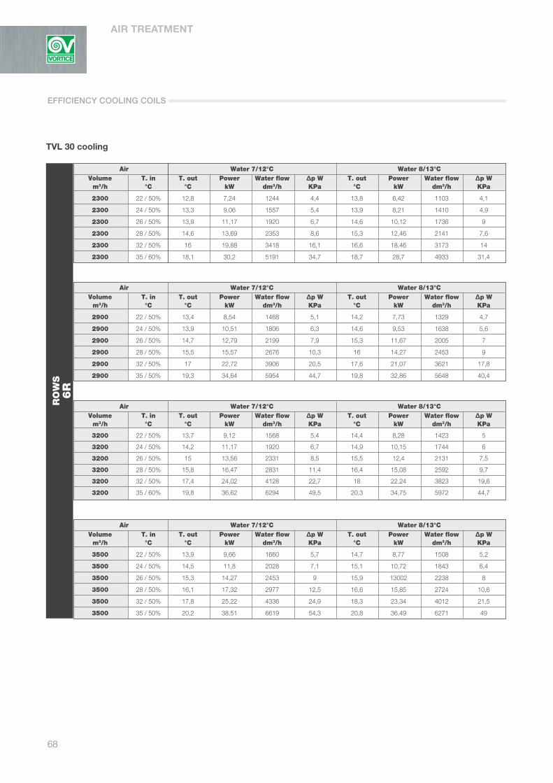
AIR TREATMENT
68
TVL 30 cooling
Air Water 7/12°C Water 8/13°C Volume T. in T. out Power Water flow ∆p W T. out Power Water flow ∆p W m3/h °C °C kW dm3/h KPa °C kW dm3/h KPa
2300 22 / 50% 12,8 7,24 1244 4,4 13,8 6,42 1103 4,1
2300 24 / 50% 13,3 9,06 1557 5,4 13,9 8,21 1410 4,9
2300 26 / 50% 13,9 11,17 1920 6,7 14,6 10,12 1736 9
2300 28 / 50% 14,6 13,69 2353 8,6 15,3 12,46 2141 7,6
2300 32 / 50% 16 19,88 3418 16,1 16,6 18,46 3173 14
2300 35 / 60% 18,1 30,2 5191 34,7 18,7 28,7 4933 31,4
Air Water 7/12°C Water 8/13°C Volume T. in T. out Power Water flow ∆p W T. out Power Water flow ∆p W m3/h °C °C kW dm3/h KPa °C kW dm3/h KPa
2900 22 / 50% 13,4 8,54 1468 5,1 14,2 7,73 1329 4,7
2900 24 / 50% 13,9 10,51 1806 6,3 14,6 9,53 1638 5,6
2900 26 / 50% 14,7 12,79 2199 7,9 15,3 11,67 2005 7
2900 28 / 50% 15,5 15,57 2676 10,3 16 14,27 2453 9
2900 32 / 50% 17 22,72 3906 20,5 17,6 21,07 3621 17,8
2900 35 / 50% 19,3 34,64 5954 44,7 19,8 32,86 5648 40,4
Air Water 7/12°C Water 8/13°C Volume T. in T. out Power Water flow ∆p W T. out Power Water flow ∆p W m3/h °C °C kW dm3/h KPa °C kW dm3/h KPa
3200 22 / 50% 13,7 9,12 1568 5,4 14,4 8,28 1423 5
3200 24 / 50% 14,2 11,17 1920 6,7 14,9 10,15 1744 6
3200 26 / 50% 15 13,56 2331 8,5 15,5 12,4 2131 7,5
3200 28 / 50% 15,8 16,47 2831 11,4 16,4 15,08 2592 9,7
3200 32 / 50% 17,4 24,02 4128 22,7 18 22,24 3823 19,6
3200 35 / 60% 19,8 36,62 6294 49,5 20,3 34,75 5972 44,7
Air Water 7/12°C Water 8/13°C Volume T. in T. out Power Water flow ∆p W T. out Power Water flow ∆p W m3/h °C °C kW dm3/h KPa °C kW dm3/h KPa
3500 22 / 50% 13,9 9,66 1660 5,7 14,7 8,77 1508 5,2
3500 24 / 50% 14,5 11,8 2028 7,1 15,1 10,72 1843 6,4
3500 26 / 50% 15,3 14,27 2453 9 15,9 13002 2238 8
3500 28 / 50% 16,1 17,32 2977 12,5 16,6 15,85 2724 10,6
3500 32 / 50% 17,8 25,22 4336 24,9 18,3 23,34 4012 21,5
3500 35 / 50% 20,2 38,51 6619 54,3 20,8 36,49 6271 49
RO
WS
6R
EFFICIENCY COOLING COILS

69
TVL
TVL 40 heating
Air Water 70/60°C Water 45/40°C Volume T. in T. out Power Water flow ∆p W T. out Power Water flow ∆p W m3/h °C °C kW dm3/h KPa °C kW dm3/h KPa
2900 -10 20,4 29,7 2603 11,7 11,4 20,87 3613 22,8
2900 -5 23,4 27,7 2428 10,3 14,3 18,85 3263 18,9
2900 0 26,3 25,68 2251 9,2 17,2 16,81 2911 15,3
2900 5 29,2 23,66 2074 8,2 20,1 14,77 2557 12,1
2900 10 32,1 21,63 1896 7,4 23 12,72 2202 9,4
2900 15 35,1 19,58 1717 6,6 25,9 10,66 1846 7,5
Air Water 70/60°C Water 45/40°C Volume T. in T. out Power Water flow ∆p W T. out Power Water flow ∆p W m3/h °C °C kW dm3/h KPa °C kW dm3/h KPa
3600 -10 17,7 33,6 2945 14,7 9,5 23,62 4089 28,7
3600 -5 20,9 31,33 2746 12,9 12,6 21,33 3693 23,8
3600 0 24 29,05 2547 11,2 15,7 19,02 3294 19,3
3600 5 27,1 26,76 2346 9,7 18,8 16,71 2893 15,
3600 10 30,2 24,45 2143 8,6 21,9 14,38 2490 11,5
3600 15 33,3 22,14 1941 7,6 24,9 12,05 2086 8,7
Air Water 70/60°C Water 45/40°C Volume T. in T. out Power Water flow ∆p W T. out Power Water flow ∆p W m3/h °C °C kW dm3/h KPa °C kW dm3/h KPa
4000 -10 1,4 35,62 3122 16,4 7,5 23,58 4083 30
4000 -5 19,7 33,21 2911 14,4 11,8 22,62 3915 26,5
4000 0 22,9 30,8 2699 12,5 15 20,17 3492 21,4
4000 5 26,1 28,36 2486 10,7 18,1 17,71 3067 16,9
4000 10 29,3 25,92 2272 9,3 21,3 15,25 2640 12,8
4000 15 32,4 23,46 2056 8,2 24,5 12,77 2211 9,4
Air Water 70/60°C Water 45/40°C Volume T. in T. out Power Water flow ∆p W T. out Power Water flow ∆p W m3/h °C °C kW dm3/h KPa °C kW dm3/h KPa
4300 -10 15,6 37,06 3248 17,6 6,7 24,22 4194 32
4300 -5 18,9 34,55 3028 15,4 11,3 23,53 4073 28,5
4300 0 22,1 32,03 2807 13,4 14,5 20,98 3633 23,1
4300 5 25,4 29,5 2586 11,5 17,7 18,43 3190 18,2
4300 10 28,6 26,95 2363 9,8 20,9 15,86 2745 13,8
4300 15 31,9 24,39 2138 8,6 24,2 13,28 2299 9,9
RO
WS
2R
TVL
Coil performance in heating mode for each size of unit at different air flows and with different air and water inlet temperatures.
EFFICIENCY HEATING COILS

AIR TREATMENT
70
TVL 40 heating
Air Water 70/60°C Water 45/40°C Volume T. in T. out Power Water flow ∆p W T. out Power Water flow ∆p W m3/h °C °C kW dm3/h KPa °C kW dm3/h KPa
2900 -10 32,2 41,16 3608 8,2 19,6 28,86 4997 14,9
2900 -5 34,3 38,37 3363 7,5 21,7 26,06 4512 12,3
2900 0 36,4 35,57 3118 6,9 23,8 23,24 4023 10
2900 5 38,6 32,76 2872 6,3 25,9 20,41 3534 8,4
2900 10 40,7 29,93 2624 5,7 28 17,57 3042 7
2900 15 42,8 27,1 2375 5,2 30,1 14,72 2549 5,7
Air Water 70/60°C Water 45/40°C Volume T. in T. out Power Water flow ∆p W T. out Power Water flow ∆p W m3/h °C °C kW dm3/h KPa °C kW dm3/h KPa
3600 -10 28,8 47 4119 9,8 17,2 32,97 5708 19,1
3600 -5 31,1 43,8 3840 8,9 19,6 29,76 5153 15,8
3600 0 33,5 40,6 3559 8,1 21,9 26,54 4594 12,8
3600 5 35,8 37,88 3276 7,3 24,2 23,3 4034 10
3600 10 38,2 34,14 2993 6,6 26,5 20,05 3471 8,2
3600 15 40,5 30,9 2708 5,9 28,9 16,79 2906 6,6
Air Water 70/60°C Water 45/40°C Volume T. in T. out Power Water flow ∆p W T. out Power Water flow ∆p W m3/h °C °C kW dm3/h KPa °C kW dm3/h KPa
4000 -10 27,1 50,03 4385 11 16,1 35,11 6079 21,5
4000 -5 29,6 46,63 4087 9,7 18,5 31,7 5488 17,8
4000 0 32,1 43,21 3788 8,8 21 28,25 4892 14,3
4000 5 34,5 39,78 3487 7,9 23,4 24,8 4294 11,3
4000 10 37 36,33 3185 7 25,9 21,34 3695 8,9
4000 15 39,4 32,87 2882 6,3 28,3 17,86 3092 7,1
Air Water 70/60°C Water 45/40°C Volume T. in T. out Power Water flow ∆p W T. out Power Water flow ∆p W m3/h °C °C kW dm3/h KPa °C kW dm3/h KPa
4300 -10 26 52,18 4754 11,9 15,3 36,64 6343 23,3
4300 -5 28,6 48,64 4263 10,4 17,8 33,07 5726 19,2
4300 0 31,1 45,08 3951 9,3 20,4 29,48 5104 15,5
4300 5 33,7 41,5 3637 8,3 22,9 25,87 4479 12,
4300 10 36,2 37,89 3322 7,4 25,4 22,25 3853 9,4
4300 15 38,7 24,28 3005 6,6 27,9 18,63 3225 7,5
RO
WS
3R
EFFICIENCY HEATING COILS

71
TVL
TVL 40 heating
Air Water 70/60°C Water 45/40°C Volume T. in T. out Power Water flow ∆p W T. out Power Water flow ∆p W m3/h °C °C kW dm3/h KPa °C kW dm3/h KPa
2900 -10 40 48,86 4283 6,5 25 34,2 5922 10,3
2900 -5 41,6 45,54 3992 6 26,6 30,87 5345 8,9
2900 0 43,2 42,22 3700 5,5 28,2 27,53 4766 7,7
2900 5 44,8 38,89 3409 5,1 29,8 24,19 4188 6,6
2900 10 46,4 35,54 3115 4,7 31,3 20,83 3606 5,6
2900 15 48 32,18 2821 4,4 32,9 17,47 3025 4,8
Air Water 70/60°C Water 45/40°C Volume T. in T. out Power Water flow ∆p W T. out Power Water flow ∆p W m3/h °C °C kW dm3/h KPa °C kW dm3/h KPa
3600 -10 36,4 56,2 4926 7,7 22,5 39,37 6816 13,4
3600 -5 38,2 52,38 4592 7 24,3 35,53 6151 11,1
3600 0 40 48,54 4255 6,4 26,1 31,67 5484 9,2
3600 5 41,9 44,69 3917 5,9 27,9 27,82 4816 7,8
3600 10 43,7 40,83 3579 5,4 29,8 23,95 4146 6,5
3600 15 45,5 36,95 3239 4,9 31,6 20,06 3473 5,4
Air Water 70/60°C Water 45/40°C Volume T. in T. out Power Water flow ∆p W T. out Power Water flow ∆p W m3/h °C °C kW dm3/h KPa °C kW dm3/h KPa
4000 -10 34,6 60,04 5263 8,3 21,2 42,08 7285 15,2
4000 -5 36,5 55,95 4905 7,6 23,2 37,97 6573 12,5
4000 0 38,5 51,85 4545 7 25,1 33,84 5859 10,1
4000 5 40,5 47,73 4184 6,3 27,1 29,72 5146 8,4
4000 10 42,4 43,6 3822 5,7 29 25,57 4428 7
4000 15 44,3 39,45 3458 5,2 30,9 21,42 3708 5,8
Air Water 70/60°C Water 45/40°C Volume T. in T. out Power Water flow ∆p W T. out Power Water flow ∆p W m3/h °C °C kW dm3/h KPa °C kW dm3/h KPa
4300 -10 33,4 62,78 5503 8,8 20,4 44,01 7620 16,5
4300 -5 35,4 58,49 5127 8,1 22,4 39,71 6874 13,6
4300 0 37,4 54,21 4751 7,3 24,4 35,38 6126 11
4300 5 39,5 49,9 4374 6,7 26,5 31,07 5380 8,9
4300 10 41,5 45,57 3995 6 28,5 26,73 4629 7,4
4300 15 43,5 41,24 3615 5,4 30,5 22,39 3876 6
RO
WS
4R
TVL
EFFICIENCY HEATING COILS

AIR TREATMENT
72
TVL 40 cooling
Air Water 7/12°C Water 8/13°C Volume T. in T. out Power Water flow ∆p W T. out Power Water flow ∆p W m3/h °C °C kW dm3/h KPa °C kW dm3/h KPa
2900 22 / 50% 14,5 7,45 1280 5,3 15,2 6,76 1162 4,8
2900 24 / 50% 15,2 9,13 1570 6,5 15,7 8,31 1429 5,9
2900 26 / 50% 16 11,12 1911 8,2 16,5 10,18 1750 7,3
2900 28 / 50% 16,9 13,51 2322 10,8 18,7 10,22 1757 3,7
2900 32 / 50% 18,7 19,75 3394 21,6 19,2 18,28 3142 18,7
2900 35 / 50% 20,2 25,16 4325 33,6 20,7 23,64 4064 29,8
Air Water 7/12°C Water 8/13°C Volume T. in T. out Power Water flow ∆p W T. out Power Water flow ∆p W m3/h °C °C kW dm3/h KPa °C kW dm3/h KPa
3600 22 / 50% 15,1 8,52 1465 6 15,7 7,75 1331 5,5
3600 24 / 50% 15,8 10,39 1786 7,5 16,4 9,36 1608 6,7
3600 26 / 50% 16,6 12,59 2164 9,6 17,2 11,42 1963 8,4
3600 28 / 50% 17,6 15,24 2619 13,5 18,1 13,86 2382 11,3
3600 32 / 50% 19,6 22,15 3807 26,6 20 20,51 3524 23
3600 35 / 50% 21,2 28,27 4859 41,6 21,6 26,55 4563 36,9
Air Water 7/12°C Water 8/13°C Volume T. in T. out Power Water flow ∆p W T. out Power Water flow ∆p W m3/h °C °C kW dm3/h KPa °C kW dm3/h KPa
4000 22 / 50% 15,4 9,08 1560 6,5 16 8,25 1418 5,8
4000 24 / 50% 16,1 11 1891 8,1 16,7 9,98 1714 7,2
4000 26 / 50% 16,9 13,38 2299 10,6 17,5 12,14 2086 9,1
4000 28 / 50% 17,9 16,15 2776 15 18,4 14,74 2533 12,6
4000 32 / 50% 20 23,42 4024 29,5 20,4 21,64 3719 25,4
4000 35 / 50% 22,2 27,56 4737 8,3 22,6 25,72 4421 7,6
Air Water 7/12°C Water 8/13°C Volume T. in T. out Power Water flow ∆p W T. out Power Water flow ∆p W m3/h °C °C kW dm3/h KPa °C kW dm3/h KPa
4300 22 / 50% 15,6 9,47 1628 6,8 16,1 8,61 1480 6,1
4300 24 / 50% 16,3 11,47 1971 8,5 16,9 10,41 1789 7,5
4300 26 / 50% 17,1 13,94 2396 11,4 17,7 12,63 2170 9,6
4300 28 / 50% 18,1 16,78 2885 16,1 18,7 15,33 2634 13,5
4300 32 / 50% 20,3 24,29 4175 31,5 20,7 22,45 3858 27,1
4300 35 / 50% 22,5 28,58 4912 8,7 22,9 26,67 4584 8
RO
WS
4R
Coil performance in cooling mode for each size of unit at different air flows and with different air and water inlet temperatures.
EFFICIENCY COOLING COILS

73
TVL
TVL 40 cooling
Air Water 7/12°C Water 8/13°C Volume T. in T. out Power Water flow ∆p W T. out Power Water flow ∆p W m3/h °C °C kW dm3/h KPa °C kW dm3/h KPa
2900 22 / 50% 12,4 9,67 1663 6,3 13,2 8,74 1502 5,6
2900 24 / 50% 13 11,88 2043 8 13,7 10,77 1850 7
2900 26 / 50% 13,7 14,58 2506 10,6 14,3 13,23 2273 9,1
2900 28 / 50% 14,4 17,85 3068 15,3 15 16,24 2791 12,8
2900 32 / 50% 15,7 25,76 4427 29,8 16,4 23,96 4117 26
2900 35 / 50% 17,2 31,52 5418 13,4 17,8 29,66 5097 11,9
Air Water 7/12°C Water 8/13°C Volume T. in T. out Power Water flow ∆p W T. out Power Water flow ∆p W m3/h °C °C kW dm3/h KPa °C kW dm3/h KPa
3600 22 / 50% 13 11,15 1917 7,4 13,8 10,12 1740 6,6
3600 24 / 50% 13,6 13,62 2341 9,5 14,2 12,39 2130 8,4
3600 26 / 50% 14,4 16,62 2856 13,4 15 15,14 2601 11,3
3600 28 / 50% 15,1 20,25 3481 19,2 15,8 18,43 3168 16,1
3600 32 / 50% 17 28 4813 10,8 17,6 25,95 4459 9,5
3600 35 / 50% 18,3 35,77 6148 16,8 18,9 33,62 5777 15
Air Water 7/12°C Water 8/13°C Volume T. in T. out Power Water flow ∆p W T. out Power Water flow ∆p W m3/h °C °C kW dm3/h KPa °C kW dm3/h KPa
4000 22 / 50% 13,3 11,93 2050 8 14,1 10,82 1859 7,1
4000 24 / 50% 14 14,52 2496 10,5 14,6 13,17 2264 9
4000 26 / 50% 14,8 17,6 3025 14,9 15,3 16,1 2766 12,6
4000 28 / 50% 15,5 21,46 3689 21,4 16,1 19,62 3372 18,1
4000 32 / 50% 17,5 29,7 5105 12 18 27,49 4724 10,4
4000 35 / 50% 18,8 37,95 6523 18,8 19,4 35,65 6128 16,6
Air Water 7/12°C Water 8/13°C Volume T. in T. out Power Water flow ∆p W T. out Power Water flow ∆p W m3/h °C °C kW dm3/h KPa °C kW dm3/h KPa
4300 22 / 50% 13,5 12,43 2137 8,4 14,3 11,34 1948 7,5
4300 24 / 50% 14,2 15,16 2606 11,4 14,8 13,79 2370 9,6
4300 26 / 50% 15 18,39 3160 16,1 15,5 16,83 2892 13,7
4300 28 / 50% 15,8 22,25 3824 22,8 16,4 20,43 3511 19,4
4300 32 / 50% 17,8 30,92 5314 12,9 18,4 28,35 4872 11
4300 35 / 50% 19,1 39,51 6790 20,2 19,7 37,09 6375 17,9
RO
WS
6R
TVL
EFFICIENCY COOLING COILS

AIR TREATMENT
74
TVL 60 heating
Air Water 70/60°C Water 45/40°C Volume T. in T. out Power Water flow ∆p W T. out Power Water flow ∆p W m3/h °C °C kW dm3/h KPa °C kW dm3/h KPa
5000 -10 17,8 46,84 4106 10 9,6 32,95 5705 19,5
5000 -5 20,9 43,65 3826 9 12,7 29,73 5148 16,1
5000 0 24 40,45 3545 8,2 15,7 26,5 4588 13
5000 5 27,1 37,23 3263 7,4 18,8 23,25 4026 10,2
5000 10 30,2 33,99 2980 6,6 21,9 19,99 3461 8,3
5000 15 33,3 30,75 2696 5,9 24,9 16,71 2894 6,7
Air Water 70/60°C Water 45/40°C Volume T. in T. out Power Water flow ∆p W T. out Power Water flow ∆p W m3/h °C °C kW dm3/h KPa °C kW dm3/h KPa
5400 -10 16,9 48,9 4285 10,8 8,9 34,4 5956 21,1
5400 -5 20,1 45,56 3994 9,6 12,1 31,04 5374 17,5
5400 0 23,2 42,22 3701 8,6 15,2 27,66 4789 14,1
5400 5 26,4 38,86 3406 7,8 18,4 24,27 4202 11,1
5400 10 29,5 35,48 3110 7 21,5 20,86 3612 8,7
5400 15 32,6 32,08 2812 6,2 24,6 17,44 3020 7
Air Water 70/60°C Water 45/40°C Volume T. in T. out Power Water flow ∆p W T. out Power Water flow ∆p W m3/h °C °C kW dm3/h KPa °C kW dm3/h KPa
5900 -10 15,8 51,33 4499 11,8 8,2 36,13 6255 23,2
5900 -5 19,1 47,83 4193 10,4 11,4 32,59 5643 19,1
5900 0 22,3 44,32 3885 9,2 14,6 29,04 5028 15,4
5900 5 25,5 40,78 3575 8,3 17,8 25,48 4411 12,1
5900 10 28,8 37,23 3264 7,4 21 21,9 3791 9,3
5900 15 31,9 33,67 2952 6,5 24,2 18,3 3169 7,4
Air Water 70/60°C Water 45/40°C Volume T. in T. out Power Water flow ∆p W T. out Power Water flow ∆p W m3/h °C °C kW dm3/h KPa °C kW dm3/h KPa
6500 -10 14,7 54,08 4741 13 7,4 38,08 6592 25,6
6500 -5 18 50,4 4418 11,4 10,7 34,35 5947 21,1
6500 0 21,3 46,69 4093 9,9 14 30,6 5299 17
6500 5 24,6 42,97 3766 8,8 17,3 26,84 4647 13,3
6500 10 27,9 39,23 3439 7,9 20,5 23,07 3994 10,1
6500 15 31,2 35,46 31,08 7 23,8 19,27 3337 7,9
RO
WS
2R
Coil performance in heating mode for each size of unit at different air flows and with different air and water inlet temperatures.
EFFICIENCY HEATING COILS
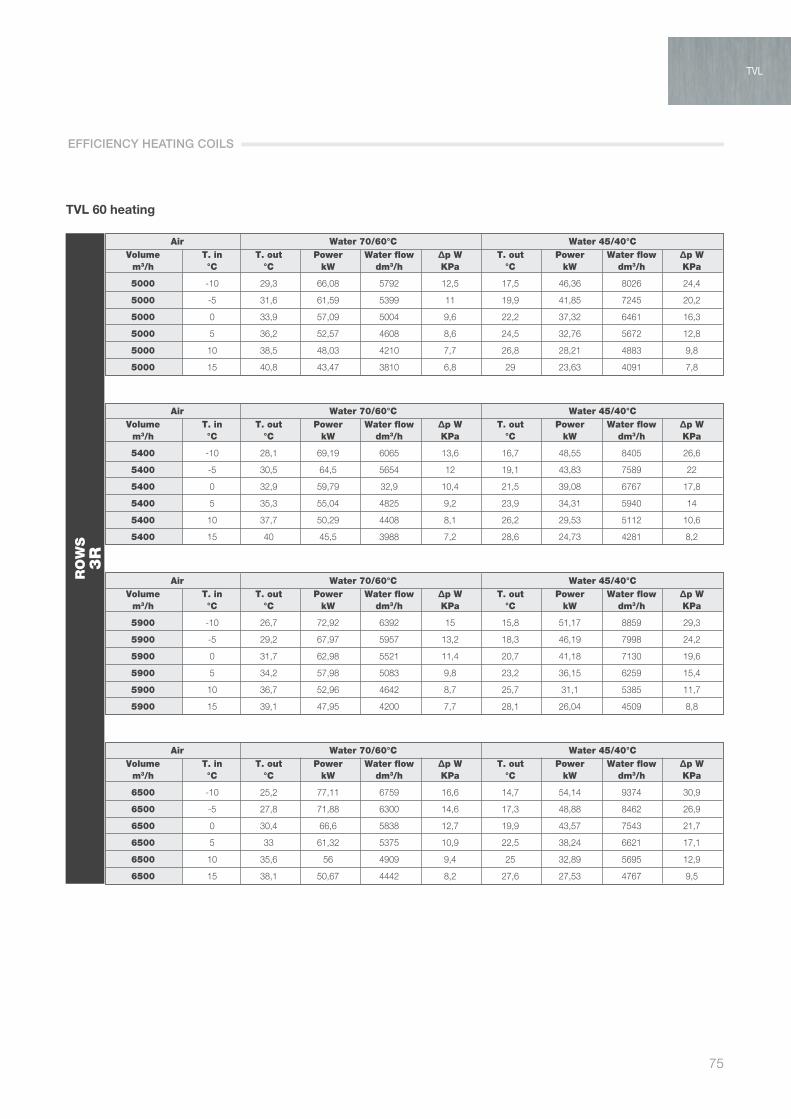
75
TVL
TVL 60 heating
Air Water 70/60°C Water 45/40°C Volume T. in T. out Power Water flow ∆p W T. out Power Water flow ∆p W m3/h °C °C kW dm3/h KPa °C kW dm3/h KPa
5000 -10 29,3 66,08 5792 12,5 17,5 46,36 8026 24,4
5000 -5 31,6 61,59 5399 11 19,9 41,85 7245 20,2
5000 0 33,9 57,09 5004 9,6 22,2 37,32 6461 16,3
5000 5 36,2 52,57 4608 8,6 24,5 32,76 5672 12,8
5000 10 38,5 48,03 4210 7,7 26,8 28,21 4883 9,8
5000 15 40,8 43,47 3810 6,8 29 23,63 4091 7,8
Air Water 70/60°C Water 45/40°C Volume T. in T. out Power Water flow ∆p W T. out Power Water flow ∆p W m3/h °C °C kW dm3/h KPa °C kW dm3/h KPa
5400 -10 28,1 69,19 6065 13,6 16,7 48,55 8405 26,6
5400 -5 30,5 64,5 5654 12 19,1 43,83 7589 22
5400 0 32,9 59,79 32,9 10,4 21,5 39,08 6767 17,8
5400 5 35,3 55,04 4825 9,2 23,9 34,31 5940 14
5400 10 37,7 50,29 4408 8,1 26,2 29,53 5112 10,6
5400 15 40 45,5 3988 7,2 28,6 24,73 4281 8,2
Air Water 70/60°C Water 45/40°C Volume T. in T. out Power Water flow ∆p W T. out Power Water flow ∆p W m3/h °C °C kW dm3/h KPa °C kW dm3/h KPa
5900 -10 26,7 72,92 6392 15 15,8 51,17 8859 29,3
5900 -5 29,2 67,97 5957 13,2 18,3 46,19 7998 24,2
5900 0 31,7 62,98 5521 11,4 20,7 41,18 7130 19,6
5900 5 34,2 57,98 5083 9,8 23,2 36,15 6259 15,4
5900 10 36,7 52,96 4642 8,7 25,7 31,1 5385 11,7
5900 15 39,1 47,95 4200 7,7 28,1 26,04 4509 8,8
Air Water 70/60°C Water 45/40°C Volume T. in T. out Power Water flow ∆p W T. out Power Water flow ∆p W m3/h °C °C kW dm3/h KPa °C kW dm3/h KPa
6500 -10 25,2 77,11 6759 16,6 14,7 54,14 9374 30,9
6500 -5 27,8 71,88 6300 14,6 17,3 48,88 8462 26,9
6500 0 30,4 66,6 5838 12,7 19,9 43,57 7543 21,7
6500 5 33 61,32 5375 10,9 22,5 38,24 6621 17,1
6500 10 35,6 56 4909 9,4 25 32,89 5695 12,9
6500 15 38,1 50,67 4442 8,2 27,6 27,53 4767 9,5
RO
WS
3R
TVL
EFFICIENCY HEATING COILS

AIR TREATMENT
76
TVL 60 heating
Air Water 70/60°C Water 45/40°C Volume T. in T. out Power Water flow ∆p W T. out Power Water flow ∆p W m3/h °C °C kW dm3/h KPa °C kW dm3/h KPa
5000 -10 36,8 78,85 6911 9,8 22,8 55,23 9563 18,9
5000 -5 38,7 73,5 6443 8,8 24,6 49,85 8631 15,5
5000 0 40,5 68,12 5971 8 26,4 44,44 7694 12,5
5000 5 42,3 62,71 5497 7,2 28,2 39,04 6759 9,8
5000 10 44 57,31 5024 6,5 30 33,6 5818 8
5000 15 45,8 51,87 4547 5,8 31,7 28,15 4874 6,5
Air Water 70/60°C Water 45/40°C Volume T. in T. out Power Water flow ∆p W T. out Power Water flow ∆p W m3/h °C °C kW dm3/h KPa °C kW dm3/h KPa
5400 -10 35,5 82,79 7257 10,7 21,9 58,01 10044 20,7
5400 -5 37,5 77,17 6764 9,5 23,8 52,35 9063 17,1
5400 0 39,3 71,5 6267 8,5 25,7 46,67 8080 13,7
5400 5 41,2 65,83 5771 7,7 27,5 40,97 7094 10,7
5400 10 43,1 60,15 5272 7,7 29,4 35,27 6107 8,6
5400 15 44,9 54,44 4772 6,1 31,3 29,55 5116 6,8
Air Water 70/60°C Water 45/40°C Volume T. in T. out Power Water flow ∆p W T. out Power Water flow ∆p W m3/h °C °C kW dm3/h KPa °C kW dm3/h KPa
5900 -10 34 87,49 7669 11,8 20,9 61,32 10617 23
5900 -5 36 81,53 7146 10,4 22,9 55,32 9578 18,9
5900 0 38 75,54 6622 9,2 24,8 49,31 8537 15,2
5900 5 40 69,55 6097 8,2 26,8 43,31 7499 11,9
5900 10 42 63,53 5568 7,3 28,8 37,27 6452 9,2
5900 15 43,9 57,47 5038 6,5 30,7 31,2 5402 7,3
Air Water 70/60°C Water 45/40°C Volume T. in T. out Power Water flow ∆p W T. out Power Water flow ∆p W m3/h °C °C kW dm3/h KPa °C kW dm3/h KPa
6500 -10 32,4 92,81 8135 13,2 19,7 65,09 11269 25,7
6500 -5 34,5 86,5 7583 11,6 21,8 57,72 10166 21,2
6500 0 36,6 80,13 7024 10 23,9 52,33 9060 17
6500 5 38,7 73,78 6467 8,9 26,4 5,94 7954 13,3
6500 10 40,8 67,36 5905 7,9 28,1 39,53 6843 10
6500 15 42,9 60,94 5342 7 30,1 33,09 5729 7,9
RO
WS
4R
EFFICIENCY HEATING COILS

77
TVL
TVL 60 cooling
Air Water 7/12°C Water 8/13°C Volume T. in T. out Power Water flow ∆p W T. out Power Water flow ∆p W m3/h °C °C kW dm3/h KPa °C kW dm3/h KPa
5000 22 / 50% 15,3 11,4 1959 4,1 16 10,22 1757 3,8
5000 24 / 50% 15,9 14,02 2410 4,8 16,6 12,68 2178 4,5
5000 26 / 50% 16,8 17,13 2944 5,8 17,3 15,49 2662 5,3
5000 28 / 50% 17,7 20,66 3551 7,2 18,2 18,86 3242 6,4
5000 32 / 50% 19,7 30,22 5194 12,4 20,1 27,88 4792 10,7
5000 35 / 50% 21,3 38,74 6658 19,5 21,7 36,62 6242 17,3
Air Water 7/12°C Water 8/13°C Volume T. in T. out Power Water flow ∆p W T. out Power Water flow ∆p W m3/h °C °C kW dm3/h KPa °C kW dm3/h KPa
5400 22 / 50% 15,5 11,99 2061 4,3 16,2 10,78 1852 4
5400 24 / 50% 16,1 14,67 2522 5 16,8 13,29 2284 4,6
5400 26 / 50% 17 17,87 3072 6,1 17,6 16,21 2786 5,5
5400 28 / 50% 17,9 21,58 3709 7,5 18,4 19,7 3386 6,8
5400 32 / 50% 20 31,43 5402 13,3 20,4 29 4983 11,5
5400 35 / 50% 21,6 40,24 6933 21 22 37,8 6497 18,6
Air Water 7/12°C Water 8/13°C Volume T. in T. out Power Water flow ∆p W T. out Power Water flow ∆p W m3/h °C °C kW dm3/h KPa °C kW dm3/h KPa
5900 22 / 50% 15,7 12,68 2179 4,5 16,3 11,44 1967 4,1
5900 24 / 50% 16,4 15,47 2659 5,3 17,1 14,01 2408 4,8
5900 26 / 50% 17,2 18,78 3228 6,4 17,8 17,05 2930 5,8
5900 28 / 50% 18,3 22,38 3846 7,9 18,7 20,69 3556 7,2
5900 32 / 50% 20,3 32,88 5652 14,5 20,7 30,31 5208 12,4
5900 35 / 50% 22 42,22 7256 22,9 22,4 39,56 6798 20,2
Air Water 7/12°C Water 8/13°C Volume T. in T. out Power Water flow ∆p W T. out Power Water flow ∆p W m3/h °C °C kW dm3/h KPa °C kW dm3/h KPa
6500 22 / 50% 15,9 13,43 2308 4,7 16,5 12,14 2086 4,3
6500 24 / 50% 16,8 16,08 2765 5,5 17,3 14,83 2548 5,1
6500 26 / 50% 17,6 19,51 3353 6,7 18,1 17,99 3092 6,1
6500 28 / 50% 18,6 23,6 4056 8,4 19 21,74 3736 7,6
6500 32 / 50% 20,6 34,52 5932 15,8 21,2 31,31 5381 13,2
6500 35 / 50% 22,4 44,36 7624 25 22,8 41,53 7137 22,1
RO
WS
4R
Coil performance in cooling mode for each size of unit at different air flows and with different air and water inlet temperatures.
TVL
EFFICIENCY COOLING COILS

AIR TREATMENT
78
TVL 60 cooling
Air Water 7/12°C Water 8/13°C Volume T. in T. out Power Water flow ∆p W T. out Power Water flow ∆p W m3/h °C °C kW dm3/h KPa °C kW dm3/h KPa
5000 22 / 50% 13,6 14,32 2462 4,1 14,4 12,39 2129 3,8
5000 24 / 50% 13,9 18,02 3097 5 14,6 16,29 2800 4,5
5000 26 / 50% 14,7 22,03 3787 6 15,2 20,1 3455 5,5
5000 28 / 50% 15,4 26,86 4616 7,5 16 24,56 4221 6,8
5000 32 / 50% 16,9 39,32 6758 13,6 17,5 36,38 6253 11,7
5000 35 / 50% 18,2 50,2 8627 21,3 18,7 47,15 8104 18,9
Air Water 7/12°C Water 8/13°C Volume T. in T. out Power Water flow ∆p W T. out Power Water flow ∆p W m3/h °C °C kW dm3/h KPa °C kW dm3/h KPa
5400 22 / 50% 13,8 15,23 2618 4,3 14,7 13,53 2326 4
5400 24 / 50% 14,2 18,95 3257 5,2 14,8 17,16 2950 4,7
5400 26 / 50% 14,9 23,08 3966 6,3 15,5 20,94 3599 5,7
5400 28 / 50% 15,7 28,07 4825 8 16,3 25,65 4410 7,1
5400 32 / 50% 17,3 41,06 7056 14,7 17,8 37,99 6529 12,7
5400 35 / 50% 18,5 52,43 9012 23,1 19,1 49,26 8465 20,5
Air Water 7/12°C Water 8/13°C Volume T. in T. out Power Water flow ∆p W T. out Power Water flow ∆p W m3/h °C °C kW dm3/h KPa °C kW dm3/h KPa
5900 22 / 50% 13,9 16,24 2791 4,5 14,8 14,61 2511 4,2
5900 24 / 50% 14,4 20,01 3438 5,5 15,1 18,16 3121 5
5900 26 / 50% 15,2 24,32 4181 6,7 15,8 22,1 3798 6
5900 28 / 50% 16 29,54 5076 8,5 16,5 26,98 4638 7,5
5900 32 / 50% 17,6 43,1 7407 16,1 18,2 39,88 6853 13,9
5900 35 / 50% 19 55,11 9472 25,4 19,5 51,71 8887 22,4
Air Water 7/12°C Water 8/13°C Volume T. in T. out Power Water flow ∆p W T. out Power Water flow ∆p W m3/h °C °C kW dm3/h KPa °C kW dm3/h KPa
6500 22 / 50% 14,2 17,34 2980 4,8 14,9 15,66 2691 4,4
6500 24 / 50% 14,7 21,09 3625 5,8 15,4 19,28 3314 5,3
6500 26 / 50% 15,5 25,7 4417 7,2 16,1 23,43 4027 6,4
6500 28 / 50% 16,3 31,16 5355 9,1 16,9 28,37 4876 8
6500 32 / 50% 18 45,43 7809 17,7 18,6 41,68 7164 15,1
6500 35 / 50% 19,4 58,1 9985 28 19,9 54,53 9371 24,8
RO
WS
6R
EFFICIENCY COOLING COILS

79
TVL
TVL 80 heating
Air Water 70/60°C Water 45/40°C Volume T. in T. out Power Water flow ∆p W T. out Power Water flow ∆p W m3/h °C °C kW dm3/h KPa °C kW dm3/h KPa
7000 -10 17,8 65,57 5748 9,7 9,6 46,13 7987 18,8
7000 -5 20,9 61,11 5356 8,8 12,7 41,63 7207 15,5
7000 0 24 56,63 4964 8 15,7 37,1 6426 12,5
7000 5 27,1 52,12 4569 7,2 18,8 32,55 5636 9,8
7000 10 30,2 47,59 4172 6,5 21,9 27,98 4845 8,1
7000 15 33,3 4305 3774 5,8 24,9 23,4 4051 6,5
Air Water 70/60°C Water 45/40°C Volume T. in T. out Power Water flow ∆p W T. out Power Water flow ∆p W m3/h °C °C kW dm3/h KPa °C kW dm3/h KPa
7600 -10 16,8 68,64 6017 10,4 8,9 48,3 8363 20,5
7600 -5 20 63,97 5607 9,3 12 43,58 7546 16,9
7600 0 23,2 59,28 5196 8,4 15,2 38,84 6725 13,7
7600 5 26,3 54,56 4782 7,6 15,2 38,84 6725 13,7
7600 10 29,5 49,82 4367 6,8 21,4 29,29 5071 8,5
7600 15 32,6 45,05 3949 6,1 24,6 24,49 4240 6,9
Air Water 70/60°C Water 45/40°C Volume T. in T. out Power Water flow ∆p W T. out Power Water flow ∆p W m3/h °C °C kW dm3/h KPa °C kW dm3/h KPa
8300 -10 15,8 72,05 6316 11,4 8,1 50,71 8780 22,4
8300 -5 19 67,14 5886 10 11,4 45,75 7921 18,5
8300 0 22,3 62,21 5453 9 14,6 40,77 7058 14,9
8300 5 25,5 57,25 5019 8,1 17,8 35,76 6192 11,7
8300 10 28,7 52,27 4582 7,2 21 30,74 5322 9,1
8300 15 31,9 47,26 4142 6,4 24,2 25,69 4448 7,3
Air Water 70/60°C Water 45/40°C Volume T. in T. out Power Water flow ∆p W T. out Power Water flow ∆p W m3/h °C °C kW dm3/h KPa °C kW dm3/h KPa
9100 -10 14,7 75,72 6637 12,5 7,4 53,31 9229 24,6
9100 -5 18 70,56 6185 11 10,7 48,09 8326 20,3
9100 0 21,3 65,37 5730 9,6 14 42,85 7418 16,4
9100 5 24,6 60,15 5272 8,6 17,3 37,58 6506 12,8
9100 10 27,9 54,95 4814 7,7 20,5 32,29 5591 9,7
9100 15 31,2 49,64 4351 6,8 23,8 26,98 4672 7,7
RO
WS
2R
Coil performance in heating mode for each size of unit at different air flows and with different air and water inlet temperatures.
TVL
EFFICIENCY HEATING COILS

AIR TREATMENT
80
TVL 80 heating
Air Water 70/60°C Water 45/40°C Volume T. in T. out Power Water flow ∆p W T. out Power Water flow ∆p W m3/h °C °C kW dm3/h KPa °C kW dm3/h KPa
7000 -10 29,2 92,41 8101 16,4 17,5 64,82 11223 32
7000 -5 31,5 86,12 7549 14,4 19,8 58,52 10132 26,4
7000 0 33,9 79,83 6997 12,5 22,1 52,18 9035 21,3
7000 5 36,2 73,5 6443 10,7 24,4 45,81 7931 16,7
7000 10 38,5 67,15 5866 9,2 26,7 39,42 6825 12,6
7000 15 40,8 60,77 5327 8,1 29 33,02 5716 9,3
Air Water 70/60°C Water 45/40°C Volume T. in T. out Power Water flow ∆p W T. out Power Water flow ∆p W m3/h °C °C kW dm3/h KPa °C kW dm3/h KPa
7600 -10 27,9 97,08 8509 18 16,6 68,11 11792 35,1
7600 -5 30,4 90,46 7929 15,8 19 61,49 10647 29
7600 0 32,8 83,84 7349 13,7 21,4 54,81 9490 23,4
7600 5 35,2 77,2 6767 11,7 23,8 48,12 8331 18,3
7600 10 37,6 70,51 6181 9,9 26,2 41,41 7169 13,8
7600 15 39,9 63,82 5594 8,6 28,6 34,66 6002 9,9
Air Water 70/60°C Water 45/40°C Volume T. in T. out Power Water flow ∆p W T. out Power Water flow ∆p W m3/h °C °C kW dm3/h KPa °C kW dm3/h KPa
8300 -10 26,6 102,23 8961 19,9 15,7 71,76 12424 38,7
8300 -5 29,1 95,28 8352 17,4 18,2 64,78 11216 32
8300 0 31,6 88,29 7739 15,1 20,7 57,75 9998 25,8
8300 5 34,1 81,28 7124 12,9 23,1 50,68 8775 20,2
8300 10 36,6 74,25 6509 10,9 25,6 43,6 7549 15,2
8300 15 39 67,18 5889 9,3 28,1 36,5 6319 10,8
Air Water 70/60°C Water 45/40°C Volume T. in T. out Power Water flow ∆p W T. out Power Water flow ∆p W m3/h °C °C kW dm3/h KPa °C kW dm3/h KPa
9100 -10 25,2 107,84 9453 22 14,7 75,72 13109 42,9
9100 -5 27,8 100,5 8810 19,2 17,3 68,35 11833 35,3
9100 0 30,4 93,12 8162 16,7 19,9 60,91 10546 28,5
9100 5 33 85,72 7514 14,3 22,4 53,46 9256 22,4
9100 10 35,5 78,29 6862 12 25 45,98 7960 16,8
9100 15 38,1 70,8 6206 10 27,6 38,48 6662 12,1
RO
WS
3R
EFFICIENCY HEATING COILS

81
TVL
Air Water 70/60°C Water 45/40°C Volume T. in T. out Power Water flow ∆p W T. out Power Water flow ∆p W m3/h °C °C kW dm3/h KPa °C kW dm3/h KPa
7000 -10 36,8 110,39 9676 10 22,8 77,33 13388 19,4
7000 -5 38,7 102,9 9020 9 24,6 69,79 12083 16
7000 0 40,5 95,36 8359 8,2 26,4 62,22 10772 12,9
7000 5 42,3 87,8 7696 7,4 28,2 54,66 9463 10,1
7000 10 44 80,24 7034 6,6 30 47,05 8146 8,2
7000 15 45,8 72,62 6366 5,9 31,7 39,41 6824 6,6
Air Water 70/60°C Water 45/40°C Volume T. in T. out Power Water flow ∆p W T. out Power Water flow ∆p W m3/h °C °C kW dm3/h KPa °C kW dm3/h KPa
7600 -10 35,5 116,3 10195 11,1 21,9 81,49 14109 21,5
7600 -5 37,4 108,38 9500 9,7 23,7 73,53 12732 17,7
7600 0 39,3 100,44 8805 8,8 25,6 65,54 11348 14,2
7600 5 41,1 92,48 8107 7,8 27,5 57,57 9967 11,1
7600 10 43 84,46 7403 7 29,4 49,55 8578 8,8
7600 15 44,9 76,44 6701 6,3 31,2 41,5 7186 7
Air Water 70/60°C Water 45/40°C Volume T. in T. out Power Water flow ∆p W T. out Power Water flow ∆p W m3/h °C °C kW dm3/h KPa °C kW dm3/h KPa
8300 -10 34 122,86 10769 12,3 20,8 86,11 14908 23,8
8300 -5 36 114,48 10036 10,7 22,8 77,69 13451 19,6
8300 0 38 106,08 9299 9,4 24,8 69,24 11988 15,8
8300 5 39,9 97,65 8559 8,4 26,8 60,8 10526 12,3
8300 10 41,9 89,21 7820 7,5 28,7 52,32 9057 9,4
8300 15 43,9 80,71 7075 6,7 30,7 43,81 7586 7,5
Air Water 70/60°C Water 45/40°C Volume T. in T. out Power Water flow ∆p W T. out Power Water flow ∆p W m3/h °C °C kW dm3/h KPa °C kW dm3/h KPa
9100 -10 32,4 129,94 11390 13,6 19,7 91,12 15777 26,5
9100 -5 34,5 121,1 10616 11,9 21,8 82,2 14232 21,8
9100 0 36,6 112,19 9834 10,3 23,8 73,26 12685 17,6
9100 5 38,7 103,29 9054 9,1 26 64,32 11135 13,7
9100 10 40,8 94,31 8267 8,1 28,1 55,34 9581 10,3
9100 15 42,9 85,32 7479 7,1 30,1 46,32 8020 8
RO
WS
4R
TVL 80 heating
TVL
EFFICIENCY HEATING COILS

AIR TREATMENT
82
TVL 80 cooling
Air Water 7/12°C Water 8/13°C Volume T. in T. out Power Water flow ∆p W T. out Power Water flow ∆p W m3/h °C °C kW dm3/h KPa °C kW dm3/h KPa
7000 22 / 50% 18,4 8,67 1490 2,8 18,7 7,82 1345 2,7
7000 24 / 50% 19,6 10,44 1794 2,9 20 9,56 1644 2,8
7000 26 / 50% 17,4 21,29 3660 4 18,4 18,21 3130 3,6
7000 28 / 50% 18,2 26,5 4554 4,7 18,6 24,34 4182 4,4
7000 32 / 50% 20,1 39,36 6766 7 20,6 35,7 6135 6,2
7000 35 / 50% 21,7 51,06 8776 9,7 22,1 47,68 8195 8,8
Air Water 7/12°C Water 8/13°C Volume T. in T. out Power Water flow ∆p W T. out Power Water flow ∆p W m3/h °C °C kW dm3/h KPa °C kW dm3/h KPa
7600 22 / 50% 18,6 8,9 1530 2,8 18,9 8,03 1380 2,7
7600 24 / 50% 19,9 10,72 1843 2,9 20,2 9,82 1688 2,8
7600 26 / 50% 17,6 22,47 3862 4,1 18,4 19,8 3403 3,8
7600 28 / 50% 18,4 27,77 4773 4,9 18,9 25,53 4387 4,5
7600 32 / 50% 20,4 41,03 7053 7,7 20,9 37,25 6401 6,5
7600 35 / 50% 22 53,25 9152 10,5 22,4 49,73 8546 9,4
Air Water 7/12°C Water 8/13°C Volume T. in T. out Power Water flow ∆p W T. out Power Water flow ∆p W m3/h °C °C kW dm3/h KPa °C kW dm3/h KPa
8300 22 / 50% 18,8 9,14 1571 2,8 19,1 8,24 1416 2,8
8300 24 / 50% 17,7 17,99 3093 3,6 20,4 10,1 1735 2,8
8300 26 / 50% 17,9 23,83 4096 4,3 18,6 21,25 3651 4
8300 28 / 50% 18,7 29,17 5014 5,1 19,1 26,81 4608 4,7
8300 32 / 50% 20,7 42,84 7364 7,7 21,2 38,95 6694 6,9
8300 35 / 50% 22,4 55,67 9569 11,4 22,8 51,96 8929 10
Air Water 7/12°C Water 8/13°C Volume T. in T. out Power Water flow ∆p W T. out Power Water flow ∆p W m3/h °C °C kW dm3/h KPa °C kW dm3/h KPa
9100 22 / 50% 19 9,39 1615 2,8 19,3 8,46 1454 2,8
9100 24 / 50% 17,6 18,82 3406 3,8 20,7 10,37 1783 2,8
9100 26 / 50% 18,1 25,17 4326 4,5 18,8 22,56 3877 4,1
9100 28 / 50% 19 30,66 5270 5,3 19,6 27,66 4754 4,8
9100 32 / 50% 21,2 44,01 7563 8 21,5 80,83 7,016 7,3
9100 35 / 50% 22,8 58,28 10017 12,4 23,1 54,37 9343 10,9
RO
WS
4R
Coil performance in cooling mode for each size of unit at different air flows and with different air and water inlet temperatures.
EFFICIENCY COOLING COILS

83
TVL
TVL 80 cooling
Air Water 7/12°C Water 8/13°C Volume T. in T. out Power Water flow ∆p W T. out Power Water flow ∆p W m3/h °C °C kW dm3/h KPa °C kW dm3/h KPa
7000 22 / 50% 13,6 20,05 3447 4,1 14,8 17,34 2980 3,8
7000 24 / 50% 13,9 25,21 4333 5 14,6 22,8 3919 4,5
7000 26 / 50% 14,7 30,81 5295 6 15,2 28,12 4832 5,5
7000 28 / 50% 15,4 37,57 6457 7,6 16 34,33 5900 6,8
7000 32 / 50% 16,9 54,9 9436 13,7 17,5 50,84 8738 11,8
7000 35 / 50% 18,2 70,07 12044 21,5 18,8 65,83 11313 19
Air Water 7/12°C Water 8/13°C Volume T. in T. out Power Water flow ∆p W T. out Power Water flow ∆p W m3/h °C °C kW dm3/h KPa °C kW dm3/h KPa
7600 22 / 50% 13,8 21,4 3678 4,3 14,7 19,01 2367 4
7600 24 / 50% 14,2 26,57 4567 5,2 14,9 24,09 4141 4,8
7600 26 / 50% 14,9 32,38 5566 6,4 15,5 29,4 5053 5,7
7600 28 / 50% 15,7 39,37 6799 8 16,3 35,98 6184 7,2
7600 32 / 50% 17,3 57,46 9875 14,9 17,9 53,2 9143 12,8
7600 35 / 50% 18,6 73,42 12619 23,4 19,1 68,97 11853 20,8
Air Water 7/12°C Water 8/13°C Volume T. in T. out Power Water flow ∆p W T. out Power Water flow ∆p W m3/h °C °C kW dm3/h KPa °C kW dm3/h KPa
8300 22 / 50% 13,9 22,83 3924 4,6 14,8 20,52 3526 4,2
8300 24 / 50% 14,4 28,08 4826 5,5 15,1 25,5 4382 5
8300 26 / 50% 15,2 34,07 5856 6,7 15,8 31,02 5331 6,1
8300 28 / 50% 16 41,4 7115 8,6 16,6 37,83 6501 7,6
8300 32 / 50% 17,7 60,33 10369 16,3 18,2 55,78 9586 14
8300 35 / 50% 19 77,13 13256 25,7 19,6 72,38 12436 22,7
Air Water 7/12°C Water 8/13°C Volume T. in T. out Power Water flow ∆p W T. out Power Water flow ∆p W m3/h °C °C kW dm3/h KPa °C kW dm3/h KPa
9100 22 / 50% 14,2 24,28 4172 4,8 14,9 21,92 3767 4,4
9100 24 / 50% 14,7 29,52 5073 5,8 15,4 26,99 4638 5,3
9100 26 / 50% 15,5 35,94 6177 7,2 16,1 32,78 5634 6,4
9100 28 / 50% 16,4 43,54 7484 9,1 16,9 39,67 6817 8,1
9100 32 / 50% 18,1 63,42 10900 17,8 18,6 58,21 10004 15,2
9100 35 / 50% 19,5 81,08 13935 28,2 20 76,1 13078 24,9
RO
WS
6R
TVL
EFFICIENCY HEATING COILS
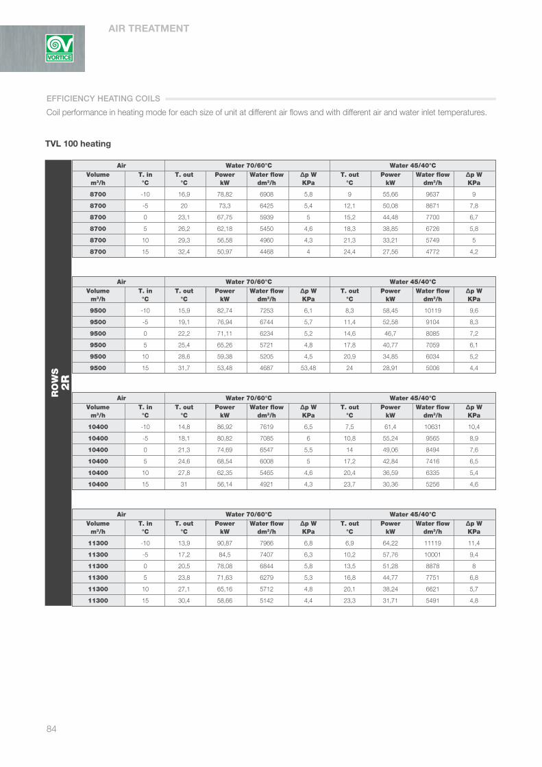
AIR TREATMENT
84
TVL 100 heating
Air Water 70/60°C Water 45/40°C Volume T. in T. out Power Water flow ∆p W T. out Power Water flow ∆p W m3/h °C °C kW dm3/h KPa °C kW dm3/h KPa
8700 -10 16,9 78,82 6908 5,8 9 55,66 9637 9
8700 -5 20 73,3 6425 5,4 12,1 50,08 8671 7,8
8700 0 23,1 67,75 5939 5 15,2 44,48 7700 6,7
8700 5 26,2 62,18 5450 4,6 18,3 38,85 6726 5,8
8700 10 29,3 56,58 4960 4,3 21,3 33,21 5749 5
8700 15 32,4 50,97 4468 4 24,4 27,56 4772 4,2
Air Water 70/60°C Water 45/40°C Volume T. in T. out Power Water flow ∆p W T. out Power Water flow ∆p W m3/h °C °C kW dm3/h KPa °C kW dm3/h KPa
9500 -10 15,9 82,74 7253 6,1 8,3 58,45 10119 9,6
9500 -5 19,1 76,94 6744 5,7 11,4 52,58 9104 8,3
9500 0 22,2 71,11 6234 5,2 14,6 46,7 8085 7,2
9500 5 25,4 65,26 5721 4,8 17,8 40,77 7059 6,1
9500 10 28,6 59,38 5205 4,5 20,9 34,85 6034 5,2
9500 15 31,7 53,48 4687 53,48 24 28,91 5006 4,4
Air Water 70/60°C Water 45/40°C Volume T. in T. out Power Water flow ∆p W T. out Power Water flow ∆p W m3/h °C °C kW dm3/h KPa °C kW dm3/h KPa
10400 -10 14,8 86,92 7619 6,5 7,5 61,4 10631 10,4
10400 -5 18,1 80,82 7085 6 10,8 55,24 9565 8,9
10400 0 21,3 74,69 6547 5,5 14 49,06 8494 7,6
10400 5 24,6 68,54 6008 5 17,2 42,84 7416 6,5
10400 10 27,8 62,35 5465 4,6 20,4 36,59 6335 5,4
10400 15 31 56,14 4921 4,3 23,7 30,36 5256 4,6
Air Water 70/60°C Water 45/40°C Volume T. in T. out Power Water flow ∆p W T. out Power Water flow ∆p W m3/h °C °C kW dm3/h KPa °C kW dm3/h KPa
11300 -10 13,9 90,87 7966 6,8 6,9 64,22 11119 11,4
11300 -5 17,2 84,5 7407 6,3 10,2 57,76 10001 9,4
11300 0 20,5 78,08 6844 5,8 13,5 51,28 8878 8
11300 5 23,8 71,63 6279 5,3 16,8 44,77 7751 6,8
11300 10 27,1 65,16 5712 4,8 20,1 38,24 6621 5,7
11300 15 30,4 58,66 5142 4,4 23,3 31,71 5491 4,8
RO
WS
2R
Coil performance in heating mode for each size of unit at different air flows and with different air and water inlet temperatures.
EFFICIENCY HEATING COILS
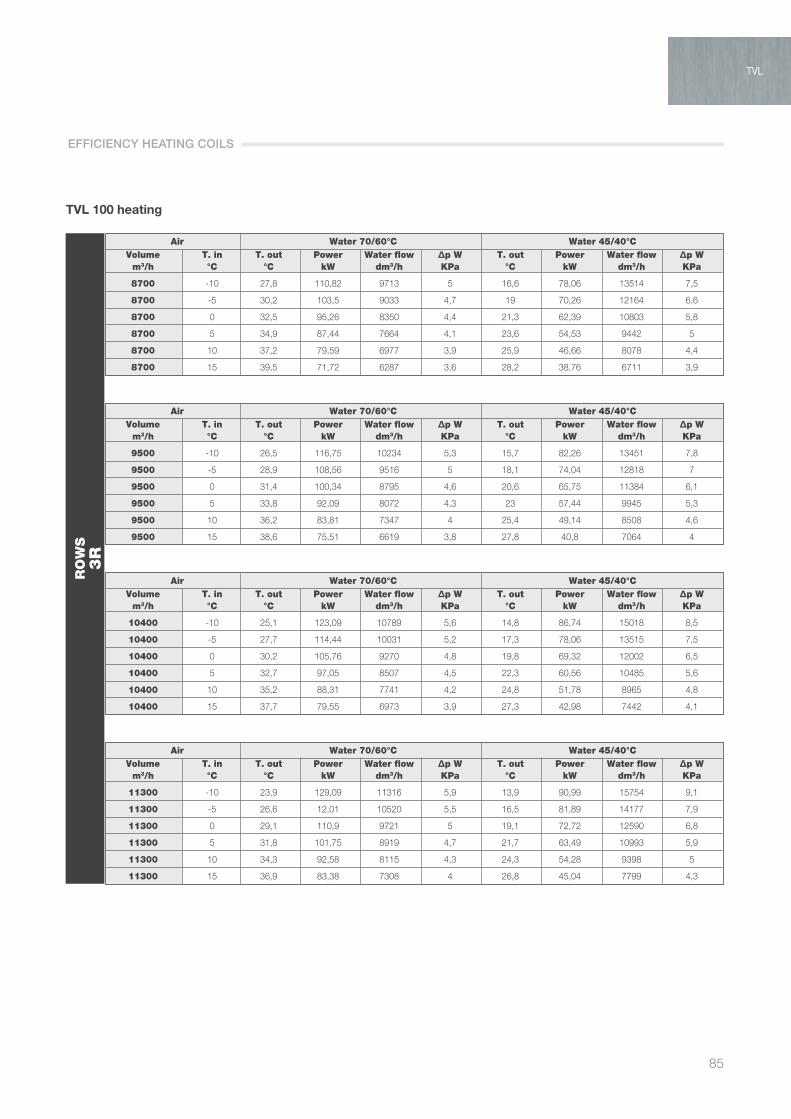
85
TVL
TVL 100 heating
Air Water 70/60°C Water 45/40°C Volume T. in T. out Power Water flow ∆p W T. out Power Water flow ∆p W m3/h °C °C kW dm3/h KPa °C kW dm3/h KPa
8700 -10 27,8 110,82 9713 5 16,6 78,06 13514 7,5
8700 -5 30,2 103,5 9033 4,7 19 70,26 12164 6,6
8700 0 32,5 95,26 8350 4,4 21,3 62,39 10803 5,8
8700 5 34,9 87,44 7664 4,1 23,6 54,53 9442 5
8700 10 37,2 79,59 6977 3,9 25,9 46,66 8078 4,4
8700 15 39,5 71,72 6287 3,6 28,2 38,76 6711 3,9
Air Water 70/60°C Water 45/40°C Volume T. in T. out Power Water flow ∆p W T. out Power Water flow ∆p W m3/h °C °C kW dm3/h KPa °C kW dm3/h KPa
9500 -10 26,5 116,75 10234 5,3 15,7 82,26 13451 7,8
9500 -5 28,9 108,56 9516 5 18,1 74,04 12818 7
9500 0 31,4 100,34 8795 4,6 20,6 65,75 11384 6,1
9500 5 33,8 92,09 8072 4,3 23 57,44 9945 5,3
9500 10 36,2 83,81 7347 4 25,4 49,14 8508 4,6
9500 15 38,6 75,51 6619 3,8 27,8 40,8 7064 4
Air Water 70/60°C Water 45/40°C Volume T. in T. out Power Water flow ∆p W T. out Power Water flow ∆p W m3/h °C °C kW dm3/h KPa °C kW dm3/h KPa
10400 -10 25,1 123,09 10789 5,6 14,8 86,74 15018 8,5
10400 -5 27,7 114,44 10031 5,2 17,3 78,06 13515 7,5
10400 0 30,2 105,76 9270 4,8 19,8 69,32 12002 6,5
10400 5 32,7 97,05 8507 4,5 22,3 60,56 10485 5,6
10400 10 35,2 88,31 7741 4,2 24,8 51,78 8965 4,8
10400 15 37,7 79,55 6973 3,9 27,3 42,98 7442 4,1
Air Water 70/60°C Water 45/40°C Volume T. in T. out Power Water flow ∆p W T. out Power Water flow ∆p W m3/h °C °C kW dm3/h KPa °C kW dm3/h KPa
11300 -10 23,9 129,09 11316 5,9 13,9 90,99 15754 9,1
11300 -5 26,6 12,01 10520 5,5 16,5 81,89 14177 7,9
11300 0 29,1 110,9 9721 5 19,1 72,72 12590 6,8
11300 5 31,8 101,75 8919 4,7 21,7 63,49 10993 5,9
11300 10 34,3 92,58 8115 4,3 24,3 54,28 9398 5
11300 15 36,9 83,38 7308 4 26,8 45,04 7799 4,3
RO
WS
3R
TVL
EFFICIENCY HEATING COILS

AIR TREATMENT
86
TVL 100 heating
Air Water 70/60°C Water 45/40°C Volume T. in T. out Power Water flow ∆p W T. out Power Water flow ∆p W m3/h °C °C kW dm3/h KPa °C kW dm3/h KPa
8700 -10 37,5 139,06 12189 16,8 23,2 88,23 15275 5,6
8700 -5 39,3 129,68 11367 14,7 22,1 79,41 13749 5,1
8700 0 41,1 120,26 10541 12,7 24,1 70,56 12216 4,6
8700 5 42,8 110,84 9716 10,9 26,1 61,73 10688 4,2
8700 10 44,6 101,39 8888 9,4 28,1 52,86 9152 3,8
8700 15 46,4 91,87 8052 8,2 30 43,96 7611 3,5
Air Water 70/60°C Water 45/40°C Volume T. in T. out Power Water flow ∆p W T. out Power Water flow ∆p W m3/h °C °C kW dm3/h KPa °C kW dm3/h KPa
9500 -10 36 147,03 12888 18,6 22,2 102,91 17816 36,1
9500 -5 37,9 137,12 12716 16,3 24,1 92,94 16090 29,8
9500 0 39,8 127,16 11147 14,2 25,9 82,93 14358 24
9500 5 41,6 117,17 10270 12,1 27,8 72,94 12629 18,9
9500 10 43,5 107,18 9395 10,3 29,7 62,89 10888 14,3
9500 15 45,4 97,11 8512 8,8 31,5 52,79 9140 10,3
Air Water 70/60°C Water 45/40°C Volume T. in T. out Power Water flow ∆p W T. out Power Water flow ∆p W m3/h °C °C kW dm3/h KPa °C kW dm3/h KPa
10400 -10 34,4 155,58 13638 20,7 21 108 18600 55
10400 -5 36,4 14506 12716 18,1 23,1 98,37 17031 33,1
10400 0 38,4 134,53 11792 15,7 25,1 87,76 15194 26,7
10400 5 40,4 123,96 10866 13,5 27 77,15 13357 21
10400 10 42,4 113,34 9935 11,4 29 66,54 11520 15,9
10400 15 44,3 102,69 9001 9,6 30,9 55,82 9665 11,4
Air Water 70/60°C Water 45/40°C Volume T. in T. out Power Water flow ∆p W T. out Power Water flow ∆p W m3/h °C °C kW dm3/h KPa °C kW dm3/h KPa
11300 -10 33 163,7 14350 22,8 - - - -
11300 -5 35,1 152,61 13377 20 22,2 103,5 17920 36,5
11300 0 37,2 141,52 12405 17,3 24,3 92,35 15988 29,4
11300 5 39,3 130,4 11430 14,8 26,4 81,2 14058 23,1
11300 10 41,3 119,23 10452 12,5 28,4 69,98 12116 17,4
11300 15 43,4 108,03 9469 10,4 30,4 58,73 10168 12,5
RO
WS
4R
- Contact our Technical/Sales Department
EFFICIENCY HEATING COILS

87
TVL
TVL 100 cooling
Air Water 7/12°C Water 8/13°C Volume T. in T. out Power Water flow ∆p W T. out Power Water flow ∆p W m3/h °C °C kW dm3/h KPa °C kW dm3/h KPa
8700 22 / 50% - - - - - - - -
8700 24 / 50% 16,1 23,53 4045 4,4 16,9 21,06 3620 4,1
8700 26 / 50% 16,9 28,92 4971 5,3 17,5 26,2 4502 4,8
8700 28 / 50% 17,9 34,59 5946 6,4 18,4 31,98 5496 5,9
8700 32 / 50% 19,8 51,22 8803 10,7 20,3 47,2 8111 9,3
8700 35 / 50% 22,4 79,45 13656 24,3 22,9 75,11 12908 21,8
Air Water 7/12°C Water 8/13°C Volume T. in T. out Power Water flow ∆p W T. out Power Water flow ∆p W m3/h °C °C kW dm3/h KPa °C kW dm3/h KPa
9500 22 / 50% 16,1 19,08 3279 3,8 18,9 10,03 1724 2,9
9500 24 / 50% 16,5 24,51 4213 4,6 17,1 22,4 3850 4,3
9500 26 / 50% 17,3 29,97 5150 5,5 17,8 27,59 4747 5,1
9500 28 / 50% 18,2 36,37 6250 6,8 18,6 33,59 5773 6,2
9500 32 / 50% 20,1 53,61 9213 11,7 20,7 48,62 8355 9,7
9500 35 / 50% 22,8 83,2 14300 26,4 23,2 78,62 13511 23,7
Air Water 7/12°C Water 8/13°C Volume T. in T. out Power Water flow ∆p W T. out Power Water flow ∆p W m3/h °C °C kW dm3/h KPa °C kW dm3/h KPa
10400 22 / 50% 16,4 19,8 3404 4,2 19,3 9,73 1673 3
10400 24 / 50% 17,1 24,47 4206 4,8 17,7 22,46 3861 4,5
10400 26 / 50% 18 29,8 5122 5,8 18,4 27,45 4718 5,3
10400 28 / 50% 19 36,13 6209 7,1 19,4 33,25 5714 6,5
10400 32 / 50% 21,1 52,98 9106 12,1 21,6 48,1 8266 10,2
10400 35 / 50% 23,2 87,17 14982 28,9 23,6 82,32 14148 25,8
Air Water 7/12°C Water 8/13°C Volume T. in T. out Power Water flow ∆p W T. out Power Water flow ∆p W m3/h °C °C kW dm3/h KPa °C kW dm3/h KPa
11300 22 / 50% 16,1 20,97 3604 4,1 - - - -
11300 24 / 50% 16,7 25,91 4453 4,8 17,3 23,78 4088 4,5
11300 26 / 50% 17,5 31,56 5424 5,8 18 29,07 4998 5,3
11300 28 / 50% 18,5 38,25 6575 7,2 18,9 35,2 6050 6,5
11300 32 / 50% 20,5 56,1 9642 12,7 21 50,92 8752 10,6
11300 35 / 50% 23,6 90,9 15623 31,2 23,9 85,82 14749 27,9
RO
WS
4R
- Contact our Technical/Sales Department
Coil performance in cooling mode for each size of unit at different air flows and with different air and water inlet temperatures.
TVL
EFFICIENCY COOLING COILS

AIR TREATMENT
88
TVL 100 cooling
Air Water 7/12°C Water 8/13°C Volume T. in T. out Power Water flow ∆p W T. out Power Water flow ∆p W m3/h °C °C kW dm3/h KPa °C kW dm3/h KPa
8700 22 / 50% 13,1 26,72 4592 5,6 13,9 24,18 4155 5,1
8700 24 / 50% 13,7 32,65 5611 6,9 14,3 29,62 5090 6,2
8700 26 / 50% 14,4 39,9 6857 8,8 15 36,31 6241 7,8
8700 28 / 50% 15,2 48,59 8352 12,2 15,8 44,32 7617
8700 32 / 50% 16,7 70,38 12096 24,1 17,3 65,31 11223 20,9
8700 35 / 50% 17,9 89,38 15363 37,5 18,5 84,13 14458 33,4
Air Water 7/12°C Water 8/13°C Volume T. in T. out Power Water flow ∆p W T. out Power Water flow ∆p W m3/h °C °C kW dm3/h KPa °C kW dm3/h KPa
9500 22 / 50% 13,3 28,15 4839 5,9 14,1 25,66 4410 5,3
9500 24 / 50% 13,9 34,52 5933 7,4 14,6 31,34 5386 6,6
9500 26 / 50% 14,7 41,88 7198 9,4 15,3 38,29 6581 8,4
9500 28 / 50% 15,5 50,87 8744 13,3 16,1 46,6 8009 11,2
9500 32 / 50% 17,8 73,93 12706 26,4 17,6 68,65 11798 22,9
9500 35 / 50% 18,4 93,98 16152 41,2 18,9 88,49 15207 36,7
Air Water 7/12°C Water 8/13°C Volume T. in T. out Power Water flow ∆p W T. out Power Water flow ∆p W m3/h °C °C kW dm3/h KPa °C kW dm3/h KPa
10400 22 / 50% 13,6 29,9 5139 6,3 14,4 27,2 4675 5,7
10400 24 / 50% 14,2 34,47 6267 7,9 14,8 33,15 5696 7
10400 26 / 50% 15 44,14 7587 10,2 15,5 40,43 6949 9
10400 28 / 50% 15,8 53,58 9210 14,6 16,4 49,05 8429 12,3
10400 32 / 50% 17,5 77,77 13367 29 18 72,1 12390 25,1
10400 35 / 50% 18,8 98,88 16995 45,3 19,4 93,03 15988 40,2
Air Water 7/12°C Water 8/13°C Volume T. in T. out Power Water flow ∆p W T. out Power Water flow ∆p W m3/h °C °C kW dm3/h KPa °C kW dm3/h KPa
11300 22 / 50% 13,8 31,51 5416 6,6 14,6 28,65 4925 6
11300 24 / 50% 14,4 38,3 6584 8,4 15,1 34,89 5996 7,5
11300 26 / 50% 15,3 46,42 7978 11,2 15,8 42,31 7272 9,5
11300 28 / 50% 16,1 56,14 9649 15,9 16,6 51,46 8844 13,5
11300 32 / 50% 17,8 81,4 13990 31,6 18,3 75,4 12958 27,3
11300 35 / 50% 19,2 103,59 17804 49,3 19,7 97,31 16727 43,8
RO
WS
6R
EFFICIENCY COOLING COILS

89
TVL
TVL 120 heating
Air Water 70/60°C Water 45/40°C Volume T. in T. out Power Water flow ∆p W T. out Power Water flow ∆p W m3/h °C °C kW dm3/h KPa °C kW dm3/h KPa
10400 -10 17,4 95,78 8396 7,5 9,3 67,53 11692 13,2
10400 -5 20,5 89,15 7815 6,9 12,4 60,84 10533 10,8
10400 0 23,6 82,5 7231 6,3 15,5 54,11 9369 8,9
10400 5 26,6 75,8 6645 5,7 18,5 47,36 8200 7,5
10400 10 29,7 69,08 6055 5,2 21,6 40,57 7025 6,3
10400 15 32,8 62,33 5464 4,8 24,6 33,78 5849 5,2
Air Water 70/60°C Water 45/40°C Volume T. in T. out Power Water flow ∆p W T. out Power Water flow ∆p W m3/h °C °C kW dm3/h KPa °C kW dm3/h KPa
11300 -10 16,4 100,3 8792 8 8,6 70,74 12247 14,4
11300 -5 19,5 93,35 8183 7,3 11,8 63,72 11032 11,8
11300 0 22,7 86,38 7571 6,6 14,9 56,67 9811 9,5
11300 5 25,9 79,36 6957 6 18 49,58 8584 8
11300 10 29 72,31 6339 5,5 21,2 42,48 7355 6,6
11300 15 32,1 65,24 5718 4,9 24,3 35,36 6121 5,4
Air Water 70/60°C Water 45/40°C Volume T. in T. out Power Water flow ∆p W T. out Power Water flow ∆p W m3/h °C °C kW dm3/h KPa °C kW dm3/h KPa
12400 -10 15,3 105,53 9250 8,5 7,8 74,43 12887 15,8
12400 -5 18,5 98,21 8609 7,8 11,1 67,05 11609 13
12400 0 21,8 90,86 7695 7 14,3 59,61 10321 10,4
12400 5 25 83,48 7317 6,4 17,5 52,16 9030 8,5
12400 10 28,2 76,05 6667 5,8 20,7 44,67 7735 7
12400 15 31,4 68,6 6013 5,2 23,9 37,17 6436 5,7
Air Water 70/60°C Water 45/40°C Volume T. in T. out Power Water flow ∆p W T. out Power Water flow ∆p W m3/h °C °C kW dm3/h KPa °C kW dm3/h KPa
13600 -10 14,2 110,91 9722 9,1 7,1 78,24 13546 17,4
13600 -5 17,5 103,21 9047 8,3 10,4 70,48 12202 14,3
13600 0 20,9 85,48 8369 7,5 13,7 62,66 10848 11,4
13600 5 24,2 87,7 7688 6,7 17 54,8 9488 9,1
13600 10 27,4 79,9 7003 6,1 20,3 46,94 8126 7,4
13600 15 30,7 72,05 6316 5,4 23,5 39,03 6758 6
RO
WS
2R
Coil performance in heating mode for each size of unit at different air flows and with different air and water inlet temperatures.
TVL
EFFICIENCY HEATING COILS

AIR TREATMENT
90
TVL 120 heating
Air Water 70/60°C Water 45/40°C Volume T. in T. out Power Water flow ∆p W T. out Power Water flow ∆p W m3/h °C °C kW dm3/h KPa °C kW dm3/h KPa
10400 -10 28,4 134,6 11799 6,4 17 94,67 16390 10,1
10400 -5 30,8 125,29 10982 5,9 19,4 85,3 14769 8,7
10400 0 33,1 115,93 10161 5,4 21,7 75,88 13137 7,5
10400 5 35,4 106,54 9339 5 24 66,44 11502 6,4
10400 10 37,7 97,12 8513 4,6 26,3 56,96 9862 5,4
10400 15 40 87,66 7684 4,3 28,6 47,46 8218 4,6
Air Water 70/60°C Water 45/40°C Volume T. in T. out Power Water flow ∆p W T. out Power Water flow ∆p W m3/h °C °C kW dm3/h KPa °C kW dm3/h KPa
11300 -10 27,2 141,43 12397 6,8 14,7 93,97 16270 10,6
11300 -5 29,6 131,63 11538 6,2 17,3 84,66 14658 9,1
11300 0 32 121,78 10675 5,7 19,8 75,3 13038 7,8
11300 5 34,4 111,92 9810 5,3 22,3 65,91 11412 6,7
11300 10 36,8 102 8941 4,8 24,9 56,5 9783 5,7
11300 15 39,2 92,05 8069 4,4 27,4 47,07 8150 4,8
Air Water 70/60°C Water 45/40°C Volume T. in T. out Power Water flow ∆p W T. out Power Water flow ∆p W m3/h °C °C kW dm3/h KPa °C kW dm3/h KPa
12400 -10 23,8 141,05 12364 7,1 13,8 99,26 17186 11,7
12400 -5 26,4 131,27 11506 6,6 16,4 89,42 15482 9,8
12400 0 29,1 121,44 10645 6 19,1 79,53 13769 8,4
12400 5 31,7 111,57 9780 5,5 21,7 69,61 12051 7,1
12400 10 34,4 101,68 8913 5,1 24,3 59,65 10327 6
12400 15 37 91,75 8043 4,7 26,9 49,67 8600 5
Air Water 70/60°C Water 45/40°C Volume T. in T. out Power Water flow ∆p W T. out Power Water flow ∆p W m3/h °C °C kW dm3/h KPa °C kW dm3/h KPa
13600 -10 22,5 148,77 13040 7,6 12,9 104,72 18131 13
13600 -5 25,2 138,43 12134 7 15,6 94,33 16332 10,6
13600 0 28 128,06 11225 6,4 18,3 83,89 14524 9
13600 5 30,7 117,64 10312 5,8 21 73,4 12709 7,6
13600 10 33,4 107,19 9395 5,3 23,7 62,89 10888 6,4
13600 15 36,1 96,7 8476 4,9 26,4 52,36 9065 5,3
RO
WS
3R
EFFICIENCY HEATING COILS

91
TVL 120 heating
Air Water 70/60°C Water 45/40°C Volume T. in T. out Power Water flow ∆p W T. out Power Water flow ∆p W m3/h °C °C kW dm3/h KPa °C kW dm3/h KPa
10400 -10 33,5 152,38 13357 5 24 126 21600 45
10400 -5 35,5 141,85 12434 4,7 25,3 105,98 18349 41
10400 0 37,5 131,29 11509 4,5 27 94,66 16389 33,1
10400 5 39,5 120,7 10580 4,2 28,8 83,34 14428 26,1
10400 10 41,4 110,06 9647 4 30,5 71,92 12452 19,8
10400 15 43,4 99,4 8713 3,7 32,3 60,49 10473 14,3
Air Water 70/60°C Water 45/40°C Volume T. in T. out Power Water flow ∆p W T. out Power Water flow ∆p W m3/h °C °C kW dm3/h KPa °C kW dm3/h KPa
11300 -10 36,5 176,87 15504 28,3 - - - -
11300 -5 38,4 165,01 14465 24,8 - - - -
11300 0 40,2 153,1 14320 21,6 26,2 99,82 17282 36,6
11300 5 42,1 141,19 12376 18,5 28,1 87,87 15214 28,8
11300 10 44 129,23 11328 15,7 29,9 75,84 13130 21,8
11300 15 45,8 117,17 10271 13 31,8 63,75 11037 15,8
Air Water 70/60°C Water 45/40°C Volume T. in T. out Power Water flow ∆p W T. out Power Water flow ∆p W m3/h °C °C kW dm3/h KPa °C kW dm3/h KPa
12400 -10 34,9 187,43 16429 31,6 - - - -
12400 -5 36,9 174,89 15330 27,7 - - - -
12400 0 38,9 162,3 14227 24,1 25,3 105,79 18316 40,8
12400 5 40,8 149,58 13111 20,6 27,3 93,15 16127 32,1
12400 10 42,8 136,89 11999 17,5 29,3 80,35 13911 24,3
12400 15 44,7 124,16 10883 14,5 31,2 67,57 11698 17,6
Air Water 70/60°C Water 45/40°C Volume T. in T. out Power Water flow ∆p W T. out Power Water flow ∆p W m3/h °C °C kW dm3/h KPa °C kW dm3/h KPa
13600 -10 33,3 198,36 17387 35,2 - - - -
13600 -5 35,4 185,11 16227 30,9 - - - -
13600 0 37,5 171,74 15055 26,8 - - - -
13600 5 39,6 158,32 13878 23 26,5 98,54 17060 35,7
13600 10 41,6 144,83 12695 19,4 28,6 85,03 14721 27,1
13600 15 43,7 131,34 11513 16,2 30,6 71,51 12382 19,6
RO
WS
4R
- Contact our Technical/Sales Department
Coil performance in heating mode for each size of unit at different air flows and with different air and water inlet temperatures.
TVL
EFFICIENCY HEATING COILS

AIR TREATMENT
92
TVL 120 cooling
Air Water 7/12°C Water 8/13°C Volume T. in T. out Power Water flow ∆p W T. out Power Water flow ∆p W m3/h °C °C kW dm3/h KPa °C kW dm3/h KPa
10400 22 / 50% 15,2 24,03 4130 4,7 15,9 21,56 3705 4,3
10400 24 / 50% 15,9 29,44 5059 5,7 16,5 26,63 4577 5,1
10400 26 / 50% 16,7 35,94 6178 7 17,3 32,53 5591 6,3
10400 28 / 50% 17,6 43,35 7452 8,9 18,2 39,53 6794 7,9
10400 32 / 50% 19,6 63,2 10863 17,2 20,1 58,4 10036 14,8
10400 35 / 60% 21,2 81 13923 27,3 21,7 75,96 13055 24,1
Air Water 7/12°C Water 8/13°C Volume T. in T. out Power Water flow ∆p W T. out Power Water flow ∆p W m3/h °C °C kW dm3/h KPa °C kW dm3/h KPa
11300 22 / 50% 15,4 25,36 4358 4,9 16,1 22,88 3932 4,5
11300 24 / 50% 16,1 30,92 5314 6 16,8 28,02 4815 5,4
11300 26 / 50% 16,9 37,61 6464 7,4 17,5 34,14 5867 6,6
11300 28 / 50% 17,9 45,35 7795 9,5 18,4 41,46 7125 8,4
11300 32 / 50% 19,9 65,98 11341 18,6 20,4 60,93 10472 16
11300 35 / 60% 21,6 84,61 14542 29,6 22 79,3 13629 26,1
Air Water 7/12°C Water 8/13°C Volume T. in T. out Power Water flow ∆p W T. out Power Water flow ∆p W m3/h °C °C kW dm3/h KPa °C kW dm3/h KPa
12400 22 / 50% 15,7 26,83 4612 5,2 16,3 24,26 4170 4,7
12400 24 / 50% 16,3 32,69 5619 6,3 17 29,61 5089 5,7
12400 26 / 50% 17,2 39,59 6805 7,9 17,8 35,98 6183 7
12400 28 / 50% 18,3 47,18 8110 10 18,7 43,62 7497 8,9
12400 32 / 50% 20,3 69,18 11889 20,3 20,7 63,87 10976 17,5
12400 35 / 60% 22 88,79 15260 32,3 22,4 83,17 14294 28,5
Air Water 7/12°C Water 8/13°C Volume T. in T. out Power Water flow ∆p W T. out Power Water flow ∆p W m3/h °C °C kW dm3/h KPa °C kW dm3/h KPa
13600 22 / 50% 15,9 28,34 4870 5,5 16,5 25,65 4408 5
13600 24 / 50% 16,7 33,9 5826 6,6 17,3 31,25 5371 6
13600 26 / 50% 17,6 41,04 7054 8,3 18,1 37,88 6511 7,5
13600 28 / 50% 18,6 49,64 8532 11 19 45,8 7870 9,6
13600 32 / 50% 20,6 72,48 12457 22,2 21,1 65,81 11311 18,5
13600 35 / 60% 22,4 93,02 15987 35,3 22,7 87,15 14977 31,1
RO
WS
4R
Coil performance in cooling mode for each size of unit at different air flows and with different air and water inlet temperatures.
EFFICIENCY COOLING COILS

93
TVL
TVL 120 cooling
Air Water 7/12°C Water 8/13°C Volume T. in T. out Power Water flow ∆p W T. out Power Water flow ∆p W m3/h °C °C kW dm3/h KPa °C kW dm3/h KPa
10400 22 / 50% 13,8 29,35 5045 3,9 - - - -
10400 24 / 50% 13,9 37,42 6432 4,7 14,7 33,77 5804 4,3
10400 26 / 50% 14,7 45,81 7874 5,6 15,2 41,72 7171 5,1
10400 28 / 50% 16 51,11 8787 6,3 16 51,11 8784 6,3
10400 32 / 50% 16,9 81,66 14035 11,9 17,5 75,6 12933 10,3
10400 35 / 60% 18,2 104,27 17921 18,7 18,7 98,05 16851 16,6
Air Water 7/12°C Water 8/13°C Volume T. in T. out Power Water flow ∆p W T. out Power Water flow ∆p W m3/h °C °C kW dm3/h KPa °C kW dm3/h KPa
11300 22 / 50% 13,8 31,51 5416 4,1 14,9 27,33 4697 3,7
11300 24 / 50% 14,2 39,49 6787 4,9 14,9 35,76 6145 4,5
11300 26 / 50% 14,9 48,12 8270 5,9 15,5 43,74 7517 5,3
11300 28 / 50% 15,7 58,62 10075 7,3 16,3 53,59 9210 6,6
11300 32 / 50% 17,3 85,55 15481 13 17,9 79,15 13603 11,2
11300 35 / 60% 18,6 109,3 18786 20,4 19,1 102,72 17653 18,1
Air Water 7/12°C Water 8/13°C Volume T. in T. out Power Water flow ∆p W T. out Power Water flow ∆p W m3/h °C °C kW dm3/h KPa °C kW dm3/h KPa
12400 22 / 50% 14 33,88 5823 4,3 14,9 30,24 5197 49
12400 24 / 50% 14,4 41,83 7189 5,1 15,1 37,98 6527 4,7
12400 26 / 50% 15,2 50,86 8742 6,2 15,8 46,3 7957 5,6
12400 28 / 50% 16 61,74 10611 7,8 16,6 56,39 9692 7
12400 32 / 50% 17,7 90,07 15481 14,3 18,3 82,63 14200 12,1
12400 35 / 60% 19 115,15 19791 22,4 19,6 18,14 18584 19,9
Air Water 7/12°C Water 8/13°C Volume T. in T. out Power Water flow ∆p W T. out Power Water flow ∆p W m3/h °C °C kW dm3/h KPa °C kW dm3/h KPa
13600 22 / 50% 14,2 36,14 6211 4,5 15 32,55 5594 4,2
13600 24 / 50% 14,8 44,01 7564 5,4 15,4 40,22 6912 4,9
13600 26 / 50% 15,5 53,65 9221 6,6 16,1 48,88 8400 6
13600 28 / 50% 16,4 64,95 11163 8,3 16,9 59,16 10168 7,4
13600 32 / 50% 18,1 94,65 16268 15,6 18,7 86,87 14929 13,3
13600 35 / 50% 19,5 121,07 20809 24,6 20 113,62 19526 21,8
RO
WS
6R
- Contact our Technical/Sales Department
TVL
EFFICIENCY COOLING COILS
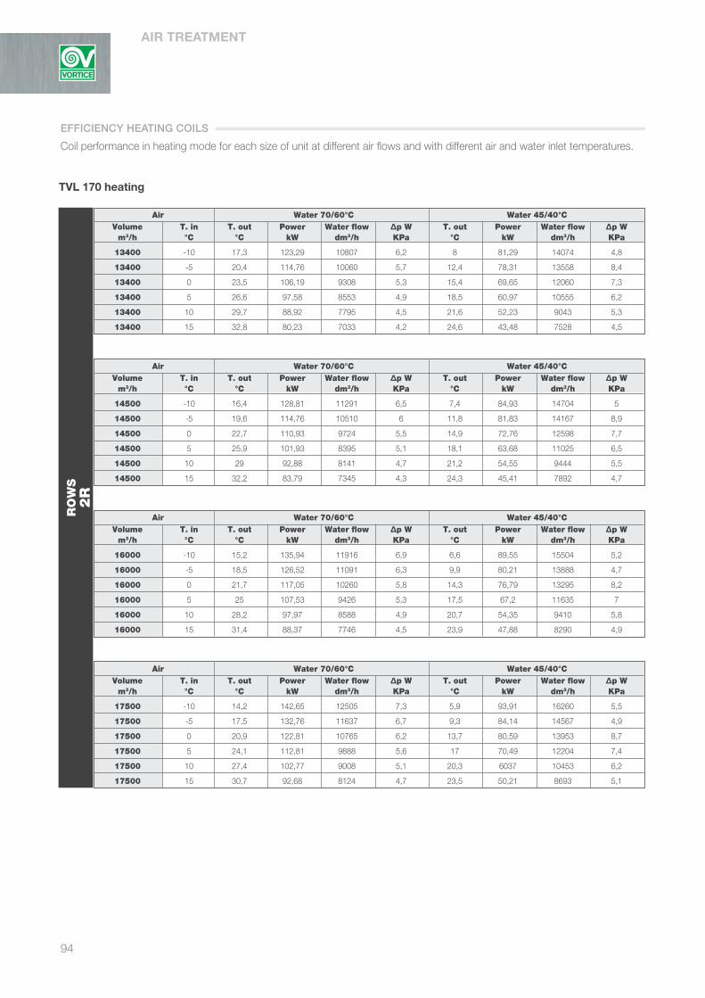
AIR TREATMENT
94
TVL 170 heating
Air Water 70/60°C Water 45/40°C Volume T. in T. out Power Water flow ∆p W T. out Power Water flow ∆p W m3/h °C °C kW dm3/h KPa °C kW dm3/h KPa
13400 -10 17,3 123,29 10807 6,2 8 81,29 14074 4,8
13400 -5 20,4 114,76 10060 5,7 12,4 78,31 13558 8,4
13400 0 23,5 106,19 9308 5,3 15,4 69,65 12060 7,3
13400 5 26,6 97,58 8553 4,9 18,5 60,97 10555 6,2
13400 10 29,7 88,92 7795 4,5 21,6 52,23 9043 5,3
13400 15 32,8 80,23 7033 4,2 24,6 43,48 7528 4,5
Air Water 70/60°C Water 45/40°C Volume T. in T. out Power Water flow ∆p W T. out Power Water flow ∆p W m3/h °C °C kW dm3/h KPa °C kW dm3/h KPa
14500 -10 16,4 128,81 11291 6,5 7,4 84,93 14704 5
14500 -5 19,6 114,76 10510 6 11,8 81,83 14167 8,9
14500 0 22,7 110,93 9724 5,5 14,9 72,76 12598 7,7
14500 5 25,9 101,93 8395 5,1 18,1 63,68 11025 6,5
14500 10 29 92,88 8141 4,7 21,2 54,55 9444 5,5
14500 15 32,2 83,79 7345 4,3 24,3 45,41 7892 4,7
Air Water 70/60°C Water 45/40°C Volume T. in T. out Power Water flow ∆p W T. out Power Water flow ∆p W m3/h °C °C kW dm3/h KPa °C kW dm3/h KPa
16000 -10 15,2 135,94 11916 6,9 6,6 89,55 15504 5,2
16000 -5 18,5 126,52 11091 6,3 9,9 80,21 13888 4,7
16000 0 21,7 117,05 10260 5,8 14,3 76,79 13295 8,2
16000 5 25 107,53 9426 5,3 17,5 67,2 11635 7
16000 10 28,2 97,97 8588 4,9 20,7 54,35 9410 5,8
16000 15 31,4 88,37 7746 4,5 23,9 47,88 8290 4,9
Air Water 70/60°C Water 45/40°C Volume T. in T. out Power Water flow ∆p W T. out Power Water flow ∆p W m3/h °C °C kW dm3/h KPa °C kW dm3/h KPa
17500 -10 14,2 142,65 12505 7,3 5,9 93,91 16260 5,5
17500 -5 17,5 132,76 11637 6,7 9,3 84,14 14567 4,9
17500 0 20,9 122,81 10765 6,2 13,7 80,59 13953 8,7
17500 5 24,1 112,81 9888 5,6 17 70,49 12204 7,4
17500 10 27,4 102,77 9008 5,1 20,3 6037 10453 6,2
17500 15 30,7 92,68 8124 4,7 23,5 50,21 8693 5,1
RO
WS
2R
Coil performance in heating mode for each size of unit at different air flows and with different air and water inlet temperatures.
EFFICIENCY HEATING COILS

95
TVL
TVL 170 heating
Air Water 70/60°C Water 45/40°C Volume T. in T. out Power Water flow ∆p W T. out Power Water flow ∆p W m3/h °C °C kW dm3/h KPa °C kW dm3/h KPa
13400 -10 28,4 173,28 15190 5,5 17 121,87 21100 8,2
13400 -5 30,8 161,28 14137 5,1 19,3 109,81 19013 7,2
13400 0 33,1 149,24 13082 4,8 21,7 97,7 16914 6,3
13400 5 25,4 137,16 12023 4,4 24 85,53 14807 5,5
13400 10 37,7 125,02 10958 4,1 26,3 73,33 12695 4,8
13400 15 40 112,84 9891 3,9 28,6 61,11 10580 4,1
Air Water 70/60°C Water 45/40°C Volume T. in T. out Power Water flow ∆p W T. out Power Water flow ∆p W m3/h °C °C kW dm3/h KPa °C kW dm3/h KPa
14500 -10 27,2 181,63 15920 5,7 16,2 127,78 22123 8,8
14500 -5 29,6 169,05 14818 5,3 18,6 115,12 19932 7,7
14500 0 32 156,41 13711 5 21 102,39 17728 6,7
14500 5 34,4 143,72 12599 4,6 23,4 89,63 15518 5,8
14500 10 36,8 130,99 11483 4,3 25,7 76,83 13302 5
14500 15 39,2 118,22 10363 4 28,1 64,01 11082 4,3
Air Water 70/60°C Water 45/40°C Volume T. in T. out Power Water flow ∆p W T. out Power Water flow ∆p W m3/h °C °C kW dm3/h KPa °C kW dm3/h KPa
16000 -10 25,7 192,43 16897 6,1 15,1 135,4 23442 9,5
16000 -5 28,2 179,07 15696 5,6 17,6 121,99 21120 8,3
16000 0 30,8 165,67 14522 5,2 20,1 108,49 18784 7,1
16000 5 33,3 152,21 13342 4,8 22,6 94,96 16440 6,1
16000 10 35,8 138,71 12159 4,5 25,1 81,37 14088 5,2
16000 15 38,2 125315 10970 4,1 27,6 67,77 11733 4,5
Air Water 70/60°C Water 45/40°C Volume T. in T. out Power Water flow ∆p W T. out Power Water flow ∆p W m3/h °C °C kW dm3/h KPa °C kW dm3/h KPa
17500 -10 24,4 202,62 17761 6,5 14,2 142,63 24694 10,3
17500 -5 27 188,54 16527 6 16,8 128,49 22247 8,8
17500 0 29,6 174,41 15288 5,5 19,4 114,25 19781 7,6
17500 5 32,2 160,22 14044 5,1 22 99,98 17309 6,5
17500 10 34,8 145,98 12796 4,7 24,5 85,65 14830 5,5
17500 15 37,4 131,7 11544 4,3 27,1 71,31 12346 4,6
RO
WS
3R
TVL
EFFICIENCY HEATING COILS

AIR TREATMENT
96
TVL 170 heating
Air Water 70/60°C Water 45/40°C Volume T. in T. out Power Water flow ∆p W T. out Power Water flow ∆p W m3/h °C °C kW dm3/h KPa °C kW dm3/h KPa
13400 -10 37,9 215,96 18930 20,2 - - - -
13400 -5 39,7 201,52 17665 17,8 25,3 136,45 23625 32,4
13400 0 41,5 187,03 16394 15,5 27 121,88 21102 26,3
13400 5 43,2 172,48 15119 13,3 28,8 107,26 18570 20,7
13400 10 45 157,87 13839 11,3 30,5 92,6 16033 15,8
13400 15 46,7 143,21 12554 9,5 32,3 77,89 13485 11,5
Air Water 70/60°C Water 45/40°C Volume T. in T. out Power Water flow ∆p W T. out Power Water flow ∆p W m3/h °C °C kW dm3/h KPa °C kW dm3/h KPa
14500 -10 36,5 2227,11 19908 22,2 - - - -
14500 -5 38,4 211,88 18573 19,5 - - - -
14500 0 40,3 196,59 17232 17 26,3 128,17 22191 28,9
14500 5 42,1 181,29 15891 14,6 28,1 112,83 19536 22,8
14500 10 44 165,93 14545 12,4 29,9 97,68 16860 17,3
14500 15 45,8 150,45 13188 10,3 31,8 81,91 14182 12,6
Air Water 70/60°C Water 45/40°C Volume T. in T. out Power Water flow ∆p W T. out Power Water flow ∆p W m3/h °C °C kW dm3/h KPa °C kW dm3/h KPa
16000 -10 34,8 241,53 21172 24,9 - - - -
16000 -5 36,8 225,37 19756 21,9 - - - -
16000 0 38,8 209,05 18324 19 25,3 136,33 23604 32,4
16000 5 40,8 192,76 16897 16,4 27,3 120,03 20782 25,5
16000 10 42,8 176,42 15464 13,9 29,2 103,55 17927 19,4
16000 15 44,7 160 14026 11,6 31,2 87,07 15075 14,1
Air Water 70/60°C Water 45/40°C Volume T. in T. out Power Water flow ∆p W T. out Power Water flow ∆p W m3/h °C °C kW dm3/h KPa °C kW dm3/h KPa
17500 -10 33,3 255,17 22367 27,6 - - - -
17500 -5 35,4 238,04 20865 24,2 - - - -
17500 0 37,5 220,93 19366 21,1 - - - -
17500 5 39,6 203,66 17852 18,1 26,5 126,76 21946 28,3
17500 10 41,6 186,31 16331 15,4 28,6 109,38 18936 21,5
17500 15 43,7 168,96 14810 12,8 30,6 91,99 15927 15,6
RO
WS
4R
- Contact our Technical/Sales Department
EFFICIENCY HEATING COILS

97
TVL
TVL 170 cooling
Air Water 7/12°C Water 8/13°C Volume T. in T. out Power Water flow ∆p W T. out Power Water flow ∆p W m3/h °C °C kW dm3/h KPa °C kW dm3/h KPa
13400 22 / 50% - - - - - - - -
13400 24 / 50% 15,9 37,88 6511 5,1 - - - -
13400 26 / 50% 16,7 46,19 7939 6,3 17,3 41,86 7194 5,6
13400 28 / 50% 17,6 55,7 9573 7,8 18,2 50,82 8734 6,9
13400 32 / 50% 21 92 15822 17,5 20,1 74,93 12877 6,6
13400 35 / 50% 21,3 103,95 17867 22 21,7 97,48 16754 19,4
Air Water 7/12°C Water 8/13°C Volume T. in T. out Power Water flow ∆p W T. out Power Water flow ∆p W m3/h °C °C kW dm3/h KPa °C kW dm3/h KPa
14500 22 / 50% - - - - - - - -
14500 24 / 50% 16,1 39,69 6821 5,4 - - - -
14500 26 / 50% 16,9 48,29 8300 6,6 17,5 43,81 7529 5,9
14500 28 / 50% 17,9 58,29 10011 8,2 18,4 53,16 9136 7,3
14500 32 / 50% 19,9 84,51 14525 15 20,4 78 13406 12,9
14500 35 / 50% 21,6 108,3 18613 23,7 22 101,54 17450 20,9
Air Water 7/12°C Water 8/13°C Volume T. in T. out Power Water flow ∆p W T. out Power Water flow ∆p W m3/h °C °C kW dm3/h KPa °C kW dm3/h KPa
16000 22 / 50% - - - - - - - -
16000 24 / 50% 16,3 42,09 7233 5,7 - - - -
16000 26 / 50% 17,2 50,94 8756 7 17,8 46,33 7962 6,3
16000 28 / 50% 18,3 60,7 10433 8,6 18,7 56,12 9645 7,8
16000 32 / 50% 20,3 88,84 15269 16,5 20,7 81,95 14083 14,1
16000 35 / 50% 22 113,95 19586 26 22,4 106,75 18346 23
Air Water 7/12°C Water 8/13°C Volume T. in T. out Power Water flow ∆p W T. out Power Water flow ∆p W m3/h °C °C kW dm3/h KPa °C kW dm3/h KPa
17500 22 / 50% - - - - - - - -
17500 24 / 50% 16,7 43,6 7494 5,9 - - - -
17500 26 / 50% 17,6 52,75 9067 7,3 18,1 48,7 8369 6,6
17500 28 / 50% 18,6 63,75 10957 9,2 19 58,83 10110 8,3
17500 32 / 50% 20,6 92,93 15973 17,9 21,2 84,42 14508 14,9
17500 35 / 50% 22,4 119,2 20487 28,3 22,8 111,67 19192 24,9
RO
WS
4R
- Contact our Technical/Sales Department
Coil performance in cooling mode for each size of unit at different air flows and with different air and water inlet temperatures.
TVL
EFFICIENCY COOLING COILS

AIR TREATMENT
98
TVL 170 cooling
Air Water 7/12°C Water 8/13°C Volume T. in T. out Power Water flow ∆p W T. out Power Water flow ∆p W m3/h °C °C kW dm3/h KPa °C kW dm3/h KPa
13400 22 / 50% 12,9 42,34 7276 6,8 13,6 38,41 6601 6,1
13400 24 / 50% 13,5 51,56 8862 8,6 14,1 46,98 8075 7,7
13400 26 / 50% 14,3 62,9 10811 11,7 14,8 57,34 9855 9,8
13400 28 / 50% 15 76,69 13181 16,8 15,6 69,95 12022 14,1
13400 32 / 50% 16,5 110,42 18978 32,5 17,1 102,69 17648 28,3
13400 35 / 50% 17,8 139,75 24019 50 18,4 131,71 22636 44,6
Air Water 7/12°C Water 8/13°C Volume T. in T. out Power Water flow ∆p W T. out Power Water flow ∆p W m3/h °C °C kW dm3/h KPa °C kW dm3/h KPa
14500 22 / 50% 13,1 44,54 7655 7,2 13,8 40,43 6948 6,4
14500 24 / 50% 13,7 54,27 9328 9,2 14,3 49,41 8491 8,1
14500 26 / 50% 14,5 65,98 1341 12,8 15,1 60,1 10329 10,7
14500 28 / 50% 15,3 80,13 13772 18,1 15,9 73,24 12586 15,3
14500 32 / 50% 16,9 115,56 19861 35,5 17,4 107,38 18454 30,7
14500 35 / 50% 18,2 146,39 25161 54,4 18,7 137,74 23672 48,4
Air Water 7/12°C Water 8/13°C Volume T. in T. out Power Water flow ∆p W T. out Power Water flow ∆p W m3/h °C °C kW dm3/h KPa °C kW dm3/h KPa
16000 22 / 50% 13,4 47,33 8134 7,8 14,1 43007 7402 6,9
16000 24 / 50% 14 57,51 9887 10 14,7 52,33 8933 8,7
16000 26 / 50% 14,8 69,65 11971 14,1 15,4 63,86 10975 12
16000 28 / 50% 15,7 84,35 14497 19,9 16,2 77,45 13311 17
16000 32 / 50% 17,3 122,09 20985 39 17,9 113,32 19475 33,9
16000 35 / 50% 18,7 154,6 26571 60 19,2 145,65 250,31 53,6
Air Water 7/12°C Water 8/13°C Volume T. in T. out Power Water flow ∆p W T. out Power Water flow ∆p W m3/h °C °C kW dm3/h KPa °C kW dm3/h KPa
17500 22 / 50% 13,7 49,94 8584 8,3 14,4 45,56 7830 7,4
17500 24 / 50% 14,3 60,72 10437 11 14,9 55,38 9518 9,4
17500 26 / 50% 15,1 73,48 12629 15,5 15,6 67,18 11546 13,1
17500 28 / 50% 16 88,73 15250 21,8 17,5 71,78 12336 6,6
17500 32 / 50% 17,7 128,22 22037 42,7 16,5 81,4 13989 18,6
17500 35 / 50% 19,1 162,57 27941 65,9 19,6 152,9 26277 58,6
RO
WS
6R
EFFICIENCY COOLING COILS

99
TVL
TVL 250 heating
Air Water 70/60°C Water 45/40°C Volume T. in T. out Power Water flow ∆p W T. out Power Water flow ∆p W m3/h °C °C kW dm3/h KPa °C kW dm3/h KPa
19100 -10 17,6 177,7 15577 9,6 9,5 125,14 21667 18,5
19100 -5 20,7 165,52 14509 8,7 12,6 112,84 19536 15,2
19100 0 23,8 153,26 13434 7,8 15,6 100,47 17395 12,2
19100 5 26,9 140,96 12356 7,1 18,7 88,05 15244 9,6
19100 10 30 128,6 11273 6,3 21,8 75,57 13084 7,8
19100 15 33,1 116,17 10183 5,7 24,8 63,06 10918 6,3
Air Water 70/60°C Water 45/40°C Volume T. in T. out Power Water flow ∆p W T. out Power Water flow ∆p W m3/h °C °C kW dm3/h KPa °C kW dm3/h KPa
20800 -10 16,6 186,33 16332 10,3 8,7 131,27 22727 20,3
20800 -5 19,8 173,54 15212 9,2 11,9 118,37 20489 16,7
20800 0 22,9 160,71 14087 8,3 15,1 105,36 18241 13,4
20800 5 26,1 147,79 12955 7,5 18,2 92,32 15983 10,4
20800 10 29,3 134,8 11817 6,7 21,3 79,23 13717 8,3
20800 15 324 121,76 10673 6 24,4 66,09 11443 6,7
Air Water 70/60°C Water 45/40°C Volume T. in T. out Power Water flow ∆p W T. out Power Water flow ∆p W m3/h °C °C kW dm3/h KPa °C kW dm3/h KPa
22800 -10 15,5 195,95 17176 11,4 8 138,06 23904 22,3
22800 -5 18,8 182,5 15997 9,9 11,2 124,46 21549 18,4
22800 0 22 168,97 14811 8,9 14,4 110,8 19183 14,7
22800 5 25,2 155,37 13620 8 17,6 97,07 16806 11,5
22800 10 28,5 141,72 12423 7,1 20,9 83,29 14420 8,9
22800 15 31,7 127,98 11218 6,6 24,1 69,47 12027 7,1
Air Water 70/60°C Water 45/40°C Volume T. in T. out Power Water flow ∆p W T. out Power Water flow ∆p W m3/h °C °C kW dm3/h KPa °C kW dm3/h KPa
25000 -10 14,5 205,94 18052 12,5 7,2 145,13 25127 24,6
25000 -5 17,8 191,77 16810 10,9 10,5 130,81 22648 20,2
25000 0 21,1 177,55 15564 9,5 13,8 116,44 20160 16,2
25000 5 24,4 163,25 14310 8,5 17,1 101,99 17658 12,6
25000 10 27,7 148,87 13049 7,6 20,4 87,51 15150 9,5
25000 15 31 134,42 11783 6,7 23,7 72,96 12631 7,5
RO
WS
2R
Coil performance in heating mode for each size of unit at different air flows and with different air and water inlet temperatures.
TVL
EFFICIENCY HEATING COILS

AIR TREATMENT
100
TVL 250 heating
Air Water 70/60°C Water 45/40°C Volume T. in T. out Power Water flow ∆p W T. out Power Water flow ∆p W m3/h °C °C kW dm3/h KPa °C kW dm3/h KPa
19100 -10 28,8 249,88 21886 8 17,3 175,42 30371 14,4
19100 -5 31,2 232,55 20384 7,3 19,6 158,19 27388 11,9
19100 0 33,5 215,35 18877 6,7 21,9 140,87 24389 9,6
19100 5 35,8 198,08 17363 6,1 24,2 123,49 21379 8,1
19100 10 38,1 180,74 15843 5,5 26,5 106,5 18361 6,7
19100 15 40,4 163,33 14317 5 28,8 88,58 15335 5,5
Air Water 70/60°C Water 45/40°C Volume T. in T. out Power Water flow ∆p W T. out Power Water flow ∆p W m3/h °C °C kW dm3/h KPa °C kW dm3/h KPa
20800 -10 27,5 262,76 23033 8,6 16,4 184,64 31968 15,9
20800 -5 29,9 244,7 21450 7,8 18,8 166,5 28826 13,1
20800 0 32,4 226,56 19860 7,1 21,3 148,25 25666 10,5
20800 5 34,8 208,39 18267 6,4 23,6 129,93 22496 8,6
20800 10 37,1 190,11 16664 5,8 25,9 111,57 19317 7,1
20800 15 39,5 171,8 15059 5,3 28,3 93,16 16129 5,8
Air Water 70/60°C Water 45/40°C Volume T. in T. out Power Water flow ∆p W T. out Power Water flow ∆p W m3/h °C °C kW dm3/h KPa °C kW dm3/h KPa
22800 -10 26,1 277,31 24308 9,2 15,4 194,91 33745 17,6
22800 -5 28,6 258,25 22637 8,4 17,9 175,77 30431 14,5
22800 0 31,1 239,1 20959 7,6 20,4 156,48 27092 11,6
22800 5 33,6 219,88 19274 6,9 22,9 137,13 23742 9,3
22800 10 36,1 200,58 17582 6,2 25,3 117,72 20382 7,6
22800 15 38,6 181,21 15884 5,5 27,8 98,26 17,012 6,1
Air Water 70/60°C Water 45/40°C Volume T. in T. out Power Water flow ∆p W T. out Power Water flow ∆p W m3/h °C °C kW dm3/h KPa °C kW dm3/h KPa
25000 -10 24,7 292,47 25637 10 14,4 205,63 35601 19,5
25000 -5 27,4 272,32 23870 9 17 185,42 32102 16
25000 0 30 252,12 22100 8,1 19,6 165,5 28575 12,9
25000 5 32,5 231,83 20322 7,3 22,2 144,61 25037 10
25000 10 35,1 211,44 18534 6,5 24,8 124,12 21489 8,1
25000 15 37,7 191 16743 5,8 27,3 103,57 17932 6,5
RO
WS
3R
EFFICIENCY HEATING COILS

101
TVL
TVL 250 heating
Air Water 70/60°C Water 45/40°C Volume T. in T. out Power Water flow ∆p W T. out Power Water flow ∆p W m3/h °C °C kW dm3/h KPa °C kW dm3/h KPa
19100 -10 38,1 309,64 27141 36,5 - - - -
19100 -5 39,9 289,01 25333 32,1 - - - -
19100 0 41,7 268,29 23517 27,9 - - - -
19100 5 43,5 247,5 21694 24 29 154,06 26674 37,3
19100 10 45,3 226,7 19871 20,3 30,7 133,12 23048 28,4
19100 15 47 205,83 18042 17 32,4 112,11 19410 20,6
Air Water 70/60°C Water 45/40°C Volume T. in T. out Power Water flow ∆p W T. out Power Water flow ∆p W m3/h °C °C kW dm3/h KPa °C kW dm3/h KPa
20800 -10 36,7 326,9 28656 40,4 - - - -
20800 -5 38,6 305,17 26750 35,5 - - - -
20800 0 40,5 283,36 24839 30,9 - - - -
20800 5 42,3 261,33 22907 26,6 28,2 162,59 28149 41,3
20800 10 44,2 239,26 20982 22,5 30,1 140,52 24329 31,4
20800 15 46 217,12 19032 18,8 31,9 118,24 20470 22,8
Air Water 70/60°C Water 45/40°C Volume T. in T. out Power Water flow ∆p W T. out Power Water flow ∆p W m3/h °C °C kW dm3/h KPa °C kW dm3/h KPa
22800 -10 - - - - - - - -
22800 -5 37,1 323,23 28333 39,6 - - - -
22800 0 39,1 300,4 26300 34,4 - - - -
22800 5 41 276,75 24259 29,6 - - - -
22800 10 43 253,37 22209 25,1 29,4 148,84 25770 35
22800 15 44,9 229,88 20150 20,9 31,3 125,29 21693 25,4
Air Water 70/60°C Water 45/40°C Volume T. in T. out Power Water flow ∆p W T. out Power Water flow ∆p W m3/h °C °C kW dm3/h KPa °C kW dm3/h KPa
25000 -10 - - - - - - - -
25000 -5 - - - - - - - -
25000 0 37,7 317,48 27829 38,3 - - - -
25000 5 39,8 292,88 25673 32,9 - - - -
25000 10 41,8 268 23493 27,8 28,7 157,43 27256 38,9
25000 15 43,9 243,23 21320 23,2 30,8 132,52 22944 28,2
RO
WS
4R
- Contact our Technical/Sales Department
TVL
EFFICIENCY HEATING COILS

AIR TREATMENT
102
TVL 250 cooling
Air Water 7/12°C Water 8/13°C Volume T. in T. out Power Water flow ∆p W T. out Power Water flow ∆p W m3/h °C °C kW dm3/h KPa °C kW dm3/h KPa
19100 22 / 50% 15 45,67 7850 5,8 15,7 41,47 7128 5,3
19100 24 / 50% 15,7 55,59 9554 7,3 16,3 50,15 8620 6,4
19100 26 / 50% 16,6 67,4 11585 9,2 17,1 61,08 10497 8,1
19100 28 / 50% 17,5 81,29 13971 12,7 18 74,16 12745 10,7
19100 32 / 50% 19,5 117,93 20268 25,3 20 109,7 18744 21,8
19100 35 / 50% 21,1 150,51 25868 39,6 21,6 141,35 24292 35,1
Air Water 7/12°C Water 8/13°C Volume T. in T. out Power Water flow ∆p W T. out Power Water flow ∆p W m3/h °C °C kW dm3/h KPa °C kW dm3/h KPa
20800 22 / 50% 15,2 48,09 8265 6,2 15,9 43,67 7506 5,6
20800 24 / 50% 15,9 58,3 10020 7,7 16,6 52,82 9078 6,8
20800 26 / 50% 16,8 70,86 12179 9,9 17,4 64,25 11043 8,7
20800 28 / 50% 17,8 85,22 14648 13,9 18,3 77,84 13372 11,7
20800 32 / 50% 19,9 123,26 21185 27,4 20,3 114 19591 23,6
20800 35 / 50% 21,5 157,45 27062 43,1 21,9 147,8 25401 38,2
Air Water 7/12°C Water 8/13°C Volume T. in T. out Power Water flow ∆p W T. out Power Water flow ∆p W m3/h °C °C kW dm3/h KPa °C kW dm3/h KPa
22800 22 / 50% 15,5 50,79 8730 6,5 16,1 46,15 7931 5,9
22800 24 / 50% 16,2 61,51 10572 8,2 16,9 5,81 9591 7,3
22800 26 / 50% 17,1 74,52 12809 10,9 17,6 67,68 1163 29,3
22800 28 / 50% 18,1 89,71 15419 15,3 18,6 81,92 14079 12,9
22800 32 / 50% 202 129,2 22205 29,9 20,6 119,35 20511 25,7
22800 35 / 50% 21,9 165,07 28371 47 22,3 154,86 26614 41,6
Air Water 7/12°C Water 8/13°C Volume T. in T. out Power Water flow ∆p W T. out Power Water flow ∆p W m3/h °C °C kW dm3/h KPa °C kW dm3/h KPa
25000 22 / 50% 15,7 53,6 9212 7 16,3 48,68 8367 6,2
25000 24 / 50% 16,4 64,89 11152 8,8 17,1 58,89 10121 7,8
25000 26 / 50% 17,4 78,37 13470 11,9 17,9 71,26 12247 9,9
25000 28 / 50% 18,5 92,99 15982 16,3 18,9 86,2 14815 14,1
25000 32 / 50% 20,5 135,23 23243 32,5 21,1 122,98 21136 27,2
25000 35 / 50% 22,3 172,96 29729 51,3 22,7 162,17 27870 45,3
RO
WS
4R
EFFICIENCY COOLING COILS

103
TVL
TVL 250 cooling
Air Water 7/12°C Water 8/13°C Volume T. in T. out Power Water flow ∆p W T. out Power Water flow ∆p W m3/h °C °C kW dm3/h KPa °C kW dm3/h KPa
19100 22 / 50% 13,2 57,63 9905 4,8 14 51,98 8933 4,4
19100 24 / 50% 13,8 70,78 12165 5,8 14,4 64,17 11029 5,2
19100 26 / 50% 14,5 86,17 14810 7,2 15,1 78,59 13506 6,4
19100 28 / 50% 15,3 105,07 18059 9,2 15,9 96 16499 8,1
19100 32 / 50% 16,8 152,33 26180 17,6 17,4 141,28 24280 15,3
19100 35 / 50% 18,1 193,77 33304 27,5 18,6 182,22 31317 24,4
Air Water 7/12°C Water 8/13°C Volume T. in T. out Power Water flow ∆p W T. out Power Water flow ∆p W m3/h °C °C kW dm3/h KPa °C kW dm3/h KPa
20800 22 / 50% 13,4 60,87 10462 5 14,2 55,19 9485 4,6
20800 24 / 50% 14 74,63 12828 6,1 14,7 67,78 11648 5,5
20800 26 / 50% 14,8 90,48 15551 7,6 15,3 82,64 14203 6,8
20800 28 / 50% 15,6 109,92 18892 9,7 16,1 100,69 17304 8,7
20800 32 / 50% 17,6 159,78 27461 19,3 17,7 148,06 25446 16,7
20800 5 / 50% 18,5 203,38 34956 30 19 191,24 32867 26,7
Air Water 7/12°C Water 8/13°C Volume T. in T. out Power Water flow ∆p W T. out Power Water flow ∆p W m3/h °C °C kW dm3/h KPa °C kW dm3/h KPa
22800 22 / 50% 13,7 64,65 11111 5,3 14,5 58,77 10101 4,8
22800 24 / 50% 14,3 78,86 13554 6,5 14,9 71,81 12341 5,8
22800 26 / 50% 15,1 95,64 16437 8,1 15,6 87,04 14959 7,2
22800 28 / 50% 15,9 115,8 19903 10,7 16,4 105,99 18215 9,2
22800 32 / 50% 17,6 168,1 28892 21,1 18,1 155,66 26751 18,3
22800 35 / 50% 18,9 214,04 36787 33 19,5 201,31 34596 29,3
Air Water 7/12°C Water 8/13°C Volume T. in T. out Power Water flow ∆p W T. out Power Water flow ∆p W m3/h °C °C kW dm3/h KPa °C kW dm3/h KPa
25000 22 / 50% 14 65,88 11783 5,6 14,7 62,32 10711 5,1
25000 24 / 50% 14,6 83,42 14337 6,9 15,2 76,01 13064 6,2
25000 26 / 50% 15,4 100,86 17335 8,7 15,9 91,99 15810 7,7
25000 28 / 50% 16,2 121,92 20954 11,7 16,7 111,79 19211 10
25000 32 / 50% 17,9 176,74 30377 23,2 18,5 162,24 27883 19,7
25000 35 / 50% 19,4 225,1 38688 36,2 19,9 211,55 36357 32,2
RO
WS
6R
TVL
EFFICIENCY COOLING COILS

Coils
m3/h V = m/s 2R 3R 4R 6R Panel filters Damper Grill
1700 2 15,9 23 30,8 39,7 80 30 21
2200 2,5 23,5 32,7 46,3 58,4 96 50 49
2400 2,75 26,9 37,2 53,1 66,6 104 55 88
2600 3 30,5 43,2 60,3 75,1 104 65 90
2300 2 15,4 21,4 30,6 60 72 30 21
2900 2,5 22,1 30,8 67,7 84,3 84 45 49
3200 2,75 24,5 36 82,4 98 92 55 68
3500 3 28,3 43,7 94,3 112 96 65 90
2900 2 15,4 22,6 49,9 62,5 64 30 21
3600 2,5 21,7 30,1 66 82 76 45 49
4000 2,75 25 37,3 80,9 100,7 80 55 68
4300 3 28,6 41,7 90,2 107 84 60 90
5000 2,3 20,7 30,3 66,2 82,5 80 25 21
5400 2,5 23,4 34,1 74,3 92,5 84 30 35
5900 2,75 26,9 39,2 84,9 105,5 88 35 49
6500 3 31,3 45,6 90,4 121,8 96 40 68
7000 2,3 20,7 30,3 66,2 82,5 76 30 21
7600 2,5 23,4 34,4 74,9 93,2 80 35 35
8300 2,75 26,9 39,5 85,5 106,3 84 40 49
9100 3 31,3 45,6 98,2 121,8 92 50 68
8700 2,3 20,5 30 65,6 81,8 80 25 21
9500 2,5 23,6 34,4 74,9 93,3 84 25 49
10400 2,75 27,2 39,6 85,8 106,7 88 30 49
11300 3 30,9 45,1 97,2 120,7 92 40 88
10400 2,3 20,4 29,8 65,2 81,4 80 2,77 35
11300 2,5 23,3 33,9 73,9 92 84 3,01 49
12400 2,75 26,9 39,2 85 105,6 88 3,30 49
13600 3 31,1 43,5 97,6 121,2 96 3,62 88
13400 2,3 20,5 29,9 65,4 81,6 84 30 35
14500 2,5 23,3 33,8 73,7 91,8 88 35 49
16000 2,75 27 39,4 85,4 106,2 92 40 68
17000 3 31,1 45,4 97,8 121,3 100 50 88
19100 2,3 20,5 29,9 65,4 81,6 84 25 35
20800 2,5 23,4 34,1 74,4 92,6 92 30 49
22800 2,75 27 39,4 85,4 106,1 96 40 68
25000 3 31,2 45,5 98 121,6 104 45 90
AIR TREATMENT
104
TVL
20
TVL
30
TVL
40
TVL
60
TVL
80
TVL
100
TVL
120
TVL
170
TVL
25
0
NOTE: The 4-row coils show the pressure drop on the cooling side.
PRESSURE DROP

105
TVL
velocità < = 2 m/s
velocità max 2,5 m/s
1500
Portata d’aria / Air flow [m³/h]
ModelloModel
TVL 20
TVL 30
TVL 40
TVL 60
TVL 80
TVL 100
TVL 120
TVL 170
TVL 250
0400800
1200160020002400280032003600400044004800520056006000640068007200760080008400880092009600
100001040010800112001160012000124001280013200136001400014400148001520015600160001640016800172001760018000184001880019200196002000020400208002120021600220002240022800232002360024000244002480025200256002600026400
TVL 20 TVL 30 TVL 40 TVL 60 TVL 80 TVL 100 TVL 120 TVL 170 TVL 250
TVL
TVL SELECTION

AIR TREATMENT
106
Single speed motor
0
100
200
300
400
500
600
0,55 kW
0,75 kW
1,1 kW
1,5 kW
2,2 kW
3,0 kW
4,0 kW
5,5 kW
7,5 kW
1500
2000
2500
3000
3500
4000
4500
5000
5500
6000
6500
7000
7500
8000
8500
9000
9500
1000
010
500
1100
011
500
1200
012
500
1300
0
1350
0
1400
014
500
1500
0
1550
016
000
1650
017
000
1750
019
000
2050
0
2200
023
500
2500
0
Prev
alen
za s
tatic
a to
tale
/ To
tal s
tatic
pre
ssur
e [
Pa]
Portata d’aria / Air flow [m³/h]
0
100
200
300
400
500
600
0,55 kW
0,75 kW
1,1 kW
1,5 kW
2,2 kW
3,0 kW
4,0 kW
5,5 kW
7,5 kW
1500
2000
2500
3000
3500
4000
4500
5000
5500
6000
6500
7000
7500
8000
8500
9000
9500
1000
010
500
1100
011
500
1200
012
500
1300
0
1350
0
1400
014
500
1500
0
1550
016
000
1650
017
000
1750
019
000
2050
0
2200
023
500
2500
0
Tota
l sta
tic p
ress
ure
[Pa
]
Air flow [m³/h]
TVL SELECTION
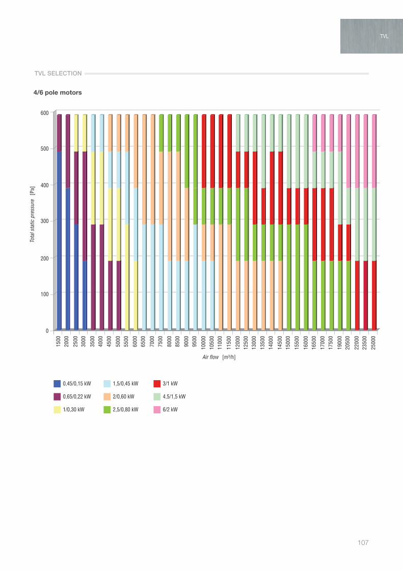
107
TVL
4/6 pole motors
0
100
200
300
400
500
600
0,45/0,15 kW
0,65/0,22 kW
1/0,30 kW
1,5/0,45 kW
2/0,60 kW
2,5/0,80 kW
3/1 kW
4,5/1,5 kW
6/2 kW
Tota
l sta
tic p
ress
ure
[Pa
]
1500
2000
2500
3000
3500
4000
4500
5000
5500
6000
6500
7000
7500
8000
8500
9000
9500
1000
0
1050
011
000
1150
0
1200
012
500
1300
0
1350
0
1400
0
1450
015
000
1550
0
1600
016
500
1700
017
500
1900
020
500
2200
023
500
2500
0
Air flow [m³/h]
TVL
TVL SELECTION

Air flow rate [m3/h]
INDICATE CONFIGURATION:
Fitting side:
Inspection side:
COMPONENTS and ACCESSORIES:
BASIC UNIT
[FI] Pleated synthetic filter
[BAC] Heating coil
[BAF] Cooling coil
ASP [Pa]
Intake:
Outlet:
Rows
Rows
[GR] Intake grill
[SR] Control damper
[PA] Intake plenum
[SM] Mixing chamber with 2 dampers
[PM] Outlet plenum
[MS] Safety microswitch
[VB] Variable pitch pulleys
[TPV] Rain cover for vert. Unit
[TPH] Rain cover for horiz. Unit
[XXX] Extra soundproofing
[PR] Differential pressure switch
[MA] Water column differential pressure gauge
[VB] Variable pitch pulley
[CM] Manual damper control
TOTAL STATIC PRESSURE: Pa
MOTOR kW - N° Poles
TOTAL PRICE LIST: v
Pressure drop [Pa]
Price List [v]
R L
R L
YES NO
YES NO
YES NO
YES NO
YES NO
YES NO
YES NO
YES NO
YES NO
YES NO
YES NO
YES NO
YES NO
[number of items]
H1 H2 H3 V1 V2 V3
R1 R2 R3
M1 M2 M3
AIR TREATMENT
108
SAMPLE UNIT SELECTION
TVL Quotation Table

109
TVL
TVL

AIR TREATMENT
110
TVL-DDDirectly coupled thermoventilating units horizontaland vertical execution + accessories
PRODUCT SPECIFICATIONS
The TVL-DD fan coils stand out for their operating versatility in different environments. They feature compact dimensions, with excellent air flow and thermal performance and low noise.
Ideal for small or medium-sized environments such as: offices, agencies, homes and shops, offering extremely simple installation even in restricted spaces.
This series uses centrifugal fans directly coupled to single-phase three-speed motors, covering a range of flow-rates from 1000 m3/h to 4000 m3/h.
Frame, made using a modular system of extruded anodised aluminium alloy section bars (in accordance with UNI 9006/1), joined by die-cast aluminium corners, sandwich panels, insulated using polyurethane foam, density 40 kg/m3, 23 mm thick.
Outside panel made from coated sheet metal, 6/10 thickness, inside panel made from galvanised sheet metal, 6/10 thickness.
G4 filter, synthetic filtering media, weighted average efficiency ≥ 90% with galvanised frame and retaining mesh.
Heat exchange coils suitable for cooling and heating operation (according to the number of rows R installed) made from 5/8” copper tube with aluminium fins and turbulators.
Electric coils with finned tubular air heaters, one or more stages. Condensate collection basin made from galvanised sheet
metal complete with front drain and welded hose fitting. Double suction centrifugal fans with forward curved
blades, complete with 4-pole, external rotor motor.
Warning: Maximum operating temperature between -20°C and +40°C.
KEY FEATURES

111
MODEL TVL-DD 10 15 20 30 40Air flow rate (maximum speed) m3/h 1000 1500 2000 3000 4000Static pressure (1) Pa 230 365 340 365 340Sound pressure level (2) dB(A) 59 62 64 62 64
FAN TVL-DD 10 15 20 30 40Power imput W 184 350 350 2x350 2x350Max absorbed current A 1,7 3,1 3 2x3,1 2x3N. of fans n° 1 1 1 2 2Fan speeds n° 3 3 3 3 3Poles n° 4 4 4 4 4Enclosure protection IP 55 55 55 55 55Insulation class B F F F FElectrical supply V / ph / Hz 230 / 1 / 50
FILTER TVL-DD 10 15 20 30 40Efficiency G4 G4 G4 G4 G4Crossing speed m/s 1,11 1,67 2,22 2,08 2,22Average pressure drop Pa 25 45 60 55 60
2R hot water coil TVL-DD 10 15 20 30 40Heating capacity (3) kW 8,1 10,3 12,2 17,4 27,8Supply air temperature °C 35,9 32,5 30 29,2 32,6Water flow dm3/h 707 906 1069 1520 2451Water pressure drop kPa 1,6 2,6 3,5 2,8 7,6Air pressure drop Pa 8 14 21 24 26Connection diameter Gas 3/4” 3/4” 3/4” 3/4” 3/4”
4R hot water coil TVL-DD 10 15 20 30 40Heating capacity (3) kW 14,8 20 24,5 35,6 55Supply air temperature °C 55,9 51,6 48,4 47,2 52,8Water flow dm3/h 1296 1755 2147 3120 4848Water pressure drop kPa 3,5 6,1 9 9 5,7Air pressure drop Pa 15 28 42 49 53Connection diameter Gas 3/4” 3/4” 3/4” 3/4” 1”
4R cold water coil TVL-DD 10 15 20 30 40Total cooling capacity (4) kW 8,6 11,6 13,3 19,1 23,4Supply air temperature °C 15,9 17,4 18,7 19,1 19,6Sensible cooling capacity kW 5,1 6,96 9,31 13,3 16,3Water flow dm3/h 1485 1995 2287 3288 4015Water pressure drop kPa 2,2 8,8 11,3 11,6 4,7Air pressure drop Pa 28 52 70 81 88Connection diameter Gas 3/4” 3/4” 3/4” 3/4” 1”
6R cold water coil TVL-DD 10 15 20 30 40Total cooling capacity (4) kW 10,8 14,2 17 24,8 30Supply air temperature °C 13,6 15,2 16,2 16,5 17,3Sensible cooling capacity kW 6,48 8,5 10,2 14,88 21Water flow dm3/h 1861 2438 2926 4263 5155Water pressure drop kPa 5,2 8,5 11,9 16,1 5,6Air pressure drop Pa 43 73 112 130 140Connection diameter Gas 1” 1” 1” 1” 1” 1/4
Electric coil TVL-DD 10 15 20 30 40Heating capacity (4) kW 5 7,5 10 15 20Air pressure drop Pa 6,48 8,5 10,2 14,88 21Stages n° 1 1 2 2 2Power consumption A 8,5 12,8 13,6 25,5 34Electrical supply V / ph / Hz 400/ 3 / 50
(1) Referred to the fan: deduct the pressure drop of the selected components in order to get the external static pressure.(2) Sound pressure level: data referred ti 1,5 metres from inlet in free field. The actual operation noise level generally differs from the values shown in the table, depending
on operating conditions, reflected noise and surrounding noise.(3) Inlet air temperature 12°C, UR 0%, water temp. in/out 70/60°C. Air flow at max speed.(4) Inlet air temperature 32°C, UR 50%, water temp. in/out 7/12°C. Air flow at max speed.WARNING - The fans are not suitable for operation at temperatures above 40°C
TVL-DD
TECHNICAL DATA
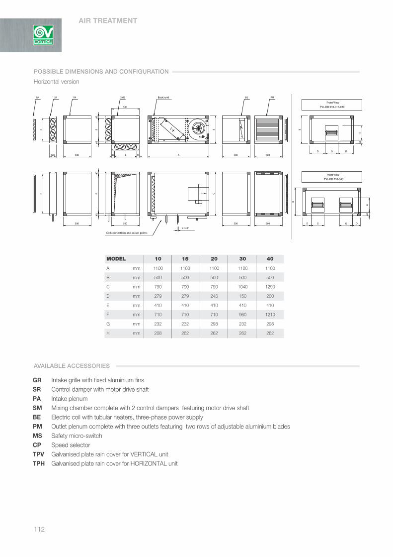
AIR TREATMENT
112
MODEL 10 15 20 30 40
A mm 1100 1100 1100 1100 1100
B mm 500 500 500 500 500
C mm 790 790 790 1040 1290
D mm 279 279 246 150 200
E mm 410 410 410 410 410
F mm 710 710 710 960 1210
G mm 232 232 298 232 298
H mm 208 262 262 262 262
Coil connections and drain
Access pointsBasic unit
GR SR
PM PM
Coil connections and access points
GR SR PA SM2 Basic unit
Top View
Top View
TVL-DD 030-040
TVL-DD 010-015-020
Front View
TVL-DD 030-040
TVL-DD 010-015-020
Front View
PM
ø 3/4"
120
E
A
95
B
F
C50
0
D
B
G
500
D G
B
G D
60H
D
60H
500
120
F
500
E
G
40
500
F40
E45 45 A
45E
45
500
500
C
500
D G
B
B B
D
G D
60H
D
60H
SM SM
500
120
E
120
500
BE BE
500
500
BE
500
500
GR Intake grille with fixed aluminium finsSR Control damper with motor drive shaftPA Intake plenum SM Mixing chamber complete with 2 control dampers featuring motor drive shaftBE Electric coil with tubular heaters, three-phase power supplyPM Outlet plenum complete with three outlets featuring two rows of adjustable aluminium bladesMS Safety micro-switchCP Speed selectorTPV Galvanised plate rain cover for VERTICAL unitTPH Galvanised plate rain cover for HORIZONTAL unit
POSSIBLE DIMENSIONS AND CONFIGURATION
Horizontal version
AVAILABLE ACCESSORIES
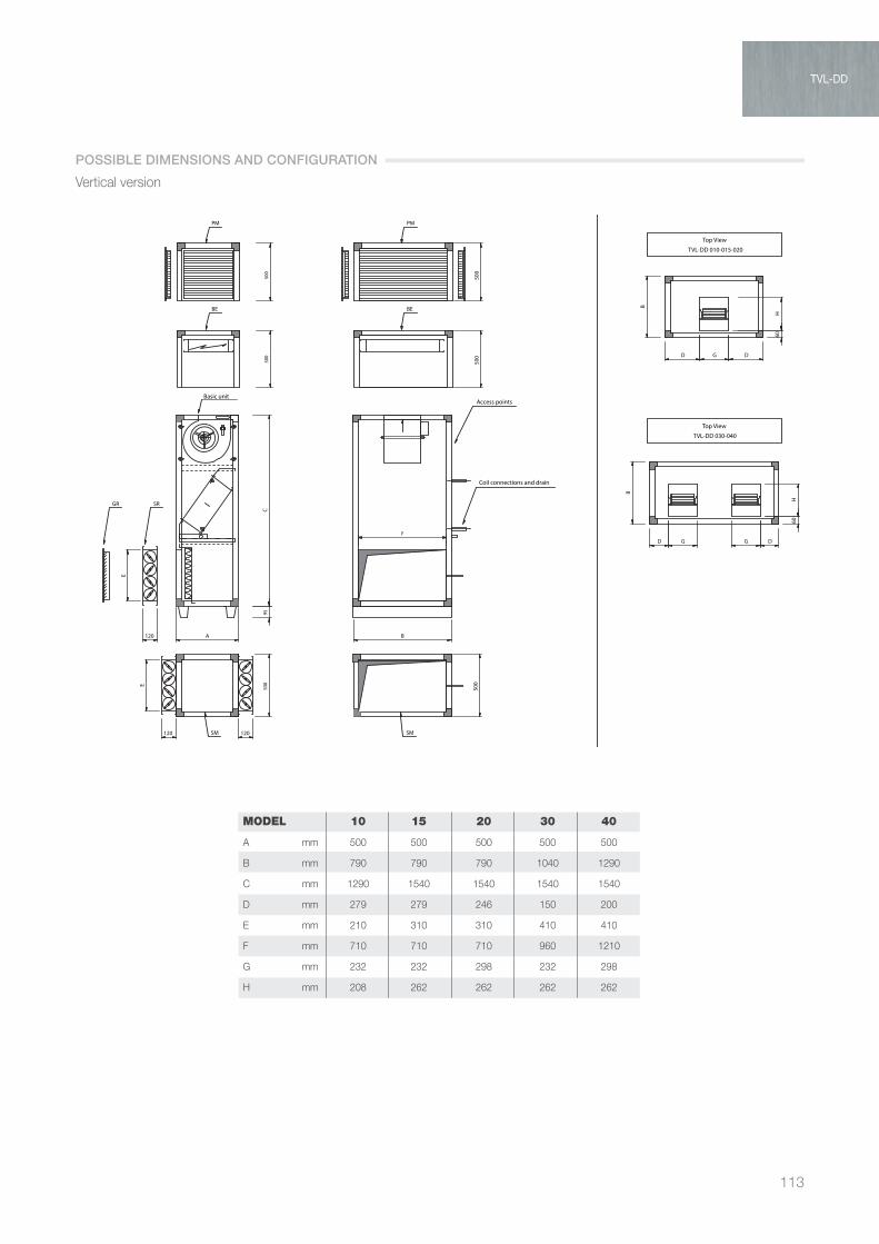
113
TVL-DD
MODEL 10 15 20 30 40
A mm 500 500 500 500 500
B mm 790 790 790 1040 1290
C mm 1290 1540 1540 1540 1540
D mm 279 279 246 150 200
E mm 210 310 310 410 410
F mm 710 710 710 960 1210
G mm 232 232 298 232 298
H mm 208 262 262 262 262
Coil connections and drain
Access pointsBasic unit
GR SR
PM PM
Coil connections and access points
GR SR PA SM2 Basic unit
Top View
Top View
TVL-DD 030-040
TVL-DD 010-015-020
Front View
TVL-DD 030-040
TVL-DD 010-015-020
Front View
PM
ø 3/4"
120
E
A
95
B
F
C50
0
D
B
G
500
D G
B
G D
60H
D
60H
500
120
F
500
E
G
40
500
F40
E45 45 A
45E
45
500
500
C
500
D G
B
B B
D
G D
60H
D
60H
SM SM
500
120
E
120
500
BE BE
500
500
BE
500
500
Vertical version
POSSIBLE DIMENSIONS AND CONFIGURATION
TVL-DD
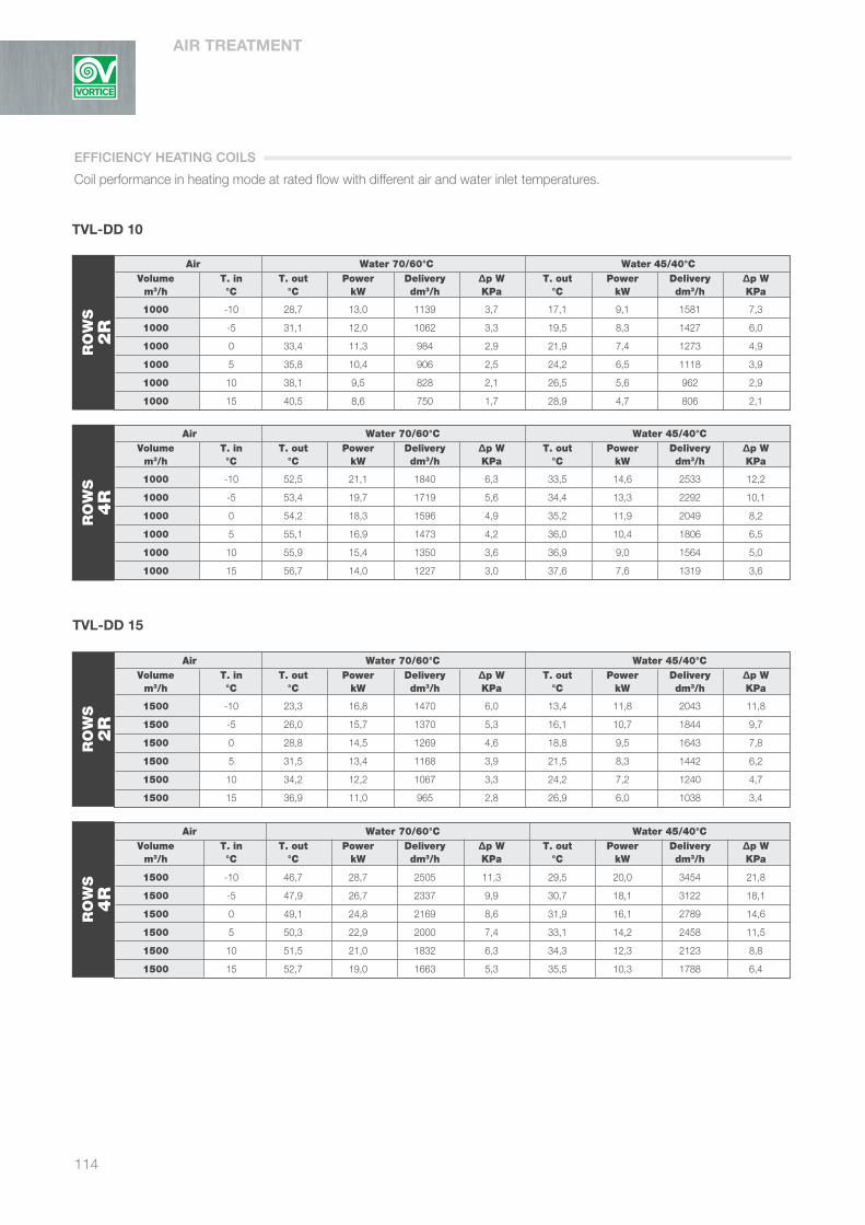
Air Water 70/60°C Water 45/40°C Volume T. in T. out Power Delivery ∆p W T. out Power Delivery ∆p W m3/h °C °C kW dm3/h KPa °C kW dm3/h KPa
1000 -10 28,7 13,0 1139 3,7 17,1 9,1 1581 7,3
1000 -5 31,1 12,0 1062 3,3 19,5 8,3 1427 6,0
1000 0 33,4 11,3 984 2,9 21,9 7,4 1273 4,9
1000 5 35,8 10,4 906 2,5 24,2 6,5 1118 3,9
1000 10 38,1 9,5 828 2,1 26,5 5,6 962 2,9
1000 15 40,5 8,6 750 1,7 28,9 4,7 806 2,1
Air Water 70/60°C Water 45/40°C Volume T. in T. out Power Delivery ∆p W T. out Power Delivery ∆p W m3/h °C °C kW dm3/h KPa °C kW dm3/h KPa
1000 -10 52,5 21,1 1840 6,3 33,5 14,6 2533 12,2
1000 -5 53,4 19,7 1719 5,6 34,4 13,3 2292 10,1
1000 0 54,2 18,3 1596 4,9 35,2 11,9 2049 8,2
1000 5 55,1 16,9 1473 4,2 36,0 10,4 1806 6,5
1000 10 55,9 15,4 1350 3,6 36,9 9,0 1564 5,0
1000 15 56,7 14,0 1227 3,0 37,6 7,6 1319 3,6
Air Water 70/60°C Water 45/40°C Volume T. in T. out Power Delivery ∆p W T. out Power Delivery ∆p W m3/h °C °C kW dm3/h KPa °C kW dm3/h KPa
1500 -10 23,3 16,8 1470 6,0 13,4 11,8 2043 11,8
1500 -5 26,0 15,7 1370 5,3 16,1 10,7 1844 9,7
1500 0 28,8 14,5 1269 4,6 18,8 9,5 1643 7,8
1500 5 31,5 13,4 1168 3,9 21,5 8,3 1442 6,2
1500 10 34,2 12,2 1067 3,3 24,2 7,2 1240 4,7
1500 15 36,9 11,0 965 2,8 26,9 6,0 1038 3,4
Air Water 70/60°C Water 45/40°C Volume T. in T. out Power Delivery ∆p W T. out Power Delivery ∆p W m3/h °C °C kW dm3/h KPa °C kW dm3/h KPa
1500 -10 46,7 28,7 2505 11,3 29,5 20,0 3454 21,8
1500 -5 47,9 26,7 2337 9,9 30,7 18,1 3122 18,1
1500 0 49,1 24,8 2169 8,6 31,9 16,1 2789 14,6
1500 5 50,3 22,9 2000 7,4 33,1 14,2 2458 11,5
1500 10 51,5 21,0 1832 6,3 34,3 12,3 2123 8,8
1500 15 52,7 19,0 1663 5,3 35,5 10,3 1788 6,4
EFFICIENCY HEATING COILS
114
TVL-DD 10
RO
WS
2R
RO
WS
4R
TVL-DD 15
RO
WS
2R
RO
WS
4R
Coil performance in heating mode at rated flow with different air and water inlet temperatures.
AIR TREATMENT

115
Air Water 70/60°C Water 45/40°C Volume T. in T. out Power Delivery ∆p W T. out Power Delivery ∆p W m3/h °C °C kW dm3/h KPa °C kW dm3/h KPa
2000 -10 19,6 19,9 1741 8,3 10,8 14,0 2423 16,2
2000 -5 22,6 18,6 1622 7,2 13,8 12,6 2185 13,4
2000 0 25,5 17,2 1503 6,3 16,7 11,3 1947 10,8
2000 5 28,5 15,8 1383 5,4 19,7 9,9 1708 8,4
2000 10 31,4 14,4 1262 4,5 22,6 8,5 1468 6,4
2000 15 34,4 13,1 1141 3,8 25,5 7,1 1228 4,6
Air Water 70/60°C Water 45/40°C Volume T. in T. out Power Delivery ∆p W T. out Power Delivery ∆p W m3/h °C °C kW dm3/h KPa °C kW dm3/h KPa
3000 -10 18,2 28,4 2487 6,7 9,8 20,0 3464 13,1
3000 -5 21,2 26,5 2316 5,9 12,9 18,1 3122 10,8
3000 0 24,3 24,5 2144 5,1 15,9 16,1 2780 8,7
3000 5 27,3 22,6 1971 4,3 18,9 14,1 2436 6,8
3000 10 30,4 20,6 1798 3,7 22,0 12,1 2091 5,2
3000 15 33,4 18,6 1624 3,0 25,0 10,1 1745 3,7
Air Water 70/60°C Water 45/40°C Volume T. in T. out Power Delivery ∆p W T. out Power Delivery ∆p W m3/h °C °C kW dm3/h KPa °C kW dm3/h KPa
4000 -10 39,0 65,9 5762 7,6 24,3 46,1 7978 14,9
4000 -5 40,6 61,4 5367 6,7 25,9 41,6 7196 12,3
4000 0 42,3 56,9 4973 5,8 27,5 37,1 6415 9,9
4000 5 43,9 52,4 4577 5,0 29,2 32,6 5632 7,8
4000 10 45,5 47,8 4181 4,2 30,8 28,0 4847 5,9
4000 15 47,1 43,3 3783 3,5 32,4 23,5 4060 4,2
TVL-DD
TVL-DD 20
RO
WS
2R
Air Water 70/60°C Water 45/40°C Volume T. in T. out Power Delivery ∆p W T. out Power Delivery ∆p W m3/h °C °C kW dm3/h KPa °C kW dm3/h KPa
2000 -10 42,2 35,2 3073 16,6 26,4 24,5 4243 32,1
2000 -5 43,7 32,8 2867 14,6 27,9 22,2 3835 26,6
2000 0 45,2 30,4 2660 12,7 29,4 19,7 3424 21,5
2000 5 46,7 28,1 2452 10,9 30,9 17,4 3014 16,9
2000 10 48,1 25,7 2244 9,2 32,4 15,1 2602 12,8
2000 15 49,6 23,3 2036 7,7 33,8 12,7 2190 9,3
RO
WS
4R
TVL-DD 30
RO
WS
2R
Air Water 70/60°C Water 45/40°C Volume T. in T. out Power Delivery ∆p W T. out Power Delivery ∆p W m3/h °C °C kW dm3/h KPa °C kW dm3/h KPa
3000 -10 40,7 51,2 4472 16,9 25,4 35,7 6179 32,7
3000 -5 42,3 47,7 4171 14,8 26,9 32,3 5582 27,1
3000 0 43,8 44,3 3868 12,9 28,5 28,8 4984 21,9
3000 5 45,4 40,8 3566 11,1 30,1 25,4 4387 17,3
3000 10 47 37,3 3264 9,4 31,7 21,9 3784 13,2
3000 15 48,5 33,9 2959 7,8 33,2 18,4 3183 9,6
RO
WS
4R
Air Water 70/60°C Water 45/40°C Volume T. in T. out Power Delivery ∆p W T. out Power Delivery ∆p W m3/h °C °C kW dm3/h KPa °C kW dm3/h KPa
4000 -10 17,9 37,6 3286 12,8 9,6 26,4 4571 25,2
4000 -5 21,0 35,0 3062 11,3 12,7 23,9 4124 20,8
4000 0 24,1 32,5 2838 9,8 15,8 21,3 3676 16,8
4000 5 27,2 29,9 2612 8,4 18,9 18,7 3227 13,2
4000 10 30,3 27,3 2385 7,1 21,9 16,1 2776 10,0
4000 15 33,3 24,7 2158 5,9 25,0 13,4 2323 7,2
TVL-DD 40
RO
WS
2R
RO
WS
4R
TVL-DD

Air Water 7/12°C Water 8/13°C
Volume T. in U.R. T. out Power S/T Delivery ∆p W T. out Power S/T Delivery ∆p W m3/h °C % °C kW dm3/h KPa °C kW dm3/h KPa
1000 35 60 17,5 13,8 0,4 2376 12,1 18,2 13,1 0,4 2259 11,0
1000 32 50 15,9 9,1 0,6 1559 5,6 16,6 8,4 0,6 1447 4,8
1000 28 50 14,7 6,2 0,7 1060 2,7 15,3 5,6 0,8 966 2,3
1000 26 50 14,1 5,0 0,8 850 1,8 14,7 4,5 0,8 771 1,5
Air Water 7/12°C Water 8/13°C
Volume T. in U.R. T. out Power S/T Delivery ∆p W T. out Power S/T Delivery ∆p W m3/h °C % °C kW dm3/h KPa °C kW dm3/h KPa
1000 35 60 14,9 16,3 0,4 2798 10,9 15,7 15,5 0,4 2670 10,0
1000 32 50 13,6 10,8 0,6 1861 5,2 14,5 10,1 0,6 1733 4,5
1000 28 50 12,7 7,58 0,7 1307 2,7 13,5 6,9 0,7 1190 2,3
1000 26 50 12,2 6,2 0,8 1066 1,9 13,0 5,6 0,8 962 1,5
Air Water 7/12°C Water 8/13°C
Volume T. in U.R. T. out Power S/T Delivery ∆p W T. out Power S/T Delivery ∆p W m3/h °C % °C kW dm3/h KPa °C kW dm3/h KPa
1500 35 60 17,5 13,8 0,4 2376 12,1 20,1 16,9 0,5 2901 17,4
1500 32 50 17,4 11,6 0,6 1995 8,8 18,2 10,5 0,7 1806 7,3
1500 28 50 15,9 7,9 0,8 1359 4,3 16,6 7,1 0,8 1220 3,5
1500 26 50 15,1 6,4 0,9 1101 2,9 15,7 5,8 0,9 997 2,4
Air Water 7/12°C Water 8/13°C
Volume T. in U.R. T. out Power S/T Delivery ∆p W T. out Power S/T Delivery ∆p W m3/h °C % °C kW dm3/h KPa °C kW dm3/h KPa
1500 35 60 16,9 21,6 0,4 3705 18,4 17,6 20,5 0,4 3523 16,6
1500 32 50 15,2 14,2 0,6 2438 8,5 15,9 13,3 0,6 2277 7,4
1500 28 50 13,9 9,9 0,7 1710 4,4 14,5 9,1 0,8 1569 3,8
1500 26 50 13,2 8,2 0,7 1408 3,1 13,8 7,5 0,8 1281 2,6
EFFICIENCY COOLING COILS
116
TVL-DD 10
RO
WS
4R
RO
WS
6R
TVL-DD 15
RO
WS
4R
RO
WS
6R
Coil performance in cooling mode at rated flow with different air and water inlet temperatures.
AIR TREATMENT
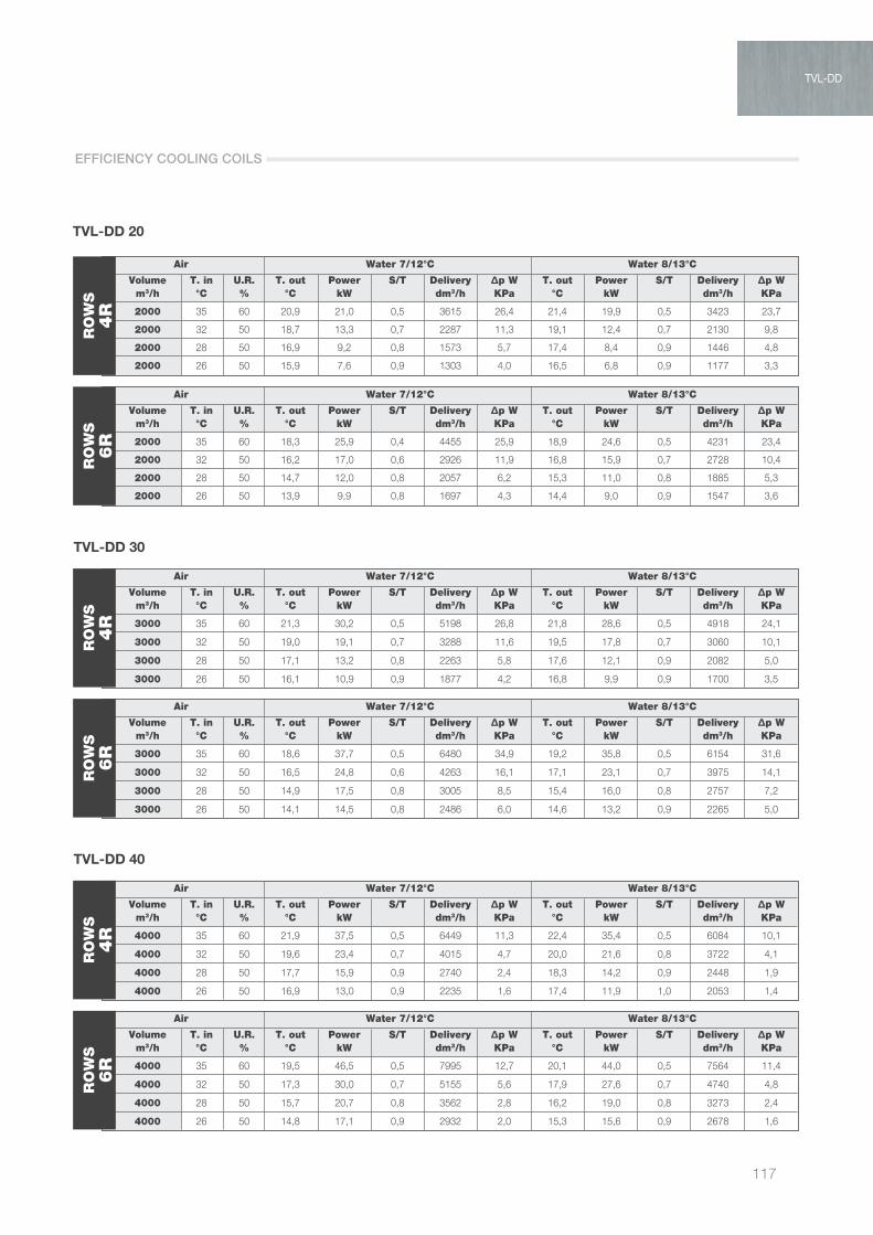
117
Air Water 7/12°C Water 8/13°C
Volume T. in U.R. T. out Power S/T Delivery ∆p W T. out Power S/T Delivery ∆p W m3/h °C % °C kW dm3/h KPa °C kW dm3/h KPa
2000 35 60 20,9 21,0 0,5 3615 26,4 21,4 19,9 0,5 3423 23,7
2000 32 50 18,7 13,3 0,7 2287 11,3 19,1 12,4 0,7 2130 9,8
2000 28 50 16,9 9,2 0,8 1573 5,7 17,4 8,4 0,9 1446 4,8
2000 26 50 15,9 7,6 0,9 1303 4,0 16,5 6,8 0,9 1177 3,3
Air Water 7/12°C Water 8/13°C
Volume T. in U.R. T. out Power S/T Delivery ∆p W T. out Power S/T Delivery ∆p W m3/h °C % °C kW dm3/h KPa °C kW dm3/h KPa
2000 35 60 18,3 25,9 0,4 4455 25,9 18,9 24,6 0,5 4231 23,4
2000 32 50 16,2 17,0 0,6 2926 11,9 16,8 15,9 0,7 2728 10,4
2000 28 50 14,7 12,0 0,8 2057 6,2 15,3 11,0 0,8 1885 5,3
2000 26 50 13,9 9,9 0,8 1697 4,3 14,4 9,0 0,9 1547 3,6
Air Water 7/12°C Water 8/13°C
Volume T. in U.R. T. out Power S/T Delivery ∆p W T. out Power S/T Delivery ∆p W m3/h °C % °C kW dm3/h KPa °C kW dm3/h KPa
3000 35 60 21,3 30,2 0,5 5198 26,8 21,8 28,6 0,5 4918 24,1
3000 32 50 19,0 19,1 0,7 3288 11,6 19,5 17,8 0,7 3060 10,1
3000 28 50 17,1 13,2 0,8 2263 5,8 17,6 12,1 0,9 2082 5,0
3000 26 50 16,1 10,9 0,9 1877 4,2 16,8 9,9 0,9 1700 3,5
Air Water 7/12°C Water 8/13°C
Volume T. in U.R. T. out Power S/T Delivery ∆p W T. out Power S/T Delivery ∆p W m3/h °C % °C kW dm3/h KPa °C kW dm3/h KPa
3000 35 60 18,6 37,7 0,5 6480 34,9 19,2 35,8 0,5 6154 31,6
3000 32 50 16,5 24,8 0,6 4263 16,1 17,1 23,1 0,7 3975 14,1
3000 28 50 14,9 17,5 0,8 3005 8,5 15,4 16,0 0,8 2757 7,2
3000 26 50 14,1 14,5 0,8 2486 6,0 14,6 13,2 0,9 2265 5,0
Air Water 7/12°C Water 8/13°C
Volume T. in U.R. T. out Power S/T Delivery ∆p W T. out Power S/T Delivery ∆p W m3/h °C % °C kW dm3/h KPa °C kW dm3/h KPa
4000 35 60 21,9 37,5 0,5 6449 11,3 22,4 35,4 0,5 6084 10,1
4000 32 50 19,6 23,4 0,7 4015 4,7 20,0 21,6 0,8 3722 4,1
4000 28 50 17,7 15,9 0,9 2740 2,4 18,3 14,2 0,9 2448 1,9
4000 26 50 16,9 13,0 0,9 2235 1,6 17,4 11,9 1,0 2053 1,4
Air Water 7/12°C Water 8/13°C
Volume T. in U.R. T. out Power S/T Delivery ∆p W T. out Power S/T Delivery ∆p W m3/h °C % °C kW dm3/h KPa °C kW dm3/h KPa
4000 35 60 19,5 46,5 0,5 7995 12,7 20,1 44,0 0,5 7564 11,4
4000 32 50 17,3 30,0 0,7 5155 5,6 17,9 27,6 0,7 4740 4,8
4000 28 50 15,7 20,7 0,8 3562 2,8 16,2 19,0 0,8 3273 2,4
4000 26 50 14,8 17,1 0,9 2932 2,0 15,3 15,6 0,9 2678 1,6
TVL-DD 20
RO
WS
4R
RO
WS
6R
TVL-DD 30
RO
WS
4R
RO
WS
6R
TVL-DD 40
RO
WS
4R
RO
WS
6R
EFFICIENCY COOLING COILS
TVL-DD

AIR TREATMENT
118
TVL-DD 10
Model Outlet fan (BAC 2R) Outlet fan (BAC 4R) Outlet fan (BAF 4R) Outlet fan (BAF 6R)
Flow-rate Air vel. Available static pressure (Pa) Available static pressure (Pa) Available static pressure (Pa) Available static pressure (Pa) m3/h m/s Vel. 1° Vel. 2° Vel. 3° Vel. 1° Vel. 2° Vel. 3° Vel. 1° Vel. 2° Vel. 3° Vel. 1° Vel. 2° Vel. 3°
500 0,57 230 212 183 228 210 181 223 205 176 218 200 171
600 0,68 224 201 161 221 198 158 215 192 152 208 185 145
700 0,80 215 180 135 211 176 131 203 168 123 195 160 115
800 0,91 209 169 104 204 164 99 195 155 90 184 144 79
900 1,03 201 153 - 195 147 - 184 136 - 171 123 -
1000 1,14 196 119 - 189 112 - 176 99 - 161 84 -
1100 1,25 189 - - 181 - - 165 - - 148 - -
1200 1,37 180 - - 170 - - 153 - - 133 - -
1300 1,48 154 - - 143 - - 123 - - 101 - -
Model Outlet fan (BAC 2R) Outlet fan (BAC 4R) Outlet fan (BAF 4R) Outlet fan (BAF 6R)
Flow-rate Air vel. Available static pressure (Pa) Available static pressure (Pa) Available static pressure (Pa) Available static pressure (Pa) m3/h m/s Vel. 1° Vel. 2° Vel. 3° Vel. 1° Vel. 2° Vel. 3° Vel. 1° Vel. 2° Vel. 3° Vel. 1° Vel. 2° Vel. 3°
900 1,03 318 308 223 312 302 217 301 291 206 288 278 193
1050 1,20 312 290 182 304 282 174 289 267 159 274 252 144
1200 1,37 322 270 - 312 260 - 295 243 - 275 223 -
1350 1,54 318 246 - 306 234 - 286 214 - 268 196 -
1500 1,71 304 - - 290 205 - 266 181 - 245 160 -
1650 1,88 289 - - 273 - - 245 - - 221 - -
1800 2,05 262 - - 243 - - 212 - - 184 - -
1950 2,22 220 - - 199 - - 163 - - 132 - -
TVL-DD 15
Model Outlet fan (BAC 2R) Outlet fan (BAC 4R) Outlet fan (BAF 4R) Outlet fan (BAF 6R)
Flow-rate Air vel. Available static pressure (Pa) Available static pressure (Pa) Available static pressure (Pa) Available static pressure (Pa) m3/h m/s Vel. 1° Vel. 2° Vel. 3° Vel. 1° Vel. 2° Vel. 3° Vel. 1° Vel. 2° Vel. 3° Vel. 1° Vel. 2° Vel. 3°
1000 1,14 327 277 137 320 270 130 307 257 117 292 242 102
1200 1,37 290 235 - 280 225 - 263 208 - 243 188 -
1400 1,60 267 202 - 255 190 - 233 168 - 214 149 -
1600 1,82 260 195 - 244 179 - 218 153 - 195 130 -
1800 2,05 262 - - 243 118 - 212 87 - 184 59 -
2000 2,28 257 - - 235 - - 208 - - 166 - -
2200 2,51 211 - - 186 - - 154 - - 105 - -
TVL-DD 20
FAN PERFORMANCE
Residual pressure available at the fans at different speeds and with different coils.

119
TVL-DD 30
Model Outlet fan (BAC 2R) Outlet fan (BAC 4R) Outlet fan (BAF 4R) Outlet fan (BAF 6R)
Flow-rate Air vel. Available static pressure (Pa) Available static pressure (Pa) Available static pressure (Pa) Available static pressure (Pa) m3/h m/s Vel. 1° Vel. 2° Vel. 3° Vel. 1° Vel. 2° Vel. 3° Vel. 1° Vel. 2° Vel. 3° Vel. 1° Vel. 2° Vel. 3°
1000 0,84 345 325 290 340 320 285 332 312 277 323 303 268
1500 1,26 308 301 223 299 292 214 284 277 199 267 260 182
2000 1,67 292 272 177 278 258 163 255 235 140 234 214 119
2500 2,09 296 238 - 277 219 - 245 187 - 216 158 -
3000 2,51 266 181 - 241 156 - 209 124 - 160 75 -
3250 2,72 243 - - 214 84 - 178 48 - 124 - -
3500 2,93 216 - - 183 - - 143 - - 81 - -
Model Outlet fan (BAC 2R) Outlet fan (BAC 4R) Outlet fan (BAF 4R) Outlet fan (BAF 6R)
Flow-rate Air vel. Available static pressure (Pa) Available static pressure (Pa) Available static pressure (Pa) Available static pressure (Pa) m3/h m/s Vel. 1° Vel. 2° Vel. 3° Vel. 1° Vel. 2° Vel. 3° Vel. 1° Vel. 2° Vel. 3° Vel. 1° Vel. 2° Vel. 3°
1500 0,99 354 314 239 348 308 233 337 297 222 325 285 210
2000 1,32 315 265 125 306 256 116 290 240 100 275 225 85
2500 1,65 277 217 - 263 203 - 241 181 - 221 161 -
3000 1,98 250 185 - 232 167 - 210 145 - 176 111 -
3500 2,31 248 158 - 226 136 - 198 108 - 155 65 -
4000 2,65 234 - - 207 - - 172 - - 120 - -
4500 2,98 169 - - 136 - - 95 - - 32 - -
TVL-DD 40
MODEL CONFIGURATION EXCHANGER ACCESSORIES
TVL 10 DD H 4 COILS MS, CP...
FAN PERFORMANCE
SAMPLE ORDER
TVL-DD

AIR TREATMENT
120
TLV 10 + 2-row coil
TVL 10 + Batteria 2 Ranghi
0
50
100
150
200
250
Le curve tengono conto delle perdite di caricodovute alla batteria ed ai filtri
TVL 10 + Batteria 4 Ranghi
59.3 dB(A)
55.6 dB(A)
54.5 dB(A)
54 dB(A)
50.9 dB(A)
51.2 dB(A)
51.5 dB(A)
TVL 10 + Batteria 6 Ranghi
59.6 dB(A)
59.3 dB(A)
54 dB(A)
50.9 dB(A)
51.2 dB(A)
51.5 dB(A)
59.6 dB(A)
59.3 dB(A)
55.6 dB(A)50.9 dB(A)
51.2 dB(A)
51.5 dB(A)
56.4 dB(A)
57.2 dB(A)
TVL 15 + Batteria 2 ranghi
50
100
150
200
250
300
350
360
TVL 15 + Batteria 4 ranghi TVL 15 + Batteria 6 ranghi
TVL 20 + Batteria 2 ranghi TVL 20 + Batteria 4 ranghi TVL 20 + Batteria 6 ranghi
TVL 30 DD +2R TVL 30 DD +4R TVL 30 DD +6R
TVL 40DD+2R TVL 40DD+4R TVL 40DD+6R
62 dB(A)
62 dB(A)
64 dB(A)
60 dB(A)
54 dB(A)
55 dB(A)
62 dB(A)
62 dB(A)
64 dB(A)
59 dB(A)
60 dB(A)
55 dB(A)
54 dB(A)
62 dB(A)
64 dB(A)
62.2 dB(A)
59.2 dB(A)
60 dB(A)
54 dB(A)
64.5 dB(A)
65.5 dB(A)
65.5 dB(A)
61.2 dB(A)
60 dB(A) 65.5 dB(A)
64.5 dB(A)
65.5 dB(A)
61.2 dB(A)
60 dB(A)
65.5 dB(A)
64.5 dB(A)
65.5 dB(A)
60 dB(A)
61.2 dB(A)
62 dB(A)
60 dB(A)
55 dB(A)
62 dB(A)
62 dB(A)
60 dB(A)
60 dB(A)
55 dB(A)
62 dB(A)
62 dB(A)60 dB(A)
55 dB(A)
0 400 600 800 1000 1200 14000
50
100
150
200
250
0 400 600 800 1000 1200 14000
50
100
150
200
250
0 400 600 800 1000 1200 1400
0 400 800 1200 1600 2000 2400 0 400 800 1200 1600 2000 240050
100
150
200
250
300
350
360
50
100
150
200
250
300
350
360
0 400 800 1200 1600 2000 2400
62 dB(A)
50
100
150
200
250
300
350
360
0 400 800 1200 1600 2000 240050
100
150
200
250
300
350
360
0 400 800 1200 1600 2000 240050
100
150
200
250
300
350
360
0 400 800 1200 1600 2000 2400
600
500
400
300
200
100
00 500 1000 1500 2000 2500 3000 3500
60 dB(A)
62 dB(A)
600
500
400
300
200
100
00 500 1000 1500 2000 2500 3000 3500
600
500
400
300
200
100
00 500 1000 1500 2000 2500 3000 3500
400
350
300
250
200
150
100
50
00 1000 2000 3000 4000 5000
400
350
300
250
200
150
100
50
00 1000 2000 3000 4000 5000
400
350
300
250
200
150
100
50
00 1000 2000 3000 4000 5000
Air flow (m3/h) Air flow (m3/h) Air flow (m3/h)
Air flow (m3/h) Air flow (m3/h)Air flow (m3/h)
Air flow (m3/h) Air flow (m3/h) Air flow (m3/h)
Air flow (m3/h) Air flow (m3/h) Air flow (m3/h)
Air flow (m3/h) Air flow (m3/h)Air flow (m3/h)
Stat
ic p
ress
ure
(Pa)
Stat
ic p
ress
ure
(Pa)
Stat
ic p
ress
ure
(Pa)
Stat
ic p
ress
ure
(Pa)
Stat
ic p
ress
ure
(Pa)
Stat
ic p
ress
ure
(Pa)
Stat
ic p
ress
ure
(Pa)
Stat
ic p
ress
ure
(Pa)
Stat
ic p
ress
ure
(Pa)
Stat
ic p
ress
ure
(Pa)
Stat
ic p
ress
ure
(Pa)
Stat
ic p
ress
ure
(Pa)
Stat
ic p
ress
ure
(Pa)
Stat
ic p
ress
ure
(Pa)
Stat
ic p
ress
ure
(Pa)
53 dB(A)
61 dB(A)
64 dB(A)
65 dB(A)
53 dB(A)
61 dB(A)
64 dB(A)
65 dB(A)
53 dB(A)
61 dB(A)65 dB(A)
64 dB(A)
54.6 dB(A)
54.6 dB(A)
54.6 dB(A)
59.6 dB(A)
55.6 dB(A)
54.5 dB(A)
TLV 10 + 4-row coil
The curves take into consideration pressure drop due to the coil and the filters
CHARACTERISTIC CURVES

121
TLV 10 + 6-row coilTVL 10 + Batteria 2 Ranghi
0
50
100
150
200
250
Le curve tengono conto delle perdite di caricodovute alla batteria ed ai filtri
TVL 10 + Batteria 4 Ranghi
59.3 dB(A)
55.6 dB(A)
54.5 dB(A)
54 dB(A)
50.9 dB(A)
51.2 dB(A)
51.5 dB(A)
TVL 10 + Batteria 6 Ranghi
59.6 dB(A)
59.3 dB(A)
54 dB(A)
50.9 dB(A)
51.2 dB(A)
51.5 dB(A)
59.6 dB(A)
59.3 dB(A)
55.6 dB(A)50.9 dB(A)
51.2 dB(A)
51.5 dB(A)
56.4 dB(A)
57.2 dB(A)
TVL 15 + Batteria 2 ranghi
50
100
150
200
250
300
350
360
TVL 15 + Batteria 4 ranghi TVL 15 + Batteria 6 ranghi
TVL 20 + Batteria 2 ranghi TVL 20 + Batteria 4 ranghi TVL 20 + Batteria 6 ranghi
TVL 30 DD +2R TVL 30 DD +4R TVL 30 DD +6R
TVL 40DD+2R TVL 40DD+4R TVL 40DD+6R
62 dB(A)
62 dB(A)
64 dB(A)
60 dB(A)
54 dB(A)
55 dB(A)
62 dB(A)
62 dB(A)
64 dB(A)
59 dB(A)
60 dB(A)
55 dB(A)
54 dB(A)
62 dB(A)
64 dB(A)
62.2 dB(A)
59.2 dB(A)
60 dB(A)
54 dB(A)
64.5 dB(A)
65.5 dB(A)
65.5 dB(A)
61.2 dB(A)
60 dB(A) 65.5 dB(A)
64.5 dB(A)
65.5 dB(A)
61.2 dB(A)
60 dB(A)
65.5 dB(A)
64.5 dB(A)
65.5 dB(A)
60 dB(A)
61.2 dB(A)
62 dB(A)
60 dB(A)
55 dB(A)
62 dB(A)
62 dB(A)
60 dB(A)
60 dB(A)
55 dB(A)
62 dB(A)
62 dB(A)60 dB(A)
55 dB(A)
0 400 600 800 1000 1200 14000
50
100
150
200
250
0 400 600 800 1000 1200 14000
50
100
150
200
250
0 400 600 800 1000 1200 1400
0 400 800 1200 1600 2000 2400 0 400 800 1200 1600 2000 240050
100
150
200
250
300
350
360
50
100
150
200
250
300
350
360
0 400 800 1200 1600 2000 2400
62 dB(A)
50
100
150
200
250
300
350
360
0 400 800 1200 1600 2000 240050
100
150
200
250
300
350
360
0 400 800 1200 1600 2000 240050
100
150
200
250
300
350
360
0 400 800 1200 1600 2000 2400
600
500
400
300
200
100
00 500 1000 1500 2000 2500 3000 3500
60 dB(A)
62 dB(A)
600
500
400
300
200
100
00 500 1000 1500 2000 2500 3000 3500
600
500
400
300
200
100
00 500 1000 1500 2000 2500 3000 3500
400
350
300
250
200
150
100
50
00 1000 2000 3000 4000 5000
400
350
300
250
200
150
100
50
00 1000 2000 3000 4000 5000
400
350
300
250
200
150
100
50
00 1000 2000 3000 4000 5000
Air flow (m3/h) Air flow (m3/h) Air flow (m3/h)
Air flow (m3/h) Air flow (m3/h)Air flow (m3/h)
Air flow (m3/h) Air flow (m3/h) Air flow (m3/h)
Air flow (m3/h) Air flow (m3/h) Air flow (m3/h)
Air flow (m3/h) Air flow (m3/h)Air flow (m3/h)
Stat
ic p
ress
ure
(Pa)
Stat
ic p
ress
ure
(Pa)
Stat
ic p
ress
ure
(Pa)
Stat
ic p
ress
ure
(Pa)
Stat
ic p
ress
ure
(Pa)
Stat
ic p
ress
ure
(Pa)
Stat
ic p
ress
ure
(Pa)
Stat
ic p
ress
ure
(Pa)
Stat
ic p
ress
ure
(Pa)
Stat
ic p
ress
ure
(Pa)
Stat
ic p
ress
ure
(Pa)
Stat
ic p
ress
ure
(Pa)
Stat
ic p
ress
ure
(Pa)
Stat
ic p
ress
ure
(Pa)
Stat
ic p
ress
ure
(Pa)
53 dB(A)
61 dB(A)
64 dB(A)
65 dB(A)
53 dB(A)
61 dB(A)
64 dB(A)
65 dB(A)
53 dB(A)
61 dB(A)65 dB(A)
64 dB(A)
54.6 dB(A)
54.6 dB(A)
54.6 dB(A)
59.6 dB(A)
55.6 dB(A)
54.5 dB(A)
TLV 15 + 2-row coil
TVL 10 + Batteria 2 Ranghi
0
50
100
150
200
250
Le curve tengono conto delle perdite di caricodovute alla batteria ed ai filtri
TVL 10 + Batteria 4 Ranghi
59.3 dB(A)
55.6 dB(A)
54.5 dB(A)
54 dB(A)
50.9 dB(A)
51.2 dB(A)
51.5 dB(A)
TVL 10 + Batteria 6 Ranghi
59.6 dB(A)
59.3 dB(A)
54 dB(A)
50.9 dB(A)
51.2 dB(A)
51.5 dB(A)
59.6 dB(A)
59.3 dB(A)
55.6 dB(A)50.9 dB(A)
51.2 dB(A)
51.5 dB(A)
56.4 dB(A)
57.2 dB(A)
TVL 15 + Batteria 2 ranghi
50
100
150
200
250
300
350
360
TVL 15 + Batteria 4 ranghi TVL 15 + Batteria 6 ranghi
TVL 20 + Batteria 2 ranghi TVL 20 + Batteria 4 ranghi TVL 20 + Batteria 6 ranghi
TVL 30 DD +2R TVL 30 DD +4R TVL 30 DD +6R
TVL 40DD+2R TVL 40DD+4R TVL 40DD+6R
62 dB(A)
62 dB(A)
64 dB(A)
60 dB(A)
54 dB(A)
55 dB(A)
62 dB(A)
62 dB(A)
64 dB(A)
59 dB(A)
60 dB(A)
55 dB(A)
54 dB(A)
62 dB(A)
64 dB(A)
62.2 dB(A)
59.2 dB(A)
60 dB(A)
54 dB(A)
64.5 dB(A)
65.5 dB(A)
65.5 dB(A)
61.2 dB(A)
60 dB(A) 65.5 dB(A)
64.5 dB(A)
65.5 dB(A)
61.2 dB(A)
60 dB(A)
65.5 dB(A)
64.5 dB(A)
65.5 dB(A)
60 dB(A)
61.2 dB(A)
62 dB(A)
60 dB(A)
55 dB(A)
62 dB(A)
62 dB(A)
60 dB(A)
60 dB(A)
55 dB(A)
62 dB(A)
62 dB(A)60 dB(A)
55 dB(A)
0 400 600 800 1000 1200 14000
50
100
150
200
250
0 400 600 800 1000 1200 14000
50
100
150
200
250
0 400 600 800 1000 1200 1400
0 400 800 1200 1600 2000 2400 0 400 800 1200 1600 2000 240050
100
150
200
250
300
350
360
50
100
150
200
250
300
350
360
0 400 800 1200 1600 2000 2400
62 dB(A)
50
100
150
200
250
300
350
360
0 400 800 1200 1600 2000 240050
100
150
200
250
300
350
360
0 400 800 1200 1600 2000 240050
100
150
200
250
300
350
360
0 400 800 1200 1600 2000 2400
600
500
400
300
200
100
00 500 1000 1500 2000 2500 3000 3500
60 dB(A)
62 dB(A)
600
500
400
300
200
100
00 500 1000 1500 2000 2500 3000 3500
600
500
400
300
200
100
00 500 1000 1500 2000 2500 3000 3500
400
350
300
250
200
150
100
50
00 1000 2000 3000 4000 5000
400
350
300
250
200
150
100
50
00 1000 2000 3000 4000 5000
400
350
300
250
200
150
100
50
00 1000 2000 3000 4000 5000
Air flow (m3/h) Air flow (m3/h) Air flow (m3/h)
Air flow (m3/h) Air flow (m3/h)Air flow (m3/h)
Air flow (m3/h) Air flow (m3/h) Air flow (m3/h)
Air flow (m3/h) Air flow (m3/h) Air flow (m3/h)
Air flow (m3/h) Air flow (m3/h)Air flow (m3/h)
Stat
ic p
ress
ure
(Pa)
Stat
ic p
ress
ure
(Pa)
Stat
ic p
ress
ure
(Pa)
Stat
ic p
ress
ure
(Pa)
Stat
ic p
ress
ure
(Pa)
Stat
ic p
ress
ure
(Pa)
Stat
ic p
ress
ure
(Pa)
Stat
ic p
ress
ure
(Pa)
Stat
ic p
ress
ure
(Pa)
Stat
ic p
ress
ure
(Pa)
Stat
ic p
ress
ure
(Pa)
Stat
ic p
ress
ure
(Pa)
Stat
ic p
ress
ure
(Pa)
Stat
ic p
ress
ure
(Pa)
Stat
ic p
ress
ure
(Pa)
53 dB(A)
61 dB(A)
64 dB(A)
65 dB(A)
53 dB(A)
61 dB(A)
64 dB(A)
65 dB(A)
53 dB(A)
61 dB(A)65 dB(A)
64 dB(A)
54.6 dB(A)
54.6 dB(A)
54.6 dB(A)
59.6 dB(A)
55.6 dB(A)
54.5 dB(A)
The curves take into consideration pressure drop due to the coil and the filters
TVL-DD
CHARACTERISTIC CURVES
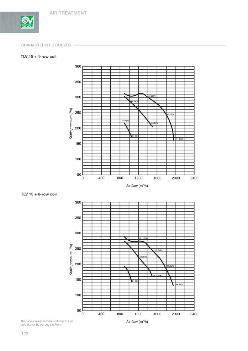
AIR TREATMENT
122
TLV 15 + 4-row coil
TVL 10 + Batteria 2 Ranghi
0
50
100
150
200
250
Le curve tengono conto delle perdite di caricodovute alla batteria ed ai filtri
TVL 10 + Batteria 4 Ranghi
59.3 dB(A)
55.6 dB(A)
54.5 dB(A)
54 dB(A)
50.9 dB(A)
51.2 dB(A)
51.5 dB(A)
TVL 10 + Batteria 6 Ranghi
59.6 dB(A)
59.3 dB(A)
54 dB(A)
50.9 dB(A)
51.2 dB(A)
51.5 dB(A)
59.6 dB(A)
59.3 dB(A)
55.6 dB(A)50.9 dB(A)
51.2 dB(A)
51.5 dB(A)
56.4 dB(A)
57.2 dB(A)
TVL 15 + Batteria 2 ranghi
50
100
150
200
250
300
350
360
TVL 15 + Batteria 4 ranghi TVL 15 + Batteria 6 ranghi
TVL 20 + Batteria 2 ranghi TVL 20 + Batteria 4 ranghi TVL 20 + Batteria 6 ranghi
TVL 30 DD +2R TVL 30 DD +4R TVL 30 DD +6R
TVL 40DD+2R TVL 40DD+4R TVL 40DD+6R
62 dB(A)
62 dB(A)
64 dB(A)
60 dB(A)
54 dB(A)
55 dB(A)
62 dB(A)
62 dB(A)
64 dB(A)
59 dB(A)
60 dB(A)
55 dB(A)
54 dB(A)
62 dB(A)
64 dB(A)
62.2 dB(A)
59.2 dB(A)
60 dB(A)
54 dB(A)
64.5 dB(A)
65.5 dB(A)
65.5 dB(A)
61.2 dB(A)
60 dB(A) 65.5 dB(A)
64.5 dB(A)
65.5 dB(A)
61.2 dB(A)
60 dB(A)
65.5 dB(A)
64.5 dB(A)
65.5 dB(A)
60 dB(A)
61.2 dB(A)
62 dB(A)
60 dB(A)
55 dB(A)
62 dB(A)
62 dB(A)
60 dB(A)
60 dB(A)
55 dB(A)
62 dB(A)
62 dB(A)60 dB(A)
55 dB(A)
0 400 600 800 1000 1200 14000
50
100
150
200
250
0 400 600 800 1000 1200 14000
50
100
150
200
250
0 400 600 800 1000 1200 1400
0 400 800 1200 1600 2000 2400 0 400 800 1200 1600 2000 240050
100
150
200
250
300
350
360
50
100
150
200
250
300
350
360
0 400 800 1200 1600 2000 2400
62 dB(A)
50
100
150
200
250
300
350
360
0 400 800 1200 1600 2000 240050
100
150
200
250
300
350
360
0 400 800 1200 1600 2000 240050
100
150
200
250
300
350
360
0 400 800 1200 1600 2000 2400
600
500
400
300
200
100
00 500 1000 1500 2000 2500 3000 3500
60 dB(A)
62 dB(A)
600
500
400
300
200
100
00 500 1000 1500 2000 2500 3000 3500
600
500
400
300
200
100
00 500 1000 1500 2000 2500 3000 3500
400
350
300
250
200
150
100
50
00 1000 2000 3000 4000 5000
400
350
300
250
200
150
100
50
00 1000 2000 3000 4000 5000
400
350
300
250
200
150
100
50
00 1000 2000 3000 4000 5000
Air flow (m3/h) Air flow (m3/h) Air flow (m3/h)
Air flow (m3/h) Air flow (m3/h)Air flow (m3/h)
Air flow (m3/h) Air flow (m3/h) Air flow (m3/h)
Air flow (m3/h) Air flow (m3/h) Air flow (m3/h)
Air flow (m3/h) Air flow (m3/h)Air flow (m3/h)
Stat
ic p
ress
ure
(Pa)
Stat
ic p
ress
ure
(Pa)
Stat
ic p
ress
ure
(Pa)
Stat
ic p
ress
ure
(Pa)
Stat
ic p
ress
ure
(Pa)
Stat
ic p
ress
ure
(Pa)
Stat
ic p
ress
ure
(Pa)
Stat
ic p
ress
ure
(Pa)
Stat
ic p
ress
ure
(Pa)
Stat
ic p
ress
ure
(Pa)
Stat
ic p
ress
ure
(Pa)
Stat
ic p
ress
ure
(Pa)
Stat
ic p
ress
ure
(Pa)
Stat
ic p
ress
ure
(Pa)
Stat
ic p
ress
ure
(Pa)
53 dB(A)
61 dB(A)
64 dB(A)
65 dB(A)
53 dB(A)
61 dB(A)
64 dB(A)
65 dB(A)
53 dB(A)
61 dB(A)65 dB(A)
64 dB(A)
54.6 dB(A)
54.6 dB(A)
54.6 dB(A)
59.6 dB(A)
55.6 dB(A)
54.5 dB(A)
TLV 15 + 6-row coil
The curves take into consideration pressure drop due to the coil and the filters
CHARACTERISTIC CURVES
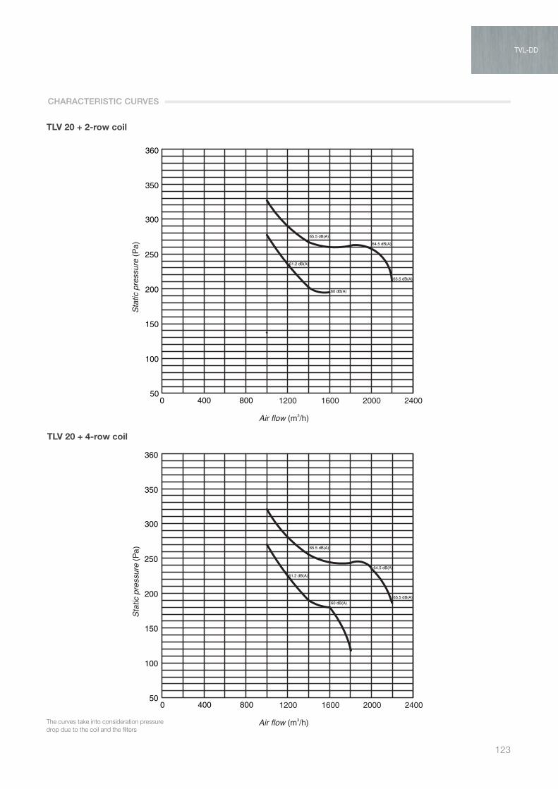
123
TLV 20 + 2-row coil
TVL 10 + Batteria 2 Ranghi
0
50
100
150
200
250
Le curve tengono conto delle perdite di caricodovute alla batteria ed ai filtri
TVL 10 + Batteria 4 Ranghi
59.3 dB(A)
55.6 dB(A)
54.5 dB(A)
54 dB(A)
50.9 dB(A)
51.2 dB(A)
51.5 dB(A)
TVL 10 + Batteria 6 Ranghi
59.6 dB(A)
59.3 dB(A)
54 dB(A)
50.9 dB(A)
51.2 dB(A)
51.5 dB(A)
59.6 dB(A)
59.3 dB(A)
55.6 dB(A)50.9 dB(A)
51.2 dB(A)
51.5 dB(A)
56.4 dB(A)
57.2 dB(A)
TVL 15 + Batteria 2 ranghi
50
100
150
200
250
300
350
360
TVL 15 + Batteria 4 ranghi TVL 15 + Batteria 6 ranghi
TVL 20 + Batteria 2 ranghi TVL 20 + Batteria 4 ranghi TVL 20 + Batteria 6 ranghi
TVL 30 DD +2R TVL 30 DD +4R TVL 30 DD +6R
TVL 40DD+2R TVL 40DD+4R TVL 40DD+6R
62 dB(A)
62 dB(A)
64 dB(A)
60 dB(A)
54 dB(A)
55 dB(A)
62 dB(A)
62 dB(A)
64 dB(A)
59 dB(A)
60 dB(A)
55 dB(A)
54 dB(A)
62 dB(A)
64 dB(A)
62.2 dB(A)
59.2 dB(A)
60 dB(A)
54 dB(A)
64.5 dB(A)
65.5 dB(A)
65.5 dB(A)
61.2 dB(A)
60 dB(A) 65.5 dB(A)
64.5 dB(A)
65.5 dB(A)
61.2 dB(A)
60 dB(A)
65.5 dB(A)
64.5 dB(A)
65.5 dB(A)
60 dB(A)
61.2 dB(A)
62 dB(A)
60 dB(A)
55 dB(A)
62 dB(A)
62 dB(A)
60 dB(A)
60 dB(A)
55 dB(A)
62 dB(A)
62 dB(A)60 dB(A)
55 dB(A)
0 400 600 800 1000 1200 14000
50
100
150
200
250
0 400 600 800 1000 1200 14000
50
100
150
200
250
0 400 600 800 1000 1200 1400
0 400 800 1200 1600 2000 2400 0 400 800 1200 1600 2000 240050
100
150
200
250
300
350
360
50
100
150
200
250
300
350
360
0 400 800 1200 1600 2000 2400
62 dB(A)
50
100
150
200
250
300
350
360
0 400 800 1200 1600 2000 240050
100
150
200
250
300
350
360
0 400 800 1200 1600 2000 240050
100
150
200
250
300
350
360
0 400 800 1200 1600 2000 2400
600
500
400
300
200
100
00 500 1000 1500 2000 2500 3000 3500
60 dB(A)
62 dB(A)
600
500
400
300
200
100
00 500 1000 1500 2000 2500 3000 3500
600
500
400
300
200
100
00 500 1000 1500 2000 2500 3000 3500
400
350
300
250
200
150
100
50
00 1000 2000 3000 4000 5000
400
350
300
250
200
150
100
50
00 1000 2000 3000 4000 5000
400
350
300
250
200
150
100
50
00 1000 2000 3000 4000 5000
Air flow (m3/h) Air flow (m3/h) Air flow (m3/h)
Air flow (m3/h) Air flow (m3/h)Air flow (m3/h)
Air flow (m3/h) Air flow (m3/h) Air flow (m3/h)
Air flow (m3/h) Air flow (m3/h) Air flow (m3/h)
Air flow (m3/h) Air flow (m3/h)Air flow (m3/h)
Stat
ic p
ress
ure
(Pa)
Stat
ic p
ress
ure
(Pa)
Stat
ic p
ress
ure
(Pa)
Stat
ic p
ress
ure
(Pa)
Stat
ic p
ress
ure
(Pa)
Stat
ic p
ress
ure
(Pa)
Stat
ic p
ress
ure
(Pa)
Stat
ic p
ress
ure
(Pa)
Stat
ic p
ress
ure
(Pa)
Stat
ic p
ress
ure
(Pa)
Stat
ic p
ress
ure
(Pa)
Stat
ic p
ress
ure
(Pa)
Stat
ic p
ress
ure
(Pa)
Stat
ic p
ress
ure
(Pa)
Stat
ic p
ress
ure
(Pa)
53 dB(A)
61 dB(A)
64 dB(A)
65 dB(A)
53 dB(A)
61 dB(A)
64 dB(A)
65 dB(A)
53 dB(A)
61 dB(A)65 dB(A)
64 dB(A)
54.6 dB(A)
54.6 dB(A)
54.6 dB(A)
59.6 dB(A)
55.6 dB(A)
54.5 dB(A)
The curves take into consideration pressure drop due to the coil and the filters
TLV 20 + 4-row coil
CHARACTERISTIC CURVES
TVL-DD

AIR TREATMENT
124
TLV 20 + 6-row coil
TVL 10 + Batteria 2 Ranghi
0
50
100
150
200
250
Le curve tengono conto delle perdite di caricodovute alla batteria ed ai filtri
TVL 10 + Batteria 4 Ranghi
59.3 dB(A)
55.6 dB(A)
54.5 dB(A)
54 dB(A)
50.9 dB(A)
51.2 dB(A)
51.5 dB(A)
TVL 10 + Batteria 6 Ranghi
59.6 dB(A)
59.3 dB(A)
54 dB(A)
50.9 dB(A)
51.2 dB(A)
51.5 dB(A)
59.6 dB(A)
59.3 dB(A)
55.6 dB(A)50.9 dB(A)
51.2 dB(A)
51.5 dB(A)
56.4 dB(A)
57.2 dB(A)
TVL 15 + Batteria 2 ranghi
50
100
150
200
250
300
350
360
TVL 15 + Batteria 4 ranghi TVL 15 + Batteria 6 ranghi
TVL 20 + Batteria 2 ranghi TVL 20 + Batteria 4 ranghi TVL 20 + Batteria 6 ranghi
TVL 30 DD +2R TVL 30 DD +4R TVL 30 DD +6R
TVL 40DD+2R TVL 40DD+4R TVL 40DD+6R
62 dB(A)
62 dB(A)
64 dB(A)
60 dB(A)
54 dB(A)
55 dB(A)
62 dB(A)
62 dB(A)
64 dB(A)
59 dB(A)
60 dB(A)
55 dB(A)
54 dB(A)
62 dB(A)
64 dB(A)
62.2 dB(A)
59.2 dB(A)
60 dB(A)
54 dB(A)
64.5 dB(A)
65.5 dB(A)
65.5 dB(A)
61.2 dB(A)
60 dB(A) 65.5 dB(A)
64.5 dB(A)
65.5 dB(A)
61.2 dB(A)
60 dB(A)
65.5 dB(A)
64.5 dB(A)
65.5 dB(A)
60 dB(A)
61.2 dB(A)
62 dB(A)
60 dB(A)
55 dB(A)
62 dB(A)
62 dB(A)
60 dB(A)
60 dB(A)
55 dB(A)
62 dB(A)
62 dB(A)60 dB(A)
55 dB(A)
0 400 600 800 1000 1200 14000
50
100
150
200
250
0 400 600 800 1000 1200 14000
50
100
150
200
250
0 400 600 800 1000 1200 1400
0 400 800 1200 1600 2000 2400 0 400 800 1200 1600 2000 240050
100
150
200
250
300
350
360
50
100
150
200
250
300
350
360
0 400 800 1200 1600 2000 2400
62 dB(A)
50
100
150
200
250
300
350
360
0 400 800 1200 1600 2000 240050
100
150
200
250
300
350
360
0 400 800 1200 1600 2000 240050
100
150
200
250
300
350
360
0 400 800 1200 1600 2000 2400
600
500
400
300
200
100
00 500 1000 1500 2000 2500 3000 3500
60 dB(A)
62 dB(A)
600
500
400
300
200
100
00 500 1000 1500 2000 2500 3000 3500
600
500
400
300
200
100
00 500 1000 1500 2000 2500 3000 3500
400
350
300
250
200
150
100
50
00 1000 2000 3000 4000 5000
400
350
300
250
200
150
100
50
00 1000 2000 3000 4000 5000
400
350
300
250
200
150
100
50
00 1000 2000 3000 4000 5000
Air flow (m3/h) Air flow (m3/h) Air flow (m3/h)
Air flow (m3/h) Air flow (m3/h)Air flow (m3/h)
Air flow (m3/h) Air flow (m3/h) Air flow (m3/h)
Air flow (m3/h) Air flow (m3/h) Air flow (m3/h)
Air flow (m3/h) Air flow (m3/h)Air flow (m3/h)
Stat
ic p
ress
ure
(Pa)
Stat
ic p
ress
ure
(Pa)
Stat
ic p
ress
ure
(Pa)
Stat
ic p
ress
ure
(Pa)
Stat
ic p
ress
ure
(Pa)
Stat
ic p
ress
ure
(Pa)
Stat
ic p
ress
ure
(Pa)
Stat
ic p
ress
ure
(Pa)
Stat
ic p
ress
ure
(Pa)
Stat
ic p
ress
ure
(Pa)
Stat
ic p
ress
ure
(Pa)
Stat
ic p
ress
ure
(Pa)
Stat
ic p
ress
ure
(Pa)
Stat
ic p
ress
ure
(Pa)
Stat
ic p
ress
ure
(Pa)
53 dB(A)
61 dB(A)
64 dB(A)
65 dB(A)
53 dB(A)
61 dB(A)
64 dB(A)
65 dB(A)
53 dB(A)
61 dB(A)65 dB(A)
64 dB(A)
54.6 dB(A)
54.6 dB(A)
54.6 dB(A)
59.6 dB(A)
55.6 dB(A)
54.5 dB(A)
The curves take into consideration pressure drop due to the coil and the filters
TVL 10 + Batteria 2 Ranghi
0
50
100
150
200
250
Le curve tengono conto delle perdite di caricodovute alla batteria ed ai filtri
TVL 10 + Batteria 4 Ranghi
59.3 dB(A)
55.6 dB(A)
54.5 dB(A)
54 dB(A)
50.9 dB(A)
51.2 dB(A)
51.5 dB(A)
TVL 10 + Batteria 6 Ranghi
59.6 dB(A)
59.3 dB(A)
54 dB(A)
50.9 dB(A)
51.2 dB(A)
51.5 dB(A)
59.6 dB(A)
59.3 dB(A)
55.6 dB(A)50.9 dB(A)
51.2 dB(A)
51.5 dB(A)
56.4 dB(A)
57.2 dB(A)
TVL 15 + Batteria 2 ranghi
50
100
150
200
250
300
350
360
TVL 15 + Batteria 4 ranghi TVL 15 + Batteria 6 ranghi
TVL 20 + Batteria 2 ranghi TVL 20 + Batteria 4 ranghi TVL 20 + Batteria 6 ranghi
TVL 30 DD +2R TVL 30 DD +4R TVL 30 DD +6R
TVL 40DD+2R TVL 40DD+4R TVL 40DD+6R
62 dB(A)
62 dB(A)
64 dB(A)
60 dB(A)
54 dB(A)
55 dB(A)
62 dB(A)
62 dB(A)
64 dB(A)
59 dB(A)
60 dB(A)
55 dB(A)
54 dB(A)
62 dB(A)
64 dB(A)
62.2 dB(A)
59.2 dB(A)
60 dB(A)
54 dB(A)
64.5 dB(A)
65.5 dB(A)
65.5 dB(A)
61.2 dB(A)
60 dB(A) 65.5 dB(A)
64.5 dB(A)
65.5 dB(A)
61.2 dB(A)
60 dB(A)
65.5 dB(A)
64.5 dB(A)
65.5 dB(A)
60 dB(A)
61.2 dB(A)
62 dB(A)
60 dB(A)
55 dB(A)
62 dB(A)
62 dB(A)
60 dB(A)
60 dB(A)
55 dB(A)
62 dB(A)
62 dB(A)60 dB(A)
55 dB(A)
0 400 600 800 1000 1200 14000
50
100
150
200
250
0 400 600 800 1000 1200 14000
50
100
150
200
250
0 400 600 800 1000 1200 1400
0 400 800 1200 1600 2000 2400 0 400 800 1200 1600 2000 240050
100
150
200
250
300
350
360
50
100
150
200
250
300
350
360
0 400 800 1200 1600 2000 2400
62 dB(A)
50
100
150
200
250
300
350
360
0 400 800 1200 1600 2000 240050
100
150
200
250
300
350
360
0 400 800 1200 1600 2000 240050
100
150
200
250
300
350
360
0 400 800 1200 1600 2000 2400
600
500
400
300
200
100
00 500 1000 1500 2000 2500 3000 3500
60 dB(A)
62 dB(A)
600
500
400
300
200
100
00 500 1000 1500 2000 2500 3000 3500
600
500
400
300
200
100
00 500 1000 1500 2000 2500 3000 3500
400
350
300
250
200
150
100
50
00 1000 2000 3000 4000 5000
400
350
300
250
200
150
100
50
00 1000 2000 3000 4000 5000
400
350
300
250
200
150
100
50
00 1000 2000 3000 4000 5000
Air flow (m3/h) Air flow (m3/h) Air flow (m3/h)
Air flow (m3/h) Air flow (m3/h)Air flow (m3/h)
Air flow (m3/h) Air flow (m3/h) Air flow (m3/h)
Air flow (m3/h) Air flow (m3/h) Air flow (m3/h)
Air flow (m3/h) Air flow (m3/h)Air flow (m3/h)
Stat
ic p
ress
ure
(Pa)
Stat
ic p
ress
ure
(Pa)
Stat
ic p
ress
ure
(Pa)
Stat
ic p
ress
ure
(Pa)
Stat
ic p
ress
ure
(Pa)
Stat
ic p
ress
ure
(Pa)
Stat
ic p
ress
ure
(Pa)
Stat
ic p
ress
ure
(Pa)
Stat
ic p
ress
ure
(Pa)
Stat
ic p
ress
ure
(Pa)
Stat
ic p
ress
ure
(Pa)
Stat
ic p
ress
ure
(Pa)
Stat
ic p
ress
ure
(Pa)
Stat
ic p
ress
ure
(Pa)
Stat
ic p
ress
ure
(Pa)
53 dB(A)
61 dB(A)
64 dB(A)
65 dB(A)
53 dB(A)
61 dB(A)
64 dB(A)
65 dB(A)
53 dB(A)
61 dB(A)65 dB(A)
64 dB(A)
54.6 dB(A)
54.6 dB(A)
54.6 dB(A)
59.6 dB(A)
55.6 dB(A)
54.5 dB(A)
TLV 30 DD + 2-row coil
CHARACTERISTIC CURVES
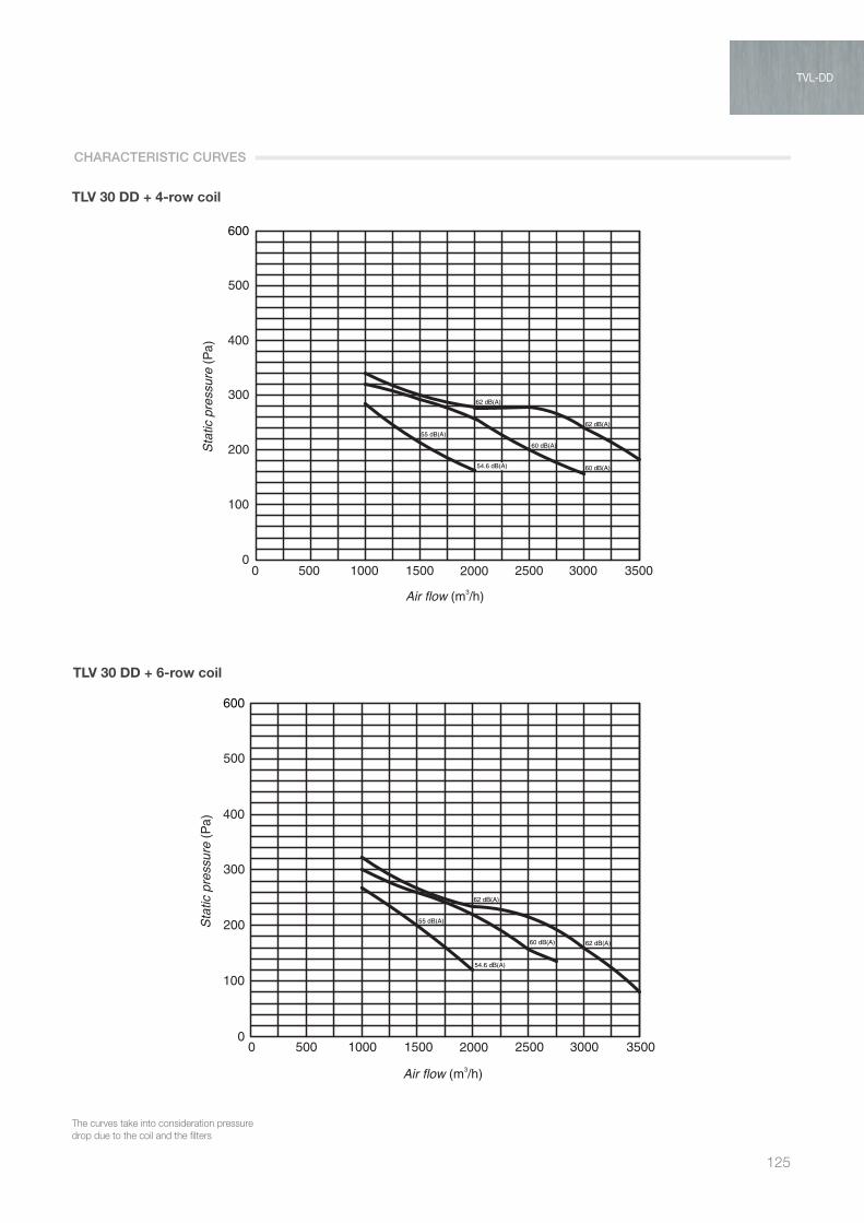
125
TLV 30 DD + 4-row coil
TVL 10 + Batteria 2 Ranghi
0
50
100
150
200
250
Le curve tengono conto delle perdite di caricodovute alla batteria ed ai filtri
TVL 10 + Batteria 4 Ranghi
59.3 dB(A)
55.6 dB(A)
54.5 dB(A)
54 dB(A)
50.9 dB(A)
51.2 dB(A)
51.5 dB(A)
TVL 10 + Batteria 6 Ranghi
59.6 dB(A)
59.3 dB(A)
54 dB(A)
50.9 dB(A)
51.2 dB(A)
51.5 dB(A)
59.6 dB(A)
59.3 dB(A)
55.6 dB(A)50.9 dB(A)
51.2 dB(A)
51.5 dB(A)
56.4 dB(A)
57.2 dB(A)
TVL 15 + Batteria 2 ranghi
50
100
150
200
250
300
350
360
TVL 15 + Batteria 4 ranghi TVL 15 + Batteria 6 ranghi
TVL 20 + Batteria 2 ranghi TVL 20 + Batteria 4 ranghi TVL 20 + Batteria 6 ranghi
TVL 30 DD +2R TVL 30 DD +4R TVL 30 DD +6R
TVL 40DD+2R TVL 40DD+4R TVL 40DD+6R
62 dB(A)
62 dB(A)
64 dB(A)
60 dB(A)
54 dB(A)
55 dB(A)
62 dB(A)
62 dB(A)
64 dB(A)
59 dB(A)
60 dB(A)
55 dB(A)
54 dB(A)
62 dB(A)
64 dB(A)
62.2 dB(A)
59.2 dB(A)
60 dB(A)
54 dB(A)
64.5 dB(A)
65.5 dB(A)
65.5 dB(A)
61.2 dB(A)
60 dB(A) 65.5 dB(A)
64.5 dB(A)
65.5 dB(A)
61.2 dB(A)
60 dB(A)
65.5 dB(A)
64.5 dB(A)
65.5 dB(A)
60 dB(A)
61.2 dB(A)
62 dB(A)
60 dB(A)
55 dB(A)
62 dB(A)
62 dB(A)
60 dB(A)
60 dB(A)
55 dB(A)
62 dB(A)
62 dB(A)60 dB(A)
55 dB(A)
0 400 600 800 1000 1200 14000
50
100
150
200
250
0 400 600 800 1000 1200 14000
50
100
150
200
250
0 400 600 800 1000 1200 1400
0 400 800 1200 1600 2000 2400 0 400 800 1200 1600 2000 240050
100
150
200
250
300
350
360
50
100
150
200
250
300
350
360
0 400 800 1200 1600 2000 2400
62 dB(A)
50
100
150
200
250
300
350
360
0 400 800 1200 1600 2000 240050
100
150
200
250
300
350
360
0 400 800 1200 1600 2000 240050
100
150
200
250
300
350
360
0 400 800 1200 1600 2000 2400
600
500
400
300
200
100
00 500 1000 1500 2000 2500 3000 3500
60 dB(A)
62 dB(A)
600
500
400
300
200
100
00 500 1000 1500 2000 2500 3000 3500
600
500
400
300
200
100
00 500 1000 1500 2000 2500 3000 3500
400
350
300
250
200
150
100
50
00 1000 2000 3000 4000 5000
400
350
300
250
200
150
100
50
00 1000 2000 3000 4000 5000
400
350
300
250
200
150
100
50
00 1000 2000 3000 4000 5000
Air flow (m3/h) Air flow (m3/h) Air flow (m3/h)
Air flow (m3/h) Air flow (m3/h)Air flow (m3/h)
Air flow (m3/h) Air flow (m3/h) Air flow (m3/h)
Air flow (m3/h) Air flow (m3/h) Air flow (m3/h)
Air flow (m3/h) Air flow (m3/h)Air flow (m3/h)
Stat
ic p
ress
ure
(Pa)
Stat
ic p
ress
ure
(Pa)
Stat
ic p
ress
ure
(Pa)
Stat
ic p
ress
ure
(Pa)
Stat
ic p
ress
ure
(Pa)
Stat
ic p
ress
ure
(Pa)
Stat
ic p
ress
ure
(Pa)
Stat
ic p
ress
ure
(Pa)
Stat
ic p
ress
ure
(Pa)
Stat
ic p
ress
ure
(Pa)
Stat
ic p
ress
ure
(Pa)
Stat
ic p
ress
ure
(Pa)
Stat
ic p
ress
ure
(Pa)
Stat
ic p
ress
ure
(Pa)
Stat
ic p
ress
ure
(Pa)
53 dB(A)
61 dB(A)
64 dB(A)
65 dB(A)
53 dB(A)
61 dB(A)
64 dB(A)
65 dB(A)
53 dB(A)
61 dB(A)65 dB(A)
64 dB(A)
54.6 dB(A)
54.6 dB(A)
54.6 dB(A)
59.6 dB(A)
55.6 dB(A)
54.5 dB(A)
The curves take into consideration pressure drop due to the coil and the filters
TLV 30 DD + 6-row coil
CHARACTERISTIC CURVES
TVL-DD
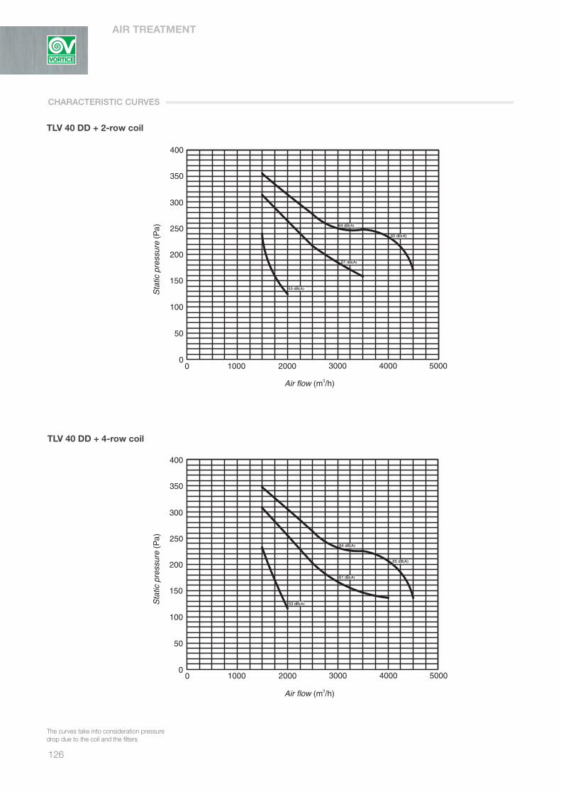
AIR TREATMENT
126
TLV 40 DD + 2-row coil
TVL 10 + Batteria 2 Ranghi
0
50
100
150
200
250
Le curve tengono conto delle perdite di caricodovute alla batteria ed ai filtri
TVL 10 + Batteria 4 Ranghi
59.3 dB(A)
55.6 dB(A)
54.5 dB(A)
54 dB(A)
50.9 dB(A)
51.2 dB(A)
51.5 dB(A)
TVL 10 + Batteria 6 Ranghi
59.6 dB(A)
59.3 dB(A)
54 dB(A)
50.9 dB(A)
51.2 dB(A)
51.5 dB(A)
59.6 dB(A)
59.3 dB(A)
55.6 dB(A)50.9 dB(A)
51.2 dB(A)
51.5 dB(A)
56.4 dB(A)
57.2 dB(A)
TVL 15 + Batteria 2 ranghi
50
100
150
200
250
300
350
360
TVL 15 + Batteria 4 ranghi TVL 15 + Batteria 6 ranghi
TVL 20 + Batteria 2 ranghi TVL 20 + Batteria 4 ranghi TVL 20 + Batteria 6 ranghi
TVL 30 DD +2R TVL 30 DD +4R TVL 30 DD +6R
TVL 40DD+2R TVL 40DD+4R TVL 40DD+6R
62 dB(A)
62 dB(A)
64 dB(A)
60 dB(A)
54 dB(A)
55 dB(A)
62 dB(A)
62 dB(A)
64 dB(A)
59 dB(A)
60 dB(A)
55 dB(A)
54 dB(A)
62 dB(A)
64 dB(A)
62.2 dB(A)
59.2 dB(A)
60 dB(A)
54 dB(A)
64.5 dB(A)
65.5 dB(A)
65.5 dB(A)
61.2 dB(A)
60 dB(A) 65.5 dB(A)
64.5 dB(A)
65.5 dB(A)
61.2 dB(A)
60 dB(A)
65.5 dB(A)
64.5 dB(A)
65.5 dB(A)
60 dB(A)
61.2 dB(A)
62 dB(A)
60 dB(A)
55 dB(A)
62 dB(A)
62 dB(A)
60 dB(A)
60 dB(A)
55 dB(A)
62 dB(A)
62 dB(A)60 dB(A)
55 dB(A)
0 400 600 800 1000 1200 14000
50
100
150
200
250
0 400 600 800 1000 1200 14000
50
100
150
200
250
0 400 600 800 1000 1200 1400
0 400 800 1200 1600 2000 2400 0 400 800 1200 1600 2000 240050
100
150
200
250
300
350
360
50
100
150
200
250
300
350
360
0 400 800 1200 1600 2000 2400
62 dB(A)
50
100
150
200
250
300
350
360
0 400 800 1200 1600 2000 240050
100
150
200
250
300
350
360
0 400 800 1200 1600 2000 240050
100
150
200
250
300
350
360
0 400 800 1200 1600 2000 2400
600
500
400
300
200
100
00 500 1000 1500 2000 2500 3000 3500
60 dB(A)
62 dB(A)
600
500
400
300
200
100
00 500 1000 1500 2000 2500 3000 3500
600
500
400
300
200
100
00 500 1000 1500 2000 2500 3000 3500
400
350
300
250
200
150
100
50
00 1000 2000 3000 4000 5000
400
350
300
250
200
150
100
50
00 1000 2000 3000 4000 5000
400
350
300
250
200
150
100
50
00 1000 2000 3000 4000 5000
Air flow (m3/h) Air flow (m3/h) Air flow (m3/h)
Air flow (m3/h) Air flow (m3/h)Air flow (m3/h)
Air flow (m3/h) Air flow (m3/h) Air flow (m3/h)
Air flow (m3/h) Air flow (m3/h) Air flow (m3/h)
Air flow (m3/h) Air flow (m3/h)Air flow (m3/h)
Stat
ic p
ress
ure
(Pa)
Stat
ic p
ress
ure
(Pa)
Stat
ic p
ress
ure
(Pa)
Stat
ic p
ress
ure
(Pa)
Stat
ic p
ress
ure
(Pa)
Stat
ic p
ress
ure
(Pa)
Stat
ic p
ress
ure
(Pa)
Stat
ic p
ress
ure
(Pa)
Stat
ic p
ress
ure
(Pa)
Stat
ic p
ress
ure
(Pa)
Stat
ic p
ress
ure
(Pa)
Stat
ic p
ress
ure
(Pa)
Stat
ic p
ress
ure
(Pa)
Stat
ic p
ress
ure
(Pa)
Stat
ic p
ress
ure
(Pa)
53 dB(A)
61 dB(A)
64 dB(A)
65 dB(A)
53 dB(A)
61 dB(A)
64 dB(A)
65 dB(A)
53 dB(A)
61 dB(A)65 dB(A)
64 dB(A)
54.6 dB(A)
54.6 dB(A)
54.6 dB(A)
59.6 dB(A)
55.6 dB(A)
54.5 dB(A)
The curves take into consideration pressure drop due to the coil and the filters
TLV 40 DD + 4-row coil
CHARACTERISTIC CURVES
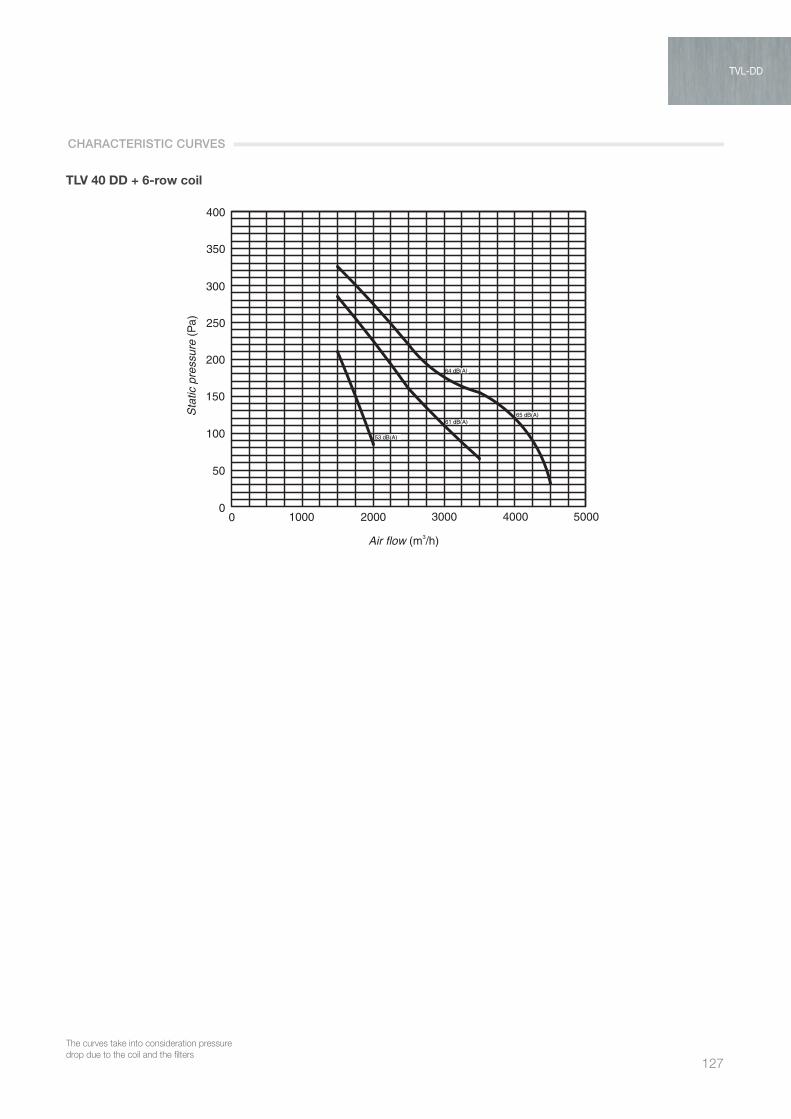
127
TLV 40 DD + 6-row coil
TVL 10 + Batteria 2 Ranghi
0
50
100
150
200
250
Le curve tengono conto delle perdite di caricodovute alla batteria ed ai filtri
TVL 10 + Batteria 4 Ranghi
59.3 dB(A)
55.6 dB(A)
54.5 dB(A)
54 dB(A)
50.9 dB(A)
51.2 dB(A)
51.5 dB(A)
TVL 10 + Batteria 6 Ranghi
59.6 dB(A)
59.3 dB(A)
54 dB(A)
50.9 dB(A)
51.2 dB(A)
51.5 dB(A)
59.6 dB(A)
59.3 dB(A)
55.6 dB(A)50.9 dB(A)
51.2 dB(A)
51.5 dB(A)
56.4 dB(A)
57.2 dB(A)
TVL 15 + Batteria 2 ranghi
50
100
150
200
250
300
350
360
TVL 15 + Batteria 4 ranghi TVL 15 + Batteria 6 ranghi
TVL 20 + Batteria 2 ranghi TVL 20 + Batteria 4 ranghi TVL 20 + Batteria 6 ranghi
TVL 30 DD +2R TVL 30 DD +4R TVL 30 DD +6R
TVL 40DD+2R TVL 40DD+4R TVL 40DD+6R
62 dB(A)
62 dB(A)
64 dB(A)
60 dB(A)
54 dB(A)
55 dB(A)
62 dB(A)
62 dB(A)
64 dB(A)
59 dB(A)
60 dB(A)
55 dB(A)
54 dB(A)
62 dB(A)
64 dB(A)
62.2 dB(A)
59.2 dB(A)
60 dB(A)
54 dB(A)
64.5 dB(A)
65.5 dB(A)
65.5 dB(A)
61.2 dB(A)
60 dB(A) 65.5 dB(A)
64.5 dB(A)
65.5 dB(A)
61.2 dB(A)
60 dB(A)
65.5 dB(A)
64.5 dB(A)
65.5 dB(A)
60 dB(A)
61.2 dB(A)
62 dB(A)
60 dB(A)
55 dB(A)
62 dB(A)
62 dB(A)
60 dB(A)
60 dB(A)
55 dB(A)
62 dB(A)
62 dB(A)60 dB(A)
55 dB(A)
0 400 600 800 1000 1200 14000
50
100
150
200
250
0 400 600 800 1000 1200 14000
50
100
150
200
250
0 400 600 800 1000 1200 1400
0 400 800 1200 1600 2000 2400 0 400 800 1200 1600 2000 240050
100
150
200
250
300
350
360
50
100
150
200
250
300
350
360
0 400 800 1200 1600 2000 2400
62 dB(A)
50
100
150
200
250
300
350
360
0 400 800 1200 1600 2000 240050
100
150
200
250
300
350
360
0 400 800 1200 1600 2000 240050
100
150
200
250
300
350
360
0 400 800 1200 1600 2000 2400
600
500
400
300
200
100
00 500 1000 1500 2000 2500 3000 3500
60 dB(A)
62 dB(A)
600
500
400
300
200
100
00 500 1000 1500 2000 2500 3000 3500
600
500
400
300
200
100
00 500 1000 1500 2000 2500 3000 3500
400
350
300
250
200
150
100
50
00 1000 2000 3000 4000 5000
400
350
300
250
200
150
100
50
00 1000 2000 3000 4000 5000
400
350
300
250
200
150
100
50
00 1000 2000 3000 4000 5000
Air flow (m3/h) Air flow (m3/h) Air flow (m3/h)
Air flow (m3/h) Air flow (m3/h)Air flow (m3/h)
Air flow (m3/h) Air flow (m3/h) Air flow (m3/h)
Air flow (m3/h) Air flow (m3/h) Air flow (m3/h)
Air flow (m3/h) Air flow (m3/h)Air flow (m3/h)
Stat
ic p
ress
ure
(Pa)
Stat
ic p
ress
ure
(Pa)
Stat
ic p
ress
ure
(Pa)
Stat
ic p
ress
ure
(Pa)
Stat
ic p
ress
ure
(Pa)
Stat
ic p
ress
ure
(Pa)
Stat
ic p
ress
ure
(Pa)
Stat
ic p
ress
ure
(Pa)
Stat
ic p
ress
ure
(Pa)
Stat
ic p
ress
ure
(Pa)
Stat
ic p
ress
ure
(Pa)
Stat
ic p
ress
ure
(Pa)
Stat
ic p
ress
ure
(Pa)
Stat
ic p
ress
ure
(Pa)
Stat
ic p
ress
ure
(Pa)
53 dB(A)
61 dB(A)
64 dB(A)
65 dB(A)
53 dB(A)
61 dB(A)
64 dB(A)
65 dB(A)
53 dB(A)
61 dB(A)65 dB(A)
64 dB(A)
54.6 dB(A)
54.6 dB(A)
54.6 dB(A)
59.6 dB(A)
55.6 dB(A)
54.5 dB(A)
The curves take into consideration pressure drop due to the coil and the filters
CHARACTERISTIC CURVES
TVL-DD

AIR TREATMENT
128
HRLHigh efficiency units
PRODUCT SPECIFICATIONS KEY FEATURES
The HRL high efficiency energy recovery units are wdesigned for systems operating with 100% outside air, bringing cost savings while at the same time guaranteeing excellent air-conditioning performance in environments such as schools, offices, banks, swimming pools and public premises. Their main feature is the use of two static heat recovery
units in series, made from aluminium or coated aluminium, ensuring significant savings in running costs by recovering energy that would otherwise be lost as heat, with efficiency exceeding 90%. There are 7 models, with range of flow-rates from
1,000 m3/h to 15,000 m3/h, offering extremely simple installation and flexibility. This series uses centrifugal fans directly coupled to the
latest generation EC motors.
Base: made from thick press formed galvanised sheet metal longitudinal members. These are fastened to the four sides of each section, with the unit resting on the ground on the shorter sides. Each base comes complete with suitably sized holes for inserting lifting bars. The type wof section bars and the thickness of the sheet metal used ensure high structural rigidity during transport and safety when handling on site. Frame: frame made using a modular system of extruded
anodised aluminium alloy section bars (in accordance with UNI 9006/1), joined by die-cast aluminium corners. Sandwich panels: sandwich panels, insulated with
polyurethane foam, density 40 kg/m, 48 mm thick. Construction:
OUTSIDE SHELL Coated sheet metal (EN 10169) Hot galvanised steel base: reference standard EN 10327,
Z100 coating. Standard protection involves application of a 25 micron dry film (tolerance ± 3 mm) on the top face and a 7/10 micron dry film on the bottom face, in accordance with EN 13523.
Specifications: - Gloss 30/35 - Condensation resistance 1000 h no blistering

129
- Resistance to salt spray 360 h no blistering - Resistance to fluorescent UV light and water condensation
2000 h UVA residual gloss 50% no blistering - Min. surface hardness F - Thicknesses available 6/10 mm INSIDE SHELL Galvanised sheet metal DXD51-Z200 galvanised rolled sheet for cold forming and
stamping (EN 10142). 6/10 mm thick. Specially treated sheet metal available on request, such as Peraluman or AISI 304/316 stainless steel.
Heat recovery units: static heat recovery units featuring plate heat exchangers, cross flow and counterflow units. The use of these units brings significant savings in the running costs of air-conditioning systems by recovering energy that would otherwise be lost as heat. These units are made from aluminium or coated aluminium for aggressive environments . Efficiency exceeding 90%.
Middle efficiency filters: middle efficiency or coarse filters are used as the first or second filter stage.
Filter class in accordance with EN 779-2002: G2 Weighted average efficiency ≥ 65% G3 Weighted average efficiency ≥ 80% G4 Weighted average efficiency ≥ 90%
Type of filters G2 Corrugated mesh filter cells (stainless/galvanised steel) G3 Drum filter with progressive density synthetic media G4 Corrugated filter cells with synthetic media, galvanised
steel frame, welded galvanised steel wire protective grill.
High efficiency filters: high efficiency filters or fine filters are used as the second or final filter stage in places without specific needs. Also used as pre-filters for HEPA / ULPA.
Filter class in accordance with EN 779-2002: F5 Average dust spot efficiency ≥ 40% F6 Average dust spot efficiency ≥ 60% F7 Average dust spot efficiency ≥ 80% F8 Average dust spot efficiency ≥ 90% F9 Average dust spot efficiency ≥ 95%
Type of filters F5 - Corrugated filter cells with synthetic media, galvanised
steel frame, welded galvanised steel wire protective grill. Recommended maximum pressure drop 200 Pa - Soft pocket filters with large glass fibre filtering surface. Galvanised steel frame. Recommended maximum pressure drop 250 Pa F6 / F7 / F9 (fig. 2)
- Soft pocket filters with large glass fibre filtering surface. Galvanised steel frame Length 380 mm Upon request the filtering surface area can be increased
by extending the length of the filter to 535 or 635 mm Recommended pressure drop 250 Pa - Rigid glass fibre pocket filter, polypropylene/ABS frame. Recommended maximum pressure drop 250 Pa (fig. 1)
Fan: impeller with 7 backward curved blades. Aluminium impellers, diameter 250 to 560. Driven by premium energy efficient motor with integrated EC technology.
Features and specifications: High power density, wide range with high efficiency, low
noise levels. The technical advantages of these high effi-ciency centrifugal impellers are due to their construction, with optimised rotating diffuser.
- Index of protection IP 54 - Insulation class F - Thermal class 155 - Max room temperature 60°C
fig. 2
TVL-DDHRL
fig. 1

AIR TREATMENT
130
Heat exchange coils are the principal elements bringing about changes in air temperature and humidity. Heat exchange is indirect; a primary fluid such as hot or cold
water, or hot or cold gas that flows through the coils interacts with the secondary fluid, in this case the process air.
The coils are finned tubes made from different materials with continuous fins featuring a collar to adjust and evenly space the fins.
The tubes are mechanically expanded to ensure perfect coupling between tube and fin and consequently perfect heat exchange.
The fins have a corrugated surface to ensure rigidity and create air turbulence, increasing the heat exchange coefficient.
All coils can be removed both from the side with fittings and the opposite side.
The heat exchanger construction materials are chosen based on the primary and secondary fluids; the following options are available:
Materials Copper tube Aluminium fins Copper tube Copper fins Copper tube Tinned copper fins Copper tube Coated aluminium fins Iron tube Aluminium fins Stainless steel tube Aluminium fins Stainless steel tube Stainless steel fins
Configurations PT 60 60x30 ø 5/8 tube PT 30 30x30 ø 5/8 tube PT 30 30x26 ø 3/8 tube PT 40 40x30 ø 5/8 tube Fin pitch mm 1,8 2,0 2,5 3,0 4,0 5,0 6,0
Operation Hot water Cold water Superheated water Steam Direct expansion of Freon Condensation of Freon
The number of rows, circuit configuration and materials can be easily determined using the VORTICE selection program and with the help of the company’s technical department.
When sizing the unit, as well as air velocity, a number of minimum and maximum limits also been to be taken into account, based on experience and practical considerations.
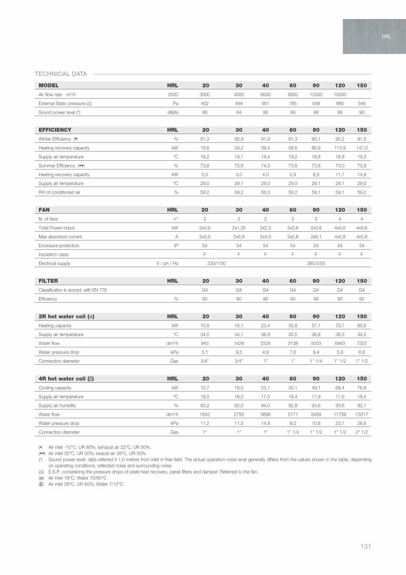
131
HRL
MODEL HRL 20 30 40 60 90 120 150
Air flow rate m3/h 2000 3000 4000 6000 9000 12000 15000
External Static pressure (∆) Pa 402 494 951 785 548 860 546
Sound power level (*) dB(A) 86 84 86 89 88 89 90
EFFICIENCY HRL 20 30 40 60 90 120 150
Winter Efficiency (▪) % 91,3 90,9 91,9 91,3 90,1 90,2 91,5
Heating recovery capacity kW 19,6 29,2 39,4 58,6 86,9 115,9 147,0
Supply air temperature °C 19,2 19,1 19,4 19,2 18,8 18,8 19,3
Summer Efficiency (••) % 73,8 73,6 74,3 73,8 73,8 73,0 73,9
Heating recovery capacity kW 2,0 3,0 4,0 5,9 8,9 11,7 14,8
Supply air temperature °C 29,0 29,1 29,0 29,0 29,1 29,1 29,0
RH of conditioned air % 59,2 59,2 59,3 59,2 59,1 59,1 59,2
FAN HRL 20 30 40 60 90 120 150
N. of fans n° 2 2 2 2 2 4 4
Total Power imput kW 2x0,9 2x1,35 2x2,5 2x3,6 2x3,8 4x3,6 4x3,6
Max absorbed current A 2x3,9 2x6,9 2x4,0 2x5,8 2x6,1 4x5,8 4x5,8
Enclosure protection IP 54 54 54 54 54 54 54
Insulation class F F F F F F F
Electrical supply V / ph / Hz 220/1/50 380/3/50
FILTER HRL 20 30 40 60 90 120 150
Classification in accord. with EN 779 G4 G4 G4 G4 G4 G4 G4
Efficiency % 90 90 90 90 90 90 90
2R hot water coil (α) HRL 20 30 40 60 90 120 150
Heating capacity kW 10,8 16,1 23,4 35,8 57,1 73,7 85,6
Supply air temperature °C 34,0 34,1 36,8 35,5 36,8 36,3 34,5
Water flow dm3/h 943 1428 2224 3138 5003 6463 7322
Water pressure drop kPa 5,1 9,5 4,9 7,6 9,4 5,9 6,8
Connection diameter Gas 3/4” 3/4” 1” 1” 1” 1/4 1” 1/2 1” 1/2
4R hot water coil (β) HRL 20 30 40 60 90 120 150
Cooling capacity kW 10,7 16,0 23,1 30,1 49,1 68,4 76,9
Supply air temperature °C 18,0 18,0 17,5 18,4 17,9 17,6 18,4
Supply air humidity % 93,2 93,0 94,0 92,8 93,6 93,6 92,1
Water flow dm3/h 1842 2793 3698 5171 8439 11759 13217
Water pressure drop kPa 11,2 11,5 14,8 8,0 10,8 23,1 28,6
Connection diameter Gas 1” 1” 1” 1” 1/4 1” 1/2 1” 1/2 2” 1/2
(▪ ) Air inlet -10°C, UR 80%; exhaust air 22°C, UR 50%.(••) Air inlet 32°C, UR 50%; exaust air 28°C, UR 50%.(*) Sound power level: data referred ti 1,0 metres from inlet in free field. The actual operation noise level generally differs from the values shown in the table, depending
on operating conditions, reflected noise and surrounding noise.(∆) E.S.P. considering the pressure drops of plate heat recovery, panel filters and damper/ Referred to the fan.(α) Air inlet 18°C; Water 70/60°C(β) Air inlet 28°C, UR 60%; Water 7/12°C
TECHNICAL DATA
HRL
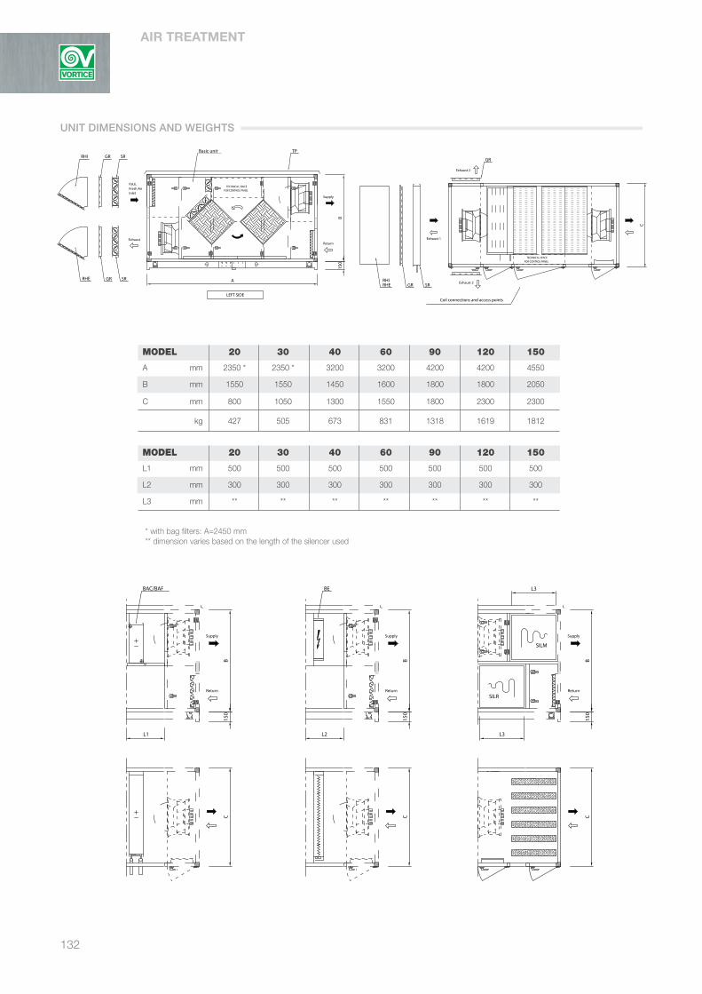
AIR TREATMENT
132
ART
ART
FOR CONTROL PANELTECHNICAL SPACE
ART
ART
Coil connections and access points
Fresh Air P.A.E.
Return
Supply
Exhaust 2
FOR CONTROL PANELTECHNICAL SPACE
ART
Return
Supply
ART
ART
Return
Supply
ART
Inlet
BEBAC/BAF
Exhaust
RHITP
ART
Return
Supply
SILM
ART
Basic unitGR
GRRHE
SILR
Exhaust 1
Exhaust 2GR
SR
SR
SRRHERHI
GR
LEFT SIDE
RIGHT SIDE
C
C C C
A
150
B
L1
150
L2
B
150
L3
B
150
B
L3
ART
ART
FOR CONTROL PANELTECHNICAL SPACE
ART
ART
Coil connections and access points
Fresh Air P.A.E.
Return
Supply
Exhaust 2
FOR CONTROL PANELTECHNICAL SPACE
ART
Return
Supply
ART
ART
Return
Supply
ART
Inlet
BEBAC/BAF
Exhaust
RHITP
ART
Return
Supply
SILM
ART
Basic unitGR
GRRHE
SILR
Exhaust 1
Exhaust 2GR
SR
SR
SRRHERHI
GR
LEFT SIDE
RIGHT SIDE
C
C C C
A
150
B
L1
150
L2
B
150
L3
B
150
B
L3
MODEL 20 30 40 60 90 120 150
A mm 2350 * 2350 * 3200 3200 4200 4200 4550
B mm 1550 1550 1450 1600 1800 1800 2050
C mm 800 1050 1300 1550 1800 2300 2300
kg 427 505 673 831 1318 1619 1812
MODEL 20 30 40 60 90 120 150
L1 mm 500 500 500 500 500 500 500
L2 mm 300 300 300 300 300 300 300
L3 mm ** ** ** ** ** ** **
* with bag filters: A=2450 mm** dimension varies based on the length of the silencer used
ART
ART
FOR CONTROL PANELTECHNICAL SPACE
ART
ART
Coil connections and access points
Fresh Air P.A.E.
Return
Supply
Exhaust 2
FOR CONTROL PANELTECHNICAL SPACE
ART
Return
Supply
ART
ART
Return
Supply
ART
Inlet
BEBAC/BAF
Exhaust
RHITP
ART
Return
Supply
SILM
ART
Basic unitGR
GRRHE
SILR
Exhaust 1
Exhaust 2GR
SR
SR
SRRHERHI
GR
LEFT SIDE
RIGHT SIDE
C
C C C
A
150
B
L1
150
L2
B
150
L3
B
150
BL3
Frequency (Hz) 63 125 250 500 1000 2000 4000 8000
Silencers Lenght [L3] 700 mm 6 10 14 23 32 26 20 15
950 mm 9 14 25 42 39 37 31 21
UNIT DIMENSIONS AND WEIGHTS

133
HRL
* with bag filters: A=2450 mm** dimension varies based on the length of the silencer used
BAC/BAF Heating/cooling coil.BE Electric coil with tubular heater and three-phase power supply.SILR Intake silencer (dimensions available: length 700 / 950 mm).SILM Outlet silencer (dimensions available: length 700 / 950 mm).TP Coated sheet metal rain cover.SR Control damper with motor drive shaft.GR Grill with fixed aluminium blades.RHI Rain hood on fresh air inlet made from galvanised sheet metal with bird netting.RHE Rain hood on exhaust air outlet made from galvanised sheet metal with bird netting.MS Safety microswitch.
Frequency (Hz) 63 125 250 500 1000 2000 4000 8000
Silencers Lenght [L3] 700 mm 6 10 14 23 32 26 20 15
950 mm 9 14 25 42 39 37 31 21
AVAILABLE ACCESSORIES
HRL
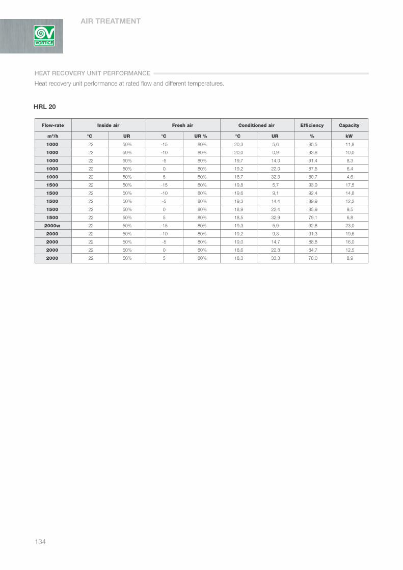
AIR TREATMENT
134
HRL 20
22 50% -15 80% 20,3 5,6 95,5 11,8
22 50% -10 80% 20,0 0,9 93,8 10,0
22 50% -5 80% 19,7 14,0 91,4 8,3
22 50% 0 80% 19,2 22,0 87,5 6,4
22 50% 5 80% 18,7 32,3 80,7 4,6
22 50% -15 80% 19,8 5,7 93,9 17,5
22 50% -10 80% 19,6 9,1 92,4 14,8
22 50% -5 80% 19,3 14,4 89,9 12,2
22 50% 0 80% 18,9 22,4 85,9 9,5
22 50% 5 80% 18,5 32,9 79,1 6,8
22 50% -15 80% 19,3 5,9 92,8 23,0
22 50% -10 80% 19,2 9,3 91,3 19,6
22 50% -5 80% 19,0 14,7 88,8 16,0
22 50% 0 80% 18,6 22,8 84,7 12,5
22 50% 5 80% 18,3 33,3 78,0 8,9
Flow-rate Inside air Fresh air Conditioned air Efficiency Capacity
m3/h °C UR °C UR % °C UR % kW
1000
1000
1000
1000
1000
1500
1500
1500
1500
1500
2000w
2000
2000
2000
2000
HEAT RECOVERY UNIT PERFORMANCE
Heat recovery unit performance at rated flow and different temperatures.
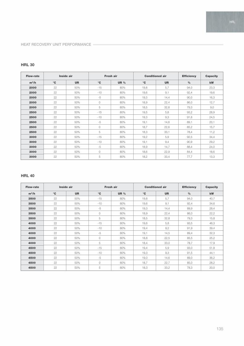
135
HRL 30
22 50% -15 80% 19,8 5,7 94,0 23,3
22 50% -10 80% 19,6 9,1 92,4 19,6
22 50% -5 80% 19,3 14,4 90,0 16,3
22 50% 0 80% 18,9 22,4 86,0 12,7
22 50% 5 80% 18,5 32,8 79,3 9,0
22 50% -15 80% 19,5 5,8 93,2 28,9
22 50% -10 80% 19,3 9,3 91,6 24,5
22 50% -5 80% 19,1 14,6 89,1 20,1
22 50% 0 80% 18,7 22,6 85,2 15,7
22 50% 5 80% 18,3 33,1 78,4 11,2
22 50% -15 80% 19,2 5,9 92,5 34,4
22 50% -10 80% 19,1 9,4 90,9 29,2
22 50% -5 80% 18,9 14,7 88,4 24,0
22 50% 0 80% 18,6 22,9 84,4 18,6
22 50% 5 80% 18,2 33,4 77,7 13,3
Flow-rate Inside air Fresh air Conditioned air Efficiency Capacity
m3/h °C UR °C UR % °C UR % kW
2000
2000
2000
2000
2000
2500
2500
2500
2500
2500
3000
3000
3000
3000
3000
22 50% -15 80% 19,8 5,7 94,0 40,7
22 50% -10 80% 19,6 9,1 92,4 34,6
22 50% -5 80% 19,3 14,4 89,9 28,4
22 50% 0 80% 18,9 22,4 86,0 22,2
22 50% 5 80% 18,5 32,8 79,3 15,8
22 50% -15 80% 19,6 5,8 93,5 46,3
22 50% -10 80% 19,4 9,2 91,9 39,4
22 50% -5 80% 19,1 14,5 89,4 32,3
22 50% 0 80% 18,8 22,5 85,5 25,2
22 50% 5 80% 18,4 33,0 78,7 17,9
22 50% -15 80% 19,4 5,9 93,0 51,8
22 50% -10 80% 19,3 9,3 91,5 44,1
22 50% -5 80% 19,0 14,6 89,0 36,2
22 50% 0 80% 18,7 22,7 85,0 28,2
22 50% 5 80% 18,3 33,2 78,3 20,0
Flow-rate Inside air Fresh air Conditioned air Efficiency Capacity
m3/h °C UR °C UR % °C UR % kW
3500
3500
3500
3500
3500
4000
4000
4000
4000
4000
4500
4500
4500
4500
4500
HRL 40
HEAT RECOVERY UNIT PERFORMANCE
HRL

AIR TREATMENT
136
HRL 60
22 50% -15 80% 19,6 5,8 93,5 57,9
22 50% -10 80% 19,4 9,2 91,9 49,2
22 50% -5 80% 19,2 14,5 89,5 40,4
22 50% 0 80% 18,8 22,5 95,5 31,5
22 50% 5 80% 18,4 33,0 78,7 22,4
22 50% -15 80% 19,5 5,8 93,2 63,5
22 50% -10 80% 19,3 9,3 91,6 53,9
22 50% -5 80% 19,0 14,6 89,1 44,3
22 50% 0 80% 18,7 22,6 85,2 34,5
22 50% 5 80% 18,3 33,1 78,4 24,5
22 50% -15 80% 19,3 5,9 92,8 69,0
22 50% -10 80% 19,2 9,3 91,3 58,6
22 50% -5 80% 19,0 14,7 88,7 48,1
22 50% 0 80% 18,6 22,8 84,7 37,4
22 50% 5 80% 18,3 33,3 78,0 26,6
Flow-rate Inside air Fresh air Conditioned air Efficiency Capacity
m3/h °C UR °C UR % °C UR % kW
5000
5000
5000
5000
5000
5500
5500
5500
5500
5500
6000
6000
6000
6000
6000
22 50% -15 80% 19,7 5,8 93,7 81,2
22 50% -10 80% 19,5 9,2 92,1 69,1
22 50% -5 80% 19,2 14,4 89,6 56,7
22 50% 0 80% 18,8 22,5 85,6 44,1
22 50% 5 80% 18,4 32,9 78,9 31,4
22 50% -15 80% 19,3 5,9 92,6 91,8
22 50% -10 80% 19,1 9,4 91,0 78,0
22 50% -5 80% 18,9 14,7 88,5 64,0
22 50% 0 80% 18,6 22,8 84,6 49,8
22 50% 5 80% 18,2 33,4 77,8 35,4
22 50% -15 80% 18,9 6,0 91,7 102,2
22 50% -10 80% 18,8 9,6 90,1 86,9
22 50% -5 80% 18,6 15,0 87,6 71,2
22 50% 0 80% 18,4 23,1 83,6 55,4
22 50% 5 80% 18,1 33,7 76,9 39,4
Flow-rate Inside air Fresh air Conditioned air Efficiency Capacity
m3/h °C UR °C UR % °C UR % kW
7000
7000
7000
7000
7000
8000
8000
8000
8000
8000
9000
9000
9000
9000
9000
HRL 90
HEAT RECOVERY UNIT PERFORMANCE
Heat recovery unit performance at rated flow and different temperatures.

137
HRL 120
HRL 150
22 50% -15 80% 19,5 5,6 93,2 115,4
22 50% -10 80% 19,3 9,3 91,6 98,1
22 50% -5 80% 19,1 14,6 89,1 80,5
22 50% 0 80% 18,7 22,6 85,2 62,7
22 50% 5 80% 18,3 33,1 78,4 44,6
22 50% -15 80% 19,2 5,9 92,4 125,9
22 50% -10 80% 19,1 9,4 90,8 107,0
22 50% -5 80% 18,9 14,8 88,4 87,9
22 50% 0 80% 18,6 22,9 84,4 68,3
22 50% 5 80% 18,2 33,4 77,6 48,6
22 50% -15 80% 18,9 6,0 91,7 136,3
22 50% -10 80% 18,8 9,6 90,2 115,9
22 50% -5 80% 18,7 14,9 87,6 95,0
22 50% 0 80% 18,4 23,1 83,7 73,9
22 50% 5 80% 18,1 33,7 76,9 52,5
Flow-rate Inside air Fresh air Conditioned air Efficiency Capacity
m3/h °C UR °C UR % °C UR % kW
10000
10000
10000
10000
10000
11000
11000
11000
11000
11000
12000
12000
12000
12000
12000
22 50% -15 80% 19,8 5,7 94,1 151,5
22 50% -10 80% 19,6 9,1 92,6 128,9
22 50% -5 80% 19,3 14,3 90,1 105,9
22 50% 0 80% 19,0 22,3 86,2 82,5
22 50% 5 80% 18,5 32,8 79,4 58,7
22 50% -15 80% 19,6 5,8 93,5 162,2
22 50% -10 80% 19,4 9,2 91,9 137,9
22 50% -5 80% 19,2 14,5 89,5 113,3
22 50% 0 80% 18,8 22,5 85,6 88,2
22 50% 5 80% 18,4 33,0 78,8 62,7
22 50% -15 80% 19,4 5,9 93,0 172,8
22 50% -10 80% 19,3 9,3 91,5 147,0
22 50% -5 80% 19,0 14,6 89,0 120,6
22 50% 0 80% 18,7 22,7 85,0 93,5
22 50% 5 80% 18,3 33,2 78,3 64,8
Flow-rate Inside air Fresh air Conditioned air Efficiency Capacity
m3/h °C UR °C UR % °C UR % kW
13000
13000
13000
13000
13000
14000
14000
14000
14000
14000
15000
15000
15000
15000
15000
HRL
HEAT RECOVERY UNIT PERFORMANCE

AIR TREATMENT
138
HRL 20
28 50% 30 50% 28,5 54,6 75,7 0,5
28 50% 32 50% 29,0 59,6 75,7 1,0
28 50% 35 50% 29,7 67,4 75,7 1,8
26 50% 30 50% 27,0 59,6 75,7 1,0
26 50% 32 50% 27,5 64,9 75,7 1,5
26 50% 35 50% 28,2 73,6 75,7 2,3
28 50% 30 50% 28,5 54,5 74,6 0,7
28 50% 32 50% 29,0 59,3 74,6 1,5
28 50% 35 50% 29,8 67,1 74,6 2,6
26 50% 30 50% 27,0 59,5 74,6 1,5
26 50% 32 50% 27,5 64,7 74,6 2,2
26 50% 35 50% 28,3 73,2 74,6 3,4
28 50% 30 50% 28,5 54,4 73,8 1,0
28 50% 32 50% 29,0 59,2 73,8 2,0
28 50% 35 50% 29,8 66,9 73,8 3,5
26 50% 30 50% 27,0 59,3 73,8 2,0
26 50% 32 50% 27,6 64,5 73,8 3,0
26 50% 35 50% 28,4 72,9 73,8 4,4
Flow-rate Inside air Fresh air Conditioned air Efficiency Capacity
m3/h °C UR °C UR % °C UR % kW
1000
1000
1000
1000
1000
1000
1500
1500
1500
1500
1500
1500
2000
2000
2000
2000
2000
2000
28 50% 30 50% 28,5 54,5 74,7 1,0
28 50% 32 50% 29,0 59,3 74,7 2,0
28 50% 35 50% 29,8 67,1 74,7 3,5
26 50% 30 50% 27,0 59,5 74,7 2,0
26 50% 32 50% 27,5 64,7 74,7 3,0
26 50% 35 50% 28,3 73,2 74,7 4,5
28 50% 30 50% 28,5 54,5 74,1 1,2
28 50% 32 50% 29,0 59,2 74,1 2,5
28 50% 35 50% 29,8 67,0 74,1 4,3
26 50% 30 50% 27,0 59,4 74,1 2,5
26 50% 32 50% 27,6 64,6 74,1 3,7
26 50% 35 50% 28,3 73,0 74,1 5,6
28 50% 30 50% 28,5 54,4 73,6 1,5
28 50% 32 50% 29,1 59,2 73,6 3,0
28 50% 35 50% 29,9 66,8 73,6 5,2
26 50% 30 50% 27,1 59,3 73,6 3,0
26 50% 32 50% 27,6 64,4 73,6 4,4
26 50% 35 50% 28,4 72,8 73,6 6,6
Flow-rate Inside air Fresh air Conditioned air Efficiency Capacity
m3/h °C UR °C UR % °C UR % kW
2000
2000
2000
2000
2000
2000
2500
2500
2500
2500
2500
2500
3000
3000
3000
3000
3000
3000
HRL 30
HEAT RECOVERY UNIT PERFORMANCE - VERIFICATION IN COOLING MODE

139
HRL
HRL 40
HRL 60
28 50% 30 50% 28,5 54,5 74,6 1,7
28 50% 32 50% 29,0 59,3 74,6 3,5
28 50% 35 50% 29,8 67,1 74,6 6,1
26 50% 30 50% 27,0 59,5 74,6 3,5
26 50% 32 50% 27,5 64,7 74,6 5,2
26 50% 35 50% 28,3 73,2 74,6 7,9
28 50% 30 50% 28,5 54,9 74,3 2,0
28 50% 32 50% 29,0 59,3 74,3 4,0
28 50% 35 50% 29,8 67,0 74,3 7,0
26 50% 30 50% 27,0 59,4 74,3 4,0
26 50% 32 50% 27,5 64,6 74,3 6,0
26 50% 35 50% 28,3 73,0 74,3 9,0
28 50% 30 50% 28,5 54,5 74,0 2,2
28 50% 32 50% 29,0 59,5 74,0 4,5
28 50% 35 50% 29,8 66,9 74,0 7,8
26 50% 30 50% 27,0 59,4 74,0 4,5
26 50% 32 50% 27,6 64,5 74,0 6,7
26 50% 35 50% 28,3 72,9 74,0 10,0
Flow-rate Inside air Fresh air Conditioned air Efficiency Capacity
m3/h °C UR °C UR % °C UR % kW
3500
3500
3500
3500
3500
3500
4000
4000
4000
4000
4000
4000
4500
4500
4500
4500
4500
4500
28 50% 30 50% 28,5 54,5 74,3 2,5
28 50% 32 50% 29,0 59,3 74,3 5,0
28 50% 35 50% 29,8 67,0 74,3 8,7
26 50% 30 50% 27,0 59,4 74,3 5,0
26 50% 32 50% 27,5 64,6 74,3 7,5
26 50% 35 50% 28,3 73,1 74,3 11,2
28 50% 30 50% 28,5 54,5 74,0 2,7
28 50% 32 50% 29,0 59,2 74,0 5,5
28 50% 35 50% 29,8 67,0 74,0 9,5
26 50% 30 50% 27,0 59,4 74,0 5,5
26 50% 32 50% 27,6 64,6 74,0 8,2
26 50% 35 50% 28,3 73,0 74,0 12,3
28 50% 30 50% 28,5 54,0 73,8 3,0
28 50% 32 50% 29,0 59,2 73,8 5,9
28 50% 35 50% 29,8 66,9 73,8 10,4
26 50% 30 50% 27,0 59,3 73,5 5,9
26 50% 32 50% 27,6 64,5 73,8 8,9
26 50% 35 50% 28,4 72,9 73,8 13,3
Flow-rate Inside air Fresh air Conditioned air Efficiency Capacity
m3/h °C UR °C UR % °C UR % kW
5000
5000
5000
5000
5000
5000
5500
5500
5500
5500
5500
5500
6000
6000
6000
6000
6000
6000
HEAT RECOVERY UNIT PERFORMANCE - VERIFICATION IN COOLING MODE
HRL

AIR TREATMENT
140
HRL 90
28 50% 30 50% 28,5 54,5 74,4 2,5
28 50% 32 50% 29,0 59,3 74,4 5,0
28 50% 35 50% 29,8 67,1 74,4 8,7
26 50% 30 50% 27,0 59,4 74,4 5,0
26 50% 32 50% 27,5 64,6 74,4 7,5
26 50% 35 50% 28,3 73,1 74,4 11,2
28 50% 30 50% 28,5 54,7 74,0 2,7
28 50% 32 50% 29,1 59,2 74,0 5,5
28 50% 35 50% 29,8 66,9 74,0 9,5
26 50% 30 50% 27,1 59,3 74,0 5,5
26 50% 32 50% 27,6 64,5 74,0 8,2
26 50% 35 50% 28,4 72,8 74,0 12,3
28 50% 30 50% 28,5 54,4 73,8 5,3
28 50% 32 50% 29,1 59,1 73,8 8,9
28 50% 35 50% 29,9 66,7 73,8 13,3
26 50% 30 50% 27,1 59,2 73,8 5,9
26 50% 32 50% 27,6 64,3 73,8 8,9
26 50% 35 50% 28,4 72,6 73,8 13,3
Flow-rate Inside air Fresh air Conditioned air Efficiency Capacity
m3/h °C UR °C UR % °C UR % kW
7000
7000
7000
7000
7000
7000
8000
8000
8000
8000
8000
8000
9000
9000
9000
9000
9000
9000
28 50% 30 50% 28,5 54,5 74,1 5,0
28 50% 32 50% 29,0 59,2 74,1 9,5
28 50% 35 50% 29,8 67,0 74,1 17,4
26 50% 30 50% 27,0 59,4 74,1 9,9
26 50% 32 50% 27,6 64,6 74,1 14,9
26 50% 35 50% 28,9 73,0 74,1 22,3
28 50% 30 50% 28,5 54,4 73,5 5,4
28 50% 32 50% 29,1 59,2 73,5 10,8
28 50% 35 50% 29,9 66,8 73,5 18,9
26 50% 30 50% 27,1 59,3 73,5 10,8
26 50% 32 50% 27,6 64,4 73,5 16,2
26 50% 35 50% 28,4 72,8 73,5 24,4
28 50% 30 50% 28,5 54,4 73,0 5,9
28 50% 32 50% 29,1 59,1 73,0 11,7
28 50% 35 50% 29,9 66,7 73,0 20,5
26 50% 30 50% 27,1 59,2 73,0 11,7
26 50% 32 50% 27,6 64,3 73,0 17,6
26 50% 35 50% 28,4 72,6 73,0 26,4
Flow-rate Inside air Fresh air Conditioned air Efficiency Capacity
m3/h °C UR °C UR % °C UR % kW
10000
10000
10000
10000
10000
10000
11000
11000
11000
11000
11000
11000
12000
12000
12000
12000
12000
12000
HRL 120
HEAT RECOVERY UNIT PERFORMANCE - VERIFICATION IN COOLING MODE

141
HRL 150
28 50% 30 50% 28,5 54,5 74,7 6,5
28 50% 32 50% 29,0 59,3 74,7 13,0
28 50% 35 50% 29,8 67,2 74,7 22,8
26 50% 30 50% 27,0 59,5 74,7 13,0
26 50% 32 50% 27,5 64,7 74,7 19,5
26 50% 35 50% 28,3 73,2 74,7 29,3
28 50% 30 50% 28,8 54,3 77,2 6,7
28 50% 32 50% 29,1 59,9 77,2 13,4
28 50% 35 50% 30,0 66,3 77,2 23,5
26 50% 30 50% 27,1 59,1 77,2 13,4
26 50% 32 50% 27,7 64,0 77,2 20,2
26 50% 35 50% 28,5 72,1 77,2 30,2
28 50% 30 50% 28,5 54,5 73,9 7,4
28 50% 32 50% 29,0 59,2 73,9 14,8
28 50% 35 50% 29,8 64,9 73,9 26,0
26 50% 30 50% 27,0 59,4 73,9 14,8
26 50% 32 50% 27,6 64,5 73,9 22,3
26 50% 35 50% 28,9 72,9 73,9 33,9
Flow-rate Inside air Fresh air Conditioned air Efficiency Capacity
m3/h °C UR °C UR % °C UR % kW
13000
13000
13000
13000
13000
13000
14000
14000
14000
14000
14000
14000
15000
15000
15000
15000
15000
15000
HEAT RECOVERY UNIT PERFORMANCE - VERIFICATION IN COOLING MODE
HRL

AIR TREATMENT
142
HRL 20
1000
1000
1000
1000
1500
1500
1500
1500
2000
2000
2000
2000
Va T.i. T.u. Pot. Pw. Dp W T.u. Pot. Pw. Dp W m3/h °C °C kW dm3/h KPa °C kW dm3/h KPa
Air Water 70/60 Water 45/40
17,0 38,7 7,30 640 3,8 28,4 3,83 663 4,0
18,0 39,2 7,14 626 3,8 28,9 3,67 635 3,9
19,0 39,7 6,98 612 3,7 29,4 3,51 607 3,8
20,0 40,3 6,82 598 3,7 29,9 3,35 580 3,7
17,0 35,5 9,33 818 4,5 26,7 4,89 847 4,8
18,0 36,1 9,13 800 4,5 27,3 4,69 811 4,6
19,0 36,7 8,92 782 4,4 27,9 4,48 776 4,5
20,0 37,3 8,72 764 4,3 28,5 4,28 741 4,3
17,0 33,3 11,00 964 5,2 25,6 5,76 998 5,6
18,0 34,0 10,76 943 5,1 26,2 5,52 956 5,4
19,0 34,6 10,51 922 5,0 26,8 5,28 914 5,1
20,0 35,3 10,27 901 4,9 27,5 5,03 872 4,9
2000
2000
2000
2000
2500
2500
2500
2500
3000
3000
3000
3000
Va T.i. T.u. Pot. Pw. Dp W T.u. Pot. Pw. Dp W m3/h °C °C kW dm3/h KPa °C kW dm3/h KPa
Air Water 70/60 Water 45/40
17,0 36,6 13,18 1155 7,3 27,3 6,93 1200 8
18,0 37,2 12,9 1131 7,1 27,9 6,65 1151 7,6
19,0 37,7 12,6 1106 6,9 28,4 6,36 1101 7,2
20,0 38,3 12,3 1081 6,7 29 6,08 1052 6,8
17,0 34,8 15,02 1316 8,6 26,4 7,9 1368 9,5
18,0 35,5 14,7 1288 8,3 27 7,55 1311 8,9
19,0 36,1 14,4 1260 8,1 27,6 7,24 1254 8,4
20,0 36,7 14,1 1232 7,9 28,2 6,92 1198 8
17,0 33,5 16,55 1460 9,8 25,7 8,76 1516 11,3
18,0 34,1 16,09 1428 9,5 26,9 8,4 1454 10,4
19,0 34,8 15,9 1397 9,3 27,0 8,09 1391 9,7
20,0 35,4 15,6 1365 9,0 27,6 7,67 1398 9,1
HRL 30
3500
3500
3500
3500
4000
4000
4000
4000
4500
4500
4500
4500
Va T.i. T.u. Pot. Pw. Dp W T.u. Pot. Pw. Dp W m3/h °C °C kW dm3/h KPa °C kW dm3/h KPa
Air Water 70/60 Water 45/40
17,0 37,4 24 2103 4,7 27,6 12,55 2173 5
18,0 37,9 23,46 2057 4,6 28,2 12,02 2081 4,8
19,0 38,5 22,9 2010 4,5 28,8 11,49 1989 4,6
20,0 39,0 22,4 1964 44,0 29,3 10,96 1897 4,4
17,0 36,3 25,94 2274 5 27,1 13,6 2350 5,3
18,0 36,8 23,37 2224 4,9 27,6 13 2250 5,1
19,0 37,4 24,8 2173 4,8 28,2 12,42 2151 4,9
20,0 38,0 24,2 2123 4,7 28,8 11,84 2051 4,7
17,0 35,3 27,75 2433 5,3 26,6 14,52 2514 5,7
18,0 35,9 27,14 2379 5,2 27,2 13,9 2407 5,5
19,0 36,5 26,5 2325 5,1 27,8 13,28 2900 5,2
20,0 37,1 25,9 2271 5,0 28,4 12,66 2192 5
HRL 40
WATER COIL PERFORMANCE IN HEATING MODE
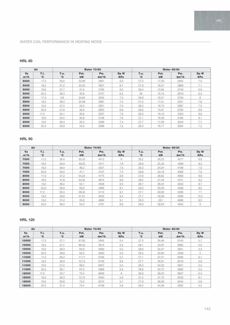
143
HRL 60
5000
5000
5000
5000
5500
5500
5500
5500
6000
6000
6000
6000
Va T.i. T.u. Pot. Pw. Dp W T.u. Pot. Pw. Dp W m3/h °C °C kW dm3/h KPa °C kW dm3/h KPa
Air Water 70/60 Water 45/40
17,0 36,6 32,98 2891 6,9 27,3 17,29 2954 7,5
18,0 37,2 32,25 2827 6,7 27,9 16,57 2869 7,1
19,0 37,7 31,5 2765 6,5 28,4 15,84 2743 6,8
20,0 38,3 30,8 2701 6,4 29 15,12 2619 6,4
17,0 3,8 34,84 3054 7,3 26,9 18,27 3163 8
18,0 36,4 34,08 2987 7,2 27,5 17,51 3031 7,6
19,0 37,0 33,3 2921 7,0 28,0 16,73 2897 7,2
20,0 37,6 32,6 2853 6,8 28,6 15,97 2765 6,8
17,0 35,1 36,6 3207 7,8 26,5 19,19 3323 8,6
18,0 35,5 35,8 3138 7,6 27,1 18,39 3184 8,1
19,0 36,3 35,0 3068 7,4 27,7 17,58 3043 7,7
20,0 36,9 34,2 2998 7,2 28,3 16,77 2904 7,2
HRL 90
7000
7000
7000
7000
8000
8000
8000
8000
9000
9000
9000
9000
Va T.i. T.u. Pot. Pw. Dp W T.u. Pot. Pw. Dp W m3/h °C °C kW dm3/h KPa °C kW dm3/h KPa
Air Water 70/60 Water 45/40
17,0 38,4 50,33 4412 8 28,2 26,23 4577 8,8
18,0 38,9 49,25 4317 7,8 28,8 25,35 4389 8,3
19,0 39,4 48,2 4221 7,6 29,3 24,24 4198 7,9
20,0 40,0 47,1 4127 7,4 29,8 23,16 4009 7,5
17,0 37,2 54,24 4774 8,8 27,6 28,62 4956 9,8
18,0 37,8 53,32 4674 8,6 28,2 27,44 4751 9,2
19,0 38,4 52,1 4508 8,3 28,7 26,24 4543 8,7
20,0 38,9 50,9 4465 8,1 29,3 25,05 4338 8,2
17,0 36,3 58,34 5114 9,7 27,1 30,65 5306 11
18,0 36,8 57,07 5003 9,4 27,7 29,38 5086 10,2
19,0 37,4 55,8 4894 9,1 28,3 28,1 4866 9,5
20,0 38,0 54,3 4781 8,8 28,9 26,63 4645 9
10000
10000
10000
10000
11000
11000
11000
11000
12000
12000
12000
12000
Va T.i. T.u. Pot. Pw. Dp W T.u. Pot. Pw. Dp W m3/h °C °C kW dm3/h KPa °C kW dm3/h KPa
Air Water 70/60 Water 45/40
17,0 37,1 67,82 5945 5,4 27,5 35,48 6143 5,7
18,0 37,7 66,33 5814 5,3 28,1 33,97 5882 5,5
19,0 38,3 64,8 5683 5,2 28,6 32,47 5621 5,3
20,0 38,8 63,3 5550 5,0 29,2 30,95 5359 5
17,0 36,4 71,71 6185 5,7 27,1 37,51 6495 6,1
18,0 36,9 70,12 6146 5,6 27,7 35,91 6218 5,8
19,0 37,5 68,5 6007 5,4 28,3 34,32 5941 5,5
20,0 38,1 67,0 5868 5,3 28,8 32,72 5664 5,3
17,0 35,7 75,4 6609 6 26,8 39,43 6827 6,4
18,0 36,3 73,73 6463 5,9 27,3 37,75 6535 6,1
19,0 36,8 72,0 6315 5,7 27,9 36,06 6244 5,8
20,0 37,4 70,4 6169 5,6 28,5 34,38 5952 5,5
HRL 120
WATER COIL PERFORMANCE IN HEATING MODE
HRL

AIR TREATMENT
144
HRL 150
13000
13000
13000
13000
14000
14000
14000
14000
15000
15000
15000
15000
Va T.i. T.u. Pot. Pw. Dp W T.u. Pot. Pw. Dp W m3/h °C °C kW dm3/h KPa °C kW dm3/h KPa
Air Water 70/60 Water 45/40
17,0 35 78,9 6914 6,3 26,4 41,16 7143 6,8
18,0 35,6 77,15 6763 6,2 27 39,5 6838 6,4
19,0 36,2 75,4 6609 6,0 27,8 37,73 6533 6,1
20,0 36,8 73,6 6455 6,0 28,2 35,97 6228 58,8
17,0 34,4 82,22 7207 6,6 26,1 43 7445 7,1
18,0 35,1 80,41 7049 6,5 26,7 41,16 7127 6,8
19,0 35,7 78,5 6888 6,3 27,3 39,32 6808 6,4
20,0 36,3 76,7 6727 6,1 28 37,49 6490 6,1
17,0 33,9 85,41 7487 6,9 25,9 44,67 7734 7,3
18,0 34,5 85,63 7322 6,8 26,5 42,75 7402 7,1
19,0 35,2 81,6 7154 6,6 27,1 40,85 7072 67,7
20,0 35,8 79,7 6986 6,1 27,7 38,93 6740 60
WATER COIL PERFORMANCE IN HEATING MODE
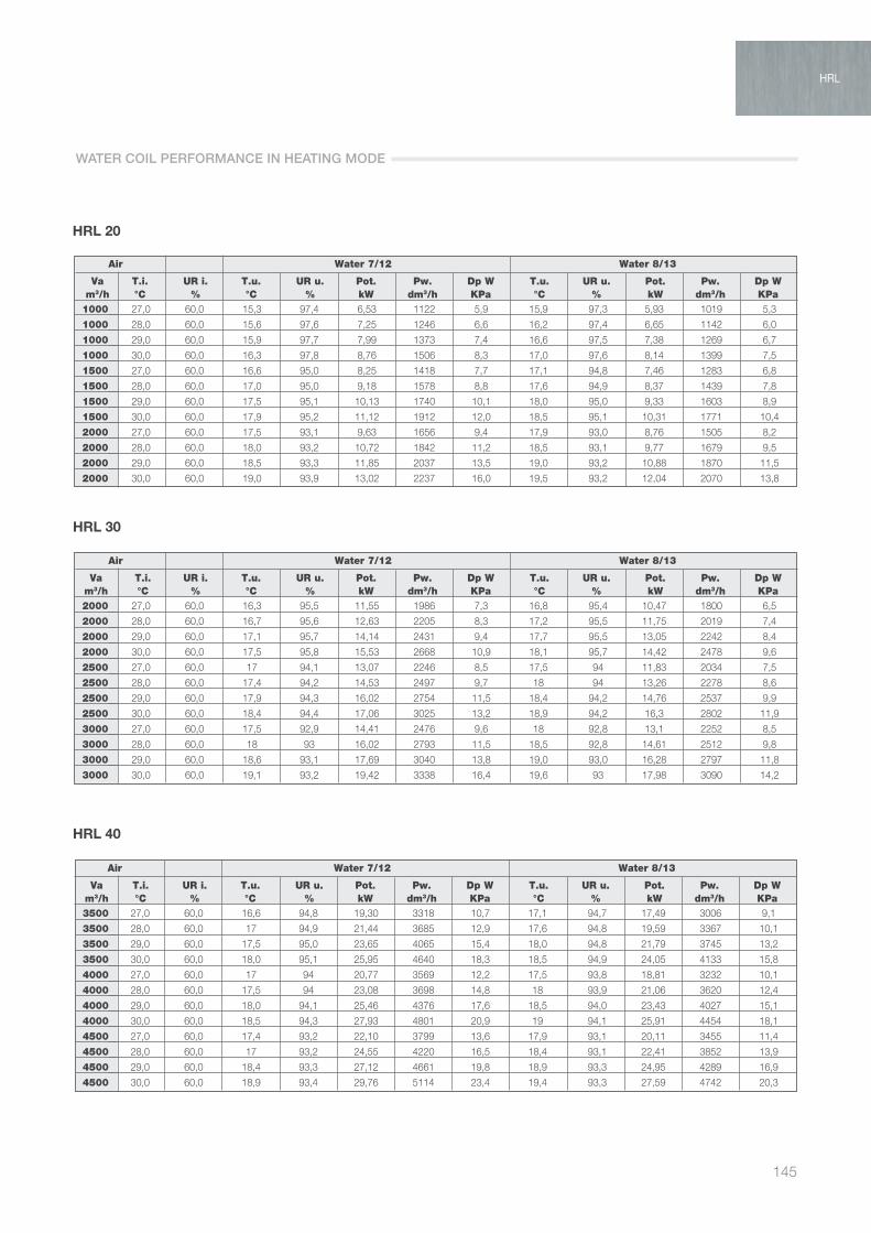
145
HRL 20
1000
1000
1000
1000
1500
1500
1500
1500
2000
2000
2000
2000
Va T.i. UR i. T.u. UR u. Pot. Pw. Dp W T.u. UR u. Pot. Pw. Dp W m3/h °C % °C % kW dm3/h KPa °C % kW dm3/h KPa
Air Water 7/12 Water 8/13
27,0 60,0 15,3 97,4 6,53 1122 5,9 15,9 97,3 5,93 1019 5,3
28,0 60,0 15,6 97,6 7,25 1246 6,6 16,2 97,4 6,65 1142 6,0
29,0 60,0 15,9 97,7 7,99 1373 7,4 16,6 97,5 7,38 1269 6,7
30,0 60,0 16,3 97,8 8,76 1506 8,3 17,0 97,6 8,14 1399 7,5
27,0 60,0 16,6 95,0 8,25 1418 7,7 17,1 94,8 7,46 1283 6,8
28,0 60,0 17,0 95,0 9,18 1578 8,8 17,6 94,9 8,37 1439 7,8
29,0 60,0 17,5 95,1 10,13 1740 10,1 18,0 95,0 9,33 1603 8,9
30,0 60,0 17,9 95,2 11,12 1912 12,0 18,5 95,1 10,31 1771 10,4
27,0 60,0 17,5 93,1 9,63 1656 9,4 17,9 93,0 8,76 1505 8,2
28,0 60,0 18,0 93,2 10,72 1842 11,2 18,5 93,1 9,77 1679 9,5
29,0 60,0 18,5 93,3 11,85 2037 13,5 19,0 93,2 10,88 1870 11,5
30,0 60,0 19,0 93,9 13,02 2237 16,0 19,5 93,2 12,04 2070 13,8
2000
2000
2000
2000
2500
2500
2500
2500
3000
3000
3000
3000
Va T.i. UR i. T.u. UR u. Pot. Pw. Dp W T.u. UR u. Pot. Pw. Dp W m3/h °C % °C % kW dm3/h KPa °C % kW dm3/h KPa
Air Water 7/12 Water 8/13
27,0 60,0 16,3 95,5 11,55 1986 7,3 16,8 95,4 10,47 1800 6,5
28,0 60,0 16,7 95,6 12,63 2205 8,3 17,2 95,5 11,75 2019 7,4
29,0 60,0 17,1 95,7 14,14 2431 9,4 17,7 95,5 13,05 2242 8,4
30,0 60,0 17,5 95,8 15,53 2668 10,9 18,1 95,7 14,42 2478 9,6
27,0 60,0 17 94,1 13,07 2246 8,5 17,5 94 11,83 2034 7,5
28,0 60,0 17,4 94,2 14,53 2497 9,7 18 94 13,26 2278 8,6
29,0 60,0 17,9 94,3 16,02 2754 11,5 18,4 94,2 14,76 2537 9,9
30,0 60,0 18,4 94,4 17,06 3025 13,2 18,9 94,2 16,3 2802 11,9
27,0 60,0 17,5 92,9 14,41 2476 9,6 18 92,8 13,1 2252 8,5
28,0 60,0 18 93 16,02 2793 11,5 18,5 92,8 14,61 2512 9,8
29,0 60,0 18,6 93,1 17,69 3040 13,8 19,0 93,0 16,28 2797 11,8
30,0 60,0 19,1 93,2 19,42 3338 16,4 19,6 93 17,98 3090 14,2
3500
3500
3500
3500
4000
4000
4000
4000
4500
4500
4500
4500
Va T.i. UR i. T.u. UR u. Pot. Pw. Dp W T.u. UR u. Pot. Pw. Dp W m3/h °C % °C % kW dm3/h KPa °C % kW dm3/h KPa
Air Water 7/12 Water 8/13
27,0 60,0 16,6 94,8 19,30 3318 10,7 17,1 94,7 17,49 3006 9,1
28,0 60,0 17 94,9 21,44 3685 12,9 17,6 94,8 19,59 3367 10,1
29,0 60,0 17,5 95,0 23,65 4065 15,4 18,0 94,8 21,79 3745 13,2
30,0 60,0 18,0 95,1 25,95 4640 18,3 18,5 94,9 24,05 4133 15,8
27,0 60,0 17 94 20,77 3569 12,2 17,5 93,8 18,81 3232 10,1
28,0 60,0 17,5 94 23,08 3698 14,8 18 93,9 21,06 3620 12,4
29,0 60,0 18,0 94,1 25,46 4376 17,6 18,5 94,0 23,43 4027 15,1
30,0 60,0 18,5 94,3 27,93 4801 20,9 19 94,1 25,91 4454 18,1
27,0 60,0 17,4 93,2 22,10 3799 13,6 17,9 93,1 20,11 3455 11,4
28,0 60,0 17 93,2 24,55 4220 16,5 18,4 93,1 22,41 3852 13,9
29,0 60,0 18,4 93,3 27,12 4661 19,8 18,9 93,3 24,95 4289 16,9
30,0 60,0 18,9 93,4 29,76 5114 23,4 19,4 93,3 27,59 4742 20,3
HRL 30
HRL 40
WATER COIL PERFORMANCE IN HEATING MODE
HRL

AIR TREATMENT
146
HRL 60
5000
5000
5000
5000
5500
5500
5500
5500
6000
6000
6000
6000
Va T.i. UR i. T.u. UR u. Pot. Pw. Dp W T.u. UR u. Pot. Pw. Dp W m3/h °C % °C % kW dm3/h KPa °C % kW dm3/h KPa
Air Water 7/12 Water 8/13
27,0 60,0 17,3 93,9 24,51 4212 6,3 17,8 93,8 22,18 3811 5,6
28,0 60,0 17,8 93,9 27,34 4698 7,1 18,3 93,9 22,86 4222 6,4
29,0 60,0 18,3 94,0 30,28 5204 8,1 18,8 93,9 27,77 4772 7,2
30,0 60,0 18,8 94,2 33,34 5730 9,1 19,3 94 30,8 5293 8,2
27,0 60,0 17,6 93,3 25,78 4431 6,6 18,1 93,2 23,39 4020 6
28,0 60,0 18,1 93,3 28,75 4942 7,5 18,6 93,3 26,15 4494 6,7
29,0 60,0 18,6 93,4 31,86 5476 8,6 19,1 93,3 29,2 5018 7,7
30,0 60,0 19,1 93,5 35,08 6030 9,8 19,6 93,4 32,4 5568 8,8
27,0 60,0 17,9 92,7 27,00 4641 7 18,3 92,7 24,54 4218 6,3
28,0 60,0 18,4 92,8 30,09 5171 8 18,8 92,7 27,4 4708 7,1
29,0 60,0 18,9 92,9 33,32 5730 9,1 19,4 92,7 30,55 5250 8,1
30,0 60,0 19,5 92,9 36,73 6312 10,6 19,9 92,9 33,89 5825 9,3
7000
7000
7000
7000
8000
8000
8000
8000
9000
9000
9000
9000
Va T.i. UR i. T.u. UR u. Pot. Pw. Dp W T.u. UR u. Pot. Pw. Dp W m3/h °C % °C % kW dm3/h KPa °C % kW dm3/h KPa
Air Water 7/12 Water 8/13
27,0 60,0 16,6 95 38,54 6624 7,7 17,1 95 34,85 5989 6,8
28,0 60,0 17 95,1 42,85 7364 8,8 17,6 95,1 39,11 6722 7,8
29,0 60,0 17,5 95,3 47,28 8127 10,1 18,0 95,2 43,55 7484 8,9
30,0 60,0 17,9 95,4 51,98 8933 12,0 18,5 95,2 48,12 8271 10,4
27,0 60,0 17 94,2 41,44 7122 8,4 17,5 94,1 37,53 6451 7,4
28,0 60,0 17,5 94,3 46,11 7924 9,7 18 94,2 42,08 7231 8,5
29,0 60,0 18,0 94,4 50,92 8753 11,6 18,5 94,3 46,84 8051 9,8
30,0 60,0 18,4 94,5 55,97 9620 13,8 18,9 94,4 51,84 8909 11,9
27,0 60,0 17,4 93,5 44,13 7585 9,1 17,8 93,3 40,06 6885 8
28,0 60,0 17,9 93,6 49,10 8439 10,8 18,4 93,5 44,75 7692 9,3
29,0 60,0 18,4 93,6 54,27 9327 13,0 18,9 93,5 49,87 8570 11,1
30,0 60,0 18,9 93,7 59,65 10252 15,5 19,4 93,6 55,19 9485 13,3
10000
10000
10000
10000
11000
11000
11000
11000
12000
12000
12000
12000
Va T.i. UR i. T.u. UR u. Pot. Pw. Dp W T.u. UR u. Pot. Pw. Dp W m3/h °C % °C % kW dm3/h KPa °C % kW dm3/h KPa
Air Water 7/12 Water 8/13
27,0 60,0 16,5 94,7 55,85 9600 15,9 17,1 94,6 50,7 87313 13,3
28,0 60,0 17 94,8 61,94 10646 19,2 17,5 94,7 56,73 3550 16,3
29,0 60,0 17,4 94,9 68,17 11717 22,9 18,0 94,7 62,9 10810 19,7
30,0 60,0 17,9 95,0 74,67 12830 27,1 18,5 94,9 69,33 11915 23,5
27,0 60,0 16,8 94,1 58,89 10122 17,5 17,4 94 56,42 9181 14,8
28,0 60,0 17,3 94,2 65,28 11221 21,2 17,8 94 59,68 10257 17,9
29,0 60,0 17,8 94,3 71,30 12355 25,3 18,3 94,1 66,28 11391 21,7
30,0 60,0 18,3 94,4 78,82 13546 29,9 18,8 94,1 73,1 12564 25,9
27,0 60,0 17,1 93,5 61,67 10600 19,1 17,6 93,5 56,04 9631 15,9
28,0 60,0 17,6 93,6 68,42 11759 23,1 18,1 93,5 62,56 10752 19,5
29,0 60,0 18,1 93,7 75,40 12959 27,6 18,6 93,5 69,45 11935 23,6
30,0 60,0 18,6 93,8 82,55 14188 32,6 19,1 93,5 76,67 13177 28,3
HRL 90
HRL 120
WATER COIL PERFORMANCE IN HEATING MODE

147
HRL
HRL 150
13000
13000
13000
13000
14000
14000
14000
14000
15000
15000
15000
15000
Va T.i. UR i. T.u. UR u. Pot. Pw. Dp W T.u. UR u. Pot. Pw. Dp W m3/h °C % °C % kW dm3/h KPa °C % kW dm3/h KPa
Air Water 7/12 Water 8/13
27,0 60,0 17,4 93 64,36 11062 20,6 17,8 92,9 58,6 10070 17,3
28,0 60,0 17,9 93,1 71,39 12259 24,9 18,4 93 65,27 11218 21,1
29,0 60,0 18,4 93,2 78,70 13526 29,8 18,9 93,0 72,5 12460 25,6
30,0 60,0 18,9 93,2 86,23 14821 35,3 19,4 93,2 80,01 13751 30,6
27,0 60,0 17,6 92,5 66,91 11499 22,2 18 92,4 61,02 10287 18,6
28,0 60,0 18,1 92,6 74,18 12790 26,8 18,6 92,5 67,87 11665 22,6
29,0 60,0 18,7 92,7 81,85 14068 32,1 19,1 92,8 75,42 12962 27,5
30,0 60,0 19,2 92,8 89,30 15416 38,0 19,7 92,7 83,17 14294 32,9
27,0 60,0 17,8 92,1 69,37 11923 23,7 18,2 92 63,37 10891 20
28,0 60,0 18,4 92,1 76,90 13217 28,6 18,8 92,1 70,4 12099 24,2
29,0 60,0 18,9 92,2 84,79 14573 34,3 19,3 92,2 78,1 13423 29,3
30,0 60,0 19,4 92,3 92,99 15983 40,6 19,9 92,2 86,18 14811 39,1
WATER COIL PERFORMANCE IN HEATING MODE
HRL

Vortice Elettrosociali S.p.AStrada Cerca, 2Frazione di Zoate20067 Tribiano (Milano)Tel. (+39) 02 906991Fax (+39) 02 [email protected]
Loranvia B. Brugnoli, 337063 Isola della ScalaVerona - ItaliaTel. (+39) 045.6631042Fax. (+39) [email protected]
Vortice LimitedBeeches House-Eastern AvenueBurton on TrentDE13 0BBTel. (+44) 1283-49.29.49Fax (+44) 1283-54.41.21United [email protected]
Vortice France72, Rue Baratte-Cholet94106 Saint MaurCedexTél. (+33) 1.55.12.50.00Fax (+33) 1.55.12.50.01Francecontact@vortice-france.comwww.vortice-france.com
Cod
e 5.
170.
084.
992