catalog pages: solahd sdn-c performance din rail …€¦ · certifications ensure that the sdn-c...
TRANSCRIPT

Power Supplies
Visit our website at www.emerson.com or contact Technical Services at (800) 377-4384 with any questions. © June 2018
124
High performance specifications and extensive international certifications ensure that the SDN-C is suitable for the most extreme environments, including hazardous locations and off-shore applications. Features like wide operating temperature range, power boost capability, and adjustable output voltage ensure reliable operation in the harshest industrial environments. Parallel operation, extensive LED diagnostics, and universal AC or DC input voltage simplify installation and maintenance. For added reliability, the SDN-C power supplies can be used with the SolaHD Redundancy modules to provide redundant power supply operation.
Applications
• Industrial Automation
• Process Control
• Material Handling and Conveyors
• Hazardous Locations
• Marine Applications
Features
• Extensive international hazardous location certifications, including Class 1 Zone 2, ATEX, IECEx, ExEAC. Haz-ardous location temperature code (T-Code) rating of T4.
• International off-shore certifications, including ABS and DNV-GL
• PowerBoostTM enables short duration overload capabil-ity, to start loads with high inrush current
• Three LEDs provide extensive diagnostics• Dual output terminals for convenience in wiring• DC OK relay to provide diagnostic information to a PLC,
controller, or monitoring system • Universal AC and DC input voltages to accommodate
global requirements• Wide operating temperature range accommodates both
extreme hot and extreme cold environments• Active Power Factor Correction on most models• Parallel operation capability standard• Supports redundant power supply operation using op-
tional SDN Redundancy modules• 5-year limited warranty
Certifications and Compliances *
All Models
• UL 508 Listed
IND. CONT. EQ.E61379
Listed, Ind. Control Equipment, E61379
- UL 508, CSA C22.2 No. 107.1
• UL 60950 E137632
CUL/CSA-C22.2No. 234-M90
UL Recognized Component, ITE, E137632
- UL 60950-1/CSA C22.2 No. 60950-1, 2nd Edition
• EMC andLow Volt. Directive
- Low Voltage Directive
- IEC/EN60950-1, 2nd Edition
• RoHS Compliant
Models SDN 5-24-100C, SDN 10-24-100C, SDN 16-12-100C, SDN 20-24-100C, SDN 40-24-100C, SDN 5-24-480C, SDN 10-24-480C, SDN 20-24-480CD
• UL 60950 E137632
CUL/CSA-C22.2No. 234-M90
UL Recognized Component, Haz. Loc., E234790
- UL60079-0/CSA E60079-0, UL 60079-15, CSA E60079-15
- Class I, Zone 2, AEx nA nC IIC, Ex nA nC IIC
• ATEX Directive
- EN60079-0, EN60079-7, EN60079-15
- II 3 G, Ex ec nC IIC Gc
• IECEx Certified
- IEC 60079-0, IEC 60079-7, IEC 60079-15
- Ex ec nC IIC Gc
Models SDN 5-24-100C, SDN 10-24-100C, SDN 16-12-100C, SDN 20-24-100C, SDN 40-24-100C, SDN 5-24-480C, SDN 10-24-480C
• TR CU 012/2011 Safety of Equipment intended for Explosive Atmospheres
• Type Approval
Models SDN 5-24-100C, SDN 10-24-100C, SDN 16-12-100C, SDN 20-24-100C, SDN 40-24-100C
• Type Approved
Models SDN 5-24-100C, SDN 10-24-100C, SDN 20-24-100C, SDN 40-24-100C
• Certified
SDN-C Performance DIN Rail Series
* Refer to user manual for installation requirements when used in hazardous locations.
UL 508 ListedIND. CONT. EQ.
E61379
E61379 UL 60950 E137632
CUL/CSA-C22.2No. 234-M90
E137632E234790
EMC andLow Volt. DirectiveIECEx

Power Supplies
Visit our website at www.emerson.com or contact Technical Services at (800) 377-4384 with any questions. © June 2018
125
The SolaHD Difference
Rugged metal housingMultiple output connections for ease of wiring multiple devices
Single or parallel use selectable by user
Clearly labeled front panel
Multiple certifications for versatility in applications
Automatically adjusts for global Input voltages
Narrow width saves panel space
No internal fan, no extra cooling required in any power level
Adjustable output voltage
DC OK Relay Terminals provide diagnostic information to a PLC or controller
Visual LED diagnostics show input and output status (see table below)
LED Light Status Conditions
Normal AC Power Loss AC Input Low No DC High Load Overload Hot Too Hot
Input Green - Amber Green Green Green Green Green
Output Green - Green - Amber Amber Green -
Alarm - - - Red Amber Red Amber Amber
Related Products
• SDN-C Redundancy Modules
• IP67 SCP-X Extreme Environment Series
• SDU UPS
Accessories
• Chassis Mount Brackets
Power Supplies
Visit our website at www.emerson.com or contact Technical Services at (800) 377-4384 with any questions. © June 2018
126
DescriptionCatalog Number
SDN 16-12-100C SDN 5-24-100C SDN 10-24-100C SDN 20-24-100C SDN 40-24-100C
Input
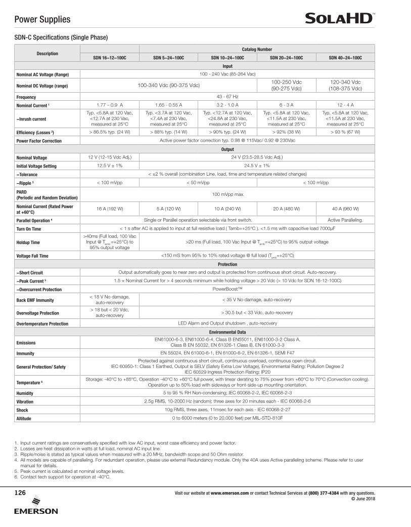
Nominal AC Voltage (Range) 100 - 240 Vac (85-264 Vac)
Nominal DC Voltage (range) 100-340 Vdc (90-375 Vdc)100-250 Vdc (90-275 Vdc)
120-340 Vdc (108-375 Vdc)
Frequency 43 - 67 Hz
Nominal Current 1 1.77 – 0.9 A 1.65 - 0.55 A 3.2 - 1.0 A 6 - 3 A 12 - 4 A
-Inrush currentTyp. <5.8A at 120 Vac,
<12.7A at 230 Vac, measured at 25°C
Typ. <3.7A at 120 Vac, <7.4A at 230 Vac, measured at 25°C
Typ. <12.7A at 120 Vac, <24.8A at 230 Vac, measured at 25°C
Typ. <5.8A at 120 Vac, <11.5A at 230 Vac, measured at 25°C
Typ. <5.8A at 120 Vac, <11.5A at 230 Vac, measured at 25°C
Efficiency (Losses 2) > 86.5% typ. (24 W) > 88% typ. (14 W) > 90% typ. (24 W) > 92% (38 W) > 93 % (67 W)
Power Factor Correction Active power factor correction typ. 0.98 @ 115Vac/ 0.92 @ 230Vac
Output
Nominal Voltage 12 V (12-15 Vdc Adj.) 24 V (23.5-28.5 Vdc Adj.)
Initial Voltage Setting 12.5 V ± 1% 24.5 V ± 1%
-Tolerance < ±2 % overall (combination Line, load, time and temperature related changes)
-Ripple 3 < 100 mVpp < 50 mVpp < 100 mVpp
PARD (Periodic and Random Deviation)
100 mVpp max
Nominal Current (Rated Power at +60°C)
16 A (192 W) 5 A (120 W) 10 A (240 W) 20 A (480 W) 40 A (960 W)
Parallel Operation 4 Single or Parallel operation selectable via front switch. Active Paralleling.
Turn On Time < 1 s after AC is applied to input at full resistive load ( Tamb=+25°C ). <1.5 ms with capacitive load 7000μF
Holdup Time>40ms (Full load, 100 Vac
Input @ Tamb =+25°C) to 95% output voltage
>20 ms (Full load, 100 Vac Input @ Tamb=+25°C) to 95% output voltage
Voltage Fall Time <150 mS from 95% to 10% rated voltage @ full load (Tamb=+25°C)
Protection
-Short Circuit Output automatically goes to near zero and output is protected from continuous short circuit. Auto-recovery.
-Peak Current 5 1.5 × Nominal Current for > 4 seconds minimum while holding voltage > 20 Vdc (> 10 Vdc for SDN 16-12-100C)
-Overcurrent Protection PowerBoost™
Back EMF Immunity< 18 V No damage,
auto-recovery< 35 V No damage, auto-recovery
Overvoltage Protection> 18 but < 20 Vdc,
auto-recovery> 30.5 but < 33 Vdc, auto-recovery
Overtemperature Protection LED Alarm and Output shutdown , auto-recovery
Environmental Data
EmissionsEN61000-6-3, EN61000-6-4, Class B EN55011, EN61000-3-2 Class A,
Class B EN 55032, EN 61326-1 Class B, EN 61000-3-3
Immunity EN 55024, EN 61000-6-1, EN 61000-6-2, EN 61326-1, SEMI F47
General Protection/ SafetyProtected against continuous short circuit, continuous overload, continuous open circuit.
IEC 60950-1: Class 1 Earthed, Output is SELV (Safety Extra Low Voltage), Environmental Rating: Pollution Degree 2 IEC 60529 Ingress Protection Rating: IP20
Temperature 6Storage: -40°C to +85°C, Operation -40°C to +60°C full power, with linear derating to 75% power from +60°C to 70°C (Convection cooling).
Operation up to 50% load with sideways or front-side-up mounting orientation.
Humidity 5 to 95 % RH Non-condensing; IEC 60068-2-2, IEC 60068-2-3
Vibration 2.5g RMS, 10-2000 Hz (random); three axes for 20 minutes each - IEC 60068-2-6
Shock 10g RMS, three axes, 11msec for each axis - IEC 60068-2-27
Altitude 0 to 6000 meters (0 to 20,000 feet) per MIL-STD-810F
SDN-C Specifications (Single Phase)
1. Input current ratings are conservatively specified with low AC input, worst case efficiency and power factor. 2. Losses are heat dissipation in watts at full load, nominal AC input line.3. Ripple/noise is stated as typical values when measured with a 20 MHz, bandwidth scope and 50 Ohm resistor.4. All models are capable of paralleling. For redundant operation, please use external Redundancy module. Only the 40A uses Active paralleling scheme. Please refer to user
manual for details. 5. Peak current is calculated at nominal voltage levels.6. Contact tech support for operation at -40°C.
Power Supplies
Visit our website at www.emerson.com or contact Technical Services at (800) 377-4384 with any questions. © June 2018
127
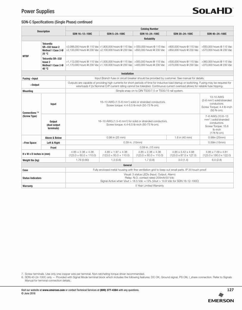
SDN-C Specifications (Single Phase) continued
DescriptionCatalog Number
SDN 16-12-100C SDN 5-24-100C SDN 10-24-100C SDN 20-24-100C SDN 40-24-100C
Reliability
MTBF
Telcordia SR-332 Issue 2Method 1 Case 3 @ 25 °C
>2,088,000 hours @ 115 Vac>2,133,000 hours @ 230 Vac
>1,800,000 hours @ 115 Vac>2,100,000 hours @ 230 Vac
> 550,000 hours @ 115 Vac>650,000 hours @ 230 Vac
>800,000 hours @ 115 Vac>850,000 hours @ 230 Vac
>550,000 hours @ 115 Vac>570,000 hours @ 230 Vac
Telcordia SR-332 Issue 2Method 1 Case 3 @ 40 °C
>1,112,000 hours @ 115 Vac>1,170,000 hours @ 230 Vac
>1,000,000 hours @ 115 Vac>1,100,000 hours @ 230 Vac
>300,000 hours @ 115 Vac>400,000 hours @ 230 Vac
>500,000 hours @ 115 Vac>570,000 hours @ 230 Vac
>360,000 hours @ 115 Vac>370,000 hours @ 230 Vac
Installation
Fusing -Input Input Branch fuse or circuit breaker should be provided by customer. See manual for details.
-OutputOutputs are capable of providing high currents for short periods of time for inductive load startup or switching. Fusing may be required for
wire/loads if 2x Nominal O/P current rating cannot be tolerated. Continuous current overload allows for reliable fuse tripping.
Mounting Simple snap-on to DIN TS35/7.5 or TS35/15 rail system.
Connections 7,8
(Screw Type)
Input16–10 AWG (1.5–6 mm2) solid or stranded conductors.
Screw torque: 4.4-6.5 lb-inch (50-73 N-cm).
13-10 AWG(3-6 mm2) solid/stranded
conductors. Screw Torque: 4.4 lb-inch
(50 N-cm).
Output(dual output terminals)
16–10 AWG (1.5–6 mm2) for solid or stranded conductors. Screw torque: 4.4-6.5 lb-inch (50-73 N-cm).
7–6 AWG (10.6–13 mm2 ) solid/stranded
conductors. Screw Torque: 15.6
lb-inch (176 N-cm)
-Free Space
Above & Below 0.98 in (25 mm) 1.6 in (40 mm) 0.98in (25mm)
Left & Right 0.39 in. (10mm) 0.59in (15mm)
Front 0.59 in. (15 mm)
H x W x D inches in (mm)4.85 × 2.36 × 4.36
(123.0 × 60.0 × 110.0)4.85 × 1.97 × 4.36
(123.0 × 50.0 × 110.0)4.85 × 2.36 × 4.36
(123.0 × 60.0 × 110.0)4.85 x 3.42 x 4.98
(123.0 x 87.0 x 127.0)4.85 x 7.09 x 4.81
(123.0 x 180.0 x 122.0)
Weight lbs (kg) 1.76 (0.80) 1.3 (0.6) 1.7 (0.8) 3.0 (1.4) 6.0 (2.8)
General
Case Fully enclosed metal housing with fine ventilation grid to keep out small parts. IP 20 touch proof
Status IndicatorsVisual: 3 status LEDs (Input, Output, Alarm)Relay: N.O. contact rated 200mA/50 Vdc
Signal Active when Vout > 18.5 Vdc +/-5% (Vout > 10.8 Vdc for SDN 16-12-100C)
Warranty 5 Year Limited Warranty
7. Screw terminals. Use only one copper wire per terminal. Non-ratcheting torque driver recommended.8. SDN 40-24-100C only — Provided with Signal Mode terminal block which includes the following features: DC OK, Ground signal, PS ON, I_share connection. Refer to Signals
Manual for terminal connection details..

Power Supplies
Visit our website at www.emerson.com or contact Technical Services at (800) 377-4384 with any questions. © June 2018
128
SDN-C Specifications (Three Phase)
1. In the event of a phase loss, the power supply will continue to operate normally. However, the resulting lower rectified RMS voltage can cause excessive heat build up, which may eventually cause the unit to shut down if maximum operating temperature is exceeded.
2. Input current ratings are specified with low AC 3-phase input, line conditions, worst case efficiency values and power factor spikes. Input current at nominal AC 3-phase input will typically be half these values.
3. Losses are heat dissipation in watts at full load, nominal line.4. 24-28 Vdc adjustable guaranteed at full load.5. Ripple/noise is stated as typical values when measured with a 20 MHZ, bandwidth scope and 50 Ohm resistor6. All models are capable of paralleling. For redundant operation, please use external Redundancy module. Only the 40A uses active paralleling scheme. Please refer to user manual for details.7. SDN 20 and SDN 40 are capable of delivering 150% load for approximately 4s before the unit will go to HICCUP mode. SDN 5 and 10 will maintain minimum 4s to deliver 150% load then drops to almost
zero Vout. The output voltage will immediately drop to almost zero when load rises above 150%.8. Contact Tech Support for operation -40°C.
DescriptionCatalog Number
SDN 5-24-480C SDN 10-24-480C SDN 20-24-480CD SDN 40-24-480C
Input
Nominal AC Voltage (Range) 380 - 480 Vac (320 - 540 Vac), 3-phase
Two-phase input 1 Yes
Nominal DC Voltage (Range) 600 Vdc (+/- 50Vdc)
Frequency 50/60 Hz
Nominal Current 2 3 x 0.5A 3 x 0.8A 3 x 0.9A 3 x 1.6A
-Inrush current max. Typ. < 25 A Negligible
Efficiency (Losses 3) > 85% (18 W) 91% (24W) 93% (42 W) 94% (78 W)
Power Factor Correction Meets EN61000-3-2 Class A Active Power Factor Correction > 0.92
Output
Nominal Voltage 4 24 V (23.5 – 28.5 Vdc Adj.)
Initial Voltage Setting 24.5 V ± 1%
-Tolerance < ±2 % overall (combination Line, load, time and temperature related changes)
-Ripple 5 < 50 mVpp < 100 mVpp
PARD (Periodic and Random Deviation)
100 mVpp max 200 mVpp max
Nominal Current (Rated Power) 5 A (120 W) 10 A (240 W) 20 A (480 W) 40 A (960 W)
Parallel Operation 6 Single or Parallel operation selectable via front switch. Active Paralleling.
Turn On Time < 1 s after AC is applied to input at full resistive load ( Tamb=+25°C ). <1.5 s With capacitive load 7000μF
Holdup Time (Full load, 100 Vac Input @ T = +25°C)
20 ms 15 ms
Voltage Fall Time <150 mS from 95% to 10% rated voltage @ full load (T =+25°C)
Protection
-Short Circuit Current Voltage output automatically goes to near zero and output is protected from continuous short circuit. Auto-recovery.
-Peak Current 7 1.5 × Nominal Current for > 4 seconds minimum while holding voltage > 20 Vdc
-Current Limit PowerBoost™
Back EMF Immunity < 35 V No damage, auto-recovery
Overvoltage Protection > 30.5 but < 33 Vdc, auto-recovery
Over Temperature Protection LED Alarm and Output shutdown , auto-recovery
Environmental Data
EmissionsEN 61000-6-3, EN 55011 Class B, EN 55022 Class B, EN 61326-1,
EN 61000-3-2, EN 61000-3-3
EN 61000-6-3, EN 55011 Class B, EN 55032 Class B, EN 61326-1, EN 61000-3-2, EN 61000-3-3
EN 55011 Class B, EN 55022 Class B, EN 61000-3-2,
EN 61000-3-3
Immunity EN 55024, EN 61326-1, EN 61000-6-1, EN 61000-6-2, SEMI F47EN 55024, EN 61326-1, EN
61000-6-1, EN 61000-6-2, SEMI F47
EN 61000-4-2, EN 61000-4-4, EN 61000-4-5, SEMI F47
General Protection/ SafetyProtected against continuous short circuit, continuous overload, continuous open circuit.
IEC 60950-1: Class 1 Earthed, Output is SELV (Safety Extra Low Voltage), Environmental Rating: Pollution Degree 2 IEC 60529 Ingress Protection Rating: IP20
Temperature 8Storage: -40°C to + 85°C, Operation -40°C to +60°C full power, with linear derating to 75% power from 60 to 70°C (Convection cooling, no
forced air required). Operation up to 50% load permissible with sideways or front-side-up mounting orientation.
Humidity 5 to 95 % RH Non-condensing, IEC 60068-2-2, IEC 60068-2-3
Vibration 2.5g RMS, 10-2000 Hz (random); three axes for 20 minutes each - IEC 60068-2-6
Shock 10g RMS, three axes, 11mseconds for each axis - IEC 60068-2-27
Altitude 0 to 3000 meters (0 to 10,000 feet)
Power Supplies
Visit our website at www.emerson.com or contact Technical Services at (800) 377-4384 with any questions. © June 2018
129
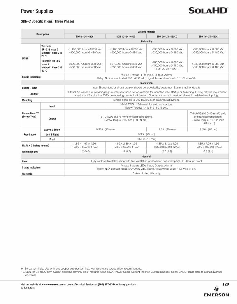
SDN-C Specifications (Three Phase)
DescriptionCatalog Number
SDN 5-24-480C SDN 10-24-480C SDN 20-24-480CD SDN 40-24-480C
Reliability
MTBF
Telcordia SR-332 Issue 2Method 1 Case 3 @ 25 °C
>1,100,000 hours @ 380 Vac>900,000 hours @ 480 Vac
>1,400,000 hours @ 380 Vac>900,000 hours @ 480 Vac
>630,000 hours @ 380 Vac>630,000 hours @ 480 Vac
>600,000 hours @ 380 Vac>550,000 hours @ 480 Vac
Telcordia SR-332 Issue 2Method 1 Case 3 @ 40 °C
>600,000 hours @ 380 Vac>500,000 hours @ 480 Vac
>910,000 hours @ 380 Vac>600,000 hours @ 480 Vac
>460,000 hours @ 380 Vac>450,000 hours @ 480 Vac
SDN 20-24-480CR
>380,000 hours @ 380 Vac>360,000 hours @ 480 Vac
Status IndicatorsVisual: 3 status LEDs (Input, Output, Alarm)
Relay: N.O. contact rated 200mA/50 Vdc, Signal Active when Vout> 18.5 Vdc +/-5%
Installation
Fusing -Input Input Branch fuse or circuit breaker should be provided by customer. See manual for details.
-OutputOutputs are capable of providing high currents for short periods of time for inductive load startup or switching. Fusing may be required for
wire/loads if 2x Nominal O/P current rating cannot be tolerated. Continuous current overload allows for reliable fuse tripping.
Mounting Simple snap-on to DIN TS35/7.5 or TS35/15 rail system.
Connections 9,10
(Screw Type)
Input16-10 AWG (1.5-6 mm2) for solid conductors.
Screw Torque: 4.4 lb-in (~ 50 N-cm).
Output16-10 AWG (1.5-6 mm2) for solid conductors.
Screw Torque: 7 lb-inch (~ 80 N-cm)
7–6 AWG (10.6–13 mm2 ) solid or stranded conductors.
Screw Torque: 15.6 lb-inch (176 N-cm)
-Free Space
Above & Below 0.98 in (25 mm) 1.6 in (40 mm) 2.80 in (70mm)
Left & Right 0.98in (25mm)
Front 0.59 in. (15 mm)
H x W x D inches in (mm)4.85 × 1.97 × 4.36
(123.0 × 50.0 × 110.0)4.85 × 2.36 × 4.36
(123.0 × 60.0 × 110.0)4.85 x 3.42 x 4.98
(123.0 x 87.0 x 127.0)4.85 x 7.09 x 4.66
(123.0 x 180.0 x 119.0)
Weight lbs (kg) 1.2 (0.5) 1.5 (0.7) 2.7 (1.2) 5.3 (2.4)
General
Case Fully enclosed metal housing with fine ventilation grid to keep out small parts. IP 20 touch proof
Status IndicatorsVisual: 3 status LEDs (Input, Output, Alarm)
Relay: N.O. contact rated 200mA/50 Vdc, Signal Active when Vout> 18.5 Vdc +/-5%
Warranty 5 Year Limited Warranty
9. Screw terminals. Use only one copper wire per terminal. Non-ratcheting torque driver recommended.10. SDN 40-24-480C only: Output signaling terminal block features (Shut down, Power Good, Current Monitor, Current Balance, signal GND). Please refer to Signals Manual
for details.

Power Supplies
Visit our website at www.emerson.com or contact Technical Services at (800) 377-4384 with any questions. © June 2018
130
SDN-C Series Dimensions
SDN 40-24-480C Dimensions
Catalog Number
Dimensions - inches (mm)
H W D
SDN 5-24-100C 4.85 (123.0) 1.97 (50.0) 4.36 (111.0)
SDN 10-24-100C 4.85 (123.0) 2.36 (60.0) 4.36 (111.0)
SDN 16-12-100C 4.85 (123.0) 2.36 (60.0) 4.36 (111.0)
SDN 20-24-100C 4.85 (123.0) 3.42 (87.0) 4.98 (127.0)
SDN 5-24-480C 4.85 (123.0) 1.97 (50.0) 4.36 (111.0)
SDN 10-24-480C 4.85 (123.0) 2.36 (60.0) 4.36 (111.0)
SDN 20-24-480CD 4.85 (123.0) 3.42 (87.0) 4.98 (127.0)
Catalog Number
Dimensions - inches (mm)
H W D
SDN 40-24-100C 4.85 (123.0) 7.09 (180.0) 4.81 (122.0)
SDN 40-24-480C 4.85 (123.0) 7.09 (180.0) 4.66 (119.0)
SDN 40-24-100C and SDN 40-24-480C output signaling terminal block features: Shut Down, Power Good, Current Monitor, Current Balance, GND, and active current sharing through I_SHARE connectors (See Signals Manual for connection information).
Power Supply
4.85
in. [
123.
3 m
m]
1.97 in.[50.0 mm] 4.36 in. [110.8 mm]
5.51
in. [
140.
0 m
m]
4.68 in. [118.8 mm]
4.78 in. [121.6 mm]
H
WD
SDN5-24-100C
Voltage adjustment potentiometer located on top of power supply
Power Supply
7.09 in. [180.0 mm] 4.81 in. [122.2 mm]
5.35 in. [136.0 mm]
4.85
in. [
123.
3 m
m]
S O L A
H
D + 0.54 in (13.80 mm)
SDN 40-24-100C Dimensions
Power Supply
5.51
in. (
139.
96 m
m)
W W D D
D + 0.54 in (13.80 mm)Signal Connector
Power Supply
H
Power Supplies
Visit our website at www.emerson.com or contact Technical Services at (800) 377-4384 with any questions. © June 2018
131
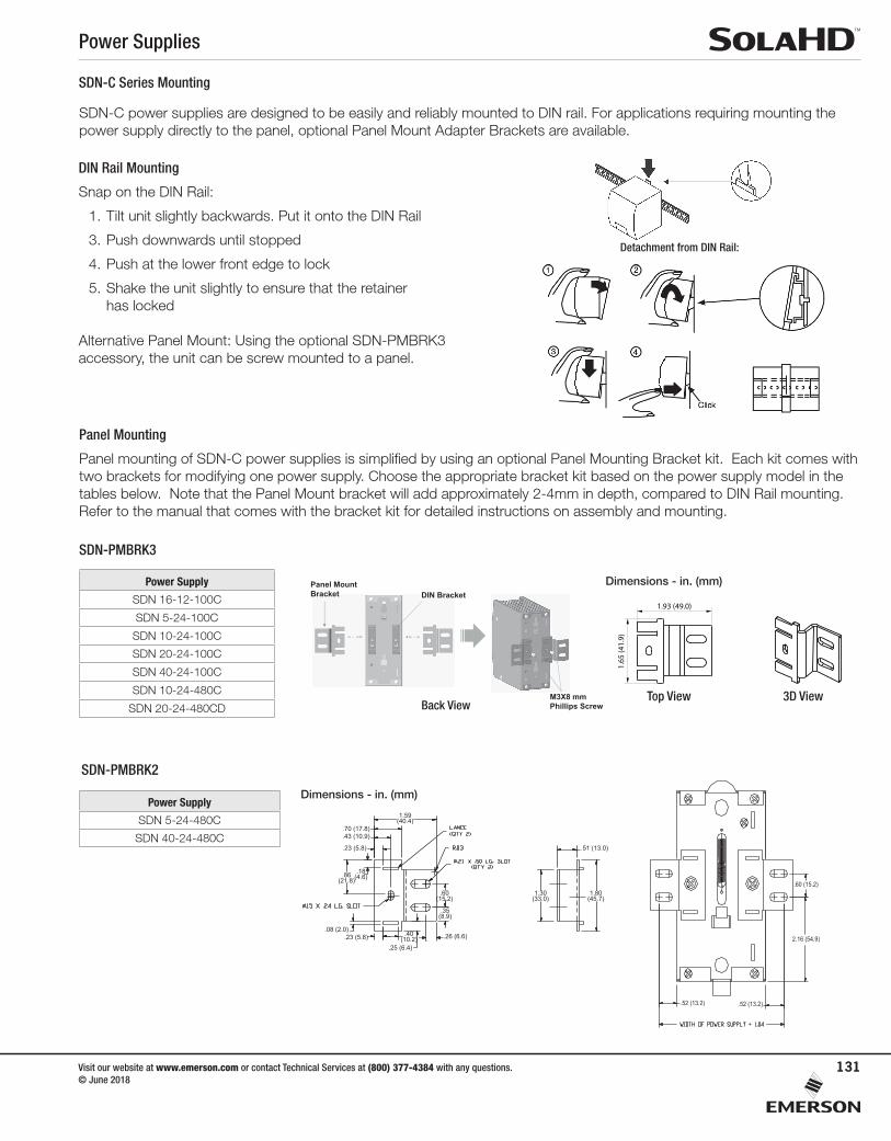
SDN-PMBRK3
SDN-C power supplies are designed to be easily and reliably mounted to DIN rail. For applications requiring mounting the power supply directly to the panel, optional Panel Mount Adapter Brackets are available.
SDN-PMBRK2
SDN-C Series Mounting
DIN Rail Mounting
Snap on the DIN Rail:
1. Tilt unit slightly backwards. Put it onto the DIN Rail
3. Push downwards until stopped
4. Push at the lower front edge to lock
5. Shake the unit slightly to ensure that the retainer has locked
Alternative Panel Mount: Using the optional SDN-PMBRK3 accessory, the unit can be screw mounted to a panel.
Panel Mounting
Panel mounting of SDN-C power supplies is simplified by using an optional Panel Mounting Bracket kit. Each kit comes with two brackets for modifying one power supply. Choose the appropriate bracket kit based on the power supply model in the tables below. Note that the Panel Mount bracket will add approximately 2-4mm in depth, compared to DIN Rail mounting. Refer to the manual that comes with the bracket kit for detailed instructions on assembly and mounting.
Detachment from DIN Rail:
Power Supply Accessories
SDN-PMBRK3Panel Mount Brackets Installation Manual
P/N: A272-289 REV. 1 (07/16)©2016 Appleton Grp LLC d/b/a Appleton GroupAll rights reserved. Specificationssubject to change without notice.
Dimensions in Inches (Millimeters)
1. Remove the M3X6 mm Phillips Screws, shoulder screw, plastic slide, spring and C-Insert from the DIN Brackets.
This set consists of two panel mount brackets, which replace the existing two DIN mounting brackets at the back of the unit.
FOR USE WITH:
CHASSIS MOUNTING
SDN 5-24-100CSDN 10-24-100CSDN 40-24-100CSDN 10-24-480CSDN 2X20RED
DIN Bracket
2. Retain and slide back the two DIN brackets to use as a guide for the installation of the panel mount brackets.
3. Push and slide the panel mount brackets on the top of DIN bracket and secure with M3X8 mm Phillips Screw and lock washer (use 7kgf torque).
Two M3x8 mm phillips screwsTwo bracketsTwo lock washers
Four 8-32 x 1/2” screws for mounting unit to panelFour 8-32 flat washers
INCLUDED:
NOT INCLUDED:
C-InsertSpring
Plastic slide
Shoulder screw
M3X6 mmPhillips Screw
DIN Bracket
Panel Mount Brackets Installation
7 983472 00651
Top View 3D View
CAUTION:Risk of Electric Shock and Personal Injury
Ensure unit is disconnected from all power sources prior to replacing brackets.
Panel Mount Bracket DIN Bracket
M3X8 mmPhillips Screw 1.
65 (4
1.9)
0.87 (22.1)
0.60
(15.
2)
1.47 (37.3)
Back View
Power Supply Accessories
SDN-PMBRK3Panel Mount Brackets Installation Manual
P/N: A272-289 REV. 1 (07/16)©2016 Appleton Grp LLC d/b/a Appleton GroupAll rights reserved. Specificationssubject to change without notice.
Dimensions in Inches (Millimeters)
1. Remove the M3X6 mm Phillips Screws and C-Insert from the DIN Brackets.
This set consists of two panel mount brackets, which replace the existing two DIN mounting brackets at the back of the unit.
FOR USE WITH:
CHASSIS MOUNTING
SDN 5-24-100CSDN 10-24-100CSDN 40-24-100CSDN 10-24-480CSDN 2X20RED
DIN Bracket
2. Retain and slide back the two DIN brackets to use as a guide for the installation of the panel mount brackets.
3. Push and slide the panel mount brackets on the top of DIN bracket and secure with M3X10 mm Phillips Screw and lock washer (use 7kgf torque).
Two M3x10 mm phillips screwsTwo bracketsTwo M3 lock washers
Four 8-32 x 1/2” screws for mounting unit to panelFour 8-32 flat washers
INCLUDED:
NOT INCLUDED:
C-Insert
M3X6 mmPhillips Screw
DIN Bracket
Panel Mount Brackets Installation
7 983472 00651
1.93 (49.0)
Top View 3D View
1.65
(41.
9)
CAUTION:Risk of Electric Shock and Personal Injury
Ensure unit is disconnected from all power sources prior to replacing brackets.
Panel Mount Bracket DIN Bracket
Lock washers
M3X10 mmPhillips Screw
Top View 3D View
Power Supply
SDN 16-12-100C
SDN 5-24-100C
SDN 10-24-100C
SDN 20-24-100C
SDN 40-24-100C
SDN 10-24-480C
SDN 20-24-480CD
Power Supply
SDN 5-24-480C
SDN 40-24-480C
1.59(40.4)
.18(4.6).86
(21.8)
.40(10.2)
.60(15.2)
1.30(33.0)
1.80(45.7)
.35(8.9)
.70 (17.8)
.51 (13.0)
.43 (10.9)
.23 (5.8)
.08 (2.0).23 (5.8)
.25 (6.4)
.26 (6.6)
.52 (13.2) .52 (13.2)
2.16 (54.9)
.60 (15.2)
Dimensions - in. (mm)
Dimensions - in. (mm)