catalog pmax low-voltage compact bus duct system without magnetic aluminum, ... impedance and...
TRANSCRIPT

— C ATALOG
Pmax low-voltage compact bus duct system

2 S YS TE M I NTRO D U C TI O N PM A X B US D U C T S Y S TEM
PM A X B US D U C T S Y S TEM 3
06 System overview
07 Product features
09 Technical parameter
11 Functional unit
17 Installation introduction
19 Numbering guideline
—Pmax low-voltage compact bus duct systemContents

4 S YS TE M I NTRO D U C TI O N PM A X B US D U C T S Y S TEM
Manufacturing floor
PM A X B US D U C T S Y S TEM 5
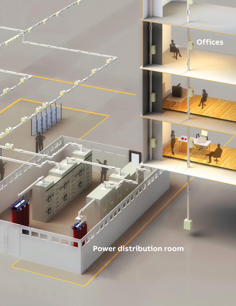
Offices
Power distribution room

6 S YS TE M I NTRO D U C TI O N PM A X B US D U C T S Y S TEM
—System overview
—The Pmax series compact bus duct system is a safe, reliable, compact, efficient and customized low-voltage energy transmission solution that can fully replace traditional cable, saving time, space and energy consumption. Its sandwich structure and closely arranged conductors facilitate overall heat dissipation, and the compactness of its structure reduces loss and voltage drop. The plug-in unit can be installed on the load output side and arranged as needed, offering flexibility, high efficiency and economy of space.
Pmax series bus duct is ideal for use in airports, rail transit projects, data centers, large shopping malls, hospitals, industrial plants and other projects as an effective high-current power distribution system.
The Pmax system is applicable to power supply and distribution systems including three-phase three-wire, three-phase four-wire and three-phase five-wire (using enclosure as PE or using separate PE), with a frequency of 50 –60 Hz, rated operating voltage up to 1,000 V, rated insulation voltage up to 1,000 V and rated operating current of 250–6,300 A.
The protection rating is up to IP66 for Pmax-C/A and up to IP68 for the anti-corrosive and explosion-proof bus bar Pmax-R series. Fire-resistant bus bar Pmax-F series has passed strict fire resistance testing of bus duct (tested in accordance with the GA/T 537-2005 standard of Ministry of Public Security) and been awarded CCC certification.
The Pmax series compact bus duct system complies with IEC61439-1, IEC61439-6, GB7251.1 and GB7251.6 standards. In addition to CCC certification, it has KEMA-KEUR and ASTA certifications, which are some of the most stringent in the industry.
The Pmax system incorporates the latest technology in materials and transcends former limitations in the bus duct design and manufacturing industry. For example, the Pmax system makes use of a new type of super-high-conductivity conductor material, developed by the ABB Material Research Institute, which challenges the traditional industry practice requiring only copper and silver conductors.
The Pmax system enclosure is made from a special material without magnetic aluminum, magnesium or silicon. This not only reduces the dead weight of the bus duct itself, but also largely decreases the effects of these materials on the bus duct system, including high eddy current and magnetic hysteresis loss.
Compared to traditional four-piece structures, the two-piece structure design of the Pmax system reduces the temperature rise of the enclosure and provides greater dynamic thermal stability.
For applications requiring increased insulation, powdered vulcanized insulation is available as an option, offering improved performance over the the insulation film used with traditional bus duct.
Optional conductor coatings include tin and silver to provide customers with transparent, efficient, stable and reliable project customization schemes.
As a bus duct manufacturer with its own conductor processing plant, ABB implements its strict quality control standards for Pmax series bus duct starting from raw material stage and continuing through product design, measurement, production, transportation, installation, maintenance and all other phases of the industrial chain.
PM A X B US D U C T S Y S TEM 7
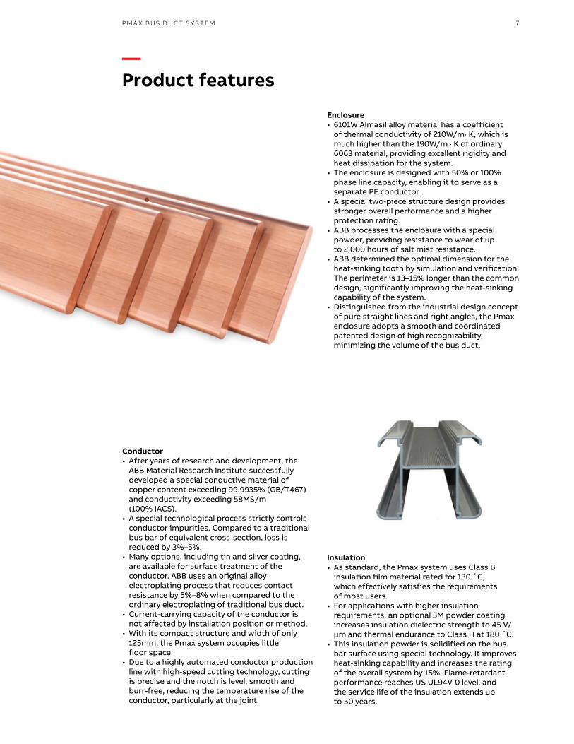
Conductor • After years of research and development, the
ABB Material Research Institute successfully developed a special conductive material of copper content exceeding 99.9935% (GB/T467) and conductivity exceeding 58MS/m (100% IACS).
• A special technological process strictly controls conductor impurities. Compared to a traditional bus bar of equivalent cross-section, loss is reduced by 3%–5%.
• Many options, including tin and silver coating, are available for surface treatment of the conductor. ABB uses an original alloy electroplating process that reduces contact resistance by 5%–8% when compared to the ordinary electroplating of traditional bus duct.
• Current-carrying capacity of the conductor is not affected by installation position or method.
• With its compact structure and width of only 125mm, the Pmax system occupies little floor space.
• Due to a highly automated conductor production line with high-speed cutting technology, cutting is precise and the notch is level, smooth and burr-free, reducing the temperature rise of the conductor, particularly at the joint.
Enclosure • 6101W Almasil alloy material has a coefficient
of thermal conductivity of 210W/m· K, which is much higher than the 190W/m · K of ordinary 6063 material, providing excellent rigidity and heat dissipation for the system.
• The enclosure is designed with 50% or 100% phase line capacity, enabling it to serve as a separate PE conductor.
• A special two-piece structure design provides stronger overall performance and a higher protection rating.
• ABB processes the enclosure with a special powder, providing resistance to wear of up to 2,000 hours of salt mist resistance.
• ABB determined the optimal dimension for the heat-sinking tooth by simulation and verification. The perimeter is 13–15% longer than the common design, significantly improving the heat-sinking capability of the system.
• Distinguished from the industrial design concept of pure straight lines and right angles, the Pmax enclosure adopts a smooth and coordinated patented design of high recognizability, minimizing the volume of the bus duct.
Insulation• As standard, the Pmax system uses Class B
insulation film material rated for 130 ˚C, which effectively satisfies the requirements of most users.
• For applications with higher insulation requirements, an optional 3M powder coating increases insulation dielectric strength to 45 V/μm and thermal endurance to Class H at 180 ˚C.
• This insulation powder is solidified on the bus bar surface using special technology. It improves heat-sinking capability and increases the rating of the overall system by 15%. Flame-retardant performance reaches US UL94V-0 level, and the service life of the insulation extends up to 50 years.
—Product features

8 S YS TE M I NTRO D U C TI O N PM A X B US D U C T S Y S TEM
—Product features
Plug-in unit• Many standard ABB components are available for selection
to meet the needs of different applications. • The compact plug adapter design offers rapid heat
dissipation and large branching capacity, making branching of current safer and more reliable.
• Plug adapters can be used on both sides of the unit. Up to eight plug adapters can be arranged on each side of the 3 m long standard section. The user may reserve the plug adapter as needed for changing or increasing equipment load positions.
• A special hook-type mechanical interlock eliminates the possibility of on-load plugging of the plug-in unit. An interlocking mechanism of switching operation outside the unit ensures that the plug-in unit is powered off before opening the door to ensure electrical safety.
• All plug adapters are equipped with base plate and cover plate. The base plate prevents accidental contact by an operator with the live conductor and identifies the phase sequence of the conductor. The cover plate with dust- and moisture-proof gasket prevents contamination of the conductive contact area
Joint Pak • Single-bolt clamping mechanism speeds installation,
requiring only half the time of installing traditional connectors.
• Fixed-torque stud ensures adequate pressure required for connection.
• Special disk spring maintains consistent pressure between connected contact surfaces.
• Concave slot design on edge of insulating barrier increases creepage distance.
• Optional temperature indication module is available to provide alert in the event of system failure or sudden temperature rise.
Compact plug-in design• Bus duct conductors are closely arranged to facilitate
overall heat dissipation and reduce temperature rise. The compact arrangement is used over the full length to prevent “chimney effect.”
• With its compact structure and width of only 125mm, the Pmax system is highly space efficient.
• The bus bar is not bent at the plug adapter, maintaining the compactness of the system.
• Low impedance provides the Pmax busd duct system with lower voltage drop and line loss.
• With rapid heat dissipation and large branching capacity, branching of current becomes safer and more reliable.
Mistake-proof design• A simple and reliable mechanical phase fault prevention
device prevents manual recognition and identification of phase sequence, effectively eliminating human error.
• The design also prevents two straight line segments of different phases from being connected in any condition, and includes a conduction prevention function.

PM A X B US D U C T S Y S TEM 9
—Technical parameters
Reference standards
Pmax bus duct complies with following standards: • IEC61439-1 • IEC61439-6 • GB7251.1 • GB7251.6
Protection rating
Depending on the application, the protection rating of Pmax bus duct can reach IP66.
Explanation of IP (ingress protection) ratings: • IP40 — “4” indicates that solid foreign matter
of a diameter not less than 1mm is prevented from entering enclosure; “0” indicates that no moisture or water protection is provided.
• IP42 — “4” indicates that solid foreign matter of a diameter not less than 1mm is prevented from entering enclosure; “2” indicates that 15° water drop is prevented.
• IP54 — “5” indicates protection against dust; “4” indicates protection against water splashing.
• IP65 — “6” indicates dust-tight protection; “5” indicates protection against water jets.
• IP66 — “6” indicates dust-tight protection, “6” indicates protection against powerful water jets.
Rated short-circuit current
Pmax bus duct provides stable and efficient power short-circuit resistance.
Pmax bus duct has passed CCC, KEMA and ASTA third-party certifications for short-circuit withstand ability.
Enclosure
The Pmax bus duct enclosure is made of sectional material. Standard product is 3L+N+PE: neutral line has 100% phase line capacity. The design uses an overall earthed enclosure, and its equivalent grounding capacity exceeds 50% phase line capacity. The overall grounding system has a short grounding route, more reliable protection and superior performance to that of an internal independent ground wire.
50% independent ground wire is available as an option for customers who require it.
Copper conductor Rated current(A)
Rated short-timeIcw (kA)
Rated Ipk (kA)
400 30 63630 30 63800 30 631000 50 1051250 50 1051600 80 1762000 80 1762500 80 1763200 120 2644000 120 2645000 120 2646300 125 275
Pmax-C Rated current (A)
Enclosure grounding μΩ/m
50% independent PEμΩ/m
400 20.1 18.6630 20.1 18.4800 19.2 17.21000 18 15.81250 16.2 13.81600 14.4 122000 12.7 10.22500 11 8.63200 7.8 6.44000 6.7 5.35000A 5.7 4.46300A 4.1 3.2

10 S YS TE M I NTRO D U C TI O N PM A X B US D U C T S Y S TEM
—Technical parameters
Resistance, reactance, impedance and voltage dropPmax bus duct offers low voltage drop, and its high-purity copper conductor provides very low resistance. The compact “sandwich” structure design and aluminum enclosure of weakly magnetic material minimize conductor reactance.
Following are impedance and voltage drop data for straight line segments of the bus duct.
Pmax-C (50 Hz, temperature 20 ˚C)
Influence of ambient temperature on operation Pmax bus duct can operate continuously at rated current if the average temperature of its surroundings does not exceed 35 ˚C. When average temperature is higher than normal value, bus duct shall be properly derated. Derating parameters are shown below:
Ambient temperature ˚C Derating coefficient
40 145 0.9750 0.9455 0.9160 0.8865 0.85
Rated current (A) R20 X20 Z20
Voltage drop U
cosφ0.6
cosφ0.7
cosφ0.8
cosφ0.9
cosφ1.0
400 0.00009851 0.00003536 0.00010467 0.0363 0.0391 0.0415 0.0432 0.0409630 0.0000862 0.00003409 0.0000927 0.0516 0.0553 0.0584 0.0604 0.0563800 0.00006896 0.00003147 0.0000758 0.0552 0.0587 0.0614 0.0629 0.05721000 0.00005305 0.00002033 0.00005681 0.0499 0.0536 0.0567 0.0587 0.0551250 0.00003831 0.00001687 0.00004186 0.0473 0.0504 0.0529 0.0542 0.04971600 0.00002873 0.00001368 0.00003182 0.0468 0.0496 0.0518 0.0528 0.04772000 0.00002155 0.00001041 0.00002393 0.0441 0.0467 0.0487 0.0496 0.04472500 0.00001642 0.00000887 0.00001866 0.0439 0.0462 0.0479 0.0483 0.04263200 0.00001437 0.00000777 0.00001633 0.0492 0.0518 0.0536 0.0542 0.04774000 0.00001045 0.00000595 0.00001202 0.0458 0.048 0.0495 0.0498 0.04335000 0.00000802 0.00000372 0.00000884 0.0404 0.0429 0.0448 0.0458 0.04166300 0.00000575 0.00000262 0.00000632 0.0362 0.0385 0.0403 0.0413 0.0375
Table of overall dimensions and weights of Pmax-C bus duct
S/N
Rated current (A)
Width W (mm)
Height H(mm)
Straight line segment weight (kg/m)
Start terminal weight of start terminal (kg/m)
Connectorweight (kg/set)
L-type horizontal elbow eight (kg/segment) X*Y=500*500
Four-wire100% N
Five-wire 100% N +50% PE
Four-wire100% N
Five-wire 100% N +50% PE
Four-wire100% N
Five-wire 100% N +50% PE
Four-wire100% N
Five-wire 100% N +50% PE
1 400 125 110 11.0 11.8 12.1 13.7 3.336 3.599 9.3 10.0 2 630 125 110 11.9 12.8 13.1 14.8 3.336 3.599 10.1 10.8 3 800 125 120 14.0 15.1 15.4 17.5 3.640 3.926 11.9 12.8 4 1000 125 135 17.0 18.4 18.7 21.3 4.095 4.417 14.4 15.6 5 1250 125 160 22.0 24.1 24.2 28.0 4.853 5.235 18.6 20.4 6 1600 125 190 28.1 30.7 30.9 35.6 5.763 6.216 23.8 26.0 7 2000 125 230 36.1 39.7 39.7 46.1 6.976 7.525 30.6 33.6 8 2500 125 280 46.2 50.8 50.8 58.9 8.492 9.161 39.1 43.0 9 3200 125 360 55.5 60.8 61.1 70.5 10.919 11.778 47.0 51.5 11 4000 125 450 73.5 80.9 80.9 93.8 13.649 14.723 62.3 68.5 12 5000 125 550 93.8 103.5 103.2 120.1 16.682 17.994 79.4 87.7 13 6300 125 770 131.2 144.9 144.3 168.1 23.354 25.192 111.1 122.7
Table of weights of Pmax-C plug-in unit
S/N Branching current (A)
Weight of Pmax-C plug-in unit (kg/PCs)
1 100 100
2 160 160
3 250 250
4 400 400
5 630 630
6 800 800
7 1000 1000

PM A X B US D U C T S Y S TEM 11
—Functional unit
Feed-in straight line section• Feed-in type bus duct carries current from power supply. No plug adapter is required. • Length is 3,000 mm or 4,000 mm as standard, or 460 mm at minimum.
Code of current level
Current level (A)
Height of bus duct (mm)
Weight (kg/m)
3L+100% N+50% overall enclosure as ground wire
3L+100% N+50% independent ground wire
04 400 110 11.0 11.806 630 110 11.9 12.808 800 120 14.0 15.110 1000 135 17.0 18.412 1250 160 22.0 24.116 1600 190 28.1 30.720 2000 230 36.1 39.725 2500 280 46.2 50.832 3200 360 55.5 60.840 4000 450 73.5 80.950 5000 550 93.8 103.563 6300 770 131.2 144.9
Single-channel systemPmax-C 04–25
Dual-channel systemPmax-C 32–50
Three-channel system Pmax-C 63
Standard length Pmax-C L=1, 2, 3 m
Optional length Pmax-C L=0.35~3 m
L
H
H
H

12 S YS TE M I NTRO D U C TI O N PM A X B US D U C T S Y S TEM
—Functional unit
Plug-type straight line section• For plug-type bus duct, plug adapters can be used on both
sides. Up to 8 plug adapters can be arranged on each side of the 3 m long standard section. The user may reserve the plug adapter as appropriate for changing or increasing equipment load positions.
• Each plug adapter is equipped with base plate and cover plate. The base plate prevents accidental finger contact with the live conductor and identifies the phase sequence of the conductor. The cover plate with dust- and moisture-proof gasket can prevent contamination of the conductive contact area.
• Length is 3,000 mm or 4,000 mm as standard, or 720 mm at minimum. Minimum dimension is 360 mm for L1 (distance from center of plug adapter to standard end) and 570 mm for L2 ( center-to-center distance between two adjacent plug adapters).
Elbow Vertical elbow: used to change vertical alignment of bus duct line Standard length
Pmax-C 04∼12 X/Y=0.4mPmax-C 16∼25 X/Y=0.55mPmax-C 32∼50 X/Y=0.8mPmax-C 63 X/Y=1m
Horizontal elbow: used to change horizontal alignment of bus duct line Standard length Pmax-C X/Y=0.4m
T-type vertical elbow: used to increase bus duct branches Standard lengthPmax-C 04∼12 X/Y/Z=0.4mPmax-C 16∼25 X/Y/Z=0.55mPmax-C 32∼50 X/Y/Z=0.8m Pmax-C 63 X/Y/Z=1m
Standard length Pmax-C L=1, 2, 3m
Optional lengthPmax-C L=0.72∼3m
≥360
≥570
≥570
≥570
≥570
L
Y
X
Y
X
Z
X
Y

PM A X B US D U C T S Y S TEM 13
Z-type horizontal elbow: used to bypass obstruction or change horizontal alignment of bus duct line Standard length Pmax-C X=0.4m Y=0.4m Z=0.4m
Z-type vertical elbow: used to bypass obstruction or change vertical alignment of bus duct line Standard length Pmax-C 04∼12 X/Y=0.4m Z=0.4∼0.7mPmax-C 16∼25 X/Y=0.55m Z=0.7∼1mPmax-C 32∼50 X/Y=0.8m Z=1.2∼1.5mPmax-C 63 X/Y=1m Z=1.5m
Shaped elbow: used to bypass obstruction or change alignment of bus duct line Standard length Pmax-C 04∼12 X=0.4m Y=0.4m Z=0.4mPmax-C 16∼25 X=0.4m Y=0.55m Z=0.6mPmax-C 32∼50 X=0.4m Y=0.8m Z=0.8mPmax-C 63 X=0.4m Y=1m Z=1m
Terminal Terminal bus duct: used to block terminal of bus duct line
X
Z
Y
X
Z
Y
Y
Z
X

14 S YS TE M I NTRO D U C TI O N PM A X B US D U C T S Y S TEM
—Functional unit
Start terminal bus duct Start terminal bus duct and box can be associated with any type of switch cabinet and transformer. The user may also determine spacing of start terminal bus according to need.
Note: All data is for standard products. For customized product needs, please contact your ABB representative.
Connection parameters for start terminal bus bar Pmax-C
Current level (A) A B C M Type
250 — — — — —
400 25 50 — φ12 A
630 25 50 — φ14×20 A
800 25 50 — φ14×20 A
1000 25 50 — φ14×20 A
1250 25 50 50 φ14×20 B
1600 25 50 50 φ14×20 B
2000 25 50 50 φ14×20 C
2500 25 50 50 φ14×20 D
3200 25 50 50 φ14×20 B
4000 25 50 50 φ14×20 C
5000 25 50 50 φ14×20 D
6300 25 50 50 φ14×20 D
100 120 120 100
6021
0
100 120 100
100 120 120 100
60
210
60
210
AB
AB
AB
AB
W W W W
C C C C C C
2-M 4-M 6-M 8-M
AB
AB
AB
AB
W W W W
C C C C C C
2-M 4-M 6-M 8-M
AB
AB
AB
AB
W W W W
C C C C C C
2-M 4-M 6-M 8-M
A B C D
A B C D
A B C D
Three-phase five-wire
(50% grounding bar)
Three-phase four-wire
Three-phase five-wire
(use enclosure for grounding)
Three-phase five-wire (50% grounding bar)
Three-phase four-wire
Three-phase five-wire (using enclosure for grounding)
350
210
KK
KK

PM A X B US D U C T S Y S TEM 15
Start terminal boxDimension of standard start terminal box is 1000 mm × 1000 mm × 1000 mm. Dimensions can be customized to meet user needs.
Wall flange
Relevant dimensions and parameters of wall flange
Rated current (A)
Overall dimension of bus duct W×H
Opening dimension A×B (≥)
External dimension of flange door W1×H1 (≥)
Internal dimension of flange door W2×H2 (≥)
400 125×110 230×210 220×410 140×125630 125×110 230×210 220×410 140×125800 125×120 230×220 220×420 140×1351000 125×135 230×235 220×435 140×1501250 125×160 230×260 220×460 140×1751600 125×190 230×290 220×490 140×2052000 125×230 230×330 220×530 140×2452500 125×280 230×380 220×580 140×2953200 125×360 230×460 220×660 140×3754000 125×450 230×550 220×750 140×4655000 125×550 230×650 220×850 140×5656300 125×770 230×870 220×1070 140×785
Note: 1. W and H are width and height, respectively, of bus duct.2. A and B are width and height, respectively, of wall opening.3. W1 and H1 are overall width and height, respectively, of closure plate.4. W2 and H2 are inner opening width and height, respectively, of closure plate.5. Closure plate includes left and right halves. 6. Closure plates are arranged on surfaces of wall on both sides of wall opening. 7. Closure plate is fixed to wall face using inner expansion bolt.
Expansion joint Expansive bus duct can compensate for change of length resulting from thermal expansion and passing through an expansion joint of a building. Expansion scope of each expansive bus duct unit is ±25 mm. Generally, one expansive bus duct unit shall be installed for every 60 m of straight line segment.
Note: Standard length L is 1000 mm.
L
W1 W1W1/2
50
50
50
50
A
BH H2
WW2
W1/2
H1
6-Ф14
填料墙
母线槽
墙
穿墙法兰板
穿墙法兰板
W1 W1W1/2
50
50
50
50
A
BH H2
WW2
W1/2
H1
6-Ф14
填料墙
母线槽
墙
穿墙法兰板
穿墙法兰板
Wall
Bus ductFiller
Wall
Through-wall flange
Through-wall flange

16 S YS TE M I NTRO D U C TI O N PM A X B US D U C T S Y S TEM
—Functional unit
Variator unitVariator bus duct is a transition segment to decrease current, providing the user with a more economical means of power transmission and distribution.
Note: Standard length L is 1000 mm.
Plug-in unit • The Pmax plug-in unit can distribute electric energy
from bus duct to load and be used as mechanism for making and breaking branching current. The plug-in unit is most frequently used as a key part of branching current protection.
• Pmax bus duct is designed with full consideration of user requirements. Therefore, multiple means of protection, such as internally installed circuit breakers and fuses, are available as options.
Plug-in unit with circuit-breaker• Circuit breaking protection of 16 A ~ 630 A is included
as standard. • A three- or four-pole circuit breaker can be installed
in the plug-in unit to protect the load. • Circuit breaker accessories, including operation
mechanism, shunt release and leakage protection modules, are available as options.
Plug-in unit with fuse• The plug-in unit with fuse is produced according
to customer specifications. • For protection against plugging into the wrong
phase, the plug-in unit is equipped with a customized positioning device.
• All pins are silver plated for improved conductivity.
Commutation unit Commutation bus duct is a transition segment for changing the phase sequence of bus duct. Phase sequence requirements for both sides must be provided by the customer.
Note: Standard length L is 1000 mm.
Overall dimensions of plug-in unit (L×W×H) mm • For plug-in units of non-standard sizes and higher
current levels, please contact your ABB representative.
Note: 1. Dimensions in table above are determined according to the size of an ordinary 3- or 4-pole circuit breaker. 2. All data is for standard products. Customization is available to meet special requirements.
Current level (A)
Overall dimensions of plug-in unit
Length L (mm) Width W (mm) Height H (mm)
100 360 250 250160 400 250 250250 520 270 320400 650 310 340630 800 340 340800 1200 420 3501000 1200 420 350
L
L
HW
L

PM A X B US D U C T S Y S TEM 17
—Installation
Minimum cooling distance required for installing feeder-type bus duct
Minimum cooling distance required for installing plug-in type bus duct
Current level of plug-in (A) 100 160 250 400 630 800 1000
L (mm) 150 175 195 210 230 300 300
Reserved opening for bus duct installation Dimensions of reserved opening for horizontal installation of bus bar through wall
Dimensions of reserved opening for vertical installation of bus bar through floor slab
Wall
Ceiling
125
100
Wall
Ceiling Ceiling
150
100
100
100
Ceiling
Wall Wall
Wall
Wall
Ceiling
WallChunk plate for horizontal installation
M10 hex bolt
L
MLDhex bolt
Chunk plate for horizontal installationWall
Bracket
Wall
WallWall
Floor slab
500 400 500
W+100W+100
H+1
0050
0
500 400
W+100 W+100
H+1
0050
0
Floor slab
Wall Wall
Wall
Floor slab Floor slabFloor slabFloor slab
Relation between current level of plug-in unit and spacing L When bus duct is near wall or vertically installed, certain space must be reserved for installing the plug-in unit.
Vertical installation by horizontal hanger Horizontal installation by horizontal hanger
Note: For horizontal installation of bus duct, recommended hanger spacing should not exceed 2 m.

18 S YS TE M I NTRO D U C TI O N PM A X B US D U C T S Y S TEM
—Installation
Vertical installation of bracket Horizontal installation of bracket
Vertically fixed support Height of bus trunking (H)
Spring support
Note: For vertical installation of bus duct, recommended hanger spacing should not exceed 4 m.
Wall
Wall
BracketBracket
Chunk plate for horizontal installationChunk plate for horizontal installationChunk plate for horizontal installation
Wall
Bracket
Wall
Bracket
Chunk plate for horizontal installation
Height of bus trunking(H)
Half-round head square arc bolt
Finished ground or waterproof edge
Solt pot base reserved by user
Half-round head square arc bolt
Finished ground or waterproof edge
Slot pot base reserved by user

PM A X B US D U C T S Y S TEM 19
—Numbering system
Rated current
Al Cu Code
250 — 02
400 400 04
630 630 06
800 800 08
1000 1000 10
1250 1250 12
1600 1600 16
2000 2000 20
2500 1500 25
3200 3200 32
4000 4000 40
— 5000 50
- 6300 63
Conductor material
Al A
Cu C
Code Conduct
41 L1+L2+L3+N
51 L1+L2+L3+N+PE (Enclosure)
52 L1+L2+L3+N+PE
Ingress protection
42 IP42
54 IP54
65 IP65
66 IP66
Unit information
(Type, dimension)
Fire screen
For position of fire screen (X,Y), see engineering design manual.
Pmax - - +Pmax - F120-x (y)
Type (1) Suffix of type (2)
Example: Pmax-C045266-3 indicates:• Type of PMax-C• Current level of 400 A• Five-wire system (with separate PE bus bar)• IP66 protection rating• With 3 m long Pmax-C straight line segment

—Contact ushttp://www.abb.com.cnABB (China) Customer service hotlineTel : 800-820-9696 / 400-820-9696E-mail: [email protected]
9AK
K10
704
5A32
28 0
8-20
17S
H-H
G 8
00
0
Product data provided along with sample is for reference only and subjected to change without notice. For actual data, please refer to physical product. ABB (China) Co., Ltd.Reserves right of final interpretation.