catalog ultrafsdfsdf tec
TRANSCRIPT
7/30/2019 Catalog Ultrafsdfsdf Tec
http://slidepdf.com/reader/full/catalog-ultrafsdfsdf-tec 1/96
m a t e c
o m
/ t h i c k t u r r e t
ULTRA ® TOOLING• ULTRA TEC® TOOLING
• ULTRA TEC® FULLY GUIDED TOOLING
• ULTRA TEC® HEAVY DUTY TOOLING
• ULTRA XT ™ TOOLING
• ULTRAFORM®
• THICK TURRET STYLE TOOLING
• ULTRA LIGHT™ TOOLING
• ULTRA ABS® TOOLING
PART NUMBER 20071295 Lund Boulevard, Anoka, Minnesota 55303 USA
Call763.421.0230 Fax 763.421.0285 mate.com
Superior Solutions for Sheet Metal Fabricators
Mate Tooling LastsLonger
7/30/2019 Catalog Ultrafsdfsdf Tec
http://slidepdf.com/reader/full/catalog-ultrafsdfsdf-tec 2/96
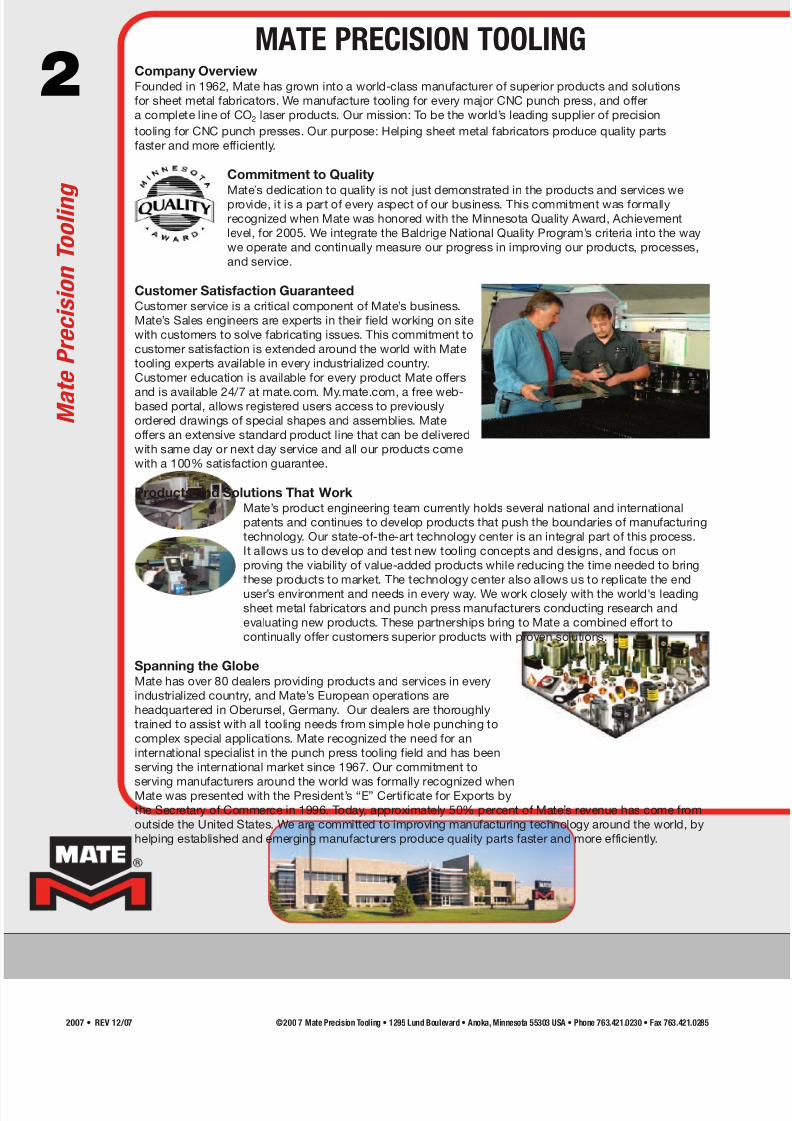
2 Company OverviewFounded in 1962, Mate has grown into a world-class manufacturer of superior products and solutions
for sheet metal fabricators. We manufacture tooling for every major CNC punch press, and offer
a complete line of CO2 laser products. Our mission: To be the world’s leading supplier of precision
tooling for CNC punch presses. Our purpose: Helping sheet metal fabricators produce quality parts
faster and more efficiently.
Commitment to Quality
Mate’s dedication to quality is not just demonstrated in the products and services weprovide, it is a part of every aspect of our business. This commitment was formally
recognized when Mate was honored with the Minnesota Quality Award, Achievement
level, for 2005. We integrate the Baldrige National Quality Program’s criteria into the way
we operate and continually measure our progress in improving our products, processes,
and service.
Customer Satisfaction GuaranteedCustomer service is a critical component of Mate’s business.
Mate’s Sales engineers are experts in their field working on site
with customers to solve fabricating issues. This commitment to
customer satisfaction is extended around the world with Mate
tooling experts available in every industrialized country.
Customer education is available for every product Mate offers
and is available 24/7 at mate.com. My.mate.com, a free web-based portal, allows registered users access to previously
ordered drawings of special shapes and assemblies. Mate
offers an extensive standard product line that can be delivered
with same day or next day service and all our products come
with a 100% satisfaction guarantee.
Products and Solutions That WorkMate’s product engineering team currently holds several national and international
patents and continues to develop products that push the boundaries of manufacturing
technology. Our state-of-the-art technology center is an integral part of this process.
It allows us to develop and test new tooling concepts and designs, and focus on
proving the viability of value-added products while reducing the time needed to bring
these products to market. The technology center also allows us to replicate the end
user’s environment and needs in every way. We work closely with the world's leadingsheet metal fabricators and punch press manufacturers conducting research and
evaluating new products. These partnerships bring to Mate a combined effort to
continually offer customers superior products with proven solutions.
Spanning the GlobeMate has over 80 dealers providing products and services in every
industrialized country, and Mate’s European operations are
headquartered in Oberursel, Germany. Our dealers are thoroughly
trained to assist with all tooling needs from simple hole punching to
complex special applications. Mate recognized the need for an
international specialist in the punch press tooling field and has been
serving the international market since 1967. Our commitment to
serving manufacturers around the world was formally recognized whenMate was presented with the President’s “E” Certificate for Exports by
the Secretary of Commerce in 1996. Today, approximately 50% percent of Mate’s revenue has come from
outside the United States. We are committed to improving manufacturing technology around the world, by
helping established and emerging manufacturers produce quality parts faster and more efficiently.
M a t e P r e c i s i o n T o o l i n g
MATE PRECISION TOOLING
©200 7 Mate Precision Tooling • 1295 Lund Boulevard • Anoka, Minnesota 55303 USA • Phone 763.421.0230 • Fax 763.421.02852007 • REV 12/07

7/30/2019 Catalog Ultrafsdfsdf Tec
http://slidepdf.com/reader/full/catalog-ultrafsdfsdf-tec 3/96
3Ultra TEC® Tooling System Section 1
Thick Turret Tooling Systems Overview 4-5
Features and Benefits 6-7
System Overview 8-9
Ultra TEC® 1/2" A Station Punch Assembly
for Ultra TEC® and Thick Turret Style Punches 10
Ultra TEC® 1-1/4" B Station Punch Assemblyfor Ultra TEC® and Thick Turret Style Punches 11
Ultra TEC® Guide Assemblies for Thick Turret Style Punches 12
Mate Slug Free® Dies 13
Ultra TEC® Fully Guided Section 2
Features and Benefits 14-15
Ultra TEC® Fully Guided 16-17
Ultra TEC® Fully Guided Clamp Clearing Slitting Tool
for 3-1/2" D and 4-1/2" E Station 18
Ultra TEC® Fully Guided Clamp Clearing 19
Ultra XT™ Tooling System Section 3
Features and Benefits 20-21
System Overview 22-23
Ultra XT™ 1/2" A Station Punch Assembly
for Ultra TEC® and Thick Turret Style Punches 24
Ultra XT™ 1-1/4" B Station Punch Assembly
for Ultra TEC® and Thick Turret Style Punches 25
Ultra XT™ Guide Assemblies for Thick Turret Style Punches 26
Ultra TEC® LVD Style Punch Guide Assemblies 27
Original Thick Turret Tooling System Section 4
Features and Benefits 28-29
System Overview 30
Side by Side Comparison 311/2" A Station Assembly 32
1-1/4" B Station Assembly 33
2" C Station Assembly 34
3-1/2" D Station Assembly 35
4-1/2" Station Assembly 36
6" F Station Assembly 37
Special Applications Section 5
Ultra TEC® Heavy Duty 38-39
Ultra LIGHT™ Tooling System Canisters and Spring Packs 40
Thick Turret Punch Guide Assemblies
with Ultra LIGHT™ Spring Packs 41
MXC™ Tooling System 42-43Thick Turret Inch Style Punches with 1/2-13 Threads
2" C, 3-1/2" D, and 4-1/2" E Station 44
Ultra TEC® Guide Assemblies with M14 Bolts 45
Ultra ABS® Tooling System Section 6
Ultra ABS® 1/2" A Station 46
Ultra ABS® 1-1/4" B Station 47
Ultra ABS® Guide Assemblies for Thick Turret Style Punches 48
Ultra ABS® Fully Guided Clamp Clearing 49
Ultra ABS® Fully Guided 50
Ultra ABS® Heavy Duty 51
Accessories Section 7
Thick Turret and Ultra® Accessories 52-53
Thick Turret and Ultra TEC® Adapters 54
Ultra TEC® Field Service Kits 55
Thick Turret Tooling Cabinets 56
Mate Pilot™ Turret Calibration System 57
Special Assemblies Section 8
Ultraform Features and Benefits 58
Ultraform System Overview 59
Special Assemblies 60-70Original Style 1-1/4" B Station Forming Tools 71
Technical Data Section 9
Die Clearance 72
Calculating Punching Force 73
Critical Dimensions 74
Punch and Die Maintenance 75-76
Productivity Improvement Tips and Techniques 77-84
Multi Tool Tooling Systems 85
Ultra TEC® and Ultra ABS® Tool Lubrication System 86-87
Ultra TEC® and Ultra ABS® Grind Life Comparison
1/2" A Station 88
Ultra TEC® and Ultra ABS® Grind Life Comparison1-1/4 B Station 89
Ultra TEC® and Ultra ABS® Grind Life Comparison
2" C, 3-1/2" D, and 4-1/2" E Station 90
Thick Turret Tooling System Compatibility 91
Maxima® Coating and Nitride Treatment 92
M4PM™ Tool Steel 93
Add-Ons 94
Thick Turret Tooling System Quick Reference Price Guide 95
SECTION 1
SECTION 2
SECTION 3
SECTION 4
SECTION 5
SECTION 6
SECTION 7
SECTION 8
SECTION 9
TABLE OF CONTENTS
T a b l e o f C o n t e n t s
©200 7 Mate Precision Tooling • 1295 Lund Boulevard • Anoka,Minnesota 55303 USA • Phone 763.421.0230 • Fax 763.421.0285 2007 • REV 12/07
7/30/2019 Catalog Ultrafsdfsdf Tec
http://slidepdf.com/reader/full/catalog-ultrafsdfsdf-tec 4/96
4
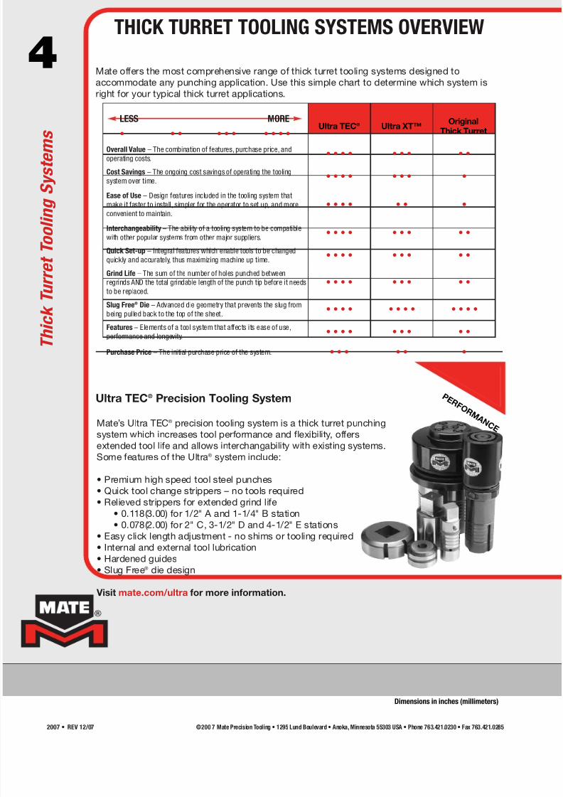
LESS MORE
• • • • • • • • • •Ultra TEC® Ultra XT™
OriginalThick Turret
Overall Value – The combination of features, purchase price, and
operating costs.• • • • • • • • •
Cost Savings – The ongoing cost savings of operating the tooling
system over time.• • • • • • • •
Ease of Use – Design features included in the tooling system that
make it faster to install, simpler for the operator to set up, and more
convenient to maintain.• • • • • • •
Interchangeability – The ability of a tooling system to be compatible
with other popular systems from other major suppliers.• • • • • • • • •
Quick Set-up – Integral features which enable tools to be changed
quickly and accurately, thus maximizing machine up time.• • • • • • • • •
Grind Life – The sum of the number of holes punched between
regrinds AND the total grindable length of the punch tip before it needs
to be replaced.• • • • • • • • •
Slug Free® Die – Advanced die geometry that prevents the slug from
being pulled back to the top of the sheet.• • • • • • • • • • • •
Features – Elements of a tool system that affects its ease of use,
performance and longevity.• • • • • • • • •
Purchase Price – The initial purchase price of the system. • • • • • •
Mate offers the most comprehensive range of thick turret tooling systems designed to
accommodate any punching application. Use this simple chart to determine which system is
right for your typical thick turret applications.
Mate’s Ultra TEC® precision tooling system is a thick turret punching
system which increases tool performance and flexibility, offers
extended tool life and allows interchangability with existing systems.
Some features of the Ultra® system include:
• Premium high speed tool steel punches
• Quick tool change strippers – no tools required
• Relieved strippers for extended grind life
• 0.118(3.00) for 1/2" A and 1-1/4" B station
• 0.078(2.00) for 2" C, 3-1/2" D and 4-1/2" E stations
• Easy click length adjustment - no shims or tooling required
• Internal and external tool lubrication
• Hardened guides• Slug Free® die design
Visit mate.com/ultra for more information.
Ultra TEC® Precision Tooling System P E R F O R
M A N C E
T h i c k T u r r e t T o o l i n g S y s t e m s
THICK TURRET TOOLING SYSTEMS OVERVIEW
Dimensions in inches (millimeters)
©200 7 Mate Precision Tooling • 1295 Lund Boulevard • Anoka, Minnesota 55303 USA • Phone 763.421.0230 • Fax 763.421.02852007 • REV 12/07
7/30/2019 Catalog Ultrafsdfsdf Tec
http://slidepdf.com/reader/full/catalog-ultrafsdfsdf-tec 5/96
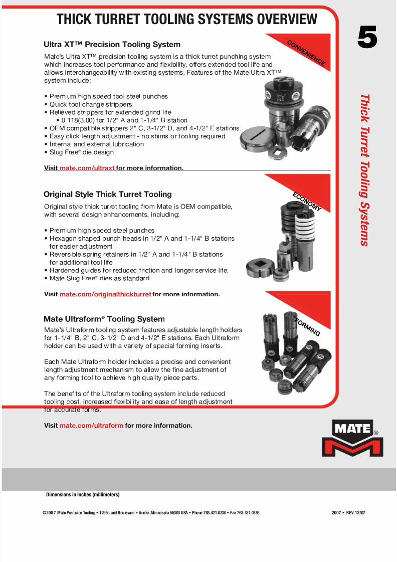
5Ultra XT™ Precision Tooling SystemC O N V E N I E N C E
Mate Ultraform® Tooling System
Original style thick turret tooling from Mate is OEM compatible,
with several design enhancements, including:
• Premium high speed steel punches
• Hexagon shaped punch heads in 1/2" A and 1-1/4" B stations
for easier adjustment
• Reversible spring retainers in 1/2" A and 1-1/4" B stations
for additional tool life
• Hardened guides for reduced friction and longer service life.
• Mate Slug Free® dies as standard
Visit mate.com/originalthickturret for more information.
Original Style Thick Turret Tooling E C O N O M Y
Mate’s Ultraform tooling system features adjustable length holders
for 1-1/4" B, 2" C, 3-1/2" D and 4-1/2" E stations. Each Ultraform
holder can be used with a variety of special forming inserts.
Each Mate Ultraform holder includes a precise and convenient
length adjustment mechanism to allow the fine adjustment of
any forming tool to achieve high quality piece parts.
The benefits of the Ultraform tooling system include reducedtooling cost, increased flexibility and ease of length adjustment
for accurate forms.
Visit mate.com/ultraform for more information.
F O R M I N G
Mate’s Ultra XT™ precision tooling system is a thick turret punching system
which increases tool performance and flexibility, offers extended tool life and
allows interchangeability with existing systems. Features of the Mate Ultra XT™
system include:
• Premium high speed tool steel punches• Quick tool change strippers
• Relieved strippers for extended grind life
• 0.118(3.00) for 1/2" A and 1-1/4" B station
• OEM compatible strippers 2" C, 3-1/2" D, and 4-1/2" E stations.
• Easy click length adjustment - no shims or tooling required
• Internal and external lubrication
• Slug Free® die design
Visit mate.com/ultraxt for more information.
THICK TURRET TOOLING SYSTEMS OVERVIEW
T h i c k T u r r e t T o o l i n g S y s t e m s
Dimensions in inches (millimeters)
©200 7 Mate Precision Tooling • 1295 Lund Boulevard • Anoka,Minnesota 55303 USA • Phone 763.421.0230 • Fax 763.421.0285 2007 • REV 12/07
7/30/2019 Catalog Ultrafsdfsdf Tec
http://slidepdf.com/reader/full/catalog-ultrafsdfsdf-tec 6/96
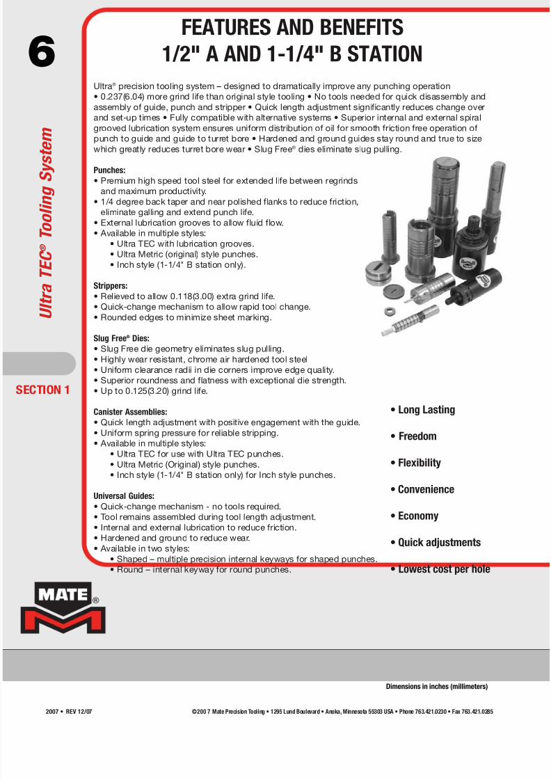
6Ultra® precision tooling system – designed to dramatically improve any punching operation
• 0.237(6.04) more grind life than original style tooling • No tools needed for quick disassembly and
assembly of guide, punch and stripper • Quick length adjustment significantly reduces change over
and set-up times • Fully compatible with alternative systems • Superior internal and external spiral
grooved lubrication system ensures uniform distribution of oil for smooth friction free operation of
punch to guide and guide to turret bore • Hardened and ground guides stay round and true to sizewhich greatly reduces turret bore wear • Slug Free® dies eliminate slug pulling.
Punches:
• Premium high speed tool steel for extended life between regrinds
and maximum productivity.
• 1/4 degree back taper and near polished flanks to reduce friction,
eliminate galling and extend punch life.
• External lubrication grooves to allow fluid flow.
• Available in multiple styles:
• Ultra TEC with lubrication grooves.
• Ultra Metric (original) style punches.
• Inch style (1-1/4" B station only).
Strippers:
• Relieved to allow 0.118(3.00) extra grind life.
• Quick-change mechanism to allow rapid tool change.
• Rounded edges to minimize sheet marking.
Slug Free® Dies:
• Slug Free die geometry eliminates slug pulling.
• Highly wear resistant, chrome air hardened tool steel
• Uniform clearance radii in die corners improve edge quality.
• Superior roundness and flatness with exceptional die strength.
• Up to 0.125(3.20) grind life.
Canister Assemblies:• Quick length adjustment with positive engagement with the guide.
• Uniform spring pressure for reliable stripping.
• Available in multiple styles:
• Ultra TEC for use with Ultra TEC punches.
• Ultra Metric (Original) style punches.
• Inch style (1-1/4" B station only) for Inch style punches.
Universal Guides:
• Quick-change mechanism - no tools required.
• Tool remains assembled during tool length adjustment.
• Internal and external lubrication to reduce friction.
• Hardened and ground to reduce wear.
• Available in two styles:• Shaped – multiple precision internal keyways for shaped punches.
• Round – internal keyway for round punches.
• Long Lasting
• Freedom
• Flexibility
• Convenience
• Economy
• Quick adjustments
• Lowest cost per hole
ECTION 1
U l t r a T E C ® T o o l i n g S y s t e m
FEATURES AND BENEFITS
1/2" A AND 1-1/4" B STATION
Dimensions in inches (millimeters)
©200 7 Mate Precision Tooling • 1295 Lund Boulevard • Anoka, Minnesota 55303 USA • Phone 763.421.0230 • Fax 763.421.02852007 • REV 12/07

7/30/2019 Catalog Ultrafsdfsdf Tec
http://slidepdf.com/reader/full/catalog-ultrafsdfsdf-tec 7/96
7Ultra® precision tooling system – designed to dramatically improve any punching operation
• 0.212(5.38) more punch grind life than original style tooling • Quick change strippers
• Quick length adjustment • Internal lubrication within punch guide • External lubrication between
guide and turret bore ensures uniform distribution of oil within the turret bore • Hardened guides
to reduce turret bore wear • Slug Free® dies eliminate slug pulling.
Punches:
• Premium high speed tool steel for extended life
between regrinds and maximum productivity.
• 1/4 degree back taper and near polished flanks to
reduce friction and eliminate galling.
• Superior angularity, concentricity, and dimensional
accuracy.
• Robust full-body design.
• Fully compatible with original style thick turret tooling.
Strippers:
• Relieved to allow 0.078(2.00) extra grind life.• Recessed to allow collection of lubrication fluid at
punch tip.
• Quick-change mechanism to allow rapid tool change.
• Rounded edges to minimize sheet marking.
• Optional urethane stripper pads to eliminate sheet
marking.
Slug Free® Dies:
• Highly wear resistant, chrome air hardened tool steel to balance
hardness and toughness.
• Slug Free die geometry eliminates slug pulling.
• Uniform clearance radii in die corners to improve edge quality.
• Precision orientation keyway.• Up to 0.125(3.20) grind life.
• Superior roundness and flatness with exceptional die strength.
Punch Guide Assembly:
• Quick-change stripper release mechanism allows stripper to be
removed easily, without tools.
• Quick length adjustment mechanism on the side of the guide
allows the punch length to be adjusted without disassembly.
• Hardened and ground to stay round and true to size to greatly
reduce turret bore wear.
• Internal and external lubrication grooves to reduce friction.
• High performance disc springs to optimize stripping force
throughout the service life of the machine.
Visit mate.com/ultra for more information.
SECTION 1
FEATURES AND BENEFITS
2" C, 3-1/2" D, AND 4-1/2" E STATION
U l t r a T E C ®T o o l i n g S y s t e m
Dimensions in inches (millimeters)
©200 7 Mate Precision Tooling • 1295 Lund Boulevard • Anoka,Minnesota 55303 USA • Phone 763.421.0230 • Fax 763.421.0285 2007 • REV 12/07

7/30/2019 Catalog Ultrafsdfsdf Tec
http://slidepdf.com/reader/full/catalog-ultrafsdfsdf-tec 8/96
8® ® ®
®®
UltraTEC®
Canister AssemblyStandard
Ultra TEC®
Stripper Plate with0.118(3.00) Relief
Ultra TEC®
Punch GuideUltraTEC®
Punch Guide
Ultra TEC®
Stripper PlateUltraTEC®
Stripper Plate Amada Original Style
Stripper PlateHP (Series 90)Stripper Plate
Ultra TEC®
Canister Assembly
Metric
Ultra TEC®
Canister AssemblyStandard
Ultra TEC®
Canister Assembly
Metric
Ultra TEC®
Canister Assembly Inch
UltraTEC®
PunchHP (Series 90)
PunchInch Style
PunchMetric (Original)
Style PunchMetric (Original)
Style Punch
1/2" A STATION 1-1/4" B STATION
Die ShimDie Shim
Ultra TEC®
Punch
Slug Free® Die Slug Free® Die
Features include:
• Extended grind life • Interchangeable components
• Multiple angle settings • Quick length adjustment
• Quick tool change • Premium high speed tool steel punches • Slug Free® die
Ultra TEC®
Punch GuideRound Only
Ultra TEC®
Punch GuideRound Only
ECTION 1
U l t r a T E C ® T o o l i n g S y s t e m
SYSTEM OVERVIEW
Dimensions in inches (millimeters)
©200 7 Mate Precision Tooling • 1295 Lund Boulevard • Anoka, Minnesota 55303 USA • Phone 763.421.0230 • Fax 763.421.02852007 • REV 12/07

7/30/2019 Catalog Ultrafsdfsdf Tec
http://slidepdf.com/reader/full/catalog-ultrafsdfsdf-tec 9/96
9®
®®
Ultra TEC®
Guide AssemblyUltra TEC®
Guide AssemblyUltra TEC®
Guide Assembly
Original Style PunchBody
Original StylePunch Body
Original StylePunch Body
Amada OriginalStyle Punch Body
Amada OriginalStyle Punch Body
HP (Series 90)*Punch Adapter
HP (Series 90)*PunchAdapter
HP (Series 90)*Punch Body
HP (Series 90)*Punch Body
Ultra TEC®
Stripper PlateUltra TEC®
Stripper PlateUltra TEC®
Stripper Plate
2" C STATION
Slug Free® Die Slug Free® Die Slug Free® Die
Die Shim Die Shim Die Shim
3-1/2" D STATION 4-1/2" E STATION
Amada OriginalStyle Punch Body
HP (Series 90)*PunchAdapter
HP (Series 90)*Punch Body
Features include:
• Extended grind life • Interchangeable components
• Multiple angle settings • Quick length adjustment
• Quick tool change • Premium high speed tool steel punches • Slug Free® die
SECTION 1
*Fully Compatiblewith Mate MXC™.See pages 42-43.
SYSTEM OVERVIEW
U l t r a T E C ®T o o l i n g S y s t e m
©200 7 Mate Precision Tooling • 1295 Lund Boulevard • Anoka,Minnesota 55303 USA • Phone 763.421.0230 • Fax 763.421.0285 2007 • REV 12/07
7/30/2019 Catalog Ultrafsdfsdf Tec
http://slidepdf.com/reader/full/catalog-ultrafsdfsdf-tec 10/96
10
®
®
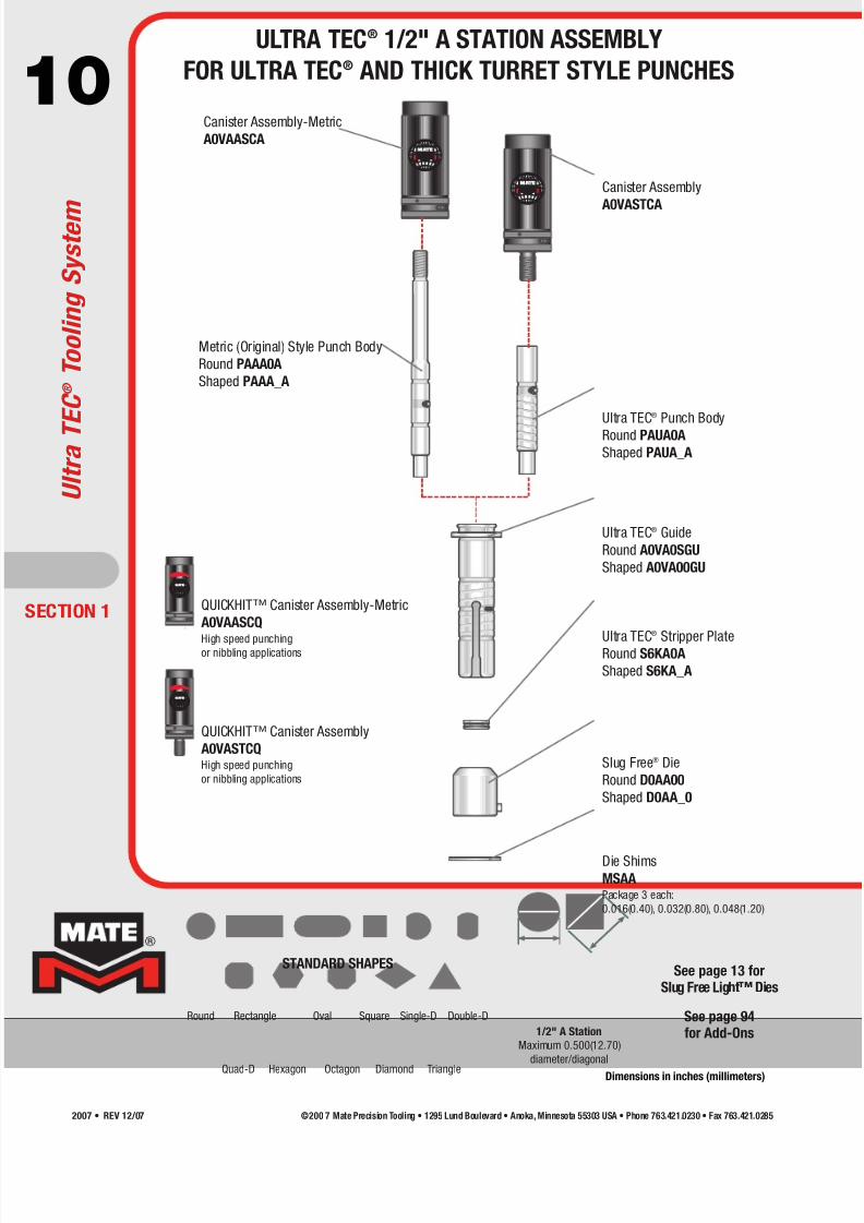
QUICKHIT™ Canister Assembly-Metric
A0VAASCQ
High speed punchingor nibbling applications
®
QUICKHIT™ Canister Assembly
A0VASTCQHigh speed punching
or nibbling applications
®
1/2" A Station
Maximum 0.500(12.70)
diameter/diagonal
Round Rectangle Oval Square Single-D Double-D
Quad-D TriangleHexagon Octagon Diamond
STANDARD SHAPES
ECTION 1
See page 13 forSlug Free Light™ Dies
Canister Assembly-Metric
A0VAASCA
Canister Assembly
A0VASTCA
Metric (Original) Style Punch Body
Round PAAA0A
Shaped PAAA_A
Ultra TEC® Punch Body
Round PAUA0A
Shaped PAUA_A
Ultra TEC® Guide
Round A0VA0SGU
Shaped A0VA00GU
Ultra TEC
®
Stripper PlateRound S6KA0A
Shaped S6KA_A
Slug Free® Die
Round D0AA00
Shaped D0AA_0
Die ShimsMSAAPackage 3 each:
0.016(0.40), 0.032(0.80), 0.048(1.20)
U l t r a T E C ® T o o l i n g S y s t e m
ULTRA TEC® 1/2" A STATION ASSEMBLY
FOR ULTRA TEC® AND THICK TURRET STYLE PUNCHES
See page 94for Add-Ons
Dimensions in inches (millimeters)
©200 7 Mate Precision Tooling • 1295 Lund Boulevard • Anoka, Minnesota 55303 USA • Phone 763.421.0230 • Fax 763.421.02852007 • REV 12/07

7/30/2019 Catalog Ultrafsdfsdf Tec
http://slidepdf.com/reader/full/catalog-ultrafsdfsdf-tec 11/96
11
®
®
®
®
®
®
See page 94for Add-Ons 1-1/4" B Station
Maximum 1.250(31.75)
diameter/diagonal
Round Rectangle Oval Square Single-D Double-D
Quad-D TriangleHexagon Octagon Diamond
STANDARD SHAPES
SECTION 1
See page 13 forSlug Free Light™ Dies
Die Shims
MSABPackage 3 each:
0.016(0.40), 0.032(0.80), 0.048(1.20)
QUICKHIT™ Canister Assembly
A0VBSTCQHigh speed punching
or nibbling applications
QUICKHIT™ Canister Assembly-Inch
A0VBWSCQHigh speed punching
or nibbling applications
QUICKHIT™ Canister Assembly-Metric
A0VBASCQHigh speed punching
or nibbling applications
Canister Assembly-Metric
A0VBASCA
Canister Assembly-Inch
A0VBWSCA
Canister Assembly
A0VBSTCA
Metric (Original) Style Punch Body
Round PAAB0A
Shaped PAAB_A
Inch Style Punch Body
Round PAJB0A
Shaped PAJB_A
Ultra TEC® Punch Body
Round PAUB0A
Shaped PAUB_A
Ultra TEC® Punch Guide
Round A0VB0SGU
Shaped A0VB00GU
Ultra TEC® Stripper Plate
Round S6KB0A
Shaped S6KB_A
Slug Free® Die
Round D0AB00
Shaped D0AB_0
ULTRA TEC® 1-1/4" B STATION ASSEMBLY
FOR ULTRA TEC® AND THICK TURRET STYLE PUNCHES
U l t r a T E C ®T o o l i n g S y s t e m
Dimensions in inches (millimeters)
©200 7 Mate Precision Tooling • 1295 Lund Boulevard • Anoka,Minnesota 55303 USA • Phone 763.421.0230 • Fax 763.421.0285 2007 • REV 12/07
7/30/2019 Catalog Ultrafsdfsdf Tec
http://slidepdf.com/reader/full/catalog-ultrafsdfsdf-tec 12/96
12
®®
®
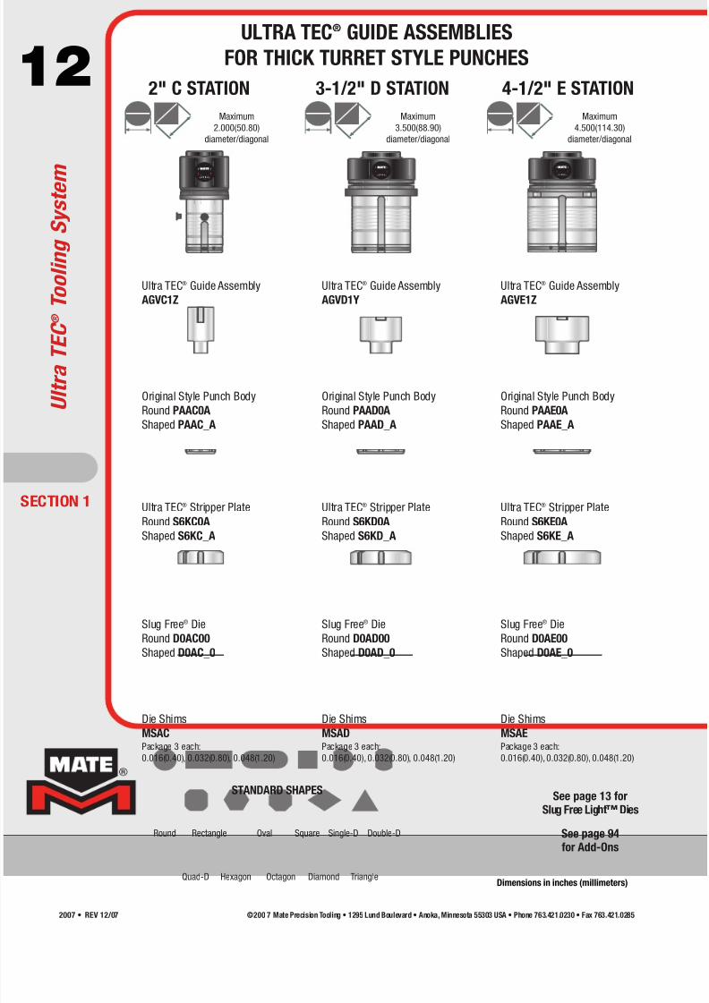
Maximum
2.000(50.80)
diameter/diagonal
Maximum
3.500(88.90)
diameter/diagonal
Maximum
4.500(114.30)
diameter/diagonal
2" C STATION 3-1/2" D STATION 4-1/2" E STATION
Die Shims
MSACPackage 3 each:
0.016(0.40), 0.032(0.80), 0.048(1.20)
Ultra TEC® Guide Assembly
AGVC1Z
Original Style Punch Body
Round PAAC0A
Shaped PAAC_A
Ultra TEC® Stripper Plate
Round S6KC0AShaped S6KC_A
Slug Free® Die
Round D0AC00
Shaped D0AC_0
Die Shims
MSADPackage 3 each:
0.016(0.40), 0.032(0.80), 0.048(1.20)
Ultra TEC® Guide Assembly
AGVD1Y
Original Style Punch Body
Round PAAD0A
Shaped PAAD_A
Ultra TEC® Stripper Plate
Round S6KD0AShaped S6KD_A
Slug Free® Die
Round D0AD00
Shaped D0AD_0
Die Shims
MSAEPackage 3 each:
0.016(0.40), 0.032(0.80), 0.048(1.20)
Ultra TEC® Guide Assembly
AGVE1Z
Original Style Punch Body
Round PAAE0A
Shaped PAAE_A
Ultra TEC® Stripper Plate
Round S6KE0AShaped S6KE_A
Slug Free® Die
Round D0AE00
Shaped D0AE_0
Round Rectangle Oval Square Single-D Double-D
Quad-D TriangleHexagon Octagon Diamond
STANDARD SHAPESSee page 13 for
Slug Free Light™ Dies
ULTRA TEC® GUIDE ASSEMBLIES
FOR THICK TURRET STYLE PUNCHES
Dimensions in inches (millimeters)
See page 94for Add-Ons
ECTION 1
U l t r a T E C ® T o o l i n g S y s t e m
©200 7 Mate Precision Tooling • 1295 Lund Boulevard • Anoka, Minnesota 55303 USA • Phone 763.421.0230 • Fax 763.421.02852007 • REV 12/07

7/30/2019 Catalog Ultrafsdfsdf Tec
http://slidepdf.com/reader/full/catalog-ultrafsdfsdf-tec 13/96
13Mate Slug Free® dies eliminate slug pulling. Slug pulling is a condition where the slug returns to
the top of the sheet during the stripping portion of the punching cycle. The slug comes
between the punch and the top of the sheet on the next cycle. This causes damage to the
piece part and the tooling. Slug Free dies eliminate this problem.
The Slug Free die has been designed with an opening that has a constriction point below the
surface so the slug cannot return once it passes this point. Once the slug is separated from thepunch, it is free to fall away from the punching area. Slug pulling is eliminated.
Material held securely by
stripper before
punch makes contact.
Punch penetrates the
material. Slug fractures
away from sheet.
Pressure point constricts
slug. Punch stroke bottoms
out as slug squeezes past
pressure point.
Punch retracts and slug is
free to fall down and away
through exit taper of the
Slug Free® die.
Mate Slug Free® Dies
Mate Slug Free Light™ thick turret dies are designed toeliminate slug pulling when punching thin sheet metal material,
where the recommended die clearance is less than 0.008(0.20).
The Mate Slug Free Light die works by introducing a series of
small protrusions around the edge of the slug. Each protrusion
is created by a small angled notch cut into the die opening (See
photo 1). As the slug passes through the die, the position of the
protrusion relative to the notch changes slightly. This change
creates slight pressure between the slug and the die land, which
traps the slug into the die and eliminates the possibility of the
slug being pulled back through the die. By eliminating slug
pulling with every punch cycle, the piece part quality is
improved and tool life is increased.
Mate Slug Free Light dies are available for thick turret tooling
and are particularly effective when the die clearance is less
than 0.008(0.20).
Mate Slug Free Light™ Dies for Thin Sheet Metal
Photo 1: Mate Slug Free Light™
notches are cut at an angle to
create a series of protrusions on
the slug. As the slug moves
through the die, the protrusionsbecome trapped against the die
land to prevent the slug pulling
back on to the sheet. (Image
enhanced for additional clarity)
• Eliminate slug pulling
• Reduce tool breakage
• Improve tool life
• Increase quality
MATE SLUG FREE® DIES
Dimensions in inches (millimeters)
SECTION 1
M a t e S l u g F r e e ®D i e s
©200 7 Mate Precision Tooling • 1295 Lund Boulevard • Anoka,Minnesota 55303 USA • Phone 763.421.0230 • Fax 763.421.0285 2007 • REV 12/07

7/30/2019 Catalog Ultrafsdfsdf Tec
http://slidepdf.com/reader/full/catalog-ultrafsdfsdf-tec 14/96
14®®
®
®
• Fully guided assembly Accurate and close tolerances between guide and stripper hold punches rigid, control against hole distortion and saw toothing.
• Premium high speed tool steel punches at 60-62 Rockwell CSpecially formulated high speed steel and specially developed heat treatment processes result in unusually high tool performance, superiordimensional accuracy and maximum tool life.
• Stripper opening 0.0015(0.04) TC to pointGuiding at punch point supports punches, increases hole accuracy, improves stripping and prevents scrap from rising into the assembly.
• Quick length adjustmentThe external quick length adjustment button on the side of the guide allows the punch length to be adjusted without disassembly.
• Hardened and ground guideReduces abrasive action of punching, diffuses heat effectively, resists galling, extends tool life, increases turret life and improves up time.
• Interior and exterior spiral grease groovesEven and consistent tool lubrication increases tool life.
• Tool LubricationInterior vertical fluid grooves and fluid through holes provide even and efficient transfer of lubrication fluid to internal surfaces and toexternal guide surface area, increases lubrication and tool life.
• Slug Free® die designClearing the slug every cycle eliminates slug pulling, extends tool life, improves piece part quality and reduces scrap.
Fully GuidedGuideAssembly
Original StylePunch Body
UltraTEC® Fully GuidedStripper Plate
Slug Free® Die
Fully GuidedGuide Assembly
Original StylePunch Body
Ultra TEC® Fully GuidedStripper Plate
Slug Free® Die
Fully GuidedGuide Assembly
Original StylePunch Body
Ultra TEC® Fully GuidedStripper Plate
Ultra TEC® Fully GuidedStripper Plate
Ultra TEC® Fully GuidedPunch Guide
®
UltraTEC® Canister
Assembly MetricUltra TEC® Canister Assembly Standard
Slug Free® DieSlug Free® Die
2" C
STATION
3-1/2" D
STATION
4-1/2" E
STATION
1-1/4" B
STATION
UltraTEC®
Punch
Metric (Original) StylePunch
ECTION 2
U l t r a T E C ® F u l l y G u i d e d
FEATURES AND BENEFITS
Dimensions in inches (millimeters)
©200 7 Mate Precision Tooling • 1295 Lund Boulevard • Anoka, Minnesota 55303 USA • Phone 763.421.0230 • Fax 763.421.02852007 • REV 12/07

7/30/2019 Catalog Ultrafsdfsdf Tec
http://slidepdf.com/reader/full/catalog-ultrafsdfsdf-tec 15/96
15®® • Fully guided assembly
Accurate and close tolerances between guide and stripper hold
punches rigid, control against hole distortion and saw toothing.
• Premium high speed tool steel punches at 60-62 Rockwell C
Specially formulated M4PM™ high speed steel and specially developed
heat treatment processes result in unusually high
tool performance, superior dimensional accuracy and
maximum tool life.
• Stripper opening 0.0015(0.04) TC to point
Guiding at punch point supports punches, increases hole accuracy,
improves stripping and prevents scrap from rising into the assembly.
• Clamp clearing relief
Use this tool close to work holder clamps. The stripper and
the die are relieved so the clamp can pass between the upper
and the lower unit. No need to reposition the clamps, saves
time, improves piece part quality.
• Quick length adjustment
The external quick length adjustment button on the side of the guide
allows the punch length to be adjusted without disassembly. Guide will
adjust punch point length by 0.008(0.20) per click.
• Hardened and ground guide
Reduces abrasive action of punching, diffuses heat effectively,
resists galling, extends tool life, increases turret life and improves
up time.
• Interior and exterior spiral grease grooves
Even and consistent tool lubrication increases tool life.
• Tool Lubrication
Interior vertical fluid grooves and fluid through holes provide
even and efficient transfer of lubrication fluid to internal surfaces
and to external guide surface area, increases lubrication and
tool life.
• Additional 0.079(2.00) punch grind life
Use insert style punches from Mate in combination with this
specially designed stripper to gain additional grind life.
• Slug Free® die design
Clearing the slug every cycle eliminates slug pulling, extendstool life, improves piece part quality and reduces scrap.
UltraTEC® Fully GuidedClamp ClearingGuide Assmbly
Ultra TEC® Fully GuidedClamp ClearingGuide Assmbly
Punch Retainer Punch Retainer
Slitting Insert Slitting Insert
“DD” Stripper Plate “DD” Stripper Plate
“D” Stripper Plate “D” Stripper Plate
“D” Clamp ClearingSlug Free® Die
“D” Clamp ClearingSlug Free® Die
“DD” Clamp ClearingSlug Free® Die
“DD” Clamp ClearingSlug Free® Die
3-1/2" D STATION 4-1/2" E STATION
SECTION 2
FEATURES AND BENEFITS
U l t r a T E C ®F u l l y G u i d e d C l a m p C l e a r i n g
Dimensions in inches (millimeters)
©200 7 Mate Precision Tooling • 1295 Lund Boulevard • Anoka,Minnesota 55303 USA • Phone 763.421.0230 • Fax 763.421.0285 2007 • REV 12/07

7/30/2019 Catalog Ultrafsdfsdf Tec
http://slidepdf.com/reader/full/catalog-ultrafsdfsdf-tec 16/96
16
®
®
1-1/4" B STATION
A clip tool (MIS59723) is
Included in the purchase of an
ULTRA TEC fully guided punch
guide (A0VB00GG).
®
®
1-1/4” B Station
Maximum 1.250(31.75)
diameter/diagonal
ECTION 2
Metric (Original) Style Punch Body
Round PAAB0AShaped PAAB_A
Ultra TEC®
Punch BodyRound PAUB0A
Shaped PAUB_A
Slug Free® Die
Round D0AB00
Shaped D0AB_0
Round Rectangle Oval Square Single-D Double-D
Quad-D TriangleHexagon Octagon Diamond
STANDARD SHAPESSee page 13 for
Slug Free Light™ Dies
Heavy Duty Canister
Assembly-Metric
A0VBHMCARecommended when material
thickness exceeds 0.118(3.00)
Canister Assembly-Metric
A0VBASCA Canister Assembly
A0VBSTCA
Heavy Duty Canister Assembly
A0VBHSCARecommended when material
thickness exceeds 0.118(3.00)
Ultra TEC® Fully Guided
Punch Guide
A0VB00GG
Ultra TEC® Fully Guided
Stripper Plate
Round S6KK0A
Shaped S6KK_A
Clip Tool
MIS59723
U l t r a T E C ® F u l l y G u i d e d
ULTRA TEC® FULLY GUIDED
Dimensions in inches (millimeters)
See page 94for Add-Ons
©200 7 Mate Precision Tooling • 1295 Lund Boulevard • Anoka, Minnesota 55303 USA • Phone 763.421.0230 • Fax 763.421.02852007 • REV 12/07

7/30/2019 Catalog Ultrafsdfsdf Tec
http://slidepdf.com/reader/full/catalog-ultrafsdfsdf-tec 17/96
17®®
®
Maximum
2.000(50.80)
diameter/diagonal
Maximum
3.500(88.90)
diameter/diagonal
Maximum
4.500(114.30)
diameter/diagonal
®
®
Lifter “T” Handle
A0LEH
Round Rectangle Oval Square Single-D Double-D
Quad-D TriangleHexagon Octagon Diamond
STANDARD SHAPES
2" C STATION 3-1/2" D STATION 4-1/2" E STATION
SECTION 2
See page 13 forSlug Free Light™ Dies
Ultra TEC® Fully Guided
Guide Assembly*
AGVS1Z
Original Style Punch Body
Round PAAC0A
Shaped PAAC_A
Fully Guided Stripper Plate
Round S2KL0A
Shaped S2KL_A
Slug Free® Die
Round D0AC00
Shaped D0AC_0
**Also Available(3-1/2" D Station Only)
AGVT3YExternal keyways at
0°, 45° and 90°
Ultra TEC® Fully Guided
Guide Assembly**
AGVT1Y
Original Style Punch Body
Round PAAD0A
Shaped PAAD_A
Fully Guided Stripper Plate
Round S2KM0A
Shaped S2KM_A
Slug Free® Die
Round D0AD00
Shaped D0AD_0
Ultra TEC® Fully Guided
Guide Assembly
AGVU1Z
Original Style Punch Body
Round PAAE0A
Shaped PAAE_A
Fully Guided Stripper Plate
Round S2KN0A
Shaped S2KN_A
Slug Free® Die
Round D0AE00
Shaped D0AE_0
ULTRA TEC® FULLY GUIDED
U l t r a T E C ®F u l l y G
u i d e d
Dimensions in inches (millimeters)
See page 94for Add-Ons
*Also Available(2" C Station Only)
AGVS3ZExternal keyways at
0°, 45° and 90°
©200 7 Mate Precision Tooling • 1295 Lund Boulevard • Anoka,Minnesota 55303 USA • Phone 763.421.0230 • Fax 763.421.0285 2007 • REV 12/07

7/30/2019 Catalog Ultrafsdfsdf Tec
http://slidepdf.com/reader/full/catalog-ultrafsdfsdf-tec 18/96
18ULTRA® CLAMP CLEARING SLITTING TOOL
This tool is specially designed for slitting and parting applications.
Separating piece parts, trimming sheet edges, and reducing sheet
sizes often requires the use of a tool with long narrow dimensions.
Rectangles with radius corners or ovals are recommended.
Slitting and parting applications require the tool to pierce material
cleanly and accurately while overcoming various side load and
twisting pressures. For example, parting a sheet will include an
amount of overlap in each step where sheet resistance is absent.
This causes the force of resistance to build on one side which
can cause the hole to distort or saw tooth.The same is true
when trimming the edge of a sheet.
The Ultra clamp clearing slitting tool is designed to overcome theseside load and twisting pressures. The advantage comes from punch
point guiding. By squarely and tightly controlling the punch point
where it contacts the sheet, the punch can accurately pierce a hole,
even when punching partial hits.
PUNCH
CUT LINE
LAST CUT
NOTCHING OR NIBBLING LESS THAN
2-1/2TIMES SHEET THICKNESS IS NOT
RECOMMENDED.
On excessively thin cuts, metal tends to
bend down into the die opening
instead of shearing cleanly. It will
wedge the punch sideways.This
causes the punch and die to dull
quickly.This is likely to happen when
trying to square a sheet edge to zero
at one end of the cut,as shown here.
STRIPPERPUNCH
MATERIAL
SUPPORT SUPPORT
DIE
®®
UltraTEC® Fully GuidedClamp ClearingGuideAssembly
Ultra TEC® Fully GuidedClamp ClearingGuide Assembly
Punch Retainer Punch Retainer
Slitting Insert Slitting Insert
“DD” Stripper Plate “DD” Stripper Plate
“D” Stripper Plate “D” Stripper Plate
“D” Clamp ClearingSlug Free® Die
“D” Clamp ClearingSlug Free® Die
3-1/2" D STATION 4-1/2" E STATION
“DD” Clamp ClearingSlug Free® Die
“DD” Clamp ClearingSlug Free® Die
ECTION 2
U l t r a T E C ® F u l l y G u i d e d
ULTRA TEC® FULLY GUIDED CLAMP CLEARING
SLITTING TOOL FOR 3-1/2" D AND 4-1/2" E STATION
©200 7 Mate Precision Tooling • 1295 Lund Boulevard • Anoka, Minnesota 55303 USA • Phone 763.421.0230 • Fax 763.421.02852007 • REV 12/07

7/30/2019 Catalog Ultrafsdfsdf Tec
http://slidepdf.com/reader/full/catalog-ultrafsdfsdf-tec 19/96
19
®
®®
4.500(114.30) maximumpunch diagonal/length
0.315(8.00) maximumpunch width
4.560(115.80) maximumdie diagonal/length
0.374(9.50) maximumdie width
3.500(88.90) maximumpunch diagonal/length
0.315(8.00) maximumpunch width
3.560(90.40) maximumdie diagonal/length
0.374(9.50) maximumdie width
Lifter “T” Handle
A0LEH
Rectangle Oval
STANDARD SHAPES
SECTION 2
*Also Available(3-1/2" D Station Only)
AGVT3YExternal keyways at
0°, 45° and 90°
Ultra TEC® Fully Guided
Guide Assembly*
AGVT1Y
Punch Retainer
A0LD00PR
Slitting Insert
Shaped P4AQ_A
Clamp Clearing
“DD” Stripper Plate
Shaped S6KW_A
Clamp Clearing
“D” Stripper Plate
Shaped S6KT_A
Clamp Clearing
“DD” Slug Free® Die
Shaped D0AW_0
Clamp Clearing
“D” Slug Free® Die
Shaped D0AT_0
3-1/2" D STATION 4-1/2" E STATION
Ultra TEC® Fully Guided
Guide Assembly*
AGVU1Z
Punch Retainer
A0LE00PR
Slitting Insert
Shaped P4AR_A
Clamp Clearing
“DD” Stripper Plate
Shaped S6KX_A
Clamp Clearing
“D” Stripper Plate
Shaped S6KU_A
Clamp Clearing
“DD” Slug Free® Die
Shaped D0AX_0
Clamp Clearing
“D” Slug Free® Die
Shaped D0AU_0
ULTRA TEC® FULLY GUIDED CLAMP CLEARING
U l t r a T E C ®F u l l y G
u i d e d
Dimensions in inches (millimeters)
See page 94for Add-Ons
See page 13 forSlug Free Light™ Dies
©200 7 Mate Precision Tooling • 1295 Lund Boulevard • Anoka,Minnesota 55303 USA • Phone 763.421.0230 • Fax 763.421.0285 2007 • REV 12/07
7/30/2019 Catalog Ultrafsdfsdf Tec
http://slidepdf.com/reader/full/catalog-ultrafsdfsdf-tec 20/96
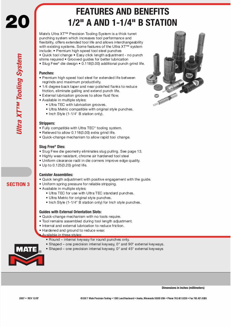
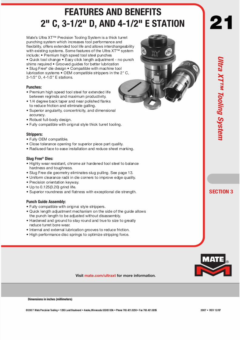
20Mate’s Ultra XT™ Precision Tooling System is a thick turretpunching system which increases tool performance andflexibility, offers extended tool life and allows interchangeabilitywith existing systems. Some features of the Ultra XT™ systeminclude: • Premium high speed tool steel punches• Quick tool change • Easy click length adjustment - no punchshims required • Grooved guides for better lubrication• Slug Free® die design • 0.118(3.00) additional punch grind life.
Punches:• Premium high speed tool steel for extended life between
regrinds and maximum productivity.
• 1/4 degree back taper and near polished flanks to reducefriction, eliminate galling and extend punch life.
• External lubrication grooves to allow fluid flow.
• Available in multiple styles:
• Ultra TEC with lubrication grooves.
• Ultra Metric compatible with original style punches.
• Inch Style (1-1/4" B station only).
Strippers:• Fully compatible with Ultra TEC® tooling system.
• Relieved to allow 0.118(3.00) extra grind life.
• Quick-change mechanism to allow rapid tool change.
Slug Free® Dies:• Slug Free die geometry eliminates slug pulling. See page 13.
• Highly wear resistant, chrome air hardened tool steel
• Uniform clearance radii in die corners improve edge quality.
• Up to 0.125(3.20) grind life.
Canister Assemblies:• Quick length adjustment with positive engagement with the guide.
• Uniform spring pressure for reliable stripping.
• Available in multiple styles:
• Ultra TEC for use with Ultra TEC standard punches.
• Ultra Metric for original style punches.
• Inch Style (1-1/4" B station only) for Inch style punches.
Guides with External Orientation Slots:• Quick-change mechanism with no tools require.
• Tool remains assembled during tool length adjustment.
• Internal and external lubrication to reduce friction.
• Hardened and ground to reduce wear.• Available in three styles:
• Round – internal keyway for round punches only.
• Shaped – one precision internal keyway, 0° and 90° external keyways.
• Shaped – one precision internal keyway, 0° and 45° external keyways
ECTION 3
U l t r a X T ™ T o o l i n g S y s t e m
FEATURES AND BENEFITS
1/2" A AND 1-1/4" B STATION
Dimensions in inches (millimeters)
©200 7 Mate Precision Tooling • 1295 Lund Boulevard • Anoka, Minnesota 55303 USA • Phone 763.421.0230 • Fax 763.421.02852007 • REV 12/07
7/30/2019 Catalog Ultrafsdfsdf Tec
http://slidepdf.com/reader/full/catalog-ultrafsdfsdf-tec 21/96
21
Visit mate.com/ultraxt for more information.
SECTION 3
Mate’s Ultra XT™ Precision Tooling System is a thick turretpunching system which increases tool performance andflexibility, offers extended tool life and allows interchangeabilitywith existing systems. Some features of the Ultra XT™ systeminclude: • Premium high speed tool steel punches
• Quick tool change • Easy click length adjustment - no punchshims required • Grooved guides for better lubrication• Slug Free® die design • Compatible with machine toollubrication systems • OEM compatible strippers in the 2" C,3-1/2" D, 4-1/2" E stations.
Punches:• Premium high speed tool steel for extended life
between regrinds and maximum productivity.
• 1/4 degree back taper and near polished flanksto reduce friction and eliminate galling.
• Superior angularity, concentricity, and dimensionalaccuracy.
• Robust full-body design.• Fully compatible with original style thick turret tooling.
Strippers:• Fully OEM compatible.
• Close tolerance opening for superior piece part quality.
• Radiused face to ease installation and reduce sheet marking.
Slug Free® Dies:• Highly wear resistant, chrome air hardened tool steel to balance
hardness and toughness.
• Slug Free die geometry eliminates slug pulling. See page 13.
• Uniform clearance radii in die corners to improve edge quality.• Precision orientation keyway.
• Up to 0.125(3.20) grind life.
• Superior roundness and flatness with exceptional die strength.
Punch Guide Assembly:• Fully compatible with original style strippers.
• Quick length adjustment mechanism on the side of the guide allowsthe punch length to be adjusted without disassembly.
• Hardened and ground to stay round and true to size to greatlyreduce turret bore wear.
• Internal and external lubrication grooves to reduce friction.
• High performance disc springs to optimize stripping force.
FEATURES AND BENEFITS
2" C, 3-1/2" D, AND 4-1/2" E STATION
U l t r a X T ™T o o l i n
g S y s t e m
Dimensions in inches (millimeters)
©200 7 Mate Precision Tooling • 1295 Lund Boulevard • Anoka,Minnesota 55303 USA • Phone 763.421.0230 • Fax 763.421.0285 2007 • REV 12/07
7/30/2019 Catalog Ultrafsdfsdf Tec
http://slidepdf.com/reader/full/catalog-ultrafsdfsdf-tec 22/96
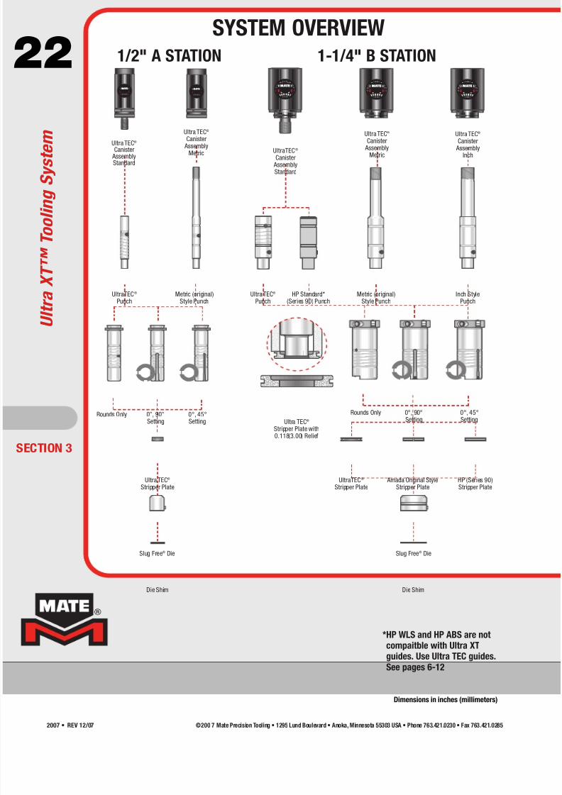
22® ® ®
®®
UltraTEC®
Canister AssemblyStandard
Ultra TEC®
Stripper Plate with0.118(3.00) Relief
UltraTEC®
Stripper PlateUltra TEC®
Stripper Plate Amada Original Style
Stripper PlateHP (Series 90)Stripper Plate
Ultra TEC®
Canister Assembly
Metric
Ultra TEC®
Canister AssemblyStandard
Ultra TEC®
Canister Assembly
Metric
Ultra TEC®
Canister Assembly
Inch
UltraTEC®
PunchHP Standard*
(Series 90) PunchInch Style
PunchMetric (original)
Style PunchMetric (original)
Style Punch
1/2" A STATION 1-1/4" B STATION
Die ShimDie Shim
Ultra TEC®
Punch
Slug Free® Die Slug Free® Die
Rounds Only 0°, 90°Setting
0°, 45°Setting
Rounds Only 0°, 90°
Setting
0°, 45°
Setting
ECTION 3
U l t r a X T ™ T o o l i n g S y s t e m
SYSTEM OVERVIEW
Dimensions in inches (millimeters)
*HP WLS and HP ABS are notcompaitble with Ultra XTguides. Use Ultra TEC guides.
See pages 6-12
©200 7 Mate Precision Tooling • 1295 Lund Boulevard • Anoka, Minnesota 55303 USA • Phone 763.421.0230 • Fax 763.421.02852007 • REV 12/07
7/30/2019 Catalog Ultrafsdfsdf Tec
http://slidepdf.com/reader/full/catalog-ultrafsdfsdf-tec 23/96
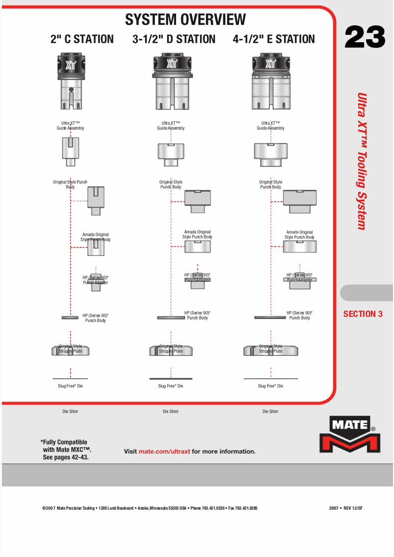
23
Ultra XT™Guide Assembly
Ultra XT™Guide Assembly
Ultra XT™Guide Assembly
Original Style PunchBody
Original StylePunch Body
Original StylePunch Body
Amada OriginalStyle Punch Body
Amada OriginalStyle Punch Body
HP (Series 90)*Punch Adapter
HP (Series 90)*PunchAdapter
HP (Series 90)*Punch Body
HP (Series 90)*Punch Body
Original StyleStripper Plate
Original StyleStripper Plate
Original StyleStripper Plate
2" C STATION
Slug Free® Die Slug Free® Die Slug Free® Die
Die Shim Die Shim Die Shim
3-1/2" D STATION 4-1/2" E STATION
Amada OriginalStyle Punch Body
HP (Series 90)*PunchAdapter
HP (Series 90)*Punch Body
®®
®
SECTION 3
Visit mate.com/ultraxt for more information.
*Fully Compatiblewith Mate MXC™.See pages 42-43.
SYSTEM OVERVIEW
U l t r a X T ™T o o l i n
g S y s t e m
©200 7 Mate Precision Tooling • 1295 Lund Boulevard • Anoka,Minnesota 55303 USA • Phone 763.421.0230 • Fax 763.421.0285 2007 • REV 12/07
7/30/2019 Catalog Ultrafsdfsdf Tec
http://slidepdf.com/reader/full/catalog-ultrafsdfsdf-tec 24/96
24
Rounds
Only
0°, 90°
Setting
®
®
0°, 45°
Setting
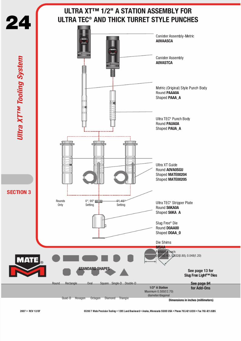
1/2" A Station
Maximum 0.500(12.70)
diameter/diagonal
ECTION 3
Round Rectangle Oval Square Single-D Double-D
Quad-D TriangleHexagon Octagon Diamond
STANDARD SHAPESSee page 13 for
Slug Free Light™ Dies
Canister Assembly-Metric
A0VAASCA
Canister AssemblyA0VASTCA
Metric (Original) Style Punch Body
Round PAAA0A
Shaped PAAA_A
Ultra TEC®
Punch BodyRound PAUA0A
Shaped PAUA_A
Ultra XT Guide
Round A0VA0SGU
Shaped MATE00204
Shaped MATE00205
Ultra TEC® Stripper Plate
Round S6KA0A
Shaped S6KA_A
Slug Free® Die
Round D0AA00
Shaped D0AA_0
Die Shims
MSAAPackage 3 each:
0.016(0.40), 0.032(0.80), 0.048(1.20)
U l t r a X T ™ T o o l i n g S y s t e m
ULTRA XT™ 1/2" A STATION ASSEMBLY FOR
ULTRA TEC® AND THICK TURRET STYLE PUNCHES
Dimensions in inches (millimeters)
See page 94for Add-Ons
©200 7 Mate Precision Tooling • 1295 Lund Boulevard • Anoka, Minnesota 55303 USA • Phone 763.421.0230 • Fax 763.421.02852007 • REV 12/07

7/30/2019 Catalog Ultrafsdfsdf Tec
http://slidepdf.com/reader/full/catalog-ultrafsdfsdf-tec 25/96
25
®
®
®
Rounds
Only
0°, 90°
Setting
0°, 45°
Setting
SECTION 3
1-1/4" B Station
Maximum 1.250(31.75)
diameter/diagonal
Round Rectangle Oval Square Single-D Double-D
Quad-D TriangleHexagon Octagon Diamond
STANDARD SHAPESSee page 13 forSlug Free Light™ Dies
Canister Assembly-Metric
A0VBASCA
Canister AssemblyA0VBSTCA
Metric (Original) Style Punch Body
Round PAAB0A
Shaped PAAB_A
Inch Style Punch Body
Round PAJB0A
Shaped PAJB_A
Ultra XT Guide
Round A0VB0SGU
Shaped MATE00206
Shaped MATE00207
Ultra TEC® Stripper Plate
Round S6KB0A
Shaped S6KB_A
Slug Free® Die
Round D0AB00
Shaped D0AB_0
Die Shims
MSABPackage 3 each:
0.016(0.40), 0.032(0.80), 0.048(1.20)
Canister Assembly-Inch
A0VBWSCA
Ultra TEC® Punch Body
Round PAUB0A
Shaped PAUB_A
ULTRA XT™ 1-1/4" B STATION ASSEMBLY FOR
ULTRA TEC® AND THICK TURRET STYLE PUNCHES
U l t r a X T ™T o o l i n
g S y s t e m
Dimensions in inches (millimeters)
See page 94for Add-Ons
©200 7 Mate Precision Tooling • 1295 Lund Boulevard • Anoka,Minnesota 55303 USA • Phone 763.421.0230 • Fax 763.421.0285 2007 • REV 12/07

7/30/2019 Catalog Ultrafsdfsdf Tec
http://slidepdf.com/reader/full/catalog-ultrafsdfsdf-tec 26/96
26
Ultra XT Guide Assembly
MATE00213
Original Style Punch Body
Round PAAE0A
Shaped PAAE_A
Original Style Stripper Plate
Round S6AE0AShaped S6AE_A
Slug Free® Die
Round D0AE00
Shaped D0AE_0
Die Shims
MSAEPackage 3 each:
0.016(0.40), 0.032(0.80), 0.048(1.20)
Ultra XT Guide Assembly
MATE00211
Original Style Punch Body
Round PAAD0A
Shaped PAAD_A
Original Style Stripper Plate
Round S6AD0AShaped S6AD_A
Slug Free® Die
Round D0AD00
Shaped D0AD_0
Die Shims
MSADPackage 3 each:
0.016(0.40), 0.032(0.80), 0.048(1.20)
®®
®
Maximum
2.000(50.80)
diameter/diagonal
Maximum
3.500(88.90)
diameter/diagonal
Maximum
4.500(114.30)
diameter/diagonal
2" C STATION 3-1/2" D STATION 4-1/2" E STATION
ECTION 3
Round Rectangle Oval Square Single-D Double-D
Quad-D TriangleHexagon Octagon Diamond
STANDARD SHAPESSee page 13 for
Slug Free Light™ Dies
Ultra XT Guide Assembly
MATE00209
Original Style Punch Body
Round PAAC0A
Shaped PAAC_A
Original Style Stripper Plate
Round S6AC0AShaped S6AC_A
Slug Free® Die
Round D0AC00
Shaped D0AC_0
Die Shims
MSACPackage 3 each:
0.016(0.40), 0.032(0.80), 0.048(1.20)
U l t r a X T ™ T o o l i n g S y s t e m
ULTRA XT™ GUIDE ASSEMBLIESFOR THICK TURRET STYLE TOOLING
Dimensions in inches (millimeters)
See page 94for Add-Ons
©200 7 Mate Precision Tooling • 1295 Lund Boulevard • Anoka, Minnesota 55303 USA • Phone 763.421.0230 • Fax 763.421.02852007 • REV 12/07

7/30/2019 Catalog Ultrafsdfsdf Tec
http://slidepdf.com/reader/full/catalog-ultrafsdfsdf-tec 27/96
27
*Also Available(3-1/2" D Station Only)
LGVT3External keyways at
0°, 45° and 90°
Ultra® LVD Guide Assembly
LGVE1
Ultra® LVD Fully Guided
Guide Assembly*
LGVU1
Ultraform® LVD Style Forming Unit
Guide Assembly
LFKE2
Ultra® LVD Guide Assembly
LGVD1
Ultra® LVD Fully Guided
Guide Assembly*
LGVT1
Ultraform® LVD Style Forming Unit
Guide Assembly
LFKD2
*Also Available(2" C Station Only)
LGVS3External keyways at
0°, 45° and 90°
Ultra® LVD Guide Assembly
LGVC1
Ultra® LVD Fully Guided
Guide Assembly*
LGVS1
Ultraform® LVD Style Forming Unit
Guide Assembly
LFKC2
SECTION 3
®®
®
®®
®
®
®
2" C STATION0.250(6.35) wide keyway
3-1/2" D STATION0.512(13.00) wide keyway
4-1/2" E STATION0.512(13.00) wide keyway
Lifter “T” Handle
A0LEH
ULTRA TEC® LVD STYLE PUNCH GUIDE ASSEMBLIES
U l t r a T E C ®T o o l i n g S y s t e m
Dimensions in inches (millimeters)
©200 7 Mate Precision Tooling • 1295 Lund Boulevard • Anoka,Minnesota 55303 USA • Phone 763.421.0230 • Fax 763.421.0285 2007 • REV 12/07

7/30/2019 Catalog Ultrafsdfsdf Tec
http://slidepdf.com/reader/full/catalog-ultrafsdfsdf-tec 28/96
28
ECTION 4
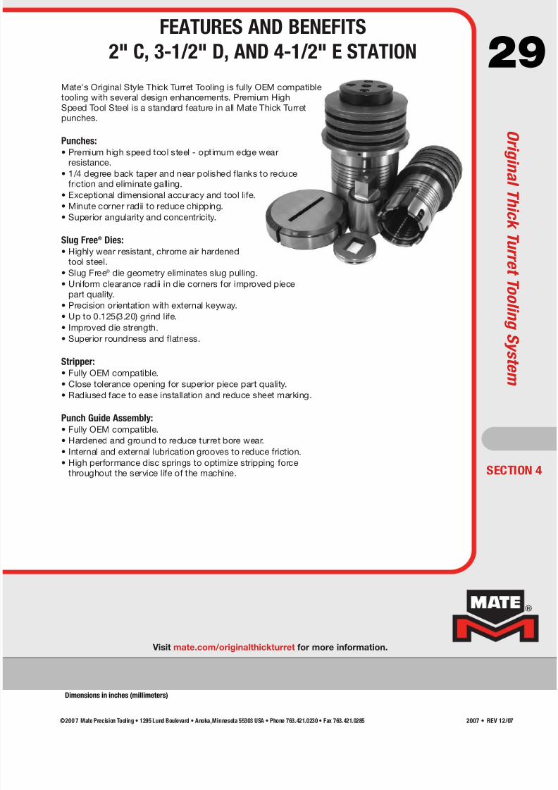
Mate's Original Style Thick Turret Tooling is fully OEM compatibletooling with several design enhancements. Premium High Speed ToolSteel is a standard feature in all Mate Thick Turret punches.
Punches:• Premium high speed tool steel - optimum edge wear resistance.
• 1/4 degree back taper and near polished flanks to reduce frictionand eliminate galling.
• Exceptional dimensional accuracy and tool life.
• Minute corner radii to reduce chipping.
• Superior angularity and concentricity.
Strippers:• Fully OEM compatible.
• Close tolerance opening - superior piece part quality.
• Precision alignment slots - superior piece part quality.
• Hardened and ground - to reduce friction.
• Radiused face - to reduce sheet marking.
Slug Free® Dies:• Highly wear resistant, chrome air hardened tool steel.
• Slug Free® die geometry eliminate slug pulling.
• Uniform clearance radii in die corners for improved piece part quality.
• Precision orientation with hardened pin.
• Up to 0.125(3.20) grind life.
• Improved die strength.
• Superior roundness and flatness.
Punch Head:
• Hexagonal design and 12.9 grade socket head cap screw for easierinstallation and adjustment.
Spring:• High performance spring shot peened prior to painting for extended
service life.
Spring Retainer:• Reversible design returns the punch point to “new” position by
turning over retainer after 0.078(2.00) has been removed duringregrinding.
O r i g i n a l T h i c k T u r r e t T o o l i n g S y s t e m
FEATURES AND BENEFITS
1/2" A AND 1-1/4" B STATION
Dimensions in inches (millimeters)
©200 7 Mate Precision Tooling • 1295 Lund Boulevard • Anoka, Minnesota 55303 USA • Phone 763.421.0230 • Fax 763.421.02852007 • REV 12/07
7/30/2019 Catalog Ultrafsdfsdf Tec
http://slidepdf.com/reader/full/catalog-ultrafsdfsdf-tec 29/96
29
Visit mate.com/originalthickturret for more information.
SECTION 4
Mate's Original Style Thick Turret Tooling is fully OEM compatibletooling with several design enhancements. Premium HighSpeed Tool Steel is a standard feature in all Mate Thick Turretpunches.
Punches:• Premium high speed tool steel - optimum edge wear
resistance.
• 1/4 degree back taper and near polished flanks to reducefriction and eliminate galling.
• Exceptional dimensional accuracy and tool life.
• Minute corner radii to reduce chipping.
• Superior angularity and concentricity.
Slug Free® Dies:• Highly wear resistant, chrome air hardened
tool steel.
• Slug Free
®
die geometry eliminates slug pulling.• Uniform clearance radii in die corners for improved piecepart quality.
• Precision orientation with external keyway.
• Up to 0.125(3.20) grind life.
• Improved die strength.
• Superior roundness and flatness.
Stripper:• Fully OEM compatible.
• Close tolerance opening for superior piece part quality.
• Radiused face to ease installation and reduce sheet marking.
Punch Guide Assembly:• Fully OEM compatible.
• Hardened and ground to reduce turret bore wear.
• Internal and external lubrication grooves to reduce friction.
• High performance disc springs to optimize stripping forcethroughout the service life of the machine.
FEATURES AND BENEFITS
2" C, 3-1/2" D, AND 4-1/2" E STATION
O r i g i n a l T h i c k T u r r e t T o o l i n g S y s t e m
Dimensions in inches (millimeters)
©200 7 Mate Precision Tooling • 1295 Lund Boulevard • Anoka,Minnesota 55303 USA • Phone 763.421.0230 • Fax 763.421.0285 2007 • REV 12/07
7/30/2019 Catalog Ultrafsdfsdf Tec
http://slidepdf.com/reader/full/catalog-ultrafsdfsdf-tec 30/96
30
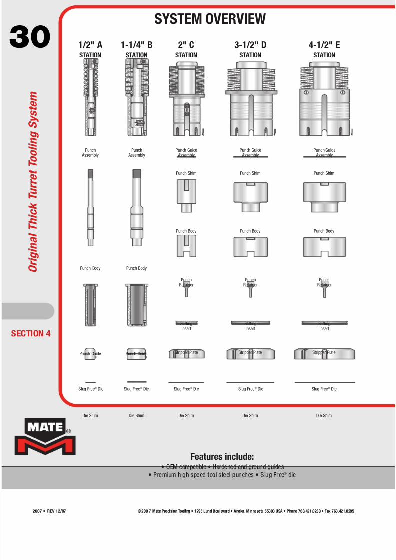
Punch Assembly
Punch Assembly
Punch Guide Assembly
Punch Guide Assembly
Punch Guide Assembly
Punch Body Punch Body
Punch Body Punch Body Punch Body
Punch Guide Punch Guide Stripper Plate Stripper Plate Stripper Plate
Slug Free® Die Slug Free® Die Slug Free® Die Slug Free® Die Slug Free® Die
Die Shim Die Shim Die Shim Die Shim Die Shim
Punch Shim Punch Shim Punch Shim
SlittingInsert
SlittingInsert
SlittingInsert
PunchRetainer
PunchRetainer
PunchRetainer
1/2" ASTATION
1-1/4" BSTATION
2" CSTATION
3-1/2" DSTATION
4-1/2" ESTATION
Features include:• OEM compatible • Hardened and ground guides
• Premium high speed tool steel punches • Slug Free® die
ECTION 4
O r i g i n a l T h i c k T u r r e t T o o l i n g S y s t e m
SYSTEM OVERVIEW
©200 7 Mate Precision Tooling • 1295 Lund Boulevard • Anoka, Minnesota 55303 USA • Phone 763.421.0230 • Fax 763.421.02852007 • REV 12/07
7/30/2019 Catalog Ultrafsdfsdf Tec
http://slidepdf.com/reader/full/catalog-ultrafsdfsdf-tec 31/96
31
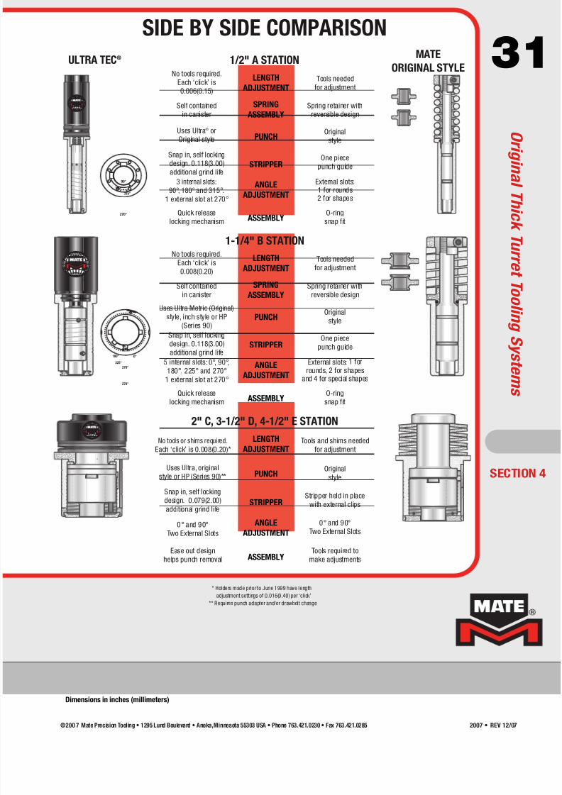
* Holders made priorto June 1999 have length
adjustment settings of 0.016(0.40) per ‘click’
** Requires punch adapter and/or drawbolt change
®
®
®
No tools required.
Each ‘click’ is
0.006(0.15)
Self contained
in canister
Uses Ultra® or
Original style
Snap in, self locking
design. 0.118(3.00)
additional grind life
3 internal slots:
90°, 180° and 315°.
1 external slot at 270°
Quick release
locking mechanism
LENGTH
ADJUSTMENT
SPRING
ASSEMBLY
PUNCH
STRIPPER
ANGLE
ADJUSTMENT
ASSEMBLY
Tools needed
for adjustment
Spring retainer with
reversible design
Original
style
One piece
punch guide
External slots:1 for rounds2 for shapes
O-ring
snap fit
ULTRA TEC® MATE
ORIGINAL STYLE1/2" A STATION
LENGTH
ADJUSTMENT
SPRING
ASSEMBLY
PUNCH
STRIPPER
ANGLE
ADJUSTMENT
ASSEMBLY
Tools needed
for adjustment
Spring retainer with
reversible design
Original
style
One piece
punch guide
External slots: 1 for
rounds, 2 for shapesand 4 for special shapes
O-ring
snap fit
1-1/4" B STATION
No tools or shims required.
Each ‘click’ is 0.008(0.20)*
Uses Ultra, original
style or HP (Series 90)**
Snap in, self locking
design. 0.079(2.00)
additional grind life
0° and 90°
Two External Slots
Ease out design
helps punch removal
LENGTH
ADJUSTMENT
PUNCH
STRIPPER
ANGLE
ADJUSTMENT
ASSEMBLY
Tools and shims needed
for adjustment
Original
style
Stripper held in place
with external clips
0° and 90°
Two External Slots
Tools required to
make adjustments
2" C, 3-1/2" D, 4-1/2" E STATION
90°
315°
270°
180°
90°
0°
270°
180°
No tools required.
Each ‘click’ is
0.008(0.20)
Self contained
in canister
Uses Ultra Metric (Original)
style, inch style or HP
(Series 90)
Snap in, self locking
design. 0.118(3.00)
additional grind life
5 internal slots: 0°, 90°,
180°, 225° and 270°
1 external slot at 270°
Quick release
locking mechanism
225°
270°
SECTION 4
SIDE BY SIDE COMPARISON
O r i g i n a l T h i c k T u r r e t T o o l i n g S y s t e m s
Dimensions in inches (millimeters)
©200 7 Mate Precision Tooling • 1295 Lund Boulevard • Anoka,Minnesota 55303 USA • Phone 763.421.0230 • Fax 763.421.0285 2007 • REV 12/07

7/30/2019 Catalog Ultrafsdfsdf Tec
http://slidepdf.com/reader/full/catalog-ultrafsdfsdf-tec 32/96
32Punch Head
A0LA00PH
Stripping Spring
SPR33662
Spring Retainer
A0LA00SR
O-Ring
Round MIS60548*
(12 minimum)
Shaped MIS60468*(12 minimum)
Punch Body
Round PAAA0A
Shaped PAAA_A
Slug Free® Die
Round D0AA00
Shaped D0AA_0
* Items sold separately
beyond minimum quantity
1/2" A Station
Maximum 0.500(12.70)
diameter/diagonal
ECTION 4
Round Rectangle Oval Square Single-D Double-D
Quad-D TriangleHexagon Octagon Diamond
STANDARD SHAPES
Die Shims
MSAAPackage 3 each:
0.016(0.40), 0.032(0.80), 0.048(1.20)
Punch Guide (Includes O-Ring)
Round S6AA0A
Shaped S6AA_A
Punch Assembly
Round
Shaped
Complete Assembly
Round
Shaped
Hardware
XPAAAA
O r i g i n a l T h i c k T u r r e t T o o l i n g S y s t e m
1/2" A STATION ASSEMBLY
Dimensions in inches (millimeters)
See page 94for Add-Ons
©200 7 Mate Precision Tooling • 1295 Lund Boulevard • Anoka, Minnesota 55303 USA • Phone 763.421.0230 • Fax 763.421.02852007 • REV 12/07
7/30/2019 Catalog Ultrafsdfsdf Tec
http://slidepdf.com/reader/full/catalog-ultrafsdfsdf-tec 33/96
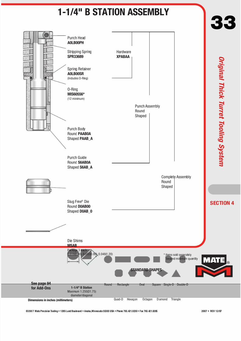
33Punch Head
A0LB00PH
Stripping Spring
SPR33689
Spring Retainer
A0LB00SR(Includes O-Ring)
O-Ring
MIS60556*(12 minimum)
Punch Body
Round PAAB0A
Shaped PAAB_A
Slug Free® Die
Round D0AB00
Shaped D0AB_0
Die Shims
MSABPackage 3 each:
0.016(0.40), 0.032(0.80), 0.048(1.20)
Punch Guide
Round S6AB0A
Shaped S6AB_A
Punch Assembly
Round
Shaped
Complete Assembly
Round
Shaped
* Items sold separately
beyond minimum quantity
1-1/4" B Station
Maximum 1.250(31.75)
diameter/diagonal
SECTION 4
Round Rectangle Oval Square Single-D Double-D
Quad-D TriangleHexagon Octagon Diamond
STANDARD SHAPES
Hardware
XPABAA
1-1/4" B STATION ASSEMBLY
O r i g i n a l T h i c k T u r r e t T o o l i n g S y s t e m
Dimensions in inches (millimeters)
See page 94for Add-Ons
©200 7 Mate Precision Tooling • 1295 Lund Boulevard • Anoka,Minnesota 55303 USA • Phone 763.421.0230 • Fax 763.421.0285 2007 • REV 12/07

7/30/2019 Catalog Ultrafsdfsdf Tec
http://slidepdf.com/reader/full/catalog-ultrafsdfsdf-tec 34/96
34Punch Guide Assembly
AGLC1
Punch Shims
VSACPackage 3 each:
0.016(0.40), 0.032(0.80), 0.048(1.20)
Punch Body
Round PAAC0A
Shaped PAAC_A
Slug Free® Die
Round D0AC00
Shaped D0AC_0
Slitting Insert
Shaped P4AP_A
Slitting Die Body
A0LC00SD
Die Shims
MSACPackage 3 each:
0.016(0.40), 0.032(0.80), 0.048(1.20)
Stripper Plate
Round S6AC0A
Shaped S6AC_A
Punch Retainer
A0LC00PR
Die Inserts
Shaped D0KP_0
D/L = Diagonal/Length
R C = Radius Corners
Slitting Insert withSlug Free Die
2.000(50.80) max. D/L0.709(18.00) max. width
Slug Free Die2.059(52.30) max. D/L
0.768(19.50) max. width
Slitting Insert withDie Inserts
2.000(50.80) max. D/L
0.268(6.80) max. width
Die Inserts, Rectanglesand Ovals
2.028(51.50) max. D/L0.295(7.50) max. width
Maximum
2.000(50.80)
diameter/diagonal
Slitting Tool
Components
ECTION 4
Round Rectangle Oval Square Single-D Double-D
Quad-D TriangleHexagon Octagon Diamond
STANDARD SHAPES
Set Assembly
Round
Shaped
O r i g i n a l T h i c k T u r r e t T o o l i n g S y s t e m
2" C STATION ASSEMBLY
Dimensions in inches (millimeters)
See page 94for Add-Ons
©200 7 Mate Precision Tooling • 1295 Lund Boulevard • Anoka, Minnesota 55303 USA • Phone 763.421.0230 • Fax 763.421.02852007 • REV 12/07

7/30/2019 Catalog Ultrafsdfsdf Tec
http://slidepdf.com/reader/full/catalog-ultrafsdfsdf-tec 35/96
35Punch Guide Assembly
AGLD1
Punch Shims
VSADPackage 3 each:
0.016(0.40), 0.032(0.80), 0.048(1.20)
Punch Body
Round PAAD0A
Shaped PAAD_A
Slug Free® Die
Round D0AD00
Shaped D0AD_0
Slitting Insert
Shaped P4AQ_A
Slitting Die Body
A0LD00SD
Die Shims
MSADPackage 3 each:
0.016(0.40), 0.032(0.80), 0.048(1.20)
Stripper Plate
Round S6AD0A
Shaped S6AD_A
Punch Retainer
A0LD00PR
Die Inserts
Shaped D0KQ_0
Set AssemblyRound
Shaped
Lifter “T” Handle
A0LEH
Slitting Tool
Components
Slitting Insert with
Slug Free Die
3.500(88.90) max.D/L0.709(18.00) max. width
Slug Free Die
3.559(90.40) max.D/L0.768(19.50) max. width
Slitting Insert with Die Inserts3.500(88.90) max.D/L
0.315(8.00) max. width
Die Inserts R C ≤ 0.125(3.18)
3.384(85.95) max. length0.335(8.50) max. width
OR
3.539(89.90) max. length0.175(4.45) max. width
Die Inserts R C > 0.125(3.18)
and Ovals3.520(89.40) max. length
0.335(8.50) max. width
Maximum
3.500(88.90)
diameter/diagonal
D/L = Diagonal/LengthR C = Radius Corners
SECTION 4
Round Rectangle Oval Square Single-D Double-D
Quad-D TriangleHexagon Octagon Diamond
STANDARD SHAPES
3-1/2" D STATION ASSEMBLY
O r i g i n a l T h i c k T u r r e t T o o l i n g S y s t e m
Dimensions in inches (millimeters)
See page 94for Add-Ons
©200 7 Mate Precision Tooling • 1295 Lund Boulevard • Anoka,Minnesota 55303 USA • Phone 763.421.0230 • Fax 763.421.0285 2007 • REV 12/07
7/30/2019 Catalog Ultrafsdfsdf Tec
http://slidepdf.com/reader/full/catalog-ultrafsdfsdf-tec 36/96
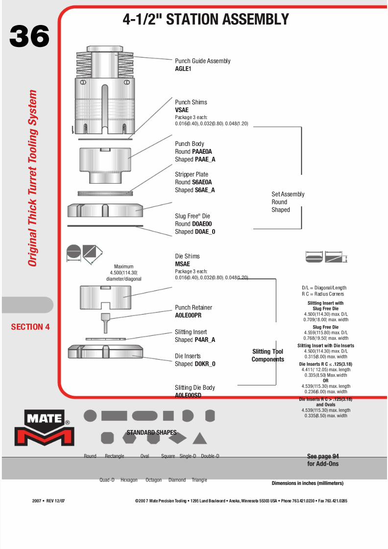
36Punch Guide Assembly
AGLE1
Punch Shims
VSAEPackage 3 each:
0.016(0.40), 0.032(0.80), 0.048(1.20)
Punch Body
Round PAAE0A
Shaped PAAE_A
Slug Free® Die
Round D0AE00
Shaped D0AE_0
Slitting Insert
Shaped P4AR_A
Slitting Die Body
A0LE00SD
Die Shims
MSAEPackage 3 each:
0.016(0.40), 0.032(0.80), 0.048(1.20)
Stripper Plate
Round S6AE0A
Shaped S6AE_A
Punch Retainer
A0LE00PR
Die Inserts
Shaped D0KR_0
Set AssemblyRound
Shaped
D/L = Diagonal/LengthR C = Radius Corners
Slitting Insert withSlug Free Die
4.500(114.30) max. D/L0.709(18.00) max. width
Slug Free Die4.559(115.80) max. D/L
0.768(19.50) max. width
Slitting Insert with Die Inserts4.500(114.30) max. D/L0.315(8.00) max. width
Die Inserts R C ≤ .125(3.18)4.411(112.05) max. length
0.335(8.50) Max.widthOR
4.539(115.30) max. length0.236(6.00) max. width
Die Inserts R C > .125(3.18)and Ovals
4.539(115.30) max. length0.335(8.50) max. width
Maximum
4.500(114.30)
diameter/diagonal
Slitting Tool
Components
ECTION 4
Round Rectangle Oval Square Single-D Double-D
Quad-D TriangleHexagon Octagon Diamond
STANDARD SHAPES
O r i g i n a l T h i c k T u r r e t T o o l i n g S y s t e m
4-1/2" STATION ASSEMBLY
Dimensions in inches (millimeters)
See page 94for Add-Ons
©200 7 Mate Precision Tooling • 1295 Lund Boulevard • Anoka, Minnesota 55303 USA • Phone 763.421.0230 • Fax 763.421.02852007 • REV 12/07
7/30/2019 Catalog Ultrafsdfsdf Tec
http://slidepdf.com/reader/full/catalog-ultrafsdfsdf-tec 37/96
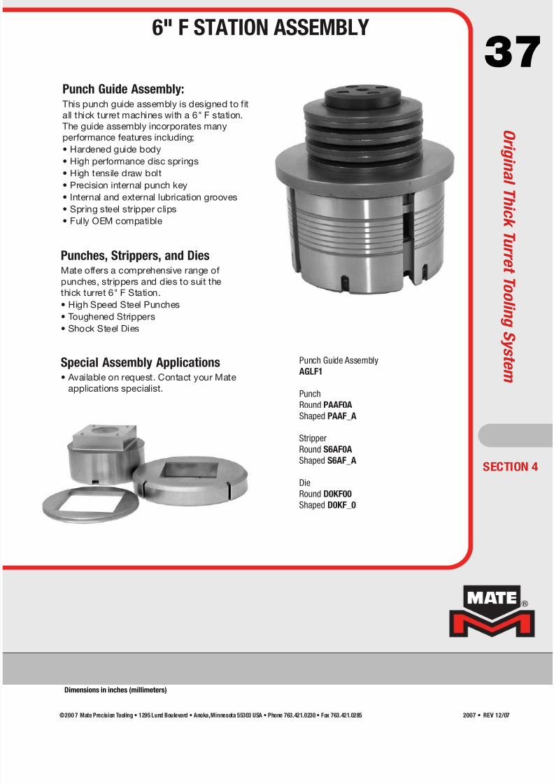
37Punch Guide Assembly:This punch guide assembly is designed to fit
all thick turret machines with a 6" F station.
The guide assembly incorporates many
performance features including;• Hardened guide body
• High performance disc springs
• High tensile draw bolt
• Precision internal punch key
• Internal and external lubrication grooves
• Spring steel stripper clips
• Fully OEM compatible
Punches, Strippers, and Dies
Mate offers a comprehensive range ofpunches, strippers and dies to suit the
thick turret 6" F Station.
• High Speed Steel Punches
• Toughened Strippers
• Shock Steel Dies
Special Assembly Applications• Available on request. Contact your Mate
applications specialist.
SECTION 4
Punch Guide Assembly
AGLF1
Punch
Round PAAF0A
Shaped PAAF_A
Stripper
Round S6AF0A
Shaped S6AF_A
Die
Round D0KF00
Shaped D0KF_0
6" F STATION ASSEMBLY
O r i g i n a l T h i c k T u r r e t T o o l i n g S y s t e m
Dimensions in inches (millimeters)
©200 7 Mate Precision Tooling • 1295 Lund Boulevard • Anoka,Minnesota 55303 USA • Phone 763.421.0230 • Fax 763.421.0285 2007 • REV 12/07

7/30/2019 Catalog Ultrafsdfsdf Tec
http://slidepdf.com/reader/full/catalog-ultrafsdfsdf-tec 38/96
38
Maximum HeavyDuty Punch Size
1.250(31.75)
diameter/diagonal
Maximum Heavy
Duty Die Size
1.309(33.25)
diameter/diagonal
(includes clearance)
Maximum HeavyDuty Punch Size
0.500(12.70)
diameter/diagonal
Maximum Heavy
Duty Die Size
0.559(14.20)
diameter/diagonal
(includes clearance)
®
®
®
Minimum width/diameter in heavy duty is 0.250(6.35)
1/2" A STATION 1-1/4" B STATION
ECTION 5
Features include:
• 1 Degree back taper on punches (per side) • Quick tool change
• Heavy duty Slug Free® diedesign • Premium high speed tool steel punches
• Heavy duty springs (1-1/4" B Station)
• Roof top shear • Quick length adjustment
Canister Assembly
A0VASTCA
Ultra TEC® Heavy Duty
Punch Body
Round PHUA0A
Shaped PHUA_A
Heavy Duty Slug Free® Die
Round DHAA00
Shaped DHAA_0
Die Shims
MSAAPackage 3 each:
0.016(0.40), 0.032(0.80), 0.048(1.20)
Ultra TEC® Guide
Round A0VA0SGU
Shaped A0VA00GU
Ultra TEC® Heavy Duty
Stripper Plate
Round SHKA0A
Shaped SHKA_A
Heavy Duty Canister
Assembly-Metric
A0VBHMCA
Heavy Duty Canister Assembly
A0VBHSCA
Heavy Duty Punch Body
Round PHAB0A
Shaped PHAB_A
Ultra TEC® Heavy Duty
Punch Body
Round PHUB0A
Shaped PHUB_A
Heavy Duty Slug Free® Die
Round DHAB00
Shaped DHAB_0
Die Shims
MSABPackage 3 each:
0.016(0.40), 0.032(0.80), 0.048(1.20)
Ultra TEC® Guide
Round A0VB0SGU
Shaped A0VB00GU
Ultra TEC® Heavy Duty
Stripper Plate
Round SHKB0A
Shaped SHKB_A
U l t r a T E C ® H e a v y D u t y
ULTRA TEC® HEAVY DUTY
Dimensions in inches (millimeters)
See page 94for Add-Ons
©200 7 Mate Precision Tooling • 1295 Lund Boulevard • Anoka, Minnesota 55303 USA • Phone 763.421.0230 • Fax 763.421.02852007 • REV 12/07
7/30/2019 Catalog Ultrafsdfsdf Tec
http://slidepdf.com/reader/full/catalog-ultrafsdfsdf-tec 39/96
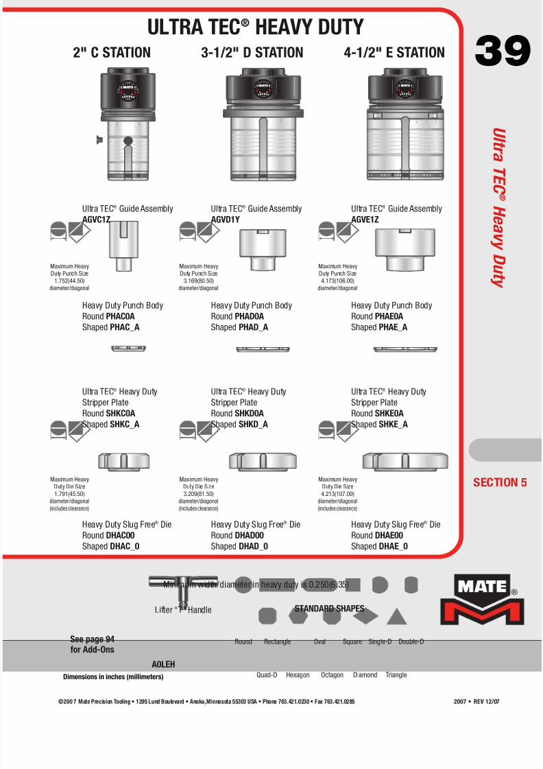
39
Ultra TEC® Guide Assembly
AGVC1Z
Heavy Duty Punch Body
Round PHAC0A
Shaped PHAC_A
Heavy Duty Slug Free® Die
Round DHAC00Shaped DHAC_0
Ultra TEC® Heavy Duty
Stripper PlateRound SHKC0A
Shaped SHKC_A
Ultra TEC® Guide Assembly
AGVD1Y
Heavy Duty Punch Body
Round PHAD0A
Shaped PHAD_A
Heavy Duty Slug Free® Die
Round DHAD00Shaped DHAD_0
Ultra TEC® Heavy Duty
Stripper PlateRound SHKD0A
Shaped SHKD_A
Ultra TEC® Guide Assembly
AGVE1Z
Heavy Duty Punch Body
Round PHAE0A
Shaped PHAE_A
Heavy Duty Slug Free® Die
Round DHAE00Shaped DHAE_0
Ultra TEC® Heavy Duty
Stripper PlateRound SHKE0A
Shaped SHKE_A
Lifter “T” Handle
A0LEH
Minimum width/diameter in heavy duty is 0.250(6.35)
2" C STATION 3-1/2" D STATION 4-1/2" E STATION
®®
®
Maximum HeavyDuty Punch Size
1.752(44.50)
diameter/diagonal
Maximum HeavyDuty Punch Size
3.169(80.50)
diameter/diagonal
Maximum HeavyDuty Punch Size
4.173(106.00)
diameter/diagonal
Maximum Heavy
Duty Die Size
1.791(45.50)
diameter/diagonal
(includes clearance)
Maximum Heavy
Duty Die Size
3.209(81.50)
diameter/diagonal
(includes clearance)
Maximum Heavy
Duty Die Size
4.213(107.00)
diameter/diagonal
(includes clearance)
SECTION 5
Round Rectangle Oval Square Single-D Double-D
Quad-D TriangleHexagon Octagon Diamond
STANDARD SHAPES
ULTRA TEC® HEAVY DUTY
U l t r a T E C ®H e a v y
D u t y
Dimensions in inches (millimeters)
See page 94for Add-Ons
©200 7 Mate Precision Tooling • 1295 Lund Boulevard • Anoka,Minnesota 55303 USA • Phone 763.421.0230 • Fax 763.421.0285 2007 • REV 12/07

7/30/2019 Catalog Ultrafsdfsdf Tec
http://slidepdf.com/reader/full/catalog-ultrafsdfsdf-tec 40/96
40
®
®
Ultra Light 1-1/4" B station canisters apply 60% of the stripping
force of the standard Ultra TEC® 1-1/4" B station canisters.
Ultra Light 1/2" A station canisters apply 70% of the stripping force
of the standard Ultra TEC® 1/2" A station canisters.
®
®
MATE00038 is assembled with 9 medium pressure blue springs. MATE00033 is assembled with 9 medium pressure blue springs.
1/2" A STATION 1-1/4" B STATION
2" C STATION 3-1/2" D AND 4-1/2" E STATION
ECTION 5
Ultra Light Spring
Canister Ultra® Style
MATE00276
(Package of 9)
Heavy Pressure
Gold Springs*
MATE00280
Ultra Light Spring Assembly
MATE00038
Ultra Light Spring
Canister Metric Style
MATE00278
Ultra Light Spring
Canister Ultra® Style
MATE00277
Ultra Light Spring
Canister Metric Style
MATE00279
(Package of 9)
Medium Heavy Pressure
Red Springs*
MATE00281
Ultra Light Spring Assembly
MATE00033
Eliminate Sheet Marking
U l t r a L i g h t ™ T o o l i n g S y s t e m
ULTRA LIGHT™ TOOLING SYSTEMCANISTERS AND SPRING PACKS
*See page 41 for details on spring selection.
©200 7 Mate Precision Tooling • 1295 Lund Boulevard • Anoka, Minnesota 55303 USA • Phone 763.421.0230 • Fax 763.421.02852007 • REV 12/07

7/30/2019 Catalog Ultrafsdfsdf Tec
http://slidepdf.com/reader/full/catalog-ultrafsdfsdf-tec 41/96
41Mate Ultra Light™ spring packs provide precise control
of the stripping pressure when using any thick turret
guide assembly manufactured by Mate. Benefits include:
• Reduced spring pressure to eliminate unwanted sheet
marking. Designed for thin or decorative materials.• Ideal for high polish, textured, pre-painted or reflective
metals where finish appearance is critical.
• Quieter punching in all applications. Noise levels
reduced by as much as 10 decibels.
• Maximum control over total spring pressure.
Combine two sets of springs for nine pressure
variations. See table.
Mate punch guide assemblies complete with Mate Ultra
Light™ spring packs are now available for popular thick
turret tooling styles including:
• Mate Ultra TEC®
• Mate Ultra TEC® fully guided
• Mate Ultra XT™
• Original style thick turret
Mate Ultra TEC® 2" C MATE00487
3-1/2" D MATE00488
4-1/2" E MATE00489
Mate Ultra TEC® 2" C MATE00490
fully guided 3-1/2" D MATE00491
4-1/2" E MATE00492
Mate Ultra XT™ 2" C MATE00496
3-1/2" D MATE00497
4-1/2" E MATE00498
Original style thick turret 2" C MATE00493
3-1/2" D MATE00494
4-1/2" E MATE00495
Additional springs for 2" C MATE00280
heavier application. 3-1/2" D MATE00281
(pack of 9) 4-1/2" E MATE00281
Note: Your existing Mate thick
turret guides can be retrofitted with
Mate Ultra Light™ spring packs.
TOOL STYLE STATION PART NUMBER
3 blue 4% 3 blue 5%
6 blue 7% 6 blue 10%
9 blue 10% 3 red 11%
3 gold 12% 9 blue 15%
3 blue + 3 gold 15% 3 blue + 3 red 16%
6 blue + 3 gold 19% 6 blue + 3 red 21%
6 gold 25% 6 red 22%
3 blue + 6 gold 27% 3 blue + 6 red 27%
9 gold 36% 9 red 33%
2" C Station3-1/2" D Station
4-1/2" E Station
SECTION 5
Mate Ultra Light™ spring packs are supplied
with 9 blue springs. The spring pressure can be
altered by removing and/or replacing the springs.
Additional red and gold springs are available.
(See page 42)
Use the table below to select the springcombination to achieve the desired stripping
pressure. The spring pressure is stated as the
percentage achieved in the Ultra Light guide as
compared to an Ultra TEC disc spring stack.
Eliminate Sheet Marking
THICK TURRET PUNCH GUIDE ASSEMBLIES
WITH ULTRA LIGHT™ SPRING PACKS
U l t r a L i g h t ™T o o
l i n g S y s t e m
©200 7 Mate Precision Tooling • 1295 Lund Boulevard • Anoka,Minnesota 55303 USA • Phone 763.421.0230 • Fax 763.421.0285 2007 • REV 12/07
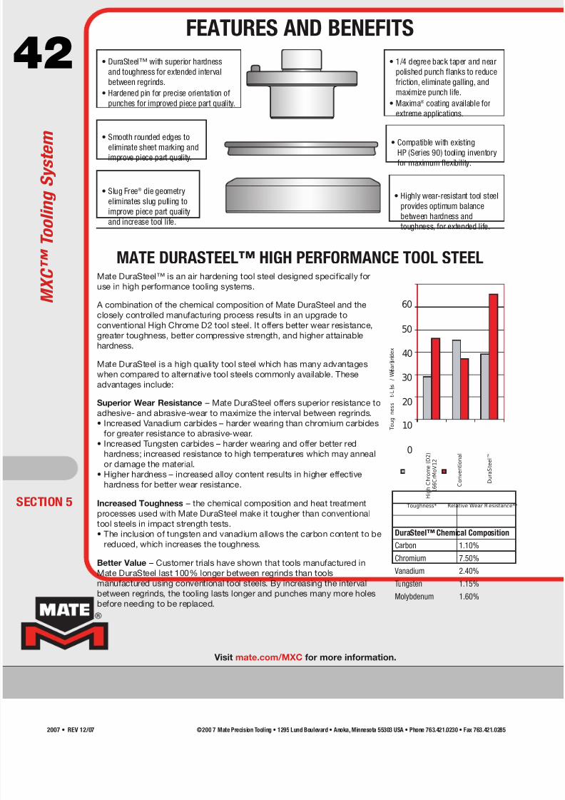
7/30/2019 Catalog Ultrafsdfsdf Tec
http://slidepdf.com/reader/full/catalog-ultrafsdfsdf-tec 42/96
42 • DuraSteel™ with superior hardness
and toughness for extended interval
between regrinds.
• Hardened pin for precise orientation of
punches for improved piece part quality.
• Smooth rounded edges toeliminate sheet marking and
improve piece part quality.
• Slug Free® die geometry
eliminates slug pulling to
improve piece part quality
and increase tool life.
• 1/4 degree back taper and near
polished punch flanks to reduce
friction, eliminate galling, and
maximize punch life.
• Maxima® coating available for
extreme applications.
• Compatible with existingHP (Series 90) tooling inventory
for maximum flexibility.
• Highly wear-resistant tool steel
provides optimum balance
between hardness and
toughness, for extended life.
MATE DURASTEEL™ HIGH PERFORMANCE TOOL STEEL
Mate DuraSteel™ is an air hardening tool steel designed specifically foruse in high performance tooling systems.
A combination of the chemical composition of Mate DuraSteel and the
closely controlled manufacturing process results in an upgrade to
conventional High Chrome D2 tool steel. It offers better wear resistance,
greater toughness, better compressive strength, and higher attainable
hardness.
Mate DuraSteel is a high quality tool steel which has many advantages
when compared to alternative tool steels commonly available. These
advantages include:
Superior Wear Resistance – Mate DuraSteel offers superior resistance to
adhesive- and abrasive-wear to maximize the interval between regrinds.
• Increased Vanadium carbides – harder wearing than chromium carbidesfor greater resistance to abrasive-wear.
• Increased Tungsten carbides – harder wearing and offer better red
hardness; increased resistance to high temperatures which may anneal
or damage the material.
• Higher hardness – increased alloy content results in higher effective
hardness for better wear resistance.
Increased Toughness – the chemical composition and heat treatment
processes used with Mate DuraSteel make it tougher than conventional
tool steels in impact strength tests.
• The inclusion of tungsten and vanadium allows the carbon content to be
reduced, which increases the toughness.
Better Value – Customer trials have shown that tools manufactured inMate DuraSteel last 100% longer between regrinds than tools
manufactured using conventional tool steels. By increasing the interval
between regrinds, the tooling lasts longer and punches many more holes
before needing to be replaced.
Toughness* Relative Wear R esistance**
50
40
30
20
10
0
H i g h C h r o m e ( D 2 )
1 6 6 C r M o V 1 2
C o n v e n t i o n a l
D u r a S t e e l ™
T o u g
n e s s
t - L
s
/ W e a r I n d e x
60
DuraSteel™ Chemical Composition
Carbon 1.10%
Chromium 7.50% Vanadium 2.40%
Tungsten 1.15%
Molybdenum 1.60%
ECTION 5
M X C ™ T o o l i n g S y s t e m
FEATURES AND BENEFITS
Visit mate.com/MXC for more information.
©200 7 Mate Precision Tooling • 1295 Lund Boulevard • Anoka, Minnesota 55303 USA • Phone 763.421.0230 • Fax 763.421.02852007 • REV 12/07
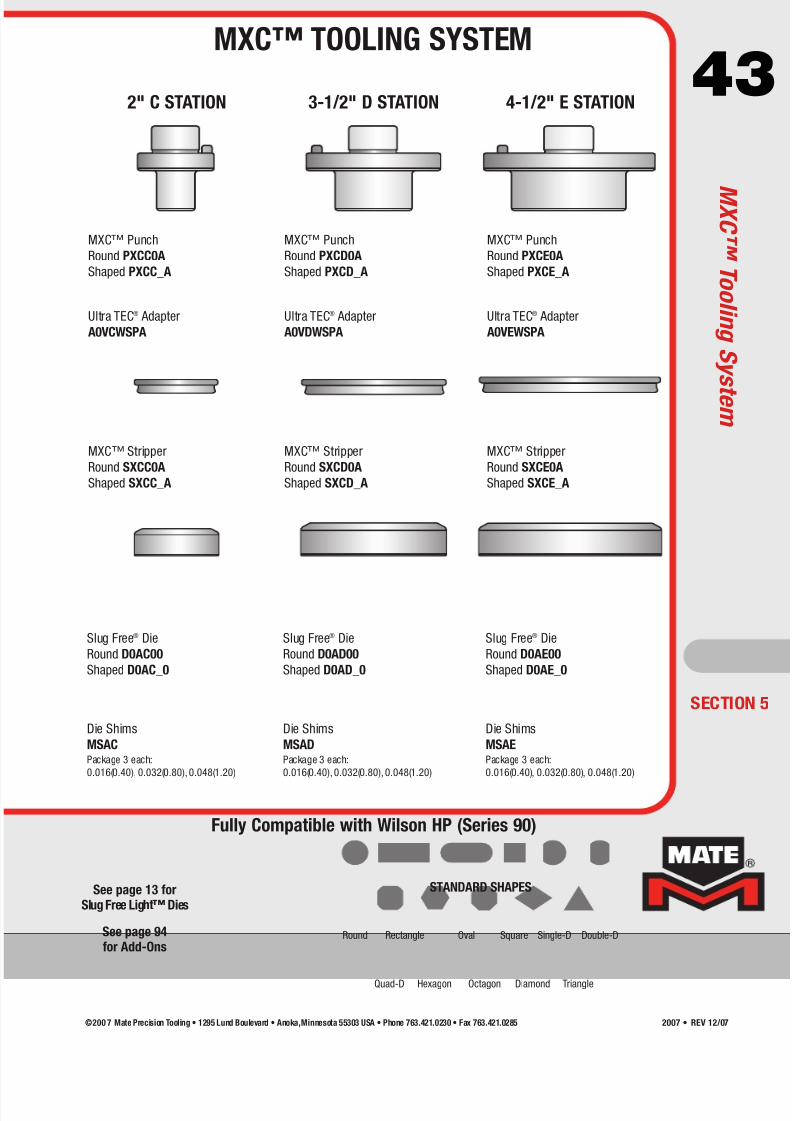
7/30/2019 Catalog Ultrafsdfsdf Tec
http://slidepdf.com/reader/full/catalog-ultrafsdfsdf-tec 43/96
432" C STATION 3-1/2" D STATION 4-1/2" E STATION
SECTION 5
Round Rectangle Oval Square Single-D Double-D
Quad-D TriangleHexagon Octagon Diamond
STANDARD SHAPESSee page 13 forSlug Free Light™ Dies
Ultra TEC® Adapter
A0VCWSPA
MXC™ Punch
Round PXCC0A
Shaped PXCC_A
Slug Free® Die
Round D0AC00
Shaped D0AC_0
Die Shims
MSACPackage 3 each:
0.016(0.40), 0.032(0.80), 0.048(1.20)
MXC™ Stripper
Round SXCC0A
Shaped SXCC_A
Ultra TEC® Adapter
A0VDWSPA
MXC™ Punch
Round PXCD0A
Shaped PXCD_A
Slug Free® Die
Round D0AD00
Shaped D0AD_0
Die Shims
MSADPackage 3 each:
0.016(0.40), 0.032(0.80), 0.048(1.20)
MXC™ Stripper
Round SXCD0A
Shaped SXCD_A
Ultra TEC® Adapter
A0VEWSPA
MXC™ Punch
Round PXCE0A
Shaped PXCE_A
Slug Free® Die
Round D0AE00
Shaped D0AE_0
Die Shims
MSAEPackage 3 each:
0.016(0.40), 0.032(0.80), 0.048(1.20)
MXC™ Stripper
Round SXCE0A
Shaped SXCE_A
Fully Compatible with Wilson HP (Series 90)
MXC™ TOOLING SYSTEM
MX C ™T o o l i n g S y s t e m
See page 94for Add-Ons
©200 7 Mate Precision Tooling • 1295 Lund Boulevard • Anoka,Minnesota 55303 USA • Phone 763.421.0230 • Fax 763.421.0285 2007 • REV 12/07
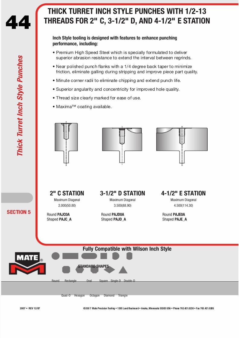
7/30/2019 Catalog Ultrafsdfsdf Tec
http://slidepdf.com/reader/full/catalog-ultrafsdfsdf-tec 44/96
44
ECTION 5
2" C STATIONMaximum Diagonal
2.000(50.80)
3-1/2" D STATIONMaximum Diagonal
3.500(88.90)
4-1/2" E STATIONMaximum Diagonal
4.500(114.30)
Inch Style tooling is designed with features to enhance punching
performance, including:
• Premium High Speed Steel which is specially formulated to deliver
superior abrasion resistance to extend the interval between regrinds.
• Near polished punch flanks with a 1/4 degree back taper to minimize
friction, eliminate galling during stripping and improve piece part quality.
• Minute corner radii to eliminate chipping and extend punch life.
• Superior angularity and concentricity for improved hole quality.
• Thread size clearly marked for ease of use.
• Maxima™ coating available.
Round PAJD0A
Shaped PAJD_A
Round PAJE0A
Shaped PAJE_A
Fully Compatible with Wilson Inch Style
Round Rectangle Oval Square Single-D Double-D
Quad-D TriangleHexagon Octagon Diamond
STANDARD SHAPES
T h i c k T u r r e t I n c h S t y l e P u n c h e s
THICK TURRET INCH STYLE PUNCHES WITH 1/2-13
THREADS FOR 2" C, 3-1/2" D, AND 4-1/2" E STATION
Round PAJC0A
Shaped PAJC_A
©200 7 Mate Precision Tooling • 1295 Lund Boulevard • Anoka, Minnesota 55303 USA • Phone 763.421.0230 • Fax 763.421.02852007 • REV 12/07
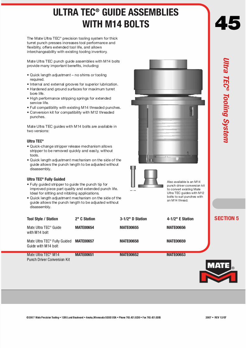
7/30/2019 Catalog Ultrafsdfsdf Tec
http://slidepdf.com/reader/full/catalog-ultrafsdfsdf-tec 45/96
45
Also available is an M14punch driver conversion kit
to convert existing Mate
Ultra TEC guides with M12
bolts to suit punches with
an M14 thread.
Tool Style / Station 2" C Station 3-1/2" D Station 4-1/2" E Station
Mate Ultra TEC® Guide MATE00654 MATE00655 MATE00656
with M14 bolt
Mate Ultra TEC® Fully Guided MATE00657 MATE00658 MATE00659
Guide with M14 bolt
Mate Ultra TEC® M14 MATE00651 MATE00652 MATE00653
Punch Driver Conversion Kit
The Mate Ultra TEC® precision tooling system for thick
turret punch presses increases tool performance and
flexiblity, offers extended tool life, and allows
interchangeability with existing tooling inventory.
Mate Ultra TEC punch guide assemblies with M14 boltsprovide many important benefits, including:
• Quick length adjustment – no shims or tooling
required.
• Internal and external grooves for superior lubrication.
• Hardened and ground surfaces for maximum turret
bore life.
• High performance stripping springs for extended
service life.
• Full compatibility with existing M14 threaded punches.
• Conversion kit for compatibility with M12 threaded
punches.
Mate Ultra TEC guides with M14 bolts are available in
two versions:
Ultra TEC®
• Quick-change stripper release mechanism allows
stripper to be removed quickly and easily, without
tools.
• Quick length adjustment mechanism on the side of the
guide allows the punch length to be adjusted without
disassembly.
Ultra TEC® Fully Guided
• Fully guided stripper to guide the punch tip forimproved piece part quality and extended punch life.
Ideal for slitting and nibbling applications.
• Quick length adjustment mechanism on the side of the
guide allows the punch length to be adjusted without
disassembly.
SECTION 5
ULTRA TEC® GUIDE ASSEMBLIES
WITH M14 BOLTS
U l t r a T E C ®T o o l i n g S y s t e m
©200 7 Mate Precision Tooling • 1295 Lund Boulevard • Anoka,Minnesota 55303 USA • Phone 763.421.0230 • Fax 763.421.0285 2007 • REV 12/07
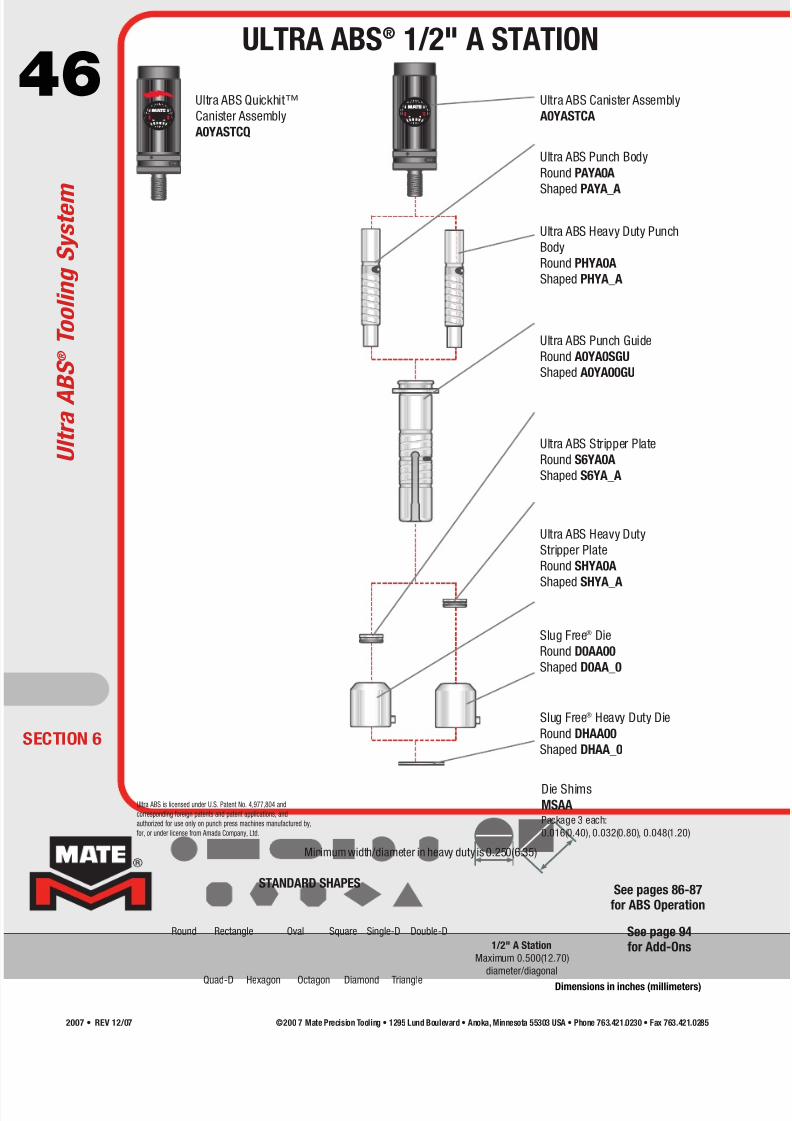
7/30/2019 Catalog Ultrafsdfsdf Tec
http://slidepdf.com/reader/full/catalog-ultrafsdfsdf-tec 46/96
46®
®
Ultra ABS is licensed under U.S. Patent No. 4,977,804 and
corresponding foreign patents and patent applications, and
authorized for use only on punch press machines manufactured by,
for, or under license from Amada Company, Ltd.
Minimum width/diameter in heavy duty is 0.250(6.35)
1/2" A Station
Maximum 0.500(12.70)
diameter/diagonal
ECTION 6
Round Rectangle Oval Square Single-D Double-D
Quad-D TriangleHexagon Octagon Diamond
STANDARD SHAPES
Ultra ABS Quickhit™
Canister Assembly
A0YASTCQ
Ultra ABS Punch Body
Round PAYA0A
Shaped PAYA_A
Ultra ABS Heavy Duty Punch
Body
Round PHYA0A
Shaped PHYA_A
Ultra ABS Punch Guide
Round A0YA0SGU
Shaped A0YA00GU
Ultra ABS Stripper Plate
Round S6YA0A
Shaped S6YA_A
Ultra ABS Heavy Duty
Stripper Plate
Round SHYA0A
Shaped SHYA_A
Slug Free® Heavy Duty Die
Round DHAA00
Shaped DHAA_0
Slug Free® Die
Round D0AA00
Shaped D0AA_0
Die ShimsMSAAPackage 3 each:
0.016(0.40), 0.032(0.80), 0.048(1.20)
Ultra ABS Canister Assembly
A0YASTCA
U l t r a A B S ® T o o l i n g S y s t e m
ULTRA ABS® 1/2" A STATION
Dimensions in inches (millimeters)
See page 94for Add-Ons
See pages 86-87for ABS Operation
©200 7 Mate Precision Tooling • 1295 Lund Boulevard • Anoka, Minnesota 55303 USA • Phone 763.421.0230 • Fax 763.421.02852007 • REV 12/07

7/30/2019 Catalog Ultrafsdfsdf Tec
http://slidepdf.com/reader/full/catalog-ultrafsdfsdf-tec 47/96
47®
®
®
®
A clip tool (MIS59723) is
included in the purchase of an
Ultra ABS fully guided punch
guide (A0YB00GG).
Minimum width/diameter in heavy duty is 0.250(6.35)
1-1/4" B Station
Maximum 1.250(31.75)
diameter/diagonal
SECTION 6
Round Rectangle Oval Square Single-D Double-D
Quad-D TriangleHexagon Octagon Diamond
STANDARD SHAPES
Ultra ABS Quickhit™
Canister Assembly
A0YBSTCQ
Heavy Duty
Canister Assembly
A0YBHSCARecommended when
material thickness
exceeds 0.118(3.00)
Ultra ABS Fully Guided
Punch Guide
A0YB00GG
Ultra ABS Fully Guided
Stripper Plate
Round S6YK0A
Shaped S6YK_A
Ultra ABS Heavy Duty
Canister Assembly
A0YBHSCA
Ultra ABS Heavy Duty Punch
Body
Round PHYB0A
Shaped PHYB_A
Ultra ABS Punch Guide
Round A0YB0SGU
Shaped A0YB00GU
Ultra ABS Stripper Plate
Round S6YB0A
Shaped S6YB_A
Ultra ABS Heavy Duty
Stripper Plate
Round SHYB0AShaped SHYB_A
Slug Free® Heavy Duty Die
Round DHAB00
Shaped DHAB_0
Slug Free® Die
Round D0AB00
Shaped D0AB_0
Die ShimsMSABPackage 3 each:
0.016(0.40), 0.032(0.80), 0.048(1.20)
Ultra ABS Canister Assembly
A0YBSTCA
Clip ToolMIS59723
Ultra ABS Punch Body
Round PAYB0A
Shaped PAYB_A
ULTRA ABS® 1-1/4" B STATION
U l t r a A B S ®T o o l i n
g S y s t e m
Dimensions in inches (millimeters)
See page 94for Add-Ons
See pages 86-87for ABS Operation
©200 7 Mate Precision Tooling • 1295 Lund Boulevard • Anoka,Minnesota 55303 USA • Phone 763.421.0230 • Fax 763.421.0285 2007 • REV 12/07

7/30/2019 Catalog Ultrafsdfsdf Tec
http://slidepdf.com/reader/full/catalog-ultrafsdfsdf-tec 48/96
48
®®
Maximum
2.000(50.80)
diameter/diagonal
Maximum
3.500(88.90)
diameter/diagonal
Maximum
4.500(114.30)
diameter/diagonal
2" C STATION 3-1/2" D STATION 4-1/2" E STATION
ECTION 6
Round Rectangle Oval Square Single-D Double-D
Quad-D TriangleHexagon Octagon Diamond
STANDARD SHAPES
Ultra ABS Guide Assembly
AGYC1Z
Original Style Punch Body
Round PAAC0A
Shaped PAAC_A
Ultra ABS Stripper PlateRound S6YC0A
Shaped S6YC_A
Slug Free® Die
Round D0AC00
Shaped D0AC_0
Die Shims
MSACPackage 3 each:
0.016(0.40), 0.032(0.80), 0.048(1.20)
Ultra ABS Guide Assembly
AGYD1Y
Original Style Punch Body
Round PAAD0A
Shaped PAAD_A
Ultra ABS Stripper PlateRound S6YD0A
Shaped S6YD_A
Slug Free® Die
Round D0AD00
Shaped D0AD_0
Die Shims
MSADPackage 3 each:
0.016(0.40), 0.032(0.80), 0.048(1.20)
Ultra ABS Guide Assembly
AGYE1Z
Original Style Punch Body
Round PAAE0A
Shaped PAAE_A
Ultra ABS Stripper PlateRound S6YE0A
Shaped S6YE_A
Slug Free® Die
Round D0AE00
Shaped D0AE_0
Die Shims
MSAEPackage 3 each:
0.016(0.40), 0.032(0.80), 0.048(1.20)
®
U l t r a A B S ® T o o l i n g S y s t e m
ULTRA ABS® GUIDE ASSEMBLIESFOR THICK TURRET STYLE PUNCHES
Dimensions in inches (millimeters)
See page 94for Add-Ons
See pages 86-87for ABS Operation
©200 7 Mate Precision Tooling • 1295 Lund Boulevard • Anoka, Minnesota 55303 USA • Phone 763.421.0230 • Fax 763.421.02852007 • REV 12/07
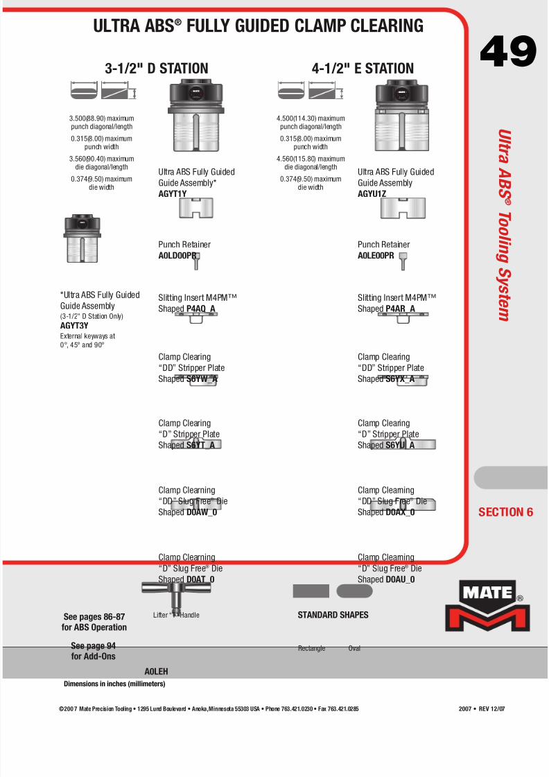
7/30/2019 Catalog Ultrafsdfsdf Tec
http://slidepdf.com/reader/full/catalog-ultrafsdfsdf-tec 49/96
49
Lifter “T” Handle
®
A0LEH
®®
4.500(114.30) maximumpunch diagonal/length
0.315(8.00) maximumpunch width
4.560(115.80) maximumdie diagonal/length
0.374(9.50) maximumdie width
3.500(88.90) maximumpunch diagonal/length
0.315(8.00) maximumpunch width
3.560(90.40) maximumdie diagonal/length
0.374(9.50) maximumdie width
3-1/2" D STATION 4-1/2" E STATION
SECTION 6
Rectangle Oval
STANDARD SHAPES
Ultra ABS Fully Guided
Guide Assembly*
AGYT1Y
Punch Retainer
A0LD00PR
Clamp Clearing
“DD” Stripper Plate
Shaped S6YW_A
Clamp Clearing
“D” Stripper Plate
Shaped S6YT_A
Clamp Clearning
“DD” Slug Free® Die
Shaped D0AW_0
Clamp Clearning
“D” Slug Free® Die
Shaped D0AT_0
*Ultra ABS Fully Guided
Guide Assembly(3-1/2" D Station Only)
AGYT3YExternal keyways at
0°, 45° and 90°
Slitting Insert M4PM™
Shaped P4AQ_A
Ultra ABS Fully Guided
Guide Assembly
AGYU1Z
Punch Retainer
A0LE00PR
Clamp Clearing
“DD” Stripper Plate
Shaped S6YX_A
Clamp Clearing
“D” Stripper Plate
Shaped S6YU_A
Clamp Clearning
“DD” Slug Free® Die
Shaped D0AX_0
Clamp Clearning
“D” Slug Free® Die
Shaped D0AU_0
Slitting Insert M4PM™
Shaped P4AR_A
ULTRA ABS® FULLY GUIDED CLAMP CLEARING
U l t r a A B S ®T o o l i n
g S y s t e m
Dimensions in inches (millimeters)
See page 94for Add-Ons
See pages 86-87for ABS Operation
©200 7 Mate Precision Tooling • 1295 Lund Boulevard • Anoka,Minnesota 55303 USA • Phone 763.421.0230 • Fax 763.421.0285 2007 • REV 12/07
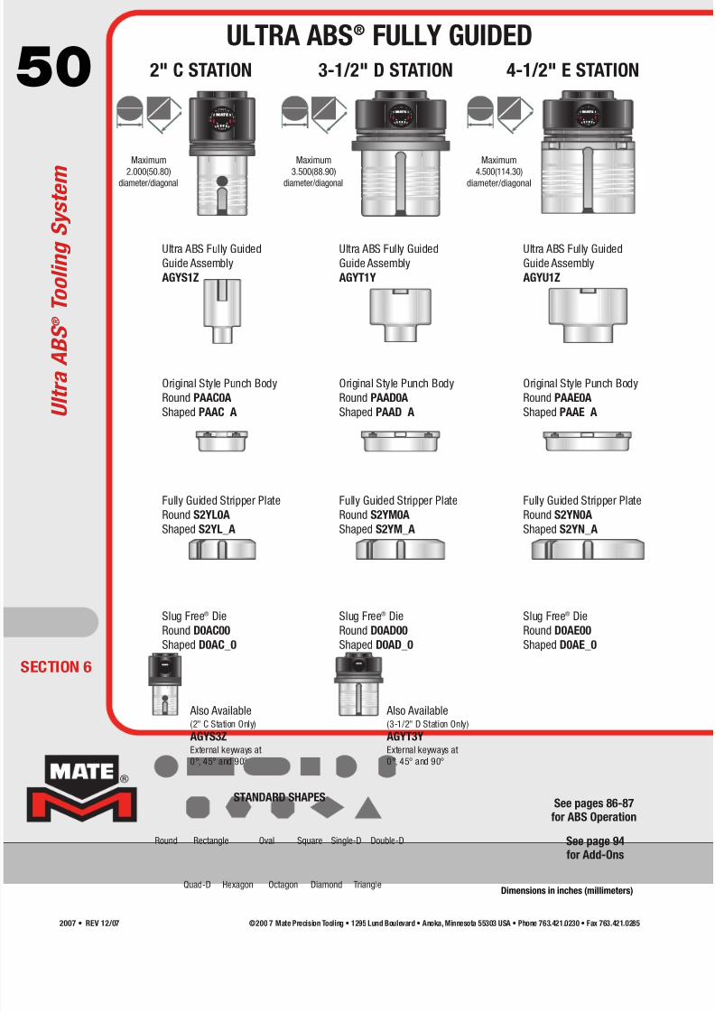
7/30/2019 Catalog Ultrafsdfsdf Tec
http://slidepdf.com/reader/full/catalog-ultrafsdfsdf-tec 50/96
50®®
®
®
®
Maximum
2.000(50.80)
diameter/diagonal
Maximum
3.500(88.90)
diameter/diagonal
Maximum
4.500(114.30)
diameter/diagonal
2" C STATION 3-1/2" D STATION 4-1/2" E STATION
ECTION 6
Round Rectangle Oval Square Single-D Double-D
Quad-D TriangleHexagon Octagon Diamond
STANDARD SHAPES
Ultra ABS Fully Guided
Guide Assembly
AGYS1Z
Fully Guided Stripper Plate
Round S2YL0A
Shaped S2YL_A
Slug Free® Die
Round D0AC00
Shaped D0AC_0
Also Available(2" C Station Only)
AGYS3ZExternal keyways at
0°, 45° and 90°
Original Style Punch Body
Round PAAC0A
Shaped PAAC_A
Also Available(3-1/2" D Station Only)
AGYT3YExternal keyways at
0°, 45° and 90°
Ultra ABS Fully Guided
Guide Assembly
AGYT1Y
Fully Guided Stripper Plate
Round S2YM0A
Shaped S2YM_A
Slug Free® Die
Round D0AD00
Shaped D0AD_0
Original Style Punch Body
Round PAAD0A
Shaped PAAD_A
Ultra ABS Fully Guided
Guide Assembly
AGYU1Z
Fully Guided Stripper Plate
Round S2YN0A
Shaped S2YN_A
Slug Free® Die
Round D0AE00
Shaped D0AE_0
Original Style Punch Body
Round PAAE0A
Shaped PAAE_A U l t r a A B S ® T o o l i n g S y s t e m
ULTRA ABS® FULLY GUIDED
Dimensions in inches (millimeters)
See page 94for Add-Ons
See pages 86-87for ABS Operation
©200 7 Mate Precision Tooling • 1295 Lund Boulevard • Anoka, Minnesota 55303 USA • Phone 763.421.0230 • Fax 763.421.02852007 • REV 12/07

7/30/2019 Catalog Ultrafsdfsdf Tec
http://slidepdf.com/reader/full/catalog-ultrafsdfsdf-tec 51/96
51®®
Maximum HeavyDuty Punch Size
1.752(44.50)
diameter/diagonal
Maximum HeavyDuty Punch Size
3.169(80.50)
diameter/diagonal
Maximum HeavyDuty Punch Size
4.173(106.00)
diameter/diagonal
Maximum Heavy
Duty Die Size
1.791(45.50)
diameter/diagonal
(includes clearance)
Maximum Heavy
Duty Die Size
3.209(81.50)
diameter/diagonal
(includes clearance)
Maximum Heavy
Duty Die Size
4.213(107.00)
diameter/diagonal
(includes clearance)
Lifter “T” Handle
A0LEH
Minimum width/diameter in heavy duty is 0.250(6.35)
2" C STATION 3-1/2" D STATION 4-1/2" E STATION
SECTION 6
Round Rectangle Oval Square Single-D Double-D
Quad-D TriangleHexagon Octagon Diamond
STANDARD SHAPES
Ultra ABS Guide Assembly
AGYC1Z
Ultra ABS Heavy Duty Stripper
Plate
Round SHYC0AShaped SHYC_A
Heavy Duty Slug Free® Die
Round DHAC00
Shaped DHAC_0
Heavy Duty Punch Body
Round PHAC0A
Shaped PHAC_A
Ultra ABS Guide Assembly
AGYD1Y
Ultra ABS Heavy Duty
Stripper Plate
Round SHYD0AShaped SHYD_A
Heavy Duty Slug Free® Die
Round DHAD00
Shaped DHAD_0
Heavy Duty Punch Body
Round PHAD0A
Shaped PHAD_A
Ultra ABS Guide Assembly
AGYE1Z
Ultra ABS Heavy Duty
Stripper Plate
Round SHYE0AShaped SHYE_A
Heavy Duty Slug Free® Die
Round DHAE00
Shaped DHAE_0
Heavy Duty Punch Body
Round PHAE0A
Shaped PHAE_A
®
ULTRA ABS® HEAVY DUTY
U l t r a A B S ®T o o l i n
g S y s t e m
Dimensions in inches (millimeters)
See page 94for Add-Ons
See pages 86-87for ABS Operation
©200 7 Mate Precision Tooling • 1295 Lund Boulevard • Anoka,Minnesota 55303 USA • Phone 763.421.0230 • Fax 763.421.0285 2007 • REV 12/07
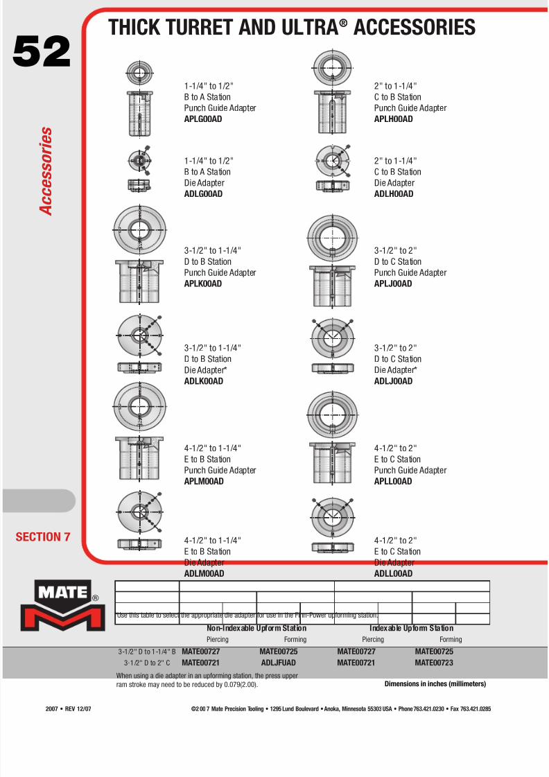
7/30/2019 Catalog Ultrafsdfsdf Tec
http://slidepdf.com/reader/full/catalog-ultrafsdfsdf-tec 52/96
52
A c c e s s o r i e s
THICK TURRET AND ULTRA® ACCESSORIES
Dimensions in inches (millimeters)
1-1/4" to 1/2"
B to A Station
Punch Guide Adapter
APLG00AD
3-1/2" to 1-1/4"
D to B Station
Punch Guide AdapterAPLK00AD
3-1/2" to 1-1/4"
D to B Station
Die Adapter*
ADLK00AD
1-1/4" to 1/2"
B to A Station
Die Adapter
ADLG00AD
4-1/2" to 1-1/4"
E to B Station
Punch Guide Adapter
APLM00AD
4-1/2" to 1-1/4"E to B Station
Die Adapter
ADLM00AD
2" to 1-1/4"
C to B Station
Punch Guide Adapter
APLH00AD
3-1/2" to 2"
D to C Station
Punch Guide AdapterAPLJ00AD
3-1/2" to 2"
D to C Station
Die Adapter*
ADLJ00AD
2" to 1-1/4"
C to B Station
Die Adapter
ADLH00AD
4-1/2" to 2"
E to C Station
Punch Guide Adapter
APLL00AD
4-1/2" to 2"E to C Station
Die Adapter
ADLL00AD
Non-Indexable Upform Station Indexable Upform Station
Piercing Forming Piercing Forming
3-1/2" D to 1-1/4" B MATE00727 MATE00725 MATE00727 MATE00725
3-1/2" D to 2" C MATE00721 ADLJFUAD MATE00721 MATE00723
ECTION 7
*Use this table to select the appropriate die adapter for use in the Finn-Power upforming station.
When using a die adapter in an upforming station, the press upper
ram stroke may need to be reduced by 0.079(2.00).
©2 00 7 Mate Precision Tooling • 1295 Lund Boulevard • Anoka, Minnesota 55303 USA • Phone 763.421.0230 • Fax 763.421.02852007 • REV 12/07

7/30/2019 Catalog Ultrafsdfsdf Tec
http://slidepdf.com/reader/full/catalog-ultrafsdfsdf-tec 53/96
53THICK TURRET AND ULTRA® ACCESSORIES
Dimensions in inches (millimeters)
1/2" A Station
Original Style Round Punch
Anti-Rotation Clamp
1-1/4" B Station
Original Style Round Punch
Anti-Rotation Clamp
1-1/4" B Station HP (Series 90)
Style Round Punch
Anti-Rotation Clip
1-1/4" B Station Punch
Length Adjustment Clamp
HP (Series 90) Driver Assembly
Roller Die for Ultraform
System Special Assemblies
(1-1/4" B Station Only)
Pin for Original Style Round Punch
when used with Ultra Guide
1/2" A and 1-1/4" B Station (12 minimum)
Brush Die for Ultraform
System Special Assemblies
(B thru E Stations)
Replacement Brush
Assembly for
Brush Dies (3 minimum)
Clip Tool for Ultra 1-1/4" B Station
Fully Guided Punch Guide
Stripper Clip
A0LEH
* Items sold separately beyond
minimum quantity
ULTRA® SYSTEM ANTI-ROTATION CLAMPS FOR ROUND PUNCHES
SOFT FACE STRIPPER PADS - ADHESIVE BACKED URETHANE
MORE ACCESSORIES FOR ULTRA® AND ULTRAFORM®
A0VAASAC A0VBASAC A0VBWSAC A0VBWGAC
Soft faced stripper pads for thick turret and Ultra
style tooling - 0.009(0.25) thick adhesive backedurethane to prevent material scratching and reduce
noise levels.
A Station Soft Face Stripper Pad - Package 6
B Station Soft Face Stripper Pad - Package 6
C Station Soft Face Stripper Pad - Package 6
D Station Soft Face Stripper Pad - Package 4
E Station Soft Face Stripper Pad - Package 4
3 mm Urethane Slug Ejectors
6 mm Urethane Slug Ejectors
URE40002*MIS60256*
MIS61188*
URE40010*
A0LB00FG
MIS59723
A0LA00SF
A0LB00SF
A0LC00SF
A0LD00SF
A0LE00SF
B StationC Station
D Station
E Station
ADLB0001ADLC0001
ADLD0001
ADLE0001
0.157(4.00) Diameter Pin (12 Minimum)
Lifter “T” Handle
SECTION 7
Urethane Slug Ejectors
3 and 6 mm Diameters
(12 minimum)
Medium India Oil Stone
STO29807
A c c e s s o r i e s
©2 00 7 Mate Precision Tooling • 1295 Lund Boulevard • Anoka, Minnesota 55303 USA • Phone 763.421.0230 • Fax 763.421.0285 2007 • REV 12/07
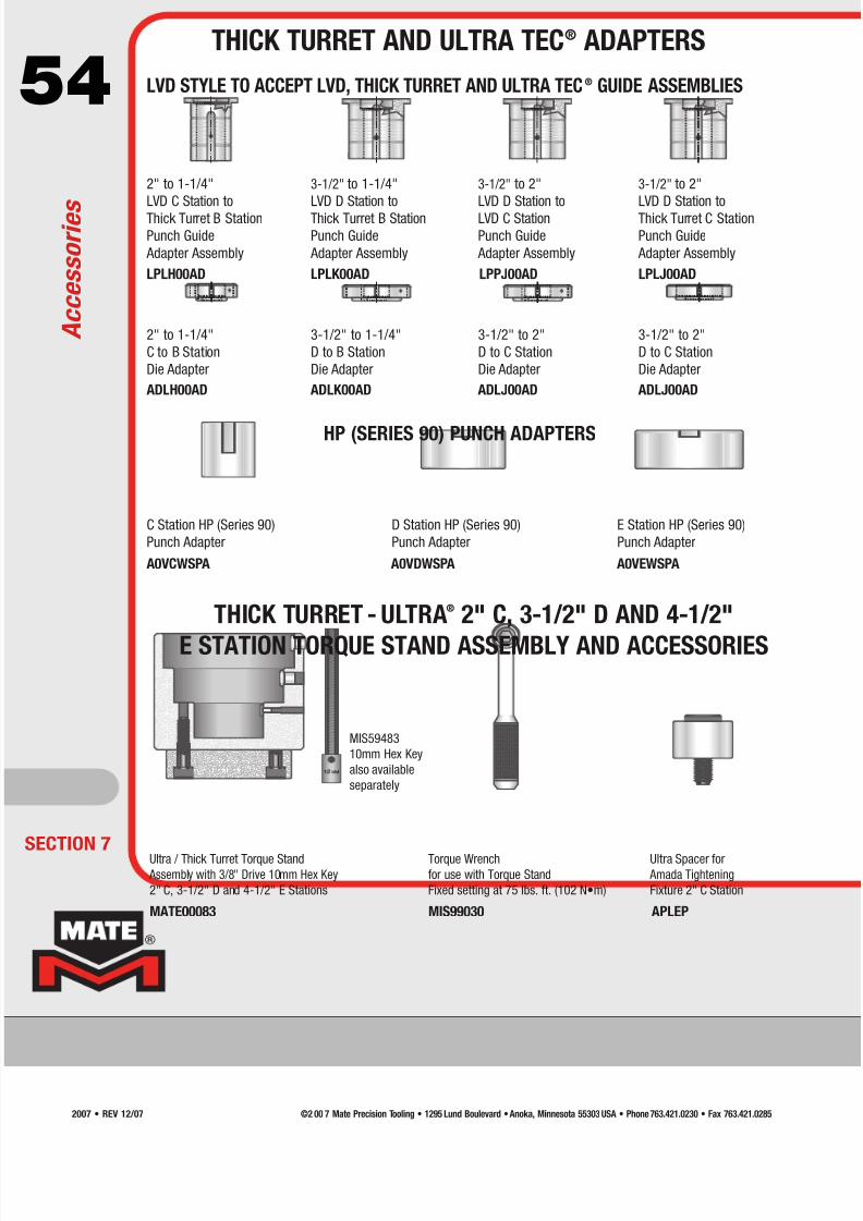
7/30/2019 Catalog Ultrafsdfsdf Tec
http://slidepdf.com/reader/full/catalog-ultrafsdfsdf-tec 54/96
54 LVD STYLE TO ACCEPT LVD, THICK TURRET AND ULTRA TEC® GUIDE ASSEMBLIES
HP (SERIES 90) PUNCH ADAPTERS
2" to 1-1/4"
LVD C Station to
Thick Turret B StationPunch Guide
Adapter Assembly
3-1/2" to 1-1/4"
LVD D Station to
Thick Turret B StationPunch Guide
Adapter Assembly
3-1/2" to 2"
LVD D Station to
LVD C StationPunch Guide
Adapter Assembly
3-1/2" to 2"
LVD D Station to
Thick Turret C StationPunch Guide
Adapter Assembly
LPLH00AD LPLK00AD LPPJ00AD LPLJ00AD
2" to 1-1/4"
C to B Station
Die Adapter
3-1/2" to 1-1/4"
D to B Station
Die Adapter
3-1/2" to 2"
D to C Station
Die Adapter
3-1/2" to 2"
D to C Station
Die Adapter
ADLH00AD ADLK00AD ADLJ00AD ADLJ00AD
C Station HP (Series 90)
Punch Adapter
D Station HP (Series 90)
Punch Adapter
E Station HP (Series 90)
Punch Adapter
A0VCWSPA A0VDWSPA A0VEWSPA
THICK TURRET - ULTRA® 2" C, 3-1/2" D AND 4-1/2"
E STATION TORQUE STAND ASSEMBLY AND ACCESSORIES
Ultra / Thick Turret Torque Stand Assembly with 3/8" Drive 10mm Hex Key
2" C, 3-1/2" D and 4-1/2" E Stations
Ultra Spacer for Amada Tightening
Fixture 2" C Station
APLEP
Torque Wrenchfor use with Torque Stand
Fixed setting at 75 lbs. ft. (102 N•m)
MIS99030MATE00083
ECTION 7
MIS59483
10mm Hex Key
also available
separately
A c c e s s o r i e s
THICK TURRET AND ULTRA TEC® ADAPTERS
©2 00 7 Mate Precision Tooling • 1295 Lund Boulevard • Anoka, Minnesota 55303 USA • Phone 763.421.0230 • Fax 763.421.02852007 • REV 12/07

7/30/2019 Catalog Ultrafsdfsdf Tec
http://slidepdf.com/reader/full/catalog-ultrafsdfsdf-tec 55/96
55
SECTION 7
ULTRA TEC® FIELD SERVICE KITS
A c c e s s o r i e s
Ultra TEC® Replacement Locking Ring Kit
2" C MATE00628
3-1/2" D MATE00629
4-1/4" E MATE00630
Ultra TEC® Replacement Guide Body Kit
2" C MATE00631
3-1/2" D MATE00632
4-1/4" E MATE00633
Ultra TEC® Fully Guided Replacement Guide Body Kit
2" C MATE00634
3-1/2" D MATE00636
4-1/4" E MATE00638
Ultra TEC® Fully Guided Replacement Guide Body Kit (3-slot)
2" C MATE00635
3-1/2" D MATE00637
Ultra TEC® Replacement Spring Kit
2" C MIS61647P (18 springs)
3-1/2" D MATE00270 (7 springs)
4-1/4" E MATE00270 (7 springs)
Ultra TEC® Replacement Spring Cover
2" C MIS997093-1/2" D A0VDSTCV
4-1/4" E A0VDSTCV
©2 00 7 Mate Precision Tooling • 1295 Lund Boulevard • Anoka, Minnesota 55303 USA • Phone 763.421.0230 • Fax 763.421.0285 2007 • REV 12/07

7/30/2019 Catalog Ultrafsdfsdf Tec
http://slidepdf.com/reader/full/catalog-ultrafsdfsdf-tec 56/96
56
DrawerNumber
Drawer FrontHeight
Drawer UseableHeight
1 3.000(76.20) 2.125(53.98)
2 3.875(98.43) 3.000(76.20)
3 7.000(177.80) 6.125(155.58)
4 7.750(196.85) 7.000(177.80)
5 9.250(234.95) 8.500(219.50)
Tooling Cabinet for Ultra® and Thick Turret Tooling
• Includes Ultra® Thick Turret Torque Stand—for easier tool installation
• Includes 3/8” drive pre-set torque wrench—for precise punch installation
• Heavy duty drawer inserts—securely hold each tool
• Drawer for miscellaneous tools, hardware, and catalogs
Thick Turret – 1/2" A Station to 3-1/2" D Station
• 1/2" A Station: 30 Complete Assemblies; 33 Ultra Punches; 33 Ultra Strippers; 16Ultra Canisters; 102 Dies; 12 Original Style Punches; and 16 Guides.
• 1-1/4" B Station: 16 Complete Assemblies; 16 Ultra Punches; 16 Ultra Strippers; 8
Ultra Canisters; 77 Dies; 12 Original Style Punches; and 8 Guides.
• 2" C Station: 5 Complete Assemblies; 9 Punches; 9 Strippers; and 18 Dies.
• 3-1/2" D Station: 3 Complete Assemblies; 6 Punches; 6 Strippers; and 12 Dies.
MATE00137
Thick Turret – 1/2" A Station to 4-1/2" E Station
• 1/2" A Station: 30 Complete Assemblies; 33 Ultra Punches; 33 Ultra Strippers; 16
Ultra Canisters; 102 Dies; 12 Original Style Punches; and 16 Guides.
• 1-1/4" B Station: 16 Complete Assemblies; 16 Ultra Punches; 16 Ultra Strippers; 8
Ultra Canisters; 77 Dies; 12 Original Style Punches; and 8 Guides.• 2" C Station: 5 Complete Assemblies; 7 Punches; 7 Strippers; and 14 Dies.
• 3-1/2" D Station: 3 Complete Assemblies; 5 Punches; 5 Strippers; and 10 Dies.
• 4-1/2" E Station: 1 Complete Assembly; 2 Punches; 2 Strippers; and 4 Dies.
MATE00149
• Heavy duty construction
• Overall Dimensions: 38" (965 mm) High x 30"
(762 mm) Wide x 29" (737 mm) Deep
• Five drawers with heavy duty slide mechanism
• Drawer capacity 400 lbs.(182 kg.) each
• Includes 8 groove trays and 40 groove tray
dividers for maximum storage flexibility
• Rubber mat top for easy tool maintenance
• Includes lock and key
• Made in the USA
MATE00582
ECTION 7
See part # MATE00137 and MATE00149 for cabinets
with inserts for thick turret tooling
A c c e s s o r i e s
THICK TURRET TOOLING CABINETS
Dimensions in inches (millimeters)
©2 00 7 Mate Precision Tooling • 1295 Lund Boulevard • Anoka, Minnesota 55303 USA • Phone 763.421.0230 • Fax 763.421.02852007 • REV 12/07
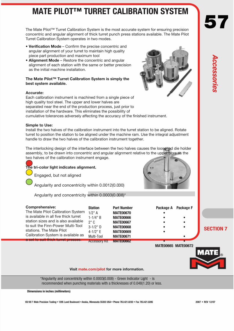
7/30/2019 Catalog Ultrafsdfsdf Tec
http://slidepdf.com/reader/full/catalog-ultrafsdfsdf-tec 57/96
57
Engaged, but not aligned
Angularity and concentricity within 0.0012(0.030)
Angularity and concentricity within 0.0003(0.008)*
• Verification Mode – Confirm the precise concentric and
angular alignment of your turret to maintain high quality
piece part production and maximum tool
• Alignment Mode – Restore the concentric and angular
alignment of each station with the same or better precision
as the initial machine installation.
The Mate Pilot™ Turret Calibration System is simply the
best system available.
Accurate:
Each calibration instrument is machined from a single piece of
high quality tool steel. The upper and lower halves are
separated near the end of the production process, just prior to
installation of the hardware. This eliminates the possibility of
cumulative tolerances adversely affecting the accuracy of the finished instrument.
Simple to Use:
Install the two halves of the calibration instrument into the turret station to be aligned. Rotate
turret to position the station to be aligned under the machine ram. Use the integral adjustment
handle to draw the two halves of the calibration instrument together.
The interlocking design of the interface between the two halves causes the loosened die holder
assembly, to be drawn into concentric and angular alignment relative to the upper bore as the
two halves of the calibration instrument engage.
Comprehensive:
The Mate Pilot Calibration System
is available in all five thick turret
station sizes and is also available
to suit the Finn-Power Multi-Tool
stations. The Mate PilotCalibration System is available as
a set to suit thick turret presses.
The tri-color light indicates alignment.
The Mate Pilot™ Turret Calibration System is the most accurate system for ensuring precision
concentric and angular alignment of thick turret punch press stations available. The Mate Pilot
Turret Calibration System operates in two modes.
Visit mate.com/pilot for more information.
*Angularity and concentricity within 0.0003(0.008) - Green Indicator Light - is
recommended when punching materials with a thicknesses of 0.048(1.20) or less.
SECTION 7
Station Part Number Package A Package F
1/2" A MATE00670 •
1-1/4" B MATE00666 • •
2" C MATE00667 • •
3-1/2" D MATE00668 • •
4-1/2" E MATE00669 •Multi-Tool MATE00671 •
Accessory Kit MATE00662 • •
MATE00665 MATE00672
MATE PILOT™ TURRET CALIBRATION SYSTEM
A c c e s s o r i e s
Dimensions in inches (millimeters)
©2 00 7 Mate Precision Tooling • 1295 Lund Boulevard • Anoka, Minnesota 55303 USA • Phone 763.421.0230 • Fax 763.421.0285 2007 • REV 12/07
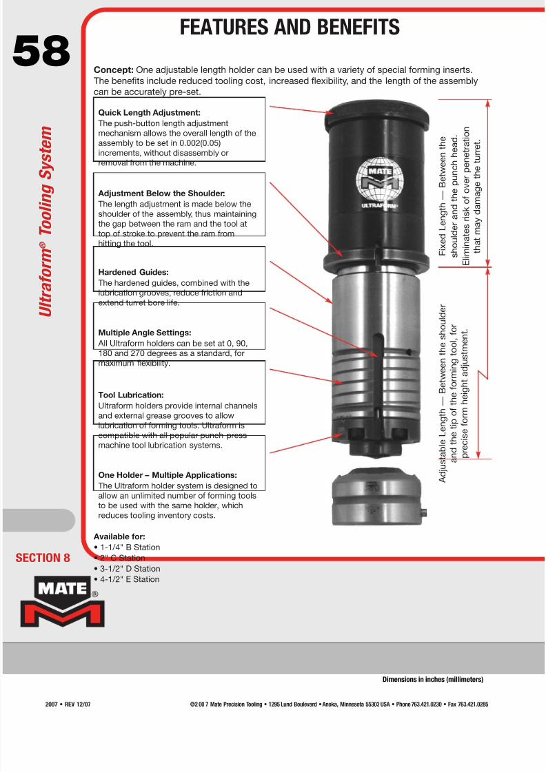
7/30/2019 Catalog Ultrafsdfsdf Tec
http://slidepdf.com/reader/full/catalog-ultrafsdfsdf-tec 58/96
58Concept: One adjustable length holder can be used with a variety of special forming inserts.
The benefits include reduced tooling cost, increased flexibility, and the length of the assembly
can be accurately pre-set.
Available for:
• 1-1/4" B Station
• 2" C Station
• 3-1/2" D Station
• 4-1/2" E Station
A d j u s t a b l e L e n g t h —
B e t w e e n t h e s h o u l d e r
a n d t h e t i p o f t h e f o r m i n g t o o l , f o r
p r e c i s e f o r m h e i g h t a d j u s t m e n t .
F i x e d L e n g t h — B
e t w e e n t h e
s h o u l d e r a n d t h e p u n c h h e a d .
E l i m i n a t e s r i s k o f o v e r p e n e t r a t i o
n
t h a t m a y d a m a g e t h e t u r r e t .
Quick Length Adjustment:
The push-button length adjustment
mechanism allows the overall length of theassembly to be set in 0.002(0.05)
increments, without disassembly or
removal from the machine.
Adjustment Below the Shoulder:
The length adjustment is made below the
shoulder of the assembly, thus maintaining
the gap between the ram and the tool at
top of stroke to prevent the ram from
hitting the tool.
Hardened Guides:The hardened guides, combined with the
lubrication grooves, reduce friction and
extend turret bore life.
Multiple Angle Settings:
All Ultraform holders can be set at 0, 90,
180 and 270 degrees as a standard, for
maximum flexibility.
Tool Lubrication:
Ultraform holders provide internal channelsand external grease grooves to allow
lubrication of forming tools. Ultraform is
compatible with all popular punch press
machine tool lubrication systems.
One Holder – Multiple Applications:
The Ultraform holder system is designed to
allow an unlimited number of forming tools
to be used with the same holder, which
reduces tooling inventory costs.
ECTION 8
U l t r a f o r m ® T o o l i n g S y s t e m
FEATURES AND BENEFITS
Dimensions in inches (millimeters)
©2 00 7 Mate Precision Tooling • 1295 Lund Boulevard • Anoka, Minnesota 55303 USA • Phone 763.421.0230 • Fax 763.421.02852007 • REV 12/07
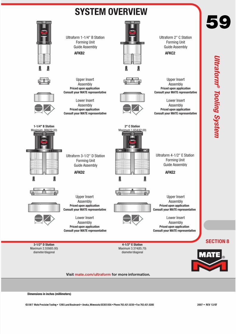
7/30/2019 Catalog Ultrafsdfsdf Tec
http://slidepdf.com/reader/full/catalog-ultrafsdfsdf-tec 59/96
59Ultraform 1-1/4" B Station
Forming Unit
Guide Assembly
Upper Insert
AssemblyPriced upon application
Consult your MATE representative
Lower Insert
AssemblyPriced upon application
Consult your MATE representative
Lower Insert
AssemblyPriced upon application
Consult your MATE representative
Upper Insert
Assembly
Upper Insert
AssemblyPriced upon application
Consult your MATE representative
Lower Insert
AssemblyPriced upon application
Consult your MATE representative
Upper Insert
AssemblyPriced upon application
Consult your MATE representative
Lower Insert
AssemblyPriced upon application
Consult your MATE representative
Ultraform 2" C Station
Forming Unit
Guide Assembly
Ultraform 3-1/2" D Station
Forming Unit
Guide Assembly
Ultraform 4-1/2" E Station
Forming Unit
Guide Assembly
AFKB2 AFKC2
AFKD2 AFKE2
3-1/2" D Station
Maximum 2.559(65.00)
diameter/diagonal
4-1/2" E Station
Maximum 3.374(85.70)
diameter/diagonal
1-1/4" B Station
Maximum .866(22.00)
diameter/diagonal
2" C Station
Maximum 1.654(42.00)
diameter/diagonal
Visit mate.com/ultraform for more information.
Priced upon application
Consult your MATE representative
SECTION 8
SYSTEM OVERVIEW
U l t r a f o r m ®
T o o l i n g S y s t e m
Dimensions in inches (millimeters)
©2 00 7 Mate Precision Tooling • 1295 Lund Boulevard • Anoka, Minnesota 55303 USA • Phone 763.421.0230 • Fax 763.421.0285 2007 • REV 12/07

7/30/2019 Catalog Ultrafsdfsdf Tec
http://slidepdf.com/reader/full/catalog-ultrafsdfsdf-tec 60/96
60
Louver Scissortool® Shearbutton Rollerball®
Sheetmarker® Stamping—Alpha Numeric Stamping—V-line Threadform
Emboss—Formed Emboss—Cold Forged Extrusion—Tapping Extrusion—Flanged Hole
Guided Shearing Hinge Tool Knockout Lance And Form
Countersink—Round Countersink—Shape Emboss—Beading Emboss—Edgeform
Cluster—Round Cluster—Shape Card Guide Centerpoint
See MATE Forming Tool Order
Guide for forming tool ordering
specifications...
Ask for part number
LIT00002
ECTION 8
S p e c i a l A s s e m b l i e s
SPECIAL ASSEMBLIES
©2 00 7 Mate Precision Tooling • 1295 Lund Boulevard • Anoka, Minnesota 55303 USA • Phone 763.421.0230 • Fax 763.421.02852007 • REV 12/07

7/30/2019 Catalog Ultrafsdfsdf Tec
http://slidepdf.com/reader/full/catalog-ultrafsdfsdf-tec 61/96
61Cluster
Use:
To produce multiple holes with minimal hits.
Typical Application:
• Material thickness from 0.020(0.50) to
0.157(4.00).
• Other constraints dependent upon station size,
punch size and shape and press tonnage.
Comments:
• For greater hole uniformity and flatter sheets,
spread the punches to avoid punching
adjacent holes in the same hit.
• Do not re-punch through previously punched
holes to complete a pattern. A single hit toolmay be necessary.
Card Guide
Use:
As a retainer for printed circuit boards.
Typical Application:
• Material thickness from 0.040(1.00) to
0.078(2.00).
• Maximum recommended top-of-sheet to
top-of-form height is 0.125 (3.20).
Comments:
• Length of the card guide is dependent
upon station size and machine tonnage.
• Also available as a continuous form to
increase productivity and flexibility.
Visit mate.com/specialassemblies for more information
SECTION 8
SPECIAL ASSEMBLIES
S p e c i a l A s s e m b l i e s
Dimensions in inches (millimeters)
©2 00 7 Mate Precision Tooling • 1295 Lund Boulevard • Anoka, Minnesota 55303 USA • Phone 763.421.0230 • Fax 763.421.0285 2007 • REV 12/07

7/30/2019 Catalog Ultrafsdfsdf Tec
http://slidepdf.com/reader/full/catalog-ultrafsdfsdf-tec 62/96
62Countersink—Dedicated
Use:
Allows screw and rivet head to sit flush or below the
surface of the material.
Typical Application:
• Material thickness from 0.048(1.22) to 0.250(6.35),
dependent upon press tonnage capacity.
Comments:
• The shoulder (dedicated) style is generally ordered
for one material thickness and screw size.
• The shoulder style coins the surrounding area,
producing a clean flat countersink with minimal burring.
Emboss—Continuous
Use:
As a stiffener to add rigidity to sheet metal
panels.
Typical Application:
• Material thickness from 0.027(0.70) to
0.250(6.35), dependent upon press
tonnage capacity.
Comments:
• The increment between hits is determined
by the cosmetic requirements for the
finished part. Smaller increments result
in improved appearance.
• The form height should be as low as
possible to minimize sheet distortion.
ECTION 8
S p e c i a l A s s e m b l i e s
SPECIAL ASSEMBLIES
Dimensions in inches (millimeters)
©2 00 7 Mate Precision Tooling • 1295 Lund Boulevard • Anoka, Minnesota 55303 USA • Phone 763.421.0230 • Fax 763.421.02852007 • REV 12/07

7/30/2019 Catalog Ultrafsdfsdf Tec
http://slidepdf.com/reader/full/catalog-ultrafsdfsdf-tec 63/96
63Emboss—Cold Forged
Use:
To produce a logo or design on a part.
Typical Application:
• Material thickness from 0.018(0.46) to
0.118(3.00).
• Best results in material thickness from
0.040(1.00) to 0.078(2.00).
• Maximum size dependent on the tooling style,
station size and press tonnage capacity.
Comments:
• An exact drawing, CAD file, or artwork
of logo is required to produce this type
of assembly.
®
Emboss—Formed
Use:
Provides a recess or a protrusion.
Typical Application:• Material thickness from 0.027(0.70) to 0.250(6.35),
dependent upon press tonnage capacity.
Comments:
• Best results are attained when the side wall angle
is 45° or less.
• Optimum form height is 3 x the material thickness
or less.
SECTION 8
Visit mate.com/specialassemblies for more information
SPECIAL ASSEMBLIES
S p e c i a l A s s e m b l i e s
Dimensions in inches (millimeters)
©2 00 7 Mate Precision Tooling • 1295 Lund Boulevard • Anoka, Minnesota 55303 USA • Phone 763.421.0230 • Fax 763.421.0285 2007 • REV 12/07
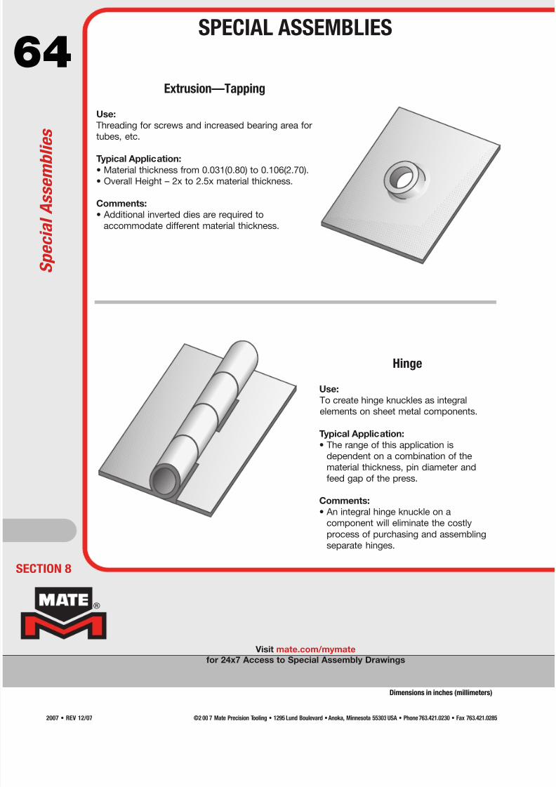
7/30/2019 Catalog Ultrafsdfsdf Tec
http://slidepdf.com/reader/full/catalog-ultrafsdfsdf-tec 64/96
64
Visit mate.com/mymate
for 24x7 Access to Special Assembly Drawings
Extrusion—Tapping
Use:
Threading for screws and increased bearing area for
tubes, etc.
Typical Application:
• Material thickness from 0.031(0.80) to 0.106(2.70).
• Overall Height – 2x to 2.5x material thickness.
Comments:
• Additional inverted dies are required to
accommodate different material thickness.
Hinge
Use:
To create hinge knuckles as integral
elements on sheet metal components.
Typical Application:
• The range of this application is
dependent on a combination of the
material thickness, pin diameter and
feed gap of the press.
Comments:
• An integral hinge knuckle on a
component will eliminate the costly
process of purchasing and assembling
separate hinges.
ECTION 8
S p e c i a l A s s e m b l i e s
SPECIAL ASSEMBLIES
Dimensions in inches (millimeters)
©2 00 7 Mate Precision Tooling • 1295 Lund Boulevard • Anoka, Minnesota 55303 USA • Phone 763.421.0230 • Fax 763.421.02852007 • REV 12/07
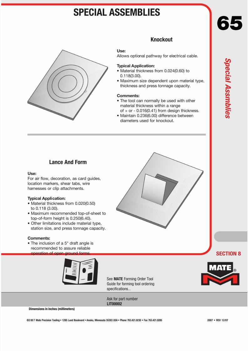
7/30/2019 Catalog Ultrafsdfsdf Tec
http://slidepdf.com/reader/full/catalog-ultrafsdfsdf-tec 65/96
65Knockout
Use:
Allows optional pathway for electrical cable.
Typical Application:
• Material thickness from 0.024(0.60) to
0.118(3.00).
• Maximum size dependent upon material type,
thickness and press tonnage capacity.
Comments:
• The tool can normally be used with other
material thickness within a range
of + or - 0.016(0.41) from design thickness.
• Maintain 0.236(6.00) difference between
diameters used for knockout.
Lance And Form
Use:
For air flow, decoration, as card guides,
location markers, shear tabs, wireharnesses or clip attachments.
Typical Application:
• Material thickness from 0.020(0.50)
to 0.118 (3.00).
• Maximum recommended top-of-sheet to
top-of-form height is 0.250(6.40).
• Other limitations include material type,
station size, and press tonnage capacity.
Comments:
• The inclusion of a 5° draft angle is
recommended to assure reliable
operation of open ground forms.
See MATE Forming Order Tool
Guide for forming tool ordering
specifications...
Ask for part number
LIT00002
SECTION 8
SPECIAL ASSEMBLIES
S p e c i a l A s s m b l i e
s
Dimensions in inches (millimeters)
©2 00 7 Mate Precision Tooling • 1295 Lund Boulevard • Anoka, Minnesota 55303 USA • Phone 763.421.0230 • Fax 763.421.0285 2007 • REV 12/07
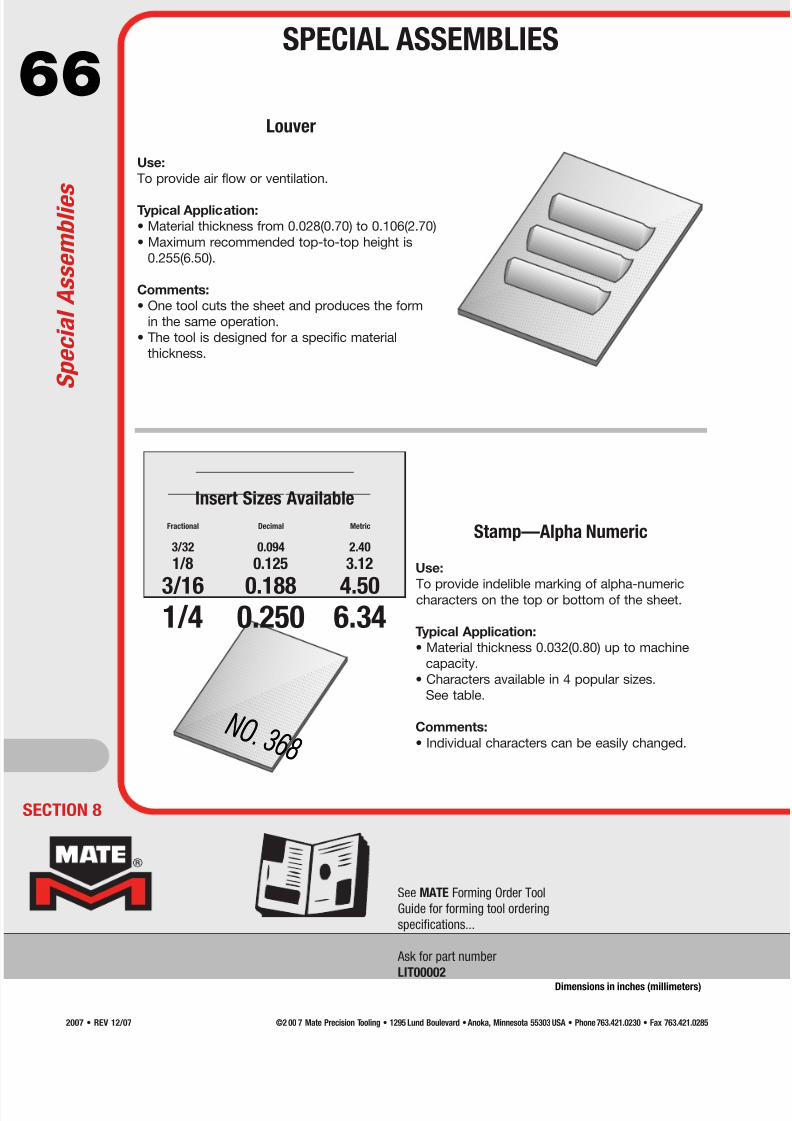
7/30/2019 Catalog Ultrafsdfsdf Tec
http://slidepdf.com/reader/full/catalog-ultrafsdfsdf-tec 66/96
66
See MATE Forming Order Tool
Guide for forming tool ordering
specifications...
Ask for part number
LIT00002
Louver
Use:
To provide air flow or ventilation.
Typical Application:
• Material thickness from 0.028(0.70) to 0.106(2.70)
• Maximum recommended top-to-top height is
0.255(6.50).
Comments:
• One tool cuts the sheet and produces the form
in the same operation.
• The tool is designed for a specific material
thickness.
Stamp—Alpha Numeric
Use:
To provide indelible marking of alpha-numericcharacters on the top or bottom of the sheet.
Typical Application:
• Material thickness 0.032(0.80) up to machine
capacity.
• Characters available in 4 popular sizes.
See table.
Comments:
• Individual characters can be easily changed.
Insert Sizes Available
Fractional Decimal Metric
3/32 0.094 2.40
1/8 0.125 3.12
3/16 0.188 4.501/4 0.250 6.34
N O . 3 6 8 N O . 3 6 8
ECTION 8
S p e c i a l A s s e m b l i e s
SPECIAL ASSEMBLIES
Dimensions in inches (millimeters)
©2 00 7 Mate Precision Tooling • 1295 Lund Boulevard • Anoka, Minnesota 55303 USA • Phone 763.421.0230 • Fax 763.421.02852007 • REV 12/07
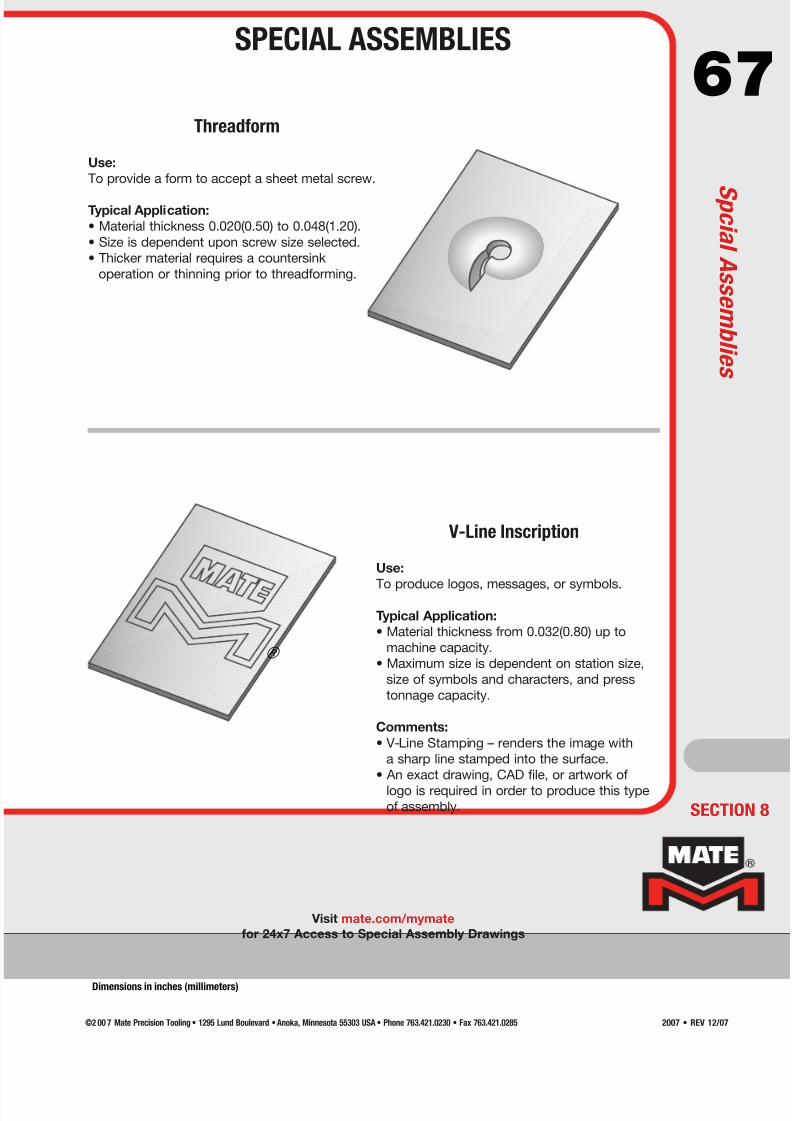
7/30/2019 Catalog Ultrafsdfsdf Tec
http://slidepdf.com/reader/full/catalog-ultrafsdfsdf-tec 67/96
67Threadform
Use:
To provide a form to accept a sheet metal screw.
Typical Application:
• Material thickness 0.020(0.50) to 0.048(1.20).
• Size is dependent upon screw size selected.
• Thicker material requires a countersink
operation or thinning prior to threadforming.
®
Visit mate.com/mymate
for 24x7 Access to Special Assembly Drawings
V-Line Inscription
Use:
To produce logos, messages, or symbols.
Typical Application:
• Material thickness from 0.032(0.80) up to
machine capacity.
• Maximum size is dependent on station size,
size of symbols and characters, and press
tonnage capacity.
Comments:
• V-Line Stamping – renders the image with
a sharp line stamped into the surface.
• An exact drawing, CAD file, or artwork of
logo is required in order to produce this typeof assembly. SECTION 8
SPECIAL ASSEMBLIES
S p c i a l A s s e m b l i e
s
Dimensions in inches (millimeters)
©2 00 7 Mate Precision Tooling • 1295 Lund Boulevard • Anoka, Minnesota 55303 USA • Phone 763.421.0230 • Fax 763.421.0285 2007 • REV 12/07

7/30/2019 Catalog Ultrafsdfsdf Tec
http://slidepdf.com/reader/full/catalog-ultrafsdfsdf-tec 68/96
68
ECTION 8
Mate Rollerball®
Use:
The Rollerball® is an exciting new concept designed
by Mate Precision Tooling to take advantage of theextended programming capabilities of hydraulic and
other punch presses capable of operating in the
x and y axis with the ram down. The Rollerball®
gives you the benefit of making forms not possible
with single hit forming tools.
Typical Application:
• Maximum workable material thickness is
0.105(2.70) mild steel.
Comments:
• The press must be capable of holding the ram
down while the sheet is moved in the x and/or y.
Mate Sheetmarker®
Use:
For markings or etchings on the surface of sheet
metal. The tool uses a diamond pointed insert in a
spring loaded holder to create the marking.
Typical Application:
• The Sheetmarker® Tool can be used on all
material types and thicknesses.
Comments:
• A wide variety of results can be produced,
ranging from very light etching to fairly deep
grooves in the sheet.
• Variations are achieved with a combination of
three spring pressures and two insert point
angles.
Comments:
• The press must be capable of holding the ram
down while the sheet is moved in the x and/or y.
S p e c i a l A s s e m b l i e s
SPECIAL ASSEMBLIES
Visit mate.com/mymate
for 24x7 Access to Special Assembly Drawings
Dimensions in inches (millimeters)
©2 00 7 Mate Precision Tooling • 1295 Lund Boulevard • Anoka, Minnesota 55303 USA • Phone 763.421.0230 • Fax 763.421.02852007 • REV 12/07
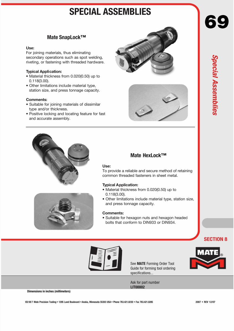
7/30/2019 Catalog Ultrafsdfsdf Tec
http://slidepdf.com/reader/full/catalog-ultrafsdfsdf-tec 69/96
69
SECTION 8
See MATE Forming Order Tool
Guide for forming tool ordering
specifications...
Ask for part number
LIT00002
Mate SnapLock™
Use:
For joining materials, thus eliminating
secondary operations such as spot welding,riveting, or fastening with threaded hardware.
Typical Application:
• Material thickness from 0.020(0.50) up to
0.118(3.00).
• Other limitations include material type,
station size, and press tonnage capacity.
Comments:
• Suitable for joining materials of dissimilar
type and/or thickness.
• Positive locking and locating feature for fast
and accurate assembly.
Mate HexLock™
Use:
To provide a reliable and secure method of retaining
common threaded fasteners in sheet metal.
Typical Application:
• Material thickness from 0.020(0.50) up to
0.118(3.00).
• Other limitations include material type, station size,
and press tonnage capacity.
Comments:
• Suitable for hexagon nuts and hexagon headed
bolts that conform to DIN933 or DIN934.
SPECIAL ASSEMBLIES
S p e c i a l A s s e m b l i e s
Dimensions in inches (millimeters)
©2 00 7 Mate Precision Tooling • 1295 Lund Boulevard • Anoka, Minnesota 55303 USA • Phone 763.421.0230 • Fax 763.421.0285 2007 • REV 12/07
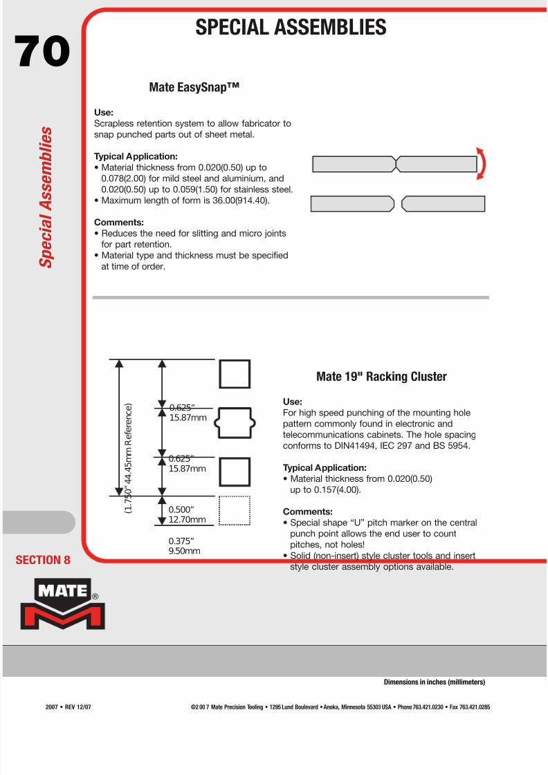
7/30/2019 Catalog Ultrafsdfsdf Tec
http://slidepdf.com/reader/full/catalog-ultrafsdfsdf-tec 70/96
70Mate EasySnap™
Use:
Scrapless retention system to allow fabricator to
snap punched parts out of sheet metal.
Typical Application:
• Material thickness from 0.020(0.50) up to
0.078(2.00) for mild steel and aluminium, and
0.020(0.50) up to 0.059(1.50) for stainless steel.
• Maximum length of form is 36.00(914.40).
Comments:
• Reduces the need for slitting and micro joints
for part retention.
• Material type and thickness must be specified
at time of order.
0.625”15.87mm
0.500”
12.70mm
) e c n e r e f e R
m m 5 4 . 4 4 ” 0 5 7 . 1 (
0.625”
15.87mm
0.375”9.50mm
Mate 19" Racking Cluster
Use:
For high speed punching of the mounting hole
pattern commonly found in electronic and
telecommunications cabinets. The hole spacing
conforms to DIN41494, IEC 297 and BS 5954.
Typical Application:
• Material thickness from 0.020(0.50)
up to 0.157(4.00).
Comments:
• Special shape “U” pitch marker on the central
punch point allows the end user to count
pitches, not holes!• Solid (non-insert) style cluster tools and insert
style cluster assembly options available.ECTION 8
Dimensions in inches (millimeters)
S p e c i a l A s s e m b l i e s
SPECIAL ASSEMBLIES
©2 00 7 Mate Precision Tooling • 1295 Lund Boulevard • Anoka, Minnesota 55303 USA • Phone 763.421.0230 • Fax 763.421.02852007 • REV 12/07
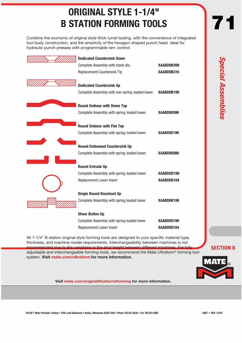
7/30/2019 Catalog Ultrafsdfsdf Tec
http://slidepdf.com/reader/full/catalog-ultrafsdfsdf-tec 71/96
71Combine the economy of original style thick turret tooling, with the convenience of integrated
tool body construction, and the simplicity of the hexagon shaped punch head. Ideal for
hydraulic punch presses with programmable ram control.
Dedicated Countersink DownComplete Assembly with blank die. XAABD0B399
Replacement Countersink Tip XAABD0B316
Dedicated Countersink Up
Complete Assembly with non-spring loaded lower. XAABD0B199
Round Emboss with Dome Top
Complete Assembly with spring loaded lower. XAABD0E099
Round Emboss with Flat Top
Complete Assembly with spring loaded lower. XAABD0E199
Round Embossed Countersink Up
Complete Assembly with spring loaded lower. XAABD0E999
Round Extrude Up
Complete Assembly with spring loaded lower. XAABD0D199
Replacement Lower Insert XAABD0D104
Single Round Knockout Up
Complete Assembly with spring loaded lower XAABD0K199
Shear Button Up
Complete Assembly with spring loaded lower XAABD0S199
Replacement Lower Insert XAABD0S104
All 1-1/4" B station original style forming tools are designed to your specific material type,
thickness, and machine model requirements. Interchangeability between machines is not
recommended due to the variations in the shut height between different machines. For fully
adjustable and interchangeable forming tools, we recommend the Mate Ultraform® forming tool
system. Visit mate.com/ultraform for more information.
Visit mate.com/originalthickturretforming for more information.
SECTION 8
ORIGINAL STYLE 1-1/4"
B STATION FORMING TOOLS
S p e c i a l A s s e m b l i e s
©2 00 7 Mate Precision Tooling • 1295 Lund Boulevard • Anoka, Minnesota 55303 USA • Phone 763.421.0230 • Fax 763.421.0285 2007 • REV 12/07

7/30/2019 Catalog Ultrafsdfsdf Tec
http://slidepdf.com/reader/full/catalog-ultrafsdfsdf-tec 72/96
72
Die clearance is equal to the space between punch and die when
the punch enters the die opening.
Regardless of sheet thickness, the recommended penetration of
the punch into a Slug Free® die is 0.118(3.00).
WHAT IS DIE CLEARANCE?
ANATOMY OF A PUNCHED HOLE
Rollover Depth - (RD) Total Clearance - (TC)
MaterialThickness
Burr Height - (BH)
Rollover Width - (RW)
Burnish Land - (BL)
CLEARANCE TOO SMALL —secondary shear cracks are created, raising punching
force, and shortening tool life.
PUNCH
DIEDIE
SHEAR CRACK
MATERIAL
PUNCH
DIE
DIE CLEARANCE
DieClearance 2
DieClearance 1
Total Die Clearance = Die Clearance on both sides of punch
Total Die Clearance = Die Clearance 1 + Die Clearance 2
PROPER CLEARANCE —shear cracks join, balancing punching force, piece part
quality, and tool life.
PUNCH
DIEDIE
MATERIAL
SHEAR CRACK
WHY USE PROPER DIE CLEARANCE?
MATE always refers to TOTAL DIE CLEARANCE
— NOT clearance per side.
Blanking Tools are used to punch out a small part down the slug chute. Piercing Blanking
Material Type(Typical Shear Strength)
Material Thickness (T)Total Die Clearance
(% of T)Total Die Clearance
(% of T)
Aluminum
25,000 psi(0.172 kN/mm2)
Less than 0.098(2.50) 15% 15%
0.098(2.50) to 0.197(5.00) 20% 15%
Greater than 0.197(5.00) 25% 20%
Mild Steel50,000 psi
(0.344 kN/mm2)
Less than 0.118(3.00) 20% 15%
0.118(3.00) to 0.237(6.00) 25% 20%
Greater than 0.237(6.00) 30% 20%
Stainless Steel75,000 psi
(0.517 kN/mm2)
Less than 0.059(1.50) 20% 15%
0.059(1.50) to 0.110(2.80) 25% 20%
0.110(2.80)to 0.157(4.00) 30% 20%
Greater than 0.157(4.00) 35% 25%
ECTION 9
Dimensions in inches (millimeters)
D i e C l e a r a n c e
DIE CLEARANCE
©2 00 7 Mate Precision Tooling • 1295 Lund Boulevard • Anoka, Minnesota 55303 USA • Phone 763.421.0230 • Fax 763.421.02852007 • REV 12/07
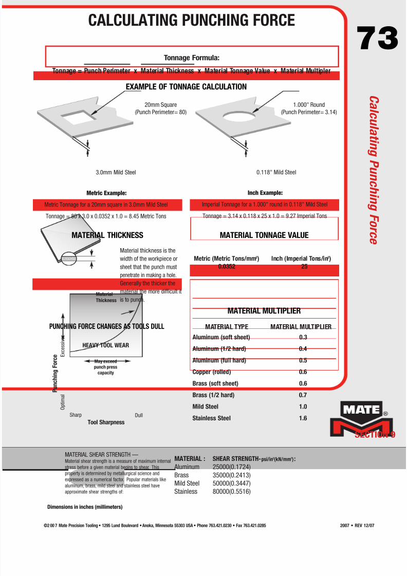
7/30/2019 Catalog Ultrafsdfsdf Tec
http://slidepdf.com/reader/full/catalog-ultrafsdfsdf-tec 73/96
73
MATERIAL TONNAGE VALUE
MATERIAL MULTIPLIER
MATERIAL THICKNESS
Material
Thickness
MATERIAL SHEAR STRENGTH —MATERIAL :
Aluminum
Brass
Mild Steel
Stainless
SHEAR STRENGTH-psi/in2(kN/mm2):
25000(0.1724)
35000(0.2413)
50000(0.3447)
80000(0.5516)
PUNCHING FORCE CHANGES AS TOOLS DULL
HEAVY TOOL WEAR
May exceed
punch press
capacity
Sharp Dull
Tool Sharpness
O p t i m a l
E x c e s s i v e
P u n c h i n g
F o r c e
Material thickness is the
width of the workpiece or
sheet that the punch must
penetrate in making a hole.
Generally the thicker the
material the more difficult it
is to punch.
Material shear strength is a measure of maximum internal
stress before a given material begins to shear. This
property is determined by metallurgical science and
expressed as a numerical factor. Popular materials like
aluminum, brass, mild steel and stainless steel have
approximate shear strengths of:
Metric Example:
Metric Tonnage for a 20mm square in 3.0mm Mild Steel
Tonnage = 80 x 3.0 x 0.0352 x 1.0 = 8.45 Metric Tons
Inch Example:
Imperial Tonnage for a 1.000" round in 0.118" Mild Steel
Tonnage = 3.14 x 0.118 x 25 x 1.0 = 9.27 Imperial Tons
EXAMPLE OF TONNAGE CALCULATION
3.0mm Mild Steel
Metric (Metric Tons/mm2) Inch (Imperial Tons/in2)
0.0352 25
Aluminum (soft sheet) 0.3
Aluminum (1/2 hard) 0.4
Aluminum (full hard) 0.5
Copper (rolled) 0.6
Brass (soft sheet) 0.6
Brass (1/2 hard) 0.7
Mild Steel 1.0
Stainless Steel 1.6
MATERIAL TYPE MATERIAL MULTIPLIER
20mm Square
(Punch Perimeter= 80)
0.118" Mild Steel
Tonnage Formula:
Tonnage = Punch Perimeter x Material Thickness x Material Tonnage Value x Material Multipler
SECTION 9
1.000" Round
(Punch Perimeter= 3.14)
CALCULATING PUNCHING FORCE
C a l c u l a t i n g P u n c h i n g F o r c e
Dimensions in inches (millimeters)
©2 00 7 Mate Precision Tooling • 1295 Lund Boulevard • Anoka, Minnesota 55303 USA • Phone 763.421.0230 • Fax 763.421.0285 2007 • REV 12/07

7/30/2019 Catalog Ultrafsdfsdf Tec
http://slidepdf.com/reader/full/catalog-ultrafsdfsdf-tec 74/96
74
ECTION 9
Station 1/2" A 1-1/4" B 2" C 3-1/2" D 4-1/2" E
Maximum Punch Diagonal 0.500(12.70) 1.250(31.75) 2.000(50.80) 3.500(88.90) 4.500(114.30)
Ultra TEC Punch
Part Number PAUA PAUB PAAC PAAD PAAE
Overall Length 4.245(107.82) 3.957(100.51) 3.786(96.16) 3.313(84.15) 3.353(85.17)Shank Diameter 0.630(15.99) 1.250(31.75) 2.007(50.98) 3.520(89.41) 4.520(114.81)
Straight Before Radius* 0.742(18.85) 0.742(18.85) 1.004(25.50) 1.004(25.50) 1.043(26.49)
Ultra TEC Stripper
Part Number S6KA S6KB S6KC S6KD S6KE
Outside Diameter 0.751(19.07) 1.500(38.10) 2.249(57.12) 3.825(97.16) 4.759(120.88)
Thickness 0.272(6.91) 0.272(6.91) 0.394(10.01) 0.394(10.01) 0.394(10.01)
Stripper Land 0.157(3.99) 0.157(3.99) 0.315(8.00) 0.315(8.00) 0.315(8.00)
Metric (Original) Style Punch
Part Number PAAA PAAB PAAC PAAD PAAE
Overall Length 8.169(207.49) 8.169(207.49) 3.786(96.16) 3.313(84.15) 3.353(85.17)Shank Diameter 0.630(16.00) 1.250(31.75) 2.007(50.98) 3.520(89.41) 4.520(114.81)
Straight Before Radius* 0.664(16.87) 0.742(18.85) 1.004(25.50) 1.004(25.50) 1.043(26.49)
Original Style Stripper
Part Number S6AA S6AB S6AC S6AD S6AE
Guide/Stripper Outside D iameter 1.020(25.91) 1.883(47.83) 2.007(50.98) 3.520(89.41) 4.520(114.81)
Guide Length/Stripper Thickness 4.448(112.98) 4.528(115.01) 0.394(10.01) 0.394(10.01) 0.394(10.01)
Stripper Land 0.197(5.00) 0.197(5.00) 0.394(10.01) 0.394(10.01) 0.394(10.01)
Slug Free® Die
Part Number D0AA D0AB D0AC D0AD D0AE
Outside Diameter 1.000(25.40) 1.875(47.63) 3.500(88.90) 4.938(125.43) 6.249(158.72)
Overall Height 1.187(30.15) 1.187(30.15) 1.187(30.15) 1.187(30.15) 1.187(30.15)
Die Penetration 0.118(3.00) 0.118(3.00) 0.118(3.00) 0.118(3.00) 0.118(3.00)
C r i t i c a l D i m e n s i o n s
THICK TURRET TOOLINGCRITICAL DIMENSIONS
* The Straight Before Radius (SBR) dimension may be reduced for smalldiameters and narrow widths. Consult your application specialists.
Shank Diameter
S t r a i g h t B e f o r e
R a d i u s
O v e r a l l L e n g t h
Shank
Diameter
S t r a i g h t B e f o r e
R a d i u s
O v e r a l l L e n g t h
G u i d e L e n g t h
Outside Diameter
S t r i p p e r L a n d
Outside Diameter
D i e
P e n e t r
a t i o n
O v e r a l l H e i g h t
Outside Diameter S t r i p p e r L a n d
T h i c k n e s s
©2 00 7 Mate Precision Tooling • 1295 Lund Boulevard • Anoka, Minnesota 55303 USA • Phone 763.421.0230 • Fax 763.421.02852007 • REV 12/07
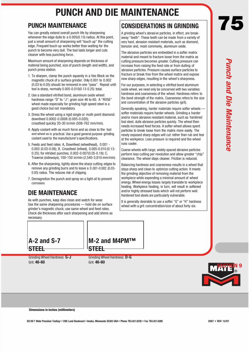
7/30/2019 Catalog Ultrafsdfsdf Tec
http://slidepdf.com/reader/full/catalog-ultrafsdfsdf-tec 75/96
75PUNCH MAINTENANCE You can greatly extend overall punch life by sharpening
whenever the edge dulls to a 0.005(0.13) radius. At this point,
just a small amount of sharpening will “touch up” the cutting
edge. Frequent touch up works better than waiting for the
punch to become very dull. The tool lasts longer and cuts
cleaner with less punching force.
Maximum amount of sharpening depends on thickness ofmaterial being punched, size of punch (length and width), and
punch press station.
1. To sharpen, clamp the punch squarely in a Vee Block on the
magnetic chuck of a surface grinder. Only 0.001 to 0.002
(0.03 to 0.05) should be removed in one “pass”. Repeat until
tool is sharp, normally 0.005-0.010(0.13-0.25) total.
2. Use a standard vitrified bond, aluminum oxide wheel:
hardness range “D” to “J”; grain size 46 to 60. A “ROSE”
wheel made especially for grinding high speed steel is a
good choice but not mandatory.
3. Dress the wheel using a rigid single or multi-point diamond:
downfeed 0.0002-0.0008 (0.005-0.020);
crossfeed quickly 20-30 in/min (508-762 mm/min).
4. Apply coolant with as much force and as close to the tool
and wheel as is practical. Use a good general purpose grinding
coolant used to the manufacturer's specifications.
5. Feeds and feed rates: A, Downfeed (wheelhead), 0.001 -
0.003 (0.03-0.08); B, Crossfeed (infeed), 0.005-0.010 (0.13-
0.25); for nitrided punches, 0.002-0.007(0.05-0.18); C,
Traverse (sideways), 100-150 in/min (2,540-3,810 mm/min).
6. After the sharpening, lightly stone the sharp cutting edges to
remove any grinding burrs and to leave a 0.001-0.002 (0.03-
0.05) radius. This reduces risk of chipping.
7. Demagnetize the punch and spray on a light oil to prevent
corrosion.
DIE MAINTENANCE As with punches, keep dies clean and watch for wear.
Use the same sharpening procedures –– hold die on surface
grinder's magnetic chuck; use same wheel and feed rates.
Check die thickness after each sharpening and add shims as
necessary.
CONSIDERATIONS IN GRINDING A grinding wheel's abrasive particles, in effect, are break-
away “teeth”. These teeth can be made from a variety of
very hard, abrasion resistant materials, such as diamond,
borozon and, most commonly, aluminum oxide.
The abrasive particles are embedded in a softer matrix
material and meant to fracture loose from the matrix as
cutting pressure becomes greater. Cutting pressure canincrease from raising the feed rate or from dulling of
abrasive particles. Pressure causes surface particles to
fracture or break free from the wheel matrix and expose
new sharp edges, resulting in the wheel's sharpness.
For our purposes, in selecting a vitrified bond aluminum
oxide wheel, we need only be concerned with two variables:
hardness and coarseness of the wheel. Hardness refers to
the bond strength of the matrix. Coarseness refers to the size
and concentration of the abrasive particles (grit).
Generally speaking, harder materials require softer wheels ––
softer materials require harder wheels. Grinding a harder
and/or more abrasive resistant material, such as hardened
tool steel, dulls abrasive particles quickly. The wheel thenneeds increased feed forces. A softer wheel allows spent
particles to break loose from the matrix more easily. The
newly exposed sharp edges will cut rather than rub and tear
at the workpiece. Less pressure is required and the wheel
runs cooler.
Coarse wheels with large, widely spaced abrasive particles
perform less cutting per revolution and allow greater “chip”
clearance. The wheel stays cleaner. Friction is reduced.
Balancing hardness and coarseness results in a wheel that
stays sharp and clean to optimize cutting action. It meets
the grinding objective of removing material from the
workpiece while expending a minimal amount of wheel
energy. Wheel energy losses largely translate to workpiece
heating. Workpiece heating, in turn, will result in softened
and/or highly stressed tools which will not perform well.
Hardened tool steels are particularly vulnerable.
It is generally desirable to use a softer “G” or “H” hardness
wheel with a grit concentration/size of about forty-six.
A-2 and S-7
STEELGrinding Wheel Hardness: G-J
Grit: 46-60
M-2 and M4PM™
STEELGrinding Wheel Hardness: D-G
Grit: 46-60SECTION 9
PUNCH AND DIE MAINTENANCE
P u n c h a n d D i e M
a i n t e n a n c e
Dimensions in inches (millimeters)
©2 00 7 Mate Precision Tooling • 1295 Lund Boulevard • Anoka, Minnesota 55303 USA • Phone 763.421.0230 • Fax 763.421.0285 2007 • REV 12/07

7/30/2019 Catalog Ultrafsdfsdf Tec
http://slidepdf.com/reader/full/catalog-ultrafsdfsdf-tec 76/96

7/30/2019 Catalog Ultrafsdfsdf Tec
http://slidepdf.com/reader/full/catalog-ultrafsdfsdf-tec 77/96
77
Costs for bolts and lockwashers
can be eliminatedif thread forms can be programmed
into a part. This domed shape with a
screw thread acts like a locknut as a
screw tightens it down. Mate's
special thread form tools make both the screw hole and the
raised dome in one hit.
For access
panels that
fasten with
screws
Screw-pockets in the edge of one panel, coupled withscrew holes in a joining panel, make a quick job out of
preparing a removable panel on the punch press. No nuts
needed. The screw pocket is formed in one hit by a lance
and form tool assembly available in sizes to accommodate
economical standard screws.
Tearing or splitting of
overstressed metal formscan be reduced by placing the form on the sheet with the
grain running perpendicular to the form. Corners of high
louvers, high extrusions, complex lance-and-forms, and card
guides are typically vulnerable to this effect. Liberal
application of a forming lubricant is also recommended to let
the metal slide more freely over the forming surface of thetool, especially in stainless steel.
Parts to be welded can be
positioned preciselywhen shearbuttons are programmed into surfaces to be
joined. Layers of material come together with CNC
accuracy. A 0.200(5.1) dia. shearbutton in one part fits
snugly into a 0.205(5.2) hole in the joining part. Complex
assemblies can become self-jigging. Welding with parts
locked in position greatly reduces assembly time andeliminates many costly fixtures.
When galling occurs on
punch tips(Galling is an adhesion to the punch
tip of metal being punched, caused
by pressure and heat)
The best technique for removing
galling is to rub it off with a fine
stone (India Oil Stone STO29807).
The rubbing should be done parallel
to the direction of the punching
motion. This will polish the surface which contacts thematerial, decreasing the chance of any future galling. Do not
sandblast, belt sand or use other harsh abrasive methods.
These create a coarse surface finish to which material
adheres more easily to the tool.
9 radii in one
auto index toolNo job shop should be
without one. Nine popular
radii or customize.
B
C
A
Three methods for separating
parts using long, narrow
rectanglesSHAKE-AND-BREAK –– By programming a small gap between
hits at exterior corners (A), the corners remain connected to
the sheet until removed from the press and shaken loose. This
technique works where corners of four parts meet.
By programming a larger gap adjacent to interior corners (B), a
special tab tool can transform the gap into a 0.008(0.2)
shake-and-break connection. Just one tangent or radial tool
makes a tab at any corner without rotating when the corner is
made by the shearing tool perpendicular to the tab tool.
If exterior corners don't need to remain connected (C),
the 4-way corner rounding tool cuts and rounds all four
corners in one hit. Tips are specially tapered to blend the
corner radius into the sides – also available with shake-and-
break tab tips.
A
B
C
SECTION 9
PRODUCTIVITY IMPROVEMENTS TIPS AND TECHNIQUES
T i p s a n d T e c h n i q u e s
Dimensions in inches (millimeters)
©2 00 7 Mate Precision Tooling • 1295 Lund Boulevard • Anoka, Minnesota 55303 USA • Phone 763.421.0230 • Fax 763.421.0285 2007 • REV 12/07

7/30/2019 Catalog Ultrafsdfsdf Tec
http://slidepdf.com/reader/full/catalog-ultrafsdfsdf-tec 78/96
78
A. Shape and hit B. Shape and hit C. Shape and hit81-6 7 651-4 1&2 3
1
3
2
5
6
4
78 8 1 231
4
2
3
5
6
6
MOST
LEAST
.020(0.5)
.030(0.8)
THIN NORMAL THICK
FREQUENCYOF
OCCURENCEAND
WORKABILITY
.060(1.5)
.130(3.3)
.250(6.4)
TOP VIEW
T
3TMin.
6T Min. 3T+rMin.r
SIDE VIEW
A.
B.1 1
2
2
How to punch large holes without
exceeding press punching force
Tooling is available for round holes up to 4.500(114.3)
diameter. Such holes can exceed press capacities, especially
in high shear strength materials. Creating large holes with
more than one hit may solve the problem. Using smaller tools
to break long perimeters can cut punching force by a half or
more, without resorting to nibbling a rough hole with a radius
punch. Many tools may be available among the tools you
already have. Others can be ordered to fill out your plan. The
diagrams above use rounds, “DDs”, a quad radius and a
biconvex radius. In all three, slugs fall away through die,
leaving no scrap on the punch press table.
If punches overheat... A. Use a lubricant. This will decrease friction. If lubricant is
unacceptable or if slug pulling occurs:
B. Use more than one punch of the same size in the
sequence. By rotating the punches, there will be a longer
time for each punch to cool down before it is used again.
C. Simply give the tool a rest. Plan the program so that the
tool that is overheating alternates with different punches.
Or stop the press for awhile.
What constitutes “normal” sheet
metal?Thickness: 0.030-0.130(0.80-3.30)
Shear strength: 25,000-75,000 psi (0.172-0.157 kN/mm2)
Normal sheet metal will provide the most trouble-free
operation and longest tool life.
Material that is not in the normal range but still within the
capacity of the punch press may require special tools, high
lubrication, multiple hits and/or other procedures to produce a
satisfactory job. Call Mate customer service for suggestions.
Recommended minimum
distances between holes,
forms and edges of sheetsIf holes and forms are placed any closer to each other or
to edges of sheets than shown below, they will distort
each other and the material because material flows when
it is punched or formed.
A handy shape for punching
large, round holesThis biconvex or lenticular shaped tooling
can be made with the exact radius for the
hole you need. If the hole is larger than
press capacity, we recommend using the
tool with tool rotation (A). Program the
tool for bridge hitting around the perimeterof the circle. If the hole falls within press
capacity, a radial tool and a tangent tool
can punch holes in four hits at less than
half the punching force required for a full
size round and without tool rotation (B).
What to do about tool alignmentIf alignment of your punch press deteriorates to the point where
tools dull too rapidly or workpiece quality is unacceptable, here
are things you can check and fix:
A. Examine tool loading equipment for wear and damage. Adjust
where possible. Replace where necessary.
Clean and lubricate linkages.B. Examine tool receptacles. Clean so that tools seat accurately
and rigidly. Restore damaged or worn components. Check
keys and keyways for proper clearance.
C. Keep your machine manual handy – refer to it regularly.
Minimum 2 x Material Thickness
Minimum 2-1/2 x Material Thickness
T = Material Thickness
ECTION 9
T i p s a n d T e c h n i q u e s
PRODUCTIVITY IMPROVEMENTS TIPS AND TECHNIQUES
Dimensions in inches (millimeters)
©2 00 7 Mate Precision Tooling • 1295 Lund Boulevard • Anoka, Minnesota 55303 USA • Phone 763.421.0230 • Fax 763.421.02852007 • REV 12/07
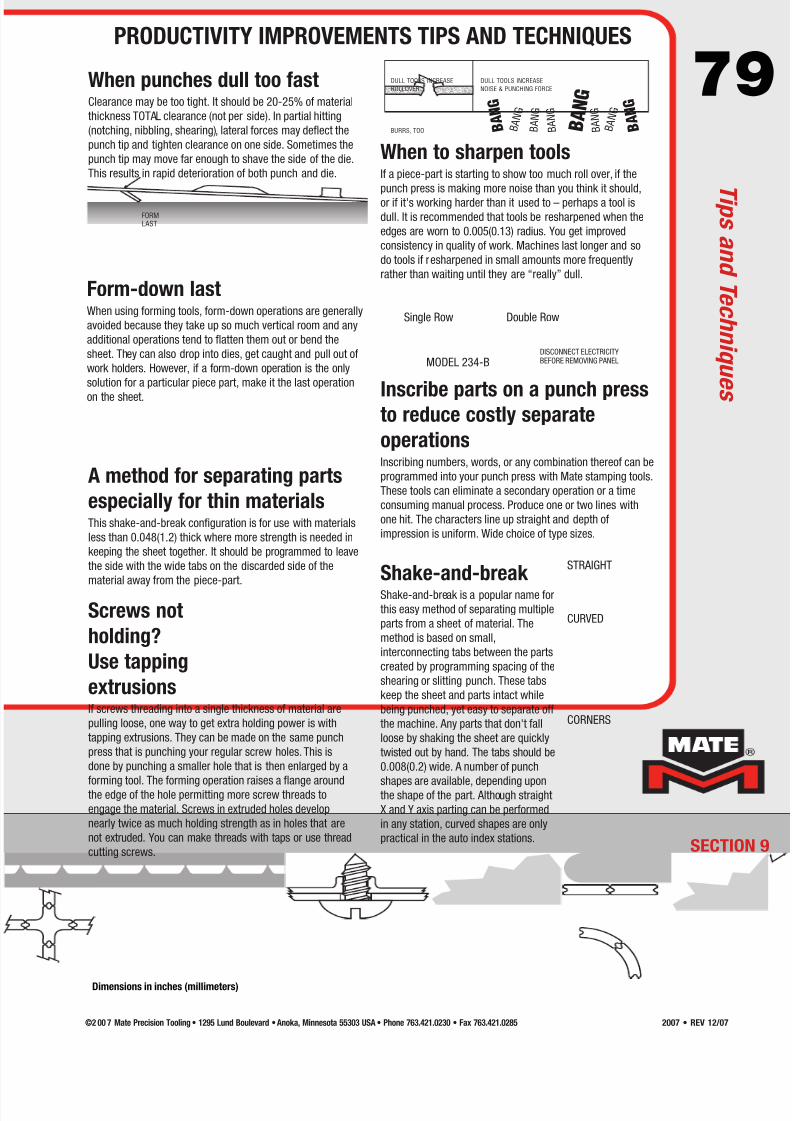
7/30/2019 Catalog Ultrafsdfsdf Tec
http://slidepdf.com/reader/full/catalog-ultrafsdfsdf-tec 79/96
79
FORMLAST
DULL TOOLS INCREASE
ROLLOVER...
DULL TOOLS INCREASE
NOISE & PUNCHING FORCE
B A N G
B A N
G
B A N G
B A N G
B A N G
B A N G
B A N
G
B A N G
BURRS, TOO
Shake-and-break Shake-and-break is a popular name for
this easy method of separating multiple
parts from a sheet of material. The
method is based on small,
interconnecting tabs between the parts
created by programming spacing of the
shearing or slitting punch. These tabs
keep the sheet and parts intact while
being punched, yet easy to separate off
the machine. Any parts that don't fall
loose by shaking the sheet are quickly
twisted out by hand. The tabs should be
0.008(0.2) wide. A number of punch
shapes are available, depending uponthe shape of the part. Although straight
X and Y axis parting can be performed
in any station, curved shapes are only
practical in the auto index stations.
When to sharpen toolsIf a piece-part is starting to show too much roll over, if the
punch press is making more noise than you think it should,
or if it's working harder than it used to – perhaps a tool is
dull. It is recommended that tools be resharpened when the
edges are worn to 0.005(0.13) radius. You get improved
consistency in quality of work. Machines last longer and so
do tools if resharpened in small amounts more frequently
rather than waiting until they are “really” dull.
When punches dull too fastClearance may be too tight. It should be 20-25% of material
thickness TOTAL clearance (not per side). In partial hitting
(notching, nibbling, shearing), lateral forces may deflect the
punch tip and tighten clearance on one side. Sometimes the
punch tip may move far enough to shave the side of the die.
This results in rapid deterioration of both punch and die.
Screws not
holding?
Use tapping
extrusionsIf screws threading into a single thickness of material are
pulling loose, one way to get extra holding power is with
tapping extrusions. They can be made on the same punch
press that is punching your regular screw holes. This is
done by punching a smaller hole that is then enlarged by a
forming tool. The forming operation raises a flange aroundthe edge of the hole permitting more screw threads to
engage the material. Screws in extruded holes develop
nearly twice as much holding strength as in holes that are
not extruded. You can make threads with taps or use thread
cutting screws.
Form-down lastWhen using forming tools, form-down operations are generally
avoided because they take up so much vertical room and any
additional operations tend to flatten them out or bend the
sheet. They can also drop into dies, get caught and pull out of
work holders. However, if a form-down operation is the only
solution for a particular piece part, make it the last operation
on the sheet. Inscribe parts on a punch pressto reduce costly separate
operationsInscribing numbers, words, or any combination thereof can be
programmed into your punch press with Mate stamping tools.
These tools can eliminate a secondary operation or a time
consuming manual process. Produce one or two lines with
one hit. The characters line up straight and depth of
impression is uniform. Wide choice of type sizes.
STRAIGHT
CURVED
CORNERS
Single Row Double Row
MODEL 234-BDISCONNECT ELECTRICITYBEFORE REMOVING PANEL
A method for separating parts
especially for thin materialsThis shake-and-break configuration is for use with materials
less than 0.048(1.2) thick where more strength is needed in
keeping the sheet together. It should be programmed to leave
the side with the wide tabs on the discarded side of the
material away from the piece-part.
SECTION 9
PRODUCTIVITY IMPROVEMENTS TIPS AND TECHNIQUES
T i p s a n d T e c h n i q u e s
Dimensions in inches (millimeters)
©2 00 7 Mate Precision Tooling • 1295 Lund Boulevard • Anoka, Minnesota 55303 USA • Phone 763.421.0230 • Fax 763.421.0285 2007 • REV 12/07

7/30/2019 Catalog Ultrafsdfsdf Tec
http://slidepdf.com/reader/full/catalog-ultrafsdfsdf-tec 80/96
80HIT
NEXT HITPUNCH DIE
1 1 1 1 1
1 1 1 1 1
1 1 1 1 1
1 1 1 1 1
2 2 2 2 2
2 2 2 2 2
2 2 2 2 2
2 2 2 2 2
Here's how to punch huge, smooth
holes in your auto index stationUsing a punch and die with an arc for a much larger circle,
your auto index station can nibble a smooth edged, round
hole limited only by your sheet size. The example shown
above is Mate's quad radius tool for the four circle sizes shown. You
can nibble larger holes with this tool, but scalloping will appear the
more the hole size deviates from
the punch size. You can order any custom radius you wish.
Combating material warpageIf you're punching a large number of holes in a sheet and the
sheet does not stay flat, it could be caused by the cumulative
effect of punching. Each time a hole is punched, material
surrounding the hole is stretched downward, placing the top of the
sheet in tension. The downward movement causes a
corresponding compression at the bottom of the sheet. For a few
holes, the effect is insignificant, but as the number of holes
increases the tension and compression can multiply to the point
where the sheet deforms.
One way to counteract this effect is to punch every other hole first
and then come back and punch the remaining holes. This places
the same amount of force on the sheet, but it disruptstension/compression accumulation that occurs when punching
operations follow one another in close succession and in the same
direction. It also allows the first set of holes to absorb some of the
distorting effect of the second set.
To get rid of the small “teeth” left on edges by rectangular
tools, it is a common practice to order oval punches with
rectangular dies having radiused corners for slitting and
parting. The radii blend into the next cut more smoothly
even on older machines with play in the toolholder bores
and workholders. Workpieces are less likely to cause cuts
and scratches when being handled, need less finishing
work later.
Making accurate butt joints inmetal is easy if you cut both
tab and slot in the same hitThis practice cuts a modified dovetail joint out of the metal
that leaves both pieces flush with each other on the sides
and on the ends. The trick is to position the pieces to be
joined next to each other on the sheet so that the mating
edges can be parted with a single row of hits. Then
program the hits to overlap 0.005(0.10) end to end and
position alternate hits to be offset one material thickness
side to side.
A smooth slitting tip…
MATERIALTHICKNESS
OVERLAP ENDS .005(0.1)
The secret to fine quality
custom stamped inscriptions
If you want your company logo or other symbol to look thebest it possibly can, there is no substitute for good artwork.
That means a well executed drawing rendered with crisp,
clean lines. Providing a high quality CAD file will assure your
custom stamping tool is exactly to your specifications.
ø20.00(508.0)
ø16.00
(406.4)
ø12.00
(304.8)
ø8.00
(203.2)
ECTION 9
T i p s a n d T e c h n i q u e s
PRODUCTIVITY IMPROVEMENTS TIPS AND TECHNIQUES
Dimensions in inches (millimeters)
©2 00 7 Mate Precision Tooling • 1295 Lund Boulevard • Anoka, Minnesota 55303 USA • Phone 763.421.0230 • Fax 763.421.02852007 • REV 12/07
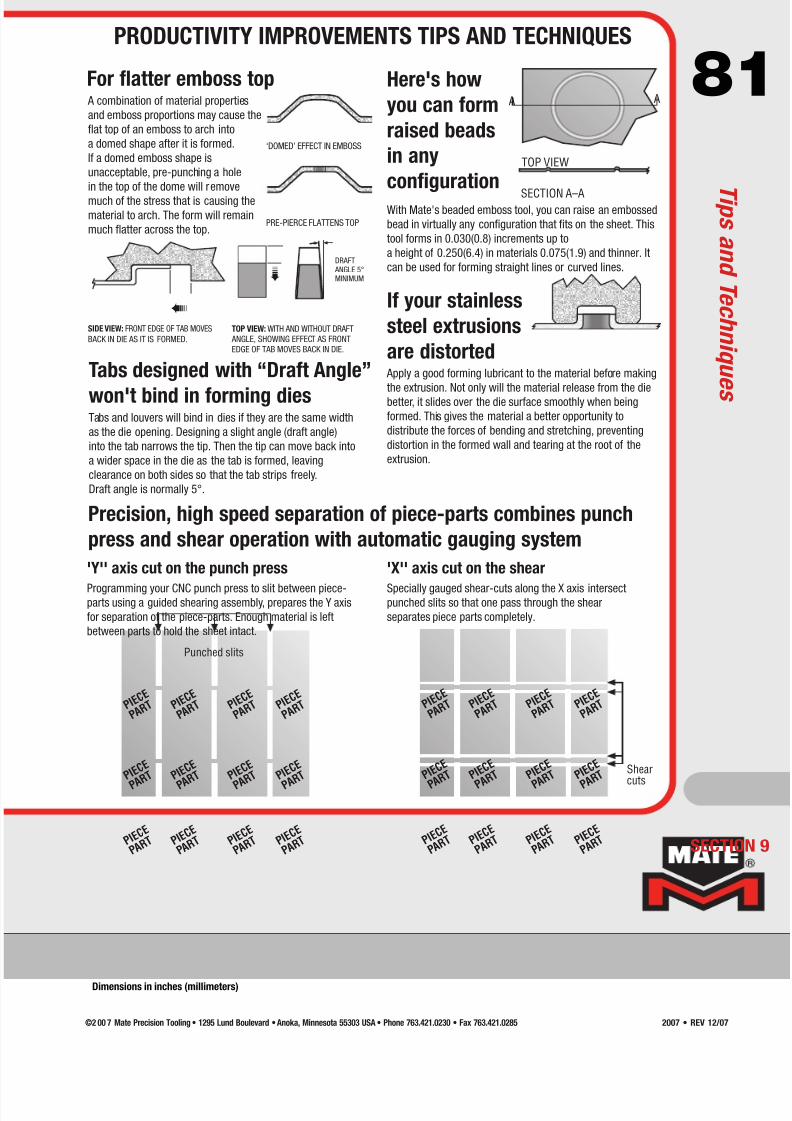
7/30/2019 Catalog Ultrafsdfsdf Tec
http://slidepdf.com/reader/full/catalog-ultrafsdfsdf-tec 81/96
81
«
«
Punched slits
P I E C E
P A R T P I E
C E
P A R T P I E
C E
P A R T P I E
C E
P A R T
P I E C E
P A R T P I E
C E
P A R T P I E
C E
P A R T P I E
C E
P A R T
P I E C E
P A R T P I E
C E
P A R T P I E
C E
P A R T P I E
C E
P A R T
Shear
cuts
P I E C E
P A R T P I E
C E
P A R T P I E
C E
P A R T P I E
C E
P A R T
P I E C E
P A
R T P I E C E
P A
R T P I E C E
P A
R T P I E C E
P A
R T
P I E C E
P A R T P I E
C E
P A R T P I E
C E
P A R T P I E
C E
P A R T
'Y'' axis cut on the punch press
Programming your CNC punch press to slit between piece-parts using a guided shearing assembly, prepares the Y axis
for separation of the piece-parts. Enough material is left
between parts to hold the sheet intact.
'X'' axis cut on the shear
Specially gauged shear-cuts along the X axis intersectpunched slits so that one pass through the shear
separates piece parts completely.
Precision, high speed separation of piece-parts combines punch
press and shear operation with automatic gauging system
A combination of material properties
and emboss proportions may cause the
flat top of an emboss to arch into
a domed shape after it is formed.
If a domed emboss shape is
unacceptable, pre-punching a hole
in the top of the dome will remove
much of the stress that is causing the
material to arch. The form will remain
much flatter across the top.
Tabs designed with “Draft Angle”
won't bind in forming diesTabs and louvers will bind in dies if they are the same width
as the die opening. Designing a slight angle (draft angle)
into the tab narrows the tip. Then the tip can move back into
a wider space in the die as the tab is formed, leaving
clearance on both sides so that the tab strips freely.
Draft angle is normally 5°.
With Mate's beaded emboss tool, you can raise an embossed
bead in virtually any configuration that fits on the sheet. This
tool forms in 0.030(0.8) increments up to
a height of 0.250(6.4) in materials 0.075(1.9) and thinner. It
can be used for forming straight lines or curved lines.
For flatter emboss top Here's how
you can form
raised beads
in any
configuration
If your stainless
steel extrusions
are distorted Apply a good forming lubricant to the material before making
the extrusion. Not only will the material release from the diebetter, it slides over the die surface smoothly when being
formed. This gives the material a better opportunity to
distribute the forces of bending and stretching, preventing
distortion in the formed wall and tearing at the root of the
extrusion.
SIDE VIEW: FRONT EDGE OF TAB MOVES
BACK IN DIE AS IT IS FORMED.
TOP VIEW: WITH AND WITHOUT DRAFT
ANGLE, SHOWING EFFECT AS FRONT
EDGE OF TAB MOVES BACK IN DIE.
PRE-PIERCE FLATTENS TOP
‘DOMED’ EFFECT IN EMBOSS
DRAFT ANGLE 5°MINIMUM
A A
TOP VIEW
SECTION A–A
SECTION 9
PRODUCTIVITY IMPROVEMENTS TIPS AND TECHNIQUES
T i p s a n d T e c h n i q u e s
Dimensions in inches (millimeters)
©2 00 7 Mate Precision Tooling • 1295 Lund Boulevard • Anoka, Minnesota 55303 USA • Phone 763.421.0230 • Fax 763.421.0285 2007 • REV 12/07

7/30/2019 Catalog Ultrafsdfsdf Tec
http://slidepdf.com/reader/full/catalog-ultrafsdfsdf-tec 82/96
82
75∞
45∞
60∞
TWO POPULAR CONFIGURATIONS…
90∞ 60∞
30∞
1st hit
2nd hit
77∞
59∞
98∞
77∞
59∞
Notch a variety of angles with
one set of 3-way corner
notching toolsHere's another candidate for an auto index station.
A three-way corner notching tool can cut any angle
larger than the smallest point by programming single
or multiple hits. 15° is the smallest angle available.
Consistent form
height requires stroke
controlConsistent, precise forming requires analysis
of punch press stroke dynamics. When theupper unit meets material, several tons of
force come into play. In applying this force,
the frame of the punch press tends to move
slightly in the opposite direction; to “yaw” in a manner that
increases shut height. As the punch pierces the material, punching
force reduces sharply and the frame springs back toward its
original position. This causes the upper unit to lunge deeper into
the lower unit.
The lunging motion typically occurs before the forming operation
has taken place. If the motion is not controlled, forming is
performed by spring back of the press frame and there is very
little control over accuracy of depth.
To counteract this process, Mate's Dyna-Form Stroke Control™positions the forming operation to become complete with upper
unit “bottomed” in the lower unit. Spring back does not affect the
depth. One piece part is exactly the same as the next. An
additional advantage of bottoming is to coin the forms, giving
them a crisp, well-defined appearance.
Dyna-Form Stroke Control is designed into all Mate special
assemblies which include forming of material.
Extra back taper on
punches reduces galling
If galling (build up on punch flank) is a problem, orderpunches with 2° total back taper.
Examine a Mate punch closely and you'll find that the
punch tip is largest at the cutting edge. It's because
we normally build in 1/4° total back taper (1/8° per
side). This minute change in size facilitates stripping:
material is much less likely to adhere to the punch.
Grind life is not affected. The reduction in diameter is
so small that the punch remains within normal
tolerances for both hole size and die clearance
throughout its life. Most likely you don't even notice
the back taper when examining your punches. But it's
there, working to make your punching more trouble
free.
If galling is especially troublesome, order a
combination of 2° total back taper (1° per side) on
the punch and 20% to 30% clearance for the die.
PUNCHING FORCECAUSES YAW
BACK TAPERIN THIS AREA
PUNCH PRESS AT REST
Insideradius
Outsideradius
With this tool, you do not have to stop your machine to
remove the slug for an oversize opening, or the blank if
saving the slug. Small, precise tabs keep slugs and
blanks intact while being punched, yet permit them to
break away from each other easily off the machine. The
precise tab is created by leaving a 0.016(0.4) gap
between hits.
The tool's large radii result in slugs or blanks with
smoother edges produced with far fewer hits than using
an ordinary radius punch for nibbling holes. One tool
punches slugs or blanks of any size practical for its
configuration with smoothest edges occurring when
radius punched and tool radius coincide.
This tool is for use in presses with tool rotation. Inside
radius must be larger than outside radius. Programming
requirements are enclosed with parts when shipped.
I/O radius tool cuts both insideand outside radii
ECTION 9
T i p s a n d T e c h n i q u e s
PRODUCTIVITY IMPROVEMENTS TIPS AND TECHNIQUES
Dimensions in inches (millimeters)
©2 00 7 Mate Precision Tooling • 1295 Lund Boulevard • Anoka, Minnesota 55303 USA • Phone 763.421.0230 • Fax 763.421.02852007 • REV 12/07

7/30/2019 Catalog Ultrafsdfsdf Tec
http://slidepdf.com/reader/full/catalog-ultrafsdfsdf-tec 83/96
83MATERIAL
1.004(25.5)DIE
DIAMETER
.967(24.6)PUNCH
DIAMETER
DIE
FIRSTHIT
.187(4.7)
MATERIAL
THICKNESS
MATERIAL
1.004(25.5)DIE
DIAMETER
DIE
SECONDHIT
1.000(25.4)PUNCH
DIAMETER
A BMATERIAL
TOOL
MATERIAL
TOOL
Shaving makes straight-walled
holes without drillingWhen you need a smooth, straight-walled hole for a shaft
bearing or other use, shaving can save the time and trouble of
performing a second operation on another machine. To do this,
you need to punch the hole twice. First, use a punch with a
punch-to-die Total Clearance equal to 20% material thickness.
Second, use a larger punch exactly the same size as the finished
hole. The die(s) used for both punches should be 0.004(0.10)
larger than the second punch.
The second hit will shave the sides of the hole, removing most of
the rollover and fracture effects caused in the first step, and
enlarge the burnished area. This operation works best on mild
steel and other materials ductile enough to shave.
An easy way to order tools for shaving is to use the finished holesize as a reference. Order PUNCH #2 to the finished hole size,
the DIE(S) to the same size as punch #2 + 0.004(0.10) Total
Clearance, and for PUNCH #1 subtract 20% material thickness
from the die size including clearance.
“Clearance corners” in
dies control corner burrsWhy put a radius in the corners of rectangular and square dies
with clearance greater than 0.020(0.5)? Because it keeps
clearance uniform around the corner of the punch.
If the die is sharp cornered too, then distance between punch
and die corners would be greater than side clearance, resultingin larger burrs. To get clearance corners always order “punch
size plus clearance”
[Ex. 1.000 + 0.037(25.4+0.9)].
Start continuous
louvers in
the centerContinuous louver tools are now
designed to produce smooth-
edged, level-topped louvers when
recommended procedures are
followed. Start in the center andform to one side and then the
other in 0.030(0.8) increments.
If needed, complete the process
by rehitting the center for
ultimate flatness.
Bridge hitting reduces tool wearBy alternating hits when performing shearing/slitting
operations, forces upon the tool remain balanced from side to
side and end to end. As a result, the punch operates square to
the material and die. Over time you will notice a difference in
the reduced frequency of sharpening and generally longer tool
service. This practice is called “bridge” hitting because the full
hits leave a “bridge” of material between them that is removed
by the bridge hits.
Sharpened tool edges stay sharp
longer if edges are dressedThe microscopic irregularities in workpieces and tools attack
each other with each impact. Protrusions and sharp corners
get flattened and knocked off. With very sharp tool edges (A),
flakes in various microscopic sizes are knocked off as the tool
wears. Each flake leaves a rough surface vulnerable to
additional flaking. For this reason, we recommend lightly
dressing the edge of freshly sharpened punches (B) with an
oil stone (India Oil Stone STO29807). This removes the corner,which is most vulnerable to breaking off. Although the radius
is tiny, it strengthens the tool edge by distributing stresses
which cause flaking. With a radius of just 0.001-0.002(0.03-
0.05), the tool can still be considered very sharp, and it stays
that way longer. This small radius is applied with only one
light pass of the stone per edge. You can't see the radius, but
it's there!
More holes per hit
save time,
cut costsMate cluster punches can increase the number of holes per
hit by several times. Many different punch designs and cluster
areas are available to provide a wide variety
of punching choices.
DIE
UNIFORMCLEARANCE
PUNCH
SECTION 9
BEGIN AT CENTER
WORK TO SIDE IN .030(0.8) INCREMENTS
RETURN TO CENTER AND WORK OTHER SIDE
RETURN FOR CENTER HIT IF NECESSARY
PRODUCTIVITY IMPROVEMENTS TIPS AND TECHNIQUES
T i p s a n d T e c h n i q u e s
Dimensions in inches (millimeters)
©2 00 7 Mate Precision Tooling • 1295 Lund Boulevard • Anoka, Minnesota 55303 USA • Phone 763.421.0230 • Fax 763.421.0285 2007 • REV 12/07

7/30/2019 Catalog Ultrafsdfsdf Tec
http://slidepdf.com/reader/full/catalog-ultrafsdfsdf-tec 84/96
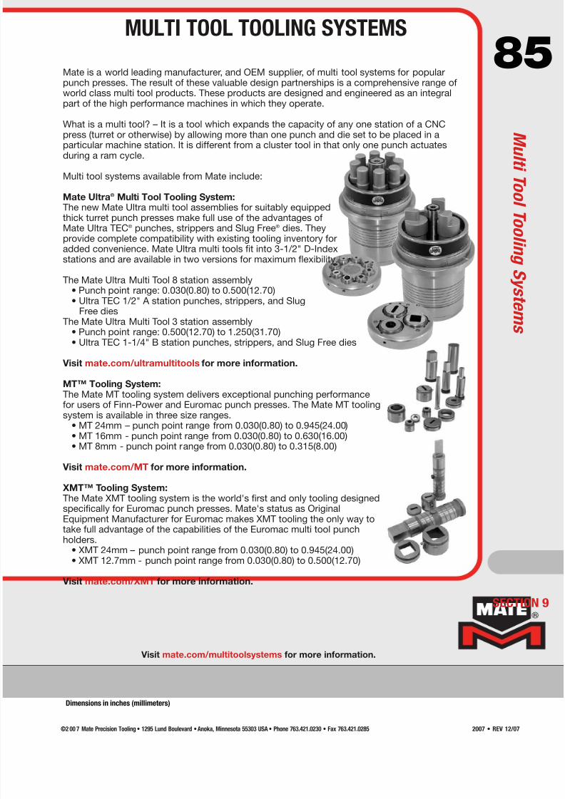
7/30/2019 Catalog Ultrafsdfsdf Tec
http://slidepdf.com/reader/full/catalog-ultrafsdfsdf-tec 85/96
85Mate is a world leading manufacturer, and OEM supplier, of multi tool systems for popularpunch presses. The result of these valuable design partnerships is a comprehensive range ofworld class multi tool products. These products are designed and engineered as an integralpart of the high performance machines in which they operate.
What is a multi tool? – It is a tool which expands the capacity of any one station of a CNCpress (turret or otherwise) by allowing more than one punch and die set to be placed in aparticular machine station. It is different from a cluster tool in that only one punch actuatesduring a ram cycle.
Multi tool systems available from Mate include:
Mate Ultra® Multi Tool Tooling System:The new Mate Ultra multi tool assemblies for suitably equippedthick turret punch presses make full use of the advantages ofMate Ultra TEC® punches, strippers and Slug Free® dies. Theyprovide complete compatibility with existing tooling inventory foradded convenience. Mate Ultra multi tools fit into 3-1/2" D-Indexstations and are available in two versions for maximum flexibility.
The Mate Ultra Multi Tool 8 station assembly• Punch point range: 0.030(0.80) to 0.500(12.70)• Ultra TEC 1/2" A station punches, strippers, and Slug
Free diesThe Mate Ultra Multi Tool 3 station assembly
• Punch point range: 0.500(12.70) to 1.250(31.70)• Ultra TEC 1-1/4" B station punches, strippers, and Slug Free dies
Visit mate.com/ultramultitools for more information.
MT™ Tooling System:The Mate MT tooling system delivers exceptional punching performancefor users of Finn-Power and Euromac punch presses. The Mate MT tooling
system is available in three size ranges.• MT 24mm – punch point range from 0.030(0.80) to 0.945(24.00)• MT 16mm - punch point range from 0.030(0.80) to 0.630(16.00)• MT 8mm - punch point range from 0.030(0.80) to 0.315(8.00)
Visit mate.com/MT for more information.
XMT™ Tooling System:The Mate XMT tooling system is the world's first and only tooling designedspecifically for Euromac punch presses. Mate's status as OriginalEquipment Manufacturer for Euromac makes XMT tooling the only way totake full advantage of the capabilities of the Euromac multi tool punchholders.
• XMT 24mm – punch point range from 0.030(0.80) to 0.945(24.00)
• XMT 12.7mm - punch point range from 0.030(0.80) to 0.500(12.70)
Visit mate.com/XMT for more information.
Visit mate.com/multitoolsystems for more information.
SECTION 9
MULTI TOOL TOOLING SYSTEMS
M u l t i T o o l T o o l i n g S y s t e m s
Dimensions in inches (millimeters)
©2 00 7 Mate Precision Tooling • 1295 Lund Boulevard • Anoka, Minnesota 55303 USA • Phone 763.421.0230 • Fax 763.421.0285 2007 • REV 12/07

7/30/2019 Catalog Ultrafsdfsdf Tec
http://slidepdf.com/reader/full/catalog-ultrafsdfsdf-tec 86/96
86Machines equipped with tool lubrication systems introduce a
lubrication fluid (oil, or an oil/air mixture) into the top of the tooling
system. This diagram shows the method of transporting this fluid
throughout the Ultra® tooling system in the 1/2" A (not show) and
1-1/4" B station (as shown) system.
The lubrication fluid – is introduced at the top of the tool
by the machine mechanism.
It travels through the center of the assembly.
It flows through four fluid transportation holes in the punch.
Two holes have been shown here. The four holes are at 90
degrees from each other.
The lubrication fluid reaches the interior wall of the Ultra guide.
The lubrication fluid also reaches the exterior of the guide.
There are internal keyways (Three for 1/2 A, Five for 1-1/4
B-Station) in the Ultra guide for punch angle settings.
One keyway will be obstructed with the key of the punch.
The lubrication fluid moves through the remaining four
unobstructed keyways to the stripper pooling area.
The punch spiral grooves evenly distribute the lubrication fluid
around the entire interior of the guide.
The exterior spiral grooves evenly distribute the lubrication fluid
around the entire guide between the guide and the turret bore.
The exterior spiral grooves do not extend beyond the turret bore.
This keeps the lubrication on the contact surfaces and prevents
the fluid from draining onto the work surface.
Stripper pooling area.
For Ultra ABS® Only:
Fluid is expelled through the small reliefs in the stripper
next to the punch.
Ultra ABS is licensed under U.S. Patent No. 4,977,804 and corresponding foreign patents
and patent applications, and authorized for use only on punch press machines
manufactured by, for, or under license from Amada Company, Ltd.
ECTION 9
U l t r a T o o l L u b r i c a t i o n S y s t e m
ULTRA® TOOL LUBRICATION SYSTEM
1/2" A AND 1-1/4" B STATION
©2 00 7 Mate Precision Tooling • 1295 Lund Boulevard • Anoka, Minnesota 55303 USA • Phone 763.421.0230 • Fax 763.421.02852007 • REV 12/07

7/30/2019 Catalog Ultrafsdfsdf Tec
http://slidepdf.com/reader/full/catalog-ultrafsdfsdf-tec 87/96
87Machines equipped with tool lubrication
systems introduce a lubrication fluid (oil,
or an oil/air mixture) into the top of a tooling
system. This diagram shows the method of
transporting this mixture throughout the Ultra®
tooling system in the 2" C, 3-1/2" D (as shown),and the 4-1/2" E station system.
The lubrication fluid is introduced at the top
of the tool by the machine mechanism.
It travels through the center of the assembly.
It flows through three fluid transportation
holes. Two holes have been shown here.
The three holes are at 120 degrees from
each other.
The lubrication fluid reaches the interior wall of
the guide as it flows through three channels.
The lubrication fluid also reaches the exterior
of the guide.
The interior spiral grooves evenly distribute
the lubrication fluid around the entire punch
between the punch and the guide.
The exterior spiral grooves evenly distribute
the lubrication fluid around the entire guide
between the guide and the turret bore.
The exterior spiral grooves do not extend
beyond the turret bore. This keeps the
lubrication on the contact surfaces and
prevents the fluid from draining onto the work
surface.
There are three vertical interior guide grooves
that transport the fluid to the stripper pooling
area.
Stripper pooling area.
For Ultra ABS® Only:
Fluid is expelled through the small reliefs
in the stripper next to the punch.
Ultra ABS is licensed under U.S. Patent No. 4,977,804 and corresponding foreign patents
and patent applications, and authorized for use only on punch press machines
manufactured by, for, or under license from Amada Company, Ltd.
SECTION 9
ULTRA® TOOL LUBRICATION SYSTEM
2" C, 3-1/2" D, AND 4-1/2" E STATION
U l t r a T o o l L u b r i c a t i o n S y s t e m
©2 00 7 Mate Precision Tooling • 1295 Lund Boulevard • Anoka, Minnesota 55303 USA • Phone 763.421.0230 • Fax 763.421.0285 2007 • REV 12/07
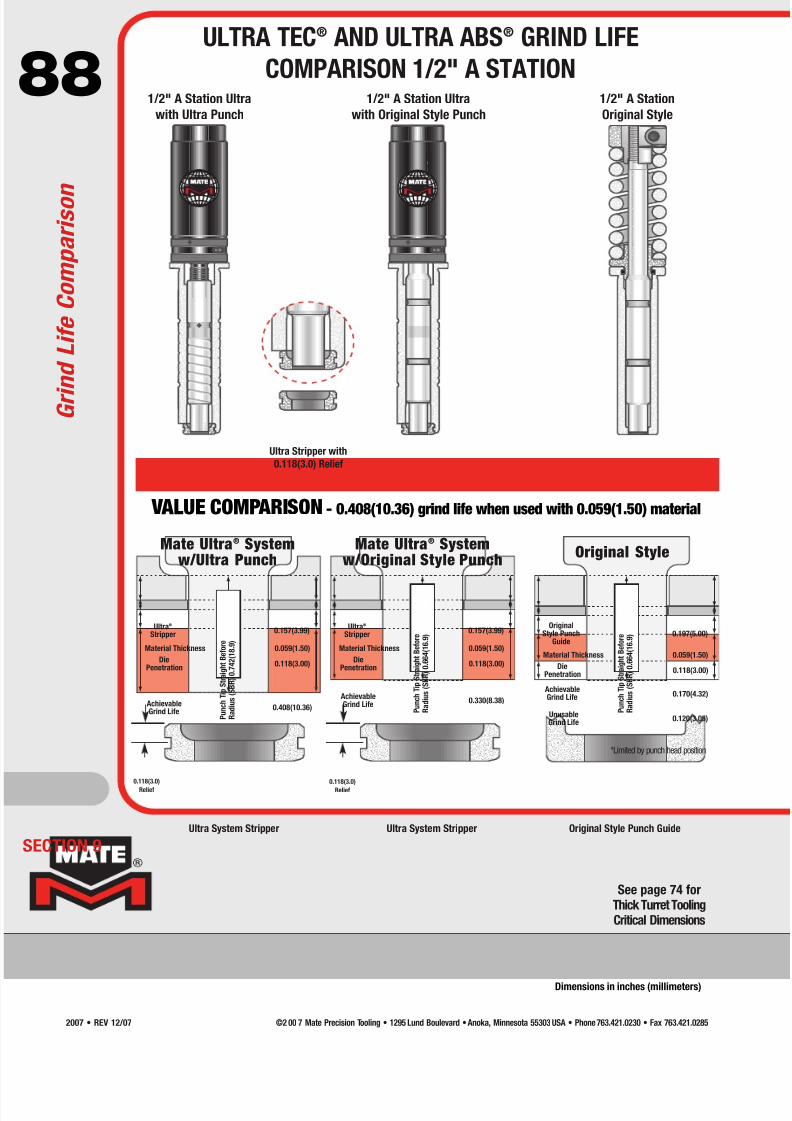
7/30/2019 Catalog Ultrafsdfsdf Tec
http://slidepdf.com/reader/full/catalog-ultrafsdfsdf-tec 88/96
88
Ultra System Stripper Ultra System Stripper Original Style Punch Guide
VALUE COMPARISON - 0.408(10.36) grind life when used with 0.059(1.50) material
®
1/2" A Station Ultra
with Ultra Punch
®
1/2" A Station Ultra
with Original Style Punch
Ultra Stripper with
0.118(3.0) Relief
1/2" A Station
Original Style
0.118(3.0)
Relief
0.118(3.0)
Relief
Mate Ultra® Systemw/Ultra Punch
Mate Ultra® Systemw/Original Style Punch
Original Style
ECTION 9
P u n c h
T i p
S t r a i g h t B e f o r e
R a d i u s
( S B R ) 0 . 7 4 2 ( 1 8 . 9 )
0.157(3.99)
0.059(1.50)
0.118(3.00)
0.408(10.36)
Ultra®
Stripper
Material Thickness
DiePenetration
AchievableGrind Life P
u n c h
T i p
S t r a i g h t B e f o r e
R a d i u s
( S B R ) 0 . 6 6 4 ( 1 6 . 9 )
0.157(3.99)
0.059(1.50)
0.118(3.00)
0.330(8.38)
Ultra®
Stripper
Material Thickness
DiePenetration
AchievableGrind Life
See page 74 forThick Turret ToolingCritical Dimensions
G r i n d L i f e C o m p a r i s o n
ULTRA TEC® AND ULTRA ABS® GRIND LIFE
COMPARISON 1/2" A STATION
Dimensions in inches (millimeters)
P u n c h
T i p
S t r a i g h t B e f o r e
R a d i u s
( S B R ) 0 . 6 6 4 ( 1 6 . 9 ) 0.197(5.00)
0.059(1.50)
0.118(3.00)
0.170(4.32)
OriginalStyle Punch
Guide
Material Thickness
DiePenetration
AchievableGrind Life
0.120(3.05)UnusableGrind Life
*Limited by punch head position
©2 00 7 Mate Precision Tooling • 1295 Lund Boulevard • Anoka, Minnesota 55303 USA • Phone 763.421.0230 • Fax 763.421.02852007 • REV 12/07
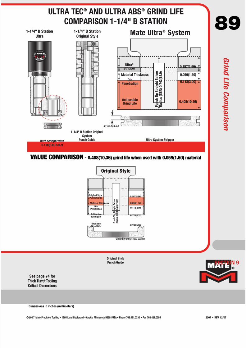
7/30/2019 Catalog Ultrafsdfsdf Tec
http://slidepdf.com/reader/full/catalog-ultrafsdfsdf-tec 89/96
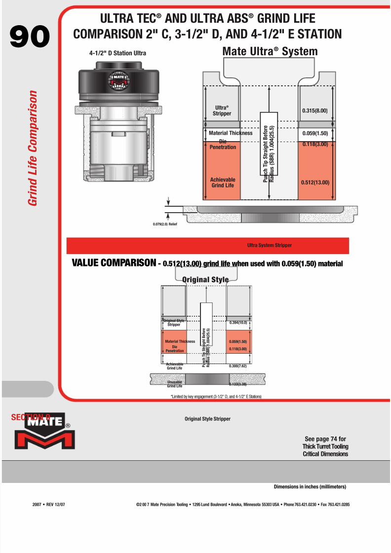
7/30/2019 Catalog Ultrafsdfsdf Tec
http://slidepdf.com/reader/full/catalog-ultrafsdfsdf-tec 90/96
90
®
Mate Ultra® System
Original Style Stripper
Ultra System Stripper
VALUE COMPARISON - 0.512(13.00) grind life when used with 0.059(1.50) material
Original Style
4-1/2" D Station Ultra
0.079(2.0) Relief
ECTION 9
*Limited by key engagement (3-1/2" D, and 4-1/2" E Stations)
P u n c h
T i p
S t r a i g h t B e f o r e
R a d i u s
( S B R ) 1 . 0 0 4 ( 2 5 . 5 )
0.315(8.00)
0.059(1.50)
0.118(3.00)
0.512(13.00)
Ultra®
Stripper
Material Thickness
DiePenetration
AchievableGrind Life
P u n c h
T i p
S t r a i g h t B e f o r e
R a d i u s
( S B R ) 1 . 0 0 4 ( 2 5 . 5 )
0.394(10.0)
0.059(1.50)
0.118(3.00)
0.300(7.62)
Original StyleStripper
Material Thickness
DiePenetration
Unusable
Grind Life
AchievableGrind Life
0.133(3.38)
See page 74 forThick Turret ToolingCritical Dimensions
G r i n d L i f e C o m p a r i s o n
ULTRA TEC® AND ULTRA ABS® GRIND LIFE
COMPARISON 2" C, 3-1/2" D, AND 4-1/2" E STATION
Dimensions in inches (millimeters)
©2 00 7 Mate Precision Tooling • 1295 Lund Boulevard • Anoka, Minnesota 55303 USA • Phone 763.421.0230 • Fax 763.421.02852007 • REV 12/07

7/30/2019 Catalog Ultrafsdfsdf Tec
http://slidepdf.com/reader/full/catalog-ultrafsdfsdf-tec 91/96
91
SECTION 9
Use this table to determine the compatibility of Mate punches, strippers, and dies with popular tooling systems.
● Indicates punch, stripper, or die is compatible with the corresponding tool system
Tool Style
M a t e P a r t N u m b e r
U l t r a T E C
®
U l t r a X T ™
U l t r a A B S
®
M a t e O r i g
i n a l
H P ™
H P ™ WL S ®
H P ™ A B S
Wi l s o n I n c h S t y l e
A m a d a S t a n d a r d
A m a d a A B S
A m a d a Z - S t a n d a r d
A m a d a Z -A B S
A m a d a N E X S t a n d a r d
A m a d a N E X A B S
A m a d a A l p h a
1/2" A Station
Punch
Ultra TEC® Punch PAUA ● ● ●
Metric (Original) Punch PAAA ● ● ● ● ● ●
Ultra ABS® Punch PAYA ● ●
Stripper
Ultra TEC® S6KA ● ● ●
Original Style S6AA ● ● ● ●
Ultra ABS® S6YA ● ●
Die Slug Free® Die D0AA ● ● ● ● ● ● ● ● ● ● ● ● ● ● ●
1-1/4" B Station
Punch
Ultra TEC® Punch PAUB ● ● ●1 ●
Metric (Original) Punch PAAB ● ● ● ● ● ●
Ultra ABS® Punch PAYB ● ●
Inch Style PAJB ● ● ● ●
Stripper
Ultra TEC® S6KB ● ● ●
Original Style S6AB ● ● ● ●
Ultra ABS® S6YB ● ●
Die Slug Free® Die D0AB ● ● ● ● ● ● ● ● ● ● ● ● ● ● ●
2" C, 3-1/2" D, and 4-1/2" E Stations
Punch
Original Style (M12 bolt) PAA ● ● ● ● ● ●2 ●2
Inch Style (1/2-13 bolt) PAJ ●
MXC™ PXC ● ●
Stripper
Ultra TEC® S6K ●
Original Style S6A ● ● ● ●3 ●3
Ultra ABS® S6Y ●
MXC™ SXC ● ●
Die Slug Free® Die D0A ● ● ● ● ● ● ● ● ● ● ● ● ●
Notes:
1. Round Ultra TEC punches are not compatible with HP guides.
2. Requires the optional M12 bolt to be installed into the guide.
3. Requires use of optional Original style strippers.
THICK TURRET COMPATIBILITY CHART
T o o l i n g S y s t e m C
o m p a t i b i l i t y
©2 00 7 Mate Precision Tooling • 1295 Lund Boulevard • Anoka, Minnesota 55303 USA • Phone 763.421.0230 • Fax 763.421.0285 2007 • REV 12/07
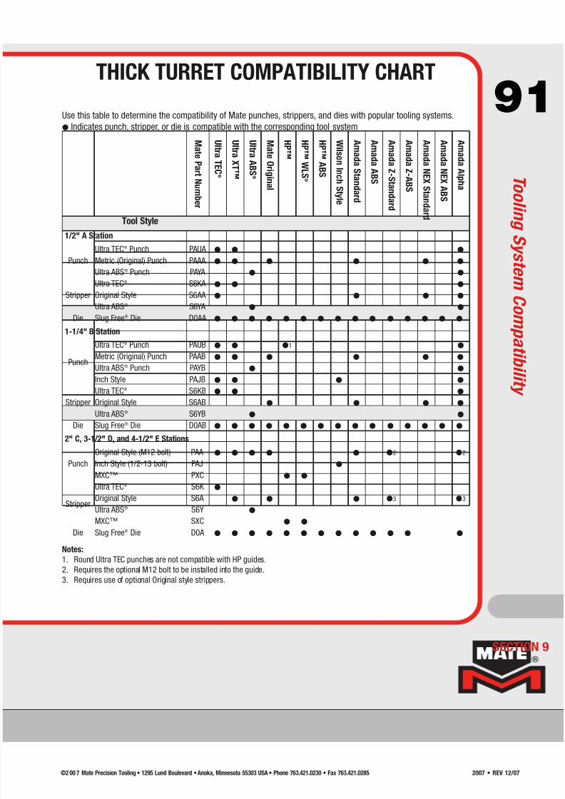
7/30/2019 Catalog Ultrafsdfsdf Tec
http://slidepdf.com/reader/full/catalog-ultrafsdfsdf-tec 92/96
92
Nitriding is an optional heat treatment feature for high speed steel (HSS) punches. It is a
surface treatment, which becomes an integral component of the structure of the material itself.
Nitrided punches are recommended for punching abrasive materials such as fiberglass or
materials that cause galling such as stainless steel, galvanized steel, and aluminum. It is also
recommended for high speed nibbling applications. It is not recommended for punches smaller
than 0.158(4.01) in diameter or width, for material thicker than 0.250(6.35), or where significant
punch deflection may occur.
Maxima® Coating
Nitride Treatment
ShapeMinimum tool widths suitable
for Maxima coating
Minimum tool widths suitable
for Nitride treatment
Round Minimum diameter is 0.098(2.50) Minimum diameter = 0.158(4.01)
RectangleIf length is >0.250(6.35) the minimum width is 0.060(1.50)
If length is <0.250(6.35) the minimum width is 0.098(2.50)Minimum width = 0.158(4.01)
OvalIf length is >0.250(6.35) the minimum width is 0.060(1.50)
If length is <0.250(6.35) the minimum width is 0.098(2.50)
Minimum width = 0.158(4.01)
Square Minimum width is 0.098(2.50) Minimum width = 0.158(4.01)
Others Consult a Mate application specialist Consult a Mate application specialist
ECTION 9
M a x i m a ® C o a t i n g a n d N i t r i d e T r e a t m e n t
MAXIMA® COATING AND
NITRIDE TREATMENT
Maxima is a premium tool steel coating that has been specially formulated for turret punch
press tooling applications. Maxima is a multilayer Zirconium Titanium Nitride (ZrTiN) coating
that is hard, wear resistant, and lubricious. It acts as a barrier between the punch and the sheet
metal being punched and, because of its exceptional lubricity, greatly improves stripping.
Why is Maxima better? Maxima is applied to the precision ground surface of Mate’s premium
tool steel punches. Since Maxima is an extremely hard, wear resistant, slippery material which
reduces the friction that occurs during the stripping portion of the punching cycle, it is
particularly good for abrasive tooling applications. Less friction means less heat build up, less
galling and longer tool life.
Results! In real life tests around the world, Maxima has increased tool life by a factor of 2
times, and even 10 times, and the tools are still in production.
©2 00 7 Mate Precision Tooling • 1295 Lund Boulevard • Anoka, Minnesota 55303 USA • Phone 763.421.0230 • Fax 763.421.02852007 • REV 12/07
7/30/2019 Catalog Ultrafsdfsdf Tec
http://slidepdf.com/reader/full/catalog-ultrafsdfsdf-tec 93/96
93M4PM™ is a high speed, particle metallurgy tool steel
designed for use in high performance tooling systems.
A combination of the chemical composition of M4, the
particle metallurgy manufacturing process, and the triple
temper heat treatment process, produces M4PM: the
world’s finest tool steel for use in punching tools.
M4PM is a very homogeneous, high quality tool steel
which has many advantages when compared to
alternative tool steels commonly available. These
advantages include:
Superior Wear Resistance – 100% better wearing,
M4PM offers superior resistance to adhesive- and
abrasive-wear to maximize the interval between regrinds.
• More uniform distribution of smaller carbides—results in
improved ductility (adhesive-wear) while still providingabrasive-wear resistant carbides over the entire surface
of the material.
• 100% more Vanadium carbides—harder wearing for
greater resistance to abrasive-wear.
• Increased Tungsten carbides—harder wearing and offer
better red hardness; increased resistance to high
temperatures which may anneal or damage the material.
• Higher hardenability—increased alloy content results in
higher effective hardness for better wear resistance.
Increased Toughness – the molecular structure of M4PM
is 50% tougher than conventional tool steels in impact
strength tests.
• Triple temper heat treatment process—ensures full
conversion of the material matrix. Results in fully
tempered martensite and reduced internal stress,
together with better dimensional stability.
• More uniform distribution of smaller carbides—offsets
the effects of increased alloy content. Results in a more
“interlocked” material matrix for significantly reduced
tool breakage and edge chipping. See micrograph.
Better Value – customer trials have shown that tools
manufactured in M4PM last 100% longer betweenregrinds than tools manufactured using conventional High
Speed Steel. By increasing the interval between regrinds,
the tooling lasts longer and punches many more holes
before needing to be replaced.
Toughness* Relative Wear Res istance**
250
200
150
100
50
0
H i g h C h r o m e
( D 2 )
H S S ( M 2 )
M 4 P M
T o u g h n e s s ( f t - L b s ) / W e a r I n d e x
M4PM™ Conventional
Tool Steel
Micrograph shows that the particle
metallurgy process produces a very
homogeneous, high quality tool
steel with superior wear resistance,
toughness and dimensional stability.
*Toughness: Charpy C-Notch impact strength test.
**Relative Wear Resistance: 10x Cross cylinder adhesive wear test.
Based upon steel manufacturers data.
International Material Standards
D2 M2 M4PM
JIS SKD 11 SKH 51 SKH 54
WNr 1.2379 1.3343 none
DIN X155 CrVMo 12-1 HS 6-5-2 none
M4PM Chemical Composition
Carbon 1.42%
Chromium 4.00%
Vanadium 4.00%
Tungsten 5.50%
Molybdenum 5.25%
SECTION 9
M4PM™ TOOL STEEL
M4 P M™T o o l S t e
e l
©2 00 7 Mate Precision Tooling • 1295 Lund Boulevard • Anoka, Minnesota 55303 USA • Phone 763.421.0230 • Fax 763.421.0285 2007 • REV 12/07

7/30/2019 Catalog Ultrafsdfsdf Tec
http://slidepdf.com/reader/full/catalog-ultrafsdfsdf-tec 94/96
94
ECTION 9
A d d - O n s
ADD-ONS
GeneralRadius Corners
Non-Standard Straight Before Radius (SBR) DimensionSpecial Angle SettingsOptional Shear (Limited Options)
Small Diameter Round ToolsDiameter 0.031(0.79) to 0.061(1.55)
Diameter 0.062(1.56) to 0.092(2.34)
Narrow Width Shaped Tools
Widths under 0.079(2.00)
Station Jumper
1-1/4" B Station - if diagonal dimension is <0.500(12.70)2" C Station - if diagonal dimension is <1.250(31.70)3-1/2" D Station - if diagonal dimension is <2.000(50.80)4-1/2" E Station - if diagonal dimension is <3.500(88.90)
6" F Station - if diagonal dimension is <4.500(114.30)
Maxima® Coating - See Page 92
1/2" A Station1-1/4" B Station2" C Station
3-1/2" D Station4-1/2" E Station6" F Station
Slitting Punch Insert
Nitride Treatment - See Page 92
1/2" A Station1-1/4" B Station
2" C Station3-1/2" D Station
4-1/2" E Station6" F StationSlitting Punch Insert
Slug Free Light™ Die Geometry - See Page 131/2" A Station
1-1/4" B Station2" C Station3-1/2" D Station
4-1/2" E Station
1/2" A Station1-1/4" B Station2" C Station3-1/2" D Station
4-1/2" E Station
Contact your Mate
representative for
pricing information.
©2 00 7 Mate Precision Tooling • 1295 Lund Boulevard • Anoka, Minnesota 55303 USA • Phone 763.421.0230 • Fax 763.421.02852007 • REV 12/07
7/30/2019 Catalog Ultrafsdfsdf Tec
http://slidepdf.com/reader/full/catalog-ultrafsdfsdf-tec 95/96
95
SECTION 9
Mate Ultra TEC®
1/2" A Canister and guide with Ultra punch, stripper, and Slug Free® die
1-1/4" B Canister and guide with Ultra punch, stripper, and Slug Free® die
2" C Original punch, Ultra stripper, Slug Free® die
3-1/2" D Original punch, Ultra stripper, Slug Free®
die4-1/2" E Original punch, Ultra stripper, Slug Free® die
See pages 10-12 for complete ordering information
Ultra TEC® Fully Guided
1-1/4" B Canister and guide with Ultra punch, guided stripper, and Slug Free® die
2" C Original punch, guided stripper, Slug Free® die
3-1/2" D Original punch, guided stripper, Slug Free® die
4-1/2" E Original punch, guided stripper, Slug Free® die
See pages 16-17 for complete ordering information
Ultra TEC® Fully Guided Clamp Clearing
3-1/2" D Punch insert, clamp clearing stripper and clamp clearing Slug Free® die
4-1/2" E Punch insert, clamp clearing stripper and clamp clearing Slug Free® die
See page 19 for complete ordering information
Ultra XT™
1/2" A Canister and guide with Ultra punch, Ultra stripper, and Slug Free® die
1-1/4" B Canister and guide with Ultra punch, Ultra stripper, and Slug Free® die
2" C Original punch, original stripper, and Slug Free® die
3-1/2" D Original punch, original stripper, and Slug Free® die
4-1/2" E Original punch, original stripper, and Slug Free® die
See pages 24-26 for complete ordering information
Original Style Thick Turret
1/2" A Complete assembly with Slug Free® die
1-1/4" B Complete assembly with Slug Free® die
2" C Original punch, original stripper, and Slug Free® die
3-1/2" D Original punch, original stripper, and Slug Free® die
4-1/2" E Original punch, original stripper, and Slug Free® die
6” F Original punch, original stripper, and Slug Free® die
See pages 33-37 for complete ordering information
MXC™ Tooling System
2" C Punch, stripper, and Slug Free® die
3-1/2" D Punch, stripper, and Slug Free® die4-1/2" E Punch, stripper, and Slug Free® die
See page 45 for complete ordering information
Station Tool Style
Round Rectangle Oval Squ are Single-D Dou ble-D
Quad-D TriangleHexagon Octagon Diamond
STANDARD SHAPES
THICK TURRET TOOLING SYSTEMQUICK REFERENCE PRICE GUIDE
T h i c k T u r r e t Q u i c k R
e f e r e n c e P r i c e G u i d e
C on t
a c t y o ur M a t er e pr e s en t a t
i v e
f or pr i ci n gi nf or m a t i on.
©2 00 7 Mate Precision Tooling • 1295 Lund Boulevard • Anoka, Minnesota 55303 USA • Phone 763.421.0230 • Fax 763.421.0285 2007 • REV 12/07

7/30/2019 Catalog Ultrafsdfsdf Tec
http://slidepdf.com/reader/full/catalog-ultrafsdfsdf-tec 96/96
mate.com