catalogo 3arm def
TRANSCRIPT

Customer CommittmentTo work hard everyday to be regarded in the metal
working marketplace as a supplier that is friendly, helpful and easy to do business with - EVERYDAY, EVERYTIME.
To offer innovative high quality solutions at a competitive price.
To be receptive & proactive in identifying solutions for our customers needs & requirements.
© Tecnospiro Machine Tool S.L. Modifi cations reservedEdition: September 2014
Tecnospiro Machine Tool, S.L.
Tel. +34 93 8764359 Fax. +34 93 8767738PI. Pla dels Vinyats, B
08250 St.Joan de Vilatorrada Barcelona3ARM® www.3arm.net
www.3arm.net
1Catalogwww.3arm.net
Ergonomic Solutions
Quick Guide
Applications
Series 1
Series 2
Series 3
Series 4
Series 6 Telescopic
Accessories
3
7
8
10
12
16
18
20
Index3 Arm is a division of the Tecnospiro Machine
Tool Company located in Sant Joan de Vilatorrada a small village about 40 miles
west of Barcelona. They are a small family owned company that has been in business since the 60’s. They have a state of the art manufacturing facility and a dynamic engineering staff that has been very innovative in design and inventing new products. The 3Arm ergonomic arm is the strongest most dependable arm available in the world market place today. It can be used for assistance in assembly, deburring, off line machining, and all types of lifting operations. Where ever operator fatigue is concern for employee safety, productivity, or quality 3Arm has a solution.
SAFETY WARNING 3ARM products are engineered and manufactured with safety in mind. The heat treat specifi cations
exceed or meet all standards. All of the products manufactured by 3ARM are designed to perform without any undue safety issues when caution, common sense and proper safety practices are followed. The use of cutting tools and toolholders is safe when proper application and protection guidelines are observed. Even when these proper precautions are taken, it is possible that fragments of a cutting tool, cutting material, or holding device may be thrown at a very high rate of speed and have potential to cause severe bodily harm. It is imperative that general safety precautions and safety glasses be used at all times.
Tecnospiro Machine Tool, S.L.
Tel. +34 93 8764359 Fax. +34 93 8767738PI. Pla dels Vinyats, B08250 St.Joan de Vilatorrada Barcelona3ARM® www.3arm.net
23
3arm Notes

22 3
SERIES 1 SERIES 2 SERIES 3 SERIES 4 SERIES 6 (Telescopic)
Max. RADIUS mm/inches 1120/44” 860/34” 1730/68” 1460/58” 2190/86”
VERTICAL DISTANCEmm/inches
1070/42” 530/22” 1070/42” 1375/54” 670/26”
MAXIMUM WEIGHT Kg./lbs 10 / 22 6 / 13 35 / 77 24 / 53 20 / 44
LOCK ON BRAKES NO NO OPTIONAL OPTIONAL NO
Top or BOTTOM Mounted YES YES YES YES YES
3arm Details
Head members
J L M
N, Q R
A B C D
Tilting arm movement only
X: Turns 360º. Lockable in any position Z: Turns 90º right and left. Lockable in any position
Tilting arm movement only
X: Turns 90º. Lockable in any position Y: Turns 90º right & left.Z: Turns 360º. Lockable in any position. Height adjustable up to 175 mm.
Z: Turns 90º right & left.
Tilting arm movement only
N: from 0 up to 15 kg with Quick change X: Turns 360º. Lockable 4x90º. Z1:Turns 90º right & left. Z2: Turns 360º. Q: from 15 up to 30 kgX: Turns 360º. Lockable in any positionZ1: Turns 90º right & leftZ2: Turns 360º. Lockable in any position
X:Turns 360º, Z: Turns 90º right & left. Lockable in any position
X: Turns 360º. 64 Lockable positions Z1: Turns 90º left. 5 Lockable positions Z2: Turns 360º. 8 Lockable positions
X
T: from 0 up to 15 kg with Quick change X: Turns 360º. Lockable 4x90º Y: Turns 360º Z1: Turns 90º right & leftZ2: Turns 360º U: from 15 up to 30 kg X: Turns 360º. Lockable 4x90º Y: Turns 360º. Lockable in any position Z1: Turns 90º right & left Z2: Turns 360º
X1: Turns 360º. Lockable each 45º X2: Turns 360º Y: Turns 360º Z1: Turns 90º right & left. Z2: Turns 360º
E F G, H
I
X: Turns 360º. Lockable in any position Z: Turns 90º right & left. Lockable in any position
X: Turns 360º. Lockable in any position Z: Turns 90º right & left. Lockable in any position
G: from 0 up to 15 kg/33 lbs with Quick Change
X1: Turns 360º. Lockable each 45º X2: Turns 360º. Y: Turns 360º. Z1: Turns 90 right & left. Z2: Turns 360º. Non lockable
H: from 15 kg/33 lbs up to 30 kg/66 lbs. NO Quick Change X: turns 360º. Lockable in any position Y: Turns 360º. Lockable in any position Z1: Turns 90º right & left Z2: Turns 360º
Z: Turns 90º right & left. Lockable in any position
Quick Guide
T,U
4
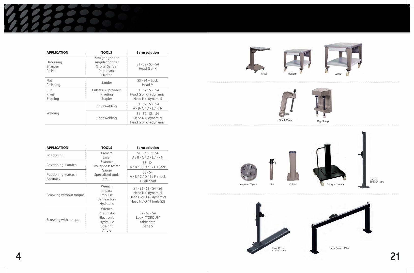
APPLICATION TOOLS 3arm solution
PositioningCamera
LaserScanner
Roughness testerGauge
Specialized toolsetc…
S1- S2 - S3 - S4 A / B / C / D / E / F / N
Positioning + attachS3 - S4
A / B / C / D / E / F + lock
Positioning + attachAccuracy
S3 - S4A / B / C / D / E / F + lock
+ Ball head
Screwing without torque
WrenchImpactImpulse
Bar reactionHydraulic
S1 - S2 - S3 - S4 - S6Head N (- dynamic)
Head G or X (+ dynamic)Head H / Q / T (only S3)
Screwing with torque
WrenchPneumaticElectronicHydraulicStraightAngle
S2 - S3 - S4Look “TORQUE”
table datapage 5
APPLICATION TOOLS 3arm solution
Deburring SharpenPolish
Straight grinderAngular grinderOrbital Sander
PneumaticElectric
S1 - S2 - S3 - S4 Head G or X
FlatPolishing
SanderS3 - S4 + Lock.
Head M
CutRivetStapling
Cutters & SpreadersRivetingStapler
S1 - S2 - S3 - S4Head G or X (+dynamic)
Head N (- dynamic)
Welding
Stud WeldingS1 - S2 - S3 - S4
A / B/ C / D / E / F/ N
Spot WeldingS1 - S2 - S3 - S4
Head N (- dynamic)Head G or X (+dynamic)
21
Small Medium Large
Small Clamp
Magnetic Support Column
Trolley with Column
2000S Column Lifter
Linear Guide + Pillar
Lifter
Big Clamp
Trolley with Column
Floor Rail + Column Lifter
Trolley + Column
20
Accessories
CALL FOR AN ENGINEERED SOLUTION
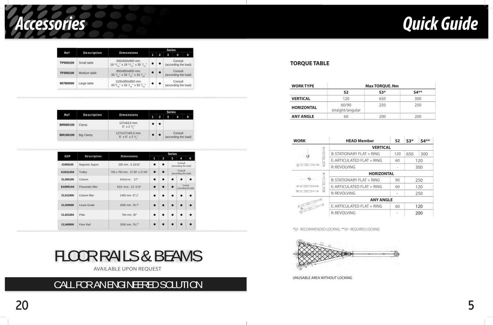
Ref Description DimensionsSeries
1 2 3 4 6
TP000100 Small table 500x500x900 mm.19 11/16” x 19 11/16” x 35 7/16”
Consult(according the load)
TF000100 Medium table 850x850x850 mm.33 7/16” x 33 7/16” x 33 7/16”
Consult(according the load)
907B0000 Large table 1100x850x850 mm.43 5/16” x 33 7/16” x 33 7/16”
Consult(according the load)
Ref Description DimensionsSeries
1 2 3 4 6
BR000100 Clamp 127x63,5 mm.5” x 2 1/2”
BR100100 Big Clamp 127x127x65,5 mm.5” x 5” x 2 1/2”
Consult(according the load)
EDP Description DimensionsSeries
1 2 3 4 6
IC000100 Magnetic Suport 250 mm. 9 13/16” Consult (according the load)
KA011X04 Trolley 700 x 700 mm. 27,55” x 27,55” Consult (according the load)
CL000100 Column 940mm. 37”
EA0001A0 Pneumatic lifter 550 mm. 21 5/8” Consult (according the load)
CL013300 Column lifter 1450 mm. 57,1”
CL020000 Linear Guide 2000 mm. 78,7”
CL021504 Pillar 764 mm. 30”
CL040000 Floor Rail 2000 mm. 78,7”
FLOOR RAILS & BEAMSAVAILABLE UPON REQUEST
5
Quick Guide
WORK HEAD Member S2 S3* S4**VERTICAL
B: STATIONARY FLAT + RING 120 650 300
E: ARTICULATED FLAT + RING 60 120
R: REVOLVING - 300
HORIZONTAL
B: STATIONARY FLAT + RING 90 250
E: ARTICULATED FLAT + RING 60 120
R: REVOLVING - 250
ANY ANGLE
E: ARTICULATED FLAT + RING 60 120
R: REVOLVING - 200
WORK TYPE Max TORQUE. Nm
S2 S3* S4**
VERTICAL 120 650 300
HORIZONTAL60/90
straight/angular250 250
ANY ANGLE 60 200 200
*S3 - RECOMMENDED LOCKING, **S4 - REQUIRED LOCKING
UNUSABLE AREA WITHOUT LOCKING
TORQUE TABLE

6
Quick Guide
BIG CLAMP
TABLE
FLOOR RAIL + LIFTER 2000
TROLLEY + COLUMN + PNEUMATIC LIFTER
TOLLEY + LIFTER 2000
BEAM + PILLARS
Accessories
19
Top & Bottom Mount
Damper Weight Range
Head Type
N6 T6
Load Range Kg Min Min
0 11
2 13
3 15
4 18
6 20SER
IES
6
TELE
SCO
PIC
B
OT
TOM
&
TOP
Mo
un
ted
N6
T6
* Add the head weight to the weight tool.Search for the weight range wished in the table
* Ex.: Head N6 ...... 2 Kg Tool ............. 14 Kg Total ............ 16 Kg
Right choices: 6 - 20
2Kg
3Kg
18
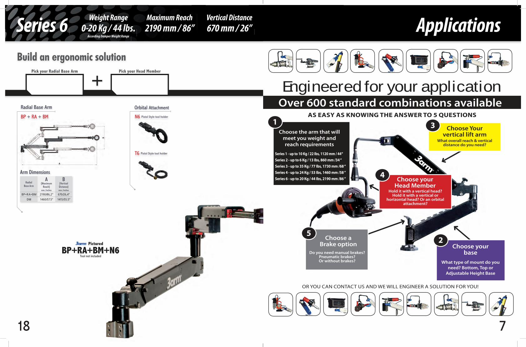
Series 6Weight Range
0-20 Kg / 44 lbs.Maximum Reach
2190 mm / 86”Vertical Distance
670 mm / 26”According Damper Weight Range
BP + RA + BM
Radial Base Arm
Pictured
BP+RA+BM+N6Tool not included
Build an ergonomic solution
+Pick your Head MemberPick your Radial Base Arm
N6 Pistol Style tool holder
T6 Pistol Style tool holder
Orbital Attachment
Arm Dimensions
Radial Base Arm
A(Maximum
Reach)mm./inches
B(Vertical Distance)mm./inches
BP+RA+BM 2190/86,2” 670/26,4”DM 1460/57.5” 1415/55.5”
7
Applications
Engineered for your applicationOver 600 standard combinations available
Choose the arm that will meet you weight and reach requirements
Series 1 - up to 10 Kg / 22 Ibs, 1120 mm / 44‘‘ Series 2 - up to 6 Kg / 13 Ibs, 860 mm /34 ‘‘Series 3 - up to 35 Kg / 77 Ibs, 1730 mm /68 ‘‘Series 4 - up to 24 Kg / 53 Ibs, 1460 mm /58 ‘‘Series 6 - up to 20 Kg / 44 Ibs, 2190 mm /86 ‘‘
AS EASY AS KNOWING THE ANSWER TO 5 QUESTIONS
OR YOU CAN CONTACT US AND WE WILL ENGINEER A SOLUTION FOR YOU!
1
Choose your base
What type of mount do you need? Bottom, Top or
Adjustable Height Base
2
Choose Your vertical lift arm
What overall reach & vertical distance do you need?
3
Choose your Head Member
Hold it with a vertical head? Hold it with a vertical or
horizontal head? Or an orbital attachment?
4
5Choose a
Brake optionDo you need manual brakes?
Pneumatic brakes? Or without brakes?
8
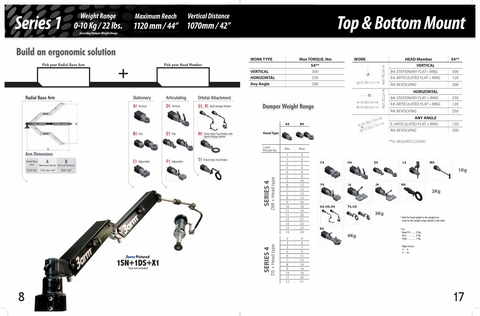
Series 1Weight Range
0-10 Kg / 22 lbs.According Damper Weight Range
Maximum Reach
1120 mm / 44”Vertical Distance
1070mm / 42”
+Build an ergonomic solution
Radial Base Arm
A1 Vertical D1 Vertical
B1 Flat E1 Flat
C1 Adjustable F1 Adjustable
Stationary Articulating
G1, X1 Quik change Gimbal
N1 Pistol-Style Tool Holder with Quick-Change Gimbal
T1 Pistol-Style Tool Holder
Orbital Attachment
Pick your Radial Base Arm Pick your Head Member
Pictured
Tool not included
Arm DimensionsRadial Base
ArmA
(Maximum Reach)B
(Vertical Distance)
1SN+1DS 1120 mm / 44” 1070 / 42”
1SN+1DS+X1
17
WORK HEAD Member S4**
VERTICAL
B4: STATIONARY FLAT+ RING 300
E4: ARTICULATED FLAT + RING 120
R4: REVOLVING 300
HORIZONTAL
B4: STATIONARY FLAT + RING 250
E4: ARTICULATED FLAT + RING 120
R4: REVOLVING 250
ANY ANGLE
E: ARTICULATED FLAT + RING 120
R4: REVOLVING 200
WORK TYPE Max TORQUE. Nm
S4**
VERTICAL 300
HORIZONTAL 250
Any Angle 200
**S4 -REQUIRED LOCKING
Head Type
A4 B4
Load Range Kg Min Max
1 31 32 53 64 85 95 106 127 137 138 159 16
10 1811 1911 2012 2112 2213 2314 24
2 43 63 74 96 117 138 149 16
10 1811 2012 21
SER
IES
4
D
M +
Hea
d t
ype
SE
RIE
S 4
DS
+ H
ead
typ
e
R4
G4, H4, X4 T4, U4
F4 J4 N4
C4
1Kg
2Kg
3Kg
4Kg
D4
I4
E4 L4 M4
* Add the head weight to the weight tool.Look for the weight range wished in the table
* Ex.:Head F4......... 2 KgTool .............. 5 KgTotal: ............ 7 Kg
Right choice:5 - 95 - 10
Damper Weight Range
Top & Bottom Mount

16
Series 4Weight Range
0-24 Kg / 53 lbs.Maximum Reach
1460 mm / 58”Vertical Distance
1375 mm / 54” According Damper Weight Range
DS or DM
Radial Base Arm
A4 Vertical D4 Vertical
B4 Vertical E4 Flat
C4 Adjustable F4 Adjustable
Stationary Articulating
G4, H4, X4 Quick-Change Gimbal
I4 Flat Locatable Surface
J4 Flat Vertical Surface
N4 Pistol-Style Tool
T4, U4 Pistol-Style Tool Holder
Orbital Attachment
TT
R4 Adjustable
L4 Adjustable
L00 None
L22 Pneumatic
L92 Brakes lock by tool trigger
Brakes
Pictured
SN+DS+N4+L00Tool not included
Build an ergonomic solution
Arm Dimensions
Radial Base
A(Maximum
Reach)mm./inches
B(Vertical Distance)mm./inches
Weight RangeKg./Ibs
DS 1220/48” 1020/40” 21/46DM 1460/57.5” 1375/54” 24/53
++Pick your BrakesPick your Head MemberPick your Base Arm
9
Damper Weight Range
Head Type
A1 B1
Load Range Kg Min Min
0 0,9
0,7 2,1
1,4 3,2
2,1 4,3
2,8 5,5
3,6 6,7
4,3 7,7
5 8,9
5,7 10
SER
IES
1 T
OP
&
BO
TTO
M M
ou
nt
1SN
+ 1
DS
+ H
ead
typ
e
* Add the head weight to the weight tool.Search for the weight range wished in the table
* Ex.: Head G1 ...... 2 Kg Tool ............. 3 Kg Total ............ 5 Kg
Right choices: 3,6 - 6,7 4,3 - 7,7
C1
F1
N1
G1/X1
D1
T1
E1
0,5 Kg
1 Kg
1,5 Kg
2 Kg
Top & Bottom Mount

10
Series 2Weight Range
0-6 Kg / 13 lbs.According Damper Weight Range
Maximum Reach
860 mm / 34”Vertical Distance
530 mm / 22”
+Build an ergonomic solution
B BERadial Base Arm
H = 447mm/17.6”
A2 Vertical D2 Vertical
B2 Flat E2 Flat
C2 Adjustable F2 Adjustable
Stationary Articulating
G2, X2 Quik change Gimbal
N2 Pistol Style tool holder
Orbital Attachment
Pick your Radial Base Arm Pick your Head Member
Pictured
B+G2Tool not included
Arm Dimensions
Radial Base A(Maximum Reach)
B(Vertical Distance)
B 860 / 33,9” 530 mm / 21”BE 860 / 33.9” 530 mm / 21”
15
R3
G3, H3, X3 T3, U3
F3 I3 J3 N3, Q3
1Kg
2Kg
3Kg
4Kg
D3 E3 L3 M3
Head Type
A3 B3
Load Range Kg Min Max
1 31 32 53 64 85 95 106 127 137 138 159 16
10 1811 1911 2012 2112 2213 2314 2515 2616 2717 29
17 3018 3118 3219 3320 35
Head Type
A3 B3
Load Range Kg Min Max
0 31 41 52 52 62 73 73 84 94 105 105 116 126 137 147 148 158 168 179 179 18
SER
IES
3 T
OP
& B
OT
TOM
Mo
un
t
AS
or P
S +
BS
+ H
ead
typ
e /
AL
or B
L +
BS
+ H
ead
typ
e
SER
IES
3 T
OP
& B
OT
TOM
Mo
un
t
AS
or P
S +
BM
+ H
ead
typ
e /
AL
or P
L +
BM
+ H
ead
typ
e
* Add the head weight to the weight tool.Look for the weight range wished in the table
* Ex.:Head F3......... 2 KgTool .............. 5 KgTotal: ............ 7 Kg
Right choice:5 - 95 - 10
Damper Weight Range
C3

14
WORK HEAD Member S3*
VERTICAL
B3: STATIONARY FLAT + RING 650
E3: ARTICULATED FLAT + RING 120
R3: REVOLVING 300
HORIZONTAL
B3: STATIONARY FLAT + RING 250
E3: ARTICULATED FLAT + RING 120
R3: REVOLVING 250
ANY ANGLE
E3: ARTICULATED FLAT + RING 120
R3: REVOLVING 200
WORK TYPE Max TORQUE. Nm
S3*
VERTICAL 650
HORIZONTAL 250
ANY ANGLE 200
Series 3
*S3 -RECOMMENDED LOCKING
UNUSABLE AREA WITHOUT LOCKING
11
Damper Weight Range
WORK HEAD Member S2
VERTICAL
B2: STATIONARY FLAT + RING 120
E2: ARTICULATED FLAT + RING 60
HORIZONTAL
B2: STATIONARY FLAT + RING 90
E2: ARTICULATED FLAT + RING 60
ANY ANGLE
E2: ARTICULATED FLAT + RING60
WORK TYPE Max TORQUE. Nm
S2
VERTICAL 120
HORIZONTAL60/90
straight/angular
ANY ANGLE 60
Top & Bottom Mount
Head Type
A2 B2
Load Range Kg Min Min
0 0,6
0,3 1,1
0,6 1,5
0,8 2
1,1 2,4
1,7 3,3
2,3 4,2
2,9 5,1
3,5 6
SER
IES
2 T
OP
&
BO
TTO
M M
ou
nt
B +
Hea
d T
ype
* Add the head weight to the weight tool.Search for the weight range wished in the table
* Ex.: Head G2 ...... 2 Kg Tool ............. 3 Kg Total ............ 5 Kg
Right choices: 3,6 - 6
C2
F2
N2
G2
D2 E2
0,5 Kg
1 Kg
1,5 Kg
2 Kg

12
Series 3Weight Range
0-35 Kg / 77 lbs.Maximum Reach
1730 mm / 68”Vertical Distance
1070 mm / 42”
Build an ergonomic solution
PS or PL
PE
Bottom Radial Base Arm
H = 482mm./19”
BS Small (Length 625 mm / 24”, up to 35 Kg/77 lbs)
BM Medium (Length 925 mm /36”, up to 18 Kg /40 lbs)
Vertical Tilt Arm
Arm Dimensions
Radial BaseA
(Length)mm./inches
Tilting Armmm./inches
B(Length)
mm./inches
C(Vertical Distance)
mm./inches
MaximumReach
mm./inches
PS 450/17.7” BSBM
625/24”925/36”
670/26”1070/42
1075/42”1375/54”
PL 808/31.8” BSBM
610/24.0”910/35.8”
707/27.8”1130/44.5”
1430 / 56”1730/67.6”
PE 500/19.7” BSBM
610/24.0”910/35.8”
707/27.8”1130/44.5”
1125/44”1425/56”
Pictured
PS+BM+D3+L11
+ +Pick your Tilt ArmPick your Base Arm
According Damper Weight Range
13
L00 None
L11 Manual
L50 Manual Lock at Base
L22 Pneumatic
L92 Brakes lock by tool trigger
Brakes
A3 Vertical D3 Vertical G3, H3, X3 Quick-Change Gimbal
B3 Vertical E3 Flat I3 Flat Locatable Surface
C3 Adjustable
F3 Adjustable
R3 Adjustable
L3 Adjustable
J3 Flat Vertical Surface
N3, Q3 Pistol-Style Tool
M3 Constant-Pressure Tool Holder
T3, U3 Pistol-Style Tool Holder
Stationary Articulating Orbital Attachment
+Pick your BrakesPick your Head Member
Top & Bottom Mount